US9631627B2 - Columnar air moving devices, systems and methods - Google Patents
Columnar air moving devices, systems and methodsDownload PDFInfo
- Publication number
- US9631627B2 US9631627B2US15/061,951US201615061951AUS9631627B2US 9631627 B2US9631627 B2US 9631627B2US 201615061951 AUS201615061951 AUS 201615061951AUS 9631627 B2US9631627 B2US 9631627B2
- Authority
- US
- United States
- Prior art keywords
- impeller
- stator
- hub
- air
- outer housing
- Prior art date
- Legal status (The legal status is an assumption and is not a legal conclusion. Google has not performed a legal analysis and makes no representation as to the accuracy of the status listed.)
- Expired - Lifetime, expires
Links
- 238000000034methodMethods0.000titleclaimsabstractdescription10
- 238000011144upstream manufacturingMethods0.000claimsdescription32
- 238000004519manufacturing processMethods0.000claimsdescription3
- 239000006185dispersionSubstances0.000description8
- 238000013517stratificationMethods0.000description7
- 238000004378air conditioningMethods0.000description3
- 230000007423decreaseEffects0.000description3
- 238000010438heat treatmentMethods0.000description3
- XLYOFNOQVPJJNP-UHFFFAOYSA-NwaterSubstancesOXLYOFNOQVPJJNP-UHFFFAOYSA-N0.000description3
- 238000001816coolingMethods0.000description2
- 230000000694effectsEffects0.000description2
- 238000011010flushing procedureMethods0.000description2
- 239000002981blocking agentSubstances0.000description1
- 238000000071blow mouldingMethods0.000description1
- 238000006243chemical reactionMethods0.000description1
- 230000006835compressionEffects0.000description1
- 238000007906compressionMethods0.000description1
- 238000010276constructionMethods0.000description1
- 230000001419dependent effectEffects0.000description1
- 239000000645desinfectantSubstances0.000description1
- 238000009792diffusion processMethods0.000description1
- 230000008020evaporationEffects0.000description1
- 238000001704evaporationMethods0.000description1
- 230000009970fire resistant effectEffects0.000description1
- 239000012530fluidSubstances0.000description1
- 239000003205fragranceSubstances0.000description1
- 230000013011matingEffects0.000description1
- 238000002844meltingMethods0.000description1
- 230000008018meltingEffects0.000description1
- 239000002991molded plasticSubstances0.000description1
- 230000000149penetrating effectEffects0.000description1
- 230000035515penetrationEffects0.000description1
- 230000002093peripheral effectEffects0.000description1
- 239000007921spraySubstances0.000description1
- 238000009423ventilationMethods0.000description1
Images


Classifications
- F—MECHANICAL ENGINEERING; LIGHTING; HEATING; WEAPONS; BLASTING
- F04—POSITIVE - DISPLACEMENT MACHINES FOR LIQUIDS; PUMPS FOR LIQUIDS OR ELASTIC FLUIDS
- F04D—NON-POSITIVE-DISPLACEMENT PUMPS
- F04D25/00—Pumping installations or systems
- F04D25/02—Units comprising pumps and their driving means
- F04D25/08—Units comprising pumps and their driving means the working fluid being air, e.g. for ventilation
- F04D25/088—Ceiling fans
- B—PERFORMING OPERATIONS; TRANSPORTING
- B23—MACHINE TOOLS; METAL-WORKING NOT OTHERWISE PROVIDED FOR
- B23P—METAL-WORKING NOT OTHERWISE PROVIDED FOR; COMBINED OPERATIONS; UNIVERSAL MACHINE TOOLS
- B23P19/00—Machines for simply fitting together or separating metal parts or objects, or metal and non-metal parts, whether or not involving some deformation; Tools or devices therefor so far as not provided for in other classes
- F—MECHANICAL ENGINEERING; LIGHTING; HEATING; WEAPONS; BLASTING
- F04—POSITIVE - DISPLACEMENT MACHINES FOR LIQUIDS; PUMPS FOR LIQUIDS OR ELASTIC FLUIDS
- F04D—NON-POSITIVE-DISPLACEMENT PUMPS
- F04D13/00—Pumping installations or systems
- F04D13/02—Units comprising pumps and their driving means
- F04D13/06—Units comprising pumps and their driving means the pump being electrically driven
- F04D13/0606—Canned motor pumps
- F04D13/0613—Special connection between the rotor compartments
- F—MECHANICAL ENGINEERING; LIGHTING; HEATING; WEAPONS; BLASTING
- F04—POSITIVE - DISPLACEMENT MACHINES FOR LIQUIDS; PUMPS FOR LIQUIDS OR ELASTIC FLUIDS
- F04D—NON-POSITIVE-DISPLACEMENT PUMPS
- F04D19/00—Axial-flow pumps
- F04D19/002—Axial flow fans
- F—MECHANICAL ENGINEERING; LIGHTING; HEATING; WEAPONS; BLASTING
- F04—POSITIVE - DISPLACEMENT MACHINES FOR LIQUIDS; PUMPS FOR LIQUIDS OR ELASTIC FLUIDS
- F04D—NON-POSITIVE-DISPLACEMENT PUMPS
- F04D25/00—Pumping installations or systems
- F04D25/02—Units comprising pumps and their driving means
- F04D25/08—Units comprising pumps and their driving means the working fluid being air, e.g. for ventilation
- F04D25/12—Units comprising pumps and their driving means the working fluid being air, e.g. for ventilation the unit being adapted for mounting in apertures
- F—MECHANICAL ENGINEERING; LIGHTING; HEATING; WEAPONS; BLASTING
- F04—POSITIVE - DISPLACEMENT MACHINES FOR LIQUIDS; PUMPS FOR LIQUIDS OR ELASTIC FLUIDS
- F04D—NON-POSITIVE-DISPLACEMENT PUMPS
- F04D29/00—Details, component parts, or accessories
- F04D29/26—Rotors specially for elastic fluids
- F04D29/32—Rotors specially for elastic fluids for axial flow pumps
- F04D29/325—Rotors specially for elastic fluids for axial flow pumps for axial flow fans
- F04D29/329—Details of the hub
- F—MECHANICAL ENGINEERING; LIGHTING; HEATING; WEAPONS; BLASTING
- F04—POSITIVE - DISPLACEMENT MACHINES FOR LIQUIDS; PUMPS FOR LIQUIDS OR ELASTIC FLUIDS
- F04D—NON-POSITIVE-DISPLACEMENT PUMPS
- F04D29/00—Details, component parts, or accessories
- F04D29/40—Casings; Connections of working fluid
- F04D29/52—Casings; Connections of working fluid for axial pumps
- F04D29/522—Casings; Connections of working fluid for axial pumps especially adapted for elastic fluid pumps
- F—MECHANICAL ENGINEERING; LIGHTING; HEATING; WEAPONS; BLASTING
- F04—POSITIVE - DISPLACEMENT MACHINES FOR LIQUIDS; PUMPS FOR LIQUIDS OR ELASTIC FLUIDS
- F04D—NON-POSITIVE-DISPLACEMENT PUMPS
- F04D29/00—Details, component parts, or accessories
- F04D29/40—Casings; Connections of working fluid
- F04D29/52—Casings; Connections of working fluid for axial pumps
- F04D29/54—Fluid-guiding means, e.g. diffusers
- F04D29/541—Specially adapted for elastic fluid pumps
- F04D29/542—Bladed diffusers
- F—MECHANICAL ENGINEERING; LIGHTING; HEATING; WEAPONS; BLASTING
- F04—POSITIVE - DISPLACEMENT MACHINES FOR LIQUIDS; PUMPS FOR LIQUIDS OR ELASTIC FLUIDS
- F04D—NON-POSITIVE-DISPLACEMENT PUMPS
- F04D29/00—Details, component parts, or accessories
- F04D29/40—Casings; Connections of working fluid
- F04D29/52—Casings; Connections of working fluid for axial pumps
- F04D29/54—Fluid-guiding means, e.g. diffusers
- F04D29/541—Specially adapted for elastic fluid pumps
- F04D29/545—Ducts
- F04D29/547—Ducts having a special shape in order to influence fluid flow
- F—MECHANICAL ENGINEERING; LIGHTING; HEATING; WEAPONS; BLASTING
- F04—POSITIVE - DISPLACEMENT MACHINES FOR LIQUIDS; PUMPS FOR LIQUIDS OR ELASTIC FLUIDS
- F04D—NON-POSITIVE-DISPLACEMENT PUMPS
- F04D29/00—Details, component parts, or accessories
- F04D29/60—Mounting; Assembling; Disassembling
- F04D29/601—Mounting; Assembling; Disassembling specially adapted for elastic fluid pumps
- F—MECHANICAL ENGINEERING; LIGHTING; HEATING; WEAPONS; BLASTING
- F21—LIGHTING
- F21V—FUNCTIONAL FEATURES OR DETAILS OF LIGHTING DEVICES OR SYSTEMS THEREOF; STRUCTURAL COMBINATIONS OF LIGHTING DEVICES WITH OTHER ARTICLES, NOT OTHERWISE PROVIDED FOR
- F21V33/00—Structural combinations of lighting devices with other articles, not otherwise provided for
- F21V33/0088—Ventilating systems
- F21V33/0096—Fans, e.g. ceiling fans
- F—MECHANICAL ENGINEERING; LIGHTING; HEATING; WEAPONS; BLASTING
- F24—HEATING; RANGES; VENTILATING
- F24F—AIR-CONDITIONING; AIR-HUMIDIFICATION; VENTILATION; USE OF AIR CURRENTS FOR SCREENING
- F24F7/00—Ventilation
- F24F7/007—Ventilation with forced flow
- F—MECHANICAL ENGINEERING; LIGHTING; HEATING; WEAPONS; BLASTING
- F04—POSITIVE - DISPLACEMENT MACHINES FOR LIQUIDS; PUMPS FOR LIQUIDS OR ELASTIC FLUIDS
- F04D—NON-POSITIVE-DISPLACEMENT PUMPS
- F04D29/00—Details, component parts, or accessories
- F04D29/40—Casings; Connections of working fluid
- F04D29/42—Casings; Connections of working fluid for radial or helico-centrifugal pumps
- F04D29/4206—Casings; Connections of working fluid for radial or helico-centrifugal pumps especially adapted for elastic fluid pumps
- F04D29/4226—Fan casings
- F—MECHANICAL ENGINEERING; LIGHTING; HEATING; WEAPONS; BLASTING
- F24—HEATING; RANGES; VENTILATING
- F24F—AIR-CONDITIONING; AIR-HUMIDIFICATION; VENTILATION; USE OF AIR CURRENTS FOR SCREENING
- F24F2221/00—Details or features not otherwise provided for
- F24F2221/02—Details or features not otherwise provided for combined with lighting fixtures
- F—MECHANICAL ENGINEERING; LIGHTING; HEATING; WEAPONS; BLASTING
- F24—HEATING; RANGES; VENTILATING
- F24F—AIR-CONDITIONING; AIR-HUMIDIFICATION; VENTILATION; USE OF AIR CURRENTS FOR SCREENING
- F24F2221/00—Details or features not otherwise provided for
- F24F2221/14—Details or features not otherwise provided for mounted on the ceiling
Definitions
- the present inventionrelates to heating, ventilating and air conditioning air spaces, and more particularly to systems, devices and methods for moving air in a columnar pattern with minimal lateral dispersion that are particularly suitable for penetrating air spaces and air temperature de-stratification.
- Ceiling fansare relatively large rotary fans, with a plurality of blades, mounted near the ceiling.
- the blades of a ceiling fanhave a flat or airfoil shape.
- the bladeshave a lift component that pushes air upwards or downwards, depending on the direction of rotation, and a drag component that pushes the air tangentially.
- the drag componentcauses tangential or centrifugal flow so that the air being pushed diverges or spreads out.
- Conventional ceiling fansare generally ineffective as an air de-stratification device in relatively high ceiling rooms because the air pushed by conventional ceiling fans is not maintained in a columnar pattern from the ceiling to the floor, and often disperses or diffuses well above the floor.
- Another proposed solution to air temperature stratificationis a fan connected to a vertical tube that extends substantially from the ceiling to the floor.
- the fanmay be mounted near the ceiling, near the floor or in between. This type of device may push cooler air up from the floor to the ceiling or warmer air down from the ceiling to the floor.
- Such deviceswhen located away from the walls in an open space in a building, interfere with floorspace use and are not aesthetically pleasing. When confined to locations only along the walls of an open space, such devices may not effectively circulate air near the center of the open space. Examples of fans connected to vertical tubes are disclosed in U.S. Pat. No. 3,827,342 to Hughes, and U.S. Pat. No. 3,973,479 to Whiteley.
- U.S. Pat. Nos. 4,473,000 and 4,662,912 to Perkinsdisclose a device having a housing, with a rotating impeller having blades in the top of the housing and a plurality of interspersed small and large, vertically extending, radial stationary vanes spaced below the impeller in the housing.
- the device disclosed by Perkinsis intended to direct the air in a more clearly defined pattern and reduce dispersion.
- Perkinsdoes not disclose the importance of a specific, relatively small gap between the impeller blades and the stationary vanes, and the device illustrated creates a vortex and turbulence due to a large gap and centrifugal air flow bouncing off the inner walls of the housing between the blades and vanes.
- Perkinsalso discloses a tapering vane section. The tapering vane section increases velocity of the exiting air stream.
- a device with a rotary fan that minimizes the rotary component of the air flow while maximizing the axial air flow quantity and velocitycan provide a column of air that flows from a high ceiling to a floor in a columnar pattern with minimal lateral dispersion that does not require a physical transporting tube.
- Such a deviceshould reduce the energy loss by minimizing the rotary component of the air flow, and therefore minimizes turbulence.
- Such a deviceshould minimize back pressure, since a pressure drop at the outlet of the device will cause expansion, velocity loss and lateral dispersion.
- the deviceshould have minimum noise and low electric power requirements.
- An air moving devicewhich has a housing with an air inlet and an air outlet spaced from the inlet.
- a rotary impeller with a plurality of bladesis mounted in the housing at the air inlet end and produces air flow with an axial component and a rotary component.
- a plurality of spaced, longitudinally extending, radial air guide vanes in the housing downstream of the impellerare in close proximity to the impeller blades to minimize the rotary component and change the air flow to a laminar and axial flow in the housing that exits the outlet end in a columnar pattern with minimal lateral dispersion.
- a method of moving airincludes producing an air flow through a housing, and directing the air flow through the housing in a laminar and axial flow and exits an outlet so as to produce a columnar pattern with minimal lateral dispersion.
- the methodalso includes directing warm air from near the ceiling toward the floor, allowing the heat from the warm air to be stored in the floor, articles on the floor and the earth under the floor.
- the methodincludes directing air in a generally horizontal direction to allow penetration of an air space in a container, trailer truck or a room to promote flushing of that air space and circulation thereof.
- the device and methodare particularly suitable for high efficiency, low power usage, air temperature de-stratification, and to improve air quality and circulation.
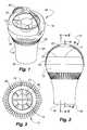
- FIG. 1is a top perspective view of an air moving device embodying features of the present invention.
- FIG. 2is a side elevation view of the device of FIG. 1 .
- FIG. 3is a bottom view of the device of FIG. 1 .
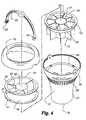
- FIG. 4is an exploded perspective view of the device 5 of FIG. 1 .
- FIG. 5is a sectional view taken along line 5 - 5 of FIG. 2 .
- FIG. 6is a sectional view taken along line 6 - 6 of FIG. 2 .
- FIG. 7is a sectional view taken along line 5 - 5 of FIG. 2 , with straight upstream portions of the vanes.
- FIG. 8is a side elevation view of the device of FIG. 1 showing angular direction of the device.
- FIG. 9is an enlarged, partial exploded view of the hangar attachment of the device of FIG. 1 .
- FIG. 10is a side view of a room with the device of FIG. 1 showing an air flow pattern with dashed lines and arrows.
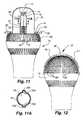
- FIG. 11is a side elevation view, partially cut away, showing the device of FIG. 1 modified for attachment to a light can.
- FIG. 11Ais a sectional view taken along line 11 A- 11 A of FIG. 11 .
- FIG. 12is a side elevation view of the device of FIG. 1 with an intake grill.
- FIG. 13is a sectional view taken along line 6 - 6 of FIG. 2 of the device of FIG. 1 with a misting nozzle.
- FIG. 14is a side elevation view of the device of FIG. 1 in combination with a tube and second air moving device.
- FIG. 15is a bottom perspective view, partially cut away, showing the device of FIG. 1 mounted in a drop ceiling.
- FIG. 15Ais a top perspective view of FIG. 15 .
- FIG. 15Bis a top perspective view of the fastening member shown in FIG. 15A
- FIG. 15Cis a sectional view taken along FIG. 15C-15C of FIG. 15A .
- FIG. 15Dis a sectional view along line 15 D- 15 D of FIG. 15A .
- FIG. 16is an enlarged view of a portion of FIG. 15 .
- FIG. 17is a side elevation view, partially cut away, showing the device of FIG. 1 modified for attachment to a light socket and having a light bulb at the lower end.
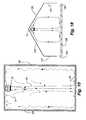
- FIG. 18is a schematic view of an open sided tent with an air moving device in the top.
- FIG. 19is a schematic view of a shipping container with an air moving device at one lower end.
- FIGS. 20-24are schematic representations of a plurality of air moving devices used to create a cascading airflow.
- an air moving device 12having an elongated outer housing 13 , an electric rotary fan 14 in the housing for producing air flow in the housing and a plurality of longitudinally extending, outer radial vanes 15 and an inner housing hub 16 opposite the vanes in the housing downstream of the fan for directing air flow in the housing.
- the housing 13has a circular cross section, and an open first end 17 and an open second end 18 spaced from the first end 17 .
- a detachable, axially outwardly convex cowling 19forms the first end 17 and provides an air inlet 21 with a diameter slightly smaller than the outer diameter of the cowling 19 .
- the housing 13has a first section 25 extending from the cowling 19 to an interior shelf 26 .
- a generally C shaped hanger 23mounts at opposite ends 24 to opposite sides of the housing 13 at the upper end of the first section 25 , for mounting the air moving device 12 to a support.
- the first section 25when viewed from the side, has a curved, slightly radially outwardly convex shape that conforms to the curvature of the cowling 19 .
- the shelf 26extends radially inwardly to join with the upstream end of a second section 27 .
- the second section 27tapers inwardly and extends axially from the shelf 26 to the second end 18 along a smooth curve that goes from radially outwardly convex near the shelf 26 to radially outwardly concave near the second end 18 .
- the second end 18forms an air outlet 28 that has a smaller diameter than the air inlet 21 .
- a plurality of circumferentially spaced external fins 29extend from the shelf 26 to the second section 27 to provide the appearance of a smooth curve from the air inlet 21 to the air outlet 28 when the housing 13 is viewed from the side.
- the fan 14includes an impeller 31 having a cylindrical, inner impeller hub 32 , with an electric motor 34 therein, and a plurality of rigidly mounted, circumferentially spaced blades 33 extending radially from the impeller hub 32 .
- the impeller 31has three equally spaced blades 33 and rotates about an axis in a counter-clockwise direction when viewed from above.
- Each blade 33in side view, extends from an upstream edge 35 , downwardly and leftwardly to a downstream edge 36 with each blade 33 being slightly concave, in an airfoil or wing shape, downwardly to propel air rightwardly as shown by the arrow.
- Each blade 33then inclines at a selected angle to the axis of rotation of the impeller.
- Each blade 33 shownextends axially and radially toward the outlet or second end 18 to direct air axially with a rotary component. If the motor 34 runs in the opposite direction, the incline of the blades 33 would be reversed.
- the fan 14includes a stationary cylindrical mounting ring 38 that extends around the blades 33 , with the impeller hub 32 being rotably mounted relative to the mounting ring 38 .
- the mounting ring 38has spaced, protruding upstream and downstream rims 40 and 41 .
- the fan 14mounts in the housing 13 between the cowling 19 and the shelf 26 .
- Each of the vanes 15is identical and includes upstream portion 43 and a downstream portion 44 .
- the upstream portion 43is carried in a stator 46 .
- the stator 46has a cylindrical stator hub 47 with a diameter substantially equal to the diameter of the impeller hub 32 .
- the upstream portions 43 of the vanes 15are mounted in a circumferentially spaced arrangement around the stator hub 47 , and extend longitudinally along and radially from the stator hub 47 .
- Each upstream portion 43has an upstream end 48 and a downstream end 49 .
- a support body 50includes a cylindrical stator ring 52 that extends around the upstream portions 43 and connects to the outer ends of the upstream portions 43 of the vanes 15 near the upstream ends 48 .
- the support body 50also includes a protruding stator rim 53 that is substantially planar with the upstream ends 48 of the upstream portions 43 of the vanes 15 , and that connects to the stator ring 52 and extends radially outwardly therefrom.
- the housing 13has, an inner surface and the inner housing hub 16 has an outer surface concentric with a spaced from the housing inner surface to define an air flow passage through the housing.
- the inner housing hub 16includes the fan hub 32 , stator hub portion 47 and downstream hub portion 57 , each having an outer surface and arranged end to end along the center of the housing and opposite and spaced from the housing inner surface to define the air flow passage.
- these outer surfaces shownare cylindrical and substantially the same diameter for a substantial portion of the passage and as the housing 13 converges the downstream hub portion 57 converges to generally follow the curvature of the inside surface of the housing.
- the stator 46nests in and is separable from the housing 13 with the stator rim 53 between the shelf 26 of the housing 13 and the downstream rim 41 of the mounting ring 38 of the fan 14 , and with a gap 55 having a selected size between the downstream edge 36 of the blades 33 of the impeller 31 and the upstream ends 49 of the upstream portions 43 of the vanes 15 . If the gap 55 is too large, turbulence will be generated in the air flow between the impeller 31 and the vanes 15 , reducing the velocity of the air flow. If the gap 55 is too small, fluid shear stress will generate noise.
- the size of the gap 55is generally selected as no greater than a maximum selected dimension to avoid turbulence and no less than a selected minimum dimension to avoid noise, and more particularly selected as small as possible without generating noise.
- the selected size of the gap 55is generally proportional to the diameter of the impeller 31 and may further be affected by the speed of the impeller 31 .
- the maximum size of the gap 55For an impeller 31 with a diameter of 8.5′′, at 1400 rpm, the maximum size of the gap 55 should be 1.25′′, and the minimum gap should be 0.2′′ but could be 0.020 for lower rpm's as the size of the gap is rpm dependent.
- the maximum size of the gap 55should be less than one half the diameter of the impeller 31 .
- each curved vane portionis inclined at an angle opposite the incline of the blade 33 that extends axially and radially inward toward the outlet or second end 28 to assist in converting the rotary component of the air flow into laminar and axial flow in the housing.
- Straight upstream portions 43 A of the vanes 15may also be used, as shown in FIG. 7 , and other numbers of vanes 15 may be used. Further, if the motor 34 runs in the opposite direction, the incline of the curvature near the upstream ends 48 would be reversed.
- the downstream portions 44 of the vanes 15attach at an inner end to a downstream inner housing hub portion 57 , are circumferentially spaced and extend radially outwardly from the housing hub portion 57 to the housing 13 .
- the housing hub portion 57 and the downstream portions 44 of the vanes 15extend axially from the stator 46 to or near the air outlet 28 .
- the housing hub portion 57has a circular cross section, has a diameter substantially equal to the diameter of the stator housing hub portion 47 at the upstream end adjacent to the stator housing hub portion 47 , and tapers downstream to a point 58 near the air outlet 28 .
- This hub portionmay be characterized as torpedo shaped.
- Other numbers of downstream portions 44 of the vanes 15can be used.
- the number of the blades 33may be 2, 3, 4, 5, 6, 7 or 8.
- the number of the vanes 15may be 2, 3, 4, 5, 6, 7 or 8.
- the number of vanes 15should be different from the number of blades 33 . If the number of vanes 15 and blades 33 are the same, added noise is generated due to harmonics.
- the air moving device 12discharges air at a high velocity in a generally axial flow having a columnar pattern with minimal lateral dispersion after exiting the air outlet 28 .
- the cowling 19extends along a curve toward the inside to reduce turbulence and noise for air flow entering the air inlet 21 .
- the impeller hub 32 , the stator hub 47 and the housing hub 57form the inner housing hub 16 .
- the taper of the housing hub 57generally follows the taper of the housing 13 So that the cross sectional area for air flow decreases about 10% to 35% through the air moving device 12 to avoid back pressure and at the same time increase air flow velocity. In the embodiment shown the air flow decreases about 22%.
- the vanes 15convert the rotary component of the air flow from the impeller 31 into laminar and axial air flow in the housing.
- the leftward curve of the upstream ends 48 of the upstream portions 43 of the vanes 15reduces the energy loss in the conversion of the rotary component of the air flow from the impeller 31 into laminar and axial air flow in the housing.
- the small gap 55 between the impeller 31 and vanes 15prevents the generation of turbulence in the air flow in the gap 55 .
- the taper of the housing 13 in combination with the taper of the housing hub 57 to the point 58allows the air flow to exit the air outlet 28 in a continuous, uninterrupted columnar pattern with minimal dispersion, with no center hole or gap at a linear speed greater than would be imparted by a fan alone.
- the inside surface of the housing 13is a substantially smooth uninterrupted surface to minimize turbulence and energy loss.
- the hanger 23is mounted to rotate and lock relative to the housing 13 , so that when the hanger 23 is attached to an overhead support such as ceiling, the air flow from the air moving device 12 may be directed vertically or aimed at any selected angle from the vertical as shown in FIG. 8 .
- the first section 25 of the housing 13includes mounting tabs 91 on opposite sides on the upper edge of the first section 25 .
- Each mounting tab 91includes a round, outwardly directed mounting face 92 , and a housing aperture 93 that extends inwardly through the center of the mounting tab 91 .
- a pair of outwardly projecting housing ridges 94extend radially on the mounting face 92 on opposite sides of the housing aperture 93 .
- Each end 24 of the hanger 23has a round, inwardly facing hanger end face 96 , similar in size to the mounting face 92 on the housing 13 .
- a hanger end aperture 97extends through the center of the hanger end face 96 .
- a plurality of spaced, radially extending grooves 98sized to receive the housing ridges 94 , are provided on each hanger end face 96 .
- Bolt 100extends through the hanger end aperture 97 and threads into an internally threaded cylindrical insert 101 , rigidly affixed in housing aperture 93 .
- the angle of the housing 13is chosen by selecting a pair of opposed grooves 97 on each hanger end 24 to receive the housing ridges 94 .
- the pivotal arrangementenables the housing to move to a selected angle and is lockable at the selected angle to direct air flow at the selected angle.
- FIG. 10shows an air moving device 12 mounted to the 13 ceiling 62 of a room 63 shown as being closed sided with opposed side walls.
- Warm air near the ceiling 62is pulled into the air moving device 12 .
- the warm airexits the air moving device 12 in a column 64 that extends to the floor 65 .
- the warm air from the ceilingpushes the colder air at the floor 65 outward towards the opposed side walls 66 and upward towards the ceiling 62 .
- the warm air from the ceilingwill also transfer heat into the floor 65 , so that heat is stored in the floor 65 .
- the stored heatis released when the ceiling is cooler than the floor.
- the heatmay also be stored in articles on the floor and earth under the floor.
- the air moving device 12destratifies the air in a room 63 without requiring the imperforate physical tube of many prior known devices.
- the air moving device 12destratifies the air in a room 63 with the warmer air from the ceiling 62 minimally dispersing before reaching the floor 65 , unlike many other prior known devices.
- the air moving device 12will also remove dead air anywhere in the room. It is understood that the air moving device 12 may also be mounted horizontally in a container, trailer truck or room as is describe hereafter.
- an air moving device 12is fitted with an inlet grill 68 and an electric connector 69 for attachment to a light can 70 with a light bulb socket 71 at the upper end.
- the inlet grill 68includes a plurality of circumferentially spaced grill fins 72 that attach to the first end 17 of the housing 13 .
- the grill fins 72are separated by air intake slots 73 , and extend axially outwardly from the first end 17 and curve radially inwardly and are integral with a flat circular mounting plate 74 that is substantially parallel with the first end 17 .
- the electrical connector 69has a tube 76 that is integral at one end with the center of the mounting plate 74 and extends axially therefrom, and a light bulb type, right hand thread externally threaded male end 77 attached to the other end of the shaft 78 .
- Grill 68 , plate 74 and tube 76are shown as made of a one piece construction.
- Plate 74has holes that received screws 83 or like fasteners to fasten plate 74 to ceiling 62 .
- the shaft 78telescopes in the tube 76 .
- the tube 76has a pair of opposed keyways 76 A that receive keys 78 A on the shaft 78 which allow axial sliding movement of the shaft 78 in the tube 76 .
- a compression spring 75fits in the tube and bears against the bottom of shaft 78 and top of plate 74 .
- the shaft 78has a selected length relative to the length of the can 70 such that when the air moving device 12 is mounted in a can 70 in a ceiling 62 , the threaded male end 77 engages the socket 71 before the mounting plate 74 contacts the ceiling 62 and when the threaded male end 77 is screwed into the socket 71 , the mounting plate 74 bears against the ceiling 62 .
- the spring 75is compressed between plate 74 and shaft 78 . Screws 83 fasten the plate to the ceiling 62 . Since the light can 70 may be open to air above the ceiling 62 , the mounting plate 74 is preferably sized to cover the open lower end of the can 70 , so that only air from below the ceiling 62 is drawn into the air moving device 12 .
- the air moving device 12 fitted with the inlet grill 68 and the electrical connector 69can also be used with a ceiling light socket.
- the air moving device 12may include an intake grill 79 for preventing objects from entering the impeller 31 , as shown in FIG. 12 .
- the intake grill 79 shownhas a substantially hemispherical shape, and includes a plurality of circumferentially spaced grill fins 80 separated by intake slots 81 .
- the grill fins 80extend axially outwardly and curve radially inwardly from the first end 17 of the housing 13 to a central point 82 spaced from the first end 17 .
- Other shapes of intake grillsare suitable for the present invention.
- FIG. 13shows an air moving device 12 with a misting nozzle 84 .
- the nozzle 84extends through the point 58 of the housing hub 57 to spray water into the column of air exiting the air outlet 28 to cool the air through evaporation.
- the media exiting the nozzle 84 and being supplied through tube 85can have other purposes such as a disinfectant or a fragrance or a blocking agent for distinctive needs.
- the nozzle 84connects to a water line 85 , in the housing hub 59 that connects to a water source (not shown).
- FIG. 14shows an air moving system 86 for use in buildings with very high ceilings, including an air moving device 12 , an upwardly extending, tube 87 (shown cut away) connected at a lower end to the air inlet 21 of the air moving device 12 , and a truncated upper air moving device 88 having an air outlet 89 connected to the upper end of the tube 87 .
- the housing of device 88is called truncated because it may be shortened or cut off below the fins 29 .
- a conventional air moving device 12may be used for device 88 .
- the tube 87may be flexible and is preferably fire resistant.
- the air moving system 86is mounted to a ceiling or like support with the air outlet 28 of the air moving device 12 spaced above the floor, preferably about 10 to 50 feet.
- the tubemay be for example from 30 to 100 feet long.
- the upper air moving device 88 at the top of the system 86has a higher air moving flow capacity than the air moving device 12 at the bottom of the cascading system 86 .
- the upper air moving device 88may have a capacity of 800 cfm and the air moving device 12 may have a capacity of 550 cfm.
- FIGS. 15, 15A, 15B, 15C, 15D and 16show the air moving device 12 mounted in an opening 103 in a ceiling 104 .
- a generally cylindrical can 105mounts on and extends above the ceiling 104 , and has an open can bottom 106 , and a closed can top 107 .
- the can top 107includes a semi-circular, downward opening, circumferentially extending channel 108 .
- a semi-circular fin 111extends radially across the channel 108 to prevent swirling of the air before entering the air inlet 21 . Additional fins may be used.
- a grill and support assembly 125mounts to the ceiling and extends and connects to the exterior of the housing of device 12 .
- a grillincluding spaced openings 110 between fins 109 to allow air to flow up from the room along the housing and past the cowling 19 into the inlet 21 .
- the grill and support assembly 125includes an outer ring 120 fastened to the underside of the ceiling including the convexly curved grill fins 109 with air openings 110 between connected outer ring 120 and an inner ring 121 .
- Ring 121has a spherical concave inner bearing surface 122 .
- a ring 123has a spherical convexly curved exterior bearing surface 124 is mounted on and affixed to the housing with bearing surfaces 122 and 124 mating in a frictional fit to support the housing to be at a vertical position or tilted at an angle to the vertical axis and be held by friction at the vertical axis or a selected angle relative to the vertical axis to direct air flow as required.
- the can 105has an outwardly extending bottom flange 140 that fits against the underside of the ceiling 104 .
- the can 105preferably has four circumferentially spaced bottom openings 141 at 90 degree intervals that are rectangular in shape and extend up the can wall a short distance from the bottom flange 140 .
- a clamping member 142preferably made as a molded plastic body has a main body portion 143 above the ceiling 104 outside the can wall and an end flange portion 144 that fits inside the can opening 142 .
- the main body portion 143has a U-shaped outer wall portion 145 and an inner hub portion 146 having an aperture 147 .
- the clamping member 142inserts into the opening 141 via the open end of the can.
- a bolt fastener 151extends through a hole in the flange, through a hole in the ceiling and threads into the aperture 147 in the main body portion to clamp the can 105 to the ceiling 104 .
- the grill and support assembly 125is mounted to the ceiling 104 and can 105 by a bolt fastener 149 extending through an aperture in ring 120 , through the ceiling 104 and into a nut 150 in flange 140 in the can.
- a bolt fastener 149extending through an aperture in ring 120 , through the ceiling 104 and into a nut 150 in flange 140 in the can.
- the ceiling 104typically would be a plasterboard ceiling in which a suitable hole is cut.
- a variation of FIG. 15would be to extend or form the peripheral of outer ring 120 into a flat panel having a dimension of 2 ft. by 2 ft. that would fit in and be held by a grid that holds a conventional ceiling panel.
- an air moving deviceis fitted with an inlet grill 113 , a light bulb style threaded male end 114 for threading into a light bulb socket, and a light bulb socket 115 .
- the inlet grill 113includes a plurality of circumferentially spaced grill fins 116 that attach to the first end of the housing 13 .
- the grill fins 116are separated by air intake slots 117 , and extend axially outwardly from the first end 17 and curve radially inwardly to a flat circular mounting plate 118 that is substantially parallel with and spaced axially from the first end 17 .
- Threaded male end 114is mounted on and extends upwardly from the mounting plate 118 .
- the socket 115is mounted inside the housing 13 in a downwardly opening fashion so that light from a bulb 119 threaded into the socket 115 is directed downwards.
- FIG. 18there is shown a tent having an inclined top 132 extending down from an apex and connected at the lower end to a vertical side wall 131 and terminating above a floor 133 to provide a side opening 134 so that the tent is an open sided room.
- the air moving device 12is mounted below the top apex and directs the air in the room downwardly in a columnar pattern to the floor and along the floor and then back with some air passing in and out the side openings 134 along the floor 133 . For wide tents, the air will pass up before it reaches the side walls.
- the air moving device and system herein describedhas relatively low electrical power requirement.
- a typical fan motoris 35 watts at 1600 rpm for an impeller of 8.5′′ that will effectively move the air from the ceiling to the floor in a room having a ceiling height of 30 ft.
- Another exampleis 75 watts with an impeller diameter 8.5′′ at 2300 rpm in a room having a ceiling height of 70 ft.
- FIG. 19there is shown a shipping container 161 having an air moving device 12 disposed horizontally in the lower left end.
- the device 12directs the air horizontally along the bottom wall or floor, up the opposite side wall and across the top wall to exit an outlet duct 162 above and spaced from the device 12 of the air moving device.
- the device 12will penetrate the air and promote flushing and circulation of the air space.
- the device 12may be mounted to direct the air generally horizontally or up or down at an angle to the true horizontal. This arrangement may be provided in other air spaces such as a trailer truck, room or the like.
- stator 46 and housing 13could be made as a single unit. It is also understood that the housing 13 may be made in two sections as for example a tubular section of a selected length may be added to the end of a truncated devices as shown in FIG. 14 .
- a plurality of the air moving devices 12 described abovecan be used to create a cascading flow of air from one location to a second location.
- a plurality of air moving devices 12can be positioned at or near the ceiling of a room or roof of a building.
- the air moving devicescan be positioned within 4 feet of the floor, within 8 feet of a floor, within 12 feet of a floor or greater than 12 feet from the floor.
- the air moving devices 12can be distanced apart from one another. The distances between the air moving devices 12 can vary. In some embodiments the distances can be equal between each air moving device 12 .
- the distance between a first and second air moving device 12can be different than the distance between the second and a third air moving device 12 . In some embodiments the distance between two air moving devices 12 can be approximately 5 feet, 10 feet, 15 feet, 20 feet, 25 feet, 30 feet, 35 feet, or any other desired distance.
- the air moving devices 12can be angled and/or positioned such that the air flow exiting a first air moving device 12 is directed generally towards a second air moving device 12 and/or the air flow exiting the second air moving device 12 .
- the air flow exiting the first air moving device 12 and the air flow exiting the second air moving device 12are directed generally in the same direction, such that when the air flow exiting the first air moving device 12 reaches the air flow exiting the second air moving device 12 , the two air flows generally merge together.
- the air moving devices 12can be arranged such that as the air flow of a first air moving device 12 is at least 80% of its initial velocity, at least 60% of its initial velocity, at least 40% of its initial velocity, at least 20% of its initial velocity, or at least 10% of its initial velocity before the airflow of the first air moving device 12 encounters and/or is accelerated into the higher velocity air flow created by a second air moving device 12 .
- the second air moving deviceaccelerates the air to at least 120%, at least 140%, 160%, 200%, 300%, 400%, 500% of the velocity of the air flow when the air flow from the first air moving device encounters and/or is accelerated into the higher velocity air flow created by a second air moving device 12 .
- the second air moving device 12acts to cascade the air from the first air moving device 12 , and to continue to push it along with the air flow from the second air moving device 12 .
- at least a portion of the air flow from the first air moving device 12also enters the second air moving device 12 , and is directed back out the second air moving device 12 at a higher velocity.
- both the second air moving device 12can be used to propel the air flow from the first air moving device 12 .
- a cascading effectcan be achieved, in which the air moving devices 12 work together to move air.
- This cascading effectcan advantageously be used to create a continuous movement of air throughout long stretches of space. This continuous movement of air can help to ventilate, clean, cool, and/or prevent stale air pockets from building up over time.
- While the air moving devices 12can be used within buildings, they can also be used outdoors. For example, people are often required to stand in long lines at amusement parks or other locations. The long lines can extend partially within a building, and/or outside a building. Heat can build up over time, making people uncomfortable as they wait, as can pockets of stale air. Thus, a plurality of air moving devices 12 can be arranged and/or mounted outdoors as well, to help cool and/or remove pockets of stale air.
- a plurality of air moving devices 12can be arranged, for example, to move cool air from a first location into a second location.
- cool aircan be moved from a street level location to a subway or train station terminal.
- the air moving devices 12can be spaced apart and angled such that a continuous airflow is created within the terminal.
- the continuous airflowcan direct air down from street level towards the platform level of the terminal (see FIGS. 21, 23 ), then generally parallel to a train or train track along the platform (see FIG. 23 ), and finally back up from the platform level to the street level again (see FIGS. 22, 23 ).
- the air flow devices 12can work in concert to create the continuous airflow, helping to cool the subway or train station terminal, and/or to eliminate pockets of stale air that have built up within the terminal. This cascading movement of air can especially be useful at night, when the air at the street level is cool, and fresh. During night, when there are fewer people, and the trains are not running, the air moving devices 12 can be operated at high speeds to help quickly cool the terminal area, and then be run at lower speeds during the daytime when the people in the terminal area.
- a plurality of air moving devices 12can also be arranged such that some of the air moving devices 12 are angled to direct air in a cascading manner as described above, whereas other air moving devices 12 are angled to direct air downwardly.
- This arrangement of air moving devices 12can advantageously be used in commercial areas, such as grocery stores. For example, as illustrated in FIG. 24 , air can be directed in through a roof unit 164 . Once the air is inside the building (e.g. grocery store), the air moving devices 12 can pick up the air and move it in a cascading manner within the store to cool and/or eliminate pockets of stale air.
- Some of the air moving devices 12can be angled so as to direct the air in a downward manner, cooling areas such as aisles or other portions of the store that may need to be cooled. This combination of cascading and downward cooling can help to keep the store as fresh, and comfortable, as possible.
- moving air laterally and in a cascading mannercan advantageously be used where it is not possible to use ductwork to achieve the same purpose, or where ductwork would be too expensive or too large.
- ductworkFor example, often the clearance within a commercial or manufacturing building's roof is not suitable for use of ductwork.
- the ductwork for such buildingscan be costly, and can incorporate multiple pipes or other structures which accumulate losses.
- Ductworkis also often not available for areas in which people are waiting in line (e.g. waiting to get into rides as described above).
- manufacturing processessuch as blow molding are used. These processes generate large amounts of heat (e.g. in the form of a heat plume) that need to be moved to other areas of the building to prevent electronics in the area (e.g.
- ductworkis also often not appropriate because the runs may be 500 feet or more.
- the ductworkwould need to be very large, and the motors would need to be very large as well in order to move propel the air, resulting in high cost.
- the ceilings of these buildingsare often filled with conveyers and other objects that would make such large ductwork unfeasible.
- using a plurality of air moving devices 12which cascade the air as described above, would be advantageous alternatives for ductwork in these and the other structures and setting described above.
Landscapes
- Engineering & Computer Science (AREA)
- Mechanical Engineering (AREA)
- General Engineering & Computer Science (AREA)
- Physics & Mathematics (AREA)
- Fluid Mechanics (AREA)
- Chemical & Material Sciences (AREA)
- Combustion & Propulsion (AREA)
- Structures Of Non-Positive Displacement Pumps (AREA)
Abstract
Description
This application is a continuation of U.S. application Ser. No. 13/365,223, filed Feb. 2, 2012, incorporated in its entirety by reference herein, which is a continuation-in-part of U.S. application Ser. No. 12/130,909, filed May 30, 2008, incorporated in its entirety by reference herein, which is a continuation of U.S. application Ser. No. 11/027,039, filed Dec. 30, 2004 now U.S. Pat. No. 7,381,129, issued Jun. 3, 2008, incorporated in its entirety by reference herein, which claims the benefit under 35 U.S.C. §119(e) to U.S. Provisional Patent Application No. 60/553,720 filed Mar. 15, 2004, which is incorporated in its entirety by reference herein. U.S. application Ser. No. 13/365,223 also claims the benefit under 35 U.S.C. §119(e) to U.S. Provisional Patent Application No. 61/521,270 filed Aug. 8, 2011, which is incorporated in its entirety by reference herein.
Field of the Invention
The present invention relates to heating, ventilating and air conditioning air spaces, and more particularly to systems, devices and methods for moving air in a columnar pattern with minimal lateral dispersion that are particularly suitable for penetrating air spaces and air temperature de-stratification.
Description of the Related Art
The rise of warmer air and the sinking of colder air creates significant variation in air temperatures between the ceiling and floor of buildings with conventional heating, ventilation and air conditioning systems. Such air temperature stratification is particularly problematic in large spaces with high ceilings such as warehouses, gymnasiums, offices, auditoriums, hangers, commercial buildings, and even residences with cathedral ceilings, and can significantly decrease heating and air conditioning costs. Further, both low and high ceiling rooms can have stagnant or dead air. For standard ceiling heights with duct outlets in the ceiling there is a sharp rise in ceiling temperatures when the heat comes on.
One proposed solution to air temperature stratification is a ceiling fan. Ceiling fans are relatively large rotary fans, with a plurality of blades, mounted near the ceiling. The blades of a ceiling fan have a flat or airfoil shape. The blades have a lift component that pushes air upwards or downwards, depending on the direction of rotation, and a drag component that pushes the air tangentially. The drag component causes tangential or centrifugal flow so that the air being pushed diverges or spreads out. Conventional ceiling fans are generally ineffective as an air de-stratification device in relatively high ceiling rooms because the air pushed by conventional ceiling fans is not maintained in a columnar pattern from the ceiling to the floor, and often disperses or diffuses well above the floor.
Another proposed solution to air temperature stratification is a fan connected to a vertical tube that extends substantially from the ceiling to the floor. The fan may be mounted near the ceiling, near the floor or in between. This type of device may push cooler air up from the floor to the ceiling or warmer air down from the ceiling to the floor. Such devices, when located away from the walls in an open space in a building, interfere with floorspace use and are not aesthetically pleasing. When confined to locations only along the walls of an open space, such devices may not effectively circulate air near the center of the open space. Examples of fans connected to vertical tubes are disclosed in U.S. Pat. No. 3,827,342 to Hughes, and U.S. Pat. No. 3,973,479 to Whiteley.
A device that provides a column of air that has little or no diffusion from the ceiling the floor, without a vertical tube, can effectively provide air de-stratification. U.S. Pat. Nos. 4,473,000 and 4,662,912 to Perkins disclose a device having a housing, with a rotating impeller having blades in the top of the housing and a plurality of interspersed small and large, vertically extending, radial stationary vanes spaced below the impeller in the housing. The device disclosed by Perkins is intended to direct the air in a more clearly defined pattern and reduce dispersion. Perkins, however, does not disclose the importance of a specific, relatively small gap between the impeller blades and the stationary vanes, and the device illustrated creates a vortex and turbulence due to a large gap and centrifugal air flow bouncing off the inner walls of the housing between the blades and vanes. Perkins also discloses a tapering vane section. The tapering vane section increases velocity of the exiting air stream.
A device with a rotary fan that minimizes the rotary component of the air flow while maximizing the axial air flow quantity and velocity can provide a column of air that flows from a high ceiling to a floor in a columnar pattern with minimal lateral dispersion that does not require a physical transporting tube. Such a device should reduce the energy loss by minimizing the rotary component of the air flow, and therefore minimizes turbulence. Such a device should minimize back pressure, since a pressure drop at the outlet of the device will cause expansion, velocity loss and lateral dispersion. The device should have minimum noise and low electric power requirements.
An air moving device which has a housing with an air inlet and an air outlet spaced from the inlet. A rotary impeller with a plurality of blades is mounted in the housing at the air inlet end and produces air flow with an axial component and a rotary component. A plurality of spaced, longitudinally extending, radial air guide vanes in the housing downstream of the impeller are in close proximity to the impeller blades to minimize the rotary component and change the air flow to a laminar and axial flow in the housing that exits the outlet end in a columnar pattern with minimal lateral dispersion. A method of moving air includes producing an air flow through a housing, and directing the air flow through the housing in a laminar and axial flow and exits an outlet so as to produce a columnar pattern with minimal lateral dispersion. The method also includes directing warm air from near the ceiling toward the floor, allowing the heat from the warm air to be stored in the floor, articles on the floor and the earth under the floor. The method includes directing air in a generally horizontal direction to allow penetration of an air space in a container, trailer truck or a room to promote flushing of that air space and circulation thereof. The device and method are particularly suitable for high efficiency, low power usage, air temperature de-stratification, and to improve air quality and circulation.
Details of this invention are described in connection with the accompanying drawings that bear similar reference numerals in which:
Referring now toFIGS. 1 to 9 , there is shown anair moving device 12 having an elongatedouter housing 13, an electricrotary fan 14 in the housing for producing air flow in the housing and a plurality of longitudinally extending, outerradial vanes 15 and aninner housing hub 16 opposite the vanes in the housing downstream of the fan for directing air flow in the housing.
Thehousing 13 has a circular cross section, and an openfirst end 17 and an opensecond end 18 spaced from thefirst end 17. In the illustrated embodiment, a detachable, axially outwardlyconvex cowling 19 forms thefirst end 17 and provides anair inlet 21 with a diameter slightly smaller than the outer diameter of thecowling 19.
Thehousing 13 has afirst section 25 extending from thecowling 19 to aninterior shelf 26. A generally C shapedhanger 23 mounts at opposite ends24 to opposite sides of thehousing 13 at the upper end of thefirst section 25, for mounting theair moving device 12 to a support. Thefirst section 25, when viewed from the side, has a curved, slightly radially outwardly convex shape that conforms to the curvature of thecowling 19. Theshelf 26 extends radially inwardly to join with the upstream end of asecond section 27. Thesecond section 27 tapers inwardly and extends axially from theshelf 26 to thesecond end 18 along a smooth curve that goes from radially outwardly convex near theshelf 26 to radially outwardly concave near thesecond end 18. Thesecond end 18 forms anair outlet 28 that has a smaller diameter than theair inlet 21. A plurality of circumferentially spacedexternal fins 29 extend from theshelf 26 to thesecond section 27 to provide the appearance of a smooth curve from theair inlet 21 to theair outlet 28 when thehousing 13 is viewed from the side.
Thefan 14 includes animpeller 31 having a cylindrical,inner impeller hub 32, with anelectric motor 34 therein, and a plurality of rigidly mounted, circumferentially spacedblades 33 extending radially from theimpeller hub 32. In the illustrated embodiment theimpeller 31 has three equally spacedblades 33 and rotates about an axis in a counter-clockwise direction when viewed from above. Eachblade 33, in side view, extends from anupstream edge 35, downwardly and leftwardly to adownstream edge 36 with eachblade 33 being slightly concave, in an airfoil or wing shape, downwardly to propel air rightwardly as shown by the arrow. Eachblade 33 then inclines at a selected angle to the axis of rotation of the impeller. Eachblade 33 shown extends axially and radially toward the outlet orsecond end 18 to direct air axially with a rotary component. If themotor 34 runs in the opposite direction, the incline of theblades 33 would be reversed. Thefan 14 includes a stationarycylindrical mounting ring 38 that extends around theblades 33, with theimpeller hub 32 being rotably mounted relative to the mountingring 38. The mountingring 38 has spaced, protruding upstream anddownstream rims fan 14 mounts in thehousing 13 between thecowling 19 and theshelf 26.
Each of thevanes 15 is identical and includesupstream portion 43 and adownstream portion 44. Theupstream portion 43 is carried in astator 46. Thestator 46 has acylindrical stator hub 47 with a diameter substantially equal to the diameter of theimpeller hub 32.
Theupstream portions 43 of thevanes 15 are mounted in a circumferentially spaced arrangement around thestator hub 47, and extend longitudinally along and radially from thestator hub 47. Eachupstream portion 43 has anupstream end 48 and adownstream end 49. Asupport body 50 includes acylindrical stator ring 52 that extends around theupstream portions 43 and connects to the outer ends of theupstream portions 43 of thevanes 15 near the upstream ends48. Thesupport body 50 also includes a protrudingstator rim 53 that is substantially planar with the upstream ends48 of theupstream portions 43 of thevanes 15, and that connects to thestator ring 52 and extends radially outwardly therefrom.
Thehousing 13 has, an inner surface and theinner housing hub 16 has an outer surface concentric with a spaced from the housing inner surface to define an air flow passage through the housing. Theinner housing hub 16 includes thefan hub 32,stator hub portion 47 anddownstream hub portion 57, each having an outer surface and arranged end to end along the center of the housing and opposite and spaced from the housing inner surface to define the air flow passage. In particular, these outer surfaces shown are cylindrical and substantially the same diameter for a substantial portion of the passage and as thehousing 13 converges thedownstream hub portion 57 converges to generally follow the curvature of the inside surface of the housing.
Thestator 46 nests in and is separable from thehousing 13 with thestator rim 53 between theshelf 26 of thehousing 13 and thedownstream rim 41 of the mountingring 38 of thefan 14, and with agap 55 having a selected size between thedownstream edge 36 of theblades 33 of theimpeller 31 and the upstream ends49 of theupstream portions 43 of thevanes 15. If thegap 55 is too large, turbulence will be generated in the air flow between theimpeller 31 and thevanes 15, reducing the velocity of the air flow. If thegap 55 is too small, fluid shear stress will generate noise. The size of thegap 55 is generally selected as no greater than a maximum selected dimension to avoid turbulence and no less than a selected minimum dimension to avoid noise, and more particularly selected as small as possible without generating noise.
The selected size of thegap 55 is generally proportional to the diameter of theimpeller 31 and may further be affected by the speed of theimpeller 31. The following are examples: For animpeller 31 with a diameter of 6.00″, at 1800 rpm, the maximum size of thegap 55 should be 1.25″ and the minimum gap should be 0.2″. For animpeller 31 with a diameter of 8.5″, at 1400 rpm, the maximum size of thegap 55 should be 1.25″, and the minimum gap should be 0.2″ but could be 0.020 for lower rpm's as the size of the gap is rpm dependent. Generally, the maximum size of thegap 55 should be less than one half the diameter of theimpeller 31.
In the illustrated embodiment, eight equally spacedupstream portions 43 of thevanes 15 are provided, and when viewed from the side, theupstream portions 43 of thevanes 15 extend straight upwardly from the downstream ends49 and then curve leftwardly near the upstream ends48. Theupstream portion 43 of each curved vane portion is inclined at an angle opposite the incline of theblade 33 that extends axially and radially inward toward the outlet orsecond end 28 to assist in converting the rotary component of the air flow into laminar and axial flow in the housing.
Straightupstream portions 43A of thevanes 15 may also be used, as shown inFIG. 7 , and other numbers ofvanes 15 may be used. Further, if themotor 34 runs in the opposite direction, the incline of the curvature near the upstream ends48 would be reversed.
Thedownstream portions 44 of thevanes 15 attach at an inner end to a downstream innerhousing hub portion 57, are circumferentially spaced and extend radially outwardly from thehousing hub portion 57 to thehousing 13. Thehousing hub portion 57 and thedownstream portions 44 of thevanes 15 extend axially from thestator 46 to or near theair outlet 28. Thehousing hub portion 57 has a circular cross section, has a diameter substantially equal to the diameter of the statorhousing hub portion 47 at the upstream end adjacent to the statorhousing hub portion 47, and tapers downstream to apoint 58 near theair outlet 28.
This hub portion may be characterized as torpedo shaped. In the illustrated embodiment there are fourdownstream portions 44 of thevanes 15 circumferentially spaced at 90 degrees, with eachdownstream portion 44 being aligned with anupstream portion 43 of avane 15. Other numbers ofdownstream portions 44 of thevanes 15 can be used.
The number of theblades 33 may be 2, 3, 4, 5, 6, 7 or 8. The number of thevanes 15 may be 2, 3, 4, 5, 6, 7 or 8. The number ofvanes 15 should be different from the number ofblades 33. If the number ofvanes 15 andblades 33 are the same, added noise is generated due to harmonics.
Theair moving device 12 discharges air at a high velocity in a generally axial flow having a columnar pattern with minimal lateral dispersion after exiting theair outlet 28. Thecowling 19 extends along a curve toward the inside to reduce turbulence and noise for air flow entering theair inlet 21. Theimpeller hub 32, thestator hub 47 and thehousing hub 57 form theinner housing hub 16. The taper of thehousing hub 57 generally follows the taper of thehousing 13 So that the cross sectional area for air flow decreases about 10% to 35% through theair moving device 12 to avoid back pressure and at the same time increase air flow velocity. In the embodiment shown the air flow decreases about 22%.
Thevanes 15 convert the rotary component of the air flow from theimpeller 31 into laminar and axial air flow in the housing. The leftward curve of the upstream ends48 of theupstream portions 43 of thevanes 15, in the illustrated embodiment, reduces the energy loss in the conversion of the rotary component of the air flow from theimpeller 31 into laminar and axial air flow in the housing. Thesmall gap 55 between theimpeller 31 andvanes 15 prevents the generation of turbulence in the air flow in thegap 55. The taper of thehousing 13 in combination with the taper of thehousing hub 57 to thepoint 58 allows the air flow to exit theair outlet 28 in a continuous, uninterrupted columnar pattern with minimal dispersion, with no center hole or gap at a linear speed greater than would be imparted by a fan alone. The inside surface of thehousing 13 is a substantially smooth uninterrupted surface to minimize turbulence and energy loss.
Thehanger 23 is mounted to rotate and lock relative to thehousing 13, so that when thehanger 23 is attached to an overhead support such as ceiling, the air flow from theair moving device 12 may be directed vertically or aimed at any selected angle from the vertical as shown inFIG. 8 . As shown inFIGS. 1 and 9 , thefirst section 25 of thehousing 13 includes mountingtabs 91 on opposite sides on the upper edge of thefirst section 25. Each mountingtab 91 includes a round, outwardly directed mountingface 92, and ahousing aperture 93 that extends inwardly through the center of the mountingtab 91. A pair of outwardly projectinghousing ridges 94 extend radially on the mountingface 92 on opposite sides of thehousing aperture 93.
Eachend 24 of thehanger 23 has a round, inwardly facinghanger end face 96, similar in size to the mountingface 92 on thehousing 13. Ahanger end aperture 97 extends through the center of thehanger end face 96. A plurality of spaced, radially extendinggrooves 98, sized to receive thehousing ridges 94, are provided on eachhanger end face 96.Bolt 100 extends through thehanger end aperture 97 and threads into an internally threadedcylindrical insert 101, rigidly affixed inhousing aperture 93. The angle of thehousing 13 is chosen by selecting a pair ofopposed grooves 97 on each hanger end24 to receive thehousing ridges 94. The pivotal arrangement enables the housing to move to a selected angle and is lockable at the selected angle to direct air flow at the selected angle.
Referring toFIG. 11 , anair moving device 12 is fitted with aninlet grill 68 and anelectric connector 69 for attachment to a light can70 with alight bulb socket 71 at the upper end. Theinlet grill 68 includes a plurality of circumferentially spacedgrill fins 72 that attach to thefirst end 17 of thehousing 13. Thegrill fins 72 are separated byair intake slots 73, and extend axially outwardly from thefirst end 17 and curve radially inwardly and are integral with a flat circular mounting plate74 that is substantially parallel with thefirst end 17. Theelectrical connector 69 has atube 76 that is integral at one end with the center of the mounting plate74 and extends axially therefrom, and a light bulb type, right hand thread externally threadedmale end 77 attached to the other end of theshaft 78.Grill 68, plate74 andtube 76 are shown as made of a one piece construction. Plate74 has holes that received screws83 or like fasteners to fasten plate74 toceiling 62.
Theshaft 78 telescopes in thetube 76. Thetube 76 has a pair ofopposed keyways 76A that receivekeys 78A on theshaft 78 which allow axial sliding movement of theshaft 78 in thetube 76. Acompression spring 75 fits in the tube and bears against the bottom ofshaft 78 and top of plate74. Preferably theshaft 78 has a selected length relative to the length of thecan 70 such that when theair moving device 12 is mounted in acan 70 in aceiling 62, the threadedmale end 77 engages thesocket 71 before the mounting plate74 contacts theceiling 62 and when the threadedmale end 77 is screwed into thesocket 71, the mounting plate74 bears against theceiling 62. Thespring 75 is compressed between plate74 andshaft 78.Screws 83 fasten the plate to theceiling 62. Since the light can70 may be open to air above theceiling 62, the mounting plate74 is preferably sized to cover the open lower end of thecan 70, so that only air from below theceiling 62 is drawn into theair moving device 12. Theair moving device 12 fitted with theinlet grill 68 and theelectrical connector 69 can also be used with a ceiling light socket.
Theair moving device 12 may include anintake grill 79 for preventing objects from entering theimpeller 31, as shown inFIG. 12 . Theintake grill 79 shown has a substantially hemispherical shape, and includes a plurality of circumferentially spacedgrill fins 80 separated byintake slots 81. Thegrill fins 80 extend axially outwardly and curve radially inwardly from thefirst end 17 of thehousing 13 to acentral point 82 spaced from thefirst end 17. Other shapes of intake grills are suitable for the present invention.
The upperair moving device 88 at the top of thesystem 86 has a higher air moving flow capacity than theair moving device 12 at the bottom of the cascadingsystem 86. By way of example, and not as a limitation, the upperair moving device 88 may have a capacity of 800 cfm and theair moving device 12 may have a capacity of 550 cfm.
Aring 123 has a spherical convexly curvedexterior bearing surface 124 is mounted on and affixed to the housing with bearingsurfaces
The can105 has an outwardly extendingbottom flange 140 that fits against the underside of theceiling 104. The can105 preferably has four circumferentially spacedbottom openings 141 at 90 degree intervals that are rectangular in shape and extend up the can wall a short distance from thebottom flange 140. A clampingmember 142 preferably made as a molded plastic body has amain body portion 143 above theceiling 104 outside the can wall and anend flange portion 144 that fits inside thecan opening 142. Themain body portion 143 has a U-shapedouter wall portion 145 and aninner hub portion 146 having anaperture 147. The clampingmember 142 inserts into theopening 141 via the open end of the can. Abolt fastener 151 extends through a hole in the flange, through a hole in the ceiling and threads into theaperture 147 in the main body portion to clamp thecan 105 to theceiling 104.
As shown inFIG. 15D the grill andsupport assembly 125 is mounted to theceiling 104 and can105 by a bolt fastener149 extending through an aperture inring 120, through theceiling 104 and into anut 150 inflange 140 in the can. Preferably there are four bolt fasteners149 at 90 degree intervals midway betweenfasteners 151 above described. Theceiling 104 typically would be a plasterboard ceiling in which a suitable hole is cut. A variation ofFIG. 15 would be to extend or form the peripheral ofouter ring 120 into a flat panel having a dimension of 2 ft. by 2 ft. that would fit in and be held by a grid that holds a conventional ceiling panel.
Referring toFIG. 17 , an air moving device is fitted with aninlet grill 113, a light bulb style threadedmale end 114 for threading into a light bulb socket, and alight bulb socket 115. Theinlet grill 113 includes a plurality of circumferentially spacedgrill fins 116 that attach to the first end of thehousing 13. Thegrill fins 116 are separated byair intake slots 117, and extend axially outwardly from thefirst end 17 and curve radially inwardly to a flatcircular mounting plate 118 that is substantially parallel with and spaced axially from thefirst end 17. Threadedmale end 114 is mounted on and extends upwardly from the mountingplate 118. Thesocket 115 is mounted inside thehousing 13 in a downwardly opening fashion so that light from abulb 119 threaded into thesocket 115 is directed downwards.
Referring now toFIG. 18 , there is shown a tent having aninclined top 132 extending down from an apex and connected at the lower end to avertical side wall 131 and terminating above afloor 133 to provide aside opening 134 so that the tent is an open sided room. Theair moving device 12 is mounted below the top apex and directs the air in the room downwardly in a columnar pattern to the floor and along the floor and then back with some air passing in and out theside openings 134 along thefloor 133. For wide tents, the air will pass up before it reaches the side walls.
The air moving device and system herein described has relatively low electrical power requirement. A typical fan motor is 35 watts at 1600 rpm for an impeller of 8.5″ that will effectively move the air from the ceiling to the floor in a room having a ceiling height of 30 ft. Another example is 75 watts with an impeller diameter 8.5″ at 2300 rpm in a room having a ceiling height of 70 ft.
Referring now toFIG. 19 , there is shown ashipping container 161 having anair moving device 12 disposed horizontally in the lower left end. Thedevice 12 directs the air horizontally along the bottom wall or floor, up the opposite side wall and across the top wall to exit anoutlet duct 162 above and spaced from thedevice 12 of the air moving device. Thedevice 12 will penetrate the air and promote flushing and circulation of the air space. Thedevice 12 may be mounted to direct the air generally horizontally or up or down at an angle to the true horizontal. This arrangement may be provided in other air spaces such as a trailer truck, room or the like.
It is understood that thestator 46 andhousing 13 could be made as a single unit. It is also understood that thehousing 13 may be made in two sections as for example a tubular section of a selected length may be added to the end of a truncated devices as shown inFIG. 14 .
Further to the discussion above, and referring toFIGS. 20-25 , in some embodiments a plurality of theair moving devices 12 described above can be used to create a cascading flow of air from one location to a second location. For example, with reference toFIG. 20 , in some embodiments a plurality ofair moving devices 12 can be positioned at or near the ceiling of a room or roof of a building. Alternatively or in addition, the air moving devices can be positioned within 4 feet of the floor, within 8 feet of a floor, within 12 feet of a floor or greater than 12 feet from the floor. Theair moving devices 12 can be distanced apart from one another. The distances between theair moving devices 12 can vary. In some embodiments the distances can be equal between eachair moving device 12. In some embodiments the distance between a first and secondair moving device 12 can be different than the distance between the second and a thirdair moving device 12. In some embodiments the distance between twoair moving devices 12 can be approximately 5 feet, 10 feet, 15 feet, 20 feet, 25 feet, 30 feet, 35 feet, or any other desired distance.
Theair moving devices 12 can be angled and/or positioned such that the air flow exiting a firstair moving device 12 is directed generally towards a secondair moving device 12 and/or the air flow exiting the secondair moving device 12. In some embodiments the air flow exiting the firstair moving device 12 and the air flow exiting the secondair moving device 12 are directed generally in the same direction, such that when the air flow exiting the firstair moving device 12 reaches the air flow exiting the secondair moving device 12, the two air flows generally merge together.
Often times the air flow exiting anair moving device 12 will have a higher velocity nearest theair moving device 12 from which it left, as compared with the velocity of the air flow as it moves farther away from theair moving device 12. The farther away the air flow is from theair moving device 12, the more the air flow will slow down. Thus, with reference toFIG. 20 , theair moving devices 12 can be arranged such that as the air flow of a firstair moving device 12 is at least 80% of its initial velocity, at least 60% of its initial velocity, at least 40% of its initial velocity, at least 20% of its initial velocity, or at least 10% of its initial velocity before the airflow of the firstair moving device 12 encounters and/or is accelerated into the higher velocity air flow created by a secondair moving device 12. Desirably, the second air moving device accelerates the air to at least 120%, at least 140%, 160%, 200%, 300%, 400%, 500% of the velocity of the air flow when the air flow from the first air moving device encounters and/or is accelerated into the higher velocity air flow created by a secondair moving device 12. In this manner, the secondair moving device 12 acts to cascade the air from the firstair moving device 12, and to continue to push it along with the air flow from the secondair moving device 12. In some embodiments, at least a portion of the air flow from the firstair moving device 12 also enters the secondair moving device 12, and is directed back out the secondair moving device 12 at a higher velocity. Thus, both the secondair moving device 12, as well as its exiting air flow, can be used to propel the air flow from the firstair moving device 12. With a plurality ofair moving devices 12 working in concert, a cascading effect can be achieved, in which theair moving devices 12 work together to move air. This cascading effect can advantageously be used to create a continuous movement of air throughout long stretches of space. This continuous movement of air can help to ventilate, clean, cool, and/or prevent stale air pockets from building up over time.
While theair moving devices 12 can be used within buildings, they can also be used outdoors. For example, people are often required to stand in long lines at amusement parks or other locations. The long lines can extend partially within a building, and/or outside a building. Heat can build up over time, making people uncomfortable as they wait, as can pockets of stale air. Thus, a plurality ofair moving devices 12 can be arranged and/or mounted outdoors as well, to help cool and/or remove pockets of stale air.
With reference toFIGS. 21-23 , in some embodiments a plurality ofair moving devices 12 can be arranged, for example, to move cool air from a first location into a second location. For example, cool air can be moved from a street level location to a subway or train station terminal. As illustrated inFIGS. 21-23 , theair moving devices 12 can be spaced apart and angled such that a continuous airflow is created within the terminal. The continuous airflow can direct air down from street level towards the platform level of the terminal (seeFIGS. 21, 23 ), then generally parallel to a train or train track along the platform (seeFIG. 23 ), and finally back up from the platform level to the street level again (seeFIGS. 22, 23 ). Theair flow devices 12 can work in concert to create the continuous airflow, helping to cool the subway or train station terminal, and/or to eliminate pockets of stale air that have built up within the terminal. This cascading movement of air can especially be useful at night, when the air at the street level is cool, and fresh. During night, when there are fewer people, and the trains are not running, theair moving devices 12 can be operated at high speeds to help quickly cool the terminal area, and then be run at lower speeds during the daytime when the people in the terminal area.
With reference toFIG. 24 , in some embodiments a plurality ofair moving devices 12 can also be arranged such that some of theair moving devices 12 are angled to direct air in a cascading manner as described above, whereas otherair moving devices 12 are angled to direct air downwardly. This arrangement ofair moving devices 12 can advantageously be used in commercial areas, such as grocery stores. For example, as illustrated inFIG. 24 , air can be directed in through aroof unit 164. Once the air is inside the building (e.g. grocery store), theair moving devices 12 can pick up the air and move it in a cascading manner within the store to cool and/or eliminate pockets of stale air. Some of theair moving devices 12 can be angled so as to direct the air in a downward manner, cooling areas such as aisles or other portions of the store that may need to be cooled. This combination of cascading and downward cooling can help to keep the store as fresh, and comfortable, as possible.
Additionally, moving air laterally and in a cascading manner can advantageously be used where it is not possible to use ductwork to achieve the same purpose, or where ductwork would be too expensive or too large. For example, often the clearance within a commercial or manufacturing building's roof is not suitable for use of ductwork. The ductwork for such buildings can be costly, and can incorporate multiple pipes or other structures which accumulate losses. Ductwork is also often not available for areas in which people are waiting in line (e.g. waiting to get into rides as described above). In some large industrial buildings, manufacturing processes such as blow molding are used. These processes generate large amounts of heat (e.g. in the form of a heat plume) that need to be moved to other areas of the building to prevent electronics in the area (e.g. near the ceiling) from melting and/or otherwise being damaged. In these areas ductwork is also often not appropriate because the runs may be 500 feet or more. The ductwork would need to be very large, and the motors would need to be very large as well in order to move propel the air, resulting in high cost. Additionally, the ceilings of these buildings are often filled with conveyers and other objects that would make such large ductwork unfeasible. Thus, using a plurality ofair moving devices 12, which cascade the air as described above, would be advantageous alternatives for ductwork in these and the other structures and setting described above.
Although the present invention has been described with a certain degree of particularity, it is understood that the present disclosure has been made by way of example and that changes in details of structure may be made without departing from the spirit thereof.
Claims (20)
1. An air moving device comprising:
an outer housing having:
an inlet;
an outlet;
an outer housing axis extending between the inlet and the outlet;
a cross-section between the inlet and the outlet; and
an outer housing wall extending between the inlet and the outlet;
an impeller positioned within the outer housing, the impeller having:
an impeller hub positioned along the outer housing axis and configured to rotate about the outer housing axis, the impeller hub having a first impeller end facing said inlet and a second impeller end facing said outlet, said impeller hub defining an impeller hub diameter at said second impeller end;
an impeller motor having a diameter such that the impeller motor is positionable within the impeller hub; and
a plurality of impeller blades extending radially outward from the impeller hub, each of the plurality of impeller blades having a downstream edge; and
a stator assembly positioned within the outer housing between the impeller and the outlet of the outer housing, the stator assembly having:
an annular stator hub positioned along the outer housing axis, the annular stator hub having a first stator hub end facing said impeller and a second stator hub end facing said outlet, said stator hub defining a stator diameter at said first end approximately equal to the impeller hub diameter; and
a plurality of stator vanes extending radially outward from the stator hub, each of the plurality of stator vanes having an upstream end and the impeller motor having a downstream end, wherein the downstream end of the impeller motor is upstream of the upstream end of each of the plurality of stator vanes, the downstream edge of the plurality of impeller blades and the upstream end of each of the plurality of stator vanes defining a longitudinal gap having a maximum size of 1.25 inches.
2. The device ofclaim 1 , wherein the stator hub has a circular cross-section.
3. The device ofclaim 1 , comprising a light element positioned within the outer housing downstream of the impeller hub.
4. The device ofclaim 1 , wherein the impeller is connected to both the stator assembly and the outer housing.
5. The device ofclaim 1 , wherein a cross-section of the stator assembly as measured perpendicular to the outer housing axis is greater at the first end of the first stator hub end than at the second stator hub end.
6. The device ofclaim 1 , wherein the impeller motor has a height such that the impeller motor is containable within the impeller hub, and wherein the impeller motor is contained within the impeller hub.
7. An air moving device comprising:
an outer housing having:
an inlet;
an outlet;
an outer housing axis extending between the inlet and the outlet;
a rounded between the inlet and the outlet; and
an outer housing wall extending between the inlet and the outlet;
an impeller positioned within the outer housing, the impeller having:
a first impeller end facing said inlet;
a second impeller end facing said outlet;
an impeller hub positioned along the outer housing axis and configured to rotate about the outer housing axis;
an impeller motor; and
a plurality of impeller blades extending radially outward from the impeller hub;
a stator assembly positioned within the outer housing between the impeller and the outlet of the outer housing, the stator assembly having:
a first stator end facing said impeller;
a second stator end facing said outlet; and
a plurality of curved stator vanes;
a stator ring connected to a radially-outward end of one or more of the plurality of curved stator vanes; and
wherein the first stator end and the second stator end are positioned within the outer housing and wherein the stator assembly is removable from the outer housing, wherein the plurality of stator vanes are located downstream from the motor and there is a gap between the plurality of stator vanes and the plurality of impeller blades and wherein the impeller motor is located within the impeller hub.
8. The device ofclaim 7 , wherein the stator assembly is configured to be inserted through the inlet of the outer housing during assembly of the air moving device.
9. The device ofclaim 7 , wherein each of the stator blades are curved near the first end of the stator assembly and straight near the second end of the stator assembly.
10. The device ofclaim 7 , wherein each of the stator blades are curved near the first end of the stator assembly in a direction opposite a direction of rotation of the impeller blades.
11. A method of manufacturing an air moving device comprising providing the air moving device ofclaim 7 and inserting the stator assembly entirely into the outer housing.
12. The method ofclaim 11 , comprising inserting the stator assembly through the inlet of the outer housing.
13. An air moving device comprising:
a housing having an inlet, an outlet, a housing axis extending between the inlet and the outlet, and an annular housing wall extending between the inlet and the outlet and defining a housing interior, the housing having a length;
an impeller assembly positioned at least partially within the housing interior, the impeller assembly comprising:
an impeller hub having a cross-section measured perpendicular to the housing axis;
a plurality of impeller blades extending radially outward from the impeller hub with respect to the housing axis; and
a motor configured to rotate the impeller hub and impeller blades;
a stator assembly positioned at least partially within the housing interior, the stator assembly comprising:
an annular stator hub positioned adjacent the impeller hub and having a cross-section substantially equal to the cross-section of the impeller hub as measured perpendicular to the housing axis; and
a plurality of stator vanes extending radially outward from the annular stator hub, each of the plurality of stator vanes extending a majority of the length of the housing;
wherein a space between, and wherein the plurality of stator vanes are located downstream from the motor and extend to the outlet and there is a gap between the plurality of stator vanes and the plurality of impeller blades the annular stator hub, the annular housing wall, and the plurality of stator vanes defines a stator flow path through which the stator assembly is configured to direct air from the impeller assembly during operation of the air moving device.
14. The device ofclaim 13 , comprising a downstream hub portion having a first end and a second end, the first end positioned between the second end of the downstream hub portion and the annular stator hub, the first end of the downstream hub portion being adjacent the annular stator hub and having a cross-section substantially identical to the cross-section of the annular stator hub, the second end of the downstream hub portion having a cross-section smaller than the cross-section of the first end of the downstream hub portion.
15. The device ofclaim 14 , wherein the downstream hub portion defines an inner wall of the stator flow path downstream of the annular stator hub.
16. The device ofclaim 14 , comprising a stator ring extending around upstream portions of the stator vanes.
17. The device ofclaim 16 , wherein the stator ring defines a radially-outward wall of the stator flow path at an upstream end of the stator flow path.
18. The device ofclaim 14 , wherein the outer housing converges to the outlet to form a nozzle, and wherein the first end of the downstream hub portion converges to generally follow a curvature of an inside surface of the housing.
19. The device ofclaim 14 , wherein all air entering the inlet of the outer housing is directed through an air passage defined entirely on a radially-inward side by the impeller hub, the annular stator hub, and the downstream hub portion.
20. The device ofclaim 13 , comprising a light element positioned within the housing downstream of the impeller assembly.
Priority Applications (7)
| Application Number | Priority Date | Filing Date | Title |
|---|---|---|---|
| US15/061,951US9631627B2 (en) | 2004-03-15 | 2016-03-04 | Columnar air moving devices, systems and methods |
| US15/480,285US9714663B1 (en) | 2004-03-15 | 2017-04-05 | Temperature destratification systems |
| US15/648,261US10487840B2 (en) | 2004-03-15 | 2017-07-12 | Temperature destratification systems |
| US16/662,957US11053948B2 (en) | 2004-03-15 | 2019-10-24 | Temperature destratification systems |
| US17/303,592US11365743B2 (en) | 2004-03-15 | 2021-06-02 | Temperature destratification systems |
| US17/807,500US11703062B2 (en) | 2004-03-15 | 2022-06-17 | Temperature destratification systems |
| US18/326,353US12085084B2 (en) | 2004-03-15 | 2023-05-31 | Temperature destratification systems |
Applications Claiming Priority (6)
| Application Number | Priority Date | Filing Date | Title |
|---|---|---|---|
| US55372004P | 2004-03-15 | 2004-03-15 | |
| US11/027,039US7381129B2 (en) | 2004-03-15 | 2004-12-30 | Columnar air moving devices, systems and methods |
| US12/130,909US20080227381A1 (en) | 2004-03-15 | 2008-05-30 | Columnar air moving devices, systems and methods |
| US201161521270P | 2011-08-08 | 2011-08-08 | |
| US13/365,223US20120195749A1 (en) | 2004-03-15 | 2012-02-02 | Columnar air moving devices, systems and methods |
| US15/061,951US9631627B2 (en) | 2004-03-15 | 2016-03-04 | Columnar air moving devices, systems and methods |
Related Parent Applications (1)
| Application Number | Title | Priority Date | Filing Date |
|---|---|---|---|
| US13/365,223ContinuationUS20120195749A1 (en) | 2004-03-15 | 2012-02-02 | Columnar air moving devices, systems and methods |
Related Child Applications (1)
| Application Number | Title | Priority Date | Filing Date |
|---|---|---|---|
| US15/480,285ContinuationUS9714663B1 (en) | 2004-03-15 | 2017-04-05 | Temperature destratification systems |
Publications (2)
| Publication Number | Publication Date |
|---|---|
| US20160186765A1 US20160186765A1 (en) | 2016-06-30 |
| US9631627B2true US9631627B2 (en) | 2017-04-25 |
Family
ID=46577504
Family Applications (8)
| Application Number | Title | Priority Date | Filing Date |
|---|---|---|---|
| US13/365,223AbandonedUS20120195749A1 (en) | 2004-03-15 | 2012-02-02 | Columnar air moving devices, systems and methods |
| US15/061,951Expired - LifetimeUS9631627B2 (en) | 2004-03-15 | 2016-03-04 | Columnar air moving devices, systems and methods |
| US15/480,285Expired - Fee RelatedUS9714663B1 (en) | 2004-03-15 | 2017-04-05 | Temperature destratification systems |
| US15/648,261Expired - LifetimeUS10487840B2 (en) | 2004-03-15 | 2017-07-12 | Temperature destratification systems |
| US16/662,957Expired - Fee RelatedUS11053948B2 (en) | 2004-03-15 | 2019-10-24 | Temperature destratification systems |
| US17/303,592Expired - LifetimeUS11365743B2 (en) | 2004-03-15 | 2021-06-02 | Temperature destratification systems |
| US17/807,500Expired - LifetimeUS11703062B2 (en) | 2004-03-15 | 2022-06-17 | Temperature destratification systems |
| US18/326,353Expired - LifetimeUS12085084B2 (en) | 2004-03-15 | 2023-05-31 | Temperature destratification systems |
Family Applications Before (1)
| Application Number | Title | Priority Date | Filing Date |
|---|---|---|---|
| US13/365,223AbandonedUS20120195749A1 (en) | 2004-03-15 | 2012-02-02 | Columnar air moving devices, systems and methods |
Family Applications After (6)
| Application Number | Title | Priority Date | Filing Date |
|---|---|---|---|
| US15/480,285Expired - Fee RelatedUS9714663B1 (en) | 2004-03-15 | 2017-04-05 | Temperature destratification systems |
| US15/648,261Expired - LifetimeUS10487840B2 (en) | 2004-03-15 | 2017-07-12 | Temperature destratification systems |
| US16/662,957Expired - Fee RelatedUS11053948B2 (en) | 2004-03-15 | 2019-10-24 | Temperature destratification systems |
| US17/303,592Expired - LifetimeUS11365743B2 (en) | 2004-03-15 | 2021-06-02 | Temperature destratification systems |
| US17/807,500Expired - LifetimeUS11703062B2 (en) | 2004-03-15 | 2022-06-17 | Temperature destratification systems |
| US18/326,353Expired - LifetimeUS12085084B2 (en) | 2004-03-15 | 2023-05-31 | Temperature destratification systems |
Country Status (1)
| Country | Link |
|---|---|
| US (8) | US20120195749A1 (en) |
Cited By (17)
| Publication number | Priority date | Publication date | Assignee | Title |
|---|---|---|---|---|
| US20150354578A1 (en)* | 2014-06-06 | 2015-12-10 | Airius Ip Holdings Llc | Columnar air moving devices, systems and methods |
| USD799014S1 (en)* | 2016-08-03 | 2017-10-03 | Benjamin Suarez | High velocity fan and heater |
| US10024531B2 (en) | 2013-12-19 | 2018-07-17 | Airius Ip Holdings, Llc | Columnar air moving devices, systems and methods |
| US10184489B2 (en) | 2011-06-15 | 2019-01-22 | Airius Ip Holdings, Llc | Columnar air moving devices, systems and methods |
| USD840009S1 (en) | 2017-12-15 | 2019-02-05 | Suarez Corporation Industries | Fan and heater |
| US10487840B2 (en) | 2004-03-15 | 2019-11-26 | Airius Ip Holdings, Llc | Temperature destratification systems |
| US10487852B2 (en) | 2016-06-24 | 2019-11-26 | Airius Ip Holdings, Llc | Air moving device |
| US10641506B2 (en) | 2013-12-19 | 2020-05-05 | Airius Ip Holdings, Llc | Columnar air moving devices, systems and methods |
| USD885550S1 (en) | 2017-07-31 | 2020-05-26 | Airius Ip Holdings, Llc | Air moving device |
| USD886275S1 (en) | 2017-01-26 | 2020-06-02 | Airius Ip Holdings, Llc | Air moving device |
| USD887541S1 (en) | 2019-03-21 | 2020-06-16 | Airius Ip Holdings, Llc | Air moving device |
| WO2020214729A1 (en) | 2019-04-17 | 2020-10-22 | Airius Ip Holdings, Llc | Air moving device with bypass intake |
| USD926963S1 (en) | 2012-05-15 | 2021-08-03 | Airius Ip Holdings, Llc | Air moving device |
| US20220049707A1 (en)* | 2020-08-11 | 2022-02-17 | Hunter Fan Company | Ceiling fan and impeller blade |
| US11536284B2 (en) | 2020-08-11 | 2022-12-27 | Hunter Fan Company | Ceiling fan |
| USD987054S1 (en)* | 2019-03-19 | 2023-05-23 | Airius Ip Holdings, Llc | Air moving device |
| USRE49679E1 (en) | 2013-05-23 | 2023-10-03 | Hunter Fan Company | Medallion fan |
Families Citing this family (16)
| Publication number | Priority date | Publication date | Assignee | Title |
|---|---|---|---|---|
| US9151295B2 (en) | 2008-05-30 | 2015-10-06 | Airius Ip Holdings, Llc | Columnar air moving devices, systems and methods |
| US9459020B2 (en) | 2008-05-30 | 2016-10-04 | Airius Ip Holdings, Llc | Columnar air moving devices, systems and methods |
| EP2414740B1 (en)* | 2009-03-30 | 2018-01-17 | Airius IP Holdings, Llc | Columnar air moving devices, systems and method |
| US8968437B2 (en)* | 2012-05-02 | 2015-03-03 | Michael J Kline | Jet engine with deflector |
| JP6571689B2 (en)* | 2014-06-04 | 2019-09-04 | ゲーエーアー プロセス エンジニアリング アクティーゼルスカブ | Air supply device with a guide vane framework for a spray drying device and a method of assembling such an air supply device in a spray drying device |
| US10473348B2 (en)* | 2014-11-10 | 2019-11-12 | Internal Air Flow Dynamics, Llc | Method and system for eliminating air stratification via ductless devices |
| USD820967S1 (en) | 2016-05-06 | 2018-06-19 | Airius Ip Holdings Llc | Air moving device |
| USD805176S1 (en) | 2016-05-06 | 2017-12-12 | Airius Ip Holdings, Llc | Air moving device |
| WO2017218108A1 (en)* | 2016-06-15 | 2017-12-21 | Roca Richard | Improved led heating lamp and fan |
| DE202016004703U1 (en)* | 2016-08-02 | 2016-08-18 | Siegenia-Aubi Kg | Device for mounting a fan |
| USD817475S1 (en)* | 2017-04-10 | 2018-05-08 | Air Cool Industrial Co., Ltd. | Combined ceiling fan housing and connection arm |
| USD817470S1 (en)* | 2017-04-10 | 2018-05-08 | Air Cool Industrial Co., Ltd. | Ceiling fan |
| JP1599001S (en)* | 2017-09-08 | 2018-03-05 | ||
| CN209638120U (en) | 2017-10-20 | 2019-11-15 | 创科(澳门离岸商业服务)有限公司 | fan |
| CN112377437A (en)* | 2020-11-10 | 2021-02-19 | 无锡康沃特变频电机有限公司 | Electric fan and hair drier of using thereof |
| US11946488B2 (en)* | 2021-06-09 | 2024-04-02 | Glenn B. Smith | Fruit or vegetable shaped fan for dispersing airborne eye irritants |
Citations (291)
| Publication number | Priority date | Publication date | Assignee | Title |
|---|---|---|---|---|
| US866292A (en)* | 1906-06-02 | 1907-09-17 | Emerson Electric Mfg Co | Ceiling-fan. |
| US917206A (en) | 1908-12-04 | 1909-04-06 | Charles James Watts | Circulator. |
| FR715101A (en) | 1930-06-12 | 1931-11-26 | Improvements to ventilation devices | |
| US1858067A (en) | 1930-10-21 | 1932-05-10 | Gen Electric | Elastic fluid turbine |
| US1877347A (en) | 1927-08-19 | 1932-09-13 | Clarage Fan Company | Fan wheel |
| US1926795A (en) | 1932-01-12 | 1933-09-12 | Franz J Kurth | Air or gas distributor |
| US2016778A (en) | 1933-01-25 | 1935-10-08 | Hall & Kay Ltd | Air directing device for use in ventilating or other air supply systems |
| US2189008A (en) | 1937-08-07 | 1940-02-06 | Franz J Kurth | Ventilating device |
| US2189502A (en) | 1937-04-10 | 1940-02-06 | John Marshall | Ventilator, air diffuser, and the like |
| US2232573A (en) | 1937-07-22 | 1941-02-18 | Teves Hendrik Lodewijk | Air outlet device |
| US2258731A (en) | 1938-04-14 | 1941-10-14 | Alexander E Blumenthal | Combination lamp and fan unit |
| US2359021A (en) | 1941-03-11 | 1944-09-26 | Campbell Horatio Guy | Combined lighting and air conditioning system |
| US2366773A (en) | 1940-12-02 | 1945-01-09 | Eklund Karl Gustaf | Air introducing device |
| US2371821A (en) | 1943-06-02 | 1945-03-20 | Aaron J Havis | Air blower |
| US2513463A (en) | 1947-10-09 | 1950-07-04 | Eklund Karl Gustaf | Air introducing device |
| US2524974A (en) | 1946-01-17 | 1950-10-10 | Norvent Ltd | Ventilating apparatus |
| US2615620A (en) | 1950-06-23 | 1952-10-28 | Adam D Goettl | Fan motor mount on ventilating panel |
| US2632375A (en) | 1950-12-08 | 1953-03-24 | York Corp | Adjustable discharge louver device for air conditioners |
| US2658719A (en) | 1949-10-26 | 1953-11-10 | So Called Cie Electro Mecaniqu | Mounting and fixing of turbomachine fixed blades |
| US2830523A (en) | 1955-11-21 | 1958-04-15 | Joseph G Vehige | Valve device |
| GB824390A (en) | 1956-02-08 | 1959-11-25 | Karl Brunner | An improved movable blower for textile machinery |
| US2982198A (en) | 1958-11-13 | 1961-05-02 | Chelsea Products Inc | Ventilator |
| US3012494A (en) | 1959-07-14 | 1961-12-12 | Thermotank Inc | Drum louver |
| US3036509A (en) | 1960-05-23 | 1962-05-29 | John F Babbitt | Ventilating apparatus |
| US3068341A (en) | 1960-03-28 | 1962-12-11 | Ralph G Ortiz | Ceiling light heater |
| US3099949A (en) | 1962-02-19 | 1963-08-06 | Thermotank Inc | Air distributor valve |
| US3165294A (en) | 1962-12-28 | 1965-01-12 | Gen Electric | Rotor assembly |
| GB981188A (en) | 1960-12-19 | 1965-01-20 | Lyonnaise Ventilation | Improved helicoidal fan |
| US3188007A (en) | 1962-04-16 | 1965-06-08 | Hankscraft Co | Humidifier |
| US3212425A (en) | 1962-06-22 | 1965-10-19 | Robertson Co H H | Forced flow ventilator |
| US3246699A (en) | 1964-06-10 | 1966-04-19 | Outboard Marine Corp | Propeller |
| US3300123A (en) | 1964-05-29 | 1967-01-24 | Ventilator A G | Vane for an axial ventilator and method for producing the same |
| US3320869A (en) | 1966-09-26 | 1967-05-23 | Barber Colman Co | Air distributor |
| US3364839A (en) | 1967-05-01 | 1968-01-23 | Air Devices Inc | Air diffusers |
| US3382791A (en) | 1965-02-03 | 1968-05-14 | Citroen Sa Andre | Heater-demister distributors for vehicles |
| US3386368A (en) | 1965-05-19 | 1968-06-04 | Colt Ventilation & Heating Ltd | Ventilators |
| US3413905A (en) | 1966-09-19 | 1968-12-03 | American Warming Ventilation | Air intake |
| US3524399A (en) | 1969-06-19 | 1970-08-18 | Acme Eng & Mfg Corp | Heating,ventilating and circulating air system |
| US3584968A (en) | 1969-10-06 | 1971-06-15 | Howard I Furst | Fan construction |
| US3601184A (en) | 1969-06-05 | 1971-08-24 | Jean Hauville | Air exchanging and conditioning device |
| US3690244A (en) | 1971-04-22 | 1972-09-12 | Wemac Co | Air valve with fan actuator |
| US3699872A (en) | 1971-03-01 | 1972-10-24 | Keene Corp | Air distribution apparatus |
| US3765317A (en) | 1972-11-29 | 1973-10-16 | R Lowe | Adjustable nozzle assembly |
| US3785271A (en) | 1972-02-07 | 1974-01-15 | Ventrola Mfg Co | New low profile ventilator apparatus means |
| US3827342A (en) | 1973-10-11 | 1974-08-06 | G Hughes | Air circulating device |
| US3835759A (en) | 1972-04-04 | 1974-09-17 | Clear Hooters Ltd | Ventilating nozzle including a universally swivellable nozzle member |
| US3876331A (en) | 1972-11-22 | 1975-04-08 | Robert Denherder | Removable propeller blade assembly |
| US3927300A (en) | 1973-03-09 | 1975-12-16 | Ngk Insulators Ltd | Electric fluid heater and resistance heating element therefor |
| US3932054A (en) | 1974-07-17 | 1976-01-13 | Western Engineering & Mfg. Co. | Variable pitch axial fan |
| US3934494A (en) | 1973-02-23 | 1976-01-27 | Butler Henry N | Power ventilator |
| US3967927A (en) | 1974-10-11 | 1976-07-06 | Lawrence Patterson | Decorative ultraviolet lamp fixture |
| US3973479A (en) | 1975-06-23 | 1976-08-10 | Whiteley Isaac C | Floor-ceiling air circulating device |
| US3988973A (en) | 1974-06-24 | 1976-11-02 | Ltg Lufttechinische Gmbh | Air outlet |
| US4006673A (en) | 1974-03-21 | 1977-02-08 | Max Kammerer Gmbh | Adjustable air outlet nozzle for automobile heating and venting systems |
| US4152973A (en) | 1977-09-16 | 1979-05-08 | Peterson Fred M | Heat energy homogenizer |
| US4185545A (en) | 1977-01-10 | 1980-01-29 | Martin David A | Air circulator |
| JPS5532965A (en) | 1978-08-29 | 1980-03-07 | Masakiyo Nakaema | Circulator |
| USD256273S (en) | 1978-06-23 | 1980-08-05 | Mcgraw-Edison Company | Portable electric heater |
| US4261255A (en) | 1979-10-09 | 1981-04-14 | Heil-Quaker Corporation | Ventilation fan |
| EP0037958A1 (en) | 1980-04-03 | 1981-10-21 | Siemens Aktiengesellschaft | Combined lighting and air exhaust device for an underpressure ceiling |
| US4321659A (en) | 1980-06-30 | 1982-03-23 | Wheeler Ernest E | Narrow-band, air-cooled light fixture |
| US4344112A (en) | 1980-10-06 | 1982-08-10 | Brown Robert L | Environmental lamp |
| US4396352A (en) | 1981-07-17 | 1983-08-02 | Trw Inc. | Pitch adjustment for blades of ceiling fan |
| US4473000A (en) | 1982-11-26 | 1984-09-25 | Vertical Air Stabilization Corp. | Air blower with air directing vanes |
| US4512242A (en) | 1982-06-11 | 1985-04-23 | Acme Engineering & Manufacturing Corp. | Heat destratification method and system |
| US4515538A (en)* | 1983-10-07 | 1985-05-07 | Degeorge Ceilings, Inc. | Ceiling fan |
| US4522255A (en) | 1982-08-05 | 1985-06-11 | Baker Gary C | Spot thermal or environmental conditioner |
| US4524679A (en) | 1983-10-19 | 1985-06-25 | Whelen Engineering Co., Inc. | Air valve |
| US4546420A (en) | 1984-05-23 | 1985-10-08 | Wheeler Industries, Ltd. | Air cooled light fixture with baffled flow through a filter array |
| US4548548A (en) | 1984-05-23 | 1985-10-22 | Airflow Research And Manufacturing Corp. | Fan and housing |
| US4550649A (en) | 1982-07-31 | 1985-11-05 | Marco Zambolin | Process and apparatus for reducing the temperature gradient in buildings |
| US4630182A (en) | 1984-03-06 | 1986-12-16 | Nippon Kogaku K. K. | Illuminating system |
| EP0212749A1 (en) | 1985-08-09 | 1987-03-04 | Waterloo B.V. | Air blow in device for ventilating air |
| US4662912A (en) | 1986-02-27 | 1987-05-05 | Perkins Lynn W | Air purifying and stabilizing blower |
| US4678410A (en) | 1984-08-03 | 1987-07-07 | Braun Aktiengesellschaft | Hair dryer with axial blower |
| US4681024A (en) | 1986-07-29 | 1987-07-21 | Fasco Industries, Inc. | Combination heater-light-ventilator unit |
| US4715784A (en) | 1983-03-09 | 1987-12-29 | Cofimco S.P.A. | Blade support hub for an axial fan |
| US4716818A (en) | 1986-03-03 | 1988-01-05 | Air Concepts, Inc. | Air distribution device |
| US4730551A (en) | 1986-11-03 | 1988-03-15 | Peludat Walter W | Heat distributor for suspended ceilings |
| US4790863A (en) | 1983-12-16 | 1988-12-13 | Nitta Co., Ltd. | Air cleaner |
| US4794851A (en) | 1986-05-14 | 1989-01-03 | Schako Metallwarenfabrik Ferdinand Schad Kg | Nozzle means for an air conditioning installation |
| US4796343A (en) | 1986-08-01 | 1989-01-10 | Rolls-Royce Plc | Gas turbine engine rotor assembly |
| US4848669A (en) | 1987-04-29 | 1989-07-18 | British Aerospace Plc | Fluid flow control nozzles |
| US4850265A (en) | 1988-07-01 | 1989-07-25 | Raydot Incorporated | Air intake apparatus |
| US4890547A (en) | 1989-01-27 | 1990-01-02 | Carnes Company, Inc. | Ventilator scroll arrangement |
| US4895065A (en) | 1988-10-24 | 1990-01-23 | Transpec Inc. | Combined static and powered vent device |
| US4930987A (en) | 1989-05-24 | 1990-06-05 | Brad Stahl | Marine propeller and hub assembly of plastic |
| USD308416S (en) | 1987-08-21 | 1990-06-05 | Brumbach Stuart R | Solar powered ventilating fan for welding helmets |
| US4971143A (en) | 1989-05-22 | 1990-11-20 | Carrier Corporation | Fan stator assembly for heat exchanger |
| US4973016A (en) | 1989-07-24 | 1990-11-27 | Patton Electric Company, Inc. | Dock fan and light cantilever-mounted articulated multi-arm utility support assembly |
| US5000081A (en) | 1990-04-23 | 1991-03-19 | Gilmer Robert S | Ventilation apparatus |
| US5021932A (en) | 1989-05-17 | 1991-06-04 | Fasco Industries, Inc. | Safety device for combined ventilator/light unit |
| US5033711A (en) | 1990-06-04 | 1991-07-23 | Airmaster Fan Company | Universal bracket for fans |
| US5042366A (en) | 1990-05-03 | 1991-08-27 | Panetski Judith A | Decorative air temperature equalizing column for room |
| US5078574A (en) | 1990-11-19 | 1992-01-07 | Olsen George D | Device for minimizing room temperature gradients |
| USD325628S (en) | 1990-08-09 | 1992-04-21 | Wen-Da Cho | Portable electric fan |
| US5107755A (en) | 1990-10-19 | 1992-04-28 | Leban Group | Inconspicuous, room-ceiling-mountable, non-productive-energy-loss-minimizing, air diffuser for a room |
| US5121675A (en) | 1989-02-04 | 1992-06-16 | Schako Metallwarenfabrik Ferdinand Schad Kg | Device for supplying air to and if need be evacuating air from a room |
| US5127876A (en) | 1991-06-26 | 1992-07-07 | Bruce Industries | Fluid control valve unit |
| US5152606A (en) | 1990-07-27 | 1992-10-06 | General Signal Corporation | Mixer impeller shaft attachment apparatus |
| US5156568A (en) | 1990-03-29 | 1992-10-20 | Ricci Russell L | Car ventilator |
| US5191618A (en) | 1990-12-20 | 1993-03-02 | Hisey Bradner L | Rotary low-frequency sound reproducing apparatus and method |
| US5251461A (en) | 1992-09-18 | 1993-10-12 | Carrier Corporation | Grille for packaged terminal air conditioner |
| USD340765S (en) | 1992-05-26 | 1993-10-26 | The Rival Company | Tiltable heater |
| US5328152A (en) | 1992-06-29 | 1994-07-12 | Bruce Industries, Inc. | Fluid control valve unit |
| US5358443A (en) | 1993-04-14 | 1994-10-25 | Centercore, Inc. | Dual fan hepa filtration system |
| US5399119A (en) | 1993-08-10 | 1995-03-21 | Puritan-Bennett Corporation | Air valve device having flush closing nozzle |
| JPH07167097A (en) | 1993-11-04 | 1995-07-04 | Micronel Ag | Axial-flow ventilator |
| US5429481A (en) | 1994-08-24 | 1995-07-04 | Liu; Su-Liang | Angle-adjustable joint for electric fans |
| US5439352A (en) | 1993-03-01 | 1995-08-08 | Line; Chin | Decorative casing for a ceiling fan |
| US5443625A (en) | 1994-01-18 | 1995-08-22 | Schaffhausen; John M. | Air filtering fixture |
| JPH07253231A (en) | 1994-03-15 | 1995-10-03 | Sekisui Chem Co Ltd | Indoor air cleaning apparatus installed in wall of building |
| US5458505A (en) | 1994-02-03 | 1995-10-17 | Prager; Jay H. | Lamp cooling system |
| DE4413542A1 (en) | 1994-04-19 | 1995-10-26 | Stulz Gmbh | Device and method for cooling large spaces |
| US5462484A (en) | 1991-07-08 | 1995-10-31 | Babcock Bsh Aktiengesellschaft Vormals Butner-Schilde-Haas Ag | Clean-room ceiling module |
| US5513953A (en) | 1994-09-13 | 1996-05-07 | Hansen; Clint W. | Suspended ceiling fan |
| US5520515A (en) | 1995-05-23 | 1996-05-28 | Bailsco Blades & Casting, Inc. | Variable pitch propeller having locking insert |
| US5545241A (en)* | 1995-01-17 | 1996-08-13 | Donaldson Company, Inc. | Air cleaner |
| US5547343A (en) | 1995-03-24 | 1996-08-20 | Duracraft Corporation | Table fan with vise clamp |
| JPH08219939A (en) | 1995-02-16 | 1996-08-30 | Hitachi Zosen Corp | Method for reducing turbulence in fluid measuring section and flow path body |
| US5551841A (en)* | 1994-06-27 | 1996-09-03 | Marsushita Electric Works, Ltd. | Axial-flow fan |
| US5561952A (en) | 1994-04-11 | 1996-10-08 | Tapco International Corporation | Combination skylight/static ventilator |
| US5569019A (en) | 1993-12-22 | 1996-10-29 | Alliedsignal Inc. | Tear-away composite fan stator vane |
| US5584656A (en) | 1995-06-28 | 1996-12-17 | The Scott Fetzer Company | Flexible impeller for a vacuum cleaner |
| US5595068A (en) | 1995-12-15 | 1997-01-21 | Carrier Corporation | Ceiling mounted indoor unit for an air conditioning system |
| US5613833A (en) | 1995-10-30 | 1997-03-25 | Holmes Products Corp. | Quick release tilt adjustment mechanism |
| EP0772007A2 (en) | 1995-10-30 | 1997-05-07 | Matsushita Seiko Co., Ltd. | Jet fan |
| US5658196A (en) | 1995-11-09 | 1997-08-19 | Marjorie L. Trigg | Insulated air diffuser |
| US5664872A (en) | 1993-11-23 | 1997-09-09 | Smiths Industries Plc | Combined lamp and fan assembly |
| US5709458A (en) | 1996-08-14 | 1998-01-20 | Metz; Donald | Dock light |
| US5725356A (en) | 1995-04-28 | 1998-03-10 | Carter; C. Michael | Portable fan device |
| DE19638518A1 (en) | 1996-09-20 | 1998-04-02 | Distelkamp Stroemungstechnik | Axial impeller for cooling motor vehicle IC engine |
| US5791985A (en) | 1995-06-06 | 1998-08-11 | Tapco International | Modular soffit vent |
| JPH11132543A (en) | 1997-10-27 | 1999-05-21 | Kuken Kogyo Kk | Air outlet device |
| US5918972A (en) | 1997-06-23 | 1999-07-06 | Van Belle; Paul D. | Roof fixture for ventilating and illuminating a vehicle |
| US5934783A (en) | 1996-05-10 | 1999-08-10 | Matsushita Seiko Co., Ltd. | Ventilating fan/light combination |
| USD414550S (en) | 1998-06-18 | 1999-09-28 | Bloom Clark A | Personal racing wheel/tire fan |
| US5967891A (en) | 1997-12-22 | 1999-10-19 | Ford Motor Company | Air vent for a heating or air conditioning system |
| US5997253A (en) | 1998-07-09 | 1999-12-07 | Brunswick Corporation | Adjustable pitch propeller |
| US6004097A (en) | 1997-09-26 | 1999-12-21 | Sure Alloy Steel Corp. | Coal mill exhauster fan |
| FR2784423A1 (en) | 1998-10-08 | 2000-04-14 | Gate Spa | AIR DUCT FOR ELECTRIC FAN, PARTICULARLY FOR THE RADIATOR OF A MOTOR VEHICLE |
| KR200176664Y1 (en) | 1999-10-19 | 2000-04-15 | 김창욱 | The induced draft fan for the ventilation equipment |
| US6068385A (en) | 1998-03-18 | 2000-05-30 | Hsieh; Jordan | Durable lamp having air cooled moveable bulb |
| US6095671A (en) | 1999-01-07 | 2000-08-01 | Hutain; Barry | Actively cooled lighting trim apparatus |
| US6109874A (en) | 1998-02-17 | 2000-08-29 | Steiner; Gregory A. | Portable fan device |
| US6145798A (en) | 1998-12-01 | 2000-11-14 | Markrep Associates, Inc. | Quick release fan mount |
| US6149513A (en) | 1999-07-12 | 2000-11-21 | Carrier Corporation | Ceiling grille for air conditioner of recreational vehicle |
| US6155782A (en) | 1999-02-01 | 2000-12-05 | Hsu; Chin-Tien | Portable fan |
| US6168517B1 (en) | 1999-10-29 | 2001-01-02 | E. F. Cook | Recirculating air mixer and fan with lateral air flow |
| US6176680B1 (en) | 1998-06-22 | 2001-01-23 | Itt Manufacturing Enterprises, Inc. | Impeller having a hub assembled from a plurality of identical parts |
| US6183203B1 (en) | 1998-11-05 | 2001-02-06 | Lasko Holdings, Inc. | Mount for fan |
| US6192702B1 (en) | 1999-04-05 | 2001-02-27 | Kotaro Shimogori | Personal cooling device |
| WO2001034983A1 (en) | 1999-11-10 | 2001-05-17 | Alliedsignal Inc. | Axial fan |
| JP2001193979A (en) | 2000-01-13 | 2001-07-17 | Go Sekkei Kenkyusho:Kk | Indoor air recirculation device |
| US6319304B1 (en)* | 1998-08-10 | 2001-11-20 | Sy-Klone Company, Inc. | Powered low restriction air precleaner device and method for providing a clean air flow to an apparatus such as a combustion engine air intake, engine cooling system, ventilation system and cab air intake system |
| US20010049927A1 (en) | 2000-06-13 | 2001-12-13 | Robert Toepel | Ceiling mounted air circulation unit with filtration |
| US6352473B1 (en) | 2000-03-10 | 2002-03-05 | Thomas L. Clark | Windjet turbine |
| US6361431B1 (en) | 1999-03-08 | 2002-03-26 | Michihiko Kawano | Method for ventilating an internal space by rotating air flow |
| US6361428B1 (en) | 2000-07-06 | 2002-03-26 | International Truck And Engine Corp. | Vehicle ventilation system |
| US6360816B1 (en) | 1999-12-23 | 2002-03-26 | Agilent Technologies, Inc. | Cooling apparatus for electronic devices |
| US6364760B1 (en) | 2000-05-23 | 2002-04-02 | David A. Rooney | Air outlet system |
| US20020045420A1 (en) | 2000-10-13 | 2002-04-18 | Daniel Taillon | Loading dock vehicle ventilation system |
| US6384494B1 (en) | 1999-05-07 | 2002-05-07 | Gate S.P.A. | Motor-driven fan, particularly for a motor vehicle heat exchanger |
| US6386970B1 (en) | 2000-04-17 | 2002-05-14 | Vernier, Ii Larry D. | Air diffuser |
| US6386828B1 (en) | 2000-01-03 | 2002-05-14 | Aerotech, Inc. | Ventilation fan |
| US6435964B1 (en) | 2001-09-06 | 2002-08-20 | Enlight Corporation | Ventilation fan |
| US6451080B1 (en)* | 2000-07-10 | 2002-09-17 | Donaldson Company, Inc. | Air cleaner |
| US20020137454A1 (en) | 2000-11-27 | 2002-09-26 | Baker Clarke Richard | Chimney flue cap and wind diverter |
| US6458628B1 (en) | 1997-10-15 | 2002-10-01 | Tessera, Inc. | Methods of encapsulating a semiconductor chip using a settable encapsulant |
| US6458028B2 (en) | 1999-12-17 | 2002-10-01 | Darryl L. Snyder | Diffuser and ceiling fan combination |
| US6484524B1 (en) | 2001-07-12 | 2002-11-26 | Gennaty Ulanov | System of and a method of cooling an interior of a room provided with a wall air conditioning unit |
| JP2002349489A (en) | 1995-06-01 | 2002-12-04 | Matsushita Seiko Co Ltd | Blower |
| KR20030025428A (en) | 2001-09-20 | 2003-03-29 | 학교법인 두원학원 | Diagonal flow air jet fan |
| US6551185B1 (en) | 1998-03-30 | 2003-04-22 | Daikin Industries, Ltd. | Air intake and blowing device |
| US6575011B1 (en) | 2001-04-19 | 2003-06-10 | The United States Of America As Represented By The Secretary Of The Navy | Blade tip clearance probe and method for measuring blade tip clearance |
| US6581974B1 (en) | 2001-09-29 | 2003-06-24 | Ragner Manufacturing, Llc | Pivot adaptor attachment for vacuum cleaners |
| CN1426729A (en) | 2001-12-17 | 2003-07-02 | 乐金电子(天津)电器有限公司 | Vacuum cleaner having suction fan |
| US6592328B1 (en) | 2001-04-17 | 2003-07-15 | Emerson Electric Co. | Method and apparatus for adjusting the pitch of a fan blade |
| US6595747B2 (en) | 2000-12-06 | 2003-07-22 | Techspace Aero S.A. | Guide vane stage of a compressor |
| US6626003B1 (en) | 1999-01-30 | 2003-09-30 | Webasto Vehicle Systems International Gmbh | Process for auxiliary air conditioning of a motor vehicle |
| US6626636B2 (en) | 2001-08-06 | 2003-09-30 | Awa Research, Llc | Column airflow power apparatus |
| USD481101S1 (en)* | 2002-11-07 | 2003-10-21 | Donaldson Company, Inc. | Filter element |
| US6679433B2 (en) | 1998-09-14 | 2004-01-20 | Jet Heat, Inc. | Co-generator utilizing micro gas turbine engine |
| US6682308B1 (en) | 2002-08-01 | 2004-01-27 | Kaz, Inc. | Fan with adjustable mount |
| US6700266B2 (en) | 2002-01-02 | 2004-03-02 | Intel Corporation | Multiple fault redundant motor |
| US20040050077A1 (en) | 2001-12-28 | 2004-03-18 | Masaya Kasai | Air conditioner |
| US20040052641A1 (en) | 2002-09-12 | 2004-03-18 | Wei-Wen Chen | Fan unit having blades manufactured by blow molding and made from thermoplastic elastomer |
| US6767281B2 (en) | 2001-09-20 | 2004-07-27 | Canplas Industries Ltd. | Passive venting device |
| US6783578B2 (en) | 2002-12-17 | 2004-08-31 | Isolate, Inc. | Air purification unit |
| US6804627B1 (en) | 2002-12-31 | 2004-10-12 | Emc Corporation | System and method for gathering and analyzing database performance statistics |
| US6805627B2 (en) | 2001-11-30 | 2004-10-19 | Arc3 Corporation | Security cover for ventilation duct |
| US6812849B1 (en) | 2000-12-12 | 2004-11-02 | Thomas A. Ancel | Loading dock traffic automation |
| US20040240214A1 (en) | 2003-05-28 | 2004-12-02 | Hubbell Incorporated. | Light fixture having air ducts |
| US20040253095A1 (en) | 2001-07-19 | 2004-12-16 | Takashi Sasaki | Assembly type nozzle diaphragm, and method of assembling the same |
| US6886270B2 (en) | 2002-11-13 | 2005-05-03 | Diane L. Gilmer | Golf cart fan |
| US20050092888A1 (en) | 2003-11-03 | 2005-05-05 | Gonce Ken R. | Suspended ceiling fan |
| US6916240B1 (en) | 2001-09-10 | 2005-07-12 | Steven J. Morton | Venting system |
| US20050159101A1 (en) | 2004-01-20 | 2005-07-21 | Hrdina Terry L. | Pivotal direct drive motor for exhaust assembly |
| US6938631B2 (en) | 2002-06-17 | 2005-09-06 | William E. Gridley | Ventilator for covers for boats and other vehicles |
| US20050202776A1 (en) | 2004-03-15 | 2005-09-15 | Airius, Llc | Columnar air moving devices, systems and methods |
| US6951081B2 (en) | 2002-01-02 | 2005-10-04 | Bonshor David J | Water deflecting apparatus |
| US6966830B2 (en) | 2001-02-15 | 2005-11-22 | Flettner Ventilator Limited | Device for ventilation and/or air circulation |
| US6974381B1 (en) | 2004-08-26 | 2005-12-13 | Keith Lloyd Walker | Drop ceiling air flow producer |
| USD514688S1 (en) | 2004-08-30 | 2006-02-07 | Airius, Llc | Air moving device |
| US7011578B1 (en) | 2003-12-31 | 2006-03-14 | R.C. Air Devices, Llc | Plenum and diffuser for heating, ventilating and air conditioning applications |
| US20060087810A1 (en)* | 2004-10-25 | 2006-04-27 | Uwe Rockenfeller | Apparatus and method for cooling electronics and computer components with managed and prioritized directional air flow heat rejection |
| US7044849B2 (en) | 2002-03-15 | 2006-05-16 | Trw Automotive Electronics & Components Gmbh & Co. Kg | Air vent for ventilation systems |
| US7048499B2 (en) | 2000-06-15 | 2006-05-23 | Greenheck Fan Corporation | In-line centrifugal fan |
| US7056368B2 (en)* | 2001-10-18 | 2006-06-06 | Sy-Klone Company, Inc. | Powered air cleaning system and air cleaning method |
| US7056092B2 (en) | 2004-04-09 | 2006-06-06 | Stahl Bradford C | Modular propeller |
| WO2006078102A1 (en) | 2005-01-18 | 2006-07-27 | Su Gong Industrial Co., Ltd. | Air duct connection type wind-control device mounted on the roof of clean room |
| US20060172688A1 (en) | 2005-01-13 | 2006-08-03 | Aaron Johnson | Ceiling fan |
| US7101064B2 (en) | 2002-02-09 | 2006-09-05 | Ancel Thomas A | Loading dock light system |
| US20060276123A1 (en) | 2003-11-27 | 2006-12-07 | Tsunehisa Sanagi | Air conditioner |
| US20060284435A1 (en)* | 2005-06-16 | 2006-12-21 | Vitito Christopher J | Headcrest mounted vehicle entertainment system with an integrated cooling system |
| US7152425B2 (en) | 2003-10-22 | 2006-12-26 | Samsung Electronics Co., Ltd. | Blowing device and air conditioning apparatus having the same |
| JP2006350237A (en) | 2005-06-20 | 2006-12-28 | Sharp Corp | Light source device, lamp housing, lamp unit, and projection-type image display device |
| US7166023B2 (en) | 2002-06-21 | 2007-01-23 | Transpec, Inc. | Vent assembly with single piece cover |
| US7175309B2 (en) | 2003-11-14 | 2007-02-13 | Broan-Nutone Llc | Lighting and ventilating apparatus and method |
| US7185504B2 (en) | 2001-12-28 | 2007-03-06 | Daikin Industries Ltd. | Air conditioner |
| US7201110B1 (en) | 2006-02-08 | 2007-04-10 | John Pawlak | Portable fan removably and adjustably mountable in a hatch |
| US7201650B2 (en) | 2003-03-03 | 2007-04-10 | Trw Automotive Electronics & Components Gmbh & Co. Kg | Air vent for a ventilation system |
| US7214035B2 (en) | 2005-02-18 | 2007-05-08 | Mario Bussières | Rotor for a turbomachine |
| US20070213003A1 (en) | 2006-03-09 | 2007-09-13 | Building Materials Investment Corporation | Powered ridge ventilation system and method |
| US7288023B2 (en) | 2004-04-23 | 2007-10-30 | Fischer Automotive Systems Gmbh | Ventilation nozzle |
| US20070297906A1 (en) | 2006-06-27 | 2007-12-27 | Weiguo Wu | Laminated Impeller |
| US7320636B2 (en) | 2004-01-20 | 2008-01-22 | Greenheck Fan Corporation | Exhaust fan assembly having flexible coupling |
| US20080019836A1 (en) | 2004-02-11 | 2008-01-24 | Mtu Aero Engines Gmbh | Damping Arrangement for Guide Vanes |
| US7331764B1 (en) | 2004-04-19 | 2008-02-19 | Vee Engineering, Inc. | High-strength low-weight fan blade assembly |
| US7374408B2 (en) | 2003-12-22 | 2008-05-20 | Valeo Electrical Systems, Inc. | Engine cooling fan motor with reduced water entry protection |
| WO2008062319A2 (en) | 2006-07-10 | 2008-05-29 | Justin Clive Roe | Marine energy hybrid |
| TWM337636U (en) | 2007-12-12 | 2008-08-01 | Taiwei Fan Technology Co Ltd | An assembled miniature axial-flow fan |
| US20080188175A1 (en) | 2007-02-07 | 2008-08-07 | David Wilkins | Air circulator with releasable air grille |
| US7467931B2 (en) | 2005-02-04 | 2008-12-23 | O'TOOLE John | Blower system for generating controlled columnar air flow |
| US20090041580A1 (en) | 2007-08-08 | 2009-02-12 | General Electric Company | Stator joining strip and method of linking adjacent stators |
| US7497773B1 (en) | 2003-11-06 | 2009-03-03 | Schmidt Gary D | Ceiling mounted fan ventilation device |
| US7516578B2 (en) | 2005-05-20 | 2009-04-14 | Tapco International Corporation | Exterior siding mounting brackets with a water diversion device |
| US7544124B2 (en) | 2005-12-21 | 2009-06-09 | Scott Polston | Attic Vent |
| US7549258B2 (en) | 2003-09-02 | 2009-06-23 | Tapco International Corporation | Adjustable housing assembly |
| US20090170421A1 (en) | 2008-01-02 | 2009-07-02 | Adrian John R | Grille |
| US7566034B2 (en) | 2005-08-31 | 2009-07-28 | Tapco International Corporation | Bi-directional mounting bracket assembly for exterior siding |
| US20090219727A1 (en) | 2008-03-02 | 2009-09-03 | Mpj Lighting, Llc | Heat removal system and method for light emitting diode lighting apparatus |
| US20090262550A1 (en) | 2008-04-22 | 2009-10-22 | Koito Manufacturing Co., Ltd. | Vehicle lamp |
| US7607935B2 (en) | 2003-12-16 | 2009-10-27 | Daxtor Aps | Insert with ventilation |
| US7610726B2 (en) | 2005-05-05 | 2009-11-03 | Tapco International Corporation | Housing assembly |
| CN101592328A (en) | 2009-07-07 | 2009-12-02 | 星准有限公司 | LED lamp with heat dissipation structure |
| US7645188B1 (en) | 2007-09-17 | 2010-01-12 | Morris Peerbolt | Air diffuser apparatus |
| US20100009621A1 (en) | 2008-07-11 | 2010-01-14 | Hsieh Te-Hsuan | External rotor brushless dc motor driven exhaust fan |
| US7651390B1 (en) | 2007-03-12 | 2010-01-26 | Profeta Jeffery L | Ceiling vent air diverter |
| DE102008044874A1 (en) | 2008-08-29 | 2010-03-04 | Jochen Schanze | Air conditioner for air conditioning of room in building, has air conducting elements influencing partial air stream moving in flow direction into room, where air conditioned by influenced partial air stream is discharged into room |
| US20100052495A1 (en) | 2008-08-26 | 2010-03-04 | Fu Zhun Precision Industry (Shen Zhen) Co., Ltd. | Led lamp |
| US7677770B2 (en) | 2007-01-09 | 2010-03-16 | Lighting Science Group Corporation | Thermally-managed LED-based recessed down lights |
| US7677964B1 (en) | 2006-11-17 | 2010-03-16 | Chien Luen Industries Co., Ltd. Inc. | Air exhausting apparatus with draining passage |
| WO2010046536A1 (en) | 2008-10-22 | 2010-04-29 | Yit Kiinteistötekniikka Oy | Ceiling element |
| US7708625B2 (en) | 2006-07-05 | 2010-05-04 | L.C. Eldridge Sales Co., Ltd. | Air inlet and outlet hood |
| US7752814B2 (en) | 2005-03-28 | 2010-07-13 | Tapco International Corporation | Water deflection apparatus for use with a wall mounting bracket |
| US20100176706A1 (en) | 2007-06-07 | 2010-07-15 | Zhejang Mingchuang Opto-Electronic Technology Co. | High Power LED Lamp |
| US20100192611A1 (en) | 2007-10-25 | 2010-08-05 | Toshiba Carrier Corporation | Ceiling-embedded air conditioner |
| US7774999B2 (en) | 2006-02-13 | 2010-08-17 | Canplas Industries Ltd. | Roof vent |
| JP2010181124A (en) | 2009-02-09 | 2010-08-19 | Fulta Electric Machinery Co Ltd | Air shower device for bug and dust prevention |
| CN201560963U (en) | 2009-12-02 | 2010-08-25 | 南方风机股份有限公司 | High-efficiency axial flow fan |
| GB2468504A (en) | 2009-03-11 | 2010-09-15 | Uvgi Systems Ltd | Air sterilisation unit |
| RU2400254C2 (en) | 2008-10-06 | 2010-09-27 | Артем Викторович Шестопалов | Device for air disinfection |
| WO2010114702A1 (en) | 2009-03-30 | 2010-10-07 | Airius Ip Holdings, Llc | Columnar air moving devices, systems and method |
| EP2248692A2 (en) | 2009-05-07 | 2010-11-10 | Nissan Motor Manufacturing (UK) Ltd. | Defrost system |
| USD631148S1 (en) | 2010-06-08 | 2011-01-18 | Zoo Fans Incorporated | Destratification fan |
| US20110037368A1 (en) | 2009-08-14 | 2011-02-17 | Risun Expanse Corp. | Lamp structure |
| US7901278B2 (en) | 2005-08-20 | 2011-03-08 | O'hagin Harry T | Hybrid metal-plastic roof vent |
| US20110057551A1 (en) | 2009-09-09 | 2011-03-10 | Elements Performance Materials Limited | Heat dissipating device for lightings |
| US20110080096A1 (en) | 2009-10-02 | 2011-04-07 | Lumination Llc | Led lamp |
| US20110084586A1 (en) | 2009-10-09 | 2011-04-14 | You Chuen Lain | LED recessed light with heat sink |
| US20110133622A1 (en) | 2009-12-04 | 2011-06-09 | Fu Zhun Precision Industry (Shen Zhen) Co., Ltd. | Led lamp |
| WO2011067430A1 (en) | 2009-12-02 | 2011-06-09 | Led Good Tecnologia, S.L. | High-power led lamp |
| US20110140588A1 (en) | 2009-12-11 | 2011-06-16 | Shyh-Ming Chen | Lamp device of high heat dissipation efficiency |
| US8052386B1 (en) | 2005-05-18 | 2011-11-08 | Loren Cook Company | Mixed flow roof exhaust fan |
| US20120195749A1 (en) | 2004-03-15 | 2012-08-02 | Airius Ip Holdings, Llc | Columnar air moving devices, systems and methods |
| USD672863S1 (en) | 2011-03-29 | 2012-12-18 | Novovent S.L. | Axial impulse device for gaseous fluids |
| WO2012174155A1 (en) | 2011-06-15 | 2012-12-20 | Airius Ip Holdings, Llc | Columnar air moving devices, systems and methods |
| WO2012174156A1 (en) | 2011-06-15 | 2012-12-20 | Airius Ip Holdings, Llc | Columnar air moving devices and systems |
| US20130011254A1 (en) | 2008-05-30 | 2013-01-10 | Airius Ip Holdings, Llc | Columnar air moving devices, systems and methods |
| KR101255739B1 (en) | 2012-10-23 | 2013-04-16 | 오승민 | The induced fan for two impeller for jet fan of track type supply air outlet |
| USD681184S1 (en) | 2011-03-29 | 2013-04-30 | Novovent S.L. | Axial impulse device for gaseous fluids |
| US20130196588A1 (en) | 2012-01-26 | 2013-08-01 | Chang LIAO | Ceiling fan |
| US8529324B2 (en)* | 2003-04-17 | 2013-09-10 | The Sy-Klone Company | Powered air cleaning system and method of making same |
| US8596596B2 (en) | 2008-01-15 | 2013-12-03 | Valeo Systemes Thermiques | Motor support device for heating, ventilation and/or air-conditioning system |
| USD698916S1 (en) | 2012-05-15 | 2014-02-04 | Airius Ip Holdings, Llc | Air moving device |
| US8967983B2 (en) | 2009-10-13 | 2015-03-03 | Novenco A/S | System for the construction of an axial fan |
| US8992174B2 (en) | 2011-01-25 | 2015-03-31 | Delta Electronics, Inc. | Fan assembly |
| US20150176834A1 (en) | 2013-12-19 | 2015-06-25 | Airius Ip Holdings, Llc | Columnar air moving devices, systems and methods |
| US20150176851A1 (en) | 2013-12-19 | 2015-06-25 | Airius Ip Holdings, Llc | Columnar air moving devices, systems and methods |
| US20150354578A1 (en) | 2014-06-06 | 2015-12-10 | Airius Ip Holdings Llc | Columnar air moving devices, systems and methods |
Family Cites Families (285)
| Publication number | Priority date | Publication date | Assignee | Title |
|---|---|---|---|---|
| US651637A (en) | 1900-02-10 | 1900-06-12 | Robert Nicol | Support for punching-bags. |
| US818604A (en) | 1905-05-11 | 1906-04-24 | Richard E Bierd | Punching-bag support. |
| GB190617978A (en) | 1906-08-10 | 1907-05-23 | Joseph Henry Patmore | Improved Device for Cleaning Windows, Scrubbing Floors, Brushing and Dusting Walls and the like. |
| US1053025A (en) | 1912-07-13 | 1913-02-11 | Charles Goodwin | Air-current equalizer. |
| US2142307A (en) | 1934-06-14 | 1939-01-03 | Mey Rene De | Mounting of axial flow fans and the like |
| US2144035A (en) | 1935-09-20 | 1939-01-17 | Bendix Prod Corp | Fan blast transformer |
| US2154313A (en) | 1938-04-01 | 1939-04-11 | Gen Electric | Directing vane |
| US2300574A (en) | 1938-11-09 | 1942-11-03 | Modine Mfg Co | Air mixer for unit heaters |
| US2710337A (en) | 1951-02-19 | 1955-06-07 | Jr Clay C Moore | Attachment for converting oil and kerosene lamps |
| US2814433A (en) | 1954-02-19 | 1957-11-26 | Young Radiator Co | Propeller fan nozzle |
| GB792369A (en) | 1955-01-24 | 1958-03-26 | Airscrew Company & Jicwood Ltd | Improvements in axial flow fans |
| US3040993A (en) | 1960-04-29 | 1962-06-26 | Edward J Schultz | Lighting fixture |
| US3072321A (en) | 1960-10-05 | 1963-01-08 | Jr James F King | Universally mounted ceiling cleaner for textile work rooms |
| GB1094125A (en) | 1964-06-03 | 1967-12-06 | Colt Ventilation & Heating Ltd | Improvements in or relating to ventilators |
| AU459701B2 (en) | 1968-10-25 | 1975-03-18 | Electric fans | |
| US4064427A (en) | 1975-08-12 | 1977-12-20 | Hansen Mfg. Co. Of Florida, Inc. | Safety guard and light fixture attachment for ceiling fans |
| USD246467S (en) | 1975-11-05 | 1977-11-22 | Japan Medical Supply Co., Ltd. | Test tube |
| USD251851S (en) | 1976-08-20 | 1979-05-15 | B. Palm & Co. Aktiebolag | Nozzle head for oil burners |
| USD255145S (en) | 1976-10-21 | 1980-05-27 | Nederman Bill P P | Connection fitting for tubular conduits |
| FR2373697A1 (en) | 1976-12-13 | 1978-07-07 | Ferodo Sa | COOLED MOTOR FAN UNIT |
| US4123197A (en) | 1977-02-04 | 1978-10-31 | Allware Agencies Limited | Fan with air directing grille |
| US4162779A (en) | 1977-12-14 | 1979-07-31 | The Miller Company | Outlet box mounting device |
| USD255488S (en) | 1978-01-23 | 1980-06-17 | Dal Industries, Inc. | Destaticizing blower |
| USD258010S (en) | 1978-06-22 | 1981-01-20 | General Electric Company | Combined lamp housing and base therefor |
| US4234916A (en) | 1978-08-17 | 1980-11-18 | Goralnik Charles D | Lighting fixture |
| USD269638S (en) | 1980-11-28 | 1983-07-05 | Frye Jr Elam C | Candle base |
| US4391570A (en) | 1981-04-29 | 1983-07-05 | Clarence Stutzman | Apparatus for cooling a ceiling mounted fan motor |
| USD274772S (en) | 1981-06-15 | 1984-07-24 | Obland Donald R | Collapsible tube winder |
| USD273793S (en) | 1981-10-05 | 1984-05-08 | Nachatelo Ferrell D | Auto transmission refill tube socket |
| USD272184S (en) | 1982-08-27 | 1984-01-10 | Boehringer Laboratories | Disposable pneumotach tube |
| USD283054S (en) | 1983-03-18 | 1986-03-18 | Altman Stage Lighting Co., Inc. | Rotatable detachable head for weather resistant spot light |
| US4657485A (en) | 1984-04-19 | 1987-04-14 | Hartwig Richard K | Ceiling fan guard |
| US4657483A (en) | 1984-11-16 | 1987-04-14 | Bede James D | Shrouded household fan |
| USD291487S (en) | 1985-02-01 | 1987-08-18 | Etudes Techniques et Representations Industrielles ETRI | Industrial fan |
| USD293029S (en) | 1985-06-27 | 1987-12-01 | Electrix, Inc. | Portable reading lamp |
| US4692091A (en) | 1985-09-23 | 1987-09-08 | Ritenour Paul E | Low noise fan |
| US4714230A (en) | 1985-09-30 | 1987-12-22 | St. Island Intl. Patent & Trademark Office | Convertible suspension mounting system for ceiling fans |
| US4750863A (en) | 1987-06-11 | 1988-06-14 | G & H Enterprises | Fan shroud filter |
| JPH0718580B2 (en) | 1987-09-08 | 1995-03-06 | 松下精工株式会社 | Ventilation fan for pipes |
| JPH0167548U (en) | 1987-10-23 | 1989-05-01 | ||
| USD312875S (en) | 1987-12-16 | 1990-12-11 | Supelco Incorporated | Short-tube heatless concentrator |
| USD347467S (en) | 1988-09-01 | 1994-05-31 | Swagelok Quick-Connect Co. | Sleeve for a quick connect fluid coupling |
| USD314619S (en) | 1989-06-26 | 1991-02-12 | Beavers Allan E | Axial air blower |
| USD328405S (en) | 1989-08-11 | 1992-08-04 | Luc Heiligenstein | Funnel filter for a coffee maker |
| US5094676A (en) | 1990-05-03 | 1992-03-10 | Karbacher Michael H | Filter/fan assembly |
| US5060901A (en) | 1990-06-11 | 1991-10-29 | Emerson Electric Co. | Whole house fan |
| USD335532S (en) | 1991-03-27 | 1993-05-11 | Robert Lopez | Electric blower housing for spas, hydrotherapy baths, and above-ground skid packs |
| USD337157S (en) | 1991-05-20 | 1993-07-06 | Ortiz German L | Replacement valve for endotracheal tube inflation cuff |
| US5466120A (en) | 1993-03-30 | 1995-11-14 | Nippondenso Co., Ltd. | Blower with bent stays |
| US5423660A (en) | 1993-06-17 | 1995-06-13 | Airflow Research And Manufacturing Corporation | Fan inlet with curved lip and cylindrical member forming labyrinth seal |
| US5484076A (en) | 1993-11-18 | 1996-01-16 | Petrushka; Stephen E. | Load bearing mounting bracket for hanging a light fixture from a mounting rail of a grid ceiling system |
| USD404617S (en) | 1994-04-12 | 1999-01-26 | Mick Orneda E | Wide mouth jar funnel |
| US5439349A (en) | 1994-11-15 | 1995-08-08 | Kupferberg; Minel | Exhaust fan apparatus |
| US5725190A (en) | 1994-12-15 | 1998-03-10 | Hunter Fan Company | Sloped ceiling adaptor |
| SE515350C2 (en) | 1995-04-11 | 2001-07-16 | Ericsson Telefon Ab L M | Device for mounting a base station |
| US5782438A (en) | 1996-01-31 | 1998-07-21 | Pass & Seymour, Inc. | Versatile mounting and adjustment system for passive infrared detector |
| US5822186A (en) | 1996-02-23 | 1998-10-13 | Apple Computer, Inc. | Auxiliary electrical component utilized on the exterior of an electrical device that can be removed when the electrical device is powered |
| JP3913334B2 (en) | 1996-11-20 | 2007-05-09 | 三菱電機株式会社 | Ventilation blower and ventilation blower system |
| USD386267S (en) | 1996-12-16 | 1997-11-11 | Transition Lighting, Inc. | Fluorescent tube light end cap |
| USD407696S (en) | 1997-08-20 | 1999-04-06 | Tokyo Electron Limited | Inner tube for use in a semiconductor wafer heat processing apparatus |
| US5975853A (en) | 1997-11-21 | 1999-11-02 | R.W.L. Corporation | Cover for a ceiling aperture |
| US6193384B1 (en) | 1998-03-18 | 2001-02-27 | Buckminster G. Stein | Ceiling fan sign |
| USD427673S (en) | 1999-05-20 | 2000-07-04 | Eastern Sheet Metal, Inc. | Sleeve coupling |
| USD443053S1 (en) | 1999-09-08 | 2001-05-29 | Ronald E. Schaefer | Combination reservoir stand and misting funnel circulation fan |
| US6761531B2 (en)* | 1999-09-16 | 2004-07-13 | Pacific Northwest Tooling | Spa pumping method and apparatus |
| US6357714B1 (en) | 2000-01-05 | 2002-03-19 | Quorum International, L.P. | Ceiling fan with multiple downrods |
| US6382911B1 (en)* | 2000-09-29 | 2002-05-07 | General Electric Company | Ventilation system for electric drive mine truck |
| US6644617B2 (en) | 2000-12-06 | 2003-11-11 | Nelson Douglas Pitlor | Remotely attachable and separable coupling |
| USD453960S1 (en) | 2001-01-30 | 2002-02-26 | Molded Products Company | Shroud for a fan assembly |
| USD457142S1 (en) | 2001-03-07 | 2002-05-14 | Chi-Fu Chang | Guide tube for a coaxial cable |
| USD457613S1 (en) | 2001-03-12 | 2002-05-21 | Ronald E. Schaefer | Combination reservoir and misting fan with a solid sidewall |
| US6457941B1 (en)* | 2001-03-13 | 2002-10-01 | The United States Of America As Represented By The Secretary Of The Navy | Fan rotor with construction and safety performance optimization |
| USD480132S1 (en) | 2001-03-20 | 2003-09-30 | Eastern Sheet Metal Llc | Reducer with an indented end |
| USD457452S1 (en) | 2001-03-31 | 2002-05-21 | Tom Christiansen | Rotameter tube O-ring retention |
| TW523652B (en)* | 2001-08-01 | 2003-03-11 | Delta Electronics Inc | Combination fan and applied fan frame structure |
| US20030092373A1 (en) | 2001-08-23 | 2003-05-15 | Chin-Sheng Kuo | Faceplate of a blower for an air conditioner |
| DE20114322U1 (en) | 2001-08-30 | 2002-06-20 | Gebr. Pöppelmann, Kunststoffwerk-Werkzeugbau, 49393 Lohne | plant pot |
| EP1448897A1 (en) | 2001-11-09 | 2004-08-25 | Quorum International, L.P. | Ceiling fan hanging assembly |
| US7849644B2 (en) | 2005-05-16 | 2010-12-14 | Melesky James B | System for insulating attic openings |
| USD481127S1 (en) | 2002-03-25 | 2003-10-21 | Pentax Corporation | White balance adjusting tube for electronic endoscope |
| USD470066S1 (en) | 2002-04-12 | 2003-02-11 | Tom Christiansen | Flow meter end fitting with integral tube connector-version 3 |
| USD470731S1 (en) | 2002-05-02 | 2003-02-25 | Edward Norris John Hipgrave | Planter with mountable watering tube |
| TW526901U (en) | 2002-05-15 | 2003-04-01 | Fanthing Electrical Corp | Damping hanging ball for ceiling fan |
| US6722621B2 (en) | 2002-07-03 | 2004-04-20 | Hubbell Incorporated | Electrical box assembly with removable protective cover |
| USD481159S1 (en) | 2002-10-18 | 2003-10-21 | Acuity Brands, Inc. | Luminaire bracket |
| USD489967S1 (en) | 2003-07-17 | 2004-05-18 | Otis D. Funk | Tube connector |
| US7246997B2 (en)* | 2003-08-08 | 2007-07-24 | General Electric Company | Integrated high efficiency blower apparatus for HVAC systems |
| USD505627S1 (en) | 2003-08-15 | 2005-05-31 | Medical Instill Technologies, Inc. | Tube and valve assembly |
| US7191994B2 (en) | 2003-08-29 | 2007-03-20 | Hubbell Incorporated | Brace assembly for ceiling fans and fixtures |
| US7249744B2 (en) | 2003-10-09 | 2007-07-31 | Hunter Fan Company | Quick connect mounting system for a ceiling fan |
| USD500773S1 (en) | 2003-11-03 | 2005-01-11 | Tatras, Inc. | Cooling tube for plasma arc torch |
| US6941698B2 (en) | 2003-11-12 | 2005-09-13 | Matthew Telles | Object hanger |
| US7011500B2 (en)* | 2004-01-15 | 2006-03-14 | Triangle Engineering Of Arkansas, Inc. | Rolling barrel fan |
| USD567961S1 (en) | 2004-05-13 | 2008-04-29 | Koganei Corporation | Tube for chemical supply pump |
| EP1657451A1 (en)* | 2004-11-12 | 2006-05-17 | Hans Östberg | A duct fan |
| US7278749B2 (en) | 2005-01-06 | 2007-10-09 | Sullivan John T | Gauge with large illuminated gauge face |
| US7144140B2 (en) | 2005-02-25 | 2006-12-05 | Tsung-Ting Sun | Heat dissipating apparatus for lighting utility |
| CA112264S (en) | 2005-03-02 | 2007-01-11 | Mass Technology Hk Ltd | Fluorescent lamp with three tubes |
| US9696026B1 (en) | 2005-03-16 | 2017-07-04 | Eric Neal Hardgrave | Light fixture with air handler |
| US7300248B2 (en) | 2005-05-17 | 2007-11-27 | Cliff Wang | Ceiling fan assembly |
| US7476079B2 (en)* | 2005-08-18 | 2009-01-13 | Continental Automotive Systems Us, Inc. | Low-noise HVAC blower assembly |
| US7785064B2 (en) | 2005-12-20 | 2010-08-31 | Dn-Eaz Products, Inc | Blower systems and methods having multiple outlets |
| USD532229S1 (en) | 2005-12-21 | 2006-11-21 | Masco Product Design, Inc. | Toilet tissue roll holder tube |
| US7473074B2 (en)* | 2006-02-13 | 2009-01-06 | Intelligent Home Products, Inc. | Exhaust fan |
| US20070246579A1 (en) | 2006-03-28 | 2007-10-25 | Frank Blateri | Blower assembly |
| JP2007263004A (en) | 2006-03-29 | 2007-10-11 | Japan Servo Co Ltd | Multiple layout fan |
| USD570981S1 (en) | 2006-04-28 | 2008-06-10 | Hewlett-Packard Development Company, L.P. | Fan module having a handle |
| USD604880S1 (en) | 2006-05-12 | 2009-11-24 | Yamagiwa Corporation | Spotlight |
| US20080003063A1 (en)* | 2006-06-27 | 2008-01-03 | Dry Air Technology | Enhanced axial air mover system with floor edge |
| US20070297912A1 (en) | 2006-06-27 | 2007-12-27 | Dry Air Technology | Enhanced axial air mover system with enclosure profile |
| USD552485S1 (en) | 2006-07-14 | 2007-10-09 | Revlon Consumer Products Corporation | Tube with cap |
| USD571356S1 (en) | 2006-07-28 | 2008-06-17 | Koninklijke Philips Electronics N. V. | Subwoofer |
| US7758001B2 (en) | 2006-09-13 | 2010-07-20 | Premier Mounts | Mount with magnetic attachment and automatic safety latching |
| ITBO20060652A1 (en) | 2006-09-21 | 2008-03-22 | Spal Automotive Srl | AXIAL FAN. |
| JP4865497B2 (en)* | 2006-10-19 | 2012-02-01 | 三菱重工業株式会社 | Centrifugal blower |
| US20080113611A1 (en) | 2006-10-20 | 2008-05-15 | Kevin Robert Chwala | Hinge assembly for supporting a fan on a roof |
| US7717674B2 (en) | 2006-11-06 | 2010-05-18 | Hunter Fan Company | Ceiling fan |
| US7484863B1 (en) | 2006-11-16 | 2009-02-03 | Truman Aubrey | Lighting fixture |
| USD584786S1 (en) | 2006-11-22 | 2009-01-13 | Kevin Tyson Brittingham | Silencer tube with reduced profile |
| WO2008062835A1 (en)* | 2006-11-22 | 2008-05-29 | Nidec Servo Corporation | Serially arranged axial fan |
| USD591382S1 (en) | 2007-02-05 | 2009-04-28 | Kevin Tyson Brittingham | Silencer tube profile |
| USD582502S1 (en) | 2007-02-05 | 2008-12-09 | Kevin Tyson Brittingham | Tube for a rifle silencer |
| USD557791S1 (en) | 2007-02-07 | 2007-12-18 | Hunter Fan Company | Ceiling fan motor housing |
| USD564120S1 (en) | 2007-04-12 | 2008-03-11 | Juno Manufacturing, Inc. | Track lampholder |
| USD583452S1 (en) | 2007-07-20 | 2008-12-23 | Reckitt Benckiser (Uk) Limited | Air freshener device |
| USD583451S1 (en) | 2007-07-20 | 2008-12-23 | Reckitt Benckiser (Uk) Limited | Air freshener device |
| USD578390S1 (en) | 2007-08-23 | 2008-10-14 | Parish Orville Green | Restrictor orifice for tube products |
| USD600396S1 (en) | 2007-10-26 | 2009-09-15 | Tmi (Telemerchandising) B.V. | Tube lamp |
| US9028211B2 (en) | 2007-11-06 | 2015-05-12 | Alvin E. Todd, Jr. | Lighting and heating assembly for a ceiling fan |
| US9028085B2 (en) | 2007-11-06 | 2015-05-12 | Alvin E. Todd | Lighting and heating assembly for ceiling fan |
| TWM346722U (en) | 2007-11-12 | 2008-12-11 | Jin-Sheng Yang | Aroma night lamp |
| USD621985S1 (en) | 2007-12-07 | 2010-08-17 | Solar Wide Industrial Limited | Solar light |
| DE102008044870B4 (en) | 2008-07-01 | 2011-08-25 | GBZ Mannheim GmbH & Co. KG, 67227 | Method of manufacturing a float, using a shank with at least one caliber arranged thereon, and a float made in this way |
| CA128553S (en) | 2008-07-29 | 2009-08-14 | Fire Company Pty Ltd | Fireplace |
| US20100075588A1 (en) | 2008-08-20 | 2010-03-25 | Haneline Ronald W | Ventilation fan |
| DE102008044875A1 (en) | 2008-08-29 | 2010-03-04 | DüRR DENTAL AG | Impeller for a radial machine |
| CN102203426B (en) | 2008-09-08 | 2016-01-27 | 沃尔纳多航空有限公司 | Air circulator |
| US20100111698A1 (en) | 2008-11-06 | 2010-05-06 | Bryce Wiedeman | Fan with locking ring |
| USD599471S1 (en) | 2008-11-25 | 2009-09-01 | Charcoal Companion Incorporated | Fan cage for a barbeque blower attachment |
| CN201322410Y (en)* | 2008-11-28 | 2009-10-07 | 广东松下环境系统有限公司 | Ceiling embedded ventilation fan with lighting |
| USD645550S1 (en) | 2008-12-17 | 2011-09-20 | No-Fade Coatings, Inc. | Portable ducting kit |
| US8282138B2 (en) | 2008-12-18 | 2012-10-09 | Rostra Tool Company | Crimp ring |
| US20100202932A1 (en) | 2009-02-10 | 2010-08-12 | Danville Dennis R | Air movement system and air cleaning system |
| USD631142S1 (en) | 2009-02-11 | 2011-01-18 | Kmt Waterjet Systems Inc. | Inner packing element for a high pressure seal |
| US8057075B2 (en) | 2009-03-13 | 2011-11-15 | Sunonwealth Electric Machine Industry Co., Ltd. | Lamp device |
| USD645561S1 (en) | 2009-03-23 | 2011-09-20 | Ingoscope Systems Gmbh | Distal cap for a working channel tube |
| US8215789B2 (en) | 2009-05-14 | 2012-07-10 | Mary Elle Fashions | Light-emitting apparatus |
| US20100295436A1 (en) | 2009-05-19 | 2010-11-25 | Alex Horng | Lamp |
| USD612925S1 (en) | 2009-05-22 | 2010-03-30 | Noritz Corporation | Duct joint |
| USD605332S1 (en) | 2009-06-05 | 2009-12-01 | Pasquale Miranda | Lighting fixture |
| US7876560B2 (en) | 2009-06-29 | 2011-01-25 | Risun Expanse Corp. | Electronic device |
| US8215920B2 (en) | 2009-06-29 | 2012-07-10 | Criner Jerry D | Ceiling fan |
| USD742508S1 (en) | 2013-07-12 | 2015-11-03 | Resmed Limited | Air delivery tube with cuff |
| USD630337S1 (en) | 2009-09-10 | 2011-01-04 | Becton, Dickinson And Company | Tube holder assembly with rounded distal end |
| USD661902S1 (en) | 2009-09-30 | 2012-06-19 | Gary Italiano | Caulking tube holder |
| USD630536S1 (en) | 2009-10-16 | 2011-01-11 | Pettit Teresa M | Tube flow meter |
| USD622895S1 (en) | 2009-10-30 | 2010-08-31 | Whelen Engineering Company, Inc. | PAR36 light |
| USD620096S1 (en) | 2009-12-14 | 2010-07-20 | James Ted Underwood | Spinner fan |
| CA136122S (en) | 2009-12-28 | 2011-01-28 | Philips Electronics Ltd | Floodlight luminaire |
| USD631579S1 (en) | 2010-02-11 | 2011-01-25 | Franklin Damon L | Candle holder |
| USD631580S1 (en) | 2010-02-11 | 2011-01-25 | Franklin Damon L | Candle holder |
| USD631581S1 (en) | 2010-02-11 | 2011-01-25 | Franklin Damon L | Candle holder |
| USD625855S1 (en) | 2010-02-17 | 2010-10-19 | Franklin Damon L | Candle holder |
| USD625856S1 (en) | 2010-02-17 | 2010-10-19 | Franklin Damon L | Candle holder |
| USD651709S1 (en) | 2010-03-08 | 2012-01-03 | Protective Industries, Inc. | Vented end cap for medical tube |
| US8311262B2 (en) | 2010-03-17 | 2012-11-13 | Bose Corporation | Loudspeaker ceiling mount bracket |
| USD651919S1 (en) | 2010-04-29 | 2012-01-10 | Foxsemicon Integrated Technology, Inc | Envelope for LED light tube |
| USD651920S1 (en) | 2010-04-30 | 2012-01-10 | Foxsemicon Integrated Technology, Inc. | Envelope for LED light tube |
| GB2483448B (en)* | 2010-09-07 | 2015-12-02 | Dyson Technology Ltd | A fan |
| US8828123B2 (en) | 2010-09-10 | 2014-09-09 | Cummins Filtration Ip Inc. | Air cleaner with endcap cover |
| TWI397650B (en) | 2010-09-15 | 2013-06-01 | Sunonwealth Electr Mach Ind Co | Lamp |
| US8931936B1 (en) | 2011-01-01 | 2015-01-13 | W.A.C. Lightning Company Ltd | Height adjustable pendant lamp canopy assembly |
| IT1404254B1 (en)* | 2011-01-25 | 2013-11-15 | Gate Srl | FAN, PARTICULARLY FOR A VENTILATION GROUP FOR A HEAT EXCHANGER OF A MOTOR VEHICLE |
| US20120194054A1 (en) | 2011-02-02 | 2012-08-02 | 3M Innovative Properties Company | Solid state light with optical diffuser and integrated thermal guide |
| USD676877S1 (en) | 2011-03-02 | 2013-02-26 | Longyear Tm, Inc. | Tube loader |
| US8459846B2 (en) | 2011-03-14 | 2013-06-11 | Artled Technology Corp. | Heat-dissipating downlight lamp holder |
| US8487517B2 (en) | 2011-03-15 | 2013-07-16 | Sunowealth Electric Machines Industry Co., Ltd. | Led lamp incorporating fan and heat sink assembly |
| USD678791S1 (en) | 2011-09-01 | 2013-03-26 | Leco Corporation | Combustion tube |
| DE102011085738A1 (en) | 2011-11-03 | 2013-05-08 | Robert Bosch Gmbh | Holder for an aggregate of a vehicle |
| USD725053S1 (en) | 2011-11-18 | 2015-03-24 | Tokyo Electron Limited | Outer tube for process tube for manufacturing semiconductor wafers |
| USD722486S1 (en) | 2011-11-29 | 2015-02-17 | Jianping Wang | Tube connector |
| FR2984972A1 (en) | 2011-12-26 | 2013-06-28 | Adixen Vacuum Products | ADAPTER FOR VACUUM PUMPS AND ASSOCIATED PUMPING DEVICE |
| USD838379S1 (en) | 2012-04-20 | 2019-01-15 | Stratec Biomedical Ag | Sheath for a test tube |
| USD703579S1 (en) | 2012-05-01 | 2014-04-29 | J. Choo Limited | Buckle (tube) |
| USD739223S1 (en) | 2012-07-07 | 2015-09-22 | Jisook Paik | Magnetic tube clip |
| USD703302S1 (en) | 2012-07-17 | 2014-04-22 | Ruck Ventilatoren Gmbh | Electric fan |
| USD710485S1 (en) | 2012-07-18 | 2014-08-05 | P. J. Nudo | Coupling |
| USD753817S1 (en) | 2012-07-31 | 2016-04-12 | Covidien Lp | Tracheostomy tube |
| USD753818S1 (en) | 2012-07-31 | 2016-04-12 | Covidien Lp | Tracheostomy tube |
| USD772531S1 (en) | 2012-08-02 | 2016-11-29 | Daborah M. Troia | Tube attachment for brassiere |
| USD739515S1 (en) | 2012-08-17 | 2015-09-22 | Wesley Johnson | Vent conduit |
| USD724199S1 (en) | 2012-08-30 | 2015-03-10 | Guided Therapeutics, Inc. | Medical diagnostic stand off tube |
| USD710490S1 (en) | 2012-10-25 | 2014-08-05 | Air Cool Industrial Co., Ltd. | Ceiling fan light kit |
| USD709643S1 (en) | 2012-11-15 | 2014-07-22 | Sterilair Ag | Lamp cap |
| USD684307S1 (en) | 2012-11-16 | 2013-06-11 | Mitchell Teller | Lighting fixture |
| AU2013203632B2 (en) | 2013-04-11 | 2016-07-21 | Airius Ip Holdings, Llc | Columnar Air Moving Devices, Systems and Methods |
| USD714996S1 (en) | 2013-04-15 | 2014-10-07 | 3M Innovative Properties Company | Cable suspension system |
| USD702887S1 (en) | 2013-05-07 | 2014-04-15 | P.S. Pibbs, Inc. | Wall mountable holder with retaining tubes for holding hair styling tools |
| USD739832S1 (en) | 2013-06-28 | 2015-09-29 | Hitachi Kokusai Electric Inc. | Reaction tube |
| TWD168774S (en) | 2013-06-28 | 2015-07-01 | 日立國際電氣股份有限公司 | part of reaction tube |
| TWD167986S (en) | 2013-06-28 | 2015-05-21 | 日立國際電氣股份有限公司 | part of reaction tube |
| US9353612B2 (en) | 2013-07-18 | 2016-05-31 | Saudi Arabian Oil Company | Electromagnetic assisted ceramic materials for heavy oil recovery and in-situ steam generation |
| USD730185S1 (en) | 2013-08-22 | 2015-05-26 | T2 Biosystems, Inc. | Tube cap |
| USD715904S1 (en) | 2013-08-23 | 2014-10-21 | Paddle Fan Adapter, LLC | Paddle fan adapter |
| USD746416S1 (en) | 2013-08-23 | 2015-12-29 | Penn Aluminum International LLC | End-fitting of a concentric-tube heat exchanger |
| USD721645S1 (en) | 2013-09-25 | 2015-01-27 | John Michael Brown | Helical solar tube |
| US9173511B2 (en) | 2013-11-22 | 2015-11-03 | Adam Kasha | Double-walled vase for receiving decorative filler materials |
| USD752339S1 (en) | 2013-12-12 | 2016-03-29 | American Linc, Llc | Yarn tube holder |
| USD754310S1 (en) | 2013-12-13 | 2016-04-19 | The Procter & Gamble Company | Air purifier |
| JP1517476S (en) | 2013-12-31 | 2015-02-16 | ||
| USD788953S1 (en) | 2014-01-09 | 2017-06-06 | Naseem Khan | Candle holder |
| JP1518058S (en) | 2014-01-09 | 2015-02-23 | ||
| USD733555S1 (en) | 2014-02-11 | 2015-07-07 | The Quaker Oats Company | Cup |
| USD760384S1 (en) | 2014-03-31 | 2016-06-28 | Sekisui Medical Co., Ltd. | Cap for a blood collection tube |
| USD740973S1 (en) | 2014-04-12 | 2015-10-13 | Alejandro J. Gonzalez | LED light tube with cryogenic liquid |
| USD731030S1 (en) | 2014-04-21 | 2015-06-02 | Dustin Tyler | Sewage drain tube cap |
| USD798718S1 (en) | 2014-06-10 | 2017-10-03 | Printpack Illinois, Inc. | Container with cone-shaped base |
| USD743521S1 (en) | 2014-06-12 | 2015-11-17 | Controlled Holdings, Llc | Zone damper |
| USD761419S1 (en) | 2014-06-30 | 2016-07-12 | Michael Fitzgerald | Stretchable torso wrap for securing catheter tubes on a patient |
| USD756494S1 (en) | 2014-07-08 | 2016-05-17 | Reliance Worldwide Corporation | Tube coupling |
| USD766098S1 (en) | 2014-07-31 | 2016-09-13 | Yonwoo Co., Ltd. | Cosmetic tube container |
| JP1523888S (en) | 2014-08-28 | 2015-05-18 | ||
| US9808840B2 (en) | 2014-10-15 | 2017-11-07 | Saudi Arabian Oil Company | Air filter ultrasonic cleaning systems and the methods of using the same |
| USD754312S1 (en) | 2014-11-14 | 2016-04-19 | Rgf Environmental Group, Inc. | Apparatus for producing advanced oxidation products |
| WO2016081693A1 (en) | 2014-11-21 | 2016-05-26 | Airius Ip Holdings, Llc | Air moving device |
| USD755438S1 (en) | 2015-01-23 | 2016-05-03 | Mark A. Kimmet | Lamp shade |
| USD800174S1 (en) | 2015-01-29 | 2017-10-17 | Cummins Emission Solutions, Inc. | Inner tube member with water dam for use in an aftertreatment system |
| TWD171324S (en) | 2015-03-03 | 2015-10-21 | 陳永基 | fan |
| USD766100S1 (en) | 2015-03-04 | 2016-09-13 | Yonwoo Co., Ltd. | Tube for packing cosmetics |
| USD797947S1 (en) | 2015-03-06 | 2017-09-19 | Baby Teething Tubes L.L.C. | Teething tube |
| USD768844S1 (en) | 2015-05-18 | 2016-10-11 | Saudi Arabian Oil Company | Catalyst basket |
| USD773669S1 (en) | 2015-05-25 | 2016-12-06 | Toshiba Electron Tubes & Devices Co., Ltd. | X-ray tube for medical use |
| USD773670S1 (en) | 2015-05-25 | 2016-12-06 | Toshiba Electron Tubes & Devices Co., Ltd. | X-ray tube for medical use |
| USD775719S1 (en) | 2015-06-15 | 2017-01-03 | Airscape, Inc. | Fan |
| USD818185S1 (en) | 2015-11-30 | 2018-05-15 | Gregg Wilson | Tube wiring harness restraint |
| USD803381S1 (en) | 2015-12-11 | 2017-11-21 | Lg Electronics Inc. | Fan |
| ES2792034T3 (en) | 2015-12-28 | 2020-11-06 | Daikin Ind Ltd | Procedure and apparatus for manufacturing a centrifugal fan impeller |
| USD801545S1 (en) | 2016-02-19 | 2017-10-31 | Treff Ag Degersheim | Test tube |
| USD801510S1 (en) | 2016-03-08 | 2017-10-31 | Hunter Fan Company | Ceiling fan |
| USD820967S1 (en) | 2016-05-06 | 2018-06-19 | Airius Ip Holdings Llc | Air moving device |
| USD805176S1 (en) | 2016-05-06 | 2017-12-12 | Airius Ip Holdings, Llc | Air moving device |
| USD788886S1 (en) | 2016-05-24 | 2017-06-06 | Ray Salzer | Plumbing fitting |
| USD824716S1 (en) | 2016-06-03 | 2018-08-07 | The Dirty Cookie | Baking mold |
| USD841452S1 (en) | 2016-06-10 | 2019-02-26 | Douglas Swain Conselvan | Tube restoring device |
| USD799675S1 (en) | 2016-06-22 | 2017-10-10 | IMS International Ltd | Electric fan |
| US10487852B2 (en) | 2016-06-24 | 2019-11-26 | Airius Ip Holdings, Llc | Air moving device |
| USD835265S1 (en) | 2016-07-08 | 2018-12-04 | Kitazato Corporation | Medical tube hub |
| USD799014S1 (en) | 2016-08-03 | 2017-10-03 | Benjamin Suarez | High velocity fan and heater |
| USD870778S1 (en) | 2016-08-10 | 2019-12-24 | Canamera Coring Inc. | Inner tube of a core barrel |
| USD852143S1 (en) | 2016-09-23 | 2019-06-25 | Yfc-Boneagle Electric Co., Ltd. | Cable outlet tube |
| AU201711884S (en) | 2016-10-06 | 2017-04-20 | Residential Air Con Holding Aps | Fans |
| USD831484S1 (en) | 2016-12-20 | 2018-10-23 | Yonwoo Co., Ltd. | Cosmetic tube container |
| USD886275S1 (en) | 2017-01-26 | 2020-06-02 | Airius Ip Holdings, Llc | Air moving device |
| USD844128S1 (en) | 2017-03-07 | 2019-03-26 | Dezheng Li | Fan |
| USD845462S1 (en) | 2017-03-08 | 2019-04-09 | Dezheng Li | Fan |
| USD845461S1 (en) | 2017-03-08 | 2019-04-09 | Dezheng Li | Fan |
| USD825090S1 (en) | 2017-03-09 | 2018-08-07 | Rbw Studio, Llc | Light |
| USD868254S1 (en) | 2017-03-23 | 2019-11-26 | Paragon 28, Inc. | Tube implant |
| USD836238S1 (en) | 2017-04-07 | 2018-12-18 | Ericson Manufacturing Co. | Light tube |
| USD850727S1 (en) | 2017-05-11 | 2019-06-04 | P.S. Pibbs, Inc. | Bracket with tubes for holding hair styling tools |
| US20180335049A1 (en) | 2017-05-22 | 2018-11-22 | Nidec Corporation | Fan |
| USD885550S1 (en) | 2017-07-31 | 2020-05-26 | Airius Ip Holdings, Llc | Air moving device |
| USD853017S1 (en) | 2017-10-10 | 2019-07-02 | Philip Rioux | Tube for a lighting device |
| USD861979S1 (en) | 2017-10-10 | 2019-10-01 | N2 Packaging Systems, Llc | Snap-open preservation tube for tobacco and tobacco-like products |
| USD844126S1 (en) | 2017-10-26 | 2019-03-26 | Hon Hai Precision Industry Co., Ltd. | Dehumidifier |
| USD865223S1 (en) | 2017-11-03 | 2019-10-29 | Centor Design Pty Ltd | Screen mounting tube |
| USD848295S1 (en) | 2017-12-01 | 2019-05-14 | Jeff Johnson | Pool leak measuring tube |
| USD840009S1 (en) | 2017-12-15 | 2019-02-05 | Suarez Corporation Industries | Fan and heater |
| USD871535S1 (en) | 2018-01-19 | 2019-12-31 | Alejandro Ferrer | Micro AR gas tube |
| US11454242B2 (en) | 2018-03-05 | 2022-09-27 | FUNABORI Co., Ltd. | Air blowing device and air blowing machine for generating rising air |
| USD881374S1 (en) | 2018-03-06 | 2020-04-14 | Steven J. Schoettle | Fireplace fresh air makeup tube |
| USD872911S1 (en) | 2018-03-23 | 2020-01-14 | Shenzhen Shunsihang Technology Co., Ltd. | LED lamp tube |
| USD869275S1 (en) | 2018-04-16 | 2019-12-10 | Alphagem Bio Inc. | Dual seal tube cap |
| USD895784S1 (en) | 2018-11-18 | 2020-09-08 | Air Cool Industrial Co., Ltd. | Ceiling fan |
| USD865907S1 (en) | 2018-12-10 | 2019-11-05 | Steve V. Wagner | Tube for a fishing pole |
| USD880098S1 (en) | 2019-01-14 | 2020-03-31 | Martin Engineering Company | Torque tensioning tube for a conveyor belt mainframe |
| USD862795S1 (en) | 2019-01-22 | 2019-10-08 | Lerman Container Corporation | Cartridge tube |
| USD987054S1 (en) | 2019-03-19 | 2023-05-23 | Airius Ip Holdings, Llc | Air moving device |
| USD887541S1 (en) | 2019-03-21 | 2020-06-16 | Airius Ip Holdings, Llc | Air moving device |
| CA3136808A1 (en) | 2019-04-17 | 2020-10-22 | Airius Ip Holdings, Llc | Air moving device with bypass intake |
| CN112351636B (en)* | 2019-08-08 | 2022-11-04 | 富联精密电子(天津)有限公司 | Fan fixing structure and case adopting same |
| CN211820009U (en) | 2020-03-09 | 2020-10-30 | 佛山市星旭电子有限公司 | Diagonal flow booster fan |
| CN111520365B (en) | 2020-06-18 | 2024-04-19 | 追觅创新科技(苏州)有限公司 | A wind hood and a fan having the same |
| USD953517S1 (en) | 2020-08-04 | 2022-05-31 | Hunter Fan Company | Ceiling fan |
| EP3985263B1 (en) | 2020-10-19 | 2024-06-26 | Volvo Truck Corporation | Acoustic resonator for fan |
- 2012
- 2012-02-02USUS13/365,223patent/US20120195749A1/ennot_activeAbandoned
- 2016
- 2016-03-04USUS15/061,951patent/US9631627B2/ennot_activeExpired - Lifetime
- 2017
- 2017-04-05USUS15/480,285patent/US9714663B1/ennot_activeExpired - Fee Related
- 2017-07-12USUS15/648,261patent/US10487840B2/ennot_activeExpired - Lifetime
- 2019
- 2019-10-24USUS16/662,957patent/US11053948B2/ennot_activeExpired - Fee Related
- 2021
- 2021-06-02USUS17/303,592patent/US11365743B2/ennot_activeExpired - Lifetime
- 2022
- 2022-06-17USUS17/807,500patent/US11703062B2/ennot_activeExpired - Lifetime
- 2023
- 2023-05-31USUS18/326,353patent/US12085084B2/ennot_activeExpired - Lifetime
Patent Citations (316)
| Publication number | Priority date | Publication date | Assignee | Title |
|---|---|---|---|---|
| US866292A (en)* | 1906-06-02 | 1907-09-17 | Emerson Electric Mfg Co | Ceiling-fan. |
| US917206A (en) | 1908-12-04 | 1909-04-06 | Charles James Watts | Circulator. |
| US1877347A (en) | 1927-08-19 | 1932-09-13 | Clarage Fan Company | Fan wheel |
| FR715101A (en) | 1930-06-12 | 1931-11-26 | Improvements to ventilation devices | |
| US1858067A (en) | 1930-10-21 | 1932-05-10 | Gen Electric | Elastic fluid turbine |
| US1926795A (en) | 1932-01-12 | 1933-09-12 | Franz J Kurth | Air or gas distributor |
| US2016778A (en) | 1933-01-25 | 1935-10-08 | Hall & Kay Ltd | Air directing device for use in ventilating or other air supply systems |
| US2189502A (en) | 1937-04-10 | 1940-02-06 | John Marshall | Ventilator, air diffuser, and the like |
| US2232573A (en) | 1937-07-22 | 1941-02-18 | Teves Hendrik Lodewijk | Air outlet device |
| US2189008A (en) | 1937-08-07 | 1940-02-06 | Franz J Kurth | Ventilating device |
| US2258731A (en) | 1938-04-14 | 1941-10-14 | Alexander E Blumenthal | Combination lamp and fan unit |
| US2366773A (en) | 1940-12-02 | 1945-01-09 | Eklund Karl Gustaf | Air introducing device |
| US2359021A (en) | 1941-03-11 | 1944-09-26 | Campbell Horatio Guy | Combined lighting and air conditioning system |
| US2371821A (en) | 1943-06-02 | 1945-03-20 | Aaron J Havis | Air blower |
| US2524974A (en) | 1946-01-17 | 1950-10-10 | Norvent Ltd | Ventilating apparatus |
| US2513463A (en) | 1947-10-09 | 1950-07-04 | Eklund Karl Gustaf | Air introducing device |
| US2658719A (en) | 1949-10-26 | 1953-11-10 | So Called Cie Electro Mecaniqu | Mounting and fixing of turbomachine fixed blades |
| US2615620A (en) | 1950-06-23 | 1952-10-28 | Adam D Goettl | Fan motor mount on ventilating panel |
| US2632375A (en) | 1950-12-08 | 1953-03-24 | York Corp | Adjustable discharge louver device for air conditioners |
| US2830523A (en) | 1955-11-21 | 1958-04-15 | Joseph G Vehige | Valve device |
| GB824390A (en) | 1956-02-08 | 1959-11-25 | Karl Brunner | An improved movable blower for textile machinery |
| US2982198A (en) | 1958-11-13 | 1961-05-02 | Chelsea Products Inc | Ventilator |
| US3012494A (en) | 1959-07-14 | 1961-12-12 | Thermotank Inc | Drum louver |
| US3068341A (en) | 1960-03-28 | 1962-12-11 | Ralph G Ortiz | Ceiling light heater |
| US3036509A (en) | 1960-05-23 | 1962-05-29 | John F Babbitt | Ventilating apparatus |
| GB981188A (en) | 1960-12-19 | 1965-01-20 | Lyonnaise Ventilation | Improved helicoidal fan |
| US3099949A (en) | 1962-02-19 | 1963-08-06 | Thermotank Inc | Air distributor valve |
| US3188007A (en) | 1962-04-16 | 1965-06-08 | Hankscraft Co | Humidifier |
| US3212425A (en) | 1962-06-22 | 1965-10-19 | Robertson Co H H | Forced flow ventilator |
| US3165294A (en) | 1962-12-28 | 1965-01-12 | Gen Electric | Rotor assembly |
| US3300123A (en) | 1964-05-29 | 1967-01-24 | Ventilator A G | Vane for an axial ventilator and method for producing the same |
| US3246699A (en) | 1964-06-10 | 1966-04-19 | Outboard Marine Corp | Propeller |
| US3382791A (en) | 1965-02-03 | 1968-05-14 | Citroen Sa Andre | Heater-demister distributors for vehicles |
| US3386368A (en) | 1965-05-19 | 1968-06-04 | Colt Ventilation & Heating Ltd | Ventilators |
| US3413905A (en) | 1966-09-19 | 1968-12-03 | American Warming Ventilation | Air intake |
| US3320869A (en) | 1966-09-26 | 1967-05-23 | Barber Colman Co | Air distributor |
| US3364839A (en) | 1967-05-01 | 1968-01-23 | Air Devices Inc | Air diffusers |
| US3601184A (en) | 1969-06-05 | 1971-08-24 | Jean Hauville | Air exchanging and conditioning device |
| US3524399A (en) | 1969-06-19 | 1970-08-18 | Acme Eng & Mfg Corp | Heating,ventilating and circulating air system |
| US3584968A (en) | 1969-10-06 | 1971-06-15 | Howard I Furst | Fan construction |
| US3699872A (en) | 1971-03-01 | 1972-10-24 | Keene Corp | Air distribution apparatus |
| US3690244A (en) | 1971-04-22 | 1972-09-12 | Wemac Co | Air valve with fan actuator |
| US3785271A (en) | 1972-02-07 | 1974-01-15 | Ventrola Mfg Co | New low profile ventilator apparatus means |
| US3835759A (en) | 1972-04-04 | 1974-09-17 | Clear Hooters Ltd | Ventilating nozzle including a universally swivellable nozzle member |
| US3876331A (en) | 1972-11-22 | 1975-04-08 | Robert Denherder | Removable propeller blade assembly |
| US3765317A (en) | 1972-11-29 | 1973-10-16 | R Lowe | Adjustable nozzle assembly |
| US3934494A (en) | 1973-02-23 | 1976-01-27 | Butler Henry N | Power ventilator |
| US3927300A (en) | 1973-03-09 | 1975-12-16 | Ngk Insulators Ltd | Electric fluid heater and resistance heating element therefor |
| US3827342A (en) | 1973-10-11 | 1974-08-06 | G Hughes | Air circulating device |
| US4006673A (en) | 1974-03-21 | 1977-02-08 | Max Kammerer Gmbh | Adjustable air outlet nozzle for automobile heating and venting systems |
| US3988973A (en) | 1974-06-24 | 1976-11-02 | Ltg Lufttechinische Gmbh | Air outlet |
| US3932054A (en) | 1974-07-17 | 1976-01-13 | Western Engineering & Mfg. Co. | Variable pitch axial fan |
| US3967927A (en) | 1974-10-11 | 1976-07-06 | Lawrence Patterson | Decorative ultraviolet lamp fixture |
| US3973479A (en) | 1975-06-23 | 1976-08-10 | Whiteley Isaac C | Floor-ceiling air circulating device |
| US4185545A (en) | 1977-01-10 | 1980-01-29 | Martin David A | Air circulator |
| US4152973A (en) | 1977-09-16 | 1979-05-08 | Peterson Fred M | Heat energy homogenizer |
| USD256273S (en) | 1978-06-23 | 1980-08-05 | Mcgraw-Edison Company | Portable electric heater |
| JPS5532965A (en) | 1978-08-29 | 1980-03-07 | Masakiyo Nakaema | Circulator |
| US4261255A (en) | 1979-10-09 | 1981-04-14 | Heil-Quaker Corporation | Ventilation fan |
| EP0037958A1 (en) | 1980-04-03 | 1981-10-21 | Siemens Aktiengesellschaft | Combined lighting and air exhaust device for an underpressure ceiling |
| US4321659A (en) | 1980-06-30 | 1982-03-23 | Wheeler Ernest E | Narrow-band, air-cooled light fixture |
| US4344112A (en) | 1980-10-06 | 1982-08-10 | Brown Robert L | Environmental lamp |
| US4396352A (en) | 1981-07-17 | 1983-08-02 | Trw Inc. | Pitch adjustment for blades of ceiling fan |
| US4512242A (en) | 1982-06-11 | 1985-04-23 | Acme Engineering & Manufacturing Corp. | Heat destratification method and system |
| US4550649A (en) | 1982-07-31 | 1985-11-05 | Marco Zambolin | Process and apparatus for reducing the temperature gradient in buildings |
| US4522255A (en) | 1982-08-05 | 1985-06-11 | Baker Gary C | Spot thermal or environmental conditioner |
| US4473000A (en) | 1982-11-26 | 1984-09-25 | Vertical Air Stabilization Corp. | Air blower with air directing vanes |
| US4715784A (en) | 1983-03-09 | 1987-12-29 | Cofimco S.P.A. | Blade support hub for an axial fan |
| US4515538A (en)* | 1983-10-07 | 1985-05-07 | Degeorge Ceilings, Inc. | Ceiling fan |
| US4524679A (en) | 1983-10-19 | 1985-06-25 | Whelen Engineering Co., Inc. | Air valve |
| US4790863A (en) | 1983-12-16 | 1988-12-13 | Nitta Co., Ltd. | Air cleaner |
| US4630182A (en) | 1984-03-06 | 1986-12-16 | Nippon Kogaku K. K. | Illuminating system |
| US4546420A (en) | 1984-05-23 | 1985-10-08 | Wheeler Industries, Ltd. | Air cooled light fixture with baffled flow through a filter array |
| US4548548A (en) | 1984-05-23 | 1985-10-22 | Airflow Research And Manufacturing Corp. | Fan and housing |
| JPS61502267A (en) | 1984-05-23 | 1986-10-09 | エアフロ−・リサ−チ・アンド・マニュファクチュアリング・コ−ポレ−ション | Fan and housing |
| US4678410A (en) | 1984-08-03 | 1987-07-07 | Braun Aktiengesellschaft | Hair dryer with axial blower |
| EP0212749A1 (en) | 1985-08-09 | 1987-03-04 | Waterloo B.V. | Air blow in device for ventilating air |
| US4662912A (en) | 1986-02-27 | 1987-05-05 | Perkins Lynn W | Air purifying and stabilizing blower |
| US4716818A (en) | 1986-03-03 | 1988-01-05 | Air Concepts, Inc. | Air distribution device |
| US4794851A (en) | 1986-05-14 | 1989-01-03 | Schako Metallwarenfabrik Ferdinand Schad Kg | Nozzle means for an air conditioning installation |
| US4681024A (en) | 1986-07-29 | 1987-07-21 | Fasco Industries, Inc. | Combination heater-light-ventilator unit |
| US4796343A (en) | 1986-08-01 | 1989-01-10 | Rolls-Royce Plc | Gas turbine engine rotor assembly |
| US4730551A (en) | 1986-11-03 | 1988-03-15 | Peludat Walter W | Heat distributor for suspended ceilings |
| US4848669A (en) | 1987-04-29 | 1989-07-18 | British Aerospace Plc | Fluid flow control nozzles |
| USD308416S (en) | 1987-08-21 | 1990-06-05 | Brumbach Stuart R | Solar powered ventilating fan for welding helmets |
| US4850265A (en) | 1988-07-01 | 1989-07-25 | Raydot Incorporated | Air intake apparatus |
| US4895065A (en) | 1988-10-24 | 1990-01-23 | Transpec Inc. | Combined static and powered vent device |
| US4890547A (en) | 1989-01-27 | 1990-01-02 | Carnes Company, Inc. | Ventilator scroll arrangement |
| US5121675A (en) | 1989-02-04 | 1992-06-16 | Schako Metallwarenfabrik Ferdinand Schad Kg | Device for supplying air to and if need be evacuating air from a room |
| US5021932A (en) | 1989-05-17 | 1991-06-04 | Fasco Industries, Inc. | Safety device for combined ventilator/light unit |
| US4971143A (en) | 1989-05-22 | 1990-11-20 | Carrier Corporation | Fan stator assembly for heat exchanger |
| US4930987A (en) | 1989-05-24 | 1990-06-05 | Brad Stahl | Marine propeller and hub assembly of plastic |
| US4973016A (en) | 1989-07-24 | 1990-11-27 | Patton Electric Company, Inc. | Dock fan and light cantilever-mounted articulated multi-arm utility support assembly |
| US5156568A (en) | 1990-03-29 | 1992-10-20 | Ricci Russell L | Car ventilator |
| US5000081A (en) | 1990-04-23 | 1991-03-19 | Gilmer Robert S | Ventilation apparatus |
| US5042366A (en) | 1990-05-03 | 1991-08-27 | Panetski Judith A | Decorative air temperature equalizing column for room |
| US5033711A (en) | 1990-06-04 | 1991-07-23 | Airmaster Fan Company | Universal bracket for fans |
| US5152606A (en) | 1990-07-27 | 1992-10-06 | General Signal Corporation | Mixer impeller shaft attachment apparatus |
| USD325628S (en) | 1990-08-09 | 1992-04-21 | Wen-Da Cho | Portable electric fan |
| US5107755A (en) | 1990-10-19 | 1992-04-28 | Leban Group | Inconspicuous, room-ceiling-mountable, non-productive-energy-loss-minimizing, air diffuser for a room |
| US5078574A (en) | 1990-11-19 | 1992-01-07 | Olsen George D | Device for minimizing room temperature gradients |
| US5191618A (en) | 1990-12-20 | 1993-03-02 | Hisey Bradner L | Rotary low-frequency sound reproducing apparatus and method |
| US5127876A (en) | 1991-06-26 | 1992-07-07 | Bruce Industries | Fluid control valve unit |
| US5462484A (en) | 1991-07-08 | 1995-10-31 | Babcock Bsh Aktiengesellschaft Vormals Butner-Schilde-Haas Ag | Clean-room ceiling module |
| USD340765S (en) | 1992-05-26 | 1993-10-26 | The Rival Company | Tiltable heater |
| US5328152A (en) | 1992-06-29 | 1994-07-12 | Bruce Industries, Inc. | Fluid control valve unit |
| US5251461A (en) | 1992-09-18 | 1993-10-12 | Carrier Corporation | Grille for packaged terminal air conditioner |
| US5439352A (en) | 1993-03-01 | 1995-08-08 | Line; Chin | Decorative casing for a ceiling fan |
| US5358443A (en) | 1993-04-14 | 1994-10-25 | Centercore, Inc. | Dual fan hepa filtration system |
| US5399119A (en) | 1993-08-10 | 1995-03-21 | Puritan-Bennett Corporation | Air valve device having flush closing nozzle |
| JPH07167097A (en) | 1993-11-04 | 1995-07-04 | Micronel Ag | Axial-flow ventilator |
| US5511942A (en) | 1993-11-04 | 1996-04-30 | Micronel Ag | Axial mini ventilator with parabolic guide vanes |
| US5664872A (en) | 1993-11-23 | 1997-09-09 | Smiths Industries Plc | Combined lamp and fan assembly |
| US5569019A (en) | 1993-12-22 | 1996-10-29 | Alliedsignal Inc. | Tear-away composite fan stator vane |
| US5443625A (en) | 1994-01-18 | 1995-08-22 | Schaffhausen; John M. | Air filtering fixture |
| US5458505A (en) | 1994-02-03 | 1995-10-17 | Prager; Jay H. | Lamp cooling system |
| JPH07253231A (en) | 1994-03-15 | 1995-10-03 | Sekisui Chem Co Ltd | Indoor air cleaning apparatus installed in wall of building |
| US5561952A (en) | 1994-04-11 | 1996-10-08 | Tapco International Corporation | Combination skylight/static ventilator |
| DE4413542A1 (en) | 1994-04-19 | 1995-10-26 | Stulz Gmbh | Device and method for cooling large spaces |
| US5551841A (en)* | 1994-06-27 | 1996-09-03 | Marsushita Electric Works, Ltd. | Axial-flow fan |
| US5429481A (en) | 1994-08-24 | 1995-07-04 | Liu; Su-Liang | Angle-adjustable joint for electric fans |
| US5513953A (en) | 1994-09-13 | 1996-05-07 | Hansen; Clint W. | Suspended ceiling fan |
| US5545241A (en)* | 1995-01-17 | 1996-08-13 | Donaldson Company, Inc. | Air cleaner |
| US5545241B1 (en)* | 1995-01-17 | 1999-09-28 | Donaldson Co Inc | Air cleaner |
| JPH08219939A (en) | 1995-02-16 | 1996-08-30 | Hitachi Zosen Corp | Method for reducing turbulence in fluid measuring section and flow path body |
| US5547343A (en) | 1995-03-24 | 1996-08-20 | Duracraft Corporation | Table fan with vise clamp |
| US5725356A (en) | 1995-04-28 | 1998-03-10 | Carter; C. Michael | Portable fan device |
| US5520515A (en) | 1995-05-23 | 1996-05-28 | Bailsco Blades & Casting, Inc. | Variable pitch propeller having locking insert |
| JP2002349489A (en) | 1995-06-01 | 2002-12-04 | Matsushita Seiko Co Ltd | Blower |
| US6383072B2 (en) | 1995-06-06 | 2002-05-07 | Tapco International Corporation | Vent apparatus |
| US6386972B1 (en) | 1995-06-06 | 2002-05-14 | Tapco International Corporation | Vent apparatus |
| US6196915B1 (en) | 1995-06-06 | 2001-03-06 | Tapco International Corporation | Vent apparatus |
| US5947816A (en) | 1995-06-06 | 1999-09-07 | Tapco International Corporation | Modular soffit vent |
| US5791985A (en) | 1995-06-06 | 1998-08-11 | Tapco International | Modular soffit vent |
| US5584656A (en) | 1995-06-28 | 1996-12-17 | The Scott Fetzer Company | Flexible impeller for a vacuum cleaner |
| US5613833A (en) | 1995-10-30 | 1997-03-25 | Holmes Products Corp. | Quick release tilt adjustment mechanism |
| EP0772007A2 (en) | 1995-10-30 | 1997-05-07 | Matsushita Seiko Co., Ltd. | Jet fan |
| US5658196A (en) | 1995-11-09 | 1997-08-19 | Marjorie L. Trigg | Insulated air diffuser |
| US5595068A (en) | 1995-12-15 | 1997-01-21 | Carrier Corporation | Ceiling mounted indoor unit for an air conditioning system |
| US5934783A (en) | 1996-05-10 | 1999-08-10 | Matsushita Seiko Co., Ltd. | Ventilating fan/light combination |
| US5709458A (en) | 1996-08-14 | 1998-01-20 | Metz; Donald | Dock light |
| DE19638518A1 (en) | 1996-09-20 | 1998-04-02 | Distelkamp Stroemungstechnik | Axial impeller for cooling motor vehicle IC engine |
| US5918972A (en) | 1997-06-23 | 1999-07-06 | Van Belle; Paul D. | Roof fixture for ventilating and illuminating a vehicle |
| US6004097A (en) | 1997-09-26 | 1999-12-21 | Sure Alloy Steel Corp. | Coal mill exhauster fan |
| US6458628B1 (en) | 1997-10-15 | 2002-10-01 | Tessera, Inc. | Methods of encapsulating a semiconductor chip using a settable encapsulant |
| JPH11132543A (en) | 1997-10-27 | 1999-05-21 | Kuken Kogyo Kk | Air outlet device |
| US5967891A (en) | 1997-12-22 | 1999-10-19 | Ford Motor Company | Air vent for a heating or air conditioning system |
| US6109874A (en) | 1998-02-17 | 2000-08-29 | Steiner; Gregory A. | Portable fan device |
| US6068385A (en) | 1998-03-18 | 2000-05-30 | Hsieh; Jordan | Durable lamp having air cooled moveable bulb |
| US6551185B1 (en) | 1998-03-30 | 2003-04-22 | Daikin Industries, Ltd. | Air intake and blowing device |
| USD414550S (en) | 1998-06-18 | 1999-09-28 | Bloom Clark A | Personal racing wheel/tire fan |
| US6176680B1 (en) | 1998-06-22 | 2001-01-23 | Itt Manufacturing Enterprises, Inc. | Impeller having a hub assembled from a plurality of identical parts |
| US5997253A (en) | 1998-07-09 | 1999-12-07 | Brunswick Corporation | Adjustable pitch propeller |
| US6319304B1 (en)* | 1998-08-10 | 2001-11-20 | Sy-Klone Company, Inc. | Powered low restriction air precleaner device and method for providing a clean air flow to an apparatus such as a combustion engine air intake, engine cooling system, ventilation system and cab air intake system |
| US6679433B2 (en) | 1998-09-14 | 2004-01-20 | Jet Heat, Inc. | Co-generator utilizing micro gas turbine engine |
| FR2784423A1 (en) | 1998-10-08 | 2000-04-14 | Gate Spa | AIR DUCT FOR ELECTRIC FAN, PARTICULARLY FOR THE RADIATOR OF A MOTOR VEHICLE |
| GB2344619A (en) | 1998-10-08 | 2000-06-14 | Gate Spa | Air duct for an electric fan |
| US6183203B1 (en) | 1998-11-05 | 2001-02-06 | Lasko Holdings, Inc. | Mount for fan |
| US6145798A (en) | 1998-12-01 | 2000-11-14 | Markrep Associates, Inc. | Quick release fan mount |
| US6095671A (en) | 1999-01-07 | 2000-08-01 | Hutain; Barry | Actively cooled lighting trim apparatus |
| US6626003B1 (en) | 1999-01-30 | 2003-09-30 | Webasto Vehicle Systems International Gmbh | Process for auxiliary air conditioning of a motor vehicle |
| US6155782A (en) | 1999-02-01 | 2000-12-05 | Hsu; Chin-Tien | Portable fan |
| US6361431B1 (en) | 1999-03-08 | 2002-03-26 | Michihiko Kawano | Method for ventilating an internal space by rotating air flow |
| US6192702B1 (en) | 1999-04-05 | 2001-02-27 | Kotaro Shimogori | Personal cooling device |
| US6384494B1 (en) | 1999-05-07 | 2002-05-07 | Gate S.P.A. | Motor-driven fan, particularly for a motor vehicle heat exchanger |
| US6149513A (en) | 1999-07-12 | 2000-11-21 | Carrier Corporation | Ceiling grille for air conditioner of recreational vehicle |
| KR200176664Y1 (en) | 1999-10-19 | 2000-04-15 | 김창욱 | The induced draft fan for the ventilation equipment |
| US6168517B1 (en) | 1999-10-29 | 2001-01-02 | E. F. Cook | Recirculating air mixer and fan with lateral air flow |
| WO2001034983A1 (en) | 1999-11-10 | 2001-05-17 | Alliedsignal Inc. | Axial fan |
| US6458028B2 (en) | 1999-12-17 | 2002-10-01 | Darryl L. Snyder | Diffuser and ceiling fan combination |
| US6360816B1 (en) | 1999-12-23 | 2002-03-26 | Agilent Technologies, Inc. | Cooling apparatus for electronic devices |
| US6386828B1 (en) | 2000-01-03 | 2002-05-14 | Aerotech, Inc. | Ventilation fan |
| JP2001193979A (en) | 2000-01-13 | 2001-07-17 | Go Sekkei Kenkyusho:Kk | Indoor air recirculation device |
| US6352473B1 (en) | 2000-03-10 | 2002-03-05 | Thomas L. Clark | Windjet turbine |
| US6582291B2 (en) | 2000-03-10 | 2003-06-24 | Thomas L. Clark | Windjet turbine |
| US6386970B1 (en) | 2000-04-17 | 2002-05-14 | Vernier, Ii Larry D. | Air diffuser |
| US6648752B2 (en) | 2000-04-17 | 2003-11-18 | Metal Industries, Inc. | Air diffuser |
| US6364760B1 (en) | 2000-05-23 | 2002-04-02 | David A. Rooney | Air outlet system |
| US20010049927A1 (en) | 2000-06-13 | 2001-12-13 | Robert Toepel | Ceiling mounted air circulation unit with filtration |
| US7048499B2 (en) | 2000-06-15 | 2006-05-23 | Greenheck Fan Corporation | In-line centrifugal fan |
| US6361428B1 (en) | 2000-07-06 | 2002-03-26 | International Truck And Engine Corp. | Vehicle ventilation system |
| US6451080B1 (en)* | 2000-07-10 | 2002-09-17 | Donaldson Company, Inc. | Air cleaner |
| US20020045420A1 (en) | 2000-10-13 | 2002-04-18 | Daniel Taillon | Loading dock vehicle ventilation system |
| US20020137454A1 (en) | 2000-11-27 | 2002-09-26 | Baker Clarke Richard | Chimney flue cap and wind diverter |
| US6595747B2 (en) | 2000-12-06 | 2003-07-22 | Techspace Aero S.A. | Guide vane stage of a compressor |
| US6812849B1 (en) | 2000-12-12 | 2004-11-02 | Thomas A. Ancel | Loading dock traffic automation |
| US6966830B2 (en) | 2001-02-15 | 2005-11-22 | Flettner Ventilator Limited | Device for ventilation and/or air circulation |
| US6592328B1 (en) | 2001-04-17 | 2003-07-15 | Emerson Electric Co. | Method and apparatus for adjusting the pitch of a fan blade |
| US6575011B1 (en) | 2001-04-19 | 2003-06-10 | The United States Of America As Represented By The Secretary Of The Navy | Blade tip clearance probe and method for measuring blade tip clearance |
| US6484524B1 (en) | 2001-07-12 | 2002-11-26 | Gennaty Ulanov | System of and a method of cooling an interior of a room provided with a wall air conditioning unit |
| US20040253095A1 (en) | 2001-07-19 | 2004-12-16 | Takashi Sasaki | Assembly type nozzle diaphragm, and method of assembling the same |
| US6626636B2 (en) | 2001-08-06 | 2003-09-30 | Awa Research, Llc | Column airflow power apparatus |
| US6435964B1 (en) | 2001-09-06 | 2002-08-20 | Enlight Corporation | Ventilation fan |
| US6916240B1 (en) | 2001-09-10 | 2005-07-12 | Steven J. Morton | Venting system |
| KR20030025428A (en) | 2001-09-20 | 2003-03-29 | 학교법인 두원학원 | Diagonal flow air jet fan |
| US6767281B2 (en) | 2001-09-20 | 2004-07-27 | Canplas Industries Ltd. | Passive venting device |
| US6581974B1 (en) | 2001-09-29 | 2003-06-24 | Ragner Manufacturing, Llc | Pivot adaptor attachment for vacuum cleaners |
| US7056368B2 (en)* | 2001-10-18 | 2006-06-06 | Sy-Klone Company, Inc. | Powered air cleaning system and air cleaning method |
| US6805627B2 (en) | 2001-11-30 | 2004-10-19 | Arc3 Corporation | Security cover for ventilation duct |
| CN1426729A (en) | 2001-12-17 | 2003-07-02 | 乐金电子(天津)电器有限公司 | Vacuum cleaner having suction fan |
| US7185504B2 (en) | 2001-12-28 | 2007-03-06 | Daikin Industries Ltd. | Air conditioner |
| US20040050077A1 (en) | 2001-12-28 | 2004-03-18 | Masaya Kasai | Air conditioner |
| US6700266B2 (en) | 2002-01-02 | 2004-03-02 | Intel Corporation | Multiple fault redundant motor |
| US6951081B2 (en) | 2002-01-02 | 2005-10-04 | Bonshor David J | Water deflecting apparatus |
| US7101064B2 (en) | 2002-02-09 | 2006-09-05 | Ancel Thomas A | Loading dock light system |
| US7044849B2 (en) | 2002-03-15 | 2006-05-16 | Trw Automotive Electronics & Components Gmbh & Co. Kg | Air vent for ventilation systems |
| US6938631B2 (en) | 2002-06-17 | 2005-09-06 | William E. Gridley | Ventilator for covers for boats and other vehicles |
| US7166023B2 (en) | 2002-06-21 | 2007-01-23 | Transpec, Inc. | Vent assembly with single piece cover |
| US6682308B1 (en) | 2002-08-01 | 2004-01-27 | Kaz, Inc. | Fan with adjustable mount |
| US20040052641A1 (en) | 2002-09-12 | 2004-03-18 | Wei-Wen Chen | Fan unit having blades manufactured by blow molding and made from thermoplastic elastomer |
| USD481101S1 (en)* | 2002-11-07 | 2003-10-21 | Donaldson Company, Inc. | Filter element |
| US6886270B2 (en) | 2002-11-13 | 2005-05-03 | Diane L. Gilmer | Golf cart fan |
| US6783578B2 (en) | 2002-12-17 | 2004-08-31 | Isolate, Inc. | Air purification unit |
| US6804627B1 (en) | 2002-12-31 | 2004-10-12 | Emc Corporation | System and method for gathering and analyzing database performance statistics |
| US7201650B2 (en) | 2003-03-03 | 2007-04-10 | Trw Automotive Electronics & Components Gmbh & Co. Kg | Air vent for a ventilation system |
| US8529324B2 (en)* | 2003-04-17 | 2013-09-10 | The Sy-Klone Company | Powered air cleaning system and method of making same |
| US20040240214A1 (en) | 2003-05-28 | 2004-12-02 | Hubbell Incorporated. | Light fixture having air ducts |
| US7549258B2 (en) | 2003-09-02 | 2009-06-23 | Tapco International Corporation | Adjustable housing assembly |
| US7152425B2 (en) | 2003-10-22 | 2006-12-26 | Samsung Electronics Co., Ltd. | Blowing device and air conditioning apparatus having the same |
| US20050092888A1 (en) | 2003-11-03 | 2005-05-05 | Gonce Ken R. | Suspended ceiling fan |
| US7497773B1 (en) | 2003-11-06 | 2009-03-03 | Schmidt Gary D | Ceiling mounted fan ventilation device |
| US7175309B2 (en) | 2003-11-14 | 2007-02-13 | Broan-Nutone Llc | Lighting and ventilating apparatus and method |
| US20060276123A1 (en) | 2003-11-27 | 2006-12-07 | Tsunehisa Sanagi | Air conditioner |
| US7607935B2 (en) | 2003-12-16 | 2009-10-27 | Daxtor Aps | Insert with ventilation |
| US7374408B2 (en) | 2003-12-22 | 2008-05-20 | Valeo Electrical Systems, Inc. | Engine cooling fan motor with reduced water entry protection |
| US7011578B1 (en) | 2003-12-31 | 2006-03-14 | R.C. Air Devices, Llc | Plenum and diffuser for heating, ventilating and air conditioning applications |
| US7320636B2 (en) | 2004-01-20 | 2008-01-22 | Greenheck Fan Corporation | Exhaust fan assembly having flexible coupling |
| US20050159101A1 (en) | 2004-01-20 | 2005-07-21 | Hrdina Terry L. | Pivotal direct drive motor for exhaust assembly |
| US20080019836A1 (en) | 2004-02-11 | 2008-01-24 | Mtu Aero Engines Gmbh | Damping Arrangement for Guide Vanes |
| US7381129B2 (en) | 2004-03-15 | 2008-06-03 | Airius, Llc. | Columnar air moving devices, systems and methods |
| US20120195749A1 (en) | 2004-03-15 | 2012-08-02 | Airius Ip Holdings, Llc | Columnar air moving devices, systems and methods |
| US20050202776A1 (en) | 2004-03-15 | 2005-09-15 | Airius, Llc | Columnar air moving devices, systems and methods |
| WO2005091896A2 (en) | 2004-03-15 | 2005-10-06 | Airius, Llc | Columnar air moving devices, systems and methods |
| US20080227381A1 (en) | 2004-03-15 | 2008-09-18 | Avedon Raymond B | Columnar air moving devices, systems and methods |
| US7056092B2 (en) | 2004-04-09 | 2006-06-06 | Stahl Bradford C | Modular propeller |
| US7331764B1 (en) | 2004-04-19 | 2008-02-19 | Vee Engineering, Inc. | High-strength low-weight fan blade assembly |
| US7288023B2 (en) | 2004-04-23 | 2007-10-30 | Fischer Automotive Systems Gmbh | Ventilation nozzle |
| US6974381B1 (en) | 2004-08-26 | 2005-12-13 | Keith Lloyd Walker | Drop ceiling air flow producer |
| USD514688S1 (en) | 2004-08-30 | 2006-02-07 | Airius, Llc | Air moving device |
| US20060087810A1 (en)* | 2004-10-25 | 2006-04-27 | Uwe Rockenfeller | Apparatus and method for cooling electronics and computer components with managed and prioritized directional air flow heat rejection |
| US20060172688A1 (en) | 2005-01-13 | 2006-08-03 | Aaron Johnson | Ceiling fan |
| WO2006078102A1 (en) | 2005-01-18 | 2006-07-27 | Su Gong Industrial Co., Ltd. | Air duct connection type wind-control device mounted on the roof of clean room |
| US7467931B2 (en) | 2005-02-04 | 2008-12-23 | O'TOOLE John | Blower system for generating controlled columnar air flow |
| US7214035B2 (en) | 2005-02-18 | 2007-05-08 | Mario Bussières | Rotor for a turbomachine |
| US7752814B2 (en) | 2005-03-28 | 2010-07-13 | Tapco International Corporation | Water deflection apparatus for use with a wall mounting bracket |
| US7610726B2 (en) | 2005-05-05 | 2009-11-03 | Tapco International Corporation | Housing assembly |
| US7930858B2 (en) | 2005-05-05 | 2011-04-26 | Tapco International Corporation | Housing assembly |
| US8052386B1 (en) | 2005-05-18 | 2011-11-08 | Loren Cook Company | Mixed flow roof exhaust fan |
| US7516578B2 (en) | 2005-05-20 | 2009-04-14 | Tapco International Corporation | Exterior siding mounting brackets with a water diversion device |
| US20060284435A1 (en)* | 2005-06-16 | 2006-12-21 | Vitito Christopher J | Headcrest mounted vehicle entertainment system with an integrated cooling system |
| JP2006350237A (en) | 2005-06-20 | 2006-12-28 | Sharp Corp | Light source device, lamp housing, lamp unit, and projection-type image display device |
| US7901278B2 (en) | 2005-08-20 | 2011-03-08 | O'hagin Harry T | Hybrid metal-plastic roof vent |
| US7566034B2 (en) | 2005-08-31 | 2009-07-28 | Tapco International Corporation | Bi-directional mounting bracket assembly for exterior siding |
| US7544124B2 (en) | 2005-12-21 | 2009-06-09 | Scott Polston | Attic Vent |
| US7780510B2 (en) | 2005-12-21 | 2010-08-24 | Ross Manufacturing, Llc | Attic vent |
| US7201110B1 (en) | 2006-02-08 | 2007-04-10 | John Pawlak | Portable fan removably and adjustably mountable in a hatch |
| US7774999B2 (en) | 2006-02-13 | 2010-08-17 | Canplas Industries Ltd. | Roof vent |
| US20070213003A1 (en) | 2006-03-09 | 2007-09-13 | Building Materials Investment Corporation | Powered ridge ventilation system and method |
| US20070297906A1 (en) | 2006-06-27 | 2007-12-27 | Weiguo Wu | Laminated Impeller |
| US7708625B2 (en) | 2006-07-05 | 2010-05-04 | L.C. Eldridge Sales Co., Ltd. | Air inlet and outlet hood |
| WO2008062319A2 (en) | 2006-07-10 | 2008-05-29 | Justin Clive Roe | Marine energy hybrid |
| US7677964B1 (en) | 2006-11-17 | 2010-03-16 | Chien Luen Industries Co., Ltd. Inc. | Air exhausting apparatus with draining passage |
| US7677770B2 (en) | 2007-01-09 | 2010-03-16 | Lighting Science Group Corporation | Thermally-managed LED-based recessed down lights |
| US20080188175A1 (en) | 2007-02-07 | 2008-08-07 | David Wilkins | Air circulator with releasable air grille |
| US7651390B1 (en) | 2007-03-12 | 2010-01-26 | Profeta Jeffery L | Ceiling vent air diverter |
| US20100176706A1 (en) | 2007-06-07 | 2010-07-15 | Zhejang Mingchuang Opto-Electronic Technology Co. | High Power LED Lamp |
| US20090041580A1 (en) | 2007-08-08 | 2009-02-12 | General Electric Company | Stator joining strip and method of linking adjacent stators |
| US7645188B1 (en) | 2007-09-17 | 2010-01-12 | Morris Peerbolt | Air diffuser apparatus |
| US20100192611A1 (en) | 2007-10-25 | 2010-08-05 | Toshiba Carrier Corporation | Ceiling-embedded air conditioner |
| TWM337636U (en) | 2007-12-12 | 2008-08-01 | Taiwei Fan Technology Co Ltd | An assembled miniature axial-flow fan |
| US20090155080A1 (en) | 2007-12-12 | 2009-06-18 | Taiwei Fan Technology Co., Ltd. | Combination axial-flow fan |
| US20090170421A1 (en) | 2008-01-02 | 2009-07-02 | Adrian John R | Grille |
| US8596596B2 (en) | 2008-01-15 | 2013-12-03 | Valeo Systemes Thermiques | Motor support device for heating, ventilation and/or air-conditioning system |
| US20110057552A1 (en) | 2008-03-02 | 2011-03-10 | Matthew Weaver | Heat removal system and method for light emitting diode lighting apparatus |
| US20090219727A1 (en) | 2008-03-02 | 2009-09-03 | Mpj Lighting, Llc | Heat removal system and method for light emitting diode lighting apparatus |
| US20090262550A1 (en) | 2008-04-22 | 2009-10-22 | Koito Manufacturing Co., Ltd. | Vehicle lamp |
| US9151295B2 (en) | 2008-05-30 | 2015-10-06 | Airius Ip Holdings, Llc | Columnar air moving devices, systems and methods |
| US20130023195A1 (en) | 2008-05-30 | 2013-01-24 | Airius Ip Holdings, Llc | Columnar air moving devices, systems and methods |
| US20130027950A1 (en) | 2008-05-30 | 2013-01-31 | Airius Ip Holdings, Llc. | Columnar air moving devices, systems and methods |
| US20130011254A1 (en) | 2008-05-30 | 2013-01-10 | Airius Ip Holdings, Llc | Columnar air moving devices, systems and methods |
| US20100009621A1 (en) | 2008-07-11 | 2010-01-14 | Hsieh Te-Hsuan | External rotor brushless dc motor driven exhaust fan |
| US20100052495A1 (en) | 2008-08-26 | 2010-03-04 | Fu Zhun Precision Industry (Shen Zhen) Co., Ltd. | Led lamp |
| DE102008044874A1 (en) | 2008-08-29 | 2010-03-04 | Jochen Schanze | Air conditioner for air conditioning of room in building, has air conducting elements influencing partial air stream moving in flow direction into room, where air conditioned by influenced partial air stream is discharged into room |
| RU2400254C2 (en) | 2008-10-06 | 2010-09-27 | Артем Викторович Шестопалов | Device for air disinfection |
| WO2010046536A1 (en) | 2008-10-22 | 2010-04-29 | Yit Kiinteistötekniikka Oy | Ceiling element |
| JP2010181124A (en) | 2009-02-09 | 2010-08-19 | Fulta Electric Machinery Co Ltd | Air shower device for bug and dust prevention |
| GB2468504A (en) | 2009-03-11 | 2010-09-15 | Uvgi Systems Ltd | Air sterilisation unit |
| US8616842B2 (en) | 2009-03-30 | 2013-12-31 | Airius Ip Holdings, Llc | Columnar air moving devices, systems and method |
| US20140314560A1 (en) | 2009-03-30 | 2014-10-23 | Airius Ip Holdings, Llc | Columnar air moving devices, systems and method |
| US20100266400A1 (en)* | 2009-03-30 | 2010-10-21 | Airius Ip Holdings, Llc | Columnar air moving devices, systems and method |
| WO2010114702A1 (en) | 2009-03-30 | 2010-10-07 | Airius Ip Holdings, Llc | Columnar air moving devices, systems and method |
| EP2248692A2 (en) | 2009-05-07 | 2010-11-10 | Nissan Motor Manufacturing (UK) Ltd. | Defrost system |
| CN101592328A (en) | 2009-07-07 | 2009-12-02 | 星准有限公司 | LED lamp with heat dissipation structure |
| US20110037368A1 (en) | 2009-08-14 | 2011-02-17 | Risun Expanse Corp. | Lamp structure |
| US20110057551A1 (en) | 2009-09-09 | 2011-03-10 | Elements Performance Materials Limited | Heat dissipating device for lightings |
| US20110080096A1 (en) | 2009-10-02 | 2011-04-07 | Lumination Llc | Led lamp |
| US20110084586A1 (en) | 2009-10-09 | 2011-04-14 | You Chuen Lain | LED recessed light with heat sink |
| US8967983B2 (en) | 2009-10-13 | 2015-03-03 | Novenco A/S | System for the construction of an axial fan |
| CN201560963U (en) | 2009-12-02 | 2010-08-25 | 南方风机股份有限公司 | High-efficiency axial flow fan |
| WO2011067430A1 (en) | 2009-12-02 | 2011-06-09 | Led Good Tecnologia, S.L. | High-power led lamp |
| US20110133622A1 (en) | 2009-12-04 | 2011-06-09 | Fu Zhun Precision Industry (Shen Zhen) Co., Ltd. | Led lamp |
| US20110140588A1 (en) | 2009-12-11 | 2011-06-16 | Shyh-Ming Chen | Lamp device of high heat dissipation efficiency |
| USD631148S1 (en) | 2010-06-08 | 2011-01-18 | Zoo Fans Incorporated | Destratification fan |
| US8992174B2 (en) | 2011-01-25 | 2015-03-31 | Delta Electronics, Inc. | Fan assembly |
| USD681184S1 (en) | 2011-03-29 | 2013-04-30 | Novovent S.L. | Axial impulse device for gaseous fluids |
| USD672863S1 (en) | 2011-03-29 | 2012-12-18 | Novovent S.L. | Axial impulse device for gaseous fluids |
| WO2012174155A1 (en) | 2011-06-15 | 2012-12-20 | Airius Ip Holdings, Llc | Columnar air moving devices, systems and methods |
| WO2012174156A1 (en) | 2011-06-15 | 2012-12-20 | Airius Ip Holdings, Llc | Columnar air moving devices and systems |
| US20130196588A1 (en) | 2012-01-26 | 2013-08-01 | Chang LIAO | Ceiling fan |
| USD698916S1 (en) | 2012-05-15 | 2014-02-04 | Airius Ip Holdings, Llc | Air moving device |
| USD746971S1 (en) | 2012-05-15 | 2016-01-05 | Airius Ip Holdings, Llc | Air moving device |
| KR101255739B1 (en) | 2012-10-23 | 2013-04-16 | 오승민 | The induced fan for two impeller for jet fan of track type supply air outlet |
| US20150176851A1 (en) | 2013-12-19 | 2015-06-25 | Airius Ip Holdings, Llc | Columnar air moving devices, systems and methods |
| US20150176834A1 (en) | 2013-12-19 | 2015-06-25 | Airius Ip Holdings, Llc | Columnar air moving devices, systems and methods |
| US20150354578A1 (en) | 2014-06-06 | 2015-12-10 | Airius Ip Holdings Llc | Columnar air moving devices, systems and methods |
| WO2015187856A1 (en) | 2014-06-06 | 2015-12-10 | Airius Ip Holdings, Llc | Columnar air moving devices, systems and methods |
Cited By (36)
| Publication number | Priority date | Publication date | Assignee | Title |
|---|---|---|---|---|
| US11703062B2 (en) | 2004-03-15 | 2023-07-18 | Airius Ip Holdings, Llc | Temperature destratification systems |
| US12085084B2 (en) | 2004-03-15 | 2024-09-10 | Airius Ip Holdings, Llc | Temperature destratification systems |
| US11053948B2 (en) | 2004-03-15 | 2021-07-06 | Airius Ip Holdings, Llc | Temperature destratification systems |
| US11365743B2 (en) | 2004-03-15 | 2022-06-21 | Airius Ip Holdings, Llc | Temperature destratification systems |
| US10487840B2 (en) | 2004-03-15 | 2019-11-26 | Airius Ip Holdings, Llc | Temperature destratification systems |
| US10184489B2 (en) | 2011-06-15 | 2019-01-22 | Airius Ip Holdings, Llc | Columnar air moving devices, systems and methods |
| USD926963S1 (en) | 2012-05-15 | 2021-08-03 | Airius Ip Holdings, Llc | Air moving device |
| USRE49679E1 (en) | 2013-05-23 | 2023-10-03 | Hunter Fan Company | Medallion fan |
| USRE49862E1 (en) | 2013-05-23 | 2024-03-05 | Hunter Fan Company | Medallion fan |
| USRE49868E1 (en) | 2013-05-23 | 2024-03-12 | Hunter Fan Company | Medallion fan |
| US10641506B2 (en) | 2013-12-19 | 2020-05-05 | Airius Ip Holdings, Llc | Columnar air moving devices, systems and methods |
| US10655841B2 (en) | 2013-12-19 | 2020-05-19 | Airius Ip Holdings, Llc | Columnar air moving devices, systems and methods |
| US10024531B2 (en) | 2013-12-19 | 2018-07-17 | Airius Ip Holdings, Llc | Columnar air moving devices, systems and methods |
| US11092330B2 (en) | 2013-12-19 | 2021-08-17 | Airius Ip Holdings, Llc | Columnar air moving devices, systems and methods |
| US11221153B2 (en) | 2013-12-19 | 2022-01-11 | Airius Ip Holdings, Llc | Columnar air moving devices, systems and methods |
| US11236766B2 (en) | 2014-06-06 | 2022-02-01 | Airius Ip Holdings Llc | Columnar air moving devices, systems and methods |
| US11713773B2 (en) | 2014-06-06 | 2023-08-01 | Airius Ip Holdings, Llc | Columnar air moving devices, systems and methods |
| US10724542B2 (en) | 2014-06-06 | 2020-07-28 | Airius Ip Holdings, Llc | Columnar air moving devices, systems and methods |
| US10221861B2 (en)* | 2014-06-06 | 2019-03-05 | Airius Ip Holdings Llc | Columnar air moving devices, systems and methods |
| US20150354578A1 (en)* | 2014-06-06 | 2015-12-10 | Airius Ip Holdings Llc | Columnar air moving devices, systems and methods |
| US11105341B2 (en) | 2016-06-24 | 2021-08-31 | Airius Ip Holdings, Llc | Air moving device |
| US11421710B2 (en) | 2016-06-24 | 2022-08-23 | Airius Ip Holdings, Llc | Air moving device |
| US10487852B2 (en) | 2016-06-24 | 2019-11-26 | Airius Ip Holdings, Llc | Air moving device |
| USD799014S1 (en)* | 2016-08-03 | 2017-10-03 | Benjamin Suarez | High velocity fan and heater |
| USD886275S1 (en) | 2017-01-26 | 2020-06-02 | Airius Ip Holdings, Llc | Air moving device |
| USD885550S1 (en) | 2017-07-31 | 2020-05-26 | Airius Ip Holdings, Llc | Air moving device |
| USD840009S1 (en) | 2017-12-15 | 2019-02-05 | Suarez Corporation Industries | Fan and heater |
| USD987054S1 (en)* | 2019-03-19 | 2023-05-23 | Airius Ip Holdings, Llc | Air moving device |
| USD887541S1 (en) | 2019-03-21 | 2020-06-16 | Airius Ip Holdings, Llc | Air moving device |
| WO2020214729A1 (en) | 2019-04-17 | 2020-10-22 | Airius Ip Holdings, Llc | Air moving device with bypass intake |
| US12259156B2 (en) | 2019-04-17 | 2025-03-25 | Airius Ip Holdings, Llc | Air moving device with bypass intake |
| US11598539B2 (en) | 2019-04-17 | 2023-03-07 | Airius Ip Holdings, Llc | Air moving device with bypass intake |
| US11781761B1 (en) | 2019-04-17 | 2023-10-10 | Airius Ip Holdings, Llc | Air moving device with bypass intake |
| US11536284B2 (en) | 2020-08-11 | 2022-12-27 | Hunter Fan Company | Ceiling fan |
| US11686315B2 (en)* | 2020-08-11 | 2023-06-27 | Hunter Fan Company | Ceiling fan and impeller blade |
| US20220049707A1 (en)* | 2020-08-11 | 2022-02-17 | Hunter Fan Company | Ceiling fan and impeller blade |
Also Published As
| Publication number | Publication date |
|---|---|
| US20240003354A1 (en) | 2024-01-04 |
| US10487840B2 (en) | 2019-11-26 |
| US11703062B2 (en) | 2023-07-18 |
| US12085084B2 (en) | 2024-09-10 |
| US20230055245A1 (en) | 2023-02-23 |
| US11365743B2 (en) | 2022-06-21 |
| US20200232470A1 (en) | 2020-07-23 |
| US20120195749A1 (en) | 2012-08-02 |
| US20210348617A1 (en) | 2021-11-11 |
| US20160186765A1 (en) | 2016-06-30 |
| US9714663B1 (en) | 2017-07-25 |
| US20180149161A1 (en) | 2018-05-31 |
| US11053948B2 (en) | 2021-07-06 |
Similar Documents
| Publication | Publication Date | Title |
|---|---|---|
| US11703062B2 (en) | Temperature destratification systems | |
| US7381129B2 (en) | Columnar air moving devices, systems and methods | |
| US10184489B2 (en) | Columnar air moving devices, systems and methods | |
| US8616842B2 (en) | Columnar air moving devices, systems and method | |
| US9151295B2 (en) | Columnar air moving devices, systems and methods | |
| US9459020B2 (en) | Columnar air moving devices, systems and methods | |
| AU2013203632A1 (en) | Columnar Air Moving Devices, Systems and Methods | |
| AU2011253799A1 (en) | Columnar air moving devices, systems and methods |
Legal Events
| Date | Code | Title | Description |
|---|---|---|---|
| AS | Assignment | Owner name:AIRIUS IP HOLDINGS, LLC, COLORADO Free format text:ASSIGNMENT OF ASSIGNORS INTEREST;ASSIGNOR:AVEDON, RAYMOND B.;REEL/FRAME:041562/0005 Effective date:20170313 | |
| STCF | Information on status: patent grant | Free format text:PATENTED CASE | |
| CC | Certificate of correction | ||
| MAFP | Maintenance fee payment | Free format text:PAYMENT OF MAINTENANCE FEE, 4TH YR, SMALL ENTITY (ORIGINAL EVENT CODE: M2551); ENTITY STATUS OF PATENT OWNER: SMALL ENTITY Year of fee payment:4 | |
| MAFP | Maintenance fee payment | Free format text:PAYMENT OF MAINTENANCE FEE, 8TH YR, SMALL ENTITY (ORIGINAL EVENT CODE: M2552); ENTITY STATUS OF PATENT OWNER: SMALL ENTITY Year of fee payment:8 |