US9631558B2 - Geared architecture for high speed and small volume fan drive turbine - Google Patents
Geared architecture for high speed and small volume fan drive turbineDownload PDFInfo
- Publication number
- US9631558B2 US9631558B2US13/908,177US201313908177AUS9631558B2US 9631558 B2US9631558 B2US 9631558B2US 201313908177 AUS201313908177 AUS 201313908177AUS 9631558 B2US9631558 B2US 9631558B2
- Authority
- US
- United States
- Prior art keywords
- stiffness
- frame
- flexible support
- gas turbine
- lateral stiffness
- Prior art date
- Legal status (The legal status is an assumption and is not a legal conclusion. Google has not performed a legal analysis and makes no representation as to the accuracy of the status listed.)
- Active, expires
Links
- 230000008878couplingEffects0.000claimsdescription44
- 238000010168coupling processMethods0.000claimsdescription44
- 238000005859coupling reactionMethods0.000claimsdescription44
- 230000003068static effectEffects0.000claimsdescription13
- 230000001965increasing effectEffects0.000description12
- 230000009467reductionEffects0.000description11
- 239000000463materialSubstances0.000description7
- 238000013461designMethods0.000description6
- 239000000446fuelSubstances0.000description6
- 230000004323axial lengthEffects0.000description4
- 230000008901benefitEffects0.000description4
- 230000008859changeEffects0.000description4
- 230000003247decreasing effectEffects0.000description4
- 230000005540biological transmissionEffects0.000description3
- 238000010276constructionMethods0.000description3
- 238000001816coolingMethods0.000description3
- 239000013078crystalSubstances0.000description3
- 238000005452bendingMethods0.000description2
- 230000033001locomotionEffects0.000description2
- 238000000034methodMethods0.000description2
- 230000004044responseEffects0.000description2
- 238000005204segregationMethods0.000description2
- 229910001148Al-Li alloyInorganic materials0.000description1
- JFBZPFYRPYOZCQ-UHFFFAOYSA-N[Li].[Al]Chemical compound[Li].[Al]JFBZPFYRPYOZCQ-UHFFFAOYSA-N0.000description1
- 238000004891communicationMethods0.000description1
- 230000006835compressionEffects0.000description1
- 238000007906compressionMethods0.000description1
- 238000012937correctionMethods0.000description1
- 230000002708enhancing effectEffects0.000description1
- 230000006872improvementEffects0.000description1
- 210000003041ligamentAnatomy0.000description1
- 238000004519manufacturing processMethods0.000description1
- 230000007246mechanismEffects0.000description1
- 238000012986modificationMethods0.000description1
- 230000004048modificationEffects0.000description1
- 239000012255powdered metalSubstances0.000description1
- 230000008569processEffects0.000description1
- 230000001141propulsive effectEffects0.000description1
- 238000012360testing methodMethods0.000description1
- 230000007704transitionEffects0.000description1
Images


Classifications
- F—MECHANICAL ENGINEERING; LIGHTING; HEATING; WEAPONS; BLASTING
- F02—COMBUSTION ENGINES; HOT-GAS OR COMBUSTION-PRODUCT ENGINE PLANTS
- F02C—GAS-TURBINE PLANTS; AIR INTAKES FOR JET-PROPULSION PLANTS; CONTROLLING FUEL SUPPLY IN AIR-BREATHING JET-PROPULSION PLANTS
- F02C7/00—Features, components parts, details or accessories, not provided for in, or of interest apart form groups F02C1/00 - F02C6/00; Air intakes for jet-propulsion plants
- F02C7/36—Power transmission arrangements between the different shafts of the gas turbine plant, or between the gas-turbine plant and the power user
- F—MECHANICAL ENGINEERING; LIGHTING; HEATING; WEAPONS; BLASTING
- F01—MACHINES OR ENGINES IN GENERAL; ENGINE PLANTS IN GENERAL; STEAM ENGINES
- F01D—NON-POSITIVE DISPLACEMENT MACHINES OR ENGINES, e.g. STEAM TURBINES
- F01D15/00—Adaptations of machines or engines for special use; Combinations of engines with devices driven thereby
- F01D15/12—Combinations with mechanical gearing
- F—MECHANICAL ENGINEERING; LIGHTING; HEATING; WEAPONS; BLASTING
- F02—COMBUSTION ENGINES; HOT-GAS OR COMBUSTION-PRODUCT ENGINE PLANTS
- F02C—GAS-TURBINE PLANTS; AIR INTAKES FOR JET-PROPULSION PLANTS; CONTROLLING FUEL SUPPLY IN AIR-BREATHING JET-PROPULSION PLANTS
- F02C3/00—Gas-turbine plants characterised by the use of combustion products as the working fluid
- F02C3/04—Gas-turbine plants characterised by the use of combustion products as the working fluid having a turbine driving a compressor
- F02C3/107—Gas-turbine plants characterised by the use of combustion products as the working fluid having a turbine driving a compressor with two or more rotors connected by power transmission
- F—MECHANICAL ENGINEERING; LIGHTING; HEATING; WEAPONS; BLASTING
- F02—COMBUSTION ENGINES; HOT-GAS OR COMBUSTION-PRODUCT ENGINE PLANTS
- F02C—GAS-TURBINE PLANTS; AIR INTAKES FOR JET-PROPULSION PLANTS; CONTROLLING FUEL SUPPLY IN AIR-BREATHING JET-PROPULSION PLANTS
- F02C7/00—Features, components parts, details or accessories, not provided for in, or of interest apart form groups F02C1/00 - F02C6/00; Air intakes for jet-propulsion plants
- F02C7/20—Mounting or supporting of plant; Accommodating heat expansion or creep
- F—MECHANICAL ENGINEERING; LIGHTING; HEATING; WEAPONS; BLASTING
- F02—COMBUSTION ENGINES; HOT-GAS OR COMBUSTION-PRODUCT ENGINE PLANTS
- F02K—JET-PROPULSION PLANTS
- F02K3/00—Plants including a gas turbine driving a compressor or a ducted fan
- F02K3/02—Plants including a gas turbine driving a compressor or a ducted fan in which part of the working fluid by-passes the turbine and combustion chamber
- F02K3/04—Plants including a gas turbine driving a compressor or a ducted fan in which part of the working fluid by-passes the turbine and combustion chamber the plant including ducted fans, i.e. fans with high volume, low pressure outputs, for augmenting the jet thrust, e.g. of double-flow type
- F02K3/06—Plants including a gas turbine driving a compressor or a ducted fan in which part of the working fluid by-passes the turbine and combustion chamber the plant including ducted fans, i.e. fans with high volume, low pressure outputs, for augmenting the jet thrust, e.g. of double-flow type with front fan
- F—MECHANICAL ENGINEERING; LIGHTING; HEATING; WEAPONS; BLASTING
- F01—MACHINES OR ENGINES IN GENERAL; ENGINE PLANTS IN GENERAL; STEAM ENGINES
- F01D—NON-POSITIVE DISPLACEMENT MACHINES OR ENGINES, e.g. STEAM TURBINES
- F01D5/00—Blades; Blade-carrying members; Heating, heat-insulating, cooling or antivibration means on the blades or the members
- F01D5/02—Blade-carrying members, e.g. rotors
- F01D5/06—Rotors for more than one axial stage, e.g. of drum or multiple disc type; Details thereof, e.g. shafts, shaft connections
- F—MECHANICAL ENGINEERING; LIGHTING; HEATING; WEAPONS; BLASTING
- F01—MACHINES OR ENGINES IN GENERAL; ENGINE PLANTS IN GENERAL; STEAM ENGINES
- F01D—NON-POSITIVE DISPLACEMENT MACHINES OR ENGINES, e.g. STEAM TURBINES
- F01D9/00—Stators
- F01D9/02—Nozzles; Nozzle boxes; Stator blades; Guide conduits, e.g. individual nozzles
- F01D9/04—Nozzles; Nozzle boxes; Stator blades; Guide conduits, e.g. individual nozzles forming ring or sector
- F01D9/041—Nozzles; Nozzle boxes; Stator blades; Guide conduits, e.g. individual nozzles forming ring or sector using blades
- F—MECHANICAL ENGINEERING; LIGHTING; HEATING; WEAPONS; BLASTING
- F04—POSITIVE - DISPLACEMENT MACHINES FOR LIQUIDS; PUMPS FOR LIQUIDS OR ELASTIC FLUIDS
- F04D—NON-POSITIVE-DISPLACEMENT PUMPS
- F04D19/00—Axial-flow pumps
- F04D19/002—Axial flow fans
- F—MECHANICAL ENGINEERING; LIGHTING; HEATING; WEAPONS; BLASTING
- F04—POSITIVE - DISPLACEMENT MACHINES FOR LIQUIDS; PUMPS FOR LIQUIDS OR ELASTIC FLUIDS
- F04D—NON-POSITIVE-DISPLACEMENT PUMPS
- F04D25/00—Pumping installations or systems
- F04D25/02—Units comprising pumps and their driving means
- F04D25/04—Units comprising pumps and their driving means the pump being fluid-driven
- F04D25/045—Units comprising pumps and their driving means the pump being fluid-driven the pump wheel carrying the fluid driving means, e.g. turbine blades
- F—MECHANICAL ENGINEERING; LIGHTING; HEATING; WEAPONS; BLASTING
- F04—POSITIVE - DISPLACEMENT MACHINES FOR LIQUIDS; PUMPS FOR LIQUIDS OR ELASTIC FLUIDS
- F04D—NON-POSITIVE-DISPLACEMENT PUMPS
- F04D29/00—Details, component parts, or accessories
- F04D29/05—Shafts or bearings, or assemblies thereof, specially adapted for elastic fluid pumps
- F04D29/053—Shafts
- F—MECHANICAL ENGINEERING; LIGHTING; HEATING; WEAPONS; BLASTING
- F04—POSITIVE - DISPLACEMENT MACHINES FOR LIQUIDS; PUMPS FOR LIQUIDS OR ELASTIC FLUIDS
- F04D—NON-POSITIVE-DISPLACEMENT PUMPS
- F04D29/00—Details, component parts, or accessories
- F04D29/26—Rotors specially for elastic fluids
- F04D29/32—Rotors specially for elastic fluids for axial flow pumps
- F04D29/325—Rotors specially for elastic fluids for axial flow pumps for axial flow fans
- F—MECHANICAL ENGINEERING; LIGHTING; HEATING; WEAPONS; BLASTING
- F05—INDEXING SCHEMES RELATING TO ENGINES OR PUMPS IN VARIOUS SUBCLASSES OF CLASSES F01-F04
- F05D—INDEXING SCHEME FOR ASPECTS RELATING TO NON-POSITIVE-DISPLACEMENT MACHINES OR ENGINES, GAS-TURBINES OR JET-PROPULSION PLANTS
- F05D2220/00—Application
- F05D2220/30—Application in turbines
- F05D2220/32—Application in turbines in gas turbines
- F05D2220/323—Application in turbines in gas turbines for aircraft propulsion, e.g. jet engines
- F—MECHANICAL ENGINEERING; LIGHTING; HEATING; WEAPONS; BLASTING
- F05—INDEXING SCHEMES RELATING TO ENGINES OR PUMPS IN VARIOUS SUBCLASSES OF CLASSES F01-F04
- F05D—INDEXING SCHEME FOR ASPECTS RELATING TO NON-POSITIVE-DISPLACEMENT MACHINES OR ENGINES, GAS-TURBINES OR JET-PROPULSION PLANTS
- F05D2240/00—Components
- F05D2240/60—Shafts
- F—MECHANICAL ENGINEERING; LIGHTING; HEATING; WEAPONS; BLASTING
- F05—INDEXING SCHEMES RELATING TO ENGINES OR PUMPS IN VARIOUS SUBCLASSES OF CLASSES F01-F04
- F05D—INDEXING SCHEME FOR ASPECTS RELATING TO NON-POSITIVE-DISPLACEMENT MACHINES OR ENGINES, GAS-TURBINES OR JET-PROPULSION PLANTS
- F05D2260/00—Function
- F05D2260/40—Transmission of power
- F05D2260/403—Transmission of power through the shape of the drive components
- F05D2260/4031—Transmission of power through the shape of the drive components as in toothed gearing
- F05D2260/40311—Transmission of power through the shape of the drive components as in toothed gearing of the epicyclical, planetary or differential type
- F—MECHANICAL ENGINEERING; LIGHTING; HEATING; WEAPONS; BLASTING
- F05—INDEXING SCHEMES RELATING TO ENGINES OR PUMPS IN VARIOUS SUBCLASSES OF CLASSES F01-F04
- F05D—INDEXING SCHEME FOR ASPECTS RELATING TO NON-POSITIVE-DISPLACEMENT MACHINES OR ENGINES, GAS-TURBINES OR JET-PROPULSION PLANTS
- F05D2300/00—Materials; Properties thereof
- F05D2300/50—Intrinsic material properties or characteristics
- F05D2300/501—Elasticity
- Y—GENERAL TAGGING OF NEW TECHNOLOGICAL DEVELOPMENTS; GENERAL TAGGING OF CROSS-SECTIONAL TECHNOLOGIES SPANNING OVER SEVERAL SECTIONS OF THE IPC; TECHNICAL SUBJECTS COVERED BY FORMER USPC CROSS-REFERENCE ART COLLECTIONS [XRACs] AND DIGESTS
- Y02—TECHNOLOGIES OR APPLICATIONS FOR MITIGATION OR ADAPTATION AGAINST CLIMATE CHANGE
- Y02T—CLIMATE CHANGE MITIGATION TECHNOLOGIES RELATED TO TRANSPORTATION
- Y02T50/00—Aeronautics or air transport
- Y02T50/60—Efficient propulsion technologies, e.g. for aircraft
- Y02T50/671—
Definitions
- the present disclosurerelates to a gas turbine engine, and more particularly to a flexible support structure for a geared architecture therefor.
- Planetary and star gear trainsmay be used in gas turbine engines for their compact designs and efficient high gear reduction capabilities.
- Planetary and star gear trainsgenerally include three gear train elements: a central sun gear, an outer ring gear with internal gear teeth, and a plurality of planet gears supported by a planet carrier between and in meshed engagement with both the sun gear and the ring gear.
- the gear train elementsshare a common longitudinal central axis, about which at least two rotate.
- the central sun gearIn gas turbine engine applications, where a speed reduction transmission is required, the central sun gear generally receives rotary input from the power plant, the outer ring gear is generally held stationary and the planet gear carrier rotates in the same direction as the sun gear to provide torque output at a reduced rotational speed.
- the planet carrierIn star gear trains, the planet carrier is held stationary and the output shaft is driven by the ring gear in a direction opposite that of the sun gear.
- a gas turbine enginehas a fan shaft driving a fan, a frame supporting the fan shaft, and a plurality of gears to drive the fan shaft.
- a flexible supportat least partially supports the plurality of gears. The flexible support has a lesser stiffness than the frame.
- a first turbine sectionprovides a drive input into the plurality of gears.
- a second turbine sectionis also included. The first turbine section has a first exit area at a first exit point and rotates at a first speed. The second turbine section has a second exit area at a second exit point and rotates at a second speed, which is faster than the first speed.
- a first performance quantityis defined as the product of the first speed squared and the first area.
- a second performance quantityis defined as the product of the second speed squared and the second area.
- a ratio of the first performance quantity to the second performance quantityis between about 0.5 and about 1.5.
- the ratiois above or equal to about 0.8.
- the first turbine sectionhas at least three stages.
- the first turbine sectionhas up to six stages.
- the second turbine sectionhas two or fewer stages.
- a pressure ratio across the first turbine sectionis greater than about 5:1.
- a ratio of a thrust provided by the engine, to a volume of a turbine section including both the high pressure turbine and the low pressure turbineis greater than or equal to about 1.5 and less than or equal to about 5.5 lbf/inch 3 .
- the frameincludes a frame lateral stiffness and a frame transverse stiffness.
- the flexible supportincludes a flexible support transverse stiffness and a flexible support lateral stiffness.
- the flexible support lateral stiffnessis less than the frame lateral stiffness and the flexible support transverse stiffness is less than the frame transverse stiffness.
- a flexible couplingconnects at least one of the plurality of gears to be driven by the first turbine section.
- the flexible couplinghas a flexible coupling lateral stiffness and a flexible coupling transverse stiffness.
- the flexible coupling lateral stiffnessis less than the frame lateral stiffness.
- the flexible coupling transverse stiffnessis less than the frame transverse stiffness.
- the plurality of gearsinclude a gear mesh that defines a gear mesh lateral stiffness and a gear mesh transverse stiffness.
- the gear mesh lateral stiffnessis greater than the flexible support lateral stiffness.
- the gear mesh transverse stiffnessis greater than the flexible support transverse stiffness.
- a gas turbine enginehas a fan shaft driving a fan, a frame which supports the fan shaft, and a plurality of gears which drives the fan shaft.
- a flexible support which at least partially supports the plurality of gearshas a lesser stiffness than the frame.
- a high pressure turbine and a low pressure turbineare included, the low pressure turbine being configured to drive one of the plurality of gears.
- a ratio of a thrust provided by the engine, to a volume of a turbine section including both the high pressure turbine and the low pressure turbine,is are greater than or equal to about 1.5 and less than or equal to about 5.5 lbf/inch 3 .
- the ratiois greater than or equal to about 2.0.
- the ratiois greater than or equal to about 4.0.
- the thrustis sea level take-off, flat-rated static thrust.
- the frameincludes a frame lateral stiffness and a frame transverse stiffness.
- the flexible supportincludes a flexible support transverse stiffness and a flexible support lateral stiffness.
- the flexible support lateral stiffnessis less than the frame lateral stiffness and the flexible support transverse stiffness is less than the frame transverse stiffness.
- a flexible couplingconnects at least one of the plurality of gears to be driven by the first turbine section.
- the flexible couplinghas a flexible coupling lateral stiffness and a flexible coupling transverse stiffness.
- the flexible coupling lateral stiffnessis less than the frame lateral stiffness, and the flexible coupling transverse stiffness is less than the frame transverse stiffness.
- the plurality of gearsinclude a gear mesh that defines a gear mesh lateral stiffness and a gear mesh transverse stiffness.
- the gear mesh lateral stiffnessis greater than the flexible support lateral stiffness.
- the gear mesh transverse stiffnessis greater than the flexible support transverse stiffness.
- a gas turbine enginehas a fan shaft and a frame which supports the fan shaft.
- the framedefines at least one of a frame lateral stiffness and a frame transverse stiffness.
- a gear systemdrives the fan shaft.
- a flexible supportat least partially supports the gear system.
- the flexible supportdefines at least one of a flexible support lateral stiffness with respect to the frame lateral stiffness and a flexible support transverse stiffness with respect to the frame transverse stiffness.
- An input coupling to the gear systemdefines at least one of an input coupling lateral stiffness with respect to the frame lateral stiffness and an input coupling transverse stiffness with respect to the frame transverse stiffness.
- FIG. 1Ais a schematic cross-section of a gas turbine engine
- FIG. 1Bshows a feature of the FIG. 1A engine.
- FIG. 1Cshows another feature.
- FIG. 1Dshows yet another feature.
- FIG. 2is an enlarged cross-section of a section of the gas turbine engine which illustrates a fan drive gear system (FDGS);
- FDGSfan drive gear system
- FIG. 3is a schematic view of a flex mount arrangement for one non-limiting embodiment of the FDGS
- FIG. 4is a schematic view of a flex mount arrangement for another non-limiting embodiment of the FDGS
- FIG. 5is a schematic view of a flex mount arrangement for another non-limiting embodiment of a star system FDGS.
- FIG. 6is a schematic view of a flex mount arrangement for another non-limiting embodiment of a planetary system FDGS.
- FIG. 7is a schematic view of a flex mount arrangement for another non-limiting embodiment of a star system FDGS.
- FIG. 8is a schematic view of a flex mount arrangement for another non-limiting embodiment of a planetary system FDGS.
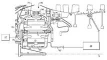
- FIG. 1schematically illustrates a gas turbine engine 20 .
- the gas turbine engine 20is disclosed herein as a two-spool turbofan that generally incorporates a fan section 22 , a compressor section 24 , a combustor section 26 and a turbine section 28 .
- Alternative enginesmight include an augmentor section (not shown) among other systems or features.
- the fan section 22drives air along a bypass flow path B in a bypass duct defined within a nacelle 15
- the compressor section 24drives air along a core flow path C for compression and communication into the combustor section 26 then expansion through the turbine section 28 .
- the exemplary engine 20generally includes a low speed spool 30 and a high speed spool 32 mounted for rotation about an engine central longitudinal axis A relative to an engine static structure 36 via several bearing systems 38 . It should be understood that various bearing systems 38 at various locations may alternatively or additionally be provided, and the location of bearing systems 38 may be varied as appropriate to the application.
- the low speed spool 30generally includes an inner shaft 40 that interconnects a fan 42 , a low pressure compressor 44 and a low pressure turbine 46 .
- the inner shaft 40is connected to the fan 42 through a speed change mechanism, which in exemplary gas turbine engine 20 is illustrated as a geared architecture 48 to drive the fan 42 at a lower speed than the low speed spool 30 .
- the high speed spool 32includes an outer shaft 50 that interconnects a high pressure compressor 52 and high pressure turbine 54 .
- a combustor 56is arranged in exemplary gas turbine 20 between the high pressure compressor 52 and the high pressure turbine 54 .
- a mid-turbine frame 57 of the engine static structure 36is arranged generally between the high pressure turbine 54 and the low pressure turbine 46 .
- the mid-turbine frame 57further supports bearing systems 38 in the turbine section 28 .
- the inner shaft 40 and the outer shaft 50are concentric and rotate via bearing systems 38 about the engine central longitudinal axis A which is collinear with their longitudinal axes.
- the core airflowis compressed by the low pressure compressor 44 then the high pressure compressor 52 , mixed and burned with fuel in the combustor 56 , then expanded over the high pressure turbine 54 and low pressure turbine 46 .
- the mid-turbine frame 57includes airfoils 59 which are in the core airflow path C.
- the turbines 46 , 54rotationally drive the respective low speed spool 30 and high speed spool 32 in response to the expansion.
- gear system 48may be located aft of combustor section 26 or even aft of turbine section 28
- fan section 22may be positioned forward or aft of the location of gear system 48 .
- the engine 20 in one exampleis a high-bypass geared aircraft engine.
- the engine 20 bypass ratiois greater than about six (6), with an example embodiment being greater than about ten (10)
- the geared architecture 48is an epicyclic gear train, such as a planetary gear system or other gear system, with a gear reduction ratio of greater than about 2.3
- the low pressure turbine 46has a pressure ratio that is greater than about five.
- the engine 20 bypass ratiois greater than about ten (10:1)
- the fan diameteris significantly larger than that of the low pressure compressor 44
- the low pressure turbine 46has a pressure ratio that is greater than about five 5:1.
- Low pressure turbine 46 pressure ratiois pressure measured prior to inlet of low pressure turbine 46 as related to the pressure at the outlet of the low pressure turbine 46 prior to an exhaust nozzle.
- the geared architecture 48may be an epicycle gear train, such as a planetary gear system or other gear system, with a gear reduction ratio of greater than about 2.3:1. It should be understood, however, that the above parameters are only exemplary of one embodiment of a geared architecture engine and that the present invention is applicable to other gas turbine engines including direct drive turbofans.
- the fan section 22 of the engine 20is designed for a particular flight condition—typically cruise at about 0.8 Mach and about 35,000 feet.
- TSFCThrust Specific Fuel Consumption
- Low fan pressure ratiois the pressure ratio across the fan blade alone, without a Fan Exit Guide Vane (“FEGV”) system.
- the low fan pressure ratio as disclosed herein according to one non-limiting embodimentis less than about 1.45.
- Low corrected fan tip speedis the actual fan tip speed in ft/sec divided by an industry standard temperature correction of [(Tram ° R) /(518.7° R)] 0.5 .
- the “Low corrected fan tip speed” as disclosed herein according to one non-limiting embodimentis less than about 1150 ft/second.
- the core airflowis compressed by the low pressure compressor 44 then the high pressure compressor 52 , mixed and burned with fuel in the combustor 56 , then expanded over the high pressure turbine 54 and low pressure turbine 46 .
- the turbines 46 , 54rotationally drive the respective low speed spool 30 and high speed spool 32 in response to the expansion of the airflow passing therethrough.
- the amount of thrust that can be produced by a particular turbine section compared to how compact the turbine section is,is referred to as the power density, or the force density, of the turbine section, and is derived by the flat-rated Sea Level Take-Off (SLTO) thrust divided by the volume of the entire turbine section.
- the example volumeis determined from an inlet of the high pressure turbine 54 to an exit of the low pressure turbine 46 .
- each of the low pressure and high pressure turbines 46 , 54is made more compact. That is, the high pressure turbine 54 and the low pressure turbine 46 are made with a shorter axial length, and the spacing between each of the turbines 46 , 54 is decreased, thereby decreasing the volume of the turbine section 28 .
- the power density in the disclosed gas turbine engine 20 including the gear driven fan section 22is greater than those provided in prior art gas turbine engine including a gear driven fan.
- Eight disclosed exemplary engines, which incorporate turbine sections and fan sections driven through a reduction gear system and architectures as set forth in this application,are described in Table I as follows:
- Thrust SLTO Turbine section volumeThrust/turbine section Engine (lbf) from the Inlet volume (lbf/in 3 ) 1 17,000 3,859 4.4 2 23,300 5,330 4.37 3 29,500 6,745 4.37 4 33,000 6,745 4.84 5 96,500 31,086 3.1 6 96,500 62,172 1.55 7 96,500 46,629 2.07 8 37,098 6,745 5.50
- the power densityis greater than or equal to about 1.5 lbf/in 3 . In further embodiments, the power density is greater than or equal to about 2.0 lbf /in 3 . In further embodiments, the power density is greater than or equal to about 3.0 lbf/in 3 . In further embodiments, the power density is greater than or equal to about 4.0 lbf /in 3 . In further embodiments, the power density is less than or equal to about 5.5 lbf /in 3 .
- FIG. 1BWith continued reference to FIG. 1A , relative rotations between components of example disclosed engine architecture 100 are schematically shown.
- the fan 42is connected, through the gearbox 48 , to the low spool 30 to which the low pressure compressor 44 and the low pressure turbine 46 are connected.
- the high pressure compressor 52 and the high pressure turbine 54are connected to a common shaft forming the high spool 32 .
- the high spool 32rotates opposite the direction of rotation of the fan 42 (illustrated in FIG. 1B as the “+” direction.)
- the low spool 30rotates in the same direction as the fan 42 (illustrated in FIG.
- Other relative rotation directions between the two spools and the fancome within the scope of this disclosure.
- One disclosed example speed change device 48has a gear reduction ratio exceeding 2.3:1, meaning that the low pressure turbine 46 turns at least 2.3 times faster than the fan 42 .
- An example disclosed speed change deviceis an epicyclical gearbox of a planet type, where the input is to the center “sun” gear 260 .
- Planet gears 262(only one shown) around the sun gear 260 rotate and are spaced apart by a carrier 264 that rotates in a direction common to the sun gear 260 .
- a ring gear 266which is non-rotatably fixed to the engine static casing 36 (shown in FIG. 1 ), contains the entire gear assembly.
- the fan 42is attached to and driven by the carrier 264 such that the direction of rotation of the fan 42 is the same as the direction of rotation of the carrier 264 that, in turn, is the same as the direction of rotation of the input sun gear 260 . Accordingly, the low pressure compressor 44 and the low pressure turbine 46 counter-rotate relative to the high pressure compressor 52 and the high pressure turbine 54 .
- the mid-turbine frame 57contributes to the overall compactness of the turbine section 28 .
- the airfoil 59 of the mid-turbine frame 57surrounds internal bearing support structures and oil tubes that are cooled. The airfoil 59 also directs flow around the internal bearing support structures and oil tubes for streamlining the high speed exhaust gas flow. Additionally, the airfoil 59 directs flow exiting the high pressure turbine 54 to a proper angle desired to promote increased efficiency of the low pressure turbine 46 .
- Flow exiting the high pressure turbine 54has a significant component of tangential swirl.
- the flow direction exiting the high pressure turbine 54is set almost ideally for the blades in a first stage of the low pressure turbine 46 for a wide range of engine power settings.
- the aerodynamic turning function of the mid turbine frame 57can be efficiently achieved without dramatic additional alignment of airflow exiting the high pressure turbine 54 .
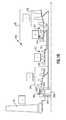
- the example turbine section 28 volumeis schematically shown and includes first, second and third stages 46 A, 46 B and 46 C. Each of the stages 46 A, 46 B and 46 C includes a corresponding plurality of blades 212 and vanes 214 .
- the example turbine sectionfurther includes an example air-turning vane 220 between the low and high turbines 54 , 46 that has a modest camber to provide a small degree of redirection and achieve a desired flow angle relative to blades 212 of the first stage 46 a of the low pressure turbine 46 .
- the disclosed vane 220could not efficiently perform the desired airflow function if the low and high pressure turbines 54 , 46 rotated in a common direction.
- the example mid-turbine frame 57includes multiple air turning vanes 220 in a row that direct air flow exiting the high pressure turbine 54 and ensure that air is flowing in the proper direction and with the proper amount of swirl. Because the disclosed turbine section 28 is more compact than previously utilized turbine sections, air has less distance to travel between exiting the mid-turbine frame 57 and entering the low pressure turbine 46 . The smaller axial travel distance results in a decrease in the amount of swirl lost by the airflow during the transition from the mid-turbine frame 57 to the low pressure turbine 46 , and allows the vanes 220 of the mid-turbine frame 57 to function as inlet guide vanes of the low pressure turbine 46 .
- the mid-turbine frame 57also includes a strut 221 providing structural support to both the mid-turbine frame 57 and to the engine housing.
- the mid-turbine frame 57is much more compact by encasing the strut 221 within the vane 220 , thereby decreasing the length of the mid-turbine frame 57 .
- the inclusion of the speed change device 48provides a gear reduction ratio, and thus the speed of the low pressure turbine 46 and low pressure compressor 44 components may be increased. More specifically, for a given fan diameter and fan tip speed, increases in gear ratios provide for a faster turning turbine that, in turn, provides for an increasingly compact turbine and increased thrust to volume ratios of the turbine section 28 . By increasing the gear reduction ratio, the speed at which the low pressure compressor 44 and the low pressure turbine 46 turn, relative to the speed of the fan 42 , is increased.
- Increases in rotational speeds of the gas turbine engine 20 componentsincreases overall efficiency, thereby providing for reductions in the diameter and the number of stages of the low pressure compressor 44 and the low pressure turbine 46 that would otherwise be required to maintain desired flow characteristics of the air flowing through the core flow path C.
- the axial length of each of the low pressure compressor 44 and the low pressure turbine 46can therefore be further reduced due to efficiencies gained from increased speed provided by an increased gear ratio.
- the reduction in the diameter and the stage count of the turbine section 28increases the compactness and provides for an overall decrease in required axial length of the example gas turbine engine 20 .
- the example turbine section 28(including the high pressure turbine 54 , the mid-turbine frame 57 , and the low pressure turbine 46 ) is made more compact than traditional turbine engine designs, thereby decreasing the length of the turbine section 28 and the overall length of the gas turbine engine 20 .
- Examples of materials and processes within the contemplation of this disclosure for the air-turning vane 220 , the low pressure turbine blades 212 , and the vanes 214include materials with directionally solidified grains to provided added strength in a span-wise direction.
- An example method for creating a vane 220 , 214 or turbine blade 212 having directionally solidified grainscan be found in U.S. application Ser. No. 13/290,667, and U.S. Pat. Nos. 7,338,259 and 7,871,247, each of which is incorporated by reference.
- a further, engine embodimentutilizes a cast, hollow blade 212 or vane 214 with cooling air introduced at the leading edge of the blade/vane and a trailing edge discharge of the cooling air.
- Another embodimentuses an internally cooled blade 212 or vane 214 with film cooling holes.
- An additional engine embodimentutilizes an aluminum lithium material for construction of a portion of the low pressure turbine 46 .
- the example low pressure turbine 46may also be constructed utilizing at a powdered metal disc or rotor.
- one or more rows of turbine blades 212 of the low pressure turbine 46can be constructed using a single crystal blade material.
- Single crystal constructionsoxidize at higher temperatures as compared to non-single crystal constructions and thus can withstand higher temperature airflow.
- Higher temperature capability of the turbine blades 212provide for a more efficient low pressure turbine 46 that may be further reduced in size.
- the low pressure turbine 46includes three turbine stages 46 a, 46 b, and 46 c
- the low pressure turbine 46can be modified to include up to six turbine stages. Increasing the number of low pressure turbine stages 46 a, 46 b, 46 c at constant thrust slightly reduces the thrust density of the turbine section 28 but also increases power available to drive the low pressure compressor and the fan section 22 .
- example turbine bladesmay be internally cooled to allow the material to retain a desired strength at higher temperatures and thereby perform as desired in view of the increased centrifugal force generated by the compact configuration while also withstanding the higher temperatures created by adding low pressure compressor 44 stages and increasing fan tip diameter.
- Each of the disclosed embodimentsenables the low pressure turbine 46 to be more compact and efficient, while also improving radial alignment to the high pressure turbine 54 . Improved radial alignment between the low and high pressure turbines 54 , 46 increases efficiencies that can offset any increases in manufacturing costs incurred by including the air turning vane 220 of the mid-turbine frame 57 .
- the overall size of the turbine section 28has been greatly reduced, thereby enhancing the engine's power density. Further, as a result of the improvement in power density, the engine's overall propulsive efficiency has been improved.
- An exit area 400is shown, in FIG. 1D and FIG. 1A , at the exit location for the high pressure turbine section 54 .
- An exit area for the low pressure turbine sectionis defined at exit 401 for the low pressure turbine section.
- the turbine engine 20may be counter-rotating. This means that the low pressure turbine section 46 and low pressure compressor section 44 rotate in one direction, while the high pressure spool 32 , including high pressure turbine section 54 and high pressure compressor section 52 rotate in an opposed direction.
- the gear reduction 48which may be, for example, an epicyclic transmission (e.g., with a sun, ring, and star gears), is selected such that the fan 42 rotates in the same direction as the high spool 32 .
- a lptis the area of the low pressure turbine section at the exit thereof (e.g., at 401 ), where V lpt is the speed of the low pressure turbine section, where A hpt is the area of the high pressure turbine section at the exit thereof (e.g., at 400 ), and where V hpt is the speed of the low pressure turbine section.
- V lptis the area of the low pressure turbine section at the exit thereof (e.g., at 401 )
- a hptis the area of the high pressure turbine section at the exit thereof (e.g., at 400 )
- V hptis the speed of the low pressure turbine section.
- the areas of the low and high pressure turbine sectionsare 557.9 in 2 and 90.67 in 2 , respectively. Further, the redline speeds of the low and high pressure turbine sections are 10179 rpm and 24346 rpm, respectively.
- the ratiowas about 0.5 and in another embodiment the ratio was about 1.5.
- PQ ltp/ PQ hpt ratios in the 0.5 to 1.5 rangea very efficient overall gas turbine engine is achieved. More narrowly, PQ lpt/ PQ hpt ratios of above or equal to about 0.8 are more efficient. Even more narrowly, PQ ltp/ PQ hpt ratios above or equal to 1.0 are even more efficient.
- the turbine sectioncan be made much smaller than in the prior art, both in diameter and axial length. In addition, the efficiency of the overall engine is greatly increased.
- the low pressure compressor sectionis also improved with this arrangement, and behaves more like a high pressure compressor section than a traditional low pressure compressor section. It is more efficient than the prior art, and can provide more work in fewer stages.
- the low pressure compressor sectionmay be made smaller in radius and shorter in length while contributing more toward achieving the overall pressure ratio design target of the engine.
- the geared architecture 48generally includes a fan drive gear system (FDGS) 60 driven by the low speed spool 30 (illustrated schematically) through an input coupling 62 .
- the input coupling 62both transfers torque from the low speed spool 30 to the geared architecture 48 and facilitates the segregation of vibrations and other transients therebetween.
- the FDGS 60may include an epicyclic gear system which may be, for example, a star system or a planet system.
- the input coupling 62may include an interface spline 64 joined, by a gear spline 66 , to a sun gear 68 of the FDGS 60 .
- the sun gear 68is in meshed engagement with multiple planet gears 70 , of which the illustrated planet gear 70 is representative.
- Each planet gear 70is rotatably mounted in a planet carrier 72 by a respective planet journal bearing 75 .
- Rotary motion of the sun gear 68urges each planet gear 70 to rotate about a respective longitudinal axis P.
- the gearsmay be generally as shown schematically in FIG. 1B .
- Each planet gear 70is also in meshed engagement with rotating ring gear 74 that is mechanically connected to a fan shaft 76 . Since the planet gears 70 mesh with both the rotating ring gear 74 as well as the rotating sun gear 68 , the planet gears 70 rotate about their own axes to drive the ring gear 74 to rotate about engine axis A. The rotation of the ring gear 74 is conveyed to the fan 42 ( FIG. 1 ) through the fan shaft 76 to thereby drive the fan 42 at a lower speed than the low speed spool 30 . It should be understood that the described geared architecture 48 is but a single non-limiting embodiment and that various other geared architectures will alternatively benefit herefrom.
- a flexible support 78supports the planet carrier 72 to at least partially support the FDGS 60 A with respect to the static structure 36 such as a front center body which facilitates the segregation of vibrations and other transients therebetween.
- the static structure 36such as a front center body which facilitates the segregation of vibrations and other transients therebetween.
- various gas turbine engine case structuresmay alternatively or additionally provide the static structure and flexible support 78 .
- the term “lateral” as used hereinrefers to a perpendicular direction with respect to the axis of rotation A and the term “transverse” refers to a pivotal bending movement with respect to the axis of rotation A so as to absorb deflections which may be otherwise applied to the FDGS 60 .
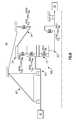
- the static structure 36may further include a number 1 and 1.5 bearing support static structure 82 which is commonly referred to as a “K-frame” which supports the number 1 and number 1.5 bearing systems 38 A. 38 B.
- K-frame bearing supportdefines a lateral stiffness (represented as Kframe in FIG. 3 ) and a transverse stiffness (represented as Kframe BEND in FIG. 3 ) as the referenced factors in this non-limiting embodiment.
- the lateral stiffness (KFS; KIC) of both the flexible support 78 and the input coupling 62are each less than about 11% of the lateral stiffness (Kframe). That is, the lateral stiffness of the entire FDGS 60 is controlled by this lateral stiffness relationship.
- the transverse stiffness of both the flexible support 78 and the input coupling 62are each less than about 11% of the transverse stiffness (Kframe BEND ). That is, the transverse stiffness of the entire FDGS 60 is controlled by this transverse stiffness relationship.
- a FDGS 60 Bincludes a flexible support 78 ′ that supports a rotationally fixed ring gear 74 ′.
- the fan shaft 76 ′is driven by the planet carrier 72 ′ in the schematically illustrated planet system which otherwise generally follows the star system architecture of FIG. 3 .
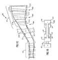
- lateral stiffness relationship within a FDGS 60 C itselfis schematically represented.
- the lateral stiffness (KIC) of an input coupling 62 , a lateral stiffness (KFS) of a flexible support 78 , a lateral stiffness (KRG) of a ring gear 74 and a lateral stiffness (KJB) of a planet journal bearing 75are controlled with respect to a lateral stiffness (KGM) of a gear mesh within the FDGS 60 .
- the stiffness (KGM)may be defined by the gear mesh between the sun gear 68 and the multiple planet gears 70 .
- the lateral stiffness (KGM) within the FDGS 60is the referenced factor and the static structure 82 ′ rigidly supports the fan shaft 76 . That is, the fan shaft 76 is supported upon bearing systems 38 A, 38 B which are essentially rigidly supported by the static structure 82 ′.
- the lateral stiffness (KJB)may be mechanically defined by, for example, the stiffness within the planet journal bearing 75 and the lateral stiffness (KRG) of the ring gear 74 may be mechanically defined by, for example, the geometry of the ring gear wings 74 L, 74 R ( FIG. 2 ).
- the lateral stiffness (KRG) of the ring gear 74is less than about 12% of the lateral stiffness (KGM) of the gear mesh; the lateral stiffness (KFS) of the flexible support 78 is less than about 8% of the lateral stiffness (KGM) of the gear mesh; the lateral stiffness (KJB) of the planet journal bearing 75 is less than or equal to the lateral stiffness (KGM) of the gear mesh; and the lateral stiffness (KIC) of an input coupling 62 is less than about 5% of the lateral stiffness (KGM) of the gear mesh.
- FIG. 6another non-limiting embodiment of a lateral stiffness relationship within a FDGS 60 D itself are schematically illustrated for a planetary gear system architecture, which otherwise generally follows the star system architecture of FIG. 5 .
- lateral stiffness relationshipsmay be utilized as well.
- the lateral stiffness of each of structural componentsmay be readily measured as compared to film stiffness and spline stiffness which may be relatively difficult to determine.
- the flex mountfacilitates alignment to increase system life and reliability.
- the lateral flexibility in the flexible support and input couplingallows the FDGS to essentially ‘float’ with the fan shaft during maneuvers. This allows: (a) the torque transmissions in the fan shaft, the input coupling and the flexible support to remain constant during maneuvers; (b) maneuver induced lateral loads in the fan shaft (which may otherwise potentially misalign gears and damage teeth) to be mainly reacted to through the number 1 and 1.5 bearing support K-frame; and (c) both the flexible support and the input coupling to transmit small amounts of lateral loads into the FDGS.
- the splines, gear tooth stiffness, journal bearings, and ring gear ligamentsare specifically designed to minimize gear tooth stress variations during maneuvers.
- the other connections to the FDGSare flexible mounts (turbine coupling, case flex mount). These mount spring rates have been determined from analysis and proven in rig and flight testing to isolate the gears from engine maneuver loads.
- the planet journal bearing spring ratemay also be controlled to support system flexibility.
- FIG. 7is similar to FIG. 5 but shows the transverse stiffness relationships within the FDGS 60 C (for a star system architecture).
- the transverse stiffness (KIC BEND ) of the input coupling 62 , a transverse stiffness (KFS BEND ) of the flexible support 78 , a transverse stiffness (KRG BEND ) of the ring gear 74 and a transverse stiffness (KJB BEND ) of the planet journal bearing 75are controlled with respect to a transverse stiffness (KGM BEND ) of the gear mesh within the FDGS 60 .
- the stiffness (KGM BEND )may be defined by the gear mesh between the sun gear 68 and the multiple planet gears 70 .
- the transverse stiffness(KGM BEND ) within the FDGS 60is the referenced factor and the static structure 82 ′ rigidly supports the fan shaft 76 . That is, the fan shaft 76 is supported upon bearing systems 38 A, 38 B which are essentially rigidly supported by the static structure 82 ′.
- the transverse stiffness (KJB BEND )may be mechanically defined by, for example, the stiffness within the planet journal bearing 75 and the transverse stiffness (KRG BEND ) of the ring gear 74 may be mechanically defined by, for example, the geometry of the ring gear wings 74 L, 74 R ( FIG. 2 ).
- the transverse stiffness (KRG BEND ) of the ring gear 74is less than about 12% of the transverse stiffness (KGM BEND ) of the gear mesh; the transverse stiffness (KFS BEND ) of the flexible support 78 is less than about 8% of the transverse stiffness (KGM BEND ) of the gear mesh; the transverse stiffness (KJB BEND ) of the planet journal bearing 75 is less than or equal to the transverse stiffness (KGM BEND ) of the gear mesh; and the transverse stiffness (KIC BEND ) of an input coupling 62 is less than about 5% of the transverse stiffness (KGM BEND ) of the gear mesh.
- FIG. 8is similar to FIG. 6 but shows the transverse stiffness relationship within the FDGS 60 D for the planetary gear system architecture.
Landscapes
- Engineering & Computer Science (AREA)
- Mechanical Engineering (AREA)
- General Engineering & Computer Science (AREA)
- Chemical & Material Sciences (AREA)
- Combustion & Propulsion (AREA)
- Retarders (AREA)
- Structures Of Non-Positive Displacement Pumps (AREA)
Abstract
Description
| TABLE 1 | |||
| Thrust SLTO | Turbine section volume | Thrust/turbine section | |
| Engine | (lbf) | from the Inlet | volume (lbf/in3) |
| 1 | 17,000 | 3,859 | 4.4 |
| 2 | 23,300 | 5,330 | 4.37 |
| 3 | 29,500 | 6,745 | 4.37 |
| 4 | 33,000 | 6,745 | 4.84 |
| 5 | 96,500 | 31,086 | 3.1 |
| 6 | 96,500 | 62,172 | 1.55 |
| 7 | 96,500 | 46,629 | 2.07 |
| 8 | 37,098 | 6,745 | 5.50 |
PQltp=(Alpt×Vlpt2) Equation 1:
PQhpt=(Ahpt×Vhpt2) Equation 2:
(Alpt×Vlpt2)/(Ahpt×Vhpt2)=PQltp/PQhpt Equation 3:
PQltp=(Alpt×Vipt2)=(557.9in2)(10179 rpm)2=57805157673.9in2rpm2 Equation 1:
PQhpt=(Ahpt×Vhpt2)=(90.67in2)(24346 rpm)2=53742622009.72in2rpm2 Equation 2:
and using Equation 3 above, the ratio for the low pressure turbine section to the high pressure turbine section is:
Ratio=PQltp/PQhpt=57805157673.9in2rpm2/53742622009.72in2rpm2=1.075
Claims (20)
Priority Applications (31)
| Application Number | Priority Date | Filing Date | Title |
|---|---|---|---|
| US13/908,177US9631558B2 (en) | 2012-01-03 | 2013-06-03 | Geared architecture for high speed and small volume fan drive turbine |
| US13/974,136US8747055B2 (en) | 2011-06-08 | 2013-08-23 | Geared architecture for high speed and small volume fan drive turbine |
| EP23160056.0AEP4209661A3 (en) | 2013-06-03 | 2014-02-17 | Geared architecture for high speed and small volume fan drive turbine |
| EP18191325.2AEP3467272A1 (en) | 2013-06-03 | 2014-02-17 | Geared architecture for high speed and small volume fan drive turbine |
| EP18191333.6AEP3467273A1 (en) | 2013-06-03 | 2014-02-17 | Geared architecture for high speed and small volume fan drive turbine |
| EP14155460.0AEP2811120B1 (en) | 2013-06-03 | 2014-02-17 | Geared architecture for high speed and small volume fan drive turbine |
| EP15175205.2AEP2949882B1 (en) | 2013-06-03 | 2014-02-17 | Geared architecture for high speed and small volume fan drive turbine |
| EP15175203.7AEP2949881B1 (en) | 2013-06-03 | 2014-02-17 | Geared architecture for high speed and small volume fan drive turbine |
| JP2014042229AJP5732562B2 (en) | 2013-06-03 | 2014-03-05 | Gas turbine engine |
| CN201410082009.1ACN104213985B (en) | 2013-06-03 | 2014-03-07 | For gear drive framework at a high speed with small size fans drive turbine |
| CA2845618ACA2845618C (en) | 2013-06-03 | 2014-03-10 | Geared architecture for high speed and small volume fan drive turbine |
| RU2014110925ARU2639821C2 (en) | 2013-06-03 | 2014-03-24 | Reduction gear for high-speed and small-size fan drive turbine |
| BR102014007285-3ABR102014007285B1 (en) | 2013-06-03 | 2014-03-26 | GAS TURBINE ENGINE |
| SG10201401514UASG10201401514UA (en) | 2013-06-03 | 2014-04-14 | Geared architecture for high speed and small volume fan drive turbine |
| US14/260,557US8899915B2 (en) | 2011-06-08 | 2014-04-24 | Geared architecture for high speed and small volume fan drive turbine |
| US15/437,104US20170159572A1 (en) | 2011-06-08 | 2017-02-20 | Geared Architecture for High Speed and Small Volume Fan Drive Turbine |
| US15/440,412US20170306855A1 (en) | 2011-06-08 | 2017-02-23 | Geared Architecture for High Speed and Small Volume Fan Drive Turbine |
| US15/484,441US9752511B2 (en) | 2011-06-08 | 2017-04-11 | Geared architecture for high speed and small volume fan drive turbine |
| US15/485,512US11047337B2 (en) | 2011-06-08 | 2017-04-12 | Geared architecture for high speed and small volume fan drive turbine |
| US15/485,563US20170218850A1 (en) | 2011-06-08 | 2017-04-12 | Geared Architecture for High Speed and Small Volume Fan Drive Turbine |
| US15/485,312US20170226935A1 (en) | 2011-06-08 | 2017-04-12 | Geared Architecture for High Speed and Small Volume Fan Drive Turbine |
| US15/606,522US20170276010A1 (en) | 2011-06-08 | 2017-05-26 | Geared architecture for high speed and small volume fan drive turbine |
| US15/606,386US20170276009A1 (en) | 2011-06-08 | 2017-05-26 | Geared architecture for high speed and small volume fan drive turbine |
| US15/638,954US20170298757A1 (en) | 2011-06-08 | 2017-06-30 | Geared architecture for high speed and small volume fan drive turbine |
| US15/816,512US20180094532A1 (en) | 2011-06-08 | 2017-11-17 | Geared architecture for high speed and small volume fan drive turbine |
| US15/856,396US20180135454A1 (en) | 2011-06-08 | 2017-12-28 | Geared architecture for high speed and small volume fan drive turbine |
| US15/856,441US20180119564A1 (en) | 2011-06-08 | 2017-12-28 | Geared architecture for high speed and small volume fan drive turbine |
| US15/856,421US20180119563A1 (en) | 2011-06-08 | 2017-12-28 | Geared architecture for high speed and small volume fan drive turbine |
| US15/881,240US11073106B2 (en) | 2011-06-08 | 2018-01-26 | Geared architecture for high speed and small volume fan drive turbine |
| US17/342,100US11635043B2 (en) | 2011-06-08 | 2021-06-08 | Geared architecture for high speed and small volume fan drive turbine |
| US18/130,539US20230235715A1 (en) | 2011-06-08 | 2023-04-04 | Geared architecture for high speed and small volume fan drive turbine |
Applications Claiming Priority (3)
| Application Number | Priority Date | Filing Date | Title |
|---|---|---|---|
| US13/342,508US8297916B1 (en) | 2011-06-08 | 2012-01-03 | Flexible support structure for a geared architecture gas turbine engine |
| US13/623,309US9133729B1 (en) | 2011-06-08 | 2012-09-20 | Flexible support structure for a geared architecture gas turbine engine |
| US13/908,177US9631558B2 (en) | 2012-01-03 | 2013-06-03 | Geared architecture for high speed and small volume fan drive turbine |
Related Parent Applications (1)
| Application Number | Title | Priority Date | Filing Date |
|---|---|---|---|
| US13/623,309Continuation-In-PartUS9133729B1 (en) | 2011-06-08 | 2012-09-20 | Flexible support structure for a geared architecture gas turbine engine |
Related Child Applications (7)
| Application Number | Title | Priority Date | Filing Date |
|---|---|---|---|
| US13/974,136ContinuationUS8747055B2 (en) | 2011-06-08 | 2013-08-23 | Geared architecture for high speed and small volume fan drive turbine |
| US15/437,104ContinuationUS20170159572A1 (en) | 2011-06-08 | 2017-02-20 | Geared Architecture for High Speed and Small Volume Fan Drive Turbine |
| US15/440,412ContinuationUS20170306855A1 (en) | 2011-06-08 | 2017-02-23 | Geared Architecture for High Speed and Small Volume Fan Drive Turbine |
| US15/484,441ContinuationUS9752511B2 (en) | 2011-06-08 | 2017-04-11 | Geared architecture for high speed and small volume fan drive turbine |
| US15/485,563ContinuationUS20170218850A1 (en) | 2011-06-08 | 2017-04-12 | Geared Architecture for High Speed and Small Volume Fan Drive Turbine |
| US15/485,312ContinuationUS20170226935A1 (en) | 2011-06-08 | 2017-04-12 | Geared Architecture for High Speed and Small Volume Fan Drive Turbine |
| US15/485,512ContinuationUS11047337B2 (en) | 2011-06-08 | 2017-04-12 | Geared architecture for high speed and small volume fan drive turbine |
Publications (2)
| Publication Number | Publication Date |
|---|---|
| US20130287575A1 US20130287575A1 (en) | 2013-10-31 |
| US9631558B2true US9631558B2 (en) | 2017-04-25 |
Family
ID=49477451
Family Applications (18)
| Application Number | Title | Priority Date | Filing Date |
|---|---|---|---|
| US13/908,177Active2034-04-18US9631558B2 (en) | 2011-06-08 | 2013-06-03 | Geared architecture for high speed and small volume fan drive turbine |
| US13/974,136ActiveUS8747055B2 (en) | 2011-06-08 | 2013-08-23 | Geared architecture for high speed and small volume fan drive turbine |
| US14/260,557ActiveUS8899915B2 (en) | 2011-06-08 | 2014-04-24 | Geared architecture for high speed and small volume fan drive turbine |
| US15/437,104AbandonedUS20170159572A1 (en) | 2011-06-08 | 2017-02-20 | Geared Architecture for High Speed and Small Volume Fan Drive Turbine |
| US15/440,412AbandonedUS20170306855A1 (en) | 2011-06-08 | 2017-02-23 | Geared Architecture for High Speed and Small Volume Fan Drive Turbine |
| US15/484,441ActiveUS9752511B2 (en) | 2011-06-08 | 2017-04-11 | Geared architecture for high speed and small volume fan drive turbine |
| US15/485,563AbandonedUS20170218850A1 (en) | 2011-06-08 | 2017-04-12 | Geared Architecture for High Speed and Small Volume Fan Drive Turbine |
| US15/485,512Active2032-07-09US11047337B2 (en) | 2011-06-08 | 2017-04-12 | Geared architecture for high speed and small volume fan drive turbine |
| US15/485,312AbandonedUS20170226935A1 (en) | 2011-06-08 | 2017-04-12 | Geared Architecture for High Speed and Small Volume Fan Drive Turbine |
| US15/606,386AbandonedUS20170276009A1 (en) | 2011-06-08 | 2017-05-26 | Geared architecture for high speed and small volume fan drive turbine |
| US15/606,522AbandonedUS20170276010A1 (en) | 2011-06-08 | 2017-05-26 | Geared architecture for high speed and small volume fan drive turbine |
| US15/638,954AbandonedUS20170298757A1 (en) | 2011-06-08 | 2017-06-30 | Geared architecture for high speed and small volume fan drive turbine |
| US15/816,512AbandonedUS20180094532A1 (en) | 2011-06-08 | 2017-11-17 | Geared architecture for high speed and small volume fan drive turbine |
| US15/856,441AbandonedUS20180119564A1 (en) | 2011-06-08 | 2017-12-28 | Geared architecture for high speed and small volume fan drive turbine |
| US15/856,421AbandonedUS20180119563A1 (en) | 2011-06-08 | 2017-12-28 | Geared architecture for high speed and small volume fan drive turbine |
| US15/856,396AbandonedUS20180135454A1 (en) | 2011-06-08 | 2017-12-28 | Geared architecture for high speed and small volume fan drive turbine |
| US15/881,240ActiveUS11073106B2 (en) | 2011-06-08 | 2018-01-26 | Geared architecture for high speed and small volume fan drive turbine |
| US17/342,100ActiveUS11635043B2 (en) | 2011-06-08 | 2021-06-08 | Geared architecture for high speed and small volume fan drive turbine |
Family Applications After (17)
| Application Number | Title | Priority Date | Filing Date |
|---|---|---|---|
| US13/974,136ActiveUS8747055B2 (en) | 2011-06-08 | 2013-08-23 | Geared architecture for high speed and small volume fan drive turbine |
| US14/260,557ActiveUS8899915B2 (en) | 2011-06-08 | 2014-04-24 | Geared architecture for high speed and small volume fan drive turbine |
| US15/437,104AbandonedUS20170159572A1 (en) | 2011-06-08 | 2017-02-20 | Geared Architecture for High Speed and Small Volume Fan Drive Turbine |
| US15/440,412AbandonedUS20170306855A1 (en) | 2011-06-08 | 2017-02-23 | Geared Architecture for High Speed and Small Volume Fan Drive Turbine |
| US15/484,441ActiveUS9752511B2 (en) | 2011-06-08 | 2017-04-11 | Geared architecture for high speed and small volume fan drive turbine |
| US15/485,563AbandonedUS20170218850A1 (en) | 2011-06-08 | 2017-04-12 | Geared Architecture for High Speed and Small Volume Fan Drive Turbine |
| US15/485,512Active2032-07-09US11047337B2 (en) | 2011-06-08 | 2017-04-12 | Geared architecture for high speed and small volume fan drive turbine |
| US15/485,312AbandonedUS20170226935A1 (en) | 2011-06-08 | 2017-04-12 | Geared Architecture for High Speed and Small Volume Fan Drive Turbine |
| US15/606,386AbandonedUS20170276009A1 (en) | 2011-06-08 | 2017-05-26 | Geared architecture for high speed and small volume fan drive turbine |
| US15/606,522AbandonedUS20170276010A1 (en) | 2011-06-08 | 2017-05-26 | Geared architecture for high speed and small volume fan drive turbine |
| US15/638,954AbandonedUS20170298757A1 (en) | 2011-06-08 | 2017-06-30 | Geared architecture for high speed and small volume fan drive turbine |
| US15/816,512AbandonedUS20180094532A1 (en) | 2011-06-08 | 2017-11-17 | Geared architecture for high speed and small volume fan drive turbine |
| US15/856,441AbandonedUS20180119564A1 (en) | 2011-06-08 | 2017-12-28 | Geared architecture for high speed and small volume fan drive turbine |
| US15/856,421AbandonedUS20180119563A1 (en) | 2011-06-08 | 2017-12-28 | Geared architecture for high speed and small volume fan drive turbine |
| US15/856,396AbandonedUS20180135454A1 (en) | 2011-06-08 | 2017-12-28 | Geared architecture for high speed and small volume fan drive turbine |
| US15/881,240ActiveUS11073106B2 (en) | 2011-06-08 | 2018-01-26 | Geared architecture for high speed and small volume fan drive turbine |
| US17/342,100ActiveUS11635043B2 (en) | 2011-06-08 | 2021-06-08 | Geared architecture for high speed and small volume fan drive turbine |
Country Status (1)
| Country | Link |
|---|---|
| US (18) | US9631558B2 (en) |
Cited By (20)
| Publication number | Priority date | Publication date | Assignee | Title |
|---|---|---|---|---|
| US20150377143A1 (en)* | 2013-03-12 | 2015-12-31 | United Technologies Corporation | Flexible coupling for geared turbine engine |
| US10119465B2 (en) | 2015-06-23 | 2018-11-06 | United Technologies Corporation | Geared turbofan with independent flexible ring gears and oil collectors |
| US10240526B2 (en) | 2012-01-31 | 2019-03-26 | United Technologies Corporation | Gas turbine engine with high speed low pressure turbine section |
| US10288011B2 (en) | 2012-01-31 | 2019-05-14 | United Technologies Corporation | Geared turbofan gas turbine engine architecture |
| US10539222B2 (en) | 2011-06-08 | 2020-01-21 | United Technologies Corporation | Flexible support structure for a geared architecture gas turbine engine |
| US10794292B2 (en) | 2012-01-31 | 2020-10-06 | United Technologies Corporation | Geared turbofan gas turbine engine architecture |
| US10815881B2 (en) | 2017-09-20 | 2020-10-27 | General Electric Company | Counter rotating turbine with reversing speed reduction assembly |
| US10823004B2 (en)* | 2018-03-20 | 2020-11-03 | Rolls-Royce Deutschland Ltd & Co Kg | Geared turbofan engine and spline arrangement |
| US10830130B2 (en) | 2012-04-25 | 2020-11-10 | Raytheon Technologies Corporation | Geared turbofan with three turbines all counter-rotating |
| US11021996B2 (en) | 2011-06-08 | 2021-06-01 | Raytheon Technologies Corporation | Flexible support structure for a geared architecture gas turbine engine |
| US11047337B2 (en) | 2011-06-08 | 2021-06-29 | Raytheon Technologies Corporation | Geared architecture for high speed and small volume fan drive turbine |
| US11053843B2 (en) | 2012-04-02 | 2021-07-06 | Raytheon Technologies Corporation | Geared turbofan engine with a high ratio of thrust to turbine volume |
| EP3882490A1 (en) | 2020-03-16 | 2021-09-22 | Flender GmbH | Spur gear assembly with improved centring |
| US11428160B2 (en) | 2020-12-31 | 2022-08-30 | General Electric Company | Gas turbine engine with interdigitated turbine and gear assembly |
| US11585276B2 (en) | 2012-01-31 | 2023-02-21 | Raytheon Technologies Corporation | Gas turbine engine with high speed low pressure turbine section and bearing support features |
| US11608786B2 (en) | 2012-04-02 | 2023-03-21 | Raytheon Technologies Corporation | Gas turbine engine with power density range |
| US11913349B2 (en) | 2012-01-31 | 2024-02-27 | Rtx Corporation | Gas turbine engine with high speed low pressure turbine section and bearing support features |
| US12203418B2 (en) | 2022-04-25 | 2025-01-21 | General Electric Company | Mounting assembly for a gearbox assembly |
| US12281618B2 (en) | 2022-04-25 | 2025-04-22 | General Electric Company | Mounting assembly for a gearbox assembly |
| US12385443B2 (en) | 2022-04-25 | 2025-08-12 | General Electric Company | Mounting assembly for a gearbox assembly |
Families Citing this family (72)
| Publication number | Priority date | Publication date | Assignee | Title |
|---|---|---|---|---|
| US9976437B2 (en) | 2006-08-15 | 2018-05-22 | United Technologies Corporation | Epicyclic gear train |
| US8753243B2 (en) | 2006-08-15 | 2014-06-17 | United Technologies Corporation | Ring gear mounting arrangement with oil scavenge scheme |
| US10107231B2 (en)* | 2006-08-15 | 2018-10-23 | United Technologies Corporation | Gas turbine engine with geared architecture |
| US20230235715A1 (en)* | 2011-06-08 | 2023-07-27 | Raytheon Technologies Corporation | Geared architecture for high speed and small volume fan drive turbine |
| US9222417B2 (en)* | 2012-01-31 | 2015-12-29 | United Technologies Corporation | Geared turbofan gas turbine engine architecture |
| US10309232B2 (en)* | 2012-02-29 | 2019-06-04 | United Technologies Corporation | Gas turbine engine with stage dependent material selection for blades and disk |
| US8572943B1 (en) | 2012-05-31 | 2013-11-05 | United Technologies Corporation | Fundamental gear system architecture |
| WO2014055114A1 (en)* | 2012-10-02 | 2014-04-10 | United Technologies Corporation | Geared turbofan engine with high compressor exit temperature |
| US10036316B2 (en)* | 2012-10-02 | 2018-07-31 | United Technologies Corporation | Geared turbofan engine with high compressor exit temperature |
| EP2811120B1 (en) | 2013-06-03 | 2017-07-12 | United Technologies Corporation | Geared architecture for high speed and small volume fan drive turbine |
| WO2015156885A2 (en)* | 2014-01-22 | 2015-10-15 | United Technologies Corporation | Flexible support structure for a geared architecture gas turbine engine |
| US9850814B2 (en) | 2014-02-19 | 2017-12-26 | United Technologies Corporation | Annular spring for a bearing assembly of a gas turbine engine |
| US10077660B2 (en)* | 2014-12-03 | 2018-09-18 | General Electric Company | Turbine engine assembly and method of manufacturing |
| US10094335B2 (en) | 2015-12-07 | 2018-10-09 | General Electric Company | Compliant shaft with a recursive configuration for turbine engines |
| US10830066B2 (en)* | 2016-01-05 | 2020-11-10 | Safran Aircraft Engines | Low-pitch variable-setting fan of a turbine engine |
| US20170342839A1 (en)* | 2016-05-25 | 2017-11-30 | General Electric Company | System for a low swirl low pressure turbine |
| US20180002025A1 (en)* | 2016-07-01 | 2018-01-04 | United Technologies Corporation | Aircraft including parallel hybrid gas turbine electric propulsion system |
| US10669947B2 (en) | 2016-07-11 | 2020-06-02 | Raytheon Technologies Corporation | Geared gas turbine engine |
| US11346288B2 (en)* | 2016-09-21 | 2022-05-31 | Raytheon Technologies Corporation | Gas turbine engine with heat exchanger diagnostics |
| US9745860B1 (en)* | 2016-11-02 | 2017-08-29 | Jay HASKIN | Power transmission system for turbine or compressor having counter-rotating blades |
| US10746047B2 (en) | 2017-10-27 | 2020-08-18 | General Electric Company | Structure for mitigating vibratory modes of counter-rotating engine rotors |
| US11725584B2 (en) | 2018-01-17 | 2023-08-15 | General Electric Company | Heat engine with heat exchanger |
| FR3079550B1 (en)* | 2018-03-27 | 2020-10-23 | Safran Aircraft Engines | TURBINE SHAFT OF A TURBOMACHINE AND PROCESS FOR PROTECTING AGAINST OVERSPEED OF THE SHAFT |
| IT201800005822A1 (en) | 2018-05-29 | 2019-11-29 | ATTACHMENT OF A GEAR GROUP FOR A GAS TURBINE ENGINE | |
| FR3088967B1 (en)* | 2018-11-27 | 2020-11-06 | Safran Aircraft Engines | Double-flow turbojet arrangement with epicyclic or planetary reduction gear |
| GB201917773D0 (en) | 2019-12-05 | 2020-01-22 | Rolls Royce Plc | High power epicyclic gearbox and operation thereof |
| GB201908972D0 (en) | 2019-06-24 | 2019-08-07 | Rolls Royce Plc | Compression in a gas turbine engine |
| GB201908978D0 (en) | 2019-06-24 | 2019-08-07 | Rolls Royce Plc | Gas turbine engine transfer efficiency |
| GB201917759D0 (en)* | 2019-12-05 | 2020-01-22 | Rolls Royce Plc | High power epicyclic gearbox and operation thereof |
| GB201917765D0 (en)* | 2019-12-05 | 2020-01-22 | Rolls Royce Plc | Aircraft engine |
| GB201917761D0 (en)* | 2019-12-05 | 2020-01-22 | Rolls Royce Plc | Reliable gearbox for gas turbine engine |
| GB201917776D0 (en)* | 2019-12-05 | 2020-01-22 | Rolls Royce Plc | Aircraft engine |
| US12297779B2 (en) | 2019-12-05 | 2025-05-13 | Rolls-Royce Plc | Geared gas turbine engine |
| GB201917774D0 (en)* | 2019-12-05 | 2020-01-22 | Rolls Royce Plc | Gas turbine engine arrangement |
| GB201917763D0 (en)* | 2019-12-05 | 2020-01-22 | Rolls Royce Plc | Gas turbine engine arrangement |
| GB201917766D0 (en)* | 2019-12-05 | 2020-01-22 | Rolls Royce Plc | Geared gas turbine engine |
| GB201917767D0 (en)* | 2019-12-05 | 2020-01-22 | Rolls Royce Plc | High power epicyclic gearbox and operation thereof |
| GB201917772D0 (en)* | 2019-12-05 | 2020-01-22 | Rolls Royce Plc | Aircraft engine |
| GB201917760D0 (en) | 2019-12-05 | 2020-01-22 | Rolls Royce Plc | Aircraft engine |
| GB201917762D0 (en)* | 2019-12-05 | 2020-01-22 | Rolls Royce Plc | Reliable gearbox for gas turbine engine |
| GB201917781D0 (en) | 2019-12-05 | 2020-01-22 | Rolls Royce Plc | Reliable gearbox for gas turbine engine |
| GB201917782D0 (en)* | 2019-12-05 | 2020-01-22 | Rolls Royce Plc | High power epicyclic gearbox and operation thereof |
| GB201917783D0 (en)* | 2019-12-05 | 2020-01-22 | Rolls Royce Plc | Geared gas turbine engine |
| GB201917769D0 (en)* | 2019-12-05 | 2020-01-22 | Rolls Royce Plc | Geared gas turbine engine |
| GB201917779D0 (en)* | 2019-12-05 | 2020-01-22 | Rolls Royce Plc | Aircraft engine |
| GB201917777D0 (en) | 2019-12-05 | 2020-01-22 | Rolls Royce Plc | High power epicyclic gearbox and operation thereof |
| GB201917764D0 (en) | 2019-12-05 | 2020-01-22 | Rolls Royce Plc | Reliable gearbox for gas turbine engine |
| GB201917770D0 (en)* | 2019-12-05 | 2020-01-22 | Rolls Royce Plc | Reliable gearbox for gas turine engine |
| WO2022081606A1 (en) | 2020-10-13 | 2022-04-21 | Venture Aerospace, Llc | Aerospace structure methods of manufacturing |
| US20220213802A1 (en) | 2021-01-06 | 2022-07-07 | General Electric Company | System for controlling blade clearances within a gas turbine engine |
| US11434824B2 (en) | 2021-02-03 | 2022-09-06 | General Electric Company | Fuel heater and energy conversion system |
| US11788470B2 (en) | 2021-03-01 | 2023-10-17 | General Electric Company | Gas turbine engine thermal management |
| US11591965B2 (en) | 2021-03-29 | 2023-02-28 | General Electric Company | Thermal management system for transferring heat between fluids |
| IT202100018935A1 (en)* | 2021-07-16 | 2023-01-16 | Ge Avio Srl | DAMPER SYSTEM FOR AN ENGINE SHAFT |
| US11674396B2 (en) | 2021-07-30 | 2023-06-13 | General Electric Company | Cooling air delivery assembly |
| US11920500B2 (en) | 2021-08-30 | 2024-03-05 | General Electric Company | Passive flow modulation device |
| FR3127024B1 (en)* | 2021-09-10 | 2024-03-08 | Safran Aircraft Engines | Flexibilities in a gearbox turbomachine |
| US12410752B2 (en) | 2021-09-23 | 2025-09-09 | General Electric Company | System and method of detecting an airflow fault condition |
| US11702958B2 (en) | 2021-09-23 | 2023-07-18 | General Electric Company | System and method of regulating thermal transport bus pressure |
| US20230257128A1 (en) | 2022-02-11 | 2023-08-17 | Pratt & Whitney Canada Corp. | Hybrid-Electric Aircraft Propulsion System and Method for Operating the Same |
| US11692448B1 (en) | 2022-03-04 | 2023-07-04 | General Electric Company | Passive valve assembly for a nozzle of a gas turbine engine |
| US20240068557A1 (en)* | 2022-08-23 | 2024-02-29 | Rolls-Royce Deutschland Ltd & Co Kg | Bearing arrangement and epicyclic gearbox with elastic elements |
| US12428992B2 (en) | 2022-11-01 | 2025-09-30 | General Electric Company | Gas turbine engine |
| US12410753B2 (en) | 2022-11-01 | 2025-09-09 | General Electric Company | Gas turbine engine |
| US12196131B2 (en) | 2022-11-01 | 2025-01-14 | General Electric Company | Gas turbine engine |
| US12392290B2 (en) | 2022-11-01 | 2025-08-19 | General Electric Company | Gas turbine engine |
| US20240159608A1 (en)* | 2022-11-16 | 2024-05-16 | General Electric Company | System and method for determining torque in a turbomachine |
| US12168960B2 (en) | 2023-05-15 | 2024-12-17 | General Electric Company | Gas turbine engine |
| US20250042559A1 (en) | 2023-08-01 | 2025-02-06 | Pratt & Whitney Canada Corp. | Aircraft propulsion system with engine ratings as a function of system components |
| US12209557B1 (en) | 2023-11-30 | 2025-01-28 | General Electric Company | Gas turbine engine with forward swept outlet guide vanes |
| US12385430B2 (en) | 2023-11-30 | 2025-08-12 | General Electric Company | Gas turbine engine with forward swept outlet guide vanes |
| US12291997B1 (en) | 2024-04-30 | 2025-05-06 | General Electric Company | Variable area turbine nozzle assembly |
Citations (188)
| Publication number | Priority date | Publication date | Assignee | Title |
|---|---|---|---|---|
| US2608821A (en) | 1949-10-08 | 1952-09-02 | Gen Electric | Contrarotating turbojet engine having independent bearing supports for each turbocompressor |
| US2748623A (en) | 1952-02-05 | 1956-06-05 | Boeing Co | Orbit gear controlled reversible planetary transmissions |
| US2936655A (en) | 1955-11-04 | 1960-05-17 | Gen Motors Corp | Self-aligning planetary gearing |
| US3021731A (en) | 1951-11-10 | 1962-02-20 | Wilhelm G Stoeckicht | Planetary gear transmission |
| US3033002A (en) | 1957-11-08 | 1962-05-08 | Fairfield Shipbuilding And Eng | Marine propulsion steam turbine installations |
| US3111005A (en) | 1963-11-19 | Jet propulsion plant | ||
| US3185857A (en) | 1960-02-01 | 1965-05-25 | Lear Siegler Inc | Control apparatus for the parallel operation of alternators |
| US3287906A (en) | 1965-07-20 | 1966-11-29 | Gen Motors Corp | Cooled gas turbine vanes |
| US3352178A (en) | 1965-11-15 | 1967-11-14 | Gen Motors Corp | Planetary gearing |
| US3526092A (en) | 1967-09-15 | 1970-09-01 | Rolls Royce | Gas turbine engine having improved bearing support means for concentric shafts |
| US3729957A (en) | 1971-01-08 | 1973-05-01 | Secr Defence | Fan |
| US3747343A (en) | 1972-02-10 | 1973-07-24 | United Aircraft Corp | Low noise prop-fan |
| US3754484A (en) | 1971-01-08 | 1973-08-28 | Secr Defence | Gearing |
| US3861139A (en) | 1973-02-12 | 1975-01-21 | Gen Electric | Turbofan engine having counterrotating compressor and turbine elements and unique fan disposition |
| US3892358A (en) | 1971-03-17 | 1975-07-01 | Gen Electric | Nozzle seal |
| GB1516041A (en) | 1977-02-14 | 1978-06-28 | Secr Defence | Multistage axial flow compressor stators |
| US4130872A (en) | 1975-10-10 | 1978-12-19 | The United States Of America As Represented By The Secretary Of The Air Force | Method and system of controlling a jet engine for avoiding engine surge |
| US4136286A (en) | 1977-07-05 | 1979-01-23 | Woodward Governor Company | Isolated electrical power generation system with multiple isochronous, load-sharing engine-generator units |
| GB2041090A (en) | 1979-01-31 | 1980-09-03 | Rolls Royce | By-pass gas turbine engines |
| US4233555A (en) | 1979-04-05 | 1980-11-11 | Dyna Technology, Inc. | Alternating current generator for providing three phase and single phase power at different respective voltages |
| US4405892A (en) | 1979-07-19 | 1983-09-20 | Brunswick Corporation | Regulator for a generator energized battery |
| US4463553A (en) | 1981-05-29 | 1984-08-07 | Office National D'etudes Et De Recherches Aerospatiales | Turbojet with contrarotating wheels |
| US4660376A (en) | 1984-04-27 | 1987-04-28 | General Electric Company | Method for operating a fluid injection gas turbine engine |
| EP0253548A2 (en) | 1986-07-15 | 1988-01-20 | Savyon Diagnostics Ltd. | Method for the determination of occult blood and chemical compositions therefor |
| US4808076A (en) | 1987-12-15 | 1989-02-28 | United Technologies Corporation | Rotor for a gas turbine engine |
| US4809498A (en) | 1987-07-06 | 1989-03-07 | General Electric Company | Gas turbine engine |
| US4827712A (en) | 1986-12-23 | 1989-05-09 | Rolls-Royce Plc | Turbofan gas turbine engine |
| US4879624A (en) | 1987-12-24 | 1989-11-07 | Sundstrand Corporation | Power controller |
| US5074109A (en) | 1989-03-22 | 1991-12-24 | Societe Nationale D'etude Et De Construction De Moteurs D'aviation "S.N.E.C.M.A." | Low pressure turbine rotor suspension in a twin hub turbo-engine |
| US5081832A (en) | 1990-03-05 | 1992-01-21 | Rolf Jan Mowill | High efficiency, twin spool, radial-high pressure, gas turbine engine |
| US5160251A (en) | 1991-05-13 | 1992-11-03 | General Electric Company | Lightweight engine turbine bearing support assembly for withstanding radial and axial loads |
| US5168208A (en) | 1988-05-09 | 1992-12-01 | Onan Corporation | Microprocessor based integrated generator set controller apparatus and method |
| US5182464A (en) | 1991-01-09 | 1993-01-26 | Techmatics, Inc. | High speed transfer switch |
| US5252905A (en) | 1985-12-23 | 1993-10-12 | York International Corporation | Driving system for single phase A-C induction motor |
| US5307622A (en) | 1993-08-02 | 1994-05-03 | General Electric Company | Counterrotating turbine support assembly |
| US5388964A (en) | 1993-09-14 | 1995-02-14 | General Electric Company | Hybrid rotor blade |
| US5433674A (en)* | 1994-04-12 | 1995-07-18 | United Technologies Corporation | Coupling system for a planetary gear train |
| US5447411A (en) | 1993-06-10 | 1995-09-05 | Martin Marietta Corporation | Light weight fan blade containment system |
| US5524847A (en) | 1993-09-07 | 1996-06-11 | United Technologies Corporation | Nacelle and mounting arrangement for an aircraft engine |
| US5625276A (en) | 1994-09-14 | 1997-04-29 | Coleman Powermate, Inc. | Controller for permanent magnet generator |
| US5694027A (en) | 1994-12-08 | 1997-12-02 | Satake Corporation | Three-phase brushless self-excited synchronous generator with no rotor excitation windings |
| US5729059A (en) | 1995-06-07 | 1998-03-17 | Kilroy; Donald G. | Digital no-break power transfer system |
| US5734255A (en) | 1996-03-13 | 1998-03-31 | Alaska Power Systems Inc. | Control system and circuits for distributed electrical power generating stations |
| US5740668A (en) | 1994-04-20 | 1998-04-21 | Hitachi, Ltd. | High efficiency gas turbine |
| US5754033A (en) | 1996-03-13 | 1998-05-19 | Alaska Power Systems Inc. | Control system and circuits for distributed electrical-power generating stations |
| US5778659A (en) | 1994-10-20 | 1998-07-14 | United Technologies Corporation | Variable area fan exhaust nozzle having mechanically separate sleeve and thrust reverser actuation systems |
| US5806303A (en) | 1996-03-29 | 1998-09-15 | General Electric Company | Turbofan engine with a core driven supercharged bypass duct and fixed geometry nozzle |
| US5857836A (en) | 1996-09-10 | 1999-01-12 | Aerodyne Research, Inc. | Evaporatively cooled rotor for a gas turbine engine |
| US5886890A (en) | 1996-06-24 | 1999-03-23 | Sanyo Electric Co., Ltd. | Power-supply system involving system interconnection |
| US5915917A (en) | 1994-12-14 | 1999-06-29 | United Technologies Corporation | Compressor stall and surge control using airflow asymmetry measurement |
| US5949153A (en) | 1997-03-06 | 1999-09-07 | Consolidated Natural Gas Service Company, Inc. | Multi-engine controller |
| US5975841A (en) | 1997-10-03 | 1999-11-02 | Thermal Corp. | Heat pipe cooling for turbine stators |
| US6073439A (en)* | 1997-03-05 | 2000-06-13 | Rolls-Royce Plc | Ducted fan gas turbine engine |
| US6104171A (en) | 1998-11-23 | 2000-08-15 | Caterpillar Inc. | Generator set with redundant bus sensing and automatic generator on-line control |
| US6209311B1 (en) | 1998-04-13 | 2001-04-03 | Nikkiso Company, Ltd. | Turbofan engine including fans with reduced speed |
| US6223616B1 (en) | 1999-12-22 | 2001-05-01 | United Technologies Corporation | Star gear system with lubrication circuit and lubrication method therefor |
| US6260351B1 (en) | 1998-12-10 | 2001-07-17 | United Technologies Corporation | Controlled spring rate gearbox mount |
| US6318070B1 (en) | 2000-03-03 | 2001-11-20 | United Technologies Corporation | Variable area nozzle for gas turbine engines driven by shape memory alloy actuators |
| US6339927B1 (en) | 1999-10-01 | 2002-01-22 | The United States Of America As Represented By The Secretary Of The Air Force | Integrated fan-core twin spool counter-rotating turbofan gas turbine engine |
| US6378308B1 (en) | 1998-04-16 | 2002-04-30 | 3K Warner Turbosystems Gmbh | Turbocharged internal combustion engine |
| US6555929B1 (en) | 2000-10-24 | 2003-04-29 | Kohler Co. | Method and apparatus for preventing excessive reaction to a load disturbance by a generator set |
| US6619030B1 (en) | 2002-03-01 | 2003-09-16 | General Electric Company | Aircraft engine with inter-turbine engine frame supported counter rotating low pressure turbine rotors |
| US6631310B1 (en) | 2000-09-15 | 2003-10-07 | General Electric Company | Wireless engine-generator systems digital assistant |
| US6639331B2 (en) | 2001-11-30 | 2003-10-28 | Onan Corporation | Parallel generator power system |
| US6647707B2 (en) | 2000-09-05 | 2003-11-18 | Sudarshan Paul Dev | Nested core gas turbine engine |
| US6653821B2 (en) | 2001-06-15 | 2003-11-25 | Generac Power Systems, Inc. | System controller and method for monitoring and controlling a plurality of generator sets |
| US6657416B2 (en) | 2001-06-15 | 2003-12-02 | Generac Power Systems, Inc. | Control system for stand-by electrical generator |
| US6663530B2 (en) | 2001-12-14 | 2003-12-16 | Pratt & Whitney Canada Corp. | Zero twist carrier |
| US20030235523A1 (en) | 2002-06-24 | 2003-12-25 | Maxim Lyubovsky | Method for methane oxidation and, apparatus for use therewith |
| US6669393B2 (en) | 2001-10-10 | 2003-12-30 | General Electric Co. | Connector assembly for gas turbine engines |
| US6668629B1 (en) | 1999-11-26 | 2003-12-30 | General Electric Company | Methods and apparatus for web-enabled engine-generator systems |
| US6708482B2 (en) | 2001-11-29 | 2004-03-23 | General Electric Company | Aircraft engine with inter-turbine engine frame |
| US6732502B2 (en) | 2002-03-01 | 2004-05-11 | General Electric Company | Counter rotating aircraft gas turbine engine with high overall pressure ratio compressor |
| US6735954B2 (en) | 2001-12-21 | 2004-05-18 | Pratt & Whitney Canada Corp. | Offset drive for gas turbine engine |
| US6763653B2 (en) | 2002-09-24 | 2004-07-20 | General Electric Company | Counter rotating fan aircraft gas turbine engine with aft booster |
| US6792759B2 (en) | 1998-08-31 | 2004-09-21 | William S. Rollins | High density combined cycle power plant process |
| US6814541B2 (en) | 2002-10-07 | 2004-11-09 | General Electric Company | Jet aircraft fan case containment design |
| US6847297B2 (en) | 2003-01-06 | 2005-01-25 | General Electric Company | Locator devices and methods for centrally controlled power distribution systems |
| US6892115B2 (en) | 2002-02-25 | 2005-05-10 | General Electric Company | Method and apparatus for optimized centralized critical control architecture for switchgear and power equipment |
| US6895741B2 (en) | 2003-06-23 | 2005-05-24 | Pratt & Whitney Canada Corp. | Differential geared turbine engine with torque modulation capability |
| US20050138914A1 (en) | 2003-04-28 | 2005-06-30 | Marius Paul | Turbo rocket with real carnot cycle |
| US6914763B2 (en) | 2002-01-15 | 2005-07-05 | Wellspring Heritage, Llc | Utility control and autonomous disconnection of distributed generation from a power distribution system |
| US6966174B2 (en) | 2002-04-15 | 2005-11-22 | Paul Marius A | Integrated bypass turbojet engines for air craft and other vehicles |
| US20060029894A1 (en) | 2004-06-10 | 2006-02-09 | Zinn Ben T | Stagnation point reverse flow combustor for a combustion system |
| US7019495B2 (en) | 2003-08-28 | 2006-03-28 | C.E. Neihoff & Co. | Inter-regulator control of multiple electric power sources |
| US7021042B2 (en) | 2002-12-13 | 2006-04-04 | United Technologies Corporation | Geartrain coupling for a turbofan engine |
| GB2419639A (en) | 2004-10-29 | 2006-05-03 | Gen Electric | Lubrication of counter-rotating fans of a gas turbine engine |
| US7055306B2 (en) | 2003-04-30 | 2006-06-06 | Hamilton Sundstrand Corporation | Combined stage single shaft turbofan engine |
| US20060130456A1 (en) | 2004-12-17 | 2006-06-22 | United Technologies Corporation | Turbine engine rotor stack |
| US20060177302A1 (en) | 2005-02-04 | 2006-08-10 | Berry Henry M | Axial flow compressor |
| US20060179818A1 (en) | 2005-02-15 | 2006-08-17 | Ali Merchant | Jet engine inlet-fan system and design method |
| US7104918B2 (en) | 2003-07-29 | 2006-09-12 | Pratt & Whitney Canada Corp. | Compact epicyclic gear carrier |
| US20060244327A1 (en) | 2005-04-27 | 2006-11-02 | Stephen Kundel | Permanent magnet generator |
| US7144349B2 (en) | 2004-04-06 | 2006-12-05 | Pratt & Whitney Canada Corp. | Gas turbine gearbox |
| US7195446B2 (en) | 2004-10-29 | 2007-03-27 | General Electric Company | Counter-rotating turbine engine and method of assembling same |
| WO2007038674A1 (en) | 2005-09-28 | 2007-04-05 | Entrotech Composites, Llc | Braid-reinforced composites and processes for their preparation |
| US7216475B2 (en) | 2003-11-21 | 2007-05-15 | General Electric Company | Aft FLADE engine |
| US20070125066A1 (en) | 2005-10-19 | 2007-06-07 | Orlando Robert J | Turbofan engine assembly and method of assembling same |
| US7269938B2 (en) | 2004-10-29 | 2007-09-18 | General Electric Company | Counter-rotating gas turbine engine and method of assembling same |
| US20070214795A1 (en) | 2006-03-15 | 2007-09-20 | Paul Cooker | Continuous real time EGT margin control |
| US20070262661A1 (en) | 2005-02-04 | 2007-11-15 | Chun Ai | Miniature Bipolar Single-Phase Generator |
| US7299621B2 (en) | 2004-02-12 | 2007-11-27 | Snecma Moteurs | Three-spool by-pass turbojet with a high by-pass ratio |
| US20080044276A1 (en) | 2006-08-15 | 2008-02-21 | Mccune Michael E | Ring gear mounting arrangement with oil scavenge scheme |
| US7334392B2 (en) | 2004-10-29 | 2008-02-26 | General Electric Company | Counter-rotating gas turbine engine and method of assembling same |
| US7338259B2 (en) | 2004-03-02 | 2008-03-04 | United Technologies Corporation | High modulus metallic component for high vibratory operation |
| US20080056888A1 (en) | 2006-09-01 | 2008-03-06 | United Technologies | Guide vane for a gas turbine engine |
| US20080098713A1 (en) | 2006-10-27 | 2008-05-01 | Robert Joseph Orlando | Gas turbine engine assembly and methods of assembling same |
| US20080098718A1 (en) | 2006-10-31 | 2008-05-01 | John Leslie Henry | Turbofan engine assembly and method of assembling same |
| US20080148881A1 (en) | 2006-12-21 | 2008-06-26 | Thomas Ory Moniz | Power take-off system and gas turbine engine assembly including same |
| US20080149445A1 (en) | 2006-12-22 | 2008-06-26 | General Electric Company | Variable Magnetic Coupling of Rotating Machinery |
| US7406830B2 (en) | 2004-12-17 | 2008-08-05 | Snecma | Compression-evaporation system for liquefied gas |
| US20080184694A1 (en) | 2007-02-07 | 2008-08-07 | Snecma | Gas turbine with contrarotating hp and lp turbines |
| US7409819B2 (en) | 2004-10-29 | 2008-08-12 | General Electric Company | Gas turbine engine and method of assembling same |
| US20080276621A1 (en) | 2006-07-27 | 2008-11-13 | United Technologies Corporation | Catenary mid-turbine frame design |
| US7451592B2 (en) | 2004-03-19 | 2008-11-18 | Rolls-Royce Plc | Counter-rotating turbine engine including a gearbox |
| US20080304974A1 (en) | 2007-06-11 | 2008-12-11 | Honeywell International, Inc. | First stage dual-alloy turbine wheel |
| US20090053058A1 (en) | 2007-08-23 | 2009-02-26 | Kohlenberg Gregory A | Gas turbine engine with axial movable fan variable area nozzle |
| US20090056306A1 (en) | 2007-08-28 | 2009-03-05 | Suciu Gabriel L | Gas turbine engine front architecture |
| US7513103B2 (en) | 2005-10-19 | 2009-04-07 | General Electric Company | Gas turbine engine assembly and methods of assembling same |
| US20090097967A1 (en) | 2007-07-27 | 2009-04-16 | Smith Peter G | Gas turbine engine with variable geometry fan exit guide vane system |
| US7557544B2 (en) | 2007-04-23 | 2009-07-07 | Cummins Power Generation Ip, Inc. | Zero crossing detection for an electric power generation system |
| US20090229242A1 (en) | 2008-03-12 | 2009-09-17 | Schwark Fred W | Nozzle extension assembly for ground and flight testing |
| US7591754B2 (en) | 2006-03-22 | 2009-09-22 | United Technologies Corporation | Epicyclic gear train integral sun gear coupling design |
| US7594404B2 (en) | 2006-07-27 | 2009-09-29 | United Technologies Corporation | Embedded mount for mid-turbine frame |
| US7600370B2 (en) | 2006-05-25 | 2009-10-13 | Siemens Energy, Inc. | Fluid flow distributor apparatus for gas turbine engine mid-frame section |
| US7610763B2 (en) | 2006-05-09 | 2009-11-03 | United Technologies Corporation | Tailorable design configuration topologies for aircraft engine mid-turbine frames |
| US20090293445A1 (en) | 2006-08-22 | 2009-12-03 | Ress Jr Robert A | Gas turbine engine with intermediate speed booster |
| US7632064B2 (en) | 2006-09-01 | 2009-12-15 | United Technologies Corporation | Variable geometry guide vane for a gas turbine engine |
| US7631484B2 (en) | 2006-03-13 | 2009-12-15 | Rollin George Giffin | High pressure ratio aft fan |
| US20090317229A1 (en) | 2008-06-12 | 2009-12-24 | Suciu Gabriel L | Integrated actuator module for gas turbine engine |
| US20090320488A1 (en) | 2008-06-26 | 2009-12-31 | Jonathan Gilson | Gas turbine engine with noise attenuating variable area fan nozzle |
| US20100005810A1 (en) | 2008-07-11 | 2010-01-14 | Rob Jarrell | Power transmission among shafts in a turbine engine |
| US20100007207A1 (en) | 2006-01-16 | 2010-01-14 | Thomas Peuser | Method and Device for Providing a Supply Voltage by Means of Generator Units Connected in Parallel |
| US7656060B2 (en) | 2007-10-31 | 2010-02-02 | Caterpillar Inc. | Power system with method for adding multiple generator sets |
| US7665293B2 (en) | 2007-08-02 | 2010-02-23 | Florida Turbine Technologies, Inc. | Low speed rotor shaft for a small twin spool gas turbine engine |
| US20100080700A1 (en) | 2008-05-16 | 2010-04-01 | Gideon Venter | Two-shaft engine for an aircraft gas turbine |
| US7694505B2 (en) | 2006-07-31 | 2010-04-13 | General Electric Company | Gas turbine engine assembly and method of assembling same |
| US7704178B2 (en) | 2006-07-05 | 2010-04-27 | United Technologies Corporation | Oil baffle for gas turbine fan drive gear system |
| US20100105516A1 (en) | 2006-07-05 | 2010-04-29 | United Technologies Corporation | Coupling system for a star gear train in a gas turbine engine |
| US7716914B2 (en) | 2006-12-21 | 2010-05-18 | General Electric Company | Turbofan engine assembly and method of assembling same |
| US7721549B2 (en) | 2007-02-08 | 2010-05-25 | United Technologies Corporation | Fan variable area nozzle for a gas turbine engine fan nacelle with cam drive ring actuation system |
| US20100126141A1 (en) | 2008-11-21 | 2010-05-27 | Jan Christopher Schilling | Gas turbine engine booster having rotatable radially inwardly extending blades and non-rotatable vanes |
| US20100132376A1 (en) | 2008-11-28 | 2010-06-03 | Pratt & Whitney Canada Corp. | Mid turbine frame for gas turbine engine |
| US20100132377A1 (en) | 2008-11-28 | 2010-06-03 | Pratt & Whitney Canada Corp. | Fabricated itd-strut and vane ring for gas turbine engine |
| US20100148396A1 (en) | 2007-04-17 | 2010-06-17 | General Electric Company | Methods of making articles having toughened and untoughened regions |
| US20100154384A1 (en) | 2008-12-19 | 2010-06-24 | Jan Christopher Schilling | Geared differential speed counter-rotatable low pressure turbine |
| US7765786B2 (en) | 2004-09-03 | 2010-08-03 | Mtu Aero Engines Gmbh | Aircraft engine with separate auxiliary rotor and fan rotor |
| US20100219779A1 (en) | 2009-03-02 | 2010-09-02 | Rolls-Royce Plc | Variable drive gas turbine engine |
| US7797946B2 (en) | 2006-12-06 | 2010-09-21 | United Technologies Corporation | Double U design for mid-turbine frame struts |
| US7816813B2 (en) | 2006-09-28 | 2010-10-19 | Asco Power Technologies, L.P. | Method and apparatus for parallel engine generators |
| US7841163B2 (en) | 2006-11-13 | 2010-11-30 | Hamilton Sundstrand Corporation | Turbofan emergency generator |
| US7841165B2 (en) | 2006-10-31 | 2010-11-30 | General Electric Company | Gas turbine engine assembly and methods of assembling same |
| US20100301617A1 (en) | 2007-12-20 | 2010-12-02 | Volvo Aero Corporation | Gas turbine engine |
| US20100331139A1 (en) | 2009-06-25 | 2010-12-30 | United Technologies Corporation | Epicyclic gear system with superfinished journal bearing |
| US20100326050A1 (en) | 2009-06-30 | 2010-12-30 | Jan Christopher Schilling | Aircraft gas turbine engine counter-rotatable generator |
| EP2270361A2 (en) | 2009-06-26 | 2011-01-05 | United Technologies Corporation | Epicyclic gear system with load share reduction |
| US7882693B2 (en) | 2006-11-29 | 2011-02-08 | General Electric Company | Turbofan engine assembly and method of assembling same |
| US20110056208A1 (en) | 2009-09-09 | 2011-03-10 | United Technologies Corporation | Reversed-flow core for a turbofan with a fan drive gear system |
| US7926260B2 (en) | 2006-07-05 | 2011-04-19 | United Technologies Corporation | Flexible shaft for gas turbine engine |
| US20110106510A1 (en) | 2008-04-29 | 2011-05-05 | Siu Yun Poon | Methods, apparatus and computer readable storage mediums for model-based diagnosis |
| US20110116510A1 (en) | 2009-10-14 | 2011-05-19 | Vss Monitoring, Inc. | System, method and apparatus for distributing captured data packets including tunneling identifiers |
| US20110130246A1 (en) | 2009-11-30 | 2011-06-02 | United Technologies Corporation | Mounting system for a planatary gear train in a gas turbine engine |
| US7959532B2 (en) | 2004-12-01 | 2011-06-14 | United Technologies Corporation | Hydraulic seal for a gearbox of a tip turbine engine |
| US20110149624A1 (en) | 2009-12-22 | 2011-06-23 | Kabushiki Kaisha Yaskawa Denki | Power conversion apparatus |
| US8001763B2 (en) | 2007-06-25 | 2011-08-23 | United Technologies Corporation | Managing spool bearing load using variable area flow nozzle |
| US8015828B2 (en) | 2007-04-03 | 2011-09-13 | General Electric Company | Power take-off system and gas turbine engine assembly including same |
| US8015798B2 (en) | 2007-12-13 | 2011-09-13 | United Technologies Corporation | Geared counter-rotating gas turbofan engine |
| US8061969B2 (en) | 2008-11-28 | 2011-11-22 | Pratt & Whitney Canada Corp. | Mid turbine frame system for gas turbine engine |
| US20110286836A1 (en) | 2010-05-24 | 2011-11-24 | Davis Todd A | Geared turbofan engine with integral gear and bearing supports |
| US8075261B2 (en) | 2007-09-21 | 2011-12-13 | United Technologies Corporation | Gas turbine engine compressor case mounting arrangement |
| US20120007431A1 (en) | 2010-07-08 | 2012-01-12 | Delta Electronics Inc. | Power supply having converters with serially connected inputs and parallel connected outputs |
| US20120017603A1 (en) | 2009-04-17 | 2012-01-26 | Snecma | Double-body gas turbine engine provided with an inter-shaft bearing |
| US8106633B2 (en) | 2008-12-18 | 2012-01-31 | Caterpillar Inc. | Generator set control system |
| US8104265B2 (en) | 2007-06-28 | 2012-01-31 | United Technologies Corporation | Gas turbines with multiple gas flow paths |
| US8172717B2 (en) | 2011-06-08 | 2012-05-08 | General Electric Company | Compliant carrier wall for improved gearbox load sharing |
| US8205432B2 (en) | 2007-10-03 | 2012-06-26 | United Technologies Corporation | Epicyclic gear train for turbo fan engine |
| US8297916B1 (en) | 2011-06-08 | 2012-10-30 | United Technologies Corporation | Flexible support structure for a geared architecture gas turbine engine |
| US20120291449A1 (en) | 2007-08-01 | 2012-11-22 | United Technologies Corporation | Turbine Section of High Bypass Turbofan |
| US20130011547A1 (en) | 2007-05-11 | 2013-01-10 | Asml Holding N.V. | Optical Component Fabrication Using Coated Substrates |
| EP2551488A2 (en) | 2011-07-29 | 2013-01-30 | United Technologies Corporation | Three spool engine bearing configuration |
| CA2789325A1 (en) | 2011-10-27 | 2013-04-27 | United Technologies Corporation | Gas turbine engine front center body architecture |
| CA2789465A1 (en) | 2011-10-27 | 2013-04-27 | United Technologies Corporation | Gas turbine engine front center body architecture |
| US20130115476A1 (en) | 2011-11-07 | 2013-05-09 | Lea Kennard Castle | Metal casting apparatus, cast work piece and method therefor |
| US20130224003A1 (en) | 2012-02-28 | 2013-08-29 | Daniel Bernard Kupratis | Gas turbine engine with fan-tied inducer section |
| US20130219913A1 (en) | 2012-02-28 | 2013-08-29 | Michael E. McCune | Geared turbofan gas turbine engine with reliability check on gear connection |
| WO2014047040A1 (en) | 2012-09-20 | 2014-03-27 | United Technologies Corporation | Flexible support structure for a geared architecture gas turbine engine |
| US20140174056A1 (en) | 2008-06-02 | 2014-06-26 | United Technologies Corporation | Gas turbine engine with low stage count low pressure turbine |
| US20160032826A1 (en) | 2014-08-04 | 2016-02-04 | MTU Aero Engines AG | Turbofan aircraft engine |
Family Cites Families (106)
| Publication number | Priority date | Publication date | Assignee | Title |
|---|---|---|---|---|
| US217631A (en)* | 1879-07-15 | Improvement in lap-rings | ||
| US791754A (en) | 1903-10-23 | 1905-06-06 | Ai Root Co | Beehive. |
| US1090416A (en) | 1913-04-10 | 1914-03-17 | Karl H Roth | Knife. |
| US2258792A (en) | 1941-04-12 | 1941-10-14 | Westinghouse Electric & Mfg Co | Turbine blading |
| US3001763A (en) | 1958-10-10 | 1961-09-26 | Andrew A Pilot | Hoist and towing attachment for children's wagons |
| GB969579A (en) | 1962-11-09 | 1964-09-09 | Rolls Royce | Gas turbine engine |
| US3172717A (en) | 1963-02-26 | 1965-03-09 | Clewes Antony Brasher | Electrical contact and edge connector for such contact |
| US3194487A (en) | 1963-06-04 | 1965-07-13 | United Aircraft Corp | Noise abatement method and apparatus |
| US3412560A (en) | 1966-08-03 | 1968-11-26 | Gen Motors Corp | Jet propulsion engine with cooled combustion chamber, fuel heater, and induced air-flow |
| GB1313841A (en) | 1967-01-18 | 1973-04-18 | Secr Defence | Gas turbine jet propulsion engine |
| US3527054A (en) | 1969-01-23 | 1970-09-08 | Gen Electric | Pressurization of lubrication sumps in gas turbine engines |
| US3664612A (en) | 1969-12-22 | 1972-05-23 | Boeing Co | Aircraft engine variable highlight inlet |
| US3765623A (en) | 1971-10-04 | 1973-10-16 | Mc Donnell Douglas Corp | Air inlet |
| GB1418905A (en) | 1972-05-09 | 1975-12-24 | Rolls Royce | Gas turbine engines |
| US3843277A (en) | 1973-02-14 | 1974-10-22 | Gen Electric | Sound attenuating inlet duct |
| US3988889A (en) | 1974-02-25 | 1976-11-02 | General Electric Company | Cowling arrangement for a turbofan engine |
| US3932058A (en) | 1974-06-07 | 1976-01-13 | United Technologies Corporation | Control system for variable pitch fan propulsor |
| GB1521465A (en) | 1974-09-04 | 1978-08-16 | Vickers Ltd | Gearboxes |
| US3935558A (en) | 1974-12-11 | 1976-01-27 | United Technologies Corporation | Surge detector for turbine engines |
| US4084861A (en) | 1976-11-11 | 1978-04-18 | United Technologies Corporation | Thrust bearing damping means |
| US4201513A (en) | 1976-12-07 | 1980-05-06 | Rolls-Royce (1971) Limited | Gas turbine engines |
| US4240250A (en) | 1977-12-27 | 1980-12-23 | The Boeing Company | Noise reducing air inlet for gas turbine engines |
| US4275557A (en)* | 1978-01-25 | 1981-06-30 | General Electric Company | Method and apparatus for controlling thrust in a gas turbine engine |
| US4284174A (en) | 1979-04-18 | 1981-08-18 | Avco Corporation | Emergency oil/mist system |
| US4220171A (en) | 1979-05-14 | 1980-09-02 | The United States Of America As Represented By The Administrator Of The National Aeronautics And Space Administration | Curved centerline air intake for a gas turbine engine |
| US4289360A (en) | 1979-08-23 | 1981-09-15 | General Electric Company | Bearing damper system |
| DE2940446C2 (en) | 1979-10-05 | 1982-07-08 | B. Braun Melsungen Ag, 3508 Melsungen | Cultivation of animal cells in suspension and monolayer cultures in fermentation vessels |
| US4304522A (en) | 1980-01-15 | 1981-12-08 | Pratt & Whitney Aircraft Of Canada Limited | Turbine bearing support |
| US4478551A (en) | 1981-12-08 | 1984-10-23 | United Technologies Corporation | Turbine exhaust case design |
| DE3532456A1 (en) | 1985-09-11 | 1987-03-19 | Mtu Muenchen Gmbh | INTERMEDIATE SHAFT (INTERSHAFT) BEARING WITH SQUEEZE FILM DAMPING WITH OR WITHOUT SQUIRREL CAGE |
| US4722357A (en) | 1986-04-11 | 1988-02-02 | United Technologies Corporation | Gas turbine engine nacelle |
| US4696156A (en) | 1986-06-03 | 1987-09-29 | United Technologies Corporation | Fuel and oil heat management system for a gas turbine engine |
| US4885912A (en) | 1987-05-13 | 1989-12-12 | Gibbs & Hill, Inc. | Compressed air turbomachinery cycle with reheat and high pressure air preheating in recuperator |
| US4825723A (en) | 1987-09-04 | 1989-05-02 | Allied-Signal Inc. | Compound planetary gear assembly |
| US4825644A (en) | 1987-11-12 | 1989-05-02 | United Technologies Corporation | Ventilation system for a nacelle |
| US4916894A (en)* | 1989-01-03 | 1990-04-17 | General Electric Company | High bypass turbofan engine having a partially geared fan drive turbine |
| US4979362A (en) | 1989-05-17 | 1990-12-25 | Sundstrand Corporation | Aircraft engine starting and emergency power generating system |
| US5058617A (en) | 1990-07-23 | 1991-10-22 | General Electric Company | Nacelle inlet for an aircraft gas turbine engine |
| US5141400A (en) | 1991-01-25 | 1992-08-25 | General Electric Company | Wide chord fan blade |
| US5102379A (en) | 1991-03-25 | 1992-04-07 | United Technologies Corporation | Journal bearing arrangement |
| US5317877A (en) | 1992-08-03 | 1994-06-07 | General Electric Company | Intercooled turbine blade cooling air feed system |
| CA2100319C (en) | 1992-08-31 | 2003-10-07 | Michael J. Deaner | Advanced polymer/wood composite structural member |
| BR9307206A (en) | 1992-10-09 | 1999-03-30 | Uniroyal Chemical Ltd | Compound preparation process fungicidal composition method to control phytopalogenic fungi |
| US5466198A (en) | 1993-06-11 | 1995-11-14 | United Technologies Corporation | Geared drive system for a bladed propulsor |
| US5361580A (en) | 1993-06-18 | 1994-11-08 | General Electric Company | Gas turbine engine rotor support system |
| RU2082824C1 (en) | 1994-03-10 | 1997-06-27 | Московский государственный авиационный институт (технический университет) | Method of protection of heat-resistant material from effect of high-rapid gaseous flow of corrosive media (variants) |
| US5607165A (en) | 1995-06-07 | 1997-03-04 | Cooper Cameron Corporation | Sealing system for a valve having biassed sealant under pressure |
| JP2969075B2 (en) | 1996-02-26 | 1999-11-02 | ジャパンゴアテックス株式会社 | Degassing device |
| US5634767A (en) | 1996-03-29 | 1997-06-03 | General Electric Company | Turbine frame having spindle mounted liner |
| US6172717B1 (en) | 1997-07-31 | 2001-01-09 | Sony Corporation | Apparatus and methods for synthesizing foreground and background images |
| US5985470A (en) | 1998-03-16 | 1999-11-16 | General Electric Company | Thermal/environmental barrier coating system for silicon-based materials |
| US6205432B1 (en) | 1998-06-05 | 2001-03-20 | Creative Internet Concepts, Llc | Background advertising system |
| US6307622B1 (en) | 1999-02-17 | 2001-10-23 | Infineon Technologies North America Corp. | Correlation based optical ranging and proximity detector |
| US6517341B1 (en) | 1999-02-26 | 2003-02-11 | General Electric Company | Method to prevent recession loss of silica and silicon-containing materials in combustion gas environments |
| US6410148B1 (en) | 1999-04-15 | 2002-06-25 | General Electric Co. | Silicon based substrate with environmental/ thermal barrier layer |
| US6315815B1 (en) | 1999-12-16 | 2001-11-13 | United Technologies Corporation | Membrane based fuel deoxygenator |
| JP2001210939A (en)* | 2000-01-25 | 2001-08-03 | Sanyo Electric Co Ltd | Method for connecting parts having different heights |
| US6444335B1 (en) | 2000-04-06 | 2002-09-03 | General Electric Company | Thermal/environmental barrier coating for silicon-containing materials |
| US6607165B1 (en) | 2002-06-28 | 2003-08-19 | General Electric Company | Aircraft engine mount with single thrust link |
| US6709492B1 (en) | 2003-04-04 | 2004-03-23 | United Technologies Corporation | Planar membrane deoxygenator |
| DE102004016246A1 (en) | 2004-04-02 | 2005-10-20 | Mtu Aero Engines Gmbh | Turbine, in particular low-pressure turbine, a gas turbine, in particular an aircraft engine |
| US7328580B2 (en) | 2004-06-23 | 2008-02-12 | General Electric Company | Chevron film cooled wall |
| EP1825117B1 (en) | 2004-12-01 | 2012-06-13 | United Technologies Corporation | Turbine engine with differential gear driven fan and compressor |
| GB0502324D0 (en) | 2005-03-14 | 2005-03-16 | Rolls Royce Plc | A multi-shaft arrangement for a turbine engine |
| GB0506685D0 (en) | 2005-04-01 | 2005-05-11 | Hopkins David R | A design to increase and smoothly improve the throughput of fluid (air or gas) through the inlet fan (or fans) of an aero-engine system |
| US7374403B2 (en) | 2005-04-07 | 2008-05-20 | General Electric Company | Low solidity turbofan |
| US7393182B2 (en)* | 2005-05-05 | 2008-07-01 | Florida Turbine Technologies, Inc. | Composite tip shroud ring |
| US20080097813A1 (en) | 2005-12-28 | 2008-04-24 | Collins Robert J | System and method for optimizing advertisement campaigns according to advertiser specified business objectives |
| BE1017135A3 (en) | 2006-05-11 | 2008-03-04 | Hansen Transmissions Int | A GEARBOX FOR A WIND TURBINE. |
| US20080003096A1 (en) | 2006-06-29 | 2008-01-03 | United Technologies Corporation | High coverage cooling hole shape |
| JP4911344B2 (en) | 2006-07-04 | 2012-04-04 | 株式会社Ihi | Turbofan engine |
| US7662059B2 (en) | 2006-10-18 | 2010-02-16 | United Technologies Corporation | Lubrication of windmilling journal bearings |
| US7926259B2 (en) | 2006-10-31 | 2011-04-19 | General Electric Company | Turbofan engine assembly and method of assembling same |
| US8020665B2 (en) | 2006-11-22 | 2011-09-20 | United Technologies Corporation | Lubrication system with extended emergency operability |
| US20120124964A1 (en) | 2007-07-27 | 2012-05-24 | Hasel Karl L | Gas turbine engine with improved fuel efficiency |
| US8256707B2 (en) | 2007-08-01 | 2012-09-04 | United Technologies Corporation | Engine mounting configuration for a turbofan gas turbine engine |
| US8590286B2 (en) | 2007-12-05 | 2013-11-26 | United Technologies Corp. | Gas turbine engine systems involving tip fans |
| US8511986B2 (en) | 2007-12-10 | 2013-08-20 | United Technologies Corporation | Bearing mounting system in a low pressure turbine |
| US8118251B2 (en)* | 2008-01-18 | 2012-02-21 | United Technologies Corporation | Mounting system for a gas turbine engine |
| US8128021B2 (en)* | 2008-06-02 | 2012-03-06 | United Technologies Corporation | Engine mount system for a turbofan gas turbine engine |
| DK2331813T3 (en) | 2008-09-10 | 2012-09-03 | Timken Co | Wind turbine transmission |
| US7997868B1 (en) | 2008-11-18 | 2011-08-16 | Florida Turbine Technologies, Inc. | Film cooling hole for turbine airfoil |
| US8177488B2 (en)* | 2008-11-29 | 2012-05-15 | General Electric Company | Integrated service tube and impingement baffle for a gas turbine engine |
| US8307626B2 (en) | 2009-02-26 | 2012-11-13 | United Technologies Corporation | Auxiliary pump system for fan drive gear system |
| US8181441B2 (en) | 2009-02-27 | 2012-05-22 | United Technologies Corporation | Controlled fan stream flow bypass |
| US8500392B2 (en) | 2009-10-01 | 2013-08-06 | Pratt & Whitney Canada Corp. | Sealing for vane segments |
| US9170616B2 (en) | 2009-12-31 | 2015-10-27 | Intel Corporation | Quiet system cooling using coupled optimization between integrated micro porous absorbers and rotors |
| US8566000B2 (en)* | 2010-02-23 | 2013-10-22 | Williams International Co., L.L.C. | System and method for controlling a single-spool turboshaft engine |
| US8905713B2 (en) | 2010-05-28 | 2014-12-09 | General Electric Company | Articles which include chevron film cooling holes, and related processes |
| JP5411111B2 (en)* | 2010-11-25 | 2014-02-12 | 川崎重工業株式会社 | Planetary gear reducer |
| US8366385B2 (en)* | 2011-04-15 | 2013-02-05 | United Technologies Corporation | Gas turbine engine front center body architecture |
| US8770922B2 (en) | 2011-06-08 | 2014-07-08 | United Technologies Corporation | Flexible support structure for a geared architecture gas turbine engine |
| US9631558B2 (en) | 2012-01-03 | 2017-04-25 | United Technologies Corporation | Geared architecture for high speed and small volume fan drive turbine |
| US9239012B2 (en) | 2011-06-08 | 2016-01-19 | United Technologies Corporation | Flexible support structure for a geared architecture gas turbine engine |
| US9523422B2 (en) | 2011-06-08 | 2016-12-20 | United Technologies Corporation | Flexible support structure for a geared architecture gas turbine engine |
| US8814503B2 (en) | 2011-06-08 | 2014-08-26 | United Technologies Corporation | Flexible support structure for a geared architecture gas turbine engine |
| US9938898B2 (en) | 2011-07-29 | 2018-04-10 | United Technologies Corporation | Geared turbofan bearing arrangement |
| US20130186058A1 (en) | 2012-01-24 | 2013-07-25 | William G. Sheridan | Geared turbomachine fan and compressor rotation |
| CN104204856A (en) | 2012-01-25 | 2014-12-10 | 英洛瓦(天津)物探装备有限责任公司 | High-precision time synchronization for cable networks in linear topologies |
| US20130192196A1 (en)* | 2012-01-31 | 2013-08-01 | Gabriel L. Suciu | Gas turbine engine with high speed low pressure turbine section |
| US20130192266A1 (en) | 2012-01-31 | 2013-08-01 | United Technologies Corporation | Geared turbofan gas turbine engine architecture |
| US20130259650A1 (en) | 2012-04-02 | 2013-10-03 | Frederick M. Schwarz | Geared turbofan with three turbines with first two co-rotating and third rotating in an opposed direction |
| US20130259653A1 (en)* | 2012-04-02 | 2013-10-03 | Frederick M. Schwarz | Geared turbofan engine with power density range |
| US8756908B2 (en) | 2012-05-31 | 2014-06-24 | United Technologies Corporation | Fundamental gear system architecture |
| EP2811120B1 (en) | 2013-06-03 | 2017-07-12 | United Technologies Corporation | Geared architecture for high speed and small volume fan drive turbine |
| WO2015156885A2 (en) | 2014-01-22 | 2015-10-15 | United Technologies Corporation | Flexible support structure for a geared architecture gas turbine engine |
- 2013
- 2013-06-03USUS13/908,177patent/US9631558B2/enactiveActive
- 2013-08-23USUS13/974,136patent/US8747055B2/enactiveActive
- 2014
- 2014-04-24USUS14/260,557patent/US8899915B2/enactiveActive
- 2017
- 2017-02-20USUS15/437,104patent/US20170159572A1/ennot_activeAbandoned
- 2017-02-23USUS15/440,412patent/US20170306855A1/ennot_activeAbandoned
- 2017-04-11USUS15/484,441patent/US9752511B2/enactiveActive
- 2017-04-12USUS15/485,563patent/US20170218850A1/ennot_activeAbandoned
- 2017-04-12USUS15/485,512patent/US11047337B2/enactiveActive
- 2017-04-12USUS15/485,312patent/US20170226935A1/ennot_activeAbandoned
- 2017-05-26USUS15/606,386patent/US20170276009A1/ennot_activeAbandoned
- 2017-05-26USUS15/606,522patent/US20170276010A1/ennot_activeAbandoned
- 2017-06-30USUS15/638,954patent/US20170298757A1/ennot_activeAbandoned
- 2017-11-17USUS15/816,512patent/US20180094532A1/ennot_activeAbandoned
- 2017-12-28USUS15/856,441patent/US20180119564A1/ennot_activeAbandoned
- 2017-12-28USUS15/856,421patent/US20180119563A1/ennot_activeAbandoned
- 2017-12-28USUS15/856,396patent/US20180135454A1/ennot_activeAbandoned
- 2018
- 2018-01-26USUS15/881,240patent/US11073106B2/enactiveActive
- 2021
- 2021-06-08USUS17/342,100patent/US11635043B2/enactiveActive
Patent Citations (208)
| Publication number | Priority date | Publication date | Assignee | Title |
|---|---|---|---|---|
| US3111005A (en) | 1963-11-19 | Jet propulsion plant | ||
| US2608821A (en) | 1949-10-08 | 1952-09-02 | Gen Electric | Contrarotating turbojet engine having independent bearing supports for each turbocompressor |
| US3021731A (en) | 1951-11-10 | 1962-02-20 | Wilhelm G Stoeckicht | Planetary gear transmission |
| US2748623A (en) | 1952-02-05 | 1956-06-05 | Boeing Co | Orbit gear controlled reversible planetary transmissions |
| US2936655A (en) | 1955-11-04 | 1960-05-17 | Gen Motors Corp | Self-aligning planetary gearing |
| US3033002A (en) | 1957-11-08 | 1962-05-08 | Fairfield Shipbuilding And Eng | Marine propulsion steam turbine installations |
| US3185857A (en) | 1960-02-01 | 1965-05-25 | Lear Siegler Inc | Control apparatus for the parallel operation of alternators |
| US3287906A (en) | 1965-07-20 | 1966-11-29 | Gen Motors Corp | Cooled gas turbine vanes |
| US3352178A (en) | 1965-11-15 | 1967-11-14 | Gen Motors Corp | Planetary gearing |
| US3526092A (en) | 1967-09-15 | 1970-09-01 | Rolls Royce | Gas turbine engine having improved bearing support means for concentric shafts |
| US3729957A (en) | 1971-01-08 | 1973-05-01 | Secr Defence | Fan |
| US3754484A (en) | 1971-01-08 | 1973-08-28 | Secr Defence | Gearing |
| US3892358A (en) | 1971-03-17 | 1975-07-01 | Gen Electric | Nozzle seal |
| US3747343A (en) | 1972-02-10 | 1973-07-24 | United Aircraft Corp | Low noise prop-fan |
| US3861139A (en) | 1973-02-12 | 1975-01-21 | Gen Electric | Turbofan engine having counterrotating compressor and turbine elements and unique fan disposition |
| US4130872A (en) | 1975-10-10 | 1978-12-19 | The United States Of America As Represented By The Secretary Of The Air Force | Method and system of controlling a jet engine for avoiding engine surge |
| GB1516041A (en) | 1977-02-14 | 1978-06-28 | Secr Defence | Multistage axial flow compressor stators |
| US4136286A (en) | 1977-07-05 | 1979-01-23 | Woodward Governor Company | Isolated electrical power generation system with multiple isochronous, load-sharing engine-generator units |
| GB2041090A (en) | 1979-01-31 | 1980-09-03 | Rolls Royce | By-pass gas turbine engines |
| US4233555A (en) | 1979-04-05 | 1980-11-11 | Dyna Technology, Inc. | Alternating current generator for providing three phase and single phase power at different respective voltages |
| US4405892A (en) | 1979-07-19 | 1983-09-20 | Brunswick Corporation | Regulator for a generator energized battery |
| US4463553A (en) | 1981-05-29 | 1984-08-07 | Office National D'etudes Et De Recherches Aerospatiales | Turbojet with contrarotating wheels |
| US4660376A (en) | 1984-04-27 | 1987-04-28 | General Electric Company | Method for operating a fluid injection gas turbine engine |
| US5252905A (en) | 1985-12-23 | 1993-10-12 | York International Corporation | Driving system for single phase A-C induction motor |
| EP0253548A2 (en) | 1986-07-15 | 1988-01-20 | Savyon Diagnostics Ltd. | Method for the determination of occult blood and chemical compositions therefor |
| US4827712A (en) | 1986-12-23 | 1989-05-09 | Rolls-Royce Plc | Turbofan gas turbine engine |
| US4809498A (en) | 1987-07-06 | 1989-03-07 | General Electric Company | Gas turbine engine |
| US4808076A (en) | 1987-12-15 | 1989-02-28 | United Technologies Corporation | Rotor for a gas turbine engine |
| US4879624A (en) | 1987-12-24 | 1989-11-07 | Sundstrand Corporation | Power controller |
| US5168208A (en) | 1988-05-09 | 1992-12-01 | Onan Corporation | Microprocessor based integrated generator set controller apparatus and method |
| US5390068A (en) | 1988-05-09 | 1995-02-14 | Onan Corporation | Microprocessor based integrated generator set controller apparatus and method |
| US5074109A (en) | 1989-03-22 | 1991-12-24 | Societe Nationale D'etude Et De Construction De Moteurs D'aviation "S.N.E.C.M.A." | Low pressure turbine rotor suspension in a twin hub turbo-engine |
| US5081832A (en) | 1990-03-05 | 1992-01-21 | Rolf Jan Mowill | High efficiency, twin spool, radial-high pressure, gas turbine engine |
| US5182464A (en) | 1991-01-09 | 1993-01-26 | Techmatics, Inc. | High speed transfer switch |
| US5160251A (en) | 1991-05-13 | 1992-11-03 | General Electric Company | Lightweight engine turbine bearing support assembly for withstanding radial and axial loads |
| US5447411A (en) | 1993-06-10 | 1995-09-05 | Martin Marietta Corporation | Light weight fan blade containment system |
| US5307622A (en) | 1993-08-02 | 1994-05-03 | General Electric Company | Counterrotating turbine support assembly |
| US5524847A (en) | 1993-09-07 | 1996-06-11 | United Technologies Corporation | Nacelle and mounting arrangement for an aircraft engine |
| US5388964A (en) | 1993-09-14 | 1995-02-14 | General Electric Company | Hybrid rotor blade |
| US5433674A (en)* | 1994-04-12 | 1995-07-18 | United Technologies Corporation | Coupling system for a planetary gear train |
| US5740668A (en) | 1994-04-20 | 1998-04-21 | Hitachi, Ltd. | High efficiency gas turbine |
| US5625276A (en) | 1994-09-14 | 1997-04-29 | Coleman Powermate, Inc. | Controller for permanent magnet generator |
| US5778659A (en) | 1994-10-20 | 1998-07-14 | United Technologies Corporation | Variable area fan exhaust nozzle having mechanically separate sleeve and thrust reverser actuation systems |
| US5694027A (en) | 1994-12-08 | 1997-12-02 | Satake Corporation | Three-phase brushless self-excited synchronous generator with no rotor excitation windings |
| US5915917A (en) | 1994-12-14 | 1999-06-29 | United Technologies Corporation | Compressor stall and surge control using airflow asymmetry measurement |
| US5729059A (en) | 1995-06-07 | 1998-03-17 | Kilroy; Donald G. | Digital no-break power transfer system |
| US5754033A (en) | 1996-03-13 | 1998-05-19 | Alaska Power Systems Inc. | Control system and circuits for distributed electrical-power generating stations |
| US5734255A (en) | 1996-03-13 | 1998-03-31 | Alaska Power Systems Inc. | Control system and circuits for distributed electrical power generating stations |
| US5806303A (en) | 1996-03-29 | 1998-09-15 | General Electric Company | Turbofan engine with a core driven supercharged bypass duct and fixed geometry nozzle |
| US5886890A (en) | 1996-06-24 | 1999-03-23 | Sanyo Electric Co., Ltd. | Power-supply system involving system interconnection |
| US5857836A (en) | 1996-09-10 | 1999-01-12 | Aerodyne Research, Inc. | Evaporatively cooled rotor for a gas turbine engine |
| US6073439A (en)* | 1997-03-05 | 2000-06-13 | Rolls-Royce Plc | Ducted fan gas turbine engine |
| US5949153A (en) | 1997-03-06 | 1999-09-07 | Consolidated Natural Gas Service Company, Inc. | Multi-engine controller |
| US5975841A (en) | 1997-10-03 | 1999-11-02 | Thermal Corp. | Heat pipe cooling for turbine stators |
| US6209311B1 (en) | 1998-04-13 | 2001-04-03 | Nikkiso Company, Ltd. | Turbofan engine including fans with reduced speed |
| US6378308B1 (en) | 1998-04-16 | 2002-04-30 | 3K Warner Turbosystems Gmbh | Turbocharged internal combustion engine |
| US6792759B2 (en) | 1998-08-31 | 2004-09-21 | William S. Rollins | High density combined cycle power plant process |
| US6104171A (en) | 1998-11-23 | 2000-08-15 | Caterpillar Inc. | Generator set with redundant bus sensing and automatic generator on-line control |
| US6260351B1 (en) | 1998-12-10 | 2001-07-17 | United Technologies Corporation | Controlled spring rate gearbox mount |
| US6339927B1 (en) | 1999-10-01 | 2002-01-22 | The United States Of America As Represented By The Secretary Of The Air Force | Integrated fan-core twin spool counter-rotating turbofan gas turbine engine |
| US6668629B1 (en) | 1999-11-26 | 2003-12-30 | General Electric Company | Methods and apparatus for web-enabled engine-generator systems |
| US6223616B1 (en) | 1999-12-22 | 2001-05-01 | United Technologies Corporation | Star gear system with lubrication circuit and lubrication method therefor |
| US6318070B1 (en) | 2000-03-03 | 2001-11-20 | United Technologies Corporation | Variable area nozzle for gas turbine engines driven by shape memory alloy actuators |
| US6647707B2 (en) | 2000-09-05 | 2003-11-18 | Sudarshan Paul Dev | Nested core gas turbine engine |
| US7219490B2 (en) | 2000-09-05 | 2007-05-22 | D-Star Engineering | Nested core gas turbine engine |
| US6631310B1 (en) | 2000-09-15 | 2003-10-07 | General Electric Company | Wireless engine-generator systems digital assistant |
| US6555929B1 (en) | 2000-10-24 | 2003-04-29 | Kohler Co. | Method and apparatus for preventing excessive reaction to a load disturbance by a generator set |
| US6653821B2 (en) | 2001-06-15 | 2003-11-25 | Generac Power Systems, Inc. | System controller and method for monitoring and controlling a plurality of generator sets |
| US6657416B2 (en) | 2001-06-15 | 2003-12-02 | Generac Power Systems, Inc. | Control system for stand-by electrical generator |
| US6669393B2 (en) | 2001-10-10 | 2003-12-30 | General Electric Co. | Connector assembly for gas turbine engines |
| US6708482B2 (en) | 2001-11-29 | 2004-03-23 | General Electric Company | Aircraft engine with inter-turbine engine frame |
| US6639331B2 (en) | 2001-11-30 | 2003-10-28 | Onan Corporation | Parallel generator power system |
| US7223197B2 (en) | 2001-12-14 | 2007-05-29 | Pratt & Whitney Canada Corp. | Reduced twist carrier |
| US6855089B2 (en) | 2001-12-14 | 2005-02-15 | Pratt & Whitney Canada Corp. | Reduced twist carrier |
| US6663530B2 (en) | 2001-12-14 | 2003-12-16 | Pratt & Whitney Canada Corp. | Zero twist carrier |
| US6735954B2 (en) | 2001-12-21 | 2004-05-18 | Pratt & Whitney Canada Corp. | Offset drive for gas turbine engine |
| US6914763B2 (en) | 2002-01-15 | 2005-07-05 | Wellspring Heritage, Llc | Utility control and autonomous disconnection of distributed generation from a power distribution system |
| US7301738B2 (en) | 2002-02-25 | 2007-11-27 | General Electric Company | Method and apparatus for minimally invasive network monitoring |
| US6985784B2 (en) | 2002-02-25 | 2006-01-10 | General Electric Company | Configuring a centrally controlled circuit breaker protection system |
| US7043340B2 (en) | 2002-02-25 | 2006-05-09 | General Electric Company | Protection system for power distribution systems |
| US6892115B2 (en) | 2002-02-25 | 2005-05-10 | General Electric Company | Method and apparatus for optimized centralized critical control architecture for switchgear and power equipment |
| US6999291B2 (en) | 2002-02-25 | 2006-02-14 | General Electric Company | Method and apparatus for node electronics unit architecture |
| US6909942B2 (en) | 2002-02-25 | 2005-06-21 | General Electric Company | Method for power distribution system components identification, characterization and rating |
| US6732502B2 (en) | 2002-03-01 | 2004-05-11 | General Electric Company | Counter rotating aircraft gas turbine engine with high overall pressure ratio compressor |
| US6619030B1 (en) | 2002-03-01 | 2003-09-16 | General Electric Company | Aircraft engine with inter-turbine engine frame supported counter rotating low pressure turbine rotors |
| US6966174B2 (en) | 2002-04-15 | 2005-11-22 | Paul Marius A | Integrated bypass turbojet engines for air craft and other vehicles |
| US20030235523A1 (en) | 2002-06-24 | 2003-12-25 | Maxim Lyubovsky | Method for methane oxidation and, apparatus for use therewith |
| US6763653B2 (en) | 2002-09-24 | 2004-07-20 | General Electric Company | Counter rotating fan aircraft gas turbine engine with aft booster |
| US6814541B2 (en) | 2002-10-07 | 2004-11-09 | General Electric Company | Jet aircraft fan case containment design |
| US7021042B2 (en) | 2002-12-13 | 2006-04-04 | United Technologies Corporation | Geartrain coupling for a turbofan engine |
| US6847297B2 (en) | 2003-01-06 | 2005-01-25 | General Electric Company | Locator devices and methods for centrally controlled power distribution systems |
| US20050138914A1 (en) | 2003-04-28 | 2005-06-30 | Marius Paul | Turbo rocket with real carnot cycle |
| US7055306B2 (en) | 2003-04-30 | 2006-06-06 | Hamilton Sundstrand Corporation | Combined stage single shaft turbofan engine |
| US6895741B2 (en) | 2003-06-23 | 2005-05-24 | Pratt & Whitney Canada Corp. | Differential geared turbine engine with torque modulation capability |
| US7104918B2 (en) | 2003-07-29 | 2006-09-12 | Pratt & Whitney Canada Corp. | Compact epicyclic gear carrier |
| US7019495B2 (en) | 2003-08-28 | 2006-03-28 | C.E. Neihoff & Co. | Inter-regulator control of multiple electric power sources |
| US7216475B2 (en) | 2003-11-21 | 2007-05-15 | General Electric Company | Aft FLADE engine |
| US7299621B2 (en) | 2004-02-12 | 2007-11-27 | Snecma Moteurs | Three-spool by-pass turbojet with a high by-pass ratio |
| US7871247B2 (en) | 2004-03-02 | 2011-01-18 | United Technologies Corporation | High modulus metallic component for high vibratory operation |
| US7338259B2 (en) | 2004-03-02 | 2008-03-04 | United Technologies Corporation | High modulus metallic component for high vibratory operation |
| US7451592B2 (en) | 2004-03-19 | 2008-11-18 | Rolls-Royce Plc | Counter-rotating turbine engine including a gearbox |
| US7144349B2 (en) | 2004-04-06 | 2006-12-05 | Pratt & Whitney Canada Corp. | Gas turbine gearbox |
| US20060029894A1 (en) | 2004-06-10 | 2006-02-09 | Zinn Ben T | Stagnation point reverse flow combustor for a combustion system |
| US7765786B2 (en) | 2004-09-03 | 2010-08-03 | Mtu Aero Engines Gmbh | Aircraft engine with separate auxiliary rotor and fan rotor |
| GB2419639A (en) | 2004-10-29 | 2006-05-03 | Gen Electric | Lubrication of counter-rotating fans of a gas turbine engine |
| US7195446B2 (en) | 2004-10-29 | 2007-03-27 | General Electric Company | Counter-rotating turbine engine and method of assembling same |
| US7409819B2 (en) | 2004-10-29 | 2008-08-12 | General Electric Company | Gas turbine engine and method of assembling same |
| US7269938B2 (en) | 2004-10-29 | 2007-09-18 | General Electric Company | Counter-rotating gas turbine engine and method of assembling same |
| US7334392B2 (en) | 2004-10-29 | 2008-02-26 | General Electric Company | Counter-rotating gas turbine engine and method of assembling same |
| US7959532B2 (en) | 2004-12-01 | 2011-06-14 | United Technologies Corporation | Hydraulic seal for a gearbox of a tip turbine engine |
| US7406830B2 (en) | 2004-12-17 | 2008-08-05 | Snecma | Compression-evaporation system for liquefied gas |
| US20060130456A1 (en) | 2004-12-17 | 2006-06-22 | United Technologies Corporation | Turbine engine rotor stack |
| US20070262661A1 (en) | 2005-02-04 | 2007-11-15 | Chun Ai | Miniature Bipolar Single-Phase Generator |
| US20060177302A1 (en) | 2005-02-04 | 2006-08-10 | Berry Henry M | Axial flow compressor |
| US20060179818A1 (en) | 2005-02-15 | 2006-08-17 | Ali Merchant | Jet engine inlet-fan system and design method |
| US20060244327A1 (en) | 2005-04-27 | 2006-11-02 | Stephen Kundel | Permanent magnet generator |
| WO2007038674A1 (en) | 2005-09-28 | 2007-04-05 | Entrotech Composites, Llc | Braid-reinforced composites and processes for their preparation |
| US7513103B2 (en) | 2005-10-19 | 2009-04-07 | General Electric Company | Gas turbine engine assembly and methods of assembling same |
| US20070125066A1 (en) | 2005-10-19 | 2007-06-07 | Orlando Robert J | Turbofan engine assembly and method of assembling same |
| US7685808B2 (en) | 2005-10-19 | 2010-03-30 | General Electric Company | Gas turbine engine assembly and methods of assembling same |
| US20100007207A1 (en) | 2006-01-16 | 2010-01-14 | Thomas Peuser | Method and Device for Providing a Supply Voltage by Means of Generator Units Connected in Parallel |
| US7631484B2 (en) | 2006-03-13 | 2009-12-15 | Rollin George Giffin | High pressure ratio aft fan |
| US20070214795A1 (en) | 2006-03-15 | 2007-09-20 | Paul Cooker | Continuous real time EGT margin control |
| US7591754B2 (en) | 2006-03-22 | 2009-09-22 | United Technologies Corporation | Epicyclic gear train integral sun gear coupling design |
| US7824305B2 (en) | 2006-03-22 | 2010-11-02 | United Technologies Corporation | Integral sun gear coupling |
| US7610763B2 (en) | 2006-05-09 | 2009-11-03 | United Technologies Corporation | Tailorable design configuration topologies for aircraft engine mid-turbine frames |
| US7600370B2 (en) | 2006-05-25 | 2009-10-13 | Siemens Energy, Inc. | Fluid flow distributor apparatus for gas turbine engine mid-frame section |
| US7926260B2 (en) | 2006-07-05 | 2011-04-19 | United Technologies Corporation | Flexible shaft for gas turbine engine |
| US7704178B2 (en) | 2006-07-05 | 2010-04-27 | United Technologies Corporation | Oil baffle for gas turbine fan drive gear system |
| US8640336B2 (en) | 2006-07-05 | 2014-02-04 | United Technologies Corporation | Oil baffle for gas turbine fan drive gear system |
| US20100105516A1 (en) | 2006-07-05 | 2010-04-29 | United Technologies Corporation | Coupling system for a star gear train in a gas turbine engine |
| US20080276621A1 (en) | 2006-07-27 | 2008-11-13 | United Technologies Corporation | Catenary mid-turbine frame design |
| US7594404B2 (en) | 2006-07-27 | 2009-09-29 | United Technologies Corporation | Embedded mount for mid-turbine frame |
| US7694505B2 (en) | 2006-07-31 | 2010-04-13 | General Electric Company | Gas turbine engine assembly and method of assembling same |
| US20080044276A1 (en) | 2006-08-15 | 2008-02-21 | Mccune Michael E | Ring gear mounting arrangement with oil scavenge scheme |
| US20090293445A1 (en) | 2006-08-22 | 2009-12-03 | Ress Jr Robert A | Gas turbine engine with intermediate speed booster |
| US7632064B2 (en) | 2006-09-01 | 2009-12-15 | United Technologies Corporation | Variable geometry guide vane for a gas turbine engine |
| US7815417B2 (en) | 2006-09-01 | 2010-10-19 | United Technologies Corporation | Guide vane for a gas turbine engine |
| US20080056888A1 (en) | 2006-09-01 | 2008-03-06 | United Technologies | Guide vane for a gas turbine engine |
| US7816813B2 (en) | 2006-09-28 | 2010-10-19 | Asco Power Technologies, L.P. | Method and apparatus for parallel engine generators |
| US20080098713A1 (en) | 2006-10-27 | 2008-05-01 | Robert Joseph Orlando | Gas turbine engine assembly and methods of assembling same |
| US7832193B2 (en) | 2006-10-27 | 2010-11-16 | General Electric Company | Gas turbine engine assembly and methods of assembling same |
| US20080098718A1 (en) | 2006-10-31 | 2008-05-01 | John Leslie Henry | Turbofan engine assembly and method of assembling same |
| US7841165B2 (en) | 2006-10-31 | 2010-11-30 | General Electric Company | Gas turbine engine assembly and methods of assembling same |
| US7841163B2 (en) | 2006-11-13 | 2010-11-30 | Hamilton Sundstrand Corporation | Turbofan emergency generator |
| US7882693B2 (en) | 2006-11-29 | 2011-02-08 | General Electric Company | Turbofan engine assembly and method of assembling same |
| US7797946B2 (en) | 2006-12-06 | 2010-09-21 | United Technologies Corporation | Double U design for mid-turbine frame struts |
| US20080148881A1 (en) | 2006-12-21 | 2008-06-26 | Thomas Ory Moniz | Power take-off system and gas turbine engine assembly including same |
| US7716914B2 (en) | 2006-12-21 | 2010-05-18 | General Electric Company | Turbofan engine assembly and method of assembling same |
| US20080149445A1 (en) | 2006-12-22 | 2008-06-26 | General Electric Company | Variable Magnetic Coupling of Rotating Machinery |
| US20080184694A1 (en) | 2007-02-07 | 2008-08-07 | Snecma | Gas turbine with contrarotating hp and lp turbines |
| US7721549B2 (en) | 2007-02-08 | 2010-05-25 | United Technologies Corporation | Fan variable area nozzle for a gas turbine engine fan nacelle with cam drive ring actuation system |
| US8015828B2 (en) | 2007-04-03 | 2011-09-13 | General Electric Company | Power take-off system and gas turbine engine assembly including same |
| US20100148396A1 (en) | 2007-04-17 | 2010-06-17 | General Electric Company | Methods of making articles having toughened and untoughened regions |
| US7557544B2 (en) | 2007-04-23 | 2009-07-07 | Cummins Power Generation Ip, Inc. | Zero crossing detection for an electric power generation system |
| US20130011547A1 (en) | 2007-05-11 | 2013-01-10 | Asml Holding N.V. | Optical Component Fabrication Using Coated Substrates |
| US20080304974A1 (en) | 2007-06-11 | 2008-12-11 | Honeywell International, Inc. | First stage dual-alloy turbine wheel |
| US8001763B2 (en) | 2007-06-25 | 2011-08-23 | United Technologies Corporation | Managing spool bearing load using variable area flow nozzle |
| US8104265B2 (en) | 2007-06-28 | 2012-01-31 | United Technologies Corporation | Gas turbines with multiple gas flow paths |
| US20090097967A1 (en) | 2007-07-27 | 2009-04-16 | Smith Peter G | Gas turbine engine with variable geometry fan exit guide vane system |
| US20120291449A1 (en) | 2007-08-01 | 2012-11-22 | United Technologies Corporation | Turbine Section of High Bypass Turbofan |
| US7665293B2 (en) | 2007-08-02 | 2010-02-23 | Florida Turbine Technologies, Inc. | Low speed rotor shaft for a small twin spool gas turbine engine |
| US20090053058A1 (en) | 2007-08-23 | 2009-02-26 | Kohlenberg Gregory A | Gas turbine engine with axial movable fan variable area nozzle |
| US20090056306A1 (en) | 2007-08-28 | 2009-03-05 | Suciu Gabriel L | Gas turbine engine front architecture |
| US8075261B2 (en) | 2007-09-21 | 2011-12-13 | United Technologies Corporation | Gas turbine engine compressor case mounting arrangement |
| US8205432B2 (en) | 2007-10-03 | 2012-06-26 | United Technologies Corporation | Epicyclic gear train for turbo fan engine |
| US7656060B2 (en) | 2007-10-31 | 2010-02-02 | Caterpillar Inc. | Power system with method for adding multiple generator sets |
| US8015798B2 (en) | 2007-12-13 | 2011-09-13 | United Technologies Corporation | Geared counter-rotating gas turbofan engine |
| US20100301617A1 (en) | 2007-12-20 | 2010-12-02 | Volvo Aero Corporation | Gas turbine engine |
| US20090229242A1 (en) | 2008-03-12 | 2009-09-17 | Schwark Fred W | Nozzle extension assembly for ground and flight testing |
| US7762086B2 (en) | 2008-03-12 | 2010-07-27 | United Technologies Corporation | Nozzle extension assembly for ground and flight testing |
| US20110106510A1 (en) | 2008-04-29 | 2011-05-05 | Siu Yun Poon | Methods, apparatus and computer readable storage mediums for model-based diagnosis |
| US20100080700A1 (en) | 2008-05-16 | 2010-04-01 | Gideon Venter | Two-shaft engine for an aircraft gas turbine |
| US20140174056A1 (en) | 2008-06-02 | 2014-06-26 | United Technologies Corporation | Gas turbine engine with low stage count low pressure turbine |
| US20090317229A1 (en) | 2008-06-12 | 2009-12-24 | Suciu Gabriel L | Integrated actuator module for gas turbine engine |
| US20090320488A1 (en) | 2008-06-26 | 2009-12-31 | Jonathan Gilson | Gas turbine engine with noise attenuating variable area fan nozzle |
| US20100005810A1 (en) | 2008-07-11 | 2010-01-14 | Rob Jarrell | Power transmission among shafts in a turbine engine |
| US8166748B2 (en) | 2008-11-21 | 2012-05-01 | General Electric Company | Gas turbine engine booster having rotatable radially inwardly extending blades and non-rotatable vanes |
| US20100126141A1 (en) | 2008-11-21 | 2010-05-27 | Jan Christopher Schilling | Gas turbine engine booster having rotatable radially inwardly extending blades and non-rotatable vanes |
| US20100132377A1 (en) | 2008-11-28 | 2010-06-03 | Pratt & Whitney Canada Corp. | Fabricated itd-strut and vane ring for gas turbine engine |
| US20100132376A1 (en) | 2008-11-28 | 2010-06-03 | Pratt & Whitney Canada Corp. | Mid turbine frame for gas turbine engine |
| US8061969B2 (en) | 2008-11-28 | 2011-11-22 | Pratt & Whitney Canada Corp. | Mid turbine frame system for gas turbine engine |
| US8091371B2 (en) | 2008-11-28 | 2012-01-10 | Pratt & Whitney Canada Corp. | Mid turbine frame for gas turbine engine |
| US8106633B2 (en) | 2008-12-18 | 2012-01-31 | Caterpillar Inc. | Generator set control system |
| US8191352B2 (en) | 2008-12-19 | 2012-06-05 | General Electric Company | Geared differential speed counter-rotatable low pressure turbine |
| US20100154384A1 (en) | 2008-12-19 | 2010-06-24 | Jan Christopher Schilling | Geared differential speed counter-rotatable low pressure turbine |
| US20100219779A1 (en) | 2009-03-02 | 2010-09-02 | Rolls-Royce Plc | Variable drive gas turbine engine |
| US20120017603A1 (en) | 2009-04-17 | 2012-01-26 | Snecma | Double-body gas turbine engine provided with an inter-shaft bearing |
| US20100331139A1 (en) | 2009-06-25 | 2010-12-30 | United Technologies Corporation | Epicyclic gear system with superfinished journal bearing |
| EP2270361A2 (en) | 2009-06-26 | 2011-01-05 | United Technologies Corporation | Epicyclic gear system with load share reduction |
| US20100326050A1 (en) | 2009-06-30 | 2010-12-30 | Jan Christopher Schilling | Aircraft gas turbine engine counter-rotatable generator |
| US20110056208A1 (en) | 2009-09-09 | 2011-03-10 | United Technologies Corporation | Reversed-flow core for a turbofan with a fan drive gear system |
| US20110116510A1 (en) | 2009-10-14 | 2011-05-19 | Vss Monitoring, Inc. | System, method and apparatus for distributing captured data packets including tunneling identifiers |
| US20110130246A1 (en) | 2009-11-30 | 2011-06-02 | United Technologies Corporation | Mounting system for a planatary gear train in a gas turbine engine |
| US20110149624A1 (en) | 2009-12-22 | 2011-06-23 | Kabushiki Kaisha Yaskawa Denki | Power conversion apparatus |
| US20110286836A1 (en) | 2010-05-24 | 2011-11-24 | Davis Todd A | Geared turbofan engine with integral gear and bearing supports |
| US20120007431A1 (en) | 2010-07-08 | 2012-01-12 | Delta Electronics Inc. | Power supply having converters with serially connected inputs and parallel connected outputs |
| US8297916B1 (en) | 2011-06-08 | 2012-10-30 | United Technologies Corporation | Flexible support structure for a geared architecture gas turbine engine |
| EP2532841A2 (en) | 2011-06-08 | 2012-12-12 | United Technologies Corporation | Flexible support structure for a geared architecture gas turbine engine |
| US8172717B2 (en) | 2011-06-08 | 2012-05-08 | General Electric Company | Compliant carrier wall for improved gearbox load sharing |
| EP2551488A2 (en) | 2011-07-29 | 2013-01-30 | United Technologies Corporation | Three spool engine bearing configuration |
| CA2789325A1 (en) | 2011-10-27 | 2013-04-27 | United Technologies Corporation | Gas turbine engine front center body architecture |
| CA2789465A1 (en) | 2011-10-27 | 2013-04-27 | United Technologies Corporation | Gas turbine engine front center body architecture |
| US20130115476A1 (en) | 2011-11-07 | 2013-05-09 | Lea Kennard Castle | Metal casting apparatus, cast work piece and method therefor |
| US20130224003A1 (en) | 2012-02-28 | 2013-08-29 | Daniel Bernard Kupratis | Gas turbine engine with fan-tied inducer section |
| US20130219913A1 (en) | 2012-02-28 | 2013-08-29 | Michael E. McCune | Geared turbofan gas turbine engine with reliability check on gear connection |
| WO2014047040A1 (en) | 2012-09-20 | 2014-03-27 | United Technologies Corporation | Flexible support structure for a geared architecture gas turbine engine |
| US20160032826A1 (en) | 2014-08-04 | 2016-02-04 | MTU Aero Engines AG | Turbofan aircraft engine |
Non-Patent Citations (146)
| Title |
|---|
| "Civil Turbojet/Turbofan Specifications", Jet Engine Specification Database (Apr. 3, 2005). |
| Agarwal, B.D and Broutman, L.J. (1990). Analysis and performance of fiber composites, 2nd Edition. John Wiley & Sons, Inc. New York: New York. |
| Architectural Comparison of Advanced Ultra-High Bypass Ratio Turbofans for Medium to Long Range Application, Bijewitz, 2014. |
| Article-"Gas Power Cycle-Jet Propulsion Technology, a Case Study," from MachineDesign.com website. |
| Article-"Gears Put a New Spin on Turbofan Performance," printed from Machine Design.com website. |
| Article—"Gas Power Cycle—Jet Propulsion Technology, a Case Study," from MachineDesign.com website. |
| Article—"Gears Put a New Spin on Turbofan Performance," printed from Machine Design.com website. |
| Aviadvigatel D-110. Jane's Aero-engines, Aero-engines-Turbofan. Jun. 1, 2010. |
| Baskharone, Erian, "Principles of Turbomachinery in Air-Breathing Engines", 2006, Cambridge University Press, pp. 261-263. |
| Brennan, P.J. And Kroliczek, E.J. (1979). Heat pipe design handbook. Prepared for National Aeronautics and Space Administration by B & K Engineering, Inc. Jun. 1979. |
| Brines, G.L. (1990). The turbofan of tomorrow. Mechanical Engineering: The Journal of the American Society of Mechanical Engineers,108(8), 65-67. |
| Carney, K., Pereira, M. Revilock, and Matheny, P. Jet engine fan blade containment using two alternate geometries. 4th European LS-DYNA Users Conference. |
| Conference on Engineering and Physics: Synergy for Success 2006. Journal of Physics: Conference Series vol. 105. London, UK. Oct. 5, 2006. |
| Cusick, M. (1981). Avco Lycoming's ALF 502 high bypass fan engine. Society of Automotive Engineers, inc. Business Aircraft Meeting & Exposition. Wichita, Kansas. Apr. 7-10, 1981. |
| Cusick, M. (1981). Avco Lycoming's ALF 502 high bypass fan engine. Society of Automotive Engineers, inc. Business Aircraft Meeting & Exposition. Wichita, Kansas. Apr. 7-10, 1981. pp. 1-9. |
| Declaration of Raymond Drago under 37 C.F.R. § 1.68. |
| Diagram of prior art V2500 and PW4090 engines. |
| Dickey, T.A. And Dobak, E.R. (1972). The evolution and development status of ALF 502 turbofan engine. National Aerospace Engineering and Manufacturing Meeting. San Diego, California. Oct. 2-5, 1972. |
| Dickey, T.A. and Dobak, E.R. (1972). The evolution and development status of ALF 502 turbofan engine. National Aerospace Engineering and Manufacturing Meeting. San Diego, California. Oct. 2-5, 1972. pp. 1-12. |
| Energy Efficient Engine High-Pressure Turbine Uncooled Rig Technology Report, NASA-CR-165149. |
| European Search Report for European Application No. 14155460.0 mailed on Sep. 2, 2014. |
| European Search Report for European Application No. 15152745.4 mailed Jun. 15, 2015. |
| European Search Report for European Application no. 16152821.1 completed Jun. 16, 2016. |
| European Search Report for European Patent Application No. 12170479.5 completed on Jun. 26, 2014. |
| European Search Report for European Patent Application No. 12170483.7 completed Apr. 29, 2014. |
| European Search Report for European Patent Application No. 15175203.7 mailed Oct. 15, 2015. |
| European Search Report for European Patent Application No. 15175205.2 mailed Oct. 15, 2015. |
| European Search Report for European Patent Application No. 16159312.4 completed Jun. 8, 2016. |
| European Search Report for European Patent Application No. 16174051 completed Oct. 21, 2016. |
| Extended European Search Report for European Application No. 16155413A mailed Jun. 23, 2016. |
| FAA Advisory Circular-Apr. 13, 2006. |
| FAA Advisory Circular—Apr. 13, 2006. |
| Faghri, A. (1995). Heat pipe and science technology. Washington, D.C.: Taylor & Francis. |
| File History for U.S. Appl. No. 12/131,876. |
| Fledderjohn, K.R. (1983). The TFE731-5: Evolution of a decade of business jet service. SAE Technical Paper Series. Business Aircraft Meeting & Exposition. Wichita, Kansas. Apr. 12-15, 1983. |
| Fledderjohn, K.R. (1983). The TFE731-5: Evolution of a decade of business jet service. SAE Technical Paper Series. Business Aircraft Meeting & Exposition. Wichita, Kansas. Apr. 12-15, 1983. pp. 1-12. |
| Grady, J.E., Weir, D.S., Lamoureux, M.C., and Martinez, M.M. (2007). Engine noise research in Nasa's quiet aircraft technology project. Papers from the International Symposium on Air Breathing Engines (ISABE). 2007. |
| Griffiths, B. (2005). Composite fan blade containment case. Modern Machine Shop. Retrieved from: http://www.mmsonline.com/articles/composite-fan-blade-containment-case. |
| Grzegorz Litak et al.: "Dynamics of a Gear System with Faults in Meshing Stiffness", Nonlinear Dynamics, Kluwer Academic Publishers, DO, vol. 41, No. 4, Sep. 1, 2005, pp. 415-421. |
| Grzegroz, L. and Friswell, M. Dynamics of a gear system with faults in meshing stiffness. Nonlinear Dynamics (2005)41. pp. 415-421. |
| Guha, Optimum Fan Pressure Ratio for Bypass Engines with Separate or Mixed Exhaust Streams, 2001, Journal of Propulsion and Power, vol. 17 No. 5 Sep.-Oct. |
| Gunston, B. (Ed.) (2000). Jane's aero-engines, Issue seven. Coulsdon, Surrey, UK: Jane's Information Group Limited. |
| Gunston, B. (Ed.) (2000). Jane's aero-engines, Issue seven. Coulsdon, Surrey, UK: Jane's Information Group Limited. pp. 510-512. |
| Guynn, M. D., Berton, J.J., Fisher, K. L, Haller, W.J., Tong, M. T., and Thurman, D.R. (2011). Refined exploration of turbofan design options for an advanced single-aisle transport. NASA/TM-2011-216883. |
| Guynn, M. D., Berton, J.J., Fisher, K. L., Haller, W.J., Tong, M. T., and Thurman, D.R. (2011). Refined exploration of turbofan design options for an advanced single-aisle transport. NASA/TM-2011-216883. pp. 1-27. |
| Hall, C.A. and Crichton, D. (2007). Engine design studies for a silent aircraft. Journal of Turbomachinery, 129, 479-487. |
| Haque, A. and Shamsuzzoha, M., Hussain, F., and Dean, D. (2003). S20-glass/epoxy polymer nanocomposites: Manufacturing, structures, thermal and mechanical properties. Journal of Composite Materials, 37 (20), 1821-1837. |
| Hendricks, E.S. And Tong, M.T. (2012). Performance and weight estimates for an advanced open rotor engine. NASA/TM-2012-217710. |
| Hendricks, E.S. and Tong, M.T. (2012). Performance and weight estimates for an advanced open rotor engine. NASA/TM-2012-217710. pp. 1-13. |
| Hess, C. (1998). Pratt & Whitney develops geared turbofan. Flug Revue 43(7). Oct. 1998. |
| Honeywell LF502. Jane's Aero-engines, Aero-engines-Turbofan. Feb. 9, 2012. |
| Honeywell LF507. Jane's Aero-engines, Aero-engines-Turbofan. Feb. 9, 2012. |
| Honeywell TFE731. Jane's Aero-engines, Aero-engines-Turbofan. Jul. 18, 2012. |
| Horikoshi, S. And Serpone, N. (2013). Introduction to nanoparticles. Microwaves in nanoparticle synthesis. Wiley-VCH Verlag GmbH & Co. KGaA. |
| http://www.geaviation.com/engines/commercial/genx/2b-fett.html viewed Jan. 28, 2012). |
| http://www.geaviation.com/engines/commercial/genx/2b—fett.html viewed Jan. 28, 2012). |
| Http://www.gereports.com/ges-breakthrough-genx-debuts-at-the-paris-air-show/ dated Jun. 15, 2009 and viewed Jan. 23, 2012. |
| Hughes, C. (2010). Geared turbofan technology. NASA Environmentally Responsible Aviation Project. Green Aviation Summit. NASA Ames Research Center. Sep. 8-9, 2010. |
| International Preliminary Report on Patentability for International Application No. PCT/US2013/060105 mailed on Apr. 2, 2015. |
| International Preliminary Report on Patentability for International Application No. PCT/US2015/012346 mailed Aug. 4, 2016. |
| International Search Report and Written Opinion for International Application No. PCT/US2013/060105 completed on Jan. 30, 2014. |
| International Search Report and Written Opinion mailed Mar. 13, 2013. |
| IPR Petition of USP 8899915, dated Dec. 21, 2016. |
| Ivchenko-Progress AI-727M. Jane's Aero-engines, Aero-engines- Turbofan. Nov. 27, 2011. |
| Ivchenko-Progress AI-727M. Jane's Aero-engines, Aero-engines-Turbofan. Nov. 27, 2011. |
| Ivchenko-Progress D-436. Jane's Aero-engines, Aero-engines-Turbofan. Feb. 8, 2012. |
| Ivchenko-Progress D-727. Jane's Aero-engines, Aero-engines- Turbofan. Feb. 7, 2007. |
| Ivchenko-Progress D-727. Jane's Aero-engines, Aero-engines-Turbofan. Feb. 7, 2007. |
| Jane's Aero-Engines, Issue Seven, Copyright 2000, pp. 510-512. |
| Joachim Kurzke, Preliminary Design, Aero-Engine Design: From State of the Art Turbofans Towards Innovative Architectures (Mar. 3-7, 2008). |
| Kandebo, S.W. (1993). Geared-turbofan engine design targets cost, complexity. Aviation Week & Space Technology, 148(8), p. 32. |
| Kandebo, S.W. (1993). Geared-turbofan engine design targets cost, complexity. Aviation Week & Space Technology, 148(8). Start p. 32. |
| Kandebo, Stanley, "GearedTurbofan Engine Design Targets Cost, Complexity," 1998, Aviation Week & Space Technology, vol. 148, Issue 8, start p. 32. |
| Kerrebrock, J.L. (1977). Aircraft engines and gas turbines. Cambridge, MA: The MIT Press. |
| Knip, Jr., G. (1987). Analysis of an advanced technology subsonic turbofan incorporating revolutionary materials. NASA Technical Memorandum. May 1987. |
| Kojima, Y., Usuki, A. Kawasumi, M., Okada, A., Fukushim, Y., Kurauchi, T., and Kamigaito, O. (1992). Mechanical properties of nylon 6-clay hybrid. Journal of Materials Research, 8(5), 1185-1189. |
| Kollar, L.P. And Springer, G.S. (2003). Mechanics of composite structures. Cambridge, UK: Cambridge University Press. |
| Kurzke, J. (2009). Fundamental differences between conventional and geared turbofans. Proceedings of ASME Turbo Expo: Power for Land, Sea, and Air. 2009, Orlando, Florida. |
| Langston, L. And Faghri, A. Heat pipe turbine vane cooling. Prepared for Advanced Turbine Systems Annual Program Review. Morgantown, West Virginia. Oct. 17-19, 1995. |
| Lau, K., Gu, C., and Hui, D. (2005). A critical review on nanotube and nanotube/nanoclay related polymer composite materials. Composites: Part B 37(2006) 425-436. |
| Leckie, F.A. and Dal Bello, D.J. (2009). Strength and stiffness of engineering systems. Mechanical Engineering Series. Springer. pp. 1-3. |
| Litak, G. and Friswell, M.I. (2004). Dynamics of a gear system with faults in meshing stiffness. Nonlinear Dynamics (2005) 41: 415-421. |
| Lynwander, P. (1983). Gear drive systems: Design and application. New York, New York: Marcel Dekker, Inc. |
| Mattingly textbook, p. 292. |
| Mattingly, et al., Aircraft Engine Design, 2002, American Institute of Aeronautics and Astronautics, 2nd Edition, p. 292. |
| Mattingly, J.D. (1996). Elements of gas turbine propulsion. New York, New York: McGraw-Hill, Inc. |
| Merriam-Webster's collegiate dictionary, 10th Ed. (2001). p. 1125-1126. |
| Merriam-Webster's collegiate dictionary, 11th Ed. (2009). p. 824. |
| Nagendra, S., "Optimal rapid multidisciplinary response networks: RAPIDDISK", 2005, Stuct Multidisk Optim 29, 213-231. |
| Nanocor Technical Data for Epoxy Nanocomposites using Nanomer 1.30E Nanoclay. Nnacor, Inc. |
| NASA Conference Publication. Quiet, powered-lift propulsion. Cleveland, Ohio. Nov. 14-15, 1978. |
| NASA Conference Publication. Quiet, powered-lift propulsion. Cleveland, Ohio. Nov. 14-15, 1978. pp. 1-420. |
| NASA, Engine Weight Model, Glenn Research Center, retrieved from, http://www.grc.nasa.gov/WWW/K-12/airplane/turbwt.html, Mar. 11, 2016. |
| NASA/CR 2012-217424-Variable-Speed Power-Turbine for the Large Civil Tilt Rotor, Suchezky, Feb. 2012. |
| NASA/CR 2012-217424—Variable-Speed Power-Turbine for the Large Civil Tilt Rotor, Suchezky, Feb. 2012. |
| NASA/TM 2010-216758-Assessment of Aerodynamic Challenges of a Variable-Speed Power Turbine for Large Civil Tilt-Rotor Application, Welch, Aug. 2010. |
| NASA/TM 2010-216758—Assessment of Aerodynamic Challenges of a Variable-Speed Power Turbine for Large Civil Tilt-Rotor Application, Welch, Aug. 2010. |
| NASA/TM 2012-217605-Variable-Speed-Power-Turbine Research at Glenn Research Center, Welch, Jul. 2012. |
| NASA/TM 2012-217605—Variable-Speed-Power-Turbine Research at Glenn Research Center, Welch, Jul. 2012. |
| O.A. Bauchau et al., Structural Analysis with Applications to Aerospace Structures (2009). |
| Oates, G.C. (Ed). (1989). Aircraft propulsion systems and technology and design. Washington, D.C.: American Institute of Aeronautics, Inc. |
| P&W Propulsion Systems Studies, NASA High Speed Research Workshop, May 14-16, 1991. |
| Prior Art Direct Drive Engines. |
| Pyrograf-III Carbon Nanofiber. Product guide. Retrieved from: http://pyrografproducts.com/Merchant5/merchant. mvc?Screen=cp-nanofiber. |
| Pyrograf-III Carbon Nanofiber. Product guide. Retrieved from: http://pyrografproducts.com/Merchant5/merchant. mvc?Screen=cp—nanofiber. |
| Ramsden, J.M. (Ed). (1978). The new European airliner. Flight International, 113(3590). Jan. 7, 1978. |
| Ratna, D. (2009). Handbook of thermoset resins. Shawbury, UK: iSmithers. |
| Rauch, Dale, "Design Study of an Air Pump and Integral Lift Engine ALF-504 Using the Lycoming 502 Core," NASA Report CR-120992, Jul. 31, 1972. |
| Rolls-Royce M45H. Jane's Aero-engines, Aero-engines-Turbofan. Feb. 24, 2010. |
| Sessions, Ron, "Turbo Hydra-Matic 350 handbook", 1985, The Berkley Publishing Group, pp. 24-25. |
| Shorter Oxford English dictionary, 6th Edition. (2007). vol. 2, N-Z. p. 1888. |
| Silverstein, C.C., Gottschlich, J.M., and Meininger, M. The feasibility of heat pipe turbine vane cooling. Presented at the International Gas Turbine and Aeroengine Congress and Exposition, The Hague, Netherlands. Jun. 13-16, 1994. |
| Sweetman, B. and Sutton, O. (1998). Pratt & Whitney's surprise leap. Interavia Business & Technology, 53.621, p. 25. |
| Turbomeca Aubisque. Jane's Aero-engines, Aero-engines- Turbofan. Nov. 2, 2009. |
| Turbomeca Aubisque. Jane's Aero-engines, Aero-engines-Turbofan. Nov. 2, 2009. |
| U.S. Appl. No. 13/363,154, filed Jan. 31, 2012. |
| U.S. Appl. No. 13/365,288, filed Feb. 3, 2012. |
| U.S. Appl. No. 13/407795, filed Feb. 29, 2012. |
| U.S. Appl. No. 13/410,776, filed Mar. 2, 2012. |
| U.S. Appl. No. 13/437,270, filed Apr. 2, 2012. |
| U.S. Appl. No. 13/437,290, filed Apr. 2, 2012. |
| U.S. Appl. No. 13/437,304, filed Apr. 2, 2012. |
| U.S. Appl. No. 13/445,095, filed Apr. 12, 2012. |
| U.S. Appl. No. 13/446,194, filed Apr. 13, 2012. |
| U.S. Appl. No. 13/446,312, filed Apr. 13, 2012. |
| U.S. Appl. No. 13/446,510, filed Apr. 13, 2012. |
| U.S. Appl. No. 13/455,198, filed May 25, 2012. |
| U.S. Appl. No. 13/455,235, filed Apr. 25, 2012. |
| U.S. Appl. No. 13/459,498, filed Apr. 30, 2012. |
| U.S. Appl. No. 13/483,406, filed May 30, 2012. |
| U.S. Appl. No. 13/484,589, filed May 31, 2012. |
| U.S. Appl. No. 13/558,605, filed Jul. 26, 2012. |
| U.S. Appl. No. 13/629,681, filed Sep. 28, 2012. |
| U.S. Appl. No. 13/645,606, filed Oct. 5, 2012. |
| U.S. Appl. No. 13/645,626, filed Oct. 5, 2012. |
| U.S. Appl. No. 13/645,665, filed Oct. 5, 2012. |
| U.S. Appl. No. 13/645,773, filed Oct. 5, 2012. |
| U.S. Appl. No. 13/645,807, filed Oct. 5, 2012. |
| U.S. Appl. No. 13/719,620, filed Dec. 19, 2012. |
| U.S. Appl. No. 14/408,109, filed Feb. 29, 2012. |
| Wendus, B.E., Stark, D.F., Holler, R.P., and Funkhouser, M.E. (2003). Follow-on technology requirement study for advanced subsonic transport. NASA/CR-2003-212467. |
| Whitaker, R. (1982). ALF 502: plugging the turbofan gap. Flight International, p. 237-241, Jan. 30, 1982. |
| William S. Willis, Quiet Clean Short-Haul Experimental Engine (QCSEE) Final Report (Aug. 1979). |
| Willis, W.S. (1979). Quiet clean short-haul experimental engine (QCSEE) final report. NASA/CR-159473. |
| Xie, M. (2008). Intelligent engine systems: Smart case system. NASA/CR-2008-215233. |
| Zalud, T. (1998). Gears put a new spin on turbofan performance. Machine Design, 70(20), p. 104. |
Cited By (35)
| Publication number | Priority date | Publication date | Assignee | Title |
|---|---|---|---|---|
| US11635043B2 (en) | 2011-06-08 | 2023-04-25 | Raytheon Technologies Corporation | Geared architecture for high speed and small volume fan drive turbine |
| US11073106B2 (en) | 2011-06-08 | 2021-07-27 | Raytheon Technologies Corporation | Geared architecture for high speed and small volume fan drive turbine |
| US11174936B2 (en) | 2011-06-08 | 2021-11-16 | Raytheon Technologies Corporation | Flexible support structure for a geared architecture gas turbine engine |
| US11047337B2 (en) | 2011-06-08 | 2021-06-29 | Raytheon Technologies Corporation | Geared architecture for high speed and small volume fan drive turbine |
| US12163582B2 (en) | 2011-06-08 | 2024-12-10 | Rtx Corporation | Flexible support structure for a geared architecture gas turbine engine |
| US11021997B2 (en) | 2011-06-08 | 2021-06-01 | Raytheon Technologies Corporation | Flexible support structure for a geared architecture gas turbine engine |
| US10539222B2 (en) | 2011-06-08 | 2020-01-21 | United Technologies Corporation | Flexible support structure for a geared architecture gas turbine engine |
| US11698007B2 (en) | 2011-06-08 | 2023-07-11 | Raytheon Technologies Corporation | Flexible support structure for a geared architecture gas turbine engine |
| US11021996B2 (en) | 2011-06-08 | 2021-06-01 | Raytheon Technologies Corporation | Flexible support structure for a geared architecture gas turbine engine |
| US10288011B2 (en) | 2012-01-31 | 2019-05-14 | United Technologies Corporation | Geared turbofan gas turbine engine architecture |
| US12366179B2 (en) | 2012-01-31 | 2025-07-22 | Rtx Corporation | Gas turbine engine with high speed low pressure turbine section and bearing support features |
| US11585276B2 (en) | 2012-01-31 | 2023-02-21 | Raytheon Technologies Corporation | Gas turbine engine with high speed low pressure turbine section and bearing support features |
| US10794292B2 (en) | 2012-01-31 | 2020-10-06 | United Technologies Corporation | Geared turbofan gas turbine engine architecture |
| US10288010B2 (en) | 2012-01-31 | 2019-05-14 | United Technologies Corporation | Geared turbofan gas turbine engine architecture |
| US10240526B2 (en) | 2012-01-31 | 2019-03-26 | United Technologies Corporation | Gas turbine engine with high speed low pressure turbine section |
| US11913349B2 (en) | 2012-01-31 | 2024-02-27 | Rtx Corporation | Gas turbine engine with high speed low pressure turbine section and bearing support features |
| US12055093B2 (en) | 2012-04-02 | 2024-08-06 | Rtx Corporation | Geared turbofan engine with a high ratio of thrust to turbine volume |
| US11053843B2 (en) | 2012-04-02 | 2021-07-06 | Raytheon Technologies Corporation | Geared turbofan engine with a high ratio of thrust to turbine volume |
| US11970984B2 (en) | 2012-04-02 | 2024-04-30 | Rtx Corporation | Gas turbine engine with power density range |
| US11448124B2 (en) | 2012-04-02 | 2022-09-20 | Raytheon Technologies Corporation | Geared turbofan engine with a high ratio of thrust to turbine volume |
| US11608786B2 (en) | 2012-04-02 | 2023-03-21 | Raytheon Technologies Corporation | Gas turbine engine with power density range |
| US10830130B2 (en) | 2012-04-25 | 2020-11-10 | Raytheon Technologies Corporation | Geared turbofan with three turbines all counter-rotating |
| US9863326B2 (en)* | 2013-03-12 | 2018-01-09 | United Technologies Corporation | Flexible coupling for geared turbine engine |
| US11536203B2 (en) | 2013-03-12 | 2022-12-27 | Raytheon Technologies Corporation | Flexible coupling for geared turbine engine |
| US20150377143A1 (en)* | 2013-03-12 | 2015-12-31 | United Technologies Corporation | Flexible coupling for geared turbine engine |
| US10787970B2 (en)* | 2013-03-12 | 2020-09-29 | Raytheon Technologies Corporation | Flexible coupling for geared turbine engine |
| US10119465B2 (en) | 2015-06-23 | 2018-11-06 | United Technologies Corporation | Geared turbofan with independent flexible ring gears and oil collectors |
| US10815881B2 (en) | 2017-09-20 | 2020-10-27 | General Electric Company | Counter rotating turbine with reversing speed reduction assembly |
| US10823004B2 (en)* | 2018-03-20 | 2020-11-03 | Rolls-Royce Deutschland Ltd & Co Kg | Geared turbofan engine and spline arrangement |
| EP3882490A1 (en) | 2020-03-16 | 2021-09-22 | Flender GmbH | Spur gear assembly with improved centring |
| US11428160B2 (en) | 2020-12-31 | 2022-08-30 | General Electric Company | Gas turbine engine with interdigitated turbine and gear assembly |
| US12203418B2 (en) | 2022-04-25 | 2025-01-21 | General Electric Company | Mounting assembly for a gearbox assembly |
| US12281618B2 (en) | 2022-04-25 | 2025-04-22 | General Electric Company | Mounting assembly for a gearbox assembly |
| US12385443B2 (en) | 2022-04-25 | 2025-08-12 | General Electric Company | Mounting assembly for a gearbox assembly |
| US12421904B2 (en) | 2022-04-25 | 2025-09-23 | General Electric Company | Mounting assembly for a gearbox assembly |
Also Published As
| Publication number | Publication date |
|---|---|
| US20180135454A1 (en) | 2018-05-17 |
| US20170218789A1 (en) | 2017-08-03 |
| US20180149036A1 (en) | 2018-05-31 |
| US11635043B2 (en) | 2023-04-25 |
| US20170276009A1 (en) | 2017-09-28 |
| US20140234079A1 (en) | 2014-08-21 |
| US20180119563A1 (en) | 2018-05-03 |
| US20130336791A1 (en) | 2013-12-19 |
| US9752511B2 (en) | 2017-09-05 |
| US11047337B2 (en) | 2021-06-29 |
| US20170298757A1 (en) | 2017-10-19 |
| US20170218850A1 (en) | 2017-08-03 |
| US8747055B2 (en) | 2014-06-10 |
| US8899915B2 (en) | 2014-12-02 |
| US20180094532A1 (en) | 2018-04-05 |
| US20170226935A1 (en) | 2017-08-10 |
| US20170159572A1 (en) | 2017-06-08 |
| US20180119564A1 (en) | 2018-05-03 |
| US11073106B2 (en) | 2021-07-27 |
| US20170276010A1 (en) | 2017-09-28 |
| US20170306855A1 (en) | 2017-10-26 |
| US20130287575A1 (en) | 2013-10-31 |
| US20210301765A1 (en) | 2021-09-30 |
| US20170218849A1 (en) | 2017-08-03 |
Similar Documents
| Publication | Publication Date | Title |
|---|---|---|
| US11635043B2 (en) | Geared architecture for high speed and small volume fan drive turbine | |
| US20250163828A1 (en) | Flexible support structure for a geared architecture gas turbine engine | |
| CA2845618C (en) | Geared architecture for high speed and small volume fan drive turbine | |
| US8814503B2 (en) | Flexible support structure for a geared architecture gas turbine engine | |
| US20230235715A1 (en) | Geared architecture for high speed and small volume fan drive turbine |
Legal Events
| Date | Code | Title | Description |
|---|---|---|---|
| AS | Assignment | Owner name:UNITED TECHNOLOGIES CORPORATION, CONNECTICUT Free format text:ASSIGNMENT OF ASSIGNORS INTEREST;ASSIGNORS:MCCUNE, MICHAEL E.;HUSBAND, JASON;SCHWARZ, FREDERICK M.;AND OTHERS;REEL/FRAME:030539/0284 Effective date:20130530 | |
| STCF | Information on status: patent grant | Free format text:PATENTED CASE | |
| AS | Assignment | Owner name:RAYTHEON TECHNOLOGIES CORPORATION, MASSACHUSETTS Free format text:CHANGE OF NAME;ASSIGNOR:UNITED TECHNOLOGIES CORPORATION;REEL/FRAME:054062/0001 Effective date:20200403 | |
| MAFP | Maintenance fee payment | Free format text:PAYMENT OF MAINTENANCE FEE, 4TH YEAR, LARGE ENTITY (ORIGINAL EVENT CODE: M1551); ENTITY STATUS OF PATENT OWNER: LARGE ENTITY Year of fee payment:4 | |
| AS | Assignment | Owner name:RAYTHEON TECHNOLOGIES CORPORATION, CONNECTICUT Free format text:CORRECTIVE ASSIGNMENT TO CORRECT THE AND REMOVE PATENT APPLICATION NUMBER 11886281 AND ADD PATENT APPLICATION NUMBER 14846874. TO CORRECT THE RECEIVING PARTY ADDRESS PREVIOUSLY RECORDED AT REEL: 054062 FRAME: 0001. ASSIGNOR(S) HEREBY CONFIRMS THE CHANGE OF ADDRESS;ASSIGNOR:UNITED TECHNOLOGIES CORPORATION;REEL/FRAME:055659/0001 Effective date:20200403 | |
| AS | Assignment | Owner name:RTX CORPORATION, CONNECTICUT Free format text:CHANGE OF NAME;ASSIGNOR:RAYTHEON TECHNOLOGIES CORPORATION;REEL/FRAME:064714/0001 Effective date:20230714 | |
| MAFP | Maintenance fee payment | Free format text:PAYMENT OF MAINTENANCE FEE, 8TH YEAR, LARGE ENTITY (ORIGINAL EVENT CODE: M1552); ENTITY STATUS OF PATENT OWNER: LARGE ENTITY Year of fee payment:8 |