US9630319B2 - Localization and mapping using physical features - Google Patents
Localization and mapping using physical featuresDownload PDFInfo
- Publication number
- US9630319B2 US9630319B2US14/661,633US201514661633AUS9630319B2US 9630319 B2US9630319 B2US 9630319B2US 201514661633 AUS201514661633 AUS 201514661633AUS 9630319 B2US9630319 B2US 9630319B2
- Authority
- US
- United States
- Prior art keywords
- robot
- data indicative
- path
- pose
- controller
- Prior art date
- Legal status (The legal status is an assumption and is not a legal conclusion. Google has not performed a legal analysis and makes no representation as to the accuracy of the status listed.)
- Active, expires
Links
- 238000013507mappingMethods0.000titledescription42
- 230000004807localizationEffects0.000titledescription14
- 238000000034methodMethods0.000claimsabstractdescription61
- 230000004044responseEffects0.000claimsabstractdescription21
- 238000004140cleaningMethods0.000claimsdescription19
- 238000013459approachMethods0.000claimsdescription18
- 230000005855radiationEffects0.000claimsdescription4
- 230000000977initiatory effectEffects0.000claimsdescription2
- 210000004027cellAnatomy0.000description88
- 230000006399behaviorEffects0.000description79
- 230000003287optical effectEffects0.000description13
- 230000006870functionEffects0.000description9
- 230000008569processEffects0.000description8
- 238000001514detection methodMethods0.000description7
- 230000005055memory storageEffects0.000description7
- 230000033001locomotionEffects0.000description6
- 230000007423decreaseEffects0.000description4
- 230000001133accelerationEffects0.000description3
- 230000009471actionEffects0.000description3
- 238000007792additionMethods0.000description3
- 230000008901benefitEffects0.000description3
- 239000012528membraneSubstances0.000description3
- 230000001960triggered effectEffects0.000description3
- 230000003044adaptive effectEffects0.000description2
- 238000004891communicationMethods0.000description2
- 230000003247decreasing effectEffects0.000description2
- 238000003384imaging methodMethods0.000description2
- 239000011159matrix materialSubstances0.000description2
- 238000005259measurementMethods0.000description2
- 230000010399physical interactionEffects0.000description2
- 230000002250progressing effectEffects0.000description2
- 230000000007visual effectEffects0.000description2
- 230000004913activationEffects0.000description1
- 230000001154acute effectEffects0.000description1
- 230000004888barrier functionEffects0.000description1
- 230000009286beneficial effectEffects0.000description1
- 210000003888boundary cellAnatomy0.000description1
- 235000021152breakfastNutrition0.000description1
- 230000008859changeEffects0.000description1
- 238000012937correctionMethods0.000description1
- 238000010586diagramMethods0.000description1
- 230000007613environmental effectEffects0.000description1
- 238000011156evaluationMethods0.000description1
- 238000012986modificationMethods0.000description1
- 230000004048modificationEffects0.000description1
- 230000008447perceptionEffects0.000description1
- 230000000737periodic effectEffects0.000description1
- 230000002093peripheral effectEffects0.000description1
- 239000007787solidSubstances0.000description1
- 238000012876topographyMethods0.000description1
Images


Classifications
- G—PHYSICS
- G05—CONTROLLING; REGULATING
- G05D—SYSTEMS FOR CONTROLLING OR REGULATING NON-ELECTRIC VARIABLES
- G05D1/00—Control of position, course, altitude or attitude of land, water, air or space vehicles, e.g. using automatic pilots
- G05D1/20—Control system inputs
- G05D1/24—Arrangements for determining position or orientation
- G05D1/246—Arrangements for determining position or orientation using environment maps, e.g. simultaneous localisation and mapping [SLAM]
- B—PERFORMING OPERATIONS; TRANSPORTING
- B25—HAND TOOLS; PORTABLE POWER-DRIVEN TOOLS; MANIPULATORS
- B25J—MANIPULATORS; CHAMBERS PROVIDED WITH MANIPULATION DEVICES
- B25J9/00—Programme-controlled manipulators
- B25J9/16—Programme controls
- B25J9/1628—Programme controls characterised by the control loop
- B25J9/163—Programme controls characterised by the control loop learning, adaptive, model based, rule based expert control
- B—PERFORMING OPERATIONS; TRANSPORTING
- B25—HAND TOOLS; PORTABLE POWER-DRIVEN TOOLS; MANIPULATORS
- B25J—MANIPULATORS; CHAMBERS PROVIDED WITH MANIPULATION DEVICES
- B25J9/00—Programme-controlled manipulators
- B25J9/16—Programme controls
- B25J9/1656—Programme controls characterised by programming, planning systems for manipulators
- B25J9/1664—Programme controls characterised by programming, planning systems for manipulators characterised by motion, path, trajectory planning
- B25J9/1666—Avoiding collision or forbidden zones
- B—PERFORMING OPERATIONS; TRANSPORTING
- B25—HAND TOOLS; PORTABLE POWER-DRIVEN TOOLS; MANIPULATORS
- B25J—MANIPULATORS; CHAMBERS PROVIDED WITH MANIPULATION DEVICES
- B25J9/00—Programme-controlled manipulators
- B25J9/16—Programme controls
- B25J9/1656—Programme controls characterised by programming, planning systems for manipulators
- B25J9/1664—Programme controls characterised by programming, planning systems for manipulators characterised by motion, path, trajectory planning
- G—PHYSICS
- G05—CONTROLLING; REGULATING
- G05D—SYSTEMS FOR CONTROLLING OR REGULATING NON-ELECTRIC VARIABLES
- G05D1/00—Control of position, course, altitude or attitude of land, water, air or space vehicles, e.g. using automatic pilots
- G05D1/02—Control of position or course in two dimensions
- G05D1/021—Control of position or course in two dimensions specially adapted to land vehicles
- G05D1/0212—Control of position or course in two dimensions specially adapted to land vehicles with means for defining a desired trajectory
- G05D1/0219—Control of position or course in two dimensions specially adapted to land vehicles with means for defining a desired trajectory ensuring the processing of the whole working surface
- G—PHYSICS
- G05—CONTROLLING; REGULATING
- G05D—SYSTEMS FOR CONTROLLING OR REGULATING NON-ELECTRIC VARIABLES
- G05D1/00—Control of position, course, altitude or attitude of land, water, air or space vehicles, e.g. using automatic pilots
- G05D1/02—Control of position or course in two dimensions
- G05D1/021—Control of position or course in two dimensions specially adapted to land vehicles
- G05D1/0227—Control of position or course in two dimensions specially adapted to land vehicles using mechanical sensing means, e.g. for sensing treated area
- G—PHYSICS
- G05—CONTROLLING; REGULATING
- G05D—SYSTEMS FOR CONTROLLING OR REGULATING NON-ELECTRIC VARIABLES
- G05D1/00—Control of position, course, altitude or attitude of land, water, air or space vehicles, e.g. using automatic pilots
- G05D1/02—Control of position or course in two dimensions
- G05D1/021—Control of position or course in two dimensions specially adapted to land vehicles
- G05D1/0268—Control of position or course in two dimensions specially adapted to land vehicles using internal positioning means
- G05D1/0272—Control of position or course in two dimensions specially adapted to land vehicles using internal positioning means comprising means for registering the travel distance, e.g. revolutions of wheels
- G—PHYSICS
- G05—CONTROLLING; REGULATING
- G05D—SYSTEMS FOR CONTROLLING OR REGULATING NON-ELECTRIC VARIABLES
- G05D1/00—Control of position, course, altitude or attitude of land, water, air or space vehicles, e.g. using automatic pilots
- G05D1/02—Control of position or course in two dimensions
- G05D1/021—Control of position or course in two dimensions specially adapted to land vehicles
- G05D1/0268—Control of position or course in two dimensions specially adapted to land vehicles using internal positioning means
- G05D1/0274—Control of position or course in two dimensions specially adapted to land vehicles using internal positioning means using mapping information stored in a memory device
- G—PHYSICS
- G05—CONTROLLING; REGULATING
- G05D—SYSTEMS FOR CONTROLLING OR REGULATING NON-ELECTRIC VARIABLES
- G05D1/00—Control of position, course, altitude or attitude of land, water, air or space vehicles, e.g. using automatic pilots
- G05D1/60—Intended control result
- G05D1/617—Safety or protection, e.g. defining protection zones around obstacles or avoiding hazards
- G05D1/622—Obstacle avoidance
- G—PHYSICS
- G05—CONTROLLING; REGULATING
- G05D—SYSTEMS FOR CONTROLLING OR REGULATING NON-ELECTRIC VARIABLES
- G05D1/00—Control of position, course, altitude or attitude of land, water, air or space vehicles, e.g. using automatic pilots
- G05D1/60—Intended control result
- G05D1/644—Optimisation of travel parameters, e.g. of energy consumption, journey time or distance
- G—PHYSICS
- G05—CONTROLLING; REGULATING
- G05D—SYSTEMS FOR CONTROLLING OR REGULATING NON-ELECTRIC VARIABLES
- G05D1/00—Control of position, course, altitude or attitude of land, water, air or space vehicles, e.g. using automatic pilots
- G05D1/60—Intended control result
- G05D1/648—Performing a task within a working area or space, e.g. cleaning
- A—HUMAN NECESSITIES
- A47—FURNITURE; DOMESTIC ARTICLES OR APPLIANCES; COFFEE MILLS; SPICE MILLS; SUCTION CLEANERS IN GENERAL
- A47L—DOMESTIC WASHING OR CLEANING; SUCTION CLEANERS IN GENERAL
- A47L2201/00—Robotic cleaning machines, i.e. with automatic control of the travelling movement or the cleaning operation
- A47L2201/04—Automatic control of the travelling movement; Automatic obstacle detection
- G—PHYSICS
- G05—CONTROLLING; REGULATING
- G05D—SYSTEMS FOR CONTROLLING OR REGULATING NON-ELECTRIC VARIABLES
- G05D1/00—Control of position, course, altitude or attitude of land, water, air or space vehicles, e.g. using automatic pilots
- G05D1/02—Control of position or course in two dimensions
- G05D1/021—Control of position or course in two dimensions specially adapted to land vehicles
- G05D1/0231—Control of position or course in two dimensions specially adapted to land vehicles using optical position detecting means
- G05D1/0238—Control of position or course in two dimensions specially adapted to land vehicles using optical position detecting means using obstacle or wall sensors
- G—PHYSICS
- G05—CONTROLLING; REGULATING
- G05D—SYSTEMS FOR CONTROLLING OR REGULATING NON-ELECTRIC VARIABLES
- G05D1/00—Control of position, course, altitude or attitude of land, water, air or space vehicles, e.g. using automatic pilots
- G05D1/60—Intended control result
- G05D1/617—Safety or protection, e.g. defining protection zones around obstacles or avoiding hazards
- G05D1/622—Obstacle avoidance
- G05D1/628—Obstacle avoidance following the obstacle profile, e.g. a wall or undulated terrain
- Y—GENERAL TAGGING OF NEW TECHNOLOGICAL DEVELOPMENTS; GENERAL TAGGING OF CROSS-SECTIONAL TECHNOLOGIES SPANNING OVER SEVERAL SECTIONS OF THE IPC; TECHNICAL SUBJECTS COVERED BY FORMER USPC CROSS-REFERENCE ART COLLECTIONS [XRACs] AND DIGESTS
- Y10—TECHNICAL SUBJECTS COVERED BY FORMER USPC
- Y10S—TECHNICAL SUBJECTS COVERED BY FORMER USPC CROSS-REFERENCE ART COLLECTIONS [XRACs] AND DIGESTS
- Y10S901/00—Robots
- Y10S901/01—Mobile robot
Definitions
- the inventiongenerally relates to navigation of mobile devices.
- the inventionrelates to localization and mapping techniques that can be used in mobile devices such as mobile robots.
- Localization techniques of mobile robotscan include processes that allow a robot to determine its position and orientation (or “pose”) with respect to its surroundings.
- a robot that can build a map of its surroundingscan localize itself within the map to exhibit a degree of autonomy.
- This process of building a map and using the generated mapis known as Simultaneous Localization and Mapping (SLAM).
- SLAMrelates to the building of a map (mapping) and the use of the map (localizing), and therefore includes a process associated with localization and a process associated with mapping.
- the robotcan execute these processes simultaneously or in a multiplexed fashion.
- SLAM techniquescan include building a map using odometry, mechanical contact sensors or non-contact ranging sensors such as a laser rangefinder or image based sensor.
- One aspect of the inventionfeatures a method of navigating an autonomous robot within an area at least partially enclosed by walls.
- the methodincludes maneuvering the robot in a following mode in which the robot is controlled to travel along a path segment adjacent an obstacle, while recording data indicative of the path segment.
- the methodfurther includes maneuvering the robot in a coverage mode in which the robot is controlled to traverse the area while performing a function. While maneuvering the robot in the coverage mode, the method further includes generating data indicative of a physical layout of the area, updating data indicative of a calculated robot pose based at least on robot odometry data, calculating a robot pose confidence level.
- the data indicative of the physical layout of the areaincludes area boundaries and obstacle perimeters detected while performing the function.
- the calculated robot poseincludes a calculated location and orientation of the robot within the area.
- the methodfurther includes, in response to the robot pose confidence level being below a predetermined confidence limit, maneuvering the robot to a suspected location of the path segment, based on the calculated robot pose and the data indicative of the physical layout of the area and then, in response to detecting an obstacle within a predetermined distance from the suspected location of the path segment, updating at least one of the data indicative of the calculated robot pose the data indicative of the physical layout of the area, thereby updating a relative pose of the robot within the area.
- the methodfurther includes selecting the suspected location of the path segment maneuvered to based on a time differential from a first traversal of the suspected location of the path segment.
- the methodmay also include selecting the suspected location of the path segment maneuvered to based on a distance differential from a first traversal of the suspected location of the path segment.
- the methodmay include building a library of path segments in the wall following mode, and wherein in response to the robot pose confidence level falling to below the predetermined confidence limit, the robot is maneuvered to a suspected location of a path segment selected as a function of its suspected relative position with respect to the robot.
- the methodincludes building a library of path segments based on the data indicative of the physical layout of the area, and wherein in response to the robot pose confidence level falling to below the predetermined confidence limit, the robot is maneuvered to a suspected location of a path segment from the library of path segments selected as a function of its suspected relative position with respect to the robot.
- the methodmay include, after updating either of the data indicative of calculated robot location and the data indicative of the physical layout of the area, again maneuvering the robot in the coverage mode.
- the methodmay include, in response to detecting an obstacle while maneuvering the robot in the coverage mode, initiating the following mode.
- updating the data indicative of the calculated robot pose relative to the data indicative of the physical layout of the areare-localizes two or more segments to the data indicative of the physical layout of the area.
- Updating the data indicative of the calculated robot pose relative to the data indicative of the physical layout of the areamay re-localize the data indicative of the robot pose to the data indicative of the physical layout of the area.
- Recording the data indicative of the path segmentmay include collecting data from a sensor on the robot.
- Comparing the datamay include comparing at least one of path lengths, starting poses of the data, ending poses of the data, straight distances traveled, and curvatures.
- Detecting the obstaclemay include physically contacting the detected obstacle.
- Generating data indicative of the physical layout of the areamay include analyzing image data from a camera on the robot.
- the senoris at least one of an odometer, a radiation transceiver, a bump sensor, a pressure sensor, and a proximity sensor.
- the functionmay include cleaning a floor within the area.
- the methodfurther comprises maneuvering the robot in the following mode to follow the detected obstacle while recording robot pose data, and from the recorded robot pose data, generating data indicative of a path of the robot along the detected obstacle.
- Updating the data indicative of calculated robot posemay include comparing the data indicative of the path of the robot along the detected obstacle to the data indicative of the path segment recorded in the following mode, to determine whether the path of the robot along the detected obstacle sufficiently matches the path segment recorded in the following mode, and upon determining a sufficient match, updating either of the data indicative of calculated robot location and the data indicative of the physical layout of the area, in accordance with the sufficiently matched path segment.
- Implementations of the robotic systemcan include one or more of the following features.
- the robotic systemcan estimate the pose of the robot by tracking odometry and can estimate its confidence in the pose estimation using other on-board sensors.
- the robotic systemcan then generate a map of an environment by using the pose estimations.
- the odometry of the drive system of the robotcan be used to estimate the pose. Since odometry data can be subject to drift and error, other sensors on the robot can be used to correct for drift and error or estimate drift and error.
- the accelerometers and gyroscopes on the robotcan sense linear and angular accelerations to estimate the error accumulating as the robot navigates.
- the robotic systemcan compute a confidence for each instance that the robotic system estimates a pose. Therefore, over time, the robotic system can determine an appropriate time to restore the confidence by re-localizing the robot to the environment.
- the robotcan use physical interaction with the environment that occurs during navigation to generate data for re-localizing itself to the environment. For example, when the robot navigates around an environment and executes behaviors to cover and clean the environment, the robot can bump into obstacles, follow walls, or interact in other ways with the physical elements of the environment. The robot can record these physical interactions, which occur as part of the navigational behavior of the robot, to designate unique physical landmarks present in the environment. The unique landmarks can then be used to re-localize the robot when the robot determines that its confidence in its pose has decreased to below the pre-defined confidence limit.
- the features of the robotic system abovecan include one or more advantages.
- sensors already conventionally present on mobile robotssuch as encoders, bumper sensors, gyroscopes, and accelerometers, decreases the cost of the robotic system and increases the overall manufacturability.
- the robotic systemuses the sensors used for navigation to generate the data for SLAM, thus preventing the need for additional sensors specific for SLAM.
- the electromechanical systemsremain simpler with fewer components.
- the data collected by the sensorsare computationally inexpensive.
- the SLAM system implemented in the robotic systemrequires less storage.
- the amount of data generated and stored by these sensorscan be computationally expensive.
- these systemsmay only be able to store a fraction of the amount of data collected over the use of the robot.
- the SLAM systems described in this applicationcan advantageously collect a greater amount of data at a better efficiency.
- the systemscan also efficiently facilitate re-localization of the robot by comparing less complex data during re-localization.
- FIG. 1Ashows a perspective view of an autonomous robot.
- FIG. 1Bshows a bottom view of the autonomous robot of FIG. 1A .
- FIG. 1Cshows a block diagram of a control system implemented on the autonomous robot of FIGS. 1A-B .
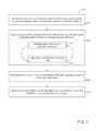
- FIG. 2shows a flow chart of navigating an autonomous robot.
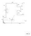
- FIG. 3shows a top view of an area with an autonomous robot.
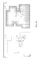
- FIGS. 4A-Cshow the room and the autonomous robot of FIG. 3 , different paths followed by the autonomous robot, and virtual maps corresponding to the room.
- An autonomous robotintelligently navigates about a room using simultaneous localization and mapping (SLAM) techniques.
- the robotcan localize by sensing natural features of the room.
- the robotcan use one or more visual sensors and one or more dead reckoning sensors to process data pertinent to SLAM and to autonomously generate and update a map.
- a controller of the robotoperates a sensor system to continuously estimate the pose of the robot within the room as the robot moves around and to receive information about the room.
- a “pose” hereinincludes a position of the robot within the room (e.g., an x, y coordinate location) and an angular orientation of the robot relative to, for example, a wall in the room or a cardinal direction.
- a sensed “feature” hereindescribes information and data collected from physical elements of the environment. For example, a feature can correspond to a geometric contour sensed by the robot as the robot navigates around physical elements of the environment.
- the robotIn some examples of intelligent navigation of the robot, the robot generates templates, or landmarks, corresponding to one or more features of the environment that the robot can detect using, e.g., sensors on the robot.
- the robotbuilds a map of a physical layout of the environment (e.g., one or more rooms or sections within a room), the physical layout including unique landmarks (herein also referred to as “signatures”) that include the one or more features.
- the robotestimates its pose within the environment and reduces the error in pose estimation using the generated templates.
- the robotcan generate the templates of path segments corresponding to a unique combination of features that identify a particular arrangement and location of obstacles and/or walls.
- the features stored in the templatesinclude a compilation of sensor data from the sensors that identifies each unique path segment.
- the sensor datacan include geometry (sensed by non-contact rangefinding sensors, e.g. volumetric point cloud sensors, IR point and line ranging sensors and sonar), bump sensor data, image data, and other data generated by sensors of the sensor system.
- the robotAs the robot moves about the room, the robot generates data indicative of a physical layout of the room that the controller uses to produce a virtual map or occupancy grid stored on a memory storage element. As the occupancy grid is generated, the controller tracks and continuously updates data indicative of the pose of the robot within the occupancy grid.
- the data indicative of the posecan be an estimate that increases in error as the robot continues to move about the room. In some examples, the robot represents the error as a measure of confidence associated with the estimated pose.
- the robotrepresents the error as a measure of uncertainty associated with the estimated pose.
- the robotcan decrease the uncertainty or increase the confidence in its pose estimation by moving the robot to a suspected location of one of the path segments described above.
- the sensor system of the robotcan generate signals corresponding to its movement around the suspected location of the path segment.
- the robotimplements a template matching algorithm to determine if the generated sensor data matches the template corresponding the path segment generated earlier. If the sensor data matches the template, the controller can re-orient the occupancy grid by confirming the pose of the robot or re-localizing the robot based on the position of the template within the room, and thus restore confidence in the pose estimation.
- robot 100includes a body 102 , a forward portion 104 , and a rearward portion 106 .
- the robot 100can move across a floor surface of a physical environment through various combinations of movements relative to three mutually perpendicular axes defined by the body 102 : a transverse axis X, a fore-aft axis Y, and a central vertical axis Z.
- a forward drive direction along the fore-aft axis Yis designated F (referred to hereinafter as “forward”)
- an aft drive direction along the fore-aft axis Yis designated A (referred to hereinafter as “rearward”).
- the transverse axis Xextends between a right side R and a left side L of the robot 100 substantially along an axis defined by center points of, referring briefly to FIG. 1B , wheel modules 108 a , 108 b .
- the robot 100has a round circumference.
- the forward portion 104generally has a rectangular cross section and the rearward portion 106 is generally rounded, having a semicircular cross section.
- Other geometric shapes of the robot body 102are contemplated, such as a Reuleaux triangle or constant width polygon.
- a user interface 110 disposed on a top portion of the body 102receives one or more user commands and/or displays a status of the robot 100 .
- One or more obstacle detection sensors 111 disposed on the forward portion 104evaluate the distance of obstacles to the robot 100 .
- the one or more sensorsare point ranging time of flight sensors, line ranging sensors or volumetric point cloud sensors.
- the one or more obstacle detection sensors 111are sonar sensors disposed on the forward portion 104 serve as transducers of ultrasonic signals to evaluate the distance of obstacles to the robot 100 .
- a wall following sensor 113 on the right side of the robot 100is an IR sensor that can determine when the robot 100 is following a wall.
- the left side L of the robot 100can also have a wall following sensor.
- the forward portion 104 of the body 102further carries a bumper 115 , which detects obstacles in a drive path of the robot 100 .
- a bottom surface 107 of the robot 100includes the wheel modules 108 a - b with motors 109 a - b that differentially drive wheels 110 a - b .
- the motors 109 a - bare coupled to rotary encoders 112 a - b .
- the bottom surface 107 of the robot 100further includes a cleaning head 120 with a front roller 122 a and a rear roller 122 b , a side brush 125 , a caster wheel 130 , clearance regulators 132 a - b , an optical mouse sensor 133 , an inertial measurement unit (IMU) 134 , and cliff sensors 135 a - 135 d.
- IMUinertial measurement unit
- the wheel modules 108 a and 108 blocated along the transverse axis X, propel the robot 100 across the floor surface during a cleaning routine.
- the motors 109 a - bdrive their respective wheels 110 a - b .
- the rotary encoders 112 a - bmeasure the position of the motor shaft of the motors 109 a - b .
- an odometry systemuses the rotary encoders 112 a - b to estimate the distance travelled by the robot 100 .
- the bumper 115 disposed on the forward portion 104 of the robot 100detects the contact and produces a signal in response to contacting the obstacles.
- the bumper 115is a solid state tactile sensing bumper that can detect physical or electrical characteristics upon contacting an obstacle.
- the bumper 115may encompass some or all of the sides and reward portion of the robot.
- the bumper 115may include a contact sensor membrane that senses applied force and the contact sensor membrane may be applied around some or all of the periphery of the robot 100 such that contact with physical structures of the environment are sensed in any direction of movement.
- the robot 100can use the location of contact along the contact sensor membrane of the bumper 115 to avoid an obstacle or perform WALL FOLLOWING behavior.
- the bumper 115includes a capacitive bumper sensor disposed along front and side surfaces of the bumper 115 .
- the capacitive bumper sensorcan be disposed upward along a top surface of the bumper 115 so that the capacitive bumper sensor can sense contact with surfaces from additional directions (e.g., from above the robot). Examples of bumpers are disclosed in U.S. patent application Ser. No. 14/277,270, titled “Compliant Solid-State Bumper for Robot,” incorporated by reference herein in its entirety.
- the bumper 115is a moveable member and includes one or more mechanical switches such that contact with obstacles in the environment triggers the bumper switches 117 L and 117 R.
- the bumper switch 117 Ris located on the right side R of the robot 100 .
- the bumper switch 117 Lis located on the left side L of the robot 100 .
- the two bumper switches 117 L and 117 Rare located forward of the wheels 110 a - b relative to the forward drive direction F.
- more than one of the bumper switches 117 L and 117 Rcan be triggered sequentially.
- the robot 100can use the sequential actuation of the bumper switches 117 R and 117 L to avoid an obstacle or perform WALL FOLLOWING behavior.
- the removable cleaning head 120is mounted on the forward portion of the chassis and includes two counter rotating rollers mounted therein, front roller 122 a and rear roller 122 b , for retrieving debris from a cleaning surface.
- the robot body 102includes a side brush 125 , or corner brush, disposed on the bottom forward portion 104 of the robot body 102 .
- the side brush 125sits on a lateral side of the forward portion 104 of the body 102 .
- the front roller 122 a and the rear roller 122 bcooperate with the side brush 125 to clean the floor of the region by ingesting debris redirected into the path of the front roller 122 a and rear roller by the 122 b by the side brush 125 which extends beyond the perimeter of the robot body 102 to ensnare debris in crevices and along edges beyond the reach of the cleaning head 120 .
- the caster wheel 130supports the rearward portion 106 of the robot body 102 such that the cantilevered cleaning head 120 is biased toward the cleaning surface.
- the caster wheel 130swivels and is vertically spring-loaded to bias the caster wheel 130 to maintain contact with the floor surface, and a sensor in the caster wheel 130 can detect if the robot 100 is no longer in contact with a floor surface (e.g. when the robot 100 backs up off a stair allowing the vertically spring-loaded swivel caster wheel 130 to drop).
- the clearance regulators 132 a - brotatably supported by the robot body 102 , maintain a minimum clearance height (e.g., at least 2 mm) between the bottom surface of the body 102 and the floor surface.
- the bottom of the robot body 102includes the optical mouse sensor 133 .
- the optical mouse sensorincludes a light source and a low-resolution camera.
- the light sourceilluminates the floor beneath the robot body 102 as the robot navigates about the environment, and the low-resolution camera continuously records and compares sequential low-resolution images (e.g., about 20 ⁇ 20 pixels) of the floor.
- the robot 100uses the optical mouse sensor 133 to estimate drift in the x and y directions as the robot 100 navigates about the environment.
- the robot body 102further houses an IMU 134 .
- the IMUincludes a 3-axis accelerometer and a 3-axis gyroscope.
- the 3-axis accelerometermeasures x, y, and z acceleration
- the 3-axis gyroscopemeasures rotation about the x-, y-, and z-axes (e.g., pitch, yaw, and roll).
- the accelerator of the IMU 134can be used to estimate drift in the x and y directions
- the gyroscope of the IMU 134can be used to estimate drift in the orientation ⁇ of the robot 100 .
- the robot 100includes multiple cliff sensors 135 a - d located near the forward and rear edges of the robot body 102 , behind the drive wheels 110 a - b at a distance that enables the robot 100 to receive a cliff sensor signal and have time to stop the wheels 110 a - b before moving off a sensed drop.
- Cliff sensors 135 b and 134 care located on the forward portion 104 near the front surface of the robot and cliff sensors 135 a and 135 d are located on a rearward portion 106 .
- Each cliff sensor 135 a - dis disposed near one of the side surfaces so that the robot 100 can detect an incoming drop or cliff from either side of its body 102 .
- Each cliff sensor 135 a - demits radiation, e.g. infrared light, and detects a reflection of the radiation to determine the distance from the cliff sensor 135 a - d to the surface below the cliff sensor 135 a - d .
- a distance larger than the expected clearance between the floor and the cliff sensor 135 a - de.g. greater than 2 mm, indicates that the cliff sensor 135 a - d has detected a cliff-like obstacle or environmental element in the floor topography.
- the hardware of the robot hereincan include aspects of the robotic system disclosed in application no. PCT/US2014/025665 filed on Mar. 13, 2014 and titled “Roller brush for surface cleaning robots” and U.S. application Ser. No. 13/460,261 filed on Apr. 30, 2012 and titled “Robotic Vacuum,” both of which are hereby incorporated by reference in its entirety.
- the body 102 of the robot 100houses a control system 149 that includes a power system 150 , a cleaning system 155 , a drive system 160 , a navigation system 170 , a sensor system 180 , a controller circuit 190 (herein also referred to as “controller 190 ”), and a memory storage element 195 .
- the power system 150which includes a power source, provides electric power to the systems operable with the robot 100 .
- the power system 150can further include a charging system within the power system 150 that is connectable to an external charging dock to charge the power source.
- the cleaning system 155uses rollers 122 a - b , the side brush 125 , and a debris bin fan 123 housed in the robot body 102 to ingest debris.
- the drive 160can maneuver the robot 100 across the floor surface based on a drive command having x, y, and ⁇ components (shown in FIG. 1A ).
- the drive 160controls motors 109 a , 109 b to drive wheels 110 a - b of the wheel modules 108 a - b such that the wheel modules 108 a - b can propel the robot 100 in any drive direction along the floor surface.
- the wheel modulescan be differentially operated such that the robot can turn based on a level of drive supplied to each drive wheel 110 a - b .
- Independent motors 109 a , 109 b of the wheel modules 108 a - bdrive each wheel 110 a - b such that the wheels 110 a - b can rotate independently from one another. As a result, independent rotation of the wheels 110 a - b can rotate the forward drive direction F of the robot 100 to a new heading.
- the navigation system 170a behavior-based system executed on the controller 190 , can send instructions to the drive system 160 so that the robot 100 can use the drive 160 to navigate an environment.
- the navigation system 170communicates with the sensor system 180 to issue drive commands to the drive 160 .
- the sensor system 180includes sensors disposed on the robot 100 , such as the obstacle detection sensors 111 , the wheel encoders 112 a - b , the bumper switches 117 L and 117 R, the optical mouse sensor 133 , the IMU 134 , and the cliff sensors 135 a - e .
- Some or all of the sensors of the sensor system 180generate data related to features of structural elements in the environment, thereby enabling the navigation system 170 determine a mode or behavior to use to navigate about the environment for complete coverage of a room or cell or for avoiding a potential hazard, such as a low overhang that would render a wedged condition or a lamp base that would render a beached condition.
- One or more of the various sensors of the sensor system 180can be used to generate data related to one or more features or landmarks.
- the sensor system 180creates a perception of the robot's environment sufficient to allow the robot 100 to make intelligent decisions about actions (e.g., navigation actions, drive actions) to take within the environment.
- the sensor system 180gathers the data to allow the robot 100 to implement SLAM techniques, as will be described later.
- the sensor system 180can include obstacle detection obstacle avoidance (ODOA) sensors, ranging sonar sensors, proximity sensors, radar sensors, LIDAR (Light Detection And Ranging, which can entail optical remote sensing that measures properties of scattered light to find range and/or other information of a distant target) sensors, clearance sensors operable with the clearance regulators 132 a - b , a camera (e.g., volumetric point cloud imaging, three-dimensional (3D) imaging or depth map sensors, visible light camera and/or infrared camera), wheel drop sensors operable with the caster wheel 130 that can detect movement of the caster wheel 130 .
- ODOAobstacle detection obstacle avoidance
- ranging sonar sensorsranging sonar sensors
- proximity sensorse.g., radar sensors
- LIDARLight Detection And Ranging
- LIDARLight Detection And Ranging
- clearance sensorsoperable with the clearance regulators 132 a - b
- a camerae.g., volumetric point cloud imaging, three-dimensional
- the sensor systemcan also include communication sensors, navigation sensors, contact sensors, a laser scanner, and other sensors to facilitate navigation, detection of obstacles, and other tasks of the robot 100 .
- the proximity sensorscan take the form of contact sensors (e.g. a sensor that detects an impact of a bumper on the robot with a physical barrier, such as a capacitive sensor or a mechanical switch sensor) and/or LIDAR sensors that detect when the robot is in close proximity to nearby objects.
- the controller 190operates the other systems of the robot 100 by communicating with each system, providing and receiving input and output parameters.
- the controller 190facilitates communication between the power system 150 , the cleaning system 155 , the drive system 160 , navigation system 170 , the sensor system 180 , and the memory storage element 195 .
- the controller 190can instruct the power system 150 to provide electrical power to the motors of the drive system 160 to move the robot 100 in the forward drive direction F.
- the controller 190can also instruct the power system 150 to enter a power charging mode.
- the controller 190can instruct the power system 150 to provide a specific level of power (e.g., a percent of full power) to individual systems.
- the controller 190can redirect the wheel modules 108 a - b of the drive system 160 in response to, for example, signals received from the navigation system 170 and the sensor system 180 .
- the controller 190operates the navigation system 170 to maneuver the robot 100 in a path or route through the environment.
- the navigation system 170can deliver instructions to the robot controller 190 to maneuver the robot 100 in any direction across the environment by independently controlling the rotational speed and direction of each wheel module 108 a - b of the drive system 160 .
- the robot controller 190can maneuver the robot 100 in the forward direction F, rearward direction A, right direction R, and left direction L.
- the robot controller 190can maneuver the robot 100 to rotate substantially in place such that the robot 100 can maneuver away from or along an obstacle, wall, or other structural element of the environment.
- the robot controller 190can direct the robot 100 over a substantially random (e.g., pseudo-random) path while traversing the floor surface or, in SLAM or VSLAM enabled robots, in a deterministic cleaning pattern.
- the robot 100can respond to events, such as contacting obstacles and walls within an area, detected by the bumper 115 .
- a responsecan include using the navigation system 170 and drive system 160 to control the wheel modules 108 a - b to maneuver the robot 100 in response to the event.
- the robot 100can, for example, move away from an obstacle or along a path adjacent to the obstacle.
- the controller 190can include obstacle detection and avoidance methods and behaviors implemented in response to actuation of the bumper switch 117 L and 117 R.
- the robotcan use the bumper switches 117 L and 117 R to detect the general location of an obstacle in the general vicinity of the robot 100 so that the robot 100 can determine the direction to turn to avoid the obstacle.
- the controller 190can determine when the robot contacts an obstacle and communicate instructions to the navigation system 170 and the drive system 160 to avoid the obstacle.
- the controller 190can further estimate an angle relative to the contact point between the robot 100 and the obstacle by calculating a time difference between the activation of the left and right bumper switches 117 L and 117 R, if both are activated. The robot is then able to estimate the angle at which contact was made.
- the bumper 115is contacted from the right side, the right bumper switch 117 R detects the bump first, followed by the left bumper switch 117 L, due to the compliance of the bumper 115 and the position of the bumper switches 117 R and 117 L. This way, the bump angle can be approximated with only the two bumper switches 117 R and 117 L.
- the robot 100can also use the wall following sensors 113 to estimate the angle that the robot 100 turns in order to move in a direction parallel to the obstacle.
- the wall following sensors 113are time-of-flight sensors that can identify a distance from an obstacle.
- the controller(which will be described in more detail below) can respond to the data of the wall following sensors such that either of the lateral sides L and R of the robot 100 are a set distance from the obstacle as the robot 100 moves in the forward direction F.
- the bumper 115has been shown to include the bumper switches 117 R and 117 L to collect information about contact with obstacles, in other implementations, it should be understood an alternative bumper can be used to contact obstacles and physical structures in the environment.
- a capacitive contact sensorcan be used to detect the contact point of the bumper 115 as the bumper 115 contacts a physical structure of the environment. Based on the contact, the robot 100 can re-orient to execute WALL FOLLOWING behavior, as will be described in more detail below.
- the memory storage element 195can include modules that acquire data related to SLAM.
- the memory storage element 195includes a pose module 198 a , a mapping module 198 b , and a signature module 198 c .
- Each modulecollects and stores data related to mapping the environment and localizing the robot 100 using detectable landmarks within the environment.
- the data generated by the modulesincludes data indicative of traveled unique path segments within the environment that are recognizable landmarks (e.g., unique landmarks for re-localization), data indicative of a physical layout of the environment (e.g., occupancy grid), and data indicative of a calculated robot pose (e.g., estimated pose).
- the datacan include odometry data from, for example, the encoders 112 a - b , the optical mouse sensor 133 , and the IMU 134 .
- the modulesfurther can include pre-programmed data such as pre-loaded maps and landmark templates.
- the control system 149allows the robot 100 to estimate its pose in the environment using the pose module 198 a .
- the controller 190 of the control system 149implements a dead reckoning process to estimate the pose of the robot 100 .
- the controller 190can use the encoders 112 a - b to track the distance traveled by the robot 100 .
- the controller 190can improve the accuracy of drift or wheel slippage associated with the dead reckoning data by incorporating an optical mouse sensor 133 and/or an IMU 134 .
- the optical mouse sensor 133estimates the drift in the x and y directions.
- the controller 190can utilize sensed linear acceleration from the 3-axis accelerometer of the IMU 134 to estimate the drift in the x and y directions as well and can utilize the 3-axis gyroscope of the IMU 134 to estimate the drift in the heading or orientation ⁇ of the robot 100 .
- the controller 190can therefore combine data collected by the rotary encoders 112 a - b , the IMU 134 , and the optical mouse sensor 133 to produce improved estimates of the pose of the robot 100 at a given time.
- the controller 190assigns an uncertainty value, a confidence value (inversely proportional to the uncertainty value), or an uncertainty covariance matrix, or some other value representative of the accumulated error for each pose that the controller 190 estimates using the pose module 198 a . For example, as the robot 100 travels a farther linear distance, the controller 190 assigns an increasing uncertainty to the estimated (x, y) position of the robot 100 , and as the robot 100 re-orients itself, the controller 190 assigns an increasing uncertainty to the estimated orientation ⁇ of the robot 100 . For each estimation of the pose, the estimation includes the position and orientation of the robot 100 as well as an uncertainty with the estimation. The robot 100 typically updates the estimation of its pose and the uncertainty in its estimation approximately every 10 milliseconds.
- the mapping module 198 ballows the controller 190 to generate a 2D grid of cells—an occupancy grid—to represent the physical layout of the environment.
- the occupancy grid generatedincludes data indicative of the physical layout of the area and represents both open areas and obstacles.
- the data indicative of the physical layout of the areacan be understood to a virtual map of the physical layout.
- the occupancy gridincludes a boundary of the environment and boundaries of obstacles therein, as well as the interior floor space traversed by the robot 100 .
- the controller 190determines and saves the grid coordinates of the robot 100 during its motion.
- the controller 190further associates an uncertainty value with each pose.
- Each cell in the occupancy gridcan be assigned a value indicating whether the cell is understood to be NON-TRAVERSABLE floor space and TRAVERSABLE floor space.
- Each cell of the gridcan be assigned (x, y) coordinates based on a chosen origin (0, 0) cell in the environment. The chosen origin can be, for example, the charging dock of the robot 100 or a particular location in the room.
- Each cellcan represent a square area with four sides. The sides of the cell coincide with the sides of other cells.
- the cellscan have a side length between 1 and 100 cm.
- the gridcan be a grid of cells, each 10 cm ⁇ 10 cm.
- the robot 100stores the (x, y) coordinates of each cell traversed by the robot 100 .
- the controller 190can mark all cells under the footprint of the robot 100 as TRAVERSABLE cells and mark all the cells corresponding to the wall being followed as NON-TRAVERSABLE. As will be described later, the controller 190 can recognize specific sequence, combinations, groups, etc. of cells that represent features and landmarks of the structural elements in the environment (e.g., walls, obstacles, etc.). In one implementation, before determining the value of cells in the grid, the controller 190 can pre-set the values of all cells to be UNKNOWN. Then, as the robot 100 drives during WALL FOLLOWING behavior, the values of all cells along its path are set to TRAVERSABLE, the location of the cells being determined by the distance to the origin.
- the controller 190can perform a flood fill to set the values of all cells inside the boundary made up of TRAVERSABLE cells as TRAVERSABLE cells that can be traversed.
- the mapping module 198 bcan update the map on a periodic basis, such as after travelling a threshold distance (e.g., once every meter or half meter travelled by the robot 100 ), after a threshold period of time (e.g., once every 1-3 seconds), or after collecting a threshold number of pose points (e.g., greater than 20 points).
- the confidence value of the posecould be derived from the VSLAM system or from the distance traversed or rotation amount of the robot or by the mismatch between information given by the odometry and the other sensors (e.g., optical mouse, gyroscope) or any combination of these.
- the mapping module 198 bfurther recognizes landmarks and features based on sensor data accumulated by the sensor system 180 .
- the mapping module 198 bhas been described to pre-set the cells in the grid to be UNKNOWN, in some cases, the mapping module 198 b can pre-set the cells to be NON-TRAVERSABLE or TRAVERSABLE and update the cells as the robot 100 discovers additional mapping data about the physical layout of the environment.
- the signature module 198 cstores data relating to the location of edges of obstacles and walls and stores templates of path segments traversed in the environment as unique signatures, or landmarks.
- the robot 100can receive data from its sensor system 180 that indicates a unique path segment constituting a landmark, which the signature module 198 c stores for future reference.
- Each unique signaturecan include the pose of the robot 100 at the start of navigating along the landmark.
- the unique signaturescan further include pose data collected as the robot 100 travels along the landmark.
- the unique signaturesare recognizable landmarks that the robot 100 uses re-localize within the occupancy grid and reduce the error in estimating robot pose.
- the robot 100stores the signature path segments, or landmarks, as the robot 100 follows obstacles and walls in the environment during WALL FOLLOWING behavior.
- WALL FOLLOWING behaviorconstitutes the robot following portions of surfaces of structural elements, thereby defining walls, furniture, or other obstacles in the environment on the occupancy map, and in other implementations, WALL FOLLOWING behavior constitutes following all peripheral edges of a room, tracing walls that bound the space.
- the WALL FOLLOWING behaviorimplements the pose module 198 a to store the estimated poses of the robot 100 as the robot 100 follows along surfaces within the environment.
- the robot 100can travel along a wall aligned with north-south, and the controller 190 can implement the signature module 198 c to assign a landmark corresponding to the poses indicative of the north-south wall.
- the robot 100can travel along an outside corner and store the landmark corresponding to the poses indicative of the outside corner.
- the robot 100can also derive the landmarks from inspecting the occupancy grid generated by the mapping module 198 b .
- the controller 190can perform a template matching algorithm on the occupancy grid to find physical landmarks and generate the unique signatures indicative of those landmarks.
- the signature module 198 ccan recognize three or more adjacent NON-TRAVERSABLE cells as a physical landmark to be stored in the signature module 198 c as a signature. If three cells form a line, the signature module 198 c can recognize the line of cells as a straight wall. The orientation of the line of cells can correspond to the orientation of the wall.
- the signature module 198 ccan label the line of cells as a unique signature corresponding to the wall.
- the signature module 198 ccan recognize three NON-TRAVERSABLE cells as a corner, where the two adjacent sides of one cell are each touching one of the other two cells. If each cell also touches a TRAVERSABLE cell, the signature module 198 c can label the three cells as a unique signature corresponding to an outside corner. If the sides of one of the cells do not touch a TRAVERSABLE cell, the signature module 198 c can label the three cells as a unique signature corresponding to an inside corner.
- the controller 190can generate a list of unique signatures that correspond to path segments within the environment, these path segments representing landmarks in the environment that the robot 100 has encountered during, for example, WALL FOLLOWING behavior or COVERAGE behavior.
- Other combinations of cells, including more or fewer cell groups,can indicate other features of the room, such as a curved wall or a sharp corner.
- FIG. 4Bwhich shows an example occupancy grid 400 a that has been partially populated
- white squaresrepresent TRAVERSABLE cells 421
- hashed squaresrepresent NON-TRAVERSABLE cells 422 .
- Cells classified as neither TRAVERSABLE nor NON-TRAVERSABLEare represented as blank space, though it should be understood that the blank space can include cells to represent the UNKNOWN cells 423 .
- three NON-TRAVERSABLE cells 422can be recognized as one of several unique signatures, e.g., an inside corner 426 a , an outside corner 426 b , an X-axis path 426 c , a Y-axis path 426 d .
- the three NON-TRAVERSABLE cells 422can be the inside corner 426 a .
- the cells marked by S 1correspond to the beginning of the path adjacent to the inside corners of the room 300 .
- the three NON-TRAVERSABLE cells 422can be an outside corner 426 b .
- the cells marked by S 2correspond to the beginning of the paths adjacent to the outside corners of the room 300 .
- the three NON-TRAVERSABLE cells 422can be the X-axis path 426 c .
- the cells marked by S 3correspond to the beginning of the paths adjacent to the landmarks of the room 300 that are parallel to the X-axis.
- the three NON-TRAVERSABLE cells 422can be the Y-axis path 426 d .
- the cells marked by S 4correspond to the beginning of the paths adjacent to the landmarks of the room 300 that are parallel to the Y-axis.
- the signatureshave been described to include three NON-TRAVERSABLE cells, in some implementations, the signatures can include fewer or more NON-TRAVERSABLE cells. In some cases, the signatures can include TRAVERSABLE cells. For example, a narrow path in the environment can be a TRAVERSABLE cell flanked by NON-TRAVERSABLE cells on either side of the TRAVERSABLE cell.
- the sensor data that the controller 190 associates with each unique signaturecan include database fields such as a signature ID, a landmark class, and a feature list.
- the signature ID fieldcan be a value used to uniquely identify the signature from among other signatures stored in the signature module 198 c.
- the landmark classis a classification value that classifies the landmark represented by the signature.
- landmark classescan include north-south wall, east-west wall, diagonal wall, inside corner, outside corner, rounded wall, protruding obstacle, and other curves and geometries that can be formed by obstacles and structural elements in the environment.
- these landmark classescan represent specific configurations of cells defined in the occupancy grid.
- the signature module 198 ccan be pre-loaded with a library of specific templates that are found in the environment.
- specific templatescan include templates representing sharp corners, inside corners, X-axis paths, and Y-axis paths.
- the library of templatescan include templates representing curved walls, narrow paths, acute angled walls, obtuse angled walls, and other geometries that can be found in the environment.
- the templates that are pre-loadedcan be user-uploaded or saved from a previous cleaning operation.
- the controller 190utilizes, for example, a template matching algorithm to search through the occupancy grid to find groups of cells that correspond to templates found in the library of templates.
- the controller 190assigns a signature ID to each group of cells found using the template matching algorithm and also assigns a landmark class to each signature ID based on the template in the library of templates used to identify the signature.
- the feature listcan include sensor data.
- the featurescan correspond to SIFT features.
- the robot 100uses the sensor system 180 , and in specific implementations, the bumper sensor, to observe the physical landmarks and generate a feature list corresponding to the sensor data associated with the walls, corners, obstacle surface contours, edges, curves and geometries that can be formed by obstacles and structural elements within the environment.
- the feature listcan include associations with the processed data from the pose module 198 a , timestamps from, for example, a computer's operating system time that can be used to store an indication of when the landmark was observed by the robot, and a timestamp of when the signature was added to the signature module 198 c .
- the controller 190can store the orientation ( ⁇ ) of the robot as part of the signature as the sensors collect data associated with the physical structural elements corresponding to the landmark.
- the initial estimate of the pose of a landmark that is referenced in the global reference framecan correspond to the pose of the robot 100 when the robot 100 begins to initiate WALL FOLLOWING behavior to follow the edges or surfaces of a structural element (e.g., wall), an obstacle (e.g., furniture), or a collection of or structural elements and obstacles.
- the feature list for a landmarkcan further include a length, distance, a number of cells, a position of cells, or other values that can represent the characteristics of the (x, y) coordinates of the cells of the landmark.
- the controller 190identifies multiple landmarks having the same landmark class, the feature list for the specific landmark can distinguish these landmarks from one another.
- the signatures for each landmark generated by and stored in the signature module 198 ccan be used to re-localize the robot 100 to reduce the uncertainty that the robot 100 has in poses estimated by the pose module 198 a.
- the electromechanical systems and modules disclosed and illustrated hereinmay include the systems and modules as disclosed in U.S. publication No. 20110167574, filed Nov. 5, 2010, titled “Methods and systems for complete coverage of a surface by an autonomous robot,” U.S. patent application Ser. No. 13/460,261, filed Apr. 30, 2012, titled “Robotic Vacuum,” U.S. patent application Ser. No. 11/688,213, filed Mar. 19, 2007, titled “Robot Confinement,” and U.S. Ser. No. 14/512,098 filed on Oct. 10, 2014 and titled “Robotic Lawn Mowing Boundary Determination,” the disclosures of which are incorporated by reference herein in their entireties.
- the memory storage element 195further includes behaviors for the robot 100 that cooperate with the modules 198 a - 198 c to perform SLAM techniques.
- the controller 190can execute behaviors that implement one of or combinations of the modules and use the data collected by the modules to map the environment and regularly re-localize the robot 100 to the map of the environment.
- the behaviorsinclude WALL FOLLOWING behavior, COVERAGE behavior, and RE-LOCALIZATION behavior.
- the robot 100detects a wall, obstacle (e.g., furniture, breakfast bar, cabinet toe kick, etc.), or other structure (e.g. fireplace hearth, stair edge, etc.) in the environment using the bumper 115 , follows the contours of the wall, obstacle or other structure, and then proceeds to generate a signature landmark using the signature module 198 c corresponding to the data collected as the robot 100 follows part or all of the structural element.
- the data collectedcan represent a feature or landmark from the pose module 198 a .
- the robot 100implements the wall following sensors 113 to perform the WALL FOLLOWING behavior.
- the robot 100can rotate until the robot 100 is oriented such that the forward drive direction F of the robot 100 is parallel with a surface of the obstacle.
- the wall, obstacle, or structural elementcan be curved such that the robot 100 follows a curved path as it move along the surface of the structural element.
- the robot 100can be oriented such that it is tangential to the surface of the structural element.
- the controller 190engages the pose module 198 a .
- the recorded sensor datawhich can include a feature (e.g., a geometric feature) of the structural element, is stored as part of the signature corresponding to the geometric contours of the structural element and thus becomes a landmark entry in the signature module 198 c database.
- the controller 190can implement WALL FOLLOWING behavior, where the robot 100 can make physical contact with an obstacle in the environment and re-orient the robot 100 such that the forward drive direction F of the robot 100 is parallel or tangential to the surface of the obstacle.
- the WALL FOLLOWING behaviorallows the robot 100 to follow a path corresponding to the edges of the obstacle.
- the controller 190can interpret the time difference between the actuation of the right and left bumper switches 117 L and 117 R to determine the contact angle.
- the contact angleprovides an estimate of the amount that the robot 100 needs to turn in order to align its forward drive direction F with the obstacle.
- the controller 190can instruct the robot 100 to turn a fraction of the required turning angle and then continue in the forward drive direction F.
- the controller 190can then estimate the contact angle and continue adjusting the orientation of the robot. Once the contact angle is below a certain amount, the controller 190 can instruct the robot to turn the full angle so that the forward drive direction F is parallel to the obstacle. The robot then proceeds to follow the wall in the WALL FOLLOWING behavior. In some implementations of the WALL FOLLOWING behavior, the controller 190 uses the wall following sensors to determine at what orientation to stop rotating the robot 100 . When the wall following sensors determine that the side of the robot 100 is substantially parallel to the obstacle, the controller 190 ceases rotation.
- the controller 190uses the wall following sensors to determine the orientation of the robot 100 that will cause the robot 100 to have a forward drive direction substantially tangential to the surface of the obstacle. In the case of curved surfaces, the controller 190 can use the tangential orientation to allow the robot 100 to follow along curve surface (e.g., cylindrical columns, curved walls, floor lamps, or other structural elements).
- curve surfacee.g., cylindrical columns, curved walls, floor lamps, or other structural elements.
- the robot 100can contact a second obstacle as the robot follows a first obstacle. For example, as the robot 100 follows a first wall in the forward drive direction F, the robot 100 can contact a second wall where the first wall meets the second wall at an inside a corner. Upon reaching that corner, the controller 190 re-orients the robot 100 (e.g. back up and turn 90 degrees) so that the robot 100 continues moving in the forward drive direction F along the second wall.
- the controller 190re-orients the robot 100 (e.g. back up and turn 90 degrees) so that the robot 100 continues moving in the forward drive direction F along the second wall.
- the controller 190can continuously execute the pose module 198 a , the mapping module 198 b , and the signature module 198 c .
- the mapping module 198 bcan populate the occupancy grid with TRAVERSABLE cells corresponding to the traversed area beneath the robot 100 and NON-TRAVERSABLE cells corresponding to the obstacle or obstacles that the robot 100 is following.
- the signature module 198 ccan further recognize unique path segments that the robot 100 has followed during WALL FOLLOWING that can be identified as a landmark.
- the controller 190can generate a signature corresponding to the sensed contours (e.g. number and placement of angles, number and placement of curves, and other measurable physical parameters (e.g. path length, path orientation, etc.) of the path, that signature being a recognizable landmark usable for re-localization of the robot 100 .
- the sensed contourse.g. number and placement of angles, number and placement of curves, and other measurable physical parameters (e.g. path length, path orientation, etc.) of the path, that signature being a recognizable landmark usable for re-localization of the robot 100 .
- COVERAGE behaviorinstructs the robot 100 to cover and clean the floor of the environment.
- the robot 100can cover the floor surface of the environment using coverage path techniques known in the art, such as a boustrophedon or cornrow pattern, a spiral pattern, or a pseudo-random bounce coverage.
- the controller 190can implement the pose module 198 a and the mapping module 198 b to estimate the pose of the robot 100 , generate the occupancy grid (e.g., the occupancy grids 400 a - 400 c of FIGS. 4A-4C , which will be described in detail later), and estimate the uncertainty of the pose estimations.
- the coverage patterncan be one in which the robot is navigated to cover the area in sequential passes in which each subsequent pass follows an edge of a region cleaned on a previous pass (e.g., as a spiral or a cornrow pattern), rather than a pseudo-random bounce pattern.
- the uncertainty of the controller 190may increase over time or distance travelled. If the uncertainty covariance computed by controller 190 increases to above a pre-determined threshold overall or individually in the x, y, or theta direction, the controller 190 can disable the mapping module 198 b that modifies and updates the occupancy grid.
- the pre-determined threshold for uncertaintycan be, for example, relative to the diameter of the robot in the x-y direction.
- the pre-determined thresholdmay be based on the standard deviation or covariance of the position of the robot.
- the pre-determined thresholdcan be computed based on the diameter of the robot.
- the thresholds of a covariance matrix of the uncertaintycan be set to a value relative to the diameter of the robot and the narrowest expected corridor or doorway in order to ensure the robot can properly navigate to any given landmark to re-localize.
- Exceeding the pre-determined thresholdcan cause the controller 190 to disable COVERAGE behavior and the mapping module 198 b .
- the occupancy grid of the mapping module 198 bcan become frozen in the last known-good state and remains that way until the robot 100 is able to reduce uncertainty in its pose, at which time the controller 190 may resume adding occupancy data to the mapping module 198 b .
- the robot 100will shift the occupancy grid, or portions thereof to align with reliably re-encountered landmarks.
- the controller 190can implement the RE-LOCALIZATION behavior to reduce the uncertainty of the pose estimate and to generally compute a correction for the pose of the robot 100 .
- the RE-LOCALIZATION behaviorcan be used by a SLAM process to correct for drift in the dead reckoning information.
- the controller 190Upon initializing the RE-LOCALIZATION behavior, the controller 190
- the controller 190can consider a number of factors to select a landmark to use for re-localization. For example, the controller 190 can compute the suspected distance—for example, the geodesic distance or the navigable distance—between the current estimated location of the robot 100 and the location of the nearest landmarks and select the landmark at the shortest distance. The controller 190 can consider the duration of time that has elapsed since the controller 190 has recorded each landmark and select the most recently recorded landmark. The controller 190 can further consider the uniqueness of each landmark compared to other landmarks and select the most unique of the landmarks. Uniqueness can be measured by the number of other landmarks having the same landmark class. The number of landmarks having the same landmark class is inversely proportional the uniqueness.
- the controller 190can compute an estimated distance to the landmark and an estimated angle of incidence with a geometric feature or contour of the landmark.
- the angle of incidencecan correspond to an expected angle of contact with the obstacle that includes the geometric feature or the landmark.
- the controller 190could also select a landmark depending on the relative uncertainty of the robot in a given direction—for example, if the uncertainty is above the threshold in the x direction the robot might select a landmark which will reduce the uncertainty in that direction, such as a wall that is orthogonal to the x direction.
- the robot controller 190can use a path planning algorithm known in the art—such as the A* algorithm or Dijkstra's algorithm—to direct the robot 100 to the suspected physical location of the landmark. These algorithms allow the robot 100 to avoid structure or walls that may intervene between the landmark the current position of the robot 100 .
- the controller 190can compute the contact angle based on an angle of contact with the bumper 115 as the bumper 115 contacts the structure represented by the landmark. Using the contact angle and the known contours of the landmark, the controller 190 can then compute the pose of the robot 100 . The controller 190 can compare this computed pose with the estimated pose of the robot 100 .
- the controller 190Based on the difference between the estimated pose and the computed pose, the controller 190 adjusts the estimated pose of the robot 100 to re-localize the robot 100 within the environment and relative to global occupancy grid coordinates. The discrepancy between the computed pose and the estimated pose can then be used to update the map with this new information. This could involve shifting the most recent parts of the occupancy grid or GraphSLAM map. Examples of updating the map are described in U.S. application Ser. No. 13/632,997 filed on Oct. 1, 2012 and titled “Adaptive mapping with spatial summaries of sensor data,” the content of which is hereby incorporated herein in its entirety.
- the robot 100can execute WALL FOLLOWING behavior to follow the geometric contours at the suspected physical location and to generate re-localization path data corresponding to these sensed contours.
- the robot 100compares the re-localization path data to the feature list of recorded landmarks and re-localize the robot 100 to the environment based on the difference between the re-localization path data and a landmark matching the identified geometric contours.
- the controller 190can proceed to WALL FOLLOWING behavior.
- the controller 190can further record the angle of contact when the bumper switches 117 L and 117 R are triggered.
- the robot 100proceeds to follow the surfaces or edges of the obstacle, wall or structure that triggered the bumper switches 117 L and 117 R and generates re-localization path data that can be used to determine if the obstacle, wall or structure corresponds to a landmark.
- the controller 190can begin generating the re-localization path after triggering the bumper sensor system 135 a first time. As the controller 190 proceeds through the path adjacent to the obstacle, triggering the bumper sensor system 135 a second time can indicate to the controller 190 to finish generating the re-localization path.
- the controllercan record the angle of contact for both the first and the second instances of triggering the bumper switches 117 R, 117 L.
- the controller 190after generating the re-localization path, can compare estimated values corresponding to the location of the landmark to actual values computed while the controller 190 generates the re-localization path.
- the controller 190can analyze the approach to and navigation along the structural element corresponding to the landmark. In analyzing the approach, the controller 190 can compare an estimated approach angle with a contact angle computed using the bumper sensor system (using, e.g., the bumper 115 ). For example, the controller 190 can estimate the approach angle based on the location of the landmark and the estimated current pose of the robot 100 . When the robot 100 contacts the landmark, the controller 190 can compute the angle of approach using the bumper sensors.
- the controller 190can compare these two angles and utilize these two angles to re-localize the orientation ⁇ of the robot 100 within the global coordinate system. During the approach, the controller 190 can further track the odometry and compare the odometry with an estimated distance to the structural element calculated using the estimated location of the robot 100 . The robot 100 can bump into the structural element represented by the feature earlier than expected. The controller 190 can use the differences between odometry and the estimated difference to re-localize the (x, y) position of the robot 100 .
- the robot 100can compare the poses estimated while generating the re-localization path to the poses stored in the landmark database.
- the difference between the posesincluding x, y, and ⁇ differences, can be used to re-localize each coordinate to the global coordinate system of the environment.
- the odometry along the re-localization pathcan be further compared to the odometry data associated with the landmark in the landmark database. If the a wall, obstacle or other structural element terminates at an intersection with another wall, obstacle or structural element, the contact angle between the robot with the subsequent obstacle can be compared with an angle associated with a landmark representing the intersection these two obstacles. For example, the robot 100 can select a landmark representing a first wall.
- the robot 100After generating the re-localization path along the first wall, the robot 100 contacts a second wall and can determine the contact angle using, for example, the bumper 115 . The robot then determines the difference between the contact angle and the angle between the first and second walls (as determined when the controller 190 implemented the signature module 198 c during WALL FOLLOWING behavior).
- the controller 190can compare the re-localization path with the landmark and determine that a percent match between the re-localization path and the landmark is below a pre-determined threshold. The percent match can consider both the approach to and the navigation along the path segment constituting the landmark. If the percent match is below the match threshold, the controller 190 can reinitialize the RE-LOCALIZATION behavior for another landmark.
- the match thresholdcan be based on the confidence threshold (or, in some examples, the uncertainty threshold) used for disabling the COVERAGE behavior and enabling the RE-LOCALIZATION behavior.
- the match threshold and the confidence thresholdcan be directly proportional such that a low confidence threshold results in a low match threshold and a high confidence threshold results in a high match threshold.
- the match thresholdcan be, for example, between 75% and 95%.
- the robot 100can initialize RE-LOCALIZATION behavior a second time for a second landmark known to be orthogonal to the first landmark.
- the first landmarkmay be aligned with the x- or y-axis. Such an alignment can result in a better re-localization for one of the two directions.
- the controllercan set one entry of the position to match the re-localization scheme. Repeating RE-LOCALIZATION behavior for a second signature orthogonal to the first landmark can allow the controller 190 to re-localize the robot 100 to better account for accumulated error or drift in the other coordinates, for example, x, y and ⁇ .
- the orthogonal signaturesprovide a 90° reference to re-localize the estimated orientation ⁇ of the robot 100 .
- Each signaturefurther provides a reference for re-localizing each of the estimated position coordinates x, y.
- the robot 100can select a landmark representing an outside corner or an inside corner.
- the controller 190can then choose to not repeat RE-LOCALIZATION behavior because the landmark can already be used to achieve the same restoration of pose confidence as using two orthogonal landmarks.
- the robotic behaviors disclosed and illustrated hereinmay include the routines and behaviors as disclosed in U.S. patent application Ser. No. 13/790,643, filed on Mar. 8, 2013, and titled “Simultaneous Localization and Mapping for a Mobile Robot,” which is herein incorporated by reference in its entirety.
- the pose estimation, wall following, and pose confidence computations of the disclosuremay also be alternatively implemented into the robotic systems of this application.
- the flow chart 200 of FIG. 2shows a method of navigating an autonomous robot 100 within an area at least partially enclosed by walls.
- the methodcan include aspects of the navigation, mapping, localization, and other SLAM-related software and hardware described above with respect to FIGS. 1A-C .
- step S 205the controller maneuvers the robot 100 in a following mode to control the robot to travel along a path segment adjacent an obstacle and record data indicative of the path segment.
- the controllercan execute the FOLLOWING behavior that utilizes the bumper sensor system to navigate the robot around obstacles and physical elements of the area.
- the FOLLOWING behaviorcan include execution of the pose module 198 a , the mapping module 198 b , and the signature module 198 c . As described earlier, these modules 198 a - c can cooperate to allow the robot 100 to record data indicative of the contours, length and/or directionality of the path segment adjacent the obstacle.
- step S 210the controller (e.g., the controller 190 of FIG. 1C ) maneuvers the robot 100 in a coverage mode to control the robot 100 to traverse the area while the robot 100 performs a function.
- the controlleralso generates data indicative of a physical layout of the area, including area boundaries and obstacle perimeters detected while the robot performs the function.
- the controllercan execute the COVERAGE behavior to maneuver the robot in the coverage mode.
- the robotas a result, can traverse the area using one of the coverage patterns described earlier in relation to the COVERAGE behavior.
- the function performed by the robotcan include a cleaning function executed by, for example, the cleaning system 155 of FIG. 1C .
- the controllercan instruct the robot to execute the pose module 198 a and the mapping module 198 b .
- the controllercan utilize the mapping module 198 b to generate the data indicative of the physical layout of the area, which can correspond to an occupancy grid stored on the memory storage element of the robot.
- the occupancy gridcan denote the area boundaries and obstacle perimeters using markers indicating TRAVERSABLE or NON-TRAVERSABLE, as described in relation to the mapping module 198 b.
- step S 215the controller updates data indicative of a current robot pose within the area.
- the current robot poseincludes a current location and orientation of the robot relative to global coordinates of the area.
- the controllerupdates the data indicative of the current robot pose based on at least on robot odometry data.
- the pose module 198 acan allow the controller to estimate the pose of the robot within the area.
- the controllercan update the data indicative of current robot location by comparing the data indicative of the path of the robot along the path segment to the data indicative of the path segment recorded in the following mode.
- the comparisoncan allow the robot to determine whether the path of the robot along the path segment sufficiently matches the path segment recorded in the following mode executed in the step S 205 .
- the controllerupon determining a sufficient match, can further update either of the data indicative of calculated robot location and the data indicative of the physical layout of the area, in accordance with the sufficiently matched path segment.
- the controllercalculates a robot pose confidence level.
- the confidence levelcan be computed based on estimated drift and error that may have accumulated during motion of the robot.
- the controllercontinues to perform the steps S 215 and S 220 until the robot pose confidence level falls below a predetermined confidence limit.
- step S 225in response to the robot pose confidence level being below a predetermined confidence limit, the controller maneuvers the robot to a suspected location of the path segment, based on the current robot pose.
- the controllercalculates the robot pose confidence level in the step S 220 , the controller can continuously compare the robot pose confidence level to the predetermined confidence limit.
- the controllercan execute the RE-LOCALIZATION behavior to re-localize the robot.
- the RE-LOCALIZATION behaviorcan instruct the robot to select a signature, which includes a location and orientation of the path segment that the controller can use to maneuver the robot to the suspected location of the path segment.
- the controllercan track the trajectory, the approach path, and, if the robot contacts an obstacle, the contact with the obstacle. After maneuvering the robot to the suspected location of the path segment, the controller can further maneuver the robot in the following mode to follow the path segment while the controller records robot pose data.
- the controllercan also record bumper sensor data. From the recorded robot pose data, the controller can generate data indicative of a path of the robot along the path segment.
- step S 230in response to detecting the suspected location of the path segment, the controller updates the data indicative of the calculated robot pose relative to the data indicative of the physical layout of the area. After re-localizing the robot 100 , the controller can direct the robot return to the position where its estimated pose confidence decreased to below the pre-determined confidence limit so that coverage resumes from that point.
- the methods, behaviors, and modules described abovecan be implemented for robotic devices in various situations and environments.
- the robot 100has been described to be a cleaning robot with a cleaning system, in other implementations, the robot can be a robotic lawnmower or other autonomous robot that estimates its own location and generates maps of the regions it navigates.
- FIGS. 3-4depicts the implementation of the robot and the control system as discussed with respect to FIGS. 1-2 .
- the robot 100navigates through a room 300 with walls 305 a - 1 and a bookshelf 310 .
- the global coordinate systemis defined by the X- and Y-axes.
- the walls 305 a , 305 c , 305 e , 305 g , 305 i , and 305 kare parallel to the X-axis, and the walls 305 b , 305 d , 305 f , 305 h , 305 j , and 305 l are parallel to the Y-axis.
- the bookshelf 310sits against the wall 305 j .
- the robot 100can estimate its pose within the global coordinate system, using the pose module 198 a as discussed with respect to FIG. 1C .
- the estimated poseincludes the position and the orientation of the robot 100 .
- the position of the robot 100 within the global coordinate systemis defined by x and y.
- the orientation of the robotis defined by ⁇ , as measured relative to the X-axis.
- FIG. 4Ashows the robot 100 in the room 300 of FIG. 3 as it executes WALL FOLLOWING behavior along the walls 305 a - 1 and a corresponding occupancy grid 400 a that the controller (e.g., the controller 190 of FIG. 1C ) of the robot 100 generates during WALL FOLLOWING behavior.
- a virtual robot 402is the virtual representation of the robot 100 within the occupancy grid 400 a .
- the center of the virtual robot 402represents the estimated (x, y) position of the robot 100 , and the line going from the center of the virtual robot 402 to the circumference represents the estimated orientation ⁇ of the virtual robot 402 .
- the robotfollows the path 410 a around the room 300 to mark the non-traversable boundaries of the room.
- the walls 305 a - 1 and the bookshelf 310define these boundaries.
- the controller of the robot 100implements the mapping module 198 b to generate the occupancy grid 400 a .
- the occupancy grid 400 aincludes hatch marked cells to represent NON-TRAVERSABLE cells and white cells to represent TRAVERSABLE cells.
- the controllerAs the robot 100 performs WALL FOLLOWING behavior, the controller generates cells marked by the symbols S 1 , S 2 , S 3 , or S 4 , in the occupancy grid 400 a of FIG. 4A .
- the cells marked by S 1correspond to the beginning of the path adjacent to the inside corners of the room 300 .
- the cells marked by S 2correspond to the beginning of the paths adjacent to the outside corners of the room 300 .
- the cells marked by S 3correspond to the beginning of the paths adjacent to the landmarks of the room 300 that are parallel to the X-axis.
- the cells marked by S 4correspond to the beginning of the paths adjacent to the landmarks of the room 300 that are parallel to the Y-axis.
- the robotmarks the non-traversable boundaries of the room by following the edge of an obstacle located away from the wall.
- an obstacle or stationary object located within the room but away from the wallmay be used as a landmark for re-localization.
- FIG. 4Bshows the robot 100 executing COVERAGE behavior.
- the robot 100follows the path 410 b .
- the controller of the robot 100implements the pose module 198 a and the mapping module 198 b to update the occupancy grid 400 b as the robot navigates about the room 300 .
- the controller of the robot 100further implements the pose module 198 a to compute the estimated pose of the robot 100 along the path 410 b and the confidence with the estimated poses.
- the confidencecan be computed as an average of the confidence of the robot 100 with each element of its pose.
- Points 415 a - c in the occupancy grid 400 brepresent estimations of the x, y location of the robot 100 as it navigates along the path 410 b .
- the points 415 a - conly represent a subset of the points generated along the path 410 b .
- the robot 100has a pose and pose confidence value (x, y, ⁇ , C, t), where x and y correspond to the estimated position of the robot 100 in the global coordinate system, ⁇ corresponds to the estimated orientation of the robot 100 relative to the global coordinate system, and C corresponds to the average confidence of the robot 100 .
- the points 415 a - calso can have a corresponding timestamp t that can be used to compute odometry.
- the point 415 ccorresponds to the end 419 of the path 410 b .
- the controller of the robot 100estimates the pose of the robot 100 , as represented by the virtual robot 402 in the occupancy grid 400 b .
- the position of the robot 100is estimated to be (2.1 m, 0.31 m).
- the controllerestimates the orientation of the robot to be 0° (zero degrees) relative to the X-axis.
- the actual position of the robot 100 within the room 300is (2.6 m, 0.29 m).
- the actual orientation of the robot 100is 8° relative to the X-axis. As shown in FIG.
- the confidence at the point 415 cis 89.7%, which is below the pre-determined confidence threshold, which, in this example, is 90%. Because of the pose confidence level falls below a threshold value, at the end 419 of the path 410 b , the robot 100 disengages COVERAGE behavior and proceeds to RE-LOCALIZATION behavior, as will be described with respect to FIG. 4C .
- FIG. 4Cshows the robot 100 executing RE-LOCALIZATION behavior to restore the confidence of the robot 100 in its estimated pose.
- the robot 100uses the pose module 198 a to estimate the current pose of the robot 100 as the controller (e.g., the controller 190 of FIG. 1C ) implements the RE-LOCALIZATION behavior.
- the controller of the robot 100can also disable the mapping module 198 b so that the controller does not continue to update the occupancy grid while the pose confidence is below the confidence threshold.
- the controller of the robot 100accesses the signature module 198 c to find a preferred landmark database entry corresponding to a landmark to which the controller can navigate the robot 100 .
- the robot 100is physically located at the location shown in the room 300 , and the controller of the robot 100 estimates the position of the robot 100 to be where the virtual robot 402 is shown in the occupancy grid 400 c .
- the virtual robot 402corresponds to the initial position of the virtual robot before starting RE-LOCALIZATION behavior.
- the controller of the robot 100estimates the five landmarks 420 a - e (labeled in FIG. 4B ) to be in closest proximity to the position of the virtual robot 402 .
- the controllerselects the landmark 420 c , which is physically manifested as an outside corner 425 in the room 300 .
- the controllergenerated the landmark 420 c during WALL FOLLOWING when the controller had a high confidence in its pose.
- a landmark path 430matches well with the physical path adjacent to the outside corner 425 .
- the landmark path 430 along the outside corner 425includes a start point 430 a , a turning point 430 b , and an end point 430 c.
- the controllercan estimate a suspected approach contact angle ⁇ s as the robot 100 approaches the wall 305 c .
- the controllerselects a trajectory 435 to move toward a suspected location of the start point 430 a of the landmark path 430 using a path planning algorithm as mentioned earlier.
- the controllerbases the trajectory 435 based on where it has estimated the start point 430 a to be and where it has estimated the virtual robot 402 to be.
- the robot 100moves along an actual trajectory 437 .
- the controllercan compute an actual approach contact angle ⁇ A . using the bumper sensor system of the robot 100 .
- the controllermarks the contact point with the wall 305 c as a start point 440 a of a re-localization path 440 .
- the robot 100turns to move along the wall 305 c toward the outside corner 425 .
- the controllerdetermines that the robot 100 has traversed the wall 305 c
- the robot 100turns to move parallel to the wall 305 d .
- the controllercan determine that the robot 100 has traversed the wall 305 c by, for example, using the bumper of the robot 100 as a tactile way of sensing that the wall 305 c is no longer adjacent to the wall 305 c .
- the robot 100can deliberately turn toward the wall 305 c to check that the wall 305 c is still adjacent.
- the controllermarks a turning point 440 b as the point at which the robot 100 turns to move along the wall 305 d .
- the controllerinstructs the robot to turn 90°.
- the controllerthen instructs the robot 100 to progress along the wall 305 d .
- a number of eventscan trigger the controller to direct the robot 100 to stop progressing along the wall 305 d .
- the controllercan stop progressing if the distance travelled as measured from the start point 440 a has exceeded the path length stored in the signature of the outside corner 425 .
- the controllermarks the stopping location with an end point 440 c that terminates the re-localization path 440 .
- the controllercan compare the parameters calculated from the re-localization path 440 with the parameters of the landmark path 430 .
- the controllercan compare assumed approach contact angle ⁇ s to the actual approach contact angle ⁇ A and can use the difference in the assumed approach contact angle ⁇ s and the actual approach contact angle ⁇ A to restore confidence in the estimation of the orientation of the robot 100 .
- the controllercan calculate (i) the distance between the start point 440 a and the turning point 440 b of the re-localization path 440 and (ii) the distance between the start point 430 a and the turning point 430 b of the signature path 430 .
- the controllercan compare these two distances and use the difference between the two distances to restore confidence in the estimation of the x position of the robot 100 .
- the controllercan calculate (i) the position difference between the start point 440 a of the re-localization path 440 and the start point 430 a of the signature path 430 or (ii) the position difference between the turning point 440 b of the re-localization path and the turning point 430 b of the signature path 430 .
- the controllercan use the difference between the two positions to restore confidence in the estimation of the y position of the robot 100 .
- the controllercan correct the pose (x, y, ⁇ ) of the virtual robot 402 and restore the confidence C.
- the virtual robots 450 a - b shown in FIG. 4Ccorrespond to the final positions of the virtual robot.
- a pre-localization final position 450 a of the virtual robot and a post-localization final position 450 bare shown in the occupancy grid 400 c .
- the post-localization final position 450 bbetter matches with the actual final position 460 of the robot 100 .
- the controllermay then update parts of the map to better match with the new corrected position.
- the full occupancy gridis comprised of many overlapping sub-grids, the relative position of these sub-grids may be updated.
- the controllermay update the position of the robot within a GraphSLAM pose constraint graph.
- GraphSLAM pose constraint graphSuch techniques are described in U.S. application Ser. No. 13/632,997 filed on Oct. 1, 2012 and titled “Adaptive mapping with spatial summaries of sensor data.”
- the controllercan then enable COVERAGE behavior and the mapping module 198 b .
- the controllercan re-direct the robot 100 to the position where it disabled the COVERAGE behavior, as shown in FIG. 4B .
- the robot 100can continue the cycle of COVERAGE behavior and RE-LOCALIZATION behavior until the controller has determined that the robot 100 has covered the room 300 .
- the robotcan further include other sensors known in the art to be beneficial for mobile robots.
- the bumper sensorcan advantageously include a pressure-based or capacitance based sensor, as disclosed in the U.S. patent application No. PCT/US2013/031264, filed on Mar. 14, 2013, and titled “Compliant Solid-State Bumper for Robot,” the contents of which are incorporated by reference in their entirety.
- the robotcan further include a camera to capture images of 3D features in the environment. The images can be used for VSLAM.
- the robotcan additionally or alternatively use specific wall following optical sensors. As the robot move along the wall, the wall following optical sensors determine that the robot moving along a path parallel to the wall.
- the robotcan use a spiral pattern.
- the robotcan use a combination of the patterns.
- the robotdecomposes an area into multiple regions and implements a different pattern in each region.
- the feature list of a signaturecan further include a “Last Observed Time” so that the robot can determine when the most recent signature was generated.
- the signaturecan also include a field that stores a timestamp that indicates the last time that the corresponding landmark information was updated.
- the signaturecan include a separate “Landmark Pose” field that stores a globally-referenced robot pose corresponding to when the landmark was created or updated to the database.
- the feature listcan further include information gathered by other sensors on the robot.
- the robotcan re-localize to a cliff or drop-off in the room.
- the signaturecan include cliff sensor data that distinguishes the cliff or drop-off from other structures in the room. While the obstacles of the room have been described to be wall or structural element, it should be understood that, if cliff sensor data is further incorporated into the SLAM system, the physical elements can include the absence of floor beneath the robot (e.g., a cliff), a change in floor characteristics (e.g., going from carpet to tile), or other features that the cliff sensors can detect.
- the SLAM systemcan discontinue adding new landmarks to the database in response to a predetermined number of entries, a predetermined density of entries, or a predetermined amount of time.
- the SLAM systemcan discontinue landmark creation in a portion of an environment or in the entire environment at least partly in response to a determination that the landmark density has exceeded a predetermined threshold, such as 5-10 landmarks per square meter.
- the addition of new landmarks to the databasecan be disabled for the portion of the environment corresponding to the relatively high landmark density in the database, and the addition of new landmarks can be enabled for portions of the environment corresponding to the relatively low landmark density.
- the controllerWhen the controller re-localizes the robot, the re-localization has been described to adjust the pose (x, y, and theta) once one or more signature matches occur.
- the cells of the occupancy grid or mapcan be adjusted such that they are rotated to align with the new localization scheme. For example, in a GraphSLAM-based map, the edges between cells can be adjusted based on the signature matches.”
- the occupancy gridhas been described to include TRAVERSABLE and NON-TRAVERSABLE cells.
- the occupancy gridcan further include BOUNDARY cells that represent cells between the TRAVERSABLE and NON-TRAVERSABLE areas. These cells can generally correspond to the cells covered during WALL FOLLOWING behavior.
- the templatecan include four or more cells.
- the templatescan include both TRAVERSABLE, NON-TRAVERSABLE, and—in the case that the occupancy grid uses BOUNDARY cells-BOUNDARY cells.
- controller 190has been described to consider a number of parameters in selecting a landmark for re-localization of the robot 100 , in some implementations, the controller arbitrarily picks a landmark from the signature module. In other implementations, the controller can consider other factors such as the confidence of the robot pose when the controller generated the landmark.
- the controllerinstructs the robot to seek out landmark.
- the robotmay decrease the confidence threshold and the match threshold to increase the likelihood that the controller finds a suitable match between a re-localization path and a localization path.
- the RE-LOCALIZATION behaviorcan direct the robot to the end point of the signatures.
- the controllercan re-compute expected poses along the path corresponding to the landmark path. For example, the controller may need to modify the expected orientation of the robot along the path.
- a confidencecan be assigned to each element of the estimated robot pose. For example, if the confidence of one of the elements decreases below the pre-determined confidence threshold, the robot can disable the mapping module and COVERAGE behavior and proceeds to RE-LOCALIZATION behavior. In other cases, the confidence is estimated from two of the elements.
- the robotmay be able to determine an altitude z.
- the environmentmay have altitude characteristics as well, and the robot can use these characteristics to re-localize the robot.
- the SLAM systems disclosed hereinmay include aspects of other SLAM systems known in the art.
- the algorithms and structures used in VSLAM system of the disclosure from U.S. application Ser. No. 10/739,902, filed on Dec. 17, 2003, and titled “Systems and methods for using multiple hypotheses in a visual simultaneous localization and mapping system”can be implemented into the SLAM systems described in this application. This disclosure is incorporated by reference in this application.
Landscapes
- Engineering & Computer Science (AREA)
- Radar, Positioning & Navigation (AREA)
- Aviation & Aerospace Engineering (AREA)
- Remote Sensing (AREA)
- Physics & Mathematics (AREA)
- General Physics & Mathematics (AREA)
- Automation & Control Theory (AREA)
- Robotics (AREA)
- Mechanical Engineering (AREA)
- Control Of Position, Course, Altitude, Or Attitude Of Moving Bodies (AREA)
Abstract
Description
- (i) selects a landmark found in the
signature module 198cto use for re-localization; - (ii) directs the
robot 100 to the suspected physical location of the landmark; - (iii) upon sensing a bumper sensor event consistent with the geometric contours of the landmark, adjusts the pose of the robot to re-localize the
robot 100 to the environment.
- (i) selects a landmark found in the
Claims (20)
Priority Applications (10)
| Application Number | Priority Date | Filing Date | Title |
|---|---|---|---|
| US14/661,633US9630319B2 (en) | 2015-03-18 | 2015-03-18 | Localization and mapping using physical features |
| CN202110170845.5ACN112947444B (en) | 2015-03-18 | 2015-07-10 | Localization and mapping using physical features |
| CN201510405861.2ACN106200633B (en) | 2015-03-18 | 2015-07-10 | Locating and mapping using physical features |
| CN201520500449.4UCN205247205U (en) | 2015-03-18 | 2015-07-10 | Autonomic robot |
| PCT/US2015/061079WO2016148743A1 (en) | 2015-03-18 | 2015-11-17 | Localization and mapping using physical features |
| EP20214136.2AEP3859477A1 (en) | 2015-03-18 | 2015-11-17 | Localization and mapping using physical features |
| EP15885756.5AEP3271784B1 (en) | 2015-03-18 | 2015-11-17 | Localization and mapping using physical features |
| US15/451,756US10500722B2 (en) | 2015-03-18 | 2017-03-07 | Localization and mapping using physical features |
| US16/707,383US11960304B2 (en) | 2015-03-18 | 2019-12-09 | Localization and mapping using physical features |
| US18/619,410US20240241522A1 (en) | 2015-03-18 | 2024-03-28 | Localization and mapping using physical features |
Applications Claiming Priority (1)
| Application Number | Priority Date | Filing Date | Title |
|---|---|---|---|
| US14/661,633US9630319B2 (en) | 2015-03-18 | 2015-03-18 | Localization and mapping using physical features |
Related Child Applications (1)
| Application Number | Title | Priority Date | Filing Date |
|---|---|---|---|
| US15/451,756ContinuationUS10500722B2 (en) | 2015-03-18 | 2017-03-07 | Localization and mapping using physical features |
Publications (2)
| Publication Number | Publication Date |
|---|---|
| US20160271795A1 US20160271795A1 (en) | 2016-09-22 |
| US9630319B2true US9630319B2 (en) | 2017-04-25 |
Family
ID=55946288
Family Applications (4)
| Application Number | Title | Priority Date | Filing Date |
|---|---|---|---|
| US14/661,633Active2035-07-02US9630319B2 (en) | 2015-03-18 | 2015-03-18 | Localization and mapping using physical features |
| US15/451,756Active2035-07-13US10500722B2 (en) | 2015-03-18 | 2017-03-07 | Localization and mapping using physical features |
| US16/707,383Active2036-06-27US11960304B2 (en) | 2015-03-18 | 2019-12-09 | Localization and mapping using physical features |
| US18/619,410PendingUS20240241522A1 (en) | 2015-03-18 | 2024-03-28 | Localization and mapping using physical features |
Family Applications After (3)
| Application Number | Title | Priority Date | Filing Date |
|---|---|---|---|
| US15/451,756Active2035-07-13US10500722B2 (en) | 2015-03-18 | 2017-03-07 | Localization and mapping using physical features |
| US16/707,383Active2036-06-27US11960304B2 (en) | 2015-03-18 | 2019-12-09 | Localization and mapping using physical features |
| US18/619,410PendingUS20240241522A1 (en) | 2015-03-18 | 2024-03-28 | Localization and mapping using physical features |
Country Status (4)
| Country | Link |
|---|---|
| US (4) | US9630319B2 (en) |
| EP (2) | EP3271784B1 (en) |
| CN (3) | CN112947444B (en) |
| WO (1) | WO2016148743A1 (en) |
Cited By (25)
| Publication number | Priority date | Publication date | Assignee | Title |
|---|---|---|---|---|
| US20180178822A1 (en)* | 2015-09-04 | 2018-06-28 | Gatekeeper Systems, Inc. | Estimating motion of wheeled carts |
| US10500722B2 (en) | 2015-03-18 | 2019-12-10 | Irobot Corporation | Localization and mapping using physical features |
| US20200167953A1 (en)* | 2017-07-28 | 2020-05-28 | Qualcomm Incorporated | Image Sensor Initialization in a Robotic Vehicle |
| US20200333800A1 (en)* | 2018-01-10 | 2020-10-22 | Sony Corporation | Animal-shaped autonomous mobile object, method of causing animal-shaped autonomous mobile object to perform motion, and program |
| US10831211B1 (en)* | 2018-06-11 | 2020-11-10 | United Services Automobile Association (Usaa) | Marker based navigation system for robotic vehicle |
| US11022976B2 (en)* | 2016-12-29 | 2021-06-01 | Amicro Semiconductor Corporation | Path planning method of intelligent robot |
| US11073842B1 (en)* | 2020-04-22 | 2021-07-27 | Boston Dynamics, Inc. | Perception and fitting for a stair tracker |
| US20210244246A1 (en)* | 2018-04-30 | 2021-08-12 | Lg Electronics Inc. | Vaccum cleaner and control method therefor |
| EP3808512A4 (en)* | 2018-06-15 | 2021-09-15 | Ecovacs Robotics Co., Ltd. | ROBOT LOCATION PROCEDURES, ROBOTS AND STORAGE MEDIUM |
| US20220080600A1 (en)* | 2020-09-15 | 2022-03-17 | Irobot Corporation | Particle filters and wifi robot localization and mapping |
| WO2022060530A1 (en) | 2020-09-15 | 2022-03-24 | Irobot Corporation | Robot localization and mapping accommodating non-unique landmarks |
| US20220107182A1 (en)* | 2019-01-28 | 2022-04-07 | Hardis Groupe | Locating method |
| US11414117B2 (en) | 2017-03-08 | 2022-08-16 | Gatekeeper Systems, Inc. | Anti-theft system that uses shopping cart location and vibration data |
| WO2023091804A1 (en) | 2021-11-22 | 2023-05-25 | Irobot Corporation | Trajectory-based localization and mapping |
| US11660752B2 (en) | 2019-04-12 | 2023-05-30 | Boston Dynamics, Inc. | Perception and fitting for a stair tracker |
| US11685049B2 (en) | 2020-04-22 | 2023-06-27 | Boston Dynamics, Inc. | Robot localization using variance sampling |
| US20240085190A1 (en)* | 2021-05-25 | 2024-03-14 | Qfeeltech (Beijing) Co., Ltd. | Map zone fusing method, apparatus, autonomous mobile device and storage medium |
| US12042926B2 (en)* | 2018-01-24 | 2024-07-23 | Qfeeltech (Beijing) Co., Ltd. | Cleaning robot |
| US12077229B2 (en) | 2020-04-22 | 2024-09-03 | Boston Dynamics, Inc. | Stair tracking for modeled and perceived terrain |
| US12094195B2 (en) | 2020-04-20 | 2024-09-17 | Boston Dynamics, Inc. | Identifying stairs from footfalls |
| US20250130572A1 (en)* | 2023-10-23 | 2025-04-24 | BrightAI Corporation | Systems and associated methods for multimodal feature detection of an environment |
| US12296694B2 (en) | 2021-03-10 | 2025-05-13 | Techtronic Cordless Gp | Lawnmowers |
| US12369509B2 (en) | 2022-07-19 | 2025-07-29 | Techtronic Cordless Gp | Display for controlling robotic tool |
| US12425197B2 (en) | 2022-07-29 | 2025-09-23 | Techtronic Cordless Gp | Generation of a cryptography key for a robotic garden tool |
| US12443180B2 (en) | 2022-11-09 | 2025-10-14 | Techtronic Cordless Gp | Robotic lawn mowers |
Families Citing this family (196)
| Publication number | Priority date | Publication date | Assignee | Title |
|---|---|---|---|---|
| US11835343B1 (en)* | 2004-08-06 | 2023-12-05 | AI Incorporated | Method for constructing a map while performing work |
| US9157757B1 (en)* | 2014-09-03 | 2015-10-13 | Sharp Laboratories Of America, Inc. | Methods and systems for mobile-agent navigation |
| US9969337B2 (en)* | 2014-09-03 | 2018-05-15 | Sharp Laboratories Of America, Inc. | Methods and systems for mobile-agent navigation |
| GB201419883D0 (en)* | 2014-11-07 | 2014-12-24 | F Robotics Acquisitions Ltd | Domestic robotic system and method |
| US9804594B2 (en)* | 2014-11-07 | 2017-10-31 | Clearpath Robotics, Inc. | Self-calibrating sensors and actuators for unmanned vehicles |
| US11685053B1 (en)* | 2014-11-24 | 2023-06-27 | AI Incorporated | Edge detection system |
| US10488865B2 (en)* | 2014-12-16 | 2019-11-26 | Al Incorporated | Methods and systems for robotic surface coverage |
| US20180361584A1 (en)* | 2015-01-06 | 2018-12-20 | Discovery Robotics | Robotic platform with long-term learning |
| KR101697857B1 (en)* | 2015-04-08 | 2017-01-18 | 엘지전자 주식회사 | Moving robot and method for recognizing a location of the same |
| US9918605B2 (en)* | 2015-04-09 | 2018-03-20 | Irobot Corporation | Wall following robot |
| US10180685B2 (en) | 2015-05-12 | 2019-01-15 | Viabot Inc. | Autonomous modular robot |
| US20170038772A1 (en)* | 2015-08-04 | 2017-02-09 | Gnetic Inc. | Modular Robot |
| GB2538779B (en) | 2015-05-28 | 2017-08-30 | Dyson Technology Ltd | A method of controlling a mobile robot |
| DE102015109775B3 (en) | 2015-06-18 | 2016-09-22 | RobArt GmbH | Optical triangulation sensor for distance measurement |
| DE102015114883A1 (en)* | 2015-09-04 | 2017-03-09 | RobArt GmbH | Identification and localization of a base station of an autonomous mobile robot |
| US10209063B2 (en)* | 2015-10-03 | 2019-02-19 | X Development Llc | Using sensor-based observations of agents in an environment to estimate the pose of an object in the environment and to estimate an uncertainty measure for the pose |
| DE102015119501A1 (en) | 2015-11-11 | 2017-05-11 | RobArt GmbH | Subdivision of maps for robot navigation |
| DE102015119865B4 (en) | 2015-11-17 | 2023-12-21 | RobArt GmbH | Robot-assisted processing of a surface using a robot |
| US10093021B2 (en)* | 2015-12-02 | 2018-10-09 | Qualcomm Incorporated | Simultaneous mapping and planning by a robot |
| DE102015121666B3 (en) | 2015-12-11 | 2017-05-24 | RobArt GmbH | Remote control of a mobile, autonomous robot |
| TW201727417A (en)* | 2016-01-26 | 2017-08-01 | 鴻海精密工業股份有限公司 | Analysis of the road curvature combined data recording system and method for analysing |
| EP3412136B1 (en) | 2016-02-03 | 2024-05-15 | Positec Power Tools (Suzhou) Co., Ltd | Self-moving device and control method therefor |
| DE102016102644A1 (en) | 2016-02-15 | 2017-08-17 | RobArt GmbH | Method for controlling an autonomous mobile robot |
| CN107305255A (en)* | 2016-04-25 | 2017-10-31 | 富士通株式会社 | Localization method, positioner and electronic equipment |
| DE102016212695B4 (en)* | 2016-05-31 | 2019-02-21 | Siemens Aktiengesellschaft | industrial robots |
| TWI614388B (en)* | 2016-06-02 | 2018-02-11 | 張韻詩 | Position pointer |
| CN107456173B (en)* | 2016-06-06 | 2020-12-04 | 北京小米移动软件有限公司 | Obstacle crossing method and device |
| JP7073336B2 (en) | 2016-08-05 | 2022-05-23 | ロブアート ゲーエムベーハー | How to control an autonomous mobile robot |
| DE102016215501B4 (en)* | 2016-08-18 | 2019-03-07 | Robert Bosch Gmbh | Landmark tag detection method and apparatus |
| CN106308685B (en)* | 2016-08-23 | 2019-10-11 | 北京小米移动软件有限公司 | cleaning robot and control method thereof |
| US9829333B1 (en)* | 2016-09-13 | 2017-11-28 | Amazon Technologies, Inc. | Robotic traffic density based guidance |
| CN106383517B (en)* | 2016-09-30 | 2019-06-07 | 汕头大学 | A kind of autonomous mobile robot platform control system, method and device |
| US10732127B2 (en)* | 2016-10-26 | 2020-08-04 | Pixart Imaging Inc. | Dirtiness level determining system and surface cleaning machine |
| US10274325B2 (en)* | 2016-11-01 | 2019-04-30 | Brain Corporation | Systems and methods for robotic mapping |
| US11042161B2 (en) | 2016-11-16 | 2021-06-22 | Symbol Technologies, Llc | Navigation control method and apparatus in a mobile automation system |
| DE102016125408A1 (en)* | 2016-12-22 | 2018-06-28 | RobArt GmbH | AUTONOMOUS MOBILE ROBOT AND METHOD FOR CONTROLLING AN AUTONOMOUS MOBILE ROBOT |
| CN108481320B (en)* | 2017-01-09 | 2020-03-27 | 广东宝乐机器人股份有限公司 | A kind of robot movement control method and robot |
| US10768682B2 (en)* | 2017-01-20 | 2020-09-08 | Flir Systems, Inc. | Detection-based wakeup of detection devices |
| TWI634403B (en)* | 2017-01-26 | 2018-09-01 | 好樣科技有限公司 | Automatic cleaning machine and control method thereof |
| CN106647774A (en)* | 2017-02-14 | 2017-05-10 | 南京罗普森智能科技有限公司 | Method for realizing autonomous exploration mapping and autonomous path covering of indoor robot cleaner |
| EP3974934A1 (en) | 2017-03-02 | 2022-03-30 | Robart GmbH | Method for controlling an autonomous mobile robot |
| KR101984101B1 (en)* | 2017-03-06 | 2019-05-30 | 엘지전자 주식회사 | Cleaner and controlling method thereof |
| US11656083B2 (en) | 2017-03-31 | 2023-05-23 | Intel Corporation | Autonomous tunnel navigation with a robotic system |
| US10963493B1 (en)* | 2017-04-06 | 2021-03-30 | AIBrain Corporation | Interactive game with robot system |
| US11151992B2 (en) | 2017-04-06 | 2021-10-19 | AIBrain Corporation | Context aware interactive robot |
| US10839017B2 (en) | 2017-04-06 | 2020-11-17 | AIBrain Corporation | Adaptive, interactive, and cognitive reasoner of an autonomous robotic system utilizing an advanced memory graph structure |
| US10929759B2 (en) | 2017-04-06 | 2021-02-23 | AIBrain Corporation | Intelligent robot software platform |
| US10810371B2 (en) | 2017-04-06 | 2020-10-20 | AIBrain Corporation | Adaptive, interactive, and cognitive reasoner of an autonomous robotic system |
| WO2018187943A1 (en)* | 2017-04-11 | 2018-10-18 | 珠海市一微半导体有限公司 | Method for creating grid map of intelligent robot |
| US10222215B2 (en)* | 2017-04-21 | 2019-03-05 | X Development Llc | Methods and systems for map generation and alignment |
| DE102017109219A1 (en) | 2017-04-28 | 2018-10-31 | RobArt GmbH | Method for robot navigation |
| US9939814B1 (en)* | 2017-05-01 | 2018-04-10 | Savioke, Inc. | Computer system and method for automated mapping by robots |
| CN110603533A (en) | 2017-05-01 | 2019-12-20 | 讯宝科技有限责任公司 | Method and apparatus for object state detection |
| US10949798B2 (en) | 2017-05-01 | 2021-03-16 | Symbol Technologies, Llc | Multimodal localization and mapping for a mobile automation apparatus |
| US11367092B2 (en) | 2017-05-01 | 2022-06-21 | Symbol Technologies, Llc | Method and apparatus for extracting and processing price text from an image set |
| WO2018204342A1 (en) | 2017-05-01 | 2018-11-08 | Symbol Technologies, Llc | Product status detection system |
| US11449059B2 (en) | 2017-05-01 | 2022-09-20 | Symbol Technologies, Llc | Obstacle detection for a mobile automation apparatus |
| WO2018201423A1 (en) | 2017-05-05 | 2018-11-08 | Symbol Technologies, Llc | Method and apparatus for detecting and interpreting price label text |
| US10882186B1 (en)* | 2017-05-11 | 2021-01-05 | AI Incorporated | Method for efficient operation of mobile robotic devices |
| DE102017111886B3 (en)* | 2017-05-31 | 2018-05-03 | Sick Ag | Determine the movement of a machine to be protected |
| US11009354B2 (en)* | 2017-07-06 | 2021-05-18 | Nuro Technologies, Inc. | Determining a layout in a living space |
| US10551843B2 (en)* | 2017-07-11 | 2020-02-04 | Neato Robotics, Inc. | Surface type detection for robotic cleaning device |
| US10353399B2 (en)* | 2017-07-21 | 2019-07-16 | AI Incorporated | Polymorphic path planning for robotic devices |
| JP7103585B2 (en)* | 2017-08-21 | 2022-07-20 | 日本電産シンポ株式会社 | Mobiles, mobile management systems and computer programs |
| DE102017120218A1 (en)* | 2017-09-01 | 2019-03-07 | RobArt GmbH | MOTION PLANNING FOR AUTONOMOUS MOBILE ROBOTS |
| US10012996B1 (en) | 2017-09-15 | 2018-07-03 | Savioke, Inc. | Route planning for a mobile robot using configuration-based preferences |
| DE102017008917A1 (en)* | 2017-09-22 | 2019-03-28 | Kuka Deutschland Gmbh | Method for locating a mobile robot |
| CN108852174B (en)* | 2017-09-25 | 2022-02-25 | 北京石头创新科技有限公司 | Autonomous mobile robot and pile searching method, control device and intelligent cleaning system thereof |
| US10422648B2 (en)* | 2017-10-17 | 2019-09-24 | AI Incorporated | Methods for finding the perimeter of a place using observed coordinates |
| US11274929B1 (en)* | 2017-10-17 | 2022-03-15 | AI Incorporated | Method for constructing a map while performing work |
| CN107680135B (en)* | 2017-11-16 | 2019-07-23 | 珊口(上海)智能科技有限公司 | Localization method, system and the robot being applicable in |
| CN107678440A (en)* | 2017-11-16 | 2018-02-09 | 苏州艾吉威机器人有限公司 | A kind of complementary locating formations, include its self-discipline mobile device and localization method |
| USD896858S1 (en)* | 2017-12-14 | 2020-09-22 | The Hi-Tech Robotic Systemz Ltd | Mobile robot |
| USD906390S1 (en)* | 2017-12-14 | 2020-12-29 | The Hi-Tech Robotic Systemz Ltd | Mobile robot |
| USD907084S1 (en)* | 2017-12-14 | 2021-01-05 | The Hi-Tech Robotic Systemz Ltd | Mobile robot |
| CN109960254B (en)* | 2017-12-25 | 2022-09-23 | 深圳市优必选科技有限公司 | Robot and path planning method thereof |
| USD879851S1 (en)* | 2017-12-29 | 2020-03-31 | Beijing Geekplus Technology Co., Ltd. | Robot |
| US10795377B2 (en)* | 2018-01-03 | 2020-10-06 | AI Incorporated | Method for autonomously controlling speed of components and functions of a robot |
| WO2019139243A1 (en)* | 2018-01-15 | 2019-07-18 | 에스케이텔레콤 주식회사 | Apparatus and method for updating high definition map for autonomous driving |
| CN108334080B (en)* | 2018-01-18 | 2021-01-05 | 大连理工大学 | Automatic virtual wall generation method for robot navigation |
| EP3534235B1 (en)* | 2018-02-28 | 2021-04-14 | Honda Research Institute Europe GmbH | Unsupervised learning of metric representations from slow features |
| USD879852S1 (en)* | 2018-03-15 | 2020-03-31 | Beijing Geekplus Technology Co., Ltd. | Mobile robot |
| US20210060780A1 (en)* | 2018-03-27 | 2021-03-04 | Zhongqian You | Robot avoidance control method and related device |
| US11256729B2 (en) | 2018-03-29 | 2022-02-22 | Aurora Operations, Inc. | Autonomous vehicle relative atlas incorporating hypergraph data structure |
| US10503760B2 (en) | 2018-03-29 | 2019-12-10 | Aurora Innovation, Inc. | Use of relative atlas in an autonomous vehicle |
| US10521913B2 (en) | 2018-03-29 | 2019-12-31 | Aurora Innovation, Inc. | Relative atlas for autonomous vehicle and generation thereof |
| US10823572B2 (en) | 2018-04-05 | 2020-11-03 | Symbol Technologies, Llc | Method, system and apparatus for generating navigational data |
| US11327504B2 (en) | 2018-04-05 | 2022-05-10 | Symbol Technologies, Llc | Method, system and apparatus for mobile automation apparatus localization |
| US10853561B2 (en)* | 2019-04-10 | 2020-12-01 | Fetch Robotics, Inc. | System and method for automatically annotating a map |
| US11427404B2 (en) | 2018-04-10 | 2022-08-30 | Fetch Robotics, Inc. | System and method for robot-assisted, cart-based workflows |
| US11454981B1 (en)* | 2018-04-20 | 2022-09-27 | AI Incorporated | Versatile mobile robotic device |
| CN110442123B (en)* | 2018-05-03 | 2022-08-05 | 南宁富联富桂精密工业有限公司 | Cleaning robot, cleaning method, environment monitoring method, and computer storage medium |
| US10751875B2 (en)* | 2018-05-31 | 2020-08-25 | Indoor Robotics Ltd | Rotatable mobile robot for mapping an area and a method for mapping the same |
| KR102047303B1 (en)* | 2018-06-01 | 2019-11-21 | 엘지전자 주식회사 | Robot of estimating direction based on vanishing point of low luminance image and method estimating thereof |
| CN108748148B (en)* | 2018-06-04 | 2021-03-16 | 常州信息职业技术学院 | Intelligent electrical control system for intelligent climbing robot and control method thereof |
| CA3106284A1 (en)* | 2018-08-08 | 2020-02-13 | The Toro Company | Handle and method for training an autonomous vehicle, and methods of storing same |
| USD911406S1 (en)* | 2018-08-17 | 2021-02-23 | Grey Orange Pte. Ltd | Robot for moving articles within a facility |
| DE102018121365A1 (en)* | 2018-08-31 | 2020-04-23 | RobArt GmbH | EXPLORATION OF A ROBOT APPLICATION AREA BY AN AUTONOMOUS MOBILE ROBOT |
| US11977378B2 (en)* | 2018-09-17 | 2024-05-07 | The Charles Machine Works, Inc. | Virtual path guidance system |
| CN110941258A (en)* | 2018-09-21 | 2020-03-31 | 日本电产株式会社 | Control method and control system for mobile body |
| CN110940994B (en)* | 2018-09-25 | 2024-06-18 | 北京京东乾石科技有限公司 | Positioning initialization method and system thereof |
| US11506483B2 (en) | 2018-10-05 | 2022-11-22 | Zebra Technologies Corporation | Method, system and apparatus for support structure depth determination |
| US11010920B2 (en) | 2018-10-05 | 2021-05-18 | Zebra Technologies Corporation | Method, system and apparatus for object detection in point clouds |
| US20230052887A1 (en)* | 2018-10-07 | 2023-02-16 | Erin Hong | Robotic Platforms and Robots for Nondestructive Testing Applications, Including Their Production and Use |
| US11747825B2 (en)* | 2018-10-12 | 2023-09-05 | Boston Dynamics, Inc. | Autonomous map traversal with waypoint matching |
| US12179737B2 (en)* | 2018-10-19 | 2024-12-31 | GEOSAT Aerospace & Technology | Unmanned ground vehicle and method for operating unmanned ground vehicle |
| CN113961005A (en) | 2018-10-22 | 2022-01-21 | 科沃斯机器人股份有限公司 | Travel control method, surface cleaning robot, and storage medium |
| US11080495B2 (en)* | 2018-10-25 | 2021-08-03 | Unified Information Devices, LLC | Animal motion and temperature monitoring |
| US11656626B2 (en) | 2018-11-12 | 2023-05-23 | Robotic Research Opco, Llc | Autonomous truck loading for mining and construction applications |
| US11644843B2 (en)* | 2018-11-12 | 2023-05-09 | Robotic Research Opco, Llc | Learning mechanism for autonomous trucks for mining and construction applications |
| US11353865B2 (en) | 2018-11-13 | 2022-06-07 | Robotic Research Opco, Llc | Coordination of mining and construction vehicles via scripting control |
| US11090811B2 (en) | 2018-11-13 | 2021-08-17 | Zebra Technologies Corporation | Method and apparatus for labeling of support structures |
| US11003188B2 (en) | 2018-11-13 | 2021-05-11 | Zebra Technologies Corporation | Method, system and apparatus for obstacle handling in navigational path generation |
| KR102327209B1 (en)* | 2018-11-20 | 2021-11-16 | 삼성전자주식회사 | Mobile apparatus and method for sensing the slope of the range sensor adhered to the mobile apparatus |
| CA3120728A1 (en)* | 2018-11-21 | 2020-05-28 | Ali Ebrahimi Afrouzi | Methods and systems for robotic surface coverage |
| CN109240312B (en)* | 2018-11-23 | 2020-09-15 | 珠海市一微半导体有限公司 | Cleaning control method and chip of robot and cleaning robot |
| US10611028B1 (en)* | 2018-11-30 | 2020-04-07 | NextVPU (Shanghai) Co., Ltd. | Map building and positioning of robot |
| US11416000B2 (en) | 2018-12-07 | 2022-08-16 | Zebra Technologies Corporation | Method and apparatus for navigational ray tracing |
| US11079240B2 (en)* | 2018-12-07 | 2021-08-03 | Zebra Technologies Corporation | Method, system and apparatus for adaptive particle filter localization |
| US11100303B2 (en) | 2018-12-10 | 2021-08-24 | Zebra Technologies Corporation | Method, system and apparatus for auxiliary label detection and association |
| US11015938B2 (en) | 2018-12-12 | 2021-05-25 | Zebra Technologies Corporation | Method, system and apparatus for navigational assistance |
| CA3028708A1 (en) | 2018-12-28 | 2020-06-28 | Zih Corp. | Method, system and apparatus for dynamic loop closure in mapping trajectories |
| CN109512344A (en)* | 2019-01-04 | 2019-03-26 | 云鲸智能科技(东莞)有限公司 | a mobile robot |
| GB201900859D0 (en)* | 2019-01-22 | 2019-03-13 | Gama Healthcare Ltd | Robotic, mobile apparatus for treating a room, for example by disinfection |
| CN111493743B (en) | 2019-01-31 | 2022-03-08 | 好样科技有限公司 | Cleaning machine and path planning method for cleaning machine |
| US11620478B2 (en)* | 2019-02-06 | 2023-04-04 | Texas Instruments Incorporated | Semantic occupancy grid management in ADAS/autonomous driving |
| JP7280719B2 (en)* | 2019-03-05 | 2023-05-24 | 東芝ライフスタイル株式会社 | autonomous vacuum cleaner |
| KR102243179B1 (en)* | 2019-03-27 | 2021-04-21 | 엘지전자 주식회사 | Moving robot and control method thereof |
| JP7231469B2 (en)* | 2019-04-19 | 2023-03-01 | 東芝ライフスタイル株式会社 | autonomous vacuum cleaner |
| WO2020219744A1 (en)* | 2019-04-24 | 2020-10-29 | Magic Leap, Inc. | Perimeter estimation from posed monocular video |
| EP3734391A1 (en)* | 2019-05-03 | 2020-11-04 | Terabee S.A.S. | Simultaneous localization and mapping |
| US11373318B1 (en) | 2019-05-14 | 2022-06-28 | Vulcan Inc. | Impact detection |
| US12040742B2 (en) | 2019-05-15 | 2024-07-16 | Xplor Llc | Scalable solar modular array |
| CN110225100B (en)* | 2019-05-22 | 2021-01-05 | 清华大学 | A virtual-real mapping system for intelligent assembly line |
| US11151743B2 (en) | 2019-06-03 | 2021-10-19 | Zebra Technologies Corporation | Method, system and apparatus for end of aisle detection |
| US11960286B2 (en) | 2019-06-03 | 2024-04-16 | Zebra Technologies Corporation | Method, system and apparatus for dynamic task sequencing |
| US11341663B2 (en) | 2019-06-03 | 2022-05-24 | Zebra Technologies Corporation | Method, system and apparatus for detecting support structure obstructions |
| US11402846B2 (en) | 2019-06-03 | 2022-08-02 | Zebra Technologies Corporation | Method, system and apparatus for mitigating data capture light leakage |
| US11080566B2 (en) | 2019-06-03 | 2021-08-03 | Zebra Technologies Corporation | Method, system and apparatus for gap detection in support structures with peg regions |
| US11200677B2 (en) | 2019-06-03 | 2021-12-14 | Zebra Technologies Corporation | Method, system and apparatus for shelf edge detection |
| US11662739B2 (en) | 2019-06-03 | 2023-05-30 | Zebra Technologies Corporation | Method, system and apparatus for adaptive ceiling-based localization |
| CN110347152B (en)* | 2019-06-11 | 2022-08-16 | 深圳拓邦股份有限公司 | Virtual wall setting method, system and device |
| KR102314537B1 (en)* | 2019-06-18 | 2021-10-18 | 엘지전자 주식회사 | Moving Robot and controlling method |
| KR102275300B1 (en)* | 2019-07-05 | 2021-07-08 | 엘지전자 주식회사 | Moving robot and control method thereof |
| KR102224637B1 (en)* | 2019-07-05 | 2021-03-08 | 엘지전자 주식회사 | Moving robot and control method thereof |
| KR102361130B1 (en)* | 2019-07-11 | 2022-02-09 | 엘지전자 주식회사 | Moving robot and control method thereof |
| KR102297496B1 (en) | 2019-07-11 | 2021-09-02 | 엘지전자 주식회사 | A ROBOT CLEANER Using artificial intelligence AND CONTROL METHOD THEREOF |
| KR102302575B1 (en) | 2019-07-16 | 2021-09-14 | 엘지전자 주식회사 | Moving robot and control method thereof |
| KR102224638B1 (en)* | 2019-07-31 | 2021-03-05 | 엘지전자 주식회사 | Moving Robot and controlling method |
| WO2021028672A1 (en)* | 2019-08-09 | 2021-02-18 | Quantum Leap Technologies Limited | Fabric maintenance system and method of use |
| CN110597249B (en)* | 2019-08-23 | 2022-08-05 | 深圳市优必选科技股份有限公司 | Robot and recharging positioning method and device thereof |
| KR20210028426A (en)* | 2019-09-04 | 2021-03-12 | 엘지전자 주식회사 | Robot Cleaner and Controlling method for the same |
| CN110874101B (en)* | 2019-11-29 | 2023-04-18 | 合肥哈工澳汀智能科技有限公司 | Method and device for generating cleaning path of robot |
| US11507103B2 (en) | 2019-12-04 | 2022-11-22 | Zebra Technologies Corporation | Method, system and apparatus for localization-based historical obstacle handling |
| US11107238B2 (en) | 2019-12-13 | 2021-08-31 | Zebra Technologies Corporation | Method, system and apparatus for detecting item facings |
| JP7547045B2 (en)* | 2019-12-19 | 2024-09-09 | キヤノン株式会社 | Information processing device, information processing method, and program |
| US11713977B2 (en)* | 2019-12-19 | 2023-08-01 | Canon Kabushiki Kaisha | Information processing apparatus, information processing method, and medium |
| CN110850885A (en)* | 2019-12-20 | 2020-02-28 | 深圳市杉川机器人有限公司 | Autonomous robot |
| CN113031509B (en)* | 2019-12-24 | 2022-07-29 | 苏州科瓴精密机械科技有限公司 | Traversal method, traversal system, robot and readable storage medium |
| CN110989635A (en)* | 2019-12-31 | 2020-04-10 | 浙江欣奕华智能科技有限公司 | Sweeping method of sweeping robot and sweeping robot |
| JP7441047B2 (en)* | 2020-01-10 | 2024-02-29 | 三菱重工業株式会社 | Route generation device, control device, inspection system, route generation method and program |
| CN111311775A (en)* | 2020-01-20 | 2020-06-19 | 深圳供电局有限公司 | Electric robot inspection system and method |
| US11822333B2 (en) | 2020-03-30 | 2023-11-21 | Zebra Technologies Corporation | Method, system and apparatus for data capture illumination control |
| CN111618856B (en)* | 2020-05-27 | 2021-11-05 | 山东交通学院 | Robot control method and system based on visual excitation points and robot |
| KR102423497B1 (en)* | 2020-07-02 | 2022-07-21 | 엘지전자 주식회사 | Controlling Method of Robot Cleaner |
| US11450024B2 (en) | 2020-07-17 | 2022-09-20 | Zebra Technologies Corporation | Mixed depth object detection |
| CN112045655B (en)* | 2020-08-14 | 2021-12-31 | 华中科技大学 | Mobile robot pose measurement method and system for large-scale multi-site scene |
| CN111941428B (en)* | 2020-08-17 | 2022-01-18 | 上海快仓智能科技有限公司 | Obstacle avoidance control method and device |
| CN112155476B (en) | 2020-09-16 | 2021-07-20 | 珠海格力电器股份有限公司 | A robot control method, device, electronic device and storage medium |
| US11593915B2 (en) | 2020-10-21 | 2023-02-28 | Zebra Technologies Corporation | Parallax-tolerant panoramic image generation |
| US11392891B2 (en) | 2020-11-03 | 2022-07-19 | Zebra Technologies Corporation | Item placement detection and optimization in material handling systems |
| US11847832B2 (en) | 2020-11-11 | 2023-12-19 | Zebra Technologies Corporation | Object classification for autonomous navigation systems |
| CN114610006B (en)* | 2020-11-24 | 2024-07-12 | 广东博智林机器人有限公司 | Working method and device of terrace equipment, terrace equipment and storage medium |
| CN112486172B (en)* | 2020-11-30 | 2024-08-02 | 深圳市普渡科技有限公司 | Road edge detection method and robot |
| KR20220078278A (en)* | 2020-12-03 | 2022-06-10 | 삼성전자주식회사 | Robot and method for generating map thereof |
| US11356801B1 (en)* | 2020-12-25 | 2022-06-07 | Mapsted Corp. | Method and system for targeted calibration |
| USD967883S1 (en)* | 2021-01-06 | 2022-10-25 | Grey Orange International Inc. | Robot for handling goods in a facility |
| JP2022121049A (en)* | 2021-02-08 | 2022-08-19 | トヨタ自動車株式会社 | Self-localization device |
| CN113108796B (en)* | 2021-04-19 | 2023-10-20 | 北京有竹居网络技术有限公司 | Navigation method, navigation device, storage medium and navigation equipment |
| CN113345018B (en)* | 2021-05-31 | 2022-06-14 | 湖南大学 | Laser monocular vision fusion positioning mapping method in dynamic scene |
| US11954882B2 (en) | 2021-06-17 | 2024-04-09 | Zebra Technologies Corporation | Feature-based georegistration for mobile computing devices |
| US12085942B1 (en)* | 2021-09-28 | 2024-09-10 | Google Llc | Preventing regressions in navigation determinations using logged trajectories |
| CN113854892B (en)* | 2021-10-21 | 2022-08-02 | 唐山学院 | A cleaning device that automatically plans a path |
| GB2613620B (en)* | 2021-12-10 | 2025-01-29 | Dyson Technology Ltd | Method for edge cleaning |
| US12094052B1 (en)* | 2022-01-19 | 2024-09-17 | Corelogic Solutions, Llc | Residential robotic device-based living area estimation |
| WO2023168707A1 (en) | 2022-03-11 | 2023-09-14 | Intelligent Cleaning Equipment Holdings Co. Ltd. | Systems and methods for tracking and scoring cleaning |
| US12260566B2 (en)* | 2022-04-07 | 2025-03-25 | Htc Corporation | Method for managing tracking devices, device manager, and computer readable storage medium |
| CN116945148B (en)* | 2022-04-15 | 2025-09-09 | 追觅创新科技(苏州)有限公司 | Robot control method, device, robot and storage medium |
| SE2250834A1 (en)* | 2022-07-04 | 2024-01-05 | Husqvarna Ab | Improved determination of pose for a robotic work tool |
| US20240036578A1 (en)* | 2022-07-26 | 2024-02-01 | Zebra Technologies Corporation | Generation of Navigational Paths Using Recursive Partitioning of Unoccupied Space |
| CN115016511A (en)* | 2022-08-08 | 2022-09-06 | 北京安录国际技术有限公司 | Robot control method and system based on artificial intelligence |
| CN115453524A (en)* | 2022-09-14 | 2022-12-09 | 山东科发建设工程有限公司 | Full-automatic radar ground hollowing detection device and detection method |
| CN115500737B (en)* | 2022-09-28 | 2023-10-17 | 云鲸智能(深圳)有限公司 | Ground medium detection method and device and cleaning equipment |
| CN117415811B (en)* | 2023-11-01 | 2025-01-10 | 天合光能股份有限公司 | Photovoltaic suspension type cleaning robot pose adjusting method and device and electronic equipment |
| CN118171574B (en)* | 2024-03-20 | 2024-11-01 | 北京科技大学 | Multi-agent coverage method based on lightweight A-algorithm under complex environment |
| CN118680465B (en)* | 2024-08-27 | 2024-11-26 | 卧安科技(深圳)有限公司 | Repositioning method of cleaning robot and cleaning robot |
Citations (40)
| Publication number | Priority date | Publication date | Assignee | Title |
|---|---|---|---|---|
| US20020016649A1 (en) | 2000-01-24 | 2002-02-07 | Jones Joseph L. | Robot obstacle detection system |
| US6389329B1 (en) | 1997-11-27 | 2002-05-14 | Andre Colens | Mobile robots and their control system |
| US20020120364A1 (en) | 1997-11-27 | 2002-08-29 | Andre Colens | Mobile robots and their control system |
| US20030025472A1 (en) | 2001-06-12 | 2003-02-06 | Jones Joseph L. | Method and system for multi-mode coverage for an autonomous robot |
| US20040020000A1 (en) | 2000-01-24 | 2004-02-05 | Jones Joseph L. | Robot obstacle detection system |
| US6690134B1 (en) | 2001-01-24 | 2004-02-10 | Irobot Corporation | Method and system for robot localization and confinement |
| US20040049877A1 (en) | 2002-01-03 | 2004-03-18 | Jones Joseph L. | Autonomous floor-cleaning robot |
| US20040187457A1 (en) | 2001-05-28 | 2004-09-30 | Andre Colens | Robotic lawnmower |
| US20040220707A1 (en) | 2003-05-02 | 2004-11-04 | Kim Pallister | Method, apparatus and system for remote navigation of robotic devices |
| US20050085947A1 (en)* | 2001-11-03 | 2005-04-21 | Aldred Michael D. | Autonomouse machine |
| US20050204717A1 (en) | 1999-06-17 | 2005-09-22 | Andre Colens | Device for automatically picking up objects |
| US20050234679A1 (en) | 2004-02-13 | 2005-10-20 | Evolution Robotics, Inc. | Sequential selective integration of sensor data |
| US7135992B2 (en) | 2002-12-17 | 2006-11-14 | Evolution Robotics, Inc. | Systems and methods for using multiple hypotheses in a visual simultaneous localization and mapping system |
| US7211980B1 (en)* | 2006-07-05 | 2007-05-01 | Battelle Energy Alliance, Llc | Robotic follow system and method |
| US20070266508A1 (en) | 2002-01-03 | 2007-11-22 | Irobot Corporation | Autonomous Floor Cleaning Robot |
| US20080140255A1 (en) | 2005-02-18 | 2008-06-12 | Irobot Corporation | Autonomous surface cleaning robot for wet and dry cleaning |
| US7388343B2 (en) | 2001-06-12 | 2008-06-17 | Irobot Corporation | Method and system for multi-mode coverage for an autonomous robot |
| US7389156B2 (en) | 2005-02-18 | 2008-06-17 | Irobot Corporation | Autonomous surface cleaning robot for wet and dry cleaning |
| US20110167574A1 (en) | 2009-11-06 | 2011-07-14 | Evolution Robotics, Inc. | Methods and systems for complete coverage of a surface by an autonomous robot |
| US20110202175A1 (en)* | 2008-04-24 | 2011-08-18 | Nikolai Romanov | Mobile robot for cleaning |
| US20110279652A1 (en) | 2010-05-14 | 2011-11-17 | Honda Research Institute Europe Gmbh | Two-stage correlation method for correspondence search |
| US20120121161A1 (en) | 2010-09-24 | 2012-05-17 | Evolution Robotics, Inc. | Systems and methods for vslam optimization |
| US8301374B2 (en) | 2009-08-25 | 2012-10-30 | Southwest Research Institute | Position estimation for ground vehicle navigation based on landmark identification/yaw rate and perception of landmarks |
| US20130138247A1 (en) | 2005-03-25 | 2013-05-30 | Jens-Steffen Gutmann | Re-localization of a robot for slam |
| US20130204465A1 (en) | 2006-07-14 | 2013-08-08 | Irobot Corporation | Autonomous Behaviors For A Remote Vehicle |
| WO2013138574A2 (en) | 2012-03-15 | 2013-09-19 | Irobot Corporation | Compliant solid-state bumper for robot |
| US20130244688A1 (en) | 2011-11-11 | 2013-09-19 | The Board of Trustees of the Leland Stanford, Junior, University | Method and System for Signal-based Localization |
| US20140032033A1 (en) | 2012-07-27 | 2014-01-30 | Honda Research Institute Europe Gmbh | Trainable autonomous lawn mower |
| WO2014047465A2 (en) | 2012-09-21 | 2014-03-27 | The Schepens Eye Research Institute, Inc. | Collision prediction |
| US8781630B2 (en) | 2008-10-14 | 2014-07-15 | University Of Florida Research Foundation, Inc. | Imaging platform to provide integrated navigation capabilities for surgical guidance |
| US8788205B2 (en) | 2012-12-17 | 2014-07-22 | Microsoft Corporation | Sensor data collection |
| US8798840B2 (en) | 2011-09-30 | 2014-08-05 | Irobot Corporation | Adaptive mapping with spatial summaries of sensor data |
| US20140277691A1 (en) | 2013-03-15 | 2014-09-18 | Cybernet Systems Corporation | Automated warehousing using robotic forklifts |
| WO2014151408A1 (en) | 2013-03-15 | 2014-09-25 | Irobot Corporation | Roller brush for surface cleaning robots |
| US8868237B2 (en) | 2006-03-17 | 2014-10-21 | Irobot Corporation | Robot confinement |
| US8881339B2 (en) | 2011-04-29 | 2014-11-11 | Irobot Corporation | Robotic vacuum |
| US20140368664A1 (en) | 2012-01-17 | 2014-12-18 | Aselsan Elektronik Sanayi Ve Ticaret Anonim Sirketi | System and method for measuring tracker system accuracy |
| US20140379296A1 (en) | 2013-06-22 | 2014-12-25 | Intellivision Technologies Corp. | Method of tracking moveable objects by combining data obtained from multiple sensor types |
| US20150046018A1 (en) | 2013-08-09 | 2015-02-12 | Toyota Jidosha Kabushiki Kaisha | Autonomous moving body, obstacle sensing method, and obstacle avoiding method |
| US9020637B2 (en) | 2012-11-02 | 2015-04-28 | Irobot Corporation | Simultaneous localization and mapping for a mobile robot |
Family Cites Families (24)
| Publication number | Priority date | Publication date | Assignee | Title |
|---|---|---|---|---|
| WO1995035531A1 (en)* | 1994-06-22 | 1995-12-28 | Siemens Aktiengesellschaft | Process for the orientation, route planning and control of a self-contained mobile unit |
| IL113913A (en)* | 1995-05-30 | 2000-02-29 | Friendly Machines Ltd | Navigation method and system |
| US5995884A (en)* | 1997-03-07 | 1999-11-30 | Allen; Timothy P. | Computer peripheral floor cleaning system and navigation method |
| US6046565A (en)* | 1998-06-19 | 2000-04-04 | Thorne; Henry F. | Robotic vehicle with deduced reckoning positioning system |
| US8396592B2 (en)* | 2001-06-12 | 2013-03-12 | Irobot Corporation | Method and system for multi-mode coverage for an autonomous robot |
| GB0126499D0 (en)* | 2001-11-03 | 2002-01-02 | Dyson Ltd | An autonomous machine |
| EP1587725B1 (en)* | 2002-08-30 | 2013-12-25 | Aethon, Inc. | Robotic cart pulling vehicle |
| JP2004275468A (en)* | 2003-03-17 | 2004-10-07 | Hitachi Home & Life Solutions Inc | Self-propelled vacuum cleaner and operating method thereof |
| US7689321B2 (en)* | 2004-02-13 | 2010-03-30 | Evolution Robotics, Inc. | Robust sensor fusion for mapping and localization in a simultaneous localization and mapping (SLAM) system |
| US20140012787A1 (en)* | 2009-12-18 | 2014-01-09 | Qin Zhang | System and method for information processing and motor control |
| KR100843085B1 (en)* | 2006-06-20 | 2008-07-02 | 삼성전자주식회사 | Grid map preparation method and device of mobile robot and method and device for area separation |
| EP2219506B1 (en)* | 2007-10-30 | 2017-06-21 | LG Electronics Inc. | Detecting apparatus of robot cleaner and controlling method of robot cleaner |
| KR101503903B1 (en)* | 2008-09-16 | 2015-03-19 | 삼성전자 주식회사 | Apparatus and method for building map used in mobile robot |
| KR101641237B1 (en)* | 2009-11-20 | 2016-07-21 | 엘지전자 주식회사 | Robot cleaner and controlling method of the same |
| CN102138769B (en)* | 2010-01-28 | 2014-12-24 | 深圳先进技术研究院 | Cleaning robot and cleaning method thereby |
| DE112011104645T5 (en)* | 2010-12-30 | 2013-10-10 | Irobot Corp. | Mobile human interface robot |
| EP2659323B1 (en)* | 2010-12-30 | 2018-06-13 | iRobot Corporation | Coverage robot navigation |
| KR101566207B1 (en)* | 2011-06-28 | 2015-11-13 | 삼성전자 주식회사 | Robot cleaner and control method thereof |
| CN103914068A (en)* | 2013-01-07 | 2014-07-09 | 中国人民解放军第二炮兵工程大学 | Service robot autonomous navigation method based on raster maps |
| JP6136543B2 (en)* | 2013-05-01 | 2017-05-31 | 村田機械株式会社 | Autonomous mobile |
| CN103271699B (en)* | 2013-05-29 | 2016-05-18 | 东北师范大学 | A kind of Smart Home clean robot |
| CN103472823B (en)* | 2013-08-20 | 2015-11-18 | 苏州两江科技有限公司 | A kind of grating map creating method of intelligent robot |
| CN104035444B (en)* | 2014-06-27 | 2016-08-24 | 东南大学 | Robot map structuring storage method |
| US9630319B2 (en) | 2015-03-18 | 2017-04-25 | Irobot Corporation | Localization and mapping using physical features |
- 2015
- 2015-03-18USUS14/661,633patent/US9630319B2/enactiveActive
- 2015-07-10CNCN202110170845.5Apatent/CN112947444B/enactiveActive
- 2015-07-10CNCN201510405861.2Apatent/CN106200633B/enactiveActive
- 2015-07-10CNCN201520500449.4Upatent/CN205247205U/ennot_activeExpired - Lifetime
- 2015-11-17WOPCT/US2015/061079patent/WO2016148743A1/ennot_activeCeased
- 2015-11-17EPEP15885756.5Apatent/EP3271784B1/enactiveActive
- 2015-11-17EPEP20214136.2Apatent/EP3859477A1/enactivePending
- 2017
- 2017-03-07USUS15/451,756patent/US10500722B2/enactiveActive
- 2019
- 2019-12-09USUS16/707,383patent/US11960304B2/enactiveActive
- 2024
- 2024-03-28USUS18/619,410patent/US20240241522A1/enactivePending
Patent Citations (62)
| Publication number | Priority date | Publication date | Assignee | Title |
|---|---|---|---|---|
| US6532404B2 (en) | 1997-11-27 | 2003-03-11 | Colens Andre | Mobile robots and their control system |
| US6389329B1 (en) | 1997-11-27 | 2002-05-14 | Andre Colens | Mobile robots and their control system |
| US20020120364A1 (en) | 1997-11-27 | 2002-08-29 | Andre Colens | Mobile robots and their control system |
| US20050204717A1 (en) | 1999-06-17 | 2005-09-22 | Andre Colens | Device for automatically picking up objects |
| US20040020000A1 (en) | 2000-01-24 | 2004-02-05 | Jones Joseph L. | Robot obstacle detection system |
| US6594844B2 (en) | 2000-01-24 | 2003-07-22 | Irobot Corporation | Robot obstacle detection system |
| US20020016649A1 (en) | 2000-01-24 | 2002-02-07 | Jones Joseph L. | Robot obstacle detection system |
| US7155308B2 (en) | 2000-01-24 | 2006-12-26 | Irobot Corporation | Robot obstacle detection system |
| US6690134B1 (en) | 2001-01-24 | 2004-02-10 | Irobot Corporation | Method and system for robot localization and confinement |
| US7196487B2 (en) | 2001-01-24 | 2007-03-27 | Irobot Corporation | Method and system for robot localization and confinement |
| US6781338B2 (en) | 2001-01-24 | 2004-08-24 | Irobot Corporation | Method and system for robot localization and confinement |
| US6965209B2 (en) | 2001-01-24 | 2005-11-15 | Irobot Corporation | Method and system for robot localization and confinement |
| US20050067994A1 (en) | 2001-01-24 | 2005-03-31 | Jones Joseph L. | Method and system for robot localization and confinement |
| US20040187457A1 (en) | 2001-05-28 | 2004-09-30 | Andre Colens | Robotic lawnmower |
| US6809490B2 (en) | 2001-06-12 | 2004-10-26 | Irobot Corporation | Method and system for multi-mode coverage for an autonomous robot |
| US20040207355A1 (en) | 2001-06-12 | 2004-10-21 | Jones Joseph L. | Method and system for multi-mode coverage for an autonomous robot |
| US7388343B2 (en) | 2001-06-12 | 2008-06-17 | Irobot Corporation | Method and system for multi-mode coverage for an autonomous robot |
| US7173391B2 (en) | 2001-06-12 | 2007-02-06 | Irobot Corporation | Method and system for multi-mode coverage for an autonomous robot |
| US20100049365A1 (en) | 2001-06-12 | 2010-02-25 | Irobot Corporation | Method and System for Multi-Mode Coverage For An Autonomous Robot |
| US20030025472A1 (en) | 2001-06-12 | 2003-02-06 | Jones Joseph L. | Method and system for multi-mode coverage for an autonomous robot |
| US20050085947A1 (en)* | 2001-11-03 | 2005-04-21 | Aldred Michael D. | Autonomouse machine |
| US20080307590A1 (en) | 2002-01-03 | 2008-12-18 | Irobot Corporation | Autonomous Floor-Cleaning Robot |
| US20100263158A1 (en) | 2002-01-03 | 2010-10-21 | Irobot Corporation | Autonomous floor-cleaning robot |
| US20100257691A1 (en) | 2002-01-03 | 2010-10-14 | Irobot Corporation | Autonomous floor-cleaning robot |
| US20070266508A1 (en) | 2002-01-03 | 2007-11-22 | Irobot Corporation | Autonomous Floor Cleaning Robot |
| US20100257690A1 (en) | 2002-01-03 | 2010-10-14 | Irobot Corporation | Autonomous floor-cleaning robot |
| US20040049877A1 (en) | 2002-01-03 | 2004-03-18 | Jones Joseph L. | Autonomous floor-cleaning robot |
| US7636982B2 (en) | 2002-01-03 | 2009-12-29 | Irobot Corporation | Autonomous floor cleaning robot |
| US7571511B2 (en) | 2002-01-03 | 2009-08-11 | Irobot Corporation | Autonomous floor-cleaning robot |
| US7448113B2 (en) | 2002-01-03 | 2008-11-11 | Irobert | Autonomous floor cleaning robot |
| US20130331987A1 (en) | 2002-12-17 | 2013-12-12 | Irobot Corporation | Systems and methods for using multiple hypotheses in a visual simultaneous localization and mapping system |
| US7135992B2 (en) | 2002-12-17 | 2006-11-14 | Evolution Robotics, Inc. | Systems and methods for using multiple hypotheses in a visual simultaneous localization and mapping system |
| US20040220707A1 (en) | 2003-05-02 | 2004-11-04 | Kim Pallister | Method, apparatus and system for remote navigation of robotic devices |
| US20050234679A1 (en) | 2004-02-13 | 2005-10-20 | Evolution Robotics, Inc. | Sequential selective integration of sensor data |
| US20080155768A1 (en) | 2005-02-18 | 2008-07-03 | Irobot Corporation | Autonomous surface cleaning robot for wet and dry cleaning |
| US7389156B2 (en) | 2005-02-18 | 2008-06-17 | Irobot Corporation | Autonomous surface cleaning robot for wet and dry cleaning |
| US7761954B2 (en) | 2005-02-18 | 2010-07-27 | Irobot Corporation | Autonomous surface cleaning robot for wet and dry cleaning |
| US20080140255A1 (en) | 2005-02-18 | 2008-06-12 | Irobot Corporation | Autonomous surface cleaning robot for wet and dry cleaning |
| US20130138247A1 (en) | 2005-03-25 | 2013-05-30 | Jens-Steffen Gutmann | Re-localization of a robot for slam |
| US8868237B2 (en) | 2006-03-17 | 2014-10-21 | Irobot Corporation | Robot confinement |
| US7211980B1 (en)* | 2006-07-05 | 2007-05-01 | Battelle Energy Alliance, Llc | Robotic follow system and method |
| US20130204465A1 (en) | 2006-07-14 | 2013-08-08 | Irobot Corporation | Autonomous Behaviors For A Remote Vehicle |
| US20110202175A1 (en)* | 2008-04-24 | 2011-08-18 | Nikolai Romanov | Mobile robot for cleaning |
| US8781630B2 (en) | 2008-10-14 | 2014-07-15 | University Of Florida Research Foundation, Inc. | Imaging platform to provide integrated navigation capabilities for surgical guidance |
| US8301374B2 (en) | 2009-08-25 | 2012-10-30 | Southwest Research Institute | Position estimation for ground vehicle navigation based on landmark identification/yaw rate and perception of landmarks |
| US20110167574A1 (en) | 2009-11-06 | 2011-07-14 | Evolution Robotics, Inc. | Methods and systems for complete coverage of a surface by an autonomous robot |
| US20110279652A1 (en) | 2010-05-14 | 2011-11-17 | Honda Research Institute Europe Gmbh | Two-stage correlation method for correspondence search |
| US20120121161A1 (en) | 2010-09-24 | 2012-05-17 | Evolution Robotics, Inc. | Systems and methods for vslam optimization |
| US8881339B2 (en) | 2011-04-29 | 2014-11-11 | Irobot Corporation | Robotic vacuum |
| US8798840B2 (en) | 2011-09-30 | 2014-08-05 | Irobot Corporation | Adaptive mapping with spatial summaries of sensor data |
| US20130244688A1 (en) | 2011-11-11 | 2013-09-19 | The Board of Trustees of the Leland Stanford, Junior, University | Method and System for Signal-based Localization |
| US20140368664A1 (en) | 2012-01-17 | 2014-12-18 | Aselsan Elektronik Sanayi Ve Ticaret Anonim Sirketi | System and method for measuring tracker system accuracy |
| WO2013138574A2 (en) | 2012-03-15 | 2013-09-19 | Irobot Corporation | Compliant solid-state bumper for robot |
| US9004553B2 (en) | 2012-03-15 | 2015-04-14 | Irobot Corporation | Compliant solid-state bumper for robot |
| US20140032033A1 (en) | 2012-07-27 | 2014-01-30 | Honda Research Institute Europe Gmbh | Trainable autonomous lawn mower |
| WO2014047465A2 (en) | 2012-09-21 | 2014-03-27 | The Schepens Eye Research Institute, Inc. | Collision prediction |
| US9020637B2 (en) | 2012-11-02 | 2015-04-28 | Irobot Corporation | Simultaneous localization and mapping for a mobile robot |
| US8788205B2 (en) | 2012-12-17 | 2014-07-22 | Microsoft Corporation | Sensor data collection |
| WO2014151408A1 (en) | 2013-03-15 | 2014-09-25 | Irobot Corporation | Roller brush for surface cleaning robots |
| US20140277691A1 (en) | 2013-03-15 | 2014-09-18 | Cybernet Systems Corporation | Automated warehousing using robotic forklifts |
| US20140379296A1 (en) | 2013-06-22 | 2014-12-25 | Intellivision Technologies Corp. | Method of tracking moveable objects by combining data obtained from multiple sensor types |
| US20150046018A1 (en) | 2013-08-09 | 2015-02-12 | Toyota Jidosha Kabushiki Kaisha | Autonomous moving body, obstacle sensing method, and obstacle avoiding method |
Non-Patent Citations (14)
| Title |
|---|
| Aly et al., "CompactKdt: Compact Signatures for Accurate Large Scale Object Recognition," Applications of Computer Vision (WACV), 2012 IEEE Workshop on, Jan. 2012, pp. 505-512. |
| Goel et al., "Systematic Floor Coverage of Unknown Environments Using Rectangular Regions and Localization Certainty," Intelligent Robots and Systems (IROS), 2013 IEEE/RSJ International Conference on, Nov. 2013, pp. 1-8. |
| Goncalves et al., "A Visual Front-end for Simultaneous Localization and Mapping," Proceedings of the 2005 IEEE International Conference on Robotics and Automation, Apr. 2005, pp. 44-49. |
| Gutmann et al., "A Constant-Time Algorithm for Vector Field SLAM Using an Exactly Sparse Extended Information Filter," Robotics: Science and Systems (RSS), 2010, pp. 1-8. |
| Gutmann et al., "Challenges of Designing a Low-Cost Indoor Localization System Using Active Beacons," Technologies for Practical Robot Applications (TePRA), 2013 IEEE International Conference on, Apr. 2013, pp. 1-6. |
| Gutmann et al., "Localization in a Vector Field Map," Intelligent Robots and Systems (IROS), 2012 IEEE/RSJ International Conference on, Oct. 2012, pp. 3144-3151. |
| Gutmann et al., "The Social Impact of a Systematic Floor Cleaner," Advanced Robotics and its Social Impacts (ARSO), 2012 IEEE Workshop on, May 2012, pp. 50-53. |
| Gutmann et al., "Vector Field SLAM," Robotics and Automation (ICRA), 2010 IEEE International Conference on, May 2010, pp. 236-242. |
| International Search Report and Written Opinion in International Application No. PCT/US15/61079, mailed Feb. 2, 2016, 12 pages. |
| Jeong and Lee, "CV-SLAM: A new Ceiling Vision-based SLAM technique," Intelligent Robots and Systems, 2005. (IROS 2005). 2005 IEEE/RSJ International Conference on, Aug. 2005, pp. 3195-3200. |
| Karlsson et al., "The vSLAM Algorithm for Navigation in Natural Environments," Korean Robotics Society Review 2 (2005), 2005, pp. 51-67. |
| Munich et al., "Application of Visual Pattern Recognition to Robotics and Automation," IEEE Robotics & Automation Magazine, Sep. 2006, pp. 72-77. |
| Munich et al., "SIFT-ing Through Features with ViPR," IEEE Robotics & Automation Magazine, vol. 13, issue 3, Sep. 2006, pp. 72-77. |
| Yamamoto et al., "Optical Sensing for Robot Perception and Localization," Advanced Robotics and its Social Impacts, 2005. IEEE Workshop on, Jun. 2005, pp. 14-17. |
Cited By (43)
| Publication number | Priority date | Publication date | Assignee | Title |
|---|---|---|---|---|
| US10500722B2 (en) | 2015-03-18 | 2019-12-10 | Irobot Corporation | Localization and mapping using physical features |
| US20200108499A1 (en)* | 2015-03-18 | 2020-04-09 | Irobot Corporation | Localization and Mapping Using Physical Features |
| US11960304B2 (en)* | 2015-03-18 | 2024-04-16 | Irobot Corporation | Localization and mapping using physical features |
| US11183070B2 (en) | 2015-09-04 | 2021-11-23 | Gatekeeper Systems, Inc. | Estimating motion of wheeled carts |
| US10546502B2 (en)* | 2015-09-04 | 2020-01-28 | Gatekeeper Systems, Inc. | Estimating motion of wheeled carts |
| US20180178822A1 (en)* | 2015-09-04 | 2018-06-28 | Gatekeeper Systems, Inc. | Estimating motion of wheeled carts |
| US12131647B2 (en) | 2015-09-04 | 2024-10-29 | Gatekeeper Systems, Inc. | Estimating motion of wheeled carts |
| US11022976B2 (en)* | 2016-12-29 | 2021-06-01 | Amicro Semiconductor Corporation | Path planning method of intelligent robot |
| US11414117B2 (en) | 2017-03-08 | 2022-08-16 | Gatekeeper Systems, Inc. | Anti-theft system that uses shopping cart location and vibration data |
| US20200167953A1 (en)* | 2017-07-28 | 2020-05-28 | Qualcomm Incorporated | Image Sensor Initialization in a Robotic Vehicle |
| US11080890B2 (en)* | 2017-07-28 | 2021-08-03 | Qualcomm Incorporated | Image sensor initialization in a robotic vehicle |
| US20200333800A1 (en)* | 2018-01-10 | 2020-10-22 | Sony Corporation | Animal-shaped autonomous mobile object, method of causing animal-shaped autonomous mobile object to perform motion, and program |
| US12377554B2 (en) | 2018-01-24 | 2025-08-05 | Qfeeltech (Beijing) Co., Ltd. | Cleaning robot |
| US12042926B2 (en)* | 2018-01-24 | 2024-07-23 | Qfeeltech (Beijing) Co., Ltd. | Cleaning robot |
| US20210244246A1 (en)* | 2018-04-30 | 2021-08-12 | Lg Electronics Inc. | Vaccum cleaner and control method therefor |
| US11969136B2 (en)* | 2018-04-30 | 2024-04-30 | Lg Electronics Inc. | Vacuum cleaner and control method therefor |
| US10831211B1 (en)* | 2018-06-11 | 2020-11-10 | United Services Automobile Association (Usaa) | Marker based navigation system for robotic vehicle |
| US11714422B1 (en) | 2018-06-11 | 2023-08-01 | United Sendees Automobile Association (USAA) | Marker based navigation system for robotic vehicle |
| EP3808512A4 (en)* | 2018-06-15 | 2021-09-15 | Ecovacs Robotics Co., Ltd. | ROBOT LOCATION PROCEDURES, ROBOTS AND STORAGE MEDIUM |
| EP4446831A3 (en)* | 2018-06-15 | 2024-12-04 | Ecovacs Robotics Co., Ltd. | Robot localizing method, robot, and storage medium |
| US20220107182A1 (en)* | 2019-01-28 | 2022-04-07 | Hardis Groupe | Locating method |
| US12151380B2 (en) | 2019-04-12 | 2024-11-26 | Boston Dynamics, Inc. | Robotically negotiating stairs |
| US11660752B2 (en) | 2019-04-12 | 2023-05-30 | Boston Dynamics, Inc. | Perception and fitting for a stair tracker |
| US12094195B2 (en) | 2020-04-20 | 2024-09-17 | Boston Dynamics, Inc. | Identifying stairs from footfalls |
| US12077229B2 (en) | 2020-04-22 | 2024-09-03 | Boston Dynamics, Inc. | Stair tracking for modeled and perceived terrain |
| US11073842B1 (en)* | 2020-04-22 | 2021-07-27 | Boston Dynamics, Inc. | Perception and fitting for a stair tracker |
| US12263597B2 (en) | 2020-04-22 | 2025-04-01 | Boston Dynamics, Inc. | Robot localization using variance sampling |
| US11685049B2 (en) | 2020-04-22 | 2023-06-27 | Boston Dynamics, Inc. | Robot localization using variance sampling |
| US11599128B2 (en) | 2020-04-22 | 2023-03-07 | Boston Dynamics, Inc. | Perception and fitting for a stair tracker |
| US11592573B2 (en)* | 2020-09-15 | 2023-02-28 | Irobot Corporation | Particle filters and WiFi robot localization and mapping |
| WO2022060531A1 (en) | 2020-09-15 | 2022-03-24 | Irobot Corporation | Robot localization and mapping |
| US12429888B2 (en) | 2020-09-15 | 2025-09-30 | Irobot Corporation | Robot localization and mapping accommodating non-unique landmarks |
| WO2022060530A1 (en) | 2020-09-15 | 2022-03-24 | Irobot Corporation | Robot localization and mapping accommodating non-unique landmarks |
| US20220080600A1 (en)* | 2020-09-15 | 2022-03-17 | Irobot Corporation | Particle filters and wifi robot localization and mapping |
| US11662743B2 (en) | 2020-09-15 | 2023-05-30 | Irobot Corporation | Robot localization and mapping accommodating non-unique landmarks |
| US12296694B2 (en) | 2021-03-10 | 2025-05-13 | Techtronic Cordless Gp | Lawnmowers |
| US20240085190A1 (en)* | 2021-05-25 | 2024-03-14 | Qfeeltech (Beijing) Co., Ltd. | Map zone fusing method, apparatus, autonomous mobile device and storage medium |
| US12137856B2 (en) | 2021-11-22 | 2024-11-12 | Irobot Corporation | Trajectory-based localization and mapping |
| WO2023091804A1 (en) | 2021-11-22 | 2023-05-25 | Irobot Corporation | Trajectory-based localization and mapping |
| US12369509B2 (en) | 2022-07-19 | 2025-07-29 | Techtronic Cordless Gp | Display for controlling robotic tool |
| US12425197B2 (en) | 2022-07-29 | 2025-09-23 | Techtronic Cordless Gp | Generation of a cryptography key for a robotic garden tool |
| US12443180B2 (en) | 2022-11-09 | 2025-10-14 | Techtronic Cordless Gp | Robotic lawn mowers |
| US20250130572A1 (en)* | 2023-10-23 | 2025-04-24 | BrightAI Corporation | Systems and associated methods for multimodal feature detection of an environment |
Also Published As
| Publication number | Publication date |
|---|---|
| CN112947444B (en) | 2025-05-23 |
| CN112947444A (en) | 2021-06-11 |
| CN205247205U (en) | 2016-05-18 |
| US20200108499A1 (en) | 2020-04-09 |
| CN106200633B (en) | 2021-03-09 |
| EP3271784A1 (en) | 2018-01-24 |
| US20170239813A1 (en) | 2017-08-24 |
| US20160271795A1 (en) | 2016-09-22 |
| EP3271784A4 (en) | 2018-10-31 |
| US20240241522A1 (en) | 2024-07-18 |
| EP3271784B1 (en) | 2020-12-16 |
| US10500722B2 (en) | 2019-12-10 |
| EP3859477A1 (en) | 2021-08-04 |
| CN106200633A (en) | 2016-12-07 |
| WO2016148743A1 (en) | 2016-09-22 |
| US11960304B2 (en) | 2024-04-16 |
Similar Documents
| Publication | Publication Date | Title |
|---|---|---|
| US20240241522A1 (en) | Localization and mapping using physical features | |
| US20230064687A1 (en) | Restricting movement of a mobile robot | |
| CN112004645B (en) | Intelligent cleaning robot | |
| US20230157506A1 (en) | Trajectory-based localization and mapping | |
| US9329598B2 (en) | Simultaneous localization and mapping for a mobile robot | |
| EP3104194B1 (en) | Robot positioning system | |
| CN111433697A (en) | Motion planning for autonomous mobile robots | |
| CN116954205A (en) | Robot walking environment detection method, walking control method, robot and chip |
Legal Events
| Date | Code | Title | Description |
|---|---|---|---|
| AS | Assignment | Owner name:IROBOT CORPORATION, MASSACHUSETTS Free format text:ASSIGNMENT OF ASSIGNORS INTEREST;ASSIGNOR:VICENTI, JASPER;REEL/FRAME:035410/0806 Effective date:20140413 | |
| STCF | Information on status: patent grant | Free format text:PATENTED CASE | |
| MAFP | Maintenance fee payment | Free format text:PAYMENT OF MAINTENANCE FEE, 4TH YEAR, LARGE ENTITY (ORIGINAL EVENT CODE: M1551); ENTITY STATUS OF PATENT OWNER: LARGE ENTITY Year of fee payment:4 | |
| AS | Assignment | Owner name:BANK OF AMERICA, N.A., AS ADMINISTRATIVE AGENT, NORTH CAROLINA Free format text:SECURITY INTEREST;ASSIGNOR:IROBOT CORPORATION;REEL/FRAME:061878/0097 Effective date:20221002 | |
| AS | Assignment | Owner name:IROBOT CORPORATION, MASSACHUSETTS Free format text:RELEASE BY SECURED PARTY;ASSIGNOR:BANK OF AMERICA, N.A., AS ADMINISTRATIVE AGENT;REEL/FRAME:064430/0001 Effective date:20230724 | |
| AS | Assignment | Owner name:TCG SENIOR FUNDING L.L.C., AS COLLATERAL AGENT, NEW YORK Free format text:SECURITY INTEREST;ASSIGNOR:IROBOT CORPORATION;REEL/FRAME:064532/0856 Effective date:20230807 | |
| MAFP | Maintenance fee payment | Free format text:PAYMENT OF MAINTENANCE FEE, 8TH YEAR, LARGE ENTITY (ORIGINAL EVENT CODE: M1552); ENTITY STATUS OF PATENT OWNER: LARGE ENTITY Year of fee payment:8 |