US9629646B2 - Curved burr surgical instrument - Google Patents
Curved burr surgical instrumentDownload PDFInfo
- Publication number
- US9629646B2 US9629646B2US13/763,084US201313763084AUS9629646B2US 9629646 B2US9629646 B2US 9629646B2US 201313763084 AUS201313763084 AUS 201313763084AUS 9629646 B2US9629646 B2US 9629646B2
- Authority
- US
- United States
- Prior art keywords
- rotary cutting
- cutting member
- resection device
- tissue resection
- elongate body
- Prior art date
- Legal status (The legal status is an assumption and is not a legal conclusion. Google has not performed a legal analysis and makes no representation as to the accuracy of the status listed.)
- Expired - Fee Related, expires
Links
Images


Classifications
- A—HUMAN NECESSITIES
- A61—MEDICAL OR VETERINARY SCIENCE; HYGIENE
- A61B—DIAGNOSIS; SURGERY; IDENTIFICATION
- A61B17/00—Surgical instruments, devices or methods
- A61B17/32—Surgical cutting instruments
- A—HUMAN NECESSITIES
- A61—MEDICAL OR VETERINARY SCIENCE; HYGIENE
- A61B—DIAGNOSIS; SURGERY; IDENTIFICATION
- A61B17/00—Surgical instruments, devices or methods
- A61B17/32—Surgical cutting instruments
- A61B17/320016—Endoscopic cutting instruments, e.g. arthroscopes, resectoscopes
- A61B17/32002—Endoscopic cutting instruments, e.g. arthroscopes, resectoscopes with continuously rotating, oscillating or reciprocating cutting instruments
- A—HUMAN NECESSITIES
- A61—MEDICAL OR VETERINARY SCIENCE; HYGIENE
- A61B—DIAGNOSIS; SURGERY; IDENTIFICATION
- A61B17/00—Surgical instruments, devices or methods
- A61B17/16—Instruments for performing osteoclasis; Drills or chisels for bones; Trepans
- A61B17/1659—Surgical rasps, files, planes, or scrapers
- A—HUMAN NECESSITIES
- A61—MEDICAL OR VETERINARY SCIENCE; HYGIENE
- A61B—DIAGNOSIS; SURGERY; IDENTIFICATION
- A61B17/00—Surgical instruments, devices or methods
- A61B17/16—Instruments for performing osteoclasis; Drills or chisels for bones; Trepans
- A61B17/1662—Instruments for performing osteoclasis; Drills or chisels for bones; Trepans for particular parts of the body
- A61B17/1664—Instruments for performing osteoclasis; Drills or chisels for bones; Trepans for particular parts of the body for the hip
- A—HUMAN NECESSITIES
- A61—MEDICAL OR VETERINARY SCIENCE; HYGIENE
- A61B—DIAGNOSIS; SURGERY; IDENTIFICATION
- A61B90/00—Instruments, implements or accessories specially adapted for surgery or diagnosis and not covered by any of the groups A61B1/00 - A61B50/00, e.g. for luxation treatment or for protecting wound edges
- A61B90/03—Automatic limiting or abutting means, e.g. for safety
- A61B2090/033—Abutting means, stops, e.g. abutting on tissue or skin
Definitions
- the present disclosurerelates to surgical instrumentation. While the present disclosure is made in the context of femoroacetabular impingement (FAI) surgery of the hip, it is understood that the principles herein may be applicable in other tissue removal applications, whether arthroscopic, laparoscopic, endoscopic, or open, including but not limited to: foot, knee, hip, pelvis, spine, ribs, shoulder, elbow, wrist, hand, craniomaxillofacial, etc.
- FAIfemoroacetabular impingement
- the disclosed examplesare capable of removing tissue on multiple curved surfaces at once, creating a smooth uniform surface with minimal manipulation of the cutting tip.
- the instruments described hereinmay automatically re-establish a proper anatomic curvature to the treated surface by matching the natural anatomic curvature of the tissue.
- the instruments described hereinare capable of producing 3D shaping with simple two-dimensional (2D) manipulation of the instruments.
- the instruments and methods described hereinmay significantly reduce operating time and produce more uniform results.
- the tissue resection deviceincludes a hollow member with a window formed therein, a drive member, and a rotary cutting member having a concave or hourglass shape that is at least partially exposed from the outer housing.
- the hourglass shaped cutting elementmay be curved to approximately match the geometry of the tissue to be resected.
- the devicemay also be fitted with a protective hood, or sheath with at least one cutout or window through which the cutting element or burr may be exposed.
- the windowmay be sized and shaped to vary the amount of burr exposure through the window to control the amount and/or depth of tissue that is removed in a single pass of the instrument.
- the size and shape of the windowmay act as a “depth stop” to provide extra control and precision over tissue removal and prevent accidental or excessive tissue removal.
- the depth stop windowmay be sized and shaped to achieve a substantially uniform cut depth along the curved burr portion of the resection device.
- the window in the outer sheathmay be sized and shaped to allow the burr to project a predetermined amount from the window to limit the amount of tissue removed in a single pass.
- the window in the outer sheathmay be sized and shaped to track the curvature of the burr such that the burr projects uniformly from the window along the length of the curved burr to achieve a substantially uniform depth cut at each point along the length of the curved burr.
- the protective hoodmay also be rotatable or translatable to selectively cover all or a portion of the burr.
- the protective hood and/or hollow membermay be made of transparent material.
- the usermay selectively adjust how much the burr projects from the window. In this manner, the user may control the depth of the tissue cut in a single pass to allow for quick tissue resection or for slower, more “finely-tuned”, tissue resection.
- Identical reference numeralsdo not necessarily indicate an identical structure. Rather, the same reference numeral may be used to indicate a similar feature or a feature with similar functionality. Not every feature of each embodiment is labeled in every figure in which that embodiment appears, in order to keep the figures clear. Similar reference numbers (e.g., those that are identical except for the first numeral) are used to indicate similar features in different embodiments.
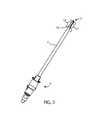
- FIG. 1is an isometric view of a tissue resection device
- FIG. 2is a side view of the tissue resection device of FIG. 1 ;
- FIG. 3is a bottom view of the tissue resection device of FIG. 1 ;
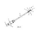
- FIG. 4is an isometric view of the tissue resection device of FIG. 1 with a hollow member removed;
- FIG. 5is an isometric view of another tissue resection device which incorporates an outer sheath with a protective hood;
- FIG. 6is a side view of the tissue resection device of FIG. 5 with the protective hood positioned in a first position;
- FIG. 7is a side view of the tissue resection device of FIG. 5 with the protective hood positioned in a second position;
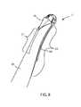
- FIG. 8is a close-up side view of the tissue resection device of FIG. 6 with the protective hood in the first position;
- FIG. 9is a close-up side view of this tissue resection device of FIG. 7 with the protective hood in the second position.
- a sagittal planedivides a body into right and left portions.
- a mid-sagittal planedivides the body into bilaterally symmetric right and left halves.
- a coronal planedivides a body into anterior and posterior portions.
- a transverse planedivides a body into superior and inferior portions.
- Anteriormeans toward the front of the body.
- Posteriormeans toward the back of the body.
- Superiormeans toward the head.
- Inferiormeans toward the feet.
- Medialmeans toward the midline of the body. Lateral means away from the midline of the body.
- Axialmeans toward a central axis of the body.
- Abaxialmeans away from a central axis of the body.
- FAIfemoroacetabular impingement
- a tissue resection device 1may include a drive adapter hub 2 , a hollow member 3 , and a rotary cutting member 7 .
- the hollow member 3has a proximal end 5 , a distal end 4 , and a central axis 6 .
- the drive adapter hub 2is coupled to the hollow member 3 at the proximal end 5 .
- the rotary cutting member 7is disposed at the distal end 4 of the hollow member 3 .
- the rotary cutting member 7may be described as a burr.
- the tissue resection device 1may also incorporate a suction port 8 to aid in removing tissue debris.
- the drive adapter hub 2may be adapted for grasping the tissue resection device and manipulating the position of the tissue resection device in any direction or orientation.
- the drive adapter hub 2may be adapted to interact with a powered hand piece (not shown) forming a handle for grasping the tissue resection device and manipulating the position of the tissue resection device in any direction or orientation.
- the drive adapter hub 2may include an integral handle formed thereon.
- the drive adapter hub 2may be externally textured or may have a high friction outer surface for grasping.
- FIG. 2shows the tissue resection device 1 from a side view.
- the hollow member 3may have an opening or window 17 formed in the distal end 4 of the hollow member 3 .
- the opening or window 17may be formed along the axis 6 of the hollow member 3 and sized and shaped to allow the rotary cutting member 7 to be partially exposed and protrude from the window 17 .
- the shape of the window 17 in the direction of the axis 6 of the hollow member 3may have edges 19 that are concave shaped and substantially similar to the concave shape of the rotary cutting member 7 .
- the rotary cutting member 7may protrude uniformly past the edges 19 .
- the concave shaped edges 19 of the window 17may thus act as depth stops to limit the amount of tissue that is resected during a single pass of the tissue resection device 1 .
- the rotary cutting member 7protrudes about 1.5 mm past the concave shaped edges 19 of the window 17 . In other examples, the rotary cutting member 7 protrudes less than 1.5 mm beyond the concave shaped edges 19 of the window 17 . In still other examples, the rotary cutting member 7 protrudes more than 1.5 mm beyond the concave shaped edges 19 of the window 17 . In some examples, the user may selectively adjust the amount that the rotary cutting member 7 protrudes from the concave shaped edges 19 of the window 17 .
- the concave shaped edges 19may also give the user better control by contacting the tissue during resection on one or both sides of the rotary cutting member 7 .
- the edges 19may provide stability to the resection device 1 by resisting twisting forces caused by the rotary cutting member as it spins and resects tissue.
- the edges 19may also provide stability to the resection device by providing a multi-contact stabilizing reference to help the user keep the burr or rotary cutting member 7 in the desired position, similar to a tripod or a tool rest.
- first contact point or area between the burr 7 and the tissueas the burr 7 resects the tissue; a second contact point or area between the tissue and a first concave shaped edge 19 , and a third contact point or area between the tissue and a second concave shaped edge 19 opposite the first concave shaped edge.
- Each additional contact pointprovides greater stability and control to the user.
- a distal top portion 18 of the hollow member 3may be entirely or partially formed of transparent material to allow the user to see the rotary cutting member 7 during use.
- the rotary cutting member 7may be fully exposed with no distal top portion 18 or protective hood 21 (discussed below) adjacent the rotary cutting member 7 , or any window 17 with concave shaped edges 19 to act as depth stops.
- FIG. 3shows a bottom view of the tissue resection device 1 illustrating the window 17 formed in the hollow member 3 and the concave or hourglass shaped rotary cutting member 7 exposed through the window 17 .
- the rotary cutting member 7may have an elongated body 9 that lies along an elongate body central longitudinal axis 27 .
- the rotary cutting member 7may be coaxial with the axis 6 of the hollow member 3 .
- the axis 27may be parallel to the axis 6 .
- FIG. 4shows the tissue resection device 1 with the hollow member 3 removed to expose a drive member 16 .
- the drive member 16may transmit rotational forces, or torque, from the hub 2 .
- the hub 2may transmit torque from a powered hand piece (not shown), which may be connected to a suitable power source (not shown).
- the hub 2may include a drive feature 31 , for example a triangular, rectangular, square, or hexagonal shaft, for complementary interconnection with the powered hand piece.
- the rotary cutting member 7may have one or more cutting features on the elongate body 9 .
- FIG. 4shows an example with cutting flutes along the length of the elongate body 9 of the rotary cutting member 7 .
- the cutting flutesmay be of any size, shape, or number.
- the cutting flutesmay be axial as shown, or they may be helical clockwise or counterclockwise.
- the cutting flutesmay cross to produce a diamond pattern of cutting projections.
- the rotary cutting member 7may have a first portion 12 , a second portion 14 , a third or middle portion 13 , and a fourth portion 15 .
- the rotary cutting member 7may have a concave or hourglass shape between the proximal end 10 and the distal end 11 of the rotary cutting member 7 .
- the first portion 12may have a first width or diameter
- the second portion 14may have a second width or diameter
- the middle portion 13may have a third width or diameter.
- the first width of the first portion 12 and the second width of the second portion 14may be greater than the third width of the middle portion 13 to form a concave curve between the first portion 12 and the second portion 14 of the rotary cutting member 7 .
- the first, second, and third widths or diametersmay be measured over the cutting features, and may thus correspond to the dimensions cut by the rotary cutting member 7 .
- the concave shape of the rotary cutting member 7may be chosen to substantially correspond to the natural or desired curvature of the tissue to be resected.
- the concave shape of the rotary cutting member 7may be chosen to substantially correspond to the natural curvature of the femoral neck of a human bone. In other examples, the concave shape of the rotary cutting member 7 may be chosen to substantially correspond to the natural or desired curvature of any tissue including, but not limited to, any bone, cartilage, soft tissue, and the like.
- rotary cutting member 7may have a fourth portion or end cutter 15 formed on the distal end 11 of the elongate body 9 of the rotary cutting member 7 .
- the end cutter portion 15is at least partially hemispherical in shape.
- the end cutter portion 15may be substantially flat, conical, dished, or another shape.
- the end cutter portion 15may have flutes, cutting members, or abrasive material formed thereon and configured to resect tissue.
- the end cutter portion 15may be useful in removing pincer-type bone impingements on an acetabular rim during femoral acetabular impingement (FAI) surgery.
- the rotary cutting member 7may terminate in a smooth non-cutting end portion instead of an end cutter.
- FIGS. 5-9illustrate another tissue resection device 40 that is similar to device 1 , but includes an outer sheath 20 having a protective hood 21 and a protective hood window 23 formed on the distal end of the outer sheath 20 .
- the outer sheath 20is a tubular structure that fits over a hollow member 3 .
- the protective hood window 23may be similar to window 17 .
- the window 23may be formed along the axis 6 of the hollow member 3 and sized and shaped to allow the rotary cutting member 7 to be partially exposed and protrude from the protective hood window 23 formed in the hollow member 3 .
- the shape of the protective hood window 23 in the direction of the axis 6 of the hollow member 3may have edges 24 that are concave and substantially similar to the concave shape of the rotary cutting member 7 .
- the concave shaped edges 24 of the protective hood window 23may thus act as depth stops to limit the amount of tissue that is resected during a single pass of the tissue resection device 40 .
- the protective hoodmay be made of transparent material to help the user visualize the placement and action of the rotary cutting member 7 .
- the outer sheath 20may be rotated by manipulating the control member 25 located at a proximal end of the outer sheath 20 .
- a usermay apply compressive and/or rotational forces to tabs 26 of the control member 25 to rotate the outer sheath 20 about the hollow member 3 and control the position of the protective hood 21 relative to the rotary cutting member 7 .
- the protective hood 21may be selectively positioned to expose the rotary cutting member 7 to allow tissue to be resected, or positioned to cover the rotary cutting member 7 to prevent tissue from being resected, or positioned to partially cover the rotary cutting member 7 .
- FIGS. 5, 6, and 8show the tissue resection device 40 with the outer sheath 20 rotationally oriented such that the protective hood window 23 of the outer sheath 20 is aligned with the window 17 of the hollow member 3 .
- Thisallows the rotary cutting member to be exposed through both windows 23 , 27 and enables the rotary cutting member 7 to resect tissue.
- FIGS. 7 and 9show the tissue resection device 40 with the outer sheath 20 rotationally oriented such that the protective hood window 23 of the outer sheath 20 faces the window 17 of the hollow member 3 . This covers up the rotary cutting member 7 and prevents the rotary cutting member 7 from resecting tissue along the curved portion of the rotary cutting member 7 .
- the end-cutting portion 15 of the rotary cutting member 7always remains exposed at the distal tip of the tissue resection device 40 regardless of the rotational orientation of the outer sheath 20 .
- the end-cutting portion 15 of the rotary cutting member 7may be selectively covered or uncovered to allow or prevent the end-cutting portion 15 from resecting tissue.
- the outer sheath 20 and the hollow member 3may extend distally to cover some of the end-cutting portion 15 . When the protective hood window 23 of the outer sheath 20 is aligned with the window 17 of the hollow member 3 , some of the end-cutting portion 15 is exposed.
- the outer sheath 20may be translatable along the axis 6 of the hollow member 3 to cover portions of the rotary cutting member 7 .
- the outer sheath 20may be translated in the distal direction to substantially cover up all or a portion of the hourglass and/or end cutting portions 15 of the tissue resection device 40 .
- the outer sheath 20may be both rotatably and axially positionable.
- a rotatable or translatable protective hood 21may be used with any surgical instrument, besides burrs, to cover up the end effector disposed at the distal end of the hollow member 3 .
- Example end effectorsinclude, but are not limited to: grasping jaws, dissectors, suture passers, staplers, tissue cutters, rasps, ablation devices, microfracture devices, scalpels, shavers, cameras, sensors, etc., or any other end effector or structure.
- FIG. 8it may be seen that when the outer sheath 20 is rotated to the open position, the rotary cutting member 7 and the suction port are exposed through the window 23 and the suction created by suction port 8 is proximal to the rotary cutting member 7 .
- suction poweris positioned close to the curved portion of the rotary cutting member 7 where it is needed to remove tissue debris.
- the protective hood 21covers the curved portion of the rotary cutting member 7 and the suction port 8 . This directs suction distally toward the end-cutting portion 15 of the rotary cutting member 7 , as may be seen in FIG. 9 .
- the design of the outer sheath 20automatically shifts fluid suction between the proximal part of the rotary cutting member 7 to the distal end-cutting portion 15 of the rotary cutting member 7 as the outer sheath 20 is rotated.
- the outer sheath 20may be axially translatable to automatically direct fluid suction forces between the proximal part of the rotary cutting member 7 and the distal end-cutting portion 15 of the rotary cutting member as the outer sheath 20 translates back and forth in the axial direction.
- the components disclosed hereinmay be fabricated from metals, alloys, polymers, plastics, ceramics, glasses, composite materials, or combinations thereof, including but not limited to: PEEK, titanium, titanium alloys, commercially pure titanium grade 2, ASTM F67, Nitinol, cobalt chrome, stainless steel, ultra high molecular weight polyethylene (UHMWPE), biocompatible materials, and biodegradable materials, among others. Different materials may be used for different parts. Different materials may be used within a single part. Any component disclosed herein may be colored, coded or otherwise marked to make it easier for a user to identify the type and size of the component, the setting, the function(s) of the component, and the like.
- Coupledis defined as connected, although not necessarily directly, and not necessarily mechanically.
- a step of a method or an element of a devicethat “comprises,” “has,” “includes” or “contains” one or more features, possesses those one or more features, but is not limited to possessing only those one or more features.
- a device or structure that is configured in a certain wayis configured in at least that way, but may also be configured in ways that are not listed.
Landscapes
- Health & Medical Sciences (AREA)
- Surgery (AREA)
- Life Sciences & Earth Sciences (AREA)
- Medical Informatics (AREA)
- Animal Behavior & Ethology (AREA)
- Engineering & Computer Science (AREA)
- Biomedical Technology (AREA)
- Heart & Thoracic Surgery (AREA)
- Veterinary Medicine (AREA)
- Molecular Biology (AREA)
- Nuclear Medicine, Radiotherapy & Molecular Imaging (AREA)
- General Health & Medical Sciences (AREA)
- Public Health (AREA)
- Orthopedic Medicine & Surgery (AREA)
- Dentistry (AREA)
- Oral & Maxillofacial Surgery (AREA)
- Surgical Instruments (AREA)
Abstract
Description
Claims (13)
Priority Applications (2)
| Application Number | Priority Date | Filing Date | Title |
|---|---|---|---|
| US13/763,084US9629646B2 (en) | 2012-07-11 | 2013-02-08 | Curved burr surgical instrument |
| US15/492,778US20170215907A1 (en) | 2012-07-11 | 2017-04-20 | Curved surgical burr |
Applications Claiming Priority (2)
| Application Number | Priority Date | Filing Date | Title |
|---|---|---|---|
| US201261670540P | 2012-07-11 | 2012-07-11 | |
| US13/763,084US9629646B2 (en) | 2012-07-11 | 2013-02-08 | Curved burr surgical instrument |
Related Child Applications (1)
| Application Number | Title | Priority Date | Filing Date |
|---|---|---|---|
| US15/492,778ContinuationUS20170215907A1 (en) | 2012-07-11 | 2017-04-20 | Curved surgical burr |
Publications (2)
| Publication Number | Publication Date |
|---|---|
| US20140018834A1 US20140018834A1 (en) | 2014-01-16 |
| US9629646B2true US9629646B2 (en) | 2017-04-25 |
Family
ID=49914626
Family Applications (2)
| Application Number | Title | Priority Date | Filing Date |
|---|---|---|---|
| US13/763,084Expired - Fee RelatedUS9629646B2 (en) | 2012-07-11 | 2013-02-08 | Curved burr surgical instrument |
| US15/492,778AbandonedUS20170215907A1 (en) | 2012-07-11 | 2017-04-20 | Curved surgical burr |
Family Applications After (1)
| Application Number | Title | Priority Date | Filing Date |
|---|---|---|---|
| US15/492,778AbandonedUS20170215907A1 (en) | 2012-07-11 | 2017-04-20 | Curved surgical burr |
Country Status (1)
| Country | Link |
|---|---|
| US (2) | US9629646B2 (en) |
Cited By (1)
| Publication number | Priority date | Publication date | Assignee | Title |
|---|---|---|---|---|
| US20170215907A1 (en)* | 2012-07-11 | 2017-08-03 | Jens Kather | Curved surgical burr |
Families Citing this family (9)
| Publication number | Priority date | Publication date | Assignee | Title |
|---|---|---|---|---|
| GB2521224A (en)* | 2013-12-16 | 2015-06-17 | Nordic Semiconductor Asa | Radio communications |
| EP3090412A2 (en)* | 2013-12-31 | 2016-11-09 | Huf North America Automotive Parts Mfg. Corp. | Bluetooth verification for vehicle access systems |
| US9055967B1 (en)* | 2014-11-07 | 2015-06-16 | Oscar R Polo | Tissue severing device having dual reciprocating looped blades and methods of use |
| DE102015208646A1 (en) | 2015-05-08 | 2016-11-10 | Frank Zastrow | Surgical hand-held device and a protective device |
| DE102015209769A1 (en)* | 2015-05-28 | 2016-12-01 | Frank Zastrow | Surgical hand tool and a tool and a protective device |
| US10631882B2 (en)* | 2016-04-28 | 2020-04-28 | David K. Boger | Oscillating decortication burr assembly |
| JP7569840B2 (en) | 2019-08-14 | 2024-10-18 | エルエスアイ ソルーションズ インコーポレーテッド | Device for blood vessel harvesting |
| CN111671497A (en)* | 2020-05-25 | 2020-09-18 | 北京市春立正达医疗器械股份有限公司 | Medical planing device |
| US20220233270A1 (en)* | 2021-01-22 | 2022-07-28 | Lsi Solutions, Inc. | Minimally invasive surgical device for vessel harvesting |
Citations (148)
| Publication number | Priority date | Publication date | Assignee | Title |
|---|---|---|---|---|
| US1314601A (en) | 1919-09-02 | Flexible shaft | ||
| US1630239A (en) | 1924-05-09 | 1927-05-24 | Roy S Binkley | Antrum burr |
| US1677337A (en) | 1924-09-27 | 1928-07-17 | Thomas E Grove | Antrum drill |
| USRE29736E (en) | 1975-10-22 | 1978-08-22 | Xomed Inc. | High speed bone drill |
| US4264307A (en) | 1979-08-20 | 1981-04-28 | Neuwirth Siegmund A | Dental reducing tool |
| US4285618A (en) | 1979-10-12 | 1981-08-25 | Shanley Stephen E Jr | Rotary milling cutter |
| US4445509A (en) | 1982-02-04 | 1984-05-01 | Auth David C | Method and apparatus for removal of enclosed abnormal deposits |
| US4541423A (en) | 1983-01-17 | 1985-09-17 | Barber Forest C | Drilling a curved hole |
| US4646738A (en) | 1985-12-05 | 1987-03-03 | Concept, Inc. | Rotary surgical tool |
| US4751922A (en) | 1986-06-27 | 1988-06-21 | Dipietropolo Al | Flexible medullary reamer |
| US4842578A (en) | 1986-03-12 | 1989-06-27 | Dyonics, Inc. | Surgical abrading instrument |
| GB2220729A (en) | 1988-07-15 | 1990-01-17 | Bristol Myers Co | Angle drive device |
| DE3840466A1 (en) | 1988-12-01 | 1990-06-07 | Lieke Michael | Special cutters for use in implant technology |
| US4950277A (en) | 1989-01-23 | 1990-08-21 | Interventional Technologies, Inc. | Atherectomy cutting device with eccentric wire and method |
| US4984581A (en) | 1988-10-12 | 1991-01-15 | Flexmedics Corporation | Flexible guide having two-way shape memory alloy |
| US4990134A (en) | 1986-01-06 | 1991-02-05 | Heart Technology, Inc. | Transluminal microdissection device |
| US5047040A (en) | 1987-11-05 | 1991-09-10 | Devices For Vascular Intervention, Inc. | Atherectomy device and method |
| US5067489A (en) | 1988-08-16 | 1991-11-26 | Flexmedics Corporation | Flexible guide with safety tip |
| US5069569A (en) | 1991-05-09 | 1991-12-03 | Ferro Tools Inc. | Universal joint |
| US5147364A (en) | 1981-08-20 | 1992-09-15 | Ohio Medical Instrument Company | Osteotomy saw/file, cutting guide and method |
| WO1992015255A1 (en) | 1991-03-06 | 1992-09-17 | Bowen & Co., Inc. | Method and apparatus for material removal |
| CN2134842Y (en) | 1991-12-29 | 1993-06-02 | 中国人民武装警察部队吉林省总队医院 | Multi-functional drill or saw for bones |
| US5226909A (en) | 1989-09-12 | 1993-07-13 | Devices For Vascular Intervention, Inc. | Atherectomy device having helical blade and blade guide |
| US5322505A (en) | 1990-02-07 | 1994-06-21 | Smith & Nephew Dyonics, Inc. | Surgical instrument |
| US5360432A (en) | 1992-10-16 | 1994-11-01 | Shturman Cardiology Systems, Inc. | Abrasive drive shaft device for directional rotational atherectomy |
| US5387218A (en) | 1990-12-06 | 1995-02-07 | University College London | Surgical instrument for shaping a bone |
| US5411514A (en) | 1992-09-30 | 1995-05-02 | Linvatec Corporation | Bendable variable angle rotating shaver |
| US5468243A (en) | 1993-10-27 | 1995-11-21 | Halpern; Alan A. | Femoral superior neck remodelling means and method |
| US5488761A (en) | 1994-07-28 | 1996-02-06 | Leone; Ronald P. | Flexible shaft and method for manufacturing same |
| US5527316A (en) | 1994-02-23 | 1996-06-18 | Stone; Kevin T. | Surgical reamer |
| US5554163A (en) | 1995-04-27 | 1996-09-10 | Shturman Cardiology Systems, Inc. | Atherectomy device |
| US5556408A (en) | 1995-04-27 | 1996-09-17 | Interventional Technologies Inc. | Expandable and compressible atherectomy cutter |
| US5569284A (en) | 1994-09-23 | 1996-10-29 | United States Surgical Corporation | Morcellator |
| US5584843A (en) | 1994-12-20 | 1996-12-17 | Boston Scientific Corporation | Shaped wire multi-burr rotational ablation device |
| US5620447A (en) | 1993-01-29 | 1997-04-15 | Smith & Nephew Dyonics Inc. | Surgical instrument |
| US5759185A (en) | 1994-10-24 | 1998-06-02 | Smith & Nephew, Inc. | Surgical instrument |
| US5810827A (en)* | 1994-09-02 | 1998-09-22 | Hudson Surgical Design, Inc. | Method and apparatus for bony material removal |
| US5851208A (en) | 1996-10-15 | 1998-12-22 | Linvatec Corporation | Rotatable surgical burr |
| US5904681A (en) | 1997-02-10 | 1999-05-18 | Hugh S. West, Jr. | Endoscopic surgical instrument with ability to selectively remove different tissue with mechanical and electrical energy |
| US5908423A (en) | 1993-05-27 | 1999-06-01 | Howmedica, Inc. | Flexible medullary reaming system |
| US5913867A (en) | 1996-12-23 | 1999-06-22 | Smith & Nephew, Inc. | Surgical instrument |
| US6027460A (en) | 1995-09-14 | 2000-02-22 | Shturman Cardiology Systems, Inc. | Rotatable intravascular apparatus |
| US6053907A (en) | 1998-08-13 | 2000-04-25 | Endius Incorporated | Surgical instruments with flexible drive shaft |
| US6053922A (en) | 1995-07-18 | 2000-04-25 | Krause; William R. | Flexible shaft |
| US6053923A (en) | 1998-03-17 | 2000-04-25 | Arthrotek, Inc. | Method and apparatus for abrading tissue |
| US6068641A (en) | 1998-08-25 | 2000-05-30 | Linvatec Corporation | Irrigated burr |
| US6126667A (en) | 1999-10-01 | 2000-10-03 | Scimed Life Systems, Inc. | Articulated ablation device |
| US6197064B1 (en) | 1994-09-02 | 2001-03-06 | Hudson Surgical Design, Inc. | Prosthetic implant |
| US6214009B1 (en) | 1998-09-09 | 2001-04-10 | Xomed Surgical Products, Inc. | Rhinoplasty bur |
| US6217595B1 (en) | 1996-11-18 | 2001-04-17 | Shturman Cardiology Systems, Inc. | Rotational atherectomy device |
| US6235042B1 (en) | 1998-09-21 | 2001-05-22 | Arteria Medical Science, Inc. | Atherectomy device |
| US6299623B1 (en) | 1999-02-03 | 2001-10-09 | Scimed Life Systems, Inc. | Atherectomy burr including a bias wire |
| US20010034526A1 (en) | 2000-02-15 | 2001-10-25 | Kuslich Stephen D. | Expandable reamer |
| US6312438B1 (en) | 2000-02-01 | 2001-11-06 | Medtronic Xomed, Inc. | Rotary bur instruments having bur tips with aspiration passages |
| US6358251B1 (en) | 2000-03-21 | 2002-03-19 | University Of Washington | Method and apparatus for forming a cavity in soft tissue or bone |
| US6423078B1 (en) | 1999-04-23 | 2002-07-23 | Medtronic Xomed, Inc. | Dermabrasion instrument, instrument assembly and method |
| US6482209B1 (en) | 2001-06-14 | 2002-11-19 | Gerard A. Engh | Apparatus and method for sculpting the surface of a joint |
| US20030055404A1 (en) | 2001-09-17 | 2003-03-20 | Moutafis Timothy E. | Endoscopic rotary abraders |
| US6638288B1 (en) | 1997-08-14 | 2003-10-28 | Shturman Cardiology Systems, Inc. | Eccentric drive shaft for atherectomy device and method for manufacture |
| US6645218B1 (en) | 2002-08-05 | 2003-11-11 | Endius Incorporated | Surgical instrument |
| US6656195B2 (en) | 2000-09-22 | 2003-12-02 | Medtronic Xomed, Inc. | Flexible inner tubular members and rotary tissue cutting instruments having flexible inner tubular members |
| EP1389458A1 (en) | 2001-04-27 | 2004-02-18 | Nagashima Medical Instruments Co., Ltd | Medical rinsing and sucking device |
| US20040098006A1 (en) | 2002-07-16 | 2004-05-20 | Takasuke Nakanishi | Medical handpiece and cutting tool therefor |
| US6740090B1 (en) | 2000-02-16 | 2004-05-25 | Trans1 Inc. | Methods and apparatus for forming shaped axial bores through spinal vertebrae |
| US20040147934A1 (en) | 2002-10-18 | 2004-07-29 | Kiester P. Douglas | Oscillating, steerable, surgical burring tool and method of using the same |
| WO2004075719A2 (en) | 2003-02-24 | 2004-09-10 | Senorx, Inc. | Biopsy device with inner cutting member |
| WO2004110251A2 (en) | 2003-05-30 | 2004-12-23 | Hedley Anthony K | Surgical tools for joint replacement |
| US20050113836A1 (en) | 2003-11-25 | 2005-05-26 | Lozier Antony J. | Expandable reamer |
| US20050197661A1 (en) | 2004-03-03 | 2005-09-08 | Scimed Life Systems, Inc. | Tissue removal probe with sliding burr in cutting window |
| US20050203527A1 (en) | 2004-03-03 | 2005-09-15 | Scimed Life Systems, Inc. | Apparatus and methods for removing vertebral bone and disc tissue |
| US20050203508A1 (en) | 2000-03-07 | 2005-09-15 | Thelen Sarah L. | Method and apparatus for reducing femoral fractures |
| US20050209610A1 (en) | 2004-03-03 | 2005-09-22 | Scimed Life Systems, Inc. | Radially adjustable tissue removal device |
| US6949101B2 (en) | 2002-03-29 | 2005-09-27 | Depuy Orthopaedics, Inc. | Medical instrument for milling a curved path in bone and procedure |
| US20050234477A1 (en) | 2002-05-22 | 2005-10-20 | Brown Eva M | Method and apparatus for treating skin |
| DE102004046539A1 (en) | 2004-09-21 | 2006-04-13 | Aesculap Ag & Co. Kg | Surgical instrument, in particular endoscopic shaver, comprising segments of inner tube with convex surfaces |
| US20060142775A1 (en) | 2004-12-29 | 2006-06-29 | Depuy Mitek, Inc. | Surgical tool with cannulated rotary tip |
| US20060149268A1 (en) | 2004-11-19 | 2006-07-06 | Csaba Truckai | Bone treatment systems and methods |
| US20060178594A1 (en) | 2005-02-07 | 2006-08-10 | Neubardt Seth L | Apparatus and method for locating defects in bone tissue |
| US20060217751A1 (en) | 2005-03-02 | 2006-09-28 | O'quinn Philip S | Endoscopic rotary abrader |
| US7118574B2 (en) | 2002-06-14 | 2006-10-10 | Ethicon, Inc | Arthroscopic bone burr device |
| GB2426455A (en) | 2005-05-26 | 2006-11-29 | Leonid Shturman | A rotational atherectomy device with supports on the drive shaft |
| WO2007003243A1 (en) | 2005-07-05 | 2007-01-11 | Plus Orthopedics Ag | Bone cutter |
| US20070060933A1 (en)* | 2005-07-11 | 2007-03-15 | Meera Sankaran | Curette heads |
| EP1787593A1 (en) | 2004-05-19 | 2007-05-23 | Sintea Biotech S.p.A. | Device for creating bone cavities |
| US20070118135A1 (en) | 2005-11-23 | 2007-05-24 | Mansmann Kevin A | Surgical tools with extendible and rotatable accessory components |
| US20070197895A1 (en) | 2006-02-17 | 2007-08-23 | Sdgi Holdings, Inc. | Surgical instrument to assess tissue characteristics |
| US20070260256A1 (en) | 2006-05-05 | 2007-11-08 | Beaule Paul E | Surgical instrument tray, hip resurfacing kit, and method of resurfacing a femoral head to preserve femoral head vascularity |
| CN201055399Y (en) | 2006-11-14 | 2008-05-07 | 梁雄 | Electric saw tool head for orthopedic operation |
| US7393355B2 (en) | 2003-02-04 | 2008-07-01 | Howmedica Osteonics Corp. | Femoral guide and pivoting reamer |
| US20080208230A1 (en) | 2007-02-22 | 2008-08-28 | Singfatt Chin | Expandable rotating device and method for tissue aspiration |
| US20090048602A1 (en) | 2007-08-15 | 2009-02-19 | O'donoghue Denis | Surgical bur with unequally spaced flutes, flutes with different rake angles and flutes with alternating reliefs |
| US7507245B2 (en) | 2001-10-19 | 2009-03-24 | Cardiovascular Systems, Inc. | Rotational angioplasty device with abrasive crown |
| CN101433468A (en) | 2008-12-16 | 2009-05-20 | 张纯朴 | Device for cutting bone inside femoral head |
| US7555343B2 (en) | 2004-10-15 | 2009-06-30 | Baxano, Inc. | Devices and methods for selective surgical removal of tissue |
| US7559928B2 (en) | 2002-02-12 | 2009-07-14 | Alexandria Research Technologies, Llc | Apparatus and method for minimally invasive total joint replacement |
| US7585300B2 (en)* | 2003-12-19 | 2009-09-08 | Spinascope, Inc. | Dissecting high speed burr for spinal surgery |
| US7604637B2 (en) | 2001-06-14 | 2009-10-20 | Alexandria Research Technologies, Llc | Apparatus and method for minimally invasive total joint replacement |
| US20090270894A1 (en) | 2008-04-25 | 2009-10-29 | Joshua David Rubin | Surgical instrument with internal irrigation |
| US7637910B2 (en) | 2006-03-21 | 2009-12-29 | Arthrex, Inc. | Method of ACL reconstruction using dual-sided rotary drill cutter |
| US20090326538A1 (en) | 2006-12-15 | 2009-12-31 | Sennett Andrew R | Devices and methods for fracture reduction |
| US7682378B2 (en) | 2004-11-10 | 2010-03-23 | Dfine, Inc. | Bone treatment systems and methods for introducing an abrading structure to abrade bone |
| WO2010033473A2 (en) | 2008-09-18 | 2010-03-25 | Smith & Nephew, Inc. | Apparatus and method for addressing femoral acetabular impingement |
| US20100121365A1 (en) | 2005-07-19 | 2010-05-13 | O'sullivan Denis F | Surgical bur with anti-chatter flute geometry |
| US7717932B2 (en) | 2005-10-27 | 2010-05-18 | Medtronic Xomed, Inc. | Instrument and system for surgical cutting and evoked potential monitoring |
| US20100145343A1 (en) | 2007-04-04 | 2010-06-10 | Alexandria Research Technologies, Llc | Apparatus and method for sculpting the surface of a joint |
| US20100152738A1 (en) | 2008-12-17 | 2010-06-17 | Kenneth Holko | Advanced burr, applique for a burr and method of fabricating |
| US20100179557A1 (en) | 2009-01-15 | 2010-07-15 | Husted Daniel S | Adjustable Powered Rongeur |
| US7785337B2 (en) | 2003-09-09 | 2010-08-31 | Medtronic Xomed, Inc. | Surgical micro-burring instrument and method of performing sinus surgery |
| US20100229688A1 (en) | 2005-08-30 | 2010-09-16 | Adams Kenneth M | Spiral cut curved blade |
| US20100266984A1 (en) | 2009-04-17 | 2010-10-21 | Jung Sung Min | Bur for maxillary sinus augmentation |
| US20100280624A1 (en) | 2001-06-14 | 2010-11-04 | Alexandria Research Technologies, Llc | Modular apparatus and method for sculpting the surface of a joint |
| US20100286698A1 (en) | 2009-05-08 | 2010-11-11 | Del Rio Eddy H | Disposable burr attachment |
| US20100286694A1 (en) | 2009-05-08 | 2010-11-11 | Rio Eddy H Del | Surgical drill with curved burr attachment and method |
| US20100298832A1 (en) | 2009-05-20 | 2010-11-25 | Osseon Therapeutics, Inc. | Steerable curvable vertebroplasty drill |
| US20110004215A1 (en) | 2005-09-12 | 2011-01-06 | Bradley James P | Labrum retracting burr |
| US20110015639A1 (en) | 2006-02-27 | 2011-01-20 | Biomet Manufacturing Corp. | Femoral Acetabular Impingement Guide |
| US20110034930A1 (en) | 2008-02-29 | 2011-02-10 | Buschmann Michael D | Drill burr and method for performing holes in subchondral bone to promote cartilage repair |
| US7896880B2 (en) | 1990-06-28 | 2011-03-01 | P Tech, Llc | Apparatus and method for tissue removal |
| WO2011023410A1 (en) | 2009-08-31 | 2011-03-03 | Stryker Ireland, Ltd. | Surgical cutting accessory with flexible tube |
| US7918796B2 (en) | 2006-04-11 | 2011-04-05 | Warsaw Orthopedic, Inc. | Volumetric measurement and visual feedback of tissues |
| US7922720B2 (en) | 2005-03-31 | 2011-04-12 | Zimmer Technology, Inc. | Orthopaedic cutting instrument and method |
| US7935117B2 (en) | 2007-05-02 | 2011-05-03 | Depuy Products, Inc. | Expandable proximal reamer |
| WO2011060077A1 (en) | 2009-11-10 | 2011-05-19 | Spine View, Inc. | Angled grinder |
| US20110125160A1 (en) | 2009-11-20 | 2011-05-26 | Knee Creations, Llc | Instruments for targeting a joint defect |
| US7985225B2 (en) | 2003-05-05 | 2011-07-26 | Alexandria Research Technologies, Llc | Apparatus and method for sculpting the surface of a joint |
| US20110196399A1 (en)* | 2010-02-11 | 2011-08-11 | Ethicon Endo-Surgery, Inc. | Ultrasonic surgical instruments with rotatable blade and hollow sheath arrangements |
| US8006578B2 (en) | 2005-10-12 | 2011-08-30 | Kiester Douglas P | Apparatus and method for a high speed rotation-to-rotation oscillation converter for surgical use |
| US20110238099A1 (en) | 2010-03-24 | 2011-09-29 | Smith & Nephew, Inc. | Arthroscopic Resection Devices |
| US20110270293A1 (en) | 2010-04-30 | 2011-11-03 | Medtronic Xomed, Inc. | Powered surgical tissue cutting instrument having an irrigation system |
| US8070762B2 (en) | 2007-10-22 | 2011-12-06 | Atheromed Inc. | Atherectomy devices and methods |
| US20110319896A1 (en) | 2010-06-23 | 2011-12-29 | Papenfuss Erik H | Cannulated flexible drive shaft |
| US20120004662A1 (en) | 2010-06-30 | 2012-01-05 | Paul Alexander Torrie | Resection Instrument |
| WO2012004766A2 (en) | 2010-07-07 | 2012-01-12 | Yoseph Weitzman | Surgical device for tissue removal |
| US8114083B2 (en) | 2004-01-14 | 2012-02-14 | Hudson Surgical Design, Inc. | Methods and apparatus for improved drilling and milling tools for resection |
| US20120046526A1 (en) | 2010-08-21 | 2012-02-23 | New York Society For The Ruptured And Crippled Maintaining The Hospital For Special Surgery | Instruments for use in femoroacetabular impingement procedures |
| US8123750B2 (en) | 2005-08-17 | 2012-02-28 | Corespine Technologies, Llc | Apparatus and methods for removal of intervertebral disc tissues |
| EP2426456A1 (en) | 2009-04-30 | 2012-03-07 | YKK Corporation | Device for measuring thickness of cloth and method for measuring thickness of cloth |
| US20120083788A1 (en) | 2010-10-01 | 2012-04-05 | Vot, Llc | Bur guide attachment and method of use |
| US8157825B2 (en) | 2006-07-13 | 2012-04-17 | Lela Nadirashvili | Atherectomy device supported by fluid bearings |
| US8157766B2 (en) | 2005-09-01 | 2012-04-17 | Medrad, Inc. | Torqueable kink-resistant guidewire |
| US8172846B2 (en) | 2004-02-11 | 2012-05-08 | Medtronic Xomed, Inc. | Method for performing high speed surgical procedures |
| US20120116532A1 (en) | 2009-07-10 | 2012-05-10 | Milux Holdings SA | Hip joint device and method |
| US20120116405A1 (en) | 2008-04-04 | 2012-05-10 | Depuy Products, Inc. | Humeral rotating burr guide |
| US20120150209A1 (en) | 2009-08-26 | 2012-06-14 | Matteo Gubellini | Ribbed surgical bur |
| US20120209273A1 (en) | 2010-11-15 | 2012-08-16 | Zaretzka Gary D | Tissue removal system with retention mechanism |
| US20120221007A1 (en) | 2010-12-20 | 2012-08-30 | David Batten | Articulating tissue removal systems and methods |
| US20130023882A1 (en) | 2011-02-15 | 2013-01-24 | Fabro Myra I L | Discectomy devices and related methods |
| US8473305B2 (en) | 2007-04-17 | 2013-06-25 | Biomet Manufacturing Corp. | Method and apparatus for manufacturing an implant |
Family Cites Families (1)
| Publication number | Priority date | Publication date | Assignee | Title |
|---|---|---|---|---|
| US9629646B2 (en)* | 2012-07-11 | 2017-04-25 | Jens Kather | Curved burr surgical instrument |
- 2013
- 2013-02-08USUS13/763,084patent/US9629646B2/ennot_activeExpired - Fee Related
- 2017
- 2017-04-20USUS15/492,778patent/US20170215907A1/ennot_activeAbandoned
Patent Citations (157)
| Publication number | Priority date | Publication date | Assignee | Title |
|---|---|---|---|---|
| US1314601A (en) | 1919-09-02 | Flexible shaft | ||
| US1630239A (en) | 1924-05-09 | 1927-05-24 | Roy S Binkley | Antrum burr |
| US1677337A (en) | 1924-09-27 | 1928-07-17 | Thomas E Grove | Antrum drill |
| USRE29736E (en) | 1975-10-22 | 1978-08-22 | Xomed Inc. | High speed bone drill |
| US4264307B1 (en) | 1979-08-20 | 1987-06-02 | ||
| US4264307A (en) | 1979-08-20 | 1981-04-28 | Neuwirth Siegmund A | Dental reducing tool |
| US4285618A (en) | 1979-10-12 | 1981-08-25 | Shanley Stephen E Jr | Rotary milling cutter |
| US5147364A (en) | 1981-08-20 | 1992-09-15 | Ohio Medical Instrument Company | Osteotomy saw/file, cutting guide and method |
| US4445509A (en) | 1982-02-04 | 1984-05-01 | Auth David C | Method and apparatus for removal of enclosed abnormal deposits |
| US4541423A (en) | 1983-01-17 | 1985-09-17 | Barber Forest C | Drilling a curved hole |
| US4646738A (en) | 1985-12-05 | 1987-03-03 | Concept, Inc. | Rotary surgical tool |
| US4990134B1 (en) | 1986-01-06 | 1996-11-05 | Heart Techn Inc | Transluminal microdissection device |
| US4990134A (en) | 1986-01-06 | 1991-02-05 | Heart Technology, Inc. | Transluminal microdissection device |
| US4842578A (en) | 1986-03-12 | 1989-06-27 | Dyonics, Inc. | Surgical abrading instrument |
| US4751922A (en) | 1986-06-27 | 1988-06-21 | Dipietropolo Al | Flexible medullary reamer |
| US5047040A (en) | 1987-11-05 | 1991-09-10 | Devices For Vascular Intervention, Inc. | Atherectomy device and method |
| GB2220729A (en) | 1988-07-15 | 1990-01-17 | Bristol Myers Co | Angle drive device |
| US5067489A (en) | 1988-08-16 | 1991-11-26 | Flexmedics Corporation | Flexible guide with safety tip |
| US4984581A (en) | 1988-10-12 | 1991-01-15 | Flexmedics Corporation | Flexible guide having two-way shape memory alloy |
| DE3840466A1 (en) | 1988-12-01 | 1990-06-07 | Lieke Michael | Special cutters for use in implant technology |
| US4950277A (en) | 1989-01-23 | 1990-08-21 | Interventional Technologies, Inc. | Atherectomy cutting device with eccentric wire and method |
| US5226909A (en) | 1989-09-12 | 1993-07-13 | Devices For Vascular Intervention, Inc. | Atherectomy device having helical blade and blade guide |
| US5569277A (en)* | 1989-09-12 | 1996-10-29 | Devices For Vascular Intervention, Inc. | Atherectomy device having helical blade and blade guide |
| US5322505A (en) | 1990-02-07 | 1994-06-21 | Smith & Nephew Dyonics, Inc. | Surgical instrument |
| US7896880B2 (en) | 1990-06-28 | 2011-03-01 | P Tech, Llc | Apparatus and method for tissue removal |
| US5387218A (en) | 1990-12-06 | 1995-02-07 | University College London | Surgical instrument for shaping a bone |
| WO1992015255A1 (en) | 1991-03-06 | 1992-09-17 | Bowen & Co., Inc. | Method and apparatus for material removal |
| US5069569A (en) | 1991-05-09 | 1991-12-03 | Ferro Tools Inc. | Universal joint |
| CN2134842Y (en) | 1991-12-29 | 1993-06-02 | 中国人民武装警察部队吉林省总队医院 | Multi-functional drill or saw for bones |
| US5411514A (en) | 1992-09-30 | 1995-05-02 | Linvatec Corporation | Bendable variable angle rotating shaver |
| US5360432A (en) | 1992-10-16 | 1994-11-01 | Shturman Cardiology Systems, Inc. | Abrasive drive shaft device for directional rotational atherectomy |
| US5620447A (en) | 1993-01-29 | 1997-04-15 | Smith & Nephew Dyonics Inc. | Surgical instrument |
| US5908423A (en) | 1993-05-27 | 1999-06-01 | Howmedica, Inc. | Flexible medullary reaming system |
| US5468243A (en) | 1993-10-27 | 1995-11-21 | Halpern; Alan A. | Femoral superior neck remodelling means and method |
| US5527316A (en) | 1994-02-23 | 1996-06-18 | Stone; Kevin T. | Surgical reamer |
| US5488761A (en) | 1994-07-28 | 1996-02-06 | Leone; Ronald P. | Flexible shaft and method for manufacturing same |
| US5810827A (en)* | 1994-09-02 | 1998-09-22 | Hudson Surgical Design, Inc. | Method and apparatus for bony material removal |
| US6197064B1 (en) | 1994-09-02 | 2001-03-06 | Hudson Surgical Design, Inc. | Prosthetic implant |
| US5569284A (en) | 1994-09-23 | 1996-10-29 | United States Surgical Corporation | Morcellator |
| US5759185A (en) | 1994-10-24 | 1998-06-02 | Smith & Nephew, Inc. | Surgical instrument |
| US5584843A (en) | 1994-12-20 | 1996-12-17 | Boston Scientific Corporation | Shaped wire multi-burr rotational ablation device |
| US5556408A (en) | 1995-04-27 | 1996-09-17 | Interventional Technologies Inc. | Expandable and compressible atherectomy cutter |
| US5554163A (en) | 1995-04-27 | 1996-09-10 | Shturman Cardiology Systems, Inc. | Atherectomy device |
| US6053922A (en) | 1995-07-18 | 2000-04-25 | Krause; William R. | Flexible shaft |
| US6027460A (en) | 1995-09-14 | 2000-02-22 | Shturman Cardiology Systems, Inc. | Rotatable intravascular apparatus |
| US5851208A (en) | 1996-10-15 | 1998-12-22 | Linvatec Corporation | Rotatable surgical burr |
| US6217595B1 (en) | 1996-11-18 | 2001-04-17 | Shturman Cardiology Systems, Inc. | Rotational atherectomy device |
| US5913867A (en) | 1996-12-23 | 1999-06-22 | Smith & Nephew, Inc. | Surgical instrument |
| US5904681A (en) | 1997-02-10 | 1999-05-18 | Hugh S. West, Jr. | Endoscopic surgical instrument with ability to selectively remove different tissue with mechanical and electrical energy |
| US6638288B1 (en) | 1997-08-14 | 2003-10-28 | Shturman Cardiology Systems, Inc. | Eccentric drive shaft for atherectomy device and method for manufacture |
| US6053923A (en) | 1998-03-17 | 2000-04-25 | Arthrotek, Inc. | Method and apparatus for abrading tissue |
| US6053907A (en) | 1998-08-13 | 2000-04-25 | Endius Incorporated | Surgical instruments with flexible drive shaft |
| US6068641A (en) | 1998-08-25 | 2000-05-30 | Linvatec Corporation | Irrigated burr |
| US6214009B1 (en) | 1998-09-09 | 2001-04-10 | Xomed Surgical Products, Inc. | Rhinoplasty bur |
| US6235042B1 (en) | 1998-09-21 | 2001-05-22 | Arteria Medical Science, Inc. | Atherectomy device |
| US6299623B1 (en) | 1999-02-03 | 2001-10-09 | Scimed Life Systems, Inc. | Atherectomy burr including a bias wire |
| US6423078B1 (en) | 1999-04-23 | 2002-07-23 | Medtronic Xomed, Inc. | Dermabrasion instrument, instrument assembly and method |
| US6126667A (en) | 1999-10-01 | 2000-10-03 | Scimed Life Systems, Inc. | Articulated ablation device |
| US6312438B1 (en) | 2000-02-01 | 2001-11-06 | Medtronic Xomed, Inc. | Rotary bur instruments having bur tips with aspiration passages |
| US20010034526A1 (en) | 2000-02-15 | 2001-10-25 | Kuslich Stephen D. | Expandable reamer |
| US6740090B1 (en) | 2000-02-16 | 2004-05-25 | Trans1 Inc. | Methods and apparatus for forming shaped axial bores through spinal vertebrae |
| US20050203508A1 (en) | 2000-03-07 | 2005-09-15 | Thelen Sarah L. | Method and apparatus for reducing femoral fractures |
| US6358251B1 (en) | 2000-03-21 | 2002-03-19 | University Of Washington | Method and apparatus for forming a cavity in soft tissue or bone |
| US6656195B2 (en) | 2000-09-22 | 2003-12-02 | Medtronic Xomed, Inc. | Flexible inner tubular members and rotary tissue cutting instruments having flexible inner tubular members |
| EP1389458A1 (en) | 2001-04-27 | 2004-02-18 | Nagashima Medical Instruments Co., Ltd | Medical rinsing and sucking device |
| US20110015749A1 (en) | 2001-06-14 | 2011-01-20 | Alexandria Research Technologies, Llc | Modular apparatus and method for sculpting the surface of a joint |
| US6482209B1 (en) | 2001-06-14 | 2002-11-19 | Gerard A. Engh | Apparatus and method for sculpting the surface of a joint |
| US7604637B2 (en) | 2001-06-14 | 2009-10-20 | Alexandria Research Technologies, Llc | Apparatus and method for minimally invasive total joint replacement |
| US7115131B2 (en) | 2001-06-14 | 2006-10-03 | Alexandria Research Technologies, Llc | Apparatus and method for sculpting the surface of a joint |
| US7520901B2 (en) | 2001-06-14 | 2009-04-21 | Alexandria Research Technologies, Inc. | Bicompartmental implants and method of use |
| US20100280624A1 (en) | 2001-06-14 | 2010-11-04 | Alexandria Research Technologies, Llc | Modular apparatus and method for sculpting the surface of a joint |
| US20030055404A1 (en) | 2001-09-17 | 2003-03-20 | Moutafis Timothy E. | Endoscopic rotary abraders |
| US7507245B2 (en) | 2001-10-19 | 2009-03-24 | Cardiovascular Systems, Inc. | Rotational angioplasty device with abrasive crown |
| US7559928B2 (en) | 2002-02-12 | 2009-07-14 | Alexandria Research Technologies, Llc | Apparatus and method for minimally invasive total joint replacement |
| US6949101B2 (en) | 2002-03-29 | 2005-09-27 | Depuy Orthopaedics, Inc. | Medical instrument for milling a curved path in bone and procedure |
| US20050234477A1 (en) | 2002-05-22 | 2005-10-20 | Brown Eva M | Method and apparatus for treating skin |
| US7118574B2 (en) | 2002-06-14 | 2006-10-10 | Ethicon, Inc | Arthroscopic bone burr device |
| US20040098006A1 (en) | 2002-07-16 | 2004-05-20 | Takasuke Nakanishi | Medical handpiece and cutting tool therefor |
| US6645218B1 (en) | 2002-08-05 | 2003-11-11 | Endius Incorporated | Surgical instrument |
| US20040147934A1 (en) | 2002-10-18 | 2004-07-29 | Kiester P. Douglas | Oscillating, steerable, surgical burring tool and method of using the same |
| US7393355B2 (en) | 2003-02-04 | 2008-07-01 | Howmedica Osteonics Corp. | Femoral guide and pivoting reamer |
| WO2004075719A2 (en) | 2003-02-24 | 2004-09-10 | Senorx, Inc. | Biopsy device with inner cutting member |
| US20110270258A1 (en) | 2003-05-05 | 2011-11-03 | Alexandria Research Technologies, Llc | Method for sculpting the surface of a joint |
| US7985225B2 (en) | 2003-05-05 | 2011-07-26 | Alexandria Research Technologies, Llc | Apparatus and method for sculpting the surface of a joint |
| WO2004110251A2 (en) | 2003-05-30 | 2004-12-23 | Hedley Anthony K | Surgical tools for joint replacement |
| US7785337B2 (en) | 2003-09-09 | 2010-08-31 | Medtronic Xomed, Inc. | Surgical micro-burring instrument and method of performing sinus surgery |
| US20050113836A1 (en) | 2003-11-25 | 2005-05-26 | Lozier Antony J. | Expandable reamer |
| US7585300B2 (en)* | 2003-12-19 | 2009-09-08 | Spinascope, Inc. | Dissecting high speed burr for spinal surgery |
| US8114083B2 (en) | 2004-01-14 | 2012-02-14 | Hudson Surgical Design, Inc. | Methods and apparatus for improved drilling and milling tools for resection |
| US8172846B2 (en) | 2004-02-11 | 2012-05-08 | Medtronic Xomed, Inc. | Method for performing high speed surgical procedures |
| US20050209610A1 (en) | 2004-03-03 | 2005-09-22 | Scimed Life Systems, Inc. | Radially adjustable tissue removal device |
| US20050203527A1 (en) | 2004-03-03 | 2005-09-15 | Scimed Life Systems, Inc. | Apparatus and methods for removing vertebral bone and disc tissue |
| US20050197661A1 (en) | 2004-03-03 | 2005-09-08 | Scimed Life Systems, Inc. | Tissue removal probe with sliding burr in cutting window |
| EP1787593A1 (en) | 2004-05-19 | 2007-05-23 | Sintea Biotech S.p.A. | Device for creating bone cavities |
| DE102004046539A1 (en) | 2004-09-21 | 2006-04-13 | Aesculap Ag & Co. Kg | Surgical instrument, in particular endoscopic shaver, comprising segments of inner tube with convex surfaces |
| US7555343B2 (en) | 2004-10-15 | 2009-06-30 | Baxano, Inc. | Devices and methods for selective surgical removal of tissue |
| US7682378B2 (en) | 2004-11-10 | 2010-03-23 | Dfine, Inc. | Bone treatment systems and methods for introducing an abrading structure to abrade bone |
| US20060149268A1 (en) | 2004-11-19 | 2006-07-06 | Csaba Truckai | Bone treatment systems and methods |
| US20060142775A1 (en) | 2004-12-29 | 2006-06-29 | Depuy Mitek, Inc. | Surgical tool with cannulated rotary tip |
| US20060178594A1 (en) | 2005-02-07 | 2006-08-10 | Neubardt Seth L | Apparatus and method for locating defects in bone tissue |
| US20100036403A1 (en) | 2005-03-02 | 2010-02-11 | O'quinn Philip S | Endoscopic rotary abrader |
| US20060217751A1 (en) | 2005-03-02 | 2006-09-28 | O'quinn Philip S | Endoscopic rotary abrader |
| US7922720B2 (en) | 2005-03-31 | 2011-04-12 | Zimmer Technology, Inc. | Orthopaedic cutting instrument and method |
| GB2426455A (en) | 2005-05-26 | 2006-11-29 | Leonid Shturman | A rotational atherectomy device with supports on the drive shaft |
| WO2007003243A1 (en) | 2005-07-05 | 2007-01-11 | Plus Orthopedics Ag | Bone cutter |
| US20070060933A1 (en)* | 2005-07-11 | 2007-03-15 | Meera Sankaran | Curette heads |
| US20100121365A1 (en) | 2005-07-19 | 2010-05-13 | O'sullivan Denis F | Surgical bur with anti-chatter flute geometry |
| US8123750B2 (en) | 2005-08-17 | 2012-02-28 | Corespine Technologies, Llc | Apparatus and methods for removal of intervertebral disc tissues |
| US20100229688A1 (en) | 2005-08-30 | 2010-09-16 | Adams Kenneth M | Spiral cut curved blade |
| US8157766B2 (en) | 2005-09-01 | 2012-04-17 | Medrad, Inc. | Torqueable kink-resistant guidewire |
| US20110004215A1 (en) | 2005-09-12 | 2011-01-06 | Bradley James P | Labrum retracting burr |
| US8006578B2 (en) | 2005-10-12 | 2011-08-30 | Kiester Douglas P | Apparatus and method for a high speed rotation-to-rotation oscillation converter for surgical use |
| US7717932B2 (en) | 2005-10-27 | 2010-05-18 | Medtronic Xomed, Inc. | Instrument and system for surgical cutting and evoked potential monitoring |
| US20070118135A1 (en) | 2005-11-23 | 2007-05-24 | Mansmann Kevin A | Surgical tools with extendible and rotatable accessory components |
| US20070197895A1 (en) | 2006-02-17 | 2007-08-23 | Sdgi Holdings, Inc. | Surgical instrument to assess tissue characteristics |
| US20110015639A1 (en) | 2006-02-27 | 2011-01-20 | Biomet Manufacturing Corp. | Femoral Acetabular Impingement Guide |
| US7637910B2 (en) | 2006-03-21 | 2009-12-29 | Arthrex, Inc. | Method of ACL reconstruction using dual-sided rotary drill cutter |
| US8137277B2 (en) | 2006-04-11 | 2012-03-20 | Warsaw Orthopedic, Inc. | Volumetric measurement and visual feedback of tissues |
| US7918796B2 (en) | 2006-04-11 | 2011-04-05 | Warsaw Orthopedic, Inc. | Volumetric measurement and visual feedback of tissues |
| US20070260256A1 (en) | 2006-05-05 | 2007-11-08 | Beaule Paul E | Surgical instrument tray, hip resurfacing kit, and method of resurfacing a femoral head to preserve femoral head vascularity |
| US8157825B2 (en) | 2006-07-13 | 2012-04-17 | Lela Nadirashvili | Atherectomy device supported by fluid bearings |
| CN201055399Y (en) | 2006-11-14 | 2008-05-07 | 梁雄 | Electric saw tool head for orthopedic operation |
| US20090326538A1 (en) | 2006-12-15 | 2009-12-31 | Sennett Andrew R | Devices and methods for fracture reduction |
| US20080208230A1 (en) | 2007-02-22 | 2008-08-28 | Singfatt Chin | Expandable rotating device and method for tissue aspiration |
| US20100145343A1 (en) | 2007-04-04 | 2010-06-10 | Alexandria Research Technologies, Llc | Apparatus and method for sculpting the surface of a joint |
| US8473305B2 (en) | 2007-04-17 | 2013-06-25 | Biomet Manufacturing Corp. | Method and apparatus for manufacturing an implant |
| US7935117B2 (en) | 2007-05-02 | 2011-05-03 | Depuy Products, Inc. | Expandable proximal reamer |
| US20090048602A1 (en) | 2007-08-15 | 2009-02-19 | O'donoghue Denis | Surgical bur with unequally spaced flutes, flutes with different rake angles and flutes with alternating reliefs |
| US8070762B2 (en) | 2007-10-22 | 2011-12-06 | Atheromed Inc. | Atherectomy devices and methods |
| US20110034930A1 (en) | 2008-02-29 | 2011-02-10 | Buschmann Michael D | Drill burr and method for performing holes in subchondral bone to promote cartilage repair |
| US20120116405A1 (en) | 2008-04-04 | 2012-05-10 | Depuy Products, Inc. | Humeral rotating burr guide |
| US20090270894A1 (en) | 2008-04-25 | 2009-10-29 | Joshua David Rubin | Surgical instrument with internal irrigation |
| WO2010033473A2 (en) | 2008-09-18 | 2010-03-25 | Smith & Nephew, Inc. | Apparatus and method for addressing femoral acetabular impingement |
| CN101433468A (en) | 2008-12-16 | 2009-05-20 | 张纯朴 | Device for cutting bone inside femoral head |
| US20100152738A1 (en) | 2008-12-17 | 2010-06-17 | Kenneth Holko | Advanced burr, applique for a burr and method of fabricating |
| US20100179557A1 (en) | 2009-01-15 | 2010-07-15 | Husted Daniel S | Adjustable Powered Rongeur |
| US20100266984A1 (en) | 2009-04-17 | 2010-10-21 | Jung Sung Min | Bur for maxillary sinus augmentation |
| EP2426456A1 (en) | 2009-04-30 | 2012-03-07 | YKK Corporation | Device for measuring thickness of cloth and method for measuring thickness of cloth |
| US20100286698A1 (en) | 2009-05-08 | 2010-11-11 | Del Rio Eddy H | Disposable burr attachment |
| US20100286694A1 (en) | 2009-05-08 | 2010-11-11 | Rio Eddy H Del | Surgical drill with curved burr attachment and method |
| US20100298832A1 (en) | 2009-05-20 | 2010-11-25 | Osseon Therapeutics, Inc. | Steerable curvable vertebroplasty drill |
| US20120116532A1 (en) | 2009-07-10 | 2012-05-10 | Milux Holdings SA | Hip joint device and method |
| US20120150209A1 (en) | 2009-08-26 | 2012-06-14 | Matteo Gubellini | Ribbed surgical bur |
| WO2011023410A1 (en) | 2009-08-31 | 2011-03-03 | Stryker Ireland, Ltd. | Surgical cutting accessory with flexible tube |
| WO2011060077A1 (en) | 2009-11-10 | 2011-05-19 | Spine View, Inc. | Angled grinder |
| US20110125160A1 (en) | 2009-11-20 | 2011-05-26 | Knee Creations, Llc | Instruments for targeting a joint defect |
| US20110196399A1 (en)* | 2010-02-11 | 2011-08-11 | Ethicon Endo-Surgery, Inc. | Ultrasonic surgical instruments with rotatable blade and hollow sheath arrangements |
| US20110238099A1 (en) | 2010-03-24 | 2011-09-29 | Smith & Nephew, Inc. | Arthroscopic Resection Devices |
| US20110270293A1 (en) | 2010-04-30 | 2011-11-03 | Medtronic Xomed, Inc. | Powered surgical tissue cutting instrument having an irrigation system |
| US20110319896A1 (en) | 2010-06-23 | 2011-12-29 | Papenfuss Erik H | Cannulated flexible drive shaft |
| US20120004662A1 (en) | 2010-06-30 | 2012-01-05 | Paul Alexander Torrie | Resection Instrument |
| WO2012004766A2 (en) | 2010-07-07 | 2012-01-12 | Yoseph Weitzman | Surgical device for tissue removal |
| US20120046526A1 (en) | 2010-08-21 | 2012-02-23 | New York Society For The Ruptured And Crippled Maintaining The Hospital For Special Surgery | Instruments for use in femoroacetabular impingement procedures |
| US20120083788A1 (en) | 2010-10-01 | 2012-04-05 | Vot, Llc | Bur guide attachment and method of use |
| US20120209273A1 (en) | 2010-11-15 | 2012-08-16 | Zaretzka Gary D | Tissue removal system with retention mechanism |
| US20120221007A1 (en) | 2010-12-20 | 2012-08-30 | David Batten | Articulating tissue removal systems and methods |
| US20130023882A1 (en) | 2011-02-15 | 2013-01-24 | Fabro Myra I L | Discectomy devices and related methods |
Cited By (1)
| Publication number | Priority date | Publication date | Assignee | Title |
|---|---|---|---|---|
| US20170215907A1 (en)* | 2012-07-11 | 2017-08-03 | Jens Kather | Curved surgical burr |
Also Published As
| Publication number | Publication date |
|---|---|
| US20170215907A1 (en) | 2017-08-03 |
| US20140018834A1 (en) | 2014-01-16 |
Similar Documents
| Publication | Publication Date | Title |
|---|---|---|
| US9629646B2 (en) | Curved burr surgical instrument | |
| EP2484297B1 (en) | Curved bur | |
| US11602360B2 (en) | Patient specific glenoid guide | |
| EP1471840B1 (en) | Diskectomy instrument | |
| EP2098177B1 (en) | Combined flip cutter and drill | |
| US7699849B2 (en) | Diskectomy instrument with disposable blade head | |
| US20130211408A1 (en) | Curved Arthroscopic Burr and Measurement Instrumentation | |
| AU2003269236B2 (en) | A reamer assembly | |
| EP1972288A1 (en) | Shaver blade with depth markings | |
| WO1997042895A1 (en) | Instrumentation for implanting a spherical prosthesis | |
| EP2811922B1 (en) | Tissue resection device | |
| AU2022407880A1 (en) | Augment reamer | |
| KR20230170983A (en) | Chondrotome | |
| RU171951U1 (en) | Bone resection cutter | |
| EP4240261A1 (en) | Tools and methods for arthroscopic surgery | |
| US9125670B1 (en) | Tilted blade hemispherical bone cutter | |
| US20250143722A1 (en) | Tool for cutting bone for surgical use | |
| US20080051813A1 (en) | Adapter Sleeve | |
| EP3010420A1 (en) | Surgical instrument and method of use thereof | |
| WO2006031729A2 (en) | Adapter sleeve | |
| HARRIS et al. | 25 Power Instrumentation for Cup Arthroplasty | |
| KR20080111461A (en) | Cutter to create intervertebral disc space | |
| US20160175038A1 (en) | Surgical Devices |
Legal Events
| Date | Code | Title | Description |
|---|---|---|---|
| AS | Assignment | Owner name:KATHER, JENS, SWITZERLAND Free format text:ASSIGNMENT OF ASSIGNORS INTEREST;ASSIGNOR:IMDS CORPORATION;REEL/FRAME:030176/0111 Effective date:20130220 Owner name:SCHUELER, MICHAEL, SWITZERLAND Free format text:ASSIGNMENT OF ASSIGNORS INTEREST;ASSIGNOR:IMDS CORPORATION;REEL/FRAME:030176/0111 Effective date:20130220 Owner name:IMDS CORPORATION, UTAH Free format text:ASSIGNMENT OF ASSIGNORS INTEREST;ASSIGNOR:KATHER, JENS;REEL/FRAME:030175/0993 Effective date:20130306 Owner name:IMDS CORPORATION, UTAH Free format text:ASSIGNMENT OF ASSIGNORS INTEREST;ASSIGNOR:COALE, BRADFORD J.;REEL/FRAME:030175/0845 Effective date:20130316 | |
| AS | Assignment | Owner name:IMDS CORPORATION, UTAH Free format text:ASSIGNMENT OF ASSIGNORS INTEREST;ASSIGNORS:BUTTERS, JOSHUA A.;ARNETT, JEFFERY D.;HUSHKA, DYLAN M.;AND OTHERS;SIGNING DATES FROM 20130220 TO 20130222;REEL/FRAME:030305/0625 | |
| AS | Assignment | Owner name:IMDS LLC, UTAH Free format text:ENTITY CONVERSION;ASSIGNOR:IMDS CORPORATION;REEL/FRAME:033846/0982 Effective date:20130903 | |
| STCF | Information on status: patent grant | Free format text:PATENTED CASE | |
| MAFP | Maintenance fee payment | Free format text:PAYMENT OF MAINTENANCE FEE, 4TH YR, SMALL ENTITY (ORIGINAL EVENT CODE: M2551); ENTITY STATUS OF PATENT OWNER: SMALL ENTITY Year of fee payment:4 | |
| AS | Assignment | Owner name:KATHER, JENS, SWITZERLAND Free format text:ASSIGNMENT OF ASSIGNORS INTEREST;ASSIGNOR:IMDS LLC;REEL/FRAME:057251/0322 Effective date:20170627 Owner name:SCHUELER, MICHAEL, SWITZERLAND Free format text:ASSIGNMENT OF ASSIGNORS INTEREST;ASSIGNOR:IMDS LLC;REEL/FRAME:057251/0322 Effective date:20170627 | |
| FEPP | Fee payment procedure | Free format text:MAINTENANCE FEE REMINDER MAILED (ORIGINAL EVENT CODE: REM.); ENTITY STATUS OF PATENT OWNER: SMALL ENTITY | |
| LAPS | Lapse for failure to pay maintenance fees | Free format text:PATENT EXPIRED FOR FAILURE TO PAY MAINTENANCE FEES (ORIGINAL EVENT CODE: EXP.); ENTITY STATUS OF PATENT OWNER: SMALL ENTITY | |
| STCH | Information on status: patent discontinuation | Free format text:PATENT EXPIRED DUE TO NONPAYMENT OF MAINTENANCE FEES UNDER 37 CFR 1.362 | |
| FP | Lapsed due to failure to pay maintenance fee | Effective date:20250425 |