US9629224B2 - Lighting device - Google Patents
Lighting deviceDownload PDFInfo
- Publication number
- US9629224B2 US9629224B2US14/344,920US201214344920AUS9629224B2US 9629224 B2US9629224 B2US 9629224B2US 201214344920 AUS201214344920 AUS 201214344920AUS 9629224 B2US9629224 B2US 9629224B2
- Authority
- US
- United States
- Prior art keywords
- tube
- wireless communication
- communication circuit
- lighting device
- antenna
- Prior art date
- Legal status (The legal status is an assumption and is not a legal conclusion. Google has not performed a legal analysis and makes no representation as to the accuracy of the status listed.)
- Expired - Fee Related
Links
- 238000010586diagramMethods0.000description6
- 238000005286illuminationMethods0.000description4
- 239000002184metalSubstances0.000description3
- 230000000694effectsEffects0.000description2
- 239000003562lightweight materialSubstances0.000description2
- 230000007547defectEffects0.000description1
- 238000004519manufacturing processMethods0.000description1
- 239000007769metal materialSubstances0.000description1
- 230000008054signal transmissionEffects0.000description1
- 230000011664signalingEffects0.000description1
Images


Classifications
- H05B37/0272—
- F—MECHANICAL ENGINEERING; LIGHTING; HEATING; WEAPONS; BLASTING
- F21—LIGHTING
- F21V—FUNCTIONAL FEATURES OR DETAILS OF LIGHTING DEVICES OR SYSTEMS THEREOF; STRUCTURAL COMBINATIONS OF LIGHTING DEVICES WITH OTHER ARTICLES, NOT OTHERWISE PROVIDED FOR
- F21V23/00—Arrangement of electric circuit elements in or on lighting devices
- F21V23/003—Arrangement of electric circuit elements in or on lighting devices the elements being electronics drivers or controllers for operating the light source, e.g. for a LED array
- F21V23/004—Arrangement of electric circuit elements in or on lighting devices the elements being electronics drivers or controllers for operating the light source, e.g. for a LED array arranged on a substrate, e.g. a printed circuit board
- F21V23/006—Arrangement of electric circuit elements in or on lighting devices the elements being electronics drivers or controllers for operating the light source, e.g. for a LED array arranged on a substrate, e.g. a printed circuit board the substrate being distinct from the light source holder
- F—MECHANICAL ENGINEERING; LIGHTING; HEATING; WEAPONS; BLASTING
- F21—LIGHTING
- F21K—NON-ELECTRIC LIGHT SOURCES USING LUMINESCENCE; LIGHT SOURCES USING ELECTROCHEMILUMINESCENCE; LIGHT SOURCES USING CHARGES OF COMBUSTIBLE MATERIAL; LIGHT SOURCES USING SEMICONDUCTOR DEVICES AS LIGHT-GENERATING ELEMENTS; LIGHT SOURCES NOT OTHERWISE PROVIDED FOR
- F21K9/00—Light sources using semiconductor devices as light-generating elements, e.g. using light-emitting diodes [LED] or lasers
- F—MECHANICAL ENGINEERING; LIGHTING; HEATING; WEAPONS; BLASTING
- F21—LIGHTING
- F21V—FUNCTIONAL FEATURES OR DETAILS OF LIGHTING DEVICES OR SYSTEMS THEREOF; STRUCTURAL COMBINATIONS OF LIGHTING DEVICES WITH OTHER ARTICLES, NOT OTHERWISE PROVIDED FOR
- F21V23/00—Arrangement of electric circuit elements in or on lighting devices
- F21V23/003—Arrangement of electric circuit elements in or on lighting devices the elements being electronics drivers or controllers for operating the light source, e.g. for a LED array
- F21V23/004—Arrangement of electric circuit elements in or on lighting devices the elements being electronics drivers or controllers for operating the light source, e.g. for a LED array arranged on a substrate, e.g. a printed circuit board
- F—MECHANICAL ENGINEERING; LIGHTING; HEATING; WEAPONS; BLASTING
- F21—LIGHTING
- F21V—FUNCTIONAL FEATURES OR DETAILS OF LIGHTING DEVICES OR SYSTEMS THEREOF; STRUCTURAL COMBINATIONS OF LIGHTING DEVICES WITH OTHER ARTICLES, NOT OTHERWISE PROVIDED FOR
- F21V29/00—Protecting lighting devices from thermal damage; Cooling or heating arrangements specially adapted for lighting devices or systems
- F21V29/50—Cooling arrangements
- F21V29/70—Cooling arrangements characterised by passive heat-dissipating elements, e.g. heat-sinks
- H05B33/0803—
- H05B33/0815—
- H05B33/0845—
- H—ELECTRICITY
- H05—ELECTRIC TECHNIQUES NOT OTHERWISE PROVIDED FOR
- H05B—ELECTRIC HEATING; ELECTRIC LIGHT SOURCES NOT OTHERWISE PROVIDED FOR; CIRCUIT ARRANGEMENTS FOR ELECTRIC LIGHT SOURCES, IN GENERAL
- H05B45/00—Circuit arrangements for operating light-emitting diodes [LED]
- H05B45/10—Controlling the intensity of the light
- H—ELECTRICITY
- H05—ELECTRIC TECHNIQUES NOT OTHERWISE PROVIDED FOR
- H05B—ELECTRIC HEATING; ELECTRIC LIGHT SOURCES NOT OTHERWISE PROVIDED FOR; CIRCUIT ARRANGEMENTS FOR ELECTRIC LIGHT SOURCES, IN GENERAL
- H05B47/00—Circuit arrangements for operating light sources in general, i.e. where the type of light source is not relevant
- H05B47/10—Controlling the light source
- H05B47/175—Controlling the light source by remote control
- H05B47/19—Controlling the light source by remote control via wireless transmission
- F—MECHANICAL ENGINEERING; LIGHTING; HEATING; WEAPONS; BLASTING
- F21—LIGHTING
- F21Y—INDEXING SCHEME ASSOCIATED WITH SUBCLASSES F21K, F21L, F21S and F21V, RELATING TO THE FORM OR THE KIND OF THE LIGHT SOURCES OR OF THE COLOUR OF THE LIGHT EMITTED
- F21Y2101/00—Point-like light sources
- F—MECHANICAL ENGINEERING; LIGHTING; HEATING; WEAPONS; BLASTING
- F21—LIGHTING
- F21Y—INDEXING SCHEME ASSOCIATED WITH SUBCLASSES F21K, F21L, F21S and F21V, RELATING TO THE FORM OR THE KIND OF THE LIGHT SOURCES OR OF THE COLOUR OF THE LIGHT EMITTED
- F21Y2115/00—Light-generating elements of semiconductor light sources
- F21Y2115/10—Light-emitting diodes [LED]
Definitions
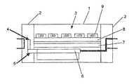
- a lighting deviceincludes a tube and end caps located at two ends of the tube, a lighting assembly arranged in the tube, a driver for the lighting assembly, an antenna and a wireless communication circuit for conducting wireless communication, the antenna being provided in the end cap and the wireless communication circuit being provided in the tube or at least partially provided in the end cap, and one side of the wire communication circuit being connected to the driver and the other side thereof being connected to the antenna. Since the antenna for wireless communication is provided advantageously in the end cap, the space on light engine inside the tube is not occupied as compared with the related art.
- FIG. 2is a schematic diagram of an internal structure of a lighting device according to a specific embodiment of the present disclosure, wherein the lighting device is designed as a tube shape;
Landscapes
- Engineering & Computer Science (AREA)
- General Engineering & Computer Science (AREA)
- Microelectronics & Electronic Packaging (AREA)
- Physics & Mathematics (AREA)
- Optics & Photonics (AREA)
- Computer Networks & Wireless Communication (AREA)
- Arrangement Of Elements, Cooling, Sealing, Or The Like Of Lighting Devices (AREA)
- Non-Portable Lighting Devices Or Systems Thereof (AREA)
- Support Of Aerials (AREA)
- Details Of Aerials (AREA)
Abstract
Description
- 1 tube
- 2 end cap
- 3 lighting assembly
- 4 antenna
- 5 wireless communication circuit
- 6 LED driver
- 7 heat sink
- 8 light engine
Claims (9)
Applications Claiming Priority (4)
| Application Number | Priority Date | Filing Date | Title |
|---|---|---|---|
| CN201110273883.XACN102997080B (en) | 2011-09-15 | 2011-09-15 | A kind of illuminator |
| CN201110273883.X | 2011-09-15 | ||
| CN201110273883 | 2011-09-15 | ||
| PCT/EP2012/065900WO2013037585A1 (en) | 2011-09-15 | 2012-08-14 | Lighting device |
Publications (2)
| Publication Number | Publication Date |
|---|---|
| US20140375204A1 US20140375204A1 (en) | 2014-12-25 |
| US9629224B2true US9629224B2 (en) | 2017-04-18 |
Family
ID=46758731
Family Applications (1)
| Application Number | Title | Priority Date | Filing Date |
|---|---|---|---|
| US14/344,920Expired - Fee RelatedUS9629224B2 (en) | 2011-09-15 | 2012-08-14 | Lighting device |
Country Status (4)
| Country | Link |
|---|---|
| US (1) | US9629224B2 (en) |
| EP (1) | EP2756735B1 (en) |
| CN (1) | CN102997080B (en) |
| WO (1) | WO2013037585A1 (en) |
Cited By (1)
| Publication number | Priority date | Publication date | Assignee | Title |
|---|---|---|---|---|
| US20200320840A1 (en)* | 2008-10-24 | 2020-10-08 | Ilumisys, Inc. | Integration of LED Lighting Control with Emergency Notification Systems |
Families Citing this family (10)
| Publication number | Priority date | Publication date | Assignee | Title |
|---|---|---|---|---|
| DE102013223069A1 (en)* | 2013-11-13 | 2015-05-13 | Osram Opto Semiconductors Gmbh | Optoelectronic component and method for its production |
| US9435521B2 (en)* | 2014-05-21 | 2016-09-06 | Technical Consumer Products, Inc. | Antenna element for a directional lighting fixture |
| CN107208850A (en) | 2014-10-27 | 2017-09-26 | 飞利浦照明控股有限公司 | wireless LED tubular lamp device |
| US10145516B2 (en) | 2016-08-30 | 2018-12-04 | Lecconnect, Llc | LED light tube end cap with self-docking driver comm board |
| EP3580732A4 (en) | 2017-02-08 | 2020-12-09 | The Lockout Co., LLC | Building lockdown system |
| US10512140B2 (en) | 2017-02-26 | 2019-12-17 | LIFI Labs, Inc. | Lighting system |
| CN207471184U (en)* | 2017-08-25 | 2018-06-08 | 深圳佳比泰智能照明股份有限公司 | A kind of intelligence line lamp |
| JP7330560B2 (en)* | 2020-06-23 | 2023-08-22 | アイリスオーヤマ株式会社 | Light-emitting unit and lighting device |
| CN114508743B (en)* | 2022-01-27 | 2023-11-10 | 厦门普为光电科技有限公司 | Lamp cap with hidden antenna and installation method of hidden antenna |
| CN114543054A (en)* | 2022-02-09 | 2022-05-27 | 厦门普为光电科技有限公司 | Lighting device with hidden antenna and manufacturing method thereof |
Citations (34)
| Publication number | Priority date | Publication date | Assignee | Title |
|---|---|---|---|---|
| US20020114155A1 (en)* | 2000-11-24 | 2002-08-22 | Masayuki Katogi | Illumination system and illumination unit |
| US6784620B1 (en)* | 2003-03-10 | 2004-08-31 | Lockheed Martin Corporation | Plasma filter |
| US20050162101A1 (en)* | 2002-11-19 | 2005-07-28 | Denovo Lighting, Llc | Power controls for tube mounted LEDs with ballast |
| US20050281030A1 (en)* | 2002-11-19 | 2005-12-22 | Denovo Lighting, Llc | Power controls with photosensor for tube mounted LEDs with ballast |
| US20070098384A1 (en)* | 2005-08-30 | 2007-05-03 | Nikon Corporation | Camera and exchangeable lens barrel with wireless communication function |
| US7218056B1 (en)* | 2006-03-13 | 2007-05-15 | Ronald Paul Harwood | Lighting device with multiple power sources and multiple modes of operation |
| US7307391B2 (en)* | 2006-02-09 | 2007-12-11 | Led Smart Inc. | LED lighting system |
| CN201127136Y (en) | 2007-08-03 | 2008-10-01 | 王勉行 | Unit control device for large-scale lamp group |
| US20080290814A1 (en)* | 2006-02-07 | 2008-11-27 | Leong Susan J | Power Controls for Tube Mounted Leds With Ballast |
| CN201412698Y (en) | 2009-03-07 | 2010-02-24 | 宁波永望电子科技有限公司 | Ultra-thin LED digital screen lamp box |
| US20100079075A1 (en)* | 2008-09-29 | 2010-04-01 | Won Jin Son | Light Emitting Apparatus |
| US20100103664A1 (en)* | 2008-10-24 | 2010-04-29 | Altair Engineering, Inc. | Lighting including integral communication apparatus |
| US20100106306A1 (en)* | 2008-10-24 | 2010-04-29 | Altair Engineering, Inc. | Integration of led lighting with building controls |
| US20100117558A1 (en)* | 2008-11-11 | 2010-05-13 | Young Hwan Lee | Illumination Apparatus and Driving Method Thereof |
| US20100176724A1 (en)* | 2009-01-09 | 2010-07-15 | Neal Andrew T | LED Tubular Lighting Fixture |
| US20100177532A1 (en)* | 2009-01-15 | 2010-07-15 | Altair Engineering, Inc. | Led lens |
| US20100220469A1 (en)* | 2008-05-23 | 2010-09-02 | Altair Engineering, Inc. | D-shaped cross section l.e.d. based light |
| US20100271802A1 (en) | 2006-03-28 | 2010-10-28 | Recker Michael V | Wireless lighting devices and grid-shifting applications |
| WO2010140136A1 (en) | 2009-06-05 | 2010-12-09 | Koninklijke Philips Electronics N.V. | Lighting device with built-in rf antenna |
| US20120002415A1 (en)* | 2010-06-30 | 2012-01-05 | Nelson Peter K | Ventilation for led lighting |
| US20120008315A1 (en)* | 2010-07-08 | 2012-01-12 | Altair Engineering, Inc. | Independent modules for led fluorescent light tube replacement |
| US20120014108A1 (en)* | 2010-02-25 | 2012-01-19 | B/E Aerospace, Inc. | Led lighting element |
| US20120086345A1 (en)* | 2011-11-20 | 2012-04-12 | Tran Bao Q | Solid state light system with broadband optical communication capability |
| US20120236552A1 (en)* | 2009-11-26 | 2012-09-20 | Werner Leineweber | Linear Lamp |
| US8324817B2 (en)* | 2008-10-24 | 2012-12-04 | Ilumisys, Inc. | Light and light sensor |
| US8376583B2 (en)* | 2010-05-17 | 2013-02-19 | Orion Energy Systems, Inc. | Lighting system with customized intensity and profile |
| US20130050997A1 (en)* | 2011-08-29 | 2013-02-28 | Eric Bretschneider | Lighting unit and methods |
| US8419223B2 (en)* | 2009-04-23 | 2013-04-16 | Billy V. Withers | LED tube to replace fluorescent tube |
| US8444292B2 (en)* | 2008-10-24 | 2013-05-21 | Ilumisys, Inc. | End cap substitute for LED-based tube replacement light |
| US8541958B2 (en)* | 2010-03-26 | 2013-09-24 | Ilumisys, Inc. | LED light with thermoelectric generator |
| US8596813B2 (en)* | 2010-07-12 | 2013-12-03 | Ilumisys, Inc. | Circuit board mount for LED light tube |
| US8807785B2 (en)* | 2008-05-23 | 2014-08-19 | Ilumisys, Inc. | Electric shock resistant L.E.D. based light |
| US8901823B2 (en)* | 2008-10-24 | 2014-12-02 | Ilumisys, Inc. | Light and light sensor |
| US8931933B2 (en)* | 2010-03-03 | 2015-01-13 | Cree, Inc. | LED lamp with active cooling element |
- 2011
- 2011-09-15CNCN201110273883.XApatent/CN102997080B/ennot_activeExpired - Fee Related
- 2012
- 2012-08-14EPEP12753095.4Apatent/EP2756735B1/enactiveActive
- 2012-08-14USUS14/344,920patent/US9629224B2/ennot_activeExpired - Fee Related
- 2012-08-14WOPCT/EP2012/065900patent/WO2013037585A1/enactiveApplication Filing
Patent Citations (34)
| Publication number | Priority date | Publication date | Assignee | Title |
|---|---|---|---|---|
| US20020114155A1 (en)* | 2000-11-24 | 2002-08-22 | Masayuki Katogi | Illumination system and illumination unit |
| US20050162101A1 (en)* | 2002-11-19 | 2005-07-28 | Denovo Lighting, Llc | Power controls for tube mounted LEDs with ballast |
| US20050281030A1 (en)* | 2002-11-19 | 2005-12-22 | Denovo Lighting, Llc | Power controls with photosensor for tube mounted LEDs with ballast |
| US6784620B1 (en)* | 2003-03-10 | 2004-08-31 | Lockheed Martin Corporation | Plasma filter |
| US20070098384A1 (en)* | 2005-08-30 | 2007-05-03 | Nikon Corporation | Camera and exchangeable lens barrel with wireless communication function |
| US20080290814A1 (en)* | 2006-02-07 | 2008-11-27 | Leong Susan J | Power Controls for Tube Mounted Leds With Ballast |
| US7307391B2 (en)* | 2006-02-09 | 2007-12-11 | Led Smart Inc. | LED lighting system |
| US7218056B1 (en)* | 2006-03-13 | 2007-05-15 | Ronald Paul Harwood | Lighting device with multiple power sources and multiple modes of operation |
| US20100271802A1 (en) | 2006-03-28 | 2010-10-28 | Recker Michael V | Wireless lighting devices and grid-shifting applications |
| CN201127136Y (en) | 2007-08-03 | 2008-10-01 | 王勉行 | Unit control device for large-scale lamp group |
| US20100220469A1 (en)* | 2008-05-23 | 2010-09-02 | Altair Engineering, Inc. | D-shaped cross section l.e.d. based light |
| US8807785B2 (en)* | 2008-05-23 | 2014-08-19 | Ilumisys, Inc. | Electric shock resistant L.E.D. based light |
| US20100079075A1 (en)* | 2008-09-29 | 2010-04-01 | Won Jin Son | Light Emitting Apparatus |
| US8901823B2 (en)* | 2008-10-24 | 2014-12-02 | Ilumisys, Inc. | Light and light sensor |
| US20100106306A1 (en)* | 2008-10-24 | 2010-04-29 | Altair Engineering, Inc. | Integration of led lighting with building controls |
| US8324817B2 (en)* | 2008-10-24 | 2012-12-04 | Ilumisys, Inc. | Light and light sensor |
| US8444292B2 (en)* | 2008-10-24 | 2013-05-21 | Ilumisys, Inc. | End cap substitute for LED-based tube replacement light |
| US20100103664A1 (en)* | 2008-10-24 | 2010-04-29 | Altair Engineering, Inc. | Lighting including integral communication apparatus |
| US20100117558A1 (en)* | 2008-11-11 | 2010-05-13 | Young Hwan Lee | Illumination Apparatus and Driving Method Thereof |
| US20100176724A1 (en)* | 2009-01-09 | 2010-07-15 | Neal Andrew T | LED Tubular Lighting Fixture |
| US20100177532A1 (en)* | 2009-01-15 | 2010-07-15 | Altair Engineering, Inc. | Led lens |
| CN201412698Y (en) | 2009-03-07 | 2010-02-24 | 宁波永望电子科技有限公司 | Ultra-thin LED digital screen lamp box |
| US8419223B2 (en)* | 2009-04-23 | 2013-04-16 | Billy V. Withers | LED tube to replace fluorescent tube |
| WO2010140136A1 (en) | 2009-06-05 | 2010-12-09 | Koninklijke Philips Electronics N.V. | Lighting device with built-in rf antenna |
| US20120236552A1 (en)* | 2009-11-26 | 2012-09-20 | Werner Leineweber | Linear Lamp |
| US20120014108A1 (en)* | 2010-02-25 | 2012-01-19 | B/E Aerospace, Inc. | Led lighting element |
| US8931933B2 (en)* | 2010-03-03 | 2015-01-13 | Cree, Inc. | LED lamp with active cooling element |
| US8541958B2 (en)* | 2010-03-26 | 2013-09-24 | Ilumisys, Inc. | LED light with thermoelectric generator |
| US8376583B2 (en)* | 2010-05-17 | 2013-02-19 | Orion Energy Systems, Inc. | Lighting system with customized intensity and profile |
| US20120002415A1 (en)* | 2010-06-30 | 2012-01-05 | Nelson Peter K | Ventilation for led lighting |
| US20120008315A1 (en)* | 2010-07-08 | 2012-01-12 | Altair Engineering, Inc. | Independent modules for led fluorescent light tube replacement |
| US8596813B2 (en)* | 2010-07-12 | 2013-12-03 | Ilumisys, Inc. | Circuit board mount for LED light tube |
| US20130050997A1 (en)* | 2011-08-29 | 2013-02-28 | Eric Bretschneider | Lighting unit and methods |
| US20120086345A1 (en)* | 2011-11-20 | 2012-04-12 | Tran Bao Q | Solid state light system with broadband optical communication capability |
Non-Patent Citations (2)
| Title |
|---|
| Chinese Office Action based on Application No. 201110273883.X(5 Pages and 5 pages of English translation) dated Jul. 14, 2015. |
| International Search Report issued in the corresponding PCT application No. PCT/EP2012/065900, dated Oct. 18, 2012. |
Cited By (1)
| Publication number | Priority date | Publication date | Assignee | Title |
|---|---|---|---|---|
| US20200320840A1 (en)* | 2008-10-24 | 2020-10-08 | Ilumisys, Inc. | Integration of LED Lighting Control with Emergency Notification Systems |
Also Published As
| Publication number | Publication date |
|---|---|
| US20140375204A1 (en) | 2014-12-25 |
| CN102997080B (en) | 2016-09-07 |
| WO2013037585A1 (en) | 2013-03-21 |
| EP2756735A1 (en) | 2014-07-23 |
| EP2756735B1 (en) | 2015-11-18 |
| CN102997080A (en) | 2013-03-27 |
Similar Documents
| Publication | Publication Date | Title |
|---|---|---|
| US9629224B2 (en) | Lighting device | |
| US8604679B2 (en) | LED light source lamp having drive circuit arranged in outer periphery of led light source | |
| US20170234519A1 (en) | Led lamp unit | |
| JP2012181992A (en) | Lighting fixture | |
| WO2011078485A3 (en) | Led lighting device | |
| JP3179599U (en) | Separate drive circuit structure for straight tube type LED lamp | |
| KR101216080B1 (en) | Lighting apparatus | |
| US8651728B2 (en) | Lighting master and lighting device | |
| TW201002977A (en) | LED lamp | |
| EP3051202B1 (en) | Multi-directional led lamp | |
| EP2611267A3 (en) | Lamp structure capable of switching light-emitting mode | |
| EP2786641B1 (en) | Master illuminating device, illuminating device and illumination control system | |
| KR20170095417A (en) | Lighting device and electronic device including the same | |
| CN203718668U (en) | LED (light emitting diode) lighting device with built-in ultraviolet lamp | |
| CN101418914B (en) | Portable lamp with light-emitting diodes | |
| US8334641B2 (en) | Lighting device | |
| CN206361446U (en) | Integrated fluorescent tube | |
| CN205979662U (en) | Easily install driven filament lamp | |
| JP6288955B2 (en) | Lighting circuit unit, illumination lamp, and illumination device | |
| US20140355288A1 (en) | Lamp and vehicle comprising the same | |
| JP6963736B2 (en) | lighting equipment | |
| WO2012165786A3 (en) | Light emitting diode lamp | |
| CN208397808U (en) | A kind of electronic device | |
| CN202813301U (en) | Radiating mechanism for LED (Light-Emitting Diode) point light source ceiling lamp | |
| CN202629794U (en) | Light-emitting diode (LED) lamp special for elevator |
Legal Events
| Date | Code | Title | Description |
|---|---|---|---|
| AS | Assignment | Owner name:OSRAM CHINA LIGHTING LTD., CHINA Free format text:ASSIGNMENT OF ASSIGNORS INTEREST;ASSIGNORS:DAI, XUEWEI;LIN, AIMIN;TJACO, MIDDEL;AND OTHERS;SIGNING DATES FROM 20130328 TO 20140401;REEL/FRAME:032891/0479 Owner name:OSRAM GMBH, GERMANY Free format text:ASSIGNMENT OF ASSIGNORS INTEREST;ASSIGNOR:OSRAM CHINA LIGHTING LTD.;REEL/FRAME:032891/0484 Effective date:20140423 | |
| STCF | Information on status: patent grant | Free format text:PATENTED CASE | |
| AS | Assignment | Owner name:SITECO GMBH, GERMANY Free format text:ASSIGNMENT OF ASSIGNORS INTEREST;ASSIGNOR:OSRAM GMBH;REEL/FRAME:053498/0005 Effective date:20191204 | |
| FEPP | Fee payment procedure | Free format text:MAINTENANCE FEE REMINDER MAILED (ORIGINAL EVENT CODE: REM.); ENTITY STATUS OF PATENT OWNER: LARGE ENTITY | |
| LAPS | Lapse for failure to pay maintenance fees | Free format text:PATENT EXPIRED FOR FAILURE TO PAY MAINTENANCE FEES (ORIGINAL EVENT CODE: EXP.); ENTITY STATUS OF PATENT OWNER: LARGE ENTITY | |
| STCH | Information on status: patent discontinuation | Free format text:PATENT EXPIRED DUE TO NONPAYMENT OF MAINTENANCE FEES UNDER 37 CFR 1.362 | |
| FP | Lapsed due to failure to pay maintenance fee | Effective date:20210418 |