US9627795B2 - Electrical connecting assemblies, and related methods - Google Patents
Electrical connecting assemblies, and related methodsDownload PDFInfo
- Publication number
- US9627795B2 US9627795B2US14/947,755US201514947755AUS9627795B2US 9627795 B2US9627795 B2US 9627795B2US 201514947755 AUS201514947755 AUS 201514947755AUS 9627795 B2US9627795 B2US 9627795B2
- Authority
- US
- United States
- Prior art keywords
- connector
- retainer
- assembly
- opening
- wires
- Prior art date
- Legal status (The legal status is an assumption and is not a legal conclusion. Google has not performed a legal analysis and makes no representation as to the accuracy of the status listed.)
- Active
Links
Images


Classifications
- H—ELECTRICITY
- H01—ELECTRIC ELEMENTS
- H01R—ELECTRICALLY-CONDUCTIVE CONNECTIONS; STRUCTURAL ASSOCIATIONS OF A PLURALITY OF MUTUALLY-INSULATED ELECTRICAL CONNECTING ELEMENTS; COUPLING DEVICES; CURRENT COLLECTORS
- H01R13/00—Details of coupling devices of the kinds covered by groups H01R12/70 or H01R24/00 - H01R33/00
- H01R13/46—Bases; Cases
- H01R13/502—Bases; Cases composed of different pieces
- H01R13/506—Bases; Cases composed of different pieces assembled by snap action of the parts
- H—ELECTRICITY
- H01—ELECTRIC ELEMENTS
- H01R—ELECTRICALLY-CONDUCTIVE CONNECTIONS; STRUCTURAL ASSOCIATIONS OF A PLURALITY OF MUTUALLY-INSULATED ELECTRICAL CONNECTING ELEMENTS; COUPLING DEVICES; CURRENT COLLECTORS
- H01R13/00—Details of coupling devices of the kinds covered by groups H01R12/70 or H01R24/00 - H01R33/00
- H01R13/46—Bases; Cases
- H01R13/52—Dustproof, splashproof, drip-proof, waterproof, or flameproof cases
- H01R13/5216—Dustproof, splashproof, drip-proof, waterproof, or flameproof cases characterised by the sealing material, e.g. gels or resins
- H—ELECTRICITY
- H01—ELECTRIC ELEMENTS
- H01R—ELECTRICALLY-CONDUCTIVE CONNECTIONS; STRUCTURAL ASSOCIATIONS OF A PLURALITY OF MUTUALLY-INSULATED ELECTRICAL CONNECTING ELEMENTS; COUPLING DEVICES; CURRENT COLLECTORS
- H01R4/00—Electrically-conductive connections between two or more conductive members in direct contact, i.e. touching one another; Means for effecting or maintaining such contact; Electrically-conductive connections having two or more spaced connecting locations for conductors and using contact members penetrating insulation
- H01R4/22—End caps, i.e. of insulating or conductive material for covering or maintaining connections between wires entering the cap from the same end
Definitions
- the present disclosuregenerally relates to electrical connecting assemblies that can be used, for example, to electrically connect wires, and methods related thereto.
- Electrical connectorsare often used for connecting various electrical components of electrical equipment or systems.
- lawn sprinkler systems and landscape lighting systemsinclude a plurality of electrical components that are typically connected using electrical connectors.
- Exemplary embodiments of the present disclosuregenerally relate to electrical connecting assemblies.
- such an assemblygenerally includes a body configured to receive a connector therein for electrically connecting at least two wires, and a retainer configured to releasably couple to the body.
- the retainerhas at least one arm configured to extend into the body, when the retainer is coupled to the body, and inhibit movement of the connector out of the body after the connector is received in the body.
- an assembly for electrically connecting wiresgenerally includes a connector configured to electrically connect the wires, a body defining an opening for receiving the connector into the body when the connector is electrically connecting the wires, and a retainer configured to couple to the body adjacent the opening of the body.
- the retainerhas at least one arm configured to extend through the opening of the body, when the retainer is coupled to the body, to inhibit movement of the connector out of the body after the connector is received in the body
- Exemplary embodiments of the present disclosurealso generally relate to methods of making an electrical connection using an electrical connecting assembly.
- such a methodgenerally includes inserting at least two electrical wires into an opening of a connector of the assembly, moving the connector through an opening of a retainer of the assembly and into a body of the assembly, and coupling the retainer of the assembly to the body of the assembly, such that an arm of the retainer is positioned within the body for inhibiting movement of the connector out of the body.
- FIG. 1is an exploded perspective view of an exemplary embodiment of an assembly according to the present disclosure for use in electrically connecting at least two wires;
- FIG. 2is a top view of a connector of the assembly of FIG. 1 ;
- FIG. 3is another exploded perspective view of the assembly of FIG. 1 , with the connector removed;
- FIG. 4is a perspective view of the assembly of FIG. 3 , with a retainer of the assembly shown in a first position partially inserted into a body of the assembly;
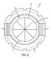
- FIG. 5is a top view of the assembly of FIG. 4 ;
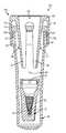
- FIG. 6is a sectional view of the assembly of FIG. 1 , with the connector above the retainer and the body and with the retainer shown in the first position partially inserted into the body of the assembly;
- FIG. 7is the sectional view of FIG. 6 , with the connector inserted into the body of the assembly.
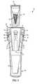
- FIG. 8is the sectional view of FIG. 7 , with the retainer moved from the first position to a second position fully inserted into the body.
- the present disclosureis generally directed toward electrical connecting assemblies that can be used, for example, for electrically connecting wires.
- the electrical connecting assembliesgenerally include a body (e.g., a base, a receptacle, a tube, etc.) configured to receive a connector (e.g., a twist-on wire connector, etc.) therein for electrically connecting at least two wires, and a retainer (e.g., a plunger lid, a cap, a cover, etc.) configured to releasably (e.g., snap-fit, etc.) couple to the body.
- a bodye.g., a base, a receptacle, a tube, etc.
- a connectore.g., a twist-on wire connector, etc.
- a retainere.g., a plunger lid, a cap, a cover, etc.
- the retainerhas at least one arm (e.g., at least one member, at least one protrusion, etc.) configured to extend into the body when the retainer is coupled to the body, and inhibit movement of the connector out of the body and after the connector is received in the body.
- at least one arme.g., at least one member, at least one protrusion, etc.
- the assembliesinclude the connector.
- the connectordefines an opening for receiving the at least two wires into the connector for electrically connecting the wires (e.g., via electrical contact of exposed ends of the wires, etc.).
- the connectormay include a metallic coil for electrically connecting the wires.
- the connectormay include a plurality of fingers (e.g., resilient fingers, tabs, etc.) adjacent the opening for flexibly engaging the wires when the wires are received through the opening.
- the fingersmay direct the wires toward a center of the opening of the connector, provide strain relief to the wires, assist in holding the wires in place in the connector, assist in preventing water and/or other substances from entering the connector, etc.
- the assembliesinclude sealant (e.g., grease, etc.) disposed within the body of the assemblies and/or the connector.
- sealante.g., grease, etc.
- the sealantmay be disposed in both the connector and the body to inhibit water from entering the connector and interfering with the electrical connection between the wires.
- at least one arm of the retainermay be configured to direct the sealant toward an opening of the connector (e.g., an opening through which the at least two wires are received into the connector, etc.), after the connector is received in the body and when the retainer is coupled to the body.
- the at least one arm of the retainermay assist in directing sealant against the opening of the connector to provide further inhibition of water from entering the connector and interfering with the electrical connection between the wires (e.g., if water inadvertently enters the body, etc.).
- the body of the assembliesdefines an opening configured to permit the connector to be inserted through the opening and into the body, with the at least one arm of the retainer configured to be positioned in the body through the opening and with the retainer configured to releasably couple to the body adjacent the opening of the body.
- the openingmay be at one end of the body and the retainer may snap-fit to that end of the body.
- the retainermay also define an opening configured to generally align with the opening of the body when the at least one arm of the retainer is disposed at least partially in the body, with the aligned openings configured to receive the connector therethrough for receiving the connector into the body.
- the connectormay be received into the body by inserting the connector through openings in both the retainer and the body, when the at least one arm of the retainer is already disposed at least partially in the body, and the retainer can then be coupled to the body.
- the connectorcan be received into the body of the assemblies before the at least one arm of the retainer is disposed at least partially in the body. Further, in some embodiments, it may be possible to insert the connector into the body even after the retainer has already been coupled to the body.
- the retainer of the assembliesincludes at least two arms, which are configured to resiliently move generally away from each other to permit the connector to pass between the at least two arms when receiving the connector in the body, and then to move generally toward each other after the connector is received in the body.
- the at least two armsmay be pushed apart by the connector, while the at least two arms are located at least partially in the body, as the connector is inserted through an opening in the retainer. Once the connector moves past the at least two arms, the arms may move back toward each other, thereby inhibiting the connector from being removed from the body (e.g., by contacting the top of the connector and securing it in the body, etc.).
- this movement of the at least two arms back towards each otheralso directs sealant (when the sealant is present in the body) toward an upper opening of the connector (e.g., an opening through which the at least two wires are received into the connector, etc.).
- the retainer of the assembliesincludes a plurality of fingers adjacent an upper opening of the retainer for flexibly engaging the at least two wires electrically connected by the connector, when the connector is received in the body.
- the fingersmay orient the wires towards the center of the retainer opening, provide strain relief to the wires, assist in holding the wires in place in the body, inhibit water and/or other substances from entering the body, etc.
- the bodyalso includes a lip, and the retainer includes a clasp configured to engage the lip for releasably coupling the retainer to the body.
- the electrical connecting assemblies of the present disclosuremay facilitate electrical connection of wires while also inhibiting water and/or other substances from interfering with the electrical connection of the wires, thereby providing for electrical connection of the wires in outdoor, underground, etc. environments that may otherwise expose the electrical connection to harmful elements (e.g., in connection with lawn sprinkler systems, landscape lighting systems, etc.) etc.
- electrical connecting assemblies of the present disclosurecan include one or more of the above described aspects/features in any desired combination, and can further include any of the other features described herein as desired.
- FIGS. 1-8illustrate an exemplary embodiment of an electrical connecting assembly 100 , and components thereof, having one or more aspects of the present disclosure.
- the assembly 100can be used to electrically connect at least two wires (not shown), and can be used to protect an electrical connection of the wires from harmful elements (e.g., water, dirt, etc.).
- the illustrated assembly 100generally includes a connector 102 , a body 104 , and a retainer 106 .
- the connector 102is configured to electrically connect wires (e.g., at least two wires, etc.) inserted into the connector 102 .
- the body 104is then configured to receive the connector 102 , and the electrically connected wires, therein.
- the retainer 106is configured to releasably couple to the body 104 to help secure the connector 102 (and the wires electrically connected by the connector 102 ) in the body 104 .
- the connector 102 of the illustrated assembly 100generally includes a twist-on type wire connector for connecting the wires inserted therein.
- the connector 102includes a metallic coil 108 disposed therein to electrically connect the wires ( FIG. 5 ).
- FIG. 5it should be appreciated that other types of connectors may be used in other embodiments, for example, connectors other than twist-on type wire connectors, etc.
- the connector 102also includes a plurality of fingers 110 adjacent an upper opening 112 of the connector 102 (where the wires are inserted into the connector 102 to facilitate the electrical connection) ( FIG. 2 ).
- the fingers 110are resiliently flexible and are configured to engage the wires received through the connector opening 112 .
- the fingers 110operate, generally, to direct the wires toward a center of the opening 112 , to provide strain relief to the wires in the connector 102 , to assist in holding the wires in place in the connector 102 , to assist in preventing water and/or other substances/debris from entering the connector 102 , etc.
- the fingers 110are slightly spaced apart from each other and an opening is provided toward tips of the fingers.
- the connector 102can include any suitable number of fingers 110 , which may or may not cover substantially the entire opening 112 of the connector 102 .
- the connector 102 and/or the fingers 110may comprise any suitable similar or different material (e.g., plastic, rubber, etc.).
- assembliesmay include different connectors (e.g., different from connector 102 , etc.) and/or connectors with other suitable electrical connection components.
- the connector 102 of the assembly 100also includes an insulating material (or sealant) therein to help coat, surround, etc. the wires (e.g., the bare end portions of the wires, etc.) when the wires are inserted into the connector 102 .
- an insulating materialmay be used including, for example, a moisture resistant encapsulant or gel that is viscous or non-viscous, a hardening or non-hardening epoxy or potting compound, etc.
- the insulating materialmay have a sufficient viscosity so that it will not flow out of the connector 102 , but at the same time will move with the wires and flow around them as they are connected in the connector 102 (e.g., to provide a seal around the connected wires in the connector 102 to inhibit water and/or other substances/debris from interfering with the electrical connection of the wires, etc.).
- the body 104 of the assembly 100includes a generally closed lower end portion and a generally open upper end portion.
- An opening 116is defined at the upper end portion of the body 104 , with an enlarged rim 118 extending partially around the opening 116 .
- guides 120are defined in the rim 118 , on generally opposite sides of the body 104 .
- the body 104may be formed from any suitable material including, for example, plastic, rubber, etc.
- assembliesmay include bodies having different shapes and/or configurations than illustrated herein.
- the body 104 of the assembly 100can receive various different sizes of connectors (e.g., the size of the connector 102 does not need to match the size of the body 104 , etc.). As such, the body 104 is configured to allow connectors of multiple different sizes to be inserted into and retained within the body 104 .
- the retainer 106 of the assembly 100includes first and second arms 122 , 124 , and first and second clasps 126 , 128 for use in coupling the retainer 106 to the body 104 .
- the arms 122 , 124are resiliently coupled to a neck 130 of the retainer 106 , and are separated by a gap (or spacing). As such, the arms 122 , 124 can each independently flex, relative to the neck 130 , toward and away from each other (as will be described more hereinafter). It should be appreciated that the gap between the arms 122 , 124 may have any suitable shape and/or size within the scope of the present disclosure.
- the clasps 126 , 128 of the retainer 106are also resiliently coupled to the neck 130 , and can flex in similar fashion to the arms 122 , 124 .
- assembliesmay include retainers having different numbers of arms and/or different numbers of clasps (e.g., one, three, four, etc.).
- assembliesmay include retainers with engagement components other than clasps (e.g., screw threads, friction fit devices, etc.) for use in coupling the retainers to bodies of the assemblies.
- the illustrated retainer 106also includes a plurality of fingers 134 adjacent an upper opening 136 of the retainer 106 .
- the fingers 134are resiliently flexible and are configured to engage the wires received through the opening 136 , when the connector 102 is positioned in the body 104 of the assembly 100 (as will be described more hereinafter).
- the fingers 134operate, generally, to direct the wires toward a center of the opening 136 , to provide strain relief to the wires in the assembly 100 , to assist in holding the wires in place in the assembly 100 , to assist in preventing water and/or other substances/debris from entering the assembly 100 , etc.
- the fingers 134may be formed integrally with the retainer 106 , or the fingers 134 may be formed as a structure separate from the retainer 106 and coupled thereto as desired (e.g., snap-fit to the retainer 106 at opening 136 via circumferential tabs on a base structure supporting the fingers 134 , where the tabs are received in corresponding openings within the neck 130 of the retainer 106 ; etc.). It should be appreciated that a similar construction may also be used for the fingers 110 of the connector 102 .
- the retainer 106(and/or the fingers 134 thereof) may also be formed from any suitable material including, for example, plastic, rubber, etc.
- assembliesmay include retainers having different shapes and/or configurations than illustrated herein.
- the retainer 106is initially positioned partially within the body 104 . And, the connector 102 , with the wires electrically connected therein, is then inserted into the body 104 through the retainer 106 . However, it should be appreciated that in other embodiments, the connector 102 (with the wires electrically connected therein) can be initially inserted into the body 104 (before the retainer 106 ), and the retainer 106 then positioned within the body 104 generally over the connector 102 .
- the retainer 106is initially positioned in the body 104 in a first position (e.g., a staging position, etc.), with the arms 122 , 124 of the retainer 106 initially located (or positioned) within a channel 138 of the body 104 , through the body's upper opening 116 , and the clasps 126 , 128 of the retainer 106 engaging the body 104 at the guides 120 . End portions 126 a , 128 a of each of the clasps 126 , 128 are located in corresponding detents 140 in upper portions of the guides 120 of the body 104 to help hold the retainer 106 in the first position.
- the upper opening 136 of the retainer 106generally aligns with the upper opening 116 of the body 104 .
- the connector 102(and the wires electrically connected therein) is then inserted into the body 104 through the aligned openings 136 , 116 of the retainer 106 and the body 104 (with the retainer 106 still in the first position).
- the arms 122 , 124 of the retainer 106are spaced apart by a first distance (in a normal, un-flexed, position as shown in FIG. 6 ).
- the arms 122 , 124When receiving the connector 102 into the body 104 , and through the retainer 106 , the arms 122 , 124 are pushed apart by the connector 102 (e.g., the arms 122 , 124 resiliently flex away from each other, etc.) to provide room for the connector 102 to move between the arms 122 , 124 , through the retainer 106 , and into a lower receptacle 142 of the body's channel 138 .
- the arms 122 , 124move back to the normal position (e.g., the arms 122 , 124 move back toward each other, etc.), into a location generally over the connector 102 .
- the retainer 106is moved (e.g., pressed, etc.) toward (or generally into, etc.) the body 104 (e.g., by a user, etc.), to a second position (i.e., the retainer 106 is moved from the first position in FIG. 7 to the second position in FIG. 8 ).
- the end portions 126 a , 128 a of the clasps 126 , 128are pushed (e.g., cammed, etc.) out of the detents 140 , and the clasps 126 , 128 resiliently move, flex, etc. generally outward (e.g., away from each other, etc.).
- the clasps 126 , 128then slide along the guides 120 (in a direction toward the closed end of the body 104 ) until the end portions 126 a , 128 a of the clasps 126 , 128 reach lips 144 of the guides 120 , at which time the end portions 126 a , 128 a are pushed under the lips 144 by the resilient nature of the clasps 126 , 128 .
- the neck 130 of the retainer 106generally engages (and seals against, etc.) the rim 118 of the body 104 .
- the arms 122 , 124 of the retainer 106move within the body's channel 138 toward the connector 102 (and, in some embodiments, into engagement with an upper portion of the connector 102 ) for inhibiting movement of the connector 102 out of the lower receptacle 142 (e.g., back through the body 104 and the retainer 106 of the assembly 100 , etc.).
- the retainer 106is snap-fit, releasably coupled, etc. to the body 104 of the assembly 100 (e.g., via the clasps 126 , 128 , etc.).
- the retainer 106can be released from the body 104 , if desired (e.g., to remove the connector 102 from the body 104 , etc.), by moving the end portions 126 a , 128 a of the clasps 126 , 128 out of the lips 144 and sliding the retainer 106 off the body 104 .
- the retainer 106may include additional seals (e.g., on the arms 122 , 124 , on the neck 130 , etc.) that contact, for example, the body 104 , etc. when in the second position to further help inhibit water, debris, other substances etc. from entering the assembly 100 , after the retainer 106 is coupled to the body 104 .
- additional sealse.g., on the arms 122 , 124 , on the neck 130 , etc.
- the body 104includes an insulating material (or sealant) therein (e.g., in the channel 138 , etc.) to help coat, surround, etc. the connector 102 when received in the body 104 (and the bare end portions of the wires therein, etc.).
- an insulating materialor sealant
- any suitable insulating materialmay be used including, for example, a moisture resistant encapsulant or gel that is viscous or non-viscous, a hardening or non-hardening epoxy or potting compound, etc.
- the insulating materialmay have a sufficient viscosity so that it will not flow out of the body 104 of the assembly 100 , but at the same time will move with the connector 102 and flow around it as it moves into the body 104 (e.g., to provide a seal around the connected wires to inhibit water and/or other substances from interfering with the electrical connection of the wires, etc.).
- the connector 102when the connector 102 is received in the body 104 of the assembly 100 (and moves though the body's channel 138 ), it displaces the insulating material therein and may leave a void generally above the connector 102 (e.g., along the path of the connector's movement through the body's channel 138 , etc.).
- the arms 122 , 124 of the retainer 106operate to move, direct, etc.
- the arms 122 , 124 of the retainer 106are initially pushed apart by the connector 102 .
- the arms 122 , 124move back to the normal position (generally over the connector 102 ). During this movement, the arms 122 , 124 also operate to pull displaced insulating material back and over the connector 102 . Then, when the retainer 106 is moved from the first position to the second position, the arms 122 , 124 push this insulating material down and onto the connector 102 , generally toward, over, etc. the opening 112 of the connector 102 , etc. to help implement the seal. Further, rings 146 on the arms of the retainer 106 may further help move the insulating material toward the opening 112 of the connector 102 .
- These featuresmay reduce the need to agitate the insulating material in the body 104 , for example, by moving the connector 102 up and down in the insulating material (as done in previous assemblies), which may lead to formation of smaller air bubbles, other voids, or disconnection of the wires in the connector 102 .
- the connector 102may only be capable of being inserted through aligned upper openings 136 , 116 of the retainer 106 and the body 104 when the retainer 106 is in the first position ( FIG. 6 ), and not when the retainer 106 is in the second position ( FIG. 8 ).
- the arms 122 , 124 of the retainer 106are permitted to expand, separate, flex, etc. enough to allow the connector 102 to pass by the arms 122 , 124 and through the retainer 106 (and into the lower receptacle 142 of the body's channel 138 ).
- the arms 122 , 124are prevented from expanding, separating, flexing, etc. and allowing the connector 102 to pass through them (e.g., because the arms 122 , 124 contact a narrower width of the body 104 when the retainer 106 is in the second position, etc.).
- the connector 102may be capable of being inserted through aligned upper openings 136 , 116 of the retainer 106 and the body 104 when the retainer 106 is in the first position ( FIG. 6 ) and when the retainer 106 is in the second position ( FIG. 8 ).
- the resilient nature of the arms 122 , 124 of the retainer 106(generally biasing, and holding, the arms 122 , 124 in the normal, un-flexed, position) then operates to locate the arms 122 , 124 generally over the retainer 106 and inhibit movement of the retainer 106 out of the lower receptacle 142 .
- the first positon of the retainer 106may be removed or eliminated.
- the retainer 106is partially coupled to the body 104 (in the first position) before the connector 102 (with wires pre-inserted) is received into the body 104 (through the aligned openings 136 , 116 of the retainer 106 and the body 104 ), it should again be appreciated that in some implementations the connector 102 may be inserted into the body 104 prior to positioning the retainer 106 in the body 104 . Further, in some implementations, the wires may be inserted into the connector 102 after the connector 102 is received in the body 104 .
- the wiresmay be inserted into the connector 102 and the connector 102 then inserted through the retainer 106 (before the retainer 106 is positioned in the body 104 ). And, the connector 102 and retainer 106 may then be inserted into the body 104 (this may require keeping the retainer 106 and body 104 separate).
- the assembly 100 of the present disclosuremay allow for more efficient and reliable electrical connection and ease of use by a user.
- the usercan simply insert the wires into the connector 102 , then insert the connector 102 (with the wires connected therein) through a pre-assembled arrangement of the retainer 106 and the body 104 (e.g., with the retainer 106 already positioned, out of the packaging, in the body 104 in the first position, etc.).
- the assembly 100may be received by a user in two parts.
- the first partmay include the body 104 , filled with a sealant (e.g., grease, etc.), and the retainer 106 coupled to the body 104 as a complete unit.
- a sealante.g., grease, etc.
- the second partmay then include the connector 102 (e.g., a twist-on wire connector, etc.), which may or may not be filled with sealant.
- a splicee.g., a connection, coupling, etc.
- the connector 102is then plunged into the sealant in the body 104 .
- the retainer 106is then pressed into the second, locking position, which (as previously described) directs the sealant (e.g., folds the sealant, displaces the sealant, directs the sealant, etc.) over the top of the wire connector 102 to close any channel that may have formed when plunging the connector 102 into the sealant in the body 104 , thereby inhibiting entry of water or other debris.
- Thisalso helps secure the connector 102 in the body 104 adjacent the bottom of the body 104 and generally creates a wire restraint.
- first, second, third, etc.may be used herein to describe various elements, components, regions, layers and/or sections, these elements, components, regions, layers and/or sections should not be limited by these terms. These terms may be only used to distinguish one element, component, region, layer or section from another region, layer or section. Terms such as “first,” “second,” and other numerical terms when used herein do not imply a sequence or order unless clearly indicated by the context. Thus, a first element, component, region, layer or section discussed below could be termed a second element, component, region, layer or section without departing from the teachings of the exemplary embodiments.
- Spatially relative termssuch as “inner,” “outer,” “beneath,” “below,” “lower,” “above,” “upper,” “left,”, “right” and the like, may be used herein for ease of description to describe one element or feature's relationship to another element(s) or feature(s) as illustrated in the figures.
- Spatially relative termsmay be intended to encompass different orientations of the device in use or operation in addition to the orientation depicted in the figures. For example, if the device in the figures is turned over, elements described as “below” or “beneath” other elements or features would then be oriented “above” the other elements or features.
- the example term “below”can encompass both an orientation of above and below.
- the devicemay be otherwise oriented (rotated 90 degrees or at other orientations) and the spatially relative descriptors used herein interpreted accordingly.
Landscapes
- Chemical & Material Sciences (AREA)
- Dispersion Chemistry (AREA)
- Connector Housings Or Holding Contact Members (AREA)
- Engineering & Computer Science (AREA)
- Manufacturing & Machinery (AREA)
Abstract
Description
Claims (21)
Priority Applications (2)
| Application Number | Priority Date | Filing Date | Title |
|---|---|---|---|
| US14/947,755US9627795B2 (en) | 2014-11-21 | 2015-11-20 | Electrical connecting assemblies, and related methods |
| US15/420,682US20170141508A1 (en) | 2014-11-21 | 2017-01-31 | Electrical connecting assemblies, and related methods |
Applications Claiming Priority (2)
| Application Number | Priority Date | Filing Date | Title |
|---|---|---|---|
| US201462083049P | 2014-11-21 | 2014-11-21 | |
| US14/947,755US9627795B2 (en) | 2014-11-21 | 2015-11-20 | Electrical connecting assemblies, and related methods |
Related Child Applications (1)
| Application Number | Title | Priority Date | Filing Date |
|---|---|---|---|
| US15/420,682Continuation-In-PartUS20170141508A1 (en) | 2014-11-21 | 2017-01-31 | Electrical connecting assemblies, and related methods |
Publications (2)
| Publication Number | Publication Date |
|---|---|
| US20160149336A1 US20160149336A1 (en) | 2016-05-26 |
| US9627795B2true US9627795B2 (en) | 2017-04-18 |
Family
ID=56011145
Family Applications (1)
| Application Number | Title | Priority Date | Filing Date |
|---|---|---|---|
| US14/947,755ActiveUS9627795B2 (en) | 2014-11-21 | 2015-11-20 | Electrical connecting assemblies, and related methods |
Country Status (4)
| Country | Link |
|---|---|
| US (1) | US9627795B2 (en) |
| EP (1) | EP3221930A4 (en) |
| AU (1) | AU2015349729A1 (en) |
| WO (1) | WO2016081870A1 (en) |
Cited By (1)
| Publication number | Priority date | Publication date | Assignee | Title |
|---|---|---|---|---|
| US11196191B1 (en)* | 2020-10-23 | 2021-12-07 | Taylor Hardin | Electrical connector with cure-in-place resin |
Families Citing this family (6)
| Publication number | Priority date | Publication date | Assignee | Title |
|---|---|---|---|---|
| AU2015349729A1 (en)* | 2014-11-21 | 2017-06-08 | Duane K. Smith | Electrical connecting assemblies, and related methods |
| JP6534370B2 (en)* | 2016-08-29 | 2019-06-26 | 矢崎総業株式会社 | Pin terminal and connector |
| JP6872965B2 (en)* | 2017-05-02 | 2021-05-19 | 株式会社フジクラ | Electrical connector |
| US11450985B2 (en)* | 2020-08-13 | 2022-09-20 | Aptiv Limited Technologies | Connector with integrated seal retainer and secondary terminal lock |
| DE102022214360A1 (en)* | 2022-12-23 | 2024-07-04 | Technische Universität Dresden, Körperschaft des öffentlichen Rechts | Temporary closure element for exposed electrical conductors of a cable enclosed by electrical insulation |
| US20250202162A1 (en)* | 2023-12-19 | 2025-06-19 | Ideal Industries, Inc. | Electrical connector with rotational snap-fit and swappable contact retainer |
Citations (103)
| Publication number | Priority date | Publication date | Assignee | Title |
|---|---|---|---|---|
| US454181A (en) | 1891-06-16 | Connector for electric wires | ||
| US2589368A (en)* | 1947-06-20 | 1952-03-18 | Thomas & Betts Corp | Pigtail electric connector |
| US2701273A (en)* | 1951-08-08 | 1955-02-01 | Thomas & Betts Corp | Insulating cap for pigtail connectors |
| US2748186A (en)* | 1954-12-20 | 1956-05-29 | Thomas & Betts Corp | Two-piece pigtail connector |
| US2792444A (en)* | 1952-11-17 | 1957-05-14 | Thomas & Betts Corp | Pigtail connector |
| US2823249A (en)* | 1954-12-09 | 1958-02-11 | Thomas & Betts Corp | Snap-on pigtail connector |
| US2870239A (en)* | 1955-02-14 | 1959-01-20 | Buchanan Electrical Prod Corp | Electrical connector |
| US3132202A (en)* | 1962-01-22 | 1964-05-05 | Vaco Products Co | Closed end electrical connector |
| US3165575A (en) | 1962-10-04 | 1965-01-12 | Thomas & Betts Corp | Insulated splicer with end seals |
| US3350499A (en)* | 1966-09-27 | 1967-10-31 | Ideal Ind | Insulated connector |
| US3388367A (en) | 1966-06-20 | 1968-06-11 | Hughes Aircraft Co | Electrical connector for either flat or round conductors |
| US3483310A (en)* | 1968-04-23 | 1969-12-09 | Ideal Ind | Connector insulator |
| US3558800A (en)* | 1970-02-03 | 1971-01-26 | Benedict L Wallis | Sealing pigtail connector construction |
| US3597528A (en)* | 1969-10-27 | 1971-08-03 | Plastic Irrigation Products Co | Electrical connector for insulating an electrical wire joint |
| US3757031A (en) | 1972-05-02 | 1973-09-04 | Thomas & Betts Corp | The like selectively closable protective enclosure for electrical splices and |
| US3864013A (en) | 1973-09-19 | 1975-02-04 | Thomas & Betts Corp | Pre-insulated connector for electrical conductors |
| US3875324A (en)* | 1973-05-31 | 1975-04-01 | Amerace Corp | Wire connector |
| US3902005A (en)* | 1974-03-04 | 1975-08-26 | Ite Imperial Corp | Screw-on electrical connector |
| US4112251A (en)* | 1971-07-14 | 1978-09-05 | Ideal Industrie, Inc. | Screw-on wire connector and method of making it |
| US4125310A (en) | 1975-12-01 | 1978-11-14 | Hughes Aircraft Co | Electrical connector assembly utilizing wafers for connecting electrical cables |
| US4227040A (en)* | 1979-04-09 | 1980-10-07 | Ideal Industries, Inc. | Screw-on electrical connector |
| US4288657A (en)* | 1980-03-31 | 1981-09-08 | International Telephone And Telegraph Corporation | Free-spring wire connector |
| US4454376A (en)* | 1982-12-13 | 1984-06-12 | Holder H Dennis | In-line electrical wire connector |
| US4611872A (en) | 1983-09-21 | 1986-09-16 | Tokai Electric Wire Company Limited | Water-proof connector |
| US4647717A (en) | 1985-05-02 | 1987-03-03 | Raychem Corp. | Gel filled container |
| US4673233A (en) | 1985-11-25 | 1987-06-16 | Hertelendy Chris E | Waterproof splice connector having high tensile pullout resistance |
| US4684195A (en) | 1985-12-19 | 1987-08-04 | American Telephone And Telegraph Company, At&T Bell Laboratories | Solderless electrical connector |
| US4686326A (en)* | 1986-02-06 | 1987-08-11 | Rich Donald S | Wire terminal |
| US4740656A (en)* | 1986-02-06 | 1988-04-26 | Rich Donald S | Releasable improved wire terminal |
| US4839473A (en)* | 1986-09-23 | 1989-06-13 | Minnesota Mining And Manufacturing Company | Waterproof electrical splice enclosure |
| US4963700A (en) | 1989-04-26 | 1990-10-16 | Minnesota Mining And Manufacturing Company | Closure arrangements for electrical splices |
| US5001301A (en)* | 1989-06-02 | 1991-03-19 | Marr Electric Limited | Twist-on wire connector with expansion spring |
| US5023402A (en)* | 1989-12-13 | 1991-06-11 | King Technology Of Missouri, Inc. | Waterproof wire connector |
| US5113037A (en)* | 1989-12-13 | 1992-05-12 | King Technology Of Missouri, Inc. | Waterproof wire connector |
| US5137476A (en) | 1991-05-09 | 1992-08-11 | Noble John R | Electrical connectors |
| US5151239A (en)* | 1989-12-13 | 1992-09-29 | King Technology Of Missouri Inc. | Method of making a wire junction encapsulating wire connector |
| US5252779A (en)* | 1991-07-08 | 1993-10-12 | Dirienzo Orlando N | Electrical splice enclosure |
| US5306195A (en) | 1991-12-21 | 1994-04-26 | Sumitomo Wiring Systems, Ltd. | Water-proof connector |
| US5315066A (en)* | 1982-05-03 | 1994-05-24 | Betts Industries, Inc. | Sealed wire connector |
| US5378855A (en)* | 1990-06-25 | 1995-01-03 | Raychem Sa | Electrical connector |
| US5427270A (en)* | 1993-10-29 | 1995-06-27 | Patterson; Don | Water resistant container for electrical connectors |
| US5431758A (en)* | 1991-06-06 | 1995-07-11 | Raychem Sa | Arrangement for forming a sealed electrical splice |
| US5482475A (en) | 1993-07-14 | 1996-01-09 | The Whitaker Corporation | Coaxial cable connector |
| US5514836A (en)* | 1992-10-12 | 1996-05-07 | Raychem S.A. | Electrical connector |
| US5531618A (en)* | 1989-05-30 | 1996-07-02 | Market; Roger A. | Apparatus and method of connecting and terminating electrical conductors |
| US5557070A (en) | 1995-01-11 | 1996-09-17 | Buchanan Construction Products, Inc. | Ergonomic twist-on wire connector cap |
| US5557069A (en)* | 1994-06-30 | 1996-09-17 | Thomas & Betts Corporation | Electrical spring connector having improved shell for controlling spring expansion |
| US5559307A (en)* | 1994-06-30 | 1996-09-24 | Thomas & Betts Corporation | Twist-on connector having improved finger grip wings |
| US5685735A (en) | 1995-01-04 | 1997-11-11 | Wago Verwaltungsgesellschaft Mbh | Electrical terminal with actuating press-button |
| US5708234A (en)* | 1994-09-02 | 1998-01-13 | Frontierro; Joseph | Wire connector |
| US5894110A (en)* | 1996-09-30 | 1999-04-13 | Minnesota Mining And Manufacturing Company | Twist-on wire connector |
| US5922992A (en) | 1996-06-04 | 1999-07-13 | Kinney; D. Brooke | Electrical wire connector |
| US5922994A (en)* | 1997-08-27 | 1999-07-13 | Robinson, Sr.; James H. | Wire connector |
| US5954539A (en)* | 1995-01-17 | 1999-09-21 | The Whitaker Corporation | Method of handling parts and structure therefor |
| US6025559A (en)* | 1997-05-21 | 2000-02-15 | Minnesota Mining And Manufacturing Company | Moisture-resistant spring connector |
| US6051791A (en)* | 1998-06-17 | 2000-04-18 | Tom King Harmony Products, Inc. | Waterproof wire connector |
| US6152759A (en) | 1998-12-21 | 2000-11-28 | Lucent Technologies Inc. | Strain relief mechanism for an insulation displacement connector |
| US6198049B1 (en)* | 1995-12-12 | 2001-03-06 | Gb Electric, Inc. | Torque limiting socket for twist-on wire connectors |
| USRE37340E1 (en)* | 1989-12-13 | 2001-08-28 | King Technology Of Missouri, Inc. | Wire junction encapsulating wire connector and method of making same |
| US6414243B1 (en)* | 1997-06-26 | 2002-07-02 | Actuant Corporation | Twist-on wire connector adapted for rapid assembly |
| US6478606B1 (en)* | 2000-01-11 | 2002-11-12 | Mcnerney Gerald | Twist-on connector with a heat-shrinkable skirt |
| US6570094B2 (en)* | 2000-12-05 | 2003-05-27 | Lloyd H. King, Jr. | Low torque twist-on wire connector |
| US6677530B2 (en)* | 1999-08-13 | 2004-01-13 | Ideal Industries, Inc. | Cushioned grip twist-on wire connector |
| US6688921B2 (en) | 2001-10-10 | 2004-02-10 | Thomas & Betts International, Inc. | Thermoplastic molded set screw connector assembly |
| US6784370B1 (en) | 2003-07-21 | 2004-08-31 | Ideal Industries, Inc. | Twist-on wire connector |
| US6815616B1 (en)* | 2003-09-03 | 2004-11-09 | King Technology Of Missouri, Inc. | Strain relieved wire connector |
| US6854996B2 (en) | 2002-12-20 | 2005-02-15 | Tyco Electronics Corporation | Electrical connectors and methods for using the same |
| US6878880B2 (en)* | 2002-12-03 | 2005-04-12 | Lloyd Herbert King, Jr. | Twist-on wire connector |
| US6958449B1 (en)* | 2004-09-17 | 2005-10-25 | Actuant Corporation | Waterproof twist-on connector for electrical wires |
| US7090532B1 (en) | 2005-04-04 | 2006-08-15 | Michel Kaine | Rocket for electrical connectors |
| US20060180336A1 (en)* | 2005-02-15 | 2006-08-17 | King Lloyd H Jr | Twist-on wire connector with peelable covering |
| US7170005B1 (en) | 2003-09-03 | 2007-01-30 | King Jr Lloyd Herbert | Direct bury connector |
| US7186132B2 (en) | 2005-05-31 | 2007-03-06 | Raul Quintanilla | Electrical and electronic connector with blade closed by lever |
| US7232953B2 (en)* | 2004-02-13 | 2007-06-19 | Yazaki Corporation | Insulation cap and joined electrical wire using the same |
| US20070178752A1 (en)* | 2006-02-01 | 2007-08-02 | Bigelow Gwen F | Electrical wire connector device with visual connection validation |
| US7262363B2 (en)* | 2004-07-09 | 2007-08-28 | Yazaki Corporation | Electric wire protective cap |
| US7335050B2 (en) | 2005-07-01 | 2008-02-26 | Blazing Products, Inc. | Electrical connector for use in connecting wires |
| US7365270B2 (en)* | 2004-10-06 | 2008-04-29 | Thomas & Betts International, Inc. | Twist-on connector |
| US7368663B1 (en)* | 2006-11-02 | 2008-05-06 | Henkel Corporation | Anaerobic wire connector sealant and moisture resistant wire connector containing the same |
| US20080110301A1 (en)* | 2006-10-27 | 2008-05-15 | Board Of Trustees Of Southern Illinois University | Wire connector driver |
| USD575230S1 (en) | 2006-08-29 | 2008-08-19 | Blazing Products, Inc. | Electrical connector |
| USD575738S1 (en) | 2006-08-29 | 2008-08-26 | Blazing Products, Inc. | Electrical connector |
| US20090017660A1 (en) | 2007-07-11 | 2009-01-15 | Braganza Austin R | Water Resistant Push-In Connector |
| US7560645B2 (en)* | 2005-10-13 | 2009-07-14 | King Jr Lloyd Herbert | Twist-on wire connector |
| US20100048054A1 (en) | 2008-08-20 | 2010-02-25 | Sumitomo Wiring Systems, Ltd. | Connector |
| US7736165B2 (en) | 2007-07-16 | 2010-06-15 | Tyco Electronics Corporation | Electrical connector assemblies and methods for forming and using the same |
| US20100173515A1 (en)* | 2009-01-04 | 2010-07-08 | Termax Corporation | Electrical connector |
| US7806718B2 (en) | 2006-10-23 | 2010-10-05 | Blazing Products Inc. | Electrical connectors and methods of connecting |
| US20110120841A1 (en) | 2007-02-12 | 2011-05-26 | Roberto Sandano | Electrical Switch Connector Assembly And Method Of Connecting An Electrical Device To An Electrical Switch Assembly |
| US8062056B2 (en) | 2009-09-17 | 2011-11-22 | Jowoo-Tech Co., Ltd. | Electric wire connector for press connecting electric wires |
| US8067692B2 (en)* | 2005-10-13 | 2011-11-29 | The Patent Store Llc | Cusion grip twist-on wire connector |
| US20120034796A1 (en)* | 2010-08-09 | 2012-02-09 | Michael Joye | Systems, Apparatus, and Related Methods for Weather-Proofed Wire Splicings |
| US8212147B2 (en)* | 2005-10-13 | 2012-07-03 | The Patent Store Llc | Finger friendly twist-on wire connector |
| US8262405B1 (en) | 2011-03-15 | 2012-09-11 | Avx Corporation | Wire-to-wire connector |
| US8408929B2 (en) | 2011-03-28 | 2013-04-02 | Shoals Technologies Group, Llc | Guard for connection point of adjoined wire connectors |
| US8512066B2 (en) | 2009-09-17 | 2013-08-20 | Jowoo-Tech Co. Ltd | Electric wire connector for press connecting electric wires |
| US8525026B1 (en)* | 2005-10-13 | 2013-09-03 | The Patent Store Llc | Epidermal friendly twist-on wire connectors |
| US8569623B2 (en)* | 2007-12-14 | 2013-10-29 | Sumitomo Wiring Systems, Ltd. | Waterproof joint section forming method and wire harness provided with waterproof joint section formed by the method |
| US20130307528A1 (en)* | 2009-05-22 | 2013-11-21 | Lloyd Herbert King, Jr. | Intelligent wire connectors |
| US9035184B2 (en) | 2011-11-03 | 2015-05-19 | Blazing Products, Inc. | Electrical connectors |
| US9252504B1 (en)* | 2015-01-06 | 2016-02-02 | Jacob Shechter | Electrical wire connector |
| US20160118724A1 (en)* | 2014-10-27 | 2016-04-28 | Matthew Wootton | Compact electrical connection system |
| US20160149336A1 (en)* | 2014-11-21 | 2016-05-26 | Duane K. Smith | Electrical connecting assemblies, and related methods |
Family Cites Families (1)
| Publication number | Priority date | Publication date | Assignee | Title |
|---|---|---|---|---|
| KR200467181Y1 (en)* | 2011-09-30 | 2013-06-05 | 박승태 | A Wire Connector of Waterproof |
- 2015
- 2015-11-20AUAU2015349729Apatent/AU2015349729A1/ennot_activeAbandoned
- 2015-11-20WOPCT/US2015/061932patent/WO2016081870A1/enactiveApplication Filing
- 2015-11-20EPEP15860876.0Apatent/EP3221930A4/ennot_activeWithdrawn
- 2015-11-20USUS14/947,755patent/US9627795B2/enactiveActive
Patent Citations (119)
| Publication number | Priority date | Publication date | Assignee | Title |
|---|---|---|---|---|
| US454181A (en) | 1891-06-16 | Connector for electric wires | ||
| US2589368A (en)* | 1947-06-20 | 1952-03-18 | Thomas & Betts Corp | Pigtail electric connector |
| US2701273A (en)* | 1951-08-08 | 1955-02-01 | Thomas & Betts Corp | Insulating cap for pigtail connectors |
| US2792444A (en)* | 1952-11-17 | 1957-05-14 | Thomas & Betts Corp | Pigtail connector |
| US2823249A (en)* | 1954-12-09 | 1958-02-11 | Thomas & Betts Corp | Snap-on pigtail connector |
| US2748186A (en)* | 1954-12-20 | 1956-05-29 | Thomas & Betts Corp | Two-piece pigtail connector |
| US2870239A (en)* | 1955-02-14 | 1959-01-20 | Buchanan Electrical Prod Corp | Electrical connector |
| US3132202A (en)* | 1962-01-22 | 1964-05-05 | Vaco Products Co | Closed end electrical connector |
| US3165575A (en) | 1962-10-04 | 1965-01-12 | Thomas & Betts Corp | Insulated splicer with end seals |
| US3388367A (en) | 1966-06-20 | 1968-06-11 | Hughes Aircraft Co | Electrical connector for either flat or round conductors |
| US3350499A (en)* | 1966-09-27 | 1967-10-31 | Ideal Ind | Insulated connector |
| US3483310A (en)* | 1968-04-23 | 1969-12-09 | Ideal Ind | Connector insulator |
| US3597528A (en)* | 1969-10-27 | 1971-08-03 | Plastic Irrigation Products Co | Electrical connector for insulating an electrical wire joint |
| US3558800A (en)* | 1970-02-03 | 1971-01-26 | Benedict L Wallis | Sealing pigtail connector construction |
| US4112251A (en)* | 1971-07-14 | 1978-09-05 | Ideal Industrie, Inc. | Screw-on wire connector and method of making it |
| US3757031A (en) | 1972-05-02 | 1973-09-04 | Thomas & Betts Corp | The like selectively closable protective enclosure for electrical splices and |
| US3875324A (en)* | 1973-05-31 | 1975-04-01 | Amerace Corp | Wire connector |
| US3864013A (en) | 1973-09-19 | 1975-02-04 | Thomas & Betts Corp | Pre-insulated connector for electrical conductors |
| US3902005A (en)* | 1974-03-04 | 1975-08-26 | Ite Imperial Corp | Screw-on electrical connector |
| US4125310A (en) | 1975-12-01 | 1978-11-14 | Hughes Aircraft Co | Electrical connector assembly utilizing wafers for connecting electrical cables |
| US4227040A (en)* | 1979-04-09 | 1980-10-07 | Ideal Industries, Inc. | Screw-on electrical connector |
| US4288657A (en)* | 1980-03-31 | 1981-09-08 | International Telephone And Telegraph Corporation | Free-spring wire connector |
| US5315066A (en)* | 1982-05-03 | 1994-05-24 | Betts Industries, Inc. | Sealed wire connector |
| US4454376A (en)* | 1982-12-13 | 1984-06-12 | Holder H Dennis | In-line electrical wire connector |
| US4611872A (en) | 1983-09-21 | 1986-09-16 | Tokai Electric Wire Company Limited | Water-proof connector |
| US4647717A (en) | 1985-05-02 | 1987-03-03 | Raychem Corp. | Gel filled container |
| US4673233A (en) | 1985-11-25 | 1987-06-16 | Hertelendy Chris E | Waterproof splice connector having high tensile pullout resistance |
| US4684195A (en) | 1985-12-19 | 1987-08-04 | American Telephone And Telegraph Company, At&T Bell Laboratories | Solderless electrical connector |
| US4686326A (en)* | 1986-02-06 | 1987-08-11 | Rich Donald S | Wire terminal |
| US4740656A (en)* | 1986-02-06 | 1988-04-26 | Rich Donald S | Releasable improved wire terminal |
| US4839473A (en)* | 1986-09-23 | 1989-06-13 | Minnesota Mining And Manufacturing Company | Waterproof electrical splice enclosure |
| US4963700A (en) | 1989-04-26 | 1990-10-16 | Minnesota Mining And Manufacturing Company | Closure arrangements for electrical splices |
| US5531618A (en)* | 1989-05-30 | 1996-07-02 | Market; Roger A. | Apparatus and method of connecting and terminating electrical conductors |
| US5001301A (en)* | 1989-06-02 | 1991-03-19 | Marr Electric Limited | Twist-on wire connector with expansion spring |
| US5023402A (en)* | 1989-12-13 | 1991-06-11 | King Technology Of Missouri, Inc. | Waterproof wire connector |
| US5151239A (en)* | 1989-12-13 | 1992-09-29 | King Technology Of Missouri Inc. | Method of making a wire junction encapsulating wire connector |
| US5113037A (en)* | 1989-12-13 | 1992-05-12 | King Technology Of Missouri, Inc. | Waterproof wire connector |
| US5113037B1 (en)* | 1989-12-13 | 1996-05-28 | King Technology Inc | Waterproof wire connector |
| USRE37340E1 (en)* | 1989-12-13 | 2001-08-28 | King Technology Of Missouri, Inc. | Wire junction encapsulating wire connector and method of making same |
| US5378855A (en)* | 1990-06-25 | 1995-01-03 | Raychem Sa | Electrical connector |
| US5137476A (en) | 1991-05-09 | 1992-08-11 | Noble John R | Electrical connectors |
| US5431758A (en)* | 1991-06-06 | 1995-07-11 | Raychem Sa | Arrangement for forming a sealed electrical splice |
| US5252779A (en)* | 1991-07-08 | 1993-10-12 | Dirienzo Orlando N | Electrical splice enclosure |
| US5306195A (en) | 1991-12-21 | 1994-04-26 | Sumitomo Wiring Systems, Ltd. | Water-proof connector |
| US5514836A (en)* | 1992-10-12 | 1996-05-07 | Raychem S.A. | Electrical connector |
| US5482475A (en) | 1993-07-14 | 1996-01-09 | The Whitaker Corporation | Coaxial cable connector |
| US5427270A (en)* | 1993-10-29 | 1995-06-27 | Patterson; Don | Water resistant container for electrical connectors |
| US5557069A (en)* | 1994-06-30 | 1996-09-17 | Thomas & Betts Corporation | Electrical spring connector having improved shell for controlling spring expansion |
| US5559307A (en)* | 1994-06-30 | 1996-09-24 | Thomas & Betts Corporation | Twist-on connector having improved finger grip wings |
| US5708234A (en)* | 1994-09-02 | 1998-01-13 | Frontierro; Joseph | Wire connector |
| US5685735A (en) | 1995-01-04 | 1997-11-11 | Wago Verwaltungsgesellschaft Mbh | Electrical terminal with actuating press-button |
| US5557070A (en) | 1995-01-11 | 1996-09-17 | Buchanan Construction Products, Inc. | Ergonomic twist-on wire connector cap |
| US5954539A (en)* | 1995-01-17 | 1999-09-21 | The Whitaker Corporation | Method of handling parts and structure therefor |
| US6198049B1 (en)* | 1995-12-12 | 2001-03-06 | Gb Electric, Inc. | Torque limiting socket for twist-on wire connectors |
| US5922992A (en) | 1996-06-04 | 1999-07-13 | Kinney; D. Brooke | Electrical wire connector |
| US5894110A (en)* | 1996-09-30 | 1999-04-13 | Minnesota Mining And Manufacturing Company | Twist-on wire connector |
| US6025559A (en)* | 1997-05-21 | 2000-02-15 | Minnesota Mining And Manufacturing Company | Moisture-resistant spring connector |
| US6414243B1 (en)* | 1997-06-26 | 2002-07-02 | Actuant Corporation | Twist-on wire connector adapted for rapid assembly |
| US5922994A (en)* | 1997-08-27 | 1999-07-13 | Robinson, Sr.; James H. | Wire connector |
| US6051791A (en)* | 1998-06-17 | 2000-04-18 | Tom King Harmony Products, Inc. | Waterproof wire connector |
| US6152759A (en) | 1998-12-21 | 2000-11-28 | Lucent Technologies Inc. | Strain relief mechanism for an insulation displacement connector |
| US6677530B2 (en)* | 1999-08-13 | 2004-01-13 | Ideal Industries, Inc. | Cushioned grip twist-on wire connector |
| US6478606B1 (en)* | 2000-01-11 | 2002-11-12 | Mcnerney Gerald | Twist-on connector with a heat-shrinkable skirt |
| US6570094B2 (en)* | 2000-12-05 | 2003-05-27 | Lloyd H. King, Jr. | Low torque twist-on wire connector |
| US7038136B2 (en)* | 2000-12-05 | 2006-05-02 | King Jr Lloyd H | Low torque twist-on wire connector |
| US6688921B2 (en) | 2001-10-10 | 2004-02-10 | Thomas & Betts International, Inc. | Thermoplastic molded set screw connector assembly |
| US6817910B2 (en) | 2001-10-10 | 2004-11-16 | Thomas & Betts International, Inc. | Thermoplastic molded set screw connector assembly |
| US7129414B2 (en)* | 2002-12-03 | 2006-10-31 | King Jr Lloyd Herbert | Twist-on wire connector |
| US6878880B2 (en)* | 2002-12-03 | 2005-04-12 | Lloyd Herbert King, Jr. | Twist-on wire connector |
| US7037128B2 (en) | 2002-12-20 | 2006-05-02 | Tyco Electronics Corporation | Electrical connectors and methods for using the same |
| US6854996B2 (en) | 2002-12-20 | 2005-02-15 | Tyco Electronics Corporation | Electrical connectors and methods for using the same |
| US6784370B1 (en) | 2003-07-21 | 2004-08-31 | Ideal Industries, Inc. | Twist-on wire connector |
| US7420122B2 (en)* | 2003-09-03 | 2008-09-02 | King Jr L Herbert | Strain relieved wire connector |
| US6815616B1 (en)* | 2003-09-03 | 2004-11-09 | King Technology Of Missouri, Inc. | Strain relieved wire connector |
| US7122742B2 (en)* | 2003-09-03 | 2006-10-17 | The Patent Store L.L.C. | Strain relieved wire connector |
| US7170005B1 (en) | 2003-09-03 | 2007-01-30 | King Jr Lloyd Herbert | Direct bury connector |
| US7232953B2 (en)* | 2004-02-13 | 2007-06-19 | Yazaki Corporation | Insulation cap and joined electrical wire using the same |
| US7262363B2 (en)* | 2004-07-09 | 2007-08-28 | Yazaki Corporation | Electric wire protective cap |
| US6958449B1 (en)* | 2004-09-17 | 2005-10-25 | Actuant Corporation | Waterproof twist-on connector for electrical wires |
| US7365270B2 (en)* | 2004-10-06 | 2008-04-29 | Thomas & Betts International, Inc. | Twist-on connector |
| US20060180336A1 (en)* | 2005-02-15 | 2006-08-17 | King Lloyd H Jr | Twist-on wire connector with peelable covering |
| US20080053681A1 (en)* | 2005-02-15 | 2008-03-06 | The Patent Store | Twist-on wire wire connector with peelable covering |
| US20080073103A1 (en)* | 2005-02-15 | 2008-03-27 | The Patent Store | Twist-on wire connector with peelable covering |
| US7788803B2 (en)* | 2005-02-15 | 2010-09-07 | King Jr Lloyd Herbert | Method of making a twist-on wire connector |
| US7090532B1 (en) | 2005-04-04 | 2006-08-15 | Michel Kaine | Rocket for electrical connectors |
| US7186132B2 (en) | 2005-05-31 | 2007-03-06 | Raul Quintanilla | Electrical and electronic connector with blade closed by lever |
| US7335050B2 (en) | 2005-07-01 | 2008-02-26 | Blazing Products, Inc. | Electrical connector for use in connecting wires |
| US20120217034A1 (en)* | 2005-10-13 | 2012-08-30 | King Jr L Herbert | Finger friendly twist-on wire connector |
| US8212147B2 (en)* | 2005-10-13 | 2012-07-03 | The Patent Store Llc | Finger friendly twist-on wire connector |
| US8067692B2 (en)* | 2005-10-13 | 2011-11-29 | The Patent Store Llc | Cusion grip twist-on wire connector |
| US20140041895A1 (en)* | 2005-10-13 | 2014-02-13 | J. Herbert King, JR. | Finger friendly twist-on wire connector |
| US8525026B1 (en)* | 2005-10-13 | 2013-09-03 | The Patent Store Llc | Epidermal friendly twist-on wire connectors |
| US7560645B2 (en)* | 2005-10-13 | 2009-07-14 | King Jr Lloyd Herbert | Twist-on wire connector |
| US9231313B2 (en)* | 2005-10-13 | 2016-01-05 | The Patent Store Llc | Finger friendly twist-on wire connector |
| US20070178752A1 (en)* | 2006-02-01 | 2007-08-02 | Bigelow Gwen F | Electrical wire connector device with visual connection validation |
| USD575230S1 (en) | 2006-08-29 | 2008-08-19 | Blazing Products, Inc. | Electrical connector |
| USD575738S1 (en) | 2006-08-29 | 2008-08-26 | Blazing Products, Inc. | Electrical connector |
| US7806718B2 (en) | 2006-10-23 | 2010-10-05 | Blazing Products Inc. | Electrical connectors and methods of connecting |
| US20080110301A1 (en)* | 2006-10-27 | 2008-05-15 | Board Of Trustees Of Southern Illinois University | Wire connector driver |
| US7368663B1 (en)* | 2006-11-02 | 2008-05-06 | Henkel Corporation | Anaerobic wire connector sealant and moisture resistant wire connector containing the same |
| US20110120841A1 (en) | 2007-02-12 | 2011-05-26 | Roberto Sandano | Electrical Switch Connector Assembly And Method Of Connecting An Electrical Device To An Electrical Switch Assembly |
| US20090017660A1 (en) | 2007-07-11 | 2009-01-15 | Braganza Austin R | Water Resistant Push-In Connector |
| US7736165B2 (en) | 2007-07-16 | 2010-06-15 | Tyco Electronics Corporation | Electrical connector assemblies and methods for forming and using the same |
| US8569623B2 (en)* | 2007-12-14 | 2013-10-29 | Sumitomo Wiring Systems, Ltd. | Waterproof joint section forming method and wire harness provided with waterproof joint section formed by the method |
| US20100048054A1 (en) | 2008-08-20 | 2010-02-25 | Sumitomo Wiring Systems, Ltd. | Connector |
| US8348705B2 (en)* | 2009-01-04 | 2013-01-08 | Termax Corporation | Electrical connector |
| US20100173515A1 (en)* | 2009-01-04 | 2010-07-08 | Termax Corporation | Electrical connector |
| US20130307528A1 (en)* | 2009-05-22 | 2013-11-21 | Lloyd Herbert King, Jr. | Intelligent wire connectors |
| US8512066B2 (en) | 2009-09-17 | 2013-08-20 | Jowoo-Tech Co. Ltd | Electric wire connector for press connecting electric wires |
| US8062056B2 (en) | 2009-09-17 | 2011-11-22 | Jowoo-Tech Co., Ltd. | Electric wire connector for press connecting electric wires |
| US20120034796A1 (en)* | 2010-08-09 | 2012-02-09 | Michael Joye | Systems, Apparatus, and Related Methods for Weather-Proofed Wire Splicings |
| US8262405B1 (en) | 2011-03-15 | 2012-09-11 | Avx Corporation | Wire-to-wire connector |
| US8408929B2 (en) | 2011-03-28 | 2013-04-02 | Shoals Technologies Group, Llc | Guard for connection point of adjoined wire connectors |
| US9035184B2 (en) | 2011-11-03 | 2015-05-19 | Blazing Products, Inc. | Electrical connectors |
| US20150325931A1 (en) | 2011-11-03 | 2015-11-12 | Blazing Products, Inc. | Electrical connectors |
| US20160118724A1 (en)* | 2014-10-27 | 2016-04-28 | Matthew Wootton | Compact electrical connection system |
| US20160149336A1 (en)* | 2014-11-21 | 2016-05-26 | Duane K. Smith | Electrical connecting assemblies, and related methods |
| WO2016081870A1 (en) | 2014-11-21 | 2016-05-26 | Smith Duane K | Electrical connecting assemblies, and related methods |
| US9252504B1 (en)* | 2015-01-06 | 2016-02-02 | Jacob Shechter | Electrical wire connector |
Non-Patent Citations (2)
| Title |
|---|
| Data sheet titled "DBY/DBR and DBY-6/DBR/6 Direct Bury Splice Kits" issued by 3M Electrical Products Division (2 pages) 1993. |
| Data sheet titled "DBY-6 Direct Bury Splice Kit 600 Volts" issued by 3M Division (2 pages) Feb. 13, 1992. |
Cited By (1)
| Publication number | Priority date | Publication date | Assignee | Title |
|---|---|---|---|---|
| US11196191B1 (en)* | 2020-10-23 | 2021-12-07 | Taylor Hardin | Electrical connector with cure-in-place resin |
Also Published As
| Publication number | Publication date |
|---|---|
| US20160149336A1 (en) | 2016-05-26 |
| EP3221930A4 (en) | 2018-10-31 |
| WO2016081870A1 (en) | 2016-05-26 |
| AU2015349729A1 (en) | 2017-06-08 |
| EP3221930A1 (en) | 2017-09-27 |
Similar Documents
| Publication | Publication Date | Title |
|---|---|---|
| US9627795B2 (en) | Electrical connecting assemblies, and related methods | |
| US3912855A (en) | Encapsulating splice assembly | |
| US9577367B2 (en) | Sealed connector with an extended seal sleeve and an anti-water pooling retainer | |
| EP0364369B1 (en) | Snap-n-seal coaxial connector | |
| US7309256B2 (en) | Flat flexible cable assembly with integrally-formed sealing members | |
| US8696376B2 (en) | Cable connection system and method for connecting a cable to a cable connection system | |
| US20190260164A1 (en) | Plug connection and set of plug connections | |
| US9929497B2 (en) | Plug assembly for a compressor including a conduit adaptor | |
| US20120181754A1 (en) | Gasket for electric cables | |
| US10056705B2 (en) | Cable connection component for a shielded multi-core cable | |
| US9608360B1 (en) | Anti-rotation seal for connector assembly | |
| US12269356B2 (en) | Plug connector | |
| US20190372328A1 (en) | Cable bushing having shielding and sealing properties | |
| US10559895B2 (en) | Connection adapter for connecting an earthing line to a metal protective hose | |
| US20120097445A1 (en) | Electrical Connection Device Using a Cable Gland and Method of Manufacturing Thereof | |
| US9660406B2 (en) | Push-in wire connector with collar | |
| US20170141508A1 (en) | Electrical connecting assemblies, and related methods | |
| US9859668B2 (en) | Quick one-way connection system | |
| US10811863B1 (en) | Liquid-tight and concrete-tight fitting for PVC-jacketed metal-clad electrical cable | |
| US9614297B2 (en) | Electrical connectors | |
| US9954347B1 (en) | Wire harness assembly and seal retainer therefore | |
| US20120288250A1 (en) | Cable Ground Clamp Assembly | |
| EP2424057A1 (en) | An electrical conduit system and sealing device therefor | |
| US20160233610A1 (en) | Back body for coaxial connector | |
| US20150041174A1 (en) | Cable termination device |
Legal Events
| Date | Code | Title | Description |
|---|---|---|---|
| STCF | Information on status: patent grant | Free format text:PATENTED CASE | |
| AS | Assignment | Owner name:KING TECHNOLOGY OF MISSOURI, INC., MISSOURI Free format text:ASSIGNMENT OF ASSIGNORS INTEREST;ASSIGNOR:BLAZING PRODUCTS, INC.;REEL/FRAME:046041/0627 Effective date:20171120 | |
| AS | Assignment | Owner name:ROYAL BANK OF CANADA, AS ADMINISTRATIVE AGENT, CANADA Free format text:FIRST LIEN INTELLECTUAL PROPERTY SECURITY AGREEMENT;ASSIGNOR:KING TECHNOLOGY OF MISSOURI, LLC;REEL/FRAME:046216/0193 Effective date:20180522 Owner name:ROYAL BANK OF CANADA, AS ADMINISTRATIVE AGENT, CAN Free format text:FIRST LIEN INTELLECTUAL PROPERTY SECURITY AGREEMENT;ASSIGNOR:KING TECHNOLOGY OF MISSOURI, LLC;REEL/FRAME:046216/0193 Effective date:20180522 | |
| AS | Assignment | Owner name:WILMINGTON TRUST, NATIONAL ASSOCIATION, AS ADMINISTRATIVE AGENT, DELAWARE Free format text:SECURITY INTEREST;ASSIGNOR:KING TECHNOLOGY OF MISSOURI, LLC;REEL/FRAME:045897/0977 Effective date:20180522 Owner name:WILMINGTON TRUST, NATIONAL ASSOCIATION, AS ADMINIS Free format text:SECURITY INTEREST;ASSIGNOR:KING TECHNOLOGY OF MISSOURI, LLC;REEL/FRAME:045897/0977 Effective date:20180522 | |
| AS | Assignment | Owner name:KING TECHNOLOGY OF MISSOURI, LLC, MISSOURI Free format text:TERMINATION AND RELEASE OF SECURITY INTEREST IN INTELLECTUAL PROPERTY;ASSIGNOR:ROYAL BANK OF CANADA;REEL/FRAME:046761/0595 Effective date:20180809 Owner name:KING TECHNOLOGY OF MISSOURI, LLC, MISSOURI Free format text:TERMINATION AND RELEASE OF SECURITY INTEREST IN SECOND LIEN INTELLECTUAL PROPERTY COLLATERAL;ASSIGNOR:WILMINGTON TRUST, NATIONAL ASSOCIATION, AS ADMINISTRATIVE AGENT;REEL/FRAME:046762/0718 Effective date:20180809 | |
| AS | Assignment | Owner name:BLAZING PRODUCTS, INC., MISSOURI Free format text:ASSIGNMENT OF ASSIGNORS INTEREST;ASSIGNOR:SMITH, DUANE K.;REEL/FRAME:046775/0324 Effective date:20180302 | |
| AS | Assignment | Owner name:KING TECHNOLOGY OF MISSOURI, LLC, MISSOURI Free format text:CHANGE OF NAME;ASSIGNOR:KING TECHNOLOGY OF MISSOURI, INC.;REEL/FRAME:048039/0597 Effective date:20180518 | |
| AS | Assignment | Owner name:ANTARES CAPITAL LP, AS AGENT, ILLINOIS Free format text:SECURITY INTEREST;ASSIGNORS:ECM INDUSTRIES, LLC;KING TECHNOLOGY OF MISSOURI, LLC;THE PATENT STORE, LLC;REEL/FRAME:051404/0833 Effective date:20191223 | |
| FEPP | Fee payment procedure | Free format text:ENTITY STATUS SET TO UNDISCOUNTED (ORIGINAL EVENT CODE: BIG.); ENTITY STATUS OF PATENT OWNER: LARGE ENTITY | |
| MAFP | Maintenance fee payment | Free format text:PAYMENT OF MAINTENANCE FEE, 4TH YEAR, LARGE ENTITY (ORIGINAL EVENT CODE: M1551); ENTITY STATUS OF PATENT OWNER: LARGE ENTITY Year of fee payment:4 | |
| AS | Assignment | Owner name:ANTARES CAPITAL LP, AS AGENT, ILLINOIS Free format text:RELEASE BY SECURED PARTY;ASSIGNORS:ECM INDUSTRIES, LLC;KING TECHNOLOGY OF MISSOURI, LLC;THE PATENT STORE, LLC;REEL/FRAME:064501/0438 Effective date:20230518 | |
| AS | Assignment | Owner name:THE PATENT STORE, LLC, MISSOURI Free format text:CORRECTIVE ASSIGNMENT TO CORRECT THE CONVEY PARTY TO ANTARES CAPITAL LP AND RECEIVE PARTY TO ECM INDUSTRIES, LLC, KING TECHNOLOGY OF MISSOURI, LLC, THE PATENT STORE, LLC PREVIOUSLY RECORDED ON REEL 064501 FRAME 0438. ASSIGNOR(S) HEREBY CONFIRMS THE RELEASE OF SECURITY INTEREST;ASSIGNOR:ANTARES CAPITAL LP, AS AGENT;REEL/FRAME:064718/0894 Effective date:20230518 Owner name:KING TECHNOLOGY OF MISSOURI, LLC, MISSOURI Free format text:CORRECTIVE ASSIGNMENT TO CORRECT THE CONVEY PARTY TO ANTARES CAPITAL LP AND RECEIVE PARTY TO ECM INDUSTRIES, LLC, KING TECHNOLOGY OF MISSOURI, LLC, THE PATENT STORE, LLC PREVIOUSLY RECORDED ON REEL 064501 FRAME 0438. ASSIGNOR(S) HEREBY CONFIRMS THE RELEASE OF SECURITY INTEREST;ASSIGNOR:ANTARES CAPITAL LP, AS AGENT;REEL/FRAME:064718/0894 Effective date:20230518 Owner name:ECM INDUSTRIES, LLC, WISCONSIN Free format text:CORRECTIVE ASSIGNMENT TO CORRECT THE CONVEY PARTY TO ANTARES CAPITAL LP AND RECEIVE PARTY TO ECM INDUSTRIES, LLC, KING TECHNOLOGY OF MISSOURI, LLC, THE PATENT STORE, LLC PREVIOUSLY RECORDED ON REEL 064501 FRAME 0438. ASSIGNOR(S) HEREBY CONFIRMS THE RELEASE OF SECURITY INTEREST;ASSIGNOR:ANTARES CAPITAL LP, AS AGENT;REEL/FRAME:064718/0894 Effective date:20230518 | |
| MAFP | Maintenance fee payment | Free format text:PAYMENT OF MAINTENANCE FEE, 8TH YEAR, LARGE ENTITY (ORIGINAL EVENT CODE: M1552); ENTITY STATUS OF PATENT OWNER: LARGE ENTITY Year of fee payment:8 |