US9625582B2 - Vehicle with multiple light detection and ranging devices (LIDARs) - Google Patents
Vehicle with multiple light detection and ranging devices (LIDARs)Download PDFInfo
- Publication number
- US9625582B2 US9625582B2US14/668,452US201514668452AUS9625582B2US 9625582 B2US9625582 B2US 9625582B2US 201514668452 AUS201514668452 AUS 201514668452AUS 9625582 B2US9625582 B2US 9625582B2
- Authority
- US
- United States
- Prior art keywords
- lidar
- vehicle
- environment
- data
- light
- Prior art date
- Legal status (The legal status is an assumption and is not a legal conclusion. Google has not performed a legal analysis and makes no representation as to the accuracy of the status listed.)
- Ceased, expires
Links
Images


Classifications
- G—PHYSICS
- G01—MEASURING; TESTING
- G01S—RADIO DIRECTION-FINDING; RADIO NAVIGATION; DETERMINING DISTANCE OR VELOCITY BY USE OF RADIO WAVES; LOCATING OR PRESENCE-DETECTING BY USE OF THE REFLECTION OR RERADIATION OF RADIO WAVES; ANALOGOUS ARRANGEMENTS USING OTHER WAVES
- G01S7/00—Details of systems according to groups G01S13/00, G01S15/00, G01S17/00
- G01S7/48—Details of systems according to groups G01S13/00, G01S15/00, G01S17/00 of systems according to group G01S17/00
- G01S7/4808—Evaluating distance, position or velocity data
- G—PHYSICS
- G01—MEASURING; TESTING
- G01S—RADIO DIRECTION-FINDING; RADIO NAVIGATION; DETERMINING DISTANCE OR VELOCITY BY USE OF RADIO WAVES; LOCATING OR PRESENCE-DETECTING BY USE OF THE REFLECTION OR RERADIATION OF RADIO WAVES; ANALOGOUS ARRANGEMENTS USING OTHER WAVES
- G01S7/00—Details of systems according to groups G01S13/00, G01S15/00, G01S17/00
- G01S7/48—Details of systems according to groups G01S13/00, G01S15/00, G01S17/00 of systems according to group G01S17/00
- G—PHYSICS
- G01—MEASURING; TESTING
- G01C—MEASURING DISTANCES, LEVELS OR BEARINGS; SURVEYING; NAVIGATION; GYROSCOPIC INSTRUMENTS; PHOTOGRAMMETRY OR VIDEOGRAMMETRY
- G01C3/00—Measuring distances in line of sight; Optical rangefinders
- G01C3/02—Details
- G—PHYSICS
- G01—MEASURING; TESTING
- G01S—RADIO DIRECTION-FINDING; RADIO NAVIGATION; DETERMINING DISTANCE OR VELOCITY BY USE OF RADIO WAVES; LOCATING OR PRESENCE-DETECTING BY USE OF THE REFLECTION OR RERADIATION OF RADIO WAVES; ANALOGOUS ARRANGEMENTS USING OTHER WAVES
- G01S17/00—Systems using the reflection or reradiation of electromagnetic waves other than radio waves, e.g. lidar systems
- G01S17/02—Systems using the reflection of electromagnetic waves other than radio waves
- G01S17/06—Systems determining position data of a target
- G01S17/08—Systems determining position data of a target for measuring distance only
- G01S17/10—Systems determining position data of a target for measuring distance only using transmission of interrupted, pulse-modulated waves
- G—PHYSICS
- G01—MEASURING; TESTING
- G01S—RADIO DIRECTION-FINDING; RADIO NAVIGATION; DETERMINING DISTANCE OR VELOCITY BY USE OF RADIO WAVES; LOCATING OR PRESENCE-DETECTING BY USE OF THE REFLECTION OR RERADIATION OF RADIO WAVES; ANALOGOUS ARRANGEMENTS USING OTHER WAVES
- G01S17/00—Systems using the reflection or reradiation of electromagnetic waves other than radio waves, e.g. lidar systems
- G01S17/02—Systems using the reflection of electromagnetic waves other than radio waves
- G01S17/06—Systems determining position data of a target
- G01S17/42—Simultaneous measurement of distance and other co-ordinates
- G—PHYSICS
- G01—MEASURING; TESTING
- G01S—RADIO DIRECTION-FINDING; RADIO NAVIGATION; DETERMINING DISTANCE OR VELOCITY BY USE OF RADIO WAVES; LOCATING OR PRESENCE-DETECTING BY USE OF THE REFLECTION OR RERADIATION OF RADIO WAVES; ANALOGOUS ARRANGEMENTS USING OTHER WAVES
- G01S17/00—Systems using the reflection or reradiation of electromagnetic waves other than radio waves, e.g. lidar systems
- G01S17/66—Tracking systems using electromagnetic waves other than radio waves
- G—PHYSICS
- G01—MEASURING; TESTING
- G01S—RADIO DIRECTION-FINDING; RADIO NAVIGATION; DETERMINING DISTANCE OR VELOCITY BY USE OF RADIO WAVES; LOCATING OR PRESENCE-DETECTING BY USE OF THE REFLECTION OR RERADIATION OF RADIO WAVES; ANALOGOUS ARRANGEMENTS USING OTHER WAVES
- G01S17/00—Systems using the reflection or reradiation of electromagnetic waves other than radio waves, e.g. lidar systems
- G01S17/87—Combinations of systems using electromagnetic waves other than radio waves
- G—PHYSICS
- G01—MEASURING; TESTING
- G01S—RADIO DIRECTION-FINDING; RADIO NAVIGATION; DETERMINING DISTANCE OR VELOCITY BY USE OF RADIO WAVES; LOCATING OR PRESENCE-DETECTING BY USE OF THE REFLECTION OR RERADIATION OF RADIO WAVES; ANALOGOUS ARRANGEMENTS USING OTHER WAVES
- G01S17/00—Systems using the reflection or reradiation of electromagnetic waves other than radio waves, e.g. lidar systems
- G01S17/88—Lidar systems specially adapted for specific applications
- G01S17/89—Lidar systems specially adapted for specific applications for mapping or imaging
- G—PHYSICS
- G01—MEASURING; TESTING
- G01S—RADIO DIRECTION-FINDING; RADIO NAVIGATION; DETERMINING DISTANCE OR VELOCITY BY USE OF RADIO WAVES; LOCATING OR PRESENCE-DETECTING BY USE OF THE REFLECTION OR RERADIATION OF RADIO WAVES; ANALOGOUS ARRANGEMENTS USING OTHER WAVES
- G01S17/00—Systems using the reflection or reradiation of electromagnetic waves other than radio waves, e.g. lidar systems
- G01S17/88—Lidar systems specially adapted for specific applications
- G01S17/93—Lidar systems specially adapted for specific applications for anti-collision purposes
- G01S17/931—Lidar systems specially adapted for specific applications for anti-collision purposes of land vehicles
- G01S17/936—
- G—PHYSICS
- G01—MEASURING; TESTING
- G01S—RADIO DIRECTION-FINDING; RADIO NAVIGATION; DETERMINING DISTANCE OR VELOCITY BY USE OF RADIO WAVES; LOCATING OR PRESENCE-DETECTING BY USE OF THE REFLECTION OR RERADIATION OF RADIO WAVES; ANALOGOUS ARRANGEMENTS USING OTHER WAVES
- G01S7/00—Details of systems according to groups G01S13/00, G01S15/00, G01S17/00
- G01S7/48—Details of systems according to groups G01S13/00, G01S15/00, G01S17/00 of systems according to group G01S17/00
- G01S7/481—Constructional features, e.g. arrangements of optical elements
- G01S7/4811—Constructional features, e.g. arrangements of optical elements common to transmitter and receiver
- G01S7/4813—Housing arrangements
- G—PHYSICS
- G01—MEASURING; TESTING
- G01S—RADIO DIRECTION-FINDING; RADIO NAVIGATION; DETERMINING DISTANCE OR VELOCITY BY USE OF RADIO WAVES; LOCATING OR PRESENCE-DETECTING BY USE OF THE REFLECTION OR RERADIATION OF RADIO WAVES; ANALOGOUS ARRANGEMENTS USING OTHER WAVES
- G01S7/00—Details of systems according to groups G01S13/00, G01S15/00, G01S17/00
- G01S7/48—Details of systems according to groups G01S13/00, G01S15/00, G01S17/00 of systems according to group G01S17/00
- G01S7/481—Constructional features, e.g. arrangements of optical elements
- G01S7/4814—Constructional features, e.g. arrangements of optical elements of transmitters alone
- G01S7/4815—Constructional features, e.g. arrangements of optical elements of transmitters alone using multiple transmitters
- G—PHYSICS
- G01—MEASURING; TESTING
- G01S—RADIO DIRECTION-FINDING; RADIO NAVIGATION; DETERMINING DISTANCE OR VELOCITY BY USE OF RADIO WAVES; LOCATING OR PRESENCE-DETECTING BY USE OF THE REFLECTION OR RERADIATION OF RADIO WAVES; ANALOGOUS ARRANGEMENTS USING OTHER WAVES
- G01S7/00—Details of systems according to groups G01S13/00, G01S15/00, G01S17/00
- G01S7/48—Details of systems according to groups G01S13/00, G01S15/00, G01S17/00 of systems according to group G01S17/00
- G01S7/481—Constructional features, e.g. arrangements of optical elements
- G01S7/4816—Constructional features, e.g. arrangements of optical elements of receivers alone
- G—PHYSICS
- G01—MEASURING; TESTING
- G01S—RADIO DIRECTION-FINDING; RADIO NAVIGATION; DETERMINING DISTANCE OR VELOCITY BY USE OF RADIO WAVES; LOCATING OR PRESENCE-DETECTING BY USE OF THE REFLECTION OR RERADIATION OF RADIO WAVES; ANALOGOUS ARRANGEMENTS USING OTHER WAVES
- G01S7/00—Details of systems according to groups G01S13/00, G01S15/00, G01S17/00
- G01S7/48—Details of systems according to groups G01S13/00, G01S15/00, G01S17/00 of systems according to group G01S17/00
- G01S7/481—Constructional features, e.g. arrangements of optical elements
- G01S7/4817—Constructional features, e.g. arrangements of optical elements relating to scanning
- G—PHYSICS
- G05—CONTROLLING; REGULATING
- G05D—SYSTEMS FOR CONTROLLING OR REGULATING NON-ELECTRIC VARIABLES
- G05D1/00—Control of position, course, altitude or attitude of land, water, air or space vehicles, e.g. using automatic pilots
- G05D1/02—Control of position or course in two dimensions
- G05D1/021—Control of position or course in two dimensions specially adapted to land vehicles
- G05D1/0231—Control of position or course in two dimensions specially adapted to land vehicles using optical position detecting means
- G05D1/0234—Control of position or course in two dimensions specially adapted to land vehicles using optical position detecting means using optical markers or beacons
- G05D1/0236—Control of position or course in two dimensions specially adapted to land vehicles using optical position detecting means using optical markers or beacons in combination with a laser
- G01S17/023—
- G—PHYSICS
- G01—MEASURING; TESTING
- G01S—RADIO DIRECTION-FINDING; RADIO NAVIGATION; DETERMINING DISTANCE OR VELOCITY BY USE OF RADIO WAVES; LOCATING OR PRESENCE-DETECTING BY USE OF THE REFLECTION OR RERADIATION OF RADIO WAVES; ANALOGOUS ARRANGEMENTS USING OTHER WAVES
- G01S17/00—Systems using the reflection or reradiation of electromagnetic waves other than radio waves, e.g. lidar systems
- G01S17/86—Combinations of lidar systems with systems other than lidar, radar or sonar, e.g. with direction finders
Definitions
- Vehiclescan be configured to operate in an autonomous mode in which the vehicle navigates through an environment with little or no input from a driver.
- Such autonomous vehiclescan include one or more sensors that are configured to detect information about the environment in which the vehicle operates.
- a LIDARcan estimate distance to environmental features while scanning through a scene to assemble a “point cloud” indicative of reflective surfaces in the environment. Individual points in the point cloud can be determined by transmitting a laser pulse and detecting a returning pulse, if any, reflected from an object in the environment, and determining the distance to the object according to the time delay between the transmitted pulse and the reception of the reflected pulse.
- a laser, or set of laserscan be rapidly and repeatedly scanned across a scene to provide continuous real-time information on distances to reflective objects in the scene. Combining the measured distances and the orientation of the laser(s) while measuring each distance allows for associating a three-dimensional position with each returning pulse. In this way, a three-dimensional map of points indicative of locations of reflective features in the environment can be generated for the entire scanning zone.
- a vehiclein one example, includes one or more wheels positioned at a bottom side of the vehicle.
- the vehiclealso includes a first light detection and ranging device (LIDAR) positioned at a top side of the vehicle opposite to the bottom side.
- the first LIDARis configured to scan an environment around the vehicle based on rotation of the first LIDAR about an axis.
- the first LIDARhas a first resolution.
- the vehiclealso includes a second LIDAR configured to scan a field-of-view (FOV) of the environment that extends away from the vehicle along a viewing direction of the second LIDAR.
- the second LIDARhas a second resolution.
- the vehiclealso includes a controller configured to operate the vehicle based on the scans of the environment by the first LIDAR and the second LIDAR.
- FOVfield-of-view
- a methodin another example, involves a vehicle scanning an environment around the vehicle based on a first light detection and ranging device (LIDAR) positioned at a top side of the vehicle and configured to rotate about an axis. One or more wheels of the vehicle are positioned at a bottom side of the vehicle opposite to the top side.
- the first LIDARhas a first resolution.
- the methodfurther involves scanning a field-of-view (FOV) of the environment that extends away from the vehicle along a viewing direction of a second LIDAR based on the second LIDAR.
- the second LIDARhas a second resolution.
- the methodfurther involves the vehicle operating based on the scans of the environment by the first LIDAR and the second LIDAR.
- FOVfield-of-view
- a vehiclein yet another example, includes four wheels positioned at a bottom side of the vehicle.
- the vehiclealso includes a dome-shaped housing positioned at a top side of the vehicle opposite to the bottom side.
- the vehiclealso includes a first light detection and ranging device (LIDAR) disposed within the dome-shaped housing.
- the first LIDARis configured to scan an environment around the vehicle based on rotation of the first LIDAR about an axis.
- the first LIDARhas a first resolution.
- the vehiclealso includes a second LIDAR disposed within the dome-shaped housing and positioned between the first LIDAR and the top side of the vehicle.
- the second LIDARis configured to scan a field-of-view (FOV) of the environment that extends away from the vehicle along a viewing direction of the second LIDAR.
- the second LIDARhas a second resolution that is higher than the first resolution.
- the vehiclealso includes a controller configured to operate the vehicle based on the scans of the environment by the first LIDAR and the second LIDAR.
- a systemin still another example, includes means for scanning an environment around a vehicle based on a first light detection and ranging device (LIDAR) positioned at a top side of the vehicle and configured to rotate about an axis. One or more wheels of the vehicle are positioned at a bottom side of the vehicle opposite to the top side.
- the first LIDARhas a first resolution.
- the systemalso comprises means for scanning a field-of-view (FOV) of the environment that extends away from the vehicle along a viewing direction of a second LIDAR based on the second LIDAR.
- the second LIDARhas a second resolution.
- the systemalso comprises means for the vehicle operating based on the scans of the environment by the first LIDAR and the second LIDAR.
- FIG. 1Aillustrates a vehicle, according to an example embodiment.
- FIG. 1Bis a perspective view of a sensor unit positioned at a top side of the vehicle shown in FIG. 1A .
- FIG. 1Cis a perspective view of a sensor unit positioned at a front side of the vehicle shown in FIG. 1A .
- FIGS. 1D-1Eillustrate the vehicle shown in FIG. 1A scanning a surrounding environment, according to an example embodiment.
- FIG. 2Aillustrates a first LIDAR, according to an example embodiment.
- FIG. 2Bis a cross-section view of the first LIDAR shown in FIG. 2A .
- FIG. 2Cillustrates a three-dimensional representation of an environment based on data from the first LIDAR of FIG. 2A , according to an example embodiment.
- FIG. 3Aillustrates a second LIDAR, according to an example embodiment.
- FIG. 3Billustrates a three-dimensional representation of an environment based on data from the second LIDAR of FIG. 3A , according to an example embodiment.
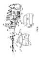
- FIG. 4Aillustrates a third LIDAR, according to an example embodiment.
- FIG. 4Billustrates a partial cross-section view of the third LIDAR of FIG. 4A .
- FIG. 4Cillustrates a three-dimensional representation of an environment based on data from the third LIDAR of FIG. 4A , according to an example embodiment.
- FIG. 5is a flowchart of a method, according to an example embodiment.
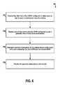
- FIG. 6is a flowchart of another method, according to an example embodiment.
- FIG. 7is a flowchart of yet another method, according to an example embodiment.
- FIG. 8illustrates a vehicle operating in an environment that includes one or more objects, according to an example embodiment.
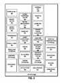
- FIG. 9is a simplified block diagram of a vehicle, according to an example embodiment.
- FIG. 10depicts a computer readable medium configured according to an example embodiment.
- LIDARlight detection and ranging
- a mounting position and/or configuration of a LIDARmay be undesirable for some object detection/identification scenarios.
- a LIDAR positioned at a front side of a vehiclemay be unable to scan the environment for objects behind the vehicle.
- a LIDAR positioned at a top side of the vehiclemay have a 360-degree field-of-view (e.g., by rotating the LIDAR), but may not detect objects near the vehicle due to the geometry of the LIDAR position at the top side of the vehicle.
- a LIDAR that is scanning a wide field-of-view (FOV) for a scanning durationmay provide a lower angular resolution 3D map of the environment than a similar LIDAR that is scanning a narrower FOV over the same scanning duration.
- the lower resolutionmay be sufficient for identifying medium range objects (e.g., within a threshold distance to the vehicle), but may be insufficient to identify long range objects (e.g., outside the threshold distance).
- adjusting the scanning durationmay affect a refresh rate of the LIDAR (i.e., rate at which the LIDAR scans the entire FOV).
- a high refresh ratemay allow the LIDAR to quickly detect changes in the FOV (e.g., moving objects, etc.).
- a low refresh ratemay allow the LIDAR to provide higher resolution data.
- a vehiclethat includes multiple light detection and ranging devices (LIDARs) arranged and configured to facilitate scanning an environment around the vehicle according to various road conditions and scenarios.
- LIDARslight detection and ranging devices
- the vehiclemay include a first LIDAR positioned at a top side of the vehicle and configured to scan the environment around the vehicle based on rotation of the first LIDAR about an axis.
- the vehiclemay utilize the first LIDAR to scan the surrounding environment in all directions with a high refresh rate.
- the axis of rotationmay be substantially vertical such that the first LIDAR has a 360-degree FOV horizontally due to the rotation.
- the high refresh ratemay allow the vehicle to detect moving objects (e.g., other cars, etc.) quickly.
- the high refresh rate and the wide 360-degree FOVmay reduce the angular resolution of the first LIDAR and, in turn, the range of distances to objects that can be properly detected and/or identified by the first LIDAR.
- the first LIDARmay be suitable for object detection and identification within a medium range of distances (e.g., 100 meters or less, etc.).
- a medium range of distancese.g., 100 meters or less, etc.
- Other resolutions, ranges, and/or configurations of the first LIDARare possible as well according to various applications of the first LIDAR.
- the “medium” range of distancesmay be more or less than 100 meters depending on a type of the vehicle (e.g., car, boat, plane, etc.) or any other factor.
- the vehiclemay include a second LIDAR configured to scan a particular FOV of the environment that extends away from the vehicle along a viewing direction of the second LIDAR.
- the particular FOV of the second LIDARis narrower (horizontally) than the 360-degree FOV of the first LIDAR.
- the second LIDARmay have a lower refresh rate than the refresh rate of the first LIDAR.
- the narrower FOV and/or the lower refresh ratemay allow the second LIDAR to have a higher resolution than the first LIDAR.
- the second LIDARmay be suitable for detection and/or identification of objects within a long range of distances (e.g., greater than the medium range of the first LIDAR).
- the higher resolution data from the second LIDARmay be suitable for identification of smaller objects (e.g., debris, etc.) that are difficult to identify using the lower resolution data from the first LIDAR, even within the medium range of the first LIDAR.
- the vehiclemay detect a small object using data from the first LIDAR, adjust the viewing direction (e.g., using a motor, etc.) of the second LIDAR to correspond to a FOV of the environment that includes the detected small object, and thereby identify the small object using higher resolution data from the second LIDAR.
- the second LIDARmay be positioned adjacent to the first LIDAR at the top side of the vehicle.
- other positions, resolutions, ranges and/or configurations of the second LIDARare possible as well and are described in greater detail within exemplary embodiments of the present disclosure.
- the vehiclemay include a third LIDAR positioned at a given side of the vehicle other than the top side.
- the third LIDARmay be mounted to a front side (e.g., bumper, hood, etc.), back side (e.g., trunk, etc.), or any other side (e.g., driver side, passenger side, etc.).
- the third LIDARmay scan a given FOV of the environment extending away from the given side.
- the first LIDAR and/or the second LIDARmay be unable to detect objects that are very close to the vehicle due to the position of the first LIDAR and/or second LIDAR at the top side of the vehicle.
- the third LIDARmay allow detection and/or identification of such objects.
- the third LIDARmay have a resolution that is suitable for detection and/or identification of such objects within a short range of distances to the vehicle.
- the various positions and configurations of the multiple LIDARsmay facilitate autonomous operation of the vehicle.
- the vehiclemay track moving objects in the environment using the combination of LIDARs.
- the vehiclemay utilize the first LIDAR to quickly detect motion of the car, and the second LIDAR to resolve the position of the car relative to lane lines.
- the vehiclemay utilize the third LIDAR to track the motorcycle.
- the vehiclemay adjust its navigational path accordingly (e.g., speed, direction, etc.) to facilitate accidence avoidance.
- each LIDARmay have a configuration (e.g., resolution, FOV, etc.) and/or position that is particularly suitable for one or more road conditions or scenarios.
- the vehiclemay utilize the combination of the multiple LIDARs to facilitate operation of the vehicle in an autonomous mode.
- vehiclemay be broadly construed to cover any moving object, including, for instance, a truck, a van, a semi-trailer truck, a motorcycle, a golf cart, an off-road vehicle, a warehouse transport vehicle, or a farm vehicle, as well as a carrier that rides on a track such as a rollercoaster, trolley, tram, or train car, among other examples.
- FIG. 1Aillustrates a vehicle 100 , according to an example embodiment.
- FIG. 1Ashows a Right Side View, Front View, Back View, and Top View of the vehicle 100 .
- vehicle 100is illustrated in FIG. 1A as a car, as discussed above, other embodiments are possible.
- the example vehicle 100is shown as a vehicle that may be configured to operate in autonomous mode, the embodiments described herein are also applicable to vehicles that are not configured to operate autonomously.
- the example vehicle 100is not meant to be limiting.
- the vehicle 100includes five sensor units 102 , 104 , 106 , 108 , and 110 , and four wheels, exemplified by wheel 112 .
- each of the sensor units 102 - 110may include one or more light detection and ranging devices (LIDARs) that have particular configuration properties to allow scanning an environment around the vehicle 100 according to various road conditions or scenarios. Additionally or alternatively, in some embodiments, the sensor units 102 - 110 may include any combination of global positioning system sensors, inertial measurement units, radio detection and ranging (RADAR) units, cameras, laser rangefinders, LIDARs, and/or acoustic sensors among other possibilities.
- LIDARslight detection and ranging devices
- the sensor unit 102is mounted to a top side of the vehicle 100 opposite to a bottom side of the vehicle 100 where the wheel 112 is mounted. Further, the sensor units 104 - 110 are each mounted to a given side of the vehicle 100 other than the top side. For example, the sensor unit 104 is positioned at a front side of the vehicle 100 , the sensor 106 is positioned at a back side of the vehicle 100 , the sensor unit 108 is positioned at a right side of the vehicle 100 , and the sensor unit 110 is positioned at a left side of the vehicle 100 .
- the sensor units 102 - 110are shown to be mounted in particular locations on the vehicle 100 , in some embodiments, the sensor units 102 - 110 may be mounted elsewhere on the vehicle 100 , either inside or outside the vehicle 100 .
- FIG. 1Ashows the sensor unit 108 mounted to a rear-view mirror of the vehicle 100
- the sensor unit 108may alternatively be positioned in another location along the right side of the vehicle 100 .
- five sensor unitsare shown, in some embodiments more or fewer sensor units may be included in the vehicle 100 . However, for the sake of example, the sensor units 102 - 110 are positioned as shown in FIG. 1A .
- one or more of the sensor units 102 - 110may include one or more movable mounts on which the sensors may be movably mounted.
- the movable mountmay include, for example, a rotating platform. Sensors mounted on the rotating platform could be rotated so that the sensors may obtain information from various directions around the vehicle 100 .
- a LIDAR of the sensor unit 102may have a viewing direction that can be adjusted by actuating the rotating platform to a different direction, etc.
- the movable mountmay include a tilting platform. Sensors mounted on the tilting platform could be tilted within a given range of angles and/or azimuths so that the sensors may obtain information from a variety of angles.
- the movable mountmay take other forms as well.
- one or more of the sensor units 102 - 110may include one or more actuators configured to adjust the position and/or orientation of sensors in the sensor unit by moving the sensors and/or movable mounts.
- Example actuatorsinclude motors, pneumatic actuators, hydraulic pistons, relays, solenoids, and piezoelectric actuators. Other actuators are possible as well.
- the vehicle 100includes one or more wheels such as the wheel 112 that are configured to rotate to cause the vehicle to travel along a driving surface.
- the wheel 112may include at least one tire coupled to a rim of the wheel 112 .
- the wheel 112may include any combination of metal and rubber, or a combination of other materials.
- the vehicle 100may include one or more other components in addition to or instead of those shown.
- FIG. 1Bis a perspective view of the sensor unit 102 positioned at the top side of the vehicle 100 shown in FIG. 1A .
- the sensor unit 102includes a first LIDAR 120 , a second LIDAR 122 , a dividing structure 124 , and light filter 126 .
- the first LIDAR 120may be configured to scan an environment around the vehicle 100 by rotating about an axis (e.g., vertical axis, etc.) continuously while emitting one or more light pulses and detecting reflected light pulses off objects in the environment of the vehicle, for example.
- the first LIDAR 120may be configured to repeatedly rotate about the axis to be able to scan the environment at a sufficiently high refresh rate to quickly detect motion of objects in the environment.
- the first LIDAR 120may have a refresh rate of 10 Hz (e.g., ten complete rotations of the first LIDAR 120 per second), thereby scanning a 360-degree FOV around the vehicle ten times every second.
- a 3D map of the surrounding environmentmay be determined based on data from the first LIDAR 120 .
- the first LIDAR 120may include a plurality of light sources that emit 64 laser beams having a wavelength of 905 nm.
- the 3D map determined based on the data from the first LIDAR 120may have a 0.2° (horizontal) ⁇ 0.3° (vertical) angular resolution, and the first LIDAR 120 may have a 360° (horizontal) ⁇ 20° (vertical) FOV of the environment.
- the 3D mapmay have sufficient resolution to detect or identify objects within a medium range of 100 meters from the vehicle 100 , for example.
- other configurationse.g., number of light sources, angular resolution, wavelength, range, etc. are possible as well.
- the second LIDAR 122may be configured to scan a narrower FOV of the environment around the vehicle 100 .
- the second LIDAR 122may be configured to rotate (horizontally) for less than a complete rotation about a similar axis.
- the second LIDAR 122may have a lower refresh rate than the first LIDAR 120 .
- the vehicle 100may determine a 3D map of the narrower FOV of the environment using the data from the second LIDAR 122 .
- the 3D map in this casemay have a higher angular resolution than the corresponding 3D map determined based on the data from the first LIDAR 120 , and may thus allow detection/identification of objects that are further than the medium range of distances of the first LIDAR 120 , as well as identification of smaller objects within the medium range of distances.
- the second LIDAR 122may have a FOV of 8° (horizontal) ⁇ 15° (vertical), a refresh rate of 4 Hz, and may emit one narrow beam having a wavelength of 1550 nm.
- the 3D map determined based on the data from the second LIDAR 122may have an angular resolution of 0.1° (horizontal) ⁇ 0.03° (vertical), thereby allowing detection/identification of objects within a long range of 300 meters to the vehicle 100 .
- angular resolution0.1° (horizontal) ⁇ 0.03° (vertical)
- other configurationse.g., number of light sources, angular resolution, wavelength, range, etc. are possible as well.
- the vehicle 100may be configured to adjust a viewing direction of the second LIDAR 122 .
- the second LIDAR 122may be mounted to a stepper motor (not shown) that allows adjusting the viewing direction of the second LIDAR 122 to directions other than that shown in FIG. 1B .
- the second LIDAR 122may be steerable to scan the narrow FOV along any viewing direction from the vehicle 100 .
- first LIDAR 120 and the second LIDAR 122are described in greater detail within exemplary embodiments herein.
- the dividing structure 124may be formed from any solid material suitable for supporting the first LIDAR 120 and/or optically isolating the first LIDAR 120 from the second LIDAR 122 .
- Example materialsmay include metals, plastics, foam, among other possibilities.
- the light filter 126may be formed from any material that is substantially transparent to light having wavelengths with a wavelength range, and substantially opaque to light having wavelengths outside the wavelength range.
- the light filter 126may allow light having the first wavelength of the first LIDAR 120 (e.g., 905 nm) and the second wavelength of the second LIDAR 122 (e.g., 1550 nm) to propagate through the light filter 126 .
- the light filter 126is shaped to enclose the first LIDAR 120 and the second LIDAR 122 .
- the light filter 126may also be configured to prevent environmental damage to the first LIDAR 120 and the second LIDAR 122 , such as accumulation of dust or collision with airborne debris among other possibilities.
- the light filter 126may be configured to reduce visible light propagating through the light filter 126 .
- the light filter 126may improve an aesthetic appearance of the vehicle 100 by enclosing the first LIDAR 120 and the second LIDAR 122 , while reducing visibility of the components of the sensor unit 102 from a perspective of an outside observer, for example.
- the light filter 126may be configured to allow visible light as well as the light from the first LIDAR 120 and the second LIDAR 122 .
- portions of the light filter 126may be configured to allow different wavelength ranges to propagate through the light filter 126 .
- an upper portion of the light filter 126 above the dividing structure 124may be configured to allow propagation of light within a first wavelength range that includes the first wavelength of the first LIDAR 120 .
- a lower portion of the light filter 126 below the dividing structure 124may be configured to allow propagation of light within a second wavelength range that includes the second wavelength of the second LIDAR 122 .
- the wavelength range associated with the light filter 126may include both the first wavelength of the first LIDAR 120 and the second wavelength of the second LIDAR 122 .
- the light filter 126having a dome shape, and may therefore be configured as a dome-shaped housing for the first LIDAR 120 and the second LIDAR 122 .
- the dome-shaped housinge.g., light filter 126
- the first LIDAR 120may be disposed within the dome-shaped housing.
- the second LIDAR 122may also be disposed within the dome-shaped housing and may be positioned between the first LIDAR 120 and the top side of the vehicle 100 as shown in FIG. 1B .
- FIG. 1Cis a perspective view of the sensor unit 104 positioned at the front side of the vehicle 100 shown in FIG. 1A .
- the sensor units 106 , 108 , and 110may be configured similarly to the sensor unit 104 illustrated in FIG. 1C .
- the sensor unit 104includes a third LIDAR 130 and a light filter 132 .
- the third LIDAR 130may be configured to scan a FOV of the environment around the vehicle 100 that extends away from a given side of the vehicle 100 (i.e., the front side) where the third LIDAR 130 is positioned.
- the third LIDAR 130may be configured to rotate (e.g., horizontally) across a wider FOV than the second LIDAR 122 but less than the 360-degree FOV of the first LIDAR 120 due to the positioning of the third LIDAR 130 .
- the third LIDAR 130may have a FOV of 270° (horizontal) ⁇ 110° (vertical), a refresh rate of 4 Hz, and may emit one laser beam having a wavelength of 905 nm.
- the 3D map determined based on the data from the third LIDAR 130may have an angular resolution of 1.2° (horizontal) ⁇ 0.2° (vertical), thereby allowing detection/identification of objects within a short range of 30 meters to the vehicle 100 .
- angular resolution1.2° (horizontal) ⁇ 0.2° (vertical)
- other configurationse.g., number of light sources, angular resolution, wavelength, range, etc.
- the structure, operation, and functionality of the third LIDAR 130are described in greater detail within exemplary embodiments of the present disclosure.
- the light filter 132may be similar to the light filter 126 of FIG. 1B .
- the light filter 132may be shaped to enclose the third LIDAR 130 .
- the light filter 132may be configured to allow light within a wavelength range that includes the wavelength of light from the third LIDAR 130 to propagate through the light filter 132 .
- the light filter 132may be configured to reduce visible light propagating through the light filter 132 , thereby improving an aesthetic appearance of the vehicle 100 .
- FIGS. 1D-1Eillustrate the vehicle 100 shown in FIG. 1A scanning a surrounding environment, according to an example embodiment.
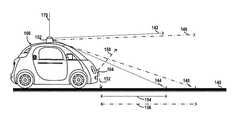
- FIG. 1Dillustrates a scenario where the vehicle 100 is operating on a surface 140 .
- the surface 140may be a driving surface such as a road or a highway, or any other surface.
- the arrows 142 , 144 , 146 , 148 , 150 , 152illustrate light pulses emitted by various LIDARs of the sensor units 102 and 104 at ends of the vertical FOV of the respective LIDAR.
- arrows 142 and 144illustrate light pulses emitted by the first LIDAR 120 of FIG. 1B .
- the first LIDAR 120may emit a series of pulses in the region of the environment between the arrows 142 and 144 and may receive reflected light pulses from that region to detect and/or identify objects in that region. Due to the positioning of the first LIDAR 120 (not shown) of the sensor unit 102 at the top side of the vehicle 100 , the vertical FOV of the first LIDAR 120 is limited by the structure of the vehicle 100 (e.g., roof, etc.) as illustrated in FIG. 1D .
- the positioning of the first LIDAR 120 in the sensor unit 102 at the top side of the vehicle 100allows the first LIDAR 120 to scan all directions around the vehicle 100 by rotating about a substantially vertical axis 170 .
- the arrows 146 and 148illustrate light pulses emitted by the second LIDAR 122 of FIG. 1B at the ends of the vertical FOV of the second LIDAR 122 .
- the second LIDAR 122may also be steerable to adjust a viewing direction of the second LIDAR 122 to any direction around the vehicle 100 in line with the discussion.
- the vertical FOV of the first LIDAR 120(e.g., angle between arrows 142 and 144 ) is 20° and the vertical FOV of the second LIDAR 122 is 15° (e.g., angle between arrows 146 and 148 ).
- other vertical FOVsare possible as well depending, for example, on factors such as structure of the vehicle 100 or configuration of the respective LIDARs.
- the sensor unit 102may scan for objects in the environment of the vehicle 100 in any direction around the vehicle 100 (e.g., by rotating, etc.), but may be less suitable for scanning the environment for objects in close proximity to the vehicle 100 .
- objects within distance 154 to the vehicle 100may be undetected or may only be partially detected by the first LIDAR 120 of the sensor unit 102 due to positions of such objects being outside the region between the light pulses illustrated by the arrows 142 and 144 .
- objects within distance 156may also be undetected or may only be partially detected by the second LIDAR 122 of the sensor unit 102 .
- the third LIDAR 130(not shown) of the sensor unit 104 may be used for scanning the environment for objects that are close to the vehicle 100 .
- the third LIDAR 130may be suitable for scanning the environment for objects within the distance 154 and/or the distance 156 to the vehicle 100 , at least for the portion of the environment extending away from the front side of the vehicle 100 .
- the arrows 150 and 152illustrate light pulses emitted by the third LIDAR 130 at ends of the vertical FOV of the third LIDAR 130 .
- the third LIDAR 130 of the sensor unit 104may be configured to scan a portion of the environment between the arrows 150 and 152 , including objects that are close to the vehicle 100 .
- the vertical FOV of the third LIDAR 130is 110° (e.g., angle between arrows 150 and 152 ).
- other vertical FOVsare possible as well.
- angles between the various arrows 142 - 152 shown in FIG. 1Dare not to scale and are for illustrative purposes only. Thus, in some examples, the vertical FOVs of the various LIDARs may vary as well.
- FIG. 1Eillustrates a top view of the vehicle 100 in a scenario where the vehicle 100 is scanning a surrounding environment.
- each of the various LIDARs of the vehicle 100may have a particular resolution according to its respective refresh rate, FOV, or any other factor.
- the various LIDARsmay be suitable for detection and/or identification of objects within a respective range of distances to the vehicle 100 .
- contours 160 and 162illustrate an example range of distances to the vehicle 100 where objects may be detected/identified based on data from the first LIDAR 120 of the sensor unit 102 .
- close objects within the contour 160may not be properly detected and/or identified due to the positioning of the sensor unit 102 on the top side of the vehicle 100 .
- objects outside of contour 160 and within a medium range of distances (e.g., 100 meters, etc.) defined by the contour 162may be properly detected/identified using the data from the first LIDAR 120 .
- the horizontal FOV of the first LIDAR 120may span 360° in all directions around the vehicle 100 .
- contour 164illustrates a region of the environment where objects may be detected and/or identified using the higher resolution data from the second LIDAR 122 of the sensor unit 102 .
- the contour 164includes objects further away from the vehicle 100 within a long range of distances (e.g., 300 meters, etc.), for example.
- the contour 164indicates a narrower FOV (horizontally) of the second LIDAR 122
- the vehicle 100may be configured to adjust the viewing direction of the second LIDAR 122 to any other direction than that shown in FIG. 1E .
- the vehicle 100may detect an object using the data from the first LIDAR 120 (e.g., within the contour 162 ), adjust the viewing direction of the second LIDAR 122 to a FOV that includes the object, and then identify the object using the higher resolution data from the second LIDAR 122 .
- the horizontal FOV of the second LIDAR 122may be 8°.
- contour 166illustrates a region of the environment scanned by the third LIDAR 130 of the sensor unit 104 .
- the region illustrated by the contour 166includes portions of the environment that may not be scanned by the first LIDAR 120 and/or the second LIDAR 124 , for example.
- the data from the third LIDAR 130has a resolution sufficient to detect and/or identify objects within a short distance (e.g., 30 meters, etc.) to the vehicle 100 .
- FIG. 2Aillustrates a first LIDAR 200 , according to an example embodiment.
- the first LIDAR 200may be similar to the first LIDAR 120 of FIG. 1B , the second LIDAR 122 of FIG. 1B , the third LIDAR 130 of FIG. 1C , and/or any other LIDAR device mounted to a vehicle such as the vehicle 100 .
- the first LIDAR 200may be mounted at a top side of a vehicle such as the vehicle 100 similarly to the first LIDAR 120 of the FIG. 1B .
- the LIDAR device 200includes a housing 210 and a lens 250 .
- light beams 204 emitted by the first LIDAR device 200propagate from the lens 250 along a viewing direction of the first LIDAR 200 toward an environment of the LIDAR device 200 , and reflect off one or more objects in the environment as reflected light 206 .
- the housing 210 included in the LIDAR device 200can provide a platform for mounting the various components included in the LIDAR device 200 .
- the housing 210can be formed from any material capable of supporting the various components of the LIDAR device 200 included in an interior space of the housing 210 .
- the housing 210may be formed from a solid material such as plastic or metal among other possibilities.
- the housing 210can be configured to have a substantially cylindrical shape and to rotate about an axis of the LIDAR device 200 .
- the housing 210can have the substantially cylindrical shape with a diameter of approximately 10 centimeters.
- the axisis substantially vertical.
- a three-dimensional map of a 360-degree view of the environment of the LIDAR device 200can be determined without frequent recalibration of the arrangement of the various components of the LIDAR device 200 .
- the LIDAR device 200can be configured to tilt the axis of rotation of the housing 210 to control the field of view of the LIDAR device 200 .
- the lens 250 mounted to the housing 210can have an optical power to both collimate the emitted light beams 204 , and focus the reflected light 205 from one or more objects in the environment of the LIDAR device 200 onto detectors in the LIDAR device 200 .
- the lens 250has a focal length of approximately 120 mm.
- the LIDAR device 200can be mounted on a mounting structure 260 that rotates about an axis to provide a 360-degree view of the environment surrounding the LIDAR device 200 .
- the mounting structure 260may comprise a movable platform that may tilt in one or more directions to change the axis of rotation of the LIDAR device 200 .
- FIG. 2Bis a cross-section view of the first LIDAR 200 shown in FIG. 2A .
- the housing 210houses a transmit block 220 , a receive block 230 , a shared space 240 , and the lens 250 .
- FIG. 2Bshows an x-y-z axis, in which the z-axis is in a substantially vertical direction.
- the transmit block 220includes a plurality of light sources 222 a - c arranged along a curved focal surface 228 defined by the lens 250 .
- the plurality of light sources 222 a - ccan be configured to emit, respectively, the plurality of light beams 202 a - c having wavelengths within a wavelength range.
- the plurality of light sources 222 a - cmay comprise laser diodes that emit the plurality of light beams 202 a - c having the wavelengths within the wavelength range.
- the plurality of light beams 202 a - care reflected by mirror 224 through an exit aperture 226 into the shared space 240 and towards the lens 250 .
- the light sources 222 a - ccan include laser diodes, light emitting diodes (LED), vertical cavity surface emitting lasers (VCSEL), organic light emitting diodes (OLED), polymer light emitting diodes (PLED), light emitting polymers (LEP), liquid crystal displays (LCD), microelectromechanical systems (MEMS), or any other device configured to selectively transmit, reflect, and/or emit light to provide the plurality of emitted light beams 202 a - c .
- the light sources 222 a - ccan be configured to emit the emitted light beams 202 a - c in a wavelength range that can be detected by detectors 232 a - c included in the receive block 230 .
- the wavelength rangecould, for example, be in the ultraviolet, visible, and/or infrared portions of the electromagnetic spectrum.
- the wavelength rangecan be a narrow wavelength range, such as provided by lasers.
- the wavelength rangeincludes wavelengths that are approximately 905 nm.
- the light sources 222 a - ccan be configured to emit the emitted light beams 202 a - c in the form of pulses.
- the plurality of light sources 222 a - ccan be disposed on one or more substrates (e.g., printed circuit boards (PCB), flexible PCBs, etc.) and arranged to emit the plurality of light beams 202 a - c towards the exit aperture 226 .
- PCBprinted circuit boards
- FIG. 2Bshows that the curved focal surface 228 is curved in the x-y plane
- the plurality of light sources 222 a - cmay be arranged along a focal surface that is curved in a vertical plane.
- the curved focal surface 228can have a curvature in a vertical plane
- the plurality of light sources 222 a - ccan include additional light sources arranged vertically along the curved focal surface 228 and configured to emit light beams directed at the mirror 224 and reflected through the exit aperture 226 .
- the detectors 232 a - cmay also include additional detectors that correspond to additional light sources of the light sources 222 a - c .
- the light sources 222 a - cmay include additional light sources arranged horizontally along the curved focal surface 228 .
- the light sources 222 a - cmay include 64 light sources that emit light having a wavelength of 905 nm.
- the 64 light sourcesmay be arranged in four columns, each comprising 16 light sources, along the curved focal surface 228 .
- the detectors 232 a - cmay include 64 detectors that are arranged similarly (e.g., 4 columns comprising 16 detectors each, etc.) along curved focal surface 238 .
- the light sources 222 a - c and the detectors 232 a - cmay include more or less light sources and/or detectors than those shown in FIG. 2B .
- the plurality of light beams 202 a - cmay converge towards the exit aperture 226 .
- the exit aperture 226may be minimally sized while being capable of accommodating vertical and horizontal extents of the plurality of light beams 202 a - c .
- the curved focal surface 228can be defined by the lens 250 .
- the curved focal surface 228may correspond to a focal surface of the lens 250 due to shape and composition of the lens 250 .
- the plurality of light sources 222 a - ccan be arranged along the focal surface defined by the lens 250 at the transmit block.
- the plurality of light beams 202 a - cpropagate in a transmit path that extends through the transmit block 220 , the exit aperture 226 , and the shared space 240 towards the lens 250 .
- the lens 250collimates the plurality of light beams 202 a - c to provide collimated light beams 204 a - c into an environment of the LIDAR device 200 .
- the collimated light beams 204 a - ccorrespond, respectively, to the plurality of light beams 202 a - c .
- the collimated light beams 204 a - creflect off one or more objects in the environment of the LIDAR device 200 as reflected light 206 .
- the reflected light 206may be focused by the lens 250 into the shared space 240 as focused light 208 traveling along a receive path that extends through the shared space 240 onto the receive block 230 .
- the focused light 208may be reflected by the reflective surface 242 as focused light 208 a - c propagating towards the receive block 230 .
- the lens 250may be capable of both collimating the plurality of light beams 202 a - c and focusing the reflected light 206 along the receive path 208 towards the receive block 230 due to shape and composition of the lens 250 .
- the lens 250can have an aspheric surface 252 facing outside of the housing 210 and a toroidal surface 254 facing the shared space 240 .
- the exit aperture 226is included in a wall 244 that separates the transmit block 220 from the shared space 240 .
- the wall 244can be formed from a transparent material (e.g., glass) that is coated with a reflective material 242 .
- the exit aperture 226may correspond to the portion of the wall 244 that is not coated by the reflective material 242 . Additionally or alternatively, the exit aperture 226 may comprise a hole or cut-away in the wall 244 .
- the focused light 208is reflected by the reflective surface 242 and directed towards an entrance aperture 234 of the receive block 230 .
- the entrance aperture 234may comprise a filtering window configured to allow wavelengths in the wavelength range of the plurality of light beams 202 a - c emitted by the plurality of light sources 222 a - c and attenuate other wavelengths.
- the focused light 208 a - c reflected by the reflective surface 242 from the focused light 208propagates, respectively, onto a plurality of detectors 232 a - c.
- the plurality of detectors 232 a - ccan be arranged along a curved focal surface 238 of the receive block 230 .
- FIG. 2shows that the curved focal surface 238 is curved along the x-y plane (horizontal plane), additionally or alternatively, the curved focal surface 238 can be curved in a vertical plane.
- the curvature of the focal surface 238is also defined by the lens 250 .
- the curved focal surface 238may correspond to a focal surface of the light projected by the lens 250 along the receive path at the receive block 230 .
- the detectors 232 a - cmay comprise photodiodes, avalanche photodiodes, phototransistors, cameras, active pixel sensors (APS), charge coupled devices (CCD), cryogenic detectors, or any other sensor of light configured to receive focused light 208 a - c having wavelengths in the wavelength range of the emitted light beams 202 a - c.
- APSactive pixel sensors
- CCDcharge coupled devices
- cryogenic detectorsor any other sensor of light configured to receive focused light 208 a - c having wavelengths in the wavelength range of the emitted light beams 202 a - c.
- Each of the focused light 208 a - ccorresponds, respectively, to the emitted light beams 202 a - c and is directed onto, respectively, the plurality of detectors 232 a - c .
- the detector 232 ais configured and arranged to received focused light 208 a that corresponds to collimated light beam 204 a reflected of the one or more objects in the environment of the LIDAR device 200 .
- the collimated light beam 204 acorresponds to the light beam 202 a emitted by the light source 222 a .
- the detector 232 areceives light that was emitted by the light source 222 a
- the detector 232 breceives light that was emitted by the light source 222 b
- the detector 232 creceives light that was emitted by the light source 222 c.
- At least one aspect of the one or more object in the environment of the LIDAR device 200may be determined. For example, by comparing a time when the plurality of light beams 202 a - c were emitted by the plurality of light sources 222 a - c and a time when the plurality of detectors 232 a - c received the focused light 208 a - c , a distance between the LIDAR device 200 and the one or more object in the environment of the LIDAR device 200 may be determined. In some examples, other aspects such as shape, color, material, etc. may also be determined.
- the LIDAR device 200may be rotated about an axis to determine a three-dimensional map of the surroundings of the LIDAR device 200 .
- the LIDAR device 200may be rotated about a substantially vertical axis as illustrated by arrow 290 .
- the LIDAR device 200is rotated counter clock-wise about the axis as illustrated by the arrow 290 , additionally or alternatively, the LIDAR device 200 may be rotated in the clockwise direction.
- the LIDAR device 200may be rotated 360 degrees about the axis, similarly to the first LIDAR 120 of FIG. 1B .
- the LIDAR device 200may be rotated back and forth along a portion of the 360 degree view of the LIDAR device 200 , similarly to the second LIDAR 122 of FIG. 1B .
- the LIDAR device 200may be mounted on a platform that wobbles back and forth about the axis without making a complete rotation.
- the arrangement of the light sources 222 a - c and the detectors 232 a - cmay allow the LIDAR device 200 to have a particular vertical field-of-view.
- the vertical FOV of the LIDAR device 200is 20°.
- the rotation of the LIDAR device 200allows the LIDAR device 200 to have a 360° horizontal FOV.
- the rate of rotationmay allow the device to have a particular refresh rate. In one example, the refresh rate is 10 Hz.
- the refresh rate along with the arrangement of the light sources 222 a - c and the detectors 232 a - cmay also allow the LIDAR device 300 to have a particular angular resolution. In one example, the angular resolution is 0.2° ⁇ 0.3°.
- the various parameters such as the refresh rate and the angular resolutionmay vary according to the configuration of the LIDAR device 200 . Further, in some examples, the LIDAR device 200 may include additional or fewer components than those shown in FIGS. 2A-2B .
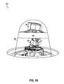
- FIG. 2Cillustrates a three-dimensional (3D) representation 292 of an environment based on data from the first LIDAR 200 of FIG. 2A , according to an example embodiment.
- the 3D representation 292may be generated by a computing device as a 3D point cloud based on the data from the first LIDAR 200 .
- Each point of the 3D cloudmay be associated with a reflected light pulse from the reflected light beams 206 shown in FIG. 2B .
- points at a greater distance from the LIDAR 200are further from one another due to the angular resolution of the LIDAR 200 .
- the 3D representation 292includes a scan of the environment in all directions (360° horizontally) as shown in FIG. 2C .
- a region 294 of the 3D representation 292does not include any points.
- the region 294may correspond to the contour 160 ( FIG. 1E ) around the vehicle 100 that the first LIDAR 120 of FIG. 1B is unable to scan due to positioning at the top side of the vehicle 100 .
- a region 296is indicative of objects in the environment of the LIDAR device 200 .
- the objects in the region 296may correspond to pedestrians, vehicles, or other obstacles in the environment of the LIDAR device 200 .
- the vehicle 100may utilize the 3D representation 292 to navigate the vehicle away from region 296 towards region 298 that does not include the obstacles of the region 296 .
- FIG. 3Aillustrates a second LIDAR 300 , according to an example embodiment.
- the second LIDAR 300may be similar to the first LIDAR 120 of FIG. 1B , the second LIDAR 122 of FIG. 1B , the third LIDAR 130 of FIG. 1C , and/or any other LIDAR mounted to a vehicle such as the vehicle 100 .
- the second LIDAR 300may be mounted at a top side of a vehicle such as the vehicle 100 similarly to the second LIDAR 122 of the FIG. 1B .
- the LIDAR device 300includes an optics assembly 310 , a mirror 320 , a pin 322 , and a platform/stepper motor 330 .
- light beams 304 emitted by the second LIDAR device 300propagate away from the mirror 320 along a viewing direction of the second LIDAR 300 toward an environment of the LIDAR device 300 , and reflect of one or more objects in the environment as reflected light 306 .
- the optics assembly 310may be configured to emit light pulses towards the mirror 320 that are then reflected by the mirror 320 as the emitted light 304 . Further, the optics assembly 310 may be configured to receive reflected light 306 that is reflected off the mirror 320 .
- the optics assembly 310may include a single laser emitter that is configured to provide a narrow beam having a wavelength of 1550 nm. In this embodiment, the narrow beam may have a high energy sufficient for detection of objects within a long range of distances, similarly to the second LIDAR 122 of FIG. 1B . In other embodiments, the optics assembly 310 may include multiple light sources similarly to the LIDAR 200 of FIGS. 2A-2B .
- the optics assembly 310may include a single lens for both collimation of emitted light 304 and focusing of reflected light 306 .
- the optics assembly 310may include a first lens for collimation of emitted light 304 and a second lens for focusing of reflected light 306 .
- the mirror 320may be arranged to steer emitted light 304 from the optics assembly 310 towards the viewing direction of the LIDAR 300 as illustrated in FIG. 3A .
- the mirror 320may be arranged to steer reflected light 306 from the environment towards the optics assembly 310 .
- the pin 322may be configured to mount the mirror 320 to the LIDAR device 300 .
- the pin 322can be formed from any material capable of supporting the mirror 320 .
- the pin 322may be formed from a solid material such as plastic or metal among other possibilities.
- the LIDAR 300may be configured to rotate the mirror 320 about the pin 322 over a given range of angles to steer the emitted light 304 vertically.
- the LIDAR 300may rotate the mirror 320 about the pin 322 over the range of angles of 15°.
- the vertical FOV of the LIDAR 300may correspond to 15°.
- other vertical FOVsare possible as well according to various factors such as the mounting position of the LIDAR 300 or any other factor.
- the platform 330can be formed from any material capable of supporting various components of the LIDAR 300 such as the optics assembly 310 and the mirror 320 .
- the platform 330may be formed from a solid material such as plastic or metal among other possibilities.
- the platform 330may be configured to rotate about an axis of the LIDAR device 300 .
- the platform 330may include or may be a motor such as a stepper motor to facilitate such rotation.
- the axisis substantially vertical. By rotating the platform 330 that supports the various components, in some examples, the platform 330 may steer the emitted light 304 horizontally, thus allowing the LIDAR 300 to have a horizontal FOV.
- the platform 330may rotate for a defined amount of rotation such as 8°.
- the LIDAR 300may thus have a horizontal FOV of 8°, similarly to the second LIDAR 122 of FIG. 1B .
- the platform 330may rotate for complete 360° rotation such that the horizontal FOV is 360°, similarly to the first LIDAR 120 of FIG. 1B .
- the platform 330may rotate for 270°, such that the horizontal FOV is 270° similarly to the third LIDAR 130 of FIG. 1C .
- Other configurations of the platform 330are possible as well.
- the LIDAR 300may provide an alternative device for scanning the environment or a portion thereof to the device of the LIDAR 200 of FIGS. 2A-2B .
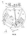
- FIG. 3Billustrates a 3D representation 392 of an environment based on data from the second LIDAR 300 of FIG. 3A , according to an example embodiment.
- the 3D representation 392may be generated, similarly to the 3D representation 292 of FIG. 2C , by a computing device as a 3D point cloud based on the data from the second LIDAR 300 .
- Each point of the 3D cloudmay be associated with a reflected light pulse from the reflected light beams 306 shown in FIG. 3A .
- the 3D representation 392includes a region 394 similar to the region 294 of the 3D representation 292 that may be an unscanned region due to positioning of the second LIDAR 300 at the top side of a vehicle.
- the region 294may correspond to the contour 160 of FIG. 1E around the vehicle 100 .
- the 3D representation 392spans a much narrower field-of-view.
- the FOV scanned by the LIDAR 300 and illustrated in the 3D representation 392may correspond to the contour 164 of FIG. 1E .
- the 3D representation 392has a higher resolution than the 3D representation 292 . For instance, points in the point cloud are closer to one another and thus some objects in the environment may be easily identified compared to the objects in the environment represented by the 3D representation 292 .
- a vehiclesuch as the vehicle 100 may include a first LIDAR (e.g., first LIDAR 120 ) similar to the first LIDAR 200 and a second LIDAR (e.g., second LIDAR 122 ) similar to the second LIDAR 300 .
- the vehiclemay utilize data from the first LIDAR to generate the 3D representation 292 of FIG. 2C .
- the vehiclemay determine that the region 296 of the 3D representation 292 as a region of interest for further scanning.
- the vehicle in the scenariomay adjust a viewing direction of the second LIDAR to scan the region of interest and obtain the 3D representation 392 of FIG. 3B .
- the vehiclemay process the 3D representation 392 using a computing process such as an image processing algorithm or a shape detection algorithm.
- the vehicle of the scenariomay identify an object in region 396 of the 3D representation 392 as a pedestrian, and another object in region 398 as a light post.
- the vehiclemay then navigate accordingly.
- the vehiclemay navigate to be within a first threshold distance to the objects if the objects include a pedestrian (e.g., as indicated by region 396 ), or a lower second threshold distance if the objects include inanimate objects such as the light post (e.g., indicated by region 398 ) among other possibilities.
- the vehiclemay assign the second LIDAR to track the objects if an animate object is identified (e.g., region 396 ), or may assign the second LIDAR to track other objects if only inanimate objects were identified.
- an animate objecte.g., region 396
- Other navigational operationsare possible in line with the scenario.
- a vehicle that includes a combination of LIDARssuch as the LIDAR 200 and the LIDAR 300 may utilize the respective characteristics of each LIDAR such as refresh rate, resolution, FOV, position, etc., to scan the environment according to various road conditions and/or scenarios.
- FIG. 4Aillustrates a third LIDAR 400 , according to an example embodiment.
- the third LIDAR 400may be similar to the first LIDAR 120 of FIG. 1B , the second LIDAR 122 of FIG. 1B , the third LIDAR 130 of FIG. 1C , and/or any other LIDAR mounted to a vehicle such as the vehicle 100 .
- the third LIDAR 400may be mounted at a front side of a vehicle similarly to the third LIDAR 130 of the FIG. 1C , or to any other side of the vehicle (e.g., in sensor units 106 , 108 , 110 , etc., of the vehicle 100 ).
- the third LIDAR 400includes an optics assembly 410 , a transmit lens 412 , a receive lens 414 , a mirror 420 , a pin 422 , and a motor 430 .
- FIG. 4Ashows an x-y-z axis, in which the z-axis is pointing out of the page, and the x-axis and y-axis define a horizontal plane along the surface of the page.
- the third LIDAR 400may emit light that propagates away from the mirror 420 along a viewing direction of the third LIDAR 400 (e.g., parallel to z-axis shown in FIG. 4A , etc.) toward an environment of the third LIDAR 400 , and may receive reflected light from one or more objects in the environment.
- a viewing direction of the third LIDAR 400e.g., parallel to z-axis shown in FIG. 4A , etc.
- the optics assembly 410may be configured to emit light pulses towards the mirror 420 that are then reflected by the mirror 420 towards the environment. Further, the optics assembly 410 may be configured to receive reflected light that is reflected off the mirror 420 .
- the optics assembly 310may include a single laser emitter that is configured to provide a narrow beam having a wavelength of 905 nm. In other embodiments, the optics assembly 410 may include multiple light sources similarly to the LIDAR 200 of FIGS. 2A-2B .
- the optics assembly 410includes the transmit lens 412 for collimation and/or focusing of emitted light from the optics assembly 410 onto the mirror 420 , and a receive lens 414 for focusing reflected light from the mirror 420 onto one or more detectors (not shown) of the optics assembly 410 .
- the optics assembly 410may alternatively include a single lens for both collimation of emitted light and focusing of reflected light similarly to the lens 250 of the first LIDAR 200 .
- the mirror 420 of the third LIDAR 400may be arranged to steer emitted light from the transmit lens 412 towards the viewing direction of the LIDAR 400 as illustrated in FIG. 4A . Further, for example, the mirror 420 may be arranged to steer reflected light from the mirror 420 towards the receive lens 414 . However, in some examples, unlike the mirror 320 , the mirror 420 may be a triangular mirror that performs complete rotations about an axis defined by the pin. In these examples, the mirror 420 may allow reflecting the emitted light from the optics assembly 410 over a wider vertical FOV than the second LIDAR 300 . In one embodiment, the vertical FOV of the third LIDAR 400 is 110°, similarly to the third LIDAR 130 of FIG. 1C .
- the pin 422may be configured to mount the mirror 420 to the LIDAR device 400 .
- the pin 422can be formed from any material capable of supporting the mirror 420 .
- the pin 422may be formed from a solid material such as plastic or metal among other possibilities.
- the LIDAR 400may be configured to rotate the mirror 420 about the pin 422 for complete rotations to steer emitted light from the optics assembly 410 vertically.
- the LIDAR 400may be configured to rotate the mirror 420 about the pin 422 over a given range of angles to steer the emitted light, similarly to the LIDAR 300 .
- various vertical FOVsare possible by adjusting the rotation the mirror 420 about the pin 422 .
- the motor 430may include any motor such as a stepper motor, an electric motor, a combustion motor, a pancake motor, and/or a piezoelectric actuator among other possibilities.
- the motor 430may be configured to rotate various components of the LIDAR 400 (e.g., optics assembly 410 , mirror 420 , pin 422 , etc.) about an axis of the LIDAR device 400 .
- the axismay be substantially vertical similarly to the y-axis shown in FIG. 4A .
- the motor 430may steer the emitted light from that is reflected off the mirror 420 horizontally, thus allowing the LIDAR 400 to have a horizontal FOV.
- the motor 430may rotate for a defined amount of rotation such as 270°.
- the LIDAR 400may thus have a horizontal FOV of 270°, similarly to the third LIDAR 130 of FIG. 1C .
- other amounts of rotationare possible as well (e.g., 360° similarly to the first LIDAR 120 , 8° similarly to the second LIDAR 122 , etc.) thereby allowing a different horizontal FOV for the LIDAR 400 .
- the LIDAR 400may provide an alternative device for scanning the environment or a portion thereof to the device of the LIDAR 200 of FIGS. 2A-2B , and/or the LIDAR 300 of FIG. 3A .
- FIG. 4Billustrates a partial cross-section view of the third LIDAR 400 shown in FIG. 4A . It is noted that some of the components of the third LIDAR 400 are omitted from the illustration of FIG. 4B for convenience in description.
- the optics assembly 410includes a light source 422 .
- the light source 422may be configured to emit one or more light pulses (e.g., laser beams, etc.) towards the transmit lens 412 .
- emitted light 402 apropagates away from the light source 442 towards the transmit lens 412 .
- the light source 422may be similar to the light sources 222 a - c of the LIDAR 200 of FIG. 2B .
- the light source 422may be configured to emit light pulses having a wavelength of 905 nm.
- the transmit lens 412may be configured to collimate the emitted light 402 a into one or more collimated light beams 402 b and/or may be configured to focus the emitted light 402 a as the focused light 402 b onto the mirror 420 .
- the mirror 420may be a triangular mirror as shown that has three reflective surfaces 420 a , 420 b , 420 c . However, in other examples, the mirror 420 may alternatively include more than three reflective surfaces.
- the collimated light 402 bmay then reflect off the reflective surface 402 a and into the environment of the LIDAR 400 as emitted light 402 c .
- a direction of the emitted light 402 cis illustrated in FIG. 4B by arrow 452 .
- the emitted light 402 cmay be steered to have a different direction than that illustrated by arrow 452 .
- the direction 452 of the emitted light 402 cmay instead correspond to a different direction along arrow 450 .
- the LIDAR 400may be configured to have a vertical FOV, for example.
- the mirror 420is configured to rotate about an axis defined by the pin 422 continuously in a clock-wise direction.
- the direction 452 of the emitted light 402 cmay thereby be adjusted also in a clock-wise direction as illustrated by the arrow 450 until the focused light 402 b is reflecting off an edge of the reflective surface 420 a .
- the emitted light 402 cwould be directed towards a maximum extent of the vertical FOV of the LIDAR 400 .
- the collimated light 402 bmay then be focused onto the reflective surface 420 b instead of the reflective surface 420 a .
- the reflected light 402 cmay be steered to a direction that is towards a minimum extent of the vertical FOV of the LIDAR 400 .
- the direction of the emitted light 402 cmay then be adjusted in a clock-wise direction towards the maximum extent of the vertical FOV that corresponds to the light 402 b being focused onto another edge of the reflective surface 420 b .
- the direction of the emitted light 402 cmay then be adjusted to scan the vertical FOV of the LIDAR 400 by reflecting the light 402 b off the reflective surface 420 c instead of the reflective surface 420 b .
- the LIDAR 400may continuously scan the vertical FOV.
- the mirror 420may be alternatively configured to rotate within a given range of angles (e.g., wobble, etc.) to define a narrower vertical field-of-view than that of the scenario described above.
- Other configurations for rotation of the mirror 420are possible as well.
- FIG. 4Cillustrates a 3D representation 492 of an environment based on data from the third LIDAR 400 of FIG. 4A , according to an example embodiment.
- the 3D representation 492may be generated, similarly to the 3D representation 292 and/or the 3D representation 392 , by a computing device as a 3D point cloud based on the data from the third LIDAR 400 .
- Each point of the 3D cloudmay be associated with a reflected light pulse from an object in the environment of the LIDAR 400 .
- the 3D representation 492includes a region 494 , similar to the region 294 of the 3D representation 292 and/or the region 394 of the 3D representation 392 , that may be an unscanned region due to extents of the FOV of the third LIDAR 400 and/or positioning of the LIDAR 400 (e.g., at a given side of the vehicle other than the top side).
- the region 494is much smaller than the regions 294 and 394 .
- the LIDAR 400may be advantageous for scanning nearby objects similarly to the third LIDAR 130 of FIG. 1C .
- the 3D representation 492spans a much wider field-of-view.
- the FOV scanned by the LIDAR 400 and illustrated in the 3D representation 492may correspond to the contour 166 of FIG. 1E .
- the 3D representation 492has a lower resolution than the 3D representation 392 .
- points in the point cloudare further from one another in the 3D representation 492 compared to points in the point cloud of the 3D representation 392 .
- the lower resolutionmay be sufficient to scan the environment for objects within a short range of distances to the third LIDAR 400 .
- a computing devicee.g., vehicle processor, remote server, etc.
- a vehicle that includes a combination of LIDARssuch as the LIDAR 200 , the LIDAR 300 , and/or the LIDAR 400 may utilize the respective characteristics of each LIDAR such as refresh rate, resolution, FOV, position, etc., to scan the environment according to various road conditions and/or scenarios.
- FIG. 5is a flowchart of a method 500 , according to an example embodiment.
- Method 500 shown in FIG. 5presents an embodiment of a method that could be used with any of the vehicle 100 , the LIDARs 120 , 122 , 130 , 200 , 300 , and/or 400 , for example.
- Method 500may include one or more operations, functions, or actions as illustrated by one or more of blocks 502 - 506 . Although the blocks are illustrated in a sequential order, these blocks may in some instances be performed in parallel, and/or in a different order than those described herein. Also, the various blocks may be combined into fewer blocks, divided into additional blocks, and/or removed based upon the desired implementation.
- each blockmay represent a module, a segment, a portion of a manufacturing or operation process, or a portion of program code, which includes one or more instructions executable by a processor for implementing specific logical functions or steps in the process.
- the program codemay be stored on any type of computer readable medium, for example, such as a storage device including a disk or hard drive.
- the computer readable mediummay include non-transitory computer readable medium, for example, such as computer-readable media that stores data for short periods of time like register memory, processor cache and Random Access Memory (RAM).
- the computer readable mediummay also include non-transitory media, such as secondary or persistent long term storage, like read only memory (ROM), optical or magnetic disks, compact-disc read only memory (CD-ROM), for example.
- the computer readable mediamay also be any other volatile or non-volatile storage systems.
- the computer readable mediummay be considered a computer readable storage medium, for example, or a tangible storage device.
- each block in FIG. 5may represent circuitry that is wired to perform the specific logical functions in the process.
- the method 500 and other methods hereinmay be performed by a computing system in a vehicle such as the vehicle 100 .
- the method 500 and other methods hereinmay be performed by a remote system communicatively linked to a vehicle such as the vehicle 100 to provide operation instructions to the vehicle.
- the method 500 and other methods hereinmay be performed by several computing systems in communication with one another such as multiple vehicles or multiple processors on a single vehicle.
- the method 500 and other methods hereinmay be performed by one or more LIDARs mounted to a vehicle such as the vehicle 100 .
- the method 500 and other methods hereinmay facilitate autonomous operation of a vehicle and/or assist in manual operation of a vehicle (e.g., for accidence avoidance).
- the method 500involves scanning an environment around the vehicle based on a first light detection and ranging device (LIDAR).
- the first LIDARmay be positioned at a top side of the vehicle and configured to rotate about an axis, similarly to the first LIDAR 120 of FIG. 1B .
- the first LIDARmay be included in a sensor unit mounted to the top side of the vehicle, such as the sensor unit 102 of FIG. 1A .
- the vehiclemay include one or more wheels that are positioned at a bottom side of the vehicle opposite to the top side, similarly to the wheel 112 of the vehicle 100 .
- the first LIDARmay have a first resolution.
- the first resolutionfor example, may be suitable for scanning the environment around the vehicle for objects within a medium range of distances to the vehicle (e.g., 100 meters, etc.), similarly to the LIDAR 200 of FIGS. 2A-2B .
- the method 500involves scanning a particular field-of-view (FOV) of the environment based on a second LIDAR.
- the particular FOVmay extend away from the vehicle along a viewing direction of the second LIDAR.
- the second LIDARmay be positioned adjacent to the first LIDAR at the top side of the vehicle.
- the second LIDARmay be similar to the second LIDAR 122 of FIG. 1B that is included in the sensor unit 102 mounted to the top side of the vehicle 100 .
- the second LIDARmay have a narrow field-of-view that corresponds to the contour 164 of FIG. 1E .
- the second LIDARmay be suitable for scanning the environment for objects within a long range of distances (e.g., 300 meters, etc.) to the vehicle.
- the second LIDARmay be positioned at a given side other than the top side.
- the second LIDARmay be similar to the third LIDAR 130 of FIG. 1C that is included in the sensor unit 104 mounted to the front side of the vehicle 100 .
- the second LIDARmay be included in any of the sensor units 106 , 108 , 110 that are mounted, respectively, to the back side, right side, and/or left side of the vehicle 100 .
- the second LIDARmay be suitable for scanning the environment for objects within a short range of distances (e.g., 30 meters, etc.) to the vehicle.
- the method 500may also involve adjusting the viewing direction of the second LIDAR based on data received from the first LIDAR.
- the data received from the first LIDARmay indicate a moving object in the environment, such as a car.
- the method 500may include adjusting the viewing direction of the second LIDAR to focus on the moving object and/or track the moving object using given data from the second LIDAR.
- the given data from the second LIDARmay provide a greater resolution (e.g., the second resolution), range, and/or refresh rate suitable for tracking the moving object.
- the data received from the first LIDARmay indicate detection of an object that is difficult to identify due to the first resolution of the first LIDAR.
- the method 500may include adjusting the viewing direction of the second LIDAR to scan the unidentified object and facilitate identification of the object using the greater resolution of the second LIDAR. Other examples are possible as well in line with the discussion above.
- the method 500may also involve determining a three-dimensional (3D) representation of the environment based on data from the first LIDAR having the first resolution.
- the 3D representationmay be similar to the 3D representation 292 of the LIDAR 200 .
- the method 500may also involve identifying a portion of the 3D representation for scanning by the second LIDAR. Continuing with the example scenario, the portion may correspond to the region 296 of the 3D representation 292 . As shown in FIG. 2C , according to the scenario, the region 296 may include various objects that are difficult to identify due to the first resolution of the first LIDAR.
- the method 500may also include adjusting the viewing direction of the second LIDAR to correspond to a FOV of the environment associated with the identified portion of the 3D representation.
- the viewing directionmay be adjusted to the FOV that includes the objects in the region 296 .
- such FOVmay correspond to the FOV illustrated in the 3D representation 392 of FIG. 3B .
- the method 500may also involve updating the portion of the 3D representation to have the second resolution of the second LIDAR based on given data from the second LIDAR.
- the given data from the second LIDARmay allow generating a higher resolution 3D representation for the portion of the environment similarly to the 3D representation 392 .
- the portion of the 3D representationmay be updated with the higher resolution data to facilitate identification of the objects such as the objects in regions 396 and 398 of the 3D representation 392 .
- the method 500may also involve detecting a first object in the environment within a threshold distance to the vehicle based on first data from the first LIDAR.
- the threshold distancemay be based on the first resolution of the first LIDAR.
- the threshold distancemay correspond to a medium range of distances where the first resolution of the first LIDAR may allow detection and/or identification of objects within the medium range.
- the threshold distancemay correspond to the contour 162 , and thus the first object may include any object between the contours 160 and 162 similarly to the first LIDAR 120 of the vehicle 100 .
- the method 500may also involve detecting a second object in the environment at a given distance to the vehicle greater than the threshold distance.
- Detection of the second object at the given distancemay be based on the second resolution of the second LIDAR.
- the second objectmay be included within the contour 164 beyond the threshold distance indicated by the contour 162 . Due to the higher resolution of the second LIDAR, for instance, objects within such region may be detected and/or identified using the second data from the second LIDAR.
- the method 500involves operating the vehicle based on the scans of the environment by the first LIDAR and the second LIDAR.
- the vehiclemay be operated in an autonomous mode.
- the vehiclemay generate 3D maps of the environment or portions thereof similarly to the 3D representations 292 , 392 , and/or 492 .
- the vehiclemay utilize the 3D maps to navigate the vehicle (e.g., adjust speed, direction, etc.) safely by avoiding obstacles among other possibilities.
- the obstacles or objectsfor example, may be detected using an image processing algorithm or other computing method to analyze the 3D maps and detect or identify the various obstacles or objects.
- the vehiclemay be operated in a partially autonomous or manual mode. In this example, the vehicle may notify a driver or operator of the vehicle of the presence or distance to various objects or changing road conditions (e.g., street lights, street signs, etc.).
- the method 500may also involve scanning a given FOV of the environment extending away from a given side of the vehicle other than the top side based on a third LIDAR positioned along the given side.
- the third LIDARmay be similar to the third LIDAR 130 of FIG. 1C that is included in sensor 104 that is mounted to the front side of the vehicle 100 of FIG. 1A .
- the third LIDARmay be another LIDAR mounted to another side, such as a LIDAR included in the sensor units 106 , 108 , and/or 110 of the vehicle 100 .
- the third LIDARmay be suitable for scanning the environment for objects close to the vehicle within a short range of distances (e.g., 30 meters, etc.).
- the method 500 at block 506may involve operating the vehicle based also on the third LIDAR.
- the method 500may involve scanning various portions of the environment around the vehicle, such as the regions indicated by contours 162 , 164 and/or 166 of FIG. 1E , using the first LIDAR, the second LIDAR, and the third LIDAR in line with the discussion above.
- FIG. 6is a flowchart of another method 600 , according to an example embodiment.
- Method 600 shown in FIG. 6presents an embodiment of a method that could be used with any of the vehicle 100 , the LIDARs 120 , 122 , 130 , 200 , 300 , 400 , for example.
- Method 600may include one or more operations, functions, or actions as illustrated by one or more of blocks 602 - 608 . Although the blocks are illustrated in a sequential order, these blocks may in some instances be performed in parallel, and/or in a different order than those described herein. Also, the various blocks may be combined into fewer blocks, divided into additional blocks, and/or removed based upon the desired implementation.
- the method 600involves receiving first data from a first LIDAR configured to rotate about an axis to scan an environment around the vehicle.
- the first LIDARmay be similar to the first LIDAR at block 502 of the method 500 .
- the first LIDARmay be positioned at a top side of the vehicle, similarly to the first LIDAR 120 of FIG. 1B .
- the first LIDARmay be included in a sensor unit mounted to the top side of the vehicle, such as the sensor unit 102 of FIG. 1A .
- the vehiclemay include one or more wheels that are positioned at a bottom side of the vehicle opposite to the top side, similarly to the wheel 112 of the vehicle 100 .
- the first LIDARmay have a first resolution.
- the first resolutionfor example, may be suitable for scanning the environment around the vehicle for objects within a medium range of distances to the vehicle (e.g., 100 meters, etc.), similarly to the LIDAR 200 of FIGS. 2A-2B .
- the first data from the first LIDARmay be received by a computing device included in the vehicle, or may be received by an external computing device in communication with the vehicle.
- the method 600involves receiving second data from a second LIDAR configured to scan a particular FOV of the environment.
- the particular FOVmay extend away from the vehicle along a viewing direction of the second LIDAR.
- the second LIDARmay be positioned adjacent to the first LIDAR at the top side of the vehicle.
- the second LIDARmay be similar to the second LIDAR 122 of FIG. 1B that is included in the sensor unit 102 mounted to the top side of the vehicle 100 .
- the second LIDARmay have a narrow field-of-view that corresponds to the contour 164 of FIG. 1E .
- the second LIDARmay be suitable for scanning the environment for objects within a long range of distances (e.g., 300 meters, etc.) to the vehicle.
- the second LIDARmay be positioned at a given side other than the top side.
- the second LIDARmay be similar to the third LIDAR 130 of FIG. 1C that is included in the sensor unit 104 mounted to the front side of the vehicle 100 .
- the second LIDARmay be included in any of the sensor units 106 , 108 , 110 that are mounted, respectively, to the back side, right side, and/or left side of the vehicle 100 .
- the second LIDARmay be suitable for scanning the environment for objects within a short range of distances (e.g., 30 meters, etc.) to the vehicle.
- the second data from the second LIDARmay be received by a computing device included in the vehicle, or may be received by an external computing device in communication with the vehicle.
- the method 600may also involve determining a 3D representation of the environment based on the first data from the first LIDAR.
- the 3D representationmay have the first resolution of the first LIDAR.
- the 3D representationmay be similar to the 3D representation 292 of FIG. 2C .
- the method 600may also involve detecting one or more objects in the environment based on the 3D representation. Continuing with the example, the one or more objects may be similar to the objects in region 296 of the 3D representation 292 . Further, in these instances, the method 600 may involve adjusting the viewing direction of the second LIDAR to correspond to a FOV of the environment that includes the one or more objects.
- the method 600may also involve determining a given 3D representation of the one or more objects based on the second data from the second LIDAR responsive to adjusting the viewing direction.
- the given 3D representationmay have the second resolution of the second LIDAR.
- the given 3D representationmay be similar to the 3D representation 392 of FIG. 3B , and may thus have the higher second resolution of the second LIDAR.
- the method 600may also involve identifying the one or more objects based on the given 3D representation having the second resolution, and operating the vehicle based on identifying the one or more objects.
- the one or more objectsmay correspond to the objects in region 396 (e.g., pedestrian) and region 398 (e.g., light post).
- the operation of the vehiclemay be adjusted by navigating the vehicle away from the one or more objects, adjusting the speed of the vehicle according to a type of the identified one or more objects (e.g., lower speed if object is a pedestrian, etc.), and/or navigating the vehicle to have a threshold distance to the one or more objects that is based on the type of the one or more objects.
- a type of the identified one or more objectse.g., lower speed if object is a pedestrian, etc.
- Other examplesare possible as well.
- the method 600involves determining operation instructions for the vehicle based on the scans of the environment by the first LIDAR and the second LIDAR.
- the operation instructionsmay include navigating the vehicle away from an obstacle in the environment.
- the operation instructionsmay include adjusting a viewing direction of the second LIDAR to correspond to a FOV of the environment that includes a particular object.
- the operation instructionsmay include causing a display or a speaker in the vehicle to present information regarding one or more objects in the environment.
- the operation instructionsmay include adjusting configuration of various components of the vehicle (e.g., lights, cameras, etc.) in response to detection of objects or other road conditions based on the scans of the environment. Other examples are possible as well.
- the method 600may also involve scanning a given FOV of the environment extending away from a given side of the vehicle other than the top side based on third data from a third LIDAR positioned along the given side.
- the third LIDARmay be similar to the third LIDAR 130 of FIG. 1C , and may have a third resolution suitable for detection of objects within a short range of distances to the vehicle.
- determining the operation instructions at block 606may be based also on the scan of the environment by the third LIDAR.
- the method 600may also involve detecting an object in the environment based on data from the first LIDAR, and identifying the object based on given data from the third LIDAR having the third resolution. For instance, where the object is close to the vehicle, the data from the first LIDAR may only indicate a portion of the object rather than the entire object (e.g., due to an unscanned portion of the environment similarly to region 294 of the 3D representation 292 . In this instance, the method 600 may identify the object using the given data from the third LIDAR that has a FOV that includes the entire object.
- the method 600may also involve determining that a given distance between the object and the vehicle is less than a threshold distance, and responsively obtaining the given data from the third LIDAR to identify the object. For instance, where the detected object is at the border of the unscanned region (e.g., region 294 of the 3D representation 292 ) and thus is at the given distance that is less than the threshold distance, the method 600 may operate the third LIDAR to obtain the given data to identify the object.
- the unscanned regione.g., region 294 of the 3D representation 292
- the method 600involves providing the operation instructions to the vehicle.
- providing the operation instructions at block 608may involve the external computing device communicating the operation instructions to the vehicle (e.g., via a wireless or wired communication interface).
- providing the operation instructionsmay involve the controller providing signals to a navigation system or other control system of the vehicle to adjust operation of the vehicle according to the determined operating instructions.
- Other examplesare possible as well in line with the discussion above.
- FIG. 7is a flowchart of yet another method 700 , according to an example embodiment.
- Method 700 shown in FIG. 7presents an embodiment of a method that could be used with any of the vehicle 100 , the LIDARs 120 , 122 , 130 , 200 , 300 , 400 , for example.
- Method 700may include one or more operations, functions, or actions as illustrated by one or more of blocks 702 - 708 . Although the blocks are illustrated in a sequential order, these blocks may in some instances be performed in parallel, and/or in a different order than those described herein. Also, the various blocks may be combined into fewer blocks, divided into additional blocks, and/or removed based upon the desired implementation.
- the method 700may be used in conjunction with the methods 500 and/or 600 to operate devices and systems herein, such as the vehicle 100 and/or the LIDARs 120 , 122 , 130 , 200 , 300 , 400 . In other examples, the method 700 may be used to operate the devices and the systems herein as an alternative method to the methods 500 and/or 600 . Thus, in some examples, the method 700 may be an additional or alternative method to the methods 500 and/or 600 .
- the method 700involves determining a given distance between a vehicle and an object in an environment of the vehicle based on a first LIDAR of the vehicle, a second LIDAR of the vehicle, or a third LIDAR of the vehicle.
- the first LIDAR, the second LIDAR, and the third LIDARmay be similar, respectively, to the first LIDAR 120 , the second LIDAR 122 , and the third LIDAR 130 of the vehicle 100 .
- the first LIDARmay be positioned at a top side of the vehicle and configured to rotate about an axis to scan the environment around the vehicle
- the second LIDARmay be configured to scan a particular FOV of the environment along a viewing direction of the second LIDAR
- the third LIDARmay be positioned at a given side of the vehicle other than the top side to scan a given FOV of the environment that extends away from the given side.
- the first LIDARmay have a first resolution
- the second LIDARmay have a second resolution
- the third LIDARmay have a third resolution such that each of the LIDARs is suitable for scanning the environment for various objects according to the respective characteristics of the respective LIDAR.
- the first LIDARmay be suitable for detection and/or identification of objects within a medium range of distances to the vehicle (e.g., between contours 160 and 162 of FIG. 1E ), the second LIDAR may be suitable for detection and/or identification of objects within a long range of distances (e.g., within contour 164 of FIG. 1E ), and the third LIDAR may be suitable for detection and/or identification of objects within a short range of distances (e.g., within contour 166 of FIG. 1E ) among other possibilities.
- a medium range of distances to the vehiclee.g., between contours 160 and 162 of FIG. 1E
- the second LIDARmay be suitable for detection and/or identification of objects within a long range of distances (e.g., within contour 164 of FIG. 1E )
- the third LIDARmay be suitable for detection and/or identification of objects within a short range of distances (e.g., within contour 166 of FIG. 1E ) among other possibilities.
- the given distancemay be determined using one or more 3D representations or point clouds that are determined based on data from the respective LIDAR.
- a given 3D representationmay be similar to any of the 3D representations 292 , 392 , 492 illustrated, respectively, in FIGS. 2C, 3B, and 4C .
- the given distancemay be determined by analyzing reflected light pulses from the object to detectors of the respective LIDARs in line with the discussion for LIDARs 200 , 300 , and/or 400 .
- the method 700involves tracking the object based on first data from the first LIDAR based on the given distance being greater than a first threshold and less than a second threshold.
- the objectmay be tracked (e.g., position, motion, speed, direction, etc.) using the first data from the first LIDAR if the object is in the region between contours 160 and 162 .
- the first resolution of the first LIDARmay be suitable for detection/identification of the object, and therefore suitable for tracking the object as well.
- the first thresholdmay correspond to the contour 160 and the second threshold may correspond to the contour 162 .
- the first datamay be similar to the 3D representation 292 of FIG. 2C , or may be data received from the first LIDAR indicating time-of-flight or a shape/intensity of a reflected light pulse detected by the first LIDAR among other possibilities.
- the method 700involves tracking the object based on second data from the second LIDAR based on the given distance being greater than the second LIDAR.
- the objectmay be tracked using the second data from the second LIDAR if the object is in the region beyond contour 162 .
- the viewing direction of the second LIDARmay be adjusted accordingly to keep the object within a FOV of the second LIDAR, illustrated in FIG. 1E as contour 164 .
- the second datamay be similar to the 3D representation 392 of FIG. 3B , or may be data received from the second LIDAR indicating time-of-flight or a shape/intensity of a reflected light pulse detected by the second LIDAR among other possibilities.
- the method 700involves tracking the object based on third data from the third LIDAR based on the given distance being less than the first threshold.
- the objectmay be tracked using the third data from the third LIDAR if the object is in the region indicated by contour 166 .
- Such regionincludes a portion of the environment (e.g., within contour 160 ) that is unscanned by the first LIDAR and/or the second LIDAR due to positioning of the respective LIDARS at the top side of the vehicle.
- the third datamay be similar to the 3D representation 492 of FIG. 4C , or may be data received from the third LIDAR indicating time-of-flight or a shape/intensity of a reflected light pulse detected by the third LIDAR among other possibilities.
- the objectmay move between the various ranges of the various LIDARs, and the method 700 at blocks 704 - 708 may allow continuous tracking of the object using the respective characteristics of each of the first LIDAR, the second LIDAR, and the third LIDAR.
- the vehiclemay utilize the method 700 to track the object as it moves among the various ranges of distances, and thereby facilitate autonomous operation (e.g., navigation) and/or accident avoidance.
- FIG. 8illustrates a vehicle 800 operating in an environment that includes one or more objects, according to an example embodiment.
- the vehicle 800may be similar to the vehicle 100 .
- the vehicle 800includes sensor units 802 , 806 , 808 , and 810 that are similar, respectively, to the sensor units 102 , 106 , 108 , and 110 of the vehicle 100 .
- the sensor unit 802may include a first LIDAR (not shown) and a second LIDAR (not shown) that are similar, respectively, to the first LIDAR 120 and the second LIDAR 122 of the vehicle 100 .
- each of the sensor units 806 - 810may also include a LIDAR similar to the third LIDAR 130 of the vehicle 100 .
- the environment of the vehicle 800includes various objects such as cars 812 , 814 , 816 , road sign 818 , tree 820 , building 822 , street sign 824 , pedestrian 826 , dog 828 , car 830 , driveway 832 , and lane lines including lane line 834 .
- the vehicle 800may perform the methods and processes herein, such as methods 500 - 700 , to facilitate autonomous operation of the vehicle 800 and/or accidence avoidance by the vehicle 800 .
- methods 500 - 700to facilitate autonomous operation of the vehicle 800 and/or accidence avoidance by the vehicle 800 .
- the vehicle 800may utilize the method 500 and/or 600 to detect and/or identify the various objects illustrated in FIG. 8 .
- the vehicle 800may identify the cars 812 - 816 as moving objects that may be pertinent to navigational behavior of the vehicle 800 .
- the vehicle 800may utilize the various scanning resolutions and ranges of the respective LIDARs to properly identify the cars 812 - 816 as moving vehicles.
- the vehicle 800may utilize the method 700 to track the cars 812 - 816 and facilitate such navigation.
- the vehicle 800may adjust its speed, or may change lanes to avoid contact with the cars 812 - 816 based on data from the various LIDARs in the sensor units 802 - 810 .
- the vehicle 800may utilize a LIDAR of the sensor unit 808 and/or 806 to detect, identify, and/or track the car 812 that is in close proximity to the vehicle 800 .
- LIDARfor example, may be similar to the third LIDAR 130 of the vehicle 100 that is suitable for scanning the environment for objects within a short range of distances to the vehicle 800 due to the positioning of such LIDAR (e.g., in the sensor units 808 and/or 810 ).
- LIDARs in the sensor unit 802may be less suitable for scanning the environment for the car 812 due to the positioning of such LIDARs at a top side of the vehicle 800 as shown in FIG. 8 .
- the car 812may be included at least partially within a region of the environment unscanned by the top-mounted LIDARs similar to the region illustrated by contour 160 in FIG. 1E .
- the vehicle 800may utilize a first LIDAR of the sensor unit 802 , similar to the LIDAR 120 of the vehicle 100 , to detect and/or identify the car 814 that is within a threshold distance (e.g., medium range of distances) to the vehicle 800 .
- a threshold distancee.g., medium range of distances
- the car 814may be in the process of changing lanes to the same lane as the vehicle 800 .
- the vehicle 800may need to adjust its speed and/or change lanes to maintain a safe distance to the car 814 .
- data from the first LIDARmay have a first resolution insufficient to detect whether the car 814 is crossing the lane line 834 , or may be insufficient to even detect/identify the lane line 834 .
- the vehicle 800may adjust a viewing direction of a second LIDAR, similar to the second LIDAR 122 of the vehicle 100 , that is included in the sensor unit 802 and that has a higher second resolution than the first resolution of the first LIDAR.
- the vehicle 800may resolve the lane line 834 and/or whether the car 814 is crossing the lane lines.
- the vehicle 800may utilize the higher resolution of the second LIDAR to detect a left light signal of the car 814 to determine that the vehicle 814 is changing lanes among other possibilities.
- the car 816may be driving erratically or moving at a high speed relative to the vehicle 800 among other possibilities.
- the vehicle 800may track the car 816 using the method 700 , and may navigate accordingly (e.g., change lanes, adjust speed, etc.) to avoid contact with the car 816 .
- the vehicle 800may detect the road sign 818 using a medium range LIDAR, similar to the first LIDAR 120 of the vehicle 100 .
- the vehicle 800may adjust a viewing direction of a higher resolution LIDAR and/or longer range LIDAR, similar to the second LIDAR 122 of the vehicle 100 , to analyze the road sign 818 for information.
- the higher resolution of the second LIDARmay allow resolving the information due to differences of reflectivity of features in the road sign 818 .
- the road signmay indicate hazards ahead or a closed lane, and the vehicle 800 may adjust its speed or change lanes accordingly.
- the road signmay indicate traffic delays ahead, and the vehicle 800 may then instruct a navigation system of the vehicle 800 to determine an alternate route.
- Other variations of the scenarioare possible as well.
- the vehiclemay utilizes methods 500 and/or 600 to scan the environment for roadside objects such as the tree 820 , the building 822 , the street sign 824 , the pedestrian 826 , the dog 828 , the car 830 , and/or the driveway 832 .
- roadside objectssuch as the tree 820 , the building 822 , the street sign 824 , the pedestrian 826 , the dog 828 , the car 830 , and/or the driveway 832 .
- the vehicle 800 in the scenariomay identify the objects 820 , 822 , and 824 as inanimate objects and may thus allow the vehicle 800 to change lanes into the lane adjacent to the inanimate objects.
- the vehicle 800may avoid the right lane in anticipation of an event where the animate objects move. Further, the vehicle 800 in the scenario may adjust a viewing direction of a high resolution LIDAR (e.g., second LIDAR 122 , etc.) and/or obtain data from a LIDAR of the sensor unit 808 to identify and/or track such animate objects in line with the methods 500 - 700 .
- a high resolution LIDARe.g., second LIDAR 122 , etc.
- the vehicle 800may avoid the right lane even when the objects are inanimate.
- the vehicle 800may determine that the street sign 824 is a bus stop sign, and may thereby avoid the right lane to allow room for a bus.
- the vehicle 800may determine that the car 830 is moving out of the driveway 832 , and may thereby navigate accordingly to allow room for the car 830 .
- the vehicle 800may utilize data from LIDARs in the sensor units 802 - 810 to determine a state of the vehicle 800 .
- a door, hood, or bumper of the vehicle 800may be open or ajar.
- the data from LIDARs in the sensor units 802 - 810may indicate that such component of the vehicle 800 is open or ajar.
- the LIDAR in the sensor unit 808may be configured to have a 270-degree FOV.
- the LIDARmay not scan components of the vehicle 800 such as the hood.
- the vehicle 800may determine that the right door where the sensor unit 808 is mounted may be open or ajar.
- the present methods and systemsmay facilitate autonomous operation and/or accidence avoidance for a vehicle such as the vehicle 800 by utilizing multiple LIDARs that have characteristics and positions around the vehicle in line with the exemplary embodiments herein.
- FIG. 9is a simplified block diagram of a vehicle 900 , according to an example embodiment.
- the vehicle 900may be similar to the vehicles 100 and/or 800 , and may include multiple LIDARs similar to the LIDARs 200 , 300 , and/or 400 . Further, the vehicle 900 may be configured to perform functions and methods herein such as the methods 500 , 600 , and/or 700 .
- the vehicle 900includes a propulsion system 902 , a sensor system 904 , a control system 906 , peripherals 908 , and a computer system 910 .
- the vehicle 900may include more, fewer, or different systems, and each system may include more, fewer, or different components. Additionally, the systems and components shown may be combined or divided in any number of ways.
- the propulsion system 902may be configured to provide powered motion for the vehicle 900 .
- the propulsion system 902includes an engine/motor 918 , an energy source 920 , a transmission 922 , and wheels/tires 924 .
- the engine/motor 918may be or include any combination of an internal combustion engine, an electric motor, a steam engine, and a Stirling engine. Other motors and engines are possible as well.
- the propulsion system 902may include multiple types of engines and/or motors.
- a gas-electric hybrid carmay include a gasoline engine and an electric motor. Other examples are possible.
- the energy source 920may be a source of energy that powers the engine/motor 918 in full or in part. That is, the engine/motor 918 may be configured to convert the energy source 920 into mechanical energy. Examples of energy sources 920 include gasoline, diesel, propane, other compressed gas-based fuels, ethanol, solar panels, batteries, and other sources of electrical power. The energy source(s) 920 may additionally or alternatively include any combination of fuel tanks, batteries, capacitors, and/or flywheels. In some embodiments, the energy source 920 may provide energy for other systems of the vehicle 900 as well.
- the transmission 922may be configured to transmit mechanical power from the engine/motor 918 to the wheels/tires 924 .
- the transmission 922may include a gearbox, clutch, differential, drive shafts, and/or other elements.
- the drive shaftsmay include one or more axles that are configured to be coupled to the wheels/tires 924 .
- the wheels/tires 924 of vehicle 900may be configured in various formats, including a unicycle, bicycle/motorcycle, tricycle, or car/truck four-wheel format. Other wheel/tire formats are possible as well, such as those including six or more wheels. In any case, the wheels/tires 924 may be configured to rotate differentially with respect to other wheels/tires 924 . In some embodiments, the wheels/tires 924 may include at least one wheel that is fixedly attached to the transmission 922 and at least one tire coupled to a rim of the wheel that could make contact with the driving surface. The wheels/tires 924 may include any combination of metal and rubber, or combination of other materials.
- the propulsion system 902may additionally or alternatively include components other than those shown.
- the sensor system 904may include a number of sensors configured to sense information about an environment in which the vehicle 900 is located, as well as one or more actuators 936 configured to modify a position and/or orientation of the sensors.
- the sensors of the sensor system 904include a Global Positioning System (GPS) 926 , an inertial measurement unit (IMU) 928 , a RADAR unit 930 , a laser rangefinder and/or LIDAR unit 932 , and a camera 934 .
- the sensor system 904may include additional sensors as well, including, for example, sensors that monitor internal systems of the vehicle 900 (e.g., an O 2 monitor, a fuel gauge, an engine oil temperature, etc.). Further, the sensor system 904 may include multiple LIDARs. In some examples, the sensor system 904 may be implemented as multiple sensor units each mounted to the vehicle in a respective position (e.g., top side, bottom side, front side, back side, right side, left side, etc.). Other sensors are possible as well.
- the GPS 926may be any sensor (e.g., location sensor) configured to estimate a geographic location of the vehicle 900 .
- the GPS 926may include a transceiver configured to estimate a position of the vehicle 900 with respect to the Earth.
- the GPS 926may take other forms as well.
- the IMU 928may be any combination of sensors configured to sense position and orientation changes of the vehicle 900 based on inertial acceleration.
- the combination of sensorsmay include, for example, accelerometers and gyroscopes. Other combinations of sensors are possible as well.
- the RADAR unit 930may be any sensor configured to sense objects in the environment in which the vehicle 900 is located using radio signals. In some embodiments, in addition to sensing the objects, the RADAR unit 930 may additionally be configured to sense the speed and/or heading of the objects.
- the laser range finder or LIDAR unit 932may be any sensor configured to sense objects in the environment in which the vehicle 900 is located using lasers.
- the laser rangefinder or LIDAR unit 932may include a laser source and/or laser scanner configured to emit a laser and a detector configured to detect reflections of the laser.
- the laser rangefinder or LIDAR 932may be configured to operate in a coherent (e.g., using heterodyne detection) or an incoherent detection mode.
- the LIDAR unit 932may include multiple LIDARs that each have a unique position and/or configuration suitable for scanning a particular region of an environment around the vehicle 900 .
- the camera 934may be any camera (e.g., a still camera, a video camera, etc.) configured to capture images of the environment in which the vehicle 900 is located. To this end, the camera may take any of the forms described above.
- the sensor system 904may additionally or alternatively include components other than those shown.
- the control system 906may be configured to control operation of the vehicle 900 and its components. To this end, the control system 906 may include a steering unit 938 , a throttle 940 , a brake unit 942 , a sensor fusion algorithm 944 , a computer vision system 946 , a navigation or pathing system 948 , and an obstacle avoidance system 950 .
- the steering unit 938may be any combination of mechanisms configured to adjust the heading of vehicle 900 .
- the throttle 940may be any combination of mechanisms configured to control the operating speed of the engine/motor 918 and, in turn, the speed of the vehicle 900 .
- the brake unit 942may be any combination of mechanisms configured to decelerate the vehicle 900 .
- the brake unit 942may use friction to slow the wheels/tires 924 .
- the brake unit 942may convert the kinetic energy of the wheels/tires 924 to electric current.
- the brake unit 942may take other forms as well.
- the sensor fusion algorithm 944may be an algorithm (or a computer program product storing an algorithm) configured to accept data from the sensor system 904 as an input.
- the datamay include, for example, data representing information sensed at the sensors of the sensor system 904 .
- the sensor fusion algorithm 944may include, for example, a Kalman filter, a Bayesian network, an algorithm for some of the functions of the methods herein, or any another algorithm.
- the sensor fusion algorithm 944may further be configured to provide various assessments based on the data from the sensor system 904 , including, for example, evaluations of individual objects and/or features in the environment in which the vehicle 100 is located, evaluations of particular situations, and/or evaluations of possible impacts based on particular situations. Other assessments are possible as well.
- the computer vision system 946may be any system configured to process and analyze images captured by the camera 934 in order to identify objects and/or features in the environment in which the vehicle 900 is located, including, for example, traffic signals and obstacles. To this end, the computer vision system 946 may use an object recognition algorithm, a Structure from Motion (SFM) algorithm, video tracking, or other computer vision techniques. In some embodiments, the computer vision system 946 may additionally be configured to map the environment, track objects, estimate the speed of objects, etc.
- SFMStructure from Motion
- the navigation and pathing system 948may be any system configured to determine a driving path for the vehicle 900 .
- the navigation and pathing system 948may additionally be configured to update the driving path dynamically while the vehicle 900 is in operation.
- the navigation and pathing system 948may be configured to incorporate data from the sensor fusion algorithm 944 , the GPS 926 , the LIDAR unit 932 , and one or more predetermined maps so as to determine the driving path for vehicle 900 .
- the obstacle avoidance system 950may be any system configured to identify, evaluate, and avoid or otherwise negotiate obstacles in the environment in which the vehicle 900 is located.
- the control system 906may additionally or alternatively include components other than those shown.
- Peripherals 908may be configured to allow the vehicle 900 to interact with external sensors, other vehicles, external computing devices, and/or a user.
- the peripherals 908may include, for example, a wireless communication system 952 , a touchscreen 954 , a microphone 956 , and/or a speaker 958 .
- the wireless communication system 952may be any system configured to wirelessly couple to one or more other vehicles, sensors, or other entities, either directly or via a communication network.
- the wireless communication system 952may include an antenna and a chipset for communicating with the other vehicles, sensors, servers, or other entities either directly or via a communication network.
- the chipset or wireless communication system 952in general may be arranged to communicate according to one or more types of wireless communication (e.g., protocols) such as Bluetooth, communication protocols described in IEEE 802.11 (including any IEEE 802.11 revisions), cellular technology (such as GSM, CDMA, UMTS, EV-DO, WiMAX, or LTE), Zigbee, dedicated short range communications (DSRC), and radio frequency identification (RFID) communications, among other possibilities.
- the wireless communication system 952may take other forms as well.
- the touchscreen 954may be used by a user to input commands to the vehicle 900 .
- the touchscreen 954may be configured to sense at least one of a position and a movement of a user's finger via capacitive sensing, resistance sensing, or a surface acoustic wave process, among other possibilities.
- the touchscreen 954may be capable of sensing finger movement in a direction parallel or planar to the touchscreen surface, in a direction normal to the touchscreen surface, or both, and may also be capable of sensing a level of pressure applied to the touchscreen surface.
- the touchscreen 954may be formed of one or more translucent or transparent insulating layers and one or more translucent or transparent conducting layers.
- the touchscreen 954may take other forms as well.
- the microphone 956may be configured to receive audio (e.g., a voice command or other audio input) from a user of the vehicle 900 .
- the speakers 958may be configured to output audio to the user of the vehicle 900 .
- the peripherals 908may additionally or alternatively include components other than those shown.
- the computer system 910may be configured to transmit data to, receive data from, interact with, and/or control one or more of the propulsion system 902 , the sensor system 904 , the control system 906 , and the peripherals 908 .
- the computer system 910may be communicatively linked to one or more of the propulsion system 902 , the sensor system 904 , the control system 906 , and the peripherals 908 by a system bus, network, and/or other connection mechanism (not shown).
- the computer system 910may be configured to control operation of the transmission 922 to improve fuel efficiency.
- the computer system 910may be configured to cause the camera 934 to capture images of the environment.
- the computer system 910may be configured to store and execute instructions corresponding to the sensor fusion algorithm 944 .
- the computer system 910may be configured to store and execute instructions for determining a 3D representation of the environment around the vehicle 900 using the LIDAR unit 932 . Other examples are possible as well.
- the computer system 910includes the processor 912 and data storage 914 .
- the processor 912may comprise one or more general-purpose processors and/or one or more special-purpose processors. To the extent the processor 912 includes more than one processor, such processors could work separately or in combination.
- Data storage 914may comprise one or more volatile and/or one or more non-volatile storage components, such as optical, magnetic, and/or organic storage, and data storage 914 may be integrated in whole or in part with the processor 912 .
- data storage 914may contain instructions 916 (e.g., program logic) executable by the processor 912 to execute various vehicle functions (e.g., methods 500 - 700 , etc.).
- Data storage 914may contain additional instructions as well, including instructions to transmit data to, receive data from, interact with, and/or control one or more of the propulsion system 902 , the sensor system 904 , the control system 906 , and/or the peripherals 908 .
- the computer system 910may additionally or alternatively include components other than those shown.
- the vehicle 900further includes a power supply 960 , which may be configured to provide power to some or all of the components of the vehicle 900 .
- the power supply 960may include, for example, a rechargeable lithium-ion or lead-acid battery. In some embodiments, one or more banks of batteries could be configured to provide electrical power. Other power supply materials and configurations are possible as well.
- the power supply 960 and energy source 920may be implemented together as one component, as in some all-electric cars.
- the vehicle 900may include one or more elements in addition to or instead of those shown.
- the vehicle 900may include one or more additional interfaces and/or power supplies.
- Other additional componentsare possible as well.
- data storage 914may further include instructions executable by the processor 912 to control and/or communicate with the additional components.
- one or more components or systemsmay be removably mounted on or otherwise connected (mechanically or electrically) to the vehicle 900 using wired or wireless connections.
- the vehicle 900may take other forms as well.
- FIG. 10depicts a computer readable medium configured according to an example embodiment.
- an example systemmay include one or more processors, one or more forms of memory, one or more input devices/interfaces, one or more output devices/interfaces, and machine readable instructions that when executed by the one or more processors cause the system to carry out the various functions tasks, capabilities, etc., described above.
- FIG. 10is a schematic illustrating a conceptual partial view of an example computer program product that includes a computer program for executing a computer process on a computing device, arranged according to at least some embodiments disclosed herein.
- the example computer program product 1000is provided using a signal bearing medium 1002 .
- the signal bearing medium 1002may include one or more programming instructions 1004 that, when executed by one or more processors may provide functionality or portions of the functionality described above with respect to FIGS. 1-9 .
- the signal bearing medium 1002may be a non-transitory computer-readable medium 1006 , such as, but not limited to, a hard disk drive, a Compact Disc (CD), a Digital Video Disk (DVD), a digital tape, memory, etc.
- the signal bearing medium 1002may be a computer recordable medium 1008 , such as, but not limited to, memory, read/write (R/W) CDs, R/W DVDs, etc.
- the signal bearing medium 1002may be a communication medium 1010 (e.g., a fiber optic cable, a waveguide, a wired communications link, etc.).
- the signal bearing medium 1002may be conveyed by a wireless form of the communications medium 1010 .
- the one or more programming instructions 1004may be, for example, computer executable and/or logic implemented instructions.
- a computing devicemay be configured to provide various operations, functions, or actions in response to the programming instructions 1004 conveyed to the computing device by one or more of the computer readable medium 1006 , the computer recordable medium 1008 , and/or the communications medium 1010 .
- the computer readable medium 1006may also be distributed among multiple data storage elements, which could be remotely located from each other.
- the computing device that executes some or all of the stored instructionscould be an external computer, or a mobile computing platform, such as a smartphone, tablet device, personal computer, wearable device, etc.
- the computing device that executes some or all of the stored instructionscould be remotely located computer system, such as a server.
Landscapes
- Engineering & Computer Science (AREA)
- Physics & Mathematics (AREA)
- Remote Sensing (AREA)
- Radar, Positioning & Navigation (AREA)
- General Physics & Mathematics (AREA)
- Computer Networks & Wireless Communication (AREA)
- Electromagnetism (AREA)
- Optics & Photonics (AREA)
- Aviation & Aerospace Engineering (AREA)
- Automation & Control Theory (AREA)
- Optical Radar Systems And Details Thereof (AREA)
- Traffic Control Systems (AREA)
- Control Of Driving Devices And Active Controlling Of Vehicle (AREA)
- Control Of Position, Course, Altitude, Or Attitude Of Moving Bodies (AREA)
- Measurement Of Optical Distance (AREA)
Abstract
Description
Claims (18)
Priority Applications (39)
| Application Number | Priority Date | Filing Date | Title |
|---|---|---|---|
| US14/668,452US9625582B2 (en) | 2015-03-25 | 2015-03-25 | Vehicle with multiple light detection and ranging devices (LIDARs) |
| CA3008411ACA3008411C (en) | 2015-03-25 | 2016-02-24 | Vehicle with multiple light detection and ranging devices (lidars) |
| HK18106481.3AHK1246858B (en) | 2015-03-25 | 2016-02-24 | Vehicle with multiple light detection and ranging devices (lidars) |
| CN201910634911.2ACN110346815B (en) | 2015-03-25 | 2016-02-24 | Vehicle with multiple light detection and ranging devices (LIDAR) |
| AU2016236026AAU2016236026B2 (en) | 2015-03-25 | 2016-02-24 | Vehicle with multiple light detection and ranging devices (LIDARS) |
| KR1020177030643AKR101954986B1 (en) | 2015-03-25 | 2016-02-24 | Vehicles with multiple LIDARs (LIGHT DETECTION AND RANGING DEVICES) |
| CN201680017854.8ACN107430195B (en) | 2015-03-25 | 2016-02-24 | Vehicles with Multiple Light Detection and Ranging Devices (LIDAR) |
| EP16769254.0AEP3274738B1 (en) | 2015-03-25 | 2016-02-24 | Vehicle with multiple light detection and ranging devices (lidars) |
| SG11201706620PASG11201706620PA (en) | 2015-03-25 | 2016-02-24 | Vehicle with multiple light detection and ranging devices (lidars) |
| SG10201709900XASG10201709900XA (en) | 2015-03-25 | 2016-02-24 | Vehicle with multiple light detection and ranging devices (lidars) |
| CA3183074ACA3183074A1 (en) | 2015-03-25 | 2016-02-24 | Vehicle with multiple light detection and ranging devices (lidars) |
| CA3055622ACA3055622C (en) | 2015-03-25 | 2016-02-24 | Vehicle with multiple light detection and ranging devices (lidars) |
| SG10201806612YASG10201806612YA (en) | 2015-03-25 | 2016-02-24 | Vehicle with multiple light detection and ranging devices (lidars) |
| MX2017012279AMX2017012279A (en) | 2015-03-25 | 2016-02-24 | Vehicle with multiple light detection and ranging devices (lidars). |
| EP25163426.7AEP4567468A3 (en) | 2015-03-25 | 2016-02-24 | Vehicle with multiple light detection and ranging devices (lidars) |
| PCT/US2016/019229WO2016153687A1 (en) | 2015-03-25 | 2016-02-24 | Vehicle with multiple light detection and ranging devices (lidars) |
| KR1020197006048AKR102179292B1 (en) | 2015-03-25 | 2016-02-24 | Vehicle with multiple light detection and ranging devices (lidars) |
| SG10202006439VASG10202006439VA (en) | 2015-03-25 | 2016-02-24 | Vehicle with multiple light detection and ranging devices (lidars) |
| JP2017550241AJP6387470B2 (en) | 2015-03-25 | 2016-02-24 | Vehicle with multiple light detection and ranging devices (LIDAR) |
| CA2980305ACA2980305C (en) | 2015-03-25 | 2016-02-24 | Vehicle with multiple light detection and ranging devices (lidars) |
| US15/455,009US9778364B2 (en) | 2015-03-25 | 2017-03-09 | Vehicle with multiple light detection and ranging devices (LIDARs) |
| US15/493,066US9864063B2 (en) | 2015-03-25 | 2017-04-20 | Vehicle with multiple light detection and ranging devices (LIDARs) |
| IL253808AIL253808B (en) | 2015-03-25 | 2017-08-03 | Vehicle with multiple light detection and ranging devices (lidars) |
| US15/714,326US10120079B2 (en) | 2015-03-25 | 2017-09-25 | Vehicle with multiple light detection and ranging devices (LIDARS) |
| MX2019015303AMX2019015303A (en) | 2015-03-25 | 2017-09-25 | Vehicle with multiple light detection and ranging devices (lidars). |
| US15/715,802US10976437B2 (en) | 2015-03-25 | 2017-09-26 | Vehicle with multiple light detection and ranging devices (LIDARS) |
| JP2017184265AJP6476256B2 (en) | 2015-03-25 | 2017-09-26 | Vehicle with multiple light detection and ranging devices (LIDAR) |
| US15/799,926USRE48961E1 (en) | 2015-03-25 | 2017-10-31 | Vehicle with multiple light detection and ranging devices (LIDARs) |
| IL258118AIL258118B (en) | 2015-03-25 | 2018-03-14 | Vehicle with multiple light detection and ranging devices (lidars) |
| AU2018204466AAU2018204466B2 (en) | 2015-03-25 | 2018-06-20 | Vehicle with multiple light detection and ranging devices (LIDARS) |
| IL263105AIL263105B (en) | 2015-03-25 | 2018-11-19 | Vehicle with multiple light detection and ranging devices (lidars) |
| JP2019017710AJP6734951B2 (en) | 2015-03-25 | 2019-02-04 | Vehicle with multiple light detection and ranging devices (LIDAR) |
| AU2019204204AAU2019204204B2 (en) | 2015-03-25 | 2019-06-14 | Vehicle with multiple light detection and ranging devices (LIDARS) |
| JP2020119203AJP7204709B2 (en) | 2015-03-25 | 2020-07-10 | Vehicles with Multiple Light Detection and Ranging Devices (LIDAR) |
| AU2021200407AAU2021200407B2 (en) | 2015-03-25 | 2021-01-21 | Vehicle with multiple light detection and ranging devices (lidars) |
| US17/194,447US12332379B2 (en) | 2015-03-25 | 2021-03-08 | Vehicle with multiple light detection and ranging devices (LIDARs) |
| AU2022200105AAU2022200105B2 (en) | 2015-03-25 | 2022-01-10 | Vehicle with multiple light detection and ranging devices (lidars) |
| US18/145,149US20230126631A1 (en) | 2015-03-25 | 2022-12-22 | Vehicle with Multiple Light Detection and Ranging devices (LIDARs) |
| JP2022211047AJP2023040126A (en) | 2015-03-25 | 2022-12-28 | Vehicle with multiple light detection and ranging devices (lidars) |
Applications Claiming Priority (1)
| Application Number | Priority Date | Filing Date | Title |
|---|---|---|---|
| US14/668,452US9625582B2 (en) | 2015-03-25 | 2015-03-25 | Vehicle with multiple light detection and ranging devices (LIDARs) |
Related Child Applications (2)
| Application Number | Title | Priority Date | Filing Date |
|---|---|---|---|
| US15/455,009ContinuationUS9778364B2 (en) | 2015-03-25 | 2017-03-09 | Vehicle with multiple light detection and ranging devices (LIDARs) |
| US15/799,926ReissueUSRE48961E1 (en) | 2015-03-25 | 2017-10-31 | Vehicle with multiple light detection and ranging devices (LIDARs) |
Publications (2)
| Publication Number | Publication Date |
|---|---|
| US20160282468A1 US20160282468A1 (en) | 2016-09-29 |
| US9625582B2true US9625582B2 (en) | 2017-04-18 |
Family
ID=56976702
Family Applications (8)
| Application Number | Title | Priority Date | Filing Date |
|---|---|---|---|
| US14/668,452CeasedUS9625582B2 (en) | 2015-03-25 | 2015-03-25 | Vehicle with multiple light detection and ranging devices (LIDARs) |
| US15/455,009ActiveUS9778364B2 (en) | 2015-03-25 | 2017-03-09 | Vehicle with multiple light detection and ranging devices (LIDARs) |
| US15/493,066ActiveUS9864063B2 (en) | 2015-03-25 | 2017-04-20 | Vehicle with multiple light detection and ranging devices (LIDARs) |
| US15/714,326ActiveUS10120079B2 (en) | 2015-03-25 | 2017-09-25 | Vehicle with multiple light detection and ranging devices (LIDARS) |
| US15/715,802Active2036-05-17US10976437B2 (en) | 2015-03-25 | 2017-09-26 | Vehicle with multiple light detection and ranging devices (LIDARS) |
| US15/799,926Active2035-05-06USRE48961E1 (en) | 2015-03-25 | 2017-10-31 | Vehicle with multiple light detection and ranging devices (LIDARs) |
| US17/194,447Active2038-05-05US12332379B2 (en) | 2015-03-25 | 2021-03-08 | Vehicle with multiple light detection and ranging devices (LIDARs) |
| US18/145,149PendingUS20230126631A1 (en) | 2015-03-25 | 2022-12-22 | Vehicle with Multiple Light Detection and Ranging devices (LIDARs) |
Family Applications After (7)
| Application Number | Title | Priority Date | Filing Date |
|---|---|---|---|
| US15/455,009ActiveUS9778364B2 (en) | 2015-03-25 | 2017-03-09 | Vehicle with multiple light detection and ranging devices (LIDARs) |
| US15/493,066ActiveUS9864063B2 (en) | 2015-03-25 | 2017-04-20 | Vehicle with multiple light detection and ranging devices (LIDARs) |
| US15/714,326ActiveUS10120079B2 (en) | 2015-03-25 | 2017-09-25 | Vehicle with multiple light detection and ranging devices (LIDARS) |
| US15/715,802Active2036-05-17US10976437B2 (en) | 2015-03-25 | 2017-09-26 | Vehicle with multiple light detection and ranging devices (LIDARS) |
| US15/799,926Active2035-05-06USRE48961E1 (en) | 2015-03-25 | 2017-10-31 | Vehicle with multiple light detection and ranging devices (LIDARs) |
| US17/194,447Active2038-05-05US12332379B2 (en) | 2015-03-25 | 2021-03-08 | Vehicle with multiple light detection and ranging devices (LIDARs) |
| US18/145,149PendingUS20230126631A1 (en) | 2015-03-25 | 2022-12-22 | Vehicle with Multiple Light Detection and Ranging devices (LIDARs) |
Country Status (11)
| Country | Link |
|---|---|
| US (8) | US9625582B2 (en) |
| EP (2) | EP4567468A3 (en) |
| JP (5) | JP6387470B2 (en) |
| KR (2) | KR102179292B1 (en) |
| CN (2) | CN107430195B (en) |
| AU (5) | AU2016236026B2 (en) |
| CA (4) | CA3008411C (en) |
| IL (3) | IL253808B (en) |
| MX (2) | MX2017012279A (en) |
| SG (4) | SG10202006439VA (en) |
| WO (1) | WO2016153687A1 (en) |
Cited By (49)
| Publication number | Priority date | Publication date | Assignee | Title |
|---|---|---|---|---|
| US20150254803A1 (en)* | 2014-03-05 | 2015-09-10 | Audi Ag | Process for true-to-scale scaling of a recording of a camera sensor |
| US20180081361A1 (en)* | 2016-09-20 | 2018-03-22 | Waymo Llc | Devices and Methods for a Sensor Platform of a Vehicle |
| US10151836B2 (en) | 2016-08-10 | 2018-12-11 | James Thomas O'Keeffe | LIDAR with enhanced utilization of a remotely located mirror |
| US10185027B2 (en) | 2016-08-29 | 2019-01-22 | James Thomas O'Keeffe | Lidar with smart safety-conscious laser intensity |
| US10281923B2 (en) | 2016-03-03 | 2019-05-07 | Uber Technologies, Inc. | Planar-beam, light detection and ranging system |
| US10302746B2 (en)* | 2016-05-18 | 2019-05-28 | James Thomas O'Keeffe | LIDAR system with vehicle-integrated beam guide |
| US10338225B2 (en)* | 2015-12-15 | 2019-07-02 | Uber Technologies, Inc. | Dynamic LIDAR sensor controller |
| US10408940B2 (en) | 2016-09-25 | 2019-09-10 | James Thomas O'Keeffe | Remote lidar with coherent fiber optic image bundle |
| US10412368B2 (en) | 2013-03-15 | 2019-09-10 | Uber Technologies, Inc. | Methods, systems, and apparatus for multi-sensory stereo vision for robotics |
| US10447973B2 (en) | 2017-08-08 | 2019-10-15 | Waymo Llc | Rotating LIDAR with co-aligned imager |
| US10469758B2 (en) | 2016-12-06 | 2019-11-05 | Microsoft Technology Licensing, Llc | Structured light 3D sensors with variable focal length lenses and illuminators |
| US10479376B2 (en) | 2017-03-23 | 2019-11-19 | Uatc, Llc | Dynamic sensor selection for self-driving vehicles |
| US10523880B2 (en) | 2017-09-28 | 2019-12-31 | Waymo Llc | Synchronized spinning LIDAR and rolling shutter camera system |
| US10554881B2 (en) | 2016-12-06 | 2020-02-04 | Microsoft Technology Licensing, Llc | Passive and active stereo vision 3D sensors with variable focal length lenses |
| US10557943B2 (en) | 2016-08-22 | 2020-02-11 | Apple Inc. | Optical systems |
| US10564266B2 (en) | 2016-09-25 | 2020-02-18 | James Thomas O'Keeffe | Distributed LIDAR with fiber optics and a field of view combiner |
| US10569721B2 (en) | 2018-01-04 | 2020-02-25 | Toyota Motor Engineering & Manufacturing North America, Inc. | Autonomous radar roof module |
| US10578719B2 (en) | 2016-05-18 | 2020-03-03 | James Thomas O'Keeffe | Vehicle-integrated LIDAR system |
| USD882426S1 (en) | 2018-09-17 | 2020-04-28 | Waymo Llc | Integrated sensor assembly |
| US10634770B2 (en) | 2016-06-29 | 2020-04-28 | Apple Inc. | Optical systems for remote sensing receivers |
| US10718856B2 (en) | 2016-05-27 | 2020-07-21 | Uatc, Llc | Vehicle sensor calibration system |
| US10746858B2 (en) | 2017-08-17 | 2020-08-18 | Uatc, Llc | Calibration for an autonomous vehicle LIDAR module |
| US10775488B2 (en) | 2017-08-17 | 2020-09-15 | Uatc, Llc | Calibration for an autonomous vehicle LIDAR module |
| US10859678B2 (en) | 2017-01-02 | 2020-12-08 | James Thomas O'Keeffe | Micromirror array for feedback-based image resolution enhancement |
| US10914820B2 (en) | 2018-01-31 | 2021-02-09 | Uatc, Llc | Sensor assembly for vehicles |
| USD910469S1 (en)* | 2018-09-18 | 2021-02-16 | Jenoptik Advanced Systems Gmbh | Rangefinder |
| US20210181350A1 (en)* | 2019-12-12 | 2021-06-17 | GM Global Technology Operations LLC | Lidar vision systems |
| US20210316723A1 (en)* | 2020-04-13 | 2021-10-14 | Toyota Jidosha Kabushiki Kaisha | On-board sensor system |
| US11181619B2 (en) | 2018-06-14 | 2021-11-23 | Waymo Llc | Camera ring structure for autonomous vehicles |
| US11216987B2 (en) | 2019-06-17 | 2022-01-04 | Toyota Research Institute, Inc. | Systems and methods for associating LiDAR points with objects |
| US11340338B2 (en) | 2016-08-10 | 2022-05-24 | James Thomas O'Keeffe | Distributed lidar with fiber optics and a field of view combiner |
| US20220206155A1 (en)* | 2019-10-01 | 2022-06-30 | Panasonic Intellectual Property Management Co., Ltd. | Ranging apparatus and control method |
| US11385331B2 (en) | 2018-01-29 | 2022-07-12 | The Regents Of The University Of California | Enclosure for light detection and ranging unit and related methods |
| US20220329715A1 (en)* | 2017-10-19 | 2022-10-13 | Nvidia Corporation | Calibrating sensors mounted on an autonomous vehicle |
| US11536845B2 (en) | 2018-10-31 | 2022-12-27 | Waymo Llc | LIDAR systems with multi-faceted mirrors |
| US11607804B2 (en) | 2019-05-28 | 2023-03-21 | X Development Llc | Robot configuration with three-dimensional lidar |
| US20230184947A1 (en)* | 2021-12-09 | 2023-06-15 | Here Global B.V. | Method, apparatus, and system for providing a lidar path signature |
| US11883935B2 (en) | 2021-10-20 | 2024-01-30 | Ford Global Technologies, Llc | Assembling a sensor assembly |
| US11899466B2 (en) | 2017-12-29 | 2024-02-13 | Waymo Llc | Sensor integration for large autonomous vehicles |
| USD1014398S1 (en) | 2021-12-23 | 2024-02-13 | Waymo Llc | Vehicle |
| US11933967B2 (en) | 2019-08-22 | 2024-03-19 | Red Creamery, LLC | Distally actuated scanning mirror |
| USD1018337S1 (en) | 2021-12-23 | 2024-03-19 | Waymo Llc | Sensor assembly |
| US12123950B2 (en) | 2016-02-15 | 2024-10-22 | Red Creamery, LLC | Hybrid LADAR with co-planar scanning and imaging field-of-view |
| US12130383B2 (en) | 2019-12-27 | 2024-10-29 | Waymo Llc | Rotatable mirror device |
| US12130203B2 (en) | 2019-07-22 | 2024-10-29 | Bridgestone Corporation | Control method, control device, control system, and tire testing method |
| US12332379B2 (en) | 2015-03-25 | 2025-06-17 | Waymo Llc | Vehicle with multiple light detection and ranging devices (LIDARs) |
| US12399278B1 (en) | 2016-02-15 | 2025-08-26 | Red Creamery Llc | Hybrid LIDAR with optically enhanced scanned laser |
| US12399279B1 (en) | 2016-02-15 | 2025-08-26 | Red Creamery Llc | Enhanced hybrid LIDAR with high-speed scanning |
| US12422534B2 (en) | 2019-03-14 | 2025-09-23 | Waymo Llc | Methods and systems for detecting obstructions on a sensor housing |
Families Citing this family (243)
| Publication number | Priority date | Publication date | Assignee | Title |
|---|---|---|---|---|
| USRE46672E1 (en) | 2006-07-13 | 2018-01-16 | Velodyne Lidar, Inc. | High definition LiDAR system |
| US10739460B2 (en) | 2010-08-11 | 2020-08-11 | Apple Inc. | Time-of-flight detector with single-axis scan |
| US12025807B2 (en) | 2010-10-04 | 2024-07-02 | Gerard Dirk Smits | System and method for 3-D projection and enhancements for interactivity |
| USD731383S1 (en) | 2014-05-23 | 2015-06-09 | Google Inc. | Vehicle door |
| WO2016025502A1 (en) | 2014-08-11 | 2016-02-18 | Gerard Dirk Smits | Three-dimensional triangulation and time-of-flight based tracking systems and methods |
| US10102590B1 (en) | 2014-10-02 | 2018-10-16 | United Services Automobile Association (Usaa) | Systems and methods for unmanned vehicle management |
| US11688014B1 (en) | 2014-10-02 | 2023-06-27 | United Services Automobile Association (Usaa) | Systems and methods for unmanned vehicle management |
| US10365646B1 (en) | 2015-01-27 | 2019-07-30 | United Services Automobile Association (Usaa) | Systems and methods for unmanned vehicle management |
| US11532050B1 (en) | 2015-01-27 | 2022-12-20 | United Services Automobile Association (Usaa) | Unmanned vehicle service delivery |
| US9939810B1 (en) | 2015-04-17 | 2018-04-10 | United Services Automobile Association | Indoor drone flight awareness system |
| JP6235528B2 (en)* | 2015-05-15 | 2017-11-22 | トヨタ自動車株式会社 | Vehicle control device |
| DE102015213694A1 (en)* | 2015-07-21 | 2017-01-26 | Robert Bosch Gmbh | Sensor system for detecting protruding or exposed objects in the vicinity of a vehicle |
| US10282591B2 (en)* | 2015-08-24 | 2019-05-07 | Qualcomm Incorporated | Systems and methods for depth map sampling |
| US10061020B2 (en) | 2015-09-20 | 2018-08-28 | Qualcomm Incorporated | Light detection and ranging (LIDAR) system with dual beam steering |
| US10093181B1 (en) | 2015-09-30 | 2018-10-09 | Waymo Llc | Occupant facing vehicle display |
| ES2946192T3 (en)* | 2015-11-30 | 2023-07-13 | Signify Holding Bv | Distinguishing devices that have positions and directions |
| US10243604B2 (en) | 2015-12-08 | 2019-03-26 | Uber Technologies, Inc. | Autonomous vehicle mesh networking configuration |
| US9432929B1 (en) | 2015-12-08 | 2016-08-30 | Uber Technologies, Inc. | Communication configuration system for a fleet of automated vehicles |
| US10036642B2 (en)* | 2015-12-08 | 2018-07-31 | Uber Technologies, Inc. | Automated vehicle communications system |
| US9603158B1 (en) | 2015-12-08 | 2017-03-21 | Uber Technologies, Inc. | Optimizing communication for automated vehicles |
| US10050760B2 (en) | 2015-12-08 | 2018-08-14 | Uber Technologies, Inc. | Backend communications system for a fleet of autonomous vehicles |
| JP6854828B2 (en) | 2015-12-18 | 2021-04-07 | ジェラルド ディルク スミッツ | Real-time position detection of an object |
| US10169856B1 (en) | 2016-01-27 | 2019-01-01 | United Services Automobile Association (Usaa) | Laser-assisted image processing |
| US10354386B1 (en) | 2016-01-27 | 2019-07-16 | United Services Automobile Association (Usaa) | Remote sensing of structure damage |
| US10627490B2 (en) | 2016-01-31 | 2020-04-21 | Velodyne Lidar, Inc. | Multiple pulse, LIDAR based 3-D imaging |
| EP3203259A1 (en)* | 2016-02-03 | 2017-08-09 | Konica Minolta, Inc. | Optical scanning type object detection device |
| US9902311B2 (en) | 2016-02-22 | 2018-02-27 | Uber Technologies, Inc. | Lighting device for a vehicle |
| US9969326B2 (en) | 2016-02-22 | 2018-05-15 | Uber Technologies, Inc. | Intention signaling for an autonomous vehicle |
| EP3430428B1 (en) | 2016-03-19 | 2025-04-02 | Velodyne Lidar USA, Inc. | Integrated illumination and detection for lidar based 3-d imaging |
| US10343620B2 (en)* | 2016-04-22 | 2019-07-09 | Uber Technologies, Inc. | External sensor assembly for vehicles |
| US10761195B2 (en)* | 2016-04-22 | 2020-09-01 | OPSYS Tech Ltd. | Multi-wavelength LIDAR system |
| USD851508S1 (en) | 2016-05-03 | 2019-06-18 | Uber Technologies, Inc. | External sensor assembly for a vehicle |
| US10838046B2 (en)* | 2016-05-10 | 2020-11-17 | Suteng Innovation Technology Co., Ltd. | Multiline lidar |
| US11237251B2 (en) | 2016-05-11 | 2022-02-01 | Texas Instruments Incorporated | Lidar scanning with expanded scan angle |
| US11106030B2 (en) | 2016-05-11 | 2021-08-31 | Texas Instruments Incorporated | Optical distance measurement system using solid state beam steering |
| WO2017210418A1 (en) | 2016-06-01 | 2017-12-07 | Velodyne Lidar, Inc. | Multiple pixel scanning lidar |
| IL246386B (en)* | 2016-06-22 | 2018-03-29 | Tarantula Tech Ltd | Apparatus for detecting hazardous objects within a designated distance from a surface |
| US10145941B2 (en)* | 2016-07-26 | 2018-12-04 | Toyota Motor Engineering & Manufacturing North America, Inc. | LIDAR sensor attached to an actuator |
| US10471904B2 (en)* | 2016-08-08 | 2019-11-12 | Toyota Motor Engineering & Manufacturing North America, Inc. | Systems and methods for adjusting the position of sensors of an automated vehicle |
| US10298913B2 (en)* | 2016-08-18 | 2019-05-21 | Apple Inc. | Standalone depth camera |
| EP4194887A1 (en)* | 2016-09-20 | 2023-06-14 | Innoviz Technologies Ltd. | Lidar systems and methods |
| FR3056524B1 (en)* | 2016-09-28 | 2018-10-12 | Valeo Systemes D'essuyage | DETECTION SYSTEM FOR MOTOR VEHICLE |
| US9787048B1 (en) | 2016-10-17 | 2017-10-10 | Waymo Llc | Fiber encapsulation mechanism for energy dissipation in a fiber amplifying system |
| US10379540B2 (en)* | 2016-10-17 | 2019-08-13 | Waymo Llc | Light detection and ranging (LIDAR) device having multiple receivers |
| KR102569539B1 (en)* | 2016-11-07 | 2023-08-24 | 주식회사 에이치엘클레무브 | Object sensing system for vehicle and object sensing method for vehicle |
| CN108072877A (en)* | 2016-11-10 | 2018-05-25 | 光宝电子(广州)有限公司 | Optical devices |
| US10845470B2 (en) | 2016-11-16 | 2020-11-24 | Waymo Llc | Methods and systems for protecting a light detection and ranging (LIDAR) device |
| US10502618B2 (en) | 2016-12-03 | 2019-12-10 | Waymo Llc | Waveguide diffuser for light detection using an aperture |
| JP7329444B2 (en) | 2016-12-27 | 2023-08-18 | ジェラルド ディルク スミッツ | Systems and methods for machine perception |
| US10520592B2 (en) | 2016-12-31 | 2019-12-31 | Waymo Llc | Light detection and ranging (LIDAR) device with an off-axis receiver |
| US10942257B2 (en) | 2016-12-31 | 2021-03-09 | Innovusion Ireland Limited | 2D scanning high precision LiDAR using combination of rotating concave mirror and beam steering devices |
| KR102254079B1 (en)* | 2017-01-04 | 2021-05-20 | 현대자동차주식회사 | Vehicle And Control Method Thereof |
| MY204883A (en) | 2017-01-05 | 2024-09-20 | Fraunhofer Ges Zur Frderung Der Angewandten Forschung E V | Generation and use of hd maps |
| SG10201700299QA (en)* | 2017-01-13 | 2018-08-30 | Otsaw Digital Pte Ltd | Three-dimensional mapping of an environment |
| DE102017101945A1 (en)* | 2017-02-01 | 2018-08-02 | Osram Opto Semiconductors Gmbh | Measuring arrangement with an optical transmitter and an optical receiver |
| US10202126B2 (en) | 2017-03-07 | 2019-02-12 | Uber Technologies, Inc. | Teleassistance data encoding for self-driving vehicles |
| US10293818B2 (en) | 2017-03-07 | 2019-05-21 | Uber Technologies, Inc. | Teleassistance data prioritization for self-driving vehicles |
| CN107128255B (en)* | 2017-03-08 | 2020-10-23 | 北京百度网讯科技有限公司 | Sensor assembly |
| EP3373037B1 (en)* | 2017-03-10 | 2023-06-28 | The Hi-Tech Robotic Systemz Ltd | Single casing advanced driver assistance system |
| KR102619582B1 (en) | 2017-03-13 | 2024-01-02 | 옵시스 테크 엘티디 | Eye-Safe Scanning LIDAR System |
| US9869754B1 (en)* | 2017-03-22 | 2018-01-16 | Luminar Technologies, Inc. | Scan patterns for lidar systems |
| EP3593166B1 (en) | 2017-03-31 | 2024-04-17 | Velodyne Lidar USA, Inc. | Integrated lidar illumination power control |
| US20180284246A1 (en)* | 2017-03-31 | 2018-10-04 | Luminar Technologies, Inc. | Using Acoustic Signals to Modify Operation of a Lidar System |
| US10488494B2 (en) | 2017-04-03 | 2019-11-26 | Ford Global Technologies, Llc | Sensor apparatus |
| US10338198B2 (en)* | 2017-04-03 | 2019-07-02 | Ford Global Technologies, Llc | Sensor apparatus |
| CN110869796A (en)* | 2017-04-12 | 2020-03-06 | 感应光子公司 | Device including integrated detector and subminiature vertical cavity surface emitting laser emitter |
| US10303961B1 (en)* | 2017-04-13 | 2019-05-28 | Zoox, Inc. | Object detection and passenger notification |
| US20200150228A1 (en)* | 2017-04-20 | 2020-05-14 | Analog Devices, Inc. | Method of Providing Interference Reduction and a Dynamic Region of Interest in a LIDAR System |
| US20180306905A1 (en)* | 2017-04-20 | 2018-10-25 | Analog Devices, Inc. | Method of Providing a Dynamic Region of interest in a LIDAR System |
| US10552691B2 (en)* | 2017-04-25 | 2020-02-04 | TuSimple | System and method for vehicle position and velocity estimation based on camera and lidar data |
| WO2018196001A1 (en)* | 2017-04-28 | 2018-11-01 | SZ DJI Technology Co., Ltd. | Sensing assembly for autonomous driving |
| USD834971S1 (en) | 2017-04-28 | 2018-12-04 | Waymo Llc | Front sensor housing |
| USD835028S1 (en)* | 2017-04-28 | 2018-12-04 | Waymo Llc | Roof sensor housing |
| USD858381S1 (en) | 2017-04-28 | 2019-09-03 | Waymo Llc | Fender sensor housing |
| DE102017207493A1 (en)* | 2017-05-04 | 2018-11-08 | Robert Bosch Gmbh | Transmitter optics for a LiDAR system, LiDAR system and working device |
| CN110809704B (en) | 2017-05-08 | 2022-11-01 | 威力登激光雷达美国有限公司 | LIDAR data acquisition and control |
| WO2018209096A2 (en) | 2017-05-10 | 2018-11-15 | Gerard Dirk Smits | Scan mirror systems and methods |
| US10564261B2 (en) | 2017-05-11 | 2020-02-18 | Ford Global Technologies, Llc | Autonomous vehicle LIDAR mirror |
| DE202018006696U1 (en)* | 2017-05-15 | 2022-04-01 | Ouster, Inc. | Optical image transmitter with brightness improvement |
| DE102017208700A1 (en) | 2017-05-23 | 2018-11-29 | Robert Bosch Gmbh | Method and device for object detection and LIDAR system |
| KR102616109B1 (en)* | 2017-06-07 | 2023-12-21 | 헤사이 테크놀로지 씨오., 엘티디. | multi line laser radar |
| US11467259B2 (en)* | 2017-06-14 | 2022-10-11 | Mitsubishi Electric Corporation | Optical scanning apparatus, method for controlling same, and vehicle |
| US10473767B2 (en) | 2017-06-19 | 2019-11-12 | Hesai Photonics Technology Co., Ltd. | Lidar system and method |
| US20240027587A1 (en) | 2017-06-19 | 2024-01-25 | Hesai Technology Co., Ltd. | Lidar system and method |
| US10866313B2 (en)* | 2017-07-07 | 2020-12-15 | Waymo Llc | Vehicle sensor synchronization using an external clock source |
| US11300958B2 (en)* | 2017-07-13 | 2022-04-12 | Waymo Llc | Sensor adjustment based on vehicle motion |
| US10493622B2 (en) | 2017-07-14 | 2019-12-03 | Uatc, Llc | Systems and methods for communicating future vehicle actions to be performed by an autonomous vehicle |
| US9950685B1 (en)* | 2017-07-27 | 2018-04-24 | Feniex Industries, Inc. | 360 degree intrusion detection and warning system |
| KR102218679B1 (en) | 2017-07-28 | 2021-02-23 | 옵시스 테크 엘티디 | VCSEL Array LIDAR Transmitter with Small Angle Divergence |
| KR102050632B1 (en) | 2017-08-02 | 2019-12-03 | 주식회사 에스오에스랩 | Multi-channel LiDAR sensor module |
| CN111279220A (en)* | 2017-08-22 | 2020-06-12 | 李平 | Double-shaft resonant beam steering mirror system and method for laser radar |
| JP6689006B2 (en)* | 2017-08-25 | 2020-04-28 | ベイジン・ボイジャー・テクノロジー・カンパニー・リミテッド | Method and system for detecting environmental information of a vehicle |
| CN111033301A (en)* | 2017-08-31 | 2020-04-17 | 深圳市大疆创新科技有限公司 | Solid state light detection and ranging (LIDAR) system |
| CN111095018B (en) | 2017-08-31 | 2022-03-29 | 深圳市大疆创新科技有限公司 | Solid state light detection and ranging (LIDAR) systems, systems and methods for improving solid state light detection and ranging (LIDAR) resolution |
| EP4220230B1 (en)* | 2017-09-26 | 2025-03-26 | Innoviz Technologies Ltd. | Lidar systems and methods |
| US10612932B2 (en)* | 2017-09-29 | 2020-04-07 | Wipro Limited | Method and system for correcting a pre-generated navigation path for an autonomous vehicle |
| US11194022B2 (en)* | 2017-09-29 | 2021-12-07 | Veoneer Us, Inc. | Detection system with reflection member and offset detection array |
| EP3710855A4 (en) | 2017-11-15 | 2021-08-04 | Opsys Tech Ltd. | Noise adaptive solid-state lidar system |
| US10816666B2 (en)* | 2017-11-21 | 2020-10-27 | Magna Electronics Inc. | Vehicle sensing system with calibration/fusion of point cloud partitions |
| AU2017442202A1 (en)* | 2017-12-08 | 2020-06-25 | St Engineering Land Systems Ltd. | Rain filtering techniques for autonomous vehicle |
| US11294041B2 (en)* | 2017-12-08 | 2022-04-05 | Velodyne Lidar Usa, Inc. | Systems and methods for improving detection of a return signal in a light ranging and detection system |
| JP7309743B2 (en)* | 2017-12-08 | 2023-07-18 | 上海禾賽科技有限公司 | LASER RADAR SYSTEM AND CONTROL METHOD THEREFOR, SCANNING ANGLE ACQUISITION METHOD, VEHICLE |
| US10942244B2 (en)* | 2017-12-12 | 2021-03-09 | Waymo Llc | Systems and methods for LIDARs with adjustable resolution and failsafe operation |
| US20190179317A1 (en)* | 2017-12-13 | 2019-06-13 | Luminar Technologies, Inc. | Controlling vehicle sensors using an attention model |
| KR102059244B1 (en)* | 2017-12-20 | 2019-12-24 | 주식회사 에스오에스랩 | Apparatus for Light Detection and Ranging |
| US11493601B2 (en) | 2017-12-22 | 2022-11-08 | Innovusion, Inc. | High density LIDAR scanning |
| US10757320B2 (en) | 2017-12-28 | 2020-08-25 | Waymo Llc | Multiple operating modes to expand dynamic range |
| US20190208136A1 (en)* | 2017-12-29 | 2019-07-04 | Waymo Llc | High-speed image readout and processing |
| KR102532239B1 (en)* | 2018-01-15 | 2023-05-16 | 헤사이 테크놀로지 씨오., 엘티디. | Laser radar and its working method |
| WO2019147306A1 (en)* | 2018-01-24 | 2019-08-01 | Siemens Industry, Inc. | System and method for monitoring a railroad grade crossing |
| US10771690B2 (en)* | 2018-02-10 | 2020-09-08 | Goodrich Corporation | Distributed aperture systems for obstacle avoidance |
| EP3754375A4 (en)* | 2018-02-13 | 2021-08-18 | SZ DJI Technology Co., Ltd. | Ranging system, automation device and ranging method |
| US11808888B2 (en) | 2018-02-23 | 2023-11-07 | Innovusion, Inc. | Multi-wavelength pulse steering in LiDAR systems |
| WO2019165294A1 (en) | 2018-02-23 | 2019-08-29 | Innovusion Ireland Limited | 2-dimensional steering system for lidar systems |
| CN110531369B (en)* | 2018-05-25 | 2021-11-30 | 深圳市速腾聚创科技有限公司 | Solid-state laser radar |
| CN111819486A (en)* | 2018-03-13 | 2020-10-23 | 三菱电机株式会社 | Optical scanning device and control method thereof |
| USD866368S1 (en) | 2018-03-15 | 2019-11-12 | Waymo Llc | Roof sensor housing |
| US10852395B1 (en)* | 2018-03-16 | 2020-12-01 | Apple Inc. | Sensor enclosure and glass panels for sensor enclosures |
| KR102604050B1 (en) | 2018-04-01 | 2023-11-22 | 옵시스 테크 엘티디 | Noise adaptive solid-state lidar system |
| US11073603B2 (en)* | 2018-04-03 | 2021-07-27 | GM Global Technology Operations LLC | Controlled scan pattern transition in coherent lidar |
| CN112074759B (en) | 2018-04-28 | 2024-11-05 | 深圳市大疆创新科技有限公司 | Light detection and ranging sensor with multiple transmitters and multiple receivers and associated systems and methods |
| US11333740B2 (en) | 2018-06-04 | 2022-05-17 | Uatc, Llc | Determining specular reflectivity characteristics using Lidar |
| EP3588142A1 (en)* | 2018-06-25 | 2020-01-01 | IRIS Industries SA | Multi-wavelength lidar |
| CA3028288C (en) | 2018-06-25 | 2022-05-03 | Beijing Didi Infinity Technology And Development Co., Ltd. | A high-definition map acquisition system |
| USD968240S1 (en)* | 2018-06-29 | 2022-11-01 | Mitsubishi Electric Corporation | Mobile mapping device for vehicle |
| USD922889S1 (en)* | 2018-06-29 | 2021-06-22 | Zoox, Inc. | Sensor housing |
| EP3591436B1 (en)* | 2018-07-03 | 2024-05-08 | Magna Electronics Sweden AB | Lidar system and lidar method for a motor vehicle |
| US10943367B1 (en) | 2018-07-11 | 2021-03-09 | Waymo Llc | Calibration of detection system to vehicle using a mirror |
| US10627516B2 (en)* | 2018-07-19 | 2020-04-21 | Luminar Technologies, Inc. | Adjustable pulse characteristics for ground detection in lidar systems |
| CN112513574B (en) | 2018-07-27 | 2023-08-22 | 株式会社小糸制作所 | distance measuring device |
| US10598791B2 (en)* | 2018-07-31 | 2020-03-24 | Uatc, Llc | Object detection based on Lidar intensity |
| JP2021532368A (en) | 2018-08-03 | 2021-11-25 | オプシス テック リミテッド | Distributed modular solid-state lidar system |
| US10551485B1 (en)* | 2018-08-06 | 2020-02-04 | Luminar Technologies, Inc. | Fitting points to a surface |
| DE102018214209A1 (en)* | 2018-08-22 | 2020-02-27 | Robert Bosch Gmbh | Eye-safe LIDAR system with adjustable scanning range |
| US11971507B2 (en) | 2018-08-24 | 2024-04-30 | Velodyne Lidar Usa, Inc. | Systems and methods for mitigating optical crosstalk in a light ranging and detection system |
| CN109213165B (en)* | 2018-09-10 | 2021-08-06 | 成都英鑫光电科技有限公司 | Automatic driving distance measuring system and automatic driving system |
| US10712434B2 (en) | 2018-09-18 | 2020-07-14 | Velodyne Lidar, Inc. | Multi-channel LIDAR illumination driver |
| US11733072B2 (en) | 2018-10-03 | 2023-08-22 | Pony Ai Inc. | Sensor enclosure drainage |
| US10578716B1 (en)* | 2018-10-03 | 2020-03-03 | Pony Ai Inc. | Sensor enclosure drainage |
| US11208075B2 (en)* | 2018-10-11 | 2021-12-28 | Pony Ai Inc. | Alternative wiper mechanism to remove rainwater on a sensor enclosure |
| EP3867725A4 (en) | 2018-10-15 | 2022-06-01 | Nokia Solutions and Networks Oy | Obstacle detection |
| CN110799853B (en)* | 2018-10-26 | 2024-04-30 | 深圳市大疆创新科技有限公司 | Environmental perception system and mobile platform |
| US11460662B2 (en) | 2018-11-02 | 2022-10-04 | Waymo Llc | Mirror coupling |
| US10976420B2 (en)* | 2018-11-02 | 2021-04-13 | Waymo Llc | Methods and systems for detecting sensor occlusions |
| US11656358B2 (en) | 2018-11-02 | 2023-05-23 | Waymo Llc | Synchronization of multiple rotating sensors of a vehicle |
| US11082010B2 (en) | 2018-11-06 | 2021-08-03 | Velodyne Lidar Usa, Inc. | Systems and methods for TIA base current detection and compensation |
| US11506731B2 (en) | 2018-11-27 | 2022-11-22 | Waymo Llc | Motor and rotary transformer with shared magnetic core |
| US11105902B2 (en) | 2018-12-07 | 2021-08-31 | Beijing Voyager Technology Co., Ltd. | Mirror assembly for light steering |
| US10422881B1 (en)* | 2018-12-07 | 2019-09-24 | Didi Research America, Llc | Mirror assembly for light steering |
| US11119195B2 (en) | 2018-12-07 | 2021-09-14 | Beijing Voyager Technology Co., Ltd. | Mirror assembly for light steering |
| US11181621B2 (en) | 2018-12-07 | 2021-11-23 | Beijing Voyager Technology Co., Ltd. | Mirror assembly for light steering |
| US11222556B2 (en)* | 2018-12-13 | 2022-01-11 | Waymo Llc | Visual communication system |
| US11313952B2 (en) | 2018-12-17 | 2022-04-26 | Waymo Llc | Sensor housing with particle blocking feature |
| US11460578B2 (en)* | 2018-12-28 | 2022-10-04 | Robert Bosch Gmbh | 3D lidar sensing unit with oscillating axis of rotation for autonomous driving |
| FR3091525B1 (en)* | 2019-01-04 | 2021-01-29 | Balyo | Self-guided handling equipment incorporating detection means |
| US12061263B2 (en)* | 2019-01-07 | 2024-08-13 | Velodyne Lidar Usa, Inc. | Systems and methods for a configurable sensor system |
| US11885958B2 (en) | 2019-01-07 | 2024-01-30 | Velodyne Lidar Usa, Inc. | Systems and methods for a dual axis resonant scanning mirror |
| JP7122980B2 (en)* | 2019-01-23 | 2022-08-22 | 株式会社小松製作所 | Work machine system and method |
| EP4043981A1 (en)* | 2019-02-11 | 2022-08-17 | Tusimple, Inc. | Vehicle-based rotating camera methods and systems |
| US12117528B2 (en) | 2019-02-15 | 2024-10-15 | Arizona Board Of Regents On Behalf Of The University Of Arizona | Mobile 3D imaging system and method |
| CN113423620A (en)* | 2019-02-18 | 2021-09-21 | 株式会社小糸制作所 | Dirt detection system, LiDAR unit, sensing system for vehicle, and vehicle |
| USD902756S1 (en) | 2019-02-20 | 2020-11-24 | Waymo Llc | Sensor assembly |
| USD915913S1 (en) | 2019-05-01 | 2021-04-13 | Waymo Llc | Roof pod housing |
| USD957968S1 (en) | 2019-02-20 | 2022-07-19 | Waymo Llc | Sensor housing |
| USD950404S1 (en) | 2019-05-01 | 2022-05-03 | Waymo Llc | Roof pod housing |
| US11402477B2 (en)* | 2019-03-01 | 2022-08-02 | Beijing Voyager Technology Co., Ltd | System and methods for ranging operations using modulated signals |
| EP3918369A4 (en)* | 2019-03-05 | 2023-01-25 | Waymo Llc | SYSTEMS AND METHODS FOR REAL-TIME CALIBRATION OF LIDAR RANGE |
| JP6970703B2 (en)* | 2019-03-18 | 2021-11-24 | 株式会社東芝 | Electronics and methods |
| US11280897B2 (en) | 2019-03-31 | 2022-03-22 | Waymo Llc | Radar field of view extensions |
| CN113692540B (en) | 2019-04-09 | 2025-06-17 | 欧普赛斯技术有限公司 | Solid-state LIDAR transmitter with laser control |
| USD965498S1 (en) | 2019-04-25 | 2022-10-04 | Waymo Llc | Perimeter sensor housing |
| USD927998S1 (en) | 2019-04-25 | 2021-08-17 | Waymo Llc | Front sensor housing |
| USD964909S1 (en) | 2019-04-25 | 2022-09-27 | Waymo Llc | Perimeter sensor housing |
| USD964908S1 (en) | 2019-04-25 | 2022-09-27 | Waymo Llc | Perimeter sensor housing |
| USD928639S1 (en) | 2019-04-25 | 2021-08-24 | Waymo Llc | Rear sensor housing |
| USD964249S1 (en) | 2019-04-25 | 2022-09-20 | Waymo Llc | Perimeter sensor housing |
| USD954571S1 (en) | 2019-04-25 | 2022-06-14 | Waymo Llc | Front sensor housing |
| USD956585S1 (en) | 2019-04-25 | 2022-07-05 | Waymo Llc | Rear sensor housing |
| JP2020179808A (en)* | 2019-04-26 | 2020-11-05 | トヨタ自動車株式会社 | Vehicle control apparatus |
| US11964616B2 (en) | 2019-05-01 | 2024-04-23 | Waymo Llc | Autonomous vehicle roof pod |
| US11603048B2 (en) | 2019-05-01 | 2023-03-14 | Waymo Llc | Autonomous vehicle roof pod |
| CN110109083B (en)* | 2019-05-05 | 2023-06-27 | 上海交通大学 | 3D Scanning LiDAR Based on 1D Optical Phased Array |
| US11408984B2 (en) | 2019-05-08 | 2022-08-09 | Ford Global Technologies, Llc | Sensor-drainage apparatus |
| JP7603998B2 (en) | 2019-05-30 | 2024-12-23 | オプシス テック リミテッド | Eye-safe long-range LIDAR system using actuators |
| US11513195B2 (en) | 2019-06-10 | 2022-11-29 | OPSYS Tech Ltd. | Eye-safe long-range solid-state LIDAR system |
| EP3990943A4 (en) | 2019-06-25 | 2023-07-05 | Opsys Tech Ltd. | Adaptive multiple-pulse lidar system |
| US10613203B1 (en) | 2019-07-01 | 2020-04-07 | Velodyne Lidar, Inc. | Interference mitigation for light detection and ranging |
| FR3098633B1 (en)* | 2019-07-09 | 2021-07-02 | Aml Systems | Drive system for rotating a first device relative to a second device about an axis of rotation. |
| JP7365802B2 (en) | 2019-07-22 | 2023-10-20 | 株式会社ブリヂストン | Control method, control device, control system and tire testing method |
| US10768063B1 (en)* | 2019-07-25 | 2020-09-08 | Pony Ai Inc. | Systems and methods for using piezoelectric sensors to ensure securement of enclosures |
| KR20220038691A (en) | 2019-07-31 | 2022-03-29 | 옵시스 테크 엘티디 | High-Resolution Solid-State LIDAR Transmitter |
| DE102019211739A1 (en)* | 2019-08-06 | 2021-02-11 | Ibeo Automotive Systems GmbH | Lidar measuring system with two lidar measuring devices |
| US11347231B2 (en)* | 2019-08-07 | 2022-05-31 | Waymo Llc | Object localization for autonomous driving by visual tracking and image reprojection |
| CN210390983U (en)* | 2019-08-15 | 2020-04-24 | 北京百度网讯科技有限公司 | autonomous vehicle |
| US11099039B2 (en) | 2019-08-28 | 2021-08-24 | Ford Global Technologies, Llc | Sensor assembly |
| US11554757B2 (en) | 2019-09-03 | 2023-01-17 | Ford Global Technologies, Llc | Vehicle sensor assembly |
| US11327178B2 (en) | 2019-09-06 | 2022-05-10 | Volvo Car Corporation | Piece-wise network structure for long range environment perception |
| US11402602B2 (en) | 2019-09-27 | 2022-08-02 | Waymo Llc | Lens retainer ring with compliant element |
| US11698446B2 (en)* | 2019-10-07 | 2023-07-11 | Gm Cruise Holdings Llc | Vertically stacked lidar assembly |
| KR102615478B1 (en)* | 2019-10-24 | 2023-12-19 | 현대모비스 주식회사 | Automotive sensor integration module |
| US11531107B2 (en) | 2019-11-19 | 2022-12-20 | Volvo Car Corporation | Long range LIDAR-based speed estimation |
| US11470265B2 (en) | 2019-12-16 | 2022-10-11 | Plusai, Inc. | System and method for sensor system against glare and control thereof |
| US11754689B2 (en) | 2019-12-16 | 2023-09-12 | Plusai, Inc. | System and method for detecting sensor adjustment need |
| US11650415B2 (en) | 2019-12-16 | 2023-05-16 | Plusai, Inc. | System and method for a sensor protection mechanism |
| US11738694B2 (en) | 2019-12-16 | 2023-08-29 | Plusai, Inc. | System and method for anti-tampering sensor assembly |
| US11724669B2 (en) | 2019-12-16 | 2023-08-15 | Plusai, Inc. | System and method for a sensor protection system |
| US11313704B2 (en)* | 2019-12-16 | 2022-04-26 | Plusai, Inc. | System and method for a sensor protection assembly |
| US11077825B2 (en) | 2019-12-16 | 2021-08-03 | Plusai Limited | System and method for anti-tampering mechanism |
| US12439003B2 (en)* | 2019-12-23 | 2025-10-07 | Waymo Llc | Real-time adjustment of vehicle sensor field of view volume |
| US11557127B2 (en)* | 2019-12-30 | 2023-01-17 | Waymo Llc | Close-in sensing camera system |
| US11493922B1 (en) | 2019-12-30 | 2022-11-08 | Waymo Llc | Perimeter sensor housings |
| US11351961B2 (en)* | 2020-01-29 | 2022-06-07 | Ford Global Technologies, Llc | Proximity-based vehicle security systems and methods |
| US11378425B2 (en)* | 2020-01-31 | 2022-07-05 | Denso Corporation | Measurement apparatus unit |
| IL272450B (en)* | 2020-02-03 | 2021-10-31 | Elbit Systems Ltd | A system and method for creating 3D maps based on mapping information |
| USD953176S1 (en) | 2020-02-24 | 2022-05-31 | Waymo Llc | Sensor housing assembly |
| WO2021174227A1 (en) | 2020-02-27 | 2021-09-02 | Gerard Dirk Smits | High resolution scanning of remote objects with fast sweeping laser beams and signal recovery by twitchy pixel array |
| US11428550B2 (en)* | 2020-03-03 | 2022-08-30 | Waymo Llc | Sensor region of interest selection based on multisensor data |
| US11460546B2 (en)* | 2020-03-09 | 2022-10-04 | Ford Global Technologies, Llc | Sensor-drainage apparatus |
| US12242001B2 (en) | 2020-03-24 | 2025-03-04 | Cepton Technologies, Inc. | Scanning lidar with flood illumination for near-field detection |
| US11830302B2 (en) | 2020-03-24 | 2023-11-28 | Uatc, Llc | Computer system for utilizing ultrasonic signals to implement operations for autonomous vehicles |
| JP7384275B2 (en)* | 2020-04-17 | 2023-11-21 | 株式会社Ihi | Vehicle guidance device, vehicle guidance method, and parking lot |
| US20210394781A1 (en)* | 2020-06-17 | 2021-12-23 | Nuro, Inc. | Dual lidar sensor for annotated point cloud generation |
| WO2021256226A1 (en) | 2020-06-19 | 2021-12-23 | パナソニックIpマネジメント株式会社 | Ranging apparatus and ranging system |
| US10942277B1 (en)* | 2020-06-19 | 2021-03-09 | Aurora Innovation, Inc. | LIDAR system |
| KR102464094B1 (en)* | 2020-10-12 | 2022-11-09 | (주)투핸즈인터랙티브 | Motion tracking apparatus with dual lidar sensor |
| WO2022113637A1 (en)* | 2020-11-26 | 2022-06-02 | ソニーセミコンダクタソリューションズ株式会社 | Signal processing device, distance measurement device, distance measurement method, and image sensor |
| PL4071719T3 (en)* | 2021-04-09 | 2024-03-18 | Beijing Xiaomi Mobile Software Co., Ltd. | Method and apparatus of encoding/decoding point cloud geometry data captured by a spinning sensors head |
| US20220357424A1 (en)* | 2021-05-04 | 2022-11-10 | Argo AI, LLC | Systems and Methods for Providing a Gapless LiDAR Emitter Using a Laser Diode Bar |
| WO2022233049A1 (en)* | 2021-05-07 | 2022-11-10 | 深圳市大疆创新科技有限公司 | Control method, apparatus, and computer-readable storage medium |
| IL283638B2 (en) | 2021-05-18 | 2023-04-01 | Elbit Systems Ltd | Systems and methods for generating focused three-dimensional (3d) point clouds |
| CN115407330A (en) | 2021-05-28 | 2022-11-29 | 北京图森智途科技有限公司 | Vehicle Sensor Layout |
| US12047119B2 (en) | 2021-06-03 | 2024-07-23 | Lg Innotek Co., Ltd. | Systems and methods for transferring data communication in a rotating platform of a LIDAR system |
| US20230003891A1 (en)* | 2021-06-30 | 2023-01-05 | Seagate Technology Llc | Multi-sensor lidar |
| JP7433282B2 (en) | 2021-12-17 | 2024-02-19 | ソマール株式会社 | distance measuring device |
| GB2617443A (en)* | 2022-02-15 | 2023-10-11 | Motional Ad Llc | Interchangeable lens systems |
| US11772667B1 (en) | 2022-06-08 | 2023-10-03 | Plusai, Inc. | Operating a vehicle in response to detecting a faulty sensor using calibration parameters of the sensor |
| US20230408651A1 (en)* | 2022-06-10 | 2023-12-21 | Waymo Llc | Spinning Lidar With One or More Secondary Mirrors |
| CN115390090A (en)* | 2022-07-21 | 2022-11-25 | 华为技术有限公司 | A laser radar system, control method, device and vehicle |
| USD1062498S1 (en)* | 2022-09-09 | 2025-02-18 | Waymo Llc | Vehicle sign |
| US20240201377A1 (en)* | 2022-12-16 | 2024-06-20 | Velodyne Lidar Usa, Inc. | Collection and use of enhanced lidar data |
| CN120476322A (en)* | 2023-01-02 | 2025-08-12 | 应诺维思科技有限公司 | Rotary LIDAR system and method |
| CN119024302A (en)* | 2023-05-25 | 2024-11-26 | 深圳奥锐达科技有限公司 | A distance detection method, an anti-interference laser radar system and a measurement method |
| JP2025076014A (en)* | 2023-11-01 | 2025-05-15 | バイトム株式会社 | System, measuring device, map data generating device, map data generating method and program |
Citations (20)
| Publication number | Priority date | Publication date | Assignee | Title |
|---|---|---|---|---|
| US6260309B1 (en)* | 1998-12-02 | 2001-07-17 | Ethan W. Cliffton | Split-sphere observatory dome with a rotating oculus window |
| US20070291130A1 (en)* | 2006-06-19 | 2007-12-20 | Oshkosh Truck Corporation | Vision system for an autonomous vehicle |
| US20100020306A1 (en)* | 2006-07-13 | 2010-01-28 | Velodyne Acoustics, Inc. | High definition lidar system |
| US20110097014A1 (en)* | 2009-10-26 | 2011-04-28 | Industrial Technology Research Institute | Self-positioning device and method thereof |
| US20110196568A1 (en)* | 2010-02-11 | 2011-08-11 | Gm Global Technology Operations, Inc. | Vehicle safety systems and methods |
| US20110216304A1 (en)* | 2006-07-13 | 2011-09-08 | Velodyne Acoustics, Inc. | High definition lidar system |
| US8027029B2 (en) | 2007-11-07 | 2011-09-27 | Magna Electronics Inc. | Object detection and tracking system |
| US8050863B2 (en) | 2006-03-16 | 2011-11-01 | Gray & Company, Inc. | Navigation and control system for autonomous vehicles |
| US20120092645A1 (en) | 2010-10-13 | 2012-04-19 | Japan Aerospace Exploration Agency | Multi-lidar system |
| US20130103298A1 (en) | 2011-10-20 | 2013-04-25 | Robert Bosch Gmbh | Methods and systems for precise vehicle localization using radar maps |
| US20130245877A1 (en) | 2012-03-16 | 2013-09-19 | Google Inc. | Actively Modifying a Field of View of an Autonomous Vehicle in View of Constraints |
| US20130242285A1 (en) | 2012-03-15 | 2013-09-19 | GM Global Technology Operations LLC | METHOD FOR REGISTRATION OF RANGE IMAGES FROM MULTIPLE LiDARS |
| US8686899B2 (en)* | 2010-08-26 | 2014-04-01 | Hemisphere GNSS, Inc. | GNSS smart antenna and receiver system with weatherproof enclosure |
| US20140240691A1 (en)* | 2012-06-14 | 2014-08-28 | Electronics And Telecommunications Research Institute | Laser radar system and method for acquiring 3-d image of target |
| US8836922B1 (en) | 2013-08-20 | 2014-09-16 | Google Inc. | Devices and methods for a rotating LIDAR platform with a shared transmit/receive path |
| US20140347470A1 (en) | 2013-05-23 | 2014-11-27 | GM Global Technology Operations LLC | Enhanced top-down view generation in a front curb viewing system |
| WO2014190208A2 (en) | 2013-05-22 | 2014-11-27 | Neurala, Inc. | Methods and apparatus for early sensory integration and robust acquisition of real world knowledge |
| US20150131080A1 (en)* | 2013-11-12 | 2015-05-14 | Facet Technology Corp. | Methods and Apparatus for Array Based Lidar Systems with Reduced Interference |
| US9164511B1 (en)* | 2013-04-17 | 2015-10-20 | Google Inc. | Use of detected objects for image processing |
| US20150331111A1 (en)* | 2012-04-02 | 2015-11-19 | The Chancellor Masters And Scholars Of The University Of Oxford | Method For Localizing A Vehicle Equipped With Two Lidar Systems |
Family Cites Families (77)
| Publication number | Priority date | Publication date | Assignee | Title |
|---|---|---|---|---|
| JPH08122060A (en)* | 1994-10-21 | 1996-05-17 | Mitsubishi Electric Corp | Vehicle surroundings monitoring system |
| JP3209667B2 (en)* | 1995-10-09 | 2001-09-17 | 三菱電機株式会社 | Optical radar equipment for vehicles |
| CN1160858A (en) | 1995-12-26 | 1997-10-01 | 株式会社东芝 | Optical scanner |
| JPH09264954A (en)* | 1996-03-29 | 1997-10-07 | Fujitsu Ten Ltd | Image processing system using radar |
| US8965677B2 (en) | 1998-10-22 | 2015-02-24 | Intelligent Technologies International, Inc. | Intra-vehicle information conveyance system and method |
| US6161071A (en) | 1999-03-12 | 2000-12-12 | Navigation Technologies Corporation | Method and system for an in-vehicle computing architecture |
| WO2000073818A1 (en)* | 1999-05-26 | 2000-12-07 | Robert Bosch Gmbh | Object detection system |
| DE19957375A1 (en)* | 1999-11-29 | 2001-06-07 | Specialty Minerals Michigan | Method for identifying and determining the position of a metallurgical vessel in particular |
| DE10007501A1 (en) | 2000-02-18 | 2001-09-13 | Daimler Chrysler Ag | Road traffic monitoring method for automobile detects road lane, velocity and/or relative spacing of each preceding vehicle |
| JP4006577B2 (en) | 2002-03-13 | 2007-11-14 | オムロン株式会社 | Monitoring device |
| JP2004028601A (en) | 2002-06-21 | 2004-01-29 | Mitsubishi Heavy Ind Ltd | Monitoring laser radar system, and imaging method |
| US6927699B2 (en)* | 2002-12-05 | 2005-08-09 | Denso Corporation | Object recognition apparatus for vehicle, and inter-vehicle distance control unit |
| JP2006039760A (en)* | 2004-07-23 | 2006-02-09 | Victor Co Of Japan Ltd | Mobile robot |
| JP2006151125A (en)* | 2004-11-26 | 2006-06-15 | Omron Corp | On-vehicle image processing device |
| JP2006242844A (en)* | 2005-03-04 | 2006-09-14 | Mitsubishi Electric Corp | Radar apparatus and transmission beam control method |
| WO2007143756A2 (en)* | 2006-06-09 | 2007-12-13 | Carnegie Mellon University | System and method for autonomously convoying vehicles |
| US8947531B2 (en)* | 2006-06-19 | 2015-02-03 | Oshkosh Corporation | Vehicle diagnostics based on information communicated between vehicles |
| JP4961860B2 (en) | 2006-06-27 | 2012-06-27 | トヨタ自動車株式会社 | Robot apparatus and control method of robot apparatus |
| JP5466807B2 (en) | 2006-09-26 | 2014-04-09 | 株式会社トプコン | Laser scanner |
| JP5020585B2 (en) | 2006-09-27 | 2012-09-05 | 株式会社トプコン | Measuring system |
| US8072581B1 (en)* | 2007-01-19 | 2011-12-06 | Rockwell Collins, Inc. | Laser range finding system using variable field of illumination flash lidar |
| JP2008298520A (en) | 2007-05-30 | 2008-12-11 | Nec Corp | Scanning distance measuring instrument |
| JP2009204691A (en) | 2008-02-26 | 2009-09-10 | Toyota Central R&D Labs Inc | Optical scanner, laser radar device and optical scanning method |
| US8332134B2 (en) | 2008-04-24 | 2012-12-11 | GM Global Technology Operations LLC | Three-dimensional LIDAR-based clear path detection |
| US9041915B2 (en)* | 2008-05-09 | 2015-05-26 | Ball Aerospace & Technologies Corp. | Systems and methods of scene and action capture using imaging system incorporating 3D LIDAR |
| US8165796B2 (en)* | 2008-09-05 | 2012-04-24 | Robert Bosch Gmbh | Collision avoidance system and method |
| US8126642B2 (en) | 2008-10-24 | 2012-02-28 | Gray & Company, Inc. | Control and systems for autonomously driven vehicles |
| JP2011027598A (en) | 2009-07-27 | 2011-02-10 | Toyota Central R&D Labs Inc | Environment recognition device and moving body with the same |
| KR101137088B1 (en)* | 2010-01-06 | 2012-04-19 | 주식회사 만도 | Integrated Radar Apparatus and Integrated Antenna Apparatus |
| JP2011180103A (en) | 2010-03-04 | 2011-09-15 | Toyota Motor Corp | Three-dimensional distance measuring device and mobile robot |
| CN201804112U (en)* | 2010-04-27 | 2011-04-20 | 成都捌零科技有限公司 | No-dead angle intelligent detection and early-warning system for obstacles within range of 360 degrees around vehicle |
| US8918213B2 (en)* | 2010-05-20 | 2014-12-23 | Irobot Corporation | Mobile human interface robot |
| TWI540312B (en) | 2010-06-15 | 2016-07-01 | 原相科技股份有限公司 | Time of flight system capable of increasing measurement accuracy, saving power and/or increasing motion detection rate and method thereof |
| US9146315B2 (en)* | 2010-07-26 | 2015-09-29 | Commonwealth Scientific And Industrial Research Organisation | Three dimensional scanning beam system and method |
| US8509982B2 (en)* | 2010-10-05 | 2013-08-13 | Google Inc. | Zone driving |
| US8744693B2 (en)* | 2010-11-22 | 2014-06-03 | Caterpillar Inc. | Object detection system having adjustable focus |
| CN102540193B (en) | 2010-12-24 | 2014-04-30 | 无锡物联网产业研究院 | Laser radar monitoring system |
| DE112011104645T5 (en) | 2010-12-30 | 2013-10-10 | Irobot Corp. | Mobile human interface robot |
| KR101040528B1 (en)* | 2011-02-17 | 2011-06-16 | 국방과학연구소 | Terrain sensor assembly and autonomous mobile platform |
| GB201116961D0 (en)* | 2011-09-30 | 2011-11-16 | Bae Systems Plc | Fast calibration for lidars |
| DE102011086244A1 (en) | 2011-11-14 | 2013-05-16 | Robert Bosch Gmbh | Method for operating a sensor |
| US8743923B2 (en) | 2012-01-31 | 2014-06-03 | Flir Systems Inc. | Multi-wavelength VCSEL array to reduce speckle |
| US9129211B2 (en) | 2012-03-15 | 2015-09-08 | GM Global Technology Operations LLC | Bayesian network to track objects using scan points using multiple LiDAR sensors |
| US9145140B2 (en) | 2012-03-26 | 2015-09-29 | Google Inc. | Robust method for detecting traffic signals and their associated states |
| US9091535B2 (en)* | 2012-05-22 | 2015-07-28 | Korea Institute Of Industrial Technology | 3D scanning system and method of obtaining 3D image |
| US8781721B2 (en)* | 2012-06-06 | 2014-07-15 | Google Inc. | Obstacle evaluation technique |
| JP6079017B2 (en) | 2012-07-11 | 2017-02-15 | 株式会社リコー | Distance measuring device and distance measuring method |
| JP6019959B2 (en) | 2012-09-06 | 2016-11-02 | 富士通株式会社 | Object detection device, object detection program, and vehicle |
| US9383753B1 (en)* | 2012-09-26 | 2016-07-05 | Google Inc. | Wide-view LIDAR with areas of special attention |
| US9234618B1 (en)* | 2012-09-27 | 2016-01-12 | Google Inc. | Characterizing optically reflective features via hyper-spectral sensor |
| US9097800B1 (en)* | 2012-10-11 | 2015-08-04 | Google Inc. | Solid object detection system using laser and radar sensor fusion |
| US9086481B1 (en)* | 2013-01-18 | 2015-07-21 | Google Inc. | Methods and systems for estimating vehicle speed |
| US20140211194A1 (en) | 2013-01-27 | 2014-07-31 | Quanergy Systems, Inc. | Cost-effective lidar sensor for multi-signal detection, weak signal detection and signal disambiguation and method of using same |
| DE102013002333A1 (en)* | 2013-02-12 | 2014-08-14 | Continental Teves Ag & Co. Ohg | Method and radiation sensor module for predictive road condition determination in a vehicle |
| GB201303076D0 (en)* | 2013-02-21 | 2013-04-10 | Isis Innovation | Generation of 3D models of an environment |
| US9063549B1 (en)* | 2013-03-06 | 2015-06-23 | Google Inc. | Light detection and ranging device with oscillating mirror driven by magnetically interactive coil |
| US9128190B1 (en)* | 2013-03-06 | 2015-09-08 | Google Inc. | Light steering device with an array of oscillating reflective slats |
| KR101534225B1 (en)* | 2013-03-20 | 2015-07-06 | 주식회사 만도 | Radar apparatus |
| US20140293263A1 (en)* | 2013-03-28 | 2014-10-02 | James Justice | LIDAR Comprising Polyhedron Transmission and Receiving Scanning Element |
| KR20140122002A (en) | 2013-04-09 | 2014-10-17 | 엘지전자 주식회사 | Distance measuring scanner and operating method thereof |
| US8983705B2 (en)* | 2013-04-30 | 2015-03-17 | Google Inc. | Methods and systems for detecting weather conditions including fog using vehicle onboard sensors |
| US9207323B2 (en)* | 2013-04-11 | 2015-12-08 | Google Inc. | Methods and systems for detecting weather conditions including wet surfaces using vehicle onboard sensors |
| US9025140B2 (en)* | 2013-05-07 | 2015-05-05 | Google Inc. | Methods and systems for detecting weather conditions including sunlight using vehicle onboard sensors |
| US9069080B2 (en) | 2013-05-24 | 2015-06-30 | Advanced Scientific Concepts, Inc. | Automotive auxiliary ladar sensor |
| US10551851B2 (en)* | 2013-07-01 | 2020-02-04 | Steven Sounyoung Yu | Autonomous unmanned road vehicle for making deliveries |
| US9857472B2 (en) | 2013-07-02 | 2018-01-02 | Electronics And Telecommunications Research Institute | Laser radar system for obtaining a 3D image |
| JP6032163B2 (en)* | 2013-09-11 | 2016-11-24 | トヨタ自動車株式会社 | 3D object recognition apparatus, 3D object recognition method, and moving body |
| KR102112298B1 (en) | 2013-09-30 | 2020-05-18 | 삼성전자주식회사 | Method and apparatus for generating color image and depth image |
| US20150192677A1 (en)* | 2014-01-03 | 2015-07-09 | Quanergy Systems, Inc. | Distributed lidar sensing system for wide field of view three dimensional mapping and method of using same |
| US9831630B2 (en)* | 2014-02-06 | 2017-11-28 | GM Global Technology Operations LLC | Low cost small size LiDAR for automotive |
| CN104132639B (en) | 2014-08-15 | 2018-06-01 | 上海思岚科技有限公司 | A kind of micro-optical scanning range unit and method |
| US9378554B2 (en)* | 2014-10-09 | 2016-06-28 | Caterpillar Inc. | Real-time range map generation |
| CN104374376B (en)* | 2014-11-05 | 2016-06-15 | 北京大学 | A kind of vehicle-mounted three-dimension measuring system device and application thereof |
| US20160307447A1 (en)* | 2015-02-13 | 2016-10-20 | Unmanned Innovation, Inc. | Unmanned aerial vehicle remote flight planning system |
| US9625582B2 (en) | 2015-03-25 | 2017-04-18 | Google Inc. | Vehicle with multiple light detection and ranging devices (LIDARs) |
| CN104931010A (en) | 2015-05-27 | 2015-09-23 | 合肥卓元科技服务有限公司 | Reflection angle type proximate sensor |
| CN109212539A (en) | 2016-03-01 | 2019-01-15 | 北醒(北京)光子科技有限公司 | A kind of optical detection and instrumentation radar with multisensor |
- 2015
- 2015-03-25USUS14/668,452patent/US9625582B2/ennot_activeCeased
- 2016
- 2016-02-24CACA3008411Apatent/CA3008411C/enactiveActive
- 2016-02-24AUAU2016236026Apatent/AU2016236026B2/enactiveActive
- 2016-02-24EPEP25163426.7Apatent/EP4567468A3/enactivePending
- 2016-02-24JPJP2017550241Apatent/JP6387470B2/enactiveActive
- 2016-02-24CACA2980305Apatent/CA2980305C/enactiveActive
- 2016-02-24KRKR1020197006048Apatent/KR102179292B1/enactiveActive
- 2016-02-24SGSG10202006439VApatent/SG10202006439VA/enunknown
- 2016-02-24CNCN201680017854.8Apatent/CN107430195B/enactiveActive
- 2016-02-24SGSG10201806612YApatent/SG10201806612YA/enunknown
- 2016-02-24SGSG11201706620PApatent/SG11201706620PA/enunknown
- 2016-02-24CNCN201910634911.2Apatent/CN110346815B/enactiveActive
- 2016-02-24MXMX2017012279Apatent/MX2017012279A/enactiveIP Right Grant
- 2016-02-24EPEP16769254.0Apatent/EP3274738B1/enactiveActive
- 2016-02-24CACA3055622Apatent/CA3055622C/enactiveActive
- 2016-02-24CACA3183074Apatent/CA3183074A1/enactivePending
- 2016-02-24KRKR1020177030643Apatent/KR101954986B1/enactiveActive
- 2016-02-24WOPCT/US2016/019229patent/WO2016153687A1/ennot_activeCeased
- 2016-02-24SGSG10201709900XApatent/SG10201709900XA/enunknown
- 2017
- 2017-03-09USUS15/455,009patent/US9778364B2/enactiveActive
- 2017-04-20USUS15/493,066patent/US9864063B2/enactiveActive
- 2017-08-03ILIL253808Apatent/IL253808B/enactiveIP Right Grant
- 2017-09-25MXMX2019015303Apatent/MX2019015303A/enunknown
- 2017-09-25USUS15/714,326patent/US10120079B2/enactiveActive
- 2017-09-26USUS15/715,802patent/US10976437B2/enactiveActive
- 2017-09-26JPJP2017184265Apatent/JP6476256B2/enactiveActive
- 2017-10-31USUS15/799,926patent/USRE48961E1/enactiveActive
- 2018
- 2018-03-14ILIL258118Apatent/IL258118B/enactiveIP Right Grant
- 2018-06-20AUAU2018204466Apatent/AU2018204466B2/enactiveActive
- 2018-11-19ILIL263105Apatent/IL263105B/enactiveIP Right Grant
- 2019
- 2019-02-04JPJP2019017710Apatent/JP6734951B2/enactiveActive
- 2019-06-14AUAU2019204204Apatent/AU2019204204B2/enactiveActive
- 2020
- 2020-07-10JPJP2020119203Apatent/JP7204709B2/enactiveActive
- 2021
- 2021-01-21AUAU2021200407Apatent/AU2021200407B2/ennot_activeCeased
- 2021-03-08USUS17/194,447patent/US12332379B2/enactiveActive
- 2022
- 2022-01-10AUAU2022200105Apatent/AU2022200105B2/enactiveActive
- 2022-12-22USUS18/145,149patent/US20230126631A1/enactivePending
- 2022-12-28JPJP2022211047Apatent/JP2023040126A/enactivePending
Patent Citations (21)
| Publication number | Priority date | Publication date | Assignee | Title |
|---|---|---|---|---|
| US6260309B1 (en)* | 1998-12-02 | 2001-07-17 | Ethan W. Cliffton | Split-sphere observatory dome with a rotating oculus window |
| US8050863B2 (en) | 2006-03-16 | 2011-11-01 | Gray & Company, Inc. | Navigation and control system for autonomous vehicles |
| US20070291130A1 (en)* | 2006-06-19 | 2007-12-20 | Oshkosh Truck Corporation | Vision system for an autonomous vehicle |
| US20100020306A1 (en)* | 2006-07-13 | 2010-01-28 | Velodyne Acoustics, Inc. | High definition lidar system |
| US7969558B2 (en) | 2006-07-13 | 2011-06-28 | Velodyne Acoustics Inc. | High definition lidar system |
| US20110216304A1 (en)* | 2006-07-13 | 2011-09-08 | Velodyne Acoustics, Inc. | High definition lidar system |
| US8027029B2 (en) | 2007-11-07 | 2011-09-27 | Magna Electronics Inc. | Object detection and tracking system |
| US20110097014A1 (en)* | 2009-10-26 | 2011-04-28 | Industrial Technology Research Institute | Self-positioning device and method thereof |
| US20110196568A1 (en)* | 2010-02-11 | 2011-08-11 | Gm Global Technology Operations, Inc. | Vehicle safety systems and methods |
| US8686899B2 (en)* | 2010-08-26 | 2014-04-01 | Hemisphere GNSS, Inc. | GNSS smart antenna and receiver system with weatherproof enclosure |
| US20120092645A1 (en) | 2010-10-13 | 2012-04-19 | Japan Aerospace Exploration Agency | Multi-lidar system |
| US20130103298A1 (en) | 2011-10-20 | 2013-04-25 | Robert Bosch Gmbh | Methods and systems for precise vehicle localization using radar maps |
| US20130242285A1 (en) | 2012-03-15 | 2013-09-19 | GM Global Technology Operations LLC | METHOD FOR REGISTRATION OF RANGE IMAGES FROM MULTIPLE LiDARS |
| US20130245877A1 (en) | 2012-03-16 | 2013-09-19 | Google Inc. | Actively Modifying a Field of View of an Autonomous Vehicle in View of Constraints |
| US20150331111A1 (en)* | 2012-04-02 | 2015-11-19 | The Chancellor Masters And Scholars Of The University Of Oxford | Method For Localizing A Vehicle Equipped With Two Lidar Systems |
| US20140240691A1 (en)* | 2012-06-14 | 2014-08-28 | Electronics And Telecommunications Research Institute | Laser radar system and method for acquiring 3-d image of target |
| US9164511B1 (en)* | 2013-04-17 | 2015-10-20 | Google Inc. | Use of detected objects for image processing |
| WO2014190208A2 (en) | 2013-05-22 | 2014-11-27 | Neurala, Inc. | Methods and apparatus for early sensory integration and robust acquisition of real world knowledge |
| US20140347470A1 (en) | 2013-05-23 | 2014-11-27 | GM Global Technology Operations LLC | Enhanced top-down view generation in a front curb viewing system |
| US8836922B1 (en) | 2013-08-20 | 2014-09-16 | Google Inc. | Devices and methods for a rotating LIDAR platform with a shared transmit/receive path |
| US20150131080A1 (en)* | 2013-11-12 | 2015-05-14 | Facet Technology Corp. | Methods and Apparatus for Array Based Lidar Systems with Reduced Interference |
Non-Patent Citations (1)
| Title |
|---|
| International Search Report and Written Opinion of corresponding International Application No. PCT/US2016/019229 (mailed Jun. 16, 2016). |
Cited By (82)
| Publication number | Priority date | Publication date | Assignee | Title |
|---|---|---|---|---|
| US10412368B2 (en) | 2013-03-15 | 2019-09-10 | Uber Technologies, Inc. | Methods, systems, and apparatus for multi-sensory stereo vision for robotics |
| US20150254803A1 (en)* | 2014-03-05 | 2015-09-10 | Audi Ag | Process for true-to-scale scaling of a recording of a camera sensor |
| US12332379B2 (en) | 2015-03-25 | 2025-06-17 | Waymo Llc | Vehicle with multiple light detection and ranging devices (LIDARs) |
| US11740355B2 (en) | 2015-12-15 | 2023-08-29 | Uatc, Llc | Adjustable beam pattern for LIDAR sensor |
| US12282095B2 (en) | 2015-12-15 | 2025-04-22 | Aurora Operations, Inc. | Adjustable beam pattern for LIDAR sensor |
| US10338225B2 (en)* | 2015-12-15 | 2019-07-02 | Uber Technologies, Inc. | Dynamic LIDAR sensor controller |
| US10677925B2 (en)* | 2015-12-15 | 2020-06-09 | Uatc, Llc | Adjustable beam pattern for lidar sensor |
| US12123950B2 (en) | 2016-02-15 | 2024-10-22 | Red Creamery, LLC | Hybrid LADAR with co-planar scanning and imaging field-of-view |
| US12399278B1 (en) | 2016-02-15 | 2025-08-26 | Red Creamery Llc | Hybrid LIDAR with optically enhanced scanned laser |
| US12399279B1 (en) | 2016-02-15 | 2025-08-26 | Red Creamery Llc | Enhanced hybrid LIDAR with high-speed scanning |
| US10281923B2 (en) | 2016-03-03 | 2019-05-07 | Uber Technologies, Inc. | Planar-beam, light detection and ranging system |
| US12105517B2 (en) | 2016-03-03 | 2024-10-01 | Aurora Operations, Inc. | Planar-beam, light detection and ranging system |
| US10942524B2 (en) | 2016-03-03 | 2021-03-09 | Uatc, Llc | Planar-beam, light detection and ranging system |
| US11604475B2 (en) | 2016-03-03 | 2023-03-14 | Uatc, Llc | Planar-beam, light detection and ranging system |
| US10578719B2 (en) | 2016-05-18 | 2020-03-03 | James Thomas O'Keeffe | Vehicle-integrated LIDAR system |
| US11137481B2 (en) | 2016-05-18 | 2021-10-05 | James Thomas O'Keeffe | LIDAR with a dynamic keepout region |
| US10969474B2 (en) | 2016-05-18 | 2021-04-06 | James Thomas O'Keeffe | Dynamically steered laser range finder |
| US10302746B2 (en)* | 2016-05-18 | 2019-05-28 | James Thomas O'Keeffe | LIDAR system with vehicle-integrated beam guide |
| US10928487B2 (en) | 2016-05-18 | 2021-02-23 | James Thomas O'Keeffe | System and method to perform a lidar scan within a time target |
| US10718856B2 (en) | 2016-05-27 | 2020-07-21 | Uatc, Llc | Vehicle sensor calibration system |
| US11009594B2 (en) | 2016-05-27 | 2021-05-18 | Uatc, Llc | Vehicle sensor calibration system |
| US12169256B2 (en) | 2016-05-27 | 2024-12-17 | Aurora Operations, Inc. | Vehicle sensor calibration system |
| US10634770B2 (en) | 2016-06-29 | 2020-04-28 | Apple Inc. | Optical systems for remote sensing receivers |
| US10591599B2 (en) | 2016-08-10 | 2020-03-17 | James Thomas O'Keeffe | Laser range finder with enhanced utilization of a remote located mirror |
| US10151836B2 (en) | 2016-08-10 | 2018-12-11 | James Thomas O'Keeffe | LIDAR with enhanced utilization of a remotely located mirror |
| US11340338B2 (en) | 2016-08-10 | 2022-05-24 | James Thomas O'Keeffe | Distributed lidar with fiber optics and a field of view combiner |
| US10557943B2 (en) | 2016-08-22 | 2020-02-11 | Apple Inc. | Optical systems |
| US10185027B2 (en) | 2016-08-29 | 2019-01-22 | James Thomas O'Keeffe | Lidar with smart safety-conscious laser intensity |
| US10908264B2 (en) | 2016-08-29 | 2021-02-02 | James Thomas O'Keeffe | LIDAR with an adaptive high-intensity zone |
| US10502574B2 (en)* | 2016-09-20 | 2019-12-10 | Waymo Llc | Devices and methods for a sensor platform of a vehicle |
| US20180081361A1 (en)* | 2016-09-20 | 2018-03-22 | Waymo Llc | Devices and Methods for a Sensor Platform of a Vehicle |
| US10408940B2 (en) | 2016-09-25 | 2019-09-10 | James Thomas O'Keeffe | Remote lidar with coherent fiber optic image bundle |
| US11448735B2 (en) | 2016-09-25 | 2022-09-20 | James Thomas O'Keeffe | LiDAR with malfunction detection |
| US10564266B2 (en) | 2016-09-25 | 2020-02-18 | James Thomas O'Keeffe | Distributed LIDAR with fiber optics and a field of view combiner |
| US10469758B2 (en) | 2016-12-06 | 2019-11-05 | Microsoft Technology Licensing, Llc | Structured light 3D sensors with variable focal length lenses and illuminators |
| US10554881B2 (en) | 2016-12-06 | 2020-02-04 | Microsoft Technology Licensing, Llc | Passive and active stereo vision 3D sensors with variable focal length lenses |
| US10859678B2 (en) | 2017-01-02 | 2020-12-08 | James Thomas O'Keeffe | Micromirror array for feedback-based image resolution enhancement |
| US10479376B2 (en) | 2017-03-23 | 2019-11-19 | Uatc, Llc | Dynamic sensor selection for self-driving vehicles |
| US20200169701A1 (en)* | 2017-08-08 | 2020-05-28 | Waymo Llc | Rotating LIDAR with Co-Aligned Imager |
| US10951864B2 (en)* | 2017-08-08 | 2021-03-16 | Waymo Llc | Rotating LIDAR with co-aligned imager |
| US10447973B2 (en) | 2017-08-08 | 2019-10-15 | Waymo Llc | Rotating LIDAR with co-aligned imager |
| US11838689B2 (en) | 2017-08-08 | 2023-12-05 | Waymo Llc | Rotating LIDAR with co-aligned imager |
| US12149868B2 (en) | 2017-08-08 | 2024-11-19 | Waymo Llc | Rotating LIDAR with co-aligned imager |
| US11470284B2 (en) | 2017-08-08 | 2022-10-11 | Waymo Llc | Rotating LIDAR with co-aligned imager |
| US10775488B2 (en) | 2017-08-17 | 2020-09-15 | Uatc, Llc | Calibration for an autonomous vehicle LIDAR module |
| US10746858B2 (en) | 2017-08-17 | 2020-08-18 | Uatc, Llc | Calibration for an autonomous vehicle LIDAR module |
| US11558566B2 (en) | 2017-09-28 | 2023-01-17 | Waymo Llc | Synchronized spinning LIDAR and rolling shutter camera system |
| US12133005B2 (en) | 2017-09-28 | 2024-10-29 | Waymo Llc | Synchronized spinning LIDAR and rolling shutter camera system |
| US10523880B2 (en) | 2017-09-28 | 2019-12-31 | Waymo Llc | Synchronized spinning LIDAR and rolling shutter camera system |
| US10939057B2 (en) | 2017-09-28 | 2021-03-02 | Waymo Llc | Synchronized spinning LIDAR and rolling shutter camera system |
| US20220329715A1 (en)* | 2017-10-19 | 2022-10-13 | Nvidia Corporation | Calibrating sensors mounted on an autonomous vehicle |
| US11747455B2 (en)* | 2017-10-19 | 2023-09-05 | Nvidia Corporation | Calibrating sensors mounted on an autonomous vehicle |
| US11899466B2 (en) | 2017-12-29 | 2024-02-13 | Waymo Llc | Sensor integration for large autonomous vehicles |
| US12248323B2 (en) | 2017-12-29 | 2025-03-11 | Waymo Llc | Sensor integration for large autonomous vehicles |
| US10569721B2 (en) | 2018-01-04 | 2020-02-25 | Toyota Motor Engineering & Manufacturing North America, Inc. | Autonomous radar roof module |
| US11385331B2 (en) | 2018-01-29 | 2022-07-12 | The Regents Of The University Of California | Enclosure for light detection and ranging unit and related methods |
| US10914820B2 (en) | 2018-01-31 | 2021-02-09 | Uatc, Llc | Sensor assembly for vehicles |
| US11747448B2 (en) | 2018-01-31 | 2023-09-05 | Uatc, Llc | Sensor assembly for vehicles |
| US11762063B2 (en) | 2018-06-14 | 2023-09-19 | Waymo Llc | Camera ring structure for autonomous vehicles |
| US11561282B2 (en) | 2018-06-14 | 2023-01-24 | Waymo Llc | Camera ring structure for autonomous vehicles |
| US11181619B2 (en) | 2018-06-14 | 2021-11-23 | Waymo Llc | Camera ring structure for autonomous vehicles |
| USD947690S1 (en) | 2018-09-17 | 2022-04-05 | Waymo Llc | Integrated sensor assembly |
| USD882426S1 (en) | 2018-09-17 | 2020-04-28 | Waymo Llc | Integrated sensor assembly |
| USD947689S1 (en) | 2018-09-17 | 2022-04-05 | Waymo Llc | Integrated sensor assembly |
| USD910469S1 (en)* | 2018-09-18 | 2021-02-16 | Jenoptik Advanced Systems Gmbh | Rangefinder |
| US11536845B2 (en) | 2018-10-31 | 2022-12-27 | Waymo Llc | LIDAR systems with multi-faceted mirrors |
| US12422534B2 (en) | 2019-03-14 | 2025-09-23 | Waymo Llc | Methods and systems for detecting obstructions on a sensor housing |
| US11607804B2 (en) | 2019-05-28 | 2023-03-21 | X Development Llc | Robot configuration with three-dimensional lidar |
| US11216987B2 (en) | 2019-06-17 | 2022-01-04 | Toyota Research Institute, Inc. | Systems and methods for associating LiDAR points with objects |
| US12130203B2 (en) | 2019-07-22 | 2024-10-29 | Bridgestone Corporation | Control method, control device, control system, and tire testing method |
| US11933967B2 (en) | 2019-08-22 | 2024-03-19 | Red Creamery, LLC | Distally actuated scanning mirror |
| US20220206155A1 (en)* | 2019-10-01 | 2022-06-30 | Panasonic Intellectual Property Management Co., Ltd. | Ranging apparatus and control method |
| US11592574B2 (en)* | 2019-12-12 | 2023-02-28 | GM Global Technology Operations LLC | LiDAR vision systems |
| US20210181350A1 (en)* | 2019-12-12 | 2021-06-17 | GM Global Technology Operations LLC | Lidar vision systems |
| US12130383B2 (en) | 2019-12-27 | 2024-10-29 | Waymo Llc | Rotatable mirror device |
| US20210316723A1 (en)* | 2020-04-13 | 2021-10-14 | Toyota Jidosha Kabushiki Kaisha | On-board sensor system |
| US11780436B2 (en)* | 2020-04-13 | 2023-10-10 | Toyota Jidosha Kabushiki Kaisha | On-board sensor system |
| US11883935B2 (en) | 2021-10-20 | 2024-01-30 | Ford Global Technologies, Llc | Assembling a sensor assembly |
| US20230184947A1 (en)* | 2021-12-09 | 2023-06-15 | Here Global B.V. | Method, apparatus, and system for providing a lidar path signature |
| USD1039399S1 (en) | 2021-12-23 | 2024-08-20 | Waymo Llc | Sensor assembly |
| USD1018337S1 (en) | 2021-12-23 | 2024-03-19 | Waymo Llc | Sensor assembly |
| USD1014398S1 (en) | 2021-12-23 | 2024-02-13 | Waymo Llc | Vehicle |
Also Published As
Similar Documents
| Publication | Publication Date | Title |
|---|---|---|
| US12332379B2 (en) | Vehicle with multiple light detection and ranging devices (LIDARs) | |
| US12196884B2 (en) | Long range steerable LIDAR system | |
| HK40014996A (en) | Vehicle with multiple light detection and ranging devices (lidars) |
Legal Events
| Date | Code | Title | Description |
|---|---|---|---|
| AS | Assignment | Owner name:GOOGLE INC., CALIFORNIA Free format text:ASSIGNMENT OF ASSIGNORS INTEREST;ASSIGNORS:GRUVER, DANIEL;DROZ, PIERRE-YVES;PENNECOT, GAETAN;AND OTHERS;SIGNING DATES FROM 20150312 TO 20150324;REEL/FRAME:035255/0247 | |
| AS | Assignment | Owner name:WAYMO HOLDING INC., CALIFORNIA Free format text:ASSIGNMENT OF ASSIGNORS INTEREST;ASSIGNOR:GOOGLE INC.;REEL/FRAME:042084/0741 Effective date:20170321 Owner name:WAYMO LLC, CALIFORNIA Free format text:ASSIGNMENT OF ASSIGNORS INTEREST;ASSIGNOR:WAYMO HOLDING INC.;REEL/FRAME:042085/0001 Effective date:20170322 | |
| STCF | Information on status: patent grant | Free format text:PATENTED CASE | |
| AS | Assignment | Owner name:GOOGLE LLC, CALIFORNIA Free format text:CHANGE OF NAME;ASSIGNOR:GOOGLE INC.;REEL/FRAME:044144/0001 Effective date:20170929 | |
| AS | Assignment | Owner name:WAYMO LLC, CALIFORNIA Free format text:ASSIGNMENT OF ASSIGNORS INTEREST;ASSIGNOR:AVRAM, PETER;REEL/FRAME:043998/0185 Effective date:20171030 | |
| RF | Reissue application filed | Effective date:20171031 | |
| AS | Assignment | Owner name:GOOGLE LLC, CALIFORNIA Free format text:CORRECTIVE ASSIGNMENT TO CORRECT THE CORRECTIVE BY NULLIFICATION TO CORRECT INCORRECTLY RECORDED APPLICATION NUMBERS PREVIOUSLY RECORDED ON REEL 044144 FRAME 0001. ASSIGNOR(S) HEREBY CONFIRMS THE CHANGE OF NAME;ASSIGNOR:GOOGLE INC.;REEL/FRAME:047894/0508 Effective date:20170929 | |
| AS | Assignment | Owner name:WAYMO LLC, CALIFORNIA Free format text:SUBMISSION TO CORRECT AN ERROR MADE IN A PREVIOUSLY RECORDED DOCUMENT THAT ERRONEOUSLY AFFECTS THE IDENTIFIED APPLICATIONS;ASSIGNOR:WAYMO LLC;REEL/FRAME:050978/0359 Effective date:20191001 | |
| MAFP | Maintenance fee payment | Free format text:PAYMENT OF MAINTENANCE FEE, 4TH YEAR, LARGE ENTITY (ORIGINAL EVENT CODE: M1551); ENTITY STATUS OF PATENT OWNER: LARGE ENTITY Year of fee payment:4 | |
| AS | Assignment | Owner name:GOOGLE LLC, CALIFORNIA Free format text:CORRECTIVE ASSIGNMENT TO CORRECT THE THE REMOVAL OF THE INCORRECTLY RECORDED APPLICATION NUMBERS 14/149802 AND 15/419313 PREVIOUSLY RECORDED AT REEL: 44144 FRAME: 1. ASSIGNOR(S) HEREBY CONFIRMS THE CHANGE OF NAME;ASSIGNOR:GOOGLE INC.;REEL/FRAME:068092/0502 Effective date:20170929 |