US9625395B2 - Microwave ablation antenna radiation detector - Google Patents
Microwave ablation antenna radiation detectorDownload PDFInfo
- Publication number
- US9625395B2 US9625395B2US14/499,937US201414499937AUS9625395B2US 9625395 B2US9625395 B2US 9625395B2US 201414499937 AUS201414499937 AUS 201414499937AUS 9625395 B2US9625395 B2US 9625395B2
- Authority
- US
- United States
- Prior art keywords
- microwave energy
- coupled
- detection signal
- microwave
- antenna
- Prior art date
- Legal status (The legal status is an assumption and is not a legal conclusion. Google has not performed a legal analysis and makes no representation as to the accuracy of the status listed.)
- Expired - Fee Related, expires
Links
Images


Classifications
- G—PHYSICS
- G01—MEASURING; TESTING
- G01N—INVESTIGATING OR ANALYSING MATERIALS BY DETERMINING THEIR CHEMICAL OR PHYSICAL PROPERTIES
- G01N22/00—Investigating or analysing materials by the use of microwaves or radio waves, i.e. electromagnetic waves with a wavelength of one millimetre or more
- A—HUMAN NECESSITIES
- A61—MEDICAL OR VETERINARY SCIENCE; HYGIENE
- A61B—DIAGNOSIS; SURGERY; IDENTIFICATION
- A61B18/00—Surgical instruments, devices or methods for transferring non-mechanical forms of energy to or from the body
- A61B18/04—Surgical instruments, devices or methods for transferring non-mechanical forms of energy to or from the body by heating
- A61B18/12—Surgical instruments, devices or methods for transferring non-mechanical forms of energy to or from the body by heating by passing a current through the tissue to be heated, e.g. high-frequency current
- A61B18/14—Probes or electrodes therefor
- A61B18/1492—Probes or electrodes therefor having a flexible, catheter-like structure, e.g. for heart ablation
- A—HUMAN NECESSITIES
- A61—MEDICAL OR VETERINARY SCIENCE; HYGIENE
- A61B—DIAGNOSIS; SURGERY; IDENTIFICATION
- A61B18/00—Surgical instruments, devices or methods for transferring non-mechanical forms of energy to or from the body
- A61B18/18—Surgical instruments, devices or methods for transferring non-mechanical forms of energy to or from the body by applying electromagnetic radiation, e.g. microwaves
- A61B18/1815—Surgical instruments, devices or methods for transferring non-mechanical forms of energy to or from the body by applying electromagnetic radiation, e.g. microwaves using microwaves
- G—PHYSICS
- G01—MEASURING; TESTING
- G01R—MEASURING ELECTRIC VARIABLES; MEASURING MAGNETIC VARIABLES
- G01R21/00—Arrangements for measuring electric power or power factor
- G—PHYSICS
- G01—MEASURING; TESTING
- G01R—MEASURING ELECTRIC VARIABLES; MEASURING MAGNETIC VARIABLES
- G01R29/00—Arrangements for measuring or indicating electric quantities not covered by groups G01R19/00 - G01R27/00
- G01R29/08—Measuring electromagnetic field characteristics
- G01R29/0864—Measuring electromagnetic field characteristics characterised by constructional or functional features
- G01R29/0878—Sensors; antennas; probes; detectors
- H—ELECTRICITY
- H01—ELECTRIC ELEMENTS
- H01Q—ANTENNAS, i.e. RADIO AERIALS
- H01Q1/00—Details of, or arrangements associated with, antennas
- H01Q1/12—Supports; Mounting means
- H01Q1/22—Supports; Mounting means by structural association with other equipment or articles
- H01Q1/24—Supports; Mounting means by structural association with other equipment or articles with receiving set
- H01Q1/248—Supports; Mounting means by structural association with other equipment or articles with receiving set provided with an AC/DC converting device, e.g. rectennas
- A—HUMAN NECESSITIES
- A61—MEDICAL OR VETERINARY SCIENCE; HYGIENE
- A61B—DIAGNOSIS; SURGERY; IDENTIFICATION
- A61B17/00—Surgical instruments, devices or methods
- A61B2017/00017—Electrical control of surgical instruments
- A61B2017/00022—Sensing or detecting at the treatment site
- A61B2017/00039—Electric or electromagnetic phenomena other than conductivity, e.g. capacity, inductivity, Hall effect
Definitions
- the present disclosurerelates generally to microwave antennas. More particularly, the present disclosure is directed to radiation detectors for microwave ablation antennas.
- Treatment of certain diseasesrequires destruction of malignant tissue growths (e.g., tumors). It is known that tumor cells denature at elevated temperatures that are slightly lower than temperatures injurious to surrounding healthy cells. Therefore, known treatment methods, such as hyperthermia therapy, heat tumor cells to temperatures above 41° C., while maintaining adjacent healthy cells at lower temperatures to avoid irreversible cell damage. Such methods involve applying electromagnetic radiation to heat tissue and include ablation and coagulation of tissue. In particular, microwave energy is used to coagulate and/or ablate tissue to denature or kill the cancerous cells.
- Microwave energyis applied via microwave ablation antennas that penetrate tissue to reach tumors.
- microwave antennassuch as monopole and dipole, in which microwave energy radiates perpendicularly from the axis of the conductor.
- a monopole antennaincludes a single, elongated microwave conductor whereas a dipole antenna includes two conductors.
- the conductorsmay be in a coaxial configuration including an inner conductor and an outer conductor separated by a dielectric portion.
- dipole microwave antennasmay have a long, thin inner conductor that extends along a longitudinal axis of the antenna and is surrounded by an outer conductor.
- a portion or portions of the outer conductormay be selectively removed to provide more effective outward radiation of energy.
- This type of microwave antenna constructionis typically referred to as a “leaky waveguide” or “leaky coaxial” antenna.
- microwave antennasoperate at a single frequency allowing for creation of similarly shaped lesions (e.g., spherical, oblong, etc.). Some antennas are capable of radiating energy inside as well as outside tissue, due to well-tuned impedance matching. In some instances this may result in inadvertent radiation outside the tissue.
- a radiation detector disposed on a microwave antenna assemblyincludes a receiving antenna adapted to receive errant microwave energy and a rectifier coupled to the receiving antenna that is adapted to rectify at least a portion of the errant microwave energy.
- a filteris coupled to the rectifier and is adapted to convert the rectified microwave energy into a detection signal.
- a microwave antenna assemblyincludes a hub adapted to couple the microwave antenna assembly to a microwave generator, a radiating section coupled to the hub through a feedline and a radiation detector disposed on the microwave antenna assembly proximally of the radiating section.
- the radiation detectorincludes a receiving antenna adapted to receive errant microwave energy, a rectifier coupled to the receiving antenna and being adapted to rectify at least a portion of the errant microwave energy and a filter coupled to the rectifier and adapted to convert the rectified microwave energy into a detection signal.
- a method for detecting errant microwave energyis also contemplated by the present disclosure.
- the methodincludes an initial step of detecting errant microwave energy.
- the methodalso includes the steps of: rectifying at least a portion of the errant microwave energy through a rectifier coupled to the receiving antenna and filtering the rectified microwave energy through a filter coupled to the rectifier to convert the rectified microwave energy into a detection signal.
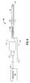
- FIG. 1is a schematic diagram of a microwave ablation system according to an embodiment of the present disclosure
- FIG. 2is a perspective view of a radiation detector according to one embodiment of the present disclosure
- FIGS. 3A-Bare top views of the radiation detector of FIG. 2 ;
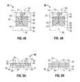
- FIGS. 4A-Bare bottom views of the radiation detector of FIG. 2 ;
- FIGS. 5A-Bare cross-sectional, side view of the radiation detector of FIG. 2 ;
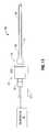
- FIG. 6is a schematic diagram of a microwave ablation system according to an embodiment of the present disclosure.
- FIG. 7is a perspective view of a radiation detector according to one embodiment of the present disclosure.
- FIGS. 8A-Bare top views of the radiation detector of FIG. 7 ;
- FIGS. 9A-Bare bottom views of the radiation detector of FIG. 7 ;
- FIGS. 10A-Bare cross-sectional, side view of the radiation detector of FIG. 7 ;
- FIG. 11is a schematic diagram of a microwave ablation system according to an embodiment of the present disclosure.
- FIG. 12is a perspective view of a radiation detector according to one embodiment of the present disclosure.
- FIG. 13is a top view of the radiation detector of FIG. 12 ;
- FIG. 14is a bottom view of the radiation detector of FIG. 12 ;
- FIG. 15is a perspective view of a radiation detector according to one embodiment of the present disclosure.
- FIG. 16is a top view of the radiation detector of FIG. 15 ;
- FIG. 17is a bottom view of the radiation detector of FIG. 15 ;
- FIG. 18is a flow chart of a method according to the present disclosure.
- the present disclosureprovides for a radiation detector disposed on a microwave antenna.
- the detectoris disposed in a location such that any unintended and/or errant radiation of microwave energy along the antenna is detected.
- the radiation detectorconverts the detected radiation into a detection signal, which is then transmitted to a control system (e.g., microwave generator) to either shut off the power supply and/or alert the user.
- a control systeme.g., microwave generator
- the radiation detectorincludes a receiving antenna adapted to receive microwave energy radiating along the microwave antenna and a rectifying circuit including a rectifying device and a filter.
- the rectifying circuitrectifies the microwave energy incident on the receiving antenna into a sensing signal and then passes the sensing signal through the filter to the control system.
- FIG. 1shows a microwave ablation system 10 that includes a microwave antenna assembly 12 coupled to a microwave generator 14 via a flexible coaxial cable 16 .
- the generator 14is configured to provide microwave energy at an operational frequency from about 500 MHz to about 10,000 MHz.
- the antenna assembly 12includes a radiating section 18 connected by feedline 20 (or shaft) to the cable 16 . More specifically, the feedline 20 is connected to a hub 22 , which is connected to the cable 16 through a cable connector 19 .
- the hub 22may have a variety of suitable shapes, e.g., cylindrical, rectangular, etc.
- the feedline 20may be coaxial and include an inner conductor surrounded by an inner insulator, which is, in turn, surrounded by an outer conductor 17 (e.g., a cylindrical conducting sheath).
- the inner conductor and outer conductor 17may be constructed of copper, gold, stainless steel or other conductive metals with similar conductivity values.
- the metalsmay be plated with other materials, e.g., other conductive materials, to improve their properties, e.g., to improve conductivity or decrease energy loss, etc.
- the feedline 20may be formed from a coaxial, semi-rigid or flexible cable having a wire with a 0.047′′ outer diameter rated for 50 Ohms.
- the antenna assembly 12includes a radiation detector 30 disposed proximally relative to the radiating section 18 , e.g., on the outer surface of the hub 22 .
- the radiation detector 30includes a so-called square “patch” receiving antenna 32 formed as a top antenna member 34 and a lower grounding member 35 .
- the antenna member 34is shaped as a square patch and is disposed on a top surface 40 of the substrate 36 as shown in FIGS. 2, 3 and 5 .
- the grounding member 35is formed as a border frame patch and is disposed on a bottom surface 41 of the substrate 36 as shown in FIGS. 2, 4 and 5 .
- the square shape of the receiving antenna 32allows the radiation detector 30 to act as a 360° receiver, allowing the radiation detector 30 to detect microwave radiation from any direction.
- each side of the receiving antenna 32may be substantially n ⁇ /4 of the wavelength of the microwave energy being supplied to the antenna 12 , where n is an integer, hence, the side may be ⁇ /4, ⁇ /2, ⁇ , etc.
- the substrate 36includes a top depression 38 on the top surface 40 thereof.
- the depression 38is dimensioned such that the antenna member 34 fits therein and that the antenna member 34 is substantially flush with the top surface 40 .
- the substrate 36also includes a bottom depression 39 on the bottom surface 41 thereof.
- the bottom depression 39is shaped as a border frame around the periphery of the substrate 36 .
- the depression 39is also dimensioned such that the grounding member 35 fits therein and the grounding member 35 is substantially flush with the bottom surface 41 .
- the top and bottom depressions 38 and 39may be formed a distance d from the perimeter of the substrate 36 , such that when disassembled, the antenna member 34 fits within the grounding member 35 .
- the substrate 36may have a planar top surface 40 and a planar bottom surface 41 with the antenna and grounding members 34 and 35 disposed thereon.
- the substrate 36may be formed from a non-conductive conformal material such as polyesters, polyimides, polyamides, polyamide-imides, polyetherimides, polyacrylates, polyethylene terephthalate, polyethylene, polypropylene, polyvinylidene chloride, polysiloxanes, combinations thereof and the like.
- the antenna and grounding members 34 and 35may be formed from a conformal sheet of conductive material such as copper, gold, stainless steel or other conductive metals with similar conductivity values.
- the receiving antenna 32may be plated with other materials, e.g., other conductive materials, to improve the conductive properties thereof.
- the conformal nature of the substrate 36 and the receiving antenna 32allows the radiation detector 30 to be disposed on the hub 22 of any suitable shape (e.g., cylindrical). Thus, the radiation detector 30 may be wrapped around the hub 22 .
- the radiation detector 30may also be encased in a shell 42 (e.g., epoxy) to provide for sterilization compatibility. The encasement may be accomplished once the radiation detector 30 is conformed to the hub 22 .
- the radiation detector 30also includes a rectifying circuit 50 including one or more rectifiers 52 ( FIGS. 2 and 3 ) and a filter 54 ( FIG. 4 ).
- the rectifiers 52are electrically coupled to the antenna member 34 .
- the rectifiers 52also include a shunt connection 56 passing through the substrate 36 to the grounding member 35 as best shown in FIG. 5 .
- the radiation detector 30includes a center tap feed 58 coupling the antenna member 34 to the grounding member 35 .
- the center tap feed 58passes through the substrate 36 in a similar manner as the shunt connections 56 .
- the center tap feed 58 and the shunt connections 56provide the only electrical connectivity between the antenna and grounding members 34 and 35 , which are otherwise electrically insulated by the substrate 36 .
- the center tap feed 58may be placed at a location of high current density and low electric field density to optimize DC current harvesting and minimize RF current disturbance.
- the center tap feed 58may be placed in a location of low RF impedance.
- Rectifiers 52are placed in locations of high electric field density and low current density.
- the rectifiers 52may be any type of suitable diodes such as Zener diode, Schottky diode, tunnel diode and the like.
- the rectifiers 52may be in direct contact with the antenna member 34 or through an impedance matching network, which may include lumped elements and/or a transmission line.
- the rectifiers 52may be disposed a predetermined distance/from the corner of the antenna member 34 ( FIGS. 3A-B ). The distance/may be varied to match the impedance of the rectifier 52 to the antenna assembly 12 .
- the rectifiers 52convert the sinusoidal shape of the microwave waveform by clipping the negative portion of the waveform. In other words, the rectifiers 52 clip the bottom portion of the sinusoid to rectify the microwave waveform.
- the filter 54is disposed at the bottom surface 41 and is electrically coupled to the center tap feed 58 .
- the filter 54may be an inductor-resistor-capacitor (“LRC”) low pass filter that is adapted to convert the rectified sinusoidal waveform from the rectifiers 52 into a detection signal, which may be a DC voltage signal representative of the detected microwave radiation.
- LRCinductor-resistor-capacitor
- the filter 54includes a capacitor 60 coupled between the center tap feed 58 and a first shunt connection 62 .
- the capacitor 60is connected in series with an inductor 64 , which is connected through a resistor 66 to a second shunt connection 68 as shown in FIG. 4A .
- the capacitor 60 , the inductor 64 and the resistor 66may be coupled to each other in parallel as shown in FIG. 4B .
- the inductor 64is coupled to the receiving antenna at the center tap feed 58 , which is now disposed at the edge of the antenna member 34 .
- the filter 54may be disposed on the top surface 40 and be coupled to antenna member 34 by the center tap feed 58 .
- the first and second shunt connections 62 and 68pass through the substrate 36 in a similar manner as the shunt connections 56 .
- the filter 54is also connected to a voltage output 70 that may be coupled to a wire 71 ( FIG. 1 ).
- the wire 71may be disposed anywhere along the antenna assembly 12 such that the wire 71 has minimal effect on the radiation efficiency of the antenna assembly 12 .
- the filter 54limits the microwave radiating from escaping through the wire 71 and allows the rectified DC current, namely, the detection signal to travel to the generator 14 .
- a ground wire(not explicitly shown) is coupled to the grounding member 35 and provides the generator 14 with a reference signal for comparison of the detection signal therewith.
- the detection signalmay then be transmitted to the generator 14 or another control system, which compares the detection signal with a reference threshold signal.
- the reference signalmay be preset to denote a threshold level indicative of dangerous levels of microwave radiation. If the generator 14 determines that the detection signal is above the reference signal, then the generator 14 may terminate or suspend the supply of energy to the antenna assembly 12 and/or alert the user.
- the generator 14may include any suitable type of alert or alarm (e.g., audio, visual, etc.) that is activated when the detection signal is above the threshold.
- the detection signalin addition to transmission of the detection signal to the generator 14 , the detection signal may also be used to power any suitable alarm device, such as a light-emitting device (e.g., LED 72 ) disposed on the bottom surface 41 .
- a light-emitting devicee.g., LED 72
- the LED 72may be configured to operate above a predetermined threshold voltage.
- an audible alarme.g., a speaker
- a speakermay be used in place of the LED 72 .
- the radiation detector 30may include a voltage limiting circuit 74 to ensure that the voltage level of the detection signal is regulated, such that, excessive voltage does not pass to the control circuitry of the generator 14 .
- the voltage limiting circuit 74may include a high impedance voltage buffer.
- FIGS. 6-10illustrate another embodiment of a radiation detector 130 .
- the radiation detector 130includes a linear receiving antenna 132 formed as a top antenna member 134 and a lower grounding member 135 .
- the antenna member 134is shaped as a rectangular patch and is disposed on a top surface 140 of the substrate 136 as shown in FIGS. 7-9 .
- the linear receiving antenna 132is disposed longitudinally on the antenna assembly 12 , such that the longitudinal axis of the receiving antenna 132 is substantially parallel with the longitudinal axis of the antenna assembly 12 . This configuration aligns the linear receiving antenna 132 with the emitted microwave energy.
- the grounding member 135may be formed as a border frame patch and is disposed on a bottom surface 141 of the substrate 136 as shown in FIGS. 7, 9 and 10 .
- the outer conductor 17may be used in lieu of the grounding member 135 , such that the substrate 136 is disposed on top of the outer conductor 17 .
- the substrate 136includes a top depression 138 on the top surface 40 thereof.
- the depression 138is dimensioned such that the antenna member 134 fits therein and resides substantially flush with the top surface 140 .
- the substrate 136will also be configured to include a bottom depression 139 on the bottom surface 141 thereof.
- the bottom depression 139is shaped as a border frame around the periphery of the substrate 36 .
- the depression 139is dimensioned such that the grounding member 135 fits therein in a substantially flush orientation relative to the bottom surface 141 .
- the substrate 136may have a planar top surface 140 and a planar bottom surface 141 with the antenna and grounding members 134 and 135 disposed thereon.
- the substrate 136may be formed from the same non-conductive conformal materials as the substrate 36 .
- the antenna and grounding members 134 and 135may be formed from any suitable conformal conductive materials similar to the materials of the antenna and grounding members 134 and 135 .
- the conformal nature of the substrate 136 and the receiving antenna 132allows the radiation detector 130 to be disposed around the shaft of the outer conductor 17 (e.g., wrapped longitudinally thereabout).
- the radiation detector 130also includes a rectifying circuit 150 including one or more rectifiers 152 and a filter 154 ( FIG. 9 ).
- the rectifiers 152are electrically coupled to the antenna member 134 and include a shunt connection 156 passing through the substrate 136 to the grounding member 135 as best shown in FIG. 10 .
- the radiation detector 130also includes a center tap feed 158 coupling the antenna member 134 to the grounding member 135 .
- the shunt connections and the center tap feed 158may shunt to the outer conductor 17 .
- the rectifiers 152may be disposed a predetermined distance/from center tap feed 158 ( FIGS. 8A-B ). The distance/may be varied to match the impedance of the rectifier 152 to the antenna assembly 12 .
- the filter 154is disposed at the bottom surface 141 and is electrically coupled to the center tap feed 158 .
- the filter 154is an LRC low pass filter that is adapted to convert the rectified sinusoidal waveform from the rectifiers 152 into a detection signal.
- the filter 154is also connected to a voltage output 170 which may be coupled to a wire 171 ( FIG. 6 ).
- a ground wire(not explicitly shown) is coupled to the grounding member 135 and provide the generator 14 with a reference signal for comparison of the detection signal therewith.
- the filter 154is coupled to the center tap feed 158 and first and second shunt connections 162 and 168 .
- the filter 154also includes a capacitor 160 , an inductor 164 and a resistor 166 coupled in series as shown in FIG. 9A .
- the capacitor 160 , the inductor 164 and the resistor 166may be coupled to each other in parallel as shown in FIG. 9B .
- the filter 154may be disposed on the top surface 140 and be coupled to antenna member 134 by the center tap feed 158 .
- the first and second shunt connections 162 and 168pass through the substrate 136 in a similar manner as the shunt connection 156 .
- the detection signalmay then be transmitted to the generator 14 or another control system, which compares the detection signal with a reference signal in the manner discussed above.
- the radiation detector 130also includes an LED 172 coupled to the voltage output 170 . The LED 172 lights up when the detection signal is above a predetermined threshold voltage.
- the radiation detector 130may also include a voltage limiting circuit 174 to ensure that excessive voltage does not pass to the control circuitry of the generator 14 .
- the present disclosureprovides for a radiation detector that allows for microwave ablation systems to recognize unintended radiation of microwave energy along the antenna assembly 12 toward the user. This is particularly useful for dielectrically buffered antennas that continue to radiate microwave energy efficiently, regardless of the radiating environment (e.g., inside or outside tissue).
- the radiation detector 30senses a high level of microwave radiating along the antenna assembly 12 and then transmits a detection signal to the generator 14 , which then registers the error and suspends the supply of power.
- FIGS. 11-14illustrate another embodiment of a radiation detector 230 .
- the radiation detector 230includes a circular receiving antenna 232 formed as a spiral antenna member 234 and a grounding member 235 .
- the circular receiving antenna 232includes an aperture 243 defined therethrough for insertion around the feedline 20 .
- the aperture 243allows the circular receiving antenna 232 to be disposed transversely with respect to a longitudinal axis defined by the antenna assembly 12 . This configuration aligns the circular receiving antenna 232 with the emitted microwave energy.
- the antenna member 234has a spiral shape and is disposed on a top surface 240 of a substrate 236 as shown in FIGS. 12 and 13 .
- the antenna member 234includes an inner end 280 coupled to the aperture 243 and an outside end 282 ( FIG. 13 ).
- the grounding member 235may be formed as a solid circular patch and is disposed on a bottom surface 241 of the substrate 236 as shown in FIGS. 12 and 14 .
- the substrate 236may be formed from the same non-conductive conformal materials as the substrate 36 .
- the antenna and grounding members 234 and 235may be formed from any suitable conformal conductive materials similar to the materials of the antenna and grounding members 34 and 35 .
- the radiation detector 230also includes a rectifying circuit 250 including one or more rectifiers 252 and a filter 254 .
- the rectifier 252is electrically coupled to the antenna member 234 and includes a shunt connection 256 passing through the substrate 236 to the grounding member 235 as shown in FIGS. 12 and 14 .
- the radiation detector 230also includes a center tap feed 258 ( FIG. 13 ).
- the center tap feed 258may be placed at a location of high current density and low electric field density to optimize DC current harvesting and minimize RF current disturbance, such as the outside end 282 . In other words, the center tap feed 258 may be placed in a location of low RF impedance.
- Rectifiers 252are placed in locations of high electric field density and low current density.
- the filter 254is disposed on the top surface 240 and is coupled to antenna member 234 by the center tap feed 258 .
- the filter 254is an LRC low pass filter that is adapted to convert the rectified sinusoidal waveform from the rectifiers 252 into a detection signal.
- the filter 254is also connected to a voltage output 270 which may be coupled to a wire 271 ( FIG. 11 ).
- a ground wire(not explicitly shown) is coupled to the grounding member 235 and provides the generator 14 with a reference signal for comparison of the detection signal.
- the filter 254is coupled to the center tap feed 258 and first and second shunt connections 262 and 268 .
- the filter 254also includes a capacitor 260 , an inductor 264 and a resistor 266 coupled in series.
- the capacitor 260 , the inductor 264 and the resistor 266may be coupled to each other in parallel.
- the first and second shunt connections 262 and 268pass through the substrate 236 in a similar manner as the center tap feed 258 .
- the detection signalmay then be transmitted to the generator 14 or another control system, which compares the detection signal with a reference signal in the manner discussed above.
- the radiation detector 230also includes an LED 272 coupled to the voltage output 270 . The LED 272 lights up when the detection signal is above a predetermined threshold voltage.
- the radiation detector 230may also include a voltage limiting circuit 274 to ensure that excessive voltage does not pass to the control circuitry of the generator 14 .
- FIGS. 15-17illustrate another embodiment of a radiation detector 230 which includes a circular receiving antenna 232 formed as a two top antenna members 234 a and 234 b and a lower grounding member 235 .
- the circular receiving antenna 232includes an aperture 243 defined therethrough for insertion around the feedline 20 .
- the aperture 243allows the circular receiving antenna 232 to be disposed transversely with respect to a longitudinal axis defined by the antenna assembly 12 . This configuration aligns the circular receiving antenna 232 with the emitted microwave energy.
- the antenna members 234 a and 234 bhave a spiral shape and are disposed on a top surface 240 of the substrate 236 as shown in FIGS. 15 and 16 .
- Each of the antenna members 234 a and 234 bincludes an inner end 280 coupled to the aperture 243 and an outside end 282 .
- the grounding member 235may be formed as a solid circular patch and is disposed on a bottom surface 241 of the substrate 236 as shown in FIGS. 16 and 17 .
- the substrate 236may be formed from the same non-conductive conformal materials as the substrate 36 .
- the antenna members 234 a and 234 b and grounding member 235may be formed from any suitable conformal conductive materials similar to the materials of the antenna and grounding members 34 and 35 .
- the radiation detector 230also includes a rectifying circuit 250 including one or more rectifiers 252 and filters 254 .
- the rectifier 252electrically couples the antenna members 234 a and 234 at the inner ends 280 . This location coincides with high electric field density and low current density.
- the radiation detector 230also includes center tap feeds 258 a and 258 b ( FIG. 16 ).
- the center tap feeds 258 a and 258 bmay be placed at a location of high current density and low electric field density to optimize DC current harvesting and minimize RF current disturbance, such as the outside end 282 of the antenna member 234 .
- the center tap feeds 258 a and 258 bmay be placed in a location of low RF impedance.
- the filters 254are disposed on the top surface 240 and are coupled to antenna members 234 a and 234 b , respectively, at the center tap feeds 258 a and 258 b .
- the filters 254are LRC low pass filters adapted to convert the rectified sinusoidal waveform from the rectifier 252 into a detection signal.
- the filters 254are also connected to respective voltage outputs 270 which may be coupled to the wire 271 ( FIG. 11 ).
- the signals from the filters 254provide the generator 14 with detection signals, which the generator 14 then processes to determine the amount of radiation.
- Each of the filters 254is coupled to first and second shunt connections 262 and 268 .
- Each of the filters 254also includes a capacitor 260 , an inductor 264 and a resistor 266 coupled in series. In another embodiment, the capacitor 260 , the inductor 264 and the resistor 266 may be coupled to each other in parallel.
- the first and second shunt connections 262 and 268pass through the substrate 236 in a similar manner as the shunt connection 256 .
- the radiation detector 230also includes an LED 272 coupled to the voltage output 270 of each of the filters 254 .
- the LEDs 272light up when the detection signal is above a predetermined threshold voltage.
- the radiation detector 230may also include a voltage limiting circuit 274 coupled to each of the filters 254 to ensure that excessive voltage does not pass to the control circuitry of the generator 14 .
- FIG. 18shows a method for detecting errant microwave energy outside the radiating section 18 .
- the method of the present disclosureis described with reference to the radiation detector 30 . It should be appreciated that the method may be practiced with other radiation detectors, such as the radiation detectors 130 , 230 and the like.
- the methodincludes an initial step of providing the radiating detector 30 on the microwave antenna assembly 12 which includes wrapping the radiating section 30 on the hub 22 .
- the methodmay also include the step of connecting the radiation detector 30 to the generator 14 or another control system.
- any errant microwave radiation outside the desired emission areais picked up by the receiving antenna 32 , namely, the antenna member 34 .
- the detected microwave energyis then rectified by the rectifiers 52 and the rectified signal is filtered by the filter 54 into a detection signal (e.g., a DC voltage signal).
- the detection signalis then used to light up the LED 72 and/or is transmitted to generator 14 .
- the generator 14compares the detection signal to a threshold value to determine whether the level of the microwave energy is unsafe. If the determination is made that the level of microwave energy is excessive, the generator 14 may either suspend the supply of microwave energy and/or alert the user of this occurrence.
Landscapes
- Health & Medical Sciences (AREA)
- Physics & Mathematics (AREA)
- Life Sciences & Earth Sciences (AREA)
- Surgery (AREA)
- Engineering & Computer Science (AREA)
- General Health & Medical Sciences (AREA)
- Electromagnetism (AREA)
- General Physics & Mathematics (AREA)
- Veterinary Medicine (AREA)
- Nuclear Medicine, Radiotherapy & Molecular Imaging (AREA)
- Heart & Thoracic Surgery (AREA)
- Medical Informatics (AREA)
- Molecular Biology (AREA)
- Animal Behavior & Ethology (AREA)
- Public Health (AREA)
- Otolaryngology (AREA)
- Biomedical Technology (AREA)
- Cardiology (AREA)
- Plasma & Fusion (AREA)
- Power Engineering (AREA)
- Chemical & Material Sciences (AREA)
- Analytical Chemistry (AREA)
- Biochemistry (AREA)
- Immunology (AREA)
- Pathology (AREA)
- Surgical Instruments (AREA)
- Waveguide Aerials (AREA)
- Details Of Aerials (AREA)
Abstract
Description
Claims (11)
Priority Applications (1)
| Application Number | Priority Date | Filing Date | Title |
|---|---|---|---|
| US14/499,937US9625395B2 (en) | 2009-06-19 | 2014-09-29 | Microwave ablation antenna radiation detector |
Applications Claiming Priority (3)
| Application Number | Priority Date | Filing Date | Title |
|---|---|---|---|
| US12/487,917US8552915B2 (en) | 2009-06-19 | 2009-06-19 | Microwave ablation antenna radiation detector |
| US14/048,835US8847830B2 (en) | 2009-06-19 | 2013-10-08 | Microwave ablation antenna radiation detector |
| US14/499,937US9625395B2 (en) | 2009-06-19 | 2014-09-29 | Microwave ablation antenna radiation detector |
Related Parent Applications (1)
| Application Number | Title | Priority Date | Filing Date |
|---|---|---|---|
| US14/048,835ContinuationUS8847830B2 (en) | 2009-06-19 | 2013-10-08 | Microwave ablation antenna radiation detector |
Publications (2)
| Publication Number | Publication Date |
|---|---|
| US20150015237A1 US20150015237A1 (en) | 2015-01-15 |
| US9625395B2true US9625395B2 (en) | 2017-04-18 |
Family
ID=42741835
Family Applications (3)
| Application Number | Title | Priority Date | Filing Date |
|---|---|---|---|
| US12/487,917Active2032-08-08US8552915B2 (en) | 2009-06-19 | 2009-06-19 | Microwave ablation antenna radiation detector |
| US14/048,835ActiveUS8847830B2 (en) | 2009-06-19 | 2013-10-08 | Microwave ablation antenna radiation detector |
| US14/499,937Expired - Fee RelatedUS9625395B2 (en) | 2009-06-19 | 2014-09-29 | Microwave ablation antenna radiation detector |
Family Applications Before (2)
| Application Number | Title | Priority Date | Filing Date |
|---|---|---|---|
| US12/487,917Active2032-08-08US8552915B2 (en) | 2009-06-19 | 2009-06-19 | Microwave ablation antenna radiation detector |
| US14/048,835ActiveUS8847830B2 (en) | 2009-06-19 | 2013-10-08 | Microwave ablation antenna radiation detector |
Country Status (3)
| Country | Link |
|---|---|
| US (3) | US8552915B2 (en) |
| EP (1) | EP2264828B1 (en) |
| JP (2) | JP5815927B2 (en) |
Cited By (1)
| Publication number | Priority date | Publication date | Assignee | Title |
|---|---|---|---|---|
| US10652832B1 (en) | 2019-05-30 | 2020-05-12 | Microsoft Technology Licensing, Llc | Systems and methods to adjust transmission power in electronic devices |
Families Citing this family (38)
| Publication number | Priority date | Publication date | Assignee | Title |
|---|---|---|---|---|
| US7553309B2 (en) | 2004-10-08 | 2009-06-30 | Covidien Ag | Electrosurgical system employing multiple electrodes and method thereof |
| US8486127B2 (en)* | 2006-05-24 | 2013-07-16 | Kambiz Dowlatshahi | High temperature thermal therapy of breast cancer |
| US8552915B2 (en) | 2009-06-19 | 2013-10-08 | Covidien Lp | Microwave ablation antenna radiation detector |
| US8323275B2 (en) | 2009-06-19 | 2012-12-04 | Vivant Medical, Inc. | Laparoscopic port with microwave rectifier |
| US9113925B2 (en)* | 2009-09-09 | 2015-08-25 | Covidien Lp | System and method for performing an ablation procedure |
| US8069553B2 (en) | 2009-09-09 | 2011-12-06 | Vivant Medical, Inc. | Method for constructing a dipole antenna |
| US9095359B2 (en) | 2009-09-18 | 2015-08-04 | Covidien Lp | Tissue ablation system with energy distribution |
| US9113926B2 (en) | 2009-09-29 | 2015-08-25 | Covidien Lp | Management of voltage standing wave ratio at skin surface during microwave ablation |
| US8568398B2 (en) | 2009-09-29 | 2013-10-29 | Covidien Lp | Flow rate monitor for fluid cooled microwave ablation probe |
| US8568401B2 (en) | 2009-10-27 | 2013-10-29 | Covidien Lp | System for monitoring ablation size |
| US8382750B2 (en)* | 2009-10-28 | 2013-02-26 | Vivant Medical, Inc. | System and method for monitoring ablation size |
| US8430871B2 (en) | 2009-10-28 | 2013-04-30 | Covidien Lp | System and method for monitoring ablation size |
| US8394092B2 (en)* | 2009-11-17 | 2013-03-12 | Vivant Medical, Inc. | Electromagnetic energy delivery devices including an energy applicator array and electrosurgical systems including same |
| US8764744B2 (en) | 2010-01-25 | 2014-07-01 | Covidien Lp | System for monitoring ablation size |
| US8491579B2 (en) | 2010-02-05 | 2013-07-23 | Covidien Lp | Electrosurgical devices with choke shorted to biological tissue |
| US8968288B2 (en) | 2010-02-19 | 2015-03-03 | Covidien Lp | Ablation devices with dual operating frequencies, systems including same, and methods of adjusting ablation volume using same |
| US8617153B2 (en) | 2010-02-26 | 2013-12-31 | Covidien Lp | Tunable microwave ablation probe |
| US8728067B2 (en) | 2010-03-08 | 2014-05-20 | Covidien Lp | Microwave antenna probe having a deployable ground plane |
| US10039601B2 (en) | 2010-03-26 | 2018-08-07 | Covidien Lp | Ablation devices with adjustable radiating section lengths, electrosurgical systems including same, and methods of adjusting ablation fields using same |
| US8409188B2 (en) | 2010-03-26 | 2013-04-02 | Covidien Lp | Ablation devices with adjustable radiating section lengths, electrosurgical systems including same, and methods of adjusting ablation fields using same |
| US9192436B2 (en) | 2010-05-25 | 2015-11-24 | Covidien Lp | Flow rate verification monitor for fluid-cooled microwave ablation probe |
| US8652127B2 (en) | 2010-05-26 | 2014-02-18 | Covidien Lp | System and method for chemically cooling an ablation antenna |
| US9241762B2 (en) | 2010-06-03 | 2016-01-26 | Covidien Lp | Specific absorption rate measurement and energy-delivery device characterization using image analysis |
| US8672933B2 (en) | 2010-06-30 | 2014-03-18 | Covidien Lp | Microwave antenna having a reactively-loaded loop configuration |
| US10588684B2 (en) | 2010-07-19 | 2020-03-17 | Covidien Lp | Hydraulic conductivity monitoring to initiate tissue division |
| US9055957B2 (en) | 2010-12-23 | 2015-06-16 | Covidien Lp | Microwave field-detecting needle assemblies, methods of manufacturing same, methods of adjusting an ablation field radiating into tissue using same, and systems including same |
| US9028476B2 (en) | 2011-02-03 | 2015-05-12 | Covidien Lp | Dual antenna microwave resection and ablation device, system and method of use |
| JP2012236021A (en)* | 2011-05-10 | 2012-12-06 | Vivant Medical Inc | Laparoscopic port with microwave rectifier |
| US8876813B2 (en) | 2013-03-14 | 2014-11-04 | St. Jude Medical, Inc. | Methods, systems, and apparatus for neural signal detection |
| AU2015374244B2 (en) | 2014-12-31 | 2019-11-21 | Covidien Lp | System and method for treating COPD and emphysema |
| US10231770B2 (en)* | 2015-01-09 | 2019-03-19 | Medtronic Holding Company Sárl | Tumor ablation system |
| CN105336757B (en)* | 2015-11-06 | 2018-05-15 | 中国计量学院 | Flexible microwave energy converter based on organic diode |
| US10265111B2 (en) | 2016-04-26 | 2019-04-23 | Medtronic Holding Company Sárl | Inflatable bone tamp with flow control and methods of use |
| US10698015B2 (en)* | 2017-10-11 | 2020-06-30 | Rey Dandy Provido Lachica | Systems and methods to facilitate detecting an electromagnetic radiation in a space by using a self-powered radio frequency device (SP-RF device) |
| US11484355B2 (en) | 2020-03-02 | 2022-11-01 | Medtronic Holding Company Sàrl | Inflatable bone tamp and method for use of inflatable bone tamp |
| TWI773132B (en)* | 2021-02-08 | 2022-08-01 | 國立臺灣大學 | Movable compact-range antenna measurement system |
| CN113588305B (en)* | 2021-07-13 | 2022-03-29 | 华中科技大学 | Device for microwave-assisted steady-state premixed combustion research |
| CN115494084A (en)* | 2022-09-02 | 2022-12-20 | 南京理工大学 | High voltage cable icing monitoring method based on millimeter wave |
Citations (206)
| Publication number | Priority date | Publication date | Assignee | Title |
|---|---|---|---|---|
| SU166452A1 (en) | В. А. Костров , Л. В. Смирнов | STOMATOLOGICAL DIATHERMOKOAGULATOR | ||
| DE390937C (en) | 1922-10-13 | 1924-03-03 | Adolf Erb | Device for internal heating of furnace furnaces for hardening, tempering, annealing, quenching and melting |
| DE1099658B (en) | 1959-04-29 | 1961-02-16 | Siemens Reiniger Werke Ag | Automatic switch-on device for high-frequency surgical devices |
| FR1275415A (en) | 1960-09-26 | 1961-11-10 | Device for detecting disturbances for electrical installations, in particular electrosurgery | |
| DE1139927B (en) | 1961-01-03 | 1962-11-22 | Friedrich Laber | High-frequency surgical device |
| DE1149832B (en) | 1961-02-25 | 1963-06-06 | Siemens Reiniger Werke Ag | High frequency surgical apparatus |
| FR1347865A (en) | 1962-11-22 | 1964-01-04 | Improvements to diathermo-coagulation devices | |
| DE1439302A1 (en) | 1963-10-26 | 1969-01-23 | Siemens Ag | High-frequency surgical device |
| US3631363A (en) | 1969-11-14 | 1971-12-28 | Gen Electric | High-frequency cavity oscillator having improved tuning means |
| SU401367A1 (en) | 1971-10-05 | 1973-10-12 | Тернопольский государственный медицинский институт | BIAKTIVNYE ELECTRO SURGICAL INSTRUMENT |
| FR2235669A1 (en) | 1973-07-07 | 1975-01-31 | Lunacek Boris | Gynaecological sterilisation instrument - has hollow electrode protruding from the end of a curved ended tube |
| DE2439587A1 (en) | 1973-08-23 | 1975-02-27 | Matburn Holdings Ltd | ELECTROSURGICAL DEVICE |
| DE2455174A1 (en) | 1973-11-21 | 1975-05-22 | Termiflex Corp | INPUT / OUTPUT DEVICE FOR DATA EXCHANGE WITH DATA PROCESSING DEVICES |
| DE2407559A1 (en) | 1974-02-16 | 1975-08-28 | Dornier System Gmbh | Tissue heat treatment probe - has water cooling system which ensures heat development only in treated tissues |
| DE2415263A1 (en) | 1974-03-29 | 1975-10-02 | Aesculap Werke Ag | Surgical H.F. coagulation probe has electrode tongs - with exposed ends of insulated conductors forming tong-jaws |
| DE2429021A1 (en) | 1974-06-18 | 1976-01-08 | Erbe Elektromedizin | Remote control for HF surgical instruments - uses cable with two conductors at most |
| FR2276027A1 (en) | 1974-06-25 | 1976-01-23 | Medical Plastics Inc | Plate electrode with connector - is clamped between connector jaws held by releasable locking device |
| DE2460481A1 (en) | 1974-12-20 | 1976-06-24 | Delma Elektro Med App | Electrode grip for remote HF surgical instrument switching - has shaped insulated piece with contact ring of sterilizable (silicon) rubber |
| DE2602517A1 (en) | 1975-01-23 | 1976-07-29 | Dentsply Int Inc | ELECTROSURGICAL DEVICE |
| DE2504280A1 (en) | 1975-02-01 | 1976-08-05 | Hans Heinrich Prof Dr Meinke | DEVICE FOR ELECTRIC TISSUE CUTTING IN SURGERY |
| FR2313708A1 (en) | 1975-06-02 | 1976-12-31 | Sybron Corp | Electro surgical instrument impulse control circuit - has potentiometer between patient electrodes and threshold switch for excessive voltage |
| DE2627679A1 (en) | 1975-06-26 | 1977-01-13 | Marcel Lamidey | HEMATISTIC HIGH FREQUENCY EXTRACTOR FORCEPS |
| DE2540968A1 (en) | 1975-09-13 | 1977-03-17 | Erbe Elektromedizin | Circuit for bipolar coagulation tweezers - permits preparation of tissues prior to coagulation |
| DE2820908A1 (en) | 1977-05-16 | 1978-11-23 | Joseph Skovajsa | DEVICE FOR THE LOCAL TREATMENT OF A PATIENT IN PARTICULAR FOR ACUPUNCTURE OR AURICULAR THERAPY |
| DE2803275A1 (en) | 1978-01-26 | 1979-08-02 | Aesculap Werke Ag | HF surgical appts. with active treatment and patient electrodes - has sensor switching generator to small voltage when hand-operated switch is closed |
| DE2823291A1 (en) | 1978-05-27 | 1979-11-29 | Rainer Ing Grad Koch | Coagulation instrument automatic HF switching circuit - has first lead to potentiometer and second to transistor base |
| SU727201A2 (en) | 1977-11-02 | 1980-04-15 | Киевский Научно-Исследовательский Институт Нейрохирургии | Electric surgical apparatus |
| US4215275A (en) | 1977-12-07 | 1980-07-29 | Luxtron Corporation | Optical temperature measurement technique utilizing phosphors |
| DE2946728A1 (en) | 1979-11-20 | 1981-05-27 | Erbe Elektromedizin GmbH & Co KG, 7400 Tübingen | HF surgical appts. for use with endoscope - provides cutting or coagulation current at preset intervals and of selected duration |
| USD263020S (en) | 1980-01-22 | 1982-02-16 | Rau Iii David M | Retractable knife |
| DE3143421A1 (en) | 1980-11-04 | 1982-05-27 | The Agency of Industrial Science and Technology, Tokyo | Laser scalpel |
| DE3045996A1 (en) | 1980-12-05 | 1982-07-08 | Medic Eschmann Handelsgesellschaft für medizinische Instrumente mbH, 2000 Hamburg | Electro-surgical scalpel instrument - has power supply remotely controlled by surgeon |
| FR2502935A1 (en) | 1981-03-31 | 1982-10-08 | Dolley Roger | Diathermic knife for coagulating tissues - has monitoring current added to HF coagulating current in order to control end of operation as function or resistance of coagulating tissues |
| USD266842S (en) | 1980-06-27 | 1982-11-09 | Villers Mark W | Phonograph record spacer |
| DE3120102A1 (en) | 1981-05-20 | 1982-12-09 | F.L. Fischer GmbH & Co, 7800 Freiburg | ARRANGEMENT FOR HIGH-FREQUENCY COAGULATION OF EGG WHITE FOR SURGICAL PURPOSES |
| FR2517953A1 (en) | 1981-12-10 | 1983-06-17 | Alvar Electronic | Diaphanometer for optical examination of breast tissue structure - measures tissue transparency using two plates and optical fibre bundle cooperating with photoelectric cells |
| US4397313A (en) | 1981-08-03 | 1983-08-09 | Clini-Therm Corporation | Multiple microwave applicator system and method for microwave hyperthermia treatment |
| US4462412A (en) | 1980-04-02 | 1984-07-31 | Bsd Medical Corporation | Annular electromagnetic radiation applicator for biological tissue, and method |
| USD278306S (en) | 1980-06-30 | 1985-04-09 | Mcintosh Lois A | Microwave oven rack |
| US4539567A (en) | 1983-09-12 | 1985-09-03 | Micrometrics, Ltd. | Microwave monitor |
| US4572190A (en) | 1983-05-26 | 1986-02-25 | Cgr/Mev | Hyperthermia apparatus |
| US4580557A (en) | 1983-08-22 | 1986-04-08 | Laserscope | Surgical laser system with multiple output devices |
| FR2573301A1 (en) | 1984-11-16 | 1986-05-23 | Lamidey Gilles | Surgical forceps and its control and monitoring apparatus |
| DE3510586A1 (en) | 1985-03-23 | 1986-10-02 | Erbe Elektromedizin GmbH, 7400 Tübingen | Control device for a high-frequency surgical instrument |
| DE3604823A1 (en) | 1986-02-15 | 1987-08-27 | Flachenecker Gerhard | HIGH FREQUENCY GENERATOR WITH AUTOMATIC PERFORMANCE CONTROL FOR HIGH FREQUENCY SURGERY |
| EP0246350A1 (en) | 1986-05-23 | 1987-11-25 | Erbe Elektromedizin GmbH. | Coagulation electrode |
| DE8712328U1 (en) | 1987-09-11 | 1988-02-18 | Jakoubek, Franz, 7201 Emmingen-Liptingen | Endoscopy forceps |
| USD295893S (en) | 1985-09-25 | 1988-05-24 | Acme United Corporation | Disposable surgical clamp |
| USD295894S (en) | 1985-09-26 | 1988-05-24 | Acme United Corporation | Disposable surgical scissors |
| US4753248A (en) | 1987-06-24 | 1988-06-28 | Duke University | Probe translation system for use in hyperthermia treatment |
| DE3711511C1 (en) | 1987-04-04 | 1988-06-30 | Hartmann & Braun Ag | Method for determining gas concentrations in a gas mixture and sensor for measuring thermal conductivity |
| US4798215A (en) | 1984-03-15 | 1989-01-17 | Bsd Medical Corporation | Hyperthermia apparatus |
| DE3904558A1 (en) | 1989-02-15 | 1990-08-23 | Flachenecker Gerhard | Radio-frequency generator with automatic power control for radio-frequency surgery |
| DE3942998A1 (en) | 1989-12-27 | 1991-07-04 | Delma Elektro Med App | Electro-surgical HF instrument for contact coagulation - has monitoring circuit evaluating HF voltage at electrodes and delivering switch=off signal |
| US5097844A (en) | 1980-04-02 | 1992-03-24 | Bsd Medical Corporation | Hyperthermia apparatus having three-dimensional focusing |
| EP0481685A1 (en) | 1990-10-15 | 1992-04-22 | Cook Incorporated | Medical device for localizing a lesion |
| EP0521264A2 (en) | 1991-07-03 | 1993-01-07 | W.L. Gore & Associates GmbH | Antenna device with feed |
| JPH055106A (en) | 1990-07-31 | 1993-01-14 | Matsushita Electric Works Ltd | Production of alloy sintered body |
| JPH0540112A (en) | 1991-02-08 | 1993-02-19 | Tokico Ltd | Sample liquid component analyzer |
| DE4238263A1 (en) | 1991-11-15 | 1993-05-19 | Minnesota Mining & Mfg | Adhesive comprising hydrogel and crosslinked polyvinyl:lactam - is used in electrodes for biomedical application providing low impedance and good mechanical properties when water and/or moisture is absorbed from skin |
| EP0556705A1 (en) | 1992-02-20 | 1993-08-25 | DELMA ELEKTRO-UND MEDIZINISCHE APPARATEBAU GESELLSCHAFT mbH | High frequency surgery device |
| EP0558429A1 (en) | 1992-02-26 | 1993-09-01 | PECHINEY RECHERCHE (Groupement d'Intérêt Economique géré par l'ordonnance no. 67-821 du 23 Septembre 1967) | Method of simultaneous measuring of electrical resistivety and thermal conductivity |
| EP0572131A1 (en) | 1992-05-21 | 1993-12-01 | Everest Medical Corporation | Surgical scissors with bipolar coagulation feature |
| US5350391A (en) | 1992-10-19 | 1994-09-27 | Benedetto Iacovelli | Laparoscopic instruments |
| JPH06343644A (en) | 1993-05-04 | 1994-12-20 | Gyrus Medical Ltd | Surgical peritoneoscope equipment |
| US5375596A (en)* | 1992-09-29 | 1994-12-27 | Hdc Corporation | Method and apparatus for determining the position of catheters, tubes, placement guidewires and implantable ports within biological tissue |
| USD354218S (en) | 1992-10-01 | 1995-01-10 | Fiberslab Pty Limited | Spacer for use in concrete construction |
| DE4303882C2 (en) | 1993-02-10 | 1995-02-09 | Kernforschungsz Karlsruhe | Combination instrument for separation and coagulation for minimally invasive surgery |
| EP0648515A1 (en) | 1993-10-15 | 1995-04-19 | SADIS BRUKER SPECTROSPIN, SOCIETE ANONYME DE DIFFUSION DE L'INSTRUMENTATION SCIENTIFIQUE BRUKER SPECTROSPIN (S.A. à Direct.) | Antenna for microwave heating of tissue and catheter with one or more antennas |
| DE4339049A1 (en) | 1993-11-16 | 1995-05-18 | Erbe Elektromedizin | Surgical system and instruments configuration device |
| US5417210A (en) | 1992-05-27 | 1995-05-23 | International Business Machines Corporation | System and method for augmentation of endoscopic surgery |
| CN1103807A (en) | 1993-11-17 | 1995-06-21 | 刘中一 | Multi-frequency micro-wave therapeutic instrument |
| US5429133A (en) | 1992-12-18 | 1995-07-04 | Neoprobe Corporation | Radiation responsive laparoscopic instrument |
| JPH07185019A (en) | 1993-12-27 | 1995-07-25 | Olympus Optical Co Ltd | Thermotherapeutic device |
| JPH07265328A (en) | 1993-11-01 | 1995-10-17 | Gyrus Medical Ltd | Electrode assembly for electric surgery device and electric surgery device using it |
| JPH0856955A (en) | 1994-06-29 | 1996-03-05 | Gyrus Medical Ltd | Electric surgical apparatus |
| JPH08252263A (en) | 1994-12-21 | 1996-10-01 | Gyrus Medical Ltd | Electronic surgical incision instrument and electronic surgical incision device using the same |
| DE29616210U1 (en) | 1996-09-18 | 1996-11-14 | Olympus Winter & Ibe Gmbh, 22045 Hamburg | Handle for surgical instruments |
| JPH09492A (en) | 1995-06-21 | 1997-01-07 | Olympus Optical Co Ltd | Treatment tool inserting and detaching device for endoscope |
| JPH0910223A (en) | 1995-06-23 | 1997-01-14 | Gyrus Medical Ltd | Generator and system for electric operation |
| DE19608716C1 (en) | 1996-03-06 | 1997-04-17 | Aesculap Ag | Bipolar surgical holding instrument |
| JPH09164215A (en) | 1995-12-15 | 1997-06-24 | Olympus Optical Co Ltd | Microwave antenna |
| US5671133A (en) | 1994-02-10 | 1997-09-23 | Matsushita Electrical Industrial Co., Ltd. | Electric power receiving and supplying circuit |
| WO1997041924A1 (en) | 1996-05-06 | 1997-11-13 | Thermal Therapeutics, Inc. | Transcervical intrauterine applicator for intrauterine hyperthermia |
| WO1997043971A2 (en) | 1996-05-22 | 1997-11-27 | Somnus Medical Technologies, Inc. | Method and apparatus for ablating turbinates |
| EP0541930B1 (en) | 1991-10-17 | 1998-03-25 | Smith & Nephew, Inc. | Transmission link for use in surgical instruments |
| JPH1099455A (en) | 1996-09-26 | 1998-04-21 | Olympus Optical Co Ltd | Therapeutic device with heating |
| EP0836868A2 (en) | 1996-10-18 | 1998-04-22 | Gebr. Berchtold GmbH & Co. | High frequency surgical apparatus and method for operating same |
| DE19751106A1 (en) | 1996-11-27 | 1998-05-28 | Eastman Kodak Co | Laser printer with array of laser diodes |
| DE19717411A1 (en) | 1997-04-25 | 1998-11-05 | Aesculap Ag & Co Kg | Monitoring of thermal loading of patient tissue in contact region of neutral electrode of HF treatment unit |
| EP0882955A1 (en) | 1997-06-06 | 1998-12-09 | Endress + Hauser GmbH + Co. | Level measuring apparatus using microwaves |
| DE19751108A1 (en) | 1997-11-18 | 1999-05-20 | Beger Frank Michael Dipl Desig | Electrosurgical operation tool, especially for diathermy |
| WO1999025248A1 (en) | 1997-11-18 | 1999-05-27 | Care Wise Medical Products Corporation | Minimally invasive surgical probe for tissue identification and retrieval and method of use |
| DE19801173C1 (en) | 1998-01-15 | 1999-07-15 | Kendall Med Erzeugnisse Gmbh | Clamp connector for film electrodes |
| JPH11244298A (en) | 1997-12-19 | 1999-09-14 | Gyrus Medical Ltd | Electric surgical instrument |
| US6031375A (en) | 1997-11-26 | 2000-02-29 | The Johns Hopkins University | Method of magnetic resonance analysis employing cylindrical coordinates and an associated apparatus |
| USD424694S (en) | 1998-10-23 | 2000-05-09 | Sherwood Services Ag | Forceps |
| USD424693S (en) | 1999-04-08 | 2000-05-09 | Pruter Rick L | Needle guide for attachment to an ultrasound transducer probe |
| USD425201S (en) | 1998-10-23 | 2000-05-16 | Sherwood Services Ag | Disposable electrode assembly |
| DE19848540A1 (en) | 1998-10-21 | 2000-05-25 | Reinhard Kalfhaus | Circuit layout and method for operating a single- or multiphase current inverter connects an AC voltage output to a primary winding and current and a working resistance to a transformer's secondary winding and current. |
| WO2000036985A2 (en) | 1998-12-18 | 2000-06-29 | Celon Ag Medical Instruments | Electrode assembly for a surgical instrument provided for carrying out an electrothermal coagulation of tissue |
| WO2000048672A1 (en) | 1999-02-19 | 2000-08-24 | Knowlton Edward W | Stomach treatment apparatus and method |
| WO2000051513A1 (en) | 1999-03-05 | 2000-09-08 | Plc Medical Systems, Inc. | Energy delivery system and method for performing myocardial revascularization |
| JP2000324840A (en) | 1999-03-24 | 2000-11-24 | Rohde & Schwarz Gmbh & Co Kg | Half-wave or a plurality of high-frequency diode rectifier circuit |
| JP2000342599A (en) | 1999-05-21 | 2000-12-12 | Gyrus Medical Ltd | Generator for electrosurgical operation, electrosurgical operation system, method for operating this system and method for performing amputation and resection of tissue by electrosurgical operation |
| JP2000350732A (en) | 1999-05-21 | 2000-12-19 | Gyrus Medical Ltd | Electrosurgical system, generator for electrosurgery, and method for cutting or excising tissue by electrosurgery |
| JP2001003776A (en) | 1999-06-22 | 2001-01-09 | Mitsubishi Electric Corp | Automatic transmission control device |
| WO2001001847A1 (en) | 1999-07-06 | 2001-01-11 | Inbae Yoon | Penetrating endoscope and endoscopic surgical instrument with cmos image sensor and display |
| JP2001008944A (en) | 1999-05-28 | 2001-01-16 | Gyrus Medical Ltd | Electric surgical signal generator and electric surgical system |
| JP2001029356A (en) | 1999-06-11 | 2001-02-06 | Gyrus Medical Ltd | Electric and surgical signal generator |
| JP2001037775A (en) | 1999-07-26 | 2001-02-13 | Olympus Optical Co Ltd | Treatment device |
| US6222193B1 (en) | 1998-10-06 | 2001-04-24 | Neoprobe Corporation | Radiation responsive surgical probe apparatus |
| JP2001128990A (en) | 1999-05-28 | 2001-05-15 | Gyrus Medical Ltd | Electro surgical instrument and electrosurgical tool converter |
| JP2001231870A (en) | 2000-02-23 | 2001-08-28 | Olympus Optical Co Ltd | Moisturizing treatment apparatus |
| WO2001074252A2 (en) | 2000-03-31 | 2001-10-11 | Rita Medical Systems Inc. | Tissue biopsy and treatment apparatus and method |
| USD449886S1 (en) | 1998-10-23 | 2001-10-30 | Sherwood Services Ag | Forceps with disposable electrode |
| EP1159926A2 (en) | 2000-06-03 | 2001-12-05 | Aesculap Ag | Scissor- or forceps-like surgical instrument |
| US6332089B1 (en) | 1996-02-15 | 2001-12-18 | Biosense, Inc. | Medical procedures and apparatus using intrabody probes |
| US20020022836A1 (en) | 1999-03-05 | 2002-02-21 | Gyrus Medical Limited | Electrosurgery system |
| US6375606B1 (en) | 1999-03-17 | 2002-04-23 | Stereotaxis, Inc. | Methods of and apparatus for treating vascular defects |
| USD457959S1 (en) | 2001-04-06 | 2002-05-28 | Sherwood Services Ag | Vessel sealer |
| USD457958S1 (en) | 2001-04-06 | 2002-05-28 | Sherwood Services Ag | Vessel sealer and divider |
| WO2002045790A2 (en) | 2000-12-08 | 2002-06-13 | Medtronic Ave, Inc. | Hyperthermia radiation apparatus and method for treatment of malignant tumors |
| US20020075189A1 (en)* | 2000-12-18 | 2002-06-20 | Carillo Juan C. | Close-proximity radiation detection device for determining radiation shielding device effectiveness and a method therefor |
| US20020087079A1 (en) | 2001-01-03 | 2002-07-04 | Leon Kaufman | Position sensitive catheter having scintillation detectors |
| US6424869B1 (en) | 1995-09-06 | 2002-07-23 | Meridian Medical Systems, Llc | Dual mode transurethral microwave warming apparatus |
| WO2002061880A2 (en) | 2001-01-31 | 2002-08-08 | Cnr Consiglio Nazionale Delle Ricerche | Interstitial microwave antenna with miniaturized choke for hyperthermia and surgery |
| EP1278007A1 (en) | 2001-07-18 | 2003-01-22 | Lumitex, Inc. | Light delivery systems and applications thereof |
| US6603994B2 (en) | 2000-12-28 | 2003-08-05 | Scimed Life Systems, Inc. | Apparatus and method for internally inducing a magnetic field in an aneurysm to embolize aneurysm with magnetically-controllable substance |
| DE10224154A1 (en) | 2002-05-27 | 2003-12-18 | Celon Ag Medical Instruments | Application device for electrosurgical device for body tissue removal via of HF current has electrode subset selected from active electrode set in dependence on measured impedance of body tissue |
| USD487039S1 (en) | 2002-11-27 | 2004-02-24 | Robert Bosch Corporation | Spacer |
| US6725080B2 (en) | 2000-03-01 | 2004-04-20 | Surgical Navigation Technologies, Inc. | Multiple cannula image guided tool for image guided procedures |
| US20040097805A1 (en) | 2002-11-19 | 2004-05-20 | Laurent Verard | Navigation system for cardiac therapies |
| DE10310765A1 (en) | 2003-03-12 | 2004-09-30 | Dornier Medtech Systems Gmbh | Medical thermotherapy instrument, e.g. for treatment of benign prostatic hypertrophy (BPH), has an antenna that can be set to radiate at least two different frequency microwave signals |
| USD496997S1 (en) | 2003-05-15 | 2004-10-05 | Sherwood Services Ag | Vessel sealer and divider |
| USD499181S1 (en) | 2003-05-15 | 2004-11-30 | Sherwood Services Ag | Handle for a vessel sealer and divider |
| US20040242992A1 (en) | 2003-03-25 | 2004-12-02 | Olympus Corporation | Treatment system |
| WO2004112628A1 (en) | 2003-06-23 | 2004-12-29 | Microsulis Limited | Radiation applicator for microwave medical treatment |
| US20050038419A9 (en) | 1994-09-09 | 2005-02-17 | Cardiofocus, Inc. | Coaxial catheter instruments for ablation with radiant energy |
| WO2005016119A2 (en) | 2003-08-08 | 2005-02-24 | Medwaves, Inc. | Radio-frequency based catheter system and method for ablating biological tissues |
| DE10328514B3 (en) | 2003-06-20 | 2005-03-03 | Aesculap Ag & Co. Kg | Endoscopic surgical scissor instrument has internal pushrod terminating at distal end in transverse cylindrical head |
| EP1524719A1 (en) | 2003-10-15 | 2005-04-20 | Alps Electric Co., Ltd. | Wireless communication system capable of visually indicating failure of transmission and reception states |
| FR2862813A1 (en) | 2003-11-20 | 2005-05-27 | Pellenc Sa | METHOD FOR BALANCED LOADING OF LITHIUM-ION OR POLYMER LITHIUM BATTERY |
| FR2864439A1 (en) | 2003-12-30 | 2005-07-01 | Image Guided Therapy | Tumor treating device for use by surgeon, has generator applying voltage to each of active electrodes in manner independent from other electrodes and having sinusoidal voltage generation unit adjusting amplitude and phase of voltage |
| DE102004022206A1 (en) | 2004-05-04 | 2005-12-01 | Bundesrepublik Deutschland, vertr. d. d. Bundesministerium für Wirtschaft und Arbeit, dieses vertr. d. d. Präsidenten der Physikalisch-Technischen Bundesanstalt | Sensor for measuring thermal conductivity comprises a strip composed of two parallel sections, and two outer heating strips |
| DE202005015147U1 (en) | 2005-09-26 | 2006-02-09 | Health & Life Co., Ltd., Chung-Ho | Biosensor test strip with identifying function for biological measuring instruments has functioning electrode and counter electrode, identification zones with coating of electrically conductive material and reaction zone |
| USD525361S1 (en) | 2004-10-06 | 2006-07-18 | Sherwood Services Ag | Hemostat style elongated dissecting and dividing instrument |
| USD531311S1 (en) | 2004-10-06 | 2006-10-31 | Sherwood Services Ag | Pistol grip style elongated dissecting and dividing instrument |
| USD533942S1 (en) | 2004-06-30 | 2006-12-19 | Sherwood Services Ag | Open vessel sealer with mechanical cutter |
| USD535027S1 (en) | 2004-10-06 | 2007-01-09 | Sherwood Services Ag | Low profile vessel sealing and cutting mechanism |
| USD541418S1 (en) | 2004-10-06 | 2007-04-24 | Sherwood Services Ag | Lung sealing device |
| USD541938S1 (en) | 2004-04-09 | 2007-05-01 | Sherwood Services Ag | Open vessel sealer with mechanical cutter |
| EP1810627A1 (en) | 2006-01-24 | 2007-07-25 | Sherwood Services AG | Method and system for controlling delivery of energy to divide tissue |
| US20070191825A1 (en) | 2003-10-03 | 2007-08-16 | Nigel Cronin | Device and method for the treatment of hollow anatomical structures |
| KR20070093068A (en) | 2004-12-22 | 2007-09-17 | 텔레폰악티에볼라겟엘엠에릭슨(펍) | Method and apparatus for providing communication group information to a client |
| WO2008002517A1 (en) | 2006-06-26 | 2008-01-03 | Meridian Medical Systems, Llc | Integrated heating/sensing catheter apparatus for minimally invasive applications |
| USD564662S1 (en) | 2004-10-13 | 2008-03-18 | Sherwood Services Ag | Hourglass-shaped knife for electrosurgical forceps |
| JP2008142467A (en) | 2006-12-13 | 2008-06-26 | Murata Mfg Co Ltd | Coaxial probe |
| USD576932S1 (en) | 2005-03-01 | 2008-09-16 | Robert Bosch Gmbh | Spacer |
| US7439736B2 (en) | 2002-09-27 | 2008-10-21 | The Trustees Of Dartmouth College | Imaging by magnetic resonance adsorption, elastography and tomography |
| US7467015B2 (en) | 2004-04-29 | 2008-12-16 | Neuwave Medical, Inc. | Segmented catheter for tissue ablation |
| US20090125020A1 (en) | 2007-11-08 | 2009-05-14 | Douglass Valerie L | Device and Method for Providing Power to Lighting Elements for Use as a Visual Indicator in a Medical Probe |
| USD594737S1 (en) | 2008-10-28 | 2009-06-23 | Mmi Management Services Lp | Rebar chair |
| USD594736S1 (en) | 2008-08-13 | 2009-06-23 | Saint-Gobain Ceramics & Plastics, Inc. | Spacer support |
| US7565207B2 (en) | 2005-11-22 | 2009-07-21 | Bsd Medical Corporation | Apparatus for creating hyperthermia in tissue |
| USD606203S1 (en) | 2008-07-04 | 2009-12-15 | Cambridge Temperature Concepts, Ltd. | Hand-held device |
| KR20100014406A (en) | 2007-02-13 | 2010-02-10 | 스카이프 리미티드 | Messaging system and method |
| WO2010035831A1 (en) | 2008-09-29 | 2010-04-01 | 京セラ株式会社 | Cutting insert, cutting tool, and cutting method using cutting insert and cutting tool |
| USD613412S1 (en) | 2009-08-06 | 2010-04-06 | Vivant Medical, Inc. | Vented microwave spacer |
| DE102009015699A1 (en) | 2008-10-30 | 2010-05-06 | Rohde & Schwarz Gmbh & Co. Kg | Broadband antenna |
| EP2264828A1 (en) | 2009-06-19 | 2010-12-22 | Vivant Medical, Inc. | Microwave ablation antenna radiation detector |
| US20110021888A1 (en) | 2009-06-26 | 2011-01-27 | Cianna Medical, Inc. | Apparatus, systems, and methods for localizing markers or tissue structures within a body |
| USD634010S1 (en) | 2009-08-05 | 2011-03-08 | Vivant Medical, Inc. | Medical device indicator guide |
| US20110270241A1 (en) | 2005-06-24 | 2011-11-03 | Biolase Technology, Inc. | Visual feedback implements for electromagnetic energy output devices |
| KR20120055063A (en) | 2010-11-23 | 2012-05-31 | 김상훈 | Sand sterilization method of children's sand playground |
| EP2468359A1 (en) | 2010-12-23 | 2012-06-27 | Vivant Medical, Inc. | System for adjusting an ablation field using a microwave field-detecting needle assembly |
| US20130034553A1 (en) | 2004-01-16 | 2013-02-07 | Regeneron Pharmceuticals, Inc. | Fusion Polypeptides Capable of Activating Receptors |
| USD681810S1 (en) | 2012-03-05 | 2013-05-07 | Covidien Lp | Ergonomic handle for ablation device |
| US20130241769A1 (en) | 2012-03-14 | 2013-09-19 | Vivant Medical, Inc. | Microwave Ablation Generator Control System |
| US20130245624A1 (en) | 2008-01-29 | 2013-09-19 | Covidien Lp | Polyp encapsulation system and method |
| US20130253500A1 (en) | 2010-02-26 | 2013-09-26 | Covidien Lp | Tissue ablation system with internal and external radiation sources |
| US20130261620A1 (en) | 2012-03-27 | 2013-10-03 | Vivant Medical, Inc. | Microwave-Shielded Tissue Sensor Probe |
| US20130261617A1 (en) | 2009-05-06 | 2013-10-03 | Covidien Lp | Power-stage antenna integrated system with high-strength shaft |
| US20130267946A1 (en) | 2012-04-05 | 2013-10-10 | Vivant Medical, Inc. | Electrosurgical Tissue Ablation Systems Capable of Detecting Excessive Bending of a Probe and Alerting a User |
| US20130289560A1 (en) | 2012-04-30 | 2013-10-31 | Vivant Medical, Inc. | Limited Reuse Ablation Needles and Ablation Devices for Use Therewith |
| US20130304057A1 (en) | 2010-02-05 | 2013-11-14 | Covidien Lp | Electrosurgical devices with choke shorted to biological tissue |
| US20130317495A1 (en) | 2007-06-28 | 2013-11-28 | Covidien Lp | Broadband microwave applicator |
| US20130317407A1 (en) | 2012-05-22 | 2013-11-28 | Vivant Medical, Inc. | Energy-Delivery System and Method for Controlling Blood Loss from Wounds |
| US20130324911A1 (en) | 2012-05-31 | 2013-12-05 | Covidien Lp | Ablation device with drug delivery component |
| US20130324910A1 (en) | 2012-05-31 | 2013-12-05 | Covidien Lp | Ablation device with drug delivery component and biopsy tissue-sampling component |
| US20130338661A1 (en) | 2009-05-19 | 2013-12-19 | Covidien Lp | Tissue Impedance Measurement Using a Secondary Frequency |
| US20130345552A1 (en) | 2012-06-26 | 2013-12-26 | Covidien Lp | Methods and systems for enhancing ultrasonic visibility of energy-delivery devices within tissue |
| US20130345699A1 (en) | 2012-06-26 | 2013-12-26 | Covidien Lp | Ablation device having an expandable chamber for anchoring the ablation device to tissue |
| US20130345551A1 (en) | 2012-06-26 | 2013-12-26 | Covidien Lp | Methods and systems for enhancing ultrasonic visibility of energy-delivery devices within tissue |
| US20130345541A1 (en) | 2012-06-26 | 2013-12-26 | Covidien Lp | Electrosurgical device incorporating a photo-acoustic system for interrogating/imaging tissue |
| US20140005655A1 (en) | 2009-08-05 | 2014-01-02 | Vivant Medical, Inc. | Electrosurgical devices having dielectric loaded coaxial aperture with distally positioned resonant structure and method of manufacturing same |
| US20140005657A1 (en) | 2012-06-29 | 2014-01-02 | Covidien Lp | Microwave antenna probes |
| US20140000098A1 (en) | 2012-06-29 | 2014-01-02 | Covidien Lp | Microwave antenna probes and methods of manufacturing microwave antenna probes |
| US20140018677A1 (en) | 2012-07-12 | 2014-01-16 | Covidien Lp | Heat-distribution indicators, thermal zone indicators, electrosurgical systems including same and methods of directing energy to tissue using same |
| US20140018668A1 (en) | 2012-07-12 | 2014-01-16 | Covidien Lp | System and method for detecting critical structures using ultrasound |
| US20140018793A1 (en) | 2012-07-12 | 2014-01-16 | Covidien Lp | Heat-distribution indicators, thermal zone indicators, electrosurgical systems including same and methods of directing energy to tissue using same |
| US20140094793A1 (en) | 2012-10-02 | 2014-04-03 | Covidien Lp | Device and method for heat-sensitive agent application |
| US20140094794A1 (en) | 2012-10-02 | 2014-04-03 | Covidien Lp | Electro-thermal device |
| US20140094797A1 (en) | 2012-10-02 | 2014-04-03 | Covidien Lp | Devices and methods for optical detection of tissue contact |
| US20140094789A1 (en) | 2012-10-02 | 2014-04-03 | Covidien Lp | Devices and methods for optical detection of tissue contact |
| US20140094792A1 (en) | 2012-10-02 | 2014-04-03 | Covidien Lp | Heat-sensitive optical probes |
Family Cites Families (5)
| Publication number | Priority date | Publication date | Assignee | Title |
|---|---|---|---|---|
| JPH055106Y2 (en) | 1986-02-28 | 1993-02-09 | ||
| JPH0540112Y2 (en) | 1987-03-03 | 1993-10-12 | ||
| JPH0453070Y2 (en)* | 1988-06-10 | 1992-12-14 | ||
| JP3154716B2 (en)* | 1990-10-15 | 2001-04-09 | オリンパス光学工業株式会社 | Hyperthermia device |
| IT1319810B1 (en)* | 2000-01-26 | 2003-11-03 | Sim2 Multimedia Spa | FOCUSING SYSTEM FOR VIDEO PROJECTOR. |
- 2009
- 2009-06-19USUS12/487,917patent/US8552915B2/enactiveActive
- 2010
- 2010-06-18EPEP10006373.4Apatent/EP2264828B1/enactiveActive
- 2010-06-18JPJP2010139423Apatent/JP5815927B2/enactiveActive
- 2013
- 2013-10-08USUS14/048,835patent/US8847830B2/enactiveActive
- 2014
- 2014-09-29USUS14/499,937patent/US9625395B2/ennot_activeExpired - Fee Related
- 2015
- 2015-01-21JPJP2015009601Apatent/JP6411901B2/enactiveActive
Patent Citations (213)
| Publication number | Priority date | Publication date | Assignee | Title |
|---|---|---|---|---|
| SU166452A1 (en) | В. А. Костров , Л. В. Смирнов | STOMATOLOGICAL DIATHERMOKOAGULATOR | ||
| DE390937C (en) | 1922-10-13 | 1924-03-03 | Adolf Erb | Device for internal heating of furnace furnaces for hardening, tempering, annealing, quenching and melting |
| DE1099658B (en) | 1959-04-29 | 1961-02-16 | Siemens Reiniger Werke Ag | Automatic switch-on device for high-frequency surgical devices |
| FR1275415A (en) | 1960-09-26 | 1961-11-10 | Device for detecting disturbances for electrical installations, in particular electrosurgery | |
| DE1139927B (en) | 1961-01-03 | 1962-11-22 | Friedrich Laber | High-frequency surgical device |
| DE1149832B (en) | 1961-02-25 | 1963-06-06 | Siemens Reiniger Werke Ag | High frequency surgical apparatus |
| FR1347865A (en) | 1962-11-22 | 1964-01-04 | Improvements to diathermo-coagulation devices | |
| DE1439302A1 (en) | 1963-10-26 | 1969-01-23 | Siemens Ag | High-frequency surgical device |
| US3631363A (en) | 1969-11-14 | 1971-12-28 | Gen Electric | High-frequency cavity oscillator having improved tuning means |
| SU401367A1 (en) | 1971-10-05 | 1973-10-12 | Тернопольский государственный медицинский институт | BIAKTIVNYE ELECTRO SURGICAL INSTRUMENT |
| FR2235669A1 (en) | 1973-07-07 | 1975-01-31 | Lunacek Boris | Gynaecological sterilisation instrument - has hollow electrode protruding from the end of a curved ended tube |
| DE2439587A1 (en) | 1973-08-23 | 1975-02-27 | Matburn Holdings Ltd | ELECTROSURGICAL DEVICE |
| DE2455174A1 (en) | 1973-11-21 | 1975-05-22 | Termiflex Corp | INPUT / OUTPUT DEVICE FOR DATA EXCHANGE WITH DATA PROCESSING DEVICES |
| DE2407559A1 (en) | 1974-02-16 | 1975-08-28 | Dornier System Gmbh | Tissue heat treatment probe - has water cooling system which ensures heat development only in treated tissues |
| DE2415263A1 (en) | 1974-03-29 | 1975-10-02 | Aesculap Werke Ag | Surgical H.F. coagulation probe has electrode tongs - with exposed ends of insulated conductors forming tong-jaws |
| DE2429021A1 (en) | 1974-06-18 | 1976-01-08 | Erbe Elektromedizin | Remote control for HF surgical instruments - uses cable with two conductors at most |
| FR2276027A1 (en) | 1974-06-25 | 1976-01-23 | Medical Plastics Inc | Plate electrode with connector - is clamped between connector jaws held by releasable locking device |
| DE2460481A1 (en) | 1974-12-20 | 1976-06-24 | Delma Elektro Med App | Electrode grip for remote HF surgical instrument switching - has shaped insulated piece with contact ring of sterilizable (silicon) rubber |
| DE2602517A1 (en) | 1975-01-23 | 1976-07-29 | Dentsply Int Inc | ELECTROSURGICAL DEVICE |
| DE2504280A1 (en) | 1975-02-01 | 1976-08-05 | Hans Heinrich Prof Dr Meinke | DEVICE FOR ELECTRIC TISSUE CUTTING IN SURGERY |
| FR2313708A1 (en) | 1975-06-02 | 1976-12-31 | Sybron Corp | Electro surgical instrument impulse control circuit - has potentiometer between patient electrodes and threshold switch for excessive voltage |
| DE2627679A1 (en) | 1975-06-26 | 1977-01-13 | Marcel Lamidey | HEMATISTIC HIGH FREQUENCY EXTRACTOR FORCEPS |
| DE2540968A1 (en) | 1975-09-13 | 1977-03-17 | Erbe Elektromedizin | Circuit for bipolar coagulation tweezers - permits preparation of tissues prior to coagulation |
| DE2820908A1 (en) | 1977-05-16 | 1978-11-23 | Joseph Skovajsa | DEVICE FOR THE LOCAL TREATMENT OF A PATIENT IN PARTICULAR FOR ACUPUNCTURE OR AURICULAR THERAPY |
| SU727201A2 (en) | 1977-11-02 | 1980-04-15 | Киевский Научно-Исследовательский Институт Нейрохирургии | Electric surgical apparatus |
| US4215275A (en) | 1977-12-07 | 1980-07-29 | Luxtron Corporation | Optical temperature measurement technique utilizing phosphors |
| US4448547A (en) | 1977-12-07 | 1984-05-15 | Luxtron Corporation | Optical temperature measurement technique utilizing phosphors |
| US4560286A (en) | 1977-12-07 | 1985-12-24 | Luxtron Corporation | Optical temperature measurement techniques utilizing phosphors |
| DE2803275A1 (en) | 1978-01-26 | 1979-08-02 | Aesculap Werke Ag | HF surgical appts. with active treatment and patient electrodes - has sensor switching generator to small voltage when hand-operated switch is closed |
| DE2823291A1 (en) | 1978-05-27 | 1979-11-29 | Rainer Ing Grad Koch | Coagulation instrument automatic HF switching circuit - has first lead to potentiometer and second to transistor base |
| DE2946728A1 (en) | 1979-11-20 | 1981-05-27 | Erbe Elektromedizin GmbH & Co KG, 7400 Tübingen | HF surgical appts. for use with endoscope - provides cutting or coagulation current at preset intervals and of selected duration |
| USD263020S (en) | 1980-01-22 | 1982-02-16 | Rau Iii David M | Retractable knife |
| US4462412A (en) | 1980-04-02 | 1984-07-31 | Bsd Medical Corporation | Annular electromagnetic radiation applicator for biological tissue, and method |
| US5097844A (en) | 1980-04-02 | 1992-03-24 | Bsd Medical Corporation | Hyperthermia apparatus having three-dimensional focusing |
| USD266842S (en) | 1980-06-27 | 1982-11-09 | Villers Mark W | Phonograph record spacer |
| USD278306S (en) | 1980-06-30 | 1985-04-09 | Mcintosh Lois A | Microwave oven rack |
| DE3143421A1 (en) | 1980-11-04 | 1982-05-27 | The Agency of Industrial Science and Technology, Tokyo | Laser scalpel |
| DE3045996A1 (en) | 1980-12-05 | 1982-07-08 | Medic Eschmann Handelsgesellschaft für medizinische Instrumente mbH, 2000 Hamburg | Electro-surgical scalpel instrument - has power supply remotely controlled by surgeon |
| FR2502935A1 (en) | 1981-03-31 | 1982-10-08 | Dolley Roger | Diathermic knife for coagulating tissues - has monitoring current added to HF coagulating current in order to control end of operation as function or resistance of coagulating tissues |
| DE3120102A1 (en) | 1981-05-20 | 1982-12-09 | F.L. Fischer GmbH & Co, 7800 Freiburg | ARRANGEMENT FOR HIGH-FREQUENCY COAGULATION OF EGG WHITE FOR SURGICAL PURPOSES |
| US4397313A (en) | 1981-08-03 | 1983-08-09 | Clini-Therm Corporation | Multiple microwave applicator system and method for microwave hyperthermia treatment |
| FR2517953A1 (en) | 1981-12-10 | 1983-06-17 | Alvar Electronic | Diaphanometer for optical examination of breast tissue structure - measures tissue transparency using two plates and optical fibre bundle cooperating with photoelectric cells |
| US4572190A (en) | 1983-05-26 | 1986-02-25 | Cgr/Mev | Hyperthermia apparatus |
| US4580557A (en) | 1983-08-22 | 1986-04-08 | Laserscope | Surgical laser system with multiple output devices |
| US4539567A (en) | 1983-09-12 | 1985-09-03 | Micrometrics, Ltd. | Microwave monitor |
| US4798215A (en) | 1984-03-15 | 1989-01-17 | Bsd Medical Corporation | Hyperthermia apparatus |
| FR2573301A1 (en) | 1984-11-16 | 1986-05-23 | Lamidey Gilles | Surgical forceps and its control and monitoring apparatus |
| DE3510586A1 (en) | 1985-03-23 | 1986-10-02 | Erbe Elektromedizin GmbH, 7400 Tübingen | Control device for a high-frequency surgical instrument |
| USD295893S (en) | 1985-09-25 | 1988-05-24 | Acme United Corporation | Disposable surgical clamp |
| USD295894S (en) | 1985-09-26 | 1988-05-24 | Acme United Corporation | Disposable surgical scissors |
| DE3604823A1 (en) | 1986-02-15 | 1987-08-27 | Flachenecker Gerhard | HIGH FREQUENCY GENERATOR WITH AUTOMATIC PERFORMANCE CONTROL FOR HIGH FREQUENCY SURGERY |
| EP0246350A1 (en) | 1986-05-23 | 1987-11-25 | Erbe Elektromedizin GmbH. | Coagulation electrode |
| DE3711511C1 (en) | 1987-04-04 | 1988-06-30 | Hartmann & Braun Ag | Method for determining gas concentrations in a gas mixture and sensor for measuring thermal conductivity |
| US4753248A (en) | 1987-06-24 | 1988-06-28 | Duke University | Probe translation system for use in hyperthermia treatment |
| DE8712328U1 (en) | 1987-09-11 | 1988-02-18 | Jakoubek, Franz, 7201 Emmingen-Liptingen | Endoscopy forceps |
| DE3904558A1 (en) | 1989-02-15 | 1990-08-23 | Flachenecker Gerhard | Radio-frequency generator with automatic power control for radio-frequency surgery |
| DE3942998A1 (en) | 1989-12-27 | 1991-07-04 | Delma Elektro Med App | Electro-surgical HF instrument for contact coagulation - has monitoring circuit evaluating HF voltage at electrodes and delivering switch=off signal |
| JPH055106A (en) | 1990-07-31 | 1993-01-14 | Matsushita Electric Works Ltd | Production of alloy sintered body |
| EP0481685A1 (en) | 1990-10-15 | 1992-04-22 | Cook Incorporated | Medical device for localizing a lesion |
| JPH0540112A (en) | 1991-02-08 | 1993-02-19 | Tokico Ltd | Sample liquid component analyzer |
| EP0521264A2 (en) | 1991-07-03 | 1993-01-07 | W.L. Gore & Associates GmbH | Antenna device with feed |
| EP0541930B1 (en) | 1991-10-17 | 1998-03-25 | Smith & Nephew, Inc. | Transmission link for use in surgical instruments |
| DE4238263A1 (en) | 1991-11-15 | 1993-05-19 | Minnesota Mining & Mfg | Adhesive comprising hydrogel and crosslinked polyvinyl:lactam - is used in electrodes for biomedical application providing low impedance and good mechanical properties when water and/or moisture is absorbed from skin |
| EP0556705A1 (en) | 1992-02-20 | 1993-08-25 | DELMA ELEKTRO-UND MEDIZINISCHE APPARATEBAU GESELLSCHAFT mbH | High frequency surgery device |
| EP0558429A1 (en) | 1992-02-26 | 1993-09-01 | PECHINEY RECHERCHE (Groupement d'Intérêt Economique géré par l'ordonnance no. 67-821 du 23 Septembre 1967) | Method of simultaneous measuring of electrical resistivety and thermal conductivity |
| EP0572131A1 (en) | 1992-05-21 | 1993-12-01 | Everest Medical Corporation | Surgical scissors with bipolar coagulation feature |
| US5417210A (en) | 1992-05-27 | 1995-05-23 | International Business Machines Corporation | System and method for augmentation of endoscopic surgery |
| US5375596A (en)* | 1992-09-29 | 1994-12-27 | Hdc Corporation | Method and apparatus for determining the position of catheters, tubes, placement guidewires and implantable ports within biological tissue |
| USD354218S (en) | 1992-10-01 | 1995-01-10 | Fiberslab Pty Limited | Spacer for use in concrete construction |
| US5350391A (en) | 1992-10-19 | 1994-09-27 | Benedetto Iacovelli | Laparoscopic instruments |
| US5429133A (en) | 1992-12-18 | 1995-07-04 | Neoprobe Corporation | Radiation responsive laparoscopic instrument |
| DE4303882C2 (en) | 1993-02-10 | 1995-02-09 | Kernforschungsz Karlsruhe | Combination instrument for separation and coagulation for minimally invasive surgery |
| JPH06343644A (en) | 1993-05-04 | 1994-12-20 | Gyrus Medical Ltd | Surgical peritoneoscope equipment |
| EP0648515A1 (en) | 1993-10-15 | 1995-04-19 | SADIS BRUKER SPECTROSPIN, SOCIETE ANONYME DE DIFFUSION DE L'INSTRUMENTATION SCIENTIFIQUE BRUKER SPECTROSPIN (S.A. à Direct.) | Antenna for microwave heating of tissue and catheter with one or more antennas |
| JPH07265328A (en) | 1993-11-01 | 1995-10-17 | Gyrus Medical Ltd | Electrode assembly for electric surgery device and electric surgery device using it |
| DE4339049A1 (en) | 1993-11-16 | 1995-05-18 | Erbe Elektromedizin | Surgical system and instruments configuration device |
| CN1103807A (en) | 1993-11-17 | 1995-06-21 | 刘中一 | Multi-frequency micro-wave therapeutic instrument |
| JPH07185019A (en) | 1993-12-27 | 1995-07-25 | Olympus Optical Co Ltd | Thermotherapeutic device |
| US5671133A (en) | 1994-02-10 | 1997-09-23 | Matsushita Electrical Industrial Co., Ltd. | Electric power receiving and supplying circuit |
| JPH0856955A (en) | 1994-06-29 | 1996-03-05 | Gyrus Medical Ltd | Electric surgical apparatus |
| US20050038419A9 (en) | 1994-09-09 | 2005-02-17 | Cardiofocus, Inc. | Coaxial catheter instruments for ablation with radiant energy |
| JPH08252263A (en) | 1994-12-21 | 1996-10-01 | Gyrus Medical Ltd | Electronic surgical incision instrument and electronic surgical incision device using the same |
| JPH09492A (en) | 1995-06-21 | 1997-01-07 | Olympus Optical Co Ltd | Treatment tool inserting and detaching device for endoscope |
| JPH0910223A (en) | 1995-06-23 | 1997-01-14 | Gyrus Medical Ltd | Generator and system for electric operation |
| US6424869B1 (en) | 1995-09-06 | 2002-07-23 | Meridian Medical Systems, Llc | Dual mode transurethral microwave warming apparatus |
| JPH09164215A (en) | 1995-12-15 | 1997-06-24 | Olympus Optical Co Ltd | Microwave antenna |
| US6332089B1 (en) | 1996-02-15 | 2001-12-18 | Biosense, Inc. | Medical procedures and apparatus using intrabody probes |
| DE19608716C1 (en) | 1996-03-06 | 1997-04-17 | Aesculap Ag | Bipolar surgical holding instrument |
| WO1997041924A1 (en) | 1996-05-06 | 1997-11-13 | Thermal Therapeutics, Inc. | Transcervical intrauterine applicator for intrauterine hyperthermia |
| WO1997043971A2 (en) | 1996-05-22 | 1997-11-27 | Somnus Medical Technologies, Inc. | Method and apparatus for ablating turbinates |
| DE29616210U1 (en) | 1996-09-18 | 1996-11-14 | Olympus Winter & Ibe Gmbh, 22045 Hamburg | Handle for surgical instruments |
| JPH1099455A (en) | 1996-09-26 | 1998-04-21 | Olympus Optical Co Ltd | Therapeutic device with heating |
| EP0836868A2 (en) | 1996-10-18 | 1998-04-22 | Gebr. Berchtold GmbH & Co. | High frequency surgical apparatus and method for operating same |
| DE19751106A1 (en) | 1996-11-27 | 1998-05-28 | Eastman Kodak Co | Laser printer with array of laser diodes |
| DE19717411A1 (en) | 1997-04-25 | 1998-11-05 | Aesculap Ag & Co Kg | Monitoring of thermal loading of patient tissue in contact region of neutral electrode of HF treatment unit |
| EP0882955A1 (en) | 1997-06-06 | 1998-12-09 | Endress + Hauser GmbH + Co. | Level measuring apparatus using microwaves |
| DE19751108A1 (en) | 1997-11-18 | 1999-05-20 | Beger Frank Michael Dipl Desig | Electrosurgical operation tool, especially for diathermy |
| WO1999025248A1 (en) | 1997-11-18 | 1999-05-27 | Care Wise Medical Products Corporation | Minimally invasive surgical probe for tissue identification and retrieval and method of use |
| US6031375A (en) | 1997-11-26 | 2000-02-29 | The Johns Hopkins University | Method of magnetic resonance analysis employing cylindrical coordinates and an associated apparatus |
| JPH11244298A (en) | 1997-12-19 | 1999-09-14 | Gyrus Medical Ltd | Electric surgical instrument |
| DE19801173C1 (en) | 1998-01-15 | 1999-07-15 | Kendall Med Erzeugnisse Gmbh | Clamp connector for film electrodes |
| US6222193B1 (en) | 1998-10-06 | 2001-04-24 | Neoprobe Corporation | Radiation responsive surgical probe apparatus |
| DE19848540A1 (en) | 1998-10-21 | 2000-05-25 | Reinhard Kalfhaus | Circuit layout and method for operating a single- or multiphase current inverter connects an AC voltage output to a primary winding and current and a working resistance to a transformer's secondary winding and current. |
| USD425201S (en) | 1998-10-23 | 2000-05-16 | Sherwood Services Ag | Disposable electrode assembly |
| USD424694S (en) | 1998-10-23 | 2000-05-09 | Sherwood Services Ag | Forceps |
| USD449886S1 (en) | 1998-10-23 | 2001-10-30 | Sherwood Services Ag | Forceps with disposable electrode |
| WO2000036985A2 (en) | 1998-12-18 | 2000-06-29 | Celon Ag Medical Instruments | Electrode assembly for a surgical instrument provided for carrying out an electrothermal coagulation of tissue |
| WO2000048672A1 (en) | 1999-02-19 | 2000-08-24 | Knowlton Edward W | Stomach treatment apparatus and method |
| WO2000051513A1 (en) | 1999-03-05 | 2000-09-08 | Plc Medical Systems, Inc. | Energy delivery system and method for performing myocardial revascularization |
| US20020022836A1 (en) | 1999-03-05 | 2002-02-21 | Gyrus Medical Limited | Electrosurgery system |
| US6375606B1 (en) | 1999-03-17 | 2002-04-23 | Stereotaxis, Inc. | Methods of and apparatus for treating vascular defects |
| JP2000324840A (en) | 1999-03-24 | 2000-11-24 | Rohde & Schwarz Gmbh & Co Kg | Half-wave or a plurality of high-frequency diode rectifier circuit |
| USD424693S (en) | 1999-04-08 | 2000-05-09 | Pruter Rick L | Needle guide for attachment to an ultrasound transducer probe |
| JP2000342599A (en) | 1999-05-21 | 2000-12-12 | Gyrus Medical Ltd | Generator for electrosurgical operation, electrosurgical operation system, method for operating this system and method for performing amputation and resection of tissue by electrosurgical operation |
| JP2000350732A (en) | 1999-05-21 | 2000-12-19 | Gyrus Medical Ltd | Electrosurgical system, generator for electrosurgery, and method for cutting or excising tissue by electrosurgery |
| JP2001128990A (en) | 1999-05-28 | 2001-05-15 | Gyrus Medical Ltd | Electro surgical instrument and electrosurgical tool converter |
| JP2001008944A (en) | 1999-05-28 | 2001-01-16 | Gyrus Medical Ltd | Electric surgical signal generator and electric surgical system |
| JP2001029356A (en) | 1999-06-11 | 2001-02-06 | Gyrus Medical Ltd | Electric and surgical signal generator |
| JP2001003776A (en) | 1999-06-22 | 2001-01-09 | Mitsubishi Electric Corp | Automatic transmission control device |
| WO2001001847A1 (en) | 1999-07-06 | 2001-01-11 | Inbae Yoon | Penetrating endoscope and endoscopic surgical instrument with cmos image sensor and display |
| JP2001037775A (en) | 1999-07-26 | 2001-02-13 | Olympus Optical Co Ltd | Treatment device |
| JP2001231870A (en) | 2000-02-23 | 2001-08-28 | Olympus Optical Co Ltd | Moisturizing treatment apparatus |
| US6725080B2 (en) | 2000-03-01 | 2004-04-20 | Surgical Navigation Technologies, Inc. | Multiple cannula image guided tool for image guided procedures |
| US7025765B2 (en) | 2000-03-31 | 2006-04-11 | Rita Medical Systems, Inc. | Tissue biopsy and treatment apparatus and method |
| WO2001074252A2 (en) | 2000-03-31 | 2001-10-11 | Rita Medical Systems Inc. | Tissue biopsy and treatment apparatus and method |
| EP1159926A2 (en) | 2000-06-03 | 2001-12-05 | Aesculap Ag | Scissor- or forceps-like surgical instrument |
| WO2002045790A2 (en) | 2000-12-08 | 2002-06-13 | Medtronic Ave, Inc. | Hyperthermia radiation apparatus and method for treatment of malignant tumors |
| US20020075189A1 (en)* | 2000-12-18 | 2002-06-20 | Carillo Juan C. | Close-proximity radiation detection device for determining radiation shielding device effectiveness and a method therefor |
| US6603994B2 (en) | 2000-12-28 | 2003-08-05 | Scimed Life Systems, Inc. | Apparatus and method for internally inducing a magnetic field in an aneurysm to embolize aneurysm with magnetically-controllable substance |
| US20020087079A1 (en) | 2001-01-03 | 2002-07-04 | Leon Kaufman | Position sensitive catheter having scintillation detectors |
| WO2002061880A2 (en) | 2001-01-31 | 2002-08-08 | Cnr Consiglio Nazionale Delle Ricerche | Interstitial microwave antenna with miniaturized choke for hyperthermia and surgery |
| USD457958S1 (en) | 2001-04-06 | 2002-05-28 | Sherwood Services Ag | Vessel sealer and divider |
| USD457959S1 (en) | 2001-04-06 | 2002-05-28 | Sherwood Services Ag | Vessel sealer |
| EP1278007A1 (en) | 2001-07-18 | 2003-01-22 | Lumitex, Inc. | Light delivery systems and applications thereof |
| DE10224154A1 (en) | 2002-05-27 | 2003-12-18 | Celon Ag Medical Instruments | Application device for electrosurgical device for body tissue removal via of HF current has electrode subset selected from active electrode set in dependence on measured impedance of body tissue |
| US7439736B2 (en) | 2002-09-27 | 2008-10-21 | The Trustees Of Dartmouth College | Imaging by magnetic resonance adsorption, elastography and tomography |
| US20040097805A1 (en) | 2002-11-19 | 2004-05-20 | Laurent Verard | Navigation system for cardiac therapies |
| USD487039S1 (en) | 2002-11-27 | 2004-02-24 | Robert Bosch Corporation | Spacer |
| DE10310765A1 (en) | 2003-03-12 | 2004-09-30 | Dornier Medtech Systems Gmbh | Medical thermotherapy instrument, e.g. for treatment of benign prostatic hypertrophy (BPH), has an antenna that can be set to radiate at least two different frequency microwave signals |
| US20040242992A1 (en) | 2003-03-25 | 2004-12-02 | Olympus Corporation | Treatment system |
| USD496997S1 (en) | 2003-05-15 | 2004-10-05 | Sherwood Services Ag | Vessel sealer and divider |
| USD499181S1 (en) | 2003-05-15 | 2004-11-30 | Sherwood Services Ag | Handle for a vessel sealer and divider |
| DE10328514B3 (en) | 2003-06-20 | 2005-03-03 | Aesculap Ag & Co. Kg | Endoscopic surgical scissor instrument has internal pushrod terminating at distal end in transverse cylindrical head |
| WO2004112628A1 (en) | 2003-06-23 | 2004-12-29 | Microsulis Limited | Radiation applicator for microwave medical treatment |
| WO2005016119A2 (en) | 2003-08-08 | 2005-02-24 | Medwaves, Inc. | Radio-frequency based catheter system and method for ablating biological tissues |
| US20070191825A1 (en) | 2003-10-03 | 2007-08-16 | Nigel Cronin | Device and method for the treatment of hollow anatomical structures |
| EP1524719A1 (en) | 2003-10-15 | 2005-04-20 | Alps Electric Co., Ltd. | Wireless communication system capable of visually indicating failure of transmission and reception states |
| US20050082368A1 (en)* | 2003-10-15 | 2005-04-21 | Alps Electric Co., Ltd. | Wireless communication system capable of visually indicating failure of transmission and reception states |
| FR2862813A1 (en) | 2003-11-20 | 2005-05-27 | Pellenc Sa | METHOD FOR BALANCED LOADING OF LITHIUM-ION OR POLYMER LITHIUM BATTERY |
| FR2864439A1 (en) | 2003-12-30 | 2005-07-01 | Image Guided Therapy | Tumor treating device for use by surgeon, has generator applying voltage to each of active electrodes in manner independent from other electrodes and having sinusoidal voltage generation unit adjusting amplitude and phase of voltage |
| US20130034553A1 (en) | 2004-01-16 | 2013-02-07 | Regeneron Pharmceuticals, Inc. | Fusion Polypeptides Capable of Activating Receptors |
| USD541938S1 (en) | 2004-04-09 | 2007-05-01 | Sherwood Services Ag | Open vessel sealer with mechanical cutter |
| US7467015B2 (en) | 2004-04-29 | 2008-12-16 | Neuwave Medical, Inc. | Segmented catheter for tissue ablation |
| DE102004022206A1 (en) | 2004-05-04 | 2005-12-01 | Bundesrepublik Deutschland, vertr. d. d. Bundesministerium für Wirtschaft und Arbeit, dieses vertr. d. d. Präsidenten der Physikalisch-Technischen Bundesanstalt | Sensor for measuring thermal conductivity comprises a strip composed of two parallel sections, and two outer heating strips |
| USD533942S1 (en) | 2004-06-30 | 2006-12-19 | Sherwood Services Ag | Open vessel sealer with mechanical cutter |
| USD535027S1 (en) | 2004-10-06 | 2007-01-09 | Sherwood Services Ag | Low profile vessel sealing and cutting mechanism |
| USD541418S1 (en) | 2004-10-06 | 2007-04-24 | Sherwood Services Ag | Lung sealing device |
| USD531311S1 (en) | 2004-10-06 | 2006-10-31 | Sherwood Services Ag | Pistol grip style elongated dissecting and dividing instrument |
| USD525361S1 (en) | 2004-10-06 | 2006-07-18 | Sherwood Services Ag | Hemostat style elongated dissecting and dividing instrument |
| USD564662S1 (en) | 2004-10-13 | 2008-03-18 | Sherwood Services Ag | Hourglass-shaped knife for electrosurgical forceps |
| KR20070093068A (en) | 2004-12-22 | 2007-09-17 | 텔레폰악티에볼라겟엘엠에릭슨(펍) | Method and apparatus for providing communication group information to a client |
| USD576932S1 (en) | 2005-03-01 | 2008-09-16 | Robert Bosch Gmbh | Spacer |
| US20110270241A1 (en) | 2005-06-24 | 2011-11-03 | Biolase Technology, Inc. | Visual feedback implements for electromagnetic energy output devices |
| DE202005015147U1 (en) | 2005-09-26 | 2006-02-09 | Health & Life Co., Ltd., Chung-Ho | Biosensor test strip with identifying function for biological measuring instruments has functioning electrode and counter electrode, identification zones with coating of electrically conductive material and reaction zone |
| US7565207B2 (en) | 2005-11-22 | 2009-07-21 | Bsd Medical Corporation | Apparatus for creating hyperthermia in tissue |
| EP1810627A1 (en) | 2006-01-24 | 2007-07-25 | Sherwood Services AG | Method and system for controlling delivery of energy to divide tissue |
| WO2008002517A1 (en) | 2006-06-26 | 2008-01-03 | Meridian Medical Systems, Llc | Integrated heating/sensing catheter apparatus for minimally invasive applications |
| JP2008142467A (en) | 2006-12-13 | 2008-06-26 | Murata Mfg Co Ltd | Coaxial probe |
| KR20100014406A (en) | 2007-02-13 | 2010-02-10 | 스카이프 리미티드 | Messaging system and method |
| US20130317495A1 (en) | 2007-06-28 | 2013-11-28 | Covidien Lp | Broadband microwave applicator |
| US20090125020A1 (en) | 2007-11-08 | 2009-05-14 | Douglass Valerie L | Device and Method for Providing Power to Lighting Elements for Use as a Visual Indicator in a Medical Probe |
| US20130245624A1 (en) | 2008-01-29 | 2013-09-19 | Covidien Lp | Polyp encapsulation system and method |
| USD606203S1 (en) | 2008-07-04 | 2009-12-15 | Cambridge Temperature Concepts, Ltd. | Hand-held device |
| USD594736S1 (en) | 2008-08-13 | 2009-06-23 | Saint-Gobain Ceramics & Plastics, Inc. | Spacer support |
| WO2010035831A1 (en) | 2008-09-29 | 2010-04-01 | 京セラ株式会社 | Cutting insert, cutting tool, and cutting method using cutting insert and cutting tool |
| USD594737S1 (en) | 2008-10-28 | 2009-06-23 | Mmi Management Services Lp | Rebar chair |
| DE102009015699A1 (en) | 2008-10-30 | 2010-05-06 | Rohde & Schwarz Gmbh & Co. Kg | Broadband antenna |
| US20130261617A1 (en) | 2009-05-06 | 2013-10-03 | Covidien Lp | Power-stage antenna integrated system with high-strength shaft |
| US20130338661A1 (en) | 2009-05-19 | 2013-12-19 | Covidien Lp | Tissue Impedance Measurement Using a Secondary Frequency |
| EP2264828A1 (en) | 2009-06-19 | 2010-12-22 | Vivant Medical, Inc. | Microwave ablation antenna radiation detector |
| US8847830B2 (en) | 2009-06-19 | 2014-09-30 | Covidien Lp | Microwave ablation antenna radiation detector |
| JP2011024203A (en) | 2009-06-19 | 2011-02-03 | Vivant Medical Inc | Microwave ablation antenna radiation detector |
| US8552915B2 (en) | 2009-06-19 | 2013-10-08 | Covidien Lp | Microwave ablation antenna radiation detector |
| US20110021888A1 (en) | 2009-06-26 | 2011-01-27 | Cianna Medical, Inc. | Apparatus, systems, and methods for localizing markers or tissue structures within a body |
| US20140005655A1 (en) | 2009-08-05 | 2014-01-02 | Vivant Medical, Inc. | Electrosurgical devices having dielectric loaded coaxial aperture with distally positioned resonant structure and method of manufacturing same |
| USD634010S1 (en) | 2009-08-05 | 2011-03-08 | Vivant Medical, Inc. | Medical device indicator guide |
| USD613412S1 (en) | 2009-08-06 | 2010-04-06 | Vivant Medical, Inc. | Vented microwave spacer |
| US20130304057A1 (en) | 2010-02-05 | 2013-11-14 | Covidien Lp | Electrosurgical devices with choke shorted to biological tissue |
| US20130253500A1 (en) | 2010-02-26 | 2013-09-26 | Covidien Lp | Tissue ablation system with internal and external radiation sources |
| KR20120055063A (en) | 2010-11-23 | 2012-05-31 | 김상훈 | Sand sterilization method of children's sand playground |
| EP2468359A1 (en) | 2010-12-23 | 2012-06-27 | Vivant Medical, Inc. | System for adjusting an ablation field using a microwave field-detecting needle assembly |
| USD681810S1 (en) | 2012-03-05 | 2013-05-07 | Covidien Lp | Ergonomic handle for ablation device |
| US20130241769A1 (en) | 2012-03-14 | 2013-09-19 | Vivant Medical, Inc. | Microwave Ablation Generator Control System |
| US20130261620A1 (en) | 2012-03-27 | 2013-10-03 | Vivant Medical, Inc. | Microwave-Shielded Tissue Sensor Probe |
| US20130267946A1 (en) | 2012-04-05 | 2013-10-10 | Vivant Medical, Inc. | Electrosurgical Tissue Ablation Systems Capable of Detecting Excessive Bending of a Probe and Alerting a User |
| US20130289560A1 (en) | 2012-04-30 | 2013-10-31 | Vivant Medical, Inc. | Limited Reuse Ablation Needles and Ablation Devices for Use Therewith |
| US20130317407A1 (en) | 2012-05-22 | 2013-11-28 | Vivant Medical, Inc. | Energy-Delivery System and Method for Controlling Blood Loss from Wounds |
| US20130324910A1 (en) | 2012-05-31 | 2013-12-05 | Covidien Lp | Ablation device with drug delivery component and biopsy tissue-sampling component |
| US20130324911A1 (en) | 2012-05-31 | 2013-12-05 | Covidien Lp | Ablation device with drug delivery component |
| US20130345551A1 (en) | 2012-06-26 | 2013-12-26 | Covidien Lp | Methods and systems for enhancing ultrasonic visibility of energy-delivery devices within tissue |
| US20130345541A1 (en) | 2012-06-26 | 2013-12-26 | Covidien Lp | Electrosurgical device incorporating a photo-acoustic system for interrogating/imaging tissue |
| US20130345552A1 (en) | 2012-06-26 | 2013-12-26 | Covidien Lp | Methods and systems for enhancing ultrasonic visibility of energy-delivery devices within tissue |
| US20130345699A1 (en) | 2012-06-26 | 2013-12-26 | Covidien Lp | Ablation device having an expandable chamber for anchoring the ablation device to tissue |
| US20140005657A1 (en) | 2012-06-29 | 2014-01-02 | Covidien Lp | Microwave antenna probes |
| US20140000098A1 (en) | 2012-06-29 | 2014-01-02 | Covidien Lp | Microwave antenna probes and methods of manufacturing microwave antenna probes |
| US20140018677A1 (en) | 2012-07-12 | 2014-01-16 | Covidien Lp | Heat-distribution indicators, thermal zone indicators, electrosurgical systems including same and methods of directing energy to tissue using same |
| US20140018793A1 (en) | 2012-07-12 | 2014-01-16 | Covidien Lp | Heat-distribution indicators, thermal zone indicators, electrosurgical systems including same and methods of directing energy to tissue using same |
| US20140018668A1 (en) | 2012-07-12 | 2014-01-16 | Covidien Lp | System and method for detecting critical structures using ultrasound |
| US20140094793A1 (en) | 2012-10-02 | 2014-04-03 | Covidien Lp | Device and method for heat-sensitive agent application |
| US20140094794A1 (en) | 2012-10-02 | 2014-04-03 | Covidien Lp | Electro-thermal device |
| US20140094797A1 (en) | 2012-10-02 | 2014-04-03 | Covidien Lp | Devices and methods for optical detection of tissue contact |
| US20140094789A1 (en) | 2012-10-02 | 2014-04-03 | Covidien Lp | Devices and methods for optical detection of tissue contact |
| US20140094792A1 (en) | 2012-10-02 | 2014-04-03 | Covidien Lp | Heat-sensitive optical probes |
Non-Patent Citations (237)
| Title |
|---|
| Alexander et al., "Magnetic Resonance Image-Directed Stereotactic Neurosurgery: Use of Image Fusion with Computerized Tomography to Enhance Spatial Accuracy" Journal Neurosurgery, 83 (1995), pp. 271-276. |
| Anderson et al., "A Numerical Study of Rapid Heating for High Temperature Radio Frequency Hyperthermia" International Journal of Bio-Medical Computing, 35 (1994), pp. 297-307. |
| Anonymous. (1987) Homer Mammalok.TM. Breast Lesion Needle/Wire Localizer, Namic.RTM. Angiographic Systems Division, Glens Falls, New York, (Hospital products price list), 4 pages. |
| Anonymous. (1999) Auto Suture MIBB Site Marker: Single Use Clip Applier, United States Surgical (Product instructions), 2 pages. |
| Anonymous. (1999) MIBB Site Marker, United States Surgical (Sales brochure), 4 pages. |
| Anonymous. (2001) Disposable Chiba Biopsy Needles and Trays, Biopsy and Special Purpose Needles Cook Diagnostic and Interventional Products Catalog (products list), 4 pages. |
| Anonymous. Blunt Tubes with Finished Ends. Pointed Cannula, Popper & Sons Biomedical Instrument Division, (Products Price List), one page, Jul. 19, 2000. |
| Anonymous. Ground Cannulae, ISPG, New Milford, CT, (Advertisement) one page, Jul. 19, 2000. |
| B. F. Mullan et al., (May 1999) "Lung Nodules: Improved Wire for CT-Guided Localization," Radiology 211:561-565. |
| B. Levy M.D. et al., "Randomized Trial of Suture Versus Electrosurgical Bipolar Vessel Sealing in Vaginal Hysterectomy" Obstetrics & Gynecology, vol. 102, No. 1, Jul. 2003. |
| B. Levy M.D. et al., "Update on Hysterectomy New Technologies and Techniques" OBG Management, Feb. 2003. |
| B. Levy M.D., "Use of a New Vessel Ligation Device During Vaginal Hysterectomy" FIGO 2000, Washington, D.C. |
| B. T. Heniford M.D. et al., "Initial Research and Clinical Results with an Electrothermal Bipolar Vessel Sealer" Oct. 1999. |
| Bergdahl et al., "Studies on Coagulation and the Development of an Automatic Computerized Bipolar Coagulator" Journal of Neurosurgery 75:1 (Jul. 1991), pp. 148-151. |
| Bulletin of the American Physical Society, vol. 47, No. 5, Aug. 2002, p. 41. |
| C. F. Gottlieb et al., "Interstitial Microwave Hyperthermia Applicators having Submillimetre Diameters", Int. J. Hyperthermia, vol. 6, No. 3, pp. 707-714, 1990. |
| C. H. Durney et al., "Antennas for Medical Applications", Antenna Handbook: Theory Application and Design, p. 24-40, Van Nostrand Reinhold, 1988 New York, V.T. Lo, S.W. Lee. |
| Carbonell et al., "Comparison of the Gyrus PlasmaKinetic Sealer and the Valleylab LigaSure.TM. Device in the Hemostasis of Small, Medium, and Large-Sized Arteries" Carolinas Laparoscopic and Advanced Surgery Program, Carolinas Medical Center,Charlotte, NC 2003. |
| Carus et al., "Initial Experience With the LigaSure.TM. Vessel Sealing System in Abdominal Surgery" Innovations That Work, Jun. 2002. |
| Chicharo et al., "A Sliding Goertzel Algorithm" Aug. 1996 DOS pp. 283-297 Signal Processing, Elsevier Science Publishers B.V. Amsterdam, NL, vol. 52, No. 3. |
| Chinese Office Action from Chinese Appln. No. 201210205270.7 dated Apr. 23, 2015. |
| Chou, C.K., (1995) "Radiofrequency Hyperthermia in Cancer Therapy," Chapter 94In Biologic Effects of Nonionizing Electromagnetic Fields, CRC Press, Inc., pp. 1424-1428. |
| Chung et al., "Clinical Experience of Sutureless Closed Hemorrhoidectomy with LigaSure.TM." Diseases of the Colon & Rectum, vol. 46, No. 1, Jan. 2003. |
| Cosman et al., "Methods of Making Nervous System Lesions" in William RH, Rengachary SS (eds): Neurosurgery, New York: McGraw.cndot.Hill, vol. 111, (1984), pp. 2490-2499. |
| Cosman et al., "Radiofrequency Lesion Generation and its Effect on Tissue Impedence", Applied Neurophysiology, 51:230-242, 1988. |
| Cosman et al., "Theoretical Aspects of Radiofrequency Lesions in the Dorsal Root Entry Zone" Neurosurgery 15: (1984), pp. 945-950. |
| Crawford et al., "Use of the LigaSure.TM. Vessel Sealing System in Urologic Cancer Surger" Grand Rounds in Urology 1999, vol. 1, Issue 4, pp. 10-17. |
| Decision of Rejection from Appl. No. JP 2012-107396 mailed Aug. 9, 2016. |
| Decision of Rejection from Japanese Application No. 2015-009601 mailed Jul. 26, 2016. |
| Dulemba et al., "Use of a Bipolar Electrothermal Vessel Sealer in Laparoscopically Assisted Vaginal Hysterectomy" Sales/Product Literature; Jan. 2004. |
| E. David Crawford, "Evaluation of a New Vessel Sealing Device in Urologic Cancer Surgery" Sales/Product Literature 2000. |
| E. David Crawford, "Use of a Novel Vessel Sealing Technology in Management of the Dorsal Veinous Complex" Sales/Product Literature 2000. |
| Esterline Product Literature, "Light Key: Visualize a Virtual Keyboard. One With No Moving Parts", Nov. 1, 2003; 4 pages. |
| Esterline, "Light Key Projection Keyboard" 2004 Advanced Input Systems, located at: <http://www.advanced-input.com/lightkey> last visited on Feb. 10, 2005. |
| European Search Report EP 03721482 dated Feb. 6, 2006. |
| European Search Report EP 04009964 dated Jul. 28, 2004. |
| European Search Report EP 04013772 dated Apr. 11, 2005. |
| European Search Report EP 04015980 dated Nov. 3, 2004. |
| European Search Report EP 04015981.6 dated Oct. 25, 2004. |
| European Search Report EP 04027314 dated Mar. 31, 2005. |
| European Search Report EP 04027479 dated Mar. 17, 2005. |
| European Search Report EP 04027705 dated Feb. 10, 2005. |
| European Search Report EP 04710258 dated Oct. 15, 2004. |
| European Search Report EP 04752343.6 dated Jul. 31, 2007. |
| European Search Report EP 04778192.7 dated Jul. 1, 2009. |
| European Search Report EP 05002027.0 dated May 12, 2005. |
| European Search Report EP 05002769.7 dated Jun. 19, 2006. |
| European Search Report EP 05013463.4 dated Oct. 7, 2005. |
| European Search Report EP 05013895 dated Oct. 21, 2005. |
| European Search Report EP 05014156.3 dated Jan. 4, 2006. |
| European Search Report EP 05016399 dated Jan. 13, 2006. |
| European Search Report EP 05017281 dated Nov. 24, 2005. |
| European Search Report EP 05019130.3 dated Oct. 27, 2005. |
| European Search Report EP 05019882 dated Feb. 16, 2006. |
| European Search Report EP 05020665.5 dated Feb. 27, 2006. |
| European Search Report EP 05020666.3 dated Feb. 27, 2006. |
| European Search Report EP 05021025.1 dated Mar. 13, 2006. |
| European Search Report EP 05021197.8 dated Feb. 20, 2006. |
| European Search Report EP 05021777 dated Feb. 23, 2006. |
| European Search Report EP 05021779.3 dated Feb. 2, 2006. |
| European Search Report EP 05021780.1 dated Feb. 23, 2006. |
| European Search Report EP 05021935 dated Jan. 27, 2006. |
| European Search Report EP 05021936.9 dated Feb. 6, 2006. |
| European Search Report EP 05021937.7 dated Jan. 23, 2006. |
| European Search Report EP 05021939 dated Jan. 27, 2006. |
| European Search Report EP 05021944.3 dated Jan. 25, 2006. |
| European Search Report EP 05022350.2 elated Jan. 30, 2006. |
| European Search Report EP 05023017.6 dated Feb. 24, 2006. |
| European Search Report EP 05025423.4 dated Jan. 19, 2007. |
| European Search Report EP 05025424 dated Jan. 30, 2007. |
| European Search Report EP 05810523 dated Jan. 29, 2009. |
| European Search Report EP 06000708.5 dated May 15, 2006. |
| European Search Report EP 06002279.5 dated Mar. 30, 2006. |
| European Search Report EP 06005185.1 dated May 10, 2006. |
| European Search Report EP 06005540 dated Sep. 24, 2007. |
| European Search Report EP 06006717.0 dated Aug. 11, 2006. |
| European Search Report EP 06006961 dated Oct. 22, 2007. |
| European Search Report EP 06006963 dated Jul. 25, 2006. |
| European Search Report EP 06008779.8 dated Jul. 13, 2006. |
| European Search Report EP 06009435 dated Jul. 13, 2006. |
| European Search Report EP 06010499.9 dated Jan. 29, 2008. |
| European Search Report EP 06014461.5 dated Oct. 31, 2006. |
| European Search Report EP 06018206.0 dated Oct. 20, 2006. |
| European Search Report EP 06019768 dated Jan. 17, 2007. |
| European Search Report EP 06020574.7 dated Oct. 2, 2007. |
| European Search Report EP 06020583.8 dated Feb. 7, 2007. |
| European Search Report EP 06020584.6 dated Feb. 1, 2007. |
| European Search Report EP 06020756.0 dated Feb. 16, 2007. |
| European Search Report EP 06022028.2 dated Feb. 13, 2007. |
| European Search Report EP 06023756.7 dated Feb. 21, 2008. |
| European Search Report EP 06024122.1 dated Apr. 16, 2007. |
| European Search Report EP 06024123.9 dated Mar. 6, 2007. |
| European Search Report EP 06025700.3 dated Apr. 12, 2007. |
| European Search Report EP 07000885.9 dated May 15, 2007. |
| European Search Report EP 07001480.8 dated Apr. 19, 2007. |
| European Search Report EP 07001481.6 dated May 2, 2007. |
| European Search Report EP 07001485.7 dated May 23, 2007. |
| European Search Report EP 07001488.1 dated Jun. 5, 2007. |
| European Search Report EP 07001489.9 dated Dec. 20, 2007. |
| European Search Report EP 07001491 dated Jun. 6, 2007. |
| European Search Report EP 07001527.6 dated May 18, 2007. |
| European Search Report EP 07007783.9 dated Aug. 14, 2007. |
| European Search Report EP 07008207.8 dated Sep. 13, 2007. |
| European Search Report EP 07009026.1 dated Oct. 8, 2007. |
| European Search Report EP 07009028 dated Jul. 16, 2007. |
| European Search Report EP 07009029.5 dated Jul. 20, 2007. |
| European Search Report EP 07009321.6 dated Aug. 28, 2007. |
| European Search Report EP 07009322.4 dated Jan. 14, 2008. |
| European Search Report EP 07010672.9 dated Oct. 16, 2007. |
| European Search Report EP 07010673.7 dated Oct. 5, 2007. |
| European Search Report EP 07013779.9 dated Oct. 26, 2007. |
| European Search Report EP 07015191.5 dated Jan. 23, 2007. |
| European Search Report EP 07015601.3 dated Jan. 4, 2007. |
| European Search Report EP 07015602.1 dated Dec. 20, 2007. |
| European Search Report EP 07018375.1 dated Jan. 8, 2008. |
| European Search Report EP 07018821 dated Jan. 14, 2008. |
| European Search Report EP 07019173.9 dated Feb. 12, 2008. |
| European Search Report EP 07019174.7 dated Jan. 29, 2008. |
| European Search Report EP 07019178.8 dated Feb. 12, 2008. |
| European Search Report EP 07020283.3 dated Feb. 5, 2008. |
| European Search Report EP 07253835.8 dated Dec. 20, 2007. |
| European Search Report EP 08001019 dated Sep. 23, 2008. |
| European Search Report EP 08004975 dated Jul. 24, 2008. |
| European Search Report EP 08006731.7 dated Jul. 29, 2008. |
| European Search Report EP 08006733 dated Jul. 7, 2008. |
| European Search Report EP 08006734.1 dated Aug. 18, 2008. |
| European Search Report EP 08006735.8 dated Jan. 8, 2009. |
| European Search Report EP 08011282 dated Aug. 14, 2009. |
| European Search Report EP 08011705 dated Aug. 20, 2009. |
| European Search Report EP 08012829.1 dated Oct. 29, 2008. |
| European Search Report EP 08015842 dated Dec. 5, 2008. |
| European Search Report EP 08019920.1 dated Mar. 27, 2009. |
| European Search Report EP 08169973.8 dated Apr. 6, 2009. |
| European Search Report EP 09156861.8 dated Aug. 4, 2009. |
| European Search Report EP 09161502.1 dated Sep. 2, 2009. |
| European Search Report EP 09166708 dated Oct. 15, 2009. |
| European Search Report EP 10006373 dated Oct. 11, 2010. |
| European Search Report EP 12003728.8 dated Jul. 18, 2012. |
| European Search Report EP 98300964.8 dated Dec. 13, 2000. |
| European Search Report EP 98944778 dated Nov. 7, 2000. |
| European Search Report EP 98958575.7 dated Oct. 29, 2002. |
| Geddes et al., "The Measurement of Physiologic Events by Electrical Impedence" Am. J. MI, Jan. Mar. 1964, pp. 16-27. |
| Goldberg et al. (1995) "Saline-enhanced RF Ablation: Demonstration of Efficacy and Optimization of Parameters", Radiology, 197(P): 140 (Abstr). |
| Goldberg et al., "Image-guided Radiofrequency Tumor Ablation: Challenges and Opportunities—Part I", (2001) J Vasc. Interv. Radiol, vol. 12, pp. 1021-1032. |
| Goldberg et al., "Tissue Ablation with Radiofrequency: Effect of Probe Size, Gauge, Duration, and Temperature on Lesion Volume" Acad Radio (1995) vol. 2, No. 5, pp. 399-404. |
| H. Schwarzmaier et al., "Magnetic Resonance Imaging of Microwave Induced Tissue Heating" Dept. of Laser Medicine & Dept. of Diagnostic Radiology; Heinrich-Heine-University, Duesseldorf, Germany; Dec. 8, 1994; pp. 729-731. |
| Heniford et al., "Initial Results with an Electrothermal Bipolar Vessel Sealer" Surgical Endoscopy (2001) 15:799-801. |
| Herman at al., "Laparoscopic Intestinal Resection With the LigaSure.TM. Vessel Sealing System: A Case Report" Innovations That Work, Feb. 2002. |
| Humphries Jr. et al., "Finite-Element Codes to Model Electrical Heating and Non-Linear Thermal Transport in Biological Media", Proc. ASME HTD-355, 131 (1997). |
| Humphries Jr. et al., "Finite-Element Codes to Model Electrical Heating and Non-Llnear Thermal Transport in Biological Media", Proc. ASME HTD-355, 131 (1997). |
| Ian D. McRury et al., The Effect of Ablation Sequence and Duration on Lesion Shape Using Rapidly Pulsed Radiofrequency Energy Through Electrodes, Feb. 2000, Springer Netherlands, vol. 4; No. 1, pp. 307-320. |
| International Search Report PCT/US01/11218 dated Aug. 14, 2001. |
| International Search Report PCT/US01/11224 dated Nov. 13, 2001. |
| International Search Report PCT/US01/11340 dated Aug. 16, 2001. |
| International Search Report PCT/US01/11420 dated Oct. 16, 2001. |
| International Search Report PCT/US02/01890 dated Jul. 25, 2002. |
| International Search Report PCT/US02/11100 dated Jul. 16, 2002. |
| International Search Report PCT/US03/09483 dated Aug. 13, 2003. |
| International Search Report PCT/US03/22900 dated Dec. 2, 2003. |
| International Search Report PCT/US03/37110 dated Jul. 25, 2005. |
| International Search Report PCT/US03/37111 dated Jul. 28, 2004. |
| International Search Report PCT/US03/37310 dated Aug. 13, 2004. |
| International Search Report PCT/US04/04685 dated Aug. 27, 2004. |
| International Search Report PCT/US04/13273 dated Dec. 15, 2004. |
| International Search Report PCT/US04/15311 dated Jan. 12, 2004. |
| International Search Report PCT/US05/36168 dated Aug. 28, 2006. |
| International Search Report PCT/US08/052460 dated Apr. 24, 2008. |
| International Search Report PCT/US09/31658 dated Mar. 11, 2009. |
| International Search Report PCT/US98/18640 dated Jan. 29, 1998. |
| International Search Report PCT/US98/23950 dated Jan. 14, 1998. |
| International Search Report PCT/US99/24869 dated Feb. 11, 2000. |
| Japanese Office Action from JP Appl. No. 2012-107396 mailed Feb. 2, 2016. |
| Jarrett et al., "Use of the LigaSure.TM. Vessel Sealing System for Peri-Hilar Vessels in Laparoscopic Nephrectomy" Sales/Product Literature 2000. |
| Johnson et al., "Evaluation of a Bipolar Electrothermal Vessel Sealing Device in Hemorrhoidectomy" Sales/Product Literature, Jan. 2004. |
| Johnson et al., "New Low-Profile Applicators for Local Heating of Tissues", IEEE Transactions on Biomedical Engineering, vol. BME-31, No. 1, Jan. 1984, pp. 28-37. |
| Johnson, "Evaluation of the LigaSure.TM. Vessel Sealing System in Hemorrhoidectormy" American College of Surgeons (ACS) Clinic La Congress Poster (2000). |
| Johnson, "Use of the LigaSure.TM. Vessel Sealing System in Bloodless Hemorrhoidectomy" Innovations That Work, Mar. 2000. |
| Joseph G. Andriole M.D. et al., "Biopsy Needle Characteristics Assessed in the Laboratory", Radiology 148: 659-662, Sep. 1983. |
| Joseph Ortenberg, "LigaSure.TM. System Used in Laparoscopic 1st and 2nd Stage Orchiopexy" Innovations That Work, Nov. 2002. |
| K. Ogata, Modern Control Engineering; Prentice-Hall, Englewood Cliffs, N.J., 1970. |
| Kennedy et al., "High-burst-strength, feedback-controlled bipolar vessel sealing" Surgical Endoscopy (1998) 12: 876-878. |
| Kopans, D.B. et al., (Nov. 1985) "Spring Hookwire Breast Lesion Localizer: Use with Rigid-Compression. Mammographic Systems," Radiology 157(2):537-538. |
| Koyle et al., "Laparoscopic Palomo Varicocele Ligation in Children and Adolescents" Pediatric Endosurgery & Innovative Techniques, vol. 6, No. 1, 2002. |
| LigaSure.TM. Vessel Sealing System, the Seal of Confidence in General , Gynecologic, Urologic, and Laparaoscopic Surgery, Sales/Product Literature, Jan. 2004. |
| Livraghi et al., (1995) "Saline-enhanced RF Tissue Ablation in the Treatment of Liver Metastases", Radiology, pp. 205-210. |
| Lyndon B. Johnson Space Center, Houston, Texas, "Compact Directional Microwave Antenna for Localized Heating," NASA Tech Briefs, Mar. 2008. |
| M. A. Astrahan, "A Localized Current Field Hyperthermia System for Use with 192-Iridium Interstitial Implants" Medical Physics. 9(3), May/Jun. 1982. |
| Magdy F. Iskander et al., "Design Optimization of Interstitial Antennas", IEEE Transactions on Biomedical Engineering, vol. 36, No. 2, Feb. 1989, pp. 238-246. |
| McGahan et al., (1995) "Percutaneous Ultrasound-guided Radiofrequency Electrocautery Ablation of Prostate Tissue in Dogs", Acad Radiol, vol. 2, No. 1: pp. 61-65. |
| McLellan et al., "Vessel Sealing for Hemostasis During Pelvic Surgery" Int'l Federation of Gynecology and Obstetrics FIGO World Congress 2000, Washington, DC. |
| MDTECH product literature (Dec. 1999) "FlexStrand": product description, 1 page. |
| MDTECH product literature (Mar. 2000) I'D Wire: product description, 1 page. |
| Medtrex Brochure "The O.R. Pro 300" 1 page; Sep. 1998. |
| Michael Choti, "Abdominoperineal Resection with the LigaSure.TM. Vessel Sealing System and LigaSure.TM. Atlas 20 cm Open Instrument" Innovations That Work, Jun. 2003. |
| Muller et al., "Extended Left Hemicolectomy Using the LigaSure.TM. Vessel Sealing System" Innovations That Work. LJ, Sep. 1999. |
| Murakami, R. et al., (1995). "Treatment of Hepatocellular Carcinoma: Value of Percutaneous Microwave Coagulation," American Journal of Radiology (AJR) 164:1159-1164. |
| Ni Wei et al., "A Signal Processing Method for the Coriolis Mass Flowmeter Based on a Normalized . . ." Journal of Applied Sciences.cndot.Yingyong Kexue Xuebao, Shangha CN, vol. 23, No. 2:(Mar. 2005); pp. 160-184. |
| Ogden, "Goertzel Alternative to the Fourier Transform" Jun. 1993 pp. 485-487 Electronics World; Reed Business Publishing, Sutton, Surrey, BG, vol. 99, No. 9, 1687. |
| Olsson M.D. et al., "Radical Cystectomy in Females" Current Surgical Techniques in Urology, vol. 14, Issue 3, 2001. |
| Organ, L W., "Electrophysiologic Principles of Radiofrequency Lesion Making" Appl. Neurophysiol, vol. 39: pp. 69-76 (1976/77). |
| P.R. Stauffer et al., "Interstitial Heating Technologies", Thermoradiotheray and Thermochemotherapy (1995) vol. I, Biology, Physiology, Physics, pp. 279-320. |
| Palazzo et al., "Randomized clinical trial of LigaSure.TM. versus open haemorrhoidectomy" British Journal of Surgery 2002,89,154-157 "Innovations in Electrosurgery" Sales/Product Literature; Dec. 31, 2000. |
| Paul G. Horgan, "A Novel Technique for Parenchymal Division During Hepatectomy" The American Journal of Surgery, vol. 181, No. 3, Apr. 2001, pp. 236-237. |
| Peterson et al., "Comparison of Healing Process Following Ligation with Sutures and Bipolar Vessel Sealing" Surgical Technology International (2001). |
| R. Gennari et al., (Jun. 2000) "Use of Technetium-99m-Labeled Colloid Albumin for Preoperative and Intraoperative Localization of Non palpable Breast Lesions," American College of Surgeons. 190(6):692-699. |
| Reidenbach, (1995) "First Experimental Results with Special Applicators for High-Frequency Interstitial Thermotherapy", Society Minimally Invasive Therapy, 4(Suppl 1):40 (Abstr). |
| Richard Wolf Medical Instruments Corp. Brochure, "Kleppinger Bipolar Forceps & Bipolar Generator" 3 pages, Jan. 1989. |
| Rothenberg et al., "Use of the LigaSure.TM. Vessel Sealing System in Minimally Invasive Surgery in Children" Int'l Pediatric Endosurgery Group (I PEG) 2000. |
| S. Humphries Jr. et al., "Finite Element Codes to Model Electrical Heating and Non-Linear Thermal Transport in Biological Media", Proc. ASMA HTD-355, 131 (1997). |
| S. Humphries Jr. et al., "Finite Element Codes to Model Electrical Heating and Non-Linear Thermal Transport in Biological Media", Proc. ASME HTD-355, 131 (1997). |
| Sayfan et al., "Sutureless Closed Hemorrhoidectomy: A New Technique" Annals of Surgery, vol. 234, No. 1, Jul. 2001, pp. 21-24. |
| Sengupta et al., "Use of a Computer-Controlled Bipolar Diathermy System in Radical Prostatectomies and Other Open Urological Surgery" ANZ Journal of Surgery (2001)71.9 pp. 538-540. |
| Sigel et al., "The Mechanism of Blood Vessel Closure by High Frequency Electrocoagulation" Surgery Gynecology & Obstetrics, Oct. 1965 pp. 823-831. |
| Solbiati et al. (1995) "Percutaneous US-guided RF Tissue Ablation of Liver Metastases: Long-term Follow-up", Radiology, pp. 195-203. |
| Solbiati et al., (2001) "Percutaneous Radio-frequency Ablation of Hepatic Metastases from Colorectal Cancer: Long-term Results in 117 Patients", Radiology, vol. 221, pp. 159-166. |
| Strasberg et al., "Use of a Bipolar Vassel-Sealing Device for Parenchymal Transection During Liver Surgery" Journal of Gastrointestinal Surgery, vol. 6, No. 4, Jul./Aug. 2002 pp. 569-574. |
| Stuart W. Young, Nuclear Magnetic Resonance Imaging—Basic Principles, Raven Press, New York, 1984. |
| Sugita et al., "Bipolar Coagulator with Automatic Thermocontrol" J. Neurosurg., vol. 41, Dec. 1944, pp. 777-779. |
| Sylvain Labonte et al., "Monopole Antennas for Microwave Catheter Ablation", IEEE Trans. on Microwave Theory and Techniques, vol. 44, No. 10, pp. 1832-1840, Oct. 1995. |
| T. Matsukawa et al., "Percutaneous Microwave Coagulation Therapy in Liver Tumors", Acta Radiologica, vol. 38, pp. 410-415, 1997. |
| T. Seki et al., (1994) "Ultrasonically Guided Percutaneous Microwave Coagulation Therapy for Small Hepatocellular Carcinoma," Cancer 74(3):817-825. |
| U.S. Appl. No. 08/136,098, filed Oct. 14, 1993, Roger A. Stern. |
| U.S. Appl. No. 08/136,098, filed Oct. 14, 1993; Roger A. Stern. |
| U.S. Appl. No. 08/483,742, filed Jun. 7, 1995, Roger A. Stern. |
| U.S. Appl. No. 08/483,742, filed Jun. 7, 1995; Roger A. Stern. |
| U.S. Appl. No. 14/011,414, filed Aug. 27, 2013, Ohri. |
| U.S. Appl. No. 14/011,438, filed Aug. 27, 2013, Ohri. |
| Urologix, Inc.—Medical Professionals: Targis.TM. Technology (Date Unknown). "Overcoming the Challenge" located at: <http://www.urologix.com!medicaUtechnology.html > last visited on Apr. 27, 2001, 3 pages. |
| Urrutia et al., (1988). "Retractable-Barb Needle for Breast Lesion Localization: Use in 60 Cases," Radiology 169 (3):845-847. |
| ValleyLab Brochure, "Electosurgery: A Historical Overview", Innovations in Electrosurgery, 1999. |
| Valleylab Brochure, "Reducing Needlestick Injuries in the Operating Room" 1 page, Mar. 2001. |
| Valleylab Brochure, "Valleylab Electroshield Monitoring System" 2 pages, Nov. 1995. |
| Vallfors et al., "Automatically Controlled Bipolar Electrocoagulation—‘COA-COMP’" Neurosurgical Review 7:2-3 (1984) pp. 187-190. |
| W. Scott Helton, "LigaSure.TM. Vessel Sealing System: Revolutionary Hemostasis Product for General Surgery" Sales/Product Literature 1999. |
| Wald et al., "Accidental Burns", JAMA, Aug. 16, 1971, vol. 217, No. 7, pp. 916-921. |
| Walt Boyles, "Instrumentation Reference Book", 2002, Butterworth-Heinemann, pp. 262-264. |
| Wonnell et al., "Evaluation of Microwave and Radio Frequency Catheter Ablation in a Myocardium-Equivalent Phantom Model", IEEE Transactions on Biomedical Engineering, vol. 39, No. 10, Oct. 1992; pp. 1086-1095. |
Cited By (1)
| Publication number | Priority date | Publication date | Assignee | Title |
|---|---|---|---|---|
| US10652832B1 (en) | 2019-05-30 | 2020-05-12 | Microsoft Technology Licensing, Llc | Systems and methods to adjust transmission power in electronic devices |
Also Published As
| Publication number | Publication date |
|---|---|
| EP2264828A1 (en) | 2010-12-22 |
| JP6411901B2 (en) | 2018-10-24 |
| US8552915B2 (en) | 2013-10-08 |
| US20140046318A1 (en) | 2014-02-13 |
| US20100321192A1 (en) | 2010-12-23 |
| JP5815927B2 (en) | 2015-11-17 |
| JP2015131116A (en) | 2015-07-23 |
| JP2011024203A (en) | 2011-02-03 |
| US8847830B2 (en) | 2014-09-30 |
| EP2264828B1 (en) | 2018-08-22 |
| US20150015237A1 (en) | 2015-01-15 |
Similar Documents
| Publication | Publication Date | Title |
|---|---|---|
| US9625395B2 (en) | Microwave ablation antenna radiation detector | |
| US8334812B2 (en) | Microwave ablation antenna radiation detector | |
| US8852180B2 (en) | System and method for monitoring ablation size | |
| US9743985B2 (en) | Microwave field-detecting needle assemblies, methods of manufacturing same, methods of adjusting an ablation field radiating into tissue using same, and systems including same | |
| US20100045559A1 (en) | Dual-Band Dipole Microwave Ablation Antenna | |
| CN103431906A (en) | Electrosurgical tissue removal system capable of detecting excessive probe bending and alerting user | |
| EP2522292B1 (en) | Laparoscopic port with microwave rectifier | |
| US8323275B2 (en) | Laparoscopic port with microwave rectifier | |
| JP6314200B2 (en) | Microwave field detection needle assembly, method for manufacturing the same, method for adjusting an irradiation ablation region in tissue using the same, and system including the same | |
| AU2017219068A1 (en) | Dual-band dipole microwave ablation antenna |
Legal Events
| Date | Code | Title | Description |
|---|---|---|---|
| AS | Assignment | Owner name:VIVANT MEDICAL, INC., COLORADO Free format text:ASSIGNMENT OF ASSIGNORS INTEREST;ASSIGNOR:BRANNAN, JOSEPH D.;REEL/FRAME:033848/0876 Effective date:20090617 | |
| AS | Assignment | Owner name:COVIDIEN LP, MASSACHUSETTS Free format text:MERGER;ASSIGNOR:VIVANT MEDICAL LLC;REEL/FRAME:034100/0281 Effective date:20121228 Owner name:COVIDIEN LP, MASSACHUSETTS Free format text:ASSIGNMENT OF ASSIGNORS INTEREST;ASSIGNOR:VIVANT MEDICAL LLC;REEL/FRAME:034100/0374 Effective date:20121228 Owner name:VIVANT MEDICAL LLC, DELAWARE Free format text:CHANGE OF NAME;ASSIGNOR:VIVANT MEDICAL, INC.;REEL/FRAME:034160/0402 Effective date:20121226 | |
| STCF | Information on status: patent grant | Free format text:PATENTED CASE | |
| MAFP | Maintenance fee payment | Free format text:PAYMENT OF MAINTENANCE FEE, 4TH YEAR, LARGE ENTITY (ORIGINAL EVENT CODE: M1551); ENTITY STATUS OF PATENT OWNER: LARGE ENTITY Year of fee payment:4 | |
| FEPP | Fee payment procedure | Free format text:MAINTENANCE FEE REMINDER MAILED (ORIGINAL EVENT CODE: REM.); ENTITY STATUS OF PATENT OWNER: LARGE ENTITY | |
| LAPS | Lapse for failure to pay maintenance fees | Free format text:PATENT EXPIRED FOR FAILURE TO PAY MAINTENANCE FEES (ORIGINAL EVENT CODE: EXP.); ENTITY STATUS OF PATENT OWNER: LARGE ENTITY | |
| STCH | Information on status: patent discontinuation | Free format text:PATENT EXPIRED DUE TO NONPAYMENT OF MAINTENANCE FEES UNDER 37 CFR 1.362 | |
| FP | Lapsed due to failure to pay maintenance fee | Effective date:20250418 |