US9623234B2 - Leadless pacing device implantation - Google Patents
Leadless pacing device implantationDownload PDFInfo
- Publication number
- US9623234B2 US9623234B2US14/538,261US201414538261AUS9623234B2US 9623234 B2US9623234 B2US 9623234B2US 201414538261 AUS201414538261 AUS 201414538261AUS 9623234 B2US9623234 B2US 9623234B2
- Authority
- US
- United States
- Prior art keywords
- housing
- guidewire
- tether
- extension
- imd
- Prior art date
- Legal status (The legal status is an assumption and is not a legal conclusion. Google has not performed a legal analysis and makes no representation as to the accuracy of the status listed.)
- Active, expires
Links
- 238000002513implantationMethods0.000titleabstractdescription11
- 210000005241right ventricleAnatomy0.000claimsdescription29
- 238000000034methodMethods0.000claimsdescription20
- 210000005240left ventricleAnatomy0.000claimsdescription19
- 210000003462veinAnatomy0.000claimsdescription17
- 210000003748coronary sinusAnatomy0.000claimsdescription13
- 210000003191femoral veinAnatomy0.000claimsdescription4
- 210000001105femoral arteryAnatomy0.000claims1
- 239000007943implantSubstances0.000abstractdescription3
- 230000000638stimulationEffects0.000description36
- 230000000694effectsEffects0.000description22
- 238000012545processingMethods0.000description21
- 230000000747cardiac effectEffects0.000description18
- 210000005245right atriumAnatomy0.000description10
- 210000005003heart tissueAnatomy0.000description9
- 239000000463materialSubstances0.000description9
- 230000006870functionEffects0.000description8
- 238000002560therapeutic procedureMethods0.000description7
- 238000004891communicationMethods0.000description6
- 238000010586diagramMethods0.000description4
- 230000002861ventricularEffects0.000description4
- 230000004913activationEffects0.000description3
- 230000001746atrial effectEffects0.000description3
- 230000007246mechanismEffects0.000description3
- 230000037361pathwayEffects0.000description3
- NRTOMJZYCJJWKI-UHFFFAOYSA-NTitanium nitrideChemical compound[Ti]#NNRTOMJZYCJJWKI-UHFFFAOYSA-N0.000description2
- 238000013459approachMethods0.000description2
- 239000004020conductorSubstances0.000description2
- 238000013500data storageMethods0.000description2
- 235000019800disodium phosphateNutrition0.000description2
- 238000001914filtrationMethods0.000description2
- 229910052751metalInorganic materials0.000description2
- 239000002184metalSubstances0.000description2
- 229910001000nickel titaniumInorganic materials0.000description2
- 230000001225therapeutic effectEffects0.000description2
- 210000001519tissueAnatomy0.000description2
- 210000000591tricuspid valveAnatomy0.000description2
- HZEWFHLRYVTOIW-UHFFFAOYSA-N[Ti].[Ni]Chemical compound[Ti].[Ni]HZEWFHLRYVTOIW-UHFFFAOYSA-N0.000description1
- 230000001133accelerationEffects0.000description1
- 239000000853adhesiveSubstances0.000description1
- 230000001070adhesive effectEffects0.000description1
- 230000003321amplificationEffects0.000description1
- 230000017531blood circulationEffects0.000description1
- 230000008859changeEffects0.000description1
- 230000003750conditioning effectEffects0.000description1
- 239000000470constituentSubstances0.000description1
- 238000003745diagnosisMethods0.000description1
- 239000012530fluidSubstances0.000description1
- 210000002837heart atriumAnatomy0.000description1
- 230000010247heart contractionEffects0.000description1
- 230000000004hemodynamic effectEffects0.000description1
- 238000007914intraventricular administrationMethods0.000description1
- 108700001954lipopeptide detergent 12Proteins0.000description1
- 239000003550markerSubstances0.000description1
- 230000028161membrane depolarizationEffects0.000description1
- HLXZNVUGXRDIFK-UHFFFAOYSA-Nnickel titaniumChemical compound[Ti].[Ti].[Ti].[Ti].[Ti].[Ti].[Ti].[Ti].[Ti].[Ti].[Ti].[Ni].[Ni].[Ni].[Ni].[Ni].[Ni].[Ni].[Ni].[Ni].[Ni].[Ni].[Ni].[Ni].[Ni]HLXZNVUGXRDIFK-UHFFFAOYSA-N0.000description1
- 238000003199nucleic acid amplification methodMethods0.000description1
- 230000003287optical effectEffects0.000description1
- 230000004213regulation of atrial cardiomyocyte membrane depolarizationEffects0.000description1
- 230000034225regulation of ventricular cardiomyocyte membrane depolarizationEffects0.000description1
- 239000012781shape memory materialSubstances0.000description1
- 229910001220stainless steelInorganic materials0.000description1
- 239000003351stiffenerSubstances0.000description1
- 238000012360testing methodMethods0.000description1
- 238000012546transferMethods0.000description1
- 210000001631vena cava inferiorAnatomy0.000description1
Images


Classifications
- A—HUMAN NECESSITIES
- A61—MEDICAL OR VETERINARY SCIENCE; HYGIENE
- A61N—ELECTROTHERAPY; MAGNETOTHERAPY; RADIATION THERAPY; ULTRASOUND THERAPY
- A61N1/00—Electrotherapy; Circuits therefor
- A61N1/02—Details
- A61N1/04—Electrodes
- A61N1/05—Electrodes for implantation or insertion into the body, e.g. heart electrode
- A61N1/056—Transvascular endocardial electrode systems
- A—HUMAN NECESSITIES
- A61—MEDICAL OR VETERINARY SCIENCE; HYGIENE
- A61M—DEVICES FOR INTRODUCING MEDIA INTO, OR ONTO, THE BODY; DEVICES FOR TRANSDUCING BODY MEDIA OR FOR TAKING MEDIA FROM THE BODY; DEVICES FOR PRODUCING OR ENDING SLEEP OR STUPOR
- A61M25/00—Catheters; Hollow probes
- A61M25/01—Introducing, guiding, advancing, emplacing or holding catheters
- A61M25/09—Guide wires
- A—HUMAN NECESSITIES
- A61—MEDICAL OR VETERINARY SCIENCE; HYGIENE
- A61N—ELECTROTHERAPY; MAGNETOTHERAPY; RADIATION THERAPY; ULTRASOUND THERAPY
- A61N1/00—Electrotherapy; Circuits therefor
- A61N1/18—Applying electric currents by contact electrodes
- A61N1/32—Applying electric currents by contact electrodes alternating or intermittent currents
- A61N1/36—Applying electric currents by contact electrodes alternating or intermittent currents for stimulation
- A61N1/362—Heart stimulators
- A61N1/365—Heart stimulators controlled by a physiological parameter, e.g. heart potential
- A61N1/368—Heart stimulators controlled by a physiological parameter, e.g. heart potential comprising more than one electrode co-operating with different heart regions
- A61N1/3684—Heart stimulators controlled by a physiological parameter, e.g. heart potential comprising more than one electrode co-operating with different heart regions for stimulating the heart at multiple sites of the ventricle or the atrium
- A—HUMAN NECESSITIES
- A61—MEDICAL OR VETERINARY SCIENCE; HYGIENE
- A61N—ELECTROTHERAPY; MAGNETOTHERAPY; RADIATION THERAPY; ULTRASOUND THERAPY
- A61N1/00—Electrotherapy; Circuits therefor
- A61N1/18—Applying electric currents by contact electrodes
- A61N1/32—Applying electric currents by contact electrodes alternating or intermittent currents
- A61N1/36—Applying electric currents by contact electrodes alternating or intermittent currents for stimulation
- A61N1/372—Arrangements in connection with the implantation of stimulators
- A61N1/37205—Microstimulators, e.g. implantable through a cannula
- A—HUMAN NECESSITIES
- A61—MEDICAL OR VETERINARY SCIENCE; HYGIENE
- A61N—ELECTROTHERAPY; MAGNETOTHERAPY; RADIATION THERAPY; ULTRASOUND THERAPY
- A61N1/00—Electrotherapy; Circuits therefor
- A61N1/18—Applying electric currents by contact electrodes
- A61N1/32—Applying electric currents by contact electrodes alternating or intermittent currents
- A61N1/36—Applying electric currents by contact electrodes alternating or intermittent currents for stimulation
- A61N1/372—Arrangements in connection with the implantation of stimulators
- A61N1/375—Constructional arrangements, e.g. casings
- A61N1/3756—Casings with electrodes thereon, e.g. leadless stimulators
- A—HUMAN NECESSITIES
- A61—MEDICAL OR VETERINARY SCIENCE; HYGIENE
- A61M—DEVICES FOR INTRODUCING MEDIA INTO, OR ONTO, THE BODY; DEVICES FOR TRANSDUCING BODY MEDIA OR FOR TAKING MEDIA FROM THE BODY; DEVICES FOR PRODUCING OR ENDING SLEEP OR STUPOR
- A61M25/00—Catheters; Hollow probes
- A61M25/01—Introducing, guiding, advancing, emplacing or holding catheters
- A61M25/09—Guide wires
- A61M2025/09175—Guide wires having specific characteristics at the distal tip
- A61M2025/09183—Guide wires having specific characteristics at the distal tip having tools at the distal tip
- A—HUMAN NECESSITIES
- A61—MEDICAL OR VETERINARY SCIENCE; HYGIENE
- A61M—DEVICES FOR INTRODUCING MEDIA INTO, OR ONTO, THE BODY; DEVICES FOR TRANSDUCING BODY MEDIA OR FOR TAKING MEDIA FROM THE BODY; DEVICES FOR PRODUCING OR ENDING SLEEP OR STUPOR
- A61M25/00—Catheters; Hollow probes
- A61M25/0067—Catheters; Hollow probes characterised by the distal end, e.g. tips
- A61M25/0082—Catheter tip comprising a tool
- A—HUMAN NECESSITIES
- A61—MEDICAL OR VETERINARY SCIENCE; HYGIENE
- A61N—ELECTROTHERAPY; MAGNETOTHERAPY; RADIATION THERAPY; ULTRASOUND THERAPY
- A61N1/00—Electrotherapy; Circuits therefor
- A61N1/18—Applying electric currents by contact electrodes
- A61N1/32—Applying electric currents by contact electrodes alternating or intermittent currents
- A61N1/36—Applying electric currents by contact electrodes alternating or intermittent currents for stimulation
- A61N1/362—Heart stimulators
- A61N1/365—Heart stimulators controlled by a physiological parameter, e.g. heart potential
- A61N1/368—Heart stimulators controlled by a physiological parameter, e.g. heart potential comprising more than one electrode co-operating with different heart regions
- A61N1/3684—Heart stimulators controlled by a physiological parameter, e.g. heart potential comprising more than one electrode co-operating with different heart regions for stimulating the heart at multiple sites of the ventricle or the atrium
- A61N1/36843—Bi-ventricular stimulation
Definitions
- the disclosurerelates to cardiac pacing, and more particularly, to cardiac pacing using a pacing device implanted within the heart.
- An implantable pacemakermay deliver pacing pulses to a patient's heart and monitor conditions of the patient's heart.
- the implantable pacemakercomprises a pulse generator and one or more electrical leads.
- the pulse generatormay, for example, be implanted in a small pocket in the patient's chest.
- the electrical leadsmay be coupled to the pulse generator, which may contain circuitry that generates pacing pulses and/or senses cardiac electrical activity.
- the electrical leadsmay extend from the pulse generator to a target site (e.g., an atrium and/or a ventricle) such that electrodes at the distal ends of the electrical leads are positioned at a target site.
- the pulse generatormay provide electrical stimulation to the target site and/or monitor cardiac electrical activity at the target site via the electrodes.
- a leadless pacing devicehas also been proposed for sensing electrical activity and/or delivering therapeutic electrical signals to the heart.
- the leadless pacing devicemay include one or more electrodes on its outer housing to deliver therapeutic electrical signals and/or sense intrinsic depolarizations of the heart.
- the leadless pacing devicemay be positioned within or outside of the heart and, in some examples, may be anchored to a wall of the heart via a fixation mechanism.
- the disclosuredescribes devices, systems, and methods for implanting a cardiac pacing system that includes an implantable medical device (hereinafter, “IMD”) configured for implantation within a chamber of a heart of a patient, and an extension extending from a housing of the IMD, which is also configured to be implanted within the heart.
- IMDimplantable medical device
- the extensionincludes one or more electrodes with which the IMD may sense electrical cardiac activity and/or provide electrical stimulation.
- the extensionis electrically coupled to a sensing module and/or a stimulation module of the IMD.
- the IMDis configured to be implanted in a first chamber of a heart of a patient (e.g., the right ventricle), and a portion of the extension may be configured to position at least one electrode within or proximate to another chamber of the heart (e.g., the left ventricle), thereby allowing the IMD to deliver biventricular pacing in a patient or to sense electrical activity in at least two chambers of the heart.
- a first chamber of a heart of a patiente.g., the right ventricle
- a portion of the extensionmay be configured to position at least one electrode within or proximate to another chamber of the heart (e.g., the left ventricle), thereby allowing the IMD to deliver biventricular pacing in a patient or to sense electrical activity in at least two chambers of the heart.
- the extensionincludes a housing that includes one or more electrodes configured to be positioned at a target site within the heart that is within or proximate to a chamber of the heart other than the one in which the IMD is implanted.
- the housingmay define an opening, through which a tether may be threaded.
- the tetherin conjunction with a guidewire and a pusher, may be used to guide the housing to the target site.
- a proximal end (or a proximal portion) of the guidewireis mechanically connected to a distal end of the tether, such that as the tether is pulled through the hole defined by the housing in a proximal direction, the guidewire is threaded through the hole. In this way, the housing may be threaded through the guidewire and may be guided to the target site via the guidewire.
- the tethermay also be threaded through an eyelet or other opening defined by a pusher.
- a pusherAs the tether is pulled through the hole defined by the housing in a proximal direction and the guidewire is threaded through the hole, the guidewire is also threaded through the eyelet defined by the pusher.
- the pusheris configured to engage with a proximal side of the housing to apply a force to push the housing in a distal direction, towards the target site.
- the disclosureis directed to a system comprising an implantable medical device configured to be implanted in a chamber of a heart of a patient; an extension attached to the implantable medical device, the extension comprising a housing comprising at least one electrode, the housing defining a hole; and a tether comprising a first tether portion and a second tether portion and configured to be threaded through the hole, wherein when the tether is threaded through the hole, the first tether portion and the second tether portion are on opposite sides of the hole.
- the disclosureis directed to a method comprising introducing an implantable medical device to a first chamber of a heart of a patient via a femoral vein, wherein the implantable medical device is attached to an extension comprising a housing including at least one electrode, the housing defining a hole, and wherein a tether is threaded through the hole, the tether including a first tether portion and a second tether portion on an opposite side of the hole from the first tether portion; directing a guidewire to a target vein, the guidewire comprising a first guidewire portion and a second guidewire portion, the second guidewire portion comprising a thread attached to the second tether portion; introducing a pusher up the second tether portion to a position proximate to the housing; removing the tether from the patient by at least pulling the second tether portion to replace the tether with the guidewire; pushing the housing along the guidewire using the pusher.
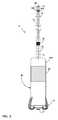
- FIG. 1is a conceptual diagram illustrating an example cardiac pacing system that comprises an implantable medical device (IMD) and an extension.
- IMDimplantable medical device
- FIG. 2is a conceptual illustration of another example cardiac pacing system that includes an IMD and an extension.
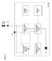
- FIG. 3is a functional block diagram of an example IMD.
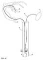
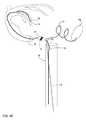
- FIGS. 4A-4Fillustrate various steps of an example method for implanting the system depicted in FIG. 1 .
- FIG. 5is a flow chart illustrating an example method for implanting a cardiac pacing system in a heart of a patient.
- FIG. 6is a conceptual illustration of a distal housing of an example extension.
- FIG. 7is a conceptual illustration of a cutaway of an distal housing of an example extension.
- FIG. 8is a conceptual illustration of an example guidewire and an example stiffener.
- This disclosureis directed to a system and method for implanting a cardiac pacing system capable of providing biventricular pacing to a patient.
- the systemcomprises an IMD which is configured to be implanted in a chamber of the heart, and an extension or lead including one or more electrodes, also configured for placement within the heart, e.g., in a different chamber than the IMD.
- the system and methodare configured to modify a leadless pacing device (LPD) in a manner so that it may provide biventricular pacing.
- LPDleadless pacing device
- an extension that includes one or more electrodesmay be mechanically connected to a housing of the LPD such that it extends from the housing, and the one or more electrodes may be electrically connected to a sensing module of the LPD, a stimulation module of the LPD, or both the sensing and stimulation modules.
- the extensionincludes two electrodes, although any suitable number of electrodes may be used in other examples.
- a proximate electrode(closer to the LPD) may be positioned approximately 3-10 centimeters (cm) from the distal end of the LPD and a distal electrode may be positioned approximately 20-25 cm from the distal end of the LPD.
- the electrodes of the extensionmay be used for sensing electrical cardiac signals, delivering electrical stimulation, or both.
- the LPDmay be programmed to sense atrial signals via the proximate electrode and to provide pacing stimulation pulses via the distal electrode.
- At least one electrode (e.g., the distal electrode) of the extensionmay be positioned on a housing that is attached to the extension.
- the IMDis implanted in the right ventricle.
- One or more electrodes on the IMDmay provide electrical stimulation to the right ventricle, as well as sense electrical signals from the ventricle.
- the distal electrode of the extensionmay be implanted in a contrary vein via the coronary sinus. In some examples, the coronary sinus is accessed from the inferior vena cava.
- the housing of the extensionmay include one or more features that aid the implantation of the housing in a chamber of a heart of the patient, e.g., aid in the control of the housing position relative to the chamber.
- the housingmay define a hole that includes a central axis that is parallel to the longitudinal axis of the extension.
- a tethermay be installed through the hole. The tether may be position such that a first portion of the tether is one side of the housing and a second portion of the tether is on the other side of the housing.
- the tethermay help control the position of the housing, and, therefore, aid in proper positioning of the extension relative to a target stimulation site (e.g., a left ventricle).
- a clinician implanting the system in a patientmay pull on the tether to help move the housing of the extension in a first direction, e.g., towards the clinician, and may also use a pusher to move the housing in a second direction opposite the first direction.
- the pushermay include an eyelet or another feature at a distal end that is configured to engage with the housing to apply a force against the housing to move the housing in the second direction.
- a guidewiremay further aid in the implantation of the distal electrode of the extension in a patient.
- a guidewireincluding a first guidewire portion, e.g., which may be defined by a standard guidewire, and a second guidewire portion.
- the second guidewire portionmay be or may comprise, for example, a suture thread or another material that is more flexible than the first guidewire portion.
- a proximal end of the second guidewire portionmay be attached to a proximal end of the first tether portion.
- a stiffening tubemay be used to stiffen the second guidewire portion while the guidewire is being placed.
- the stiffening tubecan be, for example, formed from a biocompatible plastic or another material that is more stiff than the second guidewire portion.
- a clinicianmay be guide the guidewire to the target chamber of the heart of the patient using a catheter that defines a pathway for the guidewire, and, after the distal end of the first guidewire portion is placed at the desired location within the patient, the stiffening tube may be removed from the patient along with the catheter.
- a clinicianmay introduce a pusher into the patient, e.g., by threading a distal end of the pusher on the second tether portion and then pushing the pusher along the second tether portion to a position proximate the housing of the extension.
- the pusheris relatively stiff and is configured to apply a force against the housing of the extension to help change the position of the housing within the patient.
- the pushermay be made of wire and may include an eyelet at the end, the eyelet being configured to receive the tether and the guidewire.
- the eyeletmay be closed, such that only the end of the tether may be threaded through the eyelet. This may be referred to as a threading in a longitudinal direction.
- the eyeletmay be open, such that the tether may be threaded through the eyelet in either the longitudinal direction or a lateral direction, in which a section of the tether between the proximal and distal ends may be introduced into the eyelet through the opening.
- the pushermay be used to push the electrode through an introducer to the target position within a heart of the patient, e.g., into the right atrium or another chamber.
- the proximal end of the threadmay be attached to the first tether portion.
- a clinicianmay pull on the second tether portion, e.g., in a direction towards the clinician to remove the tether from the hole. Because the second guidewire portion is mechanically connected to the first tether portion, once the tether has been removed, the guidewire replaces the tether within the hole in the housing. The clinician may then use pusher to push the housing along the guidewire to the target location within the patient.
- the clinicianmay push on the pusher to move the electrode distally (in a direction away from the clinician) or pull on both the guidewire and the pusher to move the electrode in the proximal direction (in a direction towards the clinician).
- a cardiac pacing system consistent with the present disclosuremay be contained with the patient's heart once implanted. By locating the IMD and the extension in the heart, the risk of lead fracture along the path from the IMD implant location to the heart is eliminated.
- FIG. 1is a conceptual diagram illustrating an example cardiac pacing system 10 that comprises an implantable medical device (IMD) 12 and an extension 14 implanted in patient 22 .
- IMD 12is a leadless pacing device because IMD 12 is not connected to any leads that extend outside of heart 18 .
- Extension 14is configured to position a first electrode (not shown) proximate to or within a chamber of heart 18 other than the one in which IMD 12 implanted.
- IMD 12is implanted in right ventricle 16 of heart 18 of patient 22 . More particularly, IMD 12 is fixed or attached to the inner wall of the right ventricle 16 proximate to the apex of the right ventricle in the example of FIG.
- IMD 12may be fixed to the inner wall of right ventricle 16 at another location, e.g., on the intraventricular septum or free-wall of the right ventricle, or may be fixed to the outside of heart 18 , i.e., epicardially, proximate to right ventricle 16 . In other examples, IMD may be fixed within, on, or near the left-ventricle of heart 18 .
- extension 14is configured to extend away from IMD 12 and into coronary sinus 26 when IMD 12 is implanted in an apex of right ventricle 16 .
- extension 14may have a length that permits extension 14 to reach a target vein within the coronary sinus 26 in order for at least one electrode of extension 14 to provide electrical stimulation to the left ventricle of heart 18 .
- extension 14may have a length of approximately 25 centimeters (cm) (as measured from the proximal end connected to IMD to a distal most electrode of extension 14 ).
- extension 14may have a relatively small cross-sectional dimension (where the cross-section is taken in a direction perpendicular to a longitudinal axis of extension 14 ) and flexible enough to permit the tricuspid valve to sufficiently close around extension 14 to prevent backflow into right atrium 24 from right ventricle 16 .
- extension 14may be about 4 French (i.e., about 1.33 millimeters (mm)) in diameter.
- extension 14may include a first portion approximately 4 French in diameter and a second, more distal, portion about 2 French (i.e., about 0.66 mm) in diameter.
- IMD 12is configured to electrical activity of right atrium 24 , right ventricle 16 and/or the left ventricle (via an electrode in the coronary sinus). IMD 12 may also be configured to generate and delivering pacing stimulation to both the right and left ventricles.
- the most distal electrode (not shown) of extension 14is affixed to heart 18 via coronary sinus 26 while a second electrode of extension 14 is not affixed to cardiac tissue. Extension 14 is configured to continue to extend away from IMD 12 towards right atrium 24 , even in the presence of blood flow from right atrium 24 to right ventricle 16 .
- medical device programmer 20which is configured to program IMD 12 and retrieve data from IMD 12 .
- Programmer 20may be a handheld computing device, desktop computing device, a networked computing device, etc.
- Programmer 20may include a computer-readable storage medium having instructions that cause a processor of programmer 20 to provide the functions attributed to programmer 20 in the present disclosure.
- IMD 12may wirelessly communicate with programmer 20 .
- IMD 12may transfer data to programmer 20 and may receive data from programmer 20 .
- Programmer 20may also wirelessly program and/or wirelessly charge IMD 12 .
- Data retrieved from IMD 12 using programmer 20may include cardiac EGMs stored by IMD 12 that indicate electrical activity of heart 18 and marker channel data that indicates the occurrence and timing of sensing, diagnosis, and therapy events associated with IMD 12 .
- Data transferred to IMD 12 using programmer 20may include, for example, operational programs for IMD 12 that causes IMD 12 to operate as described herein.
- Pacing system 10may be implanted in right ventricle 16 or another chamber of heart 18 , using any suitable technique. In some cases, pacing system 10 may be implanted according to the method discussed below with respect to FIGS. 4A-4F and 5 .
- extension 14includes a feature configured to facilitate control of the extension during implantation of the extension in the heart.
- extension 14may include a housing that defines a hole or extension 14 may otherwise define an opening through which a tether may be thread.
- extension 14may include an eyelet proximate a distal most electrode of extension 14 . A tether may be fed through the hole or eyelet during implantation of IMD 12 and extension 14 in heart 18 .
- the tethermay provide a physical connection to extension 14 that may be used to control the positioning of a distal portion of extension 14 .
- the tethermay be used to position a pusher and a guidewire proximate the distal portion of the guidewire; the pusher and guidewire may then be used to control the position of the distal most portion of extension 14 relative to heart 18 .
- the guidewire, the tether and the pusherare removed from patient 22 .
- FIG. 2is a conceptual illustration of an example pacing system 10 that includes IMD 12 and extension 14 .
- IMD 12is configured to be implanted within a chamber of a heart of a patient, e.g., to monitor electrical activity of the heart and/or provide electrical therapy to the heart.
- IMD 12includes outer housing 30 , a plurality of fixation tines 32 and electrodes 33 and 34 .
- Extension 14includes electrodes 36 and 38 A, 38 B, housing 40 and fixation elements 42 .
- Outer housing 30has a size and form factor that allows IMD 12 to be entirely implanted within a chamber of a heart of a patient.
- outer housing 16may have a cylindrical (e.g., pill-shaped) form factor.
- IMD 12may include a fixation mechanism configured to fix IMD 12 to cardiac tissue.
- IMD 12includes fixation tines 32 extending from housing 30 and configured to engage with cardiac tissue to substantially fix a position of housing 30 within the chamber of the heart 18 .
- Fixation tines 32are configured to anchor housing 30 to the cardiac tissue such that IMD 12 moves along with the cardiac tissue during cardiac contractions.
- Fixation tines 32may be fabricated from any suitable material, such as a shape memory material (e.g., Nitinol). Although IMD 12 includes a plurality of fixation tines 32 that are configured to anchor IMD 12 to cardiac tissue in a chamber of a heart, in other examples, IMD 12 may be fixed to cardiac tissue using other types of fixation mechanisms, such as, but not limited to, barbs, coils, and the like.
- a shape memory materiale.g., Nitinol
- Housing 30houses electronic components of IMD 12 , e.g., a sensing module for sensing cardiac electrical activity via one ore more combinations of electrodes 33 , 34 , 36 38 A, and 38 B and an electrical stimulation module for delivering electrical stimulation therapy via one or more combinations of electrodes 33 , 34 , 36 , 38 A, and 38 B.
- Electronic componentsmay include any discrete and/or integrated electronic circuit components that implement analog and/or digital circuits capable of producing the functions attributed to IMD 12 described herein.
- housing 30may also house components for sensing other physiological parameters, such as acceleration, pressure, sound, and/or impedance. Although shown with both electrodes 33 and 34 , in some examples, housing 30 may only include one or the other of electrodes 33 and 34 .
- housing 30may also house a memory that includes instructions that, when executed by one or more processors housed within housing 30 , cause IMD 12 to perform various functions attributed to IMD 12 herein.
- housing 30may house a communication module that enables IMD 12 to communicate with other electronic devices, such as a medical device programmer.
- housing 30may house an antenna for wireless communication.
- Housing 30may also house a power source, such as a battery. Housing 30 can be hermetically or near-hermetically sealed in order to help prevent fluid ingress into housing 30 .
- IMD 12is configured to sense electrical activity of the heart and deliver electrical stimulation to the heart via one or more combinations of electrodes 33 , 34 , 36 , 38 A, and 38 B. In some examples, sensing of electrical activity occurs via a first combination of electrodes and delivery of electrical stimulation occurs via a second, different, combination of electrodes. IMD 12 comprises electrodes 33 and 34 and extension 14 comprises electrodes 36 , 38 A, and 38 B. Although shown with three electrodes 36 , 38 A, and 38 B in FIG. 2 , in some examples, extension 14 may only include distal electrode 38 A, or may include only electrodes 38 A, 38 B on housing 40 .
- Electrodes 33 and 34may be mechanically connected to housing 30 .
- electrodes 33 and 34may be defined by an outer portion of housing 30 that is electrically conductive.
- electrode 34may be defined by conductive portion 30 A of housing 30 .
- Conductive portion 30 Amay, in some examples, define at least part of a power source case that houses a power source (e.g., a battery) of IMD 12 .
- the power source casemay house a power source (e.g., a battery) of IMD 12 .
- Electrodes 33 and 34are electrically isolated from each other.
- Electrode 33may be referred to as a tip electrode, and fixation tines 32 may be configured to anchor IMD 12 to cardiac tissue such that electrode 33 maintains contact with the cardiac tissue.
- a portion of housing 30may be covered by, or formed from, an insulative material to isolate electrodes 33 and 34 from each other and/or to provide a desired size and shape for one or both of electrodes 33 and 34 .
- Extension 14is configured to position electrodes 36 , 38 A, 38 B, or just electrodes 38 A, 38 B within a chamber other than the one in which IMD 12 is implanted. In this way, extension 14 may extend the sensing and pacing capabilities of system 10 .
- electrode 36is electrically connected to at least some electronics of IMD 12 (e.g., a sensing module and a stimulation module) via an electrical conductor of extension 14 and an electrically conductive portion 30 A of housing 30 of IMD 12 , the electrically conductive portion 30 A being electrically isolated from electrode 33 , but electrically connected to electrode 34 .
- electrodes 34 , electrode 36may have the same polarity and are electrically common.
- Conductive portion 30 A of housing 16may be electrically connected to at least some electronics of LPD 12 (e.g., a sensing module, an electrical stimulation module, or both), such that conductive portion 30 A defines part of an electrically conductive pathway from electrode 36 to the electronics.
- electronics of LPD 12e.g., a sensing module, an electrical stimulation module, or both
- Electrodes 38 A, 38 Bare also electrically connected to at least some electronics of IMD 12 (e.g., a sensing module and a stimulation module) via one or more electrical conductors of extension 14 .
- electrodes 38 A, 38 Bare electrically connected to at least some electronics of IMD 12 via different electrodes.
- one or both of electrodes 38 A, 38 Bmay be electrically common with electrode 34 and/or electrode 36 .
- Extension 14includes a first extension portion 35 and a second extension portion 37 .
- electrode 36is carried by a first extension portion 35 of extension 14 , and is located at a distal portion of first extension portion 35 , the distal being further from IMD 12 than a proximal portion.
- first extension portion 35may be a self-supporting body and is between approximately 5 cm and 12 cm in length. In other examples, however, electrode 36 may have another position relative to first extension portion 35 , such mid-way between housing 30 and the distal end of first extension portion 35 , or otherwise away from the distal end of first extension portion 35 .
- a center of electrode 36may be between approximately 3 cm and 10 cm from the distal end of IMD 12 (i.e., the end closest to extension 14 ). In some examples, a center of electrode 36 may be approximately 10 cm from the distal end of IMD 12 .
- IMD 12senses electrical activity of right atrium 24 of heart 18 of patient 22 via electrode 36 ; extension 14 may be configured such that when IMD 12 is implanted in right ventricle 16 , electrode 36 is located within right atrium 24 .
- Electrode 36may have any suitable configuration.
- electrode 36may have a ring-shaped configuration, or a partial-ring configuration.
- Electrode 36may be formed from any suitable material, such as a titanium nitride coated metal.
- Second extension portion 37is distal to first extension portion 35 , such that first extension portion 35 is positioned between IMD 12 and second extension portion 37 .
- second portion 37has a cross-sectional dimension (e.g., a diameter) approximately equal to the diameter of first portion 35 .
- the diameter of second extension portion 37may be approximately 4 French.
- second extension portion 37has a cross-sectional dimension smaller then the cross-sectional dimension of first extension portion 35 .
- the diameter of second extension portion 37may be approximately 2 French.
- first and second extension portions 35 , 37are configured such that when IMD 12 is implanted in right ventricle 16 , electrodes 38 A, 38 B and housing 40 of extension 14 are implanted in a left ventricle of heart 18 .
- the length of second extension portion 37may be approximately 15 cm to 20 cm, and extension 14 may have a total length of approximately 20 cm to 25 cm.
- Electrodes 38 A, 38 Bare located at the distal end of second extension portion 37 on a housing 40 .
- Housing 40may include a hole or eyelet that includes a central axis H A that is parallel to a longitudinal axis E A of extension 14 .
- the hole or eyeletmay be configured to receive tether and/or a guidewire.
- Electrodes 38 A, 38 Bmay have any suitable configuration.
- electrodes 38 A, 38 Bmay each be a ring-shaped configuration, or a partial-ring configuration.
- Electrodes 38 A, 38 Bmay be formed from any suitable material, such as a titanium nitride coated metal.
- housing 40 including two electrodes 38 A, 38 Bare shown in FIG. 2 , in other examples of system 10 , housing 40 may include any suitable number of electrodes, such as one or more than two electrodes.
- Second portion 37 of extension 14may also include one or more fixation elements 42 configured to engage with tissue to substantially fix a position of electrodes 38 A, 38 B relative to heart 18 of patient 22 .
- Fixation elements 42may be any suitable type of fixation element, such as tines, double-bended elements, s-curve element, barbs, coils, or the like.
- the relative spacing between electrodes 36 , 38 A, 38 Bmay vary based on the type of stimulation and/or sensing system 10 is configured to provide.
- electrode 36is spaced from electrodes 38 A, 38 B along extension 14 such that when implanted system 10 is implanted in heart 22 , electrode 36 is located within the right atrium, and electrodes 38 A, 38 B are located within the coronary sinus proximate to the left ventricle.
- system 10may be used to sense electrical activity in both right ventricle 16 and the left ventricle, as well as deliver electrical stimulation to both right ventricle 16 and left ventricle, e.g., to provide biventricular pacing therapy.
- FIG. 3is a functional block diagram of an example IMD 12 .
- IMD 12includes a processing module 50 , memory 52 , stimulation module 54 , electrical sensing module 56 , communication module 58 , sensor 60 , and power source 62 .
- Power source 62may include a battery, e.g., a rechargeable or non-rechargeable battery.
- Modules included in IMD 12represent functionality that may be included in IMD 12 of the present disclosure.
- Modules of the present disclosuremay include any discrete and/or integrated electronic circuit components that implement analog and/or digital circuits capable of producing the functions attributed to the modules herein.
- the modulesmay include analog circuits, e.g., amplification circuits, filtering circuits, and/or other signal conditioning circuits.
- the modulesmay also include digital circuits, e.g., combinational or sequential logic circuits, memory devices, and the like.
- the functions attributed to the modules hereinmay be embodied as one or more processors, hardware, firmware, software, or any combination thereof.
- modulesDepiction of different features as modules is intended to highlight different functional aspects, and does not necessarily imply that such modules must be realized by separate hardware or software components. Rather, functionality associated with one or more modules may be performed by separate hardware or software components, or integrated within common or separate hardware or software components.
- Processing module 50may include any one or more of a microprocessor, a controller, a digital signal processor (DSP), an application specific integrated circuit (ASIC), a field-programmable gate array (FPGA), or equivalent discrete or integrated logic circuitry.
- processor 50may include multiple components, such as any combination of one or more microprocessors, one or more controllers, one or more DSPs, one or more ASICs, or one or more FPGAs, as well as other discrete or integrated logic circuitry.
- Processing module 50may communicate with memory 52 .
- Memory 52may include computer-readable instructions that, when executed by processing module 50 , cause processing module 50 to perform the various functions attributed to processing module 50 herein.
- Memory 52may include any volatile, non-volatile, magnetic, or electrical media, such as a random access memory (RAM), read-only memory (ROM), non-volatile RAM (NVRAM), electrically-erasable programmable ROM (EEPROM), Flash memory, or any other memory device.
- RAMrandom access memory
- ROMread-only memory
- NVRAMnon-volatile RAM
- EEPROMelectrically-erasable programmable ROM
- Flash memoryor any other memory device.
- memory 52may include instructions that, when executed by one or more processors, cause the modules to perform various functions attributed to the modules herein.
- memory 52may include pacing instructions and values. The pacing instructions and values may be updated by programmer 20 ( FIG. 1 ).
- Stimulation module 54 and electrical sensing module 56are electrically coupled to electrodes 33 , 34 , 36 , 38 A, 38 B.
- Processing module 50is configured to control stimulation module 54 to generate and deliver electrical stimulation to heart 18 (e.g., right ventricle 16 and the left ventricle via coronary sinus 26 in the example shown in FIG. 1 ) via a selected subset of electrodes 33 , 34 , 36 , 38 A, 38 B.
- stimulation module 54may deliver pacing electrical stimulation to right ventricle 16 via electrodes 33 and 34 , which are configured to be implanted within right ventricle 16 .
- stimulation module 54may deliver pacing electrical stimulation to the left ventricle via electrodes 38 A, 38 B, which are configured to be implanted within the left ventricle.
- Electrical stimulationmay include, for example, pacing pulses, or any other suitable electrical stimulation.
- Processing module 50may control stimulation module 54 to deliver electrical stimulation therapy via a selected subset of electrodes 33 , 34 , 36 , 38 A, 38 B according to one or more therapy programs including pacing instructions that define a ventricular pacing rate, which may be stored in memory 52 .
- processing module 50is configured to control electrical sensing module 56 monitor signals from any suitable subset of electrodes 33 , 34 , 36 , 38 A, 38 B in order to monitor electrical activity of heart 18 .
- electrical sensing module 56may sense electrical activity within right ventricle 16 via electrodes 33 , 34 , may sense electrical activity within right atrium 24 via electrodes 33 , 36 , may sense electrical activity within the right ventricle via electrodes 38 A, 38 B, or any combination of the aforementioned sensing may be performed by sensing module 56 .
- Electrical sensing module 56may include circuits that acquire electrical signals. Electrical sensing module 56 may acquire electrical signals form a subset of electrodes 33 , 34 , 36 and 38 A, 38 B. Electrical signals acquired by electrical sensing module 56 may include intrinsic cardiac electrical activity, such as intrinsic atrial depolarization and/or intrinsic ventricular depolarization. Electrical sensing module 56 may filter, amplify, and digitize the acquired electrical signals to generate raw digital data. Processing module 50 may receive the digitized data generated by electrical sensing module 56 . In some examples, processing module 50 may perform various digital signal processing operations on the raw data, such as digital filtering.
- Processing module 50may sense cardiac events based on the data received from electrical sensing module 56 .
- processing module 50may sense atrial electrical activity based on the data received from electrical sensing module 56 .
- processing module 50may detect P-waves indicative of atrial activation events based on the data received from electrical sensing module 56 via electrodes 33 , 36 .
- processing module 50may also sense ventricular electrical activity based on the data received from electrical sensing module 56 .
- processing module 50may detect R-waves indicative of right ventricular activation events based on the data received from electrical sensing module 56 via electrodes 33 , 34 .
- processor 50may detect the R-waves and P-waves from the same sensed signal.
- the sensing vectorcan be between electrodes 33 and 36 , for example.
- processing module 50may detect a signal characteristic indicative of left ventricular activation events based on the data received from electrical sensing module 56 via electrodes 38 A, 38 B, or via electrodes 36 , 38 A, or via electrodes 36 , 38 B.
- IMD 12in addition to electrical sensing module 56 , IMD 12 includes sensor 60 , which may comprise at least one of a variety of different sensors.
- sensor 60may comprise at least one of a pressure sensor and an accelerometer.
- Sensor 60may generate signals that indicate at least one of parameter of patient 22 , such as, but not limited to, at least one of: an activity level of patient 22 , a hemodynamic pressure, and heart sounds.
- Communication module 58may include any suitable hardware (e.g., an antenna), firmware, software, or any combination thereof for communicating with another device, such as programmer 20 ( FIG. 1 ) or a patient monitor. Under the control of processing module 50 , communication module 58 may receive downlink telemetry from and send uplink telemetry to other devices, such as programmer 2 or a patient monitor, with the aid of an antenna included in communication module 58 .
- suitable hardwaree.g., an antenna
- firmwaree.g., software
- Communication module 58may receive downlink telemetry from and send uplink telemetry to other devices, such as programmer 2 or a patient monitor, with the aid of an antenna included in communication module 58 .
- FIGS. 4A-4Fillustrate a method of implanting system 10 , and, in particular, housing 40 of extension 14 in a desired location within heart 18 , e.g., to position one or both electrodes 38 A, 38 B to sense electrical activity of a particular chamber (e.g., the left ventricle) or deliver electrical stimulation to the particular chamber.
- IMD 12has been implanted in the right ventricle 16 ( FIG. 1 ), and extension 14 enters right atrium 24 ( FIG. 1 ) via tricuspid valve 64 .
- a tether 69comprising a first tether portion 66 and a second tether portion 68 is threaded through a hole in housing 40 , the hole having a central axis that is substantially parallel (e.g., parallel or nearly parallel) to the longitudinal axis of extension 14 .
- first tether portion 66is positioned on one side of housing 40 and extends from one end of the hole
- the second tether portion 68is on the other side of housing 40 and extends form the other end of the hole.
- first tether portion 66is a different color than second tether portion 68 in order to help the clinician visually distinguish between the tether portions 66 , 68 .
- Tether 69may be placed within the hole in housing 40 prior to implantation. For example, a manufacturer of extension 14 may install tether 69 in the hole of housing 40 .
- housing 40 and tether 69may be introduced into heart 18 via introducer 70 .
- Introducer 70may be introduced to heart 18 via the femoral vein (not shown). In the example shown in FIG. 4A , housing 40 and tether 69 are located within introducer 70 .
- Introducer 70is sized to receive extension 14 and tether 69 , but is still relatively small in order to reduce the invasiveness of introducer 70 .
- introducer 70may have a diameter of approximately 22 French, although other dimensions are contemplated. The diameter of introducer 70 may be the diameter of a cross-section of introducer 70 taken along an axis perpendicular to a longitudinal axis of introducer 70 .
- Guidewire 72 and catheter 74may be used to define a pathway for extension 14 from introducer 70 to a location within coronary sinus 26 or another location within heart 18 .
- guidewire 72is introduced into a target vein 76 using a catheter 74 , which may be guided to a location proximate coronary sinus 26 via introducer 70 .
- target vein 76branches from the coronary sinus 26 .
- the target veinis the coronary vein of the left ventricle.
- Guidewire 72 and catheter 74may have any suitable configuration.
- guidewire 72has a proximal guidewire portion and a distal guidewire portion having a different configuration than the proximal guidewire portion.
- the distal guidewire portionmay be the portion of guidewire 72 that is furthest from the clinician when guidewire 72 is being inserted through tissue.
- the distal guidewire portione.g., the distal most 20 cm
- guidewire 72may be configured as a standard guidewire formed from any suitable wire (e.g., a nickel titanium wire).
- the distal guidewire portionmay be formed from a wire that tapers in a distal direction from a diameter of about 0.014 inches to a diameter of about 0.012 inches, and becomes more flexible as it tapers.
- Other guidewire configurations and other guidewire dimensionsmay also be used, and may vary based on the implant location of housing 40 of extension 14 .
- the proximal guidewire portion of guidewire 72may be a suture thread, e.g., a 0.010 cm diameter suture thread, rather than a wire.
- the proximal guidewire portionmay be is temporarily stiffened with a stiffening tube within which the proximal guide portion may be introduced.
- Catheter 74may be configured to receive the stiffening tube.
- the stiffening tubeis formed from a biocompatible plastic material and has a 0.012 cm inner diameter, and a 0.030 outer diameter.
- first tether portion 66is attached to the proximal end of the guidewire 72 (e.g., attached to the proximal guidewire's thread-like portion) at attachment point 80 .
- the proximal, threadlike, portion of guidewire 72portion 75 shown in FIG. 8 , below
- a drop of instant adhesivemay be applied in order to insure the integrity of the attachment.
- a clinicianmay introduce pusher 78 into introducer 70 .
- pusher 78is made of wire.
- Pusher 78may include eyelet 79 or another feature at a distal end 78 A that is sized to receive tether 68 , and engage with housing 40 to apply a force against housing 40 to move housing 40 in a direction away from introducer 70 .
- pusher 78is made of stainless steel wire.
- pusher 78may be approximately 0.020 inches in diameter.
- eyelet 79is defined by one or more turns of the wire from which pusher 78 is formed. As shown in FIG.
- second tether portion 68is threaded through eyelet 79 of pusher 78 , thereby securing the relative lateral position between pusher 78 and tether 69 .
- Pusher 78may be moved along tether 69 (i.e., in a direction along a longitudinal axis of tether 69 ) to reach housing 40 .
- a clinicianmay pull on second tether portion 68 , in a direction away from housing 40 (and, in some examples, in a direction away from patient 22 ).
- the clinicianmay hold housing 40 in place with pusher 78 as second tether portion 68 is pulled.
- tether 69Prior to pulling on tether 69 , tether 69 was extending through the hole defined by housing 40 .
- first tether portion 66is pulled through the hole define by housing 40 , such that the proximal guidewire portion of guidewire 72 , which is attached to first tether portion 66 , is fed through the hole defined by housing 69 .
- guidewire 72may replace tether 69 , as shown in FIG.
- the proximal guidewire portionmay be pulled through the hole defined by housing 69 because it is formed from a relatively flexible material, e.g., a suture thread, and not from the stiffer wire material with which first guidewire portion is formed from.
- Guidewire 72may be used to guide housing 40 to target vein 76 .
- tether 69provides a relatively quick and simple way to thread guidewire 72 through the hole in housing 40 while housing 40 is implanted in patient 22 .
- pusher 78is used to push housing 40 along guidewire 72 towards target vein 76 (or other desired location).
- target vein 76may be selected in order to provide biventricular pacing.
- fine adjustment of the location of electrodes 38 A, 38 B relative to specific locations of heart 18may be achieved by pushing on pusher 78 to move electrodes 38 A, 38 B distally (away from introducer 70 ), and by pulling on guidewire 72 and pusher 89 to move electrodes 38 A, 38 B in a proximal direction, towards introducer 70 .
- FIG. 4Fdepicts an example implantation setup of system 10 .
- FIG. 5is a flowchart illustrating an example method for implanting cardiac pacing system 10 in a heart 18 of patient 22 to provide biventricular pacing.
- a clinicianintroduces an IMD 12 to the right ventricle 16 of patient 22 ( 82 ).
- IMD 12may be introduced into the heart 18 via a femoral vein.
- pacing system 10includes a tether, such as tether 69 , which is threaded through a hole in housing 40 of extension 14 .
- the cliniciandirects a guidewire 72 to a target vein ( 84 ).
- the target veinmay be off of the coronary sinus, and located so that when in place, electrodes 38 A, 38 B on housing 40 of extension 14 may provide pacing stimulation to the left ventricle.
- a proximal end of the guidewire 72may be attached to the first tether portion 66 of tether 69 .
- the clinicianintroduces a pusher 78 along the second tether portion 68 of the tether to housing 40 ( 86 ).
- the clinicianmay the remove tether 69 from housing 40 by pulling the second tether portion 68 ( 88 ). Pulling on the second portion 68 of the tether results in guidewire 72 replacing tether 69 within the hole in housing 40 .
- the clinicianmay then push housing 40 towards the target vein along the guidewire 72 using the pusher 78 ( 90 ).
- Pusher 78 and guidewire 72are used to position electrodes 38 A, 38 B on housing 40 at a desired location, which may be selected in order provide adequate pacing stimulation to the left ventricle of heart 18 .
- FIG. 6is a conceptual illustration of a distal housing 40 .
- Distal housing 40includes electrodes 38 A and 38 B and hole 41 .
- Hole 41is configured to accept tether 69 and/or guidewire 72 .
- the longitudinal axis of hole 41is parallel to the longitudinal axis E A of extension 14 .
- FIG. 7is a conceptual illustration of a cutaway of a distal housing 40 at the distal end of second extension portion 37 .
- the cutaway of housing 40shows hole 41 .
- the longitudinal axis of hole 41is parallel to the longitudinal axis of the second extension portion 37 .
- FIG. 8is a conceptual illustration of guidewire 72 and stiffening tube 77 .
- Guidewire 72includes first guidewire portion 73 and a second guidewire portion 75 .
- the first guidewire portion 73resembles a standard guidewire and can be formed from a standard guidewire in some examples.
- the first guidewire portion 73is approximately 20 cm in length.
- the first guidewire portionmay taper from 0.014 inches to 0.012 inches and becomes more flexible as it tapers.
- the second guidewire portion 75may be a thread.
- the threadmay be approximately 0.010 inches in diameter.
- the second guidewire portion 75may be encompassed by stiffening tube 77 .
- Stiffening tubemay be made of plastic.
- stiffening tube 77may have a 0.012 inch inside diameter, and a 0.030 inch outside diameter.
- processorsincluding one or more microprocessors, DSPs, ASICs, FPGAs, or any other equivalent integrated or discrete logic circuitry, as well as any combinations of such components, embodied in programmers, such as physician or patient programmers, stimulators, image processing devices or other devices.
- processorsincluding one or more microprocessors, DSPs, ASICs, FPGAs, or any other equivalent integrated or discrete logic circuitry, as well as any combinations of such components, embodied in programmers, such as physician or patient programmers, stimulators, image processing devices or other devices.
- processoror “processing circuitry” may generally refer to any of the foregoing logic circuitry, alone or in combination with other logic circuitry, or any other equivalent circuitry.
- Such hardware, software, firmwaremay be implemented within the same device or within separate devices to support the various operations and functions described in this disclosure.
- any of the described units, modules or componentsmay be implemented together or separately as discrete but interoperable logic devices. Depiction of different features as modules or units is intended to highlight different functional aspects and does not necessarily imply that such modules or units must be realized by separate hardware or software components. Rather, functionality associated with one or more modules or units may be performed by separate hardware or software components, or integrated within common or separate hardware or software components.
- the functionality ascribed to the systems, devices and techniques described in this disclosuremay be embodied as instructions on a computer-readable medium such as RAM, ROM, NVRAM, EEPROM, FLASH memory, magnetic data storage media, optical data storage media, or the like.
- the instructionsmay be executed to support one or more aspects of the functionality described in this disclosure.
Landscapes
- Health & Medical Sciences (AREA)
- Life Sciences & Earth Sciences (AREA)
- Heart & Thoracic Surgery (AREA)
- Animal Behavior & Ethology (AREA)
- Veterinary Medicine (AREA)
- Public Health (AREA)
- Engineering & Computer Science (AREA)
- Biomedical Technology (AREA)
- General Health & Medical Sciences (AREA)
- Cardiology (AREA)
- Nuclear Medicine, Radiotherapy & Molecular Imaging (AREA)
- Radiology & Medical Imaging (AREA)
- Biophysics (AREA)
- Pulmonology (AREA)
- Anesthesiology (AREA)
- Hematology (AREA)
- Vascular Medicine (AREA)
- Physiology (AREA)
- Electrotherapy Devices (AREA)
Abstract
Description
The disclosure relates to cardiac pacing, and more particularly, to cardiac pacing using a pacing device implanted within the heart.
An implantable pacemaker may deliver pacing pulses to a patient's heart and monitor conditions of the patient's heart. In some examples, the implantable pacemaker comprises a pulse generator and one or more electrical leads. The pulse generator may, for example, be implanted in a small pocket in the patient's chest. The electrical leads may be coupled to the pulse generator, which may contain circuitry that generates pacing pulses and/or senses cardiac electrical activity. The electrical leads may extend from the pulse generator to a target site (e.g., an atrium and/or a ventricle) such that electrodes at the distal ends of the electrical leads are positioned at a target site. The pulse generator may provide electrical stimulation to the target site and/or monitor cardiac electrical activity at the target site via the electrodes.
A leadless pacing device has also been proposed for sensing electrical activity and/or delivering therapeutic electrical signals to the heart. The leadless pacing device may include one or more electrodes on its outer housing to deliver therapeutic electrical signals and/or sense intrinsic depolarizations of the heart. The leadless pacing device may be positioned within or outside of the heart and, in some examples, may be anchored to a wall of the heart via a fixation mechanism.
The disclosure describes devices, systems, and methods for implanting a cardiac pacing system that includes an implantable medical device (hereinafter, “IMD”) configured for implantation within a chamber of a heart of a patient, and an extension extending from a housing of the IMD, which is also configured to be implanted within the heart. The extension includes one or more electrodes with which the IMD may sense electrical cardiac activity and/or provide electrical stimulation. The extension is electrically coupled to a sensing module and/or a stimulation module of the IMD. In some examples, the IMD is configured to be implanted in a first chamber of a heart of a patient (e.g., the right ventricle), and a portion of the extension may be configured to position at least one electrode within or proximate to another chamber of the heart (e.g., the left ventricle), thereby allowing the IMD to deliver biventricular pacing in a patient or to sense electrical activity in at least two chambers of the heart.
In some example, the extension includes a housing that includes one or more electrodes configured to be positioned at a target site within the heart that is within or proximate to a chamber of the heart other than the one in which the IMD is implanted. The housing may define an opening, through which a tether may be threaded. The tether, in conjunction with a guidewire and a pusher, may be used to guide the housing to the target site. In some examples, a proximal end (or a proximal portion) of the guidewire is mechanically connected to a distal end of the tether, such that as the tether is pulled through the hole defined by the housing in a proximal direction, the guidewire is threaded through the hole. In this way, the housing may be threaded through the guidewire and may be guided to the target site via the guidewire.
In some examples, the tether may also be threaded through an eyelet or other opening defined by a pusher. As the tether is pulled through the hole defined by the housing in a proximal direction and the guidewire is threaded through the hole, the guidewire is also threaded through the eyelet defined by the pusher. The pusher is configured to engage with a proximal side of the housing to apply a force to push the housing in a distal direction, towards the target site.
In one example, the disclosure is directed to a system comprising an implantable medical device configured to be implanted in a chamber of a heart of a patient; an extension attached to the implantable medical device, the extension comprising a housing comprising at least one electrode, the housing defining a hole; and a tether comprising a first tether portion and a second tether portion and configured to be threaded through the hole, wherein when the tether is threaded through the hole, the first tether portion and the second tether portion are on opposite sides of the hole.
In another example, the disclosure is directed to a method comprising introducing an implantable medical device to a first chamber of a heart of a patient via a femoral vein, wherein the implantable medical device is attached to an extension comprising a housing including at least one electrode, the housing defining a hole, and wherein a tether is threaded through the hole, the tether including a first tether portion and a second tether portion on an opposite side of the hole from the first tether portion; directing a guidewire to a target vein, the guidewire comprising a first guidewire portion and a second guidewire portion, the second guidewire portion comprising a thread attached to the second tether portion; introducing a pusher up the second tether portion to a position proximate to the housing; removing the tether from the patient by at least pulling the second tether portion to replace the tether with the guidewire; pushing the housing along the guidewire using the pusher.
The details of one or more examples of the disclosure are set forth in the accompanying drawings and the description below. Other features, objects, and advantages of the disclosure will be apparent from the description and drawings, and from the claims.
This disclosure is directed to a system and method for implanting a cardiac pacing system capable of providing biventricular pacing to a patient. The system comprises an IMD which is configured to be implanted in a chamber of the heart, and an extension or lead including one or more electrodes, also configured for placement within the heart, e.g., in a different chamber than the IMD. In some examples, the system and method are configured to modify a leadless pacing device (LPD) in a manner so that it may provide biventricular pacing.
For example, an extension that includes one or more electrodes may be mechanically connected to a housing of the LPD such that it extends from the housing, and the one or more electrodes may be electrically connected to a sensing module of the LPD, a stimulation module of the LPD, or both the sensing and stimulation modules. In some examples, the extension includes two electrodes, although any suitable number of electrodes may be used in other examples. For example, a proximate electrode (closer to the LPD) may be positioned approximately 3-10 centimeters (cm) from the distal end of the LPD and a distal electrode may be positioned approximately 20-25 cm from the distal end of the LPD. The electrodes of the extension may be used for sensing electrical cardiac signals, delivering electrical stimulation, or both. In some examples, the LPD may be programmed to sense atrial signals via the proximate electrode and to provide pacing stimulation pulses via the distal electrode.
In some examples, at least one electrode (e.g., the distal electrode) of the extension may be positioned on a housing that is attached to the extension. In some examples the IMD is implanted in the right ventricle. One or more electrodes on the IMD may provide electrical stimulation to the right ventricle, as well as sense electrical signals from the ventricle. In addition, in some examples in which the IMD is implanted in the right ventricle, the distal electrode of the extension may be implanted in a contrary vein via the coronary sinus. In some examples, the coronary sinus is accessed from the inferior vena cava.
The housing of the extension may include one or more features that aid the implantation of the housing in a chamber of a heart of the patient, e.g., aid in the control of the housing position relative to the chamber. For example, the housing may define a hole that includes a central axis that is parallel to the longitudinal axis of the extension. A tether may be installed through the hole. The tether may be position such that a first portion of the tether is one side of the housing and a second portion of the tether is on the other side of the housing.
The tether may help control the position of the housing, and, therefore, aid in proper positioning of the extension relative to a target stimulation site (e.g., a left ventricle). For example, a clinician implanting the system in a patient may pull on the tether to help move the housing of the extension in a first direction, e.g., towards the clinician, and may also use a pusher to move the housing in a second direction opposite the first direction. In some examples, the pusher may include an eyelet or another feature at a distal end that is configured to engage with the housing to apply a force against the housing to move the housing in the second direction.
In some examples, a guidewire may further aid in the implantation of the distal electrode of the extension in a patient. In some examples, a guidewire including a first guidewire portion, e.g., which may be defined by a standard guidewire, and a second guidewire portion. The second guidewire portion may be or may comprise, for example, a suture thread or another material that is more flexible than the first guidewire portion. A proximal end of the second guidewire portion may be attached to a proximal end of the first tether portion.
In examples in which the second guidewire portion comprises a suture thread, a stiffening tube may be used to stiffen the second guidewire portion while the guidewire is being placed. The stiffening tube can be, for example, formed from a biocompatible plastic or another material that is more stiff than the second guidewire portion. A clinician may be guide the guidewire to the target chamber of the heart of the patient using a catheter that defines a pathway for the guidewire, and, after the distal end of the first guidewire portion is placed at the desired location within the patient, the stiffening tube may be removed from the patient along with the catheter.
A clinician may introduce a pusher into the patient, e.g., by threading a distal end of the pusher on the second tether portion and then pushing the pusher along the second tether portion to a position proximate the housing of the extension. The pusher is relatively stiff and is configured to apply a force against the housing of the extension to help change the position of the housing within the patient. In some examples, the pusher may be made of wire and may include an eyelet at the end, the eyelet being configured to receive the tether and the guidewire. In some examples, the eyelet may be closed, such that only the end of the tether may be threaded through the eyelet. This may be referred to as a threading in a longitudinal direction. In other examples, the eyelet may be open, such that the tether may be threaded through the eyelet in either the longitudinal direction or a lateral direction, in which a section of the tether between the proximal and distal ends may be introduced into the eyelet through the opening.
The pusher may be used to push the electrode through an introducer to the target position within a heart of the patient, e.g., into the right atrium or another chamber. At the proximal end of the introducer, the proximal end of the thread may be attached to the first tether portion. A clinician may pull on the second tether portion, e.g., in a direction towards the clinician to remove the tether from the hole. Because the second guidewire portion is mechanically connected to the first tether portion, once the tether has been removed, the guidewire replaces the tether within the hole in the housing. The clinician may then use pusher to push the housing along the guidewire to the target location within the patient.
For fine adjustments to the electrode location once the housing approaches the end of the guidewire, the clinician may push on the pusher to move the electrode distally (in a direction away from the clinician) or pull on both the guidewire and the pusher to move the electrode in the proximal direction (in a direction towards the clinician).
A cardiac pacing system consistent with the present disclosure may be contained with the patient's heart once implanted. By locating the IMD and the extension in the heart, the risk of lead fracture along the path from the IMD implant location to the heart is eliminated.
In the example shown inFIG. 1 ,extension 14 is configured to extend away fromIMD 12 and intocoronary sinus 26 whenIMD 12 is implanted in an apex ofright ventricle 16. In some examples,extension 14 may have a length that permitsextension 14 to reach a target vein within thecoronary sinus 26 in order for at least one electrode ofextension 14 to provide electrical stimulation to the left ventricle ofheart 18. For example,extension 14 may have a length of approximately 25 centimeters (cm) (as measured from the proximal end connected to IMD to a distal most electrode of extension14). In some examples,extension 14 may have a relatively small cross-sectional dimension (where the cross-section is taken in a direction perpendicular to a longitudinal axis of extension14) and flexible enough to permit the tricuspid valve to sufficiently close aroundextension 14 to prevent backflow intoright atrium 24 fromright ventricle 16. For example,extension 14 may be about 4 French (i.e., about 1.33 millimeters (mm)) in diameter. In some examples,extension 14 may include a first portion approximately 4 French in diameter and a second, more distal, portion about 2 French (i.e., about 0.66 mm) in diameter.
In the example shown inFIG. 1 ,IMD 12 is configured to electrical activity ofright atrium 24,right ventricle 16 and/or the left ventricle (via an electrode in the coronary sinus).IMD 12 may also be configured to generate and delivering pacing stimulation to both the right and left ventricles. In some examples, the most distal electrode (not shown) ofextension 14 is affixed toheart 18 viacoronary sinus 26 while a second electrode ofextension 14 is not affixed to cardiac tissue.Extension 14 is configured to continue to extend away fromIMD 12 towardsright atrium 24, even in the presence of blood flow fromright atrium 24 toright ventricle 16.
Also shown inFIG. 1 ismedical device programmer 20, which is configured to programIMD 12 and retrieve data fromIMD 12.Programmer 20 may be a handheld computing device, desktop computing device, a networked computing device, etc.Programmer 20 may include a computer-readable storage medium having instructions that cause a processor ofprogrammer 20 to provide the functions attributed toprogrammer 20 in the present disclosure.IMD 12 may wirelessly communicate withprogrammer 20. For example,IMD 12 may transfer data toprogrammer 20 and may receive data fromprogrammer 20.Programmer 20 may also wirelessly program and/or wirelessly chargeIMD 12.
Data retrieved fromIMD 12 usingprogrammer 20 may include cardiac EGMs stored byIMD 12 that indicate electrical activity ofheart 18 and marker channel data that indicates the occurrence and timing of sensing, diagnosis, and therapy events associated withIMD 12. Data transferred toIMD 12 usingprogrammer 20 may include, for example, operational programs forIMD 12 that causesIMD 12 to operate as described herein.
Pacingsystem 10 may be implanted inright ventricle 16 or another chamber ofheart 18, using any suitable technique. In some cases, pacingsystem 10 may be implanted according to the method discussed below with respect toFIGS. 4A-4F and 5 . As described in further detail below, in some examples,extension 14 includes a feature configured to facilitate control of the extension during implantation of the extension in the heart. For example,extension 14 may include a housing that defines a hole orextension 14 may otherwise define an opening through which a tether may be thread. For example,extension 14 may include an eyelet proximate a distal most electrode ofextension 14. A tether may be fed through the hole or eyelet during implantation ofIMD 12 andextension 14 inheart 18. The tether may provide a physical connection toextension 14 that may be used to control the positioning of a distal portion ofextension 14. For example, the tether may be used to position a pusher and a guidewire proximate the distal portion of the guidewire; the pusher and guidewire may then be used to control the position of the distal most portion ofextension 14 relative toheart 18. After implantation, the guidewire, the tether and the pusher are removed frompatient 22.
Additionally,housing 30 may also house a memory that includes instructions that, when executed by one or more processors housed withinhousing 30,cause IMD 12 to perform various functions attributed toIMD 12 herein. In some examples,housing 30 may house a communication module that enablesIMD 12 to communicate with other electronic devices, such as a medical device programmer. In some examples,housing 30 may house an antenna for wireless communication.Housing 30 may also house a power source, such as a battery.Housing 30 can be hermetically or near-hermetically sealed in order to help prevent fluid ingress intohousing 30.
In some examples,IMD 12 senses electrical activity ofright atrium 24 ofheart 18 ofpatient 22 viaelectrode 36;extension 14 may be configured such that whenIMD 12 is implanted inright ventricle 16,electrode 36 is located withinright atrium 24.Electrode 36 may have any suitable configuration. For example,electrode 36 may have a ring-shaped configuration, or a partial-ring configuration.Electrode 36 may be formed from any suitable material, such as a titanium nitride coated metal.
In some examples, first andsecond extension portions IMD 12 is implanted inright ventricle 16,electrodes housing 40 ofextension 14 are implanted in a left ventricle ofheart 18. For example, the length ofsecond extension portion 37 may be approximately 15 cm to 20 cm, andextension 14 may have a total length of approximately 20 cm to 25 cm.
The relative spacing betweenelectrodes sensing system 10 is configured to provide. In some examples,electrode 36 is spaced fromelectrodes extension 14 such that when implantedsystem 10 is implanted inheart 22,electrode 36 is located within the right atrium, andelectrodes system 10 may be used to sense electrical activity in bothright ventricle 16 and the left ventricle, as well as deliver electrical stimulation to bothright ventricle 16 and left ventricle, e.g., to provide biventricular pacing therapy.
Modules included inIMD 12 represent functionality that may be included inIMD 12 of the present disclosure. Modules of the present disclosure may include any discrete and/or integrated electronic circuit components that implement analog and/or digital circuits capable of producing the functions attributed to the modules herein. For example, the modules may include analog circuits, e.g., amplification circuits, filtering circuits, and/or other signal conditioning circuits. The modules may also include digital circuits, e.g., combinational or sequential logic circuits, memory devices, and the like. The functions attributed to the modules herein may be embodied as one or more processors, hardware, firmware, software, or any combination thereof. Depiction of different features as modules is intended to highlight different functional aspects, and does not necessarily imply that such modules must be realized by separate hardware or software components. Rather, functionality associated with one or more modules may be performed by separate hardware or software components, or integrated within common or separate hardware or software components.
In addition,processing module 50 is configured to controlelectrical sensing module 56 monitor signals from any suitable subset ofelectrodes heart 18. For example,electrical sensing module 56 may sense electrical activity withinright ventricle 16 viaelectrodes right atrium 24 viaelectrodes electrodes module 56.
In some examples, in addition toelectrical sensing module 56,IMD 12 includessensor 60, which may comprise at least one of a variety of different sensors. For example,sensor 60 may comprise at least one of a pressure sensor and an accelerometer.Sensor 60 may generate signals that indicate at least one of parameter ofpatient 22, such as, but not limited to, at least one of: an activity level ofpatient 22, a hemodynamic pressure, and heart sounds.
Communication module58 may include any suitable hardware (e.g., an antenna), firmware, software, or any combination thereof for communicating with another device, such as programmer20 (FIG. 1 ) or a patient monitor. Under the control ofprocessing module 50, communication module58 may receive downlink telemetry from and send uplink telemetry to other devices, such as programmer2 or a patient monitor, with the aid of an antenna included in communication module58.
In some examples, thefirst tether portion 66 is a different color thansecond tether portion 68 in order to help the clinician visually distinguish between thetether portions Tether 69 may be placed within the hole inhousing 40 prior to implantation. For example, a manufacturer ofextension 14 may installtether 69 in the hole ofhousing 40.
In some examples,housing 40 andtether 69 may be introduced intoheart 18 viaintroducer 70.Introducer 70 may be introduced toheart 18 via the femoral vein (not shown). In the example shown inFIG. 4A ,housing 40 andtether 69 are located withinintroducer 70.Introducer 70 is sized to receiveextension 14 andtether 69, but is still relatively small in order to reduce the invasiveness ofintroducer 70. In some examples,introducer 70 may have a diameter of approximately 22 French, although other dimensions are contemplated. The diameter ofintroducer 70 may be the diameter of a cross-section ofintroducer 70 taken along an axis perpendicular to a longitudinal axis ofintroducer 70.
In some examples, the proximal guidewire portion ofguidewire 72 may be a suture thread, e.g., a 0.010 cm diameter suture thread, rather than a wire. To enableguidewire 72 to be pushed, rotated and pulled, the proximal guidewire portion may be is temporarily stiffened with a stiffening tube within which the proximal guide portion may be introduced.Catheter 74 may be configured to receive the stiffening tube. In some examples, the stiffening tube is formed from a biocompatible plastic material and has a 0.012 cm inner diameter, and a 0.030 outer diameter.
After the distal end ofguidewire 72 is attarget vein 76, as shown inFIG. 4C , both the stiffening tube (if used) andcatheter 74 may be removed frompatient 22, leavingguidewire 72 in place. In the step shown inFIG. 4D ,first tether portion 66 is attached to the proximal end of the guidewire72 (e.g., attached to the proximal guidewire's thread-like portion) atattachment point 80. For example, the proximal, threadlike, portion of guidewire72 (portion 75 shown inFIG. 8 , below) is intertwined withfirst tether portion 66 atpoint 80 to form one continuous thread. In some examples, a drop of instant adhesive may be applied in order to insure the integrity of the attachment.
A clinician may introducepusher 78 intointroducer 70. In some examples,pusher 78 is made of wire.Pusher 78 may includeeyelet 79 or another feature at adistal end 78A that is sized to receivetether 68, and engage withhousing 40 to apply a force againsthousing 40 to movehousing 40 in a direction away fromintroducer 70. In some examples,pusher 78 is made of stainless steel wire. In some examples,pusher 78 may be approximately 0.020 inches in diameter. In some examples,eyelet 79 is defined by one or more turns of the wire from which pusher78 is formed. As shown inFIG. 4D ,second tether portion 68 is threaded througheyelet 79 ofpusher 78, thereby securing the relative lateral position betweenpusher 78 andtether 69.Pusher 78 may be moved along tether69 (i.e., in a direction along a longitudinal axis of tether69) to reachhousing 40.
A clinician may pull onsecond tether portion 68, in a direction away from housing40 (and, in some examples, in a direction away from patient22). In some examples, the clinician may holdhousing 40 in place withpusher 78 assecond tether portion 68 is pulled. Prior to pulling ontether 69,tether 69 was extending through the hole defined byhousing 40. As the clinician pulls onsecond tether portion 68,first tether portion 66 is pulled through the hole define byhousing 40, such that the proximal guidewire portion ofguidewire 72, which is attached tofirst tether portion 66, is fed through the hole defined byhousing 69. In this way, guidewire72 may replacetether 69, as shown inFIG. 4E . The proximal guidewire portion may be pulled through the hole defined byhousing 69 because it is formed from a relatively flexible material, e.g., a suture thread, and not from the stiffer wire material with which first guidewire portion is formed from.
As further shown inFIG. 4E ,pusher 78 is used to pushhousing 40 alongguidewire 72 towards target vein76 (or other desired location). In some examples,target vein 76 may be selected in order to provide biventricular pacing. As theelectrodes housing 40 approaches thetarget vein 76, fine adjustment of the location ofelectrodes heart 18 may be achieved by pushing onpusher 78 to moveelectrodes guidewire 72 and pusher89 to moveelectrodes introducer 70. After housing40 is positionedproximate target vein 76 such thatelectrodes electrodes electrodes pusher 78, guidewire72, andintroducer 70 are removed frompatient 22.FIG. 4F depicts an example implantation setup ofsystem 10.
In some examples, the clinician introduces apusher 78 along thesecond tether portion 68 of the tether to housing40 (86). The clinician may the removetether 69 fromhousing 40 by pulling the second tether portion68 (88). Pulling on thesecond portion 68 of the tether results inguidewire 72 replacingtether 69 within the hole inhousing 40. The clinician may then pushhousing 40 towards the target vein along theguidewire 72 using the pusher78 (90).Pusher 78 and guidewire72 are used to positionelectrodes housing 40 at a desired location, which may be selected in order provide adequate pacing stimulation to the left ventricle ofheart 18.
The techniques described in this disclosure, including those attributed toIMD 12,programmer 20, or various constituent components, may be implemented, at least in part, in hardware, software, firmware or any combination thereof. For example, various aspects of the techniques may be implemented within one or more processors, including one or more microprocessors, DSPs, ASICs, FPGAs, or any other equivalent integrated or discrete logic circuitry, as well as any combinations of such components, embodied in programmers, such as physician or patient programmers, stimulators, image processing devices or other devices. The term “processor” or “processing circuitry” may generally refer to any of the foregoing logic circuitry, alone or in combination with other logic circuitry, or any other equivalent circuitry.
Such hardware, software, firmware may be implemented within the same device or within separate devices to support the various operations and functions described in this disclosure. In addition, any of the described units, modules or components may be implemented together or separately as discrete but interoperable logic devices. Depiction of different features as modules or units is intended to highlight different functional aspects and does not necessarily imply that such modules or units must be realized by separate hardware or software components. Rather, functionality associated with one or more modules or units may be performed by separate hardware or software components, or integrated within common or separate hardware or software components.
When implemented in software, the functionality ascribed to the systems, devices and techniques described in this disclosure may be embodied as instructions on a computer-readable medium such as RAM, ROM, NVRAM, EEPROM, FLASH memory, magnetic data storage media, optical data storage media, or the like. The instructions may be executed to support one or more aspects of the functionality described in this disclosure.
Various examples have been described. These and other examples are within the scope of the following claims.
Claims (6)
1. A method comprising:
introducing an implantable medical device to a first chamber of a heart of a patient via a femoral vein, wherein the implantable medical device is attached to an extension comprising a housing including at least one electrode, the housing defining a hole, and wherein a tether is threaded through the hole, the tether including a first tether portion and a second tether portion on an opposite side of the hole from the first tether portion;
directing a guidewire to a target vein, the guidewire comprising a first guidewire portion and a second guidewire portion, the second guidewire portion comprising a thread attached to the second tether portion;
introducing a pusher up the second tether portion to a position proximate to the housing;
removing the tether from the patient by at least pulling the second tether portion to replace the tether with the guidewire;
pushing the housing along the guidewire using the pusher.
2. The method ofclaim 1 , wherein pushing the housing along the guidewire using the pusher comprises pushing the housing with the pusher to a location in a coronary sinus of the patient.
3. The method ofclaim 1 , further comprising adjusting a location of the at least one electrode within the patient by at least one of:
pushing the pusher to move the housing in a distal direction, or
pulling on both the guidewire and the pusher to move the housing in the proximal direction.
4. The method ofclaim 3 , wherein the at least one electrode comprises a first electrode and the first chamber comprises a right ventricle, the implantable medical device comprising a second electrode, wherein adjusting the location of the at least one electrode comprises adjusting the location of the first electrode to be positioned in a left ventricle of the heart of the patient.
5. The method ofclaim 1 , wherein the thread is encompassed by a stiffening tube, the method further comprising removing the stiffening tube from around the thread.
6. The method ofclaim 1 , wherein introducing the implantable medical device into the first chamber of the heart of the patient comprises:
introducing a catheter into the chamber of the heart of the patient via the femoral artery; and
introducing the implantable medical device into the chamber through the catheter.
Priority Applications (3)
| Application Number | Priority Date | Filing Date | Title |
|---|---|---|---|
| US14/538,261US9623234B2 (en) | 2014-11-11 | 2014-11-11 | Leadless pacing device implantation |
| PCT/US2015/058753WO2016077099A1 (en) | 2014-11-11 | 2015-11-03 | Leadless pacing device implantation |
| US15/467,420US10279168B2 (en) | 2014-11-11 | 2017-03-23 | Leadless pacing device implantation |
Applications Claiming Priority (1)
| Application Number | Priority Date | Filing Date | Title |
|---|---|---|---|
| US14/538,261US9623234B2 (en) | 2014-11-11 | 2014-11-11 | Leadless pacing device implantation |
Related Child Applications (1)
| Application Number | Title | Priority Date | Filing Date |
|---|---|---|---|
| US15/467,420ContinuationUS10279168B2 (en) | 2014-11-11 | 2017-03-23 | Leadless pacing device implantation |
Publications (2)
| Publication Number | Publication Date |
|---|---|
| US20160129239A1 US20160129239A1 (en) | 2016-05-12 |
| US9623234B2true US9623234B2 (en) | 2017-04-18 |
Family
ID=54540254
Family Applications (2)
| Application Number | Title | Priority Date | Filing Date |
|---|---|---|---|
| US14/538,261Active2035-03-17US9623234B2 (en) | 2014-11-11 | 2014-11-11 | Leadless pacing device implantation |
| US15/467,420ActiveUS10279168B2 (en) | 2014-11-11 | 2017-03-23 | Leadless pacing device implantation |
Family Applications After (1)
| Application Number | Title | Priority Date | Filing Date |
|---|---|---|---|
| US15/467,420ActiveUS10279168B2 (en) | 2014-11-11 | 2017-03-23 | Leadless pacing device implantation |
Country Status (2)
| Country | Link |
|---|---|
| US (2) | US9623234B2 (en) |
| WO (1) | WO2016077099A1 (en) |
Cited By (32)
| Publication number | Priority date | Publication date | Assignee | Title |
|---|---|---|---|---|
| US20160008612A1 (en)* | 2014-06-25 | 2016-01-14 | Sorin Crm Sas | Hybrid system forming an active implantable medical device |
| US20160271404A1 (en)* | 2015-03-18 | 2016-09-22 | Sorin Crm Sas | Active implantable medical device comprising a connector-free capsule, permanently connected to a microlead |
| US10485981B2 (en) | 2016-12-27 | 2019-11-26 | Cardiac Pacemakers, Inc. | Fixation methods for leadless cardiac devices |
| US10722684B2 (en) | 2016-12-27 | 2020-07-28 | Cardiac Pacemakers, Inc. | Leadless delivery catheter with conductive pathway |
| US10737092B2 (en) | 2017-03-30 | 2020-08-11 | Cardiac Pacemakers, Inc. | Delivery devices and methods for leadless cardiac devices |
| US10773089B2 (en) | 2017-01-26 | 2020-09-15 | Cardiac Pacemakers, Inc. | Delivery devices and methods for leadless cardiac devices |
| US10806931B2 (en) | 2016-12-27 | 2020-10-20 | Cardiac Pacemakers, Inc. | Delivery devices and methods for leadless cardiac devices |
| US10894167B2 (en) | 2017-12-22 | 2021-01-19 | Cardiac Pacemakers, Inc. | Implantable medical device for vascular deployment |
| US10894162B2 (en) | 2016-12-27 | 2021-01-19 | Cardiac Pacemakers, Inc. | Delivery devices and methods for leadless cardiac devices |
| US10905465B2 (en) | 2016-11-21 | 2021-02-02 | Cardiac Pacemakers, Inc. | Delivery devices and wall apposition sensing |
| US11058880B2 (en) | 2018-03-23 | 2021-07-13 | Medtronic, Inc. | VFA cardiac therapy for tachycardia |
| US11123570B2 (en) | 2017-12-22 | 2021-09-21 | Cardiac Pacemakers, Inc. | Implantable medical device for vascular deployment |
| US11198013B2 (en) | 2016-11-21 | 2021-12-14 | Cardiac Pacemakers, Inc. | Catheter and leadless cardiac devices including electrical pathway barrier |
| US11213676B2 (en) | 2019-04-01 | 2022-01-04 | Medtronic, Inc. | Delivery systems for VfA cardiac therapy |
| US11229798B2 (en) | 2017-03-10 | 2022-01-25 | Cardiac Pacemakers, Inc. | Fixation for leadless cardiac devices |
| US11235159B2 (en) | 2018-03-23 | 2022-02-01 | Medtronic, Inc. | VFA cardiac resynchronization therapy |
| US11235161B2 (en) | 2018-09-26 | 2022-02-01 | Medtronic, Inc. | Capture in ventricle-from-atrium cardiac therapy |
| US11305127B2 (en) | 2019-08-26 | 2022-04-19 | Medtronic Inc. | VfA delivery and implant region detection |
| US11400296B2 (en) | 2018-03-23 | 2022-08-02 | Medtronic, Inc. | AV synchronous VfA cardiac therapy |
| US11446510B2 (en) | 2019-03-29 | 2022-09-20 | Cardiac Pacemakers, Inc. | Systems and methods for treating cardiac arrhythmias |
| US11510697B2 (en) | 2019-09-11 | 2022-11-29 | Cardiac Pacemakers, Inc. | Tools and systems for implanting and/or retrieving a leadless cardiac pacing device with helix fixation |
| US11571582B2 (en) | 2019-09-11 | 2023-02-07 | Cardiac Pacemakers, Inc. | Tools and systems for implanting and/or retrieving a leadless cardiac pacing device with helix fixation |
| US11577085B2 (en) | 2017-08-03 | 2023-02-14 | Cardiac Pacemakers, Inc. | Delivery devices and methods for leadless cardiac devices |
| US11679265B2 (en) | 2019-02-14 | 2023-06-20 | Medtronic, Inc. | Lead-in-lead systems and methods for cardiac therapy |
| US11697025B2 (en) | 2019-03-29 | 2023-07-11 | Medtronic, Inc. | Cardiac conduction system capture |
| US11712188B2 (en) | 2019-05-07 | 2023-08-01 | Medtronic, Inc. | Posterior left bundle branch engagement |
| US11813464B2 (en) | 2020-07-31 | 2023-11-14 | Medtronic, Inc. | Cardiac conduction system evaluation |
| US11813466B2 (en) | 2020-01-27 | 2023-11-14 | Medtronic, Inc. | Atrioventricular nodal stimulation |
| US11833349B2 (en) | 2019-03-29 | 2023-12-05 | Cardiac Pacemakers, Inc. | Systems and methods for treating cardiac arrhythmias |
| US11911168B2 (en) | 2020-04-03 | 2024-02-27 | Medtronic, Inc. | Cardiac conduction system therapy benefit determination |
| US11951313B2 (en) | 2018-11-17 | 2024-04-09 | Medtronic, Inc. | VFA delivery systems and methods |
| US12296177B2 (en) | 2018-12-21 | 2025-05-13 | Medtronic, Inc. | Delivery systems and methods for left ventricular pacing |
Families Citing this family (55)
| Publication number | Priority date | Publication date | Assignee | Title |
|---|---|---|---|---|
| US9682239B2 (en) | 2015-02-06 | 2017-06-20 | Cardiac Pacemakers, Inc. | Systems and methods for treating cardiac arrhythmias |
| WO2017087675A1 (en) | 2015-11-20 | 2017-05-26 | Cardiac Pacemakers, Inc. | Delivery devices and methods for leadless cardiac devices |
| AU2016355676B2 (en) | 2015-11-20 | 2018-12-13 | Cardiac Pacemakers, Inc. | Delivery devices and methods for leadless cardiac devices |
| CN109069840B (en) | 2016-02-04 | 2022-03-15 | 心脏起搏器股份公司 | Delivery system with force sensor for leadless cardiac devices |
| EP3436142B1 (en) | 2016-03-31 | 2025-04-30 | Cardiac Pacemakers, Inc. | Implantable medical device with rechargeable battery |
| US10328272B2 (en) | 2016-05-10 | 2019-06-25 | Cardiac Pacemakers, Inc. | Retrievability for implantable medical devices |
| EP3474945B1 (en) | 2016-06-27 | 2022-12-28 | Cardiac Pacemakers, Inc. | Cardiac therapy system using subcutaneously sensed p-waves for resynchronization pacing management |
| US11207527B2 (en) | 2016-07-06 | 2021-12-28 | Cardiac Pacemakers, Inc. | Method and system for determining an atrial contraction timing fiducial in a leadless cardiac pacemaker system |
| WO2018009392A1 (en) | 2016-07-07 | 2018-01-11 | Cardiac Pacemakers, Inc. | Leadless pacemaker using pressure measurements for pacing capture verification |
| EP3487579B1 (en) | 2016-07-20 | 2020-11-25 | Cardiac Pacemakers, Inc. | System for utilizing an atrial contraction timing fiducial in a leadless cardiac pacemaker system |
| WO2018035343A1 (en) | 2016-08-19 | 2018-02-22 | Cardiac Pacemakers, Inc. | Trans septal implantable medical device |
| EP3503799B1 (en) | 2016-08-24 | 2021-06-30 | Cardiac Pacemakers, Inc. | Integrated multi-device cardiac resynchronization therapy using p-wave to pace timing |
| EP3503970B1 (en) | 2016-08-24 | 2023-01-04 | Cardiac Pacemakers, Inc. | Cardiac resynchronization using fusion promotion for timing management |
| CN109803720B (en) | 2016-09-21 | 2023-08-15 | 心脏起搏器股份公司 | Leadless stimulation device having a housing containing its internal components and functioning as a terminal for a battery case and an internal battery |
| US10758737B2 (en) | 2016-09-21 | 2020-09-01 | Cardiac Pacemakers, Inc. | Using sensor data from an intracardially implanted medical device to influence operation of an extracardially implantable cardioverter |
| US10994145B2 (en) | 2016-09-21 | 2021-05-04 | Cardiac Pacemakers, Inc. | Implantable cardiac monitor |
| CN109922860B (en) | 2016-10-27 | 2023-07-04 | 心脏起搏器股份公司 | Implantable medical device delivery system with integrated sensor |
| US10561330B2 (en) | 2016-10-27 | 2020-02-18 | Cardiac Pacemakers, Inc. | Implantable medical device having a sense channel with performance adjustment |
| EP3532161B1 (en) | 2016-10-27 | 2023-08-30 | Cardiac Pacemakers, Inc. | Implantable medical device with pressure sensor |
| WO2018081275A1 (en) | 2016-10-27 | 2018-05-03 | Cardiac Pacemakers, Inc. | Multi-device cardiac resynchronization therapy with timing enhancements |
| US10413733B2 (en) | 2016-10-27 | 2019-09-17 | Cardiac Pacemakers, Inc. | Implantable medical device with gyroscope |
| US10434314B2 (en) | 2016-10-27 | 2019-10-08 | Cardiac Pacemakers, Inc. | Use of a separate device in managing the pace pulse energy of a cardiac pacemaker |
| EP3532157B1 (en) | 2016-10-31 | 2020-08-26 | Cardiac Pacemakers, Inc. | Systems for activity level pacing |
| US10434317B2 (en) | 2016-10-31 | 2019-10-08 | Cardiac Pacemakers, Inc. | Systems and methods for activity level pacing |
| WO2018089311A1 (en) | 2016-11-08 | 2018-05-17 | Cardiac Pacemakers, Inc | Implantable medical device for atrial deployment |
| WO2018089308A1 (en) | 2016-11-09 | 2018-05-17 | Cardiac Pacemakers, Inc. | Systems, devices, and methods for setting cardiac pacing pulse parameters for a cardiac pacing device |
| WO2018093605A1 (en) | 2016-11-21 | 2018-05-24 | Cardiac Pacemakers, Inc. | Leadless cardiac pacemaker providing cardiac resynchronization therapy |
| US10881869B2 (en) | 2016-11-21 | 2021-01-05 | Cardiac Pacemakers, Inc. | Wireless re-charge of an implantable medical device |
| US11147979B2 (en) | 2016-11-21 | 2021-10-19 | Cardiac Pacemakers, Inc. | Implantable medical device with a magnetically permeable housing and an inductive coil disposed about the housing |
| US10639486B2 (en) | 2016-11-21 | 2020-05-05 | Cardiac Pacemakers, Inc. | Implantable medical device with recharge coil |
| CN109963618B (en) | 2016-11-21 | 2023-07-04 | 心脏起搏器股份公司 | Leadless cardiac pacemaker with multi-mode communication |
| US11207532B2 (en) | 2017-01-04 | 2021-12-28 | Cardiac Pacemakers, Inc. | Dynamic sensing updates using postural input in a multiple device cardiac rhythm management system |
| CN110198759B (en) | 2017-01-26 | 2023-08-11 | 心脏起搏器股份公司 | Leadless implantable device with removable fasteners |
| US10029107B1 (en) | 2017-01-26 | 2018-07-24 | Cardiac Pacemakers, Inc. | Leadless device with overmolded components |
| JP7000438B2 (en) | 2017-01-26 | 2022-01-19 | カーディアック ペースメイカーズ, インコーポレイテッド | Human device communication with redundant message transmission |
| US11000690B2 (en) | 2017-03-20 | 2021-05-11 | Cardiac Pacemakers, Inc. | Systems and methods for treating cardiac arrhythmias |
| US11160989B2 (en) | 2017-03-20 | 2021-11-02 | Cardiac Pacemakers, Inc. | Systems and methods for treating cardiac arrhythmias |
| JP6888112B2 (en) | 2017-03-20 | 2021-06-16 | カーディアック ペースメイカーズ, インコーポレイテッド | Leadless pacing device for treating cardiac arrhythmias |
| US10994148B2 (en) | 2017-03-20 | 2021-05-04 | Cardiac Pacemakers, Inc. | Systems and methods for treating cardiac arrhythmias |
| US10905872B2 (en) | 2017-04-03 | 2021-02-02 | Cardiac Pacemakers, Inc. | Implantable medical device with a movable electrode biased toward an extended position |
| CN110740779B (en) | 2017-04-03 | 2024-03-08 | 心脏起搏器股份公司 | Cardiac pacemaker with pacing pulse energy modulation based on sensed heart rate |
| CN111032148B (en) | 2017-08-18 | 2024-04-02 | 心脏起搏器股份公司 | Implantable medical device with pressure sensor |
| US10918875B2 (en) | 2017-08-18 | 2021-02-16 | Cardiac Pacemakers, Inc. | Implantable medical device with a flux concentrator and a receiving coil disposed about the flux concentrator |
| US11235163B2 (en) | 2017-09-20 | 2022-02-01 | Cardiac Pacemakers, Inc. | Implantable medical device with multiple modes of operation |
| US11185703B2 (en) | 2017-11-07 | 2021-11-30 | Cardiac Pacemakers, Inc. | Leadless cardiac pacemaker for bundle of his pacing |
| CN111417433B (en) | 2017-12-01 | 2024-04-30 | 心脏起搏器股份公司 | Method and system for detecting atrial contraction timing reference during ventricular filling from a ventricularly implanted leadless cardiac pacemaker |
| WO2019108830A1 (en) | 2017-12-01 | 2019-06-06 | Cardiac Pacemakers, Inc. | Leadless cardiac pacemaker with reversionary behavior |
| WO2019108482A1 (en) | 2017-12-01 | 2019-06-06 | Cardiac Pacemakers, Inc. | Methods and systems for detecting atrial contraction timing fiducials and determining a cardiac interval from a ventricularly implanted leadless cardiac pacemaker |
| EP3717059B1 (en) | 2017-12-01 | 2024-11-20 | Cardiac Pacemakers, Inc. | Systems for detecting atrial contraction timing fiducials within a search window from a ventricularly implanted leadless cardiac pacemaker |
| WO2019136148A1 (en) | 2018-01-04 | 2019-07-11 | Cardiac Pacemakers, Inc. | Dual chamber pacing without beat-to-beat communication |
| US11529523B2 (en) | 2018-01-04 | 2022-12-20 | Cardiac Pacemakers, Inc. | Handheld bridge device for providing a communication bridge between an implanted medical device and a smartphone |
| EP3520856B1 (en)* | 2018-02-06 | 2021-11-17 | BIOTRONIK SE & Co. KG | Intracardiac pacemaker device for vdd or vddr pacing |
| US20200069938A1 (en)* | 2018-09-02 | 2020-03-05 | EPQuant LLC | Systems, devices, and methods for his bundle cardiac pacing |
| US20210154477A1 (en)* | 2019-11-26 | 2021-05-27 | Medtronic, Inc. | Implantable medical devices for multi-chamber pacing |
| US20230012417A1 (en)* | 2021-07-07 | 2023-01-12 | Medtronic, Inc. | Leadless pacing device with coronary sinus leadlet |
Citations (291)
| Publication number | Priority date | Publication date | Assignee | Title |
|---|---|---|---|---|
| US3486506A (en) | 1965-10-13 | 1969-12-30 | Philips Corp | Heart-actuated,spring driven cardiac stimulator |
| US3659615A (en) | 1970-06-08 | 1972-05-02 | Carl C Enger | Encapsulated non-permeable piezoelectric powered pacesetter |
| US3693625A (en) | 1969-05-13 | 1972-09-26 | Philips Corp | Heart stimulator and heart-powered energy supply therefor |
| US3835864A (en) | 1970-09-21 | 1974-09-17 | Rasor Ass Inc | Intra-cardiac stimulator |
| US3943936A (en) | 1970-09-21 | 1976-03-16 | Rasor Associates, Inc. | Self powered pacers and stimulators |
| US4157720A (en) | 1977-09-16 | 1979-06-12 | Greatbatch W | Cardiac pacemaker |
| USRE30366E (en) | 1970-09-21 | 1980-08-12 | Rasor Associates, Inc. | Organ stimulator |
| US4256115A (en) | 1976-12-20 | 1981-03-17 | American Technology, Inc. | Leadless cardiac pacer |
| US4333469A (en) | 1979-07-20 | 1982-06-08 | Telectronics Pty. Ltd. | Bone growth stimulator |
| US5170784A (en) | 1990-11-27 | 1992-12-15 | Ceon Ramon | Leadless magnetic cardiac pacemaker |
| US5193539A (en) | 1991-12-18 | 1993-03-16 | Alfred E. Mann Foundation For Scientific Research | Implantable microstimulator |
| US5193540A (en) | 1991-12-18 | 1993-03-16 | Alfred E. Mann Foundation For Scientific Research | Structure and method of manufacture of an implantable microstimulator |
| US5243977A (en) | 1991-06-26 | 1993-09-14 | Trabucco Hector O | Pacemaker |
| US5312439A (en) | 1991-12-12 | 1994-05-17 | Loeb Gerald E | Implantable device having an electrolytic storage electrode |
| US5404877A (en) | 1993-06-04 | 1995-04-11 | Telectronics Pacing Systems, Inc. | Leadless implantable sensor assembly and a cardiac emergency warning alarm |
| US5411535A (en) | 1992-03-03 | 1995-05-02 | Terumo Kabushiki Kaisha | Cardiac pacemaker using wireless transmission |
| US5441527A (en) | 1992-02-20 | 1995-08-15 | Amei Technologies Inc. | Implantable bone growth stimulator and method of operation |
| US5674259A (en) | 1992-10-20 | 1997-10-07 | Gray; Noel Desmond | Multi-focal leadless apical cardiac pacemaker |
| US5814089A (en) | 1996-12-18 | 1998-09-29 | Medtronic, Inc. | Leadless multisite implantable stimulus and diagnostic system |
| US5843132A (en) | 1996-10-07 | 1998-12-01 | Ilvento; Joseph P. | Self-contained, self-powered temporary intravenous pacing catheter assembly |
| US5895414A (en) | 1996-04-19 | 1999-04-20 | Sanchez-Zambrano; Sergio | Pacemaker housing |
| US5902331A (en)* | 1998-03-10 | 1999-05-11 | Medtronic, Inc. | Arrangement for implanting an endocardial cardiac lead |
| US5954757A (en) | 1991-05-17 | 1999-09-21 | Gray; Noel Desmond | Heart pacemaker |
| US5970986A (en) | 1996-09-20 | 1999-10-26 | Biotronik Mess- Und Therapiegerate Gmbh & Co. Ingenieurburo Berlin | Apparatus for rejection diagnostics after organ transplants |
| US5987352A (en) | 1996-07-11 | 1999-11-16 | Medtronic, Inc. | Minimally invasive implantable device for monitoring physiologic events |
| US6044300A (en) | 1991-05-17 | 2000-03-28 | Gray; Noel Desmond | Heart pacemaker |
| US6051017A (en) | 1996-02-20 | 2000-04-18 | Advanced Bionics Corporation | Implantable microstimulator and systems employing the same |
| US6141588A (en) | 1998-07-24 | 2000-10-31 | Intermedics Inc. | Cardiac simulation system having multiple stimulators for anti-arrhythmia therapy |
| US6144879A (en) | 1991-05-17 | 2000-11-07 | Gray; Noel Desmond | Heart pacemaker |
| US6185452B1 (en) | 1997-02-26 | 2001-02-06 | Joseph H. Schulman | Battery-powered patient implantable device |
| US6208894B1 (en) | 1997-02-26 | 2001-03-27 | Alfred E. Mann Foundation For Scientific Research And Advanced Bionics | System of implantable devices for monitoring and/or affecting body parameters |
| US6240316B1 (en) | 1998-08-14 | 2001-05-29 | Advanced Bionics Corporation | Implantable microstimulation system for treatment of sleep apnea |
| US6415184B1 (en) | 1999-01-06 | 2002-07-02 | Ball Semiconductor, Inc. | Implantable neuro-stimulator with ball implant |
| US6445953B1 (en) | 2001-01-16 | 2002-09-03 | Kenergy, Inc. | Wireless cardiac pacing system with vascular electrode-stents |
| US20030114905A1 (en) | 1999-10-01 | 2003-06-19 | Kuzma Janusz A. | Implantable microdevice with extended lead and remote electrode |
| US6592518B2 (en) | 2001-04-05 | 2003-07-15 | Kenergy, Inc. | Cardiac monitoring system and method with multiple implanted transponders |
| US20030171770A1 (en)* | 2002-03-08 | 2003-09-11 | Kusleika Richard S. | Distal protection devices having controllable wire motion |
| US6628989B1 (en) | 2000-10-16 | 2003-09-30 | Remon Medical Technologies, Ltd. | Acoustic switch and apparatus and methods for using acoustic switches within a body |
| US6654638B1 (en) | 2000-04-06 | 2003-11-25 | Cardiac Pacemakers, Inc. | Ultrasonically activated electrodes |
| US20040015204A1 (en) | 2002-06-20 | 2004-01-22 | Whitehurst Todd K. | Implantable microstimulators and methods for unidirectional propagation of action potentials |
| US20040073267A1 (en) | 2002-10-09 | 2004-04-15 | Asher Holzer | Micro-generator implant |
| US6735474B1 (en) | 1998-07-06 | 2004-05-11 | Advanced Bionics Corporation | Implantable stimulator system and method for treatment of incontinence and pain |
| US6733485B1 (en) | 2001-05-25 | 2004-05-11 | Advanced Bionics Corporation | Microstimulator-based electrochemotherapy methods and systems |
| US6735475B1 (en) | 2001-01-30 | 2004-05-11 | Advanced Bionics Corporation | Fully implantable miniature neurostimulator for stimulation as a therapy for headache and/or facial pain |
| US20040093039A1 (en) | 2002-10-25 | 2004-05-13 | Raphael Schumert | Gastrointestinal pacemaker |
| US6738672B2 (en) | 2001-06-18 | 2004-05-18 | The Alfred E. Mann Foundation For Scientific Research | Miniature implantable connectors |
| US20040122477A1 (en) | 2002-12-19 | 2004-06-24 | Whitehurst Todd K. | Fully implantable miniature neurostimulator for spinal nerve root stimulation as a therapy for angina and peripheral vascular disease |
| US20040133242A1 (en) | 2003-01-02 | 2004-07-08 | Chapman Fred W. | Medical device communication |
| US6764446B2 (en) | 2000-10-16 | 2004-07-20 | Remon Medical Technologies Ltd | Implantable pressure sensors and methods for making and using them |
| US20040147973A1 (en) | 2002-06-27 | 2004-07-29 | Hauser Robert G. | Intra cardiac pacer and method |
| US20040162590A1 (en) | 2002-12-19 | 2004-08-19 | Whitehurst Todd K. | Fully implantable miniature neurostimulator for intercostal nerve stimulation as a therapy for angina pectoris |
| US20040172089A1 (en) | 2001-01-30 | 2004-09-02 | Whitehurst Todd K. | Fully implantable miniature neurostimulator for stimulation as a therapy for epilepsy |
| US6804561B2 (en) | 2000-10-11 | 2004-10-12 | Alfred E. Mann Foundation For Scientific Research | Antenna for miniature implanted medical device |
| US20050055061A1 (en) | 2003-09-08 | 2005-03-10 | Asher Holzer | Cardiac implant device |
| US6871099B1 (en) | 2000-08-18 | 2005-03-22 | Advanced Bionics Corporation | Fully implantable microstimulator for spinal cord stimulation as a therapy for chronic pain |
| US20050070962A1 (en) | 2003-09-30 | 2005-03-31 | Ebr Systems, Inc. | Methods and systems for treating heart failure with vibrational energy |
| EP1541191A1 (en) | 2002-08-05 | 2005-06-15 | Japan as represented by president of National Cardiovascular Center | Micro integrated cardiac pacemaker and distributed cardiac pacing system |
| US6917833B2 (en) | 2003-09-16 | 2005-07-12 | Kenergy, Inc. | Omnidirectional antenna for wireless communication with implanted medical devices |
| US6941171B2 (en) | 1998-07-06 | 2005-09-06 | Advanced Bionics Corporation | Implantable stimulator methods for treatment of incontinence and pain |
| US6947782B2 (en) | 2001-06-18 | 2005-09-20 | Alfred E. Mann Foundation For Scientific Research | Miniature implantable connectors |
| US20050256549A1 (en) | 2002-10-09 | 2005-11-17 | Sirius Implantable Systems Ltd. | Micro-generator implant |
| US7003350B2 (en) | 2003-11-03 | 2006-02-21 | Kenergy, Inc. | Intravenous cardiac pacing system with wireless power supply |
| US7006864B2 (en) | 2003-06-17 | 2006-02-28 | Ebr Systems, Inc. | Methods and systems for vibrational treatment of cardiac arrhythmias |
| TWI252007B (en) | 2004-10-21 | 2006-03-21 | Univ Nat Sun Yat Sen | Communication protocol for implantable micro-electrical stimulations system |
| TWI251986B (en) | 2004-10-21 | 2006-03-21 | Univ Nat Sun Yat Sen | A wireless transmission system for implantable micro-electrical stimulations system |
| US7024248B2 (en) | 2000-10-16 | 2006-04-04 | Remon Medical Technologies Ltd | Systems and methods for communicating with implantable devices |
| US20060074449A1 (en) | 2003-11-03 | 2006-04-06 | Stephen Denker | Intravascular stimulation system with wireless power supply |
| US7050849B2 (en) | 2003-11-06 | 2006-05-23 | Ebr Systems, Inc. | Vibrational therapy device used for resynchronization pacing in a treatment for heart failure |
| US7054692B1 (en) | 2001-06-22 | 2006-05-30 | Advanced Bionics Corporation | Fixation device for implantable microdevices |
| US20060136005A1 (en) | 2004-12-21 | 2006-06-22 | Ebr Systems, Inc. | Implantable transducer devices |
| US20060135999A1 (en) | 2004-12-16 | 2006-06-22 | Jeff Bodner | Leadless cardiac stimulation device employing distributed logic |
| US7082336B2 (en) | 2003-06-04 | 2006-07-25 | Synecor, Llc | Implantable intravascular device for defibrillation and/or pacing |
| US20060173497A1 (en) | 2005-02-01 | 2006-08-03 | Brian Mech | Micro-miniature implantable coated device |
| US7103408B2 (en) | 2002-06-28 | 2006-09-05 | Advanced Bionics Corporation | Electrode assembly for a microstimulator |
| WO2006099425A1 (en) | 2005-03-11 | 2006-09-21 | The Johns Hopkins University | Devices and methods for treatment of gastrointestinal disorders |
| US7114502B2 (en) | 1997-02-26 | 2006-10-03 | Alfred E. Mann Foundation For Scientific Research | Battery-powered patient implantable device |
| US20060241705A1 (en) | 2005-04-22 | 2006-10-26 | Biotronik Crm Patent Ag | Cardiac pacemaker |
| US20060241732A1 (en) | 2005-04-22 | 2006-10-26 | Kenergy, Inc. | Catheter system for implanting an intravascular medical device |
| US7167751B1 (en) | 2001-03-01 | 2007-01-23 | Advanced Bionics Corporation | Method of using a fully implantable miniature neurostimulator for vagus nerve stimulation |
| US20070027508A1 (en) | 2005-08-01 | 2007-02-01 | Ebr Systems, Inc. | Efficiently delivering acoustic stimulation energy to tissue |
| US7184830B2 (en) | 2003-08-18 | 2007-02-27 | Ebr Systems, Inc. | Methods and systems for treating arrhythmias using a combination of vibrational and electrical energy |
| US20070060961A1 (en) | 2005-09-12 | 2007-03-15 | Ebr Systems, Inc. | Methods and apparatus for determining cardiac stimulation sites using hemodynamic data |
| US20070073353A1 (en) | 2005-06-09 | 2007-03-29 | Medtronic, Inc. | Implantable medical device with electrodes on multiple housing surfaces |
| US7198603B2 (en) | 2003-04-14 | 2007-04-03 | Remon Medical Technologies, Inc. | Apparatus and methods using acoustic telemetry for intrabody communications |
| US7200437B1 (en) | 2004-10-13 | 2007-04-03 | Pacesetter, Inc. | Tissue contact for satellite cardiac pacemaker |
| US20070075905A1 (en) | 2005-10-05 | 2007-04-05 | Kenergy, Inc. | Radio frequency antenna for a wireless intravascular medical device |
| US20070078490A1 (en) | 2004-12-21 | 2007-04-05 | Ebr Systems, Inc. | Leadless tissue stimulation systems and methods |
| US7203548B2 (en) | 2002-06-20 | 2007-04-10 | Advanced Bionics Corporation | Cavernous nerve stimulation via unidirectional propagation of action potentials |
| US20070088397A1 (en) | 2005-10-14 | 2007-04-19 | Jacobson Peter M | Leadless cardiac pacemaker system with conductive communication |
| US7214189B2 (en) | 2004-09-02 | 2007-05-08 | Proteus Biomedical, Inc. | Methods and apparatus for tissue activation and monitoring |
| US20070106332A1 (en) | 2005-11-04 | 2007-05-10 | Stephen Denker | MRI Compatible Implanted Electronic Medical Device |
| US20070106357A1 (en) | 2005-11-04 | 2007-05-10 | Stephen Denker | Intravascular Electronics Carrier Electrode for a Transvascular Tissue Stimulation System |
| US20070118187A1 (en) | 2005-11-21 | 2007-05-24 | Stephen Denker | Alerting method for a transvascular tissue stimulation system |
| US20070129773A1 (en) | 2005-03-24 | 2007-06-07 | Cherik Bulkes | Medical Device With Intra-Conductor Capacitive Energy Storage |
| US20070135883A1 (en) | 2005-12-09 | 2007-06-14 | Boston Scientific Scimed, Inc. | Cardiac Stimulation system |
| US7236829B1 (en) | 2004-08-30 | 2007-06-26 | Pacesetter, Inc. | Implantable leadless cardiac device with flexible flaps for sensing |
| US7236821B2 (en) | 2002-02-19 | 2007-06-26 | Cardiac Pacemakers, Inc. | Chronically-implanted device for sensing and therapy |
| US20070150037A1 (en) | 2004-10-20 | 2007-06-28 | Hastings Roger N | Leadless Cardiac Stimulation Systems |
| US20070156204A1 (en) | 2006-01-04 | 2007-07-05 | Kenergy, Inc. | Extracorporeal power supply with a wireless feedback system for an implanted medical device |
| US20070185538A1 (en) | 2005-06-24 | 2007-08-09 | Kenergy, Inc. | Wireless intravascular medical device with a double helical antenna assembly |
| US7260436B2 (en) | 2001-10-16 | 2007-08-21 | Case Western Reserve University | Implantable networked neural system |
| US20070210862A1 (en) | 2006-02-24 | 2007-09-13 | Stephen Denker | Class-e radio frequency amplifier for use with an implantable medical device |
| US20070219590A1 (en) | 2004-10-20 | 2007-09-20 | Scimed Life Systems, Inc. | Leadless Cardiac Stimulation Systems |
| US7283874B2 (en) | 2000-10-16 | 2007-10-16 | Remon Medical Technologies Ltd. | Acoustically powered implantable stimulating device |
| US7292890B2 (en) | 2002-06-20 | 2007-11-06 | Advanced Bionics Corporation | Vagus nerve stimulation via unidirectional propagation of action potentials |
| US7294108B1 (en) | 2005-01-27 | 2007-11-13 | Pacesetter, Inc. | Cardiac event microrecorder and method for implanting same |
| US20070276444A1 (en) | 2006-05-24 | 2007-11-29 | Daniel Gelbart | Self-powered leadless pacemaker |
| US20070288076A1 (en) | 2006-06-07 | 2007-12-13 | Cherik Bulkes | Biological tissue stimulator with flexible electrode carrier |
| US20070288077A1 (en) | 2006-06-07 | 2007-12-13 | Cherik Bulkes | Self-anchoring electrical lead with multiple electrodes |
| US20070293913A1 (en) | 2006-06-20 | 2007-12-20 | Ebr Systems, Inc. | Systems and methods for implantable leadless cochlear stimulation |
| US20070293912A1 (en) | 2006-06-20 | 2007-12-20 | Ebr Systems, Inc. | Systems and methods for implantable leadless bone stimulation |
| US20070293904A1 (en) | 2006-06-20 | 2007-12-20 | Daniel Gelbart | Self-powered resonant leadless pacemaker |
| US20070293908A1 (en) | 2006-06-20 | 2007-12-20 | Ebr Systems, Inc. | Systems and methods for implantable leadless brain stimulation |
| US20080033497A1 (en) | 2005-11-04 | 2008-02-07 | Cherik Bulkes | Mri compatible implanted electronic medical device and lead |
| US7330756B2 (en) | 2005-03-18 | 2008-02-12 | Advanced Bionics Corporation | Implantable microstimulator with conductive plastic electrode and methods of manufacture and use |
| US20080039904A1 (en) | 2006-08-08 | 2008-02-14 | Cherik Bulkes | Intravascular implant system |
| US20080051854A1 (en) | 2005-11-04 | 2008-02-28 | Cherik Bulkes | Mri compatible implanted electronic medical device with power and data communication capability |
| US20080058886A1 (en) | 2003-12-12 | 2008-03-06 | Williams Michael S | Implantable medical device having pre-implant exoskeleton |
| US20080077184A1 (en) | 2006-09-27 | 2008-03-27 | Stephen Denker | Intravascular Stimulation System With Wireless Power Supply |
| US7363082B2 (en) | 2005-03-24 | 2008-04-22 | Synecor Llc | Flexible hermetic enclosure for implantable medical devices |
| US20080097529A1 (en) | 2006-10-18 | 2008-04-24 | Advanced Bionics Corporation | Multi-Electrode Implantable Stimulator Device with a Single Current Path Decoupling Capacitor |
| US20080109054A1 (en) | 2004-10-20 | 2008-05-08 | Scimed Life Systems, Inc. | Leadless Cardiac Stimulation Systems |
| US20080119911A1 (en) | 2004-05-04 | 2008-05-22 | Spencer Rosero | Leadless Implantable Intravascular Electrophysiologic Device for Neurologic/Cardiovascular Sensing and Stimulation |
| CN101185789A (en) | 2007-11-06 | 2008-05-28 | 浙江大学 | Implantable neural microstimulation and acquisition remote control chip |
| US20080132961A1 (en) | 2006-11-30 | 2008-06-05 | Advanced Bionics Corporation | Implant tool for use with a microstimulator |
| US20080140154A1 (en) | 2006-07-05 | 2008-06-12 | University Of Southern California | Flexible Communication and Control Protocol for a Wireless Sensor and Microstimulator Network |
| US7428438B2 (en) | 2002-06-28 | 2008-09-23 | Boston Scientific Neuromodulation Corporation | Systems and methods for providing power to a battery in an implantable stimulator |
| CN101284160A (en) | 2008-05-22 | 2008-10-15 | 重庆大学 | An implantable device and method for magnetically stimulating nerve tissue using a microcoil |
| US7444180B2 (en) | 2005-05-25 | 2008-10-28 | Boston Scientific Neuromodulation Corporation | Implantable microstimulator with dissecting tip and/or retrieving anchor and methods of manufacture and use |
| US7450998B2 (en) | 2003-11-21 | 2008-11-11 | Alfred E. Mann Foundation For Scientific Research | Method of placing an implantable device proximate to neural/muscular tissue |
| US20080288039A1 (en) | 2007-05-17 | 2008-11-20 | Cardiac Pacemakers, Inc. | Systems and methods for fixating transvenously implanted medical devices |
| US20080294210A1 (en) | 2004-05-04 | 2008-11-27 | Spencer Rosero | Leadless Implantable Cardioverter Defibrillator |
| US20080294208A1 (en) | 2007-05-23 | 2008-11-27 | Ebr Systems, Inc. | Optimizing energy transmission in a leadless tissue stimulation system |
| WO2009006531A1 (en) | 2007-07-03 | 2009-01-08 | Ebr Systems, Inc. | Minimization of tissue stimulation energy using a microstimulator |
| US20090024180A1 (en) | 2006-01-13 | 2009-01-22 | Universitat Duisburg-Essen | Stimulation system, in particular a cardiac pacemaker |
| US7493172B2 (en) | 2001-01-30 | 2009-02-17 | Boston Scientific Neuromodulation Corp. | Methods and systems for stimulating a nerve originating in an upper cervical spine area to treat a medical condition |
| US20090048583A1 (en) | 2004-02-10 | 2009-02-19 | Williams Michael S | Intravascular delivery system for therapeutic agents |
| US20090082828A1 (en) | 2007-09-20 | 2009-03-26 | Alan Ostroff | Leadless Cardiac Pacemaker with Secondary Fixation Capability |
| US20090082827A1 (en) | 2007-09-26 | 2009-03-26 | Cardiac Pacemakers, Inc. | Hinged anchors for wireless pacing electrodes |
| US7513257B2 (en) | 1997-02-26 | 2009-04-07 | Alfred E. Mann Foundation For Scientific Research | System of implantable devices for monitoring and/or affecting body parameters |
| US7519424B2 (en) | 2006-01-30 | 2009-04-14 | Medtronic, Inc. | Intravascular medical device |
| WO2009052480A2 (en) | 2007-10-18 | 2009-04-23 | Integrated Sensing Systems, Inc. | Miniature wireless system for deep brain stimulation |
| US7529589B2 (en) | 2003-06-04 | 2009-05-05 | Synecor Llc | Intravascular electrophysiological system and methods |
| US7532932B2 (en) | 2005-03-08 | 2009-05-12 | Kenergy, Inc. | Implantable medical apparatus having an omnidirectional antenna for receiving radio frequency signals |
| US7555345B2 (en) | 2005-03-11 | 2009-06-30 | Medtronic, Inc. | Implantable neurostimulator device |
| US20090171408A1 (en) | 2005-12-12 | 2009-07-02 | Jan Otto Solem | Intra Cardiac Device, System And Methods |
| US7565195B1 (en) | 2005-04-11 | 2009-07-21 | Pacesetter, Inc. | Failsafe satellite pacemaker system |
| US20090192570A1 (en) | 2008-01-25 | 2009-07-30 | Boston Scientific Neuromodulation Corporation | Methods and systems of treating ischemia pain in visceral organs |
| US20090198293A1 (en) | 2003-12-19 | 2009-08-06 | Lawrence Cauller | Microtransponder Array for Implant |
| US20090198308A1 (en) | 2008-01-31 | 2009-08-06 | Enopace Biomedical Ltd. | Intra-aortic electrical counterpulsation |
| US7610092B2 (en) | 2004-12-21 | 2009-10-27 | Ebr Systems, Inc. | Leadless tissue stimulation systems and methods |
| US7616990B2 (en) | 2005-10-24 | 2009-11-10 | Cardiac Pacemakers, Inc. | Implantable and rechargeable neural stimulator |
| US7617007B2 (en) | 2003-06-04 | 2009-11-10 | Synecor Llc | Method and apparatus for retaining medical implants within body vessels |
| US7616992B2 (en) | 2006-01-30 | 2009-11-10 | Medtronic, Inc. | Intravascular medical device |
| US7627376B2 (en) | 2006-01-30 | 2009-12-01 | Medtronic, Inc. | Intravascular medical device |
| US7627383B2 (en) | 2005-03-15 | 2009-12-01 | Boston Scientific Neuromodulation Corporation | Implantable stimulator |
| US7627371B2 (en) | 2006-02-13 | 2009-12-01 | National Sun Yat-Sen University | Implantable biomedical chip with modulator for a wireless neural stimulation system |
| US7630767B1 (en) | 2004-07-14 | 2009-12-08 | Pacesetter, Inc. | System and method for communicating information using encoded pacing pulses within an implantable medical system |
| US7634313B1 (en) | 2005-04-11 | 2009-12-15 | Pacesetter, Inc. | Failsafe satellite pacemaker system |
| US20100082014A1 (en)* | 2008-09-30 | 2010-04-01 | Abbott Laboratories | Guidewire replacement device |
| US20100094367A1 (en) | 2007-02-16 | 2010-04-15 | Luyi Sen | Non-electrode-lead ultra-thin flexible micro multifunctional heart rate adjusting device |
| US7706892B2 (en) | 2005-01-20 | 2010-04-27 | Boston Scientific Neuromodulation Corporation | Implantable microstimulator with plastic housing and methods of manufacture and use |
| US20100161002A1 (en) | 2008-12-22 | 2010-06-24 | Boston Scientific Neuromodulation Corporation | Implantable Medical Device Having A Slot Antenna In Its Case |
| US7751881B2 (en) | 2006-06-20 | 2010-07-06 | Ebr Systems, Inc. | Acoustically-powered wireless defibrillator |
| US20100179628A1 (en) | 2002-08-19 | 2010-07-15 | Arizona Board of Regents, a body corporate acting for and on behalf of Arizona State University | Neurostimulator |
| US7771838B1 (en) | 2004-10-12 | 2010-08-10 | Boston Scientific Neuromodulation Corporation | Hermetically bonding ceramic and titanium with a Ti-Pd braze interface |
| US7822480B2 (en) | 2002-06-28 | 2010-10-26 | Boston Scientific Neuromodulation Corporation | Systems and methods for communicating with an implantable stimulator |
| US20100286744A1 (en) | 2004-06-15 | 2010-11-11 | Ebr Systems, Inc. | Methods and systems for heart failure treatments using ultrasound and leadless implantable devices |
| US20100305628A1 (en) | 2009-05-29 | 2010-12-02 | Medtronic, Inc. | Elongate battery for implantable medical device |
| US20100305627A1 (en) | 2009-05-29 | 2010-12-02 | Medtronic, Inc. | Battery with suture hole |
| US20100305629A1 (en) | 2009-05-29 | 2010-12-02 | Lund Jeffrey S | Elongate battery for implantable medical device |
| US20100304209A1 (en) | 2009-05-29 | 2010-12-02 | Medtronic, Inc. | Elongate battery for implantable medical device |
| US20100312320A1 (en) | 2009-06-09 | 2010-12-09 | Faltys Michael A | Nerve cuff with pocket for leadless stimulator |
| US7860564B2 (en) | 2005-12-15 | 2010-12-28 | Cardiac Pacemakers, Inc. | Method and apparatus for a small power source for an implantable device |
| US7894907B2 (en) | 2006-06-20 | 2011-02-22 | Ebr Systems, Inc. | Systems and methods for implantable leadless nerve stimulation |
| US7899542B2 (en) | 2006-06-20 | 2011-03-01 | Ebr Systems, Inc. | Systems and methods for implantable leadless spine stimulation |
| US7899541B2 (en) | 2006-06-20 | 2011-03-01 | Ebr Systems, Inc. | Systems and methods for implantable leadless gastrointestinal tissue stimulation |
| US20110060392A1 (en) | 2008-11-13 | 2011-03-10 | Mark Zdeblick | Implantable Microstimulators |
| US20110071585A1 (en) | 2006-12-04 | 2011-03-24 | Terrance Ransbury | Intravascular implantable device having superior anchoring arrangement |
| US20110077708A1 (en) | 2009-09-28 | 2011-03-31 | Alan Ostroff | MRI Compatible Leadless Cardiac Pacemaker |
| US7957805B2 (en) | 2005-06-01 | 2011-06-07 | Boston Scientific Neuromodulation Corporation | Implantable microstimulator with external electrodes disposed on a film substrate and methods of manufacture and use |
| US20110160801A1 (en) | 2009-12-30 | 2011-06-30 | Medtronic, Inc. | Communication with an implantable medical device during implantation |
| US7979126B2 (en) | 2006-10-18 | 2011-07-12 | Boston Scientific Neuromodulation Corporation | Orientation-independent implantable pulse generator |
| US7991467B2 (en) | 2005-04-26 | 2011-08-02 | Medtronic, Inc. | Remotely enabled pacemaker and implantable subcutaneous cardioverter/defibrillator system |
| US7996097B2 (en) | 2004-03-29 | 2011-08-09 | Evolution Robotics, Inc. | Methods and apparatus for position estimation using reflected light sources |
| US8019419B1 (en) | 2007-09-25 | 2011-09-13 | Dorin Panescu | Methods and apparatus for leadless, battery-less, wireless stimulation of tissue |
| US20110245782A1 (en) | 2010-04-06 | 2011-10-06 | Medtronic Vascular, Inc. | Method of Using Catheter with Rotating Portion |
| US20110270340A1 (en) | 2010-04-30 | 2011-11-03 | Medtronic Vascular,Inc. | Two-Stage Delivery Systems and Methods for Fixing a Leadless Implant to Tissue |
| US20110270339A1 (en) | 2010-04-30 | 2011-11-03 | Medtronic Vascular, Inc. | Two-Stage Delivery Systems and Methods for Fixing a Leadless Implant to Tissue |
| US8116883B2 (en) | 2003-06-04 | 2012-02-14 | Synecor Llc | Intravascular device for neuromodulation |
| US20120065454A1 (en)* | 2010-08-20 | 2012-03-15 | Andrew Karim Kader | Tethered and/or visually coded brachytherapy devices and related methods |
| US20120081201A1 (en) | 2010-09-30 | 2012-04-05 | Medtronic, Inc. | Conformal antenna for implantable medical device and implantable medical device with such antenna |
| US20120095521A1 (en) | 2010-10-19 | 2012-04-19 | Medtronic, Inc. | Detection of heart rhythm using an accelerometer |
| US20120095539A1 (en) | 2010-10-13 | 2012-04-19 | Alexander Khairkhahan | Delivery Catheter Systems and Methods |
| US8165696B2 (en) | 2005-02-25 | 2012-04-24 | Boston Scientific Neuromodulation Corporation | Multiple-pronged implantable stimulator and methods of making and using such a stimulator |
| US20120109149A1 (en) | 2010-10-29 | 2012-05-03 | Medtronic, Inc. | System and method for implantation of an implantable medical device |
| US20120109236A1 (en) | 2005-10-14 | 2012-05-03 | Jacobson Peter M | Leadless cardiac pacemaker with conducted communication |
| US20120116489A1 (en) | 2010-10-13 | 2012-05-10 | Alexander Khairkhahan | Leadless Cardiac Pacemaker with Anti-Unscrewing Feature |
| US8204595B2 (en) | 2002-01-29 | 2012-06-19 | Boston Scientific Neuromodulation Corporation | Lead assembly for implantable microstimulator |
| US20120158111A1 (en) | 2010-12-20 | 2012-06-21 | Alexander Khairkhahan | Leadless Pacemaker with Radial Fixation Mechanism |
| US20120165827A1 (en) | 2010-12-13 | 2012-06-28 | Alexander Khairkhahan | Pacemaker Retrieval Systems and Methods |
| US20120172690A1 (en) | 2010-12-29 | 2012-07-05 | Medtronic, Inc. | Implantable medical device fixation |
| US20120172892A1 (en)* | 2010-12-29 | 2012-07-05 | Medtronic, Inc. | Implantable medical device fixation |
| US20120172891A1 (en) | 2010-12-29 | 2012-07-05 | Medtronic, Inc. | Implantable medical device fixation testing |
| US8224449B2 (en) | 2009-06-29 | 2012-07-17 | Boston Scientific Neuromodulation Corporation | Microstimulator with flap electrodes |
| US20120197373A1 (en) | 2010-12-13 | 2012-08-02 | Alexander Khairkhahan | Delivery Catheter Systems and Methods |
| US8239045B2 (en) | 2003-06-04 | 2012-08-07 | Synecor Llc | Device and method for retaining a medical device within a vessel |
| US8240780B1 (en) | 2008-11-26 | 2012-08-14 | Robert Bosch Gmbh | Hydraulic brake booster |
| US20120232371A1 (en) | 2001-02-28 | 2012-09-13 | Mech Brian V | Implantable Device Using Ultra-Nanocrystalline Diamond |
| US8301262B2 (en) | 2008-02-06 | 2012-10-30 | Cardiac Pacemakers, Inc. | Direct inductive/acoustic converter for implantable medical device |
| WO2012150000A2 (en) | 2011-05-05 | 2012-11-08 | Magnetic Pacing Technologies Gmbh | Implantable stimulation device for defibrillation and pacing |
| WO2012154599A2 (en) | 2011-05-06 | 2012-11-15 | Ndsu Research Foundation | Intelligent self-organizing electrode stimulation delivery system |
| US20120290021A1 (en) | 2011-05-10 | 2012-11-15 | Medtronic, Inc. | Battery feedthrough for an implantable medical device |
| US20120290025A1 (en) | 2011-05-12 | 2012-11-15 | Medtronic, Inc. | Leadless implantable medical device with osmotic pump |
| US8321036B2 (en) | 2002-02-15 | 2012-11-27 | Data Sciences International, Inc. | Cardiac rhythm management device |
| US20120316622A1 (en) | 2002-06-20 | 2012-12-13 | Boston Scientific Neuromodulation Corporation | Implantable microstimulators with programmable multielectrode configuration and uses thereof |
| US20120323219A1 (en)* | 2010-02-25 | 2012-12-20 | Mayo Foundation For Medical Education And Research | Delivering drugs to desired locations within a mammal |
| US20120323099A1 (en) | 2011-04-20 | 2012-12-20 | Medtronic, Inc. | Implantable medical device electrode assembly |
| US8352028B2 (en) | 2010-03-26 | 2013-01-08 | Medtronic, Inc. | Intravascular medical device |
| US8359098B2 (en) | 2009-05-29 | 2013-01-22 | Medtronic, Inc. | Implantable medical device with exposed generator |
| US20130023975A1 (en) | 2011-07-20 | 2013-01-24 | Medtronic, Inc. | Intravascular medical device with advancable electrode |
| US8364267B2 (en) | 2008-01-28 | 2013-01-29 | Boston Scientific Neuromodulation Corporation | Fixation of implantable pulse generators |
| US8364280B2 (en) | 2004-05-28 | 2013-01-29 | Boston Scientific Neuromodulation Corporation | Engagement tool for implantable medical devices |
| US8364276B2 (en) | 2008-03-25 | 2013-01-29 | Ebr Systems, Inc. | Operation and estimation of output voltage of wireless stimulators |
| US20130030483A1 (en) | 2011-07-28 | 2013-01-31 | Medtronic, Inc. | Methods for promoting intrinsic activation in single chamber implantable cardiac pacing systems |
| US8368051B2 (en) | 2008-07-11 | 2013-02-05 | California Institute Of Technology | Complementary barrier infrared detector (CBIRD) |
| US20130035748A1 (en) | 2011-08-03 | 2013-02-07 | Medtronic, Inc. | Implant system including guiding accessory and methods of use |
| US8374696B2 (en) | 2005-09-14 | 2013-02-12 | University Of Florida Research Foundation, Inc. | Closed-loop micro-control system for predicting and preventing epileptic seizures |
| US8386051B2 (en) | 2010-12-30 | 2013-02-26 | Medtronic, Inc. | Disabling an implantable medical device |
| US20130066169A1 (en) | 2011-09-09 | 2013-03-14 | Medtronic, Inc. | Controlling wireless communication in an implanted cardiac device |
| US20130079798A1 (en) | 2011-09-22 | 2013-03-28 | Medtronic, Inc. | Delivery system assemblies for implantable medical devices |
| US20130079861A1 (en) | 2011-09-27 | 2013-03-28 | Medtronic, Inc. | Imd stability monitor |
| US20130103047A1 (en) | 2011-10-24 | 2013-04-25 | Medtronic, Inc. | Delivery system assemblies and associated methods for implantable medical devices |
| US20130110219A1 (en) | 2011-10-31 | 2013-05-02 | Pacesetter, Inc. | Unitary dual-chamber leadless intra-cardiac medical device and method of implanting same |
| US20130110127A1 (en) | 2011-10-31 | 2013-05-02 | Pacesetter, Inc. | Multi-piece dual-chamber leadless intra-cardiac medical device and method of implanting same |
| US20130116740A1 (en) | 2011-11-03 | 2013-05-09 | Pacesetter, Inc. | Single-chamber leadless intra-cardiac medical device with dual-chamber functionality and shaped stabilization intra-cardiac extension |
| US20130116529A1 (en) | 2011-11-04 | 2013-05-09 | Pacesetter, Inc. | Leadless intra-cardiac medical device with built-in telemetry system |
| US20130116738A1 (en) | 2011-11-03 | 2013-05-09 | Pacesetter, Inc. | Single chamber leadless intra-cardiac medical device with dual-chamber functionality |
| US20130123872A1 (en) | 2011-11-03 | 2013-05-16 | Pacesetter, Inc. | Leadless implantable medical device with dual chamber sensing functionality |
| US20130123875A1 (en) | 2011-11-04 | 2013-05-16 | Eric Varady | Leadless Cardiac Pacemaker with Integral Battery and Redundant Welds |
| US20130131693A1 (en) | 2011-11-17 | 2013-05-23 | Medtronic, Inc. | Delivery system assemblies for implantable medical devices |
| US20130131159A1 (en) | 2011-11-22 | 2013-05-23 | Oneness Biotech Co. | Plectranthus amboinicus fraction having anti-arthritis activity |
| US20130138006A1 (en) | 2011-11-04 | 2013-05-30 | Pacesetter, Inc. | Single chamber leadless intra-cardiac medical device having dual chamber sensing with signal discrimination |
| WO2013080038A2 (en) | 2011-11-28 | 2013-06-06 | Sirius Implantable Systems Ltd. | Implantable medical device communications |
| US20130150695A1 (en) | 2011-12-08 | 2013-06-13 | Biotronik Se & Co. Kg | Medical Implant and Medical Arrangement |
| US8478431B2 (en) | 2010-04-13 | 2013-07-02 | Medtronic, Inc. | Slidable fixation device for securing a medical implant |
| US8489205B2 (en) | 2011-05-03 | 2013-07-16 | Biotronik Se & Co. Kg | System for temporary fixation of an implantable medical device |
| US8504156B2 (en) | 2011-08-26 | 2013-08-06 | Medtronic, Inc. | Holding members for implantable cardiac stimulation devices |
| US8527068B2 (en) | 2009-02-02 | 2013-09-03 | Nanostim, Inc. | Leadless cardiac pacemaker with secondary fixation capability |
| US8532790B2 (en) | 2010-04-13 | 2013-09-10 | Medtronic, Inc. | Slidable fixation device for securing a medical implant |
| US20130238073A1 (en) | 2012-03-12 | 2013-09-12 | Sorin Crm Sas | Autonomous intracorporeal capsule with double energy harvesting |
| US20130238840A1 (en) | 2012-03-07 | 2013-09-12 | Medtronic, Inc. | Memory array with flash and random access memory and method therefor |
| US20130234692A1 (en) | 2012-03-07 | 2013-09-12 | Medtronic, Inc. | Voltage supply and method with two references having differing accuracy and power consumption |
| US20130238072A1 (en) | 2012-03-12 | 2013-09-12 | Sorin Crm Sas | Autonomous intracorporeal capsule with piezoelectric energy harvesting |
| US20130238056A1 (en) | 2012-03-06 | 2013-09-12 | Pacesetter, Inc. | Rf-powered communication for implantable device |
| US20130235663A1 (en) | 2012-03-07 | 2013-09-12 | Medtronic, Inc. | Voltage mode sensing for low power flash memory |
| US20130235672A1 (en) | 2012-03-07 | 2013-09-12 | Medtronic, Inc. | Flash memory with integrated rom memory cells |
| US8543205B2 (en) | 2010-10-12 | 2013-09-24 | Nanostim, Inc. | Temperature sensor for a leadless cardiac pacemaker |
| US8541131B2 (en) | 2009-05-29 | 2013-09-24 | Medtronic, Inc. | Elongate battery for implantable medical device |
| US8543190B2 (en) | 2010-07-30 | 2013-09-24 | Medtronic, Inc. | Inductive coil device on flexible substrate |
| US8543204B2 (en) | 2011-12-22 | 2013-09-24 | Medtronic, Inc. | Timing pacing pulses in single chamber implantable cardiac pacemaker systems |
| US20130253346A1 (en) | 2012-03-26 | 2013-09-26 | Medtronic, Inc. | Pass-through implantable medical device delivery catheter with removeable distal tip |
| US20130253344A1 (en) | 2012-03-26 | 2013-09-26 | Medtronic, Inc. | Intravascular implantable medical device introduction |
| US20130253347A1 (en) | 2012-03-26 | 2013-09-26 | Medtronic, Inc. | Tethered implantable medical device deployment |
| US20130253309A1 (en) | 2012-03-26 | 2013-09-26 | Medtronic, Inc. | Implantable medical device deployment within a vessel |
| US20130253345A1 (en) | 2012-03-26 | 2013-09-26 | Medtronic, Inc. | Implantable medical device delivery catheter with tether |
| US8548605B2 (en) | 2010-06-14 | 2013-10-01 | Sorin Crm S.A.S. | Apparatus and system for implanting an autonomous intracardiac capsule |
| US20130261497A1 (en) | 2010-10-12 | 2013-10-03 | Michiel Pertijs | Temperature Sensor for a Leadless Cardiac Pacemaker |
| US8560892B2 (en) | 2010-12-14 | 2013-10-15 | Medtronic, Inc. | Memory with selectively writable error correction codes and validity bits |
| US8565897B2 (en) | 2011-06-24 | 2013-10-22 | Sorin Crm S.A.S. | Autonomous (leadless) intracardiac implantable medical device with releasable base and fastener element |
| US20130303872A1 (en) | 2012-05-08 | 2013-11-14 | Biotronik Se & Co.Kg | Injectable leadless heart stimulation and/or monitoring device |
| US20130302665A1 (en) | 2012-05-11 | 2013-11-14 | Medtronic, Inc. | Battery encasement |
| US8588926B2 (en) | 2008-03-25 | 2013-11-19 | Ebr Systems, Inc. | Implantable wireless accoustic stimulators with high energy conversion efficiencies |
| US20130325081A1 (en) | 2012-01-17 | 2013-12-05 | Pacesetter, Inc. | Leadless intra-cardiac medical device with dual chamber sensing through electrical and/or mechanical sensing |
| US20130324825A1 (en) | 2012-06-05 | 2013-12-05 | Alan Ostroff | Leadless Pacemaker with Multiple Electrodes |
| US20130345770A1 (en) | 2012-06-21 | 2013-12-26 | Pacesetter, Inc. | Leadless intra-cardiac medical device with reduced number of feed-thrus |
| US8626294B2 (en) | 2011-07-29 | 2014-01-07 | Medtronic, Inc. | Methods for setting cardiac pacing parameters in relatively high efficiency pacing systems |
| US8634919B1 (en) | 2012-12-20 | 2014-01-21 | Pacesetter, Inc. | Intracardiac implantable medical device for biatrial and/or left heart pacing and method of implanting same |
| US8634912B2 (en) | 2011-11-04 | 2014-01-21 | Pacesetter, Inc. | Dual-chamber leadless intra-cardiac medical device with intra-cardiac extension |
| US8639335B2 (en) | 2011-01-28 | 2014-01-28 | Medtronic, Inc. | Disabling an implanted medical device with another medical device |
| US20140031837A1 (en) | 2011-04-04 | 2014-01-30 | Stimwave Technologies, Inc. | Implantable Lead |
| US20140039570A1 (en) | 2012-08-01 | 2014-02-06 | Nanostim, Inc. | Biostimulator circuit with flying cell |
| US20140039588A1 (en) | 2006-08-18 | 2014-02-06 | Second Sight Medical Products, Inc. | Package for an Implantable Neural Stimulation Device |
| US8660660B2 (en) | 2006-11-14 | 2014-02-25 | Second Sight Medical Products, Inc. | Power scheme for implant stimulators on the human or animal body |
| US20140058240A1 (en) | 2012-08-24 | 2014-02-27 | Medtronic, Inc. | Implantable medical device electrode assembly |
| US8670842B1 (en) | 2012-12-14 | 2014-03-11 | Pacesetter, Inc. | Intra-cardiac implantable medical device |
| US20140072872A1 (en) | 2011-07-15 | 2014-03-13 | Covidien Lp | Degradable implantable battery |
| WO2014046662A1 (en) | 2012-09-20 | 2014-03-27 | Advanced Bionics Ag | Implantable body with a lead and with engagement wings |
| US20140100627A1 (en) | 2012-10-08 | 2014-04-10 | Pacesetter, Inc. | Leadless intra-cardiac medical device with integrated l-c resonant circuit pressure sensor |
| US20140107723A1 (en) | 2012-10-16 | 2014-04-17 | Pacesetter, Inc. | Single-chamber leadless intra-cardiac medical device with dual-chamber functionality |
| US20140172034A1 (en) | 2012-12-18 | 2014-06-19 | Pacesetter, Inc. | Intra-cardiac implantable medical device with ic device extension for lv pacing/sensing |
Family Cites Families (4)
| Publication number | Priority date | Publication date | Assignee | Title |
|---|---|---|---|---|
| US6348045B1 (en)* | 1999-07-12 | 2002-02-19 | Impulse Dynamics N.V. | Catheter with distal-end engaging means |
| WO2006097934A2 (en)* | 2005-03-18 | 2006-09-21 | Metacure Limited | Pancreas lead |
| US20110071540A1 (en)* | 2008-06-03 | 2011-03-24 | Medtronic, Inc | Lead with distal engagement feature to facilitate lead placement |
| US9974944B2 (en)* | 2010-07-29 | 2018-05-22 | Cameron Health, Inc. | Subcutaneous leads and methods of implant and explant |
- 2014
- 2014-11-11USUS14/538,261patent/US9623234B2/enactiveActive
- 2015
- 2015-11-03WOPCT/US2015/058753patent/WO2016077099A1/enactiveApplication Filing
- 2017
- 2017-03-23USUS15/467,420patent/US10279168B2/enactiveActive
Patent Citations (401)
| Publication number | Priority date | Publication date | Assignee | Title |
|---|---|---|---|---|
| US3486506A (en) | 1965-10-13 | 1969-12-30 | Philips Corp | Heart-actuated,spring driven cardiac stimulator |
| US3693625A (en) | 1969-05-13 | 1972-09-26 | Philips Corp | Heart stimulator and heart-powered energy supply therefor |
| US3659615A (en) | 1970-06-08 | 1972-05-02 | Carl C Enger | Encapsulated non-permeable piezoelectric powered pacesetter |
| US3835864A (en) | 1970-09-21 | 1974-09-17 | Rasor Ass Inc | Intra-cardiac stimulator |
| US3943936A (en) | 1970-09-21 | 1976-03-16 | Rasor Associates, Inc. | Self powered pacers and stimulators |
| USRE30366E (en) | 1970-09-21 | 1980-08-12 | Rasor Associates, Inc. | Organ stimulator |
| US4256115A (en) | 1976-12-20 | 1981-03-17 | American Technology, Inc. | Leadless cardiac pacer |
| US4157720A (en) | 1977-09-16 | 1979-06-12 | Greatbatch W | Cardiac pacemaker |
| US4333469A (en) | 1979-07-20 | 1982-06-08 | Telectronics Pty. Ltd. | Bone growth stimulator |
| US5170784A (en) | 1990-11-27 | 1992-12-15 | Ceon Ramon | Leadless magnetic cardiac pacemaker |
| US6044300A (en) | 1991-05-17 | 2000-03-28 | Gray; Noel Desmond | Heart pacemaker |
| US6144879A (en) | 1991-05-17 | 2000-11-07 | Gray; Noel Desmond | Heart pacemaker |
| US5792208A (en) | 1991-05-17 | 1998-08-11 | Gray; Noel Domond | Heart pacemaker |
| US5954757A (en) | 1991-05-17 | 1999-09-21 | Gray; Noel Desmond | Heart pacemaker |
| US5243977A (en) | 1991-06-26 | 1993-09-14 | Trabucco Hector O | Pacemaker |
| US5312439A (en) | 1991-12-12 | 1994-05-17 | Loeb Gerald E | Implantable device having an electrolytic storage electrode |
| US5324316A (en) | 1991-12-18 | 1994-06-28 | Alfred E. Mann Foundation For Scientific Research | Implantable microstimulator |
| US5405367A (en) | 1991-12-18 | 1995-04-11 | Alfred E. Mann Foundation For Scientific Research | Structure and method of manufacture of an implantable microstimulator |
| US5193540A (en) | 1991-12-18 | 1993-03-16 | Alfred E. Mann Foundation For Scientific Research | Structure and method of manufacture of an implantable microstimulator |
| US5193539A (en) | 1991-12-18 | 1993-03-16 | Alfred E. Mann Foundation For Scientific Research | Implantable microstimulator |
| US5441527A (en) | 1992-02-20 | 1995-08-15 | Amei Technologies Inc. | Implantable bone growth stimulator and method of operation |
| US5411535A (en) | 1992-03-03 | 1995-05-02 | Terumo Kabushiki Kaisha | Cardiac pacemaker using wireless transmission |
| US5674259A (en) | 1992-10-20 | 1997-10-07 | Gray; Noel Desmond | Multi-focal leadless apical cardiac pacemaker |
| US5404877A (en) | 1993-06-04 | 1995-04-11 | Telectronics Pacing Systems, Inc. | Leadless implantable sensor assembly and a cardiac emergency warning alarm |
| US6185455B1 (en) | 1996-02-20 | 2001-02-06 | Advanced Bionics Corporation | Method of reducing the incidence of medical complications using implantable microstimulators |
| US6175764B1 (en) | 1996-02-20 | 2001-01-16 | Advanced Bionics Corporation | Implantable microstimulator system for producing repeatable patterns of electrical stimulation |
| US6181965B1 (en) | 1996-02-20 | 2001-01-30 | Advanced Bionics Corporation | Implantable microstimulator system for prevention of disorders |
| US6214032B1 (en) | 1996-02-20 | 2001-04-10 | Advanced Bionics Corporation | System for implanting a microstimulator |
| US6051017A (en) | 1996-02-20 | 2000-04-18 | Advanced Bionics Corporation | Implantable microstimulator and systems employing the same |
| US5895414A (en) | 1996-04-19 | 1999-04-20 | Sanchez-Zambrano; Sergio | Pacemaker housing |
| US5987352A (en) | 1996-07-11 | 1999-11-16 | Medtronic, Inc. | Minimally invasive implantable device for monitoring physiologic events |
| US5970986A (en) | 1996-09-20 | 1999-10-26 | Biotronik Mess- Und Therapiegerate Gmbh & Co. Ingenieurburo Berlin | Apparatus for rejection diagnostics after organ transplants |
| US5843132A (en) | 1996-10-07 | 1998-12-01 | Ilvento; Joseph P. | Self-contained, self-powered temporary intravenous pacing catheter assembly |
| US5814089A (en) | 1996-12-18 | 1998-09-29 | Medtronic, Inc. | Leadless multisite implantable stimulus and diagnostic system |
| US6208894B1 (en) | 1997-02-26 | 2001-03-27 | Alfred E. Mann Foundation For Scientific Research And Advanced Bionics | System of implantable devices for monitoring and/or affecting body parameters |
| US6315721B2 (en) | 1997-02-26 | 2001-11-13 | Alfred E. Mann Foundation For Scientific Research | System of implantable devices for monitoring and/or affecting body parameters |
| US7513257B2 (en) | 1997-02-26 | 2009-04-07 | Alfred E. Mann Foundation For Scientific Research | System of implantable devices for monitoring and/or affecting body parameters |
| US7114502B2 (en) | 1997-02-26 | 2006-10-03 | Alfred E. Mann Foundation For Scientific Research | Battery-powered patient implantable device |
| US6185452B1 (en) | 1997-02-26 | 2001-02-06 | Joseph H. Schulman | Battery-powered patient implantable device |
| US5902331A (en)* | 1998-03-10 | 1999-05-11 | Medtronic, Inc. | Arrangement for implanting an endocardial cardiac lead |
| US6941171B2 (en) | 1998-07-06 | 2005-09-06 | Advanced Bionics Corporation | Implantable stimulator methods for treatment of incontinence and pain |
| US6735474B1 (en) | 1998-07-06 | 2004-05-11 | Advanced Bionics Corporation | Implantable stimulator system and method for treatment of incontinence and pain |
| US6141588A (en) | 1998-07-24 | 2000-10-31 | Intermedics Inc. | Cardiac simulation system having multiple stimulators for anti-arrhythmia therapy |
| US6240316B1 (en) | 1998-08-14 | 2001-05-29 | Advanced Bionics Corporation | Implantable microstimulation system for treatment of sleep apnea |
| US6415184B1 (en) | 1999-01-06 | 2002-07-02 | Ball Semiconductor, Inc. | Implantable neuro-stimulator with ball implant |
| US20030114905A1 (en) | 1999-10-01 | 2003-06-19 | Kuzma Janusz A. | Implantable microdevice with extended lead and remote electrode |
| US6654638B1 (en) | 2000-04-06 | 2003-11-25 | Cardiac Pacemakers, Inc. | Ultrasonically activated electrodes |
| US6871099B1 (en) | 2000-08-18 | 2005-03-22 | Advanced Bionics Corporation | Fully implantable microstimulator for spinal cord stimulation as a therapy for chronic pain |
| US6804561B2 (en) | 2000-10-11 | 2004-10-12 | Alfred E. Mann Foundation For Scientific Research | Antenna for miniature implanted medical device |
| US7930031B2 (en) | 2000-10-16 | 2011-04-19 | Remon Medical Technologies, Ltd. | Acoustically powered implantable stimulating device |
| US7283874B2 (en) | 2000-10-16 | 2007-10-16 | Remon Medical Technologies Ltd. | Acoustically powered implantable stimulating device |
| US6628989B1 (en) | 2000-10-16 | 2003-09-30 | Remon Medical Technologies, Ltd. | Acoustic switch and apparatus and methods for using acoustic switches within a body |
| US7024248B2 (en) | 2000-10-16 | 2006-04-04 | Remon Medical Technologies Ltd | Systems and methods for communicating with implantable devices |
| US20130238044A1 (en) | 2000-10-16 | 2013-09-12 | Remon Medical Technologies, Ltd. | Acoustically powered implantable stimulating device |
| US6764446B2 (en) | 2000-10-16 | 2004-07-20 | Remon Medical Technologies Ltd | Implantable pressure sensors and methods for making and using them |
| US20130226259A1 (en) | 2000-10-16 | 2013-08-29 | Remon Medical Technologies, Ltd. | Acoustically powered implantable stimulating device |
| US6907285B2 (en) | 2001-01-16 | 2005-06-14 | Kenergy, Inc. | Implantable defibrillartor with wireless vascular stent electrodes |
| US7519421B2 (en) | 2001-01-16 | 2009-04-14 | Kenergy, Inc. | Vagal nerve stimulation using vascular implanted devices for treatment of atrial fibrillation |
| US6445953B1 (en) | 2001-01-16 | 2002-09-03 | Kenergy, Inc. | Wireless cardiac pacing system with vascular electrode-stents |
| US20040172089A1 (en) | 2001-01-30 | 2004-09-02 | Whitehurst Todd K. | Fully implantable miniature neurostimulator for stimulation as a therapy for epilepsy |
| US6788975B1 (en) | 2001-01-30 | 2004-09-07 | Advanced Bionics Corporation | Fully implantable miniature neurostimulator for stimulation as a therapy for epilepsy |
| US7493172B2 (en) | 2001-01-30 | 2009-02-17 | Boston Scientific Neuromodulation Corp. | Methods and systems for stimulating a nerve originating in an upper cervical spine area to treat a medical condition |
| US6735475B1 (en) | 2001-01-30 | 2004-05-11 | Advanced Bionics Corporation | Fully implantable miniature neurostimulator for stimulation as a therapy for headache and/or facial pain |
| US20120232371A1 (en) | 2001-02-28 | 2012-09-13 | Mech Brian V | Implantable Device Using Ultra-Nanocrystalline Diamond |
| US7167751B1 (en) | 2001-03-01 | 2007-01-23 | Advanced Bionics Corporation | Method of using a fully implantable miniature neurostimulator for vagus nerve stimulation |
| US6592518B2 (en) | 2001-04-05 | 2003-07-15 | Kenergy, Inc. | Cardiac monitoring system and method with multiple implanted transponders |
| US6733485B1 (en) | 2001-05-25 | 2004-05-11 | Advanced Bionics Corporation | Microstimulator-based electrochemotherapy methods and systems |
| US7286883B2 (en) | 2001-06-18 | 2007-10-23 | Alfred E. Mann Foundation For Scientific Research | Miniature implantable connection method |
| US6947782B2 (en) | 2001-06-18 | 2005-09-20 | Alfred E. Mann Foundation For Scientific Research | Miniature implantable connectors |
| US6738672B2 (en) | 2001-06-18 | 2004-05-18 | The Alfred E. Mann Foundation For Scientific Research | Miniature implantable connectors |
| US7343204B2 (en) | 2001-06-18 | 2008-03-11 | Alfred E. Mann Foundation For Scientific Research | Miniature implantable connectors |
| US7054692B1 (en) | 2001-06-22 | 2006-05-30 | Advanced Bionics Corporation | Fixation device for implantable microdevices |
| US7260436B2 (en) | 2001-10-16 | 2007-08-21 | Case Western Reserve University | Implantable networked neural system |
| US8204595B2 (en) | 2002-01-29 | 2012-06-19 | Boston Scientific Neuromodulation Corporation | Lead assembly for implantable microstimulator |
| US8364278B2 (en) | 2002-01-29 | 2013-01-29 | Boston Scientific Neuromodulation Corporation | Lead assembly for implantable microstimulator |
| US8321036B2 (en) | 2002-02-15 | 2012-11-27 | Data Sciences International, Inc. | Cardiac rhythm management device |
| US7236821B2 (en) | 2002-02-19 | 2007-06-26 | Cardiac Pacemakers, Inc. | Chronically-implanted device for sensing and therapy |
| US20030171770A1 (en)* | 2002-03-08 | 2003-09-11 | Kusleika Richard S. | Distal protection devices having controllable wire motion |
| US20040015204A1 (en) | 2002-06-20 | 2004-01-22 | Whitehurst Todd K. | Implantable microstimulators and methods for unidirectional propagation of action potentials |
| US7203548B2 (en) | 2002-06-20 | 2007-04-10 | Advanced Bionics Corporation | Cavernous nerve stimulation via unidirectional propagation of action potentials |
| US20140039578A1 (en) | 2002-06-20 | 2014-02-06 | Boston Scientific Neuromodulation Corporation | Implantable microstimulators and methods for unidirectional propagation of action potentials |
| US7860570B2 (en) | 2002-06-20 | 2010-12-28 | Boston Scientific Neuromodulation Corporation | Implantable microstimulators and methods for unidirectional propagation of action potentials |
| US20120316622A1 (en) | 2002-06-20 | 2012-12-13 | Boston Scientific Neuromodulation Corporation | Implantable microstimulators with programmable multielectrode configuration and uses thereof |
| US7292890B2 (en) | 2002-06-20 | 2007-11-06 | Advanced Bionics Corporation | Vagus nerve stimulation via unidirectional propagation of action potentials |
| US20110077721A1 (en) | 2002-06-20 | 2011-03-31 | Boston Scientific Neuromodulation Corporation | Implantable microstimulators and methods for unidirectional propagation of action potentials |
| US20040147973A1 (en) | 2002-06-27 | 2004-07-29 | Hauser Robert G. | Intra cardiac pacer and method |
| US20110137378A1 (en) | 2002-06-28 | 2011-06-09 | Boston Scientific Neuromodulation Corporation | Telemetry System for Use With Microstimulator |
| US8127424B2 (en) | 2002-06-28 | 2012-03-06 | Boston Scientific Neuromodulation Corporation | Method for assembling components of a microstimulator |
| US7587241B2 (en) | 2002-06-28 | 2009-09-08 | Boston Scientific Neuromodulation Corporation | Method for controlling telemetry in an implantable medical device based on power source capacity |
| US8543216B2 (en) | 2002-06-28 | 2013-09-24 | Boston Scientific Neuromodulation Corporation | Charging and communication system for a battery-powered microstimulator |
| US7132173B2 (en) | 2002-06-28 | 2006-11-07 | Advanced Bionics Corporation | Self-centering braze assembly |
| US7904167B2 (en) | 2002-06-28 | 2011-03-08 | Boston Scientific Neuromodulation Corporation | Telemetry system for use with microstimulator |
| US7103408B2 (en) | 2002-06-28 | 2006-09-05 | Advanced Bionics Corporation | Electrode assembly for a microstimulator |
| US7177698B2 (en) | 2002-06-28 | 2007-02-13 | Advanced Bionics Corporation | Telemetry system for use with microstimulator |
| US7120992B2 (en) | 2002-06-28 | 2006-10-17 | Advanced Bionics Corporation | Method of making an electronic module |
| US8032227B2 (en) | 2002-06-28 | 2011-10-04 | Boston Scientific Neuromodulation Corporation | Method for controlling telemetry in an implantable medical device based on power source capacity |
| US20110313490A1 (en) | 2002-06-28 | 2011-12-22 | Boston Scientific Neuromodulation Corporation | Method for Controlling Telemetry in an Implantable Medical Device Based on Power Source Capacity |
| US7781683B2 (en) | 2002-06-28 | 2010-08-24 | Boston Scientific Neuromodulation Corporation | Assembly for a microstimulator |
| US7351921B1 (en) | 2002-06-28 | 2008-04-01 | Boston Scientific Corporation | Assembly for a microstimulator |
| US7822480B2 (en) | 2002-06-28 | 2010-10-26 | Boston Scientific Neuromodulation Corporation | Systems and methods for communicating with an implantable stimulator |
| US8185212B2 (en) | 2002-06-28 | 2012-05-22 | Boston Scientific Neuromodulation Corporation | Chair pad charging and communication system for a battery-powered microstimulator |
| US7640061B2 (en) | 2002-06-28 | 2009-12-29 | Boston Scientific Neuromodulation Corporation | Electronic module design to maximize volume efficiency |
| US7766216B2 (en) | 2002-06-28 | 2010-08-03 | Boston Scientific Neuromodulation Corporation | Self-centering braze assembly methods |
| US7428438B2 (en) | 2002-06-28 | 2008-09-23 | Boston Scientific Neuromodulation Corporation | Systems and methods for providing power to a battery in an implantable stimulator |
| US20120197352A1 (en) | 2002-06-28 | 2012-08-02 | Boston Scientific Neuromodulation Corporation | Charging and Communication System for a Battery-Powered Microstimulator |
| US7437193B2 (en) | 2002-06-28 | 2008-10-14 | Boston Scientific Neuromodulation Corporation | Microstimulator employing improved recharging reporting and telemetry techniques |
| US20080319502A1 (en) | 2002-08-05 | 2008-12-25 | Japan As Represented By President Of National Cardiovascular Center | Cardiac pacing system and distributed cardiac pacing system |
| US20050288717A1 (en) | 2002-08-05 | 2005-12-29 | Kenji Sunagawa | Micro integrated cardiac pacemaker and distributed cardiac pacing system |
| EP1541191A1 (en) | 2002-08-05 | 2005-06-15 | Japan as represented by president of National Cardiovascular Center | Micro integrated cardiac pacemaker and distributed cardiac pacing system |
| US20100179628A1 (en) | 2002-08-19 | 2010-07-15 | Arizona Board of Regents, a body corporate acting for and on behalf of Arizona State University | Neurostimulator |
| US20040073267A1 (en) | 2002-10-09 | 2004-04-15 | Asher Holzer | Micro-generator implant |
| US20050256549A1 (en) | 2002-10-09 | 2005-11-17 | Sirius Implantable Systems Ltd. | Micro-generator implant |
| US20040093039A1 (en) | 2002-10-25 | 2004-05-13 | Raphael Schumert | Gastrointestinal pacemaker |
| US20040162590A1 (en) | 2002-12-19 | 2004-08-19 | Whitehurst Todd K. | Fully implantable miniature neurostimulator for intercostal nerve stimulation as a therapy for angina pectoris |
| US20040122477A1 (en) | 2002-12-19 | 2004-06-24 | Whitehurst Todd K. | Fully implantable miniature neurostimulator for spinal nerve root stimulation as a therapy for angina and peripheral vascular disease |
| US20040133242A1 (en) | 2003-01-02 | 2004-07-08 | Chapman Fred W. | Medical device communication |
| US7198603B2 (en) | 2003-04-14 | 2007-04-03 | Remon Medical Technologies, Inc. | Apparatus and methods using acoustic telemetry for intrabody communications |
| US20140012342A1 (en) | 2003-04-14 | 2014-01-09 | Remon Medical Technologies, Ltd. | Apparatus and methods using acoustic telemetry for intrabody communications |
| US7617007B2 (en) | 2003-06-04 | 2009-11-10 | Synecor Llc | Method and apparatus for retaining medical implants within body vessels |
| US8239045B2 (en) | 2003-06-04 | 2012-08-07 | Synecor Llc | Device and method for retaining a medical device within a vessel |
| US7734343B2 (en) | 2003-06-04 | 2010-06-08 | Synecor, Llc | Implantable intravascular device for defibrillation and/or pacing |
| US7899554B2 (en) | 2003-06-04 | 2011-03-01 | Synecor Llc | Intravascular System and Method |
| US8116883B2 (en) | 2003-06-04 | 2012-02-14 | Synecor Llc | Intravascular device for neuromodulation |
| US7082336B2 (en) | 2003-06-04 | 2006-07-25 | Synecor, Llc | Implantable intravascular device for defibrillation and/or pacing |
| US20110054555A1 (en) | 2003-06-04 | 2011-03-03 | Williams Michael S | Method and apparatus for retaining medical implants within body vessels |
| US7529589B2 (en) | 2003-06-04 | 2009-05-05 | Synecor Llc | Intravascular electrophysiological system and methods |
| US7840282B2 (en) | 2003-06-04 | 2010-11-23 | Synecor Llc | Method and apparatus for retaining medical implants within body vessels |
| US7006864B2 (en) | 2003-06-17 | 2006-02-28 | Ebr Systems, Inc. | Methods and systems for vibrational treatment of cardiac arrhythmias |
| US7184830B2 (en) | 2003-08-18 | 2007-02-27 | Ebr Systems, Inc. | Methods and systems for treating arrhythmias using a combination of vibrational and electrical energy |
| US7809438B2 (en) | 2003-08-18 | 2010-10-05 | Ebr Systems, Inc. | Methods and systems for treating arrhythmias using a combination of vibrational and electrical energy |
| US20050055061A1 (en) | 2003-09-08 | 2005-03-10 | Asher Holzer | Cardiac implant device |
| US6917833B2 (en) | 2003-09-16 | 2005-07-12 | Kenergy, Inc. | Omnidirectional antenna for wireless communication with implanted medical devices |
| US20050070962A1 (en) | 2003-09-30 | 2005-03-31 | Ebr Systems, Inc. | Methods and systems for treating heart failure with vibrational energy |
| US7003350B2 (en) | 2003-11-03 | 2006-02-21 | Kenergy, Inc. | Intravenous cardiac pacing system with wireless power supply |
| US20060074449A1 (en) | 2003-11-03 | 2006-04-06 | Stephen Denker | Intravascular stimulation system with wireless power supply |
| US7050849B2 (en) | 2003-11-06 | 2006-05-23 | Ebr Systems, Inc. | Vibrational therapy device used for resynchronization pacing in a treatment for heart failure |
| US7450998B2 (en) | 2003-11-21 | 2008-11-11 | Alfred E. Mann Foundation For Scientific Research | Method of placing an implantable device proximate to neural/muscular tissue |
| US20080058886A1 (en) | 2003-12-12 | 2008-03-06 | Williams Michael S | Implantable medical device having pre-implant exoskeleton |
| US7747335B2 (en) | 2003-12-12 | 2010-06-29 | Synecor Llc | Implantable medical device having pre-implant exoskeleton |
| US20090198293A1 (en) | 2003-12-19 | 2009-08-06 | Lawrence Cauller | Microtransponder Array for Implant |
| US20090048583A1 (en) | 2004-02-10 | 2009-02-19 | Williams Michael S | Intravascular delivery system for therapeutic agents |
| US7996097B2 (en) | 2004-03-29 | 2011-08-09 | Evolution Robotics, Inc. | Methods and apparatus for position estimation using reflected light sources |
| US20080119911A1 (en) | 2004-05-04 | 2008-05-22 | Spencer Rosero | Leadless Implantable Intravascular Electrophysiologic Device for Neurologic/Cardiovascular Sensing and Stimulation |
| US20080294210A1 (en) | 2004-05-04 | 2008-11-27 | Spencer Rosero | Leadless Implantable Cardioverter Defibrillator |
| US8364280B2 (en) | 2004-05-28 | 2013-01-29 | Boston Scientific Neuromodulation Corporation | Engagement tool for implantable medical devices |
| US20100286744A1 (en) | 2004-06-15 | 2010-11-11 | Ebr Systems, Inc. | Methods and systems for heart failure treatments using ultrasound and leadless implantable devices |
| US7630767B1 (en) | 2004-07-14 | 2009-12-08 | Pacesetter, Inc. | System and method for communicating information using encoded pacing pulses within an implantable medical system |
| US7236829B1 (en) | 2004-08-30 | 2007-06-26 | Pacesetter, Inc. | Implantable leadless cardiac device with flexible flaps for sensing |
| US7637867B2 (en) | 2004-09-02 | 2009-12-29 | Proteus Biomedical, Inc. | Methods for configuring implantable satellite effectors |
| US7713194B2 (en) | 2004-09-02 | 2010-05-11 | Proteus Biomedical, Inc. | Methods for configuring satellite electrodes |
| US7214189B2 (en) | 2004-09-02 | 2007-05-08 | Proteus Biomedical, Inc. | Methods and apparatus for tissue activation and monitoring |
| US20100249883A1 (en) | 2004-09-02 | 2010-09-30 | Proteus Biomedical, Inc. | Methods for Configuring Satellite Electrodes |
| US7640060B2 (en) | 2004-09-02 | 2009-12-29 | Proteus Biomedical, Inc. | Implantable satellite effectors |
| US7771838B1 (en) | 2004-10-12 | 2010-08-10 | Boston Scientific Neuromodulation Corporation | Hermetically bonding ceramic and titanium with a Ti-Pd braze interface |
| US7200437B1 (en) | 2004-10-13 | 2007-04-03 | Pacesetter, Inc. | Tissue contact for satellite cardiac pacemaker |
| US7650186B2 (en) | 2004-10-20 | 2010-01-19 | Boston Scientific Scimed, Inc. | Leadless cardiac stimulation systems |
| US7532933B2 (en) | 2004-10-20 | 2009-05-12 | Boston Scientific Scimed, Inc. | Leadless cardiac stimulation systems |
| US20130268042A1 (en) | 2004-10-20 | 2013-10-10 | Boston Scientific Scimed, Inc. | Leadless cardiac stimulation systems |
| US20070219590A1 (en) | 2004-10-20 | 2007-09-20 | Scimed Life Systems, Inc. | Leadless Cardiac Stimulation Systems |
| US20080109054A1 (en) | 2004-10-20 | 2008-05-08 | Scimed Life Systems, Inc. | Leadless Cardiac Stimulation Systems |
| US20140012344A1 (en) | 2004-10-20 | 2014-01-09 | Boston Scientific Scimed, Inc. | Leadless cardiac stimulation systems |
| US20070150037A1 (en) | 2004-10-20 | 2007-06-28 | Hastings Roger N | Leadless Cardiac Stimulation Systems |
| US8340780B2 (en) | 2004-10-20 | 2012-12-25 | Scimed Life Systems, Inc. | Leadless cardiac stimulation systems |
| US7647109B2 (en) | 2004-10-20 | 2010-01-12 | Boston Scientific Scimed, Inc. | Leadless cardiac stimulation systems |
| US8332036B2 (en) | 2004-10-20 | 2012-12-11 | Boston Scientific Scimed, Inc. | Leadless cardiac stimulation systems |
| US8478408B2 (en) | 2004-10-20 | 2013-07-02 | Boston Scientific Scimed Inc. | Leadless cardiac stimulation systems |
| TWI251986B (en) | 2004-10-21 | 2006-03-21 | Univ Nat Sun Yat Sen | A wireless transmission system for implantable micro-electrical stimulations system |
| TWI252007B (en) | 2004-10-21 | 2006-03-21 | Univ Nat Sun Yat Sen | Communication protocol for implantable micro-electrical stimulations system |
| US20060135999A1 (en) | 2004-12-16 | 2006-06-22 | Jeff Bodner | Leadless cardiac stimulation device employing distributed logic |
| US20070078490A1 (en) | 2004-12-21 | 2007-04-05 | Ebr Systems, Inc. | Leadless tissue stimulation systems and methods |
| US7606621B2 (en) | 2004-12-21 | 2009-10-20 | Ebr Systems, Inc. | Implantable transducer devices |
| US8315701B2 (en) | 2004-12-21 | 2012-11-20 | Ebr Systems, Inc. | Leadless tissue stimulation systems and methods |
| US7558631B2 (en) | 2004-12-21 | 2009-07-07 | Ebr Systems, Inc. | Leadless tissue stimulation systems and methods |
| US7848815B2 (en) | 2004-12-21 | 2010-12-07 | Ebr Systems, Inc. | Implantable transducer devices |
| US20060136005A1 (en) | 2004-12-21 | 2006-06-22 | Ebr Systems, Inc. | Implantable transducer devices |
| US20130282073A1 (en) | 2004-12-21 | 2013-10-24 | Ebr Systems, Inc. | Leadless tissue stimulation systems and methods |
| US20090326601A1 (en) | 2004-12-21 | 2009-12-31 | Ebr Systems, Inc. | Implantable transducer devices |
| US7890173B2 (en) | 2004-12-21 | 2011-02-15 | Ebr Systems, Inc. | Implantable transducer devices |
| US7610092B2 (en) | 2004-12-21 | 2009-10-27 | Ebr Systems, Inc. | Leadless tissue stimulation systems and methods |
| US7706892B2 (en) | 2005-01-20 | 2010-04-27 | Boston Scientific Neuromodulation Corporation | Implantable microstimulator with plastic housing and methods of manufacture and use |
| US20100249885A1 (en) | 2005-01-20 | 2010-09-30 | Boston Scientific Neuromodulation Corporation | Implantable microstimulator with plastic housing and methods of manufacture and use |
| US7294108B1 (en) | 2005-01-27 | 2007-11-13 | Pacesetter, Inc. | Cardiac event microrecorder and method for implanting same |
| US20060173497A1 (en) | 2005-02-01 | 2006-08-03 | Brian Mech | Micro-miniature implantable coated device |
| US8165696B2 (en) | 2005-02-25 | 2012-04-24 | Boston Scientific Neuromodulation Corporation | Multiple-pronged implantable stimulator and methods of making and using such a stimulator |
| US7532932B2 (en) | 2005-03-08 | 2009-05-12 | Kenergy, Inc. | Implantable medical apparatus having an omnidirectional antenna for receiving radio frequency signals |
| US7555345B2 (en) | 2005-03-11 | 2009-06-30 | Medtronic, Inc. | Implantable neurostimulator device |
| WO2006099425A1 (en) | 2005-03-11 | 2006-09-21 | The Johns Hopkins University | Devices and methods for treatment of gastrointestinal disorders |
| US7627383B2 (en) | 2005-03-15 | 2009-12-01 | Boston Scientific Neuromodulation Corporation | Implantable stimulator |
| US7330756B2 (en) | 2005-03-18 | 2008-02-12 | Advanced Bionics Corporation | Implantable microstimulator with conductive plastic electrode and methods of manufacture and use |
| US7310556B2 (en) | 2005-03-24 | 2007-12-18 | Kenergy, Inc. | Implantable medical stimulation apparatus with intra-conductor capacitive energy storage |
| US20070129773A1 (en) | 2005-03-24 | 2007-06-07 | Cherik Bulkes | Medical Device With Intra-Conductor Capacitive Energy Storage |
| US7363082B2 (en) | 2005-03-24 | 2008-04-22 | Synecor Llc | Flexible hermetic enclosure for implantable medical devices |
| US7565195B1 (en) | 2005-04-11 | 2009-07-21 | Pacesetter, Inc. | Failsafe satellite pacemaker system |
| US7634313B1 (en) | 2005-04-11 | 2009-12-15 | Pacesetter, Inc. | Failsafe satellite pacemaker system |
| US20060241705A1 (en) | 2005-04-22 | 2006-10-26 | Biotronik Crm Patent Ag | Cardiac pacemaker |
| US20060241732A1 (en) | 2005-04-22 | 2006-10-26 | Kenergy, Inc. | Catheter system for implanting an intravascular medical device |
| US8032219B2 (en) | 2005-04-22 | 2011-10-04 | Biotronik Crm Patent Ag | Cardiac pacemaker having a sealed oblong housing |
| US7991467B2 (en) | 2005-04-26 | 2011-08-02 | Medtronic, Inc. | Remotely enabled pacemaker and implantable subcutaneous cardioverter/defibrillator system |
| US7444180B2 (en) | 2005-05-25 | 2008-10-28 | Boston Scientific Neuromodulation Corporation | Implantable microstimulator with dissecting tip and/or retrieving anchor and methods of manufacture and use |
| US7957805B2 (en) | 2005-06-01 | 2011-06-07 | Boston Scientific Neuromodulation Corporation | Implantable microstimulator with external electrodes disposed on a film substrate and methods of manufacture and use |
| US20070073353A1 (en) | 2005-06-09 | 2007-03-29 | Medtronic, Inc. | Implantable medical device with electrodes on multiple housing surfaces |
| US20070185538A1 (en) | 2005-06-24 | 2007-08-09 | Kenergy, Inc. | Wireless intravascular medical device with a double helical antenna assembly |
| US7295879B2 (en) | 2005-06-24 | 2007-11-13 | Kenergy, Inc. | Double helical antenna assembly for a wireless intravascular medical device |
| US20070027508A1 (en) | 2005-08-01 | 2007-02-01 | Ebr Systems, Inc. | Efficiently delivering acoustic stimulation energy to tissue |
| US20070060961A1 (en) | 2005-09-12 | 2007-03-15 | Ebr Systems, Inc. | Methods and apparatus for determining cardiac stimulation sites using hemodynamic data |
| US8374696B2 (en) | 2005-09-14 | 2013-02-12 | University Of Florida Research Foundation, Inc. | Closed-loop micro-control system for predicting and preventing epileptic seizures |
| US7826903B2 (en) | 2005-10-05 | 2010-11-02 | Kenergy, Inc. | Radio frequency antenna for a wireless intravascular medical device |
| US20070075905A1 (en) | 2005-10-05 | 2007-04-05 | Kenergy, Inc. | Radio frequency antenna for a wireless intravascular medical device |
| US20070088396A1 (en) | 2005-10-14 | 2007-04-19 | Jacobson Peter M | Leadless cardiac pacemaker |
| US20110208260A1 (en) | 2005-10-14 | 2011-08-25 | Nanostim, Inc. | Rate Responsive Leadless Cardiac Pacemaker |
| US8352025B2 (en) | 2005-10-14 | 2013-01-08 | Nanostim, Inc. | Leadless cardiac pacemaker triggered by conductive communication |
| US20110071586A1 (en) | 2005-10-14 | 2011-03-24 | Nanostim, Inc. | Leadless Cardiac Pacemaker Triggered by Conductive Communication |
| US7945333B2 (en) | 2005-10-14 | 2011-05-17 | Nanostim, Inc. | Programmer for biostimulator system |
| US20110282423A1 (en) | 2005-10-14 | 2011-11-17 | Nanostim, Inc. | Implantable Biostimulator Delivery System |
| US20120109236A1 (en) | 2005-10-14 | 2012-05-03 | Jacobson Peter M | Leadless cardiac pacemaker with conducted communication |
| US20130231710A1 (en) | 2005-10-14 | 2013-09-05 | Peter M. Jacobson | Leadless Cardiac Pacemaker System for Usage in Combination with an Implantable Cardioverter-Defibrillator |
| US8295939B2 (en) | 2005-10-14 | 2012-10-23 | Nanostim, Inc. | Programmer for biostimulator system |
| US20130103109A1 (en) | 2005-10-14 | 2013-04-25 | Peter M. Jacobson | Leadless Cardiac Pacemaker Triggered by Conductive Communication |
| US8010209B2 (en) | 2005-10-14 | 2011-08-30 | Nanostim, Inc. | Delivery system for implantable biostimulator |
| US8457742B2 (en) | 2005-10-14 | 2013-06-04 | Nanostim, Inc. | Leadless cardiac pacemaker system for usage in combination with an implantable cardioverter-defibrillator |
| US20070088397A1 (en) | 2005-10-14 | 2007-04-19 | Jacobson Peter M | Leadless cardiac pacemaker system with conductive communication |
| US7937148B2 (en) | 2005-10-14 | 2011-05-03 | Nanostim, Inc. | Rate responsive leadless cardiac pacemaker |
| US8126561B2 (en) | 2005-10-24 | 2012-02-28 | Cardiac Pacemakers, Inc. | Implantable and rechargeable neural stimulator |
| US7616990B2 (en) | 2005-10-24 | 2009-11-10 | Cardiac Pacemakers, Inc. | Implantable and rechargeable neural stimulator |
| US20120158090A1 (en) | 2005-10-24 | 2012-06-21 | Abhi Chavan | Implantable and rechargeable neural stimulator |
| US20080033497A1 (en) | 2005-11-04 | 2008-02-07 | Cherik Bulkes | Mri compatible implanted electronic medical device and lead |
| US20070106357A1 (en) | 2005-11-04 | 2007-05-10 | Stephen Denker | Intravascular Electronics Carrier Electrode for a Transvascular Tissue Stimulation System |
| US20070106332A1 (en) | 2005-11-04 | 2007-05-10 | Stephen Denker | MRI Compatible Implanted Electronic Medical Device |
| US20080051854A1 (en) | 2005-11-04 | 2008-02-28 | Cherik Bulkes | Mri compatible implanted electronic medical device with power and data communication capability |
| US20070118187A1 (en) | 2005-11-21 | 2007-05-24 | Stephen Denker | Alerting method for a transvascular tissue stimulation system |
| US20140039591A1 (en) | 2005-12-09 | 2014-02-06 | Cardiac Pacemakers, Inc. | Cardiac stimulation system |
| US7848823B2 (en) | 2005-12-09 | 2010-12-07 | Boston Scientific Scimed, Inc. | Cardiac stimulation system |
| US20070135883A1 (en) | 2005-12-09 | 2007-06-14 | Boston Scientific Scimed, Inc. | Cardiac Stimulation system |
| US20090171408A1 (en) | 2005-12-12 | 2009-07-02 | Jan Otto Solem | Intra Cardiac Device, System And Methods |
| US8311627B2 (en) | 2005-12-15 | 2012-11-13 | Cardiac Pacemakers, Inc. | Method and apparatus for a small power source for an implantable device |
| US8301242B2 (en) | 2005-12-15 | 2012-10-30 | Cardiac Pacemakers, Inc. | Method and apparatus for a small power source for an implantable device |
| US20130073004A1 (en) | 2005-12-15 | 2013-03-21 | Michael J. Root | Method and apparatus for a small power source for an implantable device |
| US7860564B2 (en) | 2005-12-15 | 2010-12-28 | Cardiac Pacemakers, Inc. | Method and apparatus for a small power source for an implantable device |
| US8644922B2 (en) | 2005-12-15 | 2014-02-04 | Cardiac Pacemakers, Inc. | Method and apparatus for a small power source for an implantable device |
| US20120143271A1 (en) | 2005-12-15 | 2012-06-07 | Root Michael J | Method and apparatus for a small power source for an implantable device |
| US20070156204A1 (en) | 2006-01-04 | 2007-07-05 | Kenergy, Inc. | Extracorporeal power supply with a wireless feedback system for an implanted medical device |
| US20120179219A1 (en) | 2006-01-13 | 2012-07-12 | Universitat Duisburg-Essen | Stimulation system, in particular a cardiac pacemaker |
| US20090024180A1 (en) | 2006-01-13 | 2009-01-22 | Universitat Duisburg-Essen | Stimulation system, in particular a cardiac pacemaker |
| US7616992B2 (en) | 2006-01-30 | 2009-11-10 | Medtronic, Inc. | Intravascular medical device |
| US7519424B2 (en) | 2006-01-30 | 2009-04-14 | Medtronic, Inc. | Intravascular medical device |
| US8078279B2 (en) | 2006-01-30 | 2011-12-13 | Dennis Charles L | Intravascular medical device |
| US7627376B2 (en) | 2006-01-30 | 2009-12-01 | Medtronic, Inc. | Intravascular medical device |
| US20090198295A1 (en) | 2006-01-30 | 2009-08-06 | Dennis Charles L | Intravascular Medical Device |
| US20120059431A1 (en) | 2006-02-03 | 2012-03-08 | Williams Michael S | Intravascular Device for Neuromodulation |
| US7627371B2 (en) | 2006-02-13 | 2009-12-01 | National Sun Yat-Sen University | Implantable biomedical chip with modulator for a wireless neural stimulation system |
| US20070210862A1 (en) | 2006-02-24 | 2007-09-13 | Stephen Denker | Class-e radio frequency amplifier for use with an implantable medical device |
| US7535296B2 (en) | 2006-02-24 | 2009-05-19 | Kenergy, Inc. | Class-E radio frequency power amplifier with feedback control |
| US20070276444A1 (en) | 2006-05-24 | 2007-11-29 | Daniel Gelbart | Self-powered leadless pacemaker |
| US20070288076A1 (en) | 2006-06-07 | 2007-12-13 | Cherik Bulkes | Biological tissue stimulator with flexible electrode carrier |
| US20070288077A1 (en) | 2006-06-07 | 2007-12-13 | Cherik Bulkes | Self-anchoring electrical lead with multiple electrodes |
| US7899541B2 (en) | 2006-06-20 | 2011-03-01 | Ebr Systems, Inc. | Systems and methods for implantable leadless gastrointestinal tissue stimulation |
| US8078283B2 (en) | 2006-06-20 | 2011-12-13 | Ebr Systems, Inc. | Systems and methods for implantable leadless bone stimulation |
| US8494637B2 (en) | 2006-06-20 | 2013-07-23 | Ebr Systems, Inc. | Systems and methods for implantable leadless gastrointestinal tissue stimulation |
| US7751881B2 (en) | 2006-06-20 | 2010-07-06 | Ebr Systems, Inc. | Acoustically-powered wireless defibrillator |
| US7894907B2 (en) | 2006-06-20 | 2011-02-22 | Ebr Systems, Inc. | Systems and methods for implantable leadless nerve stimulation |
| US7899542B2 (en) | 2006-06-20 | 2011-03-01 | Ebr Systems, Inc. | Systems and methods for implantable leadless spine stimulation |
| US20070293908A1 (en) | 2006-06-20 | 2007-12-20 | Ebr Systems, Inc. | Systems and methods for implantable leadless brain stimulation |
| US20070293904A1 (en) | 2006-06-20 | 2007-12-20 | Daniel Gelbart | Self-powered resonant leadless pacemaker |
| US8494644B2 (en) | 2006-06-20 | 2013-07-23 | Ebr Systems, Inc. | Systems and methods for implantable leadless bone stimulation |
| US8494642B2 (en) | 2006-06-20 | 2013-07-23 | Ebr Systems, Inc. | Systems and methods for implantable leadless spine stimulation |
| US20070293912A1 (en) | 2006-06-20 | 2007-12-20 | Ebr Systems, Inc. | Systems and methods for implantable leadless bone stimulation |
| US20070293913A1 (en) | 2006-06-20 | 2007-12-20 | Ebr Systems, Inc. | Systems and methods for implantable leadless cochlear stimulation |
| US20130282070A1 (en) | 2006-06-20 | 2013-10-24 | Ebr Systems, Inc. | Systems and methods for implantable leadless tissue stimulation |
| US20080140154A1 (en) | 2006-07-05 | 2008-06-12 | University Of Southern California | Flexible Communication and Control Protocol for a Wireless Sensor and Microstimulator Network |
| US20080039904A1 (en) | 2006-08-08 | 2008-02-14 | Cherik Bulkes | Intravascular implant system |
| US20140039588A1 (en) | 2006-08-18 | 2014-02-06 | Second Sight Medical Products, Inc. | Package for an Implantable Neural Stimulation Device |
| US20080077184A1 (en) | 2006-09-27 | 2008-03-27 | Stephen Denker | Intravascular Stimulation System With Wireless Power Supply |
| US20080077188A1 (en) | 2006-09-27 | 2008-03-27 | Stephen Denker | Intravascular stimulation system with wireless power supply |
| US7979126B2 (en) | 2006-10-18 | 2011-07-12 | Boston Scientific Neuromodulation Corporation | Orientation-independent implantable pulse generator |
| US20080097529A1 (en) | 2006-10-18 | 2008-04-24 | Advanced Bionics Corporation | Multi-Electrode Implantable Stimulator Device with a Single Current Path Decoupling Capacitor |
| US8660660B2 (en) | 2006-11-14 | 2014-02-25 | Second Sight Medical Products, Inc. | Power scheme for implant stimulators on the human or animal body |
| US20080132961A1 (en) | 2006-11-30 | 2008-06-05 | Advanced Bionics Corporation | Implant tool for use with a microstimulator |
| US20110071585A1 (en) | 2006-12-04 | 2011-03-24 | Terrance Ransbury | Intravascular implantable device having superior anchoring arrangement |
| US20100094367A1 (en) | 2007-02-16 | 2010-04-15 | Luyi Sen | Non-electrode-lead ultra-thin flexible micro multifunctional heart rate adjusting device |
| US20080288039A1 (en) | 2007-05-17 | 2008-11-20 | Cardiac Pacemakers, Inc. | Systems and methods for fixating transvenously implanted medical devices |
| US20080294208A1 (en) | 2007-05-23 | 2008-11-27 | Ebr Systems, Inc. | Optimizing energy transmission in a leadless tissue stimulation system |
| WO2009006531A1 (en) | 2007-07-03 | 2009-01-08 | Ebr Systems, Inc. | Minimization of tissue stimulation energy using a microstimulator |
| US20090082828A1 (en) | 2007-09-20 | 2009-03-26 | Alan Ostroff | Leadless Cardiac Pacemaker with Secondary Fixation Capability |
| US8019419B1 (en) | 2007-09-25 | 2011-09-13 | Dorin Panescu | Methods and apparatus for leadless, battery-less, wireless stimulation of tissue |
| US20090082827A1 (en) | 2007-09-26 | 2009-03-26 | Cardiac Pacemakers, Inc. | Hinged anchors for wireless pacing electrodes |
| WO2009052480A2 (en) | 2007-10-18 | 2009-04-23 | Integrated Sensing Systems, Inc. | Miniature wireless system for deep brain stimulation |
| CN101185789A (en) | 2007-11-06 | 2008-05-28 | 浙江大学 | Implantable neural microstimulation and acquisition remote control chip |
| US20090192570A1 (en) | 2008-01-25 | 2009-07-30 | Boston Scientific Neuromodulation Corporation | Methods and systems of treating ischemia pain in visceral organs |
| US20130184790A1 (en) | 2008-01-28 | 2013-07-18 | Boston Scientific Neuromodulation Corporation | Fixation of implantable pulse generators |
| US8364267B2 (en) | 2008-01-28 | 2013-01-29 | Boston Scientific Neuromodulation Corporation | Fixation of implantable pulse generators |
| US20090198308A1 (en) | 2008-01-31 | 2009-08-06 | Enopace Biomedical Ltd. | Intra-aortic electrical counterpulsation |
| US8301262B2 (en) | 2008-02-06 | 2012-10-30 | Cardiac Pacemakers, Inc. | Direct inductive/acoustic converter for implantable medical device |
| US8364276B2 (en) | 2008-03-25 | 2013-01-29 | Ebr Systems, Inc. | Operation and estimation of output voltage of wireless stimulators |
| US8588926B2 (en) | 2008-03-25 | 2013-11-19 | Ebr Systems, Inc. | Implantable wireless accoustic stimulators with high energy conversion efficiencies |
| US20130274828A1 (en) | 2008-03-25 | 2013-10-17 | Ebr Systems, Inc. | Operation and estimation of output voltage of wireless stimulators |
| CN101284160A (en) | 2008-05-22 | 2008-10-15 | 重庆大学 | An implantable device and method for magnetically stimulating nerve tissue using a microcoil |
| US8368051B2 (en) | 2008-07-11 | 2013-02-05 | California Institute Of Technology | Complementary barrier infrared detector (CBIRD) |
| US20100082014A1 (en)* | 2008-09-30 | 2010-04-01 | Abbott Laboratories | Guidewire replacement device |
| US20110060392A1 (en) | 2008-11-13 | 2011-03-10 | Mark Zdeblick | Implantable Microstimulators |
| US8240780B1 (en) | 2008-11-26 | 2012-08-14 | Robert Bosch Gmbh | Hydraulic brake booster |
| US20100161002A1 (en) | 2008-12-22 | 2010-06-24 | Boston Scientific Neuromodulation Corporation | Implantable Medical Device Having A Slot Antenna In Its Case |
| US8527068B2 (en) | 2009-02-02 | 2013-09-03 | Nanostim, Inc. | Leadless cardiac pacemaker with secondary fixation capability |
| US20100305629A1 (en) | 2009-05-29 | 2010-12-02 | Lund Jeffrey S | Elongate battery for implantable medical device |
| US20100305628A1 (en) | 2009-05-29 | 2010-12-02 | Medtronic, Inc. | Elongate battery for implantable medical device |
| US8359098B2 (en) | 2009-05-29 | 2013-01-22 | Medtronic, Inc. | Implantable medical device with exposed generator |
| US8541131B2 (en) | 2009-05-29 | 2013-09-24 | Medtronic, Inc. | Elongate battery for implantable medical device |
| US20100304209A1 (en) | 2009-05-29 | 2010-12-02 | Medtronic, Inc. | Elongate battery for implantable medical device |
| US20100305627A1 (en) | 2009-05-29 | 2010-12-02 | Medtronic, Inc. | Battery with suture hole |
| US20100312320A1 (en) | 2009-06-09 | 2010-12-09 | Faltys Michael A | Nerve cuff with pocket for leadless stimulator |
| US8224449B2 (en) | 2009-06-29 | 2012-07-17 | Boston Scientific Neuromodulation Corporation | Microstimulator with flap electrodes |
| US20130274847A1 (en) | 2009-09-28 | 2013-10-17 | Alan Ostroff | MRI Compatible Leadless Cardiac Pacemaker |
| US20110077708A1 (en) | 2009-09-28 | 2011-03-31 | Alan Ostroff | MRI Compatible Leadless Cardiac Pacemaker |
| US20110160801A1 (en) | 2009-12-30 | 2011-06-30 | Medtronic, Inc. | Communication with an implantable medical device during implantation |
| US20120323219A1 (en)* | 2010-02-25 | 2012-12-20 | Mayo Foundation For Medical Education And Research | Delivering drugs to desired locations within a mammal |
| US8352028B2 (en) | 2010-03-26 | 2013-01-08 | Medtronic, Inc. | Intravascular medical device |
| US20110245782A1 (en) | 2010-04-06 | 2011-10-06 | Medtronic Vascular, Inc. | Method of Using Catheter with Rotating Portion |
| US8478431B2 (en) | 2010-04-13 | 2013-07-02 | Medtronic, Inc. | Slidable fixation device for securing a medical implant |
| US8532790B2 (en) | 2010-04-13 | 2013-09-10 | Medtronic, Inc. | Slidable fixation device for securing a medical implant |
| US20110270340A1 (en) | 2010-04-30 | 2011-11-03 | Medtronic Vascular,Inc. | Two-Stage Delivery Systems and Methods for Fixing a Leadless Implant to Tissue |
| US20110270339A1 (en) | 2010-04-30 | 2011-11-03 | Medtronic Vascular, Inc. | Two-Stage Delivery Systems and Methods for Fixing a Leadless Implant to Tissue |
| US20140031836A1 (en) | 2010-06-14 | 2014-01-30 | Sorin Crm S.A.S. | Apparatus and system for implanting an autonomous intracardiac capsule |
| US8548605B2 (en) | 2010-06-14 | 2013-10-01 | Sorin Crm S.A.S. | Apparatus and system for implanting an autonomous intracardiac capsule |
| US8543190B2 (en) | 2010-07-30 | 2013-09-24 | Medtronic, Inc. | Inductive coil device on flexible substrate |
| US20120065454A1 (en)* | 2010-08-20 | 2012-03-15 | Andrew Karim Kader | Tethered and/or visually coded brachytherapy devices and related methods |
| US20120081201A1 (en) | 2010-09-30 | 2012-04-05 | Medtronic, Inc. | Conformal antenna for implantable medical device and implantable medical device with such antenna |
| US8543205B2 (en) | 2010-10-12 | 2013-09-24 | Nanostim, Inc. | Temperature sensor for a leadless cardiac pacemaker |
| US20140018876A1 (en) | 2010-10-12 | 2014-01-16 | Nanostim, Inc. | Temperature Sensor for a Leadless Cardiac Pacemaker |
| US20130261497A1 (en) | 2010-10-12 | 2013-10-03 | Michiel Pertijs | Temperature Sensor for a Leadless Cardiac Pacemaker |
| US20120116489A1 (en) | 2010-10-13 | 2012-05-10 | Alexander Khairkhahan | Leadless Cardiac Pacemaker with Anti-Unscrewing Feature |
| US20120095539A1 (en) | 2010-10-13 | 2012-04-19 | Alexander Khairkhahan | Delivery Catheter Systems and Methods |
| US20120095521A1 (en) | 2010-10-19 | 2012-04-19 | Medtronic, Inc. | Detection of heart rhythm using an accelerometer |
| US20120109149A1 (en) | 2010-10-29 | 2012-05-03 | Medtronic, Inc. | System and method for implantation of an implantable medical device |
| US20120165827A1 (en) | 2010-12-13 | 2012-06-28 | Alexander Khairkhahan | Pacemaker Retrieval Systems and Methods |
| US20120197373A1 (en) | 2010-12-13 | 2012-08-02 | Alexander Khairkhahan | Delivery Catheter Systems and Methods |
| US8560892B2 (en) | 2010-12-14 | 2013-10-15 | Medtronic, Inc. | Memory with selectively writable error correction codes and validity bits |
| US20140026016A1 (en) | 2010-12-14 | 2014-01-23 | Medtronic, Inc. | Memory with selectively writable error correction codes and validity bits |
| US20120158111A1 (en) | 2010-12-20 | 2012-06-21 | Alexander Khairkhahan | Leadless Pacemaker with Radial Fixation Mechanism |
| US20120172892A1 (en)* | 2010-12-29 | 2012-07-05 | Medtronic, Inc. | Implantable medical device fixation |
| US20120172690A1 (en) | 2010-12-29 | 2012-07-05 | Medtronic, Inc. | Implantable medical device fixation |
| US20120172891A1 (en) | 2010-12-29 | 2012-07-05 | Medtronic, Inc. | Implantable medical device fixation testing |
| US8386051B2 (en) | 2010-12-30 | 2013-02-26 | Medtronic, Inc. | Disabling an implantable medical device |
| US8639335B2 (en) | 2011-01-28 | 2014-01-28 | Medtronic, Inc. | Disabling an implanted medical device with another medical device |
| US20140031837A1 (en) | 2011-04-04 | 2014-01-30 | Stimwave Technologies, Inc. | Implantable Lead |
| US20120323099A1 (en) | 2011-04-20 | 2012-12-20 | Medtronic, Inc. | Implantable medical device electrode assembly |
| US8489205B2 (en) | 2011-05-03 | 2013-07-16 | Biotronik Se & Co. Kg | System for temporary fixation of an implantable medical device |
| WO2012150000A2 (en) | 2011-05-05 | 2012-11-08 | Magnetic Pacing Technologies Gmbh | Implantable stimulation device for defibrillation and pacing |
| WO2012154599A2 (en) | 2011-05-06 | 2012-11-15 | Ndsu Research Foundation | Intelligent self-organizing electrode stimulation delivery system |
| US20120290021A1 (en) | 2011-05-10 | 2012-11-15 | Medtronic, Inc. | Battery feedthrough for an implantable medical device |
| US20120290025A1 (en) | 2011-05-12 | 2012-11-15 | Medtronic, Inc. | Leadless implantable medical device with osmotic pump |
| US8565897B2 (en) | 2011-06-24 | 2013-10-22 | Sorin Crm S.A.S. | Autonomous (leadless) intracardiac implantable medical device with releasable base and fastener element |
| US20140046395A1 (en) | 2011-06-24 | 2014-02-13 | Sorin Crm S.A.S. | Autonomous intracardiac implantable medical device with releaseable base and fastener element |
| US20140072872A1 (en) | 2011-07-15 | 2014-03-13 | Covidien Lp | Degradable implantable battery |
| US20130023975A1 (en) | 2011-07-20 | 2013-01-24 | Medtronic, Inc. | Intravascular medical device with advancable electrode |
| US20140018877A1 (en) | 2011-07-28 | 2014-01-16 | Medtronic, Inc. | Methods for promoting intrinsic activation in single chamber implantable cardiac pacing systems |
| US20130030483A1 (en) | 2011-07-28 | 2013-01-31 | Medtronic, Inc. | Methods for promoting intrinsic activation in single chamber implantable cardiac pacing systems |
| US8626294B2 (en) | 2011-07-29 | 2014-01-07 | Medtronic, Inc. | Methods for setting cardiac pacing parameters in relatively high efficiency pacing systems |
| US20130035748A1 (en) | 2011-08-03 | 2013-02-07 | Medtronic, Inc. | Implant system including guiding accessory and methods of use |
| US8504156B2 (en) | 2011-08-26 | 2013-08-06 | Medtronic, Inc. | Holding members for implantable cardiac stimulation devices |
| US20130066169A1 (en) | 2011-09-09 | 2013-03-14 | Medtronic, Inc. | Controlling wireless communication in an implanted cardiac device |
| US20130079798A1 (en) | 2011-09-22 | 2013-03-28 | Medtronic, Inc. | Delivery system assemblies for implantable medical devices |
| US20130079861A1 (en) | 2011-09-27 | 2013-03-28 | Medtronic, Inc. | Imd stability monitor |
| US20130103047A1 (en) | 2011-10-24 | 2013-04-25 | Medtronic, Inc. | Delivery system assemblies and associated methods for implantable medical devices |
| US20130110127A1 (en) | 2011-10-31 | 2013-05-02 | Pacesetter, Inc. | Multi-piece dual-chamber leadless intra-cardiac medical device and method of implanting same |
| US20130110219A1 (en) | 2011-10-31 | 2013-05-02 | Pacesetter, Inc. | Unitary dual-chamber leadless intra-cardiac medical device and method of implanting same |
| US20130116738A1 (en) | 2011-11-03 | 2013-05-09 | Pacesetter, Inc. | Single chamber leadless intra-cardiac medical device with dual-chamber functionality |
| US20130116740A1 (en) | 2011-11-03 | 2013-05-09 | Pacesetter, Inc. | Single-chamber leadless intra-cardiac medical device with dual-chamber functionality and shaped stabilization intra-cardiac extension |
| US20130123872A1 (en) | 2011-11-03 | 2013-05-16 | Pacesetter, Inc. | Leadless implantable medical device with dual chamber sensing functionality |
| US20130138006A1 (en) | 2011-11-04 | 2013-05-30 | Pacesetter, Inc. | Single chamber leadless intra-cardiac medical device having dual chamber sensing with signal discrimination |
| US8634912B2 (en) | 2011-11-04 | 2014-01-21 | Pacesetter, Inc. | Dual-chamber leadless intra-cardiac medical device with intra-cardiac extension |
| US20130116529A1 (en) | 2011-11-04 | 2013-05-09 | Pacesetter, Inc. | Leadless intra-cardiac medical device with built-in telemetry system |
| US20130123875A1 (en) | 2011-11-04 | 2013-05-16 | Eric Varady | Leadless Cardiac Pacemaker with Integral Battery and Redundant Welds |
| US20130131693A1 (en) | 2011-11-17 | 2013-05-23 | Medtronic, Inc. | Delivery system assemblies for implantable medical devices |
| US20130131159A1 (en) | 2011-11-22 | 2013-05-23 | Oneness Biotech Co. | Plectranthus amboinicus fraction having anti-arthritis activity |
| WO2013080038A2 (en) | 2011-11-28 | 2013-06-06 | Sirius Implantable Systems Ltd. | Implantable medical device communications |
| US20130150695A1 (en) | 2011-12-08 | 2013-06-13 | Biotronik Se & Co. Kg | Medical Implant and Medical Arrangement |
| US8543204B2 (en) | 2011-12-22 | 2013-09-24 | Medtronic, Inc. | Timing pacing pulses in single chamber implantable cardiac pacemaker systems |
| US20130325081A1 (en) | 2012-01-17 | 2013-12-05 | Pacesetter, Inc. | Leadless intra-cardiac medical device with dual chamber sensing through electrical and/or mechanical sensing |
| US20130238056A1 (en) | 2012-03-06 | 2013-09-12 | Pacesetter, Inc. | Rf-powered communication for implantable device |
| US20130238840A1 (en) | 2012-03-07 | 2013-09-12 | Medtronic, Inc. | Memory array with flash and random access memory and method therefor |
| US20130234692A1 (en) | 2012-03-07 | 2013-09-12 | Medtronic, Inc. | Voltage supply and method with two references having differing accuracy and power consumption |
| US20130235672A1 (en) | 2012-03-07 | 2013-09-12 | Medtronic, Inc. | Flash memory with integrated rom memory cells |
| US20130235663A1 (en) | 2012-03-07 | 2013-09-12 | Medtronic, Inc. | Voltage mode sensing for low power flash memory |
| US20130238072A1 (en) | 2012-03-12 | 2013-09-12 | Sorin Crm Sas | Autonomous intracorporeal capsule with piezoelectric energy harvesting |
| US20130238073A1 (en) | 2012-03-12 | 2013-09-12 | Sorin Crm Sas | Autonomous intracorporeal capsule with double energy harvesting |
| US20130253347A1 (en) | 2012-03-26 | 2013-09-26 | Medtronic, Inc. | Tethered implantable medical device deployment |
| US20130253346A1 (en) | 2012-03-26 | 2013-09-26 | Medtronic, Inc. | Pass-through implantable medical device delivery catheter with removeable distal tip |
| US20130253344A1 (en) | 2012-03-26 | 2013-09-26 | Medtronic, Inc. | Intravascular implantable medical device introduction |
| US20130253345A1 (en) | 2012-03-26 | 2013-09-26 | Medtronic, Inc. | Implantable medical device delivery catheter with tether |
| US20130253309A1 (en) | 2012-03-26 | 2013-09-26 | Medtronic, Inc. | Implantable medical device deployment within a vessel |
| US20130303872A1 (en) | 2012-05-08 | 2013-11-14 | Biotronik Se & Co.Kg | Injectable leadless heart stimulation and/or monitoring device |
| US20130302665A1 (en) | 2012-05-11 | 2013-11-14 | Medtronic, Inc. | Battery encasement |
| US20130324825A1 (en) | 2012-06-05 | 2013-12-05 | Alan Ostroff | Leadless Pacemaker with Multiple Electrodes |
| US20130345770A1 (en) | 2012-06-21 | 2013-12-26 | Pacesetter, Inc. | Leadless intra-cardiac medical device with reduced number of feed-thrus |
| US20140039570A1 (en) | 2012-08-01 | 2014-02-06 | Nanostim, Inc. | Biostimulator circuit with flying cell |
| US20140058240A1 (en) | 2012-08-24 | 2014-02-27 | Medtronic, Inc. | Implantable medical device electrode assembly |
| WO2014046662A1 (en) | 2012-09-20 | 2014-03-27 | Advanced Bionics Ag | Implantable body with a lead and with engagement wings |
| US20140100627A1 (en) | 2012-10-08 | 2014-04-10 | Pacesetter, Inc. | Leadless intra-cardiac medical device with integrated l-c resonant circuit pressure sensor |
| US20140107723A1 (en) | 2012-10-16 | 2014-04-17 | Pacesetter, Inc. | Single-chamber leadless intra-cardiac medical device with dual-chamber functionality |
| US8670842B1 (en) | 2012-12-14 | 2014-03-11 | Pacesetter, Inc. | Intra-cardiac implantable medical device |
| US20140172034A1 (en) | 2012-12-18 | 2014-06-19 | Pacesetter, Inc. | Intra-cardiac implantable medical device with ic device extension for lv pacing/sensing |
| US8634919B1 (en) | 2012-12-20 | 2014-01-21 | Pacesetter, Inc. | Intracardiac implantable medical device for biatrial and/or left heart pacing and method of implanting same |
Non-Patent Citations (2)
| Title |
|---|
| (PCT/US2015/058753) PCT Notification of Transmittal of the International Search Report and the Written Opinion of the International Searching Authority, mailed Jan. 29, 2016, 12 pages. |
| US 8,116,861, 02/2012, Root et al. (withdrawn) |
Cited By (40)
| Publication number | Priority date | Publication date | Assignee | Title |
|---|---|---|---|---|
| US10099060B2 (en)* | 2014-06-25 | 2018-10-16 | Sorin Crm Sas | Hybrid system forming an active implantable medical device |
| US20160008612A1 (en)* | 2014-06-25 | 2016-01-14 | Sorin Crm Sas | Hybrid system forming an active implantable medical device |
| US10898722B2 (en) | 2014-06-25 | 2021-01-26 | Sorin Crm Sas | Hybrid system forming an active implantable medical device |
| US20160271404A1 (en)* | 2015-03-18 | 2016-09-22 | Sorin Crm Sas | Active implantable medical device comprising a connector-free capsule, permanently connected to a microlead |
| US10039922B2 (en)* | 2015-03-18 | 2018-08-07 | Sorin Crm Sas | Active implantable medical device comprising a connector-free capsule, permanently connected to a microlead |
| US10905465B2 (en) | 2016-11-21 | 2021-02-02 | Cardiac Pacemakers, Inc. | Delivery devices and wall apposition sensing |
| US12329977B2 (en) | 2016-11-21 | 2025-06-17 | Cardiac Pacemakers, Inc. | Catheter and leadless cardiac devices including electrical pathway barrier |
| US11198013B2 (en) | 2016-11-21 | 2021-12-14 | Cardiac Pacemakers, Inc. | Catheter and leadless cardiac devices including electrical pathway barrier |
| US10485981B2 (en) | 2016-12-27 | 2019-11-26 | Cardiac Pacemakers, Inc. | Fixation methods for leadless cardiac devices |
| US10722684B2 (en) | 2016-12-27 | 2020-07-28 | Cardiac Pacemakers, Inc. | Leadless delivery catheter with conductive pathway |
| US10806931B2 (en) | 2016-12-27 | 2020-10-20 | Cardiac Pacemakers, Inc. | Delivery devices and methods for leadless cardiac devices |
| US10894162B2 (en) | 2016-12-27 | 2021-01-19 | Cardiac Pacemakers, Inc. | Delivery devices and methods for leadless cardiac devices |
| US11541245B2 (en) | 2017-01-26 | 2023-01-03 | Cardiac Pacemakers, Inc. | Delivery devices and methods for leadless cardiac devices |
| US10773089B2 (en) | 2017-01-26 | 2020-09-15 | Cardiac Pacemakers, Inc. | Delivery devices and methods for leadless cardiac devices |
| US11229798B2 (en) | 2017-03-10 | 2022-01-25 | Cardiac Pacemakers, Inc. | Fixation for leadless cardiac devices |
| US10737092B2 (en) | 2017-03-30 | 2020-08-11 | Cardiac Pacemakers, Inc. | Delivery devices and methods for leadless cardiac devices |
| US11577085B2 (en) | 2017-08-03 | 2023-02-14 | Cardiac Pacemakers, Inc. | Delivery devices and methods for leadless cardiac devices |
| US11123570B2 (en) | 2017-12-22 | 2021-09-21 | Cardiac Pacemakers, Inc. | Implantable medical device for vascular deployment |
| US10894167B2 (en) | 2017-12-22 | 2021-01-19 | Cardiac Pacemakers, Inc. | Implantable medical device for vascular deployment |
| US11235159B2 (en) | 2018-03-23 | 2022-02-01 | Medtronic, Inc. | VFA cardiac resynchronization therapy |
| US11819699B2 (en) | 2018-03-23 | 2023-11-21 | Medtronic, Inc. | VfA cardiac resynchronization therapy |
| US11400296B2 (en) | 2018-03-23 | 2022-08-02 | Medtronic, Inc. | AV synchronous VfA cardiac therapy |
| US11058880B2 (en) | 2018-03-23 | 2021-07-13 | Medtronic, Inc. | VFA cardiac therapy for tachycardia |
| US11235161B2 (en) | 2018-09-26 | 2022-02-01 | Medtronic, Inc. | Capture in ventricle-from-atrium cardiac therapy |
| US12172021B2 (en) | 2018-09-26 | 2024-12-24 | Medtronic, Inc. | Capture in ventricle-from-atrium cardiac therapy |
| US11951313B2 (en) | 2018-11-17 | 2024-04-09 | Medtronic, Inc. | VFA delivery systems and methods |
| US12296177B2 (en) | 2018-12-21 | 2025-05-13 | Medtronic, Inc. | Delivery systems and methods for left ventricular pacing |
| US11679265B2 (en) | 2019-02-14 | 2023-06-20 | Medtronic, Inc. | Lead-in-lead systems and methods for cardiac therapy |
| US11446510B2 (en) | 2019-03-29 | 2022-09-20 | Cardiac Pacemakers, Inc. | Systems and methods for treating cardiac arrhythmias |
| US12311186B2 (en) | 2019-03-29 | 2025-05-27 | Cardiac Pacemakers, Inc. | Systems and methods for treating cardiac arrhythmias |
| US11697025B2 (en) | 2019-03-29 | 2023-07-11 | Medtronic, Inc. | Cardiac conduction system capture |
| US11833349B2 (en) | 2019-03-29 | 2023-12-05 | Cardiac Pacemakers, Inc. | Systems and methods for treating cardiac arrhythmias |
| US11213676B2 (en) | 2019-04-01 | 2022-01-04 | Medtronic, Inc. | Delivery systems for VfA cardiac therapy |
| US11712188B2 (en) | 2019-05-07 | 2023-08-01 | Medtronic, Inc. | Posterior left bundle branch engagement |
| US11305127B2 (en) | 2019-08-26 | 2022-04-19 | Medtronic Inc. | VfA delivery and implant region detection |
| US11571582B2 (en) | 2019-09-11 | 2023-02-07 | Cardiac Pacemakers, Inc. | Tools and systems for implanting and/or retrieving a leadless cardiac pacing device with helix fixation |
| US11510697B2 (en) | 2019-09-11 | 2022-11-29 | Cardiac Pacemakers, Inc. | Tools and systems for implanting and/or retrieving a leadless cardiac pacing device with helix fixation |
| US11813466B2 (en) | 2020-01-27 | 2023-11-14 | Medtronic, Inc. | Atrioventricular nodal stimulation |
| US11911168B2 (en) | 2020-04-03 | 2024-02-27 | Medtronic, Inc. | Cardiac conduction system therapy benefit determination |
| US11813464B2 (en) | 2020-07-31 | 2023-11-14 | Medtronic, Inc. | Cardiac conduction system evaluation |
Also Published As
| Publication number | Publication date |
|---|---|
| US20160129239A1 (en) | 2016-05-12 |
| US20170189681A1 (en) | 2017-07-06 |
| US10279168B2 (en) | 2019-05-07 |
| WO2016077099A1 (en) | 2016-05-19 |
Similar Documents
| Publication | Publication Date | Title |
|---|---|---|
| US10279168B2 (en) | Leadless pacing device implantation | |
| US20200289821A1 (en) | Leadless pacing system including sensing extension | |
| USRE48197E1 (en) | Atrial contraction detection by a ventricular leadless pacing device for atrio-synchronous ventricular pacing | |
| US10668294B2 (en) | Leadless cardiac pacemaker configured for over the wire delivery | |
| EP3229894B1 (en) | Coordination of ventricular pacing in a leadless pacing system | |
| US10905886B2 (en) | Implantable medical device for deployment across the atrioventricular septum | |
| US9463315B2 (en) | Method of implanting a unitary dual-chamber leadless intra-cardiac medical device | |
| US7899537B1 (en) | Pericardial cardioverter defibrillator | |
| US8255062B2 (en) | Left chamber pressure sensor lead delivery system | |
| JP2020509897A (en) | Leadless pacing device for treating cardiac arrhythmias | |
| CN109562269A (en) | Through diaphragm implantable medical device | |
| US11529522B2 (en) | Systems and methods for implanting a medical device using an active guidewire | |
| US20230012417A1 (en) | Leadless pacing device with coronary sinus leadlet | |
| JP2022504590A (en) | VFA delivery system | |
| US20250186786A1 (en) | Dual chamber pacing | |
| JP6938778B2 (en) | Implantable medical device with multiple modes of operation | |
| US20210060348A1 (en) | Cardiac resynchronization therapy mode switching using mechanical activity | |
| EP4366821A1 (en) | Leadless pacing device with coronary sinus leadlet |
Legal Events
| Date | Code | Title | Description |
|---|---|---|---|
| AS | Assignment | Owner name:MEDTRONIC, INC., MINNESOTA Free format text:ASSIGNMENT OF ASSIGNORS INTEREST;ASSIGNOR:ANDERSON, KENNETH M;REEL/FRAME:034146/0269 Effective date:20141110 | |
| STCF | Information on status: patent grant | Free format text:PATENTED CASE | |
| MAFP | Maintenance fee payment | Free format text:PAYMENT OF MAINTENANCE FEE, 4TH YEAR, LARGE ENTITY (ORIGINAL EVENT CODE: M1551); ENTITY STATUS OF PATENT OWNER: LARGE ENTITY Year of fee payment:4 | |
| MAFP | Maintenance fee payment | Free format text:PAYMENT OF MAINTENANCE FEE, 8TH YEAR, LARGE ENTITY (ORIGINAL EVENT CODE: M1552); ENTITY STATUS OF PATENT OWNER: LARGE ENTITY Year of fee payment:8 |