US9623161B2 - Blood pump and method of suction detection - Google Patents
Blood pump and method of suction detectionDownload PDFInfo
- Publication number
- US9623161B2 US9623161B2US14/834,757US201514834757AUS9623161B2US 9623161 B2US9623161 B2US 9623161B2US 201514834757 AUS201514834757 AUS 201514834757AUS 9623161 B2US9623161 B2US 9623161B2
- Authority
- US
- United States
- Prior art keywords
- pulse
- suction
- flow
- pump
- index
- Prior art date
- Legal status (The legal status is an assumption and is not a legal conclusion. Google has not performed a legal analysis and makes no representation as to the accuracy of the status listed.)
- Active
Links
Images


Classifications
- A—HUMAN NECESSITIES
- A61—MEDICAL OR VETERINARY SCIENCE; HYGIENE
- A61M—DEVICES FOR INTRODUCING MEDIA INTO, OR ONTO, THE BODY; DEVICES FOR TRANSDUCING BODY MEDIA OR FOR TAKING MEDIA FROM THE BODY; DEVICES FOR PRODUCING OR ENDING SLEEP OR STUPOR
- A61M60/00—Blood pumps; Devices for mechanical circulatory actuation; Balloon pumps for circulatory assistance
- A61M60/80—Constructional details other than related to driving
- A61M60/802—Constructional details other than related to driving of non-positive displacement blood pumps
- A61M60/818—Bearings
- A61M60/824—Hydrodynamic or fluid film bearings
- A61M1/1086—
- A—HUMAN NECESSITIES
- A61—MEDICAL OR VETERINARY SCIENCE; HYGIENE
- A61M—DEVICES FOR INTRODUCING MEDIA INTO, OR ONTO, THE BODY; DEVICES FOR TRANSDUCING BODY MEDIA OR FOR TAKING MEDIA FROM THE BODY; DEVICES FOR PRODUCING OR ENDING SLEEP OR STUPOR
- A61M60/00—Blood pumps; Devices for mechanical circulatory actuation; Balloon pumps for circulatory assistance
- A61M60/10—Location thereof with respect to the patient's body
- A61M60/122—Implantable pumps or pumping devices, i.e. the blood being pumped inside the patient's body
- A61M60/165—Implantable pumps or pumping devices, i.e. the blood being pumped inside the patient's body implantable in, on, or around the heart
- A61M60/178—Implantable pumps or pumping devices, i.e. the blood being pumped inside the patient's body implantable in, on, or around the heart drawing blood from a ventricle and returning the blood to the arterial system via a cannula external to the ventricle, e.g. left or right ventricular assist devices
- A—HUMAN NECESSITIES
- A61—MEDICAL OR VETERINARY SCIENCE; HYGIENE
- A61M—DEVICES FOR INTRODUCING MEDIA INTO, OR ONTO, THE BODY; DEVICES FOR TRANSDUCING BODY MEDIA OR FOR TAKING MEDIA FROM THE BODY; DEVICES FOR PRODUCING OR ENDING SLEEP OR STUPOR
- A61M60/00—Blood pumps; Devices for mechanical circulatory actuation; Balloon pumps for circulatory assistance
- A61M60/20—Type thereof
- A61M60/205—Non-positive displacement blood pumps
- A61M60/216—Non-positive displacement blood pumps including a rotating member acting on the blood, e.g. impeller
- A—HUMAN NECESSITIES
- A61—MEDICAL OR VETERINARY SCIENCE; HYGIENE
- A61M—DEVICES FOR INTRODUCING MEDIA INTO, OR ONTO, THE BODY; DEVICES FOR TRANSDUCING BODY MEDIA OR FOR TAKING MEDIA FROM THE BODY; DEVICES FOR PRODUCING OR ENDING SLEEP OR STUPOR
- A61M60/00—Blood pumps; Devices for mechanical circulatory actuation; Balloon pumps for circulatory assistance
- A61M60/40—Details relating to driving
- A61M60/403—Details relating to driving for non-positive displacement blood pumps
- A61M60/419—Details relating to driving for non-positive displacement blood pumps the force acting on the blood contacting member being permanent magnetic, e.g. from a rotating magnetic coupling between driving and driven magnets
- A—HUMAN NECESSITIES
- A61—MEDICAL OR VETERINARY SCIENCE; HYGIENE
- A61M—DEVICES FOR INTRODUCING MEDIA INTO, OR ONTO, THE BODY; DEVICES FOR TRANSDUCING BODY MEDIA OR FOR TAKING MEDIA FROM THE BODY; DEVICES FOR PRODUCING OR ENDING SLEEP OR STUPOR
- A61M60/00—Blood pumps; Devices for mechanical circulatory actuation; Balloon pumps for circulatory assistance
- A61M60/50—Details relating to control
- A61M60/508—Electronic control means, e.g. for feedback regulation
- A61M60/538—Regulation using real-time blood pump operational parameter data, e.g. motor current
- A61M60/546—Regulation using real-time blood pump operational parameter data, e.g. motor current of blood flow, e.g. by adapting rotor speed
- A61M1/101—
- A61M1/122—
- A—HUMAN NECESSITIES
- A61—MEDICAL OR VETERINARY SCIENCE; HYGIENE
- A61M—DEVICES FOR INTRODUCING MEDIA INTO, OR ONTO, THE BODY; DEVICES FOR TRANSDUCING BODY MEDIA OR FOR TAKING MEDIA FROM THE BODY; DEVICES FOR PRODUCING OR ENDING SLEEP OR STUPOR
- A61M2205/00—General characteristics of the apparatus
- A61M2205/33—Controlling, regulating or measuring
- A61M2205/3331—Pressure; Flow
- A61M2205/3334—Measuring or controlling the flow rate
- A—HUMAN NECESSITIES
- A61—MEDICAL OR VETERINARY SCIENCE; HYGIENE
- A61M—DEVICES FOR INTRODUCING MEDIA INTO, OR ONTO, THE BODY; DEVICES FOR TRANSDUCING BODY MEDIA OR FOR TAKING MEDIA FROM THE BODY; DEVICES FOR PRODUCING OR ENDING SLEEP OR STUPOR
- A61M2205/00—General characteristics of the apparatus
- A61M2205/50—General characteristics of the apparatus with microprocessors or computers
- A—HUMAN NECESSITIES
- A61—MEDICAL OR VETERINARY SCIENCE; HYGIENE
- A61M—DEVICES FOR INTRODUCING MEDIA INTO, OR ONTO, THE BODY; DEVICES FOR TRANSDUCING BODY MEDIA OR FOR TAKING MEDIA FROM THE BODY; DEVICES FOR PRODUCING OR ENDING SLEEP OR STUPOR
- A61M60/00—Blood pumps; Devices for mechanical circulatory actuation; Balloon pumps for circulatory assistance
- A61M60/10—Location thereof with respect to the patient's body
- A61M60/122—Implantable pumps or pumping devices, i.e. the blood being pumped inside the patient's body
- A61M60/126—Implantable pumps or pumping devices, i.e. the blood being pumped inside the patient's body implantable via, into, inside, in line, branching on, or around a blood vessel
- A61M60/148—Implantable pumps or pumping devices, i.e. the blood being pumped inside the patient's body implantable via, into, inside, in line, branching on, or around a blood vessel in line with a blood vessel using resection or like techniques, e.g. permanent endovascular heart assist devices
- A—HUMAN NECESSITIES
- A61—MEDICAL OR VETERINARY SCIENCE; HYGIENE
- A61M—DEVICES FOR INTRODUCING MEDIA INTO, OR ONTO, THE BODY; DEVICES FOR TRANSDUCING BODY MEDIA OR FOR TAKING MEDIA FROM THE BODY; DEVICES FOR PRODUCING OR ENDING SLEEP OR STUPOR
- A61M60/00—Blood pumps; Devices for mechanical circulatory actuation; Balloon pumps for circulatory assistance
- A61M60/40—Details relating to driving
- A61M60/403—Details relating to driving for non-positive displacement blood pumps
- A61M60/422—Details relating to driving for non-positive displacement blood pumps the force acting on the blood contacting member being electromagnetic, e.g. using canned motor pumps
Definitions
- This inventionrelates, in general, to mechanical circulatory support systems and methods for their use.
- Various aspects of the inventionrelate to methods of detecting and mitigating ventricular suction events.
- Suction detection and preventionis critical for heart failure patients supported by blood pumps (e.g. a ventricular assist device or VAD).
- a suction eventrefers to an instance of negative pressure created in the ventricle.
- a suction eventwhich is typically triggered by a pump speed too high for the given systemic conditions and a patient's physiology, affects clinical outcomes and can lead to major adverse events in extreme cases.
- Suction eventscan be avoided by lowering the pump speed when such an event is detected. A speed reduction may not completely prevent suction, but it will reduce the likelihood of a continuous severe suction condition under normal pump operation.
- PIpulsatility index
- VADpulsatility index
- PIis a measure of the variability of blood velocity in a vessel
- PIis a measure of the pressure differential inside the VAD pump during the native heart's cardiac cycle and represents volume status, right ventricle function, and native heart contractility.
- PImay be calculated taking into consideration factors such as pump power, current, back electromotive force (emf).
- Another method for detecting a suction eventincludes correlating the pump flow waveform to a database of signals indicating suction events.
- Yet another methodincludes performing a harmonic analysis of the pump power or pump flow waveform. Exemplars of existing suction detection techniques are described in U.S. Pat. No.
- one aspect of the present inventionis directed to estimating a flow rate of a blood pump by interpolating data sets defining pump power to flow for various pump speed values.
- the methodincludes solving a quadratic equation for the current pump speed.
- Various aspects of the inventionare directed to a method of detecting a suction event of a blood pump, comprising estimating a flow rate of the pump; identifying pulses in the flow rate based on the estimated flow; estimating a negative flow based on a valid identification of a pulse; and evaluating a characteristic of the pulse for an existence of a suction condition.
- the evaluationcomprises locating a suction marker reference point based on a midpoint in the diastolic phase; identifying a suction marker location where a suction marker flow minimum is reached; and using the suction marker location to identify a probability of a suction condition.
- the pulse segmentationmay include: The Pulse Average, The Pulse Minima (Turf), The Pulse Maxima (Crest), The pulse falling cross-over point, The Systolic Average (SSA), The Diastolic Average (DSA), The Systolic Pulse Index (SPI), The Diastolic Pulse Index (DPI), The Pulse Flow Index (PFI), The Negative Flow Correction, The Pulse Asymmetry Index, The Pulse Suction Index ( ⁇ ), The Pulse Duty Cycle (PDC), The Pulse Frequency (PHZ), and a combination of the same.
- the Pulse AverageThe Pulse Minima (Turf), The Pulse Maxima (Crest), The pulse falling cross-over point
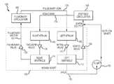
- Another aspect of the present inventionis directed to a system for controlling a blood pump comprising a pump flow estimator for estimating flow rate of the pump, a pump pulse detector for detecting a pulse based on flow estimator output, a negative flow estimator for approximating a negative flow and adjusting a signal from the pulse detector when a valid pulse is detected by the pulse detector, a fault generator for providing notifications to a patient when an invalid pulse is detected by the pulse detector, and a suction detector for evaluating the probability of a suction event based on at least one characteristic of the signal output from the negative flow estimator.
- the systemfurther comprises a speed controller for adjusting a speed of the pump to prevent or mitigate the suction condition.
- FIG. 1is a schematic of a system for controlling a blood pump in accordance with the present invention.
- FIG. 2Ais a flow diagram illustrating a method for detecting and mitigating a suction event.
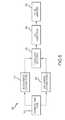
- FIG. 2Bis a block diagram of the components of an exemplary system for implementing the method of FIG. 2A .
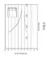
- FIG. 3is a chart showing the coefficients of the quadratic equation for the current pump speed used for flow estimation.
- FIG. 4is a chart showing the power to flow transform for various pump speed values for a given hematocrit.
- FIG. 5is a flow diagram for the method of detecting a pump pulse in accordance with the invention.
- FIG. 6A and FIG. 6Bare line charts showing the method for negative flow approximation in accordance with the invention.
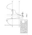
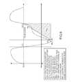
- FIG. 7is a line chart showing the method for identifying the suction marker location (SML) for evaluating the probability of a suction condition in accordance with the invention.
- FIG. 8is another line chart showing the method for evaluating the probability of a suction condition in accordance with the invention.
- FIG. 9is yet another line chart showing the method for evaluating the probability of a suction condition in accordance with the invention.
- FIG. 10is a schematic of a blood pump in accordance with the invention.
- FIG. 11shows an example computing system or device.
- WAIWaveform Asymmetry Index
- SSASystolic Average
- DSAPulse Diastolic Average
- EPFestimated pump flow
- PPMPulses per Minute
- Systolic Pulse IndexIn the systolic segment of the pulse, first rising cross-over, falling cross-over and the marker in the neighborhood of maxima of the EPF pulse are identified and then area from rising cross-over to marker and from the marker to the falling cross-over is calculated. Ratio of these terms provides the Inner Systolic Pulse Index. Furthermore, the Outer Systolic Pulse Index is calculated by calculating the ratio of the area outside the pulse under a bounded rectangle. Note that this term is identified here but not used for suction condition as the Pulse Suction Index (PSI) is found to be a better measure of suction event detection.
- PSIPulse Suction Index
- Diastolic Pulse IndexIn the diastolic segment of the pulse, the falling cross-over, rising cross-over and the marker in the neighborhood of minima of the EPF pulse are identified and then area from falling cross-over to marker and from the marker to the rising cross-over is calculated. Ratio of these terms provides the Inner Diastolic Pulse Index. Furthermore, the Outer Diastolic Pulse Index is calculated by calculating the ratio of the area outside the pulse under a bounded rectangle. Note that this term is identified here but not used for suction condition as the Pulse Suction Index (PSI) is found to be a better measure of suction event detection.
- PSIPulse Suction Index
- any detail discussed with regard to one embodimentmay or may not be present in all contemplated versions of that embodiment.
- any detail discussed with regard to one embodimentmay or may not be present in all contemplated versions of other embodiments discussed herein.
- the absence of discussion of any detail with regard to embodiment hereinshall be an implicit recognition that such detail may or may not be present in any version of any embodiment discussed herein.
- circuits, systems, networks, processes, and other elements in the inventionmay be shown as components in block diagram form in order not to obscure the embodiments in unnecessary detail.
- well-known circuits, processes, algorithms, structures, and techniquesmay be shown without unnecessary detail in order to avoid obscuring the embodiments.
- a processmay correspond to a method, a function, a procedure, a subroutine, a subprogram, etc. When a process corresponds to a function, its termination corresponds to a return of the function to the calling function or the main function.
- machine-readable mediumincludes, but is not limited to transitory and non-transitory, portable or fixed storage devices, optical storage devices, wireless channels and various other mediums capable of storing, containing or carrying instruction(s) and/or data.
- a code segment or machine-executable instructionsmay represent a procedure, a function, a subprogram, a program, a routine, a subroutine, a module, a software package, a class, or any combination of instructions, data structures, or program statements.
- a code segmentmay be coupled to another code segment or a hardware circuit by passing and/or receiving information, data, arguments, parameters, or memory contents. Information, arguments, parameters, data, etc. may be passed, forwarded, or transmitted via any suitable means including memory sharing, message passing, token passing, network transmission, etc.
- embodiments of the inventionmay be implemented, at least in part, either manually or automatically.
- Manual or automatic implementationsmay be executed, or at least assisted, through the use of machines, hardware, software, firmware, middleware, microcode, hardware description languages, or any combination thereof.
- the program code or code segments to perform the necessary tasksmay be stored in a machine readable medium.
- a processor(s)may perform the necessary tasks.
- FIGS. 1 to 9Various aspects are similar to those described in and U.S. Pub. Nos. 2014/0100413 to Casas, 2011/0129373 to Mori, 2014/0155682 to Jeffery et al., and 2013/0225909 to Dormanen et al., and U.S. Pat. No. 7,850,594 to Sutton, U.S. Pat. No. 7,645,225 to Medvedev, U.S. Pat. No. 7,175,588 to Morello, U.S. Pat. No. 6,991,595 to Burke et al., U.S. Pat. No. 5,888,242 to Antaki et al., and U.S. Pat. No. 6,066,086 to Antaki et al., the entire contents of which patents and applications are incorporated herein for all purposes by reference.
- the basic design concept 100includes a pump 105 connected to the left ventricle 110 (or right ventricle 115 or both ventricles) across the aortic valve 120 of a heart 125 .
- the flow through pump 105is estimated using pump parameters which include power/current, speed and a flow map, which allows transformation of inputs like power/current and speed to flow derived from the pump flow characteristics curves (e.g. power/current-flow curves for various speeds and viscosities/hematocrits).
- Heart 125also includes pulmonary valve 130 , tricuspid valve 135 , mitral valve 140 , right atrium 145 , and left atrium 150 .
- FIG. 1Blocks representing pulmonary circulation 180 and systemic circulation 185 are also shown.
- FIG. 2Aillustrates the flow of a method 200 in accordance with embodiments of the invention.
- FIG. 2Billustrates the components of an exemplary physiological control system 250 implementing the suction detection technique in accordance with the inventions. It is contemplated that the components shown in FIG. 2B may be implemented by at least one computing system or device in or as software, firmware, or hardware, and/or any combination thereof. An example of such a computing system or device is shown and described in connection with FIG. 11 below. Example functions for suction detection and mitigation using the illustrated system will now be described with respect to an exemplary left ventricular assist device (LVAD).
- LVADleft ventricular assist device
- the pump flow estimator component 255takes various pump and system parameters like pump speed, pump current, pump voltage, pump power transfer characteristics and other system or vital-related parameters like Hematocrit to provide the estimated flow output.
- the pump characteristicscan be used to determine flow in various ways.
- pump power and speed inputsare used to determine the estimated flow.
- Other methods suitable for obtaining the flow waveformare acceptable as long as the methods can provide real-time flow estimation within the pump requirements, e.g., at 100 Hz and with a tolerance of +/ ⁇ 0.5 LPM, including a direct flow measurement.
- the method described hereindiffers from conventional techniques in several respects.
- the coefficients of the quadratic equation for the current pump speed as shown in the chart in FIG. 3are interpolated.
- the x ⁇ 1 trendis the topmost trend
- the x ⁇ 2 trendis the middle trend
- the x ⁇ 0 trendis the bottommost trend.
- the chart in FIG. 4shows the power to flow transform for various pump speed values for a given Hematocrit.
- the 1500 Hematocrit trenddeduced by collecting power to flow transforms for various blood hematocrit values and adjusted accordingly in real-time.
- a pump pulse detector 260takes the estimated flow from flow estimator 205 as an input and identifies pulses in the flow measurement to allow data analysis at individual pulse level.
- FIG. 5demonstrates one possible method 500 of detecting pulses.
- pump flowis estimated.
- the estimated flowis then subjected to an under damped low pass filter (block 515 ), and an over damped low pass filter (block 520 ).
- the over damped and under damped signalsare superimposed on each other and cross over points are detected at block 530 .
- Lag correctionis conducted at block 540 , and the resulting pulse is then analyzed at block 550 .
- RCO 1shows the start of the pulse and at the second rising edge is depicted as RCO 2 shows the end of the pulse.
- RCO 2shows the end of the pulse.
- FCOThe cross over point identified at the falling edge of the pulse as FCO and shows the end of systole and the beginning of the diastole.
- Pulse detector 260monitors the pulse detector output and validates if the output pulse satisfies the acceptance criteria to ensure that a valid pulse is passed along.
- the acceptance criteriamay include, but is not limited to, peak-to-peak flow, minimum flow, minimum and maximum pulse frequency or period, etc. If the pulse validation is successful, it passes it on to a negative flow estimator 265 at block 220 . Otherwise, it transfers control to the fault generator 280 at block 225 .
- the exemplary physiological control applicationcalled for a minimum peak-to-peak pulse of at least 1 LPM, a mean flow of at least 1 LPM, a minimum pulse period of 333 msec ( ⁇ 180 beats/min), and a maximum pulse period of 1.5 sec ( ⁇ 40 beats/min). If the pulse does not meet these criteria, it will raise fault at block 225 .
- Negative flow approximationis generally necessary to overcome the limitation of using the pump as a flow sensor. Additionally, conventional pump systems do not have a way to measure negative flows. Negative flow approximator 265 takes the individual pulse from the pulse detector 260 as an input and tests it to see if it needs negative flow correction. In cases where the correction is needed, approximator 265 adjusts the signal and passes it on to the next component in the process.
- Block 220provides an approximation which may or may not reflect the true measurement. Accordingly, FIG. 6A and FIG. 6B show a type of pulse and the correction which may be made to approximate the negative flow.
- negative flow approximationis based on an extended negative pulse where the diastolic phase of the pulse shows minimal noise.
- negative flow approximationis based on an inverted negative pulse where the diastolic phase of the pulse shows detectable noise.
- a suction detector 270evaluates the pulse characteristic from negative flow approximator 265 and provides a quantifiable measure for the existence of the suction condition using the method described below. For the exemplary application, ⁇ >75% is used as a determining factor for the declaration of the presence of suction.
- the value from the Suction Detector 270is passed on to a suction speed controller 275 to make appropriate adjustments to the speed according the pulse suction index ⁇ output.
- the index PSI/SI/ ⁇is calculated by identifying a suction marker which is located in the diastolic phase of the pump flow pulse as shown in FIG. 7 .
- the suction markeris located using the midpoint in the diastolic phase as a reference point approaching towards the minima of the diastolic segment of the pump flow pulse such that a minimum suction marker flow (SMF) threshold SMF Min is reached.
- SMFsuction marker flow
- SMLSuction Marker Location
- SMLis used to identify the primary suction probability of the suction for given pulse using the formula given below.
- FIG. 8elaborates on these terms graphically.
- Suction Probability SPPump Pulse Suction Index PSI or Suction Index SI or ‘ ⁇ ’ is derived as follows.
- FIG. 9elaborates on the above terms graphically.
- suction speed controller 275takes the suction index ⁇ and low pump speed limit as inputs, and based on current pump speed and historical presence of suction condition, makes adjustments to the pump speed necessary to mitigate a suction condition or to recover the clinician specified patient speed while minimizing the introduction of suction events over time as the speed is restored to its set-point.
- a binary search strategymay be used for its fast convergence to the optimal speed set-point along with a maximum upper bound for the speed set-point step change.
- Controller 275can also keep track of the trends of Estimated Pump Flow, Diastolic Averages, Pulsatility Index, Flow Waveform Magnitude Asymmetry and Pulse Magnitude.
- the controller 275may also validate the presence of suction and detection of conditions like inflow/outflow obstruction.
- a fault generator 280is intended to provide visual/audible notifications to the patient when an invalid or no pulse is detected.
- the fault generator 280may also provide a notification when a suction condition is detected that needs mitigation. These conditions may include low/no mean flow, low peak-to-peak flow, pulse rate too high or too low, suction detected, unmitigated suction and inflow/outflow obstruction conditions.
- the determination and selection of faults to the patientis a risk management activity.
- the criteria for notification to the patientmay be pre-selected by a risk management team.
- the methods and systems described herein for suction detection and mitigationprovides several advantages over existing techniques.
- the inventionreduces the probability of false positives for suction detection.
- the inventionprovides a bounded unit less quantity for the probability of the presence of suction condition without the complications of conventional techniques.
- the inventive techniquereduces or eliminates the need for processing intensive signal analysis, pulse recognition based on correlation and harmonic analysis schemes, or pulse recognition based on a database of known suction waveforms and matching of those waveforms against the input pump flow/power/current signal.
- the inventive system described aboveanalyzes the features of the pulse so that even the detection of intermittent conditions is possible.
- the mitigation in response to the presence of a suction conditionis optimized for its response time and minimizes the need for clinician involvement compared to existing approaches. It also minimizes the number of necessary patient visits in cases where there is a recovery from patient's physiological conditions causing suction condition over time.
- FIG. 10shows a schematic of a blood pump 1000 in accordance with some embodiments of the invention.
- the techniques of the inventionmay be used in connection with a blood pump of this type, among others.
- Blood pump 1000includes a housing 1002 having a blood inlet port 1006 and a blood outlet port (not shown) via conduit 1007 ; a pump unit 1012 including an impeller 1008 which has a plurality of magnetic materials (magnetic material bodies or pieces) 1025 and which rotates within the housing to feed blood; and an impeller rotational torque generation section 1013 for rotating the impeller.
- Housing 1002includes a plurality of magnetic members 1054 embedded between the impeller 1008 and the impeller rotational torque generation section 1013 for transmitting a magnetically attractive force generated by the impeller rotational torque generation section 1013 to the magnetic material bodies 1025 of the impeller.
- the magnetic material bodies 1054are embedded in the housing 1002 (second housing member 1004 ) so that the magnetic material bodies 1054 are positioned in respective recesses in the housing 1002 (second housing member 1004 ) and so that the magnetic material bodies 1054 form a part of the housing 1002 or second housing member 1004 (e.g., the material forming the second housing member 1004 contacts and surrounds at least a portion of the magnetic material bodies 1054 as shown in FIG. 10 ).
- the blood pump 1000includes a non-contact bearing mechanism for rotating the impeller without contacting within the housing when the impeller is rotated by the impeller rotational torque generation section 1013 .
- the blood pump apparatus 1000 in the present embodimentincludes the housing 1002 , the pump unit 1012 composed of the impeller 1008 accommodated in the housing 1002 , and the impeller rotational torque generation section 1013 for rotating the impeller.
- the impeller rotational torque generation section 1013is attachable to and detachable from the pump unit 1012 . With the impeller rotational torque generation section 1013 thus attachable to and detachable from the pump unit 1012 , the impeller rotational torque generation section 1013 having no blood contact part during use can be reused, so that only the pump unit 1012 which has a blood circulating part is disposable.
- the housing 1002includes: a first housing member 1003 having the blood inlet port 1006 and a recess for accommodating an upper portion of the impeller 1008 ; and a second housing member 1004 having the blood outlet port and a recess for accommodating a lower portion of the impeller 1008 .
- the housing 1002is formed by combining the first housing member 1003 and the second housing member 1004 with each other.
- the interior of the housing 1002is provided with or forms a blood chamber 1024 through which the blood inlet port 1006 and the blood outlet port communicate with each other.
- the blood inlet port 1006projects substantially perpendicularly from around the center of the upper surface of the housing 1002 (the first housing member 1003 ).
- the blood inlet port 1006is not limited to the straight pipe as illustrated, but may be a curved pipe or a bent pipe.
- the blood outlet portprojects in a tangential direction from the side surface of the housing 1002 , which is formed in a substantially hollow cylindrical shape.
- the blood outflow passageis of a double volute structure divided into two parts in the, but it may be of a single volute structure or of a voluteless structure.
- the housing 1002includes the plurality of magnetic members 1054 embedded between the impeller 1008 and the impeller rotational torque generation section 1013 for transmitting a magnetically attractive force generated by the impeller rotational torque generation section 1013 to the magnetic material bodies 1025 of the impeller.
- the plurality of magnetic members 1054are embedded in the second housing member 1004 (more specifically, in the bottom wall of the second housing member 1004 ). It is particularly preferable that the magnetic members 1054 are so embedded as not to be exposed to the inside of the blood chamber 1024 , as in the pump apparatus 1 according to the present embodiment.
- As the magnetic member 1054a ferromagnetic material is used.
- the housing 1002specifically the first housing member 1003 and the second housing member 1004 , are formed of synthetic resin or metal.
- the first housing member 1003 and the second housing member 1004have peripheral parts which make surface contact with each other, as shown in FIG. 10 .
- the impeller 1008is contained in the housing 1002 . Specifically, as shown in FIG. 10 , a disk-shaped impeller 1008 provided with a centrally located through-hole is contained in the blood chamber 1024 formed inside the housing 1002 .
- the impeller 1008includes an annular member (lower shroud) 1027 forming a lower surface, an annular member (upper shroud) 1028 provided with an opening in its center and forming an upper surface, and a plurality of (for example, seven) vanes between the two members or shrouds. Between the lower shroud and the upper shroud, there are formed a plurality of (for example, seven) blood flow channels, each partitioned by the adjacent vanes.
- the blood flow channelscommunicate with the central opening of the impeller 1008 , and extend to the outer peripheral edge while gradually increasing in width, starting from the central opening of the impeller 1008 .
- the vanesare each formed between the adjacent blood flow channels.
- the blood flow channels and the vanesare provided at regular angular intervals and in substantially the same shape, respectively.
- the impeller 8has a plurality of (for example, six) magnetic material bodies or pieces 1025 (permanent magnets; driven magnets) embedded therein.
- the magnetic material bodies 1025are embedded in the lower shroud 1027 .
- the magnetic material bodies 1025 (permanent magnets) thus embeddedare attracted toward the impeller rotational torque generation section 1013 side by stators 1051 of the impeller rotational torque generation section 1013 and, also, receive a rotation torque of the impeller rotational torque generation section 1013 through the magnetic members embedded in the housing 1002 (the second housing member 1004 ).
- the magnetic material bodies 1025include a circle, a sector and, further, a ring (an integral form in which N poles and S poles are alternately polarized).
- the impeller membersare formed of a highly corrosion-resistant metal (titanium, stainless steel SUS316L, or the like) or synthetic resin. As the synthetic resin here, those which have been described above as material for the housing can be preferably used.
- the blood pump apparatus 1000 disclosed hereincludes a non-contact bearing mechanism for rotating the impeller without contacting the inner surface of the housing when the impeller is rotated by the impeller rotational torque generation section 1013 .
- the non-contact bearing mechanismis composed of grooves for hydrodynamic bearing 1048 provided in the inner surface of the housing 1002 on the impeller rotational torque generation section 1013 side, in other words in a surface (bottom wall surface) of the recess in the second housing member 1004 .
- the impelleris rotated, without contact, under a dynamic pressure bearing effect offered by a dynamic pressure generated between a surface (groove for hydrodynamic bearing formed part) 1042 in which the grooves for hydrodynamic bearing are formed and the impeller 1008 , by rotation thereof at a rotating speed of not less than a predetermined value.
- each of the grooves for hydrodynamic bearing 1048has its one end on the peripheral edge (circumference) of a circular part slightly outwardly spaced from the center of the surface of the recess in the second housing member, and extends therefrom nearly to the outer edge of the recess surface in a vortex form (in other words, in a curved form) while gradually increasing in width.
- the grooves for hydrodynamic bearing 1048are plural in number, are the same shape (inclusive of substantially the same shape), and are arranged at regular (equal) intervals (inclusive of substantially equal intervals).
- the grooves for hydrodynamic bearing 1048are each a recess, the depth of which is preferably about 0.005 to 0.4 mm.
- the number of the grooves for hydrodynamic bearing 1048is preferably about 6 to 36. In the present example, twelve grooves for hydrodynamic bearing are arranged at regular (equal) angular intervals about the center axis of the impeller.
- the grooves for hydrodynamic bearing 1048 in the pump apparatus disclosed herehave a so-called inward spiral groove shape.
- the impeller 1008is attracted toward the impeller rotational torque generation section 1013 side at the time of rotation.
- the presence of the groove for hydrodynamic bearing formed part as above-mentionedhelps ensure that, by the dynamic pressure bearing effect provided between the groove for hydrodynamic bearing formed part of the housing and the bottom surface of the impeller 1008 (or between the groove for hydrodynamic bearing formed part of the impeller and the housing inner surface), the impeller 1008 is separated from the housing inner surface, and is rotated without contact, whereby a blood flow channel is secured between the lower surface of the impeller and the housing inner surface, and blood stagnation between these surfaces and the resultant thrombus formation are prevented from occurring. Further, in a normal condition, the groove for hydrodynamic bearing formed part exhibits a stirring action between the lower surface of the impeller and the housing inner surface, so that partial blood stagnation between these surfaces is inhibited or prevented from occurring.
- the groove for hydrodynamic bearing formed partmay be provided in that surface of the impeller 1008 which is on the impeller rotational torque generation section side, not on the housing side.
- the same configuration as that of the groove for hydrodynamic bearing formed part described aboveis preferably adopted.
- the grooves for hydrodynamic bearingmay be provided in that surface of the impeller 1008 which is on the impeller rotational torque generation section 1013 side (in other words, in the bottom surface of the impeller 1008 ).
- the pump apparatus 1000 in the present embodimentcan be constructed so that the housing inner surface on the opposite side to the impeller rotational torque generating part side (i.e., the surface of the recess in the first housing member 1003 ) may also be provided with a groove for hydrodynamic bearing formed part (second groove for hydrodynamic bearing formed part) having a plurality of grooves for hydrodynamic bearing (second grooves for hydrodynamic bearing) 1033 .
- the impeller rotational torque generation section 1013 of the blood pump apparatus 1000 according to the present embodimentis composed of a motor stator 50 including a plurality of stators 1051 disposed on the circumference of a circle (arranged in an annular form).
- a third housing member 1005is provided with an annular recess (doughnut-shaped recess), and the plurality of stators 1051 are contained in the third housing member 1005 , in the state of being arranged in an annular pattern (doughnut-like pattern).
- the stator 1051has a stator core 1053 and a stator coil 1052 wound around the stator core 1053 .
- six stators 1051form the stator motor 1050 .
- stator coil 1052As the stator coil 1052 , a multilayer wound stator coil is used. With the direction of current flowing in the stator coils 1052 of the respective stators 1051 switched over or alternating a rotating magnetic field is generated, by which the impeller is attracted and rotated.
- the respective magnetic members 1054 of the housing 1002are so disposed as to be located on, or in overlying relation to, the stator cores 1053 of the respective stators 1051 described above. That is, each of the plurality of magnetic members 1054 is positioned in circumferential alignment with one of the stator cores 1053 of the stators 1051 .
- the stator cores 1053 in the present embodimentare each sector-shaped a, and correspondingly, the magnetic members 1054 are also each sector-shaped.
- the magnetic members 1054are slightly greater in size than the stator cores 1053 .
- each of the magnetic members 1054 of the housing 1002makes direct contact with the stator core 1053 of each of the stators 1051 . More specifically, in this pump apparatus 1000 , an upper end portion of the stator core 1053 projects upwardly slightly beyond the stator coil 1052 , and the projecting portion is exposed.
- the magnetic member 1054is so embedded in the second housing member 1004 that its lower surface is exposed; further, the portion where the lower surface of the magnetic member 1054 is exposed forms a recess in which the projecting portion of the stator core 1053 is accommodated. Therefore, the magnetic member 1054 and the stator core 1053 are in contact with each other. This helps ensure that a magnetic force generated in the stator 1051 can be securely transmitted to the magnetic member 1054 .
- the pump unit 1012 and the impeller rotational torque generation section 1013can be attached to and detached from each other, and both of them have a connecting mechanism.
- the second housing member of the pump unit 1012is provided at its bottom surface with a first engaging part (a recess) 1045
- the housing 1005 of the impeller rotational torque generation section 1013is provided with a second engaging part (specifically, a projection) 1055 which engages the first engaging part (recess) 1045 .
- the engagement between the first engaging part (recess) 1045 of the pump unit 1012 and the second engaging part (projection) 1055 of the impeller rotational torque generation section 1013connects the units to each other.
- FIG. 11shows an example computer system or device 1100 in accordance with the disclosure.
- An example of a computer system or deviceincludes a medical device, a desktop computer, a laptop computer, a tablet computer, and/or any other type of machine configured and/or arranged for performing calculations.
- the example computer device 1100may be configured and/or arranged to perform and/or include instructions that, when executed, cause the computer system 1100 to perform a method for or of detecting a suction event of a blood pump such as that discussed in the context of the present disclosure.
- the example computer device 1100may be configured to perform and/or include instructions that, when executed, cause the computer system 1100 to perform at least one of the following steps: determining a flow waveform of the pump; identifying pulses in the flow waveform; determining a negative flow pulse based on a valid identification of a pulse; and evaluating a characteristic of the pulse for an existence of a suction condition.
- the example computer device 1100may be configured and/or arranged to perform and/or include instructions that, when executed, cause the computer system 1100 to select a pulse segmentation from the group consisting of: The Pulse Average, The Pulse Minima (Turf), The Pulse Maxima (Crest), The pulse falling cross-over point, The Systolic Average (SSA), The Diastolic Average (DSA), The Systolic Pulse Index (SPI), The Diastolic Pulse Index (DPI), The Pulse Flow Index (PFI), The Negative Flow Correction, The Pulse Asymmetry Index, The Pulse Suction Index ( ⁇ ), The Pulse Duty Cycle (PDC), The Pulse Frequency (PHZ), and a combination of the same.
- the Pulse AverageThe Pulse Minima (Turf), The Pulse Maxima (Crest), The pulse falling cross-over point
- example computer device 1100may be configured and/or arranged to perform and/or include instructions that, when executed, cause the computer system 1100 to implement a method of or for negative flow approximation, wherein the diastolic segment of the pump flow pulse is used to determine the type of approximation and correction to determined flow is made based on the type of approximation identified.
- the example computer device 1100may be configured and/or arranged to perform and/or include instructions that, when executed, cause the computer system 1100 to determine a quantity of the suction condition, and wherein the quantity is named after the Greek Symbol ( ⁇ ) pronounced as PSI and used as an acronym with the definition of Pulse Suction Index (PSI).
- ⁇Pulse Suction Index
- example computer device 1100may be configured and/or arranged to perform and/or include instructions that, when executed, cause the computer system 1100 to implement a method of or for a method of calculating a pulse suction index ( ⁇ ) according to the formula:
- example computer device 1100may be configured to perform and/or include instructions that, when executed, cause the computer system 1100 to use a binary search to increase or decrease the pump speed when suction criteria is met, and the step change of the pump speed of the binary search is bounded by an upper limit identified as safe for the patient population.
- example computer device 1100may be configured to perform and/or include instructions that, when executed, cause the computer system 1100 to derive an indication wherein an increase in MIN(DSA) with the an increase in MIN(DSA) with the decrease in speed may additionally indicate recovery from suction condition.
- example computer device 1100may be configured and/or arranged to perform and/or include instructions that, when executed, cause the computer system 1100 to derive an indication wherein a decrease in MEAN(PAI) with the decrease in speed may additionally indicate recovery from suction condition.
- example computer device 1100may be configured and/or arranged to perform and/or include instructions that, when executed, cause the computer system 1100 to derive an indication wherein a decrease in MEAN(DPI) with the decrease in speed may additionally indicate recovery from suction condition.
- example computer device 1100may be configured and/or arranged to perform and/or include instructions that, when executed, cause the computer system 1100 to derive an indication wherein a decrease in PSI( ⁇ ) with the decrease in speed will most likely indicate recovery from suction condition.
- the example computer device 1100may be configured and/or arranged to perform and/or include instructions that, when executed, cause the computer system 1100 to determine or identify or detect that a lowest allowable pump speed for recovery from suction condition is based on a Low Speed Limit.
- the Low Speed Limitis based on an input from a clinician as detected by the device 1100 .
- the example computer device 1100may be configured and/or arranged to perform and/or include instructions that, when executed, cause the computer system 1100 to implement the step of evaluating by: locating a suction marker reference point based on a midpoint in the diastolic phase; identifying a suction marker location where a suction marker flow minimum is reached; and using the suction marker location to identify a probability of a suction condition.
- example computer device 1100may be configured and/or arranged to perform and/or include instructions that, when executed, cause the computer system 1100 to implement a step of decreasing a speed of the pump in response to identification of the existence of a suction condition.
- the computer device 1100is shown comprising hardware elements that may be electrically coupled via a bus 1102 (or may otherwise be in communication, as appropriate).
- the hardware elementsmay include a processing unit with one or more processors 1104 , including without limitation one or more general-purpose processors and/or one or more special-purpose processors (such as digital signal processing chips, graphics acceleration processors, and/or the like); one or more input devices 1106 , which may include without limitation a remote control, a mouse, a keyboard, and/or the like; and one or more output devices 1108 , which may include without limitation a presentation device (e.g., television), a printer, and/or the like.
- a presentation devicee.g., television
- the computer system 1100may further include (and/or be in communication with) one or more non-transitory storage devices 1110 , which may comprise, without limitation, local and/or network accessible storage, and/or may include, without limitation, a disk drive, a drive array, an optical storage device, a solid-state storage device, such as a random access memory, and/or a read-only memory, which may be programmable, flash-updateable, and/or the like.
- Such storage devicesmay be configured to implement any appropriate data stores, including without limitation, various file systems, database structures, and/or the like.
- the computer device 1100might also include a communications subsystem 1112 , which may include without limitation a modem, a network card (wireless and/or wired), an infrared communication device, a wireless communication device and/or a chipset such as a BluetoothTM device, 1102.11 device, WiFi device, WiMax device, cellular communication facilities such as GSM (Global System for Mobile Communications), W-CDMA (Wideband Code Division Multiple Access), LTE (Long Term Evolution), etc., and/or the like.
- the communications subsystem 1112may permit data to be exchanged with a network (such as the network described below, to name one example), other computer systems, and/or any other devices described herein.
- the computer system 1100will further comprise a working memory 1114 , which may include a random access memory and/or a read-only memory device, as described above.
- the computer device 1100also may comprise software elements, shown as being currently located within the working memory 1114 , including an operating system 1116 , device drivers, executable libraries, and/or other code, such as one or more application programs 1118 , which may comprise computer programs provided by various embodiments, and/or may be designed to implement methods, and/or configure systems, provided by other embodiments, as described herein.
- an operating system 1116operating system 1116
- device driversexecutable libraries
- application programs 1118which may comprise computer programs provided by various embodiments, and/or may be designed to implement methods, and/or configure systems, provided by other embodiments, as described herein.
- codemay be used to configure and/or adapt a general purpose computer (or other device) to perform one or more operations in accordance with the described methods.
- a set of these instructions and/or codemight be stored on a non-transitory computer-readable storage medium, such as the storage device(s) 1110 described above.
- the storage mediummight be incorporated within a computer system, such as computer system 1100 .
- the storage mediummight be separate from a computer system (e.g., a removable medium, such as flash memory), and/or provided in an installation package, such that the storage medium may be used to program, configure, and/or adapt a general purpose computer with the instructions/code stored thereon.
- These instructionsmight take the form of executable code, which is executable by the computer device 1100 and/or might take the form of source and/or installable code, which, upon compilation and/or installation on the computer system 1100 (e.g., using any of a variety of generally available compilers, installation programs, compression/decompression utilities, etc.), then takes the form of executable code.
- some embodimentsmay employ a computer system (such as the computer device 1100 ) to perform methods in accordance with various embodiments of the disclosure. According to a set of embodiments, some or all of the procedures of such methods are performed by the computer system 1100 in response to processor 1104 executing one or more sequences of one or more instructions (which might be incorporated into the operating system 1116 and/or other code, such as an application program 1118 ) contained in the working memory 1114 . Such instructions may be read into the working memory 1114 from another computer-readable medium, such as one or more of the storage device(s) 1110 . Merely by way of example, execution of the sequences of instructions contained in the working memory 1114 may cause the processor(s) 1104 to perform one or more procedures of the methods described herein.
- a computer systemsuch as the computer device 1100
- machine-readable mediumand “computer-readable medium,” as used herein, may refer to any non-transitory medium that participates in providing data that causes a machine to operate in a specific fashion.
- various computer-readable mediamight be involved in providing instructions/code to processor(s) 1104 for execution and/or might be used to store and/or carry such instructions/code.
- a computer-readable mediumis a physical and/or tangible storage medium.
- Such a mediummay take the form of a non-volatile media or volatile media.
- Non-volatile mediamay include, for example, optical and/or magnetic disks, such as the storage device(s) 1110 .
- Volatile mediamay include, without limitation, dynamic memory, such as the working memory 1114 .
- Example forms of physical and/or tangible computer-readable mediamay include a floppy disk, a flexible disk, hard disk, magnetic tape, or any other magnetic medium, a compact disc, any other optical medium, ROM (Read Only Memory), RAM (Random Access Memory), and etc., any other memory chip or cartridge, or any other medium from which a computer may read instructions and/or code.
- Various forms of computer-readable mediamay be involved in carrying one or more sequences of one or more instructions to the processor(s) 1104 for execution.
- the instructionsmay initially be carried on a magnetic disk and/or optical disc of a remote computer.
- a remote computermight load the instructions into its dynamic memory and send the instructions as signals over a transmission medium to be received and/or executed by the computer system 1100 .
- the communications subsystem 1112(and/or components thereof) generally will receive signals, and the bus 1102 then might carry the signals (and/or the data, instructions, etc. carried by the signals) to the working memory 1114 , from which the processor(s) 1104 retrieves and executes the instructions.
- the instructions received by the working memory 1114may optionally be stored on a non-transitory storage device 1110 either before or after execution by the processor(s) 1104 .
- computer device 1100can be distributed across a network. For example, some processing may be performed in one location using a first processor while other processing may be performed by another processor remote from the first processor. Other components of computer system 1100 may be similarly distributed. As such, computer device 1100 may be interpreted as a distributed computing system that performs processing in multiple locations. In some instances, computer system 1100 may be interpreted as a single computing device, such as a distinct laptop, desktop computer, or the like, depending on the context.
Landscapes
- Health & Medical Sciences (AREA)
- Heart & Thoracic Surgery (AREA)
- Engineering & Computer Science (AREA)
- Cardiology (AREA)
- Biomedical Technology (AREA)
- Mechanical Engineering (AREA)
- Anesthesiology (AREA)
- Hematology (AREA)
- Life Sciences & Earth Sciences (AREA)
- Animal Behavior & Ethology (AREA)
- General Health & Medical Sciences (AREA)
- Public Health (AREA)
- Veterinary Medicine (AREA)
- Fluid Mechanics (AREA)
- Physics & Mathematics (AREA)
- External Artificial Organs (AREA)
Abstract
Description
F=Ap2+Bp+C
Where,
- Where,
- SP=Suction Probability.
- SPR1=
Suction Probability Reference 1 is the time between SML and FCO. - SPR2=
Suction Probability Reference 2 is the pump pulse time period.
- Where,
- Ψ=Suction Index, %
- SP=Suction Probability.
- PAR1=
Pulse Area Reference 1 is the area defined by the pulse region overlapping the area PAR2. - PAR2=
Pulse Area Reference 2 is the right triangular area defined time period between RCO2and SML and the difference of flow magnitude at RCO2and MNL.
F=Ap2+Bp+C
- F=Flow Rate (LPM)
- p=Pump Power (W) adjusted for hematocrit (This could also be based on current)
- A=Interpolated X2 Polynomial coefficient for the given pump speed.
- B=Interpolated X1 Polynomial coefficient for the given pump speed.
- C=Interpolated X0 Polynomial coefficient for the given pump speed.
- Ψ=Suction Index, %
- SP=Suction Probability
- PAR1=
Pulse Area Reference 1 is the area defined by the pulse region overlapping the area PAR2 - PAR2=
Pulse Area Reference 2 is the right triangular area defined time period between - RCO2and SML and the difference of flow magnitude at RCO2and MNL
Claims (14)
F=Ap2+Bp+C
F=Ap2+Bp+C
Priority Applications (3)
| Application Number | Priority Date | Filing Date | Title |
|---|---|---|---|
| US14/834,757US9623161B2 (en) | 2014-08-26 | 2015-08-25 | Blood pump and method of suction detection |
| EP15836177.4AEP3185925B1 (en) | 2014-08-26 | 2015-08-26 | Blood pump and method of suction detection |
| PCT/US2015/046846WO2016033133A1 (en) | 2014-08-26 | 2015-08-26 | Blood pump and method of suction detection |
Applications Claiming Priority (2)
| Application Number | Priority Date | Filing Date | Title |
|---|---|---|---|
| US201462041910P | 2014-08-26 | 2014-08-26 | |
| US14/834,757US9623161B2 (en) | 2014-08-26 | 2015-08-25 | Blood pump and method of suction detection |
Publications (2)
| Publication Number | Publication Date |
|---|---|
| US20160058929A1 US20160058929A1 (en) | 2016-03-03 |
| US9623161B2true US9623161B2 (en) | 2017-04-18 |
Family
ID=55400471
Family Applications (1)
| Application Number | Title | Priority Date | Filing Date |
|---|---|---|---|
| US14/834,757ActiveUS9623161B2 (en) | 2014-08-26 | 2015-08-25 | Blood pump and method of suction detection |
Country Status (3)
| Country | Link |
|---|---|
| US (1) | US9623161B2 (en) |
| EP (1) | EP3185925B1 (en) |
| WO (1) | WO2016033133A1 (en) |
Cited By (14)
| Publication number | Priority date | Publication date | Assignee | Title |
|---|---|---|---|---|
| US20170185054A1 (en)* | 2015-12-28 | 2017-06-29 | Heartware, Inc. | Pump motor control with adaptive startup |
| US10881770B2 (en) | 2018-01-10 | 2021-01-05 | Magenta Medical Ltd. | Impeller for blood pump |
| US10947986B2 (en)* | 2018-07-11 | 2021-03-16 | Ch Biomedical (Usa) Inc. | Compact centrifugal pump with magnetically suspended impeller |
| US11191944B2 (en) | 2019-01-24 | 2021-12-07 | Magenta Medical Ltd. | Distal tip element for a ventricular assist device |
| US11260212B2 (en) | 2016-10-25 | 2022-03-01 | Magenta Medical Ltd. | Ventricular assist device |
| US11291826B2 (en) | 2018-01-10 | 2022-04-05 | Magenta Medical Ltd. | Axially-elongatable frame and impeller |
| US11413445B2 (en) | 2019-03-12 | 2022-08-16 | Heartware, Inc. | Method of monitoring health conditions of a patient having an implantable blood pump |
| US11617878B2 (en) | 2020-01-21 | 2023-04-04 | Medtronic, Inc. | Diagnostic metric for cumulative presence of suction conditions |
| US11786721B2 (en) | 2021-01-05 | 2023-10-17 | Medtronic, Inc. | Sleep mode and do-not-disturb mode for a left ventricular assist device |
| US12102814B2 (en) | 2020-04-16 | 2024-10-01 | Heartware, Inc. | Algorithm for detecting and presenting suction in down-sampled MCS log files |
| US12128227B2 (en) | 2020-04-07 | 2024-10-29 | Magenta Medical Ltd. | Manufacture of an impeller |
| US12341463B2 (en) | 2022-06-06 | 2025-06-24 | Star Bp, Inc. | Blood pump controller and system |
| US12337164B2 (en) | 2019-03-12 | 2025-06-24 | Heartware, Inc. | HVAD flow pulsatility tracker |
| US12440663B2 (en) | 2022-04-18 | 2025-10-14 | Magenta Medical Ltd. | Curved tube for a ventricular assist device |
Families Citing this family (40)
| Publication number | Priority date | Publication date | Assignee | Title |
|---|---|---|---|---|
| US8562507B2 (en) | 2009-02-27 | 2013-10-22 | Thoratec Corporation | Prevention of aortic valve fusion |
| JP5577506B2 (en) | 2010-09-14 | 2014-08-27 | ソーラテック コーポレイション | Centrifugal pump device |
| CA2811606C (en) | 2010-09-24 | 2018-10-23 | Thoratec Corporation | Generating artificial pulse |
| EP2693609B1 (en) | 2011-03-28 | 2017-05-03 | Thoratec Corporation | Rotation and drive device and centrifugal pump device using same |
| US9371826B2 (en) | 2013-01-24 | 2016-06-21 | Thoratec Corporation | Impeller position compensation using field oriented control |
| US9556873B2 (en) | 2013-02-27 | 2017-01-31 | Tc1 Llc | Startup sequence for centrifugal pump with levitated impeller |
| US10052420B2 (en) | 2013-04-30 | 2018-08-21 | Tc1 Llc | Heart beat identification and pump speed synchronization |
| US9623161B2 (en) | 2014-08-26 | 2017-04-18 | Tc1 Llc | Blood pump and method of suction detection |
| EP3256183B1 (en) | 2015-02-11 | 2025-08-13 | Tc1 Llc | Heart beat identification and pump speed synchronization |
| US10371152B2 (en) | 2015-02-12 | 2019-08-06 | Tc1 Llc | Alternating pump gaps |
| EP3256185B1 (en) | 2015-02-12 | 2019-10-30 | Tc1 Llc | System and method for controlling the position of a levitated rotor |
| EP3256184B1 (en) | 2015-02-13 | 2020-04-08 | Tc1 Llc | Impeller suspension mechanism for heart pump |
| US20170016449A1 (en)* | 2015-07-14 | 2017-01-19 | Hamilton Sundstrand Corporation | Axial-flux induction motor pump |
| US10117983B2 (en) | 2015-11-16 | 2018-11-06 | Tc1 Llc | Pressure/flow characteristic modification of a centrifugal pump in a ventricular assist device |
| US10780209B2 (en) | 2017-03-29 | 2020-09-22 | Tc1 Llc | Adjusting pump protocol based on irregular heart rhythm |
| WO2018183568A1 (en) | 2017-03-29 | 2018-10-04 | Tc1 Llc | Pressure sensing ventricular assist devices and methods of use |
| US11065436B2 (en) | 2017-03-29 | 2021-07-20 | Tc1 Llc | Communication methods and architecture for heart treatment systems |
| CA3066361A1 (en) | 2017-06-07 | 2018-12-13 | Shifamed Holdings, Llc | Intravascular fluid movement devices, systems, and methods of use |
| EP4066870B1 (en) | 2017-06-15 | 2023-05-31 | Chiaro Technology Limited | Breast pump system |
| WO2019094963A1 (en) | 2017-11-13 | 2019-05-16 | Shifamed Holdings, Llc | Intravascular fluid movement devices, systems, and methods of use |
| CN112004563B (en) | 2018-02-01 | 2024-08-06 | 施菲姆德控股有限责任公司 | Intravascular blood pump and methods of use and manufacture |
| EP4461341A3 (en) | 2018-03-15 | 2025-01-15 | Tc1 Llc | Systems for preventing right heart failure |
| US11167123B2 (en) | 2018-03-19 | 2021-11-09 | Tc1 Llc | Coordinated ventricular assist and cardiac rhythm management devices and methods |
| US11241570B2 (en) | 2018-07-17 | 2022-02-08 | Tc1 Llc | Systems and methods for inertial sensing for VAD diagnostics and closed loop control |
| US12161857B2 (en) | 2018-07-31 | 2024-12-10 | Shifamed Holdings, Llc | Intravascular blood pumps and methods of use |
| WO2020073047A1 (en) | 2018-10-05 | 2020-04-09 | Shifamed Holdings, Llc | Intravascular blood pumps and methods of use |
| US20200164116A1 (en)* | 2018-11-26 | 2020-05-28 | Alcon Inc. | Methods and systems for controlling aspiration flow rate |
| CN110464895B (en)* | 2019-06-26 | 2022-02-22 | 上海微创心力医疗科技有限公司 | Magnetic liquid suspension type blood pump |
| WO2021011473A1 (en) | 2019-07-12 | 2021-01-21 | Shifamed Holdings, Llc | Intravascular blood pumps and methods of manufacture and use |
| US11654275B2 (en) | 2019-07-22 | 2023-05-23 | Shifamed Holdings, Llc | Intravascular blood pumps with struts and methods of use and manufacture |
| WO2021062265A1 (en) | 2019-09-25 | 2021-04-01 | Shifamed Holdings, Llc | Intravascular blood pump systems and methods of use and control thereof |
| US12121713B2 (en) | 2019-09-25 | 2024-10-22 | Shifamed Holdings, Llc | Catheter blood pumps and collapsible blood conduits |
| EP4501393A3 (en) | 2019-09-25 | 2025-04-09 | Shifamed Holdings, LLC | Catheter blood pumps and collapsible pump housings |
| EP4072650A4 (en) | 2019-12-11 | 2024-01-10 | Shifamed Holdings, LLC | Descending aorta and vena cava blood pumps |
| US11504520B2 (en) | 2020-02-20 | 2022-11-22 | Medtronic, Inc. | Cost function for response algorithm |
| US12090315B2 (en) | 2020-02-20 | 2024-09-17 | Medtronic, Inc. | Speed change algorithm to resolve suction conditions in LVADS |
| GB202004395D0 (en) | 2020-03-26 | 2020-05-13 | Chiaro Technology Ltd | Lima |
| TW202334981A (en)* | 2021-11-17 | 2023-09-01 | 美商阿比奥梅德公司 | Systems and methods for activity tracking and physiological sensing for cardiac recovery assessment and support in mechanical blood pumps |
| IL315450A (en)* | 2022-03-10 | 2024-11-01 | Abiomed Inc | Adaptive flow calculation for a mechanical circulatory support device |
| GB2622196A (en) | 2022-08-31 | 2024-03-13 | Chiaro Technology Ltd | Measurement system |
Citations (396)
| Publication number | Priority date | Publication date | Assignee | Title |
|---|---|---|---|---|
| US1093868A (en) | 1912-03-11 | 1914-04-21 | Henry W Jacobs | Means for forming couplings or joints. |
| US2684035A (en) | 1947-10-02 | 1954-07-20 | Philip G Kemp | Fluid pump |
| US3023334A (en) | 1959-05-25 | 1962-02-27 | Printed Motors Inc | Printed circuit armature |
| US3510229A (en) | 1968-07-23 | 1970-05-05 | Maytag Co | One-way pump |
| US3620638A (en) | 1970-08-24 | 1971-11-16 | J Arthur Kaye | Liquid propulsion device |
| US3870382A (en) | 1972-09-29 | 1975-03-11 | Philips Corp | Axial bearing |
| US3932069A (en) | 1974-12-19 | 1976-01-13 | Ford Motor Company | Variable reluctance motor pump |
| US3960468A (en) | 1946-07-16 | 1976-06-01 | The United States Of America As Represented By The United States Energy Research And Development Administration | Fluid lubricated bearing assembly |
| US4149535A (en) | 1976-05-06 | 1979-04-17 | Gist-Brocades N.V. | Catheter holding device |
| JPS589535A (en) | 1981-07-06 | 1983-01-19 | Matsushita Electric Ind Co Ltd | Wound core for axial gap type rotating electric machine |
| US4382199A (en) | 1980-11-06 | 1983-05-03 | Nu-Tech Industries, Inc. | Hydrodynamic bearing system for a brushless DC motor |
| US4392836A (en) | 1980-05-21 | 1983-07-12 | Kanto Seiki Co., Ltd. | Device for connecting speedometer to flexible shaft |
| US4434389A (en) | 1980-10-28 | 1984-02-28 | Kollmorgen Technologies Corporation | Motor with redundant windings |
| US4507048A (en) | 1979-03-16 | 1985-03-26 | Jacques Belenger | Centrifugal clinical blood pump |
| US4528485A (en) | 1982-04-13 | 1985-07-09 | General Electric Company | Electronically commutated motor, method of operating such, control circuit, laundry machine and drive therefor |
| US4540402A (en) | 1982-04-20 | 1985-09-10 | Karl Aigner | Double perfusion catheter |
| US4549860A (en) | 1983-04-04 | 1985-10-29 | Yakich Sam S | Blood pump improvements |
| JPS61293146A (en) | 1984-11-02 | 1986-12-23 | Hitachi Ltd | Axial gap type motor |
| US4645961A (en) | 1983-04-05 | 1987-02-24 | The Charles Stark Draper Laboratory, Inc. | Dynamoelectric machine having a large magnetic gap and flexible printed circuit phase winding |
| US4686982A (en) | 1985-06-19 | 1987-08-18 | John Nash | Spiral wire bearing for rotating wire drive catheter |
| US4688998A (en) | 1981-03-18 | 1987-08-25 | Olsen Don B | Magnetically suspended and rotated impellor pump apparatus and method |
| US4753221A (en) | 1986-10-22 | 1988-06-28 | Intravascular Surgical Instruments, Inc. | Blood pumping catheter and method of use |
| US4769006A (en) | 1985-05-13 | 1988-09-06 | Kos Medical Technologies, Ltd. | Hydrodynamically propelled pacing catheter |
| US4779614A (en) | 1987-04-09 | 1988-10-25 | Nimbus Medical, Inc. | Magnetically suspended rotor axial flow blood pump |
| US4790843A (en) | 1986-06-16 | 1988-12-13 | Baxter Travenol Laboratories, Inc. | Prosthetic heart valve assembly |
| US4806080A (en) | 1983-07-06 | 1989-02-21 | Ebara Corporation | Pump with shaftless impeller |
| US4817586A (en) | 1987-11-24 | 1989-04-04 | Nimbus Medical, Inc. | Percutaneous bloom pump with mixed-flow output |
| US4846152A (en) | 1987-11-24 | 1989-07-11 | Nimbus Medical, Inc. | Single-stage axial flow blood pump |
| US4857781A (en) | 1988-07-13 | 1989-08-15 | Eastman Kodak Company | High-speed non-contact linear motor with magnetic levitation |
| US4888011A (en) | 1988-07-07 | 1989-12-19 | Abiomed, Inc. | Artificial heart |
| JPH027780U (en) | 1988-06-27 | 1990-01-18 | ||
| US4895557A (en) | 1987-12-07 | 1990-01-23 | Nimbus Medical, Inc. | Drive mechanism for powering intravascular blood pumps |
| US4900227A (en) | 1988-06-14 | 1990-02-13 | Thomson-Brandt-Armements | Wind power of hydraulic power machine with axial feed, radial outflow, and variable geometry vanes, and projectiles fitted with wind power or hydraulic power machines of this type |
| US4902272A (en) | 1987-06-17 | 1990-02-20 | Abiomed Cardiovascular, Inc. | Intra-arterial cardiac support system |
| JPH0233590U (en) | 1988-08-26 | 1990-03-02 | ||
| US4906229A (en) | 1988-05-03 | 1990-03-06 | Nimbus Medical, Inc. | High-frequency transvalvular axisymmetric blood pump |
| US4908012A (en) | 1988-08-08 | 1990-03-13 | Nimbus Medical, Inc. | Chronic ventricular assist system |
| US4919647A (en) | 1988-10-13 | 1990-04-24 | Kensey Nash Corporation | Aortically located blood pumping catheter and method of use |
| US4930997A (en) | 1987-08-19 | 1990-06-05 | Bennett Alan N | Portable medical suction device |
| US4944722A (en) | 1989-02-23 | 1990-07-31 | Nimbus Medical, Inc. | Percutaneous axial flow blood pump |
| US4957504A (en) | 1988-12-02 | 1990-09-18 | Chardack William M | Implantable blood pump |
| US4964864A (en) | 1988-09-27 | 1990-10-23 | American Biomed, Inc. | Heart assist pump |
| US4969865A (en) | 1989-01-09 | 1990-11-13 | American Biomed, Inc. | Helifoil pump |
| US4985014A (en) | 1989-07-11 | 1991-01-15 | Orejola Wilmo C | Ventricular venting loop |
| US4995857A (en) | 1989-04-07 | 1991-02-26 | Arnold John R | Left ventricular assist device and method for temporary and permanent procedures |
| US5021048A (en) | 1989-08-04 | 1991-06-04 | Medtronic, Inc. | Blood pump drive system |
| US5078741A (en) | 1986-10-12 | 1992-01-07 | Life Extenders Corporation | Magnetically suspended and rotated rotor |
| US5092844A (en) | 1990-04-10 | 1992-03-03 | Mayo Foundation For Medical Education And Research | Intracatheter perfusion pump apparatus and method |
| US5092879A (en) | 1988-02-17 | 1992-03-03 | Jarvik Robert K | Intraventricular artificial hearts and methods of their surgical implantation and use |
| JPH0491396A (en) | 1990-07-31 | 1992-03-24 | Ntn Corp | Turbo type pump |
| US5100374A (en) | 1989-01-31 | 1992-03-31 | Aisin Seiki Kabushiki Kaisha | Apparatus for driving blood pump |
| US5106372A (en) | 1991-05-03 | 1992-04-21 | Sherwood Medical Company | Single use syringe |
| US5106263A (en) | 1989-09-22 | 1992-04-21 | Jidosha Denki Kogyo K.K. | Centrifugal pump with high efficiency impeller |
| US5106273A (en) | 1990-03-07 | 1992-04-21 | Alcatel Cit | Vacuum pump for producing a clean molecular vacuum |
| US5112202A (en) | 1990-01-31 | 1992-05-12 | Ntn Corporation | Turbo pump with magnetically supported impeller |
| JPH04148094A (en) | 1990-10-11 | 1992-05-21 | Ntn Corp | Turbo-type pump |
| US5129883A (en) | 1990-07-26 | 1992-07-14 | Michael Black | Catheter |
| US5145333A (en) | 1990-03-01 | 1992-09-08 | The Cleveland Clinic Foundation | Fluid motor driven blood pump |
| US5147186A (en) | 1989-08-04 | 1992-09-15 | Bio Medicus, Inc. | Blood pump drive system |
| US5190528A (en) | 1990-10-19 | 1993-03-02 | Boston University | Percutaneous transseptal left atrial cannulation system |
| JPH0521197U (en) | 1991-05-17 | 1993-03-19 | 株式会社荏原製作所 | Canned motor pump |
| US5201679A (en) | 1991-12-13 | 1993-04-13 | Attwood Corporation | Marine propeller with breakaway hub |
| WO1993007388A1 (en) | 1991-10-07 | 1993-04-15 | Kletschka Harold D | Fluid pump with magnetically levitated impeller |
| US5211546A (en) | 1990-05-29 | 1993-05-18 | Nu-Tech Industries, Inc. | Axial flow blood pump with hydrodynamically suspended rotor |
| US5229693A (en) | 1991-02-28 | 1993-07-20 | Kabushiki Kaisha Toshiba | Driving control apparatus for brushless motor with optimum controlled converter |
| US5275580A (en) | 1990-03-08 | 1994-01-04 | Kenji Yamazaki | Auxiliary artificial heart of the embedded-in-body type |
| JPH0614538U (en) | 1992-07-29 | 1994-02-25 | 日本ビクター株式会社 | Sliding thrust bearing structure |
| US5290227A (en) | 1992-08-06 | 1994-03-01 | Pasque Michael K | Method of implanting blood pump in ascending aorta or main pulmonary artery |
| US5290236A (en) | 1991-09-25 | 1994-03-01 | Baxter International Inc. | Low priming volume centrifugal blood pump |
| US5300112A (en) | 1992-07-14 | 1994-04-05 | Aai Corporation | Articulated heart pump |
| US5306295A (en) | 1992-04-30 | 1994-04-26 | University Of Utah Research Foundation | Electrohydraulic heart with septum mounted pump |
| US5313128A (en) | 1993-02-03 | 1994-05-17 | Seagate Technology, Inc. | Lead wire elimination for enclosed spindle motor |
| US5312341A (en) | 1992-08-14 | 1994-05-17 | Wayne State University | Retaining apparatus and procedure for transseptal catheterization |
| WO1994014226A1 (en) | 1992-12-14 | 1994-06-23 | Honeywell Inc. | Motor system with individually controlled redundant windings |
| JPH0653790U (en) | 1992-12-25 | 1994-07-22 | エヌティエヌ株式会社 | Clean pump |
| US5332374A (en) | 1992-12-30 | 1994-07-26 | Ralph Kricker | Axially coupled flat magnetic pump |
| US5346458A (en) | 1990-06-25 | 1994-09-13 | Klaus Affeld | Electrohydraulic energy converter for cardiac assist devices and artificial hearts |
| US5350283A (en) | 1991-12-04 | 1994-09-27 | Ntn Corporation | Clean pump |
| US5354331A (en) | 1992-07-15 | 1994-10-11 | Schachar Ronald A | Treatment of presbyopia and other eye disorders |
| US5360445A (en) | 1991-11-06 | 1994-11-01 | International Business Machines Corporation | Blood pump actuator |
| US5370509A (en) | 1989-05-08 | 1994-12-06 | The Cleveland Clinic Foundation | Sealless rotodynamic pump with fluid bearing |
| US5376114A (en) | 1992-10-30 | 1994-12-27 | Jarvik; Robert | Cannula pumps for temporary cardiac support and methods of their application and use |
| JPH0714220U (en) | 1993-08-18 | 1995-03-10 | アスモ株式会社 | Submerged bearing |
| JPH0742869U (en) | 1993-12-28 | 1995-08-11 | 象印マホービン株式会社 | Centrifugal pump |
| US5449342A (en) | 1991-09-30 | 1995-09-12 | Nippon Zeon Co., Ltd. | Apparatus for assisting blood circulation |
| US5478222A (en) | 1991-04-10 | 1995-12-26 | Heidelberg; Goetz | Fluid pump having a pressure sealed motor chamber |
| US5504978A (en) | 1994-07-15 | 1996-04-09 | Meyer, Iii; Harold A. | Locking clamp assembly |
| US5507629A (en) | 1994-06-17 | 1996-04-16 | Jarvik; Robert | Artificial hearts with permanent magnet bearings |
| US5519270A (en) | 1992-08-19 | 1996-05-21 | Fujitsu Limited | Spindle motor and disk drive having the same |
| US5533957A (en) | 1994-05-06 | 1996-07-09 | Trustees Of Boston University | Method of tissue retroperfusion |
| WO1996031934A1 (en) | 1995-04-03 | 1996-10-10 | Sulzer Electronics Ag | Rotary machine with an electromagnetic rotary drive |
| US5569111A (en) | 1994-10-11 | 1996-10-29 | The United States Of America As Represented By The Secretary Of The Navy | Permanent magnet torque/force transfer apparatus |
| US5575630A (en) | 1995-08-08 | 1996-11-19 | Kyocera Corporation | Blood pump having magnetic attraction |
| US5588812A (en) | 1995-04-19 | 1996-12-31 | Nimbus, Inc. | Implantable electric axial-flow blood pump |
| US5595762A (en) | 1992-11-30 | 1997-01-21 | Laboratoires Virbac | Stabilized pulverulent active agents, compositions containing them, process for obtaining them and their applications |
| US5611679A (en) | 1996-04-22 | 1997-03-18 | Eastman Kodak Company | Corrosion-resistant pump |
| US5613935A (en) | 1994-12-16 | 1997-03-25 | Jarvik; Robert | High reliability cardiac assist system |
| JPH09122228A (en) | 1995-10-27 | 1997-05-13 | Terumo Corp | Centrifugal pump drive control device and blood supply device for extracorporeal circulation blood circuit |
| US5630836A (en) | 1995-01-19 | 1997-05-20 | Vascor, Inc. | Transcutaneous energy and information transmission apparatus |
| US5643226A (en) | 1993-02-24 | 1997-07-01 | Minnesota Mining And Manufacturing | Low velocity aortic cannula |
| US5678306A (en) | 1993-11-10 | 1997-10-21 | The United States Of America As Represented By The Administrator Of The National Aeronautics And Space Administration | Method for reducing pumping damage to blood |
| WO1997042413A1 (en) | 1996-05-03 | 1997-11-13 | University Of Utah | Hybrid magnetically suspended and rotated centrifugal pumping apparatus and method |
| US5695471A (en) | 1996-02-20 | 1997-12-09 | Kriton Medical, Inc. | Sealless rotary blood pump with passive magnetic radial bearings and blood immersed axial bearings |
| US5708346A (en) | 1994-01-10 | 1998-01-13 | Sulzer Electronics Ag | Method and control apparatus for controlling an AC-machine |
| US5725357A (en) | 1995-04-03 | 1998-03-10 | Ntn Corporation | Magnetically suspended type pump |
| US5738649A (en) | 1996-04-16 | 1998-04-14 | Cardeon Corporation | Peripheral entry biventricular catheter system for providing access to the heart for cardiopulmonary surgery or for prolonged circulatory support of the heart |
| US5746575A (en) | 1993-06-25 | 1998-05-05 | Baxter International, Inc. | Blood pump as centrifugal pump |
| US5746709A (en) | 1996-04-25 | 1998-05-05 | Medtronic, Inc. | Intravascular pump and bypass assembly and method for using the same |
| US5749855A (en) | 1992-09-02 | 1998-05-12 | Reitan; Oyvind | Catheter pump |
| US5776111A (en) | 1996-11-07 | 1998-07-07 | Medical Components, Inc. | Multiple catheter assembly |
| US5795074A (en) | 1996-10-08 | 1998-08-18 | Seagate Technology, Inc. | Grooved hydrodynamic thrust bearing |
| US5800559A (en) | 1994-02-01 | 1998-09-01 | Howmedica Inc. | Coated femoral stem prosthesis |
| US5807311A (en) | 1996-11-29 | 1998-09-15 | Palestrant; Aubrey M. | Dialysis catheter having rigid and collapsible lumens and related method |
| US5814011A (en) | 1996-04-25 | 1998-09-29 | Medtronic, Inc. | Active intravascular lung |
| US5824069A (en) | 1996-09-13 | 1998-10-20 | Medtronic, Inc. | Prosthetic heart valve with suturing member having non-uniform radial width |
| US5843129A (en) | 1992-08-06 | 1998-12-01 | Electric Boat Corporation | Electrical circuit for equipment requiring redundant flow paths and method of use |
| JPH10331841A (en) | 1997-05-27 | 1998-12-15 | Sony Corp | Hydrodynamic bearing device and method of manufacturing hydrodynamic bearing device |
| US5851174A (en) | 1996-09-17 | 1998-12-22 | Robert Jarvik | Cardiac support device |
| US5853394A (en) | 1994-05-09 | 1998-12-29 | Tolkoff; Marc Joshua | Catheter |
| US5868703A (en) | 1996-04-10 | 1999-02-09 | Endoscopic Technologies, Inc. | Multichannel catheter |
| US5868702A (en) | 1991-07-16 | 1999-02-09 | Heartport, Inc. | System for cardiac procedures |
| US5888242A (en) | 1996-11-01 | 1999-03-30 | Nimbus, Inc. | Speed control system for implanted blood pumps |
| US5890883A (en) | 1997-03-19 | 1999-04-06 | The Cleveland Clinic Foundation | Rotodynamic pump with non-circular hydrodynamic bearing journal |
| US5911685A (en) | 1996-04-03 | 1999-06-15 | Guidant Corporation | Method and apparatus for cardiac blood flow assistance |
| US5917297A (en) | 1996-07-25 | 1999-06-29 | Lust Antriebstechnik Gmbh | Arrangement and method for operating a magnetically suspended, electromotoric drive apparatus in the event of a mains disturbance |
| US5917295A (en) | 1996-01-31 | 1999-06-29 | Kaman Electromagnetics Corporation | Motor drive system having a plurality of series connected H-bridges |
| US5924975A (en) | 1995-08-30 | 1999-07-20 | International Business Machines Corporation | Linear pump |
| US5924848A (en) | 1995-06-01 | 1999-07-20 | Advanced Bionics, Inc. | Blood pump having radial vanes with enclosed magnetic drive components |
| US5928131A (en) | 1997-11-26 | 1999-07-27 | Vascor, Inc. | Magnetically suspended fluid pump and control system |
| US5938412A (en) | 1995-06-01 | 1999-08-17 | Advanced Bionics, Inc. | Blood pump having rotor with internal bore for fluid flow |
| US5941813A (en) | 1996-07-23 | 1999-08-24 | Cardiotools Herzchirurgietechnik Gmbh | Cardiac assist device |
| US5947703A (en) | 1996-01-31 | 1999-09-07 | Ntn Corporation | Centrifugal blood pump assembly |
| US5951263A (en) | 1995-04-19 | 1999-09-14 | Nimbus, Inc. | Implantable electric axial-flow blood pump with blood-cooled bearing |
| JPH11244377A (en) | 1998-03-03 | 1999-09-14 | Terumo Corp | Centrifugal blood pump |
| US5964694A (en) | 1997-04-02 | 1999-10-12 | Guidant Corporation | Method and apparatus for cardiac blood flow assistance |
| US6004269A (en) | 1993-07-01 | 1999-12-21 | Boston Scientific Corporation | Catheters for imaging, sensing electrical potentials, and ablating tissue |
| US6007479A (en) | 1996-07-08 | 1999-12-28 | H.D.S. Systems Ltd. | Heart assist system and method |
| EP0971212A1 (en) | 1998-07-10 | 2000-01-12 | Sulzer Electronics AG | Method to determine the pressure loss and the flow rate through a pump |
| US6030188A (en) | 1996-05-28 | 2000-02-29 | Terumo Kabushiki Kaisha | Centrifugal blood pump assembly having magnetic material embedded in impeller vanes |
| US6042347A (en) | 1998-07-27 | 2000-03-28 | Scholl; Frank G. | Pedia-cadio pump |
| US6053705A (en) | 1996-09-10 | 2000-04-25 | Sulzer Electronics Ag | Rotary pump and process to operate it |
| US6071093A (en) | 1996-10-18 | 2000-06-06 | Abiomed, Inc. | Bearingless blood pump and electronic drive system |
| US6080133A (en) | 1996-02-20 | 2000-06-27 | Kriton Medical, Inc. | Sealless rotary blood pump |
| US6083260A (en) | 1997-07-11 | 2000-07-04 | A-Med Systems, Inc. | Reverse flow transport pump and organ stabilization apparatus including related methods |
| US6082900A (en) | 1997-02-28 | 2000-07-04 | Sumitomo Electric Industries, Ltd. | Dynamic pressure pneumatic bearing structure and method of manufacturing the same |
| US6086527A (en) | 1998-04-02 | 2000-07-11 | Scimed Life Systems, Inc. | System for treating congestive heart failure |
| US6123659A (en) | 1999-01-26 | 2000-09-26 | Nimbus Inc. | Blood pump with profiled outflow region |
| US6123726A (en) | 1997-07-25 | 2000-09-26 | Seiko Epson Corporation | Portable drive system for artificial heart |
| WO2000064509A1 (en) | 1999-04-23 | 2000-11-02 | Ventrassist Pty Ltd | A rotary blood pump and control system therefor |
| US6143025A (en) | 1996-07-29 | 2000-11-07 | Edwards Lifesciences Corporation | Suture rings for rotatable artificial heart valves |
| US6142752A (en) | 1997-09-05 | 2000-11-07 | Ntn Corporation | Centrifugal fluid pump assembly |
| US6146325A (en) | 1999-06-03 | 2000-11-14 | Arrow International, Inc. | Ventricular assist device |
| US6149683A (en) | 1998-10-05 | 2000-11-21 | Kriton Medical, Inc. | Power system for an implantable heart pump |
| US6158984A (en) | 1998-12-28 | 2000-12-12 | Kriton Medical, Inc. | Rotary blood pump with ceramic members |
| US6171078B1 (en) | 1997-09-04 | 2001-01-09 | Sulzer Electronics Ag | Centrifugal pump |
| US6176822B1 (en) | 1998-03-31 | 2001-01-23 | Impella Cardiotechnik Gmbh | Intracardiac blood pump |
| US6176848B1 (en) | 1996-04-04 | 2001-01-23 | Impella Cardiotechnik Gmbh | Intravascular blood pump |
| US6190304B1 (en) | 1999-07-13 | 2001-02-20 | University Of North Texas Health Science Center At Fort Worth | Enhanced intra-aortic balloon assist device |
| US6200260B1 (en) | 1997-10-09 | 2001-03-13 | Fore Flow Corporation | Implantable heart assist system |
| US6206659B1 (en) | 1995-06-01 | 2001-03-27 | Advanced Bionics, Inc. | Magnetically driven rotor for blood pump |
| US6222290B1 (en) | 1998-08-24 | 2001-04-24 | Sulzer Electronics Ag | Sensor arrangement in an electromagnetic rotary drive and a method for the operation of a rotary drive of this kind |
| US6227820B1 (en) | 1999-10-05 | 2001-05-08 | Robert Jarvik | Axial force null position magnetic bearing and rotary blood pumps which use them |
| US6227797B1 (en) | 1997-09-05 | 2001-05-08 | Ventrassist Pty Ltd And University Of Technology | Rotary pump with hydrodynamically suspended impeller |
| US6234772B1 (en) | 1999-04-28 | 2001-05-22 | Kriton Medical, Inc. | Rotary blood pump |
| US6245007B1 (en) | 1999-01-28 | 2001-06-12 | Terumo Cardiovascular Systems Corporation | Blood pump |
| US6249067B1 (en) | 1998-08-24 | 2001-06-19 | Sulzer Electronics Ag | Method and sensor arrangement for the determination of the radial position of a permanent magnetic rotor |
| US6247892B1 (en) | 1999-07-26 | 2001-06-19 | Impsa International Inc. | Continuous flow rotary pump |
| US6254359B1 (en) | 1996-05-10 | 2001-07-03 | The United States Of America As Represented By The Administrator Of The National Aeronautics And Space Administration | Method for providing a jewel bearing for supporting a pump rotor shaft |
| EP1113117A2 (en) | 1999-12-29 | 2001-07-04 | Guido Brohlburg | Method of making a shingle roof and safety hooks for shingle roof |
| US6264635B1 (en) | 1998-12-03 | 2001-07-24 | Kriton Medical, Inc. | Active magnetic bearing system for blood pump |
| US6268675B1 (en) | 1997-06-21 | 2001-07-31 | Sulzer Electronics Ag | Magnetically journalled electrical drive |
| US6276831B1 (en) | 1999-01-06 | 2001-08-21 | Konica Corporation | Rotary apparatus with asymmetrically formed dynamic pressure generating grooves |
| US6293901B1 (en) | 1997-11-26 | 2001-09-25 | Vascor, Inc. | Magnetically suspended fluid pump and control system |
| US6295877B1 (en) | 1999-03-30 | 2001-10-02 | A-Med Systems, Inc. | Pressure sensing cannula |
| JP2001309628A (en) | 2000-04-19 | 2001-11-02 | Unisia Jecs Corp | Motor pump |
| US20010039369A1 (en) | 1999-12-14 | 2001-11-08 | Terentiev Alexandre N. | Blood pump system |
| US6319231B1 (en) | 1999-02-12 | 2001-11-20 | Abiomed, Inc. | Medical connector |
| US6320731B1 (en) | 2000-05-24 | 2001-11-20 | Electric Boat Corporation | Fault tolerant motor drive arrangement with independent phase connections and monitoring system |
| US6351048B1 (en) | 1999-06-22 | 2002-02-26 | Levitronix Llc | Electrical rotary drive |
| US6365996B2 (en) | 1995-08-18 | 2002-04-02 | Lust Antriebstechnik Gmbh | Radial active magnetic bearing apparatus and a method for operating the same |
| CN1347585A (en) | 1999-04-20 | 2002-05-01 | 于利希研究中心有限公司 | Rotor device |
| US20020051711A1 (en) | 2000-10-30 | 2002-05-02 | Ntn Corporation | Magnetically levitated pump and controlling circuit |
| US6387037B1 (en) | 1997-10-09 | 2002-05-14 | Orqis Medical Corporation | Implantable heart assist system and method of applying same |
| US20020058994A1 (en) | 2000-11-16 | 2002-05-16 | Hill J Donald | Automatic suture fixation apparatus and method for minimally invasive cardiac surgery |
| US6394769B1 (en) | 1996-05-03 | 2002-05-28 | Medquest Products, Inc. | Pump having a magnetically suspended rotor with one active control axis |
| US20020095210A1 (en) | 2001-01-16 | 2002-07-18 | Finnegan Michael T. | Heart pump graft connector and system |
| US6425007B1 (en) | 1995-06-30 | 2002-07-23 | Sun Microsystems, Inc. | Network navigation and viewing system for network management system |
| US6422990B1 (en) | 1997-11-26 | 2002-07-23 | Vascor, Inc. | Blood pump flow rate control method and apparatus utilizing multiple sensors |
| US6439845B1 (en) | 2000-03-23 | 2002-08-27 | Kidney Replacement Services, P.C. | Blood pump |
| US6447441B1 (en) | 1998-08-07 | 2002-09-10 | Cardiacassist, Inc. | Non-invasive flow indicator for a rotary blood pump |
| US6447266B2 (en) | 1996-06-26 | 2002-09-10 | University Of Pittsburgh | Blood pump having a magnetically suspended rotor |
| US6458163B1 (en) | 2000-07-11 | 2002-10-01 | Prosthetic Design, Inc. | Coupling-socket adapter assembly for a prosthetic limb |
| US6508787B2 (en) | 1995-09-26 | 2003-01-21 | Fraunhofer-Gesellschaft Zur Foerderung Der Angewandten Forschung E.V. | System for actively supporting the flow of body fluids |
| US6508777B1 (en) | 1998-05-08 | 2003-01-21 | Cardeon Corporation | Circulatory support system and method of use for isolated segmental perfusion |
| US20030023302A1 (en) | 2001-07-26 | 2003-01-30 | Riyad Moe | Sewing cuff assembly for heart valves |
| US6517315B2 (en) | 2001-05-29 | 2003-02-11 | Hewlett-Packard Company | Enhanced performance fan with the use of winglets |
| US6522093B1 (en) | 2001-08-16 | 2003-02-18 | Prolific Technology, Inc. | Method for driving a brushless DC motor |
| US20030045772A1 (en) | 2001-08-16 | 2003-03-06 | Sanford Reich | Physiological heart pump control |
| US6533716B1 (en) | 1998-03-07 | 2003-03-18 | Thomas Schmitz-Rode | Self-deploying axial-flow pump introduced intravascularly for temporary cardiac support |
| US6532964B2 (en) | 1997-07-11 | 2003-03-18 | A-Med Systems, Inc. | Pulmonary and circulatory blood flow support devices and methods for heart surgery procedures |
| US6544216B1 (en) | 1998-05-13 | 2003-04-08 | Impella Cardiotechnik Aktiengesellschaft | Intracardiac blood pump |
| US6547530B2 (en) | 2000-05-19 | 2003-04-15 | Ntn Corporation | Fluid pump apparatus |
| US6547519B2 (en) | 2001-04-13 | 2003-04-15 | Hewlett Packard Development Company, L.P. | Blower impeller apparatus with pivotable blades |
| US20030072656A1 (en) | 2001-09-25 | 2003-04-17 | Kyo Niwatsukino | Ultra-thin pump and cooling system including the pump |
| JP2003135592A (en) | 2001-11-02 | 2003-05-13 | Terumo Corp | Medical instrument, its manufacturing method, and centrifugal liquid pump |
| US6575717B2 (en) | 1999-12-27 | 2003-06-10 | Ntn Corporation | Magnetically levitated pump |
| US6589030B2 (en) | 2000-06-20 | 2003-07-08 | Ntn Corporation | Magnetically levitated pump apparatus |
| EP1327455A1 (en) | 2002-01-09 | 2003-07-16 | Terumo Kabushiki Kaisha | Centrifugal fluid pump with failure correction |
| US20030144574A1 (en) | 2001-12-19 | 2003-07-31 | Heilman Marlin S. | Method and apparatus for providing limited back-flow in a blood pump during a non-pumping state |
| US6605032B2 (en) | 1997-10-02 | 2003-08-12 | Micromed Technology, Inc. | Implantable pump system |
| US6610004B2 (en) | 1997-10-09 | 2003-08-26 | Orqis Medical Corporation | Implantable heart assist system and method of applying same |
| US6632169B2 (en) | 2001-03-13 | 2003-10-14 | Ltk Enterprises, L.L.C. | Optimized pulsatile-flow ventricular-assist device and total artificial heart |
| US20030199727A1 (en) | 2002-04-19 | 2003-10-23 | Burke David J. | Adaptive speed control for blood pump |
| US6641558B1 (en) | 1998-09-30 | 2003-11-04 | A-Med Systems, Inc. | Method and apparatus for preventing air embolisms |
| US6641378B2 (en) | 2001-11-13 | 2003-11-04 | William D. Davis | Pump with electrodynamically supported impeller |
| CN1462344A (en) | 2001-04-30 | 2003-12-17 | 柏林心脏公开股份有限公司 | Method for controlling the position of a rotating member supported by a permanent magnet |
| US20040007515A1 (en) | 2002-07-15 | 2004-01-15 | Geyer Frederick J. | Filter assembly having improved sealing features |
| US20040015232A1 (en) | 2002-07-16 | 2004-01-22 | Medtronic, Inc. | Suturing rings for implantable heart valve prosthesis |
| US20040024285A1 (en) | 2002-06-21 | 2004-02-05 | Helmut Muckter | Blood pump with impeller |
| US20040030381A1 (en) | 2002-07-16 | 2004-02-12 | Shu Mark C.S. | Heart valve prosthesis |
| US6692318B2 (en) | 2001-10-26 | 2004-02-17 | The Penn State Research Foundation | Mixed flow pump |
| US6698097B1 (en) | 1999-05-06 | 2004-03-02 | Sankyo Seiki Mfg. Co., Ltd. | Method for manufacturing a tool that is used to form dynamic pressure generating grooves in dynamic pressure bearing devices |
| US6709418B1 (en) | 1997-07-11 | 2004-03-23 | A-Med Systems, Inc. | Apparatus and methods for entering cavities of the body |
| US6716189B1 (en) | 1996-10-04 | 2004-04-06 | United States Surgical Corporation | Circulatory support system |
| US6716157B2 (en) | 2002-02-28 | 2004-04-06 | Michael P. Goldowsky | Magnetic suspension blood pump |
| US6732501B2 (en) | 2002-06-26 | 2004-05-11 | Heartware, Inc. | Ventricular connector |
| JP2004166401A (en) | 2002-11-13 | 2004-06-10 | Matsushita Electric Ind Co Ltd | DC brushless motor and DC pump having the same |
| US6749598B1 (en) | 1999-01-11 | 2004-06-15 | Flowmedica, Inc. | Apparatus and methods for treating congestive heart disease |
| EP1430919A1 (en) | 2002-12-17 | 2004-06-23 | Terumo Kabushiki Kaisha | Centrifugal blood pump apparatus |
| JP2004209240A (en) | 2002-12-17 | 2004-07-29 | Terumo Corp | Centrifugal type blood pump apparatus |
| US20040145337A1 (en) | 2003-01-24 | 2004-07-29 | Toshiba Internatioal Corporation | Inverter drive system |
| US20040152944A1 (en) | 2000-03-27 | 2004-08-05 | Alexander Medvedev | Chronic performance control system for rotodynamic blood pumps |
| US6790171B1 (en) | 1999-03-09 | 2004-09-14 | Universitair Medisch Cenrum Utrecht | Method and device for transventricular mechanical circulatory support |
| US6794789B2 (en) | 2000-11-25 | 2004-09-21 | Impella Cardiosystems Ag | Miniature motor |
| US20040210305A1 (en) | 2002-07-16 | 2004-10-21 | Medtronic, Inc. | Suture locking assembly and method of use |
| US6817836B2 (en) | 2002-09-10 | 2004-11-16 | Miwatec Incorporated | Methods and apparatus for controlling a continuous flow rotary blood pump |
| WO2004098677A1 (en) | 2003-05-09 | 2004-11-18 | Queensland University Of Technology | Fluid pump |
| JP2004332566A (en) | 2003-04-30 | 2004-11-25 | Yamada Seisakusho Co Ltd | Magnet pump |
| JP2004346925A (en) | 2003-05-20 | 2004-12-09 | Yoshio Yano | Device to ensure non-contact of rotating parts of non-contact pump |
| US20040263341A1 (en) | 2003-06-24 | 2004-12-30 | Enzinna Donald John | Airflow blockage detection apparatus for a permanent split-capacitor single-phase fan motor |
| EP1495773A2 (en) | 2003-07-07 | 2005-01-12 | Terumo Corporation | Centrifugal fluid pump apparatus |
| US20050025630A1 (en) | 1999-04-23 | 2005-02-03 | Ayre Peter Joseph | Rotary blood pump and control system therefor |
| WO2005011087A1 (en) | 2003-07-24 | 2005-02-03 | Tesma International Inc. | Electric fluid pump |
| US6860713B2 (en) | 2002-11-27 | 2005-03-01 | Nidec Corporation | Fan with collapsible blades, redundant fan system, and related method |
| WO2005028000A1 (en) | 2003-09-18 | 2005-03-31 | Myrakelle, Llc | Rotary blood pump |
| US20050073273A1 (en) | 2003-10-06 | 2005-04-07 | Wavecrest Laboratories, Llc | Fault-tolerant electric motor control system |
| JP2005094955A (en) | 2003-09-18 | 2005-04-07 | Toyota Central Res & Dev Lab Inc | Axial permanent magnet motor |
| WO2005034312A2 (en) | 2003-10-02 | 2005-04-14 | Foster-Miller, Inc. | Rotary pump with electromagnetic lcr bearing |
| US6884210B2 (en) | 2002-06-12 | 2005-04-26 | Miwatec Incorporated | Blood pump |
| EP1526286A2 (en) | 2003-10-23 | 2005-04-27 | NTN Corporation | Magnetically levitated pump utilizing magnetic bearings |
| US20050131271A1 (en) | 2002-01-07 | 2005-06-16 | Micromed Technology Inc. | Method and system for physiologic control of an implantable blood pump |
| US20050141887A1 (en) | 2003-11-28 | 2005-06-30 | Andras Lelkes | Method for optimizing the efficiency of a motor operated under a load |
| US6926662B1 (en) | 1998-12-23 | 2005-08-09 | A-Med Systems, Inc. | Left and right side heart support |
| EP1565231A2 (en) | 2002-08-21 | 2005-08-24 | Medquest Products, Inc. | Rotary blood pump diagnostics and cardiac output controller |
| US20050194851A1 (en) | 2004-03-08 | 2005-09-08 | Siemens Aktiengesellschaft | Electric machine with a circuit board for wiring lines of a winding system |
| JP2005245138A (en) | 2004-02-27 | 2005-09-08 | Japan Servo Co Ltd | motor |
| US6942672B2 (en) | 2001-10-23 | 2005-09-13 | Vascor, Inc. | Method and apparatus for attaching a conduit to the heart or a blood vessel |
| JP2005270345A (en) | 2004-03-24 | 2005-10-06 | Terumo Corp | Centrifugal type blood pump apparatus |
| JP2005270415A (en) | 2004-03-25 | 2005-10-06 | Terumo Corp | Centrifugal type blood pump apparatus |
| JP2005287599A (en) | 2004-03-31 | 2005-10-20 | Terumo Corp | Centrifugal type blood pump apparatus |
| US6966748B2 (en) | 1997-09-05 | 2005-11-22 | Ventrassist PTY Ltd. and University of Technology at Sydney | Rotary pump with exclusively hydrodynamically suspended impeller |
| EP1598087A2 (en) | 2004-03-24 | 2005-11-23 | Terumo Kabushiki Kaisha | Blood pump apparatus |
| US20050261542A1 (en) | 2004-05-24 | 2005-11-24 | Riehl Mark E | Seizure therapy method and apparatus |
| US20060024182A1 (en) | 2004-03-18 | 2006-02-02 | Mustafa Akdis | Pump |
| US7011620B1 (en) | 1999-12-04 | 2006-03-14 | Impella Cardiosystems Ag | Intravascular blood pump |
| US7010954B2 (en) | 2000-12-05 | 2006-03-14 | Impella Cardiosystems Ag | Method for calibrating a pressure sensor or a flow sensor at a rotary pump |
| JP2006070476A (en) | 2004-08-31 | 2006-03-16 | Asahi Glass Matex Co Ltd | Roof member for station building |
| US20060055274A1 (en) | 2004-09-15 | 2006-03-16 | Lg Electronics Inc. | Stator of motor and method of manufacturing the same |
| US7022100B1 (en) | 1999-09-03 | 2006-04-04 | A-Med Systems, Inc. | Guidable intravascular blood pump and related methods |
| US7027875B2 (en) | 2000-12-01 | 2006-04-11 | Impella Cardiosystems Ag | Intravascular pump |
| US7048681B2 (en) | 2003-03-28 | 2006-05-23 | Terumo Corporation | Method and apparatus for adjusting a length of the inflow conduit on a ventricular assist device |
| US20060127227A1 (en) | 2004-04-09 | 2006-06-15 | A.O. Smith Corporation | Controller for a motor and a method of controlling the motor |
| JP2006167173A (en) | 2004-12-16 | 2006-06-29 | Terumo Corp | Centrifugal type blood pump apparatus |
| US7090401B2 (en) | 2003-01-21 | 2006-08-15 | Seagate Technology Llc | Grooving pattern for grooved fluid bearing |
| JP2006245455A (en) | 2005-03-07 | 2006-09-14 | Ricoh Co Ltd | Variable inductor |
| JP2006254619A (en) | 2005-03-11 | 2006-09-21 | Daikin Ind Ltd | Core, armature, motor, compressor, and manufacturing method thereof |
| US7112903B1 (en) | 1997-08-25 | 2006-09-26 | Levitronix Llc | Magnetically journalled rotational arrangement including a rotor for generating a unipolar bias magnetic flux |
| US7122019B1 (en) | 2000-11-28 | 2006-10-17 | Flowmedica Inc. | Intra-aortic renal drug delivery catheter |
| US7160243B2 (en) | 2004-03-25 | 2007-01-09 | Terumo Corporation | Method and system for controlling blood pump flow |
| JP2007002885A (en) | 2005-06-22 | 2007-01-11 | Aisin Takaoka Ltd | Differential gear |
| US7172551B2 (en) | 2004-04-12 | 2007-02-06 | Scimed Life Systems, Inc. | Cyclical pressure coronary assist pump |
| US7175588B2 (en) | 2002-01-08 | 2007-02-13 | Micromed Technology, Inc. | Method and system for detecting ventricular collapse |
| JP2007043821A (en) | 2005-08-03 | 2007-02-15 | Asmo Co Ltd | Motor and water pump |
| US20070073393A1 (en) | 2005-09-26 | 2007-03-29 | Abiomed, Inc. | Method and apparatus for pumping blood |
| US20070078293A1 (en) | 2005-10-05 | 2007-04-05 | Shambaugh Charles R Jr | Impeller for a rotary ventricular assist device |
| JP2007089972A (en) | 2005-09-30 | 2007-04-12 | Terumo Corp | Centrifugal blood pump apparatus |
| JP2007089974A (en) | 2005-09-30 | 2007-04-12 | Terumo Corp | Centrifugal blood pump apparatus |
| US20070095648A1 (en) | 2005-11-02 | 2007-05-03 | May Wayne A | High impedance system for generating electric fields and method of use |
| US20070114961A1 (en) | 2003-11-12 | 2007-05-24 | Johannes Schwarzkopf | Activation of an electric motor with continuous adjustment of the commutation angle |
| US20070134993A1 (en) | 2005-12-08 | 2007-06-14 | Daniel Tamez | Implant connector |
| US7241257B1 (en) | 2002-06-28 | 2007-07-10 | Abbott Cardiovascular Systems, Inc. | Devices and methods to perform minimally invasive surgeries |
| US20070189648A1 (en) | 2004-11-02 | 2007-08-16 | Hiromi Kita | Thrust dynamic pressure bearing, spindle motor using thereof, and information recording/reproducing device using the spindle motor |
| JP2007215292A (en) | 2006-02-08 | 2007-08-23 | Honda Motor Co Ltd | Method and apparatus for manufacturing motor rotor |
| US20070213690A1 (en) | 2006-03-08 | 2007-09-13 | Nickolas Phillips | Blood conduit connector |
| JP2007247489A (en) | 2006-03-15 | 2007-09-27 | Asmo Co Ltd | Motor-driven pump |
| US20070231135A1 (en) | 2006-03-31 | 2007-10-04 | Orqis Medical Corporation | Rotary Blood Pump |
| US7284956B2 (en) | 2002-09-10 | 2007-10-23 | Miwatec Co., Ltd. | Methods and apparatus for controlling a continuous flow rotary blood pump |
| US20070282298A1 (en) | 2006-04-20 | 2007-12-06 | Ventrassist Pty Ltd | System and method for controlling a rotary blood pump |
| US20070297923A1 (en) | 2006-06-23 | 2007-12-27 | Terumo Kabushiki Kaisha | Blood pump device |
| US20080007196A1 (en) | 2006-06-22 | 2008-01-10 | Daisuke Tan | Apparatus and method for driving an induction motor |
| JP2008011611A (en) | 2006-06-28 | 2008-01-17 | Victor Co Of Japan Ltd | Electric motor |
| US20080021394A1 (en) | 2006-01-13 | 2008-01-24 | Larose Jeffrey A | Stabilizing drive for contactless rotary blood pump impeller |
| US20080030895A1 (en) | 2004-05-20 | 2008-02-07 | Rikuro Obara | Fluid Dynamic Pressure Bearing, Spindle Motor and Storage Disk Drive Bearing and a Method of Manufacturing Thereof |
| US7329236B2 (en) | 1999-01-11 | 2008-02-12 | Flowmedica, Inc. | Intra-aortic renal drug delivery catheter |
| JP2008099453A (en) | 2006-10-12 | 2008-04-24 | Daikin Ind Ltd | Field element and armature core, armature and motor |
| JP2008104278A (en) | 2006-10-18 | 2008-05-01 | Honda Motor Co Ltd | motor |
| US20080124231A1 (en) | 2006-11-28 | 2008-05-29 | Terumo Kabushiki Kaisha | Sensorless Magnetic Bearing Type Blood Pump Apparatus |
| US7393181B2 (en) | 2004-09-17 | 2008-07-01 | The Penn State Research Foundation | Expandable impeller pump |
| US20080183287A1 (en)* | 2002-09-30 | 2008-07-31 | Ayre Peter J | Physiological demand responsive control system |
| JP2008193838A (en) | 2007-02-06 | 2008-08-21 | Daikin Ind Ltd | Axial gap type motor |
| US20080211439A1 (en) | 2007-02-15 | 2008-09-04 | Denso Corporation | Drive device for a brushless motor |
| US7462019B1 (en) | 1998-04-22 | 2008-12-09 | Allarie Paul E | Implantable centrifugal blood pump with hybrid magnetic bearings |
| JP2008297997A (en) | 2007-05-31 | 2008-12-11 | Isamu Aotani | Pump device |
| JP2008301634A (en) | 2007-05-31 | 2008-12-11 | Nidec Sankyo Corp | Motor |
| US20090041595A1 (en) | 2007-08-07 | 2009-02-12 | Terumo Cardiovascular Systems Corporation | Extracorporeal Blood Pump with Disposable Pump Head Portion Having Magnetically Levitated Impeller |
| US7491163B2 (en) | 2001-06-06 | 2009-02-17 | Orqis Medical Corporation | Multilumen catheter for minimizing limb ischemia |
| US20090074336A1 (en) | 2007-09-13 | 2009-03-19 | Martin Engesser | Fluid dynamic bearing pattern and fluid dynamic bearing |
| US20090171136A1 (en) | 2007-12-27 | 2009-07-02 | Shambaugh Jr Charles R | VAD connector plug |
| US7591777B2 (en) | 2004-05-25 | 2009-09-22 | Heartware Inc. | Sensorless flow estimation for implanted ventricle assist device |
| US20090257693A1 (en) | 2008-04-13 | 2009-10-15 | Aiello Anthony J | Groove configuration for a fluid dynamic bearing |
| WO2009157408A1 (en) | 2008-06-23 | 2009-12-30 | テルモ株式会社 | Blood pump apparatus |
| US7660635B1 (en) | 1996-12-19 | 2010-02-09 | Medtronic, Inc. | Medical electrical lead |
| US7699586B2 (en) | 2004-12-03 | 2010-04-20 | Heartware, Inc. | Wide blade, axial flow pump |
| WO2010067682A1 (en) | 2008-12-08 | 2010-06-17 | Ntn株式会社 | Centrifugal pump device |
| JP2010133381A (en) | 2008-12-08 | 2010-06-17 | Ntn Corp | Centrifugal pump device |
| JP2010136863A (en) | 2008-12-11 | 2010-06-24 | Ntn Corp | Centrifugal type pump apparatus |
| US20100222634A1 (en) | 2009-02-27 | 2010-09-02 | Thoratec Corporation | Blood flow meter |
| WO2010101107A1 (en) | 2009-03-06 | 2010-09-10 | Ntn株式会社 | Centrifugal pump device |
| WO2010101082A1 (en) | 2009-03-05 | 2010-09-10 | Ntn株式会社 | Centrifugal pump device |
| JP2010209691A (en) | 2009-03-06 | 2010-09-24 | Ntn Corp | Centrifugal pump device |
| US20100256440A1 (en) | 2007-06-06 | 2010-10-07 | WorldHeart, Inc. | Implantable vad with replaceable percutaneous cable |
| US20100266423A1 (en) | 2009-04-16 | 2010-10-21 | Gohean Jeffrey R | System and Method for Pump with Deformable Bearing Surface |
| US7841976B2 (en) | 2006-03-23 | 2010-11-30 | Thoratec Corporation | Heart assist device with expandable impeller pump |
| US20100305692A1 (en) | 2009-05-27 | 2010-12-02 | Thomas Douglas C | Monitoring of redundant conductors |
| US7850594B2 (en) | 2006-05-09 | 2010-12-14 | Thoratec Corporation | Pulsatile control system for a rotary blood pump |
| US20110015732A1 (en) | 2008-03-25 | 2011-01-20 | Sun Medical Technology Research Corporation | Auxiliary artificial heart pump drive device and auxiliary artifical heart system |
| WO2011013483A1 (en) | 2009-07-29 | 2011-02-03 | Ntn株式会社 | Rotation drive device and centrifugal pump device |
| US7888242B2 (en) | 2007-10-29 | 2011-02-15 | Semiconductor Energy Laboratory Co., Ltd. | Formation method of single crystal semiconductor layer, formation method of crystalline semiconductor layer, formation method of polycrystalline layer, and method for manufacturing semiconductor device |
| EP2298375A1 (en) | 2008-06-11 | 2011-03-23 | Sun Medical Technology Research Corporation | Artificial heart control device, artificial heart system, and artificial heart control method |
| US7934909B2 (en) | 2001-02-16 | 2011-05-03 | Berlin Heart Gmbh | Device for axially conveying fluids |
| US20110118829A1 (en) | 2009-11-15 | 2011-05-19 | Thoratec Corporation | Attachment device and method |
| US20110118833A1 (en) | 2009-11-15 | 2011-05-19 | Thoratec Corporation | Attachment device and method |
| US20110118766A1 (en) | 2009-11-15 | 2011-05-19 | Thoratec Corporation | Attachment System, Device and Method |
| US7972122B2 (en) | 2005-04-29 | 2011-07-05 | Heartware, Inc. | Multiple rotor, wide blade, axial flow pump |
| JP2011169166A (en) | 2010-02-16 | 2011-09-01 | Ntn Corp | Centrifugal pump device |
| US20110218384A1 (en) | 2010-03-05 | 2011-09-08 | Minnetronix Inc. | Portable controller with integral power source for mechanical circulation support systems |
| US20120022645A1 (en) | 2010-07-22 | 2012-01-26 | Thoratec Corporation | Controlling implanted blood pumps |
| JP2012021413A (en) | 2010-07-12 | 2012-02-02 | Ntn Corp | Centrifugal pump device |
| US20120035411A1 (en) | 2006-01-13 | 2012-02-09 | Heartware, Inc. | Stabilizing drive for contactless rotary blood pump impeller |
| US8123669B2 (en) | 2005-04-16 | 2012-02-28 | Abiomed Europe Gmbh | Method for controlling a blood pump |
| US20120078030A1 (en) | 2010-09-24 | 2012-03-29 | Kevin Bourque | Generating artificial pulse |
| JP2012062790A (en) | 2010-09-14 | 2012-03-29 | Ntn Corp | Centrifugal pump unit |
| WO2012040544A1 (en) | 2010-09-24 | 2012-03-29 | Thoratec Corporation | Control of circulatory assist systems |
| US8152493B2 (en) | 2007-04-30 | 2012-04-10 | Hearthware Inc. | Centrifugal rotary blood pump with impeller having a hydrodynamic thrust bearing surface |
| WO2012047550A1 (en) | 2010-10-07 | 2012-04-12 | Everheart Systems, Inc. | Cardiac support systems and methods for chronic use |
| US20120095281A1 (en) | 2010-10-13 | 2012-04-19 | Reichenbach Steven H | Pumping blood |
| US8177703B2 (en) | 2005-06-06 | 2012-05-15 | The Cleveland Clinic Foundation | Blood pump |
| US20120226350A1 (en) | 2010-12-09 | 2012-09-06 | John Rudser | Controller and power source for implantable blood pump |
| US20120243759A1 (en) | 2011-03-23 | 2012-09-27 | Toshiba Medical Systems Corporation | Image processing apparatus, x-ray ct apparatus, and image processing method |
| US20120253103A1 (en) | 2011-03-30 | 2012-10-04 | Robert Jarvik Md | Centrifugal blood pumps with reverse flow washout |
| WO2012132850A1 (en) | 2011-03-28 | 2012-10-04 | Ntn株式会社 | Rotation and drive device and centrifugal pump device using same |
| US8283829B2 (en) | 2007-06-26 | 2012-10-09 | Honda Motor Co., Ltd. | Axial gap motor |
| US20130030240A1 (en) | 2011-06-27 | 2013-01-31 | Heinrich Schima | Flow estimation in a blood pump |
| EP2554191A1 (en) | 2010-03-26 | 2013-02-06 | Terumo Kabushiki Kaisha | Centrifugal blood pump device |
| US20130158521A1 (en) | 2011-12-16 | 2013-06-20 | Baxter Healthcare S.A. | Medical Tubing Connection Assembly |
| US20130178694A1 (en) | 2012-01-05 | 2013-07-11 | Terumo Kabushiki Kaisha | Apical ring for ventricular assist device |
| US8535211B2 (en) | 2009-07-01 | 2013-09-17 | Thoratec Corporation | Blood pump with expandable cannula |
| US20130289334A1 (en) | 2011-07-11 | 2013-10-31 | Kurt D. Badstibner | Transcutaneous power transmission and communication for implanted heart assist and other devices |
| US8585290B2 (en) | 2007-02-23 | 2013-11-19 | Minebea Co., Ltd. | Fluid dynamic bearing having pressure-generating surface patterns |
| EP2665499A1 (en) | 2011-01-21 | 2013-11-27 | Heartware, Inc. | Flow estimation in a blood pump |
| US8613696B2 (en) | 2011-08-15 | 2013-12-24 | Thoratec Corporation | Non-invasive diagnostics for ventricle assist device |
| US8652024B1 (en) | 2013-01-23 | 2014-02-18 | Thoratec Corporation | Sterilizable cable system for implantable blood pump |
| US20140066690A1 (en) | 2012-08-31 | 2014-03-06 | Andre Siebenhaar | Start-up Algorithm for an Implantable Blood Pump |
| US20140066691A1 (en) | 2012-08-31 | 2014-03-06 | Andre Siebenhaar | Instability Detection Algorithm for an Implantable Blood Pump |
| WO2014044287A1 (en) | 2012-09-21 | 2014-03-27 | Rheinisch-Westfälische Technische Hochschule Aachen | Method of controlling the speed of an ventricular assist device (vad) and ventricular assist device. |
| US8686674B2 (en) | 2009-03-20 | 2014-04-01 | Zhongzshan Broad-Ocean Motor Co., Ltd. | Method for controlling brushless DC motor |
| US20140100413A1 (en) | 2011-01-21 | 2014-04-10 | Heartware, Inc. | Suction detection on an axial blood pump using bemf data |
| US20140142367A1 (en) | 2005-11-04 | 2014-05-22 | Thoratec Corporation | Control systems for rotary blood pumps |
| US20140200389A1 (en) | 2013-01-16 | 2014-07-17 | Thoratec Corporation | Motor fault monitor for implantable blood pump |
| US20140205467A1 (en) | 2013-01-24 | 2014-07-24 | Thoratec Corporation | Impeller position compensation using field oriented control |
| US20140241904A1 (en) | 2013-02-27 | 2014-08-28 | Thoratec Corporation | Startup sequence for centrifugal pump with levitated impeller |
| US20140275721A1 (en) | 2013-03-14 | 2014-09-18 | Thoratec Corporation | Centrifugal Blood Pump With Partitioned Implantable Device |
| US20140275727A1 (en) | 2013-03-14 | 2014-09-18 | University Of Washington Through Its Center For Commercialization | Implantable Heart Pump Controller |
| US20140296615A1 (en) | 2011-08-17 | 2014-10-02 | Novita Therapeutics, Llc | Blood pump systems and methods |
| US20140309481A1 (en) | 2013-04-11 | 2014-10-16 | Thoratec Corporation | Rotary pump with levitated impeller having thrust bearing for improved startup |
| US8864644B2 (en) | 2010-01-19 | 2014-10-21 | Heartware, Inc. | Physiologically responsive VAD |
| US20140323796A1 (en) | 2013-04-30 | 2014-10-30 | Thoratec Corporation | Cardiac pump with speed adapted for ventricle unloading |
| US8880450B2 (en) | 2011-05-26 | 2014-11-04 | World Heart Corporation | Systems and methods for predicting characteristics of an artificial heart using an artificial neural network |
| US8882744B2 (en) | 2012-02-27 | 2014-11-11 | Thoratec Corporation | Quick-connect outflow tube for ventricular assist device |
| US20150023803A1 (en) | 2013-03-14 | 2015-01-22 | Circulite, Inc. | Magnetically levitated and driven blood pump and method for using the same |
| US9089635B2 (en) | 2010-06-22 | 2015-07-28 | Thoratec Corporation | Apparatus and method for modifying pressure-flow characteristics of a pump |
| US20150306290A1 (en)* | 2012-11-30 | 2015-10-29 | The Penn State Research Foundation | Smart Tip LVAD Inlet Cannula |
| US20150374892A1 (en) | 2013-01-23 | 2015-12-31 | Thoratec Corporation | Cable system for implantable blood pump with accidental disconnection prevention |
| EP2961987A1 (en) | 2013-03-01 | 2016-01-06 | NETZSCH Pumpen & Systeme GmbH | Screw pump |
| US20160058930A1 (en) | 2014-08-26 | 2016-03-03 | Thoratec Corporation | Blood pump and method of suction detection |
| WO2016033133A1 (en) | 2014-08-26 | 2016-03-03 | Thoratec Corporation | Blood pump and method of suction detection |
Family Cites Families (1)
| Publication number | Priority date | Publication date | Assignee | Title |
|---|---|---|---|---|
| DE10164898B4 (en)* | 2001-04-30 | 2010-09-23 | Berlin Heart Gmbh | Method for controlling a support pump for pulsatile pressure fluid delivery systems |
- 2015
- 2015-08-25USUS14/834,757patent/US9623161B2/enactiveActive
- 2015-08-26WOPCT/US2015/046846patent/WO2016033133A1/enactiveApplication Filing
- 2015-08-26EPEP15836177.4Apatent/EP3185925B1/enactiveActive
Patent Citations (519)
| Publication number | Priority date | Publication date | Assignee | Title |
|---|---|---|---|---|
| US1093868A (en) | 1912-03-11 | 1914-04-21 | Henry W Jacobs | Means for forming couplings or joints. |
| US3960468A (en) | 1946-07-16 | 1976-06-01 | The United States Of America As Represented By The United States Energy Research And Development Administration | Fluid lubricated bearing assembly |
| US2684035A (en) | 1947-10-02 | 1954-07-20 | Philip G Kemp | Fluid pump |
| US3023334A (en) | 1959-05-25 | 1962-02-27 | Printed Motors Inc | Printed circuit armature |
| US3510229A (en) | 1968-07-23 | 1970-05-05 | Maytag Co | One-way pump |
| US3620638A (en) | 1970-08-24 | 1971-11-16 | J Arthur Kaye | Liquid propulsion device |
| US3870382A (en) | 1972-09-29 | 1975-03-11 | Philips Corp | Axial bearing |
| US3932069A (en) | 1974-12-19 | 1976-01-13 | Ford Motor Company | Variable reluctance motor pump |
| US4149535A (en) | 1976-05-06 | 1979-04-17 | Gist-Brocades N.V. | Catheter holding device |
| US4507048A (en) | 1979-03-16 | 1985-03-26 | Jacques Belenger | Centrifugal clinical blood pump |
| US4392836A (en) | 1980-05-21 | 1983-07-12 | Kanto Seiki Co., Ltd. | Device for connecting speedometer to flexible shaft |
| US4434389A (en) | 1980-10-28 | 1984-02-28 | Kollmorgen Technologies Corporation | Motor with redundant windings |
| US4382199A (en) | 1980-11-06 | 1983-05-03 | Nu-Tech Industries, Inc. | Hydrodynamic bearing system for a brushless DC motor |
| US4688998A (en) | 1981-03-18 | 1987-08-25 | Olsen Don B | Magnetically suspended and rotated impellor pump apparatus and method |
| JPS589535A (en) | 1981-07-06 | 1983-01-19 | Matsushita Electric Ind Co Ltd | Wound core for axial gap type rotating electric machine |
| US5385581A (en) | 1982-04-04 | 1995-01-31 | Life Extenders Corporation | Magnetically suspended and rotated rotor |
| US4528485A (en) | 1982-04-13 | 1985-07-09 | General Electric Company | Electronically commutated motor, method of operating such, control circuit, laundry machine and drive therefor |
| US4540402A (en) | 1982-04-20 | 1985-09-10 | Karl Aigner | Double perfusion catheter |
| US4549860A (en) | 1983-04-04 | 1985-10-29 | Yakich Sam S | Blood pump improvements |
| US4645961A (en) | 1983-04-05 | 1987-02-24 | The Charles Stark Draper Laboratory, Inc. | Dynamoelectric machine having a large magnetic gap and flexible printed circuit phase winding |
| US4806080A (en) | 1983-07-06 | 1989-02-21 | Ebara Corporation | Pump with shaftless impeller |
| JPS61293146A (en) | 1984-11-02 | 1986-12-23 | Hitachi Ltd | Axial gap type motor |
| US4769006A (en) | 1985-05-13 | 1988-09-06 | Kos Medical Technologies, Ltd. | Hydrodynamically propelled pacing catheter |
| US4686982A (en) | 1985-06-19 | 1987-08-18 | John Nash | Spiral wire bearing for rotating wire drive catheter |
| US4790843A (en) | 1986-06-16 | 1988-12-13 | Baxter Travenol Laboratories, Inc. | Prosthetic heart valve assembly |
| US5078741A (en) | 1986-10-12 | 1992-01-07 | Life Extenders Corporation | Magnetically suspended and rotated rotor |
| US4753221A (en) | 1986-10-22 | 1988-06-28 | Intravascular Surgical Instruments, Inc. | Blood pumping catheter and method of use |
| US4779614A (en) | 1987-04-09 | 1988-10-25 | Nimbus Medical, Inc. | Magnetically suspended rotor axial flow blood pump |
| US4902272A (en) | 1987-06-17 | 1990-02-20 | Abiomed Cardiovascular, Inc. | Intra-arterial cardiac support system |
| US4930997A (en) | 1987-08-19 | 1990-06-05 | Bennett Alan N | Portable medical suction device |
| US4817586A (en) | 1987-11-24 | 1989-04-04 | Nimbus Medical, Inc. | Percutaneous bloom pump with mixed-flow output |
| US4846152A (en) | 1987-11-24 | 1989-07-11 | Nimbus Medical, Inc. | Single-stage axial flow blood pump |
| US4895557A (en) | 1987-12-07 | 1990-01-23 | Nimbus Medical, Inc. | Drive mechanism for powering intravascular blood pumps |
| US5092879A (en) | 1988-02-17 | 1992-03-03 | Jarvik Robert K | Intraventricular artificial hearts and methods of their surgical implantation and use |
| US4906229A (en) | 1988-05-03 | 1990-03-06 | Nimbus Medical, Inc. | High-frequency transvalvular axisymmetric blood pump |
| US4900227A (en) | 1988-06-14 | 1990-02-13 | Thomson-Brandt-Armements | Wind power of hydraulic power machine with axial feed, radial outflow, and variable geometry vanes, and projectiles fitted with wind power or hydraulic power machines of this type |
| JPH027780U (en) | 1988-06-27 | 1990-01-18 | ||
| US4888011A (en) | 1988-07-07 | 1989-12-19 | Abiomed, Inc. | Artificial heart |
| US4857781A (en) | 1988-07-13 | 1989-08-15 | Eastman Kodak Company | High-speed non-contact linear motor with magnetic levitation |
| US4908012A (en) | 1988-08-08 | 1990-03-13 | Nimbus Medical, Inc. | Chronic ventricular assist system |
| JPH0233590U (en) | 1988-08-26 | 1990-03-02 | ||
| US4964864A (en) | 1988-09-27 | 1990-10-23 | American Biomed, Inc. | Heart assist pump |
| US5112349A (en) | 1988-09-27 | 1992-05-12 | American Biomed, Inc. | Heart assist pump |
| US4919647A (en) | 1988-10-13 | 1990-04-24 | Kensey Nash Corporation | Aortically located blood pumping catheter and method of use |
| US4957504A (en) | 1988-12-02 | 1990-09-18 | Chardack William M | Implantable blood pump |
| US4969865A (en) | 1989-01-09 | 1990-11-13 | American Biomed, Inc. | Helifoil pump |
| US5100374A (en) | 1989-01-31 | 1992-03-31 | Aisin Seiki Kabushiki Kaisha | Apparatus for driving blood pump |
| US4944722A (en) | 1989-02-23 | 1990-07-31 | Nimbus Medical, Inc. | Percutaneous axial flow blood pump |
| US4995857A (en) | 1989-04-07 | 1991-02-26 | Arnold John R | Left ventricular assist device and method for temporary and permanent procedures |
| US5370509A (en) | 1989-05-08 | 1994-12-06 | The Cleveland Clinic Foundation | Sealless rotodynamic pump with fluid bearing |
| US4985014A (en) | 1989-07-11 | 1991-01-15 | Orejola Wilmo C | Ventricular venting loop |
| US5147186A (en) | 1989-08-04 | 1992-09-15 | Bio Medicus, Inc. | Blood pump drive system |
| US5021048A (en) | 1989-08-04 | 1991-06-04 | Medtronic, Inc. | Blood pump drive system |
| US5106263A (en) | 1989-09-22 | 1992-04-21 | Jidosha Denki Kogyo K.K. | Centrifugal pump with high efficiency impeller |
| US5112202A (en) | 1990-01-31 | 1992-05-12 | Ntn Corporation | Turbo pump with magnetically supported impeller |
| US5145333A (en) | 1990-03-01 | 1992-09-08 | The Cleveland Clinic Foundation | Fluid motor driven blood pump |
| US5106273A (en) | 1990-03-07 | 1992-04-21 | Alcatel Cit | Vacuum pump for producing a clean molecular vacuum |
| US5275580A (en) | 1990-03-08 | 1994-01-04 | Kenji Yamazaki | Auxiliary artificial heart of the embedded-in-body type |
| US5092844A (en) | 1990-04-10 | 1992-03-03 | Mayo Foundation For Medical Education And Research | Intracatheter perfusion pump apparatus and method |
| US5211546A (en) | 1990-05-29 | 1993-05-18 | Nu-Tech Industries, Inc. | Axial flow blood pump with hydrodynamically suspended rotor |
| US5346458A (en) | 1990-06-25 | 1994-09-13 | Klaus Affeld | Electrohydraulic energy converter for cardiac assist devices and artificial hearts |
| US5129883A (en) | 1990-07-26 | 1992-07-14 | Michael Black | Catheter |
| JPH0491396A (en) | 1990-07-31 | 1992-03-24 | Ntn Corp | Turbo type pump |
| JPH04148094A (en) | 1990-10-11 | 1992-05-21 | Ntn Corp | Turbo-type pump |
| US5190528A (en) | 1990-10-19 | 1993-03-02 | Boston University | Percutaneous transseptal left atrial cannulation system |
| US5229693A (en) | 1991-02-28 | 1993-07-20 | Kabushiki Kaisha Toshiba | Driving control apparatus for brushless motor with optimum controlled converter |
| US5478222A (en) | 1991-04-10 | 1995-12-26 | Heidelberg; Goetz | Fluid pump having a pressure sealed motor chamber |
| US5106372A (en) | 1991-05-03 | 1992-04-21 | Sherwood Medical Company | Single use syringe |
| JPH0521197U (en) | 1991-05-17 | 1993-03-19 | 株式会社荏原製作所 | Canned motor pump |
| US5868702A (en) | 1991-07-16 | 1999-02-09 | Heartport, Inc. | System for cardiac procedures |
| US5290236A (en) | 1991-09-25 | 1994-03-01 | Baxter International Inc. | Low priming volume centrifugal blood pump |
| US5449342A (en) | 1991-09-30 | 1995-09-12 | Nippon Zeon Co., Ltd. | Apparatus for assisting blood circulation |
| WO1993007388A1 (en) | 1991-10-07 | 1993-04-15 | Kletschka Harold D | Fluid pump with magnetically levitated impeller |
| US5360445A (en) | 1991-11-06 | 1994-11-01 | International Business Machines Corporation | Blood pump actuator |
| US5350283A (en) | 1991-12-04 | 1994-09-27 | Ntn Corporation | Clean pump |
| US5201679A (en) | 1991-12-13 | 1993-04-13 | Attwood Corporation | Marine propeller with breakaway hub |
| US5306295A (en) | 1992-04-30 | 1994-04-26 | University Of Utah Research Foundation | Electrohydraulic heart with septum mounted pump |
| US5300112A (en) | 1992-07-14 | 1994-04-05 | Aai Corporation | Articulated heart pump |
| US5405383A (en) | 1992-07-14 | 1995-04-11 | Aai Corporation | Articulated heart pump and method of use |
| US5354331A (en) | 1992-07-15 | 1994-10-11 | Schachar Ronald A | Treatment of presbyopia and other eye disorders |
| JPH07509156A (en) | 1992-07-21 | 1995-10-12 | バクスター インターナショナル インコーポレーテッド | Low priming volume centrifugal blood pump |
| JPH0614538U (en) | 1992-07-29 | 1994-02-25 | 日本ビクター株式会社 | Sliding thrust bearing structure |
| US5290227A (en) | 1992-08-06 | 1994-03-01 | Pasque Michael K | Method of implanting blood pump in ascending aorta or main pulmonary artery |
| US5843129A (en) | 1992-08-06 | 1998-12-01 | Electric Boat Corporation | Electrical circuit for equipment requiring redundant flow paths and method of use |
| US5312341A (en) | 1992-08-14 | 1994-05-17 | Wayne State University | Retaining apparatus and procedure for transseptal catheterization |
| US5519270A (en) | 1992-08-19 | 1996-05-21 | Fujitsu Limited | Spindle motor and disk drive having the same |
| US5749855A (en) | 1992-09-02 | 1998-05-12 | Reitan; Oyvind | Catheter pump |
| US5755784A (en) | 1992-10-30 | 1998-05-26 | Jarvik; Robert | Cannula pumps for temporary cardiac support and methods of their application and use |
| US5376114A (en) | 1992-10-30 | 1994-12-27 | Jarvik; Robert | Cannula pumps for temporary cardiac support and methods of their application and use |
| US5595762A (en) | 1992-11-30 | 1997-01-21 | Laboratoires Virbac | Stabilized pulverulent active agents, compositions containing them, process for obtaining them and their applications |
| WO1994014226A1 (en) | 1992-12-14 | 1994-06-23 | Honeywell Inc. | Motor system with individually controlled redundant windings |
| JPH0653790U (en) | 1992-12-25 | 1994-07-22 | エヌティエヌ株式会社 | Clean pump |
| US5332374A (en) | 1992-12-30 | 1994-07-26 | Ralph Kricker | Axially coupled flat magnetic pump |
| US5313128A (en) | 1993-02-03 | 1994-05-17 | Seagate Technology, Inc. | Lead wire elimination for enclosed spindle motor |
| US5643226A (en) | 1993-02-24 | 1997-07-01 | Minnesota Mining And Manufacturing | Low velocity aortic cannula |
| US5746575A (en) | 1993-06-25 | 1998-05-05 | Baxter International, Inc. | Blood pump as centrifugal pump |
| US6004269A (en) | 1993-07-01 | 1999-12-21 | Boston Scientific Corporation | Catheters for imaging, sensing electrical potentials, and ablating tissue |
| JPH0714220U (en) | 1993-08-18 | 1995-03-10 | アスモ株式会社 | Submerged bearing |
| US5678306A (en) | 1993-11-10 | 1997-10-21 | The United States Of America As Represented By The Administrator Of The National Aeronautics And Space Administration | Method for reducing pumping damage to blood |
| US5692882A (en) | 1993-11-10 | 1997-12-02 | The United States Of America As Represented By The Administrator Of The National Aeronautics And Space Administration | Axial pump |
| JPH0742869U (en) | 1993-12-28 | 1995-08-11 | 象印マホービン株式会社 | Centrifugal pump |
| US5708346A (en) | 1994-01-10 | 1998-01-13 | Sulzer Electronics Ag | Method and control apparatus for controlling an AC-machine |
| US5800559A (en) | 1994-02-01 | 1998-09-01 | Howmedica Inc. | Coated femoral stem prosthesis |
| US5533957A (en) | 1994-05-06 | 1996-07-09 | Trustees Of Boston University | Method of tissue retroperfusion |
| US5853394A (en) | 1994-05-09 | 1998-12-29 | Tolkoff; Marc Joshua | Catheter |
| US5507629A (en) | 1994-06-17 | 1996-04-16 | Jarvik; Robert | Artificial hearts with permanent magnet bearings |
| US5504978A (en) | 1994-07-15 | 1996-04-09 | Meyer, Iii; Harold A. | Locking clamp assembly |
| US5569111A (en) | 1994-10-11 | 1996-10-29 | The United States Of America As Represented By The Secretary Of The Navy | Permanent magnet torque/force transfer apparatus |
| US5613935A (en) | 1994-12-16 | 1997-03-25 | Jarvik; Robert | High reliability cardiac assist system |
| US5630836A (en) | 1995-01-19 | 1997-05-20 | Vascor, Inc. | Transcutaneous energy and information transmission apparatus |
| US5725357A (en) | 1995-04-03 | 1998-03-10 | Ntn Corporation | Magnetically suspended type pump |
| WO1996031934A1 (en) | 1995-04-03 | 1996-10-10 | Sulzer Electronics Ag | Rotary machine with an electromagnetic rotary drive |
| US6100618A (en) | 1995-04-03 | 2000-08-08 | Sulzer Electronics Ag | Rotary machine with an electromagnetic rotary drive |
| US5951263A (en) | 1995-04-19 | 1999-09-14 | Nimbus, Inc. | Implantable electric axial-flow blood pump with blood-cooled bearing |
| US5588812A (en) | 1995-04-19 | 1996-12-31 | Nimbus, Inc. | Implantable electric axial-flow blood pump |
| US5924848A (en) | 1995-06-01 | 1999-07-20 | Advanced Bionics, Inc. | Blood pump having radial vanes with enclosed magnetic drive components |
| US6206659B1 (en) | 1995-06-01 | 2001-03-27 | Advanced Bionics, Inc. | Magnetically driven rotor for blood pump |
| US5938412A (en) | 1995-06-01 | 1999-08-17 | Advanced Bionics, Inc. | Blood pump having rotor with internal bore for fluid flow |
| US6425007B1 (en) | 1995-06-30 | 2002-07-23 | Sun Microsystems, Inc. | Network navigation and viewing system for network management system |
| US5575630A (en) | 1995-08-08 | 1996-11-19 | Kyocera Corporation | Blood pump having magnetic attraction |
| US6365996B2 (en) | 1995-08-18 | 2002-04-02 | Lust Antriebstechnik Gmbh | Radial active magnetic bearing apparatus and a method for operating the same |
| US5924975A (en) | 1995-08-30 | 1999-07-20 | International Business Machines Corporation | Linear pump |
| US6508787B2 (en) | 1995-09-26 | 2003-01-21 | Fraunhofer-Gesellschaft Zur Foerderung Der Angewandten Forschung E.V. | System for actively supporting the flow of body fluids |
| JPH09122228A (en) | 1995-10-27 | 1997-05-13 | Terumo Corp | Centrifugal pump drive control device and blood supply device for extracorporeal circulation blood circuit |
| US5947703A (en) | 1996-01-31 | 1999-09-07 | Ntn Corporation | Centrifugal blood pump assembly |
| US5917295A (en) | 1996-01-31 | 1999-06-29 | Kaman Electromagnetics Corporation | Motor drive system having a plurality of series connected H-bridges |
| US6080133A (en) | 1996-02-20 | 2000-06-27 | Kriton Medical, Inc. | Sealless rotary blood pump |
| US5695471A (en) | 1996-02-20 | 1997-12-09 | Kriton Medical, Inc. | Sealless rotary blood pump with passive magnetic radial bearings and blood immersed axial bearings |
| US7575423B2 (en) | 1996-02-20 | 2009-08-18 | Heartware, Inc. | Sealless rotary blood pump |
| US6688861B2 (en) | 1996-02-20 | 2004-02-10 | Heartware, Inc. | Sealless rotary blood pump |
| US6234998B1 (en) | 1996-02-20 | 2001-05-22 | Kriton Medical, Inc. | Sealless rotary blood pump |
| US5911685A (en) | 1996-04-03 | 1999-06-15 | Guidant Corporation | Method and apparatus for cardiac blood flow assistance |
| US5921913A (en) | 1996-04-03 | 1999-07-13 | Guidant Corporation | Statorless intravascular microaxial flow pump |
| US6176848B1 (en) | 1996-04-04 | 2001-01-23 | Impella Cardiotechnik Gmbh | Intravascular blood pump |
| US5868703A (en) | 1996-04-10 | 1999-02-09 | Endoscopic Technologies, Inc. | Multichannel catheter |
| US5738649A (en) | 1996-04-16 | 1998-04-14 | Cardeon Corporation | Peripheral entry biventricular catheter system for providing access to the heart for cardiopulmonary surgery or for prolonged circulatory support of the heart |
| US5611679A (en) | 1996-04-22 | 1997-03-18 | Eastman Kodak Company | Corrosion-resistant pump |
| US5814011A (en) | 1996-04-25 | 1998-09-29 | Medtronic, Inc. | Active intravascular lung |
| US5746709A (en) | 1996-04-25 | 1998-05-05 | Medtronic, Inc. | Intravascular pump and bypass assembly and method for using the same |
| US20140314597A1 (en) | 1996-05-03 | 2014-10-23 | World Heart Corporation | Implantable centrifugal blood pump with hybrid magnetic bearings |
| WO1997042413A1 (en) | 1996-05-03 | 1997-11-13 | University Of Utah | Hybrid magnetically suspended and rotated centrifugal pumping apparatus and method |
| US6394769B1 (en) | 1996-05-03 | 2002-05-28 | Medquest Products, Inc. | Pump having a magnetically suspended rotor with one active control axis |
| US6595762B2 (en) | 1996-05-03 | 2003-07-22 | Medquest Products, Inc. | Hybrid magnetically suspended and rotated centrifugal pumping apparatus and method |
| US20020094281A1 (en) | 1996-05-03 | 2002-07-18 | Khanwilkar Pratap S. | Hybrid magnetically suspended and rotated centrifugal pumping apparatus and method |
| US6074180A (en) | 1996-05-03 | 2000-06-13 | Medquest Products, Inc. | Hybrid magnetically suspended and rotated centrifugal pumping apparatus and method |
| US6254359B1 (en) | 1996-05-10 | 2001-07-03 | The United States Of America As Represented By The Administrator Of The National Aeronautics And Space Administration | Method for providing a jewel bearing for supporting a pump rotor shaft |
| US6030188A (en) | 1996-05-28 | 2000-02-29 | Terumo Kabushiki Kaisha | Centrifugal blood pump assembly having magnetic material embedded in impeller vanes |
| US6447266B2 (en) | 1996-06-26 | 2002-09-10 | University Of Pittsburgh | Blood pump having a magnetically suspended rotor |
| US6007479A (en) | 1996-07-08 | 1999-12-28 | H.D.S. Systems Ltd. | Heart assist system and method |
| US5941813A (en) | 1996-07-23 | 1999-08-24 | Cardiotools Herzchirurgietechnik Gmbh | Cardiac assist device |
| US5917297A (en) | 1996-07-25 | 1999-06-29 | Lust Antriebstechnik Gmbh | Arrangement and method for operating a magnetically suspended, electromotoric drive apparatus in the event of a mains disturbance |
| US6143025A (en) | 1996-07-29 | 2000-11-07 | Edwards Lifesciences Corporation | Suture rings for rotatable artificial heart valves |
| US6053705A (en) | 1996-09-10 | 2000-04-25 | Sulzer Electronics Ag | Rotary pump and process to operate it |
| US5824069A (en) | 1996-09-13 | 1998-10-20 | Medtronic, Inc. | Prosthetic heart valve with suturing member having non-uniform radial width |
| US5851174A (en) | 1996-09-17 | 1998-12-22 | Robert Jarvik | Cardiac support device |
| US6716189B1 (en) | 1996-10-04 | 2004-04-06 | United States Surgical Corporation | Circulatory support system |
| US5795074A (en) | 1996-10-08 | 1998-08-18 | Seagate Technology, Inc. | Grooved hydrodynamic thrust bearing |
| US6071093A (en) | 1996-10-18 | 2000-06-06 | Abiomed, Inc. | Bearingless blood pump and electronic drive system |
| US5888242A (en) | 1996-11-01 | 1999-03-30 | Nimbus, Inc. | Speed control system for implanted blood pumps |
| US6066086A (en) | 1996-11-01 | 2000-05-23 | Nimbus, Inc. | Speed control system for implanted blood pumps |
| US5776111A (en) | 1996-11-07 | 1998-07-07 | Medical Components, Inc. | Multiple catheter assembly |
| US5807311A (en) | 1996-11-29 | 1998-09-15 | Palestrant; Aubrey M. | Dialysis catheter having rigid and collapsible lumens and related method |
| US7660635B1 (en) | 1996-12-19 | 2010-02-09 | Medtronic, Inc. | Medical electrical lead |
| US6082900A (en) | 1997-02-28 | 2000-07-04 | Sumitomo Electric Industries, Ltd. | Dynamic pressure pneumatic bearing structure and method of manufacturing the same |
| US5890883A (en) | 1997-03-19 | 1999-04-06 | The Cleveland Clinic Foundation | Rotodynamic pump with non-circular hydrodynamic bearing journal |
| US6058593A (en) | 1997-04-02 | 2000-05-09 | Impella Cardiotechnick Gmbh | Method for producing a micro motor |
| US5964694A (en) | 1997-04-02 | 1999-10-12 | Guidant Corporation | Method and apparatus for cardiac blood flow assistance |
| US6139487A (en) | 1997-04-02 | 2000-10-31 | Impella Cardiotechnik Ag | Intracardiac pump device |
| US6609883B2 (en) | 1997-05-09 | 2003-08-26 | Ventrassist Pty Ltd | Rotary pump with hydrodynamically suspended impeller |
| JPH10331841A (en) | 1997-05-27 | 1998-12-15 | Sony Corp | Hydrodynamic bearing device and method of manufacturing hydrodynamic bearing device |
| US6268675B1 (en) | 1997-06-21 | 2001-07-31 | Sulzer Electronics Ag | Magnetically journalled electrical drive |
| US6709418B1 (en) | 1997-07-11 | 2004-03-23 | A-Med Systems, Inc. | Apparatus and methods for entering cavities of the body |
| US6532964B2 (en) | 1997-07-11 | 2003-03-18 | A-Med Systems, Inc. | Pulmonary and circulatory blood flow support devices and methods for heart surgery procedures |
| US6083260A (en) | 1997-07-11 | 2000-07-04 | A-Med Systems, Inc. | Reverse flow transport pump and organ stabilization apparatus including related methods |
| US6123726A (en) | 1997-07-25 | 2000-09-26 | Seiko Epson Corporation | Portable drive system for artificial heart |
| US7112903B1 (en) | 1997-08-25 | 2006-09-26 | Levitronix Llc | Magnetically journalled rotational arrangement including a rotor for generating a unipolar bias magnetic flux |
| US6171078B1 (en) | 1997-09-04 | 2001-01-09 | Sulzer Electronics Ag | Centrifugal pump |
| US6227797B1 (en) | 1997-09-05 | 2001-05-08 | Ventrassist Pty Ltd And University Of Technology | Rotary pump with hydrodynamically suspended impeller |
| US20120016178A1 (en) | 1997-09-05 | 2012-01-19 | Thoratec Corporation | Rotary Pump with Hydrodynamically Suspended Impeller |
| US8366381B2 (en) | 1997-09-05 | 2013-02-05 | Thoratec Corporation | Rotary pump with hydrodynamically suspended impeller |
| US7476077B2 (en) | 1997-09-05 | 2009-01-13 | Ventrassist Pty Ltd. | Rotary pump with exclusively hydrodynamically suspended impeller |
| US7156802B2 (en) | 1997-09-05 | 2007-01-02 | Ventrassist Pty Ltd. And University Of Technology, Sydney | Rotary pump with hydrodynamically suspended impeller |
| US6142752A (en) | 1997-09-05 | 2000-11-07 | Ntn Corporation | Centrifugal fluid pump assembly |
| US6966748B2 (en) | 1997-09-05 | 2005-11-22 | Ventrassist PTY Ltd. and University of Technology at Sydney | Rotary pump with exclusively hydrodynamically suspended impeller |
| US6974436B1 (en) | 1997-09-19 | 2005-12-13 | A-Med Systems, Inc. | Integrated pump and cannula system and related methods |
| US6935344B1 (en) | 1997-09-19 | 2005-08-30 | A-Med Systems, Inc. | Methods and systems for providing right and/or left heart support during cardiac surgery |
| US6605032B2 (en) | 1997-10-02 | 2003-08-12 | Micromed Technology, Inc. | Implantable pump system |
| US6610004B2 (en) | 1997-10-09 | 2003-08-26 | Orqis Medical Corporation | Implantable heart assist system and method of applying same |
| US6387037B1 (en) | 1997-10-09 | 2002-05-14 | Orqis Medical Corporation | Implantable heart assist system and method of applying same |
| US6428464B1 (en) | 1997-10-09 | 2002-08-06 | Orqis Medical Corporation | Implantable heart assist system |
| US6200260B1 (en) | 1997-10-09 | 2001-03-13 | Fore Flow Corporation | Implantable heart assist system |
| US6375607B1 (en) | 1997-11-26 | 2002-04-23 | Vascor, Inc. | Magnetically suspended fluid pump and control system |
| US6293901B1 (en) | 1997-11-26 | 2001-09-25 | Vascor, Inc. | Magnetically suspended fluid pump and control system |
| US6422990B1 (en) | 1997-11-26 | 2002-07-23 | Vascor, Inc. | Blood pump flow rate control method and apparatus utilizing multiple sensors |
| US5928131A (en) | 1997-11-26 | 1999-07-27 | Vascor, Inc. | Magnetically suspended fluid pump and control system |
| US6179773B1 (en) | 1997-11-26 | 2001-01-30 | Vascor, Inc. | Magnetically suspended fluid pump and control system |
| JPH11244377A (en) | 1998-03-03 | 1999-09-14 | Terumo Corp | Centrifugal blood pump |
| US6533716B1 (en) | 1998-03-07 | 2003-03-18 | Thomas Schmitz-Rode | Self-deploying axial-flow pump introduced intravascularly for temporary cardiac support |
| US6176822B1 (en) | 1998-03-31 | 2001-01-23 | Impella Cardiotechnik Gmbh | Intracardiac blood pump |
| US6086527A (en) | 1998-04-02 | 2000-07-11 | Scimed Life Systems, Inc. | System for treating congestive heart failure |
| US7462019B1 (en) | 1998-04-22 | 2008-12-09 | Allarie Paul E | Implantable centrifugal blood pump with hybrid magnetic bearings |
| US6508777B1 (en) | 1998-05-08 | 2003-01-21 | Cardeon Corporation | Circulatory support system and method of use for isolated segmental perfusion |
| US6544216B1 (en) | 1998-05-13 | 2003-04-08 | Impella Cardiotechnik Aktiengesellschaft | Intracardiac blood pump |
| EP0971212A1 (en) | 1998-07-10 | 2000-01-12 | Sulzer Electronics AG | Method to determine the pressure loss and the flow rate through a pump |
| US6042347A (en) | 1998-07-27 | 2000-03-28 | Scholl; Frank G. | Pedia-cadio pump |
| EP1105172B1 (en) | 1998-08-07 | 2011-02-23 | Cardiac Assist Technologies, Inc. | Non-invasive flow indicator for a centrifugal blood pump |
| US6447441B1 (en) | 1998-08-07 | 2002-09-10 | Cardiacassist, Inc. | Non-invasive flow indicator for a rotary blood pump |
| US6249067B1 (en) | 1998-08-24 | 2001-06-19 | Sulzer Electronics Ag | Method and sensor arrangement for the determination of the radial position of a permanent magnetic rotor |
| US6355998B1 (en) | 1998-08-24 | 2002-03-12 | Levitronix Llc | Sensor arrangement in an electromagnetic rotary drive and a method for the operation of a rotary drive of this kind |
| US6222290B1 (en) | 1998-08-24 | 2001-04-24 | Sulzer Electronics Ag | Sensor arrangement in an electromagnetic rotary drive and a method for the operation of a rotary drive of this kind |
| US6641558B1 (en) | 1998-09-30 | 2003-11-04 | A-Med Systems, Inc. | Method and apparatus for preventing air embolisms |
| US6149683A (en) | 1998-10-05 | 2000-11-21 | Kriton Medical, Inc. | Power system for an implantable heart pump |
| US6264635B1 (en) | 1998-12-03 | 2001-07-24 | Kriton Medical, Inc. | Active magnetic bearing system for blood pump |
| US6926662B1 (en) | 1998-12-23 | 2005-08-09 | A-Med Systems, Inc. | Left and right side heart support |
| US6158984A (en) | 1998-12-28 | 2000-12-12 | Kriton Medical, Inc. | Rotary blood pump with ceramic members |
| US6276831B1 (en) | 1999-01-06 | 2001-08-21 | Konica Corporation | Rotary apparatus with asymmetrically formed dynamic pressure generating grooves |
| US7329236B2 (en) | 1999-01-11 | 2008-02-12 | Flowmedica, Inc. | Intra-aortic renal drug delivery catheter |
| US6749598B1 (en) | 1999-01-11 | 2004-06-15 | Flowmedica, Inc. | Apparatus and methods for treating congestive heart disease |
| US7335192B2 (en) | 1999-01-11 | 2008-02-26 | Flowmedica, Inc. | Apparatus and methods for treating congestive heart disease |
| US6123659A (en) | 1999-01-26 | 2000-09-26 | Nimbus Inc. | Blood pump with profiled outflow region |
| US6245007B1 (en) | 1999-01-28 | 2001-06-12 | Terumo Cardiovascular Systems Corporation | Blood pump |
| US6319231B1 (en) | 1999-02-12 | 2001-11-20 | Abiomed, Inc. | Medical connector |
| US6790171B1 (en) | 1999-03-09 | 2004-09-14 | Universitair Medisch Cenrum Utrecht | Method and device for transventricular mechanical circulatory support |
| US6295877B1 (en) | 1999-03-30 | 2001-10-02 | A-Med Systems, Inc. | Pressure sensing cannula |
| CN1347585A (en) | 1999-04-20 | 2002-05-01 | 于利希研究中心有限公司 | Rotor device |
| US8870552B2 (en) | 1999-04-23 | 2014-10-28 | Thoratec Corporation | Rotary blood pump and control system therefor |
| US8282359B2 (en) | 1999-04-23 | 2012-10-09 | Thoratec Corporation | Rotary blood pump and control system therefor |
| WO2000064509A1 (en) | 1999-04-23 | 2000-11-02 | Ventrassist Pty Ltd | A rotary blood pump and control system therefor |
| US20100185280A1 (en) | 1999-04-23 | 2010-07-22 | Ventrassist Pty. Ltd | Rotary blood pump and control system therefor |
| US20050025630A1 (en) | 1999-04-23 | 2005-02-03 | Ayre Peter Joseph | Rotary blood pump and control system therefor |
| US6234772B1 (en) | 1999-04-28 | 2001-05-22 | Kriton Medical, Inc. | Rotary blood pump |
| US6698097B1 (en) | 1999-05-06 | 2004-03-02 | Sankyo Seiki Mfg. Co., Ltd. | Method for manufacturing a tool that is used to form dynamic pressure generating grooves in dynamic pressure bearing devices |
| US6146325A (en) | 1999-06-03 | 2000-11-14 | Arrow International, Inc. | Ventricular assist device |
| US6351048B1 (en) | 1999-06-22 | 2002-02-26 | Levitronix Llc | Electrical rotary drive |
| US6190304B1 (en) | 1999-07-13 | 2001-02-20 | University Of North Texas Health Science Center At Fort Worth | Enhanced intra-aortic balloon assist device |
| US6247892B1 (en) | 1999-07-26 | 2001-06-19 | Impsa International Inc. | Continuous flow rotary pump |
| US7022100B1 (en) | 1999-09-03 | 2006-04-04 | A-Med Systems, Inc. | Guidable intravascular blood pump and related methods |
| US7731675B2 (en) | 1999-09-03 | 2010-06-08 | Maquet Cardiovascular Llc | Guidable intravascular blood pump and related methods |
| US6227820B1 (en) | 1999-10-05 | 2001-05-08 | Robert Jarvik | Axial force null position magnetic bearing and rotary blood pumps which use them |
| US7011620B1 (en) | 1999-12-04 | 2006-03-14 | Impella Cardiosystems Ag | Intravascular blood pump |
| US20010039369A1 (en) | 1999-12-14 | 2001-11-08 | Terentiev Alexandre N. | Blood pump system |
| US6575717B2 (en) | 1999-12-27 | 2003-06-10 | Ntn Corporation | Magnetically levitated pump |
| EP1113117A2 (en) | 1999-12-29 | 2001-07-04 | Guido Brohlburg | Method of making a shingle roof and safety hooks for shingle roof |
| US6439845B1 (en) | 2000-03-23 | 2002-08-27 | Kidney Replacement Services, P.C. | Blood pump |
| US20040152944A1 (en) | 2000-03-27 | 2004-08-05 | Alexander Medvedev | Chronic performance control system for rotodynamic blood pumps |
| US7645225B2 (en) | 2000-03-27 | 2010-01-12 | Alexander Medvedev | Chronic performance control system for rotodynamic blood pumps |
| JP2001309628A (en) | 2000-04-19 | 2001-11-02 | Unisia Jecs Corp | Motor pump |
| US6547530B2 (en) | 2000-05-19 | 2003-04-15 | Ntn Corporation | Fluid pump apparatus |
| US6320731B1 (en) | 2000-05-24 | 2001-11-20 | Electric Boat Corporation | Fault tolerant motor drive arrangement with independent phase connections and monitoring system |
| US6589030B2 (en) | 2000-06-20 | 2003-07-08 | Ntn Corporation | Magnetically levitated pump apparatus |
| US6458163B1 (en) | 2000-07-11 | 2002-10-01 | Prosthetic Design, Inc. | Coupling-socket adapter assembly for a prosthetic limb |
| US20020051711A1 (en) | 2000-10-30 | 2002-05-02 | Ntn Corporation | Magnetically levitated pump and controlling circuit |
| US20020058994A1 (en) | 2000-11-16 | 2002-05-16 | Hill J Donald | Automatic suture fixation apparatus and method for minimally invasive cardiac surgery |
| US6794789B2 (en) | 2000-11-25 | 2004-09-21 | Impella Cardiosystems Ag | Miniature motor |
| US7122019B1 (en) | 2000-11-28 | 2006-10-17 | Flowmedica Inc. | Intra-aortic renal drug delivery catheter |
| US7027875B2 (en) | 2000-12-01 | 2006-04-11 | Impella Cardiosystems Ag | Intravascular pump |
| US7010954B2 (en) | 2000-12-05 | 2006-03-14 | Impella Cardiosystems Ag | Method for calibrating a pressure sensor or a flow sensor at a rotary pump |
| US20020095210A1 (en) | 2001-01-16 | 2002-07-18 | Finnegan Michael T. | Heart pump graft connector and system |
| US7934909B2 (en) | 2001-02-16 | 2011-05-03 | Berlin Heart Gmbh | Device for axially conveying fluids |
| US6632169B2 (en) | 2001-03-13 | 2003-10-14 | Ltk Enterprises, L.L.C. | Optimized pulsatile-flow ventricular-assist device and total artificial heart |
| US6547519B2 (en) | 2001-04-13 | 2003-04-15 | Hewlett Packard Development Company, L.P. | Blower impeller apparatus with pivotable blades |
| CN1462344A (en) | 2001-04-30 | 2003-12-17 | 柏林心脏公开股份有限公司 | Method for controlling the position of a rotating member supported by a permanent magnet |
| US6517315B2 (en) | 2001-05-29 | 2003-02-11 | Hewlett-Packard Company | Enhanced performance fan with the use of winglets |
| US6776578B2 (en) | 2001-05-29 | 2004-08-17 | Hewlett-Packard Development Company, L.P. | Winglet-enhanced fan |
| US7491163B2 (en) | 2001-06-06 | 2009-02-17 | Orqis Medical Corporation | Multilumen catheter for minimizing limb ischemia |
| US20030023302A1 (en) | 2001-07-26 | 2003-01-30 | Riyad Moe | Sewing cuff assembly for heart valves |
| US6522093B1 (en) | 2001-08-16 | 2003-02-18 | Prolific Technology, Inc. | Method for driving a brushless DC motor |
| US20030045772A1 (en) | 2001-08-16 | 2003-03-06 | Sanford Reich | Physiological heart pump control |
| US6623420B2 (en) | 2001-08-16 | 2003-09-23 | Apex Medical, Inc. | Physiological heart pump control |
| US6808371B2 (en) | 2001-09-25 | 2004-10-26 | Matsushita Electric Industrial Co., Ltd. | Ultra-thin pump and cooling system including the pump |
| US20030072656A1 (en) | 2001-09-25 | 2003-04-17 | Kyo Niwatsukino | Ultra-thin pump and cooling system including the pump |
| US6942672B2 (en) | 2001-10-23 | 2005-09-13 | Vascor, Inc. | Method and apparatus for attaching a conduit to the heart or a blood vessel |
| US6692318B2 (en) | 2001-10-26 | 2004-02-17 | The Penn State Research Foundation | Mixed flow pump |
| JP2003135592A (en) | 2001-11-02 | 2003-05-13 | Terumo Corp | Medical instrument, its manufacturing method, and centrifugal liquid pump |
| US6846168B2 (en) | 2001-11-13 | 2005-01-25 | William D. Davis | Pump with an electrodynamically supported impeller and a hydrodynamic bearing between the impeller and the stator |
| US6641378B2 (en) | 2001-11-13 | 2003-11-04 | William D. Davis | Pump with electrodynamically supported impeller |
| US20030144574A1 (en) | 2001-12-19 | 2003-07-31 | Heilman Marlin S. | Method and apparatus for providing limited back-flow in a blood pump during a non-pumping state |
| US20050131271A1 (en) | 2002-01-07 | 2005-06-16 | Micromed Technology Inc. | Method and system for physiologic control of an implantable blood pump |
| EP1469770B1 (en) | 2002-01-08 | 2010-10-27 | Micromed Technology, Inc. | System for detecting ventricular collapse |
| US7175588B2 (en) | 2002-01-08 | 2007-02-13 | Micromed Technology, Inc. | Method and system for detecting ventricular collapse |
| EP1327455A1 (en) | 2002-01-09 | 2003-07-16 | Terumo Kabushiki Kaisha | Centrifugal fluid pump with failure correction |
| US7331921B2 (en) | 2002-02-15 | 2008-02-19 | Orqis Medical Corporation | Implantable heart assist system and method of applying same |
| US6716157B2 (en) | 2002-02-28 | 2004-04-06 | Michael P. Goldowsky | Magnetic suspension blood pump |
| US6991595B2 (en) | 2002-04-19 | 2006-01-31 | Thoratec Corporation | Adaptive speed control for blood pump |
| US20030199727A1 (en) | 2002-04-19 | 2003-10-23 | Burke David J. | Adaptive speed control for blood pump |
| US6884210B2 (en) | 2002-06-12 | 2005-04-26 | Miwatec Incorporated | Blood pump |
| US20040024285A1 (en) | 2002-06-21 | 2004-02-05 | Helmut Muckter | Blood pump with impeller |
| US20040171905A1 (en) | 2002-06-26 | 2004-09-02 | HeartWare, Inc, (a Delaware Corporation) | Ventricular connector |
| US6732501B2 (en) | 2002-06-26 | 2004-05-11 | Heartware, Inc. | Ventricular connector |
| US8403823B2 (en) | 2002-06-26 | 2013-03-26 | Heartware Inc. | Ventricular connector |
| US7241257B1 (en) | 2002-06-28 | 2007-07-10 | Abbott Cardiovascular Systems, Inc. | Devices and methods to perform minimally invasive surgeries |
| US20040007515A1 (en) | 2002-07-15 | 2004-01-15 | Geyer Frederick J. | Filter assembly having improved sealing features |
| US20040030381A1 (en) | 2002-07-16 | 2004-02-12 | Shu Mark C.S. | Heart valve prosthesis |
| US20040015232A1 (en) | 2002-07-16 | 2004-01-22 | Medtronic, Inc. | Suturing rings for implantable heart valve prosthesis |
| US20040210305A1 (en) | 2002-07-16 | 2004-10-21 | Medtronic, Inc. | Suture locking assembly and method of use |
| US6949066B2 (en) | 2002-08-21 | 2005-09-27 | World Heart Corporation | Rotary blood pump diagnostics and cardiac output controller |
| EP1565231A2 (en) | 2002-08-21 | 2005-08-24 | Medquest Products, Inc. | Rotary blood pump diagnostics and cardiac output controller |
| US6817836B2 (en) | 2002-09-10 | 2004-11-16 | Miwatec Incorporated | Methods and apparatus for controlling a continuous flow rotary blood pump |
| US7284956B2 (en) | 2002-09-10 | 2007-10-23 | Miwatec Co., Ltd. | Methods and apparatus for controlling a continuous flow rotary blood pump |
| US20080183287A1 (en)* | 2002-09-30 | 2008-07-31 | Ayre Peter J | Physiological demand responsive control system |
| JP2004166401A (en) | 2002-11-13 | 2004-06-10 | Matsushita Electric Ind Co Ltd | DC brushless motor and DC pump having the same |
| US6860713B2 (en) | 2002-11-27 | 2005-03-01 | Nidec Corporation | Fan with collapsible blades, redundant fan system, and related method |
| US7470246B2 (en) | 2002-12-17 | 2008-12-30 | Terumo Kabushiki Kaisha | Centrifugal blood pump apparatus |
| JP2004209240A (en) | 2002-12-17 | 2004-07-29 | Terumo Corp | Centrifugal type blood pump apparatus |
| US20040143151A1 (en) | 2002-12-17 | 2004-07-22 | Terumo Kabushiki Kaisha | Centrifugal blood pump apparatus |
| EP1430919A1 (en) | 2002-12-17 | 2004-06-23 | Terumo Kabushiki Kaisha | Centrifugal blood pump apparatus |
| US7090401B2 (en) | 2003-01-21 | 2006-08-15 | Seagate Technology Llc | Grooving pattern for grooved fluid bearing |
| US20040145337A1 (en) | 2003-01-24 | 2004-07-29 | Toshiba Internatioal Corporation | Inverter drive system |
| US7048681B2 (en) | 2003-03-28 | 2006-05-23 | Terumo Corporation | Method and apparatus for adjusting a length of the inflow conduit on a ventricular assist device |
| JP2004332566A (en) | 2003-04-30 | 2004-11-25 | Yamada Seisakusho Co Ltd | Magnet pump |
| WO2004098677A1 (en) | 2003-05-09 | 2004-11-18 | Queensland University Of Technology | Fluid pump |
| JP2004346925A (en) | 2003-05-20 | 2004-12-09 | Yoshio Yano | Device to ensure non-contact of rotating parts of non-contact pump |
| US20040263341A1 (en) | 2003-06-24 | 2004-12-30 | Enzinna Donald John | Airflow blockage detection apparatus for a permanent split-capacitor single-phase fan motor |
| US7128538B2 (en) | 2003-07-07 | 2006-10-31 | Terumo Corporation | Centrifugal fluid pump apparatus |
| EP1495773A2 (en) | 2003-07-07 | 2005-01-12 | Terumo Corporation | Centrifugal fluid pump apparatus |
| EP1495773B1 (en) | 2003-07-07 | 2009-02-18 | Terumo Corporation | Centrifugal fluid pump apparatus |
| EP1495773A3 (en) | 2003-07-07 | 2006-11-29 | Terumo Corporation | Centrifugal fluid pump apparatus |
| US20050008496A1 (en) | 2003-07-07 | 2005-01-13 | Takeshi Tsubouchi | Centrifugal fluid pump apparatus |
| WO2005011087A1 (en) | 2003-07-24 | 2005-02-03 | Tesma International Inc. | Electric fluid pump |
| US7802966B2 (en) | 2003-09-18 | 2010-09-28 | Thoratec Corporation | Rotary blood pump |
| US7431688B2 (en) | 2003-09-18 | 2008-10-07 | Myrakelle, Llc | Rotary blood pump |
| WO2005028000A1 (en) | 2003-09-18 | 2005-03-31 | Myrakelle, Llc | Rotary blood pump |
| JP2005094955A (en) | 2003-09-18 | 2005-04-07 | Toyota Central Res & Dev Lab Inc | Axial permanent magnet motor |
| WO2005034312A2 (en) | 2003-10-02 | 2005-04-14 | Foster-Miller, Inc. | Rotary pump with electromagnetic lcr bearing |
| US20050073273A1 (en) | 2003-10-06 | 2005-04-07 | Wavecrest Laboratories, Llc | Fault-tolerant electric motor control system |
| EP1526286A2 (en) | 2003-10-23 | 2005-04-27 | NTN Corporation | Magnetically levitated pump utilizing magnetic bearings |
| US20050089422A1 (en) | 2003-10-23 | 2005-04-28 | Ntn Corporation | Magnetically levitated pump utilizing magnetic bearings |
| US7467930B2 (en) | 2003-10-23 | 2008-12-23 | Ntn Corporation | Magnetically levitated pump utilizing magnetic bearings |
| JP2005127222A (en) | 2003-10-23 | 2005-05-19 | Ntn Corp | Magnetic levitating pump |
| US20070114961A1 (en) | 2003-11-12 | 2007-05-24 | Johannes Schwarzkopf | Activation of an electric motor with continuous adjustment of the commutation angle |
| US20050141887A1 (en) | 2003-11-28 | 2005-06-30 | Andras Lelkes | Method for optimizing the efficiency of a motor operated under a load |
| JP2005245138A (en) | 2004-02-27 | 2005-09-08 | Japan Servo Co Ltd | motor |
| US20050194851A1 (en) | 2004-03-08 | 2005-09-08 | Siemens Aktiengesellschaft | Electric machine with a circuit board for wiring lines of a winding system |
| US7202582B2 (en) | 2004-03-08 | 2007-04-10 | Siemens Aktiengesellschaft | Electric machine with a circuit board for wiring lines of a winding system |
| US8512012B2 (en) | 2004-03-18 | 2013-08-20 | Circulite, Inc. | Pump |
| US20060024182A1 (en) | 2004-03-18 | 2006-02-02 | Mustafa Akdis | Pump |
| US20050287022A1 (en) | 2004-03-24 | 2005-12-29 | Terumo Kabushiki Kaisha | Blood pump apparatus |
| JP2005270345A (en) | 2004-03-24 | 2005-10-06 | Terumo Corp | Centrifugal type blood pump apparatus |
| EP1598087A2 (en) | 2004-03-24 | 2005-11-23 | Terumo Kabushiki Kaisha | Blood pump apparatus |
| US7748964B2 (en) | 2004-03-24 | 2010-07-06 | Terumo Kabushiki Kaisha | Blood pump apparatus |
| JP2005270415A (en) | 2004-03-25 | 2005-10-06 | Terumo Corp | Centrifugal type blood pump apparatus |
| US7160243B2 (en) | 2004-03-25 | 2007-01-09 | Terumo Corporation | Method and system for controlling blood pump flow |
| JP2005287599A (en) | 2004-03-31 | 2005-10-20 | Terumo Corp | Centrifugal type blood pump apparatus |
| US20060127227A1 (en) | 2004-04-09 | 2006-06-15 | A.O. Smith Corporation | Controller for a motor and a method of controlling the motor |
| US7172551B2 (en) | 2004-04-12 | 2007-02-06 | Scimed Life Systems, Inc. | Cyclical pressure coronary assist pump |
| US20080030895A1 (en) | 2004-05-20 | 2008-02-07 | Rikuro Obara | Fluid Dynamic Pressure Bearing, Spindle Motor and Storage Disk Drive Bearing and a Method of Manufacturing Thereof |
| US20050261542A1 (en) | 2004-05-24 | 2005-11-24 | Riehl Mark E | Seizure therapy method and apparatus |
| US7591777B2 (en) | 2004-05-25 | 2009-09-22 | Heartware Inc. | Sensorless flow estimation for implanted ventricle assist device |
| US7887479B2 (en) | 2004-05-25 | 2011-02-15 | Heartware, Inc. | Sensorless flow estimation for implanted ventricle assist device |
| US8506470B2 (en) | 2004-05-25 | 2013-08-13 | Heartware, Inc. | Sensorless flow estimation for implanted ventricle assist device |
| JP2006070476A (en) | 2004-08-31 | 2006-03-16 | Asahi Glass Matex Co Ltd | Roof member for station building |
| US20060055274A1 (en) | 2004-09-15 | 2006-03-16 | Lg Electronics Inc. | Stator of motor and method of manufacturing the same |
| US7393181B2 (en) | 2004-09-17 | 2008-07-01 | The Penn State Research Foundation | Expandable impeller pump |
| US20090060743A1 (en) | 2004-09-17 | 2009-03-05 | The Penn State Research Foundation | Expandable impeller pump |
| US20070189648A1 (en) | 2004-11-02 | 2007-08-16 | Hiromi Kita | Thrust dynamic pressure bearing, spindle motor using thereof, and information recording/reproducing device using the spindle motor |
| US8007254B2 (en) | 2004-12-03 | 2011-08-30 | Heartware, Inc. | Axial flow pump with multi-grooved rotor |
| US7699586B2 (en) | 2004-12-03 | 2010-04-20 | Heartware, Inc. | Wide blade, axial flow pump |
| JP2006167173A (en) | 2004-12-16 | 2006-06-29 | Terumo Corp | Centrifugal type blood pump apparatus |
| JP2006245455A (en) | 2005-03-07 | 2006-09-14 | Ricoh Co Ltd | Variable inductor |
| JP2006254619A (en) | 2005-03-11 | 2006-09-21 | Daikin Ind Ltd | Core, armature, motor, compressor, and manufacturing method thereof |
| US8123669B2 (en) | 2005-04-16 | 2012-02-28 | Abiomed Europe Gmbh | Method for controlling a blood pump |
| US7972122B2 (en) | 2005-04-29 | 2011-07-05 | Heartware, Inc. | Multiple rotor, wide blade, axial flow pump |
| US8177703B2 (en) | 2005-06-06 | 2012-05-15 | The Cleveland Clinic Foundation | Blood pump |
| JP2007002885A (en) | 2005-06-22 | 2007-01-11 | Aisin Takaoka Ltd | Differential gear |
| JP2007043821A (en) | 2005-08-03 | 2007-02-15 | Asmo Co Ltd | Motor and water pump |
| US20070073393A1 (en) | 2005-09-26 | 2007-03-29 | Abiomed, Inc. | Method and apparatus for pumping blood |
| JP2007089974A (en) | 2005-09-30 | 2007-04-12 | Terumo Corp | Centrifugal blood pump apparatus |
| JP2007089972A (en) | 2005-09-30 | 2007-04-12 | Terumo Corp | Centrifugal blood pump apparatus |
| US20070078293A1 (en) | 2005-10-05 | 2007-04-05 | Shambaugh Charles R Jr | Impeller for a rotary ventricular assist device |
| US20070095648A1 (en) | 2005-11-02 | 2007-05-03 | May Wayne A | High impedance system for generating electric fields and method of use |
| US20140142367A1 (en) | 2005-11-04 | 2014-05-22 | Thoratec Corporation | Control systems for rotary blood pumps |
| US20070134993A1 (en) | 2005-12-08 | 2007-06-14 | Daniel Tamez | Implant connector |
| US7997854B2 (en) | 2006-01-13 | 2011-08-16 | Heartware, Inc. | Shrouded thrust bearings |
| US20080021394A1 (en) | 2006-01-13 | 2008-01-24 | Larose Jeffrey A | Stabilizing drive for contactless rotary blood pump impeller |
| US7976271B2 (en) | 2006-01-13 | 2011-07-12 | Heartware, Inc. | Stabilizing drive for contactless rotary blood pump impeller |
| US20120035411A1 (en) | 2006-01-13 | 2012-02-09 | Heartware, Inc. | Stabilizing drive for contactless rotary blood pump impeller |
| JP2007215292A (en) | 2006-02-08 | 2007-08-23 | Honda Motor Co Ltd | Method and apparatus for manufacturing motor rotor |
| US20070213690A1 (en) | 2006-03-08 | 2007-09-13 | Nickolas Phillips | Blood conduit connector |
| JP2007247489A (en) | 2006-03-15 | 2007-09-27 | Asmo Co Ltd | Motor-driven pump |
| US7841976B2 (en) | 2006-03-23 | 2010-11-30 | Thoratec Corporation | Heart assist device with expandable impeller pump |
| US20070231135A1 (en) | 2006-03-31 | 2007-10-04 | Orqis Medical Corporation | Rotary Blood Pump |
| US20070282298A1 (en) | 2006-04-20 | 2007-12-06 | Ventrassist Pty Ltd | System and method for controlling a rotary blood pump |
| US7850594B2 (en) | 2006-05-09 | 2010-12-14 | Thoratec Corporation | Pulsatile control system for a rotary blood pump |
| US8096935B2 (en) | 2006-05-09 | 2012-01-17 | Thoratec Corporation | Pulsatile control system for a rotary blood pump |
| US20080007196A1 (en) | 2006-06-22 | 2008-01-10 | Daisuke Tan | Apparatus and method for driving an induction motor |
| US20070297923A1 (en) | 2006-06-23 | 2007-12-27 | Terumo Kabushiki Kaisha | Blood pump device |
| JP2008011611A (en) | 2006-06-28 | 2008-01-17 | Victor Co Of Japan Ltd | Electric motor |
| JP2008099453A (en) | 2006-10-12 | 2008-04-24 | Daikin Ind Ltd | Field element and armature core, armature and motor |
| JP2008104278A (en) | 2006-10-18 | 2008-05-01 | Honda Motor Co Ltd | motor |
| JP2008132131A (en) | 2006-11-28 | 2008-06-12 | Terumo Corp | Sensorless magnetic bearing type blood pump apparatus |
| US8226373B2 (en) | 2006-11-28 | 2012-07-24 | Terumo Kabushiki Kaisha | Sensorless magnetic bearing type blood pump apparatus |
| US20080124231A1 (en) | 2006-11-28 | 2008-05-29 | Terumo Kabushiki Kaisha | Sensorless Magnetic Bearing Type Blood Pump Apparatus |
| JP2008193838A (en) | 2007-02-06 | 2008-08-21 | Daikin Ind Ltd | Axial gap type motor |
| US20080211439A1 (en) | 2007-02-15 | 2008-09-04 | Denso Corporation | Drive device for a brushless motor |
| US8585290B2 (en) | 2007-02-23 | 2013-11-19 | Minebea Co., Ltd. | Fluid dynamic bearing having pressure-generating surface patterns |
| US8152493B2 (en) | 2007-04-30 | 2012-04-10 | Hearthware Inc. | Centrifugal rotary blood pump with impeller having a hydrodynamic thrust bearing surface |
| JP2008297997A (en) | 2007-05-31 | 2008-12-11 | Isamu Aotani | Pump device |
| JP2008301634A (en) | 2007-05-31 | 2008-12-11 | Nidec Sankyo Corp | Motor |
| US20100256440A1 (en) | 2007-06-06 | 2010-10-07 | WorldHeart, Inc. | Implantable vad with replaceable percutaneous cable |
| US8283829B2 (en) | 2007-06-26 | 2012-10-09 | Honda Motor Co., Ltd. | Axial gap motor |
| US20090041595A1 (en) | 2007-08-07 | 2009-02-12 | Terumo Cardiovascular Systems Corporation | Extracorporeal Blood Pump with Disposable Pump Head Portion Having Magnetically Levitated Impeller |
| US20090074336A1 (en) | 2007-09-13 | 2009-03-19 | Martin Engesser | Fluid dynamic bearing pattern and fluid dynamic bearing |
| US7888242B2 (en) | 2007-10-29 | 2011-02-15 | Semiconductor Energy Laboratory Co., Ltd. | Formation method of single crystal semiconductor layer, formation method of crystalline semiconductor layer, formation method of polycrystalline layer, and method for manufacturing semiconductor device |
| US20090171136A1 (en) | 2007-12-27 | 2009-07-02 | Shambaugh Jr Charles R | VAD connector plug |
| US20110015732A1 (en) | 2008-03-25 | 2011-01-20 | Sun Medical Technology Research Corporation | Auxiliary artificial heart pump drive device and auxiliary artifical heart system |
| US20090257693A1 (en) | 2008-04-13 | 2009-10-15 | Aiello Anthony J | Groove configuration for a fluid dynamic bearing |
| US20110112354A1 (en) | 2008-06-11 | 2011-05-12 | Sun Medical Technology Research Corporation | Artificial heart control device, artificial heart system and artificial heart control method |
| EP2298375A1 (en) | 2008-06-11 | 2011-03-23 | Sun Medical Technology Research Corporation | Artificial heart control device, artificial heart system, and artificial heart control method |
| US20110129373A1 (en) | 2008-06-23 | 2011-06-02 | Terumo Kabushiki Kaisha | Blood pump apparatus |
| US8827661B2 (en) | 2008-06-23 | 2014-09-09 | Thoratec Corporation | Blood pump apparatus |
| JP5171953B2 (en) | 2008-06-23 | 2013-03-27 | テルモ株式会社 | Blood pump device |
| EP2292282A1 (en) | 2008-06-23 | 2011-03-09 | Terumo Kabushiki Kaisha | Blood pump apparatus |
| US20150078936A1 (en) | 2008-06-23 | 2015-03-19 | Thoratec Corporation | Blood pump apparatus |
| WO2009157408A1 (en) | 2008-06-23 | 2009-12-30 | テルモ株式会社 | Blood pump apparatus |
| US9109601B2 (en) | 2008-06-23 | 2015-08-18 | Thoratec Corporation | Blood pump apparatus |
| US9067005B2 (en) | 2008-12-08 | 2015-06-30 | Thoratec Corporation | Centrifugal pump apparatus |
| US20110243759A1 (en) | 2008-12-08 | 2011-10-06 | Takayoshi Ozaki | Centrifugal pump apparatus |
| JP2010133381A (en) | 2008-12-08 | 2010-06-17 | Ntn Corp | Centrifugal pump device |
| EP2372160A1 (en) | 2008-12-08 | 2011-10-05 | NTN Corporation | Centrifugal pump device |
| WO2010067682A1 (en) | 2008-12-08 | 2010-06-17 | Ntn株式会社 | Centrifugal pump device |
| CN102239334A (en) | 2008-12-08 | 2011-11-09 | Ntn株式会社 | Centrifugal pump device |
| JP2010136863A (en) | 2008-12-11 | 2010-06-24 | Ntn Corp | Centrifugal type pump apparatus |
| US20100222634A1 (en) | 2009-02-27 | 2010-09-02 | Thoratec Corporation | Blood flow meter |
| EP2405141A1 (en) | 2009-03-05 | 2012-01-11 | NTN Corporation | Centrifugal pump device |
| US20120003108A1 (en) | 2009-03-05 | 2012-01-05 | Terumo Kabushiki Kaisha | Centrifugal pump apparatus |
| WO2010101082A1 (en) | 2009-03-05 | 2010-09-10 | Ntn株式会社 | Centrifugal pump device |
| US9381285B2 (en) | 2009-03-05 | 2016-07-05 | Thoratec Corporation | Centrifugal pump apparatus |
| JP2010203398A (en) | 2009-03-05 | 2010-09-16 | Ntn Corp | Centrifugal pump device |
| CN102341600A (en) | 2009-03-06 | 2012-02-01 | Ntn株式会社 | Centrifugal pump device |
| JP2010209691A (en) | 2009-03-06 | 2010-09-24 | Ntn Corp | Centrifugal pump device |
| US9410549B2 (en) | 2009-03-06 | 2016-08-09 | Thoratec Corporation | Centrifugal pump apparatus |
| US8770945B2 (en) | 2009-03-06 | 2014-07-08 | Thoratec Corporation | Centrifugal pump apparatus |
| WO2010101107A1 (en) | 2009-03-06 | 2010-09-10 | Ntn株式会社 | Centrifugal pump device |
| US20150017030A1 (en) | 2009-03-06 | 2015-01-15 | Thoratec Corporation | Centrifugal pump apparatus |
| US20110318203A1 (en) | 2009-03-06 | 2011-12-29 | Takayoshi Ozaki | Centrifugal pump apparatus |
| EP2405140A1 (en) | 2009-03-06 | 2012-01-11 | NTN Corporation | Centrifugal pump device |
| US8686674B2 (en) | 2009-03-20 | 2014-04-01 | Zhongzshan Broad-Ocean Motor Co., Ltd. | Method for controlling brushless DC motor |
| US20100266423A1 (en) | 2009-04-16 | 2010-10-21 | Gohean Jeffrey R | System and Method for Pump with Deformable Bearing Surface |
| US20100305692A1 (en) | 2009-05-27 | 2010-12-02 | Thomas Douglas C | Monitoring of redundant conductors |
| US8535211B2 (en) | 2009-07-01 | 2013-09-17 | Thoratec Corporation | Blood pump with expandable cannula |
| US8821365B2 (en) | 2009-07-29 | 2014-09-02 | Thoratec Corporation | Rotation drive device and centrifugal pump apparatus using the same |
| EP2461465A1 (en) | 2009-07-29 | 2012-06-06 | NTN Corporation | Rotation drive device and centrifugal pump device |
| JP5656835B2 (en) | 2009-07-29 | 2015-01-21 | ソーラテック コーポレイション | Rotation drive device and centrifugal pump device using the same |
| US20120130152A1 (en) | 2009-07-29 | 2012-05-24 | Takayoshi Ozaki | Rotation drive device and centrifugal pump apparatus using the same |
| WO2011013483A1 (en) | 2009-07-29 | 2011-02-03 | Ntn株式会社 | Rotation drive device and centrifugal pump device |
| US20110118829A1 (en) | 2009-11-15 | 2011-05-19 | Thoratec Corporation | Attachment device and method |
| US20110118833A1 (en) | 2009-11-15 | 2011-05-19 | Thoratec Corporation | Attachment device and method |
| US20110118766A1 (en) | 2009-11-15 | 2011-05-19 | Thoratec Corporation | Attachment System, Device and Method |
| US8864644B2 (en) | 2010-01-19 | 2014-10-21 | Heartware, Inc. | Physiologically responsive VAD |
| JP2011169166A (en) | 2010-02-16 | 2011-09-01 | Ntn Corp | Centrifugal pump device |
| EP2538086A1 (en) | 2010-02-16 | 2012-12-26 | NTN Corporation | Centrifugal pump device |
| US20120308363A1 (en) | 2010-02-16 | 2012-12-06 | Terumo Kabushiki Kaisha | Centrifugal pump apparatus |
| US9132215B2 (en) | 2010-02-16 | 2015-09-15 | Thoratee Corporation | Centrifugal pump apparatus |
| US20110218385A1 (en) | 2010-03-05 | 2011-09-08 | Minnetronix Inc. | Portable controller with integral power source for mechanical circulation support systems |
| US20110218383A1 (en) | 2010-03-05 | 2011-09-08 | Minnetronix Inc. | Portable controller and power source for mechanical circulation support systems |
| US20110218384A1 (en) | 2010-03-05 | 2011-09-08 | Minnetronix Inc. | Portable controller with integral power source for mechanical circulation support systems |
| US20130243623A1 (en) | 2010-03-26 | 2013-09-19 | Terumo Kabushiki Kaisha | Centrifugal blood pump device |
| JP5572832B2 (en) | 2010-03-26 | 2014-08-20 | ソーラテック コーポレイション | Centrifugal blood pump device |
| US9133854B2 (en) | 2010-03-26 | 2015-09-15 | Thoratec Corporation | Centrifugal blood pump device |
| EP2554191A1 (en) | 2010-03-26 | 2013-02-06 | Terumo Kabushiki Kaisha | Centrifugal blood pump device |
| US9089635B2 (en) | 2010-06-22 | 2015-07-28 | Thoratec Corporation | Apparatus and method for modifying pressure-flow characteristics of a pump |
| US9068572B2 (en) | 2010-07-12 | 2015-06-30 | Thoratec Corporation | Centrifugal pump apparatus |
| US20130121821A1 (en) | 2010-07-12 | 2013-05-16 | Terumo Kabushiki Kaisha | Centrifugal pump apparatus |
| JP2012021413A (en) | 2010-07-12 | 2012-02-02 | Ntn Corp | Centrifugal pump device |
| EP2594799A1 (en) | 2010-07-12 | 2013-05-22 | NTN Corporation | Centrifugal pump device |
| US20120022645A1 (en) | 2010-07-22 | 2012-01-26 | Thoratec Corporation | Controlling implanted blood pumps |
| US9382908B2 (en) | 2010-09-14 | 2016-07-05 | Thoratec Corporation | Centrifugal pump apparatus |
| JP2012062790A (en) | 2010-09-14 | 2012-03-29 | Ntn Corp | Centrifugal pump unit |
| EP2618001A1 (en) | 2010-09-14 | 2013-07-24 | NTN Corporation | Centrifugal pump device |
| US20130170970A1 (en) | 2010-09-14 | 2013-07-04 | Terumo Kabushiki Kaisha | Centrifugal pump apparatus |
| US20120078030A1 (en) | 2010-09-24 | 2012-03-29 | Kevin Bourque | Generating artificial pulse |
| WO2012040544A1 (en) | 2010-09-24 | 2012-03-29 | Thoratec Corporation | Control of circulatory assist systems |
| WO2012047550A1 (en) | 2010-10-07 | 2012-04-12 | Everheart Systems, Inc. | Cardiac support systems and methods for chronic use |
| US20120095281A1 (en) | 2010-10-13 | 2012-04-19 | Reichenbach Steven H | Pumping blood |
| US20120226350A1 (en) | 2010-12-09 | 2012-09-06 | John Rudser | Controller and power source for implantable blood pump |
| US20140100413A1 (en) | 2011-01-21 | 2014-04-10 | Heartware, Inc. | Suction detection on an axial blood pump using bemf data |
| EP2665499A1 (en) | 2011-01-21 | 2013-11-27 | Heartware, Inc. | Flow estimation in a blood pump |
| US20120243759A1 (en) | 2011-03-23 | 2012-09-27 | Toshiba Medical Systems Corporation | Image processing apparatus, x-ray ct apparatus, and image processing method |
| US20140030122A1 (en) | 2011-03-28 | 2014-01-30 | Thoratec Corporation | Rotation drive device and centrifugal pump apparatus employing same |
| EP2693609A1 (en) | 2011-03-28 | 2014-02-05 | Thoratec Corporation | Rotation and drive device and centrifugal pump device using same |
| WO2012132850A1 (en) | 2011-03-28 | 2012-10-04 | Ntn株式会社 | Rotation and drive device and centrifugal pump device using same |
| US20120253103A1 (en) | 2011-03-30 | 2012-10-04 | Robert Jarvik Md | Centrifugal blood pumps with reverse flow washout |
| US8880450B2 (en) | 2011-05-26 | 2014-11-04 | World Heart Corporation | Systems and methods for predicting characteristics of an artificial heart using an artificial neural network |
| US20130030240A1 (en) | 2011-06-27 | 2013-01-31 | Heinrich Schima | Flow estimation in a blood pump |
| US8897873B2 (en) | 2011-06-27 | 2014-11-25 | Heartware, Inc. | Flow estimation in a blood pump |
| US20130289334A1 (en) | 2011-07-11 | 2013-10-31 | Kurt D. Badstibner | Transcutaneous power transmission and communication for implanted heart assist and other devices |
| US8613696B2 (en) | 2011-08-15 | 2013-12-24 | Thoratec Corporation | Non-invasive diagnostics for ventricle assist device |
| US20140296615A1 (en) | 2011-08-17 | 2014-10-02 | Novita Therapeutics, Llc | Blood pump systems and methods |
| US20130158521A1 (en) | 2011-12-16 | 2013-06-20 | Baxter Healthcare S.A. | Medical Tubing Connection Assembly |
| US8840538B2 (en) | 2012-01-05 | 2014-09-23 | Thoratec Corporation | Apical ring for ventricular assist device |
| US20130178694A1 (en) | 2012-01-05 | 2013-07-11 | Terumo Kabushiki Kaisha | Apical ring for ventricular assist device |
| US8882744B2 (en) | 2012-02-27 | 2014-11-11 | Thoratec Corporation | Quick-connect outflow tube for ventricular assist device |
| US20140066690A1 (en) | 2012-08-31 | 2014-03-06 | Andre Siebenhaar | Start-up Algorithm for an Implantable Blood Pump |
| US20140066691A1 (en) | 2012-08-31 | 2014-03-06 | Andre Siebenhaar | Instability Detection Algorithm for an Implantable Blood Pump |
| WO2014044287A1 (en) | 2012-09-21 | 2014-03-27 | Rheinisch-Westfälische Technische Hochschule Aachen | Method of controlling the speed of an ventricular assist device (vad) and ventricular assist device. |
| US20150306290A1 (en)* | 2012-11-30 | 2015-10-29 | The Penn State Research Foundation | Smart Tip LVAD Inlet Cannula |
| US8968174B2 (en) | 2013-01-16 | 2015-03-03 | Thoratec Corporation | Motor fault monitor for implantable blood pump |
| WO2014113533A1 (en) | 2013-01-16 | 2014-07-24 | Thoratec Corporation | Motor fault monitor for implantable blood pump |
| EP2945662B1 (en) | 2013-01-16 | 2018-04-04 | Thoratec Corporation | Motor fault monitor for implantable blood pump |
| US20140200389A1 (en) | 2013-01-16 | 2014-07-17 | Thoratec Corporation | Motor fault monitor for implantable blood pump |
| US8652024B1 (en) | 2013-01-23 | 2014-02-18 | Thoratec Corporation | Sterilizable cable system for implantable blood pump |
| US20150374892A1 (en) | 2013-01-23 | 2015-12-31 | Thoratec Corporation | Cable system for implantable blood pump with accidental disconnection prevention |
| US9371826B2 (en) | 2013-01-24 | 2016-06-21 | Thoratec Corporation | Impeller position compensation using field oriented control |
| WO2014116676A1 (en) | 2013-01-24 | 2014-07-31 | Thoratec Corporation | Impeller position compensation using field oriented control |
| US20140205467A1 (en) | 2013-01-24 | 2014-07-24 | Thoratec Corporation | Impeller position compensation using field oriented control |
| EP2948202A1 (en) | 2013-01-24 | 2015-12-02 | Thoratec Corporation | Impeller position compensation using field oriented control |
| US20140241904A1 (en) | 2013-02-27 | 2014-08-28 | Thoratec Corporation | Startup sequence for centrifugal pump with levitated impeller |
| WO2014133942A1 (en) | 2013-02-27 | 2014-09-04 | Thoratec Corporation | Startup sequence for centrifugal pump with levitated impeller |
| EP2961987A1 (en) | 2013-03-01 | 2016-01-06 | NETZSCH Pumpen & Systeme GmbH | Screw pump |
| US20150023803A1 (en) | 2013-03-14 | 2015-01-22 | Circulite, Inc. | Magnetically levitated and driven blood pump and method for using the same |
| US20140275721A1 (en) | 2013-03-14 | 2014-09-18 | Thoratec Corporation | Centrifugal Blood Pump With Partitioned Implantable Device |
| US20140275727A1 (en) | 2013-03-14 | 2014-09-18 | University Of Washington Through Its Center For Commercialization | Implantable Heart Pump Controller |
| US20140309481A1 (en) | 2013-04-11 | 2014-10-16 | Thoratec Corporation | Rotary pump with levitated impeller having thrust bearing for improved startup |
| EP3013385A2 (en) | 2013-04-30 | 2016-05-04 | Thoratec Corporation | Cardiac pump with speed adapted for ventricle unloading |
| US20140323796A1 (en) | 2013-04-30 | 2014-10-30 | Thoratec Corporation | Cardiac pump with speed adapted for ventricle unloading |
| WO2014179271A2 (en) | 2013-04-30 | 2014-11-06 | Thoratec Corporation | Cardiac pump with speed adapted for ventricle unloading |
| US20160058930A1 (en) | 2014-08-26 | 2016-03-03 | Thoratec Corporation | Blood pump and method of suction detection |
| WO2016033131A1 (en) | 2014-08-26 | 2016-03-03 | Thoratec Corporation | Blood pump and method of suction detection |
| WO2016033133A1 (en) | 2014-08-26 | 2016-03-03 | Thoratec Corporation | Blood pump and method of suction detection |
Non-Patent Citations (43)
| Title |
|---|
| Antonio Luiz S. Ferreira, "A Rule-Based Controller Based on Suction Detection for Rotary Blood Pumps," University of Pittsburgh School of Engineering, Jul. 2007, 178 pages. |
| Asama, et al., "Suspension Performance of a Two-Axis Actively Regulated Consequent-Pole Bearingless Motor," IEEE Transactions on Energy Conversion, vol. 28, No. 4, Dec. 2013, 8 pages. |
| Asama, J., et al., "A Compact Highly Efficient and Low Hemolytic Centrifugal Blood Pump With a Magnetically Levitated Impeller", Artificial Organs, vol. 30, No. 3, Mar. 1, 2006 (Mar. 1, 2006), pp. 160-167. |
| Asama, J., et al.,"A New Design for a Compact Centrifugal Blood Pump with a Magnetically Levitated Rotor", Asaio Jopurnal, vol. 50, No. 6, Nov. 1, 2004 (Nov. 1, 2004), pp. 550-556. |
| Decision to Grant for JP 2013-507344 issued Jun. 14, 2016, all pages. |
| European office action mailed on Jan. 27, 2016 for EP 10804230.0, all pages. |
| European Search report Issued in European Patent Application No. 10748702.7, mailed Apr. 2, 2013. |
| Extended European Search Report issued in European Patent Application No. EP 10748677.1, mailed Nov. 19, 2012. |
| Extended European Search Report issued in European Patent Application No. EP 11806627.3, mailed Oct. 8, 2014, all pages. |
| Extended European Search Report issued in European Patent Application No. EP 11825062.0, mailed Jun. 18, 2015, all pages. |
| Extended European Search Report issued on Mar. 26, 2015 in European Patent Application No. EP 09770118.9 filed Jun. 22, 2009, all pages. |
| Extended European Search Report mailed on Feb. 4, 2016 in European Patent Application No. EP 12764433.4, filed Mar. 12, 2012, all pages. |
| International Patent Application No. PCT/US2015/046846, International Search Report and Written Opinion, mailed on Oct. 27, 2015, 8 pages. |
| International Preliminary Report on Patentability mailed on Aug. 6, 2015 for International Patent Application No. PCT/US2014/012502 filed on Jan. 22, 2014, all pages. |
| International Preliminary Report on Patentability mailed on Aug. 6, 2015 for International Patent Application No. PCT/US2014/012511 filed on Jan. 22, 2014, all pages. |
| International Preliminary Report on Patentability mailed on Feb. 25, 2016 for International Patent Application No. PCT/US2014/035798 filed on Apr. 29, 2014, all pages. |
| International Preliminary Report on Patentability mailed on Jul. 30, 2015 for International Patent Application No. PCT/US2014/011786, filed on Jan. 16, 2014, all pages. |
| International Preliminary Report on Patentability mailed on Sep. 11, 2015 for International Patent Application No. PCT/US2014/017932, filed on Feb. 24, 2014, all pages. |
| International Search Report (PCT/ISA/210) issued on Jul. 14, 2009, by Japanese Patent Office as the International Searching Authority for International Application No. PCT/JP2009/061318. |
| International Search Report and Written Opinion issued in PCT/JP2011/050925, mailed Apr. 12, 2011. |
| International Search Report and Written Opinion issued in PCT/JP2011/054134, mailed Apr. 12, 2011. |
| International Search Report and Written Opinion issued in PCT/JP2011/064768, mailed Sep. 13, 2011. |
| International Search Report and Written Opinion issued in PCT/JP2011/070450, mailed Dec. 13, 2011. |
| International Search Report and Written Opinion of PCT/US2014/011786 mailed on May 5, 2014, all pages. |
| International Search Report and Written Opinion of PCT/US2014/012448 mailed on Feb. 19, 2014, all pages. |
| International Search Report and Written Opinion of PCT/US2014/012502 dated May 9, 2014, all pages. |
| International Search Report and Written Opinion of PCT/US2014/012511 mailed on May 14, 2014, all pages. |
| International Search Report and Written Opinion of PCT/US2014/012511, mailed on May 147, 2014, all pages. |
| International Search Report and Written Opinion of PCT/US2014/017932 mailed on Jun. 16, 2014, all pages. |
| International Search Report and Written Opinion of PCT/US2014/017932, mailed on Jun. 16, 2014, all pages. |
| International Search Report and Written Opinion of PCT/US2014/035798, mailed on Feb. 11, 2016, all pages. |
| International Search Report and Written Opinion of PCT/US2016/017611, mailed on May 16, 2016, all pages. |
| International Search Report and Written Opinion of PCT/US2016/017791, mailed on May 16, 2016, all pages. |
| International Search Report and Written Opinion of PCT/US2016/017812, mailed on Jun. 7, 2016, all pages. |
| International Search Report and Written Opinion of PCT/US2016/017864, mailed Jun. 8, 2016, all pages. |
| Japanese office action mailed on Dec. 11, 2015 JP 2013-507344, all pages. |
| Kosaka, et al., "Operating Point Control Systemt for a Continuous Flow Artificial Heart: In Vitro Study," ASAIO Journal 2003, all pages. |
| Neethu, S., et al., "Novel design, optimization and realization of axial flux motor for implantable blood pump", Power Electronics, Drives and Energy Systems (PEDES) & 2010 Power Indian, 2010 Joint International Conference on, IEEE, Dec. 20, 2010 (Dec. 20, 2010), pp. 1-6. |
| Sandtner, J., et al., "Electrodynamic Passive Magnetic Bearing with Planar Halbach Arrays", Aug. 6, 2004 (Aug. 6, 2004), retrieved from the internet: <http://www.silphenix.ch/lexington.pdf>, all pages. |
| Slaughter et al., "Clinical Management of Continuous-Flow Left Ventricular Assist Devices in Advanced Heart Failure," The Journal of Heart and Lung Transplantation, vol. 29, No. 4S, Apr. 2010, 39 pages. |
| Supplementary European Search Report issued in European Application No. 09831788.6, dated Jan. 7, 2013, 7 pages. |
| Terumo Heart, Inc., "Handled With Care—Significantly Reduce the Risk of Cell Damage," Terumo brochure, Apr. 2010, 2 pages. |
| Yamazaki, et al., "Development of a Miniature Intraventricular Axial Flow Blood Pump," ASAIO Journal, 1993, 7 pages. |
Cited By (47)
| Publication number | Priority date | Publication date | Assignee | Title |
|---|---|---|---|---|
| US11131968B2 (en)* | 2015-12-28 | 2021-09-28 | Heartware, Inc. | Pump motor control with adaptive startup |
| US10732583B2 (en)* | 2015-12-28 | 2020-08-04 | HeartWave, Inc. | Pump motor control with adaptive startup |
| US11977357B2 (en) | 2015-12-28 | 2024-05-07 | Heartware, Inc. | Pump motor control with adaptive startup |
| US20170185054A1 (en)* | 2015-12-28 | 2017-06-29 | Heartware, Inc. | Pump motor control with adaptive startup |
| US11291825B2 (en) | 2016-10-25 | 2022-04-05 | Magenta Medical Ltd. | Ventricular assist device |
| US11260212B2 (en) | 2016-10-25 | 2022-03-01 | Magenta Medical Ltd. | Ventricular assist device |
| US11839754B2 (en) | 2016-10-25 | 2023-12-12 | Magenta Medical Ltd | Ventricular assist device |
| US12090314B2 (en) | 2016-10-25 | 2024-09-17 | Magenta Medical Ltd. | Ventricular assist device |
| US11950889B2 (en) | 2018-01-10 | 2024-04-09 | Magenta Medical Ltd. | Ventricular assist device |
| US11185679B2 (en) | 2018-01-10 | 2021-11-30 | Magenta Medical Ltd. | Blood-pressure-measurement tube |
| US11185680B2 (en) | 2018-01-10 | 2021-11-30 | Magenta Medical Ltd. | Ventricular assist device |
| US10905808B2 (en) | 2018-01-10 | 2021-02-02 | Magenta Medical Ltd. | Drive cable for use with a blood pump |
| US11844592B2 (en) | 2018-01-10 | 2023-12-19 | Magenta Medical Ltd. | Impeller and frame for blood pump |
| US11291826B2 (en) | 2018-01-10 | 2022-04-05 | Magenta Medical Ltd. | Axially-elongatable frame and impeller |
| US12207906B2 (en) | 2018-01-10 | 2025-01-28 | Magenta Medical Ltd. | Tube for ventricular assist device |
| US11806117B2 (en) | 2018-01-10 | 2023-11-07 | Magenta Medical Ltd. | Drive cable for blood pump |
| US12127820B2 (en) | 2018-01-10 | 2024-10-29 | Magenta Medical Ltd. | Ventricular assist device |
| US12343518B2 (en) | 2018-01-10 | 2025-07-01 | Magenta Medical Ltd. | Blood-pressure-measurement element |
| US12059235B2 (en) | 2018-01-10 | 2024-08-13 | Magenta Medical Ltd. | Blood pump catheter with dual-function continuous lumen |
| US10881770B2 (en) | 2018-01-10 | 2021-01-05 | Magenta Medical Ltd. | Impeller for blood pump |
| US10994120B2 (en) | 2018-01-10 | 2021-05-04 | Magenta Medical Ltd. | Ventricular assist device |
| US11684275B2 (en) | 2018-01-10 | 2023-06-27 | Magenta Medical Ltd. | Distal tip element for blood pump |
| US11690521B2 (en) | 2018-01-10 | 2023-07-04 | Magenta Medical Ltd. | Impeller for blood pump |
| US11944413B2 (en) | 2018-01-10 | 2024-04-02 | Magenta Medical Ltd. | Ventricular assist device |
| US11806116B2 (en) | 2018-01-10 | 2023-11-07 | Magenta Medical Ltd. | Sensor for blood pump |
| US11378090B2 (en)* | 2018-07-11 | 2022-07-05 | Ch Biomedical (Usa) Inc. | Compact centrifugal pump with magnetically suspended impeller |
| US10947986B2 (en)* | 2018-07-11 | 2021-03-16 | Ch Biomedical (Usa) Inc. | Compact centrifugal pump with magnetically suspended impeller |
| US11285309B2 (en) | 2019-01-24 | 2022-03-29 | Magenta Medical Ltd. | Ventricular assist device with stabilized impeller |
| US11298523B2 (en) | 2019-01-24 | 2022-04-12 | Magenta Medical Ltd. | Impeller housing |
| US11191944B2 (en) | 2019-01-24 | 2021-12-07 | Magenta Medical Ltd. | Distal tip element for a ventricular assist device |
| US11666747B2 (en) | 2019-01-24 | 2023-06-06 | Magenta Medical Ltd. | Manufacturing an impeller |
| US11964143B2 (en) | 2019-01-24 | 2024-04-23 | Magenta Medical Ltd. | Flexible drive cable with rigid axial shaft |
| US11944800B2 (en) | 2019-01-24 | 2024-04-02 | Magenta Medical Ltd. | Atraumatic balloon for blood pump |
| US12023476B2 (en) | 2019-01-24 | 2024-07-02 | Magenta Medical Ltd. | Duckbill valve for use with percutaneous medical devices |
| US11484699B2 (en) | 2019-01-24 | 2022-11-01 | Magenta Medical Ltd. | Welding overtube |
| US11471663B2 (en) | 2019-01-24 | 2022-10-18 | Magenta Medical Ltd. | Frame for blood pump |
| US12329957B2 (en) | 2019-01-24 | 2025-06-17 | Magenta Medical Ltd. | Impeller housing |
| US12186545B2 (en) | 2019-01-24 | 2025-01-07 | Magenta Medical Ltd. | Impleller and frame for a blood pump |
| US12337164B2 (en) | 2019-03-12 | 2025-06-24 | Heartware, Inc. | HVAD flow pulsatility tracker |
| US11413445B2 (en) | 2019-03-12 | 2022-08-16 | Heartware, Inc. | Method of monitoring health conditions of a patient having an implantable blood pump |
| US11617878B2 (en) | 2020-01-21 | 2023-04-04 | Medtronic, Inc. | Diagnostic metric for cumulative presence of suction conditions |
| US12128227B2 (en) | 2020-04-07 | 2024-10-29 | Magenta Medical Ltd. | Manufacture of an impeller |
| US12102814B2 (en) | 2020-04-16 | 2024-10-01 | Heartware, Inc. | Algorithm for detecting and presenting suction in down-sampled MCS log files |
| US11786721B2 (en) | 2021-01-05 | 2023-10-17 | Medtronic, Inc. | Sleep mode and do-not-disturb mode for a left ventricular assist device |
| US12440665B2 (en) | 2021-11-22 | 2025-10-14 | Magenta Medical Ltd. | Magnetic phase detection |
| US12440663B2 (en) | 2022-04-18 | 2025-10-14 | Magenta Medical Ltd. | Curved tube for a ventricular assist device |
| US12341463B2 (en) | 2022-06-06 | 2025-06-24 | Star Bp, Inc. | Blood pump controller and system |
Also Published As
| Publication number | Publication date |
|---|---|
| US20160058929A1 (en) | 2016-03-03 |
| WO2016033133A1 (en) | 2016-03-03 |
| EP3185925B1 (en) | 2019-05-29 |
| EP3185925A1 (en) | 2017-07-05 |
| EP3185925A4 (en) | 2018-04-18 |
Similar Documents
| Publication | Publication Date | Title |
|---|---|---|
| US9623161B2 (en) | Blood pump and method of suction detection | |
| US20160058930A1 (en) | Blood pump and method of suction detection | |
| EP3490628B1 (en) | Vad with aortic valve opening detection | |
| EP3790606B1 (en) | Axial pump pressure algorithm with field oriented control | |
| US10688232B2 (en) | Pump preload index/indicator | |
| EP4061470B1 (en) | Method to extract and quantify the cardiac end diastolic point/mitral valve closing point from the hvad estimated flow waveform | |
| US11653841B2 (en) | MAP estimation on VAD patients | |
| US11311711B2 (en) | Axial blood pump with impeller rinse operation | |
| US10737006B2 (en) | Fiducial point optimization | |
| US10675396B2 (en) | Suction detection methods and devices | |
| US20160166211A1 (en) | Mean arterial pressure estimation | |
| US10751455B2 (en) | Patient behavior sensitive controller | |
| JP7482872B2 (en) | DETECTION OF HYPERTENSION IN LVAD PATIENTS USING VELOCITY CHANGES |
Legal Events
| Date | Code | Title | Description |
|---|---|---|---|
| AS | Assignment | Owner name:THORATEC CORPORATION, CALIFORNIA Free format text:ASSIGNMENT OF ASSIGNORS INTEREST;ASSIGNORS:MEDVEDEV, ALEXANDER;RAINIER, J. BRADFORD;SAMI, MUHAMMAD K.;REEL/FRAME:036761/0165 Effective date:20150826 | |
| AS | Assignment | Owner name:TC1 LLC, CALIFORNIA Free format text:ASSIGNMENT OF ASSIGNORS INTEREST;ASSIGNOR:THORATEC LLC;REEL/FRAME:040775/0801 Effective date:20161114 Owner name:THORATEC LLC, CALIFORNIA Free format text:CHANGE OF NAME;ASSIGNOR:THORATEC CORPORATION;REEL/FRAME:040775/0750 Effective date:20151112 | |
| STCF | Information on status: patent grant | Free format text:PATENTED CASE | |
| MAFP | Maintenance fee payment | Free format text:PAYMENT OF MAINTENANCE FEE, 4TH YEAR, LARGE ENTITY (ORIGINAL EVENT CODE: M1551); ENTITY STATUS OF PATENT OWNER: LARGE ENTITY Year of fee payment:4 | |
| MAFP | Maintenance fee payment | Free format text:PAYMENT OF MAINTENANCE FEE, 8TH YEAR, LARGE ENTITY (ORIGINAL EVENT CODE: M1552); ENTITY STATUS OF PATENT OWNER: LARGE ENTITY Year of fee payment:8 |