US9623159B2 - Interfaces, systems, and methods for use in reduced pressure tissue treatment - Google Patents
Interfaces, systems, and methods for use in reduced pressure tissue treatmentDownload PDFInfo
- Publication number
- US9623159B2 US9623159B2US13/955,662US201313955662AUS9623159B2US 9623159 B2US9623159 B2US 9623159B2US 201313955662 AUS201313955662 AUS 201313955662AUS 9623159 B2US9623159 B2US 9623159B2
- Authority
- US
- United States
- Prior art keywords
- pressure
- positive
- reduced
- channel
- interface
- Prior art date
- Legal status (The legal status is an assumption and is not a legal conclusion. Google has not performed a legal analysis and makes no representation as to the accuracy of the status listed.)
- Expired - Fee Related, expires
Links
Images


Classifications
- A61M1/0088—
- A—HUMAN NECESSITIES
- A61—MEDICAL OR VETERINARY SCIENCE; HYGIENE
- A61M—DEVICES FOR INTRODUCING MEDIA INTO, OR ONTO, THE BODY; DEVICES FOR TRANSDUCING BODY MEDIA OR FOR TAKING MEDIA FROM THE BODY; DEVICES FOR PRODUCING OR ENDING SLEEP OR STUPOR
- A61M1/00—Suction or pumping devices for medical purposes; Devices for carrying-off, for treatment of, or for carrying-over, body-liquids; Drainage systems
- A61M1/80—Suction pumps
- A61M1/804—Suction pumps using Laval or Venturi jet pumps
- A61M1/0076—
- A61M1/0086—
- A61M1/0092—
- A—HUMAN NECESSITIES
- A61—MEDICAL OR VETERINARY SCIENCE; HYGIENE
- A61M—DEVICES FOR INTRODUCING MEDIA INTO, OR ONTO, THE BODY; DEVICES FOR TRANSDUCING BODY MEDIA OR FOR TAKING MEDIA FROM THE BODY; DEVICES FOR PRODUCING OR ENDING SLEEP OR STUPOR
- A61M1/00—Suction or pumping devices for medical purposes; Devices for carrying-off, for treatment of, or for carrying-over, body-liquids; Drainage systems
- A61M1/90—Negative pressure wound therapy devices, i.e. devices for applying suction to a wound to promote healing, e.g. including a vacuum dressing
- A61M1/91—Suction aspects of the dressing
- A61M1/912—Connectors between dressing and drainage tube
- A—HUMAN NECESSITIES
- A61—MEDICAL OR VETERINARY SCIENCE; HYGIENE
- A61M—DEVICES FOR INTRODUCING MEDIA INTO, OR ONTO, THE BODY; DEVICES FOR TRANSDUCING BODY MEDIA OR FOR TAKING MEDIA FROM THE BODY; DEVICES FOR PRODUCING OR ENDING SLEEP OR STUPOR
- A61M1/00—Suction or pumping devices for medical purposes; Devices for carrying-off, for treatment of, or for carrying-over, body-liquids; Drainage systems
- A61M1/90—Negative pressure wound therapy devices, i.e. devices for applying suction to a wound to promote healing, e.g. including a vacuum dressing
- A61M1/96—Suction control thereof
- A61M1/964—Suction control thereof having venting means on or near the dressing
- A—HUMAN NECESSITIES
- A61—MEDICAL OR VETERINARY SCIENCE; HYGIENE
- A61M—DEVICES FOR INTRODUCING MEDIA INTO, OR ONTO, THE BODY; DEVICES FOR TRANSDUCING BODY MEDIA OR FOR TAKING MEDIA FROM THE BODY; DEVICES FOR PRODUCING OR ENDING SLEEP OR STUPOR
- A61M1/00—Suction or pumping devices for medical purposes; Devices for carrying-off, for treatment of, or for carrying-over, body-liquids; Drainage systems
- A61M1/90—Negative pressure wound therapy devices, i.e. devices for applying suction to a wound to promote healing, e.g. including a vacuum dressing
- A61M1/98—Containers specifically adapted for negative pressure wound therapy
- A61M1/984—Containers specifically adapted for negative pressure wound therapy portable on the body
- A61M1/985—Containers specifically adapted for negative pressure wound therapy portable on the body the dressing itself forming the collection container
- A61M1/0058—
- A—HUMAN NECESSITIES
- A61—MEDICAL OR VETERINARY SCIENCE; HYGIENE
- A61M—DEVICES FOR INTRODUCING MEDIA INTO, OR ONTO, THE BODY; DEVICES FOR TRANSDUCING BODY MEDIA OR FOR TAKING MEDIA FROM THE BODY; DEVICES FOR PRODUCING OR ENDING SLEEP OR STUPOR
- A61M2205/00—General characteristics of the apparatus
- A61M2205/33—Controlling, regulating or measuring
- A61M2205/3331—Pressure; Flow
- A61M2205/3337—Controlling, regulating pressure or flow by means of a valve by-passing a pump
- A—HUMAN NECESSITIES
- A61—MEDICAL OR VETERINARY SCIENCE; HYGIENE
- A61M—DEVICES FOR INTRODUCING MEDIA INTO, OR ONTO, THE BODY; DEVICES FOR TRANSDUCING BODY MEDIA OR FOR TAKING MEDIA FROM THE BODY; DEVICES FOR PRODUCING OR ENDING SLEEP OR STUPOR
- A61M2205/00—General characteristics of the apparatus
- A61M2205/33—Controlling, regulating or measuring
- A61M2205/3331—Pressure; Flow
- A61M2205/3344—Measuring or controlling pressure at the body treatment site
- A—HUMAN NECESSITIES
- A61—MEDICAL OR VETERINARY SCIENCE; HYGIENE
- A61M—DEVICES FOR INTRODUCING MEDIA INTO, OR ONTO, THE BODY; DEVICES FOR TRANSDUCING BODY MEDIA OR FOR TAKING MEDIA FROM THE BODY; DEVICES FOR PRODUCING OR ENDING SLEEP OR STUPOR
- A61M2205/00—General characteristics of the apparatus
- A61M2205/33—Controlling, regulating or measuring
- A61M2205/3331—Pressure; Flow
- A61M2205/3358—Measuring barometric pressure, e.g. for compensation
- A—HUMAN NECESSITIES
- A61—MEDICAL OR VETERINARY SCIENCE; HYGIENE
- A61M—DEVICES FOR INTRODUCING MEDIA INTO, OR ONTO, THE BODY; DEVICES FOR TRANSDUCING BODY MEDIA OR FOR TAKING MEDIA FROM THE BODY; DEVICES FOR PRODUCING OR ENDING SLEEP OR STUPOR
- A61M2205/00—General characteristics of the apparatus
- A61M2205/75—General characteristics of the apparatus with filters
- A61M2205/7536—General characteristics of the apparatus with filters allowing gas passage, but preventing liquid passage, e.g. liquophobic, hydrophobic, water-repellent membranes
- A—HUMAN NECESSITIES
- A61—MEDICAL OR VETERINARY SCIENCE; HYGIENE
- A61M—DEVICES FOR INTRODUCING MEDIA INTO, OR ONTO, THE BODY; DEVICES FOR TRANSDUCING BODY MEDIA OR FOR TAKING MEDIA FROM THE BODY; DEVICES FOR PRODUCING OR ENDING SLEEP OR STUPOR
- A61M27/00—Drainage appliance for wounds or the like, i.e. wound drains, implanted drains
Definitions
- the present disclosurerelates generally to medical treatment systems, and more particularly, but not by way of limitation, to interfaces, systems, and methods for use in reduced pressure tissue treatment.
- a positive-pressure wound interfacefor providing reduced pressure to a reduced-pressure dressing on a tissue site.
- the positive-pressure wound interfaceincludes an interface body having a first side and a second, tissue-facing side.
- An inletis formed in the interface body that includes a positive-pressure port and a reduced-pressure-sensing port.
- the positive-pressure portis fluidly isolated from the reduced-pressure-sensing port proximate the inlet.
- the positive-pressure wound interfacefurther includes a positive-pressure channel extending though the interface body from the positive-pressure port to a positive-pressure outlet.
- the positive-pressure channelis configured to deliver a positive pressure through the interface body from the positive-pressure port downstream to the positive pressure outlet.
- the positive-pressure channelincludes at least one constricted portion.
- the positive-pressure wound interfacefurther includes a reduced-pressure channel.
- the reduced-pressure channelincludes a first end and a second, tissue-facing end, such that the first end of the reduced-pressure channel is fluidly coupled to the positive-pressure channel and the second, tissue-facing end is fluidly coupled to a tissue inlet that is proximate a tissue-facing side of the interface body.
- the reduced-pressure channelextends from the positive-pressure channel to the tissue-facing side of the interface body and is configured to deliver reduced pressure to the tissue site.
- the positive-pressure channelis configured to produce the reduced pressure by a Venturi effect as positive pressure flows through the positive-pressure channel and past the reduced-pressure channel.
- the positive-pressure wound interfacealso includes a reduced-pressure-sensing channel that extends from the reduced-pressure-sensing port to the tissue-facing side of the interface body.
- a system for treating a tissue site on a patient with reduced pressureincludes a manifold for placing proximate the tissue site.
- the manifoldhas a first side and a second, tissue-facing side and comprises an absorbent layer for absorbing liquids from the tissue site.
- the systemfurther includes a flexible film drape that has a first side and a second, tissue-facing side for covering the first side of the manifold to form a sealed space containing the manifold.
- the flexible film drapehas an aperture formed proximate the first side of the manifold.
- the systemincludes a positive-pressure wound interface having a first side and a second, tissue-facing side for positioning over the flexible film drape.
- the second, tissue-facing side of the interfaceis disposed on the flexible film drape proximate the aperture.
- the positive-pressure wound interfaceincludes an interface body having a first side and a second, tissue-facing side, and an inlet formed in the interface body.
- the inlethas a positive-pressure port and a reduced-pressure-sensing port, such that the positive-pressure port is fluidly isolated from the reduced-pressure-sensing port proximate the inlet.
- the interfacefurther includes a positive-pressure channel that extends though the interface body from the positive-pressure port to a positive-pressure outlet.
- the positive-pressure channelis configured to deliver a positive pressure through the interface body from the positive-pressure port downstream to the positive-pressure outlet.
- the positive-pressure channelincludes at least one constricted portion.
- the positive-pressure wound interfacefurther includes a reduced-pressure channel having a first end and a second, tissue-facing end, such that the first end of the reduced-pressure channel is fluidly coupled to the positive-pressure channel and the second, tissue-facing end is fluidly coupled to a tissue inlet that is proximate a tissue-facing side of the interface body.
- the reduced-pressure channelextends from the positive-pressure channel to the tissue-facing side of the interface body and is configured to deliver the reduced pressure to the tissue site through the aperture in the flexible film drape.
- the interfaceis configured such that the positive-pressure channel is configured to produce the reduced pressure by a Venturi effect as positive pressure flows through the positive-pressure channel and past the reduced-pressure channel.
- the interfacealso includes a reduced-pressure-sensing channel that extends from the reduced-pressure-sensing port to the tissue-facing side of the interface body.
- the systemfurther includes a pressure-sensing unit fluidly coupled to the reduced-pressure-sensing channel for measuring a pressure in the reduced-pressure-sensing channel.
- a system for treating a tissue site on a patient with reduced pressureincludes a manifold for placing proximate the tissue site.
- the manifoldhas a first side and a second, tissue-facing side.
- the systemfurther includes a flexible film drape for covering the first side of the manifold to form a sealed space containing the manifold.
- the flexible film drapehas an aperture.
- the systemalso includes an interface having a first side and a second, tissue-facing side for positioning over the flexible film drape.
- the second, tissue-facing side of the interfaceis disposed on the flexible film drape proximate the manifold.
- the interfaceincludes an inlet port formed in an interface body for allowing intake of an ambient gas.
- the inlet porthas a first diameter at an upstream end and a second, smaller diameter at an opposing downstream end.
- the interface bodyfurther includes a first and second reduced-pressure channel.
- the first reduced-pressure channelextends through the interface body from the inlet port to an outlet port.
- the second reduced-pressure channelis fluidly coupled to the first reduced-pressure channel and extends from the first reduced-pressure channel to the second, tissue-facing side of the interface.
- the second reduced-pressure channelis configured to deliver the reduced pressure to the tissue site when a fluid is pulled though the inlet port with sufficient flow rate to produce the reduced pressure by way of a Venturi effect.
- the systemfurther includes a reduced-pressure source fluidly coupled to the outlet port for pulling the fluid through the first reduced-pressure channel.
- a pressure-sensing unitis fluidly coupled to a pressure-sensing port for monitoring pressure proximate the tissue site
- an interfacefor providing a reduced pressure to a dressing.
- the interfaceincludes an interface body, an inlet, a positive-pressure channel, a reduced-pressure channel, and a reduced-pressure sensing channel.
- the interface bodyhas a first side and a second side, and the second side of the interface body is adapted to face the dressing.
- the inletis formed proximate the first side of the interface body, and the inlet has a positive-pressure port and a reduced-pressure-sensing port.
- the positive-pressure channelis adapted to deliver positive pressure.
- the positive-pressure channelextends through the interface body from the positive-pressure port to a positive-pressure outlet proximate the first side of the interface body.
- the positive-pressure channelincludes a constricted portion configured to provide a pressure drop.
- the reduced-pressure channelis adapted to deliver the reduced pressure to the dressing.
- the reduced-pressure channelis fluidly coupled between the positive-pressure channel and the second side of the interface body, and the reduced pressure delivered by the reduced-pressure channel substantially corresponds to the pressure drop.
- the reduced-pressure-sensing channelis in fluid communication between the reduced-pressure-sensing port and the second side of the interface body.
- a system for treating a tissue site with reduced pressureincludes a manifold, a flexible film drape, an interface, a positive-pressure source, and a pressure sensing unit.
- the manifoldis for placing proximate the tissue site, and the manifold comprises an absorbent layer for absorbing liquids from the tissue site.
- the flexible film drapeis for covering the manifold to form a sealed space containing the manifold, and the flexible film drape has an aperture adapted to provide fluid communication with the sealed space.
- the interfaceis adapted to be positioned over the flexible film drape, and the interface includes an interface body, an inlet, a positive-pressure channel, a reduced-pressure channel, and a reduced-pressure sensing channel.
- the interface bodyhas a first side and a second side, and the second side is adapted to face the flexible film drape and to be in fluid communication with the manifold through the aperture.
- the inletis formed proximate the first side of the interface body, and the inlet has a positive-pressure port and a reduced-pressure-sensing port.
- the positive-pressure portis fluidly isolated from the reduced-pressure-sensing port proximate the inlet.
- the positive-pressure channelis adapted to deliver positive pressure.
- the positive pressure channelextends through the interface body from the positive-pressure port to a positive-pressure outlet proximate the first side of the interface body. Further, the positive pressure channel includes a constricted portion configured to provide a pressure drop.
- the reduced-pressure channelis adapted to deliver a reduced pressure to the manifold.
- the reduced-pressure channelis fluidly coupled between the positive-pressure channel and the second side of the interface body. Further, the reduced pressure delivered by the reduced-pressure channel substantially corresponds to the pressure drop.
- the reduced-pressure-sensing channelis in fluid communication between the reduced-pressure-sensing port and the second side of the interface body.
- the positive-pressure sourceis fluidly coupled to the positive-pressure channel
- the pressure-sensing unitis fluidly coupled to the reduced-pressure-sensing channel for measuring a pressure in the reduced-pressure-sensing channel.
- a system for treating a tissue site with a reduced pressureincludes a manifold, a flexible film drape, an interface, a reduced-pressure source, and a pressure-sensing unit.
- the manifoldis for placing proximate the tissue site, and the manifold has a first side and a second side.
- the second side of the manifoldis adapted to face the tissue site.
- the flexible film drapeis for covering the first side of the manifold to form a sealed space containing the manifold, and the flexible film drape has an aperture adapted to provide fluid communication with the sealed space.
- the interfaceis for positioning over the flexible film drape proximate the aperture, and the interface has a first side and a second side.
- the second side of the interfaceis adapted to face the tissue site.
- the interfaceincludes an inlet port, a first reduced-pressure channel, a second reduced-pressure channel, and a pressure-sensing port.
- the inlet portis positioned proximate the first side of the interface, and is adapted to intake ambient gas. Further, the inlet port includes a constricted portion having a first diameter at an upstream end and a second diameter at an opposing downstream end. The second diameter is smaller than the first diameter such that the constricted portion is adapted to provide a pressure drop.
- the first reduced-pressure channelextends through the interface from the inlet port to an outlet port positioned proximate the first side of the interface.
- the second reduced-pressure channelis adapted to deliver the reduced pressure to the tissue site and is fluidly coupled between the first reduced-pressure channel and the second side of the interface.
- the reduced pressure delivered by the second reduced-pressure channelsubstantially corresponds to the pressure drop.
- the pressure-sensing portis positioned in the second side of the interface, the reduced-pressure source is fluidly coupled to the outlet port, and the pressure-sensing unit is fluidly coupled to the pressure-sensing port for monitoring pressure proximate the tissue site.
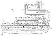
- FIG. 1is a schematic diagram, with a portion shown in cross-section, of an illustrative embodiment of a system for treating a wound on a patient that includes a positive-pressure wound interface configured to produce reduced pressure at the wound by a Venturi effect;
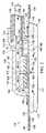
- FIG. 2is a schematic, cross-sectional view of an illustrative embodiment of the positive-pressure wound interface shown in FIG. 1 ;
- FIG. 3is a schematic, perspective view of an illustrative embodiment of a portion of a system for treating a wound on a patient that includes a positive-pressure wound interface and a Coanda device;
- FIG. 4is a schematic, perspective view of an illustrative embodiment of a Coanda device
- FIG. 5is a schematic, perspective view, of a portion of the Coanda device of FIG. 4 shown over a wound;
- FIG. 6is a schematic, cross-sectional view of an illustrative embodiment of a wound interface for use in a system for treating a wound on a patient that utilizes a Venturi effect to deliver a reduced pressure to the wound.
- the tissue sitemay be, for example, a wound 102 on a patient 104 .
- the system 100may include a positive-pressure wound interface 106 that has an interface body 108 .
- the interface body 108may include a positive-pressure channel 110 and a reduced-pressure channel 112 .
- the positive-pressure channel 110may be configured to create a Venturi effect as positive pressure flows through the positive-pressure channel 110 and past the reduced-pressure channel 112 . In this manner, the interface body 108 may enable the delivery of reduced pressure to the wound 102 as the positive pressure flows through the positive-pressure channel 110 and past the reduced-pressure channel 112 .
- the system 100may further include a wound dressing 114 positioned adjacent the wound 102 .
- the system 100may work with many types of dressings, but is shown in FIG. 1 , for example, with the wound dressing 114 .
- the wound dressing 114includes a wound filler 113 that may be comprised of a wound-interface layer 116 and an absorbent layer 118 .
- the wound filler 113has a first side 115 and a second, tissue-facing side 117 .
- the wound-interface layer 116may be a manifold, wicking layer, or other material for interfacing with the wound 102 .
- a manifoldrefers generally to a substance or structure that is provided to assist in applying reduced pressure to, delivering fluids to, or removing fluids from a tissue site, such as the wound 102 .
- the manifoldincludes a plurality of flow channels or pathways that distribute fluids provided to and removed from the wound 102 around the manifold.
- the flow channels or pathwaysare interconnected to improve distribution of fluids provided to or removed from the wound 102 .
- the manifoldmay be a biocompatible material that is capable of being placed in contact with the wound 102 and distributing reduced pressure to the wound 102 .
- manifoldsinclude, without limitation, one or more of the following: devices that have structural elements arranged to form flow channels, such as, for example, cellular foam, open-cell foam, porous tissue collections, liquids, gels, and foams that include, or cure to include, flow channels; porous material, such as foam, gauze, felted mat, or similar material suited to a particular biological application; porous foam that includes a plurality of interconnected cells or pores that act as flow channels, such as, for example, a polyurethane, open-cell, reticulated foam such as GranuFoam® material manufactured by Kinetic Concepts, Incorporated of San Antonio, Tex.; a bioresorbable material; or a scaffold material.
- devices that have structural elements arranged to form flow channelssuch as, for example, cellular foam, open-cell foam, porous tissue collections, liquids, gels, and foams that include, or cure to include, flow channels
- porous materialsuch as foam, gauze, felted mat, or similar material suited to
- the absorbent layer 118may absorb liquid from the wound 102 .
- the absorbent layer 118may be any material that retains liquids and may comprise one or more of the following: Luquafleece® material, BASF 402c, Technical Absorbents 2317 available from Technical Absorbents (www.techabsorbents.com), sodium polyacrylate super absorbers, cellulosics (carboxy methyl cellulose and salts such as sodium CMC), or alginates.
- the absorbent layer 118may allow fluids and exudate removed from the wound 102 to be stored within the wound filler 113 instead of storing the wound fluids remotely in a canister.
- the wound dressing 114may be configured to encourage the evaporation of moisture stored within the wound filler 113 to keep the wound filler 113 from becoming overly saturated with wound fluid. If the wound filler 113 becomes overly saturated with fluid, the wound filler 113 may not be able to absorb additional fluids from the wound 102 .
- the wound dressing 114may further include a sealing member 120 disposed over the wound filler 113 and a portion of intact skin 122 to form a sealed space 124 .
- the sealing member 120may include a first side 130 and a second, tissue facing side 132 .
- a treatment aperture 126may be formed in the sealing member 120 to provide fluid access to the sealed space 124 .
- the positive-pressure wound interface 106may be in fluid communication with the treatment aperture 126 .
- the sealing member 120may be any liquid-impervious material capable of forming the sealed space 124 into which reduced pressure may be applied.
- the sealing member 120may be formed from a high-moisture-vapor-transfer-rate material (high MVTR material) or a drape material that may be a flexible film.
- “Moisture Vapor Transmission Rate” or “MVTR”represents the amount of moisture that can pass through a material in a given period of time.
- a high-moisture-vapor-transfer-rate materialtypically has a moisture vapor transmission rate greater than 300 g/m 2 per 24 hours, and more typically 1000 g/m 2 per 24 hours or more
- the sealing member 120allows vapor to egress from the sealed space 124 through the sealing member 120 to the atmosphere exterior to the wound dressing 114 .
- the sealing member 120may comprise one or more of the following: hydrophilic polyurethane; cellulosics; hydrophilic polyamides; an INSPIRE 2301 material from Expopack Advanced Coatings of Wrexham, United Kingdom; a thin, uncoated polymer drape; natural rubbers; polyisoprene; styrene butadiene rubber; chloroprene rubber; polybutadiene; nitrile rubber; butyl rubber; ethylene propylene rubber; ethylene propylene diene monomer; chlorosulfonated polyethylene; polysulfide rubber; polyurethane (PU); EVA film; co-polyester; silicones; silicone drape; a 3M Tegaderm® drape; a polyurethane (PU) drape, such as one available from Avery Dennison Corporation of Pasadena, Calif.; polyether block polyamide copolymer (PEBAX), for example, from Arkema, France; or other similar material.
- hydrophilic polyurethane
- An attachment device 128may be coupled to all or a portion of a second, patient-facing side 132 of the sealing member 120 .
- the attachment device 128may attach the sealing member 120 to the portion of intact skin 122 of the patient 104 and/or a portion of the wound filler 113 .
- the performance of the sealing member 120 with respect to MVTRmay be enhanced by only covering a limited surface area of the second, patient-facing side 132 of the sealing member 120 with the attachment device 128 .
- a limited patternmay be used.
- only 30 to 60 percent of the surface area of the second, patient-facing side 132may be covered with the attachment device 128 .
- the attachment device 128may be applied on the second, patient-facing side 132 in a limited pattern, such as, for example, a grid, spaced dots, swirls, or other patterns.
- the positive pressure wound interface 106may be coupled to the first side 130 of the sealing member 120 by any of the previously mentioned coupling techniques, or other similar techniques.
- the system 100may further include a positive-pressure source 134 fluidly coupled to the positive-pressure wound interface 106 such that the positive-pressure wound interface 106 may receive positive pressure from the positive-pressure source 134 .
- a positive-pressure conduit 136may couple the positive-pressure source 134 to the positive-pressure wound interface 106 .
- the positive-pressure conduit 136may be coupled by bonding, tube locks, interference fit, or other technique to the positive-pressure wound interface 106 .
- FIG. 1illustrates the positive-pressure conduit 136 coupling the positive-pressure wound interface 106 to the positive-pressure source 134
- the positive-pressure source 134may be an integral part of the wound dressing 114 .
- the positive-pressure conduit 136may be optional.
- the positive-pressure source 134may be any device for supplying positive pressure, such as, for example, a positive-pressure pump.
- the positive-pressure source 134may be a diaphragm pump or a disc-pump.
- a disc-pumpmay be positioned adjacent or within the wound dressing 114 .
- the disc-pumpmay be an integral part of the wound dressing 114 .
- the positive-pressure source 134may be capable of delivering a flow rate between about 0.1 L/Min. to about 4 L/min. In a specific, non-limiting embodiment, the positive-pressure source 134 may be capable of providing a flow rate of about 3 L/min when the positive-pressure source 134 is not connected to the positive-pressure wound interface 106 , and a flow rate of about 1 L/Min. to about 1.5 L/min at 50 mm Hg when the positive-pressure source 134 is connected to the positive-pressure wound interface 106 . In the above embodiments, the flow rate provides a fluid speed necessary to obtain the desired reduced pressure using the Venturi effect.
- the amount and nature of the positive pressure supplied to the positive-pressure wound interface 106may vary depending on the construction of the positive-pressure wound interface 106 and the desired amount or nature of the reduced pressure being supplied to the wound 102 .
- the desired reduced pressure supplied to the wound 102may be between about ⁇ 5 mm Hg ( ⁇ 667 Pa) to about ⁇ 500 mm Hg ( ⁇ 66.7 kPa), and more specifically between about ⁇ 75 mm Hg ( ⁇ 9.9 kPa) to about ⁇ 300 mm Hg ( ⁇ 39.9 kPa).
- the positive pressuremay be supplied continuously or intermittently, causing the reduced pressure to be applied to the wound 102 either continuously or intermittently.
- the positive-pressure source 134may be housed within or used in conjunction with a pressure sensing unit 138 .
- the positive-pressure source 134 and the pressure sensing unit 138may comprise a therapy unit.
- the pressure sensing unit 138may contain sensors, processing units, alarm indicators, memory, databases, software, display units, and user interfaces that further facilitate the application of reduced pressure treatment to the wound 102 .
- pressure-detection sensors(not shown) located in the pressure sensing unit 138 may receive pressure data from the positive-pressure wound interface 106 via one or more sensing lumens 140 .
- the sensing lumens 140may be dedicated to delivering reduced pressure data to the pressure-detection sensors.
- the pressure-detection sensorsmay communicate with a processing unit, or controller 142 .
- the controller 142may monitor and control the reduced pressure delivered to the wound 102 by controlling, for example, the flow rate from the positive pressure source 134 .
- the positive-pressure wound interface 106has a first side 144 and a second, tissue-facing side 146 .
- the second, tissue-facing side 146 of the positive-pressure wound interface 106may be disposed on the sealing member 120 proximate the treatment aperture 126 .
- the positive-pressure wound interface 106may be comprised of the interface body 108 .
- the interface body 108has a first side 148 and a second, tissue-facing side 150 .
- the positive pressure wound interface 106may be a single, molded piece made from flexible, stable polymers such as silicones, polyurethane (PU), rubber, or similar materials.
- the positive-pressure wound interface 106may be assembled from two parts, each part being a different material.
- An inner partmay be comprised of a rigid polymer such as an acrylonitrile butadiene styrene (ABS) or a polycarbonate acrylonitrile butadiene styrene(PC/ABS).
- An outer partmay be positioned around a portion of the inner part.
- the outer partmay be comprised of one of the flexible polymers described above, such as silicones, PU, or rubber.
- the positive-pressure wound interface 106may be assembled from two parts as described above to help the positive-pressure wound interface 106 from deforming under thermal and pressure changes. Portions of the positive-pressure wound interface 106 subject to air flow may have surfaces that are smooth and substantially free of molding inclusions to avoid air turbulences.
- An inlet 152may be formed within the interface body 108 .
- the inlet 152may include a positive-pressure port 154 and a reduced-pressure-sensing port 156 that are fluidly isolated from each other at least proximate the inlet 152 .
- the positive-pressure port 154may be in fluid communication with, or fluidly coupled to, the positive-pressure conduit 136 .
- the reduced-pressure-sensing port 156may be in fluid communication, with or fluidly coupled to, the one or more sensing lumens 140 by way of a reduced-pressure-sensing channel 157 .
- the positive-pressure channel 110extends through the interface body 108 from the positive-pressure port 154 to a positive-pressure outlet 160 .
- the positive-pressure channel 110may have a longitudinal axis substantially parallel to the surface of the wound 102 , or at an angle to the surface of the wound 102 , when positioned for use.
- the positive-pressure channel 110may be configured to deliver the positive pressure through the interface body 108 from the positive-pressure port 154 downstream to the positive-pressure outlet 160 .
- the positive-pressure channel 110may have a surface that is smooth and substantially free of molding inclusions to avoid air turbulences within the positive-pressure channel 110 .
- the positive-pressure channel 110may be in fluid communication with a plurality of positive-pressure outlets 160 for directing flow circumferentially about the interface body 108 and over the sealing member 120 , as described further below.
- the positive-pressure outlet 160may be a single outlet, such as a circumferential outlet, circumscribing the interface body 108 for providing circumferential flow.
- the positive-pressure channel 110may include at least one constricted portion 162 .
- the at least one constricted portion 162may have a slope of approximately 20, 25, 30, or 40 degrees (and any number of degrees thereinbetween) relative to the longitudinal axis of the positive-pressure channel 110 or the longitudinal axis of the constricted portion 162 .
- the slope of the at least one constricted portion 162may be gradual to avoid air turbulence within the positive-pressure channel 110 for a given set of operational parameters such as, for example, air flow velocity and pressures.
- the positive-pressure channel 110may be configured to create a Venturi effect when experiencing sufficient fluid flow therethrough.
- the Venturi effectis a jet effect that results in a reduction in pressure when the velocity of an air flow increases due to the principles of continuity.
- a high flow fluidfor example air
- the velocity of the airincreases.
- the positive-pressure wound interface 106 as a whole, including the positive-pressure channel 110is configured to take advantage of the Venturi effect to create a reduced pressure that may be applied to the wound 102 via the reduced-pressure channel 112 .
- the at least one constricted portion 162 of the positive-pressure channel 110may be cone shaped with a first end 174 having a first diameter, D 1 , and a second, opposing end 176 having a second diameter, D 2 , such that the first diameter, D 1 , is larger than the second diameter, D 2 .
- the first diameter, D 1may be between about 5 millimeters to about 10 millimeters (mm)
- the second diameter, D 2may be between about 0.2 mm to about 0.7 mm.
- the at least one constricted portion 162may be formed in any suitable shape capable of inducing the Venturi effect and minimizing air turbulence within the positive-pressure wound interface 106 , as described above.
- Bernoulli's equationmay be used to optimize the construction of the positive-pressure wound interface 106 .
- Bernoulli's equationmay be used to calculate the pressure drop for a given construction of the positive-pressure wound interface 106 .
- the pressure dropmay correspond to the amount of reduced pressure applied to the wound 102 .
- the reduced-pressure channel 112may be fluidly coupled to the positive-pressure channel 110 such that the reduced-pressure channel 112 is in fluid communication with the positive-pressure channel 110 .
- the reduced-pressure channel 112may include a first end 158 fluidly coupled to the positive-pressure channel 110 and a second, tissue-facing end 164 fluidly coupled to a tissue inlet 166 .
- the tissue inlet 166may be proximate the second, tissue-facing side 150 of the interface body 108 .
- the reduced-pressure channel 112may extend from the positive-pressure channel 110 to the tissue-facing side 150 of the interface body 108 .
- the reduced-pressure channel 112may be coupled to the positive-pressure channel 110 downstream of the at least one constricted portion 162 .
- the reduced-pressure channel 112may be coupled to the positive-pressure channel 110 at the at least one constricted portion 162 .
- the longitudinal dimension of the reduced-pressure channel 112which extends from the positive-pressure channel 110 to the tissue-facing side 150 of the interface body 108 , may be greater than about 15 millimeters (mm). In other non-limiting embodiments, the longitudinal dimension may be between about 5 mm to about 20 mm.
- the reduced-pressure channel 112may be substantially perpendicular to the longitudinal axis of the positive-pressure channel 110 .
- the reduced-pressure channel 112may be configured to deliver reduced pressure to the wound 102 when positive pressure is pushed into the positive-pressure channel 110 and past the reduced-pressure channel 112 at an adequate speed.
- the reduced-pressure channel 112may have a surface that is smooth and substantially free of molding inclusions to avoid air turbulences within the positive-pressure wound interface 106 .
- the positive-pressure wound interface 106may be configured so that air flowing through the positive-pressure channel 110 entrains air, including air from the reduced-pressure channel 112 , that is then vented through the positive-pressure outlet 160 .
- the positive-pressure outlet 160may be configured to direct air flow circumferentially over the first side 130 of the sealing member 120 to enhance the moisture-vapor-transmission rate of the sealing member 120 . As previously mentioned, enhancing the moisture-vapor-transmission rate may increase the life of the wound filler 113 by keeping the wound filler 113 from becoming saturated with wound fluid.
- the positive-pressure outlet 160may be configured to vent directly to the atmosphere.
- one or more ducts 168see FIGS.
- the one or more ducts 168may include or be attached to a Coanda device as will be described in more detail below with reference to FIGS. 3-5 .
- the wound dressing 114may further comprise a hydrophobic filter 170 positioned adjacent the tissue inlet 166 for preventing wound exudate from entering the reduced-pressure channel 112 .
- the hydrophobic filter 170may be fluidly coupled anywhere in the reduced-pressure channel 112 .
- a regulating valve 172may be associated with the reduced pressure channel 112 for regulating the amount of reduced pressure being supplied to the wound 102 independently of the air speed in the positive-pressure chamber 110 .
- the regulating valve 172may provide pressure regulation at the wound 102 that is independent of the pressure in the positive-pressure channel 110 .
- the controller 142may be used to vary the amount of positive pressure provided by, for example, the positive pressure source 134 , to control the amount of reduced pressure applied at the wound 102 .
- the controller 142may receive feedback from the pressure sensing unit 138 that indicates the amount of pressure being applied to the wound 102 . Based on the feedback, the controller 142 may signal the positive-pressure source 134 to vary or modulate the amount of positive pressure generated by the positive-pressure source 134 so that the reduced pressure applied to the wound 102 reaches a desired level.
- Power provided to the positive-pressure source 134may be varied or modulated to vary the amount of positive pressure generated by the positive pressure source 134 .
- a control valve(not shown) may also be utilized to vary the amount of positive pressure.
- the controller 142may allow the system 100 to operate over a range of desired reduced pressure levels.
- the controller 142may be configured to operate at a number of preset reduced pressure levels that may be selected by or provided to a healthcare provider.
- the controller 142may improve the efficiency of the positive-pressure source 134 by modulating power to the positive pressure source 134 based on the desired amount of positive pressure to be generated. In the instance that a battery is used to power the positive-pressure source 134 , the battery life may be extended in this manner.
- the controller 142may be coupled to an atmospheric pressure sensor (not shown).
- the atmospheric pressuremay vary depending on various elements, including the altitude in which the system 100 is operating. The effects of variable atmospheric pressure may affect the performance of the system 100 .
- the atmospheric pressure sensormay allow the controller 142 to account for variances in the atmospheric pressure and signal or command the positive-pressure source 134 accordingly. In other words, the controller 142 may signal the positive-pressure source 134 to increase or decrease the pressure output based on variances in atmospheric pressure.
- the system 100 illustrated in FIG. 1may further include a Coanda device 210 associated with the positive-pressure wound interface 106 .
- the Coanda device 210may receive fluid exiting the positive-pressure wound interface 106 to encourage airflow over the wound dressing 114 for enhancing evaporation of liquids from the wound dressing 114 .
- enhanced evaporation of liquids from the wound dressing 114may allow the wound dressing 114 to process relatively more fluids.
- the positive-pressure wound interface 106 and the Coanda device 210may be associated with one another in several ways.
- the positive-pressure wound interface 106may be coupled to the Coanda device 210 , formed integrally with the Coanda device 210 , or placed adjacent to the Coanda device 210 .
- the Coanda device 210may be coupled to the positive pressure outlet 160 of the positive-pressure wound interface 106 by the one or more ducts 168 .
- other entrainment devicesmay be used as the Coanda device 210 to entrain air and direct the air over the wound dressing 114 to achieve the desired air-flow.
- These other entrainment devicessuch as, for example, a Conventional Ejector, may be used to entrain air to create a more voluminous flow based on the presence of a high pressure flow.
- the Conventional Ejectormay utilize a primary flow located proximate to an available secondary air source that is “dragged” by an airfoil shape to have the effect of an air-multiplier.
- the Coanda device 210may be a device for entraining air, as described above, that utilizes the Coanda effect.
- the Coanda effectis generally a phenomena in which a flow attaches itself to a nearby surface and remains attached even as the surface (Coanda surface) pulls away from the initial direction of the flow. As the flow curves away, the flow may entrain surrounding fluids and increase the volume of the flow. The Coanda surface close to the flow may restrict the entrainment in that region, and as the flow accelerates to try to balance a momentum transfer, a pressure differential may develop across the flow that changes or deflects the direction of the flow closer to the surface.
- the Coanda effectis named for Henri Coanda and the concept is described in U.S. Pat. No. 2,052,869, granted to Coanda.
- the Coanda device 210creates a desired airflow as suggested by arrows 240 .
- the Coanda device 210may be fluidly coupled by the one or more ducts 168 to the positive-pressure outlet 160 formed in the positive-pressure wound interface 106 .
- the positive-pressure outlet 160may supply a relatively high pressure air to the Coanda device 210 .
- the discharge flow rate exiting the positive-pressure outlet 160may be approximately 2 L/min or greater.
- airis intended to cover other working gases that may be used to help remove moisture.
- the Coanda device 210may receive positive pressure air from the one or more ducts 168 and develop an enhanced air flow that is delivered from the Coanda device 210 over the first side 130 of the sealing member 120 . As the air moves across the wound dressing 114 , any moisture or vapor on the first side 130 of the sealing member 120 may be removed. This may increase or maintain a strong relative humidity gradient across the sealing member 120 that helps remove liquid from the wound dressing 114 , which may enhance the ability of the wound dressing 114 to process liquids.
- the Coanda device 210may include an annular nozzle 246 .
- the annular nozzle 246may form a central opening 248 .
- the central opening 248may surround much of the interface body 108 and a portion of the interface body 108 may extend through the central opening 248 .
- the annular nozzle 246may have walls 250 that form an interior passage 252 .
- a nozzle opening 254may be formed on the annular nozzle 246 on a portion in or near the central opening 248 .
- a portion of the walls 250may form a Coanda surface 256 proximate to and downstream from the nozzle opening 254 .
- the fluid or air exiting the nozzle opening 254may entrain additional fluid from the central opening 248 as the air flow follows the Coanda surface 256 .
- the flow of air from the nozzle opening 254 plus the entrained air from the central opening 248may produce a combined fluid flow.
- airmay be moved out of the nozzle opening 254 as suggested by arrows 258 .
- the airflowmay entrain additional air from the central opening 248 as suggested by arrows 260 .
- the combined fluid flowis suggested by the arrows 240 .
- the Coanda device 210may operate as described in various positions, and thus, the positioning depicted in FIGS. 3-5 may be may be flipped or rotated for orienting the nozzle opening 254 to discharge air away from a base portion of the interface body 108 such that air recruited from the central opening 248 is pulled from proximate the first side 130 of the sealing member 120 .
- a number of devices or elementsmay be used to position the Coanda device 210 to have a flow clearance 268 between the Coanda device 210 and the sealing member 120 .
- a plurality of rib members 270may be used to suspend the annular nozzle 246 of the Coanda device 210 to create the flow clearance 268 .
- the reduced-pressure sourcemay be analogous to the positive-pressure source 134 , but adapted to provide reduced-pressure.
- the reduced-pressure wound interface 306 and the reduced-pressure sourcemay be part of a reduced-pressure treatment system used to treat a wound with reduced pressure.
- the reduced-pressure wound interface 306may be analogous in many respects to the positive-pressure wound interface 106 illustrated in FIG. 1 . Namely, the reduced-pressure wound interface 306 may be configured to create a Venturi effect that develops the reduced pressure at a wound.
- the reduced-pressure wound interface 306may have an interface body 308 that may include a first reduced-pressure channel 310 and a second reduced-pressure channel 312 .
- the first reduced-pressure channel 310may be configured to create a Venturi effect as air is pulled through the first reduced-pressure channel 310 and past the second reduced-pressure channel 312 .
- Airmay be pulled through the first reduced-pressure channel 310 by the reduced-pressure source.
- the interface body 308may enable the delivery of reduced pressure to the wound as the air flows through the first reduced-pressure channel 310 and past the second reduced-pressure channel 312 .
- a wound dressing 314may be positioned adjacent the wound. Similar to the wound dressing 114 , the wound dressing 314 may include a wound filler 313 that may be comprised of a wound-interface layer and an absorbent layer (not shown).
- the wound-interface layermay be a manifold as described above.
- the wound filler 313may be a manifold only since liquids may be removed directly as described herein.
- the wound filler 313may be covered by a sealing member 320 .
- the sealing member 320may be formed from a high-moisture-vapor-transfer-rate material (high MVTR material) or a drape material that may be a flexible film.
- the amount, nature, or pressure of the air pulled through the first reduced-pressure channel 310may vary depending on the construction of the reduced-pressure wound interface 306 , ambient conditions, and the desired amount of the reduced pressure being supplied to the wound.
- the desired reduced pressure supplied to the woundmay be between about ⁇ 5 mm Hg ( ⁇ 667 Pa) to about ⁇ 500 mm Hg ( ⁇ 66.7 kPa), and more specifically between about ⁇ 75 mm Hg ( ⁇ 9.9 kPa) to about ⁇ 300 mm Hg ( ⁇ 39.9 kPa).
- the reduced-pressure sourcemay cause air to be pulled through the first reduced-pressure channel 310 either continuously or intermittently, causing the reduced pressure to be applied to the wound either continuously or intermittently.
- the reduced-pressure sourcemay be housed with or used in conjunction with a pressure-sensing unit (not explicitly shown but analogous to the pressure sensing unit 138 in FIG. 1 ).
- the pressure-sensing unitmay be fluidly coupled to a pressure-sensing port 356 formed in the interface body 308 such that the pressure-sensing port 356 has an opening adjacent a tissue-facing side of the interface body 308 .
- the pressure-sensing unitmay receive a pressure sample from the pressure-sensing port 356 for monitoring pressure at the wound.
- a controllermay be connected to the sensing unit and the reduced-pressure source. The controller may send signals or commands to the reduced-pressure source based on data received from the sensing unit to regulate the amount of reduced pressure supplied to the wound.
- An inlet port 352may be formed within the interface body 308 .
- the inlet port 352may allow the intake of an ambient gas.
- the inlet port 352may be shaped such that the inlet port 352 has a first diameter, D 1 , at an upstream end, and a second diameter, D 2 , at an opposing, downstream end.
- the first diameter, D 1may be larger than the second diameter, D 2 .
- the inlet port 352may have a constricted portion defined by the first and the second diameters, D 1 and D 2 .
- the inlet port 352may have a slope of approximately 20, 25, 30, 35, or 40 degrees (and any number of degrees thereinbetween) relative to a longitudinal axis of the first reduced-pressure channel 310 or the longitudinal axis of the constricted portion.
- the first reduced-pressure channel 310may extend through the interface body 308 from the inlet port 352 to an outlet port 360 .
- the first reduced-pressure channel 310may have a longitudinal axis that is substantially parallel to the surface of the wound, or at an angle to the surface of the wound, when positioned for use.
- the first reduced-pressure channel 310may be configured to pull air through the interface body 308 from the inlet port 352 downstream to the outlet port 360 .
- the first reduced-pressure channel 310may have a surface that is smooth and substantially free of molding inclusions to avoid air turbulences within the first reduced-pressure channel 310 .
- the second reduced-pressure channel 312may be coupled to the first reduced-pressure channel 310 such that the second reduced-pressure channel 312 is in fluid communication with the first reduced-pressure channel 310 .
- the second reduced-pressure channel 312may extend from the first reduced-pressure channel 310 to the tissue-facing side of the reduced-pressure wound interface 306 .
- the second reduced-pressure channel 312may be configured to deliver reduced pressure to the wound when a fluid or air is pulled through the inlet port 352 with sufficient flow rate to produce the reduced pressure at the wound by way of the Venturi effect.
- the second reduced-pressure channel 312may be coupled to the first reduced-pressure channel 310 downstream of the constricted portion.
- the second reduced-pressure channel 312may be coupled to the first reduced-pressure channel 310 at the constricted portion.
- the longitudinal dimension of the second reduced-pressure channel 312which extends from the first reduced-pressure channel 310 to the tissue-facing side of the interface body 308 , may be greater than 15 millimeters (mm). In other non-limiting embodiments, the longitudinal dimension may be between about 5 mm to about 20 mm.
- the second reduced-pressure channel 312may be substantially perpendicular to, or at an angle to, the longitudinal axis of the first reduced-pressure channel 310 .
- the second reduced-pressure channel 312may have a surface that is smooth and substantially free of molding inclusions to avoid air turbulences within the interface 306 .
- the reduced-pressure wound interface 306may be configured so that air pulled into the first reduced-pressure channel 310 via the inlet port 352 entrains air surrounding the sealing member 320 .
- the air flow caused by the air being pulled into the inlet port 352may cause air to flow over the sealing member 320 to enhance the moisture-vapor-transmission rate of the sealing member 320 .
- enhancing the moisture-vapor-transmission ratemay increase the life of the wound filler 313 by keeping the wound filler 313 from becoming overly saturated with wound fluid.
- the wound dressing 314may further comprise a hydrophobic filter 370 positioned between the wound and the first reduced-pressure channel 310 .
- the hydrophobic filter 370may be positioned within the second reduced-pressure channel 312 .
- no hydrophobic filtermay be used and wound exudate removed from the wound may be pulled through the first and second reduced-pressure channels 310 , 312 and deposited in a canister (not shown).
- a regulating valve 372may be associated with the second reduced-pressure channel 312 for regulating the amount of reduced pressure being supplied to the wound.
- the regulating valve 372may provide pressure regulation at the wound that is independent of the reduced pressure in the first reduced-pressure channel 310 .
Landscapes
- Health & Medical Sciences (AREA)
- Heart & Thoracic Surgery (AREA)
- Vascular Medicine (AREA)
- Engineering & Computer Science (AREA)
- Anesthesiology (AREA)
- Biomedical Technology (AREA)
- Hematology (AREA)
- Life Sciences & Earth Sciences (AREA)
- Animal Behavior & Ethology (AREA)
- General Health & Medical Sciences (AREA)
- Public Health (AREA)
- Veterinary Medicine (AREA)
- Media Introduction/Drainage Providing Device (AREA)
- External Artificial Organs (AREA)
- Surgical Instruments (AREA)
Abstract
Description
Claims (24)
Priority Applications (3)
| Application Number | Priority Date | Filing Date | Title |
|---|---|---|---|
| US13/955,662US9623159B2 (en) | 2012-08-03 | 2013-07-31 | Interfaces, systems, and methods for use in reduced pressure tissue treatment |
| US15/453,510US10335522B2 (en) | 2012-08-03 | 2017-03-08 | Interfaces, systems, and methods for use in reduced pressure tissue treatment |
| US16/419,829US20190269836A1 (en) | 2012-08-03 | 2019-05-22 | Interfaces, systems, and methods for use in reduced pressure tissue treatment |
Applications Claiming Priority (2)
| Application Number | Priority Date | Filing Date | Title |
|---|---|---|---|
| US201261679282P | 2012-08-03 | 2012-08-03 | |
| US13/955,662US9623159B2 (en) | 2012-08-03 | 2013-07-31 | Interfaces, systems, and methods for use in reduced pressure tissue treatment |
Related Child Applications (1)
| Application Number | Title | Priority Date | Filing Date |
|---|---|---|---|
| US15/453,510DivisionUS10335522B2 (en) | 2012-08-03 | 2017-03-08 | Interfaces, systems, and methods for use in reduced pressure tissue treatment |
Publications (2)
| Publication Number | Publication Date |
|---|---|
| US20140039424A1 US20140039424A1 (en) | 2014-02-06 |
| US9623159B2true US9623159B2 (en) | 2017-04-18 |
Family
ID=48980332
Family Applications (3)
| Application Number | Title | Priority Date | Filing Date |
|---|---|---|---|
| US13/955,662Expired - Fee RelatedUS9623159B2 (en) | 2012-08-03 | 2013-07-31 | Interfaces, systems, and methods for use in reduced pressure tissue treatment |
| US15/453,510Expired - Fee RelatedUS10335522B2 (en) | 2012-08-03 | 2017-03-08 | Interfaces, systems, and methods for use in reduced pressure tissue treatment |
| US16/419,829AbandonedUS20190269836A1 (en) | 2012-08-03 | 2019-05-22 | Interfaces, systems, and methods for use in reduced pressure tissue treatment |
Family Applications After (2)
| Application Number | Title | Priority Date | Filing Date |
|---|---|---|---|
| US15/453,510Expired - Fee RelatedUS10335522B2 (en) | 2012-08-03 | 2017-03-08 | Interfaces, systems, and methods for use in reduced pressure tissue treatment |
| US16/419,829AbandonedUS20190269836A1 (en) | 2012-08-03 | 2019-05-22 | Interfaces, systems, and methods for use in reduced pressure tissue treatment |
Country Status (3)
| Country | Link |
|---|---|
| US (3) | US9623159B2 (en) |
| EP (1) | EP2879732B1 (en) |
| WO (1) | WO2014022548A1 (en) |
Cited By (33)
| Publication number | Priority date | Publication date | Assignee | Title |
|---|---|---|---|---|
| US20210228795A1 (en)* | 2018-05-01 | 2021-07-29 | Purewick Corporation | Fluid collection devices, related systems, and related methods |
| US11925575B2 (en) | 2021-02-26 | 2024-03-12 | Purewick Corporation | Fluid collection devices having a sump between a tube opening and a barrier, and related systems and methods |
| US11938053B2 (en) | 2018-05-01 | 2024-03-26 | Purewick Corporation | Fluid collection devices, systems, and methods |
| US12029678B2 (en) | 2016-07-27 | 2024-07-09 | Purewick Corporation | Male urine collection device using wicking material |
| US12029677B2 (en) | 2021-04-06 | 2024-07-09 | Purewick Corporation | Fluid collection devices having a collection bag, and related systems and methods |
| US12042423B2 (en) | 2020-10-07 | 2024-07-23 | Purewick Corporation | Fluid collection systems including at least one tensioning element |
| US12048644B2 (en) | 2020-11-03 | 2024-07-30 | Purewick Corporation | Apparatus for receiving discharged urine |
| US12048643B2 (en) | 2020-05-27 | 2024-07-30 | Purewick Corporation | Fluid collection assemblies including at least one inflation device and methods and systems of using the same |
| US12070432B2 (en) | 2020-11-11 | 2024-08-27 | Purewick Corporation | Urine collection system including a flow meter and related methods |
| US12121468B2 (en) | 2014-03-19 | 2024-10-22 | Purewick Corporation | Apparatus and methods for receiving discharged urine |
| US12138195B2 (en) | 2020-04-10 | 2024-11-12 | Purewick Corporation | Fluid collection assemblies including one or more leak prevention features |
| US12138196B2 (en) | 2014-03-19 | 2024-11-12 | Purewick Corporation | Apparatus and methods for receiving discharged urine |
| US12150885B2 (en) | 2021-05-26 | 2024-11-26 | Purewick Corporation | Fluid collection system including a cleaning system and methods |
| US12156792B2 (en) | 2020-09-10 | 2024-12-03 | Purewick Corporation | Fluid collection assemblies including at least one inflation device |
| US12161579B2 (en) | 2014-03-19 | 2024-12-10 | Purewick Corporation | Apparatus and methods for receiving discharged urine |
| US12178735B2 (en) | 2021-02-09 | 2024-12-31 | Purewick Corporation | Noise reduction for a urine suction system |
| US12186229B2 (en) | 2021-01-19 | 2025-01-07 | Purewick Corporation | Variable fit fluid collection devices, systems, and methods |
| US12193962B2 (en) | 2016-06-02 | 2025-01-14 | Purewick Corporation | Using wicking material to collect liquid for transport |
| US12208031B2 (en) | 2020-10-21 | 2025-01-28 | Purewick Corporation | Adapters for fluid collection devices |
| US12233003B2 (en) | 2021-04-29 | 2025-02-25 | Purewick Corporation | Fluid collection assemblies including at least one length adjusting feature |
| US12245967B2 (en) | 2020-11-18 | 2025-03-11 | Purewick Corporation | Fluid collection assemblies including an adjustable spine |
| US12251333B2 (en) | 2021-05-21 | 2025-03-18 | Purewick Corporation | Fluid collection assemblies including at least one inflation device and methods and systems of using the same |
| US12257173B2 (en) | 2017-01-31 | 2025-03-25 | Purewick Corporation | Apparatus and methods for receiving discharged urine |
| US12257174B2 (en) | 2020-10-21 | 2025-03-25 | Purewick Corporation | Fluid collection assemblies including at least one of a protrusion or at least one expandable material |
| US12268627B2 (en) | 2021-01-06 | 2025-04-08 | Purewick Corporation | Fluid collection assemblies including at least one securement body |
| US12274638B2 (en) | 2018-05-01 | 2025-04-15 | Purewick Corporation | Fluid collection devices, related systems, and related methods |
| US12295876B2 (en) | 2018-05-01 | 2025-05-13 | Purewick Corporation | Fluid collection devices and methods of using the same |
| US12324767B2 (en) | 2021-05-24 | 2025-06-10 | Purewick Corporation | Fluid collection assembly including a customizable external support and related methods |
| US12329364B2 (en) | 2019-07-19 | 2025-06-17 | Purewick Corporation | Fluid collection devices including at least one shape memory material |
| US12350190B2 (en) | 2020-01-03 | 2025-07-08 | Purewick Corporation | Urine collection devices having a relatively wide portion and an elongated portion and related methods |
| US12350187B2 (en) | 2020-08-11 | 2025-07-08 | Purewick Corporation | Fluid collection assemblies defining waist and leg openings |
| US12419778B2 (en) | 2019-06-21 | 2025-09-23 | Purewick Corporation | Fluid collection devices including a base securement area, and related systems and methods |
| US12440371B2 (en) | 2021-08-05 | 2025-10-14 | Purewick Corporation | Fluid collection system including a garment and a fluid collection device |
Families Citing this family (34)
| Publication number | Priority date | Publication date | Assignee | Title |
|---|---|---|---|---|
| GB2455962A (en) | 2007-12-24 | 2009-07-01 | Ethicon Inc | Reinforced adhesive backing sheet, for plaster |
| AU2009221772B2 (en) | 2008-03-05 | 2015-01-22 | Solventum Intellectual Properties Company | Dressing and method for applying reduced pressure to and collecting and storing fluid from a tissue site |
| US8814842B2 (en) | 2010-03-16 | 2014-08-26 | Kci Licensing, Inc. | Delivery-and-fluid-storage bridges for use with reduced-pressure systems |
| GB2488749A (en) | 2011-01-31 | 2012-09-12 | Systagenix Wound Man Ip Co Bv | Laminated silicone coated wound dressing |
| GB201106491D0 (en) | 2011-04-15 | 2011-06-01 | Systagenix Wound Man Ip Co Bv | Patterened silicone coating |
| US10940047B2 (en) | 2011-12-16 | 2021-03-09 | Kci Licensing, Inc. | Sealing systems and methods employing a hybrid switchable drape |
| CN103987348B (en) | 2011-12-16 | 2016-05-11 | 凯希特许有限公司 | Releasable Medical Drapes |
| AU2013344686B2 (en) | 2012-11-16 | 2018-06-21 | Solventum Intellectual Properties Company | Medical drape with pattern adhesive layers and method of manufacturing same |
| GB201222770D0 (en) | 2012-12-18 | 2013-01-30 | Systagenix Wound Man Ip Co Bv | Wound dressing with adhesive margin |
| EP3038667B1 (en) | 2013-08-26 | 2019-10-09 | KCI Licensing, Inc. | Dressing interface with moisture controlling feature and sealing function |
| US10946124B2 (en) | 2013-10-28 | 2021-03-16 | Kci Licensing, Inc. | Hybrid sealing tape |
| EP3527237B1 (en) | 2013-10-30 | 2020-09-09 | KCI Licensing, Inc. | Absorbent conduit and system |
| AU2014342903B2 (en) | 2013-10-30 | 2018-09-20 | Solventum Intellectual Properties Company | Dressing with differentially sized perforations |
| US9956120B2 (en) | 2013-10-30 | 2018-05-01 | Kci Licensing, Inc. | Dressing with sealing and retention interface |
| EP3062751B1 (en) | 2013-10-30 | 2017-08-09 | KCI Licensing, Inc. | Condensate absorbing and dissipating system |
| EP3110379B1 (en) | 2014-02-28 | 2019-04-03 | KCI Licensing, Inc. | Hybrid drape having a gel-coated perforated mesh |
| US11026844B2 (en) | 2014-03-03 | 2021-06-08 | Kci Licensing, Inc. | Low profile flexible pressure transmission conduit |
| WO2015168681A1 (en)* | 2014-05-02 | 2015-11-05 | Kci Licensing, Inc. | Fluid storage devices, systems, and methods |
| JP6640748B2 (en) | 2014-06-05 | 2020-02-05 | ケーシーアイ ライセンシング インコーポレイテッド | Dressing with fluid acquisition and dispensing features |
| WO2016100098A1 (en) | 2014-12-17 | 2016-06-23 | Kci Licensing, Inc. | Dressing with offloading capability |
| EP3574877B1 (en) | 2015-05-08 | 2022-08-17 | 3M Innovative Properties Company | Low-acuity dressing with integral pump |
| US10926007B2 (en)* | 2015-07-13 | 2021-02-23 | Conmed Corporation | Surgical suction device that uses positive pressure gas |
| EP3714916A1 (en) | 2015-07-29 | 2020-09-30 | Innovative Therapies Inc. | Wound therapy device pressure monitoring and control system |
| EP3741335B1 (en) | 2015-09-01 | 2023-05-24 | KCI Licensing, Inc. | Dressing with increased apposition force |
| EP3349807B1 (en) | 2015-09-17 | 2021-02-24 | 3M Innovative Properties Company | Hybrid silicone and acrylic adhesive cover for use with wound treatment |
| US20170172796A1 (en)* | 2015-12-16 | 2017-06-22 | Novartis Ag | Surgical system with substance delivery system |
| JP2019510554A (en)* | 2016-04-06 | 2019-04-18 | コンメッド コーポレイション | Surgical suction device using positive pressure gas |
| GB201811494D0 (en)* | 2018-07-13 | 2018-08-29 | Smith & Nephew | Inter-device communications and device control in wound therapy systems |
| US12263294B2 (en) | 2016-09-28 | 2025-04-01 | T.J.Smith And Nephew, Limited | Systems and methods for operating negative pressure wound therapy devices |
| CN108295321A (en)* | 2017-01-13 | 2018-07-20 | 厦门圣慈医疗器材有限公司 | sucker |
| WO2019084006A1 (en)* | 2017-10-23 | 2019-05-02 | Kci Licensing, Inc. | Low profile distribution components for wound therapy |
| US11554204B2 (en)* | 2018-01-15 | 2023-01-17 | Kci Licensing, Inc. | Systems and methods for controlling negative pressure therapy using properties of fluids from a tissue site |
| WO2020139541A1 (en)* | 2018-12-26 | 2020-07-02 | Kci Licensing, Inc. | Wound based sensor system with ambient atmosphere monitoring |
| EP4463194A1 (en)* | 2022-01-14 | 2024-11-20 | T.J. Smith and Nephew, Limited | Self-calibration with dynamic therapy performance for negative pressure wound therapy devices |
Citations (130)
| Publication number | Priority date | Publication date | Assignee | Title |
|---|---|---|---|---|
| US1355846A (en) | 1920-02-06 | 1920-10-19 | David A Rannells | Medical appliance |
| US2547758A (en) | 1949-01-05 | 1951-04-03 | Wilmer B Keeling | Instrument for treating the male urethra |
| US2632443A (en) | 1949-04-18 | 1953-03-24 | Eleanor P Lesher | Surgical dressing |
| GB692578A (en) | 1949-09-13 | 1953-06-10 | Minnesota Mining & Mfg | Improvements in or relating to drape sheets for surgical use |
| US2682873A (en) | 1952-07-30 | 1954-07-06 | Johnson & Johnson | General purpose protective dressing |
| US2910763A (en) | 1955-08-17 | 1959-11-03 | Du Pont | Felt-like products |
| US2969057A (en) | 1957-11-04 | 1961-01-24 | Brady Co W H | Nematodic swab |
| US3066672A (en) | 1960-09-27 | 1962-12-04 | Jr William H Crosby | Method and apparatus for serial sampling of intestinal juice |
| US3367332A (en) | 1965-08-27 | 1968-02-06 | Gen Electric | Product and process for establishing a sterile area of skin |
| US3520300A (en) | 1967-03-15 | 1970-07-14 | Amp Inc | Surgical sponge and suction device |
| US3568675A (en) | 1968-08-30 | 1971-03-09 | Clyde B Harvey | Fistula and penetrating wound dressing |
| US3648692A (en) | 1970-12-07 | 1972-03-14 | Parke Davis & Co | Medical-surgical dressing for burns and the like |
| US3682180A (en) | 1970-06-08 | 1972-08-08 | Coilform Co Inc | Drain clip for surgical drain |
| US3826254A (en) | 1973-02-26 | 1974-07-30 | Verco Ind | Needle or catheter retaining appliance |
| DE2640413A1 (en) | 1976-09-08 | 1978-03-09 | Wolf Gmbh Richard | CATHETER MONITORING DEVICE |
| US4080970A (en) | 1976-11-17 | 1978-03-28 | Miller Thomas J | Post-operative combination dressing and internal drain tube with external shield and tube connector |
| US4096853A (en) | 1975-06-21 | 1978-06-27 | Hoechst Aktiengesellschaft | Device for the introduction of contrast medium into an anus praeter |
| US4139004A (en) | 1977-02-17 | 1979-02-13 | Gonzalez Jr Harry | Bandage apparatus for treating burns |
| US4165748A (en) | 1977-11-07 | 1979-08-28 | Johnson Melissa C | Catheter tube holder |
| US4184510A (en) | 1977-03-15 | 1980-01-22 | Fibra-Sonics, Inc. | Valued device for controlling vacuum in surgery |
| WO1980002182A1 (en) | 1979-04-06 | 1980-10-16 | J Moss | Portable suction device for collecting fluids from a closed wound |
| US4233969A (en) | 1976-11-11 | 1980-11-18 | Lock Peter M | Wound dressing materials |
| US4245630A (en) | 1976-10-08 | 1981-01-20 | T. J. Smith & Nephew, Ltd. | Tearable composite strip of materials |
| US4256109A (en) | 1978-07-10 | 1981-03-17 | Nichols Robert L | Shut off valve for medical suction apparatus |
| US4261363A (en) | 1979-11-09 | 1981-04-14 | C. R. Bard, Inc. | Retention clips for body fluid drains |
| US4275721A (en) | 1978-11-28 | 1981-06-30 | Landstingens Inkopscentral Lic, Ekonomisk Forening | Vein catheter bandage |
| US4284079A (en) | 1979-06-28 | 1981-08-18 | Adair Edwin Lloyd | Method for applying a male incontinence device |
| US4297995A (en) | 1980-06-03 | 1981-11-03 | Key Pharmaceuticals, Inc. | Bandage containing attachment post |
| US4333468A (en) | 1980-08-18 | 1982-06-08 | Geist Robert W | Mesentery tube holder apparatus |
| US4373519A (en) | 1981-06-26 | 1983-02-15 | Minnesota Mining And Manufacturing Company | Composite wound dressing |
| US4382441A (en) | 1978-12-06 | 1983-05-10 | Svedman Paul | Device for treating tissues, for example skin |
| US4392858A (en) | 1981-07-16 | 1983-07-12 | Sherwood Medical Company | Wound drainage device |
| US4392853A (en) | 1981-03-16 | 1983-07-12 | Rudolph Muto | Sterile assembly for protecting and fastening an indwelling device |
| US4419097A (en) | 1981-07-31 | 1983-12-06 | Rexar Industries, Inc. | Attachment for catheter tube |
| EP0100148A1 (en) | 1982-07-06 | 1984-02-08 | Dow Corning Limited | Medical-surgical dressing and a process for the production thereof |
| US4465485A (en) | 1981-03-06 | 1984-08-14 | Becton, Dickinson And Company | Suction canister with unitary shut-off valve and filter features |
| EP0117632A2 (en) | 1983-01-27 | 1984-09-05 | Johnson & Johnson Products Inc. | Adhesive film dressing |
| US4475909A (en) | 1982-05-06 | 1984-10-09 | Eisenberg Melvin I | Male urinary device and method for applying the device |
| US4480638A (en) | 1980-03-11 | 1984-11-06 | Eduard Schmid | Cushion for holding an element of grafted skin |
| US4525166A (en) | 1981-11-21 | 1985-06-25 | Intermedicat Gmbh | Rolled flexible medical suction drainage device |
| US4525374A (en) | 1984-02-27 | 1985-06-25 | Manresa, Inc. | Treating hydrophobic filters to render them hydrophilic |
| US4540412A (en) | 1983-07-14 | 1985-09-10 | The Kendall Company | Device for moist heat therapy |
| US4543100A (en) | 1983-11-01 | 1985-09-24 | Brodsky Stuart A | Catheter and drain tube retainer |
| US4548202A (en) | 1983-06-20 | 1985-10-22 | Ethicon, Inc. | Mesh tissue fasteners |
| US4551139A (en) | 1982-02-08 | 1985-11-05 | Marion Laboratories, Inc. | Method and apparatus for burn wound treatment |
| EP0161865A2 (en) | 1984-05-03 | 1985-11-21 | Smith and Nephew Associated Companies p.l.c. | Adhesive wound dressing |
| US4569348A (en) | 1980-02-22 | 1986-02-11 | Velcro Usa Inc. | Catheter tube holder strap |
| AU550575B2 (en) | 1981-08-07 | 1986-03-27 | Richard Christian Wright | Wound drainage device |
| US4605399A (en) | 1984-12-04 | 1986-08-12 | Complex, Inc. | Transdermal infusion device |
| US4608041A (en) | 1981-10-14 | 1986-08-26 | Frese Nielsen | Device for treatment of wounds in body tissue of patients by exposure to jets of gas |
| US4640688A (en) | 1985-08-23 | 1987-02-03 | Mentor Corporation | Urine collection catheter |
| US4655754A (en) | 1984-11-09 | 1987-04-07 | Stryker Corporation | Vacuum wound drainage system and lipids baffle therefor |
| US4664662A (en) | 1984-08-02 | 1987-05-12 | Smith And Nephew Associated Companies Plc | Wound dressing |
| WO1987004626A1 (en) | 1986-01-31 | 1987-08-13 | Osmond, Roger, L., W. | Suction system for wound and gastro-intestinal drainage |
| US4710165A (en) | 1985-09-16 | 1987-12-01 | Mcneil Charles B | Wearable, variable rate suction/collection device |
| US4733659A (en) | 1986-01-17 | 1988-03-29 | Seton Company | Foam bandage |
| GB2195255A (en) | 1986-09-30 | 1988-04-07 | Vacutec Uk Limited | Method and apparatus for vacuum treatment of an epidermal surface |
| US4743232A (en) | 1986-10-06 | 1988-05-10 | The Clinipad Corporation | Package assembly for plastic film bandage |
| GB2197789A (en) | 1986-11-28 | 1988-06-02 | Smiths Industries Plc | Anti-foaming disinfectants used in surgical suction apparatus |
| US4758220A (en) | 1985-09-26 | 1988-07-19 | Alcon Laboratories, Inc. | Surgical cassette proximity sensing and latching apparatus |
| US4787888A (en) | 1987-06-01 | 1988-11-29 | University Of Connecticut | Disposable piezoelectric polymer bandage for percutaneous delivery of drugs and method for such percutaneous delivery (a) |
| US4826494A (en) | 1984-11-09 | 1989-05-02 | Stryker Corporation | Vacuum wound drainage system |
| US4838883A (en) | 1986-03-07 | 1989-06-13 | Nissho Corporation | Urine-collecting device |
| US4840187A (en) | 1986-09-11 | 1989-06-20 | Bard Limited | Sheath applicator |
| US4863449A (en) | 1987-07-06 | 1989-09-05 | Hollister Incorporated | Adhesive-lined elastic condom cathether |
| US4872450A (en) | 1984-08-17 | 1989-10-10 | Austad Eric D | Wound dressing and method of forming same |
| US4878901A (en) | 1986-10-10 | 1989-11-07 | Sachse Hans Ernst | Condom catheter, a urethral catheter for the prevention of ascending infections |
| GB2220357A (en) | 1988-05-28 | 1990-01-10 | Smiths Industries Plc | Medico-surgical containers |
| US4897081A (en) | 1984-05-25 | 1990-01-30 | Thermedics Inc. | Percutaneous access device |
| US4906233A (en) | 1986-05-29 | 1990-03-06 | Terumo Kabushiki Kaisha | Method of securing a catheter body to a human skin surface |
| US4906240A (en) | 1988-02-01 | 1990-03-06 | Matrix Medica, Inc. | Adhesive-faced porous absorbent sheet and method of making same |
| US4919654A (en) | 1988-08-03 | 1990-04-24 | Kalt Medical Corporation | IV clamp with membrane |
| CA2005436A1 (en) | 1988-12-13 | 1990-06-13 | Glenda G. Kalt | Transparent tracheostomy tube dressing |
| US4941882A (en) | 1987-03-14 | 1990-07-17 | Smith And Nephew Associated Companies, P.L.C. | Adhesive dressing for retaining a cannula on the skin |
| US4953565A (en) | 1986-11-26 | 1990-09-04 | Shunro Tachibana | Endermic application kits for external medicines |
| WO1990010424A1 (en) | 1989-03-16 | 1990-09-20 | Smith & Nephew Plc | Absorbent devices and precursors therefor |
| US4969880A (en) | 1989-04-03 | 1990-11-13 | Zamierowski David S | Wound dressing and treatment method |
| US4985019A (en) | 1988-03-11 | 1991-01-15 | Michelson Gary K | X-ray marker |
| GB2235877A (en) | 1989-09-18 | 1991-03-20 | Antonio Talluri | Closed wound suction apparatus |
| US5037397A (en) | 1985-05-03 | 1991-08-06 | Medical Distributors, Inc. | Universal clamp |
| US5086170A (en) | 1989-01-16 | 1992-02-04 | Roussel Uclaf | Process for the preparation of azabicyclo compounds |
| US5092858A (en) | 1990-03-20 | 1992-03-03 | Becton, Dickinson And Company | Liquid gelling agent distributor device |
| US5100396A (en) | 1989-04-03 | 1992-03-31 | Zamierowski David S | Fluidic connection system and method |
| JPH04129536A (en) | 1990-09-19 | 1992-04-30 | Terumo Corp | Balance device |
| US5134994A (en) | 1990-02-12 | 1992-08-04 | Say Sam L | Field aspirator in a soft pack with externally mounted container |
| US5149331A (en) | 1991-05-03 | 1992-09-22 | Ariel Ferdman | Method and device for wound closure |
| US5167613A (en) | 1992-03-23 | 1992-12-01 | The Kendall Company | Composite vented wound dressing |
| US5176663A (en) | 1987-12-02 | 1993-01-05 | Pal Svedman | Dressing having pad with compressibility limiting elements |
| WO1993009727A1 (en) | 1991-11-14 | 1993-05-27 | Wake Forest University | Method and apparatus for treating tissue damage |
| US5215522A (en) | 1984-07-23 | 1993-06-01 | Ballard Medical Products | Single use medical aspirating device and method |
| US5232453A (en) | 1989-07-14 | 1993-08-03 | E. R. Squibb & Sons, Inc. | Catheter holder |
| US5261893A (en) | 1989-04-03 | 1993-11-16 | Zamierowski David S | Fastening system and method |
| US5278100A (en) | 1991-11-08 | 1994-01-11 | Micron Technology, Inc. | Chemical vapor deposition technique for depositing titanium silicide on semiconductor wafers |
| US5279550A (en) | 1991-12-19 | 1994-01-18 | Gish Biomedical, Inc. | Orthopedic autotransfusion system |
| US5298015A (en) | 1989-07-11 | 1994-03-29 | Nippon Zeon Co., Ltd. | Wound dressing having a porous structure |
| US5342376A (en) | 1993-05-03 | 1994-08-30 | Dermagraphics, Inc. | Inserting device for a barbed tissue connector |
| US5344415A (en) | 1993-06-15 | 1994-09-06 | Deroyal Industries, Inc. | Sterile system for dressing vascular access site |
| DE4306478A1 (en) | 1993-03-02 | 1994-09-08 | Wolfgang Dr Wagner | Drainage device, in particular pleural drainage device, and drainage method |
| WO1994020041A1 (en) | 1993-03-09 | 1994-09-15 | Wake Forest University | Wound treatment employing reduced pressure |
| US5358494A (en) | 1989-07-11 | 1994-10-25 | Svedman Paul | Irrigation dressing |
| US5437651A (en) | 1993-09-01 | 1995-08-01 | Research Medical, Inc. | Medical suction apparatus |
| US5437622A (en) | 1992-04-29 | 1995-08-01 | Laboratoire Hydrex (Sa) | Transparent adhesive dressing with reinforced starter cuts |
| DE29504378U1 (en) | 1995-03-15 | 1995-09-14 | MTG Medizinisch, technische Gerätebau GmbH, 66299 Friedrichsthal | Electronically controlled low-vacuum pump for chest and wound drainage |
| WO1996005873A1 (en) | 1994-08-22 | 1996-02-29 | Kinetic Concepts Inc. | Wound drainage equipment |
| US5527293A (en) | 1989-04-03 | 1996-06-18 | Kinetic Concepts, Inc. | Fastening system and method |
| US5549584A (en) | 1994-02-14 | 1996-08-27 | The Kendall Company | Apparatus for removing fluid from a wound |
| US5556375A (en) | 1994-06-16 | 1996-09-17 | Hercules Incorporated | Wound dressing having a fenestrated base layer |
| US5607388A (en) | 1994-06-16 | 1997-03-04 | Hercules Incorporated | Multi-purpose wound dressing |
| WO1997018007A1 (en) | 1995-11-14 | 1997-05-22 | Kci Medical Limited | Portable wound treatment apparatus |
| WO1999013793A1 (en) | 1997-09-12 | 1999-03-25 | Kci Medical Limited | Surgical drape and suction head for wound treatment |
| US6071267A (en) | 1998-02-06 | 2000-06-06 | Kinetic Concepts, Inc. | Medical patient fluid management interface system and method |
| WO2000038755A2 (en) | 1998-12-23 | 2000-07-06 | Kci Licensing, Inc. | Method and apparatus for wound treatment |
| US6135116A (en) | 1997-07-28 | 2000-10-24 | Kci Licensing, Inc. | Therapeutic method for treating ulcers |
| US6241747B1 (en) | 1993-05-03 | 2001-06-05 | Quill Medical, Inc. | Barbed Bodily tissue connector |
| US6287316B1 (en) | 1999-03-26 | 2001-09-11 | Ethicon, Inc. | Knitted surgical mesh |
| US20020077661A1 (en) | 2000-12-20 | 2002-06-20 | Vahid Saadat | Multi-barbed device for retaining tissue in apposition and methods of use |
| US20020115951A1 (en) | 2001-02-22 | 2002-08-22 | Core Products International, Inc. | Ankle brace providing upper and lower ankle adjustment |
| US20020120185A1 (en) | 2000-05-26 | 2002-08-29 | Kci Licensing, Inc. | System for combined transcutaneous blood gas monitoring and vacuum assisted wound closure |
| US20020143286A1 (en) | 2001-03-05 | 2002-10-03 | Kci Licensing, Inc. | Vacuum assisted wound treatment apparatus and infection identification system and method |
| US6488643B1 (en) | 1998-10-08 | 2002-12-03 | Kci Licensing, Inc. | Wound healing foot wrap |
| US6493568B1 (en) | 1994-07-19 | 2002-12-10 | Kci Licensing, Inc. | Patient interface system |
| US20070167926A1 (en)* | 2003-10-28 | 2007-07-19 | Blott Patrick L | Wound cleansing apparatus in-situ |
| JP4129536B2 (en) | 2000-02-24 | 2008-08-06 | ヴェネテック インターナショナル,インコーポレイテッド | Highly compatible catheter anchoring system |
| WO2009081181A1 (en) | 2007-12-20 | 2009-07-02 | Smith & Nephew Plc | Test apparatus |
| US20100016767A1 (en) | 2006-08-30 | 2010-01-21 | Jones Curtis E | Methods, Compositions and Apparatuses to Treat Wounds with Pressures Altered from Atmospheric |
| US20100063483A1 (en)* | 2007-05-07 | 2010-03-11 | Carmeli Adahan | Suction system |
| US20100305523A1 (en)* | 2009-05-27 | 2010-12-02 | Tyco Healthcare Group Lp | Active Exudate Control System |
| US20110015565A1 (en)* | 2009-07-15 | 2011-01-20 | Hursey Francis X | Gas dispenser with therapeutic agent |
| US20120143114A1 (en)* | 2010-12-07 | 2012-06-07 | Christopher Brian Locke | Drape having microstrain inducing projections for treating a wound site |
| US20130317406A1 (en)* | 2010-04-16 | 2013-11-28 | Christopher Brian Locke | Dressings and methods for treating a tissue site on a patient |
Family Cites Families (8)
| Publication number | Priority date | Publication date | Assignee | Title |
|---|---|---|---|---|
| BE532754A (en) | 1953-10-23 | |||
| US4436090A (en) | 1979-01-22 | 1984-03-13 | Darling Phillip H | Piston actuated, pilot valve operated breathing regulator |
| AU755496B2 (en) | 1997-09-12 | 2002-12-12 | Kci Licensing, Inc. | Surgical drape and suction head for wound treatment |
| CA2586437C (en) | 2004-11-05 | 2014-07-08 | Bristol-Myers Squibb Company | Vacuum wound dressing |
| US8460258B2 (en) | 2008-01-08 | 2013-06-11 | Southeastern Medical Technologies, Llc | Methods and apparatuses for the treatment of wounds with pressures altered from atmospheric |
| MX2011002861A (en) | 2008-09-18 | 2011-04-26 | Kci Licensing Inc | Therapy delivery systems and methods. |
| US8444614B2 (en) | 2009-04-10 | 2013-05-21 | Spiracur, Inc. | Methods and devices for applying closed incision negative pressure wound therapy |
| US8604265B2 (en) | 2010-04-16 | 2013-12-10 | Kci Licensing, Inc. | Dressings and methods for treating a tissue site on a patient |
- 2013
- 2013-07-31USUS13/955,662patent/US9623159B2/ennot_activeExpired - Fee Related
- 2013-07-31WOPCT/US2013/053002patent/WO2014022548A1/enactiveApplication Filing
- 2013-07-31EPEP13748207.1Apatent/EP2879732B1/ennot_activeNot-in-force
- 2017
- 2017-03-08USUS15/453,510patent/US10335522B2/ennot_activeExpired - Fee Related
- 2019
- 2019-05-22USUS16/419,829patent/US20190269836A1/ennot_activeAbandoned
Patent Citations (139)
| Publication number | Priority date | Publication date | Assignee | Title |
|---|---|---|---|---|
| US1355846A (en) | 1920-02-06 | 1920-10-19 | David A Rannells | Medical appliance |
| US2547758A (en) | 1949-01-05 | 1951-04-03 | Wilmer B Keeling | Instrument for treating the male urethra |
| US2632443A (en) | 1949-04-18 | 1953-03-24 | Eleanor P Lesher | Surgical dressing |
| GB692578A (en) | 1949-09-13 | 1953-06-10 | Minnesota Mining & Mfg | Improvements in or relating to drape sheets for surgical use |
| US2682873A (en) | 1952-07-30 | 1954-07-06 | Johnson & Johnson | General purpose protective dressing |
| US2910763A (en) | 1955-08-17 | 1959-11-03 | Du Pont | Felt-like products |
| US2969057A (en) | 1957-11-04 | 1961-01-24 | Brady Co W H | Nematodic swab |
| US3066672A (en) | 1960-09-27 | 1962-12-04 | Jr William H Crosby | Method and apparatus for serial sampling of intestinal juice |
| US3367332A (en) | 1965-08-27 | 1968-02-06 | Gen Electric | Product and process for establishing a sterile area of skin |
| US3520300A (en) | 1967-03-15 | 1970-07-14 | Amp Inc | Surgical sponge and suction device |
| US3568675A (en) | 1968-08-30 | 1971-03-09 | Clyde B Harvey | Fistula and penetrating wound dressing |
| US3682180A (en) | 1970-06-08 | 1972-08-08 | Coilform Co Inc | Drain clip for surgical drain |
| US3648692A (en) | 1970-12-07 | 1972-03-14 | Parke Davis & Co | Medical-surgical dressing for burns and the like |
| US3826254A (en) | 1973-02-26 | 1974-07-30 | Verco Ind | Needle or catheter retaining appliance |
| US4096853A (en) | 1975-06-21 | 1978-06-27 | Hoechst Aktiengesellschaft | Device for the introduction of contrast medium into an anus praeter |
| DE2640413A1 (en) | 1976-09-08 | 1978-03-09 | Wolf Gmbh Richard | CATHETER MONITORING DEVICE |
| US4245630A (en) | 1976-10-08 | 1981-01-20 | T. J. Smith & Nephew, Ltd. | Tearable composite strip of materials |
| US4233969A (en) | 1976-11-11 | 1980-11-18 | Lock Peter M | Wound dressing materials |
| US4080970A (en) | 1976-11-17 | 1978-03-28 | Miller Thomas J | Post-operative combination dressing and internal drain tube with external shield and tube connector |
| US4139004A (en) | 1977-02-17 | 1979-02-13 | Gonzalez Jr Harry | Bandage apparatus for treating burns |
| US4184510A (en) | 1977-03-15 | 1980-01-22 | Fibra-Sonics, Inc. | Valued device for controlling vacuum in surgery |
| US4165748A (en) | 1977-11-07 | 1979-08-28 | Johnson Melissa C | Catheter tube holder |
| US4256109A (en) | 1978-07-10 | 1981-03-17 | Nichols Robert L | Shut off valve for medical suction apparatus |
| US4275721A (en) | 1978-11-28 | 1981-06-30 | Landstingens Inkopscentral Lic, Ekonomisk Forening | Vein catheter bandage |
| US4382441A (en) | 1978-12-06 | 1983-05-10 | Svedman Paul | Device for treating tissues, for example skin |
| WO1980002182A1 (en) | 1979-04-06 | 1980-10-16 | J Moss | Portable suction device for collecting fluids from a closed wound |
| US4284079A (en) | 1979-06-28 | 1981-08-18 | Adair Edwin Lloyd | Method for applying a male incontinence device |
| US4261363A (en) | 1979-11-09 | 1981-04-14 | C. R. Bard, Inc. | Retention clips for body fluid drains |
| US4569348A (en) | 1980-02-22 | 1986-02-11 | Velcro Usa Inc. | Catheter tube holder strap |
| US4480638A (en) | 1980-03-11 | 1984-11-06 | Eduard Schmid | Cushion for holding an element of grafted skin |
| US4297995A (en) | 1980-06-03 | 1981-11-03 | Key Pharmaceuticals, Inc. | Bandage containing attachment post |
| US4333468A (en) | 1980-08-18 | 1982-06-08 | Geist Robert W | Mesentery tube holder apparatus |
| US4465485A (en) | 1981-03-06 | 1984-08-14 | Becton, Dickinson And Company | Suction canister with unitary shut-off valve and filter features |
| US4392853A (en) | 1981-03-16 | 1983-07-12 | Rudolph Muto | Sterile assembly for protecting and fastening an indwelling device |
| US4373519A (en) | 1981-06-26 | 1983-02-15 | Minnesota Mining And Manufacturing Company | Composite wound dressing |
| US4392858A (en) | 1981-07-16 | 1983-07-12 | Sherwood Medical Company | Wound drainage device |
| US4419097A (en) | 1981-07-31 | 1983-12-06 | Rexar Industries, Inc. | Attachment for catheter tube |
| AU550575B2 (en) | 1981-08-07 | 1986-03-27 | Richard Christian Wright | Wound drainage device |
| US4608041A (en) | 1981-10-14 | 1986-08-26 | Frese Nielsen | Device for treatment of wounds in body tissue of patients by exposure to jets of gas |
| US4525166A (en) | 1981-11-21 | 1985-06-25 | Intermedicat Gmbh | Rolled flexible medical suction drainage device |
| US4551139A (en) | 1982-02-08 | 1985-11-05 | Marion Laboratories, Inc. | Method and apparatus for burn wound treatment |
| US4475909A (en) | 1982-05-06 | 1984-10-09 | Eisenberg Melvin I | Male urinary device and method for applying the device |
| EP0100148A1 (en) | 1982-07-06 | 1984-02-08 | Dow Corning Limited | Medical-surgical dressing and a process for the production thereof |
| EP0117632A2 (en) | 1983-01-27 | 1984-09-05 | Johnson & Johnson Products Inc. | Adhesive film dressing |
| US4548202A (en) | 1983-06-20 | 1985-10-22 | Ethicon, Inc. | Mesh tissue fasteners |
| US4540412A (en) | 1983-07-14 | 1985-09-10 | The Kendall Company | Device for moist heat therapy |
| US4543100A (en) | 1983-11-01 | 1985-09-24 | Brodsky Stuart A | Catheter and drain tube retainer |
| US4525374A (en) | 1984-02-27 | 1985-06-25 | Manresa, Inc. | Treating hydrophobic filters to render them hydrophilic |
| EP0161865A2 (en) | 1984-05-03 | 1985-11-21 | Smith and Nephew Associated Companies p.l.c. | Adhesive wound dressing |
| US4897081A (en) | 1984-05-25 | 1990-01-30 | Thermedics Inc. | Percutaneous access device |
| US5215522A (en) | 1984-07-23 | 1993-06-01 | Ballard Medical Products | Single use medical aspirating device and method |
| US4664662A (en) | 1984-08-02 | 1987-05-12 | Smith And Nephew Associated Companies Plc | Wound dressing |
| US4872450A (en) | 1984-08-17 | 1989-10-10 | Austad Eric D | Wound dressing and method of forming same |
| US4655754A (en) | 1984-11-09 | 1987-04-07 | Stryker Corporation | Vacuum wound drainage system and lipids baffle therefor |
| US4826494A (en) | 1984-11-09 | 1989-05-02 | Stryker Corporation | Vacuum wound drainage system |
| US4605399A (en) | 1984-12-04 | 1986-08-12 | Complex, Inc. | Transdermal infusion device |
| US5037397A (en) | 1985-05-03 | 1991-08-06 | Medical Distributors, Inc. | Universal clamp |
| US4640688A (en) | 1985-08-23 | 1987-02-03 | Mentor Corporation | Urine collection catheter |
| US4710165A (en) | 1985-09-16 | 1987-12-01 | Mcneil Charles B | Wearable, variable rate suction/collection device |
| US4758220A (en) | 1985-09-26 | 1988-07-19 | Alcon Laboratories, Inc. | Surgical cassette proximity sensing and latching apparatus |
| US4733659A (en) | 1986-01-17 | 1988-03-29 | Seton Company | Foam bandage |
| WO1987004626A1 (en) | 1986-01-31 | 1987-08-13 | Osmond, Roger, L., W. | Suction system for wound and gastro-intestinal drainage |
| US4838883A (en) | 1986-03-07 | 1989-06-13 | Nissho Corporation | Urine-collecting device |
| US4906233A (en) | 1986-05-29 | 1990-03-06 | Terumo Kabushiki Kaisha | Method of securing a catheter body to a human skin surface |
| US4840187A (en) | 1986-09-11 | 1989-06-20 | Bard Limited | Sheath applicator |
| GB2195255A (en) | 1986-09-30 | 1988-04-07 | Vacutec Uk Limited | Method and apparatus for vacuum treatment of an epidermal surface |
| US4743232A (en) | 1986-10-06 | 1988-05-10 | The Clinipad Corporation | Package assembly for plastic film bandage |
| US4878901A (en) | 1986-10-10 | 1989-11-07 | Sachse Hans Ernst | Condom catheter, a urethral catheter for the prevention of ascending infections |
| US4953565A (en) | 1986-11-26 | 1990-09-04 | Shunro Tachibana | Endermic application kits for external medicines |
| GB2197789A (en) | 1986-11-28 | 1988-06-02 | Smiths Industries Plc | Anti-foaming disinfectants used in surgical suction apparatus |
| US4941882A (en) | 1987-03-14 | 1990-07-17 | Smith And Nephew Associated Companies, P.L.C. | Adhesive dressing for retaining a cannula on the skin |
| US4787888A (en) | 1987-06-01 | 1988-11-29 | University Of Connecticut | Disposable piezoelectric polymer bandage for percutaneous delivery of drugs and method for such percutaneous delivery (a) |
| US4863449A (en) | 1987-07-06 | 1989-09-05 | Hollister Incorporated | Adhesive-lined elastic condom cathether |
| US5176663A (en) | 1987-12-02 | 1993-01-05 | Pal Svedman | Dressing having pad with compressibility limiting elements |
| US4906240A (en) | 1988-02-01 | 1990-03-06 | Matrix Medica, Inc. | Adhesive-faced porous absorbent sheet and method of making same |
| US4985019A (en) | 1988-03-11 | 1991-01-15 | Michelson Gary K | X-ray marker |
| EP0358302A2 (en) | 1988-05-28 | 1990-03-14 | Smiths Industries Public Limited Company | Medico-surgical suction container |
| GB2220357A (en) | 1988-05-28 | 1990-01-10 | Smiths Industries Plc | Medico-surgical containers |
| US4919654A (en) | 1988-08-03 | 1990-04-24 | Kalt Medical Corporation | IV clamp with membrane |
| CA2005436A1 (en) | 1988-12-13 | 1990-06-13 | Glenda G. Kalt | Transparent tracheostomy tube dressing |
| US5086170A (en) | 1989-01-16 | 1992-02-04 | Roussel Uclaf | Process for the preparation of azabicyclo compounds |
| WO1990010424A1 (en) | 1989-03-16 | 1990-09-20 | Smith & Nephew Plc | Absorbent devices and precursors therefor |
| US5100396A (en) | 1989-04-03 | 1992-03-31 | Zamierowski David S | Fluidic connection system and method |
| US5527293A (en) | 1989-04-03 | 1996-06-18 | Kinetic Concepts, Inc. | Fastening system and method |
| US5261893A (en) | 1989-04-03 | 1993-11-16 | Zamierowski David S | Fastening system and method |
| US4969880A (en) | 1989-04-03 | 1990-11-13 | Zamierowski David S | Wound dressing and treatment method |
| US5358494A (en) | 1989-07-11 | 1994-10-25 | Svedman Paul | Irrigation dressing |
| US5298015A (en) | 1989-07-11 | 1994-03-29 | Nippon Zeon Co., Ltd. | Wound dressing having a porous structure |
| US5232453A (en) | 1989-07-14 | 1993-08-03 | E. R. Squibb & Sons, Inc. | Catheter holder |
| GB2235877A (en) | 1989-09-18 | 1991-03-20 | Antonio Talluri | Closed wound suction apparatus |
| US5134994A (en) | 1990-02-12 | 1992-08-04 | Say Sam L | Field aspirator in a soft pack with externally mounted container |
| US5092858A (en) | 1990-03-20 | 1992-03-03 | Becton, Dickinson And Company | Liquid gelling agent distributor device |
| JPH04129536A (en) | 1990-09-19 | 1992-04-30 | Terumo Corp | Balance device |
| US5149331A (en) | 1991-05-03 | 1992-09-22 | Ariel Ferdman | Method and device for wound closure |
| US5278100A (en) | 1991-11-08 | 1994-01-11 | Micron Technology, Inc. | Chemical vapor deposition technique for depositing titanium silicide on semiconductor wafers |
| US5645081A (en) | 1991-11-14 | 1997-07-08 | Wake Forest University | Method of treating tissue damage and apparatus for same |
| US5636643A (en) | 1991-11-14 | 1997-06-10 | Wake Forest University | Wound treatment employing reduced pressure |
| WO1993009727A1 (en) | 1991-11-14 | 1993-05-27 | Wake Forest University | Method and apparatus for treating tissue damage |
| US5279550A (en) | 1991-12-19 | 1994-01-18 | Gish Biomedical, Inc. | Orthopedic autotransfusion system |
| US5167613A (en) | 1992-03-23 | 1992-12-01 | The Kendall Company | Composite vented wound dressing |
| US5437622A (en) | 1992-04-29 | 1995-08-01 | Laboratoire Hydrex (Sa) | Transparent adhesive dressing with reinforced starter cuts |
| DE4306478A1 (en) | 1993-03-02 | 1994-09-08 | Wolfgang Dr Wagner | Drainage device, in particular pleural drainage device, and drainage method |
| WO1994020041A1 (en) | 1993-03-09 | 1994-09-15 | Wake Forest University | Wound treatment employing reduced pressure |
| US6241747B1 (en) | 1993-05-03 | 2001-06-05 | Quill Medical, Inc. | Barbed Bodily tissue connector |
| US5342376A (en) | 1993-05-03 | 1994-08-30 | Dermagraphics, Inc. | Inserting device for a barbed tissue connector |
| US5344415A (en) | 1993-06-15 | 1994-09-06 | Deroyal Industries, Inc. | Sterile system for dressing vascular access site |
| US5437651A (en) | 1993-09-01 | 1995-08-01 | Research Medical, Inc. | Medical suction apparatus |
| US5549584A (en) | 1994-02-14 | 1996-08-27 | The Kendall Company | Apparatus for removing fluid from a wound |
| US5556375A (en) | 1994-06-16 | 1996-09-17 | Hercules Incorporated | Wound dressing having a fenestrated base layer |
| US5607388A (en) | 1994-06-16 | 1997-03-04 | Hercules Incorporated | Multi-purpose wound dressing |
| US6493568B1 (en) | 1994-07-19 | 2002-12-10 | Kci Licensing, Inc. | Patient interface system |
| WO1996005873A1 (en) | 1994-08-22 | 1996-02-29 | Kinetic Concepts Inc. | Wound drainage equipment |
| DE29504378U1 (en) | 1995-03-15 | 1995-09-14 | MTG Medizinisch, technische Gerätebau GmbH, 66299 Friedrichsthal | Electronically controlled low-vacuum pump for chest and wound drainage |
| WO1997018007A1 (en) | 1995-11-14 | 1997-05-22 | Kci Medical Limited | Portable wound treatment apparatus |
| US6135116A (en) | 1997-07-28 | 2000-10-24 | Kci Licensing, Inc. | Therapeutic method for treating ulcers |
| US6345623B1 (en) | 1997-09-12 | 2002-02-12 | Keith Patrick Heaton | Surgical drape and suction head for wound treatment |
| GB2329127B (en) | 1997-09-12 | 2000-08-16 | Kci Medical Ltd | Surgical drape and suction head for wound treatment |
| GB2333965A (en) | 1997-09-12 | 1999-08-11 | Kci Medical Ltd | Surgical drape |
| WO1999013793A1 (en) | 1997-09-12 | 1999-03-25 | Kci Medical Limited | Surgical drape and suction head for wound treatment |
| US6814079B2 (en) | 1997-09-12 | 2004-11-09 | Kci Licensing, Inc. | Surgical drape and suction head for wound treatment |
| EP1018967B1 (en) | 1997-09-12 | 2004-08-18 | KCI Licensing, Inc. | Suction head for wound treatment and combination with a surgical drape |
| US6553998B2 (en) | 1997-09-12 | 2003-04-29 | Kci Licensing, Inc. | Surgical drape and suction head for wound treatment |
| US6071267A (en) | 1998-02-06 | 2000-06-06 | Kinetic Concepts, Inc. | Medical patient fluid management interface system and method |
| US6488643B1 (en) | 1998-10-08 | 2002-12-03 | Kci Licensing, Inc. | Wound healing foot wrap |
| WO2000038755A2 (en) | 1998-12-23 | 2000-07-06 | Kci Licensing, Inc. | Method and apparatus for wound treatment |
| US6287316B1 (en) | 1999-03-26 | 2001-09-11 | Ethicon, Inc. | Knitted surgical mesh |
| JP4129536B2 (en) | 2000-02-24 | 2008-08-06 | ヴェネテック インターナショナル,インコーポレイテッド | Highly compatible catheter anchoring system |
| US20020120185A1 (en) | 2000-05-26 | 2002-08-29 | Kci Licensing, Inc. | System for combined transcutaneous blood gas monitoring and vacuum assisted wound closure |
| US20020077661A1 (en) | 2000-12-20 | 2002-06-20 | Vahid Saadat | Multi-barbed device for retaining tissue in apposition and methods of use |
| US20020115951A1 (en) | 2001-02-22 | 2002-08-22 | Core Products International, Inc. | Ankle brace providing upper and lower ankle adjustment |
| US20020143286A1 (en) | 2001-03-05 | 2002-10-03 | Kci Licensing, Inc. | Vacuum assisted wound treatment apparatus and infection identification system and method |
| US20070167926A1 (en)* | 2003-10-28 | 2007-07-19 | Blott Patrick L | Wound cleansing apparatus in-situ |
| US20100016767A1 (en) | 2006-08-30 | 2010-01-21 | Jones Curtis E | Methods, Compositions and Apparatuses to Treat Wounds with Pressures Altered from Atmospheric |
| US20100063483A1 (en)* | 2007-05-07 | 2010-03-11 | Carmeli Adahan | Suction system |
| WO2009081181A1 (en) | 2007-12-20 | 2009-07-02 | Smith & Nephew Plc | Test apparatus |
| US20100305523A1 (en)* | 2009-05-27 | 2010-12-02 | Tyco Healthcare Group Lp | Active Exudate Control System |
| US20110015565A1 (en)* | 2009-07-15 | 2011-01-20 | Hursey Francis X | Gas dispenser with therapeutic agent |
| US20130317406A1 (en)* | 2010-04-16 | 2013-11-28 | Christopher Brian Locke | Dressings and methods for treating a tissue site on a patient |
| US20120143114A1 (en)* | 2010-12-07 | 2012-06-07 | Christopher Brian Locke | Drape having microstrain inducing projections for treating a wound site |
Non-Patent Citations (40)
| Title |
|---|
| A.A. Safronov, Dissertation Abstract, Vacuum Therapy of Trophic Ulcers of the Lower Leg with Simultaneous Autoplasty of the Skin (Central Scientific Research Institute of Traumatology and Orthopedics, Moscow, U.S.S.R. 1967) (certified translation). |
| Arnljots, Björn et al.: "Irrigation Treatment in Split-Thickness Skin Grafting of Intractable Leg Ulcers", Scand J. Plast Reconstr. Surg., vol. 19, 1985, pp. 211-213. |
| C.E. Tennant, "The Use of Hypermia in the Postoperative Treatment of Lesions of the Extremities and Thorax," Journal of the American Medical Association 64 (1915), pp. 1548-1549. |
| Chariker, Mark E., M.D., et al; "Effective Management of incisional and cutaneous fistulae with closed suction wound drainage"; Contemporary Surgery, vol. 34, Jun. 1989, pp. 59-63. |
| Chinn, Steven D. et al.: "Closed Wound Suction Drainage", The Journal of Foot Surgery, vol. 24, No. 1, 1985, pp. 76-81. |
| D.E. Tribble, "An Improved Sump Drain-Irrigation Device of Simple Construction," Archives of Surgery 105 (1972) pp. 511-513. |
| Dattilo, Philip P., Jr., et al; "Medical Textiles: Application of an Absorbable Barbed Bi-directional Surgical Suture"; Journal of Textile and Apparel, Technology and Management, vol. 2, Issue 2, Spring 2002, pp. 1-5. |
| Davydov, Yu. A., et al; "Bacteriological and Cytological Assessment of Vacuum Therapy for Purulent Wounds"; Vestnik Khirurgi, Oct. 1988, pp. 48-52, and 8 page English translation thereof. |
| Davydov, Yu. A., et al; "Concepts for the Clinical-Biological Management of the Wound Process in the Treatment of Purulent Wounds by Means of Vacuum Therapy"; Vestnik Khirurgi, Jul. 7, 1980, pp. 132-136, and 8 page English translation thereof. |
| Davydov, Yu. A., et al; "Vacuum Therapy in the Treatment of Purulent Lactation Mastitis"; Vestnik Khirurgi, May 14, 1986, pp. 66-70, and 9 page English translation thereof. |
| Egnell Minor, Instruction Book, First Edition, 300 7502, Feb. 1975, pp. 24. |
| Egnell Minor: Addition to the Users Manual Concerning Overflow Protection—Concerns all Egnell Pumps, Feb. 3, 1983, p. 1. |
| F.E. Johnson, "An Improved Technique for Skin Graft Placement Using a Suction Drain," Surgery, Gynecology, and Obstetrics 159 (1984), pp. 584-585. |
| G. {hacek over (Z)}ivadinovic, V. ukić, {hacek over (Z)}. Maksimović, . Radak, and P. Pe{hacek over (s)}ka, "Vacuum Therapy in the Treatment of Peripheral Blood Vessels," Timok Medical Journal 11 (1986), pp. 161-164 (certified translation). |
| George V. Letsou, MD., et al; "Stimulation of Adenylate Cyclase Activity in Cultured Endothelial Cells Subjected to Cyclic Stretch"; Journal of Cardiovascular Surgery, vol. 31, 1990, pp. 634-639. |
| International Search Report and Written Opinion for corresponding PCT/US2013/053002 mailed Dec. 5, 2013. |
| International Search Report for PCT International Application PCT/GB95/01983; Nov. 23, 1995. |
| James H. Blackburn, II, MD, et al; "Negative-Pressure Dressings as a Bolster for Skin Grafts"; Annals of Plastic Surgery, vol. 40, No. 5, May 1998, pp. 453-457. |
| John Masters; "Reliable, Inexpensive and Simple Suction Dressings"; Letters to the Editor, British Journal of Plastic Surgery, 1998, vol. 51 (3), p. 267; Elsevier Science/The British Association of Plastic Surgeons, UK. |
| K.F. Jeter, T.E. Tintle, and M. Chariker, "Managing Draining Wounds and Fistulae: New and Established Methods," Chronic Wound Care, edited by D. Krasner (Health Management Publications, Inc., King of Prussia, PA 1990), pp. 240-246. |
| Kostyuchenok, B.M., et al; "Vacuum Treatment in the Surgical Management of Purulent Wounds"; Vestnik Khirurgi, Sep. 1986, pp. 18-21 and 6 page English translation thereof. |
| Louis C. Argenta, MD and Michael J. Morykwas, PhD; "Vacuum-Assisted Closure: A New Method for Wound Control and Treatment: Animal Studies & Basic Foundation"; Annals of Plastic Surgery, vol. 38, No. 6, Jun. 1997; pp. 553-562. |
| M. Schein, R. Saadia, J.R. Jamieson, and G.A.G. Decker, "The ‘Sandwich Technique’ in the Management of the Open Abdomen," British Journal of Surgery 73 (1986), pp. 369-370. |
| N.A. Bagautdinov, "Variant of External Vacuum Aspiration in the Treatment of Purulent Diseases of the Soft Tissues," Current Problems in Modern Clinical Surgery: Interdepartmental Collection, edited by V. Ye Volkov et al. (Chuvashia State University, Cheboksary, U.S.S.R. 1986);pp. 94-96 (certified translation). |
| Orringer, Jay, et al; "Management of Wounds in Patients with Complex Enterocutaneous Fistulas"; Surgery, Gynecology & Obstetrics, Jul. 1987, vol. 165, pp. 79-80. |
| PCT International Examination and Search Report, PCT International Application PCT/GB96/02802; Jan. 15, 1998 & Apr. 29, 1997. |
| PCT International Search Report for PCT International Application PCT/GB98/02713; Jan. 8, 1999. |
| PCT Written Opinion, PCT International Application PCT/GB96/02802; Sep. 3, 1997. |
| PCT Written Opinion; PCT International Application PCT/GB98/02713; Jun. 8, 1999. |
| S.E. Greer, et al "The Use of Subatmospheric Pressure Dressing Therapy to Close Lymphocutaneous Fistulas of the Groin" British Journal of Plastic Surgery (2000), vol. 53, pp. 484-487. |
| Selections from W. Meyer and V. Schmieden, Bier's Hyperemic Treatment in Surgery, Medicine, and the Specialties: A Manual of Its Practical Application, (W.B. Saunders Co., Philadelphia, PA 1909), pp. 17-25, 44-64, 90-96, 167-170, and 210-211. |
| Susan Mendez-Eastmen, RN; "When Wounds Won't Heal" RN Jan. 1998, vol. 61 (1); Medical Economics Company, Inc., Montvale, NJ, USA; pp. 20-24. |
| Svedman, P. et al.: "A Dressing System Providing Fluid Supply and Suction Drainage Used for Continuous or Intermittent Irrigation", Annals of Plastic Surgery, vol. 17, No. 2, Aug. 1986, pp. 125-133. |
| Svedman, P.: "A Dressing Allowing Continuous Treatment of a Biosurface", IRCS Medical Science: Biomedical Technology, Clinical Medicine, Surgery and Transplantation, vol. 7, 1979, p. 221. |
| Svedman, P.: "Irrigation Treatment of Leg Ulcers", The Lancet, Sep. 3, 1983, pp. 532-534. |
| V.A. Kuznetsov & N.A. Bagautdinov, "Vacuum and Vacuum-Sorption Treatment of Open Septic Wounds," in II All-Union Conference on Wounds and Wound Infections: Presentation Abstracts, edited by B.M. Kostyuchenok et al. (Moscow, U.S.S.R. Oct. 28-29, 1986) pp. 91-92 ("Bagautdinov II"). |
| V.A. Solovev et al., Guidelines, The Method of Treatment of Immature External Fistulas in the Upper Gastrointestinal Tract, editor-in-chief Prov. V.I. Parahonyak (S.M. Kirov Gorky State Medical Institute, Gorky, U.S.S.R. 1987) ("Solovev Guidelines"). |
| V.A. Solovev, Dissertation Abstract, Treatment and Prevention of Suture Failures after Gastric Resection (S.M. Kirov Gorky State Medical Institute, Gorky, U.S.S.R. 1988) ("Solovev Abstract"). |
| V.A.C.® Therapy Clinical Guidelines: A Reference Source for Clinicians (Jul. 2007). |
| Yusupov. Yu. N., et al; "Active Wound Drainage", Vestnik Khirurgi, vol. 138, Issue 4, 1987, and 7 page English translation thereof. |
Cited By (41)
| Publication number | Priority date | Publication date | Assignee | Title |
|---|---|---|---|---|
| US12121468B2 (en) | 2014-03-19 | 2024-10-22 | Purewick Corporation | Apparatus and methods for receiving discharged urine |
| US12324765B2 (en) | 2014-03-19 | 2025-06-10 | Purewick Corporation | Apparatus and methods for receiving discharged urine |
| US12239567B2 (en) | 2014-03-19 | 2025-03-04 | Purewick Corporation | Apparatus and methods for receiving discharged urine |
| US12171685B2 (en) | 2014-03-19 | 2024-12-24 | Purewick Corporation | Apparatus and methods for receiving discharged urine |
| US12161579B2 (en) | 2014-03-19 | 2024-12-10 | Purewick Corporation | Apparatus and methods for receiving discharged urine |
| US12138196B2 (en) | 2014-03-19 | 2024-11-12 | Purewick Corporation | Apparatus and methods for receiving discharged urine |
| US12193962B2 (en) | 2016-06-02 | 2025-01-14 | Purewick Corporation | Using wicking material to collect liquid for transport |
| US12029678B2 (en) | 2016-07-27 | 2024-07-09 | Purewick Corporation | Male urine collection device using wicking material |
| US12257173B2 (en) | 2017-01-31 | 2025-03-25 | Purewick Corporation | Apparatus and methods for receiving discharged urine |
| US12285352B2 (en) | 2018-05-01 | 2025-04-29 | Purewick Corporation | Fluid collection devices, systems, and methods |
| US12295876B2 (en) | 2018-05-01 | 2025-05-13 | Purewick Corporation | Fluid collection devices and methods of using the same |
| US11944740B2 (en)* | 2018-05-01 | 2024-04-02 | Purewick Corporation | Fluid collection devices, related systems, and related methods |
| US20210228795A1 (en)* | 2018-05-01 | 2021-07-29 | Purewick Corporation | Fluid collection devices, related systems, and related methods |
| US12274638B2 (en) | 2018-05-01 | 2025-04-15 | Purewick Corporation | Fluid collection devices, related systems, and related methods |
| US11938053B2 (en) | 2018-05-01 | 2024-03-26 | Purewick Corporation | Fluid collection devices, systems, and methods |
| US12419778B2 (en) | 2019-06-21 | 2025-09-23 | Purewick Corporation | Fluid collection devices including a base securement area, and related systems and methods |
| US12329364B2 (en) | 2019-07-19 | 2025-06-17 | Purewick Corporation | Fluid collection devices including at least one shape memory material |
| US12350190B2 (en) | 2020-01-03 | 2025-07-08 | Purewick Corporation | Urine collection devices having a relatively wide portion and an elongated portion and related methods |
| US12138195B2 (en) | 2020-04-10 | 2024-11-12 | Purewick Corporation | Fluid collection assemblies including one or more leak prevention features |
| US12048643B2 (en) | 2020-05-27 | 2024-07-30 | Purewick Corporation | Fluid collection assemblies including at least one inflation device and methods and systems of using the same |
| US12350187B2 (en) | 2020-08-11 | 2025-07-08 | Purewick Corporation | Fluid collection assemblies defining waist and leg openings |
| US12156792B2 (en) | 2020-09-10 | 2024-12-03 | Purewick Corporation | Fluid collection assemblies including at least one inflation device |
| US12042423B2 (en) | 2020-10-07 | 2024-07-23 | Purewick Corporation | Fluid collection systems including at least one tensioning element |
| US12208031B2 (en) | 2020-10-21 | 2025-01-28 | Purewick Corporation | Adapters for fluid collection devices |
| US12257174B2 (en) | 2020-10-21 | 2025-03-25 | Purewick Corporation | Fluid collection assemblies including at least one of a protrusion or at least one expandable material |
| US12048644B2 (en) | 2020-11-03 | 2024-07-30 | Purewick Corporation | Apparatus for receiving discharged urine |
| US12290485B2 (en) | 2020-11-11 | 2025-05-06 | Purewick Corporation | Urine collection system including a flow meter and related methods |
| US12070432B2 (en) | 2020-11-11 | 2024-08-27 | Purewick Corporation | Urine collection system including a flow meter and related methods |
| US12245967B2 (en) | 2020-11-18 | 2025-03-11 | Purewick Corporation | Fluid collection assemblies including an adjustable spine |
| US12268627B2 (en) | 2021-01-06 | 2025-04-08 | Purewick Corporation | Fluid collection assemblies including at least one securement body |
| US12186229B2 (en) | 2021-01-19 | 2025-01-07 | Purewick Corporation | Variable fit fluid collection devices, systems, and methods |
| US12178735B2 (en) | 2021-02-09 | 2024-12-31 | Purewick Corporation | Noise reduction for a urine suction system |
| US11925575B2 (en) | 2021-02-26 | 2024-03-12 | Purewick Corporation | Fluid collection devices having a sump between a tube opening and a barrier, and related systems and methods |
| US12245966B2 (en) | 2021-02-26 | 2025-03-11 | Purewick Corporation | Fluid collection devices having a sump between a tube opening and a barrier, and related systems and methods |
| US12029677B2 (en) | 2021-04-06 | 2024-07-09 | Purewick Corporation | Fluid collection devices having a collection bag, and related systems and methods |
| US12233003B2 (en) | 2021-04-29 | 2025-02-25 | Purewick Corporation | Fluid collection assemblies including at least one length adjusting feature |
| US12251333B2 (en) | 2021-05-21 | 2025-03-18 | Purewick Corporation | Fluid collection assemblies including at least one inflation device and methods and systems of using the same |
| US12324767B2 (en) | 2021-05-24 | 2025-06-10 | Purewick Corporation | Fluid collection assembly including a customizable external support and related methods |
| US12150885B2 (en) | 2021-05-26 | 2024-11-26 | Purewick Corporation | Fluid collection system including a cleaning system and methods |
| US12440371B2 (en) | 2021-08-05 | 2025-10-14 | Purewick Corporation | Fluid collection system including a garment and a fluid collection device |
| US12440370B2 (en) | 2021-10-19 | 2025-10-14 | Purewick Corporation | Apparatus with compressible casing for receiving discharged urine |
Also Published As
| Publication number | Publication date |
|---|---|
| US20140039424A1 (en) | 2014-02-06 |
| US20190269836A1 (en) | 2019-09-05 |
| WO2014022548A1 (en) | 2014-02-06 |
| US10335522B2 (en) | 2019-07-02 |
| EP2879732A1 (en) | 2015-06-10 |
| EP2879732B1 (en) | 2016-02-17 |
| US20170173229A1 (en) | 2017-06-22 |
Similar Documents
| Publication | Publication Date | Title |
|---|---|---|
| US10335522B2 (en) | Interfaces, systems, and methods for use in reduced pressure tissue treatment | |
| US9023002B2 (en) | Reduced-pressure interfaces, systems, and methods employing a Coanda device | |
| US11911556B2 (en) | Combination fluid instillation and negative pressure dressing | |
| US10932954B2 (en) | Customizable closed tissue site dressing for improved postoperative removal | |
| AU2015315099B2 (en) | Therapy apparatus with integrated fluid conductors and noise attenuation | |
| ES3008956T3 (en) | Dressing providing apertures with multiple orifice sizes for negative-pressure therapy | |
| US20250134724A1 (en) | Negative pressure wound therapy dressing with isolated super absorbent |
Legal Events
| Date | Code | Title | Description |
|---|---|---|---|
| AS | Assignment | Owner name:KCI LICENSING, INC., TEXAS Free format text:ASSIGNMENT OF ASSIGNORS INTEREST;ASSIGNOR:LOCKE, CHRISTOPHER BRIAN;REEL/FRAME:030916/0239 Effective date:20130730 | |
| AS | Assignment | Owner name:WILMINGTON TRUST, NATIONAL ASSOCIATION, AS COLLATERAL AGENT, MINNESOTA Free format text:SECOND LIEN SECURITY AGREEMENT;ASSIGNORS:KCI USA, INC.;LIFECELL CORPORATION;KCI LICENSING, INC.;REEL/FRAME:040098/0268 Effective date:20160920 Owner name:WILMINGTON TRUST, NATIONAL ASSOCIATION, AS COLLATE Free format text:SECOND LIEN SECURITY AGREEMENT;ASSIGNORS:KCI USA, INC.;LIFECELL CORPORATION;KCI LICENSING, INC.;REEL/FRAME:040098/0268 Effective date:20160920 | |
| AS | Assignment | Owner name:WILMINGTON TRUST, NATIONAL ASSOCIATION, AS COLLATERAL AGENT, MINNESOTA Free format text:LIMITED THIRD LIEN INTELLECTUAL PROPERTY SECURITY AGREEMENT;ASSIGNORS:KCI USA, INC.;LIFECELL CORPORATION;KCI LICENSING, INC.;REEL/FRAME:040291/0237 Effective date:20161006 Owner name:WILMINGTON TRUST, NATIONAL ASSOCIATION, AS COLLATE Free format text:LIMITED THIRD LIEN INTELLECTUAL PROPERTY SECURITY AGREEMENT;ASSIGNORS:KCI USA, INC.;LIFECELL CORPORATION;KCI LICENSING, INC.;REEL/FRAME:040291/0237 Effective date:20161006 | |
| AS | Assignment | Owner name:KCI USA, INC., TEXAS Free format text:RELEASE OF SECURITY INTEREST REEL/FRAME 040098/0268;ASSIGNOR:WILMINGTON TRUST;REEL/FRAME:041666/0320 Effective date:20170203 | |
| STCF | Information on status: patent grant | Free format text:PATENTED CASE | |
| AS | Assignment | Owner name:KCI USA, INC., TEXAS Free format text:RELEASE OF SECURITY INTEREST IN PATENTS;ASSIGNOR:WILMINGTON TRUST, NATIONAL ASSOCIATION;REEL/FRAME:050966/0547 Effective date:20191011 Owner name:KCI LICENSING, INC., TEXAS Free format text:RELEASE OF SECURITY INTEREST IN PATENTS;ASSIGNOR:WILMINGTON TRUST, NATIONAL ASSOCIATION;REEL/FRAME:050966/0547 Effective date:20191011 | |
| MAFP | Maintenance fee payment | Free format text:PAYMENT OF MAINTENANCE FEE, 4TH YEAR, LARGE ENTITY (ORIGINAL EVENT CODE: M1551); ENTITY STATUS OF PATENT OWNER: LARGE ENTITY Year of fee payment:4 | |
| FEPP | Fee payment procedure | Free format text:MAINTENANCE FEE REMINDER MAILED (ORIGINAL EVENT CODE: REM.); ENTITY STATUS OF PATENT OWNER: LARGE ENTITY | |
| LAPS | Lapse for failure to pay maintenance fees | Free format text:PATENT EXPIRED FOR FAILURE TO PAY MAINTENANCE FEES (ORIGINAL EVENT CODE: EXP.); ENTITY STATUS OF PATENT OWNER: LARGE ENTITY | |
| STCH | Information on status: patent discontinuation | Free format text:PATENT EXPIRED DUE TO NONPAYMENT OF MAINTENANCE FEES UNDER 37 CFR 1.362 | |
| FP | Lapsed due to failure to pay maintenance fee | Effective date:20250418 |