US9622915B2 - Reduced-pressure wound treatment systems and methods employing microstrain-inducing manifolds - Google Patents
Reduced-pressure wound treatment systems and methods employing microstrain-inducing manifoldsDownload PDFInfo
- Publication number
- US9622915B2 US9622915B2US13/963,809US201313963809AUS9622915B2US 9622915 B2US9622915 B2US 9622915B2US 201313963809 AUS201313963809 AUS 201313963809AUS 9622915 B2US9622915 B2US 9622915B2
- Authority
- US
- United States
- Prior art keywords
- manifold
- microstrain
- shaped projections
- node
- shaped
- Prior art date
- Legal status (The legal status is an assumption and is not a legal conclusion. Google has not performed a legal analysis and makes no representation as to the accuracy of the status listed.)
- Active, expires
Links
Images


Classifications
- A—HUMAN NECESSITIES
- A61—MEDICAL OR VETERINARY SCIENCE; HYGIENE
- A61F—FILTERS IMPLANTABLE INTO BLOOD VESSELS; PROSTHESES; DEVICES PROVIDING PATENCY TO, OR PREVENTING COLLAPSING OF, TUBULAR STRUCTURES OF THE BODY, e.g. STENTS; ORTHOPAEDIC, NURSING OR CONTRACEPTIVE DEVICES; FOMENTATION; TREATMENT OR PROTECTION OF EYES OR EARS; BANDAGES, DRESSINGS OR ABSORBENT PADS; FIRST-AID KITS
- A61F13/00—Bandages or dressings; Absorbent pads
- A61F13/05—Bandages or dressings; Absorbent pads specially adapted for use with sub-pressure or over-pressure therapy, wound drainage or wound irrigation, e.g. for use with negative-pressure wound therapy [NPWT]
- A—HUMAN NECESSITIES
- A61—MEDICAL OR VETERINARY SCIENCE; HYGIENE
- A61M—DEVICES FOR INTRODUCING MEDIA INTO, OR ONTO, THE BODY; DEVICES FOR TRANSDUCING BODY MEDIA OR FOR TAKING MEDIA FROM THE BODY; DEVICES FOR PRODUCING OR ENDING SLEEP OR STUPOR
- A61M1/00—Suction or pumping devices for medical purposes; Devices for carrying-off, for treatment of, or for carrying-over, body-liquids; Drainage systems
- A61F13/0216—
- A61F13/00068—
- A—HUMAN NECESSITIES
- A61—MEDICAL OR VETERINARY SCIENCE; HYGIENE
- A61H—PHYSICAL THERAPY APPARATUS, e.g. DEVICES FOR LOCATING OR STIMULATING REFLEX POINTS IN THE BODY; ARTIFICIAL RESPIRATION; MASSAGE; BATHING DEVICES FOR SPECIAL THERAPEUTIC OR HYGIENIC PURPOSES OR SPECIFIC PARTS OF THE BODY
- A61H39/00—Devices for locating or stimulating specific reflex points of the body for physical therapy, e.g. acupuncture
- A61H39/04—Devices for pressing such points, e.g. Shiatsu or Acupressure
- A—HUMAN NECESSITIES
- A61—MEDICAL OR VETERINARY SCIENCE; HYGIENE
- A61H—PHYSICAL THERAPY APPARATUS, e.g. DEVICES FOR LOCATING OR STIMULATING REFLEX POINTS IN THE BODY; ARTIFICIAL RESPIRATION; MASSAGE; BATHING DEVICES FOR SPECIAL THERAPEUTIC OR HYGIENIC PURPOSES OR SPECIFIC PARTS OF THE BODY
- A61H7/00—Devices for suction-kneading massage; Devices for massaging the skin by rubbing or brushing not otherwise provided for
- A61M1/0023—
- A61M1/0088—
- A—HUMAN NECESSITIES
- A61—MEDICAL OR VETERINARY SCIENCE; HYGIENE
- A61M—DEVICES FOR INTRODUCING MEDIA INTO, OR ONTO, THE BODY; DEVICES FOR TRANSDUCING BODY MEDIA OR FOR TAKING MEDIA FROM THE BODY; DEVICES FOR PRODUCING OR ENDING SLEEP OR STUPOR
- A61M1/00—Suction or pumping devices for medical purposes; Devices for carrying-off, for treatment of, or for carrying-over, body-liquids; Drainage systems
- A61M1/90—Negative pressure wound therapy devices, i.e. devices for applying suction to a wound to promote healing, e.g. including a vacuum dressing
- A61M1/91—Suction aspects of the dressing
- A61M1/915—Constructional details of the pressure distribution manifold
- A—HUMAN NECESSITIES
- A61—MEDICAL OR VETERINARY SCIENCE; HYGIENE
- A61M—DEVICES FOR INTRODUCING MEDIA INTO, OR ONTO, THE BODY; DEVICES FOR TRANSDUCING BODY MEDIA OR FOR TAKING MEDIA FROM THE BODY; DEVICES FOR PRODUCING OR ENDING SLEEP OR STUPOR
- A61M27/00—Drainage appliance for wounds or the like, i.e. wound drains, implanted drains
- A—HUMAN NECESSITIES
- A61—MEDICAL OR VETERINARY SCIENCE; HYGIENE
- A61M—DEVICES FOR INTRODUCING MEDIA INTO, OR ONTO, THE BODY; DEVICES FOR TRANSDUCING BODY MEDIA OR FOR TAKING MEDIA FROM THE BODY; DEVICES FOR PRODUCING OR ENDING SLEEP OR STUPOR
- A61M2207/00—Methods of manufacture, assembly or production
Definitions
- the present inventionrelates generally to medical treatment systems and, more particularly, to reduced-pressure wound treatment systems and methods employing microstrain-inducing manifolds.
- Negative pressure therapyhas been used to promote healing across a wide range of wound types.
- an open-cell foamis placed directly into the wound bed.
- a drapeis then used to cover the dressing and seal the wound.
- the sealing memberis then fluidly coupled to a reduced-pressure therapy unit to provide negative pressure, or reduced pressure, to the wound through the foam. While this approach has produced meaningful results, shortcomings and areas of desired of improvement remain.
- a reduced-pressure wound treatment system for treating tissue on a patientincludes a microstrain-inducing manifold for disposing proximate the tissue that includes a plurality of shaped projections for creating microstrain within the tissue, a sealing member for placing over the tissue and microstrain-inducing manifold and operable to form a fluid seal over the tissue and microstrain-inducing manifold, and a reduced-pressure subsystem for delivering a reduced pressure to the sealing member.
- the shaped projectionscomprise tapered projections.
- a microstrain-inducing manifold for treating tissue on a patientincludes a plurality of shaped projections for creating microstrain within the tissue.
- the shaped projectionscomprise tapered projections.
- a reduced-pressure wound treatment system for treating tissue on a patientincludes a microstrain-inducing manifold for disposing proximate the tissue.
- the microstrain-inducing manifoldincludes a plurality of interconnected nodes. At least one of the interconnected nodes includes at least one shaped projection for creating microstrain within the tissue.
- the shaped projectionmay be an angled projection.
- the systemfurther includes a sealing member for placing over the tissue and manifold. The sealing member is operable to form a fluid seal over the tissue and microstrain-inducing manifold.
- the systemfurther includes a reduced-pressure subsystem for delivering a reduced pressure to the sealing member.
- a microstrain-inducing manifold for treating tissue on a patientincludes a plurality of interconnected nodes. At least one of the interconnected nodes includes at least one shaped projection for creating microstrain within the tissue.
- the shaped projectionmay be an angled projection.
- a method for treating tissue on a patientincludes placing a microstrain-inducing manifold proximate the tissue of the patient.
- the microstrain-inducing manifoldincludes a plurality of shaped projections for creating microstrain within the tissue.
- the shaped projectionsmay be tapered projections.
- the methodfurther includes disposing a sealing member over the microstrain-inducing manifold and the patient's epidermis; forming a fluid seal between the sealing member and the patient's epidermis; and providing reduced pressure to the microstrain-inducing manifold whereby the plurality of shaped projections create microstrain within the tissue.
- FIG. 1is a schematic, perspective view of an illustrative, non-limiting embodiment of a reduced-pressure wound treatment system for treating a wound on a patient shown over a wound;
- FIG. 2is a schematic, cross-sectional view of a portion of the system of FIG. 1 taken along line 2 - 2 in FIG. 1 ;
- FIG. 3Ais a schematic, perspective view of an illustrative, non-limiting embodiment of a microstrain-inducing manifold for use in treating a tissue site, such as a wound, on a patient as part of an illustrative, non-limiting embodiment of a reduced-pressure wound treatment system;
- FIG. 3Bis an enlarged detail of the perspective view of FIG. 3A ;
- FIG. 3Cis a side view of a portion of an interconnected node and shaped projection of the microstrain-inducing manifold shown in FIGS. 3A and 3B ;
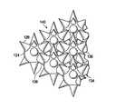
- FIG. 4Ais a schematic, perspective view of an illustrative, non-limiting embodiment of a microstrain-inducing manifold for use in treating a tissue site;
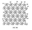
- FIG. 4Bis a schematic, top view of the microstrain-inducing manifold of FIG. 4A ;
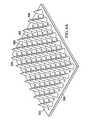
- FIG. 5Ais a schematic, perspective view of an illustrative, non-limiting embodiment of a microstrain-inducing manifold for use in treating a wound on a patient;
- FIG. 5Bis an enlarged partial view of the microstrain-inducing manifold of FIG. 5A ;
- FIG. 6Ais a schematic, perspective view of an illustrative, non-limiting embodiment of a microstrain-inducing manifold for use in treating a wound on a patient as part of an illustrative, non-limiting embodiment of a reduced-pressure wound treatment system;
- FIG. 6Bis an enlarged partial view of the microstrain-inducing manifold of FIG. 6A ;
- FIG. 7is a schematic, side view of an illustrative, non-limiting embodiment of a microstrain-inducing manifold.
- tissue site 103may, be, for example, a wound 102 , or damaged area of tissue, on a patient.
- the tissue site 103may be the bodily tissue of any human, animal, or other organism, including bone tissue, adipose tissue, muscle tissue, dermal tissue, vascular tissue, connective tissue, cartilage, tendons, ligaments, or any other tissue. Unless otherwise indicated, as used herein, “or” does not require mutual exclusivity.
- the reduced-pressure wound treatment system 100is shown in the context of the wound 102 , it will be appreciated that the reduced-pressure wound treatment system 100 may be used to treat many different types of tissue sites 103 and wounds including area wounds, incisions, internal wounds, or other tissue sites.
- the reduced-pressure wound treatment system 100is shown on the wound 102 , which is through the epidermis 104 , or generally skin, and the dermis 106 and reaching into a hypodermis, or subcutaneous tissue 108 .
- the reduced-pressure wound treatment system 100generally includes a sealing member 110 , a microstrain-inducing manifold 112 , and a reduced-pressure subsystem 114 .
- the microstrain-inducing manifold 112induces microstrain and may be referred to as a microstrain-inducing manifold.
- the microstrain-inducing manifold 112has a first side 113 and a second, patient-facing side 115 .
- microstrainresults from pressure distributed with the microstrain-inducing manifold 112 to a tissue site 103 , such as a wound surface 105 of the wound 102 . It is believed that this action creates areas of cell surface strain, or microdeformation.
- the cellsappear to respond to the strain by expressing special receptors on the surface of the cells and turning on genetic pathways in the cells, which promote healing activities.
- the healing activitiesmay include increased metabolic activity, stimulation of fibroblast migration, increased cellular proliferation, extra cellular matrix production, and the formation of granulation tissue, as well as a decrease in edema and a subsequent improvement of perfusion at the tissue site 103 .
- granulation tissuefills the wound 102 and thereby further reduces volume and prepares the wound 102 for final closure by secondary or delayed primary intention.
- the sealing member 110is generally formed from a flexible sheet.
- the sealing member 110includes a first surface 120 and a patient-facing surface 122 .
- the sealing member 110may be sized so that the sealing member 110 overlaps the wound 102 in such a manner that a drape extension 116 extends beyond the peripheral edge of the wound 102 .
- the sealing member 110may be formed from any material that provides a fluid seal.
- fluid sealor “seal,” means a seal adequate to maintain reduced pressure at a desired site, e.g., a tissue site, given the particular reduced-pressure source involved.
- the sealing membermay, for example, be an impermeable or semi-permeable, elastomeric material.
- “Elastomeric”means having the properties of an elastomer. Elastomeric generally refers to a polymeric material that has rubber-like properties. More specifically, most elastomers have ultimate elongations greater than 100% and a significant amount of resilience. The resilience of a material refers to the material's ability to recover from an elastic deformation.
- elastomersmay include, but are not limited to, natural rubbers, polyisoprene, styrene butadiene rubber, chloroprene rubber, polybutadiene, nitrile rubber, butyl rubber, ethylene propylene rubber, ethylene propylene diene monomer, chlorosulfonated polyethylene, polysulfide rubber, polyurethane, EVA film, co-polyester, and silicones.
- sealing member materialsinclude a silicone drape, 3M Tegaderm® drape, acrylic drape such as one available from Avery Dennison, or an incise drape.
- An attachment member 118 or devicemay be coupled to the sealing member 110 .
- the attachment member 118is operable to removably couple the sealing member 110 to a patient's epidermis 104 .
- the term “coupled”includes coupling via a separate object and includes direct coupling.
- the term “coupled”also encompasses two or more components that are continuous with one another by virtue of each of the components being formed from the same piece of material.
- the term “coupled”may include chemical, such as via a chemical bond, mechanical, thermal, or electrical coupling.
- Fluid couplingmeans that fluid is in communication between the designated parts or locations.
- the sealing member 110 and attachment member 118work together to form a fluid seal over the patient's epidermis 104 .
- the attachment member 118may be any material suitable to help couple the sealing member 110 to a patient's epidermis 104 .
- the attachment member 118may be a pressure-sensitive adhesive, heat-activated adhesive, sealing tape, double-sided sealing tape, paste, hydrocolloid, hydrogel, hooks, sutures, etc.
- the attachment member 118is an adhesive layer 119 coupled to the patient-facing surface 122 of the drape extension 116 .
- the attachment member 118may span the entire width or a portion of the patient-facing surface 122 of the sealing member 110 .
- the attachment member 118may be applied over the entire first surface 120 of the sealing member 110 , or over the first surface of the drape extensions 116 .
- the microstrain-inducing manifold 112is typically positioned between the second, patient-facing surface 122 of the sealing member 110 and the tissue site 103 , e.g., the wound 102 .
- the microstrain-inducing manifold 112may be sized to approximate the estimated area of the wound 102 , although a larger or smaller size may be used in different applications.
- the microstrain-inducing manifold 112includes a plurality of interconnected nodes 124 .
- the interconnected nodes 124may have a substantially circular cross-section, but it will be appreciated that the interconnected nodes 124 may have any suitable cross-section including, but not limited to, triangular, square, rectangular, hexagonal, octagonal, elliptical, etc.
- Each interconnected node 124may include one or more shaped projections 126 .
- the shaped projections 126are operable to create microstrain at the cellular level within the tissue site 103 , e.g., the wound 102 . While the illustrative embodiment shows each interconnected node 124 having a plurality of shaped projections 126 , it will be appreciated that some interconnected nodes 124 may be formed to avoid creating microstrains in certain areas. For example, one or more shaped projections 126 may be formed with a lower profile in a certain area or be absent all together in certain areas.
- an additional manifold with no shaped projectionse.g., a smooth, laminar manifold, may be placed between at least a portion of the shaped projections 126 of the microstrain-inducing manifold 112 and a portion of the tissue site 103 to prevent the creation of strain in a certain area. It is believed that avoiding microstrains in certain areas is helpful to overall patient care.
- microstrain-inducing manifold 112without projections 126 or that does not create microstrains in certain areas if a portion of the microstrain-inducing manifold 112 will lay on top of a vein, an artery, graft(s), objects used for adjunctive treatment or therapy (e.g., stents), exposed organs (e.g., heart or bowel), etc.
- objects used for adjunctive treatment or therapye.g., stents
- exposed organse.g., heart or bowel
- the shaped projections 126may be substantially the same size. Alternatively, some projections 126 may be larger or smaller than others. In one alternative, some shaped projections 126 may have a larger pitch than others, where “pitch” is defined by the angle 128 between a reference line 127 formed to have a right angle with a longitudinal axis 129 of the shaped projection 126 as shown in cross section in FIG. 3C . Each shaped projection 126 has an outer surface 130 and a base 132 .
- the shaped projections 126 in the illustrative embodimentare conical in shape, it will be appreciated that the shaped projections 126 may have any suitable shape capable of creating a microstrain within the wound 102 ; for example, the shaped projections 126 may be substantially cube shaped, pyramid shaped, hemispherically shaped, cylindrically shaped, triangularly shaped, cylindrically shaped with a distal recess, tapered, more elaborately shaped, etc.
- the shaped projections 126are typically angled or tapered from a thick proximal end to a thin distal end or vice versa.
- the shaped projections 126are formed of the same material as the interconnected nodes 124 .
- the shaped projections 126may be formed from a different material or the same material type of material with different properties than the interconnected nodes 124 or the other shaped projections 126 . Via material selection, one may control the stiffness of the interconnected nodes 124 such that greater microstrain may be provided in certain areas of the wound 102 versus others.
- the interconnected nodes 124 , shaped projections 126 , and the microstrain-inducing manifold 112generally may be formed of a foam material or a non-foam material.
- the interconnected nodes 124may be interconnected using a network of connecting members 134 .
- the network of connecting members 134may include a plurality of members 136 with each member 136 coupling adjacent interconnected nodes 124 to one another.
- the members 136have a substantially circular cross-section; however, it will be appreciated that the members 136 may have any suitable cross-section, including, but not limited to, triangular, square, rectangular, hexagonal, octagonal, elliptical, etc.
- the connecting members 134may be configured such that the microstrain-inducing manifold 112 behaves anisotropically when subjected to a reduced pressure.
- the interconnected nodes 124 , connecting members 134 , and shaped projections 126are arranged such that the microstrain-inducing manifold 112 includes a plurality of flow channels 140 ( FIG. 3B ) or pathways between the interconnected nodes 124 .
- the flow channels 140improve distribution of fluids provided to and removed from the area of tissue around the microstrain-inducing manifold 112 .
- the microstrain-inducing manifold 112is operable to assist in applying reduced pressure to, delivering fluids to, or removing fluids from a tissue site 103 .
- the design of microstrain-inducing manifold 112helps to avoid painful removal caused by in-growth, i.e., when growth of granulation tissue occurs into a manifold, and allows for easier removal from the tissue site 103 .
- the microstrain-inducing manifold 112may be formed from any suitable material.
- the microstrain-inducing manifold 112may be formed from an elastomer, a bioabsorbable/biodegradable polymer, etc.
- the manifold materialmay itself be, or may be combined with, a radio opaque material or a UV florescent material such that the wound 102 may be scanned with an X-ray or UV light in order to determine whether or not any remnants of the microstrain-inducing manifold 112 remain in the wound 102 after efforts have been made to remove the microstrain-inducing manifold 112 from the wound 102 .
- the shaped projections 126may be coated with a drug (e.g., an anticoagulant), an antimicrobial agent (e.g., silver or copper), a hydrophilic material, etc.
- a druge.g., an anticoagulant
- an antimicrobial agente.g., silver or copper
- a hydrophilic materiale.g., a hydrophilic material
- the microstrain-inducing manifold 112may also be formed with additional components, e.g., a delivery tube (not shown), whereby drugs or antimicrobial agents may be delivered to the wound 102 through the microstrain-inducing manifold 112 .
- the microstrain-inducing manifold 112may be formed by any suitable process, including, but not limited to, micromolding, injection molding, casting, etc.
- the shaped projections 126may be formed to be substantially integral with corresponding interconnected nodes 124 or may be coupled to corresponding interconnected nodes 124 by any suitable technique, including, but not limited to, mechanical fasteners, welding (e.g., ultrasonic or RF welding), bonding, adhesives, cements, etc.
- the microstrain-inducing manifold 112may include numerous devices for creating point pressure or otherwise inducing microstrain.
- the microstrain-inducing manifold 112includes limited contact points with the tissue site 103 . The contact points contribute to the inducement of microstrain at the tissue site 103 .
- the microstrain-inducing manifold 112 adjacent the tissue site 103may have a projection surface area of X cm 2 associated with the second, patient-facing side, and yet the portion of the microstrain-inducing manifold 112 directly impinging on the tissue site 103 may be less than 40 percent of the surface area X (40% X).
- projection surface areameans the area that a general projection of an item would make on a flat surface.
- the microstrain-inducing manifold 112 adjacent the tissue site 103may have a projection surface area of X cm 2 associated with the second, patient-facing side, and yet the portion of the microstrain-inducing manifold 112 directly impinging on the tissue site 103 may be less than 30 percent of the surface area X (30% X).
- the microstrain-inducing manifold 112 adjacent the tissue site 103may have a projection surface area of X cm 2 associated with the second, patient-facing side, and yet the portion of the microstrain-inducing manifold 112 directly impinging on the tissue site 103 may be less than 20 percent of the surface area X (20% X).
- the microstrain-inducing manifold 112 adjacent the tissue site 103may have a projection surface area of X cm 2 associated with the second, patient-facing side, and yet the portion of the microstrain-inducing manifold 112 directly impinging on the tissue site 103 may be less than 10 percent of the surface area X (10% X).
- the microstrain-inducing manifold 112 adjacent the tissue site 103may have a projection surface area of X cm 2 associated with the second, patient-facing side, and yet the portion of the microstrain-inducing manifold 112 directly impinging on the tissue site 103 may be less than 5 percent of the surface area X (5% X).
- the microstrain-inducing manifold 112 adjacent the tissue site 103may have a projection surface area of X cm 2 associated with the second, patient-facing side, and yet the portion of the microstrain-inducing manifold 112 directly impinging on the tissue site 103 may be less than 2 percent of the surface area X (2% X).
- the microstrain-inducing manifold 112 adjacent the tissue site 103may have a projection surface area of X cm 2 associated with the second, patient-facing side, and yet the portion of the microstrain-inducing manifold 112 directly impinging on the tissue site 103 may be less than 1 percent of the surface area X (1% X).
- the microstrain-inducing manifold 112 adjacent the tissue site 103may have a projection surface area of X cm 2 associated with the second, patient-facing side, and yet the portion of the microstrain-inducing manifold 112 directly impinging on the tissue site 103 may be less than 0.5 percent of the surface area X (0.5% X).
- the microstrain-inducing manifold 112 adjacent the tissue site 103may have a projection surface area of X cm 2 associated with the second, patient-facing side, and yet the portion of the microstrain-inducing manifold 112 directly impinging on the tissue site 103 may be less than 0.2 percent of the surface area X (0.2% X).
- the microstrain-inducing manifold 112 adjacent to tissue site 103 103may cover the wound surface 105 , and may have a projection surface area X, and yet the portion of microstrain-inducing manifold 112 directly impinging on the wound surface 105 may only be 0.2 percent of X.
- the impinging portionmay only be a portion of an outer surface 130 of each of the plurality of shaped projections 126 .
- the microstrain-inducing manifold 112may be disposed proximate the wound 102 such that the interconnected nodes 124 engage the wound surface 105 .
- the microstrain-inducing manifolds 112are stacked on top of one another to substantially fill the wound 102 .
- a single microstrain-inducing manifold 112may be employed or a multi-layer microstrain-inducing manifold may also be formed and used.
- the microstrain-inducing manifold 112may be formed from a single interconnected node 124 with a shaped projection 126 ; multiple independent interconnected nodes 124 with shaped projections 126 ; or a group of interconnected nodes 124 , which include shaped projections 126 , that are interconnected with the connecting members 134 .
- a single microstrain-inducing manifold 112may be rolled up or folded over itself in order to fill the wound 102 . Furthermore, it will be appreciated that a single microstrain-inducing manifold 112 may be loaded into the wound 102 and an additional manifold placed atop the manifold 112 . Examples of additional manifolds that may be placed atop the microstrain-inducing manifold 112 include, without limitation, devices that have structural elements arranged to form flow channels, cellular foam such as open-cell foam, porous tissue collections, and liquids, gels and foams that include or cure to include flow channels.
- the reduced-pressure subsystem 114includes a reduced-pressure source 142 , which may take many different forms.
- the reduced-pressure source 142provides reduced pressure as a part of the reduced-pressure wound treatment system 100 .
- reduced pressuregenerally refers to a pressure less than the ambient pressure at a tissue site that is being subjected to treatment. In most cases, this reduced pressure will be less than the atmospheric pressure at which the patient is located. Alternatively, the reduced pressure may be less than a hydrostatic pressure at the tissue site. Reduced pressure may initially generate fluid flow in the microstrain-inducing manifold 112 , a conduit 150 , and proximate the tissue site 103 .
- the reduced pressure deliveredmay be static or dynamic (patterned or random) and may be delivered continuously or intermittently.
- the reduced-pressure subsystem 114provides reduced pressure.
- the reduced-pressure subsystem 114includes a reduced-pressure source 142 that may be any source of a reduced pressure, such a vacuum pump, wall suction, etc. While the amount and nature of reduced pressure applied to a tissue site will typically vary according to the application, the reduced pressure will typically be between ⁇ 5 mm Hg and ⁇ 500 mm Hg. Pressure may be applied to the microstrain-inducing manifold 112 in other ways as well; for example, a pressure wrap may be used.
- the reduced-pressure source 142is shown having a battery compartment 144 and a canister region 146 with windows 148 providing a visual indication of the level of fluid within canister 146 .
- An interposed membrane filtersuch as hydrophobic or oleophobic filter, may be interspersed between the conduit 150 , or tubing, and the reduced-pressure source 142 .
- the reduced pressure supplied by the reduced-pressure source 142is delivered through the conduit 150 to a reduced-pressure interface 152 , which may be an elbow port 154 .
- the port 154is a TRAC® technology port available from Kinetic Concepts, Inc. of San Antonio, Tex.
- the reduced-pressure interface 152allows the reduced pressure to be delivered to the sealing member 110 and realized within an interior portion of sealing member 110 as well as the microstrain-inducing manifold 112 .
- the port 154extends through the sealing member 110 to the microstrain-inducing manifold 112 .
- the reduced-pressure wound treatment system 100may be applied to a patient's epidermis 104 over the tissue site 103 , e.g., wound 102 .
- the microstrain-inducing manifold 112may be disposed proximate the tissue site 103 , e.g., disposed within the wound 102 , or may overlay a portion of the wound 102 .
- the sealing member 110may be placed over the top of the microstrain-inducing manifold 112 such that drape extensions 116 extend beyond the periphery of the wound 102 .
- the drape extensions 116are secured to the patient's epidermis 104 (or a gasket member, such an additional piece of over drape surrounding the wound edges) by the attachment member 118 in order to form a fluid seal over the wound 102 .
- a fluid sealwith the patient's epidermis shall be deemed to also include forming a seal with a gasket proximate the wound 102 .
- the reduced-pressure interface 152is applied, if not already installed, and the conduit 150 fluidly coupled at one end to the reduced-pressure interface 152 .
- the other end of the conduit 150is fluidly coupled to the reduced-pressure source 142 .
- the reduced-pressure source 142may be activated such that reduced pressure is delivered to the sealing member 110 and microstrain-inducing manifold 112 .
- the reduced pressureprovides reduced-pressure treatment to the tissue site 103 , removes fluids, and may force the shaped projections 126 of the microstrain-inducing manifold 112 against the wound 102 such that they create a microstrain at the cellular level within the wound 102 .
- the microstrainmay promote cellular proliferation, formation of granular tissue, and other beneficial effects.
- the microstrain-inducing manifold 112may be placed proximate the tissue site 103 and then pressure may be applied by using a wrap over the microstrain-inducing manifold 112 or other source of pressure.
- microstrain-inducing manifold 212for use as part of a reduced-pressure wound treatment, such as the reduced-pressure wound treatment system 100 in FIG. 1 .
- the microstrain-inducing manifold 212includes interconnected nodes 224 , which include shaped projections 226 extending from the interconnected nodes 224 .
- the shaped projections 226are conical in shape; however, it will be appreciated that the shaped projections 226 may be any suitable shape capable of creating microstrain within a wound as previously discussed.
- each interconnected node 224 of the illustrative embodimentincludes two projections 226 (one directed up and one directed down for the orientation shown in FIG. 4A ), it will be appreciated that any number of projections 224 may extend from each interconnected node 224 or that some of the interconnected nodes 224 may have no projections 224 . Also, in the illustrative embodiment, each projection 226 extends substantially normal from a corresponding interconnected node 224 , but it will be appreciated that each projection 226 may extend from the corresponding interconnected node 224 at any angle.
- the interconnected nodes 224are spaced apart and interconnected by a network of connecting members 234 as clearly shown in FIG. 4B .
- the network of connecting members 234includes a plurality of curved members 236 .
- a plurality of flow channels 240are formed between the interconnected nodes 224 and members 236 .
- the members 236have curved surfaces 290 that are curved in a cooperative manner with one another or with the radius of one or more corresponding interconnected nodes 224 such that when the microstrain-inducing manifold 212 is subjected to a reduced pressure, the microstrain-inducing manifold 212 collapses (partially or fully) in two directions (e.g., along the x-axis 286 and y-axis 288 ) but not at all or to a lesser extent in a third direction (e.g., the z-axis 284 ).
- each curved surface 290 of each member 236abuts or approaches a curved surface 290 of an adjacent member 236 or at least one corresponding interconnected node 224 . This may be particularly advantageous if the reduced-pressure wound treatment system is configured to assist in drawing the wound together during reduced pressure therapy.
- a manifold structure 412which is a form of a microstrain-inducing manifold.
- the manifold structure 412is for use with a reduced-pressure wound treatment system, such as the reduced-pressure wound treatment system 100 of FIG. 1 , is shown.
- the manifold structure 412includes one or more longitudinal members 456 .
- the longitudinal members 456may be coupled in a spaced relationship by lateral connecting members 460 .
- the lateral connecting members 460may be coupled to the longitudinal members 456 .
- the longitudinal members 456 and lateral connecting members 460are shown with circular cross-sections, but it should be appreciated that the longitudinal members 456 and lateral connecting members 460 may have any suitable cross-sectional shape. While reference is made to longitudinal and lateral members, the members 456 , 460 need not be orthogonal but may have other relative angles.
- Each longitudinal member 456 of the manifold structure 412includes one or more shaped projections 426 for creating a microstrain within a wound.
- the longitudinal members 456 and shaped projections 426are arranged such that the manifold structure 412 includes a plurality of flow channels 440 or pathways between adjacent longitudinal members 456 or between projections 426 .
- the flow channels 440facilitate distribution of fluids provided to and removed from the area of tissue around the manifold structure 412 .
- any combination of longitudinal members 456 and lateral members 460may be used.
- the manifold structure 412may be formed by a longitudinally connected group of longitudinal members 456 with projections 426 . There are eight such longitudinal groups shown in FIG.
- lateral connecting members 460may be omitted in some embodiments.
- lateral connecting members 460may be distributed at various locations between the longitudinal members 456 .
- each shaped projection 426projects substantially normal from the corresponding longitudinal member 456 .
- “normal”is a vector which perpendicular to that surface. For a non-flat surface, the normal vector may be taken at a point and is the same as a normal to the tangent plane at that point. It should be appreciated, however, that each shaped projection 426 may project at any angle relative to the corresponding longitudinal member 456 .
- Each shaped projection 426may include a columnar body 427 , which has a first outer diameter (D 1 ), and an enlarged member 429 , which has a second outer diameter (D 2 ). Each enlarged member 429 is positioned at the distal end of an associated columnar body 427 .
- Each columnar body 429may have any shape, e.g., the cross-section may be a circular, square, elliptical, irregular, etc., and may vary along its longitudinal dimension.
- the enlarged member 429may be a spherical member as shown or may take any other shape, such as rounded cylindrical member, a cubical member, or an irregular shape.
- the second outer diameter (D 2 ) of the enlarged member 429is greater than the first outer diameter (D 1 ) of the columnar body 427 , i.e., D 2 >D 1 .
- the shaped projections 426may be considered to be tapered from a larger distal end to a smaller proximal end.
- Each shaped projection 426may have any suitable shape capable of creating a microstrain within the wound when the shaped projection 426 impinges upon the wound. Additionally, in the illustrative embodiment, the shaped projections 426 have substantially equal heights, but it will be appreciated that the shaped projections 426 may have varying heights along each longitudinal member 456 or among the plurality of longitudinal members 456 . Also, it will be appreciated that certain portions of certain longitudinal members 456 may not have shaped projections 426 such that microstrain is not provided to certain areas within the wound. As with the microstrain-inducing manifolds previously discussed, the manifold structure 412 may be formed using any suitable process, including, but not limited to, micromolding, injection molding, casting, etc.
- the shaped projections 426may be formed to be substantially integral with corresponding longitudinal members 456 or may be coupled to corresponding longitudinal members 456 by any suitable technique including, but not limited to, mechanical fasteners, welding (e.g., ultrasonic or RF welding), bonding, adhesives, cements, etc.
- the manifold structure 412is placed proximate the tissue site, e.g., wound, and a sealing member is deployed over the manifold structure 412 and tissue site. Reduced pressure may then be applied or alternatively a direct pressure may be applied.
- the manifold structure 412may behave anisotropically.
- the longitudinal members 456may move laterally towards each other. Each longitudinal member 456 move closer to an adjacent longitudinal member 456 than the adjacent longitudinal members 456 were prior to the introduction of the reduced pressure.
- the manifold structure 412does not substantially contract in a direction substantially parallel to the longitudinal members 456 .
- the manifold structure 412may deform more in a direction substantially perpendicular to the longitudinal members 456 (as illustrated by arrows 458 in FIG. 5A ) without a proportional deformation in the direction parallel with the longitudinal members 456 .
- the deformationis typically within the same plane. This may be advantageous if the system employs other components, such as an anisotropic drape or another manifold, for drawing the wound together during reduced pressure therapy wherein the illustrative manifold structure 412 contracts in a manner complimentary therewith. If spaced lateral connecting members 460 are used in sufficient number, very little contraction may take place.
- the manifold structure 412is configured such that some longitudinal members 456 are arranged substantially perpendicular to other longitudinal members 456 whereby the manifold structure 412 partially contracts, or contracts in a more limited manner, in two directions within the same plane when subjected to a reduced pressure.
- FIGS. 6A and 6Banother illustrative, non-limiting embodiment of a microstrain-inducing manifold 512 for use with a reduced-pressure wound treatment system, such as a reduced-pressure wound treatment system 100 ( FIG. 1 ), is shown.
- the microstrain-inducing manifold 512includes a mat 558 , or base, from which a plurality of shaped projections 526 extend.
- the mat 558has a first side 513 and a second, patient-facing side 515 .
- the shaped projections 526are tapered and in particular are substantially conical in shape, but it will be appreciated that the projections 526 may have any suitable shape capable of creating microstrain within the wound.
- the projections 526may extend from the mat 558 at any suitable angle.
- the projections 526have substantially equal heights, but the mat 558 may include projections 526 of varying heights. Portions of the mat 558 may not have any projections such that microstrain is not provided to certain areas within the wound. Additionally, the stiffness of the shaped projections 526 and pitch of the shaped projections 526 may vary along the mat 558 such that the microstrain created by the projections 526 may be greater in certain areas of the wound versus other areas.
- the shaped projections 526may be formed as integral portions of the mat 558 or coupled to the mat 558 by any suitable techniques, including but not limited to mechanical fasteners, welding (e.g., ultrasonic or RF welding), bonding, adhesives, cements, etc.
- the mat 558may also includes a plurality of apertures 560 ( FIG. 6B ) disposed between the projections 526 to improve the distribution of fluids provided to and removed from the area of tissue around the microstrain-inducing manifold 512 .
- the shaped projections 526may be formed from a modified honey on the mat 558 .
- the honeymay be modified so that it is solid or partially solid and retains its shape for at least a certain amount of time whilst engaging the wound.
- the honeymay act as an antimicrobial agent and may be absorbed by the patient after a period of time. Other dissolvable substances may be used as well.
- the microstrain-inducing manifold 512is typically placed proximate the tissue site with the second, patient-facing side 515 facing the patient and covered with a sealing member. Reduced pressure is then delivered to the microstrain-inducing manifold 512 . When subjected to a reduced pressure, the microstrain-inducing manifold 512 impinges on the wound whereby the shaped projections 526 create microstrain within the wound. Additionally, exudate and other fluids pass through the mat 558 via the apertures 560 . Also, in some instances, it may be desirable to avoid increasing microstrain within the wound via the shaped projections 526 .
- the microstrain-inducing manifold 512may be inverted such that the first side 513 of the mat 558 is placed against the wound and the shaped projections 526 extend towards the sealing member (not shown).
- the microstrain-inducing manifold 512may assist in perfusion and fluid removal (via the apertures 560 ) without also increasing microstrain within the wound via the shaped projections 526 .
- a microstrain-inducing manifold member 624 for use with a reduced-pressure wound treatment systemsuch as the reduced-pressure wound treatment system 100 in FIG. 1 , is shown.
- a microstrain-inducing manifoldmay be formed by a plurality of microstrain-inducing manifolds 624 .
- Each microstrain-inducing manifold member 624has one or more shaped projections 626 extending from a surface 631 .
- the microstrain-inducing manifold members 624are not interconnected by a network of connecting members.
- a plurality of microstrain-inducing manifold members 624may be poured into a wound whereby they work together to form the microstrain-inducing manifold in the wound (in situ) and whereby the shaped projections 626 of the microstrain-inducing manifold members 624 contact the wound to create microstrain therein.
- the plurality of microstrain-inducing manifold members 624may fill the entire wound.
- the plurality of microstrain-inducing manifold members 624may partially fill the wound, and, optionally, an alternative manifold may be placed atop the microstrain-inducing manifold members 624 to fill the wound.
- the microstrain-inducing manifold members 624may have a coating of material that allows the microstrain-inducing manifold members 624 to fuse or sinter in situ to one another and form a single, integral manifold.
- coatingsinclude the following: any water soluble, swellable, or softenable material, including polymers such as poly vinyl alcohol and its copolymer, polyvinyl pyrrolidone and its copolymers, polyethylene oxide and its copolymers, polypropylene oxide and its copolymers, hydroxyl, carboxyl, and sulphonyl containing polymers (e.g., hydroxyl ethyl acrylate, carboxyl methyl cellulose, acrylamido methyl propane sulphonic acid and its salts), alginates, gums (e.g. xanthan and guar), other hydrogels and hydrocolloids.
- polymerssuch as poly vinyl alcohol and its copolymer, polyvinyl pyrroli
Landscapes
- Health & Medical Sciences (AREA)
- Heart & Thoracic Surgery (AREA)
- Life Sciences & Earth Sciences (AREA)
- Veterinary Medicine (AREA)
- Public Health (AREA)
- General Health & Medical Sciences (AREA)
- Animal Behavior & Ethology (AREA)
- Biomedical Technology (AREA)
- Engineering & Computer Science (AREA)
- Vascular Medicine (AREA)
- Hematology (AREA)
- Anesthesiology (AREA)
- Rehabilitation Therapy (AREA)
- Epidemiology (AREA)
- Pain & Pain Management (AREA)
- Physical Education & Sports Medicine (AREA)
- Dermatology (AREA)
- Otolaryngology (AREA)
- Media Introduction/Drainage Providing Device (AREA)
- Surgical Instruments (AREA)
Abstract
Description
Claims (29)
Priority Applications (3)
| Application Number | Priority Date | Filing Date | Title |
|---|---|---|---|
| US13/963,809US9622915B2 (en) | 2008-12-24 | 2013-08-09 | Reduced-pressure wound treatment systems and methods employing microstrain-inducing manifolds |
| US15/448,793US10561768B2 (en) | 2008-12-24 | 2017-03-03 | Reduced-pressure wound treatment systems and methods employing microstrain-inducing manifolds |
| US16/733,055US20200147280A1 (en) | 2008-12-24 | 2020-01-02 | Reduced-Pressure Wound Treatment Systems And Methods Employing Microstrain-Inducing Manifolds |
Applications Claiming Priority (3)
| Application Number | Priority Date | Filing Date | Title |
|---|---|---|---|
| US14066208P | 2008-12-24 | 2008-12-24 | |
| US12/639,253US8529528B2 (en) | 2008-12-24 | 2009-12-16 | Reduced-pressure wound treatment systems and methods employing microstrain-inducing manifolds |
| US13/963,809US9622915B2 (en) | 2008-12-24 | 2013-08-09 | Reduced-pressure wound treatment systems and methods employing microstrain-inducing manifolds |
Related Parent Applications (1)
| Application Number | Title | Priority Date | Filing Date |
|---|---|---|---|
| US12/639,253ContinuationUS8529528B2 (en) | 2008-12-24 | 2009-12-16 | Reduced-pressure wound treatment systems and methods employing microstrain-inducing manifolds |
Related Child Applications (1)
| Application Number | Title | Priority Date | Filing Date |
|---|---|---|---|
| US15/448,793ContinuationUS10561768B2 (en) | 2008-12-24 | 2017-03-03 | Reduced-pressure wound treatment systems and methods employing microstrain-inducing manifolds |
Publications (2)
| Publication Number | Publication Date |
|---|---|
| US20130324951A1 US20130324951A1 (en) | 2013-12-05 |
| US9622915B2true US9622915B2 (en) | 2017-04-18 |
Family
ID=42267164
Family Applications (4)
| Application Number | Title | Priority Date | Filing Date |
|---|---|---|---|
| US12/639,253Active2031-09-23US8529528B2 (en) | 2008-12-24 | 2009-12-16 | Reduced-pressure wound treatment systems and methods employing microstrain-inducing manifolds |
| US13/963,809Active2032-04-02US9622915B2 (en) | 2008-12-24 | 2013-08-09 | Reduced-pressure wound treatment systems and methods employing microstrain-inducing manifolds |
| US15/448,793Active2031-03-13US10561768B2 (en) | 2008-12-24 | 2017-03-03 | Reduced-pressure wound treatment systems and methods employing microstrain-inducing manifolds |
| US16/733,055AbandonedUS20200147280A1 (en) | 2008-12-24 | 2020-01-02 | Reduced-Pressure Wound Treatment Systems And Methods Employing Microstrain-Inducing Manifolds |
Family Applications Before (1)
| Application Number | Title | Priority Date | Filing Date |
|---|---|---|---|
| US12/639,253Active2031-09-23US8529528B2 (en) | 2008-12-24 | 2009-12-16 | Reduced-pressure wound treatment systems and methods employing microstrain-inducing manifolds |
Family Applications After (2)
| Application Number | Title | Priority Date | Filing Date |
|---|---|---|---|
| US15/448,793Active2031-03-13US10561768B2 (en) | 2008-12-24 | 2017-03-03 | Reduced-pressure wound treatment systems and methods employing microstrain-inducing manifolds |
| US16/733,055AbandonedUS20200147280A1 (en) | 2008-12-24 | 2020-01-02 | Reduced-Pressure Wound Treatment Systems And Methods Employing Microstrain-Inducing Manifolds |
Country Status (13)
| Country | Link |
|---|---|
| US (4) | US8529528B2 (en) |
| EP (3) | EP3669850A1 (en) |
| JP (1) | JP5613173B2 (en) |
| KR (1) | KR20110116140A (en) |
| CN (1) | CN102264333B (en) |
| AU (2) | AU2009330298B2 (en) |
| BR (1) | BRPI0918310A2 (en) |
| CA (1) | CA2745695C (en) |
| MX (1) | MX2011006806A (en) |
| RU (1) | RU2011122962A (en) |
| SG (1) | SG172011A1 (en) |
| TW (1) | TW201029697A (en) |
| WO (1) | WO2010075179A2 (en) |
Cited By (1)
| Publication number | Priority date | Publication date | Assignee | Title |
|---|---|---|---|---|
| US20240082477A1 (en)* | 2011-06-24 | 2024-03-14 | 3M Innovative Properties Company | Reduced-pressure dressings employing tissue-fixation elements |
Families Citing this family (84)
| Publication number | Priority date | Publication date | Assignee | Title |
|---|---|---|---|---|
| JPH06105056B2 (en) | 1991-05-21 | 1994-12-21 | 株式会社神戸製鋼所 | Fuel compressor for gas turbine |
| US9820888B2 (en) | 2006-09-26 | 2017-11-21 | Smith & Nephew, Inc. | Wound dressing |
| GB0804654D0 (en)* | 2008-03-13 | 2008-04-16 | Smith & Nephew | Vacuum closure device |
| RU2011122550A (en)* | 2008-12-24 | 2013-01-27 | КейСиАй ЛАЙСЕНЗИНГ, ИНК. | MEMBRANES, SYSTEMS AND METHODS OF APPLICATION OF PRESSURE TO THE SUBCUTANEOUS TISSUE |
| GB0902368D0 (en) | 2009-02-13 | 2009-04-01 | Smith & Nephew | Wound packing |
| US8882730B2 (en) | 2010-03-12 | 2014-11-11 | Kci Licensing, Inc. | Radio opaque, reduced-pressure manifolds, systems, and methods |
| US9358158B2 (en)* | 2010-03-16 | 2016-06-07 | Kci Licensing, Inc. | Patterned neo-epithelialization dressings, systems, and methods |
| AU2012212070A1 (en) | 2011-02-04 | 2013-09-19 | University Of Massachusetts | Negative pressure wound closure device |
| US9421132B2 (en) | 2011-02-04 | 2016-08-23 | University Of Massachusetts | Negative pressure wound closure device |
| MX364446B (en) | 2011-04-15 | 2019-04-26 | Univ Massachusetts | Surgical cavity drainage and closure system. |
| RU2611760C2 (en)* | 2011-06-07 | 2017-02-28 | Смит Энд Нефью Плс | Wound contacting elements and methods of their use |
| CA2854634A1 (en)* | 2011-11-21 | 2013-05-30 | Kci Licensing, Inc. | Systems, devices, and methods for identifying portions of a wound filler left at a tissue site |
| US9125767B2 (en) | 2011-12-21 | 2015-09-08 | Kci Licensing, Inc. | Wound filler having dynamic motion |
| US10695471B2 (en) | 2012-02-13 | 2020-06-30 | Phase One Health, Llc | Wound dressing apparatus |
| JP6250571B2 (en) | 2012-03-12 | 2017-12-20 | スミス アンド ネフュー ピーエルシーSmith & Nephew Public Limited Company | Pressure reducing apparatus and method |
| EP2852419B1 (en) | 2012-05-22 | 2019-11-20 | Smith & Nephew plc | Wound closure device |
| EP2852333B1 (en) | 2012-05-22 | 2021-12-15 | Smith & Nephew plc | Apparatuses for wound therapy |
| AU2013264937B2 (en) | 2012-05-24 | 2018-04-19 | Smith & Nephew Inc. | Devices and methods for treating and closing wounds with negative pressure |
| MX369689B (en) | 2012-07-16 | 2019-11-19 | Smith & Nephew Inc | Negative pressure wound closure device. |
| BR112015002600A2 (en) | 2012-08-08 | 2017-07-04 | Smith & Nephew | custom-made wound care device and methods for use in negative pressure wound therapy |
| USD738487S1 (en)* | 2013-01-28 | 2015-09-08 | Molnlycke Health Care Ab | Suction device for negative pressure therapy |
| US10124098B2 (en) | 2013-03-13 | 2018-11-13 | Smith & Nephew, Inc. | Negative pressure wound closure device and systems and methods of use in treating wounds with negative pressure |
| BR112015021123A2 (en) | 2013-03-14 | 2017-07-18 | Smith & Nephew | compressible wound fillers and systems and methods for use in treating negative pressure injuries |
| JP6560201B2 (en)* | 2013-07-10 | 2019-08-14 | ケーシーアイ ライセンシング インコーポレイテッド | Manually regulated negative pressure pump with adapter for external pressure source |
| CA2918157A1 (en) | 2013-07-16 | 2015-01-22 | Smith & Nephew Plc | Apparatus for wound therapy |
| US10342891B2 (en)* | 2013-09-19 | 2019-07-09 | Medline Industries, Inc. | Wound dressing containing saccharide and collagen |
| CN106170275B (en) | 2013-10-21 | 2021-05-07 | 史密夫和内修有限公司 | Negative pressure wound closure device |
| EP3096725B1 (en) | 2014-01-21 | 2023-10-18 | Smith & Nephew plc | Wound treatment apparatuses |
| AU2015208299B2 (en) | 2014-01-21 | 2019-11-21 | Smith & Nephew Plc | Collapsible dressing for negative pressure wound treatment |
| JP2017512620A (en)* | 2014-03-28 | 2017-05-25 | スリーエム イノベイティブ プロパティズ カンパニー | Articles and methods for negative pressure wound closure therapy |
| US10898217B2 (en) | 2014-05-09 | 2021-01-26 | Kci Licensing, Inc. | Dressing providing apertures with multiple orifice sizes for negative-pressure therapy |
| WO2015172111A1 (en) | 2014-05-09 | 2015-11-12 | Kci Licensing, Inc. | Disruptive dressing for use with negative pressure and fluid instillation |
| WO2015172108A1 (en) | 2014-05-09 | 2015-11-12 | Kci Licensing, Inc. | Dressing with contracting layer for linear tissue sites |
| DK3288508T3 (en) | 2015-04-27 | 2020-03-09 | Smith & Nephew | REDUCED PRESSURE DEVICES |
| AU2016254119A1 (en) | 2015-04-29 | 2017-10-05 | Smith & Nephew Inc. | Negative pressure wound closure device |
| US10064273B2 (en) | 2015-10-20 | 2018-08-28 | MR Label Company | Antimicrobial copper sheet overlays and related methods for making and using |
| US10575991B2 (en) | 2015-12-15 | 2020-03-03 | University Of Massachusetts | Negative pressure wound closure devices and methods |
| US11471586B2 (en) | 2015-12-15 | 2022-10-18 | University Of Massachusetts | Negative pressure wound closure devices and methods |
| US10814049B2 (en) | 2015-12-15 | 2020-10-27 | University Of Massachusetts | Negative pressure wound closure devices and methods |
| EP3426206B1 (en) | 2016-03-07 | 2023-05-10 | Smith & Nephew plc | Wound treatment apparatuses and methods with negative pressure source integrated into wound dressing |
| CA3022184A1 (en) | 2016-04-26 | 2017-11-02 | Smith & Nephew Plc | Wound dressings and methods of use with integrated negative pressure source having a fluid ingress inhibition component |
| CA3038206A1 (en) | 2016-05-03 | 2017-11-09 | Smith & Nephew Plc | Optimizing power transfer to negative pressure sources in negative pressure therapy systems |
| US11096831B2 (en) | 2016-05-03 | 2021-08-24 | Smith & Nephew Plc | Negative pressure wound therapy device activation and control |
| WO2017191158A1 (en) | 2016-05-03 | 2017-11-09 | Smith & Nephew Plc | Systems and methods for driving negative pressure sources in negative pressure therapy systems |
| WO2018037075A1 (en) | 2016-08-25 | 2018-03-01 | Smith & Nephew Plc | Absorbent negative pressure wound therapy dressing |
| JP7038701B2 (en) | 2016-08-30 | 2022-03-18 | スミス アンド ネフュー ピーエルシー | System for applying decompression therapy |
| US11096832B2 (en) | 2016-09-27 | 2021-08-24 | Smith & Nephew Plc | Wound closure devices with dissolvable portions |
| EP3519001B1 (en) | 2016-09-30 | 2025-05-21 | Smith & Nephew plc | Negative pressure wound treatment apparatuses and methods with integrated electronics |
| CN110167495B (en) | 2016-11-02 | 2022-06-14 | 史密夫和内修有限公司 | Wound closure device |
| EP3551244A1 (en) | 2016-12-12 | 2019-10-16 | Smith & Nephew PLC | Pressure wound therapy status indication via external device |
| EP3592312B1 (en) | 2017-03-08 | 2024-01-10 | Smith & Nephew plc | Negative pressure wound therapy device control in presence of fault condition |
| WO2018191274A1 (en)* | 2017-04-11 | 2018-10-18 | University Of Florida Research Foundation | Systems and methods for in-situ, bottom-up tissue generation |
| JP7121050B2 (en) | 2017-05-09 | 2022-08-17 | スミス アンド ネフュー ピーエルシー | Redundant control of negative pressure wound therapy systems |
| AU201716716S (en) | 2017-05-11 | 2017-11-21 | MAƒA¶LNLYCKE HEALTH CARE AB | Wound dressings |
| WO2018229009A1 (en) | 2017-06-13 | 2018-12-20 | Smith & Nephew Plc | Wound closure device and method of use |
| EP3638169B1 (en) | 2017-06-13 | 2024-11-13 | Smith & Nephew PLC | Collapsible structure and method of use |
| AU2018285239B2 (en) | 2017-06-14 | 2023-09-21 | Smith & Nephew Plc | Collapsible sheet for wound closure and method of use |
| US11123476B2 (en) | 2017-06-14 | 2021-09-21 | Smith & Nephew, Inc. | Fluid removal management and control of wound closure in wound therapy |
| WO2018231874A1 (en) | 2017-06-14 | 2018-12-20 | Smith & Nephew, Inc. | Control of wound closure and fluid removal management in wound therapy |
| WO2018229011A1 (en) | 2017-06-14 | 2018-12-20 | Smith & Nephew Plc | Collapsible structure for wound closure and method of use |
| US10751212B2 (en)* | 2017-06-26 | 2020-08-25 | Maryam Raza | Multilayer dressing device and method for preventing and treating pressure ulcers and chronic wounds |
| WO2019020544A1 (en) | 2017-07-27 | 2019-01-31 | Smith & Nephew Plc | Customizable wound closure device and method of use |
| US11590030B2 (en) | 2017-08-07 | 2023-02-28 | Smith & Nephew Plc | Wound closure device with protective layer and method of use |
| EP3675925A1 (en) | 2017-08-29 | 2020-07-08 | Smith & Nephew PLC | Systems and methods for monitoring wound closure |
| CA3074780A1 (en) | 2017-09-13 | 2019-03-21 | Smith & Nephew Plc | Negative pressure wound treatment apparatuses and methods with integrated electronics |
| GB201718070D0 (en) | 2017-11-01 | 2017-12-13 | Smith & Nephew | Negative pressure wound treatment apparatuses and methods with integrated electronics |
| GB201718054D0 (en) | 2017-11-01 | 2017-12-13 | Smith & Nephew | Sterilization of integrated negative pressure wound treatment apparatuses and sterilization methods |
| GB201718072D0 (en) | 2017-11-01 | 2017-12-13 | Smith & Nephew | Negative pressure wound treatment apparatuses and methods with integrated electronics |
| US11497653B2 (en) | 2017-11-01 | 2022-11-15 | Smith & Nephew Plc | Negative pressure wound treatment apparatuses and methods with integrated electronics |
| JP7606347B2 (en)* | 2018-03-12 | 2024-12-25 | スリーエム イノベイティブ プロパティズ カンパニー | Dressing with different surface features used in compartmentalized spaces |
| EP3773385B1 (en)* | 2018-03-26 | 2025-02-12 | DeRoyal Industries, Inc. | Multi-lumen bridge for negative pressure wound therapy system |
| WO2020005535A1 (en)* | 2018-06-28 | 2020-01-02 | Kci Licensing, Inc. | A highly conformable wound dressing |
| EP3829515A1 (en)* | 2018-08-01 | 2021-06-09 | KCI Licensing, Inc. | Soft-tissue treatment with negative pressure |
| USD898925S1 (en) | 2018-09-13 | 2020-10-13 | Smith & Nephew Plc | Medical dressing |
| US20210338490A1 (en)* | 2018-10-17 | 2021-11-04 | Kci Licensing, Inc. | Systems, Apparatuses, And Methods For Negative-Pressure Treatment With Reduced Tissue In-Growth |
| JP2022506830A (en)* | 2018-11-08 | 2022-01-17 | ケーシーアイ ライセンシング インコーポレイテッド | Dressing with a protruding layer that allows cleaning of wound bed macrodeformations |
| CN113382700A (en)* | 2019-02-07 | 2021-09-10 | 凯希特许有限公司 | Contoured foam dressing shaped to provide negative pressure to an incision in a shoulder |
| GB201903774D0 (en) | 2019-03-20 | 2019-05-01 | Smith & Nephew | Negative pressure wound treatment apparatuses and methods with integrated electronics |
| GB201907716D0 (en) | 2019-05-31 | 2019-07-17 | Smith & Nephew | Systems and methods for extending operational time of negative pressure wound treatment apparatuses |
| CA3143830A1 (en)* | 2019-06-20 | 2020-12-24 | Kuo Huang YANG | Fluid-carrying application |
| US12409072B2 (en) | 2019-12-05 | 2025-09-09 | Kci Manufacturing Unlimited Company | Multi-layer negative pressure incisional wound therapy dressing |
| US11160917B2 (en) | 2020-01-22 | 2021-11-02 | J&M Shuler Medical Inc. | Negative pressure wound therapy barrier |
| CN116367800A (en)* | 2020-07-30 | 2023-06-30 | 3M创新知识产权公司 | low ingrowth tissue interface |
| USD1043997S1 (en)* | 2020-09-18 | 2024-09-24 | Jake Timothy | Compression wound dressing |
Citations (132)
| Publication number | Priority date | Publication date | Assignee | Title |
|---|---|---|---|---|
| US1355846A (en) | 1920-02-06 | 1920-10-19 | David A Rannells | Medical appliance |
| US2547758A (en) | 1949-01-05 | 1951-04-03 | Wilmer B Keeling | Instrument for treating the male urethra |
| US2632443A (en) | 1949-04-18 | 1953-03-24 | Eleanor P Lesher | Surgical dressing |
| GB692578A (en) | 1949-09-13 | 1953-06-10 | Minnesota Mining & Mfg | Improvements in or relating to drape sheets for surgical use |
| US2682873A (en) | 1952-07-30 | 1954-07-06 | Johnson & Johnson | General purpose protective dressing |
| US2910763A (en) | 1955-08-17 | 1959-11-03 | Du Pont | Felt-like products |
| US2969057A (en) | 1957-11-04 | 1961-01-24 | Brady Co W H | Nematodic swab |
| US3066672A (en) | 1960-09-27 | 1962-12-04 | Jr William H Crosby | Method and apparatus for serial sampling of intestinal juice |
| US3367332A (en) | 1965-08-27 | 1968-02-06 | Gen Electric | Product and process for establishing a sterile area of skin |
| US3520300A (en) | 1967-03-15 | 1970-07-14 | Amp Inc | Surgical sponge and suction device |
| US3568675A (en) | 1968-08-30 | 1971-03-09 | Clyde B Harvey | Fistula and penetrating wound dressing |
| US3648692A (en) | 1970-12-07 | 1972-03-14 | Parke Davis & Co | Medical-surgical dressing for burns and the like |
| US3682180A (en) | 1970-06-08 | 1972-08-08 | Coilform Co Inc | Drain clip for surgical drain |
| US3826254A (en) | 1973-02-26 | 1974-07-30 | Verco Ind | Needle or catheter retaining appliance |
| DE2640413A1 (en) | 1976-09-08 | 1978-03-09 | Wolf Gmbh Richard | CATHETER MONITORING DEVICE |
| US4080970A (en) | 1976-11-17 | 1978-03-28 | Miller Thomas J | Post-operative combination dressing and internal drain tube with external shield and tube connector |
| US4096853A (en) | 1975-06-21 | 1978-06-27 | Hoechst Aktiengesellschaft | Device for the introduction of contrast medium into an anus praeter |
| US4139004A (en) | 1977-02-17 | 1979-02-13 | Gonzalez Jr Harry | Bandage apparatus for treating burns |
| US4165748A (en) | 1977-11-07 | 1979-08-28 | Johnson Melissa C | Catheter tube holder |
| US4184510A (en) | 1977-03-15 | 1980-01-22 | Fibra-Sonics, Inc. | Valued device for controlling vacuum in surgery |
| WO1980002182A1 (en) | 1979-04-06 | 1980-10-16 | J Moss | Portable suction device for collecting fluids from a closed wound |
| US4233969A (en) | 1976-11-11 | 1980-11-18 | Lock Peter M | Wound dressing materials |
| US4245630A (en) | 1976-10-08 | 1981-01-20 | T. J. Smith & Nephew, Ltd. | Tearable composite strip of materials |
| US4256109A (en) | 1978-07-10 | 1981-03-17 | Nichols Robert L | Shut off valve for medical suction apparatus |
| US4261363A (en) | 1979-11-09 | 1981-04-14 | C. R. Bard, Inc. | Retention clips for body fluid drains |
| US4275721A (en) | 1978-11-28 | 1981-06-30 | Landstingens Inkopscentral Lic, Ekonomisk Forening | Vein catheter bandage |
| US4284079A (en) | 1979-06-28 | 1981-08-18 | Adair Edwin Lloyd | Method for applying a male incontinence device |
| US4297995A (en) | 1980-06-03 | 1981-11-03 | Key Pharmaceuticals, Inc. | Bandage containing attachment post |
| US4333468A (en) | 1980-08-18 | 1982-06-08 | Geist Robert W | Mesentery tube holder apparatus |
| US4373519A (en) | 1981-06-26 | 1983-02-15 | Minnesota Mining And Manufacturing Company | Composite wound dressing |
| US4382441A (en) | 1978-12-06 | 1983-05-10 | Svedman Paul | Device for treating tissues, for example skin |
| US4392858A (en) | 1981-07-16 | 1983-07-12 | Sherwood Medical Company | Wound drainage device |
| US4392853A (en) | 1981-03-16 | 1983-07-12 | Rudolph Muto | Sterile assembly for protecting and fastening an indwelling device |
| US4419097A (en) | 1981-07-31 | 1983-12-06 | Rexar Industries, Inc. | Attachment for catheter tube |
| EP0100148A1 (en) | 1982-07-06 | 1984-02-08 | Dow Corning Limited | Medical-surgical dressing and a process for the production thereof |
| US4465485A (en) | 1981-03-06 | 1984-08-14 | Becton, Dickinson And Company | Suction canister with unitary shut-off valve and filter features |
| EP0117632A2 (en) | 1983-01-27 | 1984-09-05 | Johnson & Johnson Products Inc. | Adhesive film dressing |
| US4475909A (en) | 1982-05-06 | 1984-10-09 | Eisenberg Melvin I | Male urinary device and method for applying the device |
| US4480638A (en) | 1980-03-11 | 1984-11-06 | Eduard Schmid | Cushion for holding an element of grafted skin |
| US4525166A (en) | 1981-11-21 | 1985-06-25 | Intermedicat Gmbh | Rolled flexible medical suction drainage device |
| US4525374A (en) | 1984-02-27 | 1985-06-25 | Manresa, Inc. | Treating hydrophobic filters to render them hydrophilic |
| US4540412A (en) | 1983-07-14 | 1985-09-10 | The Kendall Company | Device for moist heat therapy |
| US4543100A (en) | 1983-11-01 | 1985-09-24 | Brodsky Stuart A | Catheter and drain tube retainer |
| US4548202A (en) | 1983-06-20 | 1985-10-22 | Ethicon, Inc. | Mesh tissue fasteners |
| US4551139A (en) | 1982-02-08 | 1985-11-05 | Marion Laboratories, Inc. | Method and apparatus for burn wound treatment |
| EP0161865A2 (en) | 1984-05-03 | 1985-11-21 | Smith and Nephew Associated Companies p.l.c. | Adhesive wound dressing |
| US4569348A (en) | 1980-02-22 | 1986-02-11 | Velcro Usa Inc. | Catheter tube holder strap |
| AU550575B2 (en) | 1981-08-07 | 1986-03-27 | Richard Christian Wright | Wound drainage device |
| US4605399A (en) | 1984-12-04 | 1986-08-12 | Complex, Inc. | Transdermal infusion device |
| US4608041A (en) | 1981-10-14 | 1986-08-26 | Frese Nielsen | Device for treatment of wounds in body tissue of patients by exposure to jets of gas |
| US4640688A (en) | 1985-08-23 | 1987-02-03 | Mentor Corporation | Urine collection catheter |
| US4655754A (en) | 1984-11-09 | 1987-04-07 | Stryker Corporation | Vacuum wound drainage system and lipids baffle therefor |
| US4664662A (en) | 1984-08-02 | 1987-05-12 | Smith And Nephew Associated Companies Plc | Wound dressing |
| WO1987004626A1 (en) | 1986-01-31 | 1987-08-13 | Osmond, Roger, L., W. | Suction system for wound and gastro-intestinal drainage |
| US4710165A (en) | 1985-09-16 | 1987-12-01 | Mcneil Charles B | Wearable, variable rate suction/collection device |
| US4733659A (en) | 1986-01-17 | 1988-03-29 | Seton Company | Foam bandage |
| GB2195255A (en) | 1986-09-30 | 1988-04-07 | Vacutec Uk Limited | Method and apparatus for vacuum treatment of an epidermal surface |
| US4743232A (en) | 1986-10-06 | 1988-05-10 | The Clinipad Corporation | Package assembly for plastic film bandage |
| GB2197789A (en) | 1986-11-28 | 1988-06-02 | Smiths Industries Plc | Anti-foaming disinfectants used in surgical suction apparatus |
| US4758220A (en) | 1985-09-26 | 1988-07-19 | Alcon Laboratories, Inc. | Surgical cassette proximity sensing and latching apparatus |
| US4787888A (en) | 1987-06-01 | 1988-11-29 | University Of Connecticut | Disposable piezoelectric polymer bandage for percutaneous delivery of drugs and method for such percutaneous delivery (a) |
| US4826494A (en) | 1984-11-09 | 1989-05-02 | Stryker Corporation | Vacuum wound drainage system |
| US4838883A (en) | 1986-03-07 | 1989-06-13 | Nissho Corporation | Urine-collecting device |
| US4840187A (en) | 1986-09-11 | 1989-06-20 | Bard Limited | Sheath applicator |
| US4863449A (en) | 1987-07-06 | 1989-09-05 | Hollister Incorporated | Adhesive-lined elastic condom cathether |
| US4872450A (en) | 1984-08-17 | 1989-10-10 | Austad Eric D | Wound dressing and method of forming same |
| US4878901A (en) | 1986-10-10 | 1989-11-07 | Sachse Hans Ernst | Condom catheter, a urethral catheter for the prevention of ascending infections |
| GB2220357A (en) | 1988-05-28 | 1990-01-10 | Smiths Industries Plc | Medico-surgical containers |
| US4897081A (en) | 1984-05-25 | 1990-01-30 | Thermedics Inc. | Percutaneous access device |
| US4906240A (en) | 1988-02-01 | 1990-03-06 | Matrix Medica, Inc. | Adhesive-faced porous absorbent sheet and method of making same |
| US4906233A (en) | 1986-05-29 | 1990-03-06 | Terumo Kabushiki Kaisha | Method of securing a catheter body to a human skin surface |
| US4919654A (en) | 1988-08-03 | 1990-04-24 | Kalt Medical Corporation | IV clamp with membrane |
| CA2005436A1 (en) | 1988-12-13 | 1990-06-13 | Glenda G. Kalt | Transparent tracheostomy tube dressing |
| US4941882A (en) | 1987-03-14 | 1990-07-17 | Smith And Nephew Associated Companies, P.L.C. | Adhesive dressing for retaining a cannula on the skin |
| US4953565A (en) | 1986-11-26 | 1990-09-04 | Shunro Tachibana | Endermic application kits for external medicines |
| WO1990010424A1 (en) | 1989-03-16 | 1990-09-20 | Smith & Nephew Plc | Absorbent devices and precursors therefor |
| US4969880A (en) | 1989-04-03 | 1990-11-13 | Zamierowski David S | Wound dressing and treatment method |
| US4985019A (en) | 1988-03-11 | 1991-01-15 | Michelson Gary K | X-ray marker |
| GB2235877A (en) | 1989-09-18 | 1991-03-20 | Antonio Talluri | Closed wound suction apparatus |
| US5037397A (en) | 1985-05-03 | 1991-08-06 | Medical Distributors, Inc. | Universal clamp |
| US5086170A (en) | 1989-01-16 | 1992-02-04 | Roussel Uclaf | Process for the preparation of azabicyclo compounds |
| US5092858A (en) | 1990-03-20 | 1992-03-03 | Becton, Dickinson And Company | Liquid gelling agent distributor device |
| US5100396A (en) | 1989-04-03 | 1992-03-31 | Zamierowski David S | Fluidic connection system and method |
| JPH04129536A (en) | 1990-09-19 | 1992-04-30 | Terumo Corp | Balance device |
| US5134994A (en) | 1990-02-12 | 1992-08-04 | Say Sam L | Field aspirator in a soft pack with externally mounted container |
| US5149331A (en) | 1991-05-03 | 1992-09-22 | Ariel Ferdman | Method and device for wound closure |
| US5167613A (en) | 1992-03-23 | 1992-12-01 | The Kendall Company | Composite vented wound dressing |
| US5176663A (en) | 1987-12-02 | 1993-01-05 | Pal Svedman | Dressing having pad with compressibility limiting elements |
| WO1993009727A1 (en) | 1991-11-14 | 1993-05-27 | Wake Forest University | Method and apparatus for treating tissue damage |
| US5215522A (en) | 1984-07-23 | 1993-06-01 | Ballard Medical Products | Single use medical aspirating device and method |
| US5232453A (en) | 1989-07-14 | 1993-08-03 | E. R. Squibb & Sons, Inc. | Catheter holder |
| US5261893A (en) | 1989-04-03 | 1993-11-16 | Zamierowski David S | Fastening system and method |
| US5278100A (en) | 1991-11-08 | 1994-01-11 | Micron Technology, Inc. | Chemical vapor deposition technique for depositing titanium silicide on semiconductor wafers |
| US5279550A (en) | 1991-12-19 | 1994-01-18 | Gish Biomedical, Inc. | Orthopedic autotransfusion system |
| US5298015A (en) | 1989-07-11 | 1994-03-29 | Nippon Zeon Co., Ltd. | Wound dressing having a porous structure |
| US5342376A (en) | 1993-05-03 | 1994-08-30 | Dermagraphics, Inc. | Inserting device for a barbed tissue connector |
| US5344415A (en) | 1993-06-15 | 1994-09-06 | Deroyal Industries, Inc. | Sterile system for dressing vascular access site |
| DE4306478A1 (en) | 1993-03-02 | 1994-09-08 | Wolfgang Dr Wagner | Drainage device, in particular pleural drainage device, and drainage method |
| WO1994020041A1 (en) | 1993-03-09 | 1994-09-15 | Wake Forest University | Wound treatment employing reduced pressure |
| US5358494A (en) | 1989-07-11 | 1994-10-25 | Svedman Paul | Irrigation dressing |
| US5437651A (en) | 1993-09-01 | 1995-08-01 | Research Medical, Inc. | Medical suction apparatus |
| US5437622A (en) | 1992-04-29 | 1995-08-01 | Laboratoire Hydrex (Sa) | Transparent adhesive dressing with reinforced starter cuts |
| DE29504378U1 (en) | 1995-03-15 | 1995-09-14 | MTG Medizinisch, technische Gerätebau GmbH, 66299 Friedrichsthal | Electronically controlled low-vacuum pump for chest and wound drainage |
| WO1996005873A1 (en) | 1994-08-22 | 1996-02-29 | Kinetic Concepts Inc. | Wound drainage equipment |
| US5527293A (en) | 1989-04-03 | 1996-06-18 | Kinetic Concepts, Inc. | Fastening system and method |
| US5549584A (en) | 1994-02-14 | 1996-08-27 | The Kendall Company | Apparatus for removing fluid from a wound |
| US5556375A (en) | 1994-06-16 | 1996-09-17 | Hercules Incorporated | Wound dressing having a fenestrated base layer |
| US5607388A (en) | 1994-06-16 | 1997-03-04 | Hercules Incorporated | Multi-purpose wound dressing |
| WO1997018007A1 (en) | 1995-11-14 | 1997-05-22 | Kci Medical Limited | Portable wound treatment apparatus |
| WO1999013793A1 (en) | 1997-09-12 | 1999-03-25 | Kci Medical Limited | Surgical drape and suction head for wound treatment |
| US6071267A (en) | 1998-02-06 | 2000-06-06 | Kinetic Concepts, Inc. | Medical patient fluid management interface system and method |
| US6135116A (en) | 1997-07-28 | 2000-10-24 | Kci Licensing, Inc. | Therapeutic method for treating ulcers |
| US6241747B1 (en) | 1993-05-03 | 2001-06-05 | Quill Medical, Inc. | Barbed Bodily tissue connector |
| US6287316B1 (en) | 1999-03-26 | 2001-09-11 | Ethicon, Inc. | Knitted surgical mesh |
| US20020077661A1 (en) | 2000-12-20 | 2002-06-20 | Vahid Saadat | Multi-barbed device for retaining tissue in apposition and methods of use |
| US20020115951A1 (en) | 2001-02-22 | 2002-08-22 | Core Products International, Inc. | Ankle brace providing upper and lower ankle adjustment |
| US20020120185A1 (en) | 2000-05-26 | 2002-08-29 | Kci Licensing, Inc. | System for combined transcutaneous blood gas monitoring and vacuum assisted wound closure |
| US20020143286A1 (en) | 2001-03-05 | 2002-10-03 | Kci Licensing, Inc. | Vacuum assisted wound treatment apparatus and infection identification system and method |
| US6488643B1 (en) | 1998-10-08 | 2002-12-03 | Kci Licensing, Inc. | Wound healing foot wrap |
| US6493568B1 (en) | 1994-07-19 | 2002-12-10 | Kci Licensing, Inc. | Patient interface system |
| US20050209574A1 (en) | 2004-03-18 | 2005-09-22 | Boehringer Laboratories, Inc. | Wound packing material for use with suction |
| US20060041247A1 (en) | 2002-08-21 | 2006-02-23 | Robert Petrosenko | Wound packing for preventing wound closure |
| US20070185426A1 (en) | 2001-02-16 | 2007-08-09 | Kci Licensing, Inc. | Biocompatible wound dressing |
| US20070185463A1 (en)* | 2006-02-07 | 2007-08-09 | Tyco Heal Thcare Group Lp | Surgical wound dressing |
| US20070203442A1 (en)* | 2004-01-09 | 2007-08-30 | Bio-Gate Ag | Wound Covering |
| WO2008039223A1 (en) | 2006-09-26 | 2008-04-03 | Boehringer Technologies L.P. | Pump system for negative pressure wound therapy |
| US20080177253A1 (en) | 2004-04-13 | 2008-07-24 | Boehringer Laboratories Inc. | Growth stimulating wound dressing with improved contact surfaces |
| JP4129536B2 (en) | 2000-02-24 | 2008-08-06 | ヴェネテック インターナショナル,インコーポレイテッド | Highly compatible catheter anchoring system |
| WO2008104609A1 (en) | 2007-03-01 | 2008-09-04 | Coloplast A/S | Pressure-distributing elements for use with negative pressure therapy |
| US20080275409A1 (en)* | 2007-05-01 | 2008-11-06 | The Brigham And Women's Hospital, Inc. | Wound healing device |
| US20100262096A1 (en)* | 2007-12-08 | 2010-10-14 | Smith & Nephew Plc | Wound packing members |
| US20100268177A1 (en)* | 2007-12-08 | 2010-10-21 | Smith & Nephew Plc | Wound fillers |
Family Cites Families (28)
| Publication number | Priority date | Publication date | Assignee | Title |
|---|---|---|---|---|
| US2930377A (en)* | 1958-06-02 | 1960-03-29 | Baxter Don Inc | Surgical tube |
| US3407817A (en) | 1965-07-26 | 1968-10-29 | Air Reduction Inc | Catheter with cuff inflater and indicator |
| US3630206A (en) | 1970-01-02 | 1971-12-28 | Bruce Gingold | Bladder catheter |
| US3599641A (en)* | 1970-03-13 | 1971-08-17 | David S Sheridan | Combination connector and channel closure system for catheters |
| US4398910A (en)* | 1981-02-26 | 1983-08-16 | Blake L W | Wound drain catheter |
| SE8103617L (en)* | 1981-06-09 | 1982-12-10 | Meteve Ab | CATS FOR POST-OPERATIVE DRAINAGE |
| GB9225581D0 (en)* | 1992-12-08 | 1993-01-27 | Courtaulds Plc | Wound dressings |
| GB9411429D0 (en) | 1994-06-08 | 1994-07-27 | Seton Healthcare Group Plc | Wound dressings |
| US6099513A (en)* | 1996-08-27 | 2000-08-08 | Allegiance Corporation | Wound drain with alternating perimetrically arranged lumens and ducts |
| NL1006457C2 (en) | 1997-07-03 | 1999-01-05 | Polymedics N V | Drainage system to be used with an open wound, element used for applying a drainage pipe or hose and method for applying the drainage system. |
| US7273054B2 (en)* | 1997-09-12 | 2007-09-25 | Kci Licensing, Inc. | Surgical drape and head for wound treatment |
| AU755496B2 (en) | 1997-09-12 | 2002-12-12 | Kci Licensing, Inc. | Surgical drape and suction head for wound treatment |
| US6478789B1 (en) | 1999-11-15 | 2002-11-12 | Allegiance Corporation | Wound drain with portals to enable uniform suction |
| US6685681B2 (en)* | 2000-11-29 | 2004-02-03 | Hill-Rom Services, Inc. | Vacuum therapy and cleansing dressing for wounds |
| US7004915B2 (en)* | 2001-08-24 | 2006-02-28 | Kci Licensing, Inc. | Negative pressure assisted tissue treatment system |
| US7846141B2 (en)* | 2002-09-03 | 2010-12-07 | Bluesky Medical Group Incorporated | Reduced pressure treatment system |
| US6979324B2 (en)* | 2002-09-13 | 2005-12-27 | Neogen Technologies, Inc. | Closed wound drainage system |
| JP4448093B2 (en)* | 2002-12-31 | 2010-04-07 | ベーエスエヌ・メディカル・ゲーエムベーハー | Wound dressing |
| GB0409443D0 (en)* | 2004-04-28 | 2004-06-02 | Smith & Nephew | Apparatus |
| US7884258B2 (en)* | 2004-04-13 | 2011-02-08 | Boehringer Technologies, L.P. | Wound contact device |
| GB2415382A (en)* | 2004-06-21 | 2005-12-28 | Johnson & Johnson Medical Ltd | Wound dressings for vacuum therapy |
| US7438705B2 (en)* | 2005-07-14 | 2008-10-21 | Boehringer Technologies, L.P. | System for treating a wound with suction and method detecting loss of suction |
| US7879615B2 (en)* | 2005-10-20 | 2011-02-01 | Coramed Technologies, Llc | Hemostasis analyzer and method |
| CN101360473B (en) | 2006-01-23 | 2011-12-14 | 凯希特许有限公司 | System for treating wounds using ultrasonic debridement |
| EP1986718B1 (en) | 2006-02-06 | 2015-10-28 | KCI Licensing, Inc. | Systems for improved connection to wound dressings in conjunction with reduced pressure wound treatment systems |
| WO2008060475A2 (en)* | 2006-11-09 | 2008-05-22 | Kci Licensing Inc. | Porous bioresorbable linked dressing comprising microspheres and methods of making same |
| CN101678156B (en)* | 2007-05-10 | 2013-05-22 | 凯希特许有限公司 | Reduced pressure wound dressing having a wound contact surface with columnar protrusions |
| CN102036699B (en)* | 2008-05-30 | 2013-08-21 | 凯希特许有限公司 | Decompression Linear Wound Therapy System |
- 2009
- 2009-12-16USUS12/639,253patent/US8529528B2/enactiveActive
- 2009-12-17BRBRPI0918310Apatent/BRPI0918310A2/ennot_activeIP Right Cessation
- 2009-12-17RURU2011122962/14Apatent/RU2011122962A/ennot_activeApplication Discontinuation
- 2009-12-17AUAU2009330298Apatent/AU2009330298B2/ennot_activeCeased
- 2009-12-17WOPCT/US2009/068544patent/WO2010075179A2/enactiveApplication Filing
- 2009-12-17EPEP20150173.1Apatent/EP3669850A1/ennot_activeWithdrawn
- 2009-12-17JPJP2011543594Apatent/JP5613173B2/enactiveActive
- 2009-12-17EPEP09835646.2Apatent/EP2367518B1/enactiveActive
- 2009-12-17SGSG2011041555Apatent/SG172011A1/enunknown
- 2009-12-17EPEP17197927.1Apatent/EP3292854B1/enactiveActive
- 2009-12-17KRKR1020117017298Apatent/KR20110116140A/ennot_activeCeased
- 2009-12-17CNCN200980151961.XApatent/CN102264333B/enactiveActive
- 2009-12-17MXMX2011006806Apatent/MX2011006806A/ennot_activeApplication Discontinuation
- 2009-12-17CACA2745695Apatent/CA2745695C/enactiveActive
- 2009-12-24TWTW098144834Apatent/TW201029697A/enunknown
- 2013
- 2013-08-09USUS13/963,809patent/US9622915B2/enactiveActive
- 2015
- 2015-12-31AUAU2015285968Apatent/AU2015285968B2/ennot_activeCeased
- 2017
- 2017-03-03USUS15/448,793patent/US10561768B2/enactiveActive
- 2020
- 2020-01-02USUS16/733,055patent/US20200147280A1/ennot_activeAbandoned
Patent Citations (141)
| Publication number | Priority date | Publication date | Assignee | Title |
|---|---|---|---|---|
| US1355846A (en) | 1920-02-06 | 1920-10-19 | David A Rannells | Medical appliance |
| US2547758A (en) | 1949-01-05 | 1951-04-03 | Wilmer B Keeling | Instrument for treating the male urethra |
| US2632443A (en) | 1949-04-18 | 1953-03-24 | Eleanor P Lesher | Surgical dressing |
| GB692578A (en) | 1949-09-13 | 1953-06-10 | Minnesota Mining & Mfg | Improvements in or relating to drape sheets for surgical use |
| US2682873A (en) | 1952-07-30 | 1954-07-06 | Johnson & Johnson | General purpose protective dressing |
| US2910763A (en) | 1955-08-17 | 1959-11-03 | Du Pont | Felt-like products |
| US2969057A (en) | 1957-11-04 | 1961-01-24 | Brady Co W H | Nematodic swab |
| US3066672A (en) | 1960-09-27 | 1962-12-04 | Jr William H Crosby | Method and apparatus for serial sampling of intestinal juice |
| US3367332A (en) | 1965-08-27 | 1968-02-06 | Gen Electric | Product and process for establishing a sterile area of skin |
| US3520300A (en) | 1967-03-15 | 1970-07-14 | Amp Inc | Surgical sponge and suction device |
| US3568675A (en) | 1968-08-30 | 1971-03-09 | Clyde B Harvey | Fistula and penetrating wound dressing |
| US3682180A (en) | 1970-06-08 | 1972-08-08 | Coilform Co Inc | Drain clip for surgical drain |
| US3648692A (en) | 1970-12-07 | 1972-03-14 | Parke Davis & Co | Medical-surgical dressing for burns and the like |
| US3826254A (en) | 1973-02-26 | 1974-07-30 | Verco Ind | Needle or catheter retaining appliance |
| US4096853A (en) | 1975-06-21 | 1978-06-27 | Hoechst Aktiengesellschaft | Device for the introduction of contrast medium into an anus praeter |
| DE2640413A1 (en) | 1976-09-08 | 1978-03-09 | Wolf Gmbh Richard | CATHETER MONITORING DEVICE |
| US4245630A (en) | 1976-10-08 | 1981-01-20 | T. J. Smith & Nephew, Ltd. | Tearable composite strip of materials |
| US4233969A (en) | 1976-11-11 | 1980-11-18 | Lock Peter M | Wound dressing materials |
| US4080970A (en) | 1976-11-17 | 1978-03-28 | Miller Thomas J | Post-operative combination dressing and internal drain tube with external shield and tube connector |
| US4139004A (en) | 1977-02-17 | 1979-02-13 | Gonzalez Jr Harry | Bandage apparatus for treating burns |
| US4184510A (en) | 1977-03-15 | 1980-01-22 | Fibra-Sonics, Inc. | Valued device for controlling vacuum in surgery |
| US4165748A (en) | 1977-11-07 | 1979-08-28 | Johnson Melissa C | Catheter tube holder |
| US4256109A (en) | 1978-07-10 | 1981-03-17 | Nichols Robert L | Shut off valve for medical suction apparatus |
| US4275721A (en) | 1978-11-28 | 1981-06-30 | Landstingens Inkopscentral Lic, Ekonomisk Forening | Vein catheter bandage |
| US4382441A (en) | 1978-12-06 | 1983-05-10 | Svedman Paul | Device for treating tissues, for example skin |
| WO1980002182A1 (en) | 1979-04-06 | 1980-10-16 | J Moss | Portable suction device for collecting fluids from a closed wound |
| US4284079A (en) | 1979-06-28 | 1981-08-18 | Adair Edwin Lloyd | Method for applying a male incontinence device |
| US4261363A (en) | 1979-11-09 | 1981-04-14 | C. R. Bard, Inc. | Retention clips for body fluid drains |
| US4569348A (en) | 1980-02-22 | 1986-02-11 | Velcro Usa Inc. | Catheter tube holder strap |
| US4480638A (en) | 1980-03-11 | 1984-11-06 | Eduard Schmid | Cushion for holding an element of grafted skin |
| US4297995A (en) | 1980-06-03 | 1981-11-03 | Key Pharmaceuticals, Inc. | Bandage containing attachment post |
| US4333468A (en) | 1980-08-18 | 1982-06-08 | Geist Robert W | Mesentery tube holder apparatus |
| US4465485A (en) | 1981-03-06 | 1984-08-14 | Becton, Dickinson And Company | Suction canister with unitary shut-off valve and filter features |
| US4392853A (en) | 1981-03-16 | 1983-07-12 | Rudolph Muto | Sterile assembly for protecting and fastening an indwelling device |
| US4373519A (en) | 1981-06-26 | 1983-02-15 | Minnesota Mining And Manufacturing Company | Composite wound dressing |
| US4392858A (en) | 1981-07-16 | 1983-07-12 | Sherwood Medical Company | Wound drainage device |
| US4419097A (en) | 1981-07-31 | 1983-12-06 | Rexar Industries, Inc. | Attachment for catheter tube |
| AU550575B2 (en) | 1981-08-07 | 1986-03-27 | Richard Christian Wright | Wound drainage device |
| US4608041A (en) | 1981-10-14 | 1986-08-26 | Frese Nielsen | Device for treatment of wounds in body tissue of patients by exposure to jets of gas |
| US4525166A (en) | 1981-11-21 | 1985-06-25 | Intermedicat Gmbh | Rolled flexible medical suction drainage device |
| US4551139A (en) | 1982-02-08 | 1985-11-05 | Marion Laboratories, Inc. | Method and apparatus for burn wound treatment |
| US4475909A (en) | 1982-05-06 | 1984-10-09 | Eisenberg Melvin I | Male urinary device and method for applying the device |
| EP0100148A1 (en) | 1982-07-06 | 1984-02-08 | Dow Corning Limited | Medical-surgical dressing and a process for the production thereof |
| EP0117632A2 (en) | 1983-01-27 | 1984-09-05 | Johnson & Johnson Products Inc. | Adhesive film dressing |
| US4548202A (en) | 1983-06-20 | 1985-10-22 | Ethicon, Inc. | Mesh tissue fasteners |
| US4540412A (en) | 1983-07-14 | 1985-09-10 | The Kendall Company | Device for moist heat therapy |
| US4543100A (en) | 1983-11-01 | 1985-09-24 | Brodsky Stuart A | Catheter and drain tube retainer |
| US4525374A (en) | 1984-02-27 | 1985-06-25 | Manresa, Inc. | Treating hydrophobic filters to render them hydrophilic |
| EP0161865A2 (en) | 1984-05-03 | 1985-11-21 | Smith and Nephew Associated Companies p.l.c. | Adhesive wound dressing |
| US4897081A (en) | 1984-05-25 | 1990-01-30 | Thermedics Inc. | Percutaneous access device |
| US5215522A (en) | 1984-07-23 | 1993-06-01 | Ballard Medical Products | Single use medical aspirating device and method |
| US4664662A (en) | 1984-08-02 | 1987-05-12 | Smith And Nephew Associated Companies Plc | Wound dressing |
| US4872450A (en) | 1984-08-17 | 1989-10-10 | Austad Eric D | Wound dressing and method of forming same |
| US4655754A (en) | 1984-11-09 | 1987-04-07 | Stryker Corporation | Vacuum wound drainage system and lipids baffle therefor |
| US4826494A (en) | 1984-11-09 | 1989-05-02 | Stryker Corporation | Vacuum wound drainage system |
| US4605399A (en) | 1984-12-04 | 1986-08-12 | Complex, Inc. | Transdermal infusion device |
| US5037397A (en) | 1985-05-03 | 1991-08-06 | Medical Distributors, Inc. | Universal clamp |
| US4640688A (en) | 1985-08-23 | 1987-02-03 | Mentor Corporation | Urine collection catheter |
| US4710165A (en) | 1985-09-16 | 1987-12-01 | Mcneil Charles B | Wearable, variable rate suction/collection device |
| US4758220A (en) | 1985-09-26 | 1988-07-19 | Alcon Laboratories, Inc. | Surgical cassette proximity sensing and latching apparatus |
| US4733659A (en) | 1986-01-17 | 1988-03-29 | Seton Company | Foam bandage |
| WO1987004626A1 (en) | 1986-01-31 | 1987-08-13 | Osmond, Roger, L., W. | Suction system for wound and gastro-intestinal drainage |
| US4838883A (en) | 1986-03-07 | 1989-06-13 | Nissho Corporation | Urine-collecting device |
| US4906233A (en) | 1986-05-29 | 1990-03-06 | Terumo Kabushiki Kaisha | Method of securing a catheter body to a human skin surface |
| US4840187A (en) | 1986-09-11 | 1989-06-20 | Bard Limited | Sheath applicator |
| GB2195255A (en) | 1986-09-30 | 1988-04-07 | Vacutec Uk Limited | Method and apparatus for vacuum treatment of an epidermal surface |
| US4743232A (en) | 1986-10-06 | 1988-05-10 | The Clinipad Corporation | Package assembly for plastic film bandage |
| US4878901A (en) | 1986-10-10 | 1989-11-07 | Sachse Hans Ernst | Condom catheter, a urethral catheter for the prevention of ascending infections |
| US4953565A (en) | 1986-11-26 | 1990-09-04 | Shunro Tachibana | Endermic application kits for external medicines |
| GB2197789A (en) | 1986-11-28 | 1988-06-02 | Smiths Industries Plc | Anti-foaming disinfectants used in surgical suction apparatus |
| US4941882A (en) | 1987-03-14 | 1990-07-17 | Smith And Nephew Associated Companies, P.L.C. | Adhesive dressing for retaining a cannula on the skin |
| US4787888A (en) | 1987-06-01 | 1988-11-29 | University Of Connecticut | Disposable piezoelectric polymer bandage for percutaneous delivery of drugs and method for such percutaneous delivery (a) |
| US4863449A (en) | 1987-07-06 | 1989-09-05 | Hollister Incorporated | Adhesive-lined elastic condom cathether |
| US5176663A (en) | 1987-12-02 | 1993-01-05 | Pal Svedman | Dressing having pad with compressibility limiting elements |
| US4906240A (en) | 1988-02-01 | 1990-03-06 | Matrix Medica, Inc. | Adhesive-faced porous absorbent sheet and method of making same |
| US4985019A (en) | 1988-03-11 | 1991-01-15 | Michelson Gary K | X-ray marker |
| GB2220357A (en) | 1988-05-28 | 1990-01-10 | Smiths Industries Plc | Medico-surgical containers |
| EP0358302A2 (en) | 1988-05-28 | 1990-03-14 | Smiths Industries Public Limited Company | Medico-surgical suction container |
| US4919654A (en) | 1988-08-03 | 1990-04-24 | Kalt Medical Corporation | IV clamp with membrane |
| CA2005436A1 (en) | 1988-12-13 | 1990-06-13 | Glenda G. Kalt | Transparent tracheostomy tube dressing |
| US5086170A (en) | 1989-01-16 | 1992-02-04 | Roussel Uclaf | Process for the preparation of azabicyclo compounds |
| WO1990010424A1 (en) | 1989-03-16 | 1990-09-20 | Smith & Nephew Plc | Absorbent devices and precursors therefor |
| US4969880A (en) | 1989-04-03 | 1990-11-13 | Zamierowski David S | Wound dressing and treatment method |
| US5527293A (en) | 1989-04-03 | 1996-06-18 | Kinetic Concepts, Inc. | Fastening system and method |
| US5100396A (en) | 1989-04-03 | 1992-03-31 | Zamierowski David S | Fluidic connection system and method |
| US5261893A (en) | 1989-04-03 | 1993-11-16 | Zamierowski David S | Fastening system and method |
| US5358494A (en) | 1989-07-11 | 1994-10-25 | Svedman Paul | Irrigation dressing |
| US5298015A (en) | 1989-07-11 | 1994-03-29 | Nippon Zeon Co., Ltd. | Wound dressing having a porous structure |
| US5232453A (en) | 1989-07-14 | 1993-08-03 | E. R. Squibb & Sons, Inc. | Catheter holder |
| GB2235877A (en) | 1989-09-18 | 1991-03-20 | Antonio Talluri | Closed wound suction apparatus |
| US5134994A (en) | 1990-02-12 | 1992-08-04 | Say Sam L | Field aspirator in a soft pack with externally mounted container |
| US5092858A (en) | 1990-03-20 | 1992-03-03 | Becton, Dickinson And Company | Liquid gelling agent distributor device |
| JPH04129536A (en) | 1990-09-19 | 1992-04-30 | Terumo Corp | Balance device |
| US5149331A (en) | 1991-05-03 | 1992-09-22 | Ariel Ferdman | Method and device for wound closure |
| US5278100A (en) | 1991-11-08 | 1994-01-11 | Micron Technology, Inc. | Chemical vapor deposition technique for depositing titanium silicide on semiconductor wafers |
| WO1993009727A1 (en) | 1991-11-14 | 1993-05-27 | Wake Forest University | Method and apparatus for treating tissue damage |
| US5636643A (en) | 1991-11-14 | 1997-06-10 | Wake Forest University | Wound treatment employing reduced pressure |
| US5645081A (en) | 1991-11-14 | 1997-07-08 | Wake Forest University | Method of treating tissue damage and apparatus for same |
| US5279550A (en) | 1991-12-19 | 1994-01-18 | Gish Biomedical, Inc. | Orthopedic autotransfusion system |
| US5167613A (en) | 1992-03-23 | 1992-12-01 | The Kendall Company | Composite vented wound dressing |
| US5437622A (en) | 1992-04-29 | 1995-08-01 | Laboratoire Hydrex (Sa) | Transparent adhesive dressing with reinforced starter cuts |
| DE4306478A1 (en) | 1993-03-02 | 1994-09-08 | Wolfgang Dr Wagner | Drainage device, in particular pleural drainage device, and drainage method |
| WO1994020041A1 (en) | 1993-03-09 | 1994-09-15 | Wake Forest University | Wound treatment employing reduced pressure |
| US5342376A (en) | 1993-05-03 | 1994-08-30 | Dermagraphics, Inc. | Inserting device for a barbed tissue connector |
| US6241747B1 (en) | 1993-05-03 | 2001-06-05 | Quill Medical, Inc. | Barbed Bodily tissue connector |
| US5344415A (en) | 1993-06-15 | 1994-09-06 | Deroyal Industries, Inc. | Sterile system for dressing vascular access site |
| US5437651A (en) | 1993-09-01 | 1995-08-01 | Research Medical, Inc. | Medical suction apparatus |
| US5549584A (en) | 1994-02-14 | 1996-08-27 | The Kendall Company | Apparatus for removing fluid from a wound |
| US5556375A (en) | 1994-06-16 | 1996-09-17 | Hercules Incorporated | Wound dressing having a fenestrated base layer |
| US5607388A (en) | 1994-06-16 | 1997-03-04 | Hercules Incorporated | Multi-purpose wound dressing |
| US6493568B1 (en) | 1994-07-19 | 2002-12-10 | Kci Licensing, Inc. | Patient interface system |
| WO1996005873A1 (en) | 1994-08-22 | 1996-02-29 | Kinetic Concepts Inc. | Wound drainage equipment |
| DE29504378U1 (en) | 1995-03-15 | 1995-09-14 | MTG Medizinisch, technische Gerätebau GmbH, 66299 Friedrichsthal | Electronically controlled low-vacuum pump for chest and wound drainage |
| WO1997018007A1 (en) | 1995-11-14 | 1997-05-22 | Kci Medical Limited | Portable wound treatment apparatus |
| US6135116A (en) | 1997-07-28 | 2000-10-24 | Kci Licensing, Inc. | Therapeutic method for treating ulcers |
| US6345623B1 (en) | 1997-09-12 | 2002-02-12 | Keith Patrick Heaton | Surgical drape and suction head for wound treatment |
| GB2329127B (en) | 1997-09-12 | 2000-08-16 | Kci Medical Ltd | Surgical drape and suction head for wound treatment |
| US6553998B2 (en) | 1997-09-12 | 2003-04-29 | Kci Licensing, Inc. | Surgical drape and suction head for wound treatment |
| EP1018967B1 (en) | 1997-09-12 | 2004-08-18 | KCI Licensing, Inc. | Suction head for wound treatment and combination with a surgical drape |
| WO1999013793A1 (en) | 1997-09-12 | 1999-03-25 | Kci Medical Limited | Surgical drape and suction head for wound treatment |
| GB2333965A (en) | 1997-09-12 | 1999-08-11 | Kci Medical Ltd | Surgical drape |
| US6814079B2 (en) | 1997-09-12 | 2004-11-09 | Kci Licensing, Inc. | Surgical drape and suction head for wound treatment |
| US6071267A (en) | 1998-02-06 | 2000-06-06 | Kinetic Concepts, Inc. | Medical patient fluid management interface system and method |
| US6488643B1 (en) | 1998-10-08 | 2002-12-03 | Kci Licensing, Inc. | Wound healing foot wrap |
| US6287316B1 (en) | 1999-03-26 | 2001-09-11 | Ethicon, Inc. | Knitted surgical mesh |
| JP4129536B2 (en) | 2000-02-24 | 2008-08-06 | ヴェネテック インターナショナル,インコーポレイテッド | Highly compatible catheter anchoring system |
| US20020120185A1 (en) | 2000-05-26 | 2002-08-29 | Kci Licensing, Inc. | System for combined transcutaneous blood gas monitoring and vacuum assisted wound closure |
| US20020077661A1 (en) | 2000-12-20 | 2002-06-20 | Vahid Saadat | Multi-barbed device for retaining tissue in apposition and methods of use |
| US20070185426A1 (en) | 2001-02-16 | 2007-08-09 | Kci Licensing, Inc. | Biocompatible wound dressing |
| US20020115951A1 (en) | 2001-02-22 | 2002-08-22 | Core Products International, Inc. | Ankle brace providing upper and lower ankle adjustment |
| US20020143286A1 (en) | 2001-03-05 | 2002-10-03 | Kci Licensing, Inc. | Vacuum assisted wound treatment apparatus and infection identification system and method |
| US20060041247A1 (en) | 2002-08-21 | 2006-02-23 | Robert Petrosenko | Wound packing for preventing wound closure |
| US20070203442A1 (en)* | 2004-01-09 | 2007-08-30 | Bio-Gate Ag | Wound Covering |
| US20050209574A1 (en) | 2004-03-18 | 2005-09-22 | Boehringer Laboratories, Inc. | Wound packing material for use with suction |
| US20080177253A1 (en) | 2004-04-13 | 2008-07-24 | Boehringer Laboratories Inc. | Growth stimulating wound dressing with improved contact surfaces |
| US20070185463A1 (en)* | 2006-02-07 | 2007-08-09 | Tyco Heal Thcare Group Lp | Surgical wound dressing |
| WO2008039223A1 (en) | 2006-09-26 | 2008-04-03 | Boehringer Technologies L.P. | Pump system for negative pressure wound therapy |
| WO2008104609A1 (en) | 2007-03-01 | 2008-09-04 | Coloplast A/S | Pressure-distributing elements for use with negative pressure therapy |
| US20080275409A1 (en)* | 2007-05-01 | 2008-11-06 | The Brigham And Women's Hospital, Inc. | Wound healing device |
| US20100262096A1 (en)* | 2007-12-08 | 2010-10-14 | Smith & Nephew Plc | Wound packing members |
| US20100268177A1 (en)* | 2007-12-08 | 2010-10-21 | Smith & Nephew Plc | Wound fillers |
Non-Patent Citations (40)
| Title |
|---|
| A.A. Safronov, Dissertation Abstract, Vacuum Therapy of Trophic Ulcers of the Lower Leg with Simultaneous Autoplasty of the Skin (Central Scientific Research Institute of Traumatology and Orthopedics, Moscow, U.S.S.R. 1967). |
| Arnljots, Björn et al.: "Irrigation Treatment in Split-Thickness Skin Grafting of Intractable Leg Ulcers", Scand J. Plast Reconstr. Surg., vol. 19, 1985, pp. 211-213. |
| C.E. Tennant, "The Use of Hypermia in the Postoperative Treatment of Lesions of the Extremities and Thorax," Journal of the American Medical Association 64 (1915), pp. 1548-1549. |
| Chariker, Mark E., M.D., et al; "Effective Management of incisional and cutaneous fistulae with closed suction wound drainage"; Contemporary Surgery, vol. 34, Jun. 1989, pp. 59-63. |
| Chinn, Steven D. et al.: "Closed Wound Suction Drainage", The Journal of Foot Surgery, vol. 24, No. 1, 1985, pp. 76-81. |
| D.E. Tribble, "An Improved Sump Drain-Irrigation Device of Simple Construction," Archives of Surgery 105 (1972) pp. 511-513. |
| Dattilo, Philip P., Jr., et al; "Medical Textiles: Application of an Absorbable Barbed Bi-directional Surgical Suture"; Journal of Textile and Apparel, Technology and Management, vol. 2, Issue 2, Spring 2002, pp. 1-5. |
| Davydov, Yu. A., et al; "Bacteriological and Cytological Assessment of Vacuum Therapy for Purulent Wounds"; Vestnik Khirurgi, Oct. 1988, pp. 48-52, and 8 page English translation thereof. |
| Davydov, Yu. A., et al; "Concepts for the Clinical-Biological Management of the Wound Process in the Treatment of Purulent Wounds by Means of Vacuum Therapy"; Vestnik Khirurgi, Jul. 7, 1980, pp. 132-136, and 8 page English translation thereof. |
| Davydov, Yu. A., et al; "Vacuum Therapy in the Treatment of Purulent Lactation Mastitis"; Vestnik Khirurgi, May 14, 1986, pp. 66-70, and 9 page English translation thereof. |
| Egnell Minor, Instruction Book, First Edition, 300 7502, Feb. 1975, pp. 24. |
| Egnell Minor: Addition to the Users Manual Concerning Overflow Protection—Concerns all Egnell Pumps, Feb. 3, 1983, p. 1. |
| European Search Report for corresponding Application No. 09835646.2 mailed Feb. 10, 2016. |
| F.E. Johnson, "An Improved Technique for Skin Graft Placement Using a Suction Drain," Surgery, Gynecology, and Obstetrics 159 (1984), pp. 584-585. |
| G. {hacek over (Z)}ivadinovic, V. Dukić, {hacek over (Z)}. Maksimović, D. Radak, and P. Pe{hacek over (s)}ka, "Vacuum Therapy in the Treatment of Peripheral Blood Vessels," Timok Medical Journal 11 (1986), pp. 161-164. |
| George V. Letsou, MD., et al; "Stimulation of Adenylate Cyclase Activity in Cultured Endothelial Cells Subjected to Cyclic Stretch"; Journal of Cardiovascular Surgery, vol. 31, 1990, pp. 634-639. |
| International Search Report for PCT International Application PCT/GB95/01983; Nov. 23, 1995. |
| James H. Blackburn, II, MD, et al; "Negative-Pressure Dressings as a Bolster for Skin Grafts"; Annals of Plastic Surgery, vol. 40, No. 5, May 1998, pp. 453-457. |
| John Masters; "Reliable, Inexpensive and Simple Suction Dressings"; Letters to the Editor, British Journal of Plastic Surgery, 1998, vol. 51 (3), p. 267; Elsevier Science/The British Association of Plastic Surgeons, UK. |
| K.F. Jeter, T.E. Tintle, and M. Chariker, "Managing Draining Wounds and Fistulae: New and Established Methods," Chronic Wound Care, edited by D. Krasner (Health Management Publications, Inc., King of Prussia, PA 1990), pp. 240-246. |
| Kostyuchenok, B.M., et al; "Vacuum Treatment in the Surgical Management of Purulent Wounds"; Vestnik Khirurgi, Sep. 1986, pp. 18-21 and 6 page English translation thereof. |
| Louis C. Argenta, MD and Michael J. Morykwas, PhD; "Vacuum-Assisted Closure: A New Method for Wound Control and Treatment: Animal Studies & Basic Foundation"; Annals of Plastic Surgery, vol. 38, No. 6, Jun. 1997; pp. 553-562. |
| M. Schein, R. Saadia, J.R. Jamieson, and G.A.G. Decker, "The ‘Sandwich Technique’ in the Management of the Open Abdomen," British Journal of Surgery 73 (1986), pp. 369-370. |
| N.A. Bagautdinov, "Variant of External Vacuum Aspiration in the Treatment of Purulent Diseases of the Soft Tissues," Current Problems in Modern Clinical Surgery: Interdepartmental Collection, edited by V. Ye Volkov et al. (Chuvashia State University, Cheboksary, U.S.S.R. 1986);pp. 94-96. |
| Orringer, Jay, et al; "Management of Wounds in Patients with Complex Enterocutaneous Fistulas"; Surgery, Gynecology & Obstetrics, Jul. 1987, vol. 165, pp. 79-80. |
| PCT International Examination and Search Report, PCT International Application PCT/GB96/02802; Jan. 15, 1998 & Apr. 29, 1997. |
| PCT International Search Report for PCT International Application PCT/GB98/02713; Jan. 8, 1999. |
| PCT Written Opinion, PCT International Application PCT/GB96/02802; Sep. 3, 1997. |
| PCT Written Opinion; PCT International Application PCT/GB98/02713; Jun. 8, 1999. |
| S.E. Greer, et al "The Use of Subatmospheric Pressure Dressing Therapy to Close Lymphocutaneous Fistulas of the Groin" British Journal of Plastic Surgery (2000), vol. 53, pp. 484-487. |
| Selections from W. Meyer and V. Schmieden, Bier's Hyperemic Treatment in Surgery, Medicine, and the Specialties: A Manual of Its Practical Application, (W.B. Saunders Co., Philadelphia, PA 1909), pp. 17-25, 44-64, 90-96, 167-170, and 210-211. |
| Susan Mendez-Eastmen, RN; "When Wounds Won't Heal" RN Jan. 1998, vol. 61 (1); Medical Economics Company, Inc., Montvale, NJ, USA; pp. 20-24. |
| Svedman, P. et al.: "A Dressing System Providing Fluid Supply and Suction Drainage Used for Continuous or Intermittent Irrigation", Annals of Plastic Surgery, vol. 17, No. 2, Aug. 1986, pp. 125-133. |
| Svedman, P.: "A Dressing Allowing Continuous Treatment of a Biosurface", IRCS Medical Science: Biomedical Technology, Clinical Medicine, Surgery and Transplantation, vol. 7, 1979, p. 221. |
| Svedman, P.: "Irrigation Treatment of Leg Ulcers", The Lancet, Sep. 3, 1983, pp. 532-534. |
| V.A. Kuznetsov & N.A. Bagautdinov, "Vacuum and Vacuum-Sorption Treatment of Open Septic Wounds," in II All-Union Conference on Wounds and Wound Infections: Presentation Abstracts, edited by B.M. Kostyuchenok et al. (Moscow, U.S.S.R. Oct. 28-29, 1986) pp. 91-92 ("Bagautdinov II"). |
| V.A. Solovev et al., Guidelines, The Method of Treatment of Immature External Fistulas in the Upper Gastrointestinal Tract, editor-in-chief Prov. V.I. Parahonyak (S.M. Kirov Gorky State Medical Institute, Gorky, U.S.S.R. 1987) ("Solovev Guidelines"). |
| V.A. Solovev, Dissertation Abstract, Treatment and Prevention of Suture Failures after Gastric Resection (S.M. Kirov Gorky State Medical Institute, Gorky, U.S.S.R. 1988) ("Solovev Abstract"). |
| V.A.C. ® Therapy Clinical Guidelines: A Reference Source for Clinicians (Jul. 2007). |
| Yusupov. Yu. N., et al; "Active Wound Drainage", Vestnik Khirurgi, vol. 138, Issue 4, 1987, and 7 page English translation thereof. |
Cited By (2)
| Publication number | Priority date | Publication date | Assignee | Title |
|---|---|---|---|---|
| US20240082477A1 (en)* | 2011-06-24 | 2024-03-14 | 3M Innovative Properties Company | Reduced-pressure dressings employing tissue-fixation elements |
| US12178954B2 (en)* | 2011-06-24 | 2024-12-31 | Solventum Intellectual Properties Company | Reduced-pressure dressings employing tissue-fixation elements |
Also Published As
| Publication number | Publication date |
|---|---|
| CA2745695A1 (en) | 2010-07-01 |
| US20170224889A1 (en) | 2017-08-10 |
| MX2011006806A (en) | 2011-07-12 |
| AU2009330298B2 (en) | 2015-10-08 |
| BRPI0918310A2 (en) | 2019-09-24 |
| WO2010075179A2 (en) | 2010-07-01 |
| EP2367518A4 (en) | 2016-03-09 |
| AU2009330298A1 (en) | 2010-07-01 |
| EP2367518A2 (en) | 2011-09-28 |
| EP3292854B1 (en) | 2020-02-12 |
| US20100160874A1 (en) | 2010-06-24 |
| US20200147280A1 (en) | 2020-05-14 |
| JP2012513825A (en) | 2012-06-21 |
| KR20110116140A (en) | 2011-10-25 |
| AU2015285968A1 (en) | 2016-02-04 |
| RU2011122962A (en) | 2013-01-27 |
| CA2745695C (en) | 2017-09-19 |
| CN102264333B (en) | 2014-08-27 |
| US10561768B2 (en) | 2020-02-18 |
| EP3669850A1 (en) | 2020-06-24 |
| AU2015285968B2 (en) | 2017-06-01 |
| TW201029697A (en) | 2010-08-16 |
| SG172011A1 (en) | 2011-07-28 |
| JP5613173B2 (en) | 2014-10-22 |
| WO2010075179A3 (en) | 2010-10-07 |
| CN102264333A (en) | 2011-11-30 |
| US8529528B2 (en) | 2013-09-10 |
| US20130324951A1 (en) | 2013-12-05 |
| EP3292854A1 (en) | 2018-03-14 |
| EP2367518B1 (en) | 2017-10-25 |
Similar Documents
| Publication | Publication Date | Title |
|---|---|---|
| US10987454B2 (en) | Reduced-pressure wound treatment systems and methods employing manifold structures | |
| US10561768B2 (en) | Reduced-pressure wound treatment systems and methods employing microstrain-inducing manifolds | |
| EP2617442A1 (en) | Reduced-pressure treatment systems and methods employing hydrogel reservoir members |
Legal Events
| Date | Code | Title | Description |
|---|---|---|---|
| AS | Assignment | Owner name:KCI LICENSING, INC., TEXAS Free format text:ASSIGNMENT OF ASSIGNORS INTEREST;ASSIGNORS:ROBINSON, TIMOTHY MARK;LOCKE, CHRISTOPHER BRIAN;TOUT, AIDAN MARCUS;SIGNING DATES FROM 20111021 TO 20111024;REEL/FRAME:038728/0353 | |
| AS | Assignment | Owner name:WILMINGTON TRUST, NATIONAL ASSOCIATION, AS COLLATERAL AGENT, MINNESOTA Free format text:SECOND LIEN SECURITY AGREEMENT;ASSIGNORS:KCI USA, INC.;LIFECELL CORPORATION;KCI LICENSING, INC.;REEL/FRAME:040098/0268 Effective date:20160920 Owner name:WILMINGTON TRUST, NATIONAL ASSOCIATION, AS COLLATE Free format text:SECOND LIEN SECURITY AGREEMENT;ASSIGNORS:KCI USA, INC.;LIFECELL CORPORATION;KCI LICENSING, INC.;REEL/FRAME:040098/0268 Effective date:20160920 | |
| AS | Assignment | Owner name:WILMINGTON TRUST, NATIONAL ASSOCIATION, AS COLLATERAL AGENT, MINNESOTA Free format text:LIMITED THIRD LIEN INTELLECTUAL PROPERTY SECURITY AGREEMENT;ASSIGNORS:KCI USA, INC.;LIFECELL CORPORATION;KCI LICENSING, INC.;REEL/FRAME:040291/0237 Effective date:20161006 Owner name:WILMINGTON TRUST, NATIONAL ASSOCIATION, AS COLLATE Free format text:LIMITED THIRD LIEN INTELLECTUAL PROPERTY SECURITY AGREEMENT;ASSIGNORS:KCI USA, INC.;LIFECELL CORPORATION;KCI LICENSING, INC.;REEL/FRAME:040291/0237 Effective date:20161006 | |
| AS | Assignment | Owner name:KCI USA, INC., TEXAS Free format text:RELEASE OF SECURITY INTEREST REEL/FRAME 040098/0268;ASSIGNOR:WILMINGTON TRUST;REEL/FRAME:041666/0320 Effective date:20170203 | |
| STCF | Information on status: patent grant | Free format text:PATENTED CASE | |
| CC | Certificate of correction | ||
| AS | Assignment | Owner name:KCI LICENSING, INC., TEXAS Free format text:RELEASE OF SECURITY INTEREST IN PATENTS;ASSIGNOR:WILMINGTON TRUST, NATIONAL ASSOCIATION;REEL/FRAME:050966/0547 Effective date:20191011 Owner name:KCI USA, INC., TEXAS Free format text:RELEASE OF SECURITY INTEREST IN PATENTS;ASSIGNOR:WILMINGTON TRUST, NATIONAL ASSOCIATION;REEL/FRAME:050966/0547 Effective date:20191011 | |
| MAFP | Maintenance fee payment | Free format text:PAYMENT OF MAINTENANCE FEE, 4TH YEAR, LARGE ENTITY (ORIGINAL EVENT CODE: M1551); ENTITY STATUS OF PATENT OWNER: LARGE ENTITY Year of fee payment:4 | |
| AS | Assignment | Owner name:3M INNOVATIVE PROPERTIES COMPANY, MINNESOTA Free format text:ASSIGNMENT OF ASSIGNORS INTEREST;ASSIGNOR:KCI LICENSING, INC.;REEL/FRAME:064730/0218 Effective date:20230824 | |
| AS | Assignment | Owner name:SOLVENTUM INTELLECTUAL PROPERTIES COMPANY, MINNESOTA Free format text:ASSIGNMENT OF ASSIGNORS INTEREST;ASSIGNOR:3M INNOVATIVE PROPERTIES COMPANY;REEL/FRAME:066430/0333 Effective date:20240201 | |
| MAFP | Maintenance fee payment | Free format text:PAYMENT OF MAINTENANCE FEE, 8TH YEAR, LARGE ENTITY (ORIGINAL EVENT CODE: M1552); ENTITY STATUS OF PATENT OWNER: LARGE ENTITY Year of fee payment:8 |