US9622882B2 - Intervertebral disc and insertion methods therefor - Google Patents
Intervertebral disc and insertion methods thereforDownload PDFInfo
- Publication number
- US9622882B2 US9622882B2US15/090,245US201615090245AUS9622882B2US 9622882 B2US9622882 B2US 9622882B2US 201615090245 AUS201615090245 AUS 201615090245AUS 9622882 B2US9622882 B2US 9622882B2
- Authority
- US
- United States
- Prior art keywords
- implant
- inserter
- disc
- assembly
- preferred embodiments
- Prior art date
- Legal status (The legal status is an assumption and is not a legal conclusion. Google has not performed a legal analysis and makes no representation as to the accuracy of the status listed.)
- Active
Links
Images


Classifications
- A—HUMAN NECESSITIES
- A61—MEDICAL OR VETERINARY SCIENCE; HYGIENE
- A61F—FILTERS IMPLANTABLE INTO BLOOD VESSELS; PROSTHESES; DEVICES PROVIDING PATENCY TO, OR PREVENTING COLLAPSING OF, TUBULAR STRUCTURES OF THE BODY, e.g. STENTS; ORTHOPAEDIC, NURSING OR CONTRACEPTIVE DEVICES; FOMENTATION; TREATMENT OR PROTECTION OF EYES OR EARS; BANDAGES, DRESSINGS OR ABSORBENT PADS; FIRST-AID KITS
- A61F2/00—Filters implantable into blood vessels; Prostheses, i.e. artificial substitutes or replacements for parts of the body; Appliances for connecting them with the body; Devices providing patency to, or preventing collapsing of, tubular structures of the body, e.g. stents
- A61F2/02—Prostheses implantable into the body
- A61F2/30—Joints
- A61F2/46—Special tools for implanting artificial joints
- A61F2/4603—Special tools for implanting artificial joints for insertion or extraction of endoprosthetic joints or of accessories thereof
- A61F2/4611—Special tools for implanting artificial joints for insertion or extraction of endoprosthetic joints or of accessories thereof of spinal prostheses
- A—HUMAN NECESSITIES
- A61—MEDICAL OR VETERINARY SCIENCE; HYGIENE
- A61B—DIAGNOSIS; SURGERY; IDENTIFICATION
- A61B17/00—Surgical instruments, devices or methods
- A61B17/02—Surgical instruments, devices or methods for holding wounds open, e.g. retractors; Tractors
- A61B17/025—Joint distractors
- A—HUMAN NECESSITIES
- A61—MEDICAL OR VETERINARY SCIENCE; HYGIENE
- A61B—DIAGNOSIS; SURGERY; IDENTIFICATION
- A61B17/00—Surgical instruments, devices or methods
- A61B17/16—Instruments for performing osteoclasis; Drills or chisels for bones; Trepans
- A61B17/1662—Instruments for performing osteoclasis; Drills or chisels for bones; Trepans for particular parts of the body
- A61B17/1671—Instruments for performing osteoclasis; Drills or chisels for bones; Trepans for particular parts of the body for the spine
- A—HUMAN NECESSITIES
- A61—MEDICAL OR VETERINARY SCIENCE; HYGIENE
- A61B—DIAGNOSIS; SURGERY; IDENTIFICATION
- A61B17/00—Surgical instruments, devices or methods
- A61B17/16—Instruments for performing osteoclasis; Drills or chisels for bones; Trepans
- A61B17/17—Guides or aligning means for drills, mills, pins or wires
- A61B17/1739—Guides or aligning means for drills, mills, pins or wires specially adapted for particular parts of the body
- A61B17/1757—Guides or aligning means for drills, mills, pins or wires specially adapted for particular parts of the body for the spine
- A—HUMAN NECESSITIES
- A61—MEDICAL OR VETERINARY SCIENCE; HYGIENE
- A61B—DIAGNOSIS; SURGERY; IDENTIFICATION
- A61B90/00—Instruments, implements or accessories specially adapted for surgery or diagnosis and not covered by any of the groups A61B1/00 - A61B50/00, e.g. for luxation treatment or for protecting wound edges
- A61B90/90—Identification means for patients or instruments, e.g. tags
- A61B90/92—Identification means for patients or instruments, e.g. tags coded with colour
- A—HUMAN NECESSITIES
- A61—MEDICAL OR VETERINARY SCIENCE; HYGIENE
- A61B—DIAGNOSIS; SURGERY; IDENTIFICATION
- A61B90/00—Instruments, implements or accessories specially adapted for surgery or diagnosis and not covered by any of the groups A61B1/00 - A61B50/00, e.g. for luxation treatment or for protecting wound edges
- A61B90/90—Identification means for patients or instruments, e.g. tags
- A61B90/94—Identification means for patients or instruments, e.g. tags coded with symbols, e.g. text
- A—HUMAN NECESSITIES
- A61—MEDICAL OR VETERINARY SCIENCE; HYGIENE
- A61F—FILTERS IMPLANTABLE INTO BLOOD VESSELS; PROSTHESES; DEVICES PROVIDING PATENCY TO, OR PREVENTING COLLAPSING OF, TUBULAR STRUCTURES OF THE BODY, e.g. STENTS; ORTHOPAEDIC, NURSING OR CONTRACEPTIVE DEVICES; FOMENTATION; TREATMENT OR PROTECTION OF EYES OR EARS; BANDAGES, DRESSINGS OR ABSORBENT PADS; FIRST-AID KITS
- A61F2/00—Filters implantable into blood vessels; Prostheses, i.e. artificial substitutes or replacements for parts of the body; Appliances for connecting them with the body; Devices providing patency to, or preventing collapsing of, tubular structures of the body, e.g. stents
- A61F2/0095—Packages or dispensers for prostheses or other implants
- A—HUMAN NECESSITIES
- A61—MEDICAL OR VETERINARY SCIENCE; HYGIENE
- A61F—FILTERS IMPLANTABLE INTO BLOOD VESSELS; PROSTHESES; DEVICES PROVIDING PATENCY TO, OR PREVENTING COLLAPSING OF, TUBULAR STRUCTURES OF THE BODY, e.g. STENTS; ORTHOPAEDIC, NURSING OR CONTRACEPTIVE DEVICES; FOMENTATION; TREATMENT OR PROTECTION OF EYES OR EARS; BANDAGES, DRESSINGS OR ABSORBENT PADS; FIRST-AID KITS
- A61F2/00—Filters implantable into blood vessels; Prostheses, i.e. artificial substitutes or replacements for parts of the body; Appliances for connecting them with the body; Devices providing patency to, or preventing collapsing of, tubular structures of the body, e.g. stents
- A61F2/02—Prostheses implantable into the body
- A61F2/30—Joints
- A61F2/44—Joints for the spine, e.g. vertebrae, spinal discs
- A61F2/442—Intervertebral or spinal discs, e.g. resilient
- A61F2/4425—Intervertebral or spinal discs, e.g. resilient made of articulated components
- A—HUMAN NECESSITIES
- A61—MEDICAL OR VETERINARY SCIENCE; HYGIENE
- A61F—FILTERS IMPLANTABLE INTO BLOOD VESSELS; PROSTHESES; DEVICES PROVIDING PATENCY TO, OR PREVENTING COLLAPSING OF, TUBULAR STRUCTURES OF THE BODY, e.g. STENTS; ORTHOPAEDIC, NURSING OR CONTRACEPTIVE DEVICES; FOMENTATION; TREATMENT OR PROTECTION OF EYES OR EARS; BANDAGES, DRESSINGS OR ABSORBENT PADS; FIRST-AID KITS
- A61F2/00—Filters implantable into blood vessels; Prostheses, i.e. artificial substitutes or replacements for parts of the body; Appliances for connecting them with the body; Devices providing patency to, or preventing collapsing of, tubular structures of the body, e.g. stents
- A61F2/02—Prostheses implantable into the body
- A61F2/30—Joints
- A61F2/46—Special tools for implanting artificial joints
- A61F2/4684—Trial or dummy prostheses
- A—HUMAN NECESSITIES
- A61—MEDICAL OR VETERINARY SCIENCE; HYGIENE
- A61B—DIAGNOSIS; SURGERY; IDENTIFICATION
- A61B17/00—Surgical instruments, devices or methods
- A61B17/16—Instruments for performing osteoclasis; Drills or chisels for bones; Trepans
- A61B17/17—Guides or aligning means for drills, mills, pins or wires
- A61B17/1735—Guides or aligning means for drills, mills, pins or wires for rasps or chisels
- A—HUMAN NECESSITIES
- A61—MEDICAL OR VETERINARY SCIENCE; HYGIENE
- A61B—DIAGNOSIS; SURGERY; IDENTIFICATION
- A61B17/00—Surgical instruments, devices or methods
- A61B2017/0046—Surgical instruments, devices or methods with a releasable handle; with handle and operating part separable
- A—HUMAN NECESSITIES
- A61—MEDICAL OR VETERINARY SCIENCE; HYGIENE
- A61B—DIAGNOSIS; SURGERY; IDENTIFICATION
- A61B17/00—Surgical instruments, devices or methods
- A61B17/02—Surgical instruments, devices or methods for holding wounds open, e.g. retractors; Tractors
- A61B17/025—Joint distractors
- A61B2017/0256—Joint distractors for the spine
- A—HUMAN NECESSITIES
- A61—MEDICAL OR VETERINARY SCIENCE; HYGIENE
- A61B—DIAGNOSIS; SURGERY; IDENTIFICATION
- A61B90/00—Instruments, implements or accessories specially adapted for surgery or diagnosis and not covered by any of the groups A61B1/00 - A61B50/00, e.g. for luxation treatment or for protecting wound edges
- A61B90/06—Measuring instruments not otherwise provided for
- A61B2090/061—Measuring instruments not otherwise provided for for measuring dimensions, e.g. length
- A—HUMAN NECESSITIES
- A61—MEDICAL OR VETERINARY SCIENCE; HYGIENE
- A61B—DIAGNOSIS; SURGERY; IDENTIFICATION
- A61B90/00—Instruments, implements or accessories specially adapted for surgery or diagnosis and not covered by any of the groups A61B1/00 - A61B50/00, e.g. for luxation treatment or for protecting wound edges
- A61B90/39—Markers, e.g. radio-opaque or breast lesions markers
- A61B2090/3904—Markers, e.g. radio-opaque or breast lesions markers specially adapted for marking specified tissue
- A61B2090/3916—Bone tissue
- A—HUMAN NECESSITIES
- A61—MEDICAL OR VETERINARY SCIENCE; HYGIENE
- A61B—DIAGNOSIS; SURGERY; IDENTIFICATION
- A61B90/00—Instruments, implements or accessories specially adapted for surgery or diagnosis and not covered by any of the groups A61B1/00 - A61B50/00, e.g. for luxation treatment or for protecting wound edges
- A61B90/39—Markers, e.g. radio-opaque or breast lesions markers
- A61B2090/3937—Visible markers
- A61B2090/395—Visible markers with marking agent for marking skin or other tissue
- A—HUMAN NECESSITIES
- A61—MEDICAL OR VETERINARY SCIENCE; HYGIENE
- A61F—FILTERS IMPLANTABLE INTO BLOOD VESSELS; PROSTHESES; DEVICES PROVIDING PATENCY TO, OR PREVENTING COLLAPSING OF, TUBULAR STRUCTURES OF THE BODY, e.g. STENTS; ORTHOPAEDIC, NURSING OR CONTRACEPTIVE DEVICES; FOMENTATION; TREATMENT OR PROTECTION OF EYES OR EARS; BANDAGES, DRESSINGS OR ABSORBENT PADS; FIRST-AID KITS
- A61F2/00—Filters implantable into blood vessels; Prostheses, i.e. artificial substitutes or replacements for parts of the body; Appliances for connecting them with the body; Devices providing patency to, or preventing collapsing of, tubular structures of the body, e.g. stents
- A61F2/02—Prostheses implantable into the body
- A61F2/30—Joints
- A61F2/46—Special tools for implanting artificial joints
- A61F2/4603—Special tools for implanting artificial joints for insertion or extraction of endoprosthetic joints or of accessories thereof
- A—HUMAN NECESSITIES
- A61—MEDICAL OR VETERINARY SCIENCE; HYGIENE
- A61F—FILTERS IMPLANTABLE INTO BLOOD VESSELS; PROSTHESES; DEVICES PROVIDING PATENCY TO, OR PREVENTING COLLAPSING OF, TUBULAR STRUCTURES OF THE BODY, e.g. STENTS; ORTHOPAEDIC, NURSING OR CONTRACEPTIVE DEVICES; FOMENTATION; TREATMENT OR PROTECTION OF EYES OR EARS; BANDAGES, DRESSINGS OR ABSORBENT PADS; FIRST-AID KITS
- A61F2/00—Filters implantable into blood vessels; Prostheses, i.e. artificial substitutes or replacements for parts of the body; Appliances for connecting them with the body; Devices providing patency to, or preventing collapsing of, tubular structures of the body, e.g. stents
- A61F2/02—Prostheses implantable into the body
- A61F2/30—Joints
- A61F2002/30001—Additional features of subject-matter classified in A61F2/28, A61F2/30 and subgroups thereof
- A61F2002/30108—Shapes
- A61F2002/30199—Three-dimensional shapes
- A61F2002/30301—Three-dimensional shapes saddle-shaped
- A—HUMAN NECESSITIES
- A61—MEDICAL OR VETERINARY SCIENCE; HYGIENE
- A61F—FILTERS IMPLANTABLE INTO BLOOD VESSELS; PROSTHESES; DEVICES PROVIDING PATENCY TO, OR PREVENTING COLLAPSING OF, TUBULAR STRUCTURES OF THE BODY, e.g. STENTS; ORTHOPAEDIC, NURSING OR CONTRACEPTIVE DEVICES; FOMENTATION; TREATMENT OR PROTECTION OF EYES OR EARS; BANDAGES, DRESSINGS OR ABSORBENT PADS; FIRST-AID KITS
- A61F2/00—Filters implantable into blood vessels; Prostheses, i.e. artificial substitutes or replacements for parts of the body; Appliances for connecting them with the body; Devices providing patency to, or preventing collapsing of, tubular structures of the body, e.g. stents
- A61F2/02—Prostheses implantable into the body
- A61F2/30—Joints
- A61F2002/30001—Additional features of subject-matter classified in A61F2/28, A61F2/30 and subgroups thereof
- A61F2002/30667—Features concerning an interaction with the environment or a particular use of the prosthesis
- A61F2002/3071—Identification means; Administration of patients
- A61F2002/30713—
- A—HUMAN NECESSITIES
- A61—MEDICAL OR VETERINARY SCIENCE; HYGIENE
- A61F—FILTERS IMPLANTABLE INTO BLOOD VESSELS; PROSTHESES; DEVICES PROVIDING PATENCY TO, OR PREVENTING COLLAPSING OF, TUBULAR STRUCTURES OF THE BODY, e.g. STENTS; ORTHOPAEDIC, NURSING OR CONTRACEPTIVE DEVICES; FOMENTATION; TREATMENT OR PROTECTION OF EYES OR EARS; BANDAGES, DRESSINGS OR ABSORBENT PADS; FIRST-AID KITS
- A61F2/00—Filters implantable into blood vessels; Prostheses, i.e. artificial substitutes or replacements for parts of the body; Appliances for connecting them with the body; Devices providing patency to, or preventing collapsing of, tubular structures of the body, e.g. stents
- A61F2/02—Prostheses implantable into the body
- A61F2/30—Joints
- A61F2002/30001—Additional features of subject-matter classified in A61F2/28, A61F2/30 and subgroups thereof
- A61F2002/30667—Features concerning an interaction with the environment or a particular use of the prosthesis
- A61F2002/30716—Features concerning an interaction with the environment or a particular use of the prosthesis for single use, e.g. having means for preventing re-use
- A—HUMAN NECESSITIES
- A61—MEDICAL OR VETERINARY SCIENCE; HYGIENE
- A61F—FILTERS IMPLANTABLE INTO BLOOD VESSELS; PROSTHESES; DEVICES PROVIDING PATENCY TO, OR PREVENTING COLLAPSING OF, TUBULAR STRUCTURES OF THE BODY, e.g. STENTS; ORTHOPAEDIC, NURSING OR CONTRACEPTIVE DEVICES; FOMENTATION; TREATMENT OR PROTECTION OF EYES OR EARS; BANDAGES, DRESSINGS OR ABSORBENT PADS; FIRST-AID KITS
- A61F2/00—Filters implantable into blood vessels; Prostheses, i.e. artificial substitutes or replacements for parts of the body; Appliances for connecting them with the body; Devices providing patency to, or preventing collapsing of, tubular structures of the body, e.g. stents
- A61F2/02—Prostheses implantable into the body
- A61F2/30—Joints
- A61F2/30767—Special external or bone-contacting surface, e.g. coating for improving bone ingrowth
- A61F2/30771—Special external or bone-contacting surface, e.g. coating for improving bone ingrowth applied in original prostheses, e.g. holes or grooves
- A61F2002/30841—Sharp anchoring protrusions for impaction into the bone, e.g. sharp pins, spikes
- A—HUMAN NECESSITIES
- A61—MEDICAL OR VETERINARY SCIENCE; HYGIENE
- A61F—FILTERS IMPLANTABLE INTO BLOOD VESSELS; PROSTHESES; DEVICES PROVIDING PATENCY TO, OR PREVENTING COLLAPSING OF, TUBULAR STRUCTURES OF THE BODY, e.g. STENTS; ORTHOPAEDIC, NURSING OR CONTRACEPTIVE DEVICES; FOMENTATION; TREATMENT OR PROTECTION OF EYES OR EARS; BANDAGES, DRESSINGS OR ABSORBENT PADS; FIRST-AID KITS
- A61F2/00—Filters implantable into blood vessels; Prostheses, i.e. artificial substitutes or replacements for parts of the body; Appliances for connecting them with the body; Devices providing patency to, or preventing collapsing of, tubular structures of the body, e.g. stents
- A61F2/02—Prostheses implantable into the body
- A61F2/30—Joints
- A61F2/30767—Special external or bone-contacting surface, e.g. coating for improving bone ingrowth
- A61F2/30771—Special external or bone-contacting surface, e.g. coating for improving bone ingrowth applied in original prostheses, e.g. holes or grooves
- A61F2002/30878—Special external or bone-contacting surface, e.g. coating for improving bone ingrowth applied in original prostheses, e.g. holes or grooves with non-sharp protrusions, for instance contacting the bone for anchoring, e.g. keels, pegs, pins, posts, shanks, stems, struts
- A61F2002/30884—Fins or wings, e.g. longitudinal wings for preventing rotation within the bone cavity
- A—HUMAN NECESSITIES
- A61—MEDICAL OR VETERINARY SCIENCE; HYGIENE
- A61F—FILTERS IMPLANTABLE INTO BLOOD VESSELS; PROSTHESES; DEVICES PROVIDING PATENCY TO, OR PREVENTING COLLAPSING OF, TUBULAR STRUCTURES OF THE BODY, e.g. STENTS; ORTHOPAEDIC, NURSING OR CONTRACEPTIVE DEVICES; FOMENTATION; TREATMENT OR PROTECTION OF EYES OR EARS; BANDAGES, DRESSINGS OR ABSORBENT PADS; FIRST-AID KITS
- A61F2/00—Filters implantable into blood vessels; Prostheses, i.e. artificial substitutes or replacements for parts of the body; Appliances for connecting them with the body; Devices providing patency to, or preventing collapsing of, tubular structures of the body, e.g. stents
- A61F2/02—Prostheses implantable into the body
- A61F2/30—Joints
- A61F2/44—Joints for the spine, e.g. vertebrae, spinal discs
- A61F2002/448—Joints for the spine, e.g. vertebrae, spinal discs comprising multiple adjacent spinal implants within the same intervertebral space or within the same vertebra, e.g. comprising two adjacent spinal implants
- A—HUMAN NECESSITIES
- A61—MEDICAL OR VETERINARY SCIENCE; HYGIENE
- A61F—FILTERS IMPLANTABLE INTO BLOOD VESSELS; PROSTHESES; DEVICES PROVIDING PATENCY TO, OR PREVENTING COLLAPSING OF, TUBULAR STRUCTURES OF THE BODY, e.g. STENTS; ORTHOPAEDIC, NURSING OR CONTRACEPTIVE DEVICES; FOMENTATION; TREATMENT OR PROTECTION OF EYES OR EARS; BANDAGES, DRESSINGS OR ABSORBENT PADS; FIRST-AID KITS
- A61F2/00—Filters implantable into blood vessels; Prostheses, i.e. artificial substitutes or replacements for parts of the body; Appliances for connecting them with the body; Devices providing patency to, or preventing collapsing of, tubular structures of the body, e.g. stents
- A61F2/02—Prostheses implantable into the body
- A61F2/30—Joints
- A61F2/44—Joints for the spine, e.g. vertebrae, spinal discs
- A61F2002/449—Joints for the spine, e.g. vertebrae, spinal discs comprising multiple spinal implants located in different intervertebral spaces or in different vertebrae
- A—HUMAN NECESSITIES
- A61—MEDICAL OR VETERINARY SCIENCE; HYGIENE
- A61F—FILTERS IMPLANTABLE INTO BLOOD VESSELS; PROSTHESES; DEVICES PROVIDING PATENCY TO, OR PREVENTING COLLAPSING OF, TUBULAR STRUCTURES OF THE BODY, e.g. STENTS; ORTHOPAEDIC, NURSING OR CONTRACEPTIVE DEVICES; FOMENTATION; TREATMENT OR PROTECTION OF EYES OR EARS; BANDAGES, DRESSINGS OR ABSORBENT PADS; FIRST-AID KITS
- A61F2/00—Filters implantable into blood vessels; Prostheses, i.e. artificial substitutes or replacements for parts of the body; Appliances for connecting them with the body; Devices providing patency to, or preventing collapsing of, tubular structures of the body, e.g. stents
- A61F2/02—Prostheses implantable into the body
- A61F2/30—Joints
- A61F2/46—Special tools for implanting artificial joints
- A61F2/4603—Special tools for implanting artificial joints for insertion or extraction of endoprosthetic joints or of accessories thereof
- A61F2002/4619—Special tools for implanting artificial joints for insertion or extraction of endoprosthetic joints or of accessories thereof for extraction
- A—HUMAN NECESSITIES
- A61—MEDICAL OR VETERINARY SCIENCE; HYGIENE
- A61F—FILTERS IMPLANTABLE INTO BLOOD VESSELS; PROSTHESES; DEVICES PROVIDING PATENCY TO, OR PREVENTING COLLAPSING OF, TUBULAR STRUCTURES OF THE BODY, e.g. STENTS; ORTHOPAEDIC, NURSING OR CONTRACEPTIVE DEVICES; FOMENTATION; TREATMENT OR PROTECTION OF EYES OR EARS; BANDAGES, DRESSINGS OR ABSORBENT PADS; FIRST-AID KITS
- A61F2/00—Filters implantable into blood vessels; Prostheses, i.e. artificial substitutes or replacements for parts of the body; Appliances for connecting them with the body; Devices providing patency to, or preventing collapsing of, tubular structures of the body, e.g. stents
- A61F2/02—Prostheses implantable into the body
- A61F2/30—Joints
- A61F2/46—Special tools for implanting artificial joints
- A61F2/4603—Special tools for implanting artificial joints for insertion or extraction of endoprosthetic joints or of accessories thereof
- A61F2002/4622—Special tools for implanting artificial joints for insertion or extraction of endoprosthetic joints or of accessories thereof having the shape of a forceps or a clamp
- A61F2002/4624—
- A—HUMAN NECESSITIES
- A61—MEDICAL OR VETERINARY SCIENCE; HYGIENE
- A61F—FILTERS IMPLANTABLE INTO BLOOD VESSELS; PROSTHESES; DEVICES PROVIDING PATENCY TO, OR PREVENTING COLLAPSING OF, TUBULAR STRUCTURES OF THE BODY, e.g. STENTS; ORTHOPAEDIC, NURSING OR CONTRACEPTIVE DEVICES; FOMENTATION; TREATMENT OR PROTECTION OF EYES OR EARS; BANDAGES, DRESSINGS OR ABSORBENT PADS; FIRST-AID KITS
- A61F2/00—Filters implantable into blood vessels; Prostheses, i.e. artificial substitutes or replacements for parts of the body; Appliances for connecting them with the body; Devices providing patency to, or preventing collapsing of, tubular structures of the body, e.g. stents
- A61F2/02—Prostheses implantable into the body
- A61F2/30—Joints
- A61F2/46—Special tools for implanting artificial joints
- A61F2/4603—Special tools for implanting artificial joints for insertion or extraction of endoprosthetic joints or of accessories thereof
- A61F2002/4625—Special tools for implanting artificial joints for insertion or extraction of endoprosthetic joints or of accessories thereof with relative movement between parts of the instrument during use
- A61F2002/4627—Special tools for implanting artificial joints for insertion or extraction of endoprosthetic joints or of accessories thereof with relative movement between parts of the instrument during use with linear motion along or rotating motion about the instrument axis or the implantation direction, e.g. telescopic, along a guiding rod, screwing inside the instrument
- A—HUMAN NECESSITIES
- A61—MEDICAL OR VETERINARY SCIENCE; HYGIENE
- A61F—FILTERS IMPLANTABLE INTO BLOOD VESSELS; PROSTHESES; DEVICES PROVIDING PATENCY TO, OR PREVENTING COLLAPSING OF, TUBULAR STRUCTURES OF THE BODY, e.g. STENTS; ORTHOPAEDIC, NURSING OR CONTRACEPTIVE DEVICES; FOMENTATION; TREATMENT OR PROTECTION OF EYES OR EARS; BANDAGES, DRESSINGS OR ABSORBENT PADS; FIRST-AID KITS
- A61F2/00—Filters implantable into blood vessels; Prostheses, i.e. artificial substitutes or replacements for parts of the body; Appliances for connecting them with the body; Devices providing patency to, or preventing collapsing of, tubular structures of the body, e.g. stents
- A61F2/02—Prostheses implantable into the body
- A61F2/30—Joints
- A61F2/46—Special tools for implanting artificial joints
- A61F2/4603—Special tools for implanting artificial joints for insertion or extraction of endoprosthetic joints or of accessories thereof
- A61F2002/4625—Special tools for implanting artificial joints for insertion or extraction of endoprosthetic joints or of accessories thereof with relative movement between parts of the instrument during use
- A61F2002/4628—Special tools for implanting artificial joints for insertion or extraction of endoprosthetic joints or of accessories thereof with relative movement between parts of the instrument during use with linear motion along or rotating motion about an axis transverse to the instrument axis or to the implantation direction, e.g. clamping
- A—HUMAN NECESSITIES
- A61—MEDICAL OR VETERINARY SCIENCE; HYGIENE
- A61F—FILTERS IMPLANTABLE INTO BLOOD VESSELS; PROSTHESES; DEVICES PROVIDING PATENCY TO, OR PREVENTING COLLAPSING OF, TUBULAR STRUCTURES OF THE BODY, e.g. STENTS; ORTHOPAEDIC, NURSING OR CONTRACEPTIVE DEVICES; FOMENTATION; TREATMENT OR PROTECTION OF EYES OR EARS; BANDAGES, DRESSINGS OR ABSORBENT PADS; FIRST-AID KITS
- A61F2/00—Filters implantable into blood vessels; Prostheses, i.e. artificial substitutes or replacements for parts of the body; Appliances for connecting them with the body; Devices providing patency to, or preventing collapsing of, tubular structures of the body, e.g. stents
- A61F2/02—Prostheses implantable into the body
- A61F2/30—Joints
- A61F2/46—Special tools for implanting artificial joints
- A61F2002/4687—Mechanical guides for implantation instruments
- A—HUMAN NECESSITIES
- A61—MEDICAL OR VETERINARY SCIENCE; HYGIENE
- A61F—FILTERS IMPLANTABLE INTO BLOOD VESSELS; PROSTHESES; DEVICES PROVIDING PATENCY TO, OR PREVENTING COLLAPSING OF, TUBULAR STRUCTURES OF THE BODY, e.g. STENTS; ORTHOPAEDIC, NURSING OR CONTRACEPTIVE DEVICES; FOMENTATION; TREATMENT OR PROTECTION OF EYES OR EARS; BANDAGES, DRESSINGS OR ABSORBENT PADS; FIRST-AID KITS
- A61F2220/00—Fixations or connections for prostheses classified in groups A61F2/00 - A61F2/26 or A61F2/82 or A61F9/00 or A61F11/00 or subgroups thereof
- A61F2220/0008—Fixation appliances for connecting prostheses to the body
- A61F2220/0016—Fixation appliances for connecting prostheses to the body with sharp anchoring protrusions, e.g. barbs, pins, spikes
- A—HUMAN NECESSITIES
- A61—MEDICAL OR VETERINARY SCIENCE; HYGIENE
- A61F—FILTERS IMPLANTABLE INTO BLOOD VESSELS; PROSTHESES; DEVICES PROVIDING PATENCY TO, OR PREVENTING COLLAPSING OF, TUBULAR STRUCTURES OF THE BODY, e.g. STENTS; ORTHOPAEDIC, NURSING OR CONTRACEPTIVE DEVICES; FOMENTATION; TREATMENT OR PROTECTION OF EYES OR EARS; BANDAGES, DRESSINGS OR ABSORBENT PADS; FIRST-AID KITS
- A61F2230/00—Geometry of prostheses classified in groups A61F2/00 - A61F2/26 or A61F2/82 or A61F9/00 or A61F11/00 or subgroups thereof
- A61F2230/0063—Three-dimensional shapes
- A61F2230/0095—Saddle-shaped
- A—HUMAN NECESSITIES
- A61—MEDICAL OR VETERINARY SCIENCE; HYGIENE
- A61F—FILTERS IMPLANTABLE INTO BLOOD VESSELS; PROSTHESES; DEVICES PROVIDING PATENCY TO, OR PREVENTING COLLAPSING OF, TUBULAR STRUCTURES OF THE BODY, e.g. STENTS; ORTHOPAEDIC, NURSING OR CONTRACEPTIVE DEVICES; FOMENTATION; TREATMENT OR PROTECTION OF EYES OR EARS; BANDAGES, DRESSINGS OR ABSORBENT PADS; FIRST-AID KITS
- A61F2250/00—Special features of prostheses classified in groups A61F2/00 - A61F2/26 or A61F2/82 or A61F9/00 or A61F11/00 or subgroups thereof
- A61F2250/0058—Additional features; Implant or prostheses properties not otherwise provided for
- A61F2250/0085—Identification means; Administration of patients
- A61F2250/0087—Identification means; Administration of patients colour-coded
Definitions
- 2004/0176777entitled “Instrumentation And Methods For Use In Implanting A Cervical Disc Replacement Device” and filed on Feb. 18, 2004; United States Patent Application Publication No. 2004/0176852, entitled “Instrumentation And Methods For Use In Implanting A Cervical Disc Replacement Device” and filed on Feb. 18, 2004; United States Patent Application Publication No. 2004/0176774, entitled “Instrumentation And Methods For Use In Implanting A Cervical Disc Replacement Device” and filed on Feb. 18, 2004; United States Patent Application Publication No. 2004/0176772, entitled “Instrumentation And Methods For Use In Implanting A Cervical Disc Replacement Device” and filed on Feb. 18, 2004; United States Patent Application Publication No. 2004/0176772, entitled “Instrumentation And Methods For Use In Implanting A Cervical Disc Replacement Device” and filed on Feb. 18, 2004; United States Patent Application Publication No.
- 2004/0220590entitled “Instrumentation And Methods For Use In Implanting A Cervical Disc Replacement Device” and filed on Feb. 18, 2004; United States Patent Application Publication No. 2005/0071013, entitled “Instrumentation And Methods For Use In Implanting A Cervical Disc Replacement Device” and filed on Nov. 19, 2004; and United States Patent Application Publication No. 2004/0193272, entitled “Instrumentation And Methods For Use In Implanting A Cervical Disc Replacement Device” and filed on Feb. 19, 2004, the disclosures of which are hereby incorporated by reference herein.
- the present inventionis directed to a spinal joint replacement implant and more particularly to a cervical intervertebral disc implant having saddle shaped articulating surfaces and to methods of inserting the cervical intervertebral disc implant.
- the structure of the intervertebral disc disposed between the cervical bones in the human spinecomprises a peripheral fibrous shroud (the annulus) which circumscribes a spheroid of flexibly deformable material (the nucleus).
- the nucleuscomprises a hydrophilic, elastomeric cartilaginous substance that cushions and supports the separation between the bones while also permitting articulation of the two vertebral bones relative to one another to the extent such articulation is allowed by the other soft tissue and bony structures surrounding the disc.
- the additional bony structures that define pathways of motion in various modesinclude the posterior joints (the facets) and the lateral intervertebral joints (the unco-vertebral joints).
- This degeneration of this critical disc materialfrom the hydrated, elastomeric material that supports the separation and flexibility of the vertebral bones, to a flattened and inflexible state, has profound effects on the mobility (instability and limited ranges of appropriate motion) of the segment, and can cause significant pain to the individual suffering from the condition.
- the specific causes of pain in patients suffering from degenerative disc disease of the cervical spinehave not been definitively established, it has been recognized that pain may be the result of neurological implications (nerve fibers being compressed) and/or the subsequent degeneration of the surrounding tissues (the arthritic degeneration of the facet joints) as a result of their being overloaded.
- spine arthroplastyhas been developing in theory over the past several decades, and has even seen a number of early attempts in the lumbar spine show promising results, it is only recently that arthroplasty of the spine has become a truly realizable promise.
- the field of spine arthroplastyhas several classes of devices. The most popular among these are: (a) the nucleus replacements, which are characterized by a flexible container filled with an elastomeric material that can mimic the healthy nucleus; and (b) the total disc replacements, which are designed with rigid baseplates that house a mechanical articulating structure that attempts to mimic and promote the healthy segmental motion.
- the Bryan discdisclosed in part in U.S. Pat. No. 6,001,130.
- the Bryan discis comprised of a resilient nucleus body disposed in between concaval-convex upper and lower elements that retain the nucleus between adjacent vertebral bodies in the spine.
- the concaval-convex elementsare L-shaped supports that have anterior wings that accept bones screws for securing to the adjacent vertebral bodies.
- the Bristol discdisclosed substantially in U.S. Pat. No. 6,113,637.
- the Bristol discis comprised of two L-shaped elements, with corresponding ones of the legs of each element being interposed between the vertebrae and in opposition to one another.
- the other of the two legsare disposed outside of the intervertebral space and include screw holes through which the elements may be secured to the corresponding vertebra; the superior element being secured to the upper vertebral body and the inferior element being attached to the lower vertebral body.
- the opposing portions of each of the elementscomprise the articulating surfaces that include an elliptical channel formed in the lower element and a convex hemispherical structure disposed in the channel.
- the centers of rotation for both of these devicesis disposed at some point in the disc space. More particularly with respect to the Bryan disc, the center of rotation is maintained at a central portion of the nucleus, and hence in the center of the disc space.
- the Bristol discas a function of its elongated channel (its elongated axis being oriented along the anterior to posterior direction), has a moving center of rotation which is at all times maintained within the disc space at the rotational center of the hemispherical ball (near the top of the upper element).
- intervertebral discs or implantssurgical instruments and procedures in accordance with certain preferred embodiments of the present invention. It is contemplated, however, that the implants, instruments and procedures may be slightly modified, and/or used in whole or in part and with or without other instruments or procedures, and still fall within the scope of the present invention.
- the present inventionmay discuss a series of steps in a procedure, the steps can be accomplished in a different order, or be used individually, or in subgroupings of any order, or in conjunction with other methods, without deviating from the scope of the invention.
- a method of inserting an intervertebral disc into a disc spaceincludes accessing a spinal segment having a first vertebral body, a second vertebral body and a disc space between the first and second vertebral bodies, securing a first pin to the first vertebral body and a second pin to the second vertebral body, and using the first and second pins for distracting the disc space.
- the methodpreferably includes providing an inserter holding the intervertebral disc, engaging the inserter with the first and second pins, and advancing at least a portion of the inserter toward the disc space for inserting the intervertebral disc into the disc space, wherein the first and second pins align and guide the inserter toward the disc space.
- the inserterdesirably includes an inserter head having an upper channel and a lower channel.
- the first pinis preferably in contact with the upper channel and the second pin is preferably in contact with the lower channel.
- the channelsmay taper inwardly toward one another for urging the first and second pins away from one another as the inserter advances toward the disc space (preferably to more fully open the disc space as the inserter advances toward the disc space).
- the inserter headhas a distal end adapted to contact vertebral bone and a proximal end, and the upper and lower channels taper inwardly toward one another between the proximal and distal ends of the inserter head.
- the inserter headincludes distally extending arms for securing an intervertebral disc implant.
- Each of the distally extending armsmay include an inwardly extending projection engageable with the intervertebral disc implant.
- a method of inserting an intervertebral disc implant into a disc spaceincludes accessing a spinal segment having a first vertebral body, a second vertebral body and a disc space between the first and second vertebral bodies, securing a first pin to the first vertebral body and a second pin to the second vertebral body, and using the first and second pins for distracting the disc space.
- the methodmay include engaging a chisel guide having a distal head with the first and second pins, and advancing the chisel guide toward the disc space for inserting the distal head of the chisel guide into the disc space, whereby the first and second pins align and guide the chisel guide as the chisel guide advances toward the disc space.
- the methodmay also include coupling a chisel having one or more cutting blades with the chisel guide and advancing the one or more cutting blades toward the first and second vertebral bodies for forming channels in one or more endplates of the first and second vertebral bodies.
- the distal head of the chisel guidepreferably has a top surface with at least one groove formed therein for guiding the one or more chisel blades toward the disc space.
- the bottom surface of the headmay also have at least one groove for guiding the chisel.
- the methodmay also include providing an inserter holding an intervertebral disc implant, and after forming channels in the one or more endplates of the first and second vertebral bodies, disengaging the chisel guide from the first and second pins and engaging the inserter with the first and second pins.
- the inserteris preferably advanced toward the disc space for inserting the intervertebral disc implant into the disc space, whereby the first and second pins align and guide the inserter as the inserter advances toward the disc space.
- a kitin other preferred embodiments of the present invention, includes a plurality of two-part intervertebral disc implants having different sizes, and a plurality of implant dispensers, each implant dispenser holding together the two parts of one of the two-part intervertebral disc implants so that it can be manipulated as a single implantable unit.
- Each implant dispenserpreferably has indicia corresponding to the size of the intervertebral disc implant held by the implant dispenser.
- the indicia on the implant dispensermay include a color code or text indicating the size of the intervertebral disc implant held by the implant dispenser.
- each intervertebral disc implanthas a top element including a bone engaging surface and an articulating surface and a bottom element including a bone engaging surface and an articulating surface.
- the implant dispenserdesirably holds the articulating surfaces of the top and bottom elements in contact with one another.
- an implant dispensermay be flexible.
- an implant dispenserincludes a first arm engaging a top element of the intervertebral disc implant, a second arm engaging a bottom element of the intervertebral disc implant, and a connecting element for interconnecting the first and second arms.
- the connecting elementis preferably flexible for enabling the first and second arms to move away from one another for releasing the intervertebral disc.
- the kitmay also include a plurality of inserters, the inserters being adapted to couple with the intervertebral disc implants while the intervertebral disc implants are held in the implant dispensers, so that the intervertebral disc implants can be transferred from the implant dispensers to the inserters.
- Each inserterpreferably has indicia corresponding to the size of a corresponding one of the intervertebral disc implants.
- the indicia on the insertermay include a color code or text.
- the intervertebral disc implantsare preferably transferable from the implant dispensers to the inserters while being maintained as a single implantable unit. In certain preferred embodiments, an implant inserter will couple directly to the intervertebral disc implant while the disc implant is held by an implant dispenser.
- a template for marking score lines on a spinal segmentincludes a shaft having a proximal end and a distal end, and a template marker provided at the distal end of the shaft.
- the template markerpreferably includes a cruciform-shaped structure having a first vertical arm and a second vertical arm that extends away from the first arm, the first and second vertical arms being aligned with one another along a first axis.
- the cruciform-shaped structurealso preferably includes a first lateral arm and a second lateral arm extending away from the first lateral arm, the first and second lateral arms being aligned with one another along a second axis, whereby distal surfaces of the first and second lateral arms form a concave curved surface that conforms to an anterior surface of a disc between superior and inferior vertebral bodies.
- the templatemay include a central pin or a plurality of pins provided at the distal end of the lateral arms for being inserted into the natural disc for stabilizing the template adjacent the disc space, and the vertical arms and the lateral arms spread outwardly from the distal end of the shaft.
- the first vertical armdesirably includes a first distally extending tack for engaging an anterior surface of the first vertebral body and the second vertical arm desirably includes a second distally extending tack for engaging an anterior surface of the second vertebral body.
- each of the top and bottom elements of the implanthas an anterior wall that preferably connects the anterior ends of the protrusions on the element.
- the anterior wallpreferably serves as a vertebral body stop to prevent over-insertion of the implant and/or posterior migration of the implant.
- the anterior wallpreferably serves as an engageable feature for engagement with instruments, including but not limited to tamps, extraction or repositioning instruments.
- the anterior wallin some embodiments may have a curved posterior face to sit flush against a curved anterior endplate face. At least the posterior surface of the wall may be coated with an osteoconductive material to facilitate long-term fixation to the endplate surface.
- the intervertebral disc implantsincludes a top element and a bottom element.
- Each implant partmay have protrusions with outwardly laterally facing surfaces.
- One or more of the outwardly laterally facing surfacesmay have a vertically extending channel, or groove, or depression, or like feature for engagement with instruments, including but not limited to insertion, extraction or repositioning instruments.
- the surface of this featurecan be coated with an osteoconductive material to facilitate long-term fixation to the endplate bone.
- the intervertebral disc implantmay alternatively or additionally incorporate any or all of the features discussed previously, disclosed herein, or discussed in U.S. patents and/or patent applications incorporated by reference herein.
- the configuration of the bearing surfaces of the intervertebral disc implant in this preferred embodimentmay be substantially similar to those of the other bearing surface configurations discussed previously, disclosed herein, or incorporated by reference herein.
- a surgeonPrior to insertion of the intervertebral disc implant disclosed herein, a surgeon preferably performs a cervical anterior exposure and initial natural disc removal (e.g., discectomy). After simple exposure and initial natural disc removal, the surgeon may introduce a guide, such as a reference pin drill guide that enables the surgeon to anchor a pair of alignment or reference pins (e.g., Caspar pins) into the adjacent vertebral bones, preferably along the midline of the bones, and at predetermined vertical distances from the endplate edges.
- a guidesuch as a reference pin drill guide that enables the surgeon to anchor a pair of alignment or reference pins (e.g., Caspar pins) into the adjacent vertebral bones, preferably along the midline of the bones, and at predetermined vertical distances from the endplate edges.
- the present applicationdiscloses the use of reference or alignment pins for properly aligning tooling and/or implants with bone.
- the reference or alignment pins shown hereinare merely representative examples of certain preferred embodiments of the present invention. It is contemplated that other reference or alignment tools and techniques may be used for properly aligning tools and/or implants with bone, and that these other reference or alignment tools and techniques are within the scope of the present invention.
- the surgeonmay apply distraction to the disc space by using a distraction tool, such as a standard Caspar distractor, and then complete the discectomy and distraction.
- a distraction toolsuch as a standard Caspar distractor
- the surgeonmay choose to remove the distraction tools and advance a guide, such as a burr or drill guide along the reference pins and into the disc space.
- the burr or drill guidepreferably engages the reference pins as the burr/drill guide is advanced toward the disc space.
- the reference pinsserve to provide proper alignment of the burr/drill guide relative to the disc space.
- the burr/drill guideincludes a distal head that fits within the disc space.
- the burr/drill guidepreferably permits the surgeon to introduce a burr or drill bit through each of four holes in the guide and burr or drill pilot grooves or holes at predetermined locations in the endplates.
- the pilot groovesare used to form protrusion channels for the protrusions of the intervertebral disc.
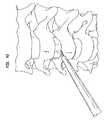
- a chisel guidein order to cut protrusion channels in the endplates, a chisel guide may be utilized.
- the chisel guidepreferably includes a distal head that is insertable into the disc space.
- the distal headpreferably has grooves formed in top and bottom surfaces of the distal head for guiding a chisel for cutting protrusion channels.
- the chisel guidepreferably has alignment openings for sliding over the reference pins.
- the reference pinspreferably align and direct the chisel guide into the disc space. Chisels may then be advanced along the sides of the chisel guide for cutting the protrusion channels.
- a first pair of chisels(e.g., roughening chisels) is advanced along the sides of chisel guide to cut channels.
- the first pair of chiselscuts channels that are approximately 1 mm wide.
- a second pair of larger chiselse.g., finishing chisels
- a first pair of chiselsis approximately 1 mm wide and 1.5 mm high, and a second pair of chisels (e.g., the finishing chisels) are 1.5 mm wide and 2.5 mm high.
- the implantmay be mounted to an insertion tool (e.g., to the distal tip of an insertion tool) and inserted into the disc space.
- the insertion toolpreferably includes upper and lower guide slots or openings that permit the insertion tool to slide along the reference pins.
- the guide slotsare preferably ramped so that the disc space is distracted (to preferably approximately 2 mm wider than the height of the implant) to ensure easy insertion of the implant.
- the reference pinsmay also be engaged by a distraction tool to distract the disc space during insertion, e.g., if such distraction is necessary. This additional distraction may ensure that the device is implanted easily without requiring excessive impacting.
- a tamping instrumentmay be used to adjust the final position of the disc components relative to one another and/or relative to the vertebral bones.
- a proximal feature of the devicee.g., an anterior wall
- an instrumente.g., an extraction instrument
- the surgeonmay introduce a guide, such as a reference pin grill guide, that permits the surgeon to drill guide holes in superior and inferior vertebral bodies (preferably parallel to one another) for the placement of the pair of reference pins.
- a second guidesuch as a sleeve or reference pin driver guide may be used to ensure that the reference pins are placed in the pre-drilled holes so that the pins are parallel, and are driven into the adjacent vertebral bones preferably along the midline of the bones, and at predetermined distances from the endplates.
- the surgeonmay apply distraction to the disc space, e.g., by means of a distraction tool, and then complete the discectomy and distraction.
- the surgeonshould preferably remove any anterior or posterior osteophytes that may interfere with the ultimate placement of the implant.
- features and methods and functionalities of the present inventionincluding but not limited to features and methods and functionalities for engaging one tool (or parts thereof) with one or more other tools (or parts thereof) or with the implants (or parts thereof), and vice-versa; for addressing, avoiding, manipulating, or engaging the patient's anatomy; for aligning one or more tools with anatomic or non-anatomic reference points; and for aligning the tools and implants with one another and/or a treatment space; are not and should not be limited to those embodied in and achieved by the structures and methods of the specific embodiments described and shown, but rather the structures and methods of the specific embodiments described and shown are merely examples of structures and methods that can achieve certain features and methods and functionalities of the present invention.
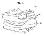
- FIG. 1shows a perspective view of an intervertebral disc implant, in accordance with certain preferred embodiments of the present invention.
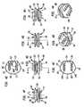
- FIGS. 2A-2Hshow a top element of the intervertebral disc implant shown in FIG. 1 .
- FIGS. 3A-3Hshow a bottom element of the intervertebral disc implant shown in FIG. 1 .
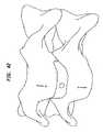
- FIGS. 4A-4Hshow other views of the intervertebral disc implant shown in FIG. 1 .
- FIG. 5shows a perspective view of the top and bottom elements of the intervertebral disc implant shown in FIG. 1 .
- FIG. 6Ashows an anterior end view of the intervertebral disc implant shown in FIG. 1 .
- FIG. 6Bshows a side elevational view of the intervertebral disc implant shown in FIG. 1 .
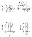
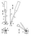
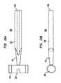
- FIGS. 7A-7Dshow a template, in accordance with certain preferred embodiments of the present invention.
- FIGS. 8A-8Dshow a template marker, in accordance with other preferred embodiments of the present invention.
- FIGS. 9A-9Bshow the template marker of FIG. 8A being attached to a template handle, in accordance with certain preferred embodiments of the present invention.
- FIGS. 10A-10Dshow the template marker and the template handle shown in FIGS. 9A-9B .
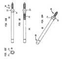
- FIGS. 11A-11Dshow a reference pin drill guide, in accordance with certain preferred embodiments of the present invention.
- FIG. 12shows a drill bit used with the reference pin drill guide shown in FIGS. 11A-11D .
- FIGS. 13A-13Bshow the reference pin drill guide of FIGS. 11A-11D inserted into an intervertebral disc space, in accordance with certain preferred embodiments of the present invention.
- FIGS. 14A-14Cshow a reference pin insertion guide, in accordance with certain preferred embodiments of the present invention.
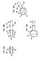
- FIGS. 15A-15Cshow a reference pin, in accordance with certain preferred embodiments of the present invention.
- FIG. 16shows a reference pin, in accordance with another preferred embodiment of the present invention.
- FIGS. 17A-17Cshow a reference pin driver, in accordance with certain preferred embodiments of the present invention.
- FIGS. 18A-18Bshow a sleeve used with the reference pin insertion guide of FIGS. 14A-14C , in accordance with certain preferred embodiments of the present invention.
- FIGS. 19A-19Cshow a distractor, in accordance with certain preferred embodiments of the present invention.
- FIGS. 20A-20Dshow a drill guide, in accordance with certain preferred embodiments of the present invention.
- FIGS. 21A-21Dshow a chisel guide, in accordance with certain preferred embodiments of the present invention.
- FIGS. 22A-22Dshow a chisel used in cooperation with the chisel guide of FIGS. 21A-21D .
- FIG. 23shows the chisel of FIGS. 22A-22D , coupled with the chisel guide of FIGS. 21A-21D .
- FIGS. 24A-24Bshow a mallet, in accordance with certain preferred embodiments of the present invention.
- FIGS. 25A-25Dshow a sizer, in accordance with certain preferred embodiments of the present invention.
- FIGS. 26A-26Eshow the sizer of FIGS. 25A-25D , coupled with a sizer handle, in accordance with certain preferred embodiments of the present invention.
- FIGS. 27A-27Dshow a trial, in accordance with certain preferred embodiments of the present invention.
- FIGS. 28A-28Fshow an implant dispenser, in accordance with certain preferred embodiments of the present invention.
- FIGS. 29A-29Eshow the implant dispenser of FIGS. 28A-28F , coupled with the intervertebral disc implant shown in FIG. 1 .
- FIGS. 30A-30F-1show an inserter head for inserting an intervertebral disc into a disc space, in accordance with certain preferred embodiments of the present invention.
- FIG. 31shows the inserter head of FIG. 30A and an exploded view of an inserter handle, in accordance with certain preferred embodiments of the present invention.
- FIGS. 32A-32Bshow the inserter head and inserter handle of FIG. 31 assembled together.
- FIGS. 33A-33Bshow an intervertebral disc implant being transferred from an implant dispenser to an inserter head, in accordance with certain preferred embodiments of the present invention.
- FIGS. 34A-34Bshow an intervertebral disc implant, coupled with an inserter head, in accordance with certain preferred embodiments of the present invention.
- FIGS. 35A-35Bshow an intervertebral disc implant being disengaged from a distal end of an inserter head, in accordance with certain preferred embodiments of the present invention.
- FIGS. 36A-36Bshow a tamp, in accordance with certain preferred embodiments of the present invention.
- FIGS. 37A-37Dshow an extractor, in accordance with certain preferred embodiments of the present invention.
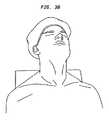
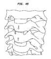
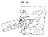
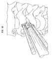
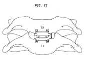
- FIGS. 38-74show a method of inserting an intervertebral disc implant, in accordance with certain preferred embodiments of the present invention.
- FIG. 75Ashows a side view of the intervertebral disc implant shown in FIG. 72 .
- FIG. 75Bshows an anterior end view of the intervertebral disc implant shown in FIG. 73 .
- an intervertebral disc implant 100includes a top element 102 and a bottom element 104 .
- the top and bottom elements 102 , 104have opposing articulating surfaces that engage one another.
- the intervertebral disc implantis adapted to be inserted into a disc space between adjacent vertebrae.
- the top element 102includes a first bone engaging surface 106 having protrusions 108 A, 108 B and a second articulating surface 110 .
- the top elementhas a posterior end 112 and an anterior end 114 .
- the two protrusions 108are interconnected by an anterior wall 116 that extends along the anterior end 114 of the top element.
- the anterior wallpreferably serves as a vertebral body stop to prevent over insertion of the intervertebral disc implant and/or posterior migration of the implant.
- the anterior wall of the top element 102preferably provides an engagement surface to be engaged by instruments, including but not limited to tamps and extraction or repositioning instruments.
- the anterior wallmay have a curved posterior face adapted to sit flush against a curved anterior face of a vertebral body.
- one or more surfaces of the anterior wallmay be coated with an osteoconductive material to facilitate long-term fixation to an endplate surface.
- the articulating surface 110preferably defines a convex curve extending between the sides 118 , 120 of the top element 102 .
- the articulating surface 110also defines a concave curve or surface extending between the posterior and anterior ends 112 , 114 of the top element 102 .
- the articulating surface 110defines a toroidal saddle-shaped surface.
- each protrusion 108preferably has an engagement feature, or depression 121 formed in an outer surface thereof.
- the depressions 121are vertically extending.
- the protrusionsmay have one or more holes extending at least partially or completely therethrough. The holes may receive or be suitable for receiving a bone-growth inducing material.
- the depressions 121facilitate engagement of the top element with instruments, and specifically preferably facilitate securing and handling of the top element 102 during an intervertebral disc insertion operation.
- the depressions 121 on the two protrusions 108are preferably in alignment with one another. In other words, the depressions 121 are preferably at the same distance between the posterior end 112 and the anterior end 114 of the top element 102 .
- each protrusion 108preferably includes teeth 122 having sloping surfaces 124 (e.g., having a low point nearer to the posterior end 112 of the top element 102 and a high point nearer to the anterior end 114 of the top element 102 ) that facilitate insertion of the posterior end 112 of the top element 102 .
- the sloping surfaces 124 of the teeth 122facilitate insertion of the implant in a direction indicated by arrow D 1 .
- the vertical surfaces 126 of the teeth 122hinder or prevent dislodgement of the implant in the direction indicated by arrow D 2 .
- the teeth 122 on protrusions 108preferably also include laterally sloping surfaces 126 that slope downwardly from apexes close to axis A 1 to the lateral sides 118 , 120 of the top element 102 .
- the sloping surfaces 126slope away from axis A 1 .
- the intervertebral disc implantpreferably includes a bottom element 104 having a first bone engaging surface 128 and a second articulating surface 130 that engages the articulating surface 110 of the top element 102 ( FIG. 2A ).
- the bottom element 104includes a posterior end 132 , an anterior end 134 , and lateral sides 136 , 138 .
- the first bone engaging surface 128includes first and second protrusions 140 A, 140 B.
- Each protrusionpreferably has an engagement feature or depression 142 formed in an outer surface thereof. In certain preferred embodiments, the depressions 142 are vertically extending.
- the protrusionsmay have one or more holes extending at least partially or completely therethrough.
- the holesmay receive or be suitable for receiving a bone-growth inducing material.
- the depressions 142facilitate engagement of the bottom element with instruments, and specifically preferably facilitate securing and handling of the bottom element 104 during an intervertebral disc insertion operation.
- the depressions 142 on the two protrusions 140 A, 140 Bare preferably in alignment with one another. In other words, the depressions 142 are preferably at the same distance between the posterior end 132 and the anterior end 134 of the bottom element 104 . Referring to FIGS.
- each protrusion 140 A, 140 Bpreferably also includes teeth 144 having sloping surfaces 146 having a low point nearer to the posterior end 132 of the bottom element 104 and a high point nearer to the anterior end 134 of the bottom element 104 . Similar to the sloping surfaces of the teeth of the top element 102 described above, the sloping surfaces 146 on the teeth 144 facilitate insertion of the bottom element 104 in the direction indicated by arrow D 3 . The vertical surfaces 147 of the teeth 144 hinder or prevent dislodgement of the implant in the direction indicated by arrow D 4 ( FIG. 3 ).
- the teeth 144preferably also include laterally sloping surfaces 148 that slope downwardly toward axis A 2 ( FIG. 3H ). More specifically, the sloping lateral surfaces have apexes or high points closer to the lateral sides 136 , 138 and low points that are closer to axis A 2 .
- the bottom element 108also includes an anterior wall 150 that extends between the protrusions 140 A, 140 B.
- the anterior wallpreferably serves as a vertebral body stop to prevent over insertion of the intervertebral disc and/or posterior migration of the implant.
- the anterior wallpreferably provides an engagement surface that can be engaged by instruments, including but not limited to tamps and extraction or repositioning instruments.
- the anterior wallmay have a curved posterior face adapted to sit flush against a curved anterior face of a vertebral body.
- one or more surfaces of the anterior wallmay be coated with an osteoconductive material to facilitate long-term fixation to an endplate surface.
- the articulating surface 130preferably defines a convex curve or surface extending between the posterior 132 and anterior ends 134 of the bottom element 104 .
- the articulating surface 130preferably defines a concave curve or surface extending between the lateral sides 136 , 138 of the bottom element 104 .
- the articulating surface 130preferably defines a toroidal saddle-shaped surface that engages the articulating surface of the top element 102 ( FIG. 2G ).
- FIGS. 4A and 4Bshow the top element 102 of FIG. 2A being coupled with the bottom element 104 of FIG. 3A .
- each of the top and bottom elements 102 , 104desirably has a respective anterior wall 116 , 150 that extends between protrusions.
- the anterior walls 116 , 150preferably extend along the anterior ends 114 , 134 of the respective top and bottom elements.
- FIG. 4Dshows top element 102 including posterior end 112 , anterior end 114 , and lateral sides 118 , 120 .
- the top element 102includes first bone engaging surface 106 and protrusions 108 A, 108 B having depressions 121 formed in outer surfaces thereof.
- the top element 102includes anterior wall 116 extending between protrusions 108 A, 108 B.
- bottom element 104has a posterior end 132 , anterior end 134 , and lateral sides 136 , 138 .
- the bottom element 104includes bone engaging surface 128 and protrusions 140 A, 140 B.
- the protrusionsinclude depressions 142 formed in outer surfaces thereof.
- the bottom element 104also includes anterior wall 150 extending between protrusions 140 A, 140 B.
- the opposing articulating surfaces 110 , 130 of the top element 102 and the bottom element 104are adapted to engage one another.
- the teeth 122 on the top element 102slope downwardly toward the posterior end 112 thereof.
- the teeth 144 on the bottom element 104slope downwardly toward the posterior end 132 thereof.
- the teeth 122 on the top element 102have lateral sloping surfaces 126 that slope downwardly toward the sides 118 , 120 .
- the teeth 144 on the bottom element 104include lateral sloping surfaces 148 that slope inwardly toward axis A 3 ( FIG. 4F ).
- the lateral sloping surfaces 126 of the teeth 122 on the top element 102slope in a different direction than the lateral sloping surfaces 148 of the teeth 144 on the bottom element 104 .
- the apex of the teeth 122 on the top element 102is closer to axis A 3 than the apex of the teeth 144 on the bottom element 104 .
- the present inventionseeks to avoid this cracking problem by offsetting the apexes of the teeth on the top element 102 from the apexes of the teeth on the bottom element 104 .
- the present inventionis not limited by any particular theory of operation, it is believed that providing teeth having off-set apexes enables two or more intervertebral disc implants to be inserted into two or more successive disc spaces, while minimizing the likelihood of cracking the vertebral bodies between the disc spaces.
- the articulating surface 110 of the top element 102opposes the articulating surface 130 of the bottom element 104 .
- the articulating surface 110 of the top element 102defines a toroidal saddle-shaped surface including a concave surface extending between proximal and anterior ends thereof and a convex surface extending between the sides of the top element 102 .
- the articulating surface 130 of the bottom element 104also includes a toroidal saddle-shaped surface having a convex surface extending between the posterior and anterior ends and a concave surface extending between the sides of the bottom element 104 .
- the longitudinally inwardly directed articulation surface of the top element 102forms a constant radii saddle-shaped articulation surface.
- the saddle surfaceis defined by a concave arc that is swept perpendicular to and along a convex arc.
- the articulation surfacehas a cross-section in one plane that forms a concave arc, and a cross-section in another plane (perpendicular to that plane) that forms a convex arc.
- the concave archas a respective constant radius of curvature about an axis perpendicular to the one plane.
- the convex archas a respective constant radius of curvature about an axis perpendicular to the other plane.
- the concave archas a constant radius of curvature A about an axis perpendicular to the anterior-posterior plane, and the convex arc has a constant radius of curvature B about an axis perpendicular to the lateral plane.
- radius Ais less than radius B.
- the longitudinally inwardly directed articulation surface of the bottom element 104also preferably forms a constant radii saddle-shaped articulation surface. More particularly, the saddle surface is defined by a convex arc that is swept perpendicular to and along a concave arc.
- the articulation surfacehas a cross-section in one plane that forms a convex arc, and a cross-section in another plane (perpendicular to that plane) that forms a concave arc.
- the convex archas a respective constant radius of curvature about an axis perpendicular to the one plane.
- the concave archas a respective constant radius of curvature about an axis perpendicular to the other plane.
- the convex archas a constant radius of curvature C about an axis perpendicular to the anterior-posterior plane, and the concave arc has a constant radius of curvature D about an axis perpendicular to the lateral plane.
- radius Cis less than radius D.
- the constant radii saddle shaped articulation surfacesare configured and sized to be nestable against one another and articulatable against one another, to enable adjacent vertebral bones (against which the top and bottom elements are respectively disposed in the intervertebral space) to articulate in flexion, extension, and lateral bending.
- the intervertebral disc of the present inventionis assembled by disposing the top and bottom elements so that the vertebral body contact surfaces are directed away from one another, and the articulation surfaces are nested against one another such that the concave arcs accommodate the convex arcs.
- the concave arcs of the top element 102ride on the convex arcs of the bottom element 104 about a center of rotation below the articulation surfaces.
- the concave arcs of the bottom element 104ride on the convex arcs of the top element 102 about a center of rotation above the articulation surfaces.
- the elementsare maintained at constant relative distraction positions, i.e., the elements do not move in directions that are directed away from one another (for example, do not move in opposing axial directions from one another (e.g., along a longitudinal axis of the spine)).
- the present inventionprovides a pair of articulation surfaces that have a center of rotation above the surfaces in one mode of motion (e.g., lateral bending), and below the surfaces in another (e.g., flexion/extension), consistent in these regards with a natural cervical intervertebral joint.
- the articulation surfacesare sized and configured so that the respective ranges of angles through which flexion/extension and lateral bending can be experienced are equal to or greater than the respective normal physiologic ranges for such movements in the cervical spine.
- the adjacent vertebral bonesbe permitted by the intervertebral disc implant to axially rotate relative to one another (e.g., about the longitudinal axis of the spinal column) through a small range of angles without moving in opposite (or otherwise directed away from one another) directions (e.g., along the longitudinal axis) within that range, and then to engage in such opposite (or otherwise directed away from one another) movement once that range is exceeded.
- the articulation surfacesare accordingly configured and sized to permit such movements.
- the top and bottom elementsare able to axially rotate relative to one another about the longitudinal axis of the spinal column through a range of angles without causing the vertebral body contact surfaces to move away from one another along the longitudinal axis. Once the axial rotation exceeds that range, the articulation surfaces interfere with one another as the concave arcs move toward positions in which they would be parallel to one another, and the distance between the vertebral body contact surfaces increases with continued axial rotation as the concave arcs ride up against their oppositely directed slopes.
- the articulation surfacesare configurable according to the present invention to permit normal physiologic axial rotational motion of the adjacent vertebral bones about the longitudinal axis through a range of angles without abnormal immediate axially opposite (or otherwise directed away from one another) movement, and to permit such axially opposite (or otherwise directed away from one another) movement when under normal physiologic conditions it should occur, that is, outside that range of angles.
- the articulation surfacespreferably maintain contact over a range of normal physiologic articulating movement between the adjacent vertebral bones. That is, through flexion, extension, lateral bending, and axial rotation, the articulation surfaces are in contact with one another.
- the surface area dimensions of the articulation surfacesare selected in view of the selected radii of curvature to prevent the edges of the saddle surfaces (particularly the edges of the concave arcs) from hitting any surrounding anatomic structures, or other portions of the opposing upper or lower element, before the limit of the normal physiologic range of an attempted articulation is reached.
- FIGS. 6A and 6Bshow, according to a preferred embodiment of the present invention, an intervertebral disc implant 100 including top element 102 and bottom element 104 .
- the articulating surface of the top element 102preferably engages the articulating surface of the bottom element 104 .
- the articulating surface of the top element 102preferably defines a convex surface extending between lateral sides 118 , 120 thereof.
- the articulating surface of the bottom element 104defines a concave surface extending between the lateral sides 136 , 138 thereof.
- Each of the top and bottom elements 102 , 104include respective anterior walls 116 , 150 that prevent over insertion and/or posterior migration of the intervertebral disc implant 100 .
- the teeth 122 on the protrusions of the top element 102include laterally sloping surfaces 124 that slope downwardly toward the sides 118 , 120 .
- the teeth 144 on the protrusions of the bottom element 104include laterally sloping surfaces 148 that preferably slope downwardly toward a central region of the bottom element 104 .
- the opposite sloping configuration of the teeth on the respective top and bottom elements 102 , 104preferably permits stacking of two intervertebral disc implants in two successive disc spaces, while minimizing the likelihood of cracking the vertebral bone between the adjacent disc spaces.
- the opposite sloping configuration of the teethenable three or more intervertebral discs to be stacked atop one another over three or more successive disc spaces.
- the teeth of the top and bottom elementsmay slope laterally in the same direction.
- the articulating surface of the top element 102defines a concave surface extending between posterior 112 and anterior 114 ends thereof.
- the articulating surface of the bottom element 104defines a convex surface extending between the posterior 132 and anterior 134 ends of the bottom element 104 .
- the teeth 122 on the protrusions of the top element 102include sloping surfaces 124 that slope downwardly toward the posterior end 112 of the top element 102 .
- the teeth 144 on the protrusions of the bottom element 104have sloping surfaces 146 that slope downwardly toward the posterior end 132 of the bottom element 104 .
- the sloping surfaces 124 , 146 of the respective teeth 122 , 144slope in the same direction, i.e., toward the posterior ends of the top and bottom elements 102 , 104 .
- the respective sloping surfaces 124 , 146facilitate insertion of the implant 100 into a disc space.
- the respective vertical surfaces 122 , 144hinder or prevent expulsion or migration of the implant from the disc space after it has been inserted.
- a template 154has a distal end 156 and a proximal end 158 .
- the template 154includes a shaft 160 extending between the distal and proximal ends and a handle 162 secured to a proximal end of the shaft.
- the templateincludes a template marker 164 .
- the template marker 164has a cruciform-like structure with a first vertically extending arm 166 , a second vertically extending arm 168 , a first lateral arm 170 and a second lateral arm 172 .
- the upper and lower ends of the respective first and second vertically extending arms 166 , 168preferably have apexes that may be used for aligning scoring of the anterior faces of the adjacent vertebral bodies.
- the score marksmay later be used for aligning other tools and/or the intervertebral disc.
- the template marker 164includes a central pin 174 , a first tack 176 on the first vertical arm 166 and a second tack 178 on the second vertical arm 168 .
- the central pin 174is adapted to engage a natural disc and the tacks 176 , 178 are adapted to engage bone, such as vertebral bone.
- the central pin 174may also be replaced or supplanted by a plurality of pins positioned on the lateral arms 170 , 172 .
- the lateral arms 170 , 172preferably define a distal surface 180 that is curved for matching the curve of the anterior surface of a natural intervertebral disc.
- FIGS. 8A-8Dshow a template marker for a template, in accordance with another preferred embodiment of the present invention.
- the template marker 164 ′is substantially similar to the template marker shown in FIG. 7D .
- the template marker 164 ′ shown in FIGS. 8A-8Dincludes first and second engagement features or projections 182 A′ and 182 B′ projecting from top and bottom surfaces of adapter shaft 184 ′.
- the template marker 164 ′may be attached to a distal end 156 ′ of a template handle 162 ′.
- the adapter shaft 184 ′ of the template marker 164 ′is inserted into an opening at the distal end 156 ′ of the template handle 162 ′.
- the projections 182 A′, 182 B′ on the adapter shaft 184 ′are inserted into opposing grooves 186 ′ formed in the template handle 162 ′.
- FIGS. 10A-10Bshow the template marker 164 ′ secured to the distal end 156 ′ of the template handle 162 ′.
- a rotatable handle 188 ′is rotated for advancing shaft 190 ′ relative to outer shaft 192 ′ so as to lock the template marker 164 ′ to the distal end 156 ′ of the template handle 162 ′.
- the template handle 162 ′is rotated to seat the projections 182 A′, 182 B′ in the grooves 186 ′ and the rotatable handle 188 ′ is rotated to hold the projections 182 A′, 182 B′ forward in the grooves 186 ′.
- FIGS. 11A-11Bshow a reference pin drill guide 194 having a distal end 196 , a proximal end 198 , a shaft 200 extending between the distal and proximal ends and a handle 202 at the proximal end of the shaft 200 .
- the distal end 196 of the reference pin drill guideincludes a main body 204 having an upper end 206 and a lower end 208 .
- the main bodyincludes a first opening 210 extending therethrough adjacent upper end 206 and a second opening 212 extending therethrough adjacent lower end 208 .
- the main bodyincludes a head 214 that projects from a distal side thereof.
- the headincludes a tapered nose 216 , a top surface 218 , and a bottom surface 220 .
- the head 214also includes a first vertebral body stop 222 projecting upwardly from top surface 218 and a second vertebral body stop 224 projecting below second surface 220 .
- the shaft 200 of the reference pin drill guide 194is preferably angled or curved so that the working end of the tool may be observed by a surgeon.
- a distal end 226 of a drill bit 228may be passed through openings 210 , 212 for forming holes in the vertebral bone.
- the threaded ends of reference pinsmay be inserted into the holes.
- the main body 204preferably includes an upper alignment flange 230 projecting from upper end 206 thereof and a lower alignment flange 232 projecting from lower end 208 of main body 204 , for use in aligning the flanges with alignment marks previously scored on the vertebral bones.
- the drill bit 228includes a distal end 226 and a proximal end 234 adapted to be secured by a drill.
- the drill bit 228includes a shoulder 236 that limits advancement of the drill bit through the openings 210 , 212 of the main body 204 .
- the head 214 of the reference pin drill guide 194is inserted into the disc space between the vertebral bodies.
- the headis advanced until the vertebral body stops abut the anterior faces of the respective vertebral bodies.
- the distal end of the drill bit 228is then inserted through the openings 210 , 212 in the main body 204 .
- the distal end of the drill bit 228is advanced into bone to form the openings for the reference pins.
- a reference pin insertion guide 236has a distal end 238 , a proximal end 240 , a shaft 242 extending between the distal and proximal ends and a handle 244 secured to the distal end of the shaft 242 .
- the reference pin insertion guide 236includes alignment guide body 246 having an upper end including a first opening 248 and a lower end including a second opening 250 .
- the distal endalso includes a head 252 insertable into an intervertebral disc space.
- the head 252has a tapered nose 254 , a top surface 256 terminating at a first vertebral body stop 258 and a bottom surface 260 terminating at a second vertebral body stop 262 .
- the first and second vertebral body stops 258 , 262preferably prevent over insertion of the tool into an intervertebral disc space.
- FIGS. 15A-15Cshow an alignment or reference pin 264 , in accordance with certain preferred embodiments of the present invention.
- the reference pin 264has a distal end 266 and a proximal end 268 .
- the distal end 266includes a threaded portion 270 that is threadable into vertebral bone.
- the distal end of reference pin 264also preferably includes a flange 272 that limits insertion of the reference pin.
- a proximal side of the flange 272includes a feature or hex nut 274 engageable by a driver.
- FIG. 16shows a rescue reference pin 264 ′, in accordance with another preferred embodiment of the present invention.
- the rescue pin 264 ′is substantially similar to the reference pin 264 shown in FIG. 15B and includes a threaded shaft 276 ′ located on a posterior side of flange 272 ′.
- the rescue pin 264 ′is preferably used if the reference pin 264 shown in FIG. 15B does not remain anchored to bone or pulls out of the bone.
- the rescue pin 264 ′preferably has larger diameter threading (than the reference pin 264 ) at the leading end thereof.
- a reference pin driver 280is utilized for driving reference pins into bone.
- the reference pin driver 280includes a distal end 282 having an opening adapted to receive a reference pin 264 (or a rescue pin 264 ′) and a proximal end 284 including a handle 286 .
- the reference pin driver 280also includes a shaft 288 that extends between the distal end 282 and the proximal end 284 .
- the shaft 288preferably has an opening including at least one hexagonal surface that matches the hexagonal nut 274 on the reference pin 264 ( FIG. 15A ).
- FIGS. 18A and 18Bshow, for use in preferred embodiments of the invention, a sleeve 290 insertable into the openings in the reference pin drill guide 194 .
- the sleeve 290includes a distal end 292 having an opening 294 and a proximal end 296 including a stop flange 298 .
- the distal end 292 of sleeve 290includes opening 294 extending therethrough and larger opening 296 at the distal-most end.
- the enlarged opening 296preferably has a circular counterbore that freely slides over the hex nut on the reference pin 264 described above.
- the smaller opening 294preferably forms a sliding fit with an outer surface of the reference pin 264 .
- the sleeve 290preferably stabilizes the reference pin insertion guide 236 after the first reference pin has been inserted into bone and during insertion of the second reference pin.
- FIGS. 19A-19Cshows a distraction instrument 300 including support element 302 and first and second distracting arms 304 , 306 that travel over the support element 302 .
- Each distracting arm 304 , 306has a curved section 308 and openings 310 at distal ends of the arms 304 , 306 .
- the distracting element 300also includes adjustment element 312 that interacts with support body 302 and arms 304 , 306 for adjusting the distance between the arms.
- the distractor arms 304 , 306are slid over the reference pins.
- the adjusting element 312may be operated for separating the distractor arms 304 , 305 so as to distract adjacent vertebrae and allow for removal of disc material.
- a drill guide 314has a distal end 316 , a proximal end 318 , a shaft 320 extending between the distal and proximal ends and a handle 322 adjacent the distal end 318 .
- the drill guideincludes a main body 324 attached to the distal end of the shaft 320 .
- the main body 324includes first and second openings 326 , 328 for engaging the reference pins.
- the main body 324also includes four drill guide openings 330 A- 330 D for guiding a distal end 332 of a drill bit 334 .
- the four drill guide openings 330 A- 330 Dare positioned to coincide with the protrusions of an intervertebral disc implant.
- the main body 324also includes a head 336 insertable into an intervertebral disc space.
- the head 336includes a tapered nose 338 , a top surface 340 , a bottom surface 342 , and first and second vertebral body stops 344 , 346 extending above and below the top and bottom surfaces 340 , 342 .
- the alignment openings 326 , 328are slid over the reference pins and the tool is advanced until the head 336 is positioned in the intervertebral disc space.
- the distal end 332 of the drill bit 334is then passed in series through the drill alignment openings 330 A- 330 D for at least partially forming protrusion openings for the protrusions of an intervertebral disc implant.
- a chisel guide 350includes a distal end 352 , a proximal end 354 with a handle 356 and a shaft 360 extending from the proximal end toward the distal end.
- the shaft 360includes on one side a left track 362 having an opening 364 at the proximal end 354 and extending toward the distal end 352 , and, on an opposite site, a right track 362 ′ having an opening 364 ′ at the proximal end 354 and extending toward the distal end 352 .
- the chisel guide 350includes a head 366 at the distal end 352 . Referring to FIGS. 21C and 21D , the head 366 includes alignment grooves 368 formed in top and bottom surfaces thereof. The alignment grooves are adjacent the left and right tracks of the shaft 360 .
- the chisel guidealso includes first and second reference pins openings 370 , 372 .
- the reference pin openings 370 , 372are slid over the reference pins described above, and the head 366 is inserted into an intervertebral disc space.
- a chisel 374has a distal end 376 with first and second cutting blades 378 , 380 , and a proximal end 382 having a handle 384 and a striking surface 386 .
- the chisel 374includes a shaft 388 extending between the distal and proximal ends of the tool.
- the shaft 388includes projections extending therefrom for guiding the chisel in the tracks of the chisel guide shown in FIGS. 21A-21D .
- the projections 390guide the chisel along the track while maintaining alignment of the chisel.
- the distal end of the chiselincludes an opening extending between cutting blades 378 , 380 .
- the opening 394allows the cutting blades 378 , 380 to slide over the grooves 368 formed in the top and bottom surfaces of the head 366 ( FIG. 21D ).
- the chisel guide 350 described in FIGS. 21A-21Dis slid over the reference pins 264 secured to bone.
- the chisel 374 of FIGS. 22A-22Dis then slideably advanced along one of the tracks of the chisel guide for forming protrusion openings in the bone.
- the same or a second chisel 374is then slideably advanced along the other of the tracks to form additional protrusion openings in the bone.
- FIGS. 24A-24Bshow a mallet 396 including a handle 398 having a lower end 400 and an upper end 402 with a striking element 404 secured to the upper end.
- the striking element 404includes a U-shaped opening 406 formed therein so that the mallet may be used as a slap hammer.
- FIGS. 25A-25Dshow a sizer 408 , in accordance with certain preferred embodiments of the present invention.
- the sizer 408includes a main body 410 having a distal end 412 , a top surface 414 , and a bottom surface 416 .
- the body 410includes sloping surfaces 418 extending between the distal end 412 and the top and bottom surfaces 414 , 416 to ease insertion of the sizer between the vertebrae.
- the sizer 408also includes an adapter shaft 420 and first and second projections 422 A, 422 B.
- the sizeralso includes vertebral body stops 424 and 426 for limiting insertion of the sizer.
- the sizersare preferably provided in variable heights (e.g., 5-9 mm) and variable base plate widths (e.g., 14 and 16 mm) Sequentially larger sizers are used to determine the desired implant height that will best fit into the disc space without over-tensioning the annulus. In their preferred usage, the sizer that fits snugly into the disc space with mild to moderate resistance to pull-out should indicate the proper height of the disc to be implanted.
- a sizer 408may be attached to a distal end 430 of a handle 432 by sliding the projections 422 A, 422 B into grooves extending from the distal end 430 of the handle 432 .
- a rotatable element 434may be rotated for locking the sizer 408 to the handle 432 .
- the handle 432is rotated to seat the projections 422 A, 422 B in the grooves extending from the distal end 430 of the handle and the rotatable element 434 is rotated to hold the projections 422 A, 422 B forward in the closed ends of the grooves.
- a trial 436includes a distal end 438 , a proximal end 440 , a shaft 442 extending between the distal and proximal ends, and a striking surface 444 located at the proximal end 440 of the shaft 442 .
- the trialalso includes a trial implant 446 secured at distal end 438 .
- the trial implant 446includes protrusions 448 having teeth 450 that are positioned to coincide with the protrusions of a intervertebral implant.
- the size of the trial implant 446is selected based upon the largest sizer that safely fit within the intervertebral disc space.
- the trial 436also includes reference pin alignment openings 452 , 454 .
- the reference pin alignment openings 452 , 454are adapted to slide over the reference pins secured to vertebral bone.
- an implant dispenser 456is adapted to hold the top and bottom elements of an intervertebral disc implant as a single unit with the articulating surfaces held together.
- the implant dispenser 456is preferably flexible and includes a superior arm 458 for engaging a top element of an intervertebral disc implant and an inferior arm 460 for engaging a bottom element of an intervertebral disc implant.
- the superior and inferior armspreferably have lateral notches 462 formed therein for receiving the teeth of the top and bottom elements, as will be described in more detail herein.
- the implant dispenseralso preferably includes a central support 464 that enables the superior and inferior arms 458 , 460 to move away from one another for releasing an intervertebral disc implant.
- the superior arm 458preferably has indicia such as a text or a symbol 466 indicating that the arm 458 overlies the top element of the implant.
- the indicia on the superior armmay also preferably include the size 468 of the implant.
- FIG. 28Fshows the inferior arm 460 including indicia such as a text or a symbol 470 indicating that the arm 460 overlies the bottom element of the implant.
- the inferior element indiciamay also include size information 472 as shown.
- FIGS. 29A-29Eshow the intervertebral disc implant of FIG. 1 secured in the implant dispenser 456 of FIGS. 28A-28F .
- the intervertebral disc implantincludes top element 102 engaged by superior arm 458 and central element 464 .
- the bottom element 104is engaged by inferior arm 460 and central element 464 .
- the teeth of the implantextend through the notches 462 in the superior and inferior arms.
- FIGS. 30A to 30E-1show an inserter head for inserting an intervertebral disc implant.
- the inserter head 474includes a main body 476 having a distal end 478 and a proximal end 480 .
- the distal end 478 of the main body 476includes four spaced arms 482 having inwardly facing surfaces with projections 484 that are adapted to fit within the depressions formed within the protrusions of the top and bottom elements of the intervertebral disc implant.
- the main bodyincludes a central opening 486 extending from the proximal end 480 to the distal end 478 thereof. Referring to FIGS.
- the main body 476also includes an upper alignment groove 488 and a lower alignment groove 490 .
- the alignment grooves 488 , 490are adapted to engage the reference pins for guiding advancement of the inserter head.
- the alignment grooves 488 , 490taper toward one another so that the grooves are closer to one another at distal ends thereof and farther away from one another at proximal ends thereof.
- FIGS. 30E and 30E-1show the projection 484 on one of the four arms 482 .
- the projections 484 on the arms 482engage the depressions in the protrusions of the top and bottom elements of the intervertebral discs.
- FIG. 31shows the inserter head 474 of FIG. 30A prior to assembly with an inserter handle 492 .
- the inserter handle 492includes a pusher rod 494 that may be advanced by a rotatable handle 496 coupled with the pusher rod 494 .
- the handleincludes a shaft 496 that is insertable into opening 486 of the inserter head.
- the element 496may be rotated for advancing the pusher rod 494 . As will be described in more detail below, advancing the pusher rod 494 will disengage the top and bottom elements of an intervertebral disc with the arms 482 of the inserter head 474 .
- FIGS. 33A and 33Bshow the implant dispenser 456 of FIG. 29A holding an intervertebral disc implant 100 .
- the depressions in the protrusionsare coupled with the projections in the arms 482 of the inserter head 474 .
- the implant dispensermay be removed.
- the implant 100is held by the arms 482 of the inserter head.
- the pusher rod 494may be advanced toward the distal end of the inserter head 474 for decoupling the implant 100 from the inserter head 474 .
- a tamp 500includes a distal end 502 , a proximal end 504 , a shaft 506 extending between the distal and proximal ends and a handle 508 adjacent the proximal end 504 .
- the distal end 502includes an abutting surface 510 that is adapted to engage the anterior end of an intervertebral disc implant.
- the tamp 500also includes a striking surface 512 at the proximal end. A device such as the mallet shown and described above may be impacted against the striking surface 512 for applying force to the striking surface 510 of the tamp.
- FIGS. 37A-37Dshow an extractor 514 , in accordance with certain preferred embodiments of the present invention.
- the extractor 514includes a distal end 516 having a hook 518 , a proximal end 520 , and a shaft 522 extending between the distal and proximal ends.
- the extractor 514also preferably includes a handle 524 adjacent the proximal end 520 thereof.
- FIGS. 37C and 37Dshow shaft 522 with a hook 518 at a distal end of the shaft.
- implants, surgical instruments and proceduresin accordance with certain preferred embodiments of the present invention. It is contemplated, however, that the implants, instruments and procedures may be slightly modified, and/or used in whole or in part and with or without other instruments and procedures, and still fall within the scope of the present invention. Although the present invention may discuss a series of steps in a procedure, the steps may be accomplished in a different order, or may be used individually, or in conjunction with other methods, without deviating from the scope of the present invention.
- a review of X-rays, MRI or CT-myelogramis preferably conducted to assess the level to be treated for osteophytes and to compare the intervertebral disc height with the adjacent levels.
- the patientis preferably positioned in the supine position to provide for an anterior surgical approach to the cervical spine. Steps should preferably be taken to stabilize the patient's spine in a neutral position and to prevent rotation during the procedure. In certain preferred embodiments, it may be preferable to place a towel or bean bag underneath the patient's shoulders. Tape, a halter or skeletal traction may be used to prevent rotation.
- a transverse skin incisionis preferably made at the appropriate level to expose the targeted spinal segment including the discs above and below the target spinal segment. Care should be taken to avoid prolonged retraction pressure on vital structures, such as the esophagus.
- a templatesuch as the template shown and described above in FIGS. 7A-10D , is utilized to mark the midline.
- the size and dimensions of the templatemay vary. The exact template selected may be based upon initial estimation of the appropriate implant size from pre-operative X-rays and/or MRI/CT.
- the templateis preferably attached to the template handle, as described above in reference to FIGS. 9A-9B and 10A-10D .
- the templatemay have different sizes whereby the lateral arms of the template attachments approximate the width options of the implant (i.e., 14 mm and 16 mm) Referring to FIG. 40 and FIG.
- the central pin at the distal end of the templateis inserted into the middle of the disc so that the upper and lower vertically extending arms are approximately aligned with the midline axis of the vertebral column.
- the tacks on the upper and lower vertical armsengage the vertebral bone to stabilize the template.
- the handle at the proximal end of the template handlemay be tapped, such as by using a mallet, to push the tacks into the vertebral bone.
- the template handlemay then be disengaged from the template, which remains attached to the vertebral bone.
- fluoroscopymay be used to verify the midline and lateral margins of the disc space.
- the spinous processesare preferably centered.
- a toolsuch as a scalpel or an electrocautery tool is preferably utilized to score the midline points on the anterior surfaces of the superior and inferior vertebral bodies. Care is preferably taken to ensure that the midline is well defined for all subsequent endplate preparation and implant insertion steps.
- the template handlemay be reattached to the template for removing the template from engagement with the target area.
- FIG. 42shows the target area of the spine with an opening formed in the disc space by the central pin of the template, and two smaller openings being formed in the respective superior and inferior vertebral bodies by the tacks of the template.
- the scoring of the midline pointsis evident at the anterior surfaces of the superior and inferior vertebral bodies.
- a cutting toolsuch as a scalpel may be used to dissect a window in the annulus of the targeted disc.
- the size of the window dissected in the annuluspreferably approximates the width of an intervertebral disc implant to be inserted therein.
- radiographic imagingsuch as fluoroscopy may be used to identify osteophytes that extend anteriorly. Any osteophytes that extend anteriorly are preferably resected back to the vertebral body so that the surfaces of the superior and inferior vertebral bodies are flattened.
- techniquessuch as radiographic imaging should be used to identify any osteophytes extending downwardly or upwardly into the anterior region of the disc space. Such osteophytes should be resected to the endplates.
- FIG. 44shows the targeted disc space after the initial discectomy has been completed including resection of any anterior osteophytes present in the targeted disc area.
- reference pinsmay be attached to the anterior faces of the superior and inferior vertebral bodies.
- the midline score marks and the tack openings in the superior and inferior vertebral bodiesare preferably used for proper placement of the reference pins. Care is preferably taken to ensure proper placement and alignment of the reference pins, which will guide subsequent steps of the procedure.
- the reference pin drill guide described in FIGS. 11A-11Dis inserted into the dissected disc space. Specifically, the head at the distal end of the reference pin drill guide is inserted into the disc space between the vertebral bodies.
- the head at the distal endis inserted until the vertebral body stops abut against the anterior faces of the superior and inferior vertebral bodies.
- one of the openings in the main body of the reference pin drill guideis preferably in alignment with the superior vertebral body and another one of the openings is in alignment with the inferior vertebral body.
- the reference pin drill guideis preferably aligned with the midline of the vertebral bodies as marked by the score line markings.
- the alignment of the reference pin drill guideis preferably checked such as by using fluoroscopy. Referring to FIG. 46 , with the reference pin drill guide in place, holes are drilled in the superior and inferior vertebral bodies using a drill bit, such as the drill bit shown in FIG. 12 above.
- FIG. 46shows a hole being drilled in the superior vertebral body.
- FIG. 47shows a hole being drilled in the inferior vertebral body.
- FIG. 48shows the target spinal segment after holes have been drilled in both the superior and inferior vertebral bodies.
- the reference pin drill guideis removed from the targeted disc segment.
- a first hole for a first reference pinhas been formed in the superior vertebral body and a second hole for a second reference pin has been formed in the inferior vertebral body.
- the first and second holes in the vertebral bodiesare preferably in alignment with the score marks formed previously.
- the reference pinsmay be inserted using the reference pin insertion guide shown and described above in FIGS. 14A-14C .
- the head at the distal end of the reference pin insertion guideis inserted into the disc space until the vertebral body stops abut against the anterior surfaces of the superior and inferior vertebral bodies.
- the reference pin insertion guidepreferably has a first opening in alignment with the opening formed in the superior vertebral body and a second opening aligned with the opening formed in the inferior vertebral body.
- a reference pin, such as the reference pin shown and described above in FIGS. 15A-15Cis inserted into the first opening of the reference pin insertion guide.
- the threading at the distal end of the reference pinis threaded into the opening in the superior vertebral body.
- the reference pin driver shown in FIG. 17A-17Cmay be utilized for threading the reference pin into the vertebral body.
- the threads on the reference pinsmay be self-tapping threads.
- the second reference pinis passed through the lower opening in the reference pin insertion guide and driven into the inferior vertebral body using the reference pin driver.
- a first reference pinmay be attached to the inferior vertebral body before attaching a second reference pin to the superior vertebral body.
- the insertion of the reference pinscan be accomplished in any particular order.
- a sleevesuch as the sleeve shown and described in FIGS. 18A-18B may be slid over the attached reference pin so as to stabilize the reference pin insertion guide.
- the sleevepreferably remains in place to prevent movement of the reference pin insertion guide during insertion of the second reference pin into the other vertebral body.
- different sized reference pinsmay be used. These different sized reference pins may include shafts having different diameters and/or lengths.
- a small and a large set of reference pinsis provided in an instrument tray. The smaller of the pair of reference pins should be inserted initially. If the smaller pair of reference pins proves unsatisfactory, the larger pair of reference pins may be utilized. As shown in FIG. 53 , the reference pins are preferably parallel to each other and in alignment with the midline of the superior and inferior vertebral bodies.
- a surgeonmay preferably apply distraction to the disc space by using a distraction tool, such as a distractor as shown and described in FIGS. 19A-19C .
- a distraction toolsuch as a distractor as shown and described in FIGS. 19A-19C .
- the disc spacemay be cleared of any extraneous matter and restored to a desired height.
- the facets of the targeted spinal segmentshould be reviewed under fluoroscopy in order to monitor facet orientation during distraction.
- the distractor shown in FIGS. 19A-19Cis preferably placed over the reference pin shown in FIG. 53 .
- FIG. 54shows the distractor after it has been placed over the reference pins. If the reference pins loosen at any time during the distraction procedure, the reference pins may be removed and replaced with the larger reference pins provided in the instrument set.
- the distractoris then utilized to apply distraction to the targeted spinal segment.
- the facets and the disc spaceare preferably monitored under fluoroscopy to ensure a complete distraction.
- the amount of distractionshould not exceed the height of the adjacent disc space.
- fluoroscopyshould be used to monitor the distraction height so as to prevent over-distraction.
- over-distractionmay cause nerve and/or facet damage.
- the discectomy procedureis completed.
- the posterior and lateral margins of the disc spaceare cleared of any extraneous matter.
- the clearing of the posterior and lateral marginspreferably extends to the uncinate processes and all the way back to the nerve root and canal.
- lateral fluoroscopyis utilized to check the anterior aspects of the vertebral body for osteophytes.
- a cutting toolsuch as a burr, may be used to further prepare the endplates of the opposing superior and inferior vertebral bodies.
- the cutting toolmay be utilized to smooth out the curvature of the superior endplate.
- the endplates of the adjacent vertebral bodiesare preferably parallel to one another and relatively uniform, thereby preventing undersizing of the implant.
- the decompression of the targeted disc spacemay be completed by removing any posterior osteophytes or soft tissue material that may inhibit the full distraction of the posterior portion of the targeted disc space.
- the posteriolateral corners of the endplatesmay be resected as needed to provide neural decompression.
- the lateral uncovertebral jointsare preferably not removed unless they are causing nerve root compression.
- it may be necessary to perform a foraminotomyif there are symptoms of neural/foraminal stenosis.
- another stage of the intervertebral disc implantation methodinvolves initial endplate preparation including drilling pilot grooves in the superior and inferior vertebral bodies.
- the distractor shown in FIG. 54is removed.
- the protrusion drill guide of FIGS. 20A-20Dis inserted into the prepared disc space.
- the openings at the upper and lower ends of the drill guideare aligned with the proximal ends of the reference pins.
- the reference pinsengage the openings for guiding the drill guide toward the prepared disc space.
- the head at the distal end of the drill guideis inserted into the prepared disc space until the vertebral body stops abut against the anterior faces of the superior and inferior vertebral bodies.
- the surgeonshould visually check that the vertebral body stops of the drill guide come into full contact with the superior and inferior vertebral bodies.
- the handle of the drill guideis preferably parallel with the inferior and superior endplates and aligned in the sagittal plane.
- a drill bitis utilized to drill four pilot holes for the implant protrusions at precise locations in the vertebral bodies.
- the drill guideincludes two openings for drilling a pair of pilot holes in the superior vertebral body and two openings for drilling pilot holes in the inferior vertebral body.
- the drillincludes a stop to limit the length of the pilot holes. In particular preferred embodiments, there is a stop on the drill so as to ensure that the pilot holes are no more than 10 mm in length.
- the drill guideis retracted from the targeted disc space and decoupled from the two reference pins.
- two pilot holesare formed in the superior vertebral body and two pilot holes are formed in the inferior vertebral body.
- the two pilot holes on the left of the adjacent vertebral bodiesare preferably in vertical alignment with one another and the two pilot holes on the right of the vertebral bodies are preferably in vertical alignment with one another.
- channels for the protrusions of the intervertebral disc implantare formed in the endplates of the superior and inferior vertebral bodies.
- the chisel guide shown and described in FIGS. 21A-21Dis inserted into the targeted disc space.
- the alignment openings in the chisel guideare slid over the reference pins.
- the head at the distal end of the chisel guideis inserted into the targeted disc space until the vertebral body stops come into contact with the anterior surfaces of the vertebral bodies.
- the handle of the chisel guideis preferably parallel with the superior and inferior endplates and aligned in the sagittal plane. As shown in FIG.
- the chisel described in FIGS. 22A-22Dis coupled with one of the tracks of the chisel guide and advanced toward the disc space.
- the cutting blades of the chiselare preferably advanced toward the superior and inferior vertebral bodies while positive pressure is applied to the chisel guide to ensure that it does not back out of the disc space.
- FIG. 23shows the chisel 374 coupled with the chisel guide 350 with the cutting blades at the distal end of the chisel opposing the superior and inferior vertebral bodies.
- a striking instrumentsuch as the mallet shown and described in FIGS. 24A-24B , may be utilized to strike the distal end of the chisel so as to cut channels in the superior and inferior vertebral bodies.
- a second chiselis preferably utilized in the same manner as described above with respect to the first chisel to cut a second set of channels in the vertebral bodies.
- FIG. 59shows the targeted spinal segment after a set of channels has been cut into the superior and inferior vertebral bodies.
- FIG. 60shows the targeted spinal segment after the channels have been cut in the vertebral bodies and the chisel guide has been removed from the reference pins.
- a sizing operationis conducted to determine the proper size of the intervertebral disc that will be placed into the targeted disc space.
- a sizersuch as the sizer shown and described above in FIGS. 25A-26B may be inserted into the disc space.
- the sizersmay have different heights (e.g., 5-9 mm) and different base plate widths (e.g., 14 mm and 16 mm)
- a sizer having a height of 5 mmis used initially.
- the sizeris preferably attached to the handle shown and described above in FIGS. 26A-26D .
- the sizeris then advanced into the disc space as shown in FIG. 62 .
- the sizeris preferably advanced until the vertebral body stops on the sizer abut against the anterior surfaces of the superior and inferior vertebral bodies.
- the sizerAfter starting with a sizer having a height of 5 mm, sequentially larger sizers are utilized to determine the desired implant height that will best fit into the disc space without over tensioning the annulus.
- the correct height for the sizeris preferably determined when the sizer fits snugly into the disc space with mild to moderate resistance to retraction of the sizer.
- the width of the disc spacemay also be checked by using a sizer having a different width and inserting the sizer into the disc space.
- the sizermay include alignment openings that engage the reference pins for guiding the sizer as it is advanced toward the disc space.
- a trialis inserted into the disc space to complete preparation of the channels for the protrusions of the intervertebral disc.
- a trialsuch as that shown and described above in FIGS. 28A-28D is advanced toward the disc space.
- the trialincludes alignment openings that are slid over the reference pins for guiding advancement of the trial.
- the particular size of the trialis selected based upon the corresponding size of the sizer that produced the best fit within the disc space. In certain preferred embodiments, the particular trial selected is based upon the following chart:
- the trialis advanced along the reference pins and into the intervertebral space.
- the protrusions on the trialare preferably aligned with the channels previously formed in the opposing endplates.
- a malletmay be impacted against the proximal end of the trial for advancing the trial into the disc space.
- a slap hammermay be utilized to remove the trial from the disc space.
- the trialis inserted at an angle that is parallel to the endplates so as to prevent damage to the endplates and avoid creating bone fragments.
- One or more trialsmay be inserted into the disc space until a proper fit is achieved.
- an appropriately sized intervertebral disc implantis then selected and inserted into a targeted disc space.
- the intervertebral disc implantis provided as a single unit with the top and bottom elements of the implant being held together by an implant dispenser 456 .
- the implant dispenseris color coded to correspond to the height of the implant.
- the implant dispenseris preferably marked with the height of the implant and the width of the top and bottom elements.
- the outer surface of the implantmay also be marked with the height and width of the implant.
- the anterior face of the implantis marked with the height and width of the implant.
- the size label on the implantis inspected and the size label on the implant dispenser is also inspected to ensure that the correctly sized implant was selected and that the top or superior element of the implant is oriented for proper insertion.
- an implantis selected having a height and baseplate dimensions that match the corresponding sizer that restored the desired height of the disc space without over-tensioning the annulus or damaging the facets.
- an inserter headsuch as the inserter head shown and described above in FIGS. 30A-30B .
- the selected inserter headpreferably has a height and/or dimensions that match the particular dimensions of the selected implant and selected implant dispenser.
- the inserter headmay also be color coded to correspond to the height of the implant and the particular dimensions of the implant dispenser.
- the inserter headmay be a single use component that is discarded after the implantation procedure.
- each inserter headmay be used for either a 14 mm or 16 mm width implant that is preferably matched to the implant height.
- the implant and implant dispenserare juxtaposed with the distal end of the inserter head.
- the inserter headis attached to a handle.
- the attachmentmay include a threaded attachment whereby a t-bar or handle is rotated to threadably engage the inserter head with the handle.
- the implantis attached to the inserter head by first matching the superior and inferior labels on the implant dispenser with the inserter head.
- the four arms of the inserter headare then slid along the outer lateral sides of the implant protrusions.
- the inwardly extending projections on the armsare preferably engaged with the depressions formed in the outer lateral sides of the protrusions.
- the implantis preferably secured to the inserter head when the projections are seated in the depressions in the outer lateral sides of the protrusions.
- the implant dispensermay be decoupled from the implant. Once secured, the posterior part of the implant preferably extends beyond the ends of the arms of the inserter head. The implant dispenser may then be detached from engagement with the implant.
- the intervertebral disc implantis inserted into a prepared disc space.
- the inserter headis properly oriented with the disc space.
- the inserter headincludes at least one label or marking that is oriented relative to the superior or inferior vertebral bodies.
- a superior label of the inserter headis oriented on top and an inferior label is oriented on the bottom.
- the reference pinsare then utilized to guide the inserter head toward the disc space.
- the guide channels formed at the top and bottom of the inserter headpreferably engage the reference pins. Referring to FIG.
- the implant protrusionsare preferably aligned with the protrusion channels previously formed in the endplates.
- fluoroscopyis utilized to check the angle of insertion of the implant.
- the inserter headis preferably advanced toward the disc space until the four arms of the inserter head come into contact with the anterior surfaces of the vertebral bones.
- a T-handle 496( FIG. 31 ) may then be rotated for advancing a pusher rod 494 which pushes the implant off the distal end of the inserter head. This procedure is shown and described above with respect to the description of FIGS. 33A-35B .
- FIG. 35Bshows pusher rod 494 decoupling intervertebral disc 100 from the distal end of inserter head 474 .
- the T-handlemay be rotated approximately three or four turns for advancing the intervertebral disc implant 100 into the disc space.
- the proximal end of the handle for the inserter headmay be impacted to ensure that the intervertebral disc implant continues into the disc space as the four arms of the inserter head remain in contact with the vertebral bodies.
- FIG. 71shows further advancement of the intervertebral disc implant into the disc space.
- the disc spaceimmediately prior to insertion of the intervertebral disc implant, the disc space may be distracted approximately 2 mm wider than the base plates of the implant to facilitate insertion. The distraction may result from the grooves on the inserter head being angled relative to one another, as described above in certain preferred embodiments.
- insertionis completed when the implant is fully disengaged from the inserter head and the posterior faces of the anterior walls of the intervertebral disc's top and bottom elements are in contact with the anterior surfaces of the superior and inferior vertebral bodies.
- the anterior/posterior positioning of the implant and the baseplate sizeare preferably confirmed to be satisfactory using fluoroscopy.
- a tampsuch as that shown and described above in FIG. 36A may be utilized for adjusting the position of the implant.
- the tampmay be impacted to adjust the anterior/posterior depth of the top and bottom elements of the implant.
- the anterior walls of the top and bottom elementsserve as vertebral body stops to prevent the implant from being impacted too far posteriorly.
- the posterior faces of the anterior wallsshould be flush with the anterior faces of the respective vertebral bodies.
- the reference pinsmay be removed.
- a biocompatible materialsuch as a small amount of bone wax, may be applied to the reference pin openings remaining in the anterior surfaces of the superior and inferior vertebral bodies.
- an intraoperative lateral and anterior/posterior image of the implantis preferably obtained to observe its final position. If the implant is not properly positioned, it may be removed such as by using the extractor shown and described above in FIGS. 37A-37D .
- a hook of the extractoris engaged with an anterior wall of a top element of the intervertebral disc implant. Once it has been confirmed that the intervertebral disc is properly positioned within the disc space, a standard surgical closure procedure for anterior spinal surgery may be performed. Prior to discharge from the hospital, a lateral and anterior/posterior X-ray with the patient in the standing and/or sitting position is preferred.
- a goal of post-operative rehabilitationis to return the patient to normal activity as soon as possible without jeopardizing soft and hard tissue healing.
- the patientshould wear a soft collar for approximately 1-2 weeks to support healing of the incision.
- the patient's rehabilitation programmay be modified under the direction of a surgeon to take into consideration the patient's age, stage of healing, general health, physical condition, life-style, and activity goals. Adherence to a recommended rehabilitation program is highly desirable.
Landscapes
- Health & Medical Sciences (AREA)
- Life Sciences & Earth Sciences (AREA)
- Biomedical Technology (AREA)
- Engineering & Computer Science (AREA)
- Surgery (AREA)
- Veterinary Medicine (AREA)
- General Health & Medical Sciences (AREA)
- Heart & Thoracic Surgery (AREA)
- Public Health (AREA)
- Animal Behavior & Ethology (AREA)
- Orthopedic Medicine & Surgery (AREA)
- Oral & Maxillofacial Surgery (AREA)
- Transplantation (AREA)
- Molecular Biology (AREA)
- Medical Informatics (AREA)
- Nuclear Medicine, Radiotherapy & Molecular Imaging (AREA)
- Cardiology (AREA)
- Vascular Medicine (AREA)
- Neurology (AREA)
- Pathology (AREA)
- Physical Education & Sports Medicine (AREA)
- Dentistry (AREA)
- Prostheses (AREA)
- Surgical Instruments (AREA)
Abstract
Description
| Sizer | Trial Size | ||
| 5-6 mm height | Small, 14 mm | ||
| 14 mm × 12 mm baseplate | |||
| 7-9 mm height | Large, 14 mm | ||
| 14 mm × 12 mm baseplate | |||
| 5-6 mm height | Small, 16 mm | ||
| 16 mm × 14 mm baseplate | |||
| 7-9 mm height | Large, 16 mm | ||
| 16 mm × 14 mm baseplate | |||
Claims (16)
Priority Applications (1)
| Application Number | Priority Date | Filing Date | Title |
|---|---|---|---|
| US15/090,245US9622882B2 (en) | 2005-05-27 | 2016-04-04 | Intervertebral disc and insertion methods therefor |
Applications Claiming Priority (9)
| Application Number | Priority Date | Filing Date | Title |
|---|---|---|---|
| US68529505P | 2005-05-27 | 2005-05-27 | |
| US70130605P | 2005-07-21 | 2005-07-21 | |
| US72105305P | 2005-09-27 | 2005-09-27 | |
| US79041506P | 2006-04-07 | 2006-04-07 | |
| US11/439,808US8777959B2 (en) | 2005-05-27 | 2006-05-24 | Intervertebral disc and insertion methods therefor |
| US14/153,514US9095451B2 (en) | 2005-05-27 | 2014-01-13 | Intervertebral disc and insertion methods therefor |
| US14/746,347US9226837B2 (en) | 2005-05-27 | 2015-06-22 | Intervertebral disc and insertion methods therefor |
| US14/956,844US9782272B2 (en) | 2005-05-27 | 2015-12-02 | Intervertebral disc and insertion methods therefor |
| US15/090,245US9622882B2 (en) | 2005-05-27 | 2016-04-04 | Intervertebral disc and insertion methods therefor |
Related Parent Applications (1)
| Application Number | Title | Priority Date | Filing Date |
|---|---|---|---|
| US14/956,844ContinuationUS9782272B2 (en) | 2005-05-27 | 2015-12-02 | Intervertebral disc and insertion methods therefor |
Publications (2)
| Publication Number | Publication Date |
|---|---|
| US20160213484A1 US20160213484A1 (en) | 2016-07-28 |
| US9622882B2true US9622882B2 (en) | 2017-04-18 |
Family
ID=36991140
Family Applications (9)
| Application Number | Title | Priority Date | Filing Date |
|---|---|---|---|
| US11/439,808Active2030-06-03US8777959B2 (en) | 2005-05-27 | 2006-05-24 | Intervertebral disc and insertion methods therefor |
| US14/153,514ActiveUS9095451B2 (en) | 2005-05-27 | 2014-01-13 | Intervertebral disc and insertion methods therefor |
| US14/746,347ActiveUS9226837B2 (en) | 2005-05-27 | 2015-06-22 | Intervertebral disc and insertion methods therefor |
| US14/956,844Active2026-09-28US9782272B2 (en) | 2005-05-27 | 2015-12-02 | Intervertebral disc and insertion methods therefor |
| US15/090,245ActiveUS9622882B2 (en) | 2005-05-27 | 2016-04-04 | Intervertebral disc and insertion methods therefor |
| US15/090,187ActiveUS9526634B2 (en) | 2005-05-27 | 2016-04-04 | Intervertebral disc and insertion methods therefor |
| US15/700,776ActiveUS10213322B2 (en) | 2005-05-27 | 2017-09-11 | Intervertebral disc and insertion methods therefor |
| US16/243,547Active2026-08-19US10835389B2 (en) | 2005-05-27 | 2019-01-09 | Intervertebral disc and insertion methods therefor |
| US17/031,303Active2027-08-09US11642231B2 (en) | 2005-05-27 | 2020-09-24 | Intervertebral disc and insertion methods therefor |
Family Applications Before (4)
| Application Number | Title | Priority Date | Filing Date |
|---|---|---|---|
| US11/439,808Active2030-06-03US8777959B2 (en) | 2005-05-27 | 2006-05-24 | Intervertebral disc and insertion methods therefor |
| US14/153,514ActiveUS9095451B2 (en) | 2005-05-27 | 2014-01-13 | Intervertebral disc and insertion methods therefor |
| US14/746,347ActiveUS9226837B2 (en) | 2005-05-27 | 2015-06-22 | Intervertebral disc and insertion methods therefor |
| US14/956,844Active2026-09-28US9782272B2 (en) | 2005-05-27 | 2015-12-02 | Intervertebral disc and insertion methods therefor |
Family Applications After (4)
| Application Number | Title | Priority Date | Filing Date |
|---|---|---|---|
| US15/090,187ActiveUS9526634B2 (en) | 2005-05-27 | 2016-04-04 | Intervertebral disc and insertion methods therefor |
| US15/700,776ActiveUS10213322B2 (en) | 2005-05-27 | 2017-09-11 | Intervertebral disc and insertion methods therefor |
| US16/243,547Active2026-08-19US10835389B2 (en) | 2005-05-27 | 2019-01-09 | Intervertebral disc and insertion methods therefor |
| US17/031,303Active2027-08-09US11642231B2 (en) | 2005-05-27 | 2020-09-24 | Intervertebral disc and insertion methods therefor |
Country Status (6)
| Country | Link |
|---|---|
| US (9) | US8777959B2 (en) |
| EP (2) | EP2626043A1 (en) |
| JP (2) | JP4756073B2 (en) |
| AU (1) | AU2006252735B2 (en) |
| CA (2) | CA2609868C (en) |
| WO (1) | WO2006130460A2 (en) |
Cited By (1)
| Publication number | Priority date | Publication date | Assignee | Title |
|---|---|---|---|---|
| US20210298917A1 (en)* | 2020-03-30 | 2021-09-30 | Shukla Medical | Handle assembly for a surgical tool |
Families Citing this family (95)
| Publication number | Priority date | Publication date | Assignee | Title |
|---|---|---|---|---|
| FR2824261B1 (en) | 2001-05-04 | 2004-05-28 | Ldr Medical | INTERVERTEBRAL DISC PROSTHESIS AND IMPLEMENTATION METHOD AND TOOLS |
| FR2846550B1 (en) | 2002-11-05 | 2006-01-13 | Ldr Medical | INTERVERTEBRAL DISC PROSTHESIS |
| US7588590B2 (en) | 2003-12-10 | 2009-09-15 | Facet Solutions, Inc | Spinal facet implant with spherical implant apposition surface and bone bed and methods of use |
| FR2865629B1 (en) | 2004-02-04 | 2007-01-26 | Ldr Medical | INTERVERTEBRAL DISC PROSTHESIS |
| EP2113227B1 (en) | 2004-02-04 | 2015-07-29 | LDR Medical | Intervertebral disc prosthesis |
| US8333789B2 (en) | 2007-01-10 | 2012-12-18 | Gmedelaware 2 Llc | Facet joint replacement |
| US8562649B2 (en) | 2004-02-17 | 2013-10-22 | Gmedelaware 2 Llc | System and method for multiple level facet joint arthroplasty and fusion |
| FR2869528B1 (en) | 2004-04-28 | 2007-02-02 | Ldr Medical | INTERVERTEBRAL DISC PROSTHESIS |
| US7507242B2 (en) | 2004-06-02 | 2009-03-24 | Facet Solutions | Surgical measurement and resection framework |
| US8298235B2 (en)* | 2004-09-30 | 2012-10-30 | Depuy Spine, Inc. | Instrument and method for the insertion and alignment of an intervertebral implant |
| WO2006042241A2 (en)* | 2004-10-08 | 2006-04-20 | Nuvasive, Inc. | Surgical access system and related methods |
| WO2006058221A2 (en) | 2004-11-24 | 2006-06-01 | Abdou Samy M | Devices and methods for inter-vertebral orthopedic device placement |
| FR2879436B1 (en) | 2004-12-22 | 2007-03-09 | Ldr Medical | INTERVERTEBRAL DISC PROSTHESIS |
| US8777959B2 (en) | 2005-05-27 | 2014-07-15 | Spinecore, Inc. | Intervertebral disc and insertion methods therefor |
| FR2891135B1 (en) | 2005-09-23 | 2008-09-12 | Ldr Medical Sarl | INTERVERTEBRAL DISC PROSTHESIS |
| FR2893838B1 (en) | 2005-11-30 | 2008-08-08 | Ldr Medical Soc Par Actions Si | PROSTHESIS OF INTERVERTEBRAL DISC AND INSTRUMENTATION OF INSERTION OF THE PROSTHESIS BETWEEN VERTEBRATES |
| US7988695B2 (en)* | 2005-12-21 | 2011-08-02 | Theken Spine, Llc | Articulated delivery instrument |
| US20070203500A1 (en)* | 2006-02-28 | 2007-08-30 | Vermillion Technologies, Llc | Apparatus and method of shaping an intervertebral space |
| US7976549B2 (en)* | 2006-03-23 | 2011-07-12 | Theken Spine, Llc | Instruments for delivering spinal implants |
| US8506636B2 (en)* | 2006-09-08 | 2013-08-13 | Theken Spine, Llc | Offset radius lordosis |
| EP2073761B1 (en)* | 2006-09-21 | 2010-07-07 | SpineCore, Inc. | Intervertebral disc implants and tooling |
| US9381098B2 (en)* | 2006-09-28 | 2016-07-05 | Spinal Kinetics, Inc. | Tool systems for implanting prosthetic intervertebral discs |
| US8465546B2 (en)* | 2007-02-16 | 2013-06-18 | Ldr Medical | Intervertebral disc prosthesis insertion assemblies |
| FR2916956B1 (en) | 2007-06-08 | 2012-12-14 | Ldr Medical | INTERSOMATIC CAGE, INTERVERTEBRAL PROSTHESIS, ANCHORING DEVICE AND IMPLANTATION INSTRUMENTATION |
| US20090088847A1 (en)* | 2007-10-01 | 2009-04-02 | Manoj Krishna | Surgical instrument system |
| AU2009205679B2 (en)* | 2008-01-18 | 2013-12-05 | Spinecore, Inc. | Instruments and methods for inserting artificial intervertebral implants |
| US8088163B1 (en) | 2008-02-06 | 2012-01-03 | Kleiner Jeffrey B | Tools and methods for spinal fusion |
| US9060757B2 (en)* | 2008-05-05 | 2015-06-23 | Ranier Limited | Distractor |
| US20210378834A1 (en) | 2008-05-22 | 2021-12-09 | Spinal Surgical Strategies, Inc., A Nevada Corporation D/B/A Kleiner Device Labs | Spinal fusion cage system with inserter |
| US8366748B2 (en) | 2008-12-05 | 2013-02-05 | Kleiner Jeffrey | Apparatus and method of spinal implant and fusion |
| US8323292B2 (en)* | 2008-12-15 | 2012-12-04 | Spinecore, Inc. | Adjustable pin drill guide and methods therefor |
| US9247943B1 (en) | 2009-02-06 | 2016-02-02 | Kleiner Intellectual Property, Llc | Devices and methods for preparing an intervertebral workspace |
| EP2419053B1 (en)* | 2009-04-15 | 2015-04-08 | Synthes GmbH | Trial implant assembly |
| EP2432429B1 (en) | 2009-05-19 | 2016-03-30 | Synthes GmbH | Dynamic trial implants |
| ES2563172T3 (en) | 2009-07-09 | 2016-03-11 | R Tree Innovations, Llc | Flexible intersomatic implant |
| EP2835113B1 (en)* | 2009-08-10 | 2016-05-25 | Howmedica Osteonics Corp. | Intervertebral implant with integrated fixation |
| US9173694B2 (en) | 2009-09-18 | 2015-11-03 | Spinal Surgical Strategies, Llc | Fusion cage with combined biological delivery system |
| US9060877B2 (en) | 2009-09-18 | 2015-06-23 | Spinal Surgical Strategies, Llc | Fusion cage with combined biological delivery system |
| US20170238984A1 (en) | 2009-09-18 | 2017-08-24 | Spinal Surgical Strategies, Llc | Bone graft delivery device with positioning handle |
| US9629729B2 (en) | 2009-09-18 | 2017-04-25 | Spinal Surgical Strategies, Llc | Biological delivery system with adaptable fusion cage interface |
| US10973656B2 (en) | 2009-09-18 | 2021-04-13 | Spinal Surgical Strategies, Inc. | Bone graft delivery system and method for using same |
| US10245159B1 (en) | 2009-09-18 | 2019-04-02 | Spinal Surgical Strategies, Llc | Bone graft delivery system and method for using same |
| USD750249S1 (en) | 2014-10-20 | 2016-02-23 | Spinal Surgical Strategies, Llc | Expandable fusion cage |
| US9186193B2 (en) | 2009-09-18 | 2015-11-17 | Spinal Surgical Strategies, Llc | Fusion cage with combined biological delivery system |
| USD723682S1 (en) | 2013-05-03 | 2015-03-03 | Spinal Surgical Strategies, Llc | Bone graft delivery tool |
| US8906028B2 (en) | 2009-09-18 | 2014-12-09 | Spinal Surgical Strategies, Llc | Bone graft delivery device and method of using the same |
| US9204906B2 (en)* | 2009-10-22 | 2015-12-08 | Nuvasive, Inc. | Posterior cervical fusion system and techniques |
| US10098674B2 (en)* | 2009-10-22 | 2018-10-16 | Nuvasive, Inc. | System and method for posterior cervical fusion |
| EP2496187B1 (en) | 2009-11-03 | 2016-12-21 | Howmedica Osteonics Corp. | Intervertebral implant with integrated fixation |
| EP2531127A4 (en)* | 2009-11-11 | 2015-04-29 | Alphatec Spine Inc | METHODS AND DEVICES FOR FIXING A PENETRATION POINT ON THE VERTEBRAL COLUMN |
| US8764806B2 (en) | 2009-12-07 | 2014-07-01 | Samy Abdou | Devices and methods for minimally invasive spinal stabilization and instrumentation |
| US12150865B2 (en)* | 2010-04-21 | 2024-11-26 | Globus Medical, Inc. | Implant packaging cartridge and insertion tool |
| DE102010054663B3 (en)* | 2010-12-15 | 2012-06-28 | Heraeus Medical Gmbh | Mold for molding a hip socket |
| US20130035665A1 (en)* | 2011-08-05 | 2013-02-07 | W. L. Gore & Associates, Inc. | Polymer-Based Occlusion Devices, Systems and Methods |
| US9636230B2 (en)* | 2011-08-25 | 2017-05-02 | Vikram Talwar | Interbody fusion implant and screw guide |
| US8845728B1 (en) | 2011-09-23 | 2014-09-30 | Samy Abdou | Spinal fixation devices and methods of use |
| FR2981264B1 (en)* | 2011-10-17 | 2013-11-29 | Osteal Medical Lab | INTERVERTEBRAL IMPLANT GRIPPER, KIT AND MANIPULATION ASSEMBLY THEREFOR |
| US20130226240A1 (en) | 2012-02-22 | 2013-08-29 | Samy Abdou | Spinous process fixation devices and methods of use |
| WO2013149134A2 (en)* | 2012-03-30 | 2013-10-03 | Olympus Biotech Corporation | Alif spinal implant |
| US9693876B1 (en)* | 2012-03-30 | 2017-07-04 | Ali H. MESIWALA | Spinal fusion implant and related methods |
| US9198767B2 (en) | 2012-08-28 | 2015-12-01 | Samy Abdou | Devices and methods for spinal stabilization and instrumentation |
| US9320617B2 (en) | 2012-10-22 | 2016-04-26 | Cogent Spine, LLC | Devices and methods for spinal stabilization and instrumentation |
| US9220605B2 (en)* | 2013-03-11 | 2015-12-29 | Stryker Spine | Distraction/compression posterior rod system |
| WO2015038196A1 (en)* | 2013-04-24 | 2015-03-19 | Doyle Michael J | Vertebral interbody fusion tool and related methods |
| USD718856S1 (en)* | 2013-04-24 | 2014-12-02 | Eric M. Altschuler | Suction cobb periosteal elevator |
| US10478313B1 (en) | 2014-01-10 | 2019-11-19 | Nuvasive, Inc. | Spinal fusion implant and related methods |
| US9801735B2 (en)* | 2014-07-23 | 2017-10-31 | Renovis Surgical Technologies, Inc. | Modular surgical tool assembly |
| AU2016200195B2 (en) | 2015-01-14 | 2020-07-02 | Vb Spine Us Opco Llc | Spinal implant with fluid delivery capabilities |
| AU2016200179B2 (en) | 2015-01-14 | 2020-09-17 | Stryker European Operations Holdings Llc | Spinal implant with porous and solid surfaces |
| CA2930123A1 (en) | 2015-05-18 | 2016-11-18 | Stryker European Holdings I, Llc | Partially resorbable implants and methods |
| US10099431B2 (en) | 2015-08-21 | 2018-10-16 | Abbott Cardiovascular Systems Inc. | Method to increase radial strength of a bioresorbable scaffold |
| US10857003B1 (en) | 2015-10-14 | 2020-12-08 | Samy Abdou | Devices and methods for vertebral stabilization |
| USD797290S1 (en) | 2015-10-19 | 2017-09-12 | Spinal Surgical Strategies, Llc | Bone graft delivery tool |
| US10856992B2 (en)* | 2016-04-27 | 2020-12-08 | AOD Holdings, LLC | Implant device(s) including tapered protrusions and method(s) for inserting the same into bone |
| US10973648B1 (en) | 2016-10-25 | 2021-04-13 | Samy Abdou | Devices and methods for vertebral bone realignment |
| US10744000B1 (en) | 2016-10-25 | 2020-08-18 | Samy Abdou | Devices and methods for vertebral bone realignment |
| US10431102B2 (en)* | 2016-11-09 | 2019-10-01 | The Boeing Company | Flight range-restricting systems and methods for unmanned aerial vehicles |
| US10467274B1 (en) | 2016-11-10 | 2019-11-05 | Snap Inc. | Deep reinforcement learning-based captioning with embedding reward |
| US10198671B1 (en) | 2016-11-10 | 2019-02-05 | Snap Inc. | Dense captioning with joint interference and visual context |
| CN110831548B (en)* | 2017-05-22 | 2022-07-22 | 公理医学有限公司 | System and method for performing a disc replacement procedure through a lateral approach |
| EP3459502B1 (en) | 2017-09-20 | 2024-05-22 | Stryker European Operations Holdings LLC | Spinal implants |
| US10888435B2 (en) | 2017-10-05 | 2021-01-12 | Spine Wave, Inc. | Modular inserter for anterior cervical cage |
| US11096802B2 (en) | 2018-03-03 | 2021-08-24 | K2M, Inc. | Intervertebral trial with marker |
| US11324609B2 (en)* | 2018-04-20 | 2022-05-10 | JWD Products, LLC | Spinal implant insertion tool |
| US10932922B2 (en)* | 2018-04-20 | 2021-03-02 | JWD Products, LLC | Spinal implant insertion tool |
| US11179248B2 (en) | 2018-10-02 | 2021-11-23 | Samy Abdou | Devices and methods for spinal implantation |
| US11484416B2 (en) | 2019-06-04 | 2022-11-01 | DePuy Synthes Products, Inc. | Implant insertion tool for implanting an acetabular component and associated surgical method |
| US11452618B2 (en) | 2019-09-23 | 2022-09-27 | Dimicron, Inc | Spinal artificial disc removal tool |
| USD956971S1 (en) | 2019-10-01 | 2022-07-05 | Shukla Medical | Retrograde lipped puller |
| US20210093466A1 (en)* | 2019-10-01 | 2021-04-01 | Shukla Medical | Medical implant extractor |
| US11642226B2 (en) | 2020-05-01 | 2023-05-09 | Ensemble Orthopedics, Inc. | Implantable interpositional orthopedic pain management |
| US12290443B2 (en) | 2020-05-01 | 2025-05-06 | Ensemble Orthopedics, Inc. | Implantable interpositional orthopedic pain management |
| WO2023285675A1 (en) | 2021-07-16 | 2023-01-19 | Blue Ocean Spine Gmbh | Adjustable intervertebral cage, associated instrument and manufacturing process therefor |
| CN114732478B (en)* | 2022-05-05 | 2025-08-08 | 中南大学湘雅二医院 | Cervical corpectomy system |
| US12232790B2 (en) | 2022-12-30 | 2025-02-25 | IvyTech Design LLC | Adjustable angle orthopedic distractor, compressor, and distractor-compressor |
Citations (216)
| Publication number | Priority date | Publication date | Assignee | Title |
|---|---|---|---|---|
| US2774350A (en) | 1952-09-08 | 1956-12-18 | Jr Carl S Cleveland | Spinal clamp or splint |
| US3486505A (en)* | 1967-05-22 | 1969-12-30 | Gordon M Morrison | Orthopedic surgical instrument |
| US4733657A (en) | 1984-04-16 | 1988-03-29 | Patrick Kluger | Apparatus for aligning a spinal column having damaged vertebrae |
| US4759766A (en) | 1984-09-04 | 1988-07-26 | Humboldt-Universitaet Zu Berlin | Intervertebral disc endoprosthesis |
| US4917704A (en) | 1987-07-09 | 1990-04-17 | Sulzer Brothers Limited | Intervertebral prosthesis |
| US4955908A (en) | 1987-07-09 | 1990-09-11 | Sulzer Brothers Limited | Metallic intervertebral prosthesis |
| US4997432A (en) | 1988-03-23 | 1991-03-05 | Waldemar Link Gmbh & Co. | Surgical instrument set |
| US5002576A (en) | 1988-06-06 | 1991-03-26 | Mecron Medizinische Produkte Gmbh | Intervertebral disk endoprosthesis |
| WO1991013598A1 (en) | 1990-03-07 | 1991-09-19 | J.B.S. S.A. | Prosthesis for intervertebral discs and instruments for its implantation |
| US5092866A (en) | 1989-02-03 | 1992-03-03 | Breard Francis H | Flexible inter-vertebral stabilizer as well as process and apparatus for determining or verifying its tension before installation on the spinal column |
| US5147366A (en)* | 1990-03-01 | 1992-09-15 | Pfizer Hospital Products Group, Inc. | Pressurization of bone cement surrounding an endoprosthesis |
| US5192327A (en) | 1991-03-22 | 1993-03-09 | Brantigan John W | Surgical prosthetic implant for vertebrae |
| US5236460A (en) | 1990-02-12 | 1993-08-17 | Midas Rex Pneumatic Tools, Inc. | Vertebral body prosthesis |
| US5246458A (en) | 1992-10-07 | 1993-09-21 | Graham Donald V | Artificial disk |
| US5258031A (en) | 1992-01-06 | 1993-11-02 | Danek Medical | Intervertebral disk arthroplasty |
| US5401269A (en) | 1992-03-13 | 1995-03-28 | Waldemar Link Gmbh & Co. | Intervertebral disc endoprosthesis |
| US5425773A (en) | 1992-01-06 | 1995-06-20 | Danek Medical, Inc. | Intervertebral disk arthroplasty device |
| US5443514A (en) | 1993-10-01 | 1995-08-22 | Acromed Corporation | Method for using spinal implants |
| US5458641A (en) | 1993-09-08 | 1995-10-17 | Ramirez Jimenez; Juan J. | Vertebral body prosthesis |
| US5507816A (en) | 1991-12-04 | 1996-04-16 | Customflex Limited | Spinal vertebrae implants |
| US5556431A (en) | 1992-03-13 | 1996-09-17 | B+E,Uml U+Ee Ttner-Janz; Karin | Intervertebral disc endoprosthesis |
| US5578052A (en)* | 1992-10-27 | 1996-11-26 | Koros; Tibor | Insulated laparoscopic grasper with removable shaft |
| US5597384A (en) | 1994-09-13 | 1997-01-28 | Zimmer, Inc. | Color coding for implant selection |
| US5645605A (en) | 1995-09-18 | 1997-07-08 | Ascension Orthopedics, Inc. | Implant device to replace the carpometacarpal joint of the human thumb |
| US5657429A (en)* | 1992-08-10 | 1997-08-12 | Computer Motion, Inc. | Automated endoscope system optimal positioning |
| US5674232A (en)* | 1990-06-05 | 1997-10-07 | Halliburton; Alexander George | Catheter and method of use thereof |
| US5674296A (en) | 1994-11-14 | 1997-10-07 | Spinal Dynamics Corporation | Human spinal disc prosthesis |
| US5676701A (en) | 1993-01-14 | 1997-10-14 | Smith & Nephew, Inc. | Low wear artificial spinal disc |
| US5683464A (en) | 1992-05-04 | 1997-11-04 | Sulzer Calcitek Inc. | Spinal disk implantation kit |
| US5720751A (en) | 1996-11-27 | 1998-02-24 | Jackson; Roger P. | Tools for use in seating spinal rods in open ended implants |
| US5732992A (en) | 1996-12-26 | 1998-03-31 | Exactech, Incorporated | Medical appliance tool providing one hand actuation |
| US5755796A (en) | 1996-06-06 | 1998-05-26 | Ibo; Ivo | Prosthesis of the cervical intervertebralis disk |
| US5888223A (en) | 1995-12-08 | 1999-03-30 | Bray, Jr.; Robert S. | Anterior stabilization device |
| US5888226A (en) | 1997-11-12 | 1999-03-30 | Rogozinski; Chaim | Intervertebral prosthetic disc |
| US5899941A (en) | 1997-12-09 | 1999-05-04 | Chubu Bearing Kabushiki Kaisha | Artificial intervertebral disk |
| US5916267A (en) | 1997-04-07 | 1999-06-29 | Arthit Sitiso | Anterior spinal implant system for vertebral body prosthesis |
| US6019792A (en) | 1998-04-23 | 2000-02-01 | Cauthen Research Group, Inc. | Articulating spinal implant |
| US6039763A (en) | 1998-10-27 | 2000-03-21 | Disc Replacement Technologies, Inc. | Articulating spinal disc prosthesis |
| US6063121A (en) | 1998-07-29 | 2000-05-16 | Xavier; Ravi | Vertebral body prosthesis |
| US6066174A (en) | 1995-10-16 | 2000-05-23 | Sdgi Holdings, Inc. | Implant insertion device |
| US6066175A (en) | 1993-02-16 | 2000-05-23 | Henderson; Fraser C. | Fusion stabilization chamber |
| US6093205A (en) | 1997-06-25 | 2000-07-25 | Bridport-Gundry Plc C/O Pearsalls Implants | Surgical implant |
| DE19903763A1 (en) | 1998-01-23 | 2000-08-17 | Aesculap Ag & Co Kg | Surgical intervertebral implant, has bone insertion channel exiting on its ventral length side |
| US6110179A (en) | 1998-03-02 | 2000-08-29 | Benoist Girard Sas | Prosthesis inserter |
| US6113637A (en) | 1998-10-22 | 2000-09-05 | Sofamor Danek Holdings, Inc. | Artificial intervertebral joint permitting translational and rotational motion |
| US6113639A (en) | 1999-03-23 | 2000-09-05 | Raymedica, Inc. | Trial implant and trial implant kit for evaluating an intradiscal space |
| US6146421A (en) | 1997-08-04 | 2000-11-14 | Gordon, Maya, Roberts And Thomas, Number 1, Llc | Multiple axis intervertebral prosthesis |
| US6159215A (en) | 1997-12-19 | 2000-12-12 | Depuy Acromed, Inc. | Insertion instruments and method for delivering a vertebral body spacer |
| US6159214A (en) | 1996-07-31 | 2000-12-12 | Michelson; Gary K. | Milling instrumentation and method for preparing a space between adjacent vertebral bodies |
| US6174311B1 (en) | 1998-10-28 | 2001-01-16 | Sdgi Holdings, Inc. | Interbody fusion grafts and instrumentation |
| US6179874B1 (en) | 1998-04-23 | 2001-01-30 | Cauthen Research Group, Inc. | Articulating spinal implant |
| US6190413B1 (en) | 1998-04-16 | 2001-02-20 | Ulrich Gmbh & Co. Kg | Vertebral implant |
| US6214005B1 (en) | 1996-05-31 | 2001-04-10 | Depuy Acromed, Inc. | Spinal column retaining apparatus |
| US6228118B1 (en) | 1997-08-04 | 2001-05-08 | Gordon, Maya, Roberts And Thomas, Number 1, Llc | Multiple axis intervertebral prosthesis |
| US6241769B1 (en) | 1998-05-06 | 2001-06-05 | Cortek, Inc. | Implant for spinal fusion |
| US20010005796A1 (en) | 1995-03-27 | 2001-06-28 | Thomas Zdeblick | Methods and instruments for interbody fusion |
| US6257098B1 (en)* | 1996-12-10 | 2001-07-10 | Paul F. Cirone | Article collation feature and method |
| US6261296B1 (en) | 1998-10-02 | 2001-07-17 | Synthes U.S.A. | Spinal disc space distractor |
| US6264659B1 (en)* | 1999-02-22 | 2001-07-24 | Anthony C. Ross | Method of treating an intervertebral disk |
| US20010010001A1 (en) | 1999-01-25 | 2001-07-26 | Michelson Gary K. | Instrumentation and method for creating an intervertebral space for receiving an implant |
| WO2001062191A2 (en) | 2000-02-22 | 2001-08-30 | Sdgi Holdings, Inc. | Anterior impacted bone graft and driver instruments |
| DE10005880A1 (en) | 2000-02-10 | 2001-08-30 | Thomas Grieshammer | Orthopaedic tool for fixing screws into vertebrae, comprises tubular sleeve with marking device for indicating spatial position and axial orientation of sleeve |
| US6290724B1 (en) | 1998-05-27 | 2001-09-18 | Nuvasive, Inc. | Methods for separating and stabilizing adjacent vertebrae |
| US6296647B1 (en) | 1998-08-07 | 2001-10-02 | Stryker Trauma Gmbh | Instrument for the positioning of an implant in the human spine |
| US20010027343A1 (en) | 2000-04-04 | 2001-10-04 | Arnold Keller | Plastic implant |
| US6319257B1 (en) | 1999-12-20 | 2001-11-20 | Kinamed, Inc. | Inserter assembly |
| US6332887B1 (en) | 1999-04-06 | 2001-12-25 | Benjamin D. Knox | Spinal fusion instrumentation system |
| US20020004683A1 (en) | 2000-07-10 | 2002-01-10 | Michelson Gary K. | Flanged interbody spinal fusion implants |
| US6368350B1 (en) | 1999-03-11 | 2002-04-09 | Sulzer Spine-Tech Inc. | Intervertebral disc prosthesis and method |
| US20020045904A1 (en)* | 1999-01-30 | 2002-04-18 | Aesculap Ag & Co. Kg | Surgical instrument for introducing intervertebral implants |
| US20020045899A1 (en)* | 1995-04-13 | 2002-04-18 | Errico Joseph P. | Anterior cervical plate having polyaxial locking screws and sliding coupling elements |
| WO2002036024A1 (en) | 2000-11-03 | 2002-05-10 | Hôpital Sainte-Justine | Adjustable surgical templates |
| US20020058944A1 (en) | 2000-12-14 | 2002-05-16 | Michelson Gary K. | Spinal interspace shaper |
| US6395030B1 (en) | 1998-06-18 | 2002-05-28 | Michigan Technological University | Spinal fixation system |
| US6395032B1 (en) | 1998-12-11 | 2002-05-28 | Dimso (Distribution Medicale Du Sud-Ouest) | Intervertebral disc prosthesis with liquid chamber |
| US20020082597A1 (en) | 1999-11-24 | 2002-06-27 | Robert Fraser | Anterior lumbar interbody fusion cage with locking plate |
| US20020082695A1 (en)* | 2000-12-27 | 2002-06-27 | Ulrich Gmbh & Co. Kg | Vertebral implant and setting tool therefor |
| US20020082701A1 (en) | 1999-06-04 | 2002-06-27 | Zdeblick Thomas A. | Artificial disc implant |
| US6416551B1 (en) | 1999-05-21 | 2002-07-09 | Waldemar Link (Gmbh & Co.) | Intervertebral endoprosthesis with a toothed connection plate |
| EP1222903A1 (en) | 2001-01-12 | 2002-07-17 | Waldemar Link (GmbH & Co.) | Surgical instrument for implanting an intervertebral prosthesis |
| US6425920B1 (en) | 1999-10-13 | 2002-07-30 | James S. Hamada | Spinal fusion implant |
| US20020107571A1 (en) | 2001-02-06 | 2002-08-08 | Foley Kevin T. | Spinal bone implant |
| US20020107572A1 (en) | 2001-02-06 | 2002-08-08 | Foley Kevin T. | Spinal implant with attached ligament |
| US20020116009A1 (en)* | 2000-05-08 | 2002-08-22 | Fraser Robert D. | Medical installation tool |
| US20020123750A1 (en) | 2001-02-28 | 2002-09-05 | Lukas Eisermann | Woven orthopedic implants |
| US6447517B1 (en)* | 1999-07-23 | 2002-09-10 | Ethicon, Inc. | Instrument for inserting graft fixation device |
| US20020128715A1 (en) | 2000-08-08 | 2002-09-12 | Vincent Bryan | Implantable joint prosthesis |
| US20020143399A1 (en) | 2001-04-02 | 2002-10-03 | Ulrich Gmbh & Co. Kg | Anchorable vertebral implant |
| US6461359B1 (en) | 1999-11-10 | 2002-10-08 | Clifford Tribus | Spine stabilization device |
| US20020165549A1 (en)* | 2001-04-30 | 2002-11-07 | Medtronic, Inc. | Surgical instrument and attachment |
| US20020169508A1 (en) | 1998-06-18 | 2002-11-14 | Pioneer Laboratories, Inc. | Spinal fixation system |
| US20030004576A1 (en)* | 2001-06-28 | 2003-01-02 | Thalgott John S. | Modular anatomic fusion device |
| US20030009226A1 (en) | 1999-12-29 | 2003-01-09 | Henry Graf | Device and assembly for intervertebral stabilisation |
| US20030023310A1 (en)* | 2001-07-16 | 2003-01-30 | Ralph James D. | Method of surgically treating scoliosis |
| US20030028197A1 (en) | 2000-07-06 | 2003-02-06 | Hanson David A. | Bone implants and methods |
| US6517580B1 (en) | 2000-03-03 | 2003-02-11 | Scient'x Societe A Responsabilite Limited | Disk prosthesis for cervical vertebrae |
| US20030032960A1 (en)* | 2000-10-27 | 2003-02-13 | Michael Dudasik | Facet fixation devices |
| US20030040796A1 (en) | 1999-10-08 | 2003-02-27 | Ferree Bret A. | Devices used to treat disc herniation and attachment mechanisms therefore |
| US6527804B1 (en) | 1998-12-11 | 2003-03-04 | Dimso (Distribution Medicale Du Sud-Quest) | Intervertebral disk prosthesis |
| US20030055503A1 (en) | 2001-09-19 | 2003-03-20 | O'neil Michael J. | Alignment verification device and method of use |
| US20030069586A1 (en) | 2001-07-16 | 2003-04-10 | Errico Joseph P. | Instrumentation and methods for use in implanting an artificial intervertebral disc |
| US20030069642A1 (en) | 2001-10-04 | 2003-04-10 | Ralph James D. | Artificial intervertebral disc having a flexible wire mesh vertebral body contact element |
| US20030078668A1 (en) | 1999-05-05 | 2003-04-24 | Michelson Gary K. | Interbody spinal fusion implants with single-lock for locking opposed screws |
| US20030100949A1 (en) | 2000-04-19 | 2003-05-29 | Michelson Gary K. | Expandable threaded arcuate interbody spinal fusion implant with cylindrical configuration during insertion |
| US6579320B1 (en) | 1998-12-11 | 2003-06-17 | Stryker Spine | Intervertebral disc prosthesis with contact blocks |
| US6582468B1 (en) | 1998-12-11 | 2003-06-24 | Spryker Spine | Intervertebral disc prosthesis with compressible body |
| US6582466B1 (en) | 1998-12-11 | 2003-06-24 | Stryker Spine | Intervertebral disc prosthesis with reduced friction |
| US20030120344A1 (en) | 2001-04-02 | 2003-06-26 | Michelson Gary K. | Contoured spinal fusion implants made of bone or a bone composite material |
| US6607559B2 (en) | 2001-07-16 | 2003-08-19 | Spine Care, Inc. | Trial intervertebral distraction spacers |
| US6610093B1 (en) | 2000-07-28 | 2003-08-26 | Perumala Corporation | Method and apparatus for stabilizing adjacent vertebrae |
| US20030167091A1 (en) | 2002-03-04 | 2003-09-04 | Scharf Michael S. | Spinal fixation device |
| WO2003077808A2 (en) | 2002-03-11 | 2003-09-25 | Spinal Concepts, Inc. | Instrumentation and procedure for implanting spinal implant devices |
| US20030181982A1 (en) | 2002-03-04 | 2003-09-25 | Spineology, Inc. | No-profile, lumbo-sacral fixation device and method |
| US20030187453A1 (en) | 1999-12-10 | 2003-10-02 | Fridolin Schlapfer | Device for distracting or compressing bones or bone fragments |
| US20030199981A1 (en) | 2002-04-23 | 2003-10-23 | Ferree Bret A. | Artificial disc replacements with natural kinematics |
| US20030204260A1 (en) | 2002-04-30 | 2003-10-30 | Ferree Bret A. | Methods and apparatus for preventing the migration of intradiscal devices |
| US20030208273A1 (en)* | 2002-01-09 | 2003-11-06 | Lukas Eisermann | Intervertebral prosthetic joint |
| US20030208274A1 (en) | 2001-12-28 | 2003-11-06 | Davis Reginald J. | Pseudo arthrosis device |
| US6656178B1 (en)* | 1999-07-28 | 2003-12-02 | Baat B.V. Engineering | Vertebral-column fusion devices and surgical methods |
| US20030225416A1 (en) | 2002-05-21 | 2003-12-04 | Bonvallet Todd C. | Instruments and techniques for separating bony structures |
| US20030229358A1 (en)* | 2001-07-16 | 2003-12-11 | Errico Joseph P. | Wedge plate inserter/impactor and related methods for use in implanting an artificial intervertebral disc |
| US20030233148A1 (en) | 2002-04-23 | 2003-12-18 | Ferree Bret A. | Modular components to improve the fit of artificial disc replacements |
| US20030233097A1 (en) | 2002-04-23 | 2003-12-18 | Ferree Bret A. | Artificial disc replacement (ADR) distraction sleeves and cutting guides |
| US20030236524A1 (en) | 2002-06-19 | 2003-12-25 | Squires Craig M. | Guide and blade for contouring vertebral bodies |
| US20040002712A1 (en) | 2002-06-26 | 2004-01-01 | Alexander Grinberg | Endplate shaping device |
| US20040002759A1 (en) | 2002-06-28 | 2004-01-01 | Ferree Bret A. | Fusion and arthroplasty devices configured to receive bone growth promoting substances |
| US20040002762A1 (en) | 2002-06-27 | 2004-01-01 | Hawkins John Riley | Prosthetic intervertebral motion disc having dampening |
| US20040010254A1 (en) | 1999-09-03 | 2004-01-15 | Cook Daniel J. | Lumbar spine fixation device |
| US20040010316A1 (en) | 2002-03-30 | 2004-01-15 | Lytton William | Intervertebral device and method of use |
| US6679915B1 (en) | 1998-04-23 | 2004-01-20 | Sdgi Holdings, Inc. | Articulating spinal implant |
| US6682562B2 (en) | 2000-03-10 | 2004-01-27 | Eurosurgical Sa | Intervertebral disc prosthesis |
| US20040024459A1 (en) | 2002-04-24 | 2004-02-05 | Ferree Bret A. | Methods and apparatus for placing intradiscal devices |
| US20040024461A1 (en) | 2002-05-10 | 2004-02-05 | Ferree Bret A. | Spring and spherical joint artificial disc replacements |
| US20040030389A1 (en) | 2002-06-27 | 2004-02-12 | Ferree Bret A. | Artificial disc replacements with deployable fixation components |
| US20040030391A1 (en) | 2002-04-24 | 2004-02-12 | Bret Ferree | Artificial intervertebral disc spacers |
| US20040030390A1 (en) | 2002-04-23 | 2004-02-12 | Ferree Bret A. | Intradiscal component installation apparatus and methods |
| US20040034420A1 (en) | 2001-07-16 | 2004-02-19 | Errico Joseph P. | Artificial intervertebral disc having a circumferentially buried wire mesh endplate attachment device |
| US20040059318A1 (en)* | 2002-09-20 | 2004-03-25 | Sdgi Holdings, Inc. | Instrument and method for surgical extraction |
| WO2004041131A2 (en) | 2002-10-31 | 2004-05-21 | Spinal Concepts, Inc. | Movable disc implant |
| US20040106927A1 (en) | 2002-03-01 | 2004-06-03 | Ruffner Brian M. | Vertebral distractor |
| US20040117022A1 (en) | 2002-12-13 | 2004-06-17 | Theirry Marnay | Intervertebral implant, insertion tool and method of inserting same |
| US20040138750A1 (en)* | 2002-10-29 | 2004-07-15 | St. Francis Medical Technologies, Inc. | Artificial vertebral disk replacement implant with a spacer and method |
| US20040143270A1 (en) | 2002-10-29 | 2004-07-22 | St. Francis Medical Technologies, Inc. | Tools for implanting artificial vertebral disk and method |
| US20040143331A1 (en)* | 2001-07-16 | 2004-07-22 | Errico Joseph P. | Intervertebral spacer device having simultaneously engageable angled perimeters for manipulation using a surgical tool |
| US20040148028A1 (en) | 2002-12-19 | 2004-07-29 | Ferree Bret A. | Artificial disc replacement (ADR) extraction methods and apparatus |
| US6770096B2 (en) | 1999-07-01 | 2004-08-03 | Spinevision S.A. | Interbody spinal stabilization cage and spinal stabilization method |
| US20040176778A1 (en) | 2003-03-06 | 2004-09-09 | Rafail Zubok | Instrumentation and methods for use in implanting a cervical disc replacement device |
| US20040193272A1 (en) | 2003-03-06 | 2004-09-30 | Rafail Zubok | Instrumentation and methods for use in implanting a cervical disc replacement device |
| US20040215198A1 (en) | 2003-04-28 | 2004-10-28 | Spine Solutions, Inc. | Instruments and method for preparing an intervertebral space for receiving an artificial disc implant |
| US20040220567A1 (en) | 2003-02-12 | 2004-11-04 | Sdgi Holdings, Inc. | Instruments and methods for aligning implants for insertion |
| US20040225295A1 (en)* | 2001-07-16 | 2004-11-11 | Rafail Zubok | Wedge ramp distractor and related methods for use in implanting artificial intervertebral discs |
| US20040243240A1 (en)* | 2001-05-04 | 2004-12-02 | Jacques Beaurain | Intervertebral disc prosthesis and fitting tools |
| EP1488747A2 (en) | 1998-04-09 | 2004-12-22 | SDGI Holdings, Inc. | Method and instrumentation for vertebral interbody fusion |
| US6840941B2 (en) | 2001-10-31 | 2005-01-11 | Depuy Acromed, Inc. | Vertebral endplate chisel |
| US20050010213A1 (en) | 2003-07-08 | 2005-01-13 | Depuy Spine, Inc. | Attachment mechanism for surgical instrument |
| US20050015095A1 (en) | 2003-07-15 | 2005-01-20 | Cervitech, Inc. | Insertion instrument for cervical prostheses |
| US20050015094A1 (en) | 2003-07-15 | 2005-01-20 | Cervitech, Inc. | Arrangement of a cervical prosthesis and insertion instrument |
| US20050021042A1 (en)* | 2003-07-21 | 2005-01-27 | Theirry Marnay | Instruments and method for inserting an intervertebral implant |
| US20050033428A1 (en) | 2003-08-04 | 2005-02-10 | Cervitech, Inc. | Cervical prosthesis with insertion instrument |
| US20050043800A1 (en) | 2003-07-31 | 2005-02-24 | Paul David C. | Prosthetic spinal disc replacement |
| US6863689B2 (en) | 2001-07-16 | 2005-03-08 | Spinecore, Inc. | Intervertebral spacer having a flexible wire mesh vertebral body contact element |
| US20050055029A1 (en) | 2003-09-10 | 2005-03-10 | Sdgi Holdings, Inc. | Artificial spinal discs and associated implantation instruments and methods |
| US20050055031A1 (en) | 2003-09-10 | 2005-03-10 | Roy Lim | Devices and methods for inserting spinal implants |
| US20050065611A1 (en) | 2001-11-06 | 2005-03-24 | Jean Huppert | Osseous achoring device for a prosthesis |
| US20050113926A1 (en)* | 2003-11-21 | 2005-05-26 | St. Francis Medical Technologies, Inc. | Method of laterally inserting an artificial vertebral disk replacement implant with curved spacer |
| US20050113842A1 (en) | 2002-05-06 | 2005-05-26 | Rudolf Bertagnoli | Instrumentation and methods for preparation of an intervertebral space |
| US20050119665A1 (en) | 2001-10-29 | 2005-06-02 | Arnold Keller | Instrumentation for insertion of an inter-vertebral prosthesis |
| US20050132847A1 (en)* | 2003-12-19 | 2005-06-23 | The Stanley Works | Socket |
| US20050143749A1 (en)* | 2003-12-31 | 2005-06-30 | Depuy Spine, Inc. | Inserter instrument and implant clip |
| US20050159819A1 (en)* | 2003-09-10 | 2005-07-21 | Sdgi Holdings, Inc. | Adjustable drill guide |
| US20050203533A1 (en) | 2004-03-12 | 2005-09-15 | Sdgi Holdings, Inc. | Technique and instrumentation for intervertebral prosthesis implantation |
| US20050228500A1 (en) | 2003-08-01 | 2005-10-13 | Spinal Kinetics, Inc. | Prosthetic intervertebral disc and methods for using same |
| US20050251262A1 (en) | 2002-09-19 | 2005-11-10 | Spinalmotion, Inc. | Intervertebral prosthesis |
| US20050256577A1 (en) | 2002-09-18 | 2005-11-17 | Mathys Medizinaltechnik Ag | Implant comprising a two-piece joint |
| US20050267581A1 (en) | 1999-07-02 | 2005-12-01 | Thierry Marnay | Intervertebral Implant |
| US20060030860A1 (en)* | 2004-07-23 | 2006-02-09 | Sdgi Holdings, Inc. | Artificial disc inserter |
| US20060064100A1 (en) | 2004-09-23 | 2006-03-23 | Rudi Bertagnoli | Adjustable cutting of cutout in vertebral bone |
| US20060069439A1 (en)* | 2004-09-29 | 2006-03-30 | St. Francis Medical Technologies, Inc. | Artificial vertebral disk replacement implant with translating articulation contact surface and method |
| US20060085077A1 (en) | 2004-10-18 | 2006-04-20 | Ebi, L.P. | Intervertebral implant and associated method |
| US20060095046A1 (en)* | 2004-11-01 | 2006-05-04 | Sdgi Holdings, Inc. | Devices and methods for explantation of intervertebral disc implants |
| US20060100634A1 (en) | 2004-11-09 | 2006-05-11 | Sdgi Holdings, Inc. | Technique and instrumentation for measuring and preparing a vertebral body for device implantation using datum block |
| US20060149278A1 (en) | 2004-11-24 | 2006-07-06 | Abdou Amy M | Devices and methods for inter-vertebral orthopedic device placement |
| US20060167461A1 (en) | 2003-03-31 | 2006-07-27 | Hawkins John R | Method and apparatus for artificial disc insertion |
| US20060195114A1 (en) | 2003-07-21 | 2006-08-31 | Rudolf Bertagnoli | Method of using a vertebral retainer-distracter |
| US20060217731A1 (en) | 2005-03-28 | 2006-09-28 | Sdgi Holdings, Inc. | X-ray and fluoroscopic visualization slots |
| US7115132B2 (en) | 2001-07-16 | 2006-10-03 | Spinecore, Inc. | Static trials and related instruments and methods for use in implanting an artificial intervertebral disc |
| US7118580B1 (en) | 1999-09-14 | 2006-10-10 | Spine Solutions Inc. | Instrument for inserting intervertebral implants |
| US7117765B1 (en)* | 2004-04-06 | 2006-10-10 | Wallden Russell C | Color coded tool kit and methods |
| US7118599B2 (en) | 2001-07-16 | 2006-10-10 | Spinecore, Inc. | Artificial intervertebral disc |
| US20060235422A1 (en) | 2004-04-19 | 2006-10-19 | Arnold Keller | Bone seperator |
| US20060247649A1 (en) | 2005-04-29 | 2006-11-02 | Alan Rezach | Instrument for compression or distraction |
| US20060247645A1 (en) | 2005-04-29 | 2006-11-02 | Wilcox Bryan S | Orthopedic instrument |
| US7153304B2 (en) | 2000-12-29 | 2006-12-26 | Zimmer Trabecular Metal Technology, Inc. | Instrument system for preparing a disc space between adjacent vertebral bodies to receive a repair device |
| US20070073403A1 (en) | 2005-09-22 | 2007-03-29 | Alan Lombardo | Artificial intervertebral disc |
| US20070073405A1 (en) | 2005-09-29 | 2007-03-29 | Dominique Verhulst | Motion segment repair system |
| US20070093828A1 (en)* | 2005-10-07 | 2007-04-26 | Abdou M S | Devices and methods for inter-vertebral orthopedic device placement |
| US20070118224A1 (en) | 2004-10-18 | 2007-05-24 | Ebi, L.P. | Intervertebral implant and associated method |
| US20070123904A1 (en) | 2005-10-31 | 2007-05-31 | Depuy Spine, Inc. | Distraction instrument and method for distracting an intervertebral site |
| US20070123989A1 (en) | 2005-10-21 | 2007-05-31 | Synthes (U.S.A.) | Method and instruments to treat spondylolisthesis by an anterior minimally invasive approach of the spine |
| US7235104B2 (en) | 2004-11-19 | 2007-06-26 | Depuy Spine, Inc. | Method of protecting and lubricating bearing surfaces of an artificial disc |
| US7238203B2 (en) | 2001-12-12 | 2007-07-03 | Vita Special Purpose Corporation | Bioactive spinal implants and method of manufacture thereof |
| US20070191856A1 (en) | 2006-01-31 | 2007-08-16 | Sdgi Holdings, Inc. | Adjustable height spinal distractor |
| US20070225813A1 (en) | 2006-01-24 | 2007-09-27 | Timothy Haines | Dynamic spinal implants incorporating cartilage bearing graft material |
| US7300441B2 (en) | 2003-08-20 | 2007-11-27 | Sdgi Holdings, Inc. | Technique and instrumentation for preparation of vertebral members |
| US20070282448A1 (en) | 2006-05-26 | 2007-12-06 | Abdou M S | Inter-Vertebral Disc Motion Devices and Methods of Use |
| US20080077155A1 (en) | 2006-09-25 | 2008-03-27 | Jennifer Diederich | System and method for displacement of bony structures |
| US20080082169A1 (en) | 2006-09-28 | 2008-04-03 | Gittings Darin C | Tool systems for implanting prosthetic intervertebral discs |
| US20080161921A1 (en)* | 2006-12-29 | 2008-07-03 | Warsaw Orthopedic, Inc. | Spinal Prosthesis Systems |
| US7435845B2 (en) | 2003-02-24 | 2008-10-14 | Clariant Produkte (Deutschland) Gmbh | Corrosion and gas hydrate inhibitors having improved water solubility and increased biodegradability |
| US20090030421A1 (en)* | 2007-07-23 | 2009-01-29 | Depuy Spine, Inc. | Implant engagement method and device |
| US7527629B2 (en) | 2002-03-12 | 2009-05-05 | Cervitech, Inc. | Instrument set for fitting an intervertebral joint prosthesis |
| US20090182341A1 (en)* | 2002-03-12 | 2009-07-16 | Cervitech, Inc. | Instrument set for fitting an intervertebral jont prosthesis |
| US7563285B2 (en) | 2001-07-16 | 2009-07-21 | Spinecore, Inc. | Artificial intervertebral disc utilizing a ball joint coupling |
| US7604664B2 (en) | 2001-07-16 | 2009-10-20 | Spinecore, Inc. | Spinal baseplates with ball joint coupling and a retaining member |
| US7895724B1 (en)* | 2004-04-26 | 2011-03-01 | Dugan Timothy W | Color-coded method for tools |
| US8777959B2 (en)* | 2005-05-27 | 2014-07-15 | Spinecore, Inc. | Intervertebral disc and insertion methods therefor |
Family Cites Families (6)
| Publication number | Priority date | Publication date | Assignee | Title |
|---|---|---|---|---|
| EP0703757B1 (en)* | 1988-06-13 | 2003-08-27 | Karlin Technology, Inc. | Apparatus for inserting spinal implants |
| US5059194A (en)* | 1990-02-12 | 1991-10-22 | Michelson Gary K | Cervical distractor |
| US5112336A (en)* | 1991-05-14 | 1992-05-12 | Intermedics Orthopedics, Inc. | Drill guide and template for prosthetic devices |
| US5431658A (en)* | 1994-02-14 | 1995-07-11 | Moskovich; Ronald | Facilitator for vertebrae grafts and prostheses |
| WO2000023015A1 (en)* | 1998-10-22 | 2000-04-27 | Sdgi Holdings, Inc. | Artificial intervertebral joint permitting translational and rotational motion |
| JP4301944B2 (en)* | 2001-08-31 | 2009-07-22 | ウォーソー・オーソペディック・インコーポレーテッド | Intervertebral body fusion method and instrument |
- 2006
- 2006-05-24USUS11/439,808patent/US8777959B2/enactiveActive
- 2006-05-25EPEP13156631.7Apatent/EP2626043A1/ennot_activeWithdrawn
- 2006-05-25CACA2609868Apatent/CA2609868C/ennot_activeExpired - Fee Related
- 2006-05-25JPJP2008513755Apatent/JP4756073B2/ennot_activeExpired - Fee Related
- 2006-05-25EPEP06771277.8Apatent/EP1887987B9/ennot_activeNot-in-force
- 2006-05-25CACA2790069Apatent/CA2790069C/ennot_activeExpired - Fee Related
- 2006-05-25AUAU2006252735Apatent/AU2006252735B2/ennot_activeCeased
- 2006-05-25WOPCT/US2006/020414patent/WO2006130460A2/enactiveApplication Filing
- 2011
- 2011-04-07JPJP2011085186Apatent/JP5179617B2/ennot_activeExpired - Fee Related
- 2014
- 2014-01-13USUS14/153,514patent/US9095451B2/enactiveActive
- 2015
- 2015-06-22USUS14/746,347patent/US9226837B2/enactiveActive
- 2015-12-02USUS14/956,844patent/US9782272B2/enactiveActive
- 2016
- 2016-04-04USUS15/090,245patent/US9622882B2/enactiveActive
- 2016-04-04USUS15/090,187patent/US9526634B2/enactiveActive
- 2017
- 2017-09-11USUS15/700,776patent/US10213322B2/enactiveActive
- 2019
- 2019-01-09USUS16/243,547patent/US10835389B2/enactiveActive
- 2020
- 2020-09-24USUS17/031,303patent/US11642231B2/enactiveActive
Patent Citations (294)
| Publication number | Priority date | Publication date | Assignee | Title |
|---|---|---|---|---|
| US2774350A (en) | 1952-09-08 | 1956-12-18 | Jr Carl S Cleveland | Spinal clamp or splint |
| US3486505A (en)* | 1967-05-22 | 1969-12-30 | Gordon M Morrison | Orthopedic surgical instrument |
| US4733657A (en) | 1984-04-16 | 1988-03-29 | Patrick Kluger | Apparatus for aligning a spinal column having damaged vertebrae |
| US4759766A (en) | 1984-09-04 | 1988-07-26 | Humboldt-Universitaet Zu Berlin | Intervertebral disc endoprosthesis |
| US4917704A (en) | 1987-07-09 | 1990-04-17 | Sulzer Brothers Limited | Intervertebral prosthesis |
| US4955908A (en) | 1987-07-09 | 1990-09-11 | Sulzer Brothers Limited | Metallic intervertebral prosthesis |
| US4997432A (en) | 1988-03-23 | 1991-03-05 | Waldemar Link Gmbh & Co. | Surgical instrument set |
| US5122130A (en) | 1988-03-23 | 1992-06-16 | Waldemar Link Gmbh & Co. | Forceps for inserting intervertebral device |
| US5002576A (en) | 1988-06-06 | 1991-03-26 | Mecron Medizinische Produkte Gmbh | Intervertebral disk endoprosthesis |
| US5092866A (en) | 1989-02-03 | 1992-03-03 | Breard Francis H | Flexible inter-vertebral stabilizer as well as process and apparatus for determining or verifying its tension before installation on the spinal column |
| US5236460A (en) | 1990-02-12 | 1993-08-17 | Midas Rex Pneumatic Tools, Inc. | Vertebral body prosthesis |
| US5147366A (en)* | 1990-03-01 | 1992-09-15 | Pfizer Hospital Products Group, Inc. | Pressurization of bone cement surrounding an endoprosthesis |
| WO1991013598A1 (en) | 1990-03-07 | 1991-09-19 | J.B.S. S.A. | Prosthesis for intervertebral discs and instruments for its implantation |
| US5314477A (en) | 1990-03-07 | 1994-05-24 | J.B.S. Limited Company | Prosthesis for intervertebral discs and instruments for implanting it |
| US5674232A (en)* | 1990-06-05 | 1997-10-07 | Halliburton; Alexander George | Catheter and method of use thereof |
| US5192327A (en) | 1991-03-22 | 1993-03-09 | Brantigan John W | Surgical prosthetic implant for vertebrae |
| US5507816A (en) | 1991-12-04 | 1996-04-16 | Customflex Limited | Spinal vertebrae implants |
| US5425773A (en) | 1992-01-06 | 1995-06-20 | Danek Medical, Inc. | Intervertebral disk arthroplasty device |
| US5258031A (en) | 1992-01-06 | 1993-11-02 | Danek Medical | Intervertebral disk arthroplasty |
| US5562738A (en) | 1992-01-06 | 1996-10-08 | Danek Medical, Inc. | Intervertebral disk arthroplasty device |
| US5401269A (en) | 1992-03-13 | 1995-03-28 | Waldemar Link Gmbh & Co. | Intervertebral disc endoprosthesis |
| US5556431A (en) | 1992-03-13 | 1996-09-17 | B+E,Uml U+Ee Ttner-Janz; Karin | Intervertebral disc endoprosthesis |
| US5683464A (en) | 1992-05-04 | 1997-11-04 | Sulzer Calcitek Inc. | Spinal disk implantation kit |
| US5657429A (en)* | 1992-08-10 | 1997-08-12 | Computer Motion, Inc. | Automated endoscope system optimal positioning |
| US5246458A (en) | 1992-10-07 | 1993-09-21 | Graham Donald V | Artificial disk |
| US5578052A (en)* | 1992-10-27 | 1996-11-26 | Koros; Tibor | Insulated laparoscopic grasper with removable shaft |
| US5676701A (en) | 1993-01-14 | 1997-10-14 | Smith & Nephew, Inc. | Low wear artificial spinal disc |
| US6066175A (en) | 1993-02-16 | 2000-05-23 | Henderson; Fraser C. | Fusion stabilization chamber |
| US5458641A (en) | 1993-09-08 | 1995-10-17 | Ramirez Jimenez; Juan J. | Vertebral body prosthesis |
| US5443514A (en) | 1993-10-01 | 1995-08-22 | Acromed Corporation | Method for using spinal implants |
| US5597384A (en) | 1994-09-13 | 1997-01-28 | Zimmer, Inc. | Color coding for implant selection |
| US6001130A (en) | 1994-11-14 | 1999-12-14 | Bryan; Vincent | Human spinal disc prosthesis with hinges |
| US6156067A (en) | 1994-11-14 | 2000-12-05 | Spinal Dynamics Corporation | Human spinal disc prosthesis |
| US5865846A (en) | 1994-11-14 | 1999-02-02 | Bryan; Vincent | Human spinal disc prosthesis |
| US5674296A (en) | 1994-11-14 | 1997-10-07 | Spinal Dynamics Corporation | Human spinal disc prosthesis |
| US20010005796A1 (en) | 1995-03-27 | 2001-06-28 | Thomas Zdeblick | Methods and instruments for interbody fusion |
| US20020045899A1 (en)* | 1995-04-13 | 2002-04-18 | Errico Joseph P. | Anterior cervical plate having polyaxial locking screws and sliding coupling elements |
| US5645605A (en) | 1995-09-18 | 1997-07-08 | Ascension Orthopedics, Inc. | Implant device to replace the carpometacarpal joint of the human thumb |
| US6066174A (en) | 1995-10-16 | 2000-05-23 | Sdgi Holdings, Inc. | Implant insertion device |
| US5888223A (en) | 1995-12-08 | 1999-03-30 | Bray, Jr.; Robert S. | Anterior stabilization device |
| US6214005B1 (en) | 1996-05-31 | 2001-04-10 | Depuy Acromed, Inc. | Spinal column retaining apparatus |
| US5755796A (en) | 1996-06-06 | 1998-05-26 | Ibo; Ivo | Prosthesis of the cervical intervertebralis disk |
| US6440139B2 (en) | 1996-07-31 | 2002-08-27 | Gary K. Michelson | Milling instrumentation and method for preparing a space between adjacent vertebral bodies |
| US20040249388A1 (en) | 1996-07-31 | 2004-12-09 | Michelson Gary K. | Distractor with opening |
| US6159214A (en) | 1996-07-31 | 2000-12-12 | Michelson; Gary K. | Milling instrumentation and method for preparing a space between adjacent vertebral bodies |
| US20040215203A1 (en) | 1996-07-31 | 2004-10-28 | Michelson Gary K. | Bone removal device |
| US5720751A (en) | 1996-11-27 | 1998-02-24 | Jackson; Roger P. | Tools for use in seating spinal rods in open ended implants |
| US6257098B1 (en)* | 1996-12-10 | 2001-07-10 | Paul F. Cirone | Article collation feature and method |
| US5732992A (en) | 1996-12-26 | 1998-03-31 | Exactech, Incorporated | Medical appliance tool providing one hand actuation |
| US5916267A (en) | 1997-04-07 | 1999-06-29 | Arthit Sitiso | Anterior spinal implant system for vertebral body prosthesis |
| US6093205A (en) | 1997-06-25 | 2000-07-25 | Bridport-Gundry Plc C/O Pearsalls Implants | Surgical implant |
| US6146421A (en) | 1997-08-04 | 2000-11-14 | Gordon, Maya, Roberts And Thomas, Number 1, Llc | Multiple axis intervertebral prosthesis |
| US6228118B1 (en) | 1997-08-04 | 2001-05-08 | Gordon, Maya, Roberts And Thomas, Number 1, Llc | Multiple axis intervertebral prosthesis |
| US5888226A (en) | 1997-11-12 | 1999-03-30 | Rogozinski; Chaim | Intervertebral prosthetic disc |
| US5899941A (en) | 1997-12-09 | 1999-05-04 | Chubu Bearing Kabushiki Kaisha | Artificial intervertebral disk |
| US6159215A (en) | 1997-12-19 | 2000-12-12 | Depuy Acromed, Inc. | Insertion instruments and method for delivering a vertebral body spacer |
| DE19903763A1 (en) | 1998-01-23 | 2000-08-17 | Aesculap Ag & Co Kg | Surgical intervertebral implant, has bone insertion channel exiting on its ventral length side |
| US6110179A (en) | 1998-03-02 | 2000-08-29 | Benoist Girard Sas | Prosthesis inserter |
| EP1488747A2 (en) | 1998-04-09 | 2004-12-22 | SDGI Holdings, Inc. | Method and instrumentation for vertebral interbody fusion |
| US6190413B1 (en) | 1998-04-16 | 2001-02-20 | Ulrich Gmbh & Co. Kg | Vertebral implant |
| US6179874B1 (en) | 1998-04-23 | 2001-01-30 | Cauthen Research Group, Inc. | Articulating spinal implant |
| US6679915B1 (en) | 1998-04-23 | 2004-01-20 | Sdgi Holdings, Inc. | Articulating spinal implant |
| US6019792A (en) | 1998-04-23 | 2000-02-01 | Cauthen Research Group, Inc. | Articulating spinal implant |
| US6241769B1 (en) | 1998-05-06 | 2001-06-05 | Cortek, Inc. | Implant for spinal fusion |
| US6261293B1 (en) | 1998-05-06 | 2001-07-17 | Cortek, Inc. | End cut apparatus for implanting spinal fusion device |
| US6290724B1 (en) | 1998-05-27 | 2001-09-18 | Nuvasive, Inc. | Methods for separating and stabilizing adjacent vertebrae |
| US6395030B1 (en) | 1998-06-18 | 2002-05-28 | Michigan Technological University | Spinal fixation system |
| US20020169508A1 (en) | 1998-06-18 | 2002-11-14 | Pioneer Laboratories, Inc. | Spinal fixation system |
| US6063121A (en) | 1998-07-29 | 2000-05-16 | Xavier; Ravi | Vertebral body prosthesis |
| US6296647B1 (en) | 1998-08-07 | 2001-10-02 | Stryker Trauma Gmbh | Instrument for the positioning of an implant in the human spine |
| US6261296B1 (en) | 1998-10-02 | 2001-07-17 | Synthes U.S.A. | Spinal disc space distractor |
| US6712825B2 (en) | 1998-10-02 | 2004-03-30 | Max Aebi | Spinal disc space distractor |
| US6113637A (en) | 1998-10-22 | 2000-09-05 | Sofamor Danek Holdings, Inc. | Artificial intervertebral joint permitting translational and rotational motion |
| US6540785B1 (en) | 1998-10-22 | 2003-04-01 | Sdgi Holdings, Inc. | Artificial intervertebral joint permitting translational and rotational motion |
| US20030187454A1 (en)* | 1998-10-22 | 2003-10-02 | Gill Steven S. | Artificial intervertebral joint permitting translational and rotational motion |
| US6039763A (en) | 1998-10-27 | 2000-03-21 | Disc Replacement Technologies, Inc. | Articulating spinal disc prosthesis |
| US6174311B1 (en) | 1998-10-28 | 2001-01-16 | Sdgi Holdings, Inc. | Interbody fusion grafts and instrumentation |
| US6527804B1 (en) | 1998-12-11 | 2003-03-04 | Dimso (Distribution Medicale Du Sud-Quest) | Intervertebral disk prosthesis |
| US6582466B1 (en) | 1998-12-11 | 2003-06-24 | Stryker Spine | Intervertebral disc prosthesis with reduced friction |
| US6579320B1 (en) | 1998-12-11 | 2003-06-17 | Stryker Spine | Intervertebral disc prosthesis with contact blocks |
| US6395032B1 (en) | 1998-12-11 | 2002-05-28 | Dimso (Distribution Medicale Du Sud-Ouest) | Intervertebral disc prosthesis with liquid chamber |
| US6582468B1 (en) | 1998-12-11 | 2003-06-24 | Spryker Spine | Intervertebral disc prosthesis with compressible body |
| US20010010001A1 (en) | 1999-01-25 | 2001-07-26 | Michelson Gary K. | Instrumentation and method for creating an intervertebral space for receiving an implant |
| US20020045904A1 (en)* | 1999-01-30 | 2002-04-18 | Aesculap Ag & Co. Kg | Surgical instrument for introducing intervertebral implants |
| US6264659B1 (en)* | 1999-02-22 | 2001-07-24 | Anthony C. Ross | Method of treating an intervertebral disk |
| US6368350B1 (en) | 1999-03-11 | 2002-04-09 | Sulzer Spine-Tech Inc. | Intervertebral disc prosthesis and method |
| US6113639A (en) | 1999-03-23 | 2000-09-05 | Raymedica, Inc. | Trial implant and trial implant kit for evaluating an intradiscal space |
| US6740087B2 (en) | 1999-04-06 | 2004-05-25 | Benjamin D. Knox | Spinal fusion instrumentation system |
| US6332887B1 (en) | 1999-04-06 | 2001-12-25 | Benjamin D. Knox | Spinal fusion instrumentation system |
| US20030078668A1 (en) | 1999-05-05 | 2003-04-24 | Michelson Gary K. | Interbody spinal fusion implants with single-lock for locking opposed screws |
| US20030199983A1 (en) | 1999-05-05 | 2003-10-23 | Michelson Gary K. | Interbody spinal fusion implants with end cap for locking vertebral body penetrating members |
| US6416551B1 (en) | 1999-05-21 | 2002-07-09 | Waldemar Link (Gmbh & Co.) | Intervertebral endoprosthesis with a toothed connection plate |
| US20020082701A1 (en) | 1999-06-04 | 2002-06-27 | Zdeblick Thomas A. | Artificial disc implant |
| US6770096B2 (en) | 1999-07-01 | 2004-08-03 | Spinevision S.A. | Interbody spinal stabilization cage and spinal stabilization method |
| US20050267581A1 (en) | 1999-07-02 | 2005-12-01 | Thierry Marnay | Intervertebral Implant |
| US6447517B1 (en)* | 1999-07-23 | 2002-09-10 | Ethicon, Inc. | Instrument for inserting graft fixation device |
| US6656178B1 (en)* | 1999-07-28 | 2003-12-02 | Baat B.V. Engineering | Vertebral-column fusion devices and surgical methods |
| US20040010254A1 (en) | 1999-09-03 | 2004-01-15 | Cook Daniel J. | Lumbar spine fixation device |
| US7118580B1 (en) | 1999-09-14 | 2006-10-10 | Spine Solutions Inc. | Instrument for inserting intervertebral implants |
| US20030040796A1 (en) | 1999-10-08 | 2003-02-27 | Ferree Bret A. | Devices used to treat disc herniation and attachment mechanisms therefore |
| US6425920B1 (en) | 1999-10-13 | 2002-07-30 | James S. Hamada | Spinal fusion implant |
| US6461359B1 (en) | 1999-11-10 | 2002-10-08 | Clifford Tribus | Spine stabilization device |
| US20020193880A1 (en) | 1999-11-24 | 2002-12-19 | Robert Fraser | Anterior lumbar interbody fusion cage with locking plate |
| US20020082597A1 (en) | 1999-11-24 | 2002-06-27 | Robert Fraser | Anterior lumbar interbody fusion cage with locking plate |
| US6432106B1 (en) | 1999-11-24 | 2002-08-13 | Depuy Acromed, Inc. | Anterior lumbar interbody fusion cage with locking plate |
| US20030187453A1 (en) | 1999-12-10 | 2003-10-02 | Fridolin Schlapfer | Device for distracting or compressing bones or bone fragments |
| US6319257B1 (en) | 1999-12-20 | 2001-11-20 | Kinamed, Inc. | Inserter assembly |
| US20030009226A1 (en) | 1999-12-29 | 2003-01-09 | Henry Graf | Device and assembly for intervertebral stabilisation |
| DE10005880A1 (en) | 2000-02-10 | 2001-08-30 | Thomas Grieshammer | Orthopaedic tool for fixing screws into vertebrae, comprises tubular sleeve with marking device for indicating spatial position and axial orientation of sleeve |
| WO2001062191A2 (en) | 2000-02-22 | 2001-08-30 | Sdgi Holdings, Inc. | Anterior impacted bone graft and driver instruments |
| US6517580B1 (en) | 2000-03-03 | 2003-02-11 | Scient'x Societe A Responsabilite Limited | Disk prosthesis for cervical vertebrae |
| US6682562B2 (en) | 2000-03-10 | 2004-01-27 | Eurosurgical Sa | Intervertebral disc prosthesis |
| US20010027343A1 (en) | 2000-04-04 | 2001-10-04 | Arnold Keller | Plastic implant |
| US20030100949A1 (en) | 2000-04-19 | 2003-05-29 | Michelson Gary K. | Expandable threaded arcuate interbody spinal fusion implant with cylindrical configuration during insertion |
| US6755841B2 (en) | 2000-05-08 | 2004-06-29 | Depuy Acromed, Inc. | Medical installation tool |
| US20020116009A1 (en)* | 2000-05-08 | 2002-08-22 | Fraser Robert D. | Medical installation tool |
| US6478800B1 (en) | 2000-05-08 | 2002-11-12 | Depuy Acromed, Inc. | Medical installation tool |
| US20030028197A1 (en) | 2000-07-06 | 2003-02-06 | Hanson David A. | Bone implants and methods |
| US20060200166A1 (en) | 2000-07-06 | 2006-09-07 | Zimmer Spine, Inc. | Bone implants and methods |
| US20020004683A1 (en) | 2000-07-10 | 2002-01-10 | Michelson Gary K. | Flanged interbody spinal fusion implants |
| US6610093B1 (en) | 2000-07-28 | 2003-08-26 | Perumala Corporation | Method and apparatus for stabilizing adjacent vertebrae |
| US20020128715A1 (en) | 2000-08-08 | 2002-09-12 | Vincent Bryan | Implantable joint prosthesis |
| US20030032960A1 (en)* | 2000-10-27 | 2003-02-13 | Michael Dudasik | Facet fixation devices |
| WO2002036024A1 (en) | 2000-11-03 | 2002-05-10 | Hôpital Sainte-Justine | Adjustable surgical templates |
| US20020058944A1 (en) | 2000-12-14 | 2002-05-16 | Michelson Gary K. | Spinal interspace shaper |
| US20020082695A1 (en)* | 2000-12-27 | 2002-06-27 | Ulrich Gmbh & Co. Kg | Vertebral implant and setting tool therefor |
| US7153304B2 (en) | 2000-12-29 | 2006-12-26 | Zimmer Trabecular Metal Technology, Inc. | Instrument system for preparing a disc space between adjacent vertebral bodies to receive a repair device |
| US20040220582A1 (en) | 2001-01-12 | 2004-11-04 | Arnold Keller | Surgical instrument for inserting an intervertebral endoprosthesis |
| EP1222903A1 (en) | 2001-01-12 | 2002-07-17 | Waldemar Link (GmbH & Co.) | Surgical instrument for implanting an intervertebral prosthesis |
| US20020107572A1 (en) | 2001-02-06 | 2002-08-08 | Foley Kevin T. | Spinal implant with attached ligament |
| US6562073B2 (en) | 2001-02-06 | 2003-05-13 | Sdgi Holding, Inc. | Spinal bone implant |
| US6576017B2 (en) | 2001-02-06 | 2003-06-10 | Sdgi Holdings, Inc. | Spinal implant with attached ligament and methods |
| US20020107571A1 (en) | 2001-02-06 | 2002-08-08 | Foley Kevin T. | Spinal bone implant |
| US20030167092A1 (en) | 2001-02-06 | 2003-09-04 | Foley Kevin T. | Spinal bone implant |
| US20020123750A1 (en) | 2001-02-28 | 2002-09-05 | Lukas Eisermann | Woven orthopedic implants |
| US20030120344A1 (en) | 2001-04-02 | 2003-06-26 | Michelson Gary K. | Contoured spinal fusion implants made of bone or a bone composite material |
| US20020143399A1 (en) | 2001-04-02 | 2002-10-03 | Ulrich Gmbh & Co. Kg | Anchorable vertebral implant |
| US20020165549A1 (en)* | 2001-04-30 | 2002-11-07 | Medtronic, Inc. | Surgical instrument and attachment |
| US20040243240A1 (en)* | 2001-05-04 | 2004-12-02 | Jacques Beaurain | Intervertebral disc prosthesis and fitting tools |
| US20030004576A1 (en)* | 2001-06-28 | 2003-01-02 | Thalgott John S. | Modular anatomic fusion device |
| US7169182B2 (en) | 2001-07-16 | 2007-01-30 | Spinecore, Inc. | Implanting an artificial intervertebral disc |
| US6607559B2 (en) | 2001-07-16 | 2003-08-19 | Spine Care, Inc. | Trial intervertebral distraction spacers |
| US20030023310A1 (en)* | 2001-07-16 | 2003-01-30 | Ralph James D. | Method of surgically treating scoliosis |
| US6989032B2 (en) | 2001-07-16 | 2006-01-24 | Spinecore, Inc. | Artificial intervertebral disc |
| US7811289B2 (en) | 2001-07-16 | 2010-10-12 | Spinecore, Inc. | Artificial intervertebral disc trial having a controllably separable distal end |
| US7022139B2 (en) | 2001-07-16 | 2006-04-04 | Spinecore, Inc. | Artificial intervertebral disc having limited rotation using a captured ball and socket joint with a solid ball and retaining cap |
| US6863689B2 (en) | 2001-07-16 | 2005-03-08 | Spinecore, Inc. | Intervertebral spacer having a flexible wire mesh vertebral body contact element |
| US7604664B2 (en) | 2001-07-16 | 2009-10-20 | Spinecore, Inc. | Spinal baseplates with ball joint coupling and a retaining member |
| US20030069586A1 (en) | 2001-07-16 | 2003-04-10 | Errico Joseph P. | Instrumentation and methods for use in implanting an artificial intervertebral disc |
| US20040225295A1 (en)* | 2001-07-16 | 2004-11-11 | Rafail Zubok | Wedge ramp distractor and related methods for use in implanting artificial intervertebral discs |
| US7044969B2 (en) | 2001-07-16 | 2006-05-16 | Spinecore, Inc. | Artificial intervertebral disc having limited rotation using a captured ball and socket joint with a retaining cap and a solid ball having a protrusion |
| US20030229358A1 (en)* | 2001-07-16 | 2003-12-11 | Errico Joseph P. | Wedge plate inserter/impactor and related methods for use in implanting an artificial intervertebral disc |
| US7060098B2 (en) | 2001-07-16 | 2006-06-13 | Spinecore, Inc. | Artificial intervertebral disc having limited rotation using a captured ball and socket joint with a compression locking post and a solid ball having a protrusion |
| US7066959B2 (en) | 2001-07-16 | 2006-06-27 | Spinecore, Inc. | Artificial intervertebral disc having limited rotation using a captured ball and socket joint with a solid ball, a compression locking post, and an interference pin |
| US7101399B2 (en) | 2001-07-16 | 2006-09-05 | Spinecore, Inc. | Artificial intervertebral disc having a captured ball and socket joint with a solid ball and compression locking post |
| US7563285B2 (en) | 2001-07-16 | 2009-07-21 | Spinecore, Inc. | Artificial intervertebral disc utilizing a ball joint coupling |
| US7115132B2 (en) | 2001-07-16 | 2006-10-03 | Spinecore, Inc. | Static trials and related instruments and methods for use in implanting an artificial intervertebral disc |
| US7118599B2 (en) | 2001-07-16 | 2006-10-10 | Spinecore, Inc. | Artificial intervertebral disc |
| US20040034420A1 (en) | 2001-07-16 | 2004-02-19 | Errico Joseph P. | Artificial intervertebral disc having a circumferentially buried wire mesh endplate attachment device |
| US20040034421A1 (en) | 2001-07-16 | 2004-02-19 | Errico Joseph P. | Circumferentially buried wire mesh endplate attachment device for use with an orthopedic device |
| US7141069B2 (en) | 2001-07-16 | 2006-11-28 | Spinecore, Inc. | Axially compressible artificial intervertebral disc having limited rotation using a captured ball and socket joint with a solid ball and retaining cap |
| US20040167536A1 (en) | 2001-07-16 | 2004-08-26 | Errico Joseph P. | Instrumentation for properly seating an artificial intervertebral disc in an intervertebral space |
| US20040143331A1 (en)* | 2001-07-16 | 2004-07-22 | Errico Joseph P. | Intervertebral spacer device having simultaneously engageable angled perimeters for manipulation using a surgical tool |
| US7217292B2 (en) | 2001-07-16 | 2007-05-15 | Spinecore, Inc. | Trial intervertebral distraction spacers |
| US7550008B2 (en) | 2001-07-16 | 2009-06-23 | Spinecore, Inc. | Intervertebral spacer having a flexible wire mesh vertebral body contact element |
| US7258699B2 (en) | 2001-07-16 | 2007-08-21 | Spinecore, Inc. | Artificial intervertebral disc having a captured ball and socket joint with a solid ball and retaining cap |
| US20030055503A1 (en) | 2001-09-19 | 2003-03-20 | O'neil Michael J. | Alignment verification device and method of use |
| US20030069642A1 (en) | 2001-10-04 | 2003-04-10 | Ralph James D. | Artificial intervertebral disc having a flexible wire mesh vertebral body contact element |
| US20050119665A1 (en) | 2001-10-29 | 2005-06-02 | Arnold Keller | Instrumentation for insertion of an inter-vertebral prosthesis |
| US6840941B2 (en) | 2001-10-31 | 2005-01-11 | Depuy Acromed, Inc. | Vertebral endplate chisel |
| US20050065611A1 (en) | 2001-11-06 | 2005-03-24 | Jean Huppert | Osseous achoring device for a prosthesis |
| US7238203B2 (en) | 2001-12-12 | 2007-07-03 | Vita Special Purpose Corporation | Bioactive spinal implants and method of manufacture thereof |
| US20030208274A1 (en) | 2001-12-28 | 2003-11-06 | Davis Reginald J. | Pseudo arthrosis device |
| US20030229397A1 (en) | 2001-12-28 | 2003-12-11 | Davis Reginald J. | Pseudo arthrosis device |
| US20030208273A1 (en)* | 2002-01-09 | 2003-11-06 | Lukas Eisermann | Intervertebral prosthetic joint |
| US20040073312A1 (en) | 2002-01-09 | 2004-04-15 | Lukas Eisermann | Intervertebral prosthetic joint |
| US6740118B2 (en) | 2002-01-09 | 2004-05-25 | Sdgi Holdings, Inc. | Intervertebral prosthetic joint |
| US20040106927A1 (en) | 2002-03-01 | 2004-06-03 | Ruffner Brian M. | Vertebral distractor |
| US20030181982A1 (en) | 2002-03-04 | 2003-09-25 | Spineology, Inc. | No-profile, lumbo-sacral fixation device and method |
| US20030167091A1 (en) | 2002-03-04 | 2003-09-04 | Scharf Michael S. | Spinal fixation device |
| US20040002758A1 (en) | 2002-03-11 | 2004-01-01 | Landry Michael E. | Spinal implant including a compressible connector |
| WO2003077808A2 (en) | 2002-03-11 | 2003-09-25 | Spinal Concepts, Inc. | Instrumentation and procedure for implanting spinal implant devices |
| US20040030387A1 (en) | 2002-03-11 | 2004-02-12 | Landry Michael E. | Instrumentation and procedure for implanting spinal implant devices |
| US20030233145A1 (en)* | 2002-03-11 | 2003-12-18 | Landry Michael E. | Instrumentation and procedure for implanting spinal implant devices |
| US20090182341A1 (en)* | 2002-03-12 | 2009-07-16 | Cervitech, Inc. | Instrument set for fitting an intervertebral jont prosthesis |
| US7527629B2 (en) | 2002-03-12 | 2009-05-05 | Cervitech, Inc. | Instrument set for fitting an intervertebral joint prosthesis |
| US20040010316A1 (en) | 2002-03-30 | 2004-01-15 | Lytton William | Intervertebral device and method of use |
| US20040030390A1 (en) | 2002-04-23 | 2004-02-12 | Ferree Bret A. | Intradiscal component installation apparatus and methods |
| US6706068B2 (en) | 2002-04-23 | 2004-03-16 | Bret A. Ferree | Artificial disc replacements with natural kinematics |
| US20030233097A1 (en) | 2002-04-23 | 2003-12-18 | Ferree Bret A. | Artificial disc replacement (ADR) distraction sleeves and cutting guides |
| US20030199981A1 (en) | 2002-04-23 | 2003-10-23 | Ferree Bret A. | Artificial disc replacements with natural kinematics |
| US20030233148A1 (en) | 2002-04-23 | 2003-12-18 | Ferree Bret A. | Modular components to improve the fit of artificial disc replacements |
| US20040030391A1 (en) | 2002-04-24 | 2004-02-12 | Bret Ferree | Artificial intervertebral disc spacers |
| US20040024459A1 (en) | 2002-04-24 | 2004-02-05 | Ferree Bret A. | Methods and apparatus for placing intradiscal devices |
| US20030204260A1 (en) | 2002-04-30 | 2003-10-30 | Ferree Bret A. | Methods and apparatus for preventing the migration of intradiscal devices |
| US20050113842A1 (en) | 2002-05-06 | 2005-05-26 | Rudolf Bertagnoli | Instrumentation and methods for preparation of an intervertebral space |
| US20040024461A1 (en) | 2002-05-10 | 2004-02-05 | Ferree Bret A. | Spring and spherical joint artificial disc replacements |
| US20030225416A1 (en) | 2002-05-21 | 2003-12-04 | Bonvallet Todd C. | Instruments and techniques for separating bony structures |
| US20030236524A1 (en) | 2002-06-19 | 2003-12-25 | Squires Craig M. | Guide and blade for contouring vertebral bodies |
| US7147642B2 (en) | 2002-06-26 | 2006-12-12 | Depuy Acromed, Inc. | Endplate shaping device |
| US20040002712A1 (en) | 2002-06-26 | 2004-01-01 | Alexander Grinberg | Endplate shaping device |
| US20040002762A1 (en) | 2002-06-27 | 2004-01-01 | Hawkins John Riley | Prosthetic intervertebral motion disc having dampening |
| US20040002761A1 (en) | 2002-06-27 | 2004-01-01 | Christopher Rogers | Intervertebral disc having translation |
| US20040030389A1 (en) | 2002-06-27 | 2004-02-12 | Ferree Bret A. | Artificial disc replacements with deployable fixation components |
| US20040002759A1 (en) | 2002-06-28 | 2004-01-01 | Ferree Bret A. | Fusion and arthroplasty devices configured to receive bone growth promoting substances |
| US20050256577A1 (en) | 2002-09-18 | 2005-11-17 | Mathys Medizinaltechnik Ag | Implant comprising a two-piece joint |
| US20050251262A1 (en) | 2002-09-19 | 2005-11-10 | Spinalmotion, Inc. | Intervertebral prosthesis |
| US20040059318A1 (en)* | 2002-09-20 | 2004-03-25 | Sdgi Holdings, Inc. | Instrument and method for surgical extraction |
| US20040138750A1 (en)* | 2002-10-29 | 2004-07-15 | St. Francis Medical Technologies, Inc. | Artificial vertebral disk replacement implant with a spacer and method |
| US20040143270A1 (en) | 2002-10-29 | 2004-07-22 | St. Francis Medical Technologies, Inc. | Tools for implanting artificial vertebral disk and method |
| US6966929B2 (en)* | 2002-10-29 | 2005-11-22 | St. Francis Medical Technologies, Inc. | Artificial vertebral disk replacement implant with a spacer |
| US20040143332A1 (en) | 2002-10-31 | 2004-07-22 | Krueger David J. | Movable disc implant |
| US20060116768A1 (en) | 2002-10-31 | 2006-06-01 | Krueger David J | Movable disc implant |
| WO2004041131A2 (en) | 2002-10-31 | 2004-05-21 | Spinal Concepts, Inc. | Movable disc implant |
| US20040117022A1 (en) | 2002-12-13 | 2004-06-17 | Theirry Marnay | Intervertebral implant, insertion tool and method of inserting same |
| US7204852B2 (en) | 2002-12-13 | 2007-04-17 | Spine Solutions, Inc. | Intervertebral implant, insertion tool and method of inserting same |
| US20040148028A1 (en) | 2002-12-19 | 2004-07-29 | Ferree Bret A. | Artificial disc replacement (ADR) extraction methods and apparatus |
| US20040220567A1 (en) | 2003-02-12 | 2004-11-04 | Sdgi Holdings, Inc. | Instruments and methods for aligning implants for insertion |
| US7435845B2 (en) | 2003-02-24 | 2008-10-14 | Clariant Produkte (Deutschland) Gmbh | Corrosion and gas hydrate inhibitors having improved water solubility and increased biodegradability |
| US20040176852A1 (en) | 2003-03-06 | 2004-09-09 | Rafail Zubok | Instrumentation and methods for use in implanting a cervical disc replacement device |
| US6997954B2 (en) | 2003-03-06 | 2006-02-14 | Spinecore, Inc. | Cervical disc replacement method |
| US20050240271A1 (en) | 2003-03-06 | 2005-10-27 | Spinecore, Inc. | Cervical disc replacement |
| US20050240270A1 (en) | 2003-03-06 | 2005-10-27 | Spinecore, Inc. | Cervical disc replacement |
| US20040176777A1 (en) | 2003-03-06 | 2004-09-09 | Rafail Zubok | Instrumentation and methods for use in implanting a cervical disc replacement device |
| US20040176772A1 (en) | 2003-03-06 | 2004-09-09 | Rafail Zubok | Instrumentation and methods for use in implanting a cervical disc replacement device |
| US6972037B2 (en) | 2003-03-06 | 2005-12-06 | Spinecore, Inc. | Cervical disc replacement |
| US6972038B2 (en) | 2003-03-06 | 2005-12-06 | Spinecore, Inc. | Cervical disc replacement |
| US20040176778A1 (en) | 2003-03-06 | 2004-09-09 | Rafail Zubok | Instrumentation and methods for use in implanting a cervical disc replacement device |
| US20040176773A1 (en) | 2003-03-06 | 2004-09-09 | Rafail Zubok | Instrumentation and methods for use in implanting a cervical disc replacement device |
| US6994728B2 (en) | 2003-03-06 | 2006-02-07 | Spinecore, Inc. | Cervical disc replacement method |
| US20040176843A1 (en) | 2003-03-06 | 2004-09-09 | Rafail Zubok | Instrumentation and methods for use in implanting a cervical disc replacement device |
| US6997955B2 (en) | 2003-03-06 | 2006-02-14 | Spinecore, Inc. | Cervical disc replacement |
| US6908484B2 (en) | 2003-03-06 | 2005-06-21 | Spinecore, Inc. | Cervical disc replacement |
| US20050071013A1 (en) | 2003-03-06 | 2005-03-31 | Spinecore, Inc. | Instrumentation and methods for use in implanting a cervical disc replacement device |
| US6896676B2 (en) | 2003-03-06 | 2005-05-24 | Spinecore, Inc. | Instrumentation and methods for use in implanting a cervical disc replacement device |
| US20040220590A1 (en) | 2003-03-06 | 2004-11-04 | Rafail Zubok | Instrumentation and methods for use in implanting a cervical disc replacement device |
| US7198643B2 (en) | 2003-03-06 | 2007-04-03 | Spinecore, Inc. | Cervical disc replacement |
| US20050240272A1 (en) | 2003-03-06 | 2005-10-27 | Spinecore, Inc. | Cervical disc replacement |
| US20040176774A1 (en) | 2003-03-06 | 2004-09-09 | Rafail Zubok | Instrumentation and methods for use in implanting a cervical disc replacement device |
| US20040193272A1 (en) | 2003-03-06 | 2004-09-30 | Rafail Zubok | Instrumentation and methods for use in implanting a cervical disc replacement device |
| US7226452B2 (en) | 2003-03-06 | 2007-06-05 | Spinecore, Inc. | Instrumentation and methods for use in implanting a cervical disc replacement device |
| US20060167461A1 (en) | 2003-03-31 | 2006-07-27 | Hawkins John R | Method and apparatus for artificial disc insertion |
| US20040215198A1 (en) | 2003-04-28 | 2004-10-28 | Spine Solutions, Inc. | Instruments and method for preparing an intervertebral space for receiving an artificial disc implant |
| US20050010213A1 (en) | 2003-07-08 | 2005-01-13 | Depuy Spine, Inc. | Attachment mechanism for surgical instrument |
| US20050015095A1 (en) | 2003-07-15 | 2005-01-20 | Cervitech, Inc. | Insertion instrument for cervical prostheses |
| US7320689B2 (en) | 2003-07-15 | 2008-01-22 | Cervitech, Inc. | Multi-part cervical endoprosthesis with insertion instrument |
| US20060004377A1 (en) | 2003-07-15 | 2006-01-05 | Cervitech, Inc. | Insertion instrument for cervical prostheses |
| US20050015094A1 (en) | 2003-07-15 | 2005-01-20 | Cervitech, Inc. | Arrangement of a cervical prosthesis and insertion instrument |
| US20060195114A1 (en) | 2003-07-21 | 2006-08-31 | Rudolf Bertagnoli | Method of using a vertebral retainer-distracter |
| US20050021042A1 (en)* | 2003-07-21 | 2005-01-27 | Theirry Marnay | Instruments and method for inserting an intervertebral implant |
| US20050043800A1 (en) | 2003-07-31 | 2005-02-24 | Paul David C. | Prosthetic spinal disc replacement |
| US20050228500A1 (en) | 2003-08-01 | 2005-10-13 | Spinal Kinetics, Inc. | Prosthetic intervertebral disc and methods for using same |
| US20050033428A1 (en) | 2003-08-04 | 2005-02-10 | Cervitech, Inc. | Cervical prosthesis with insertion instrument |
| JP2005052652A (en) | 2003-08-04 | 2005-03-03 | Cervitech Inc | Cervical part artificial appliance having inserting appliance |
| US7300441B2 (en) | 2003-08-20 | 2007-11-27 | Sdgi Holdings, Inc. | Technique and instrumentation for preparation of vertebral members |
| US20050055031A1 (en) | 2003-09-10 | 2005-03-10 | Roy Lim | Devices and methods for inserting spinal implants |
| US20050159819A1 (en)* | 2003-09-10 | 2005-07-21 | Sdgi Holdings, Inc. | Adjustable drill guide |
| US20050055098A1 (en) | 2003-09-10 | 2005-03-10 | Sdgi Holdings, Inc. | Artificial spinal discs and associated implantation and revision methods |
| US20050055029A1 (en) | 2003-09-10 | 2005-03-10 | Sdgi Holdings, Inc. | Artificial spinal discs and associated implantation instruments and methods |
| US20050113926A1 (en)* | 2003-11-21 | 2005-05-26 | St. Francis Medical Technologies, Inc. | Method of laterally inserting an artificial vertebral disk replacement implant with curved spacer |
| US20050132847A1 (en)* | 2003-12-19 | 2005-06-23 | The Stanley Works | Socket |
| US20050143749A1 (en)* | 2003-12-31 | 2005-06-30 | Depuy Spine, Inc. | Inserter instrument and implant clip |
| US20050203533A1 (en) | 2004-03-12 | 2005-09-15 | Sdgi Holdings, Inc. | Technique and instrumentation for intervertebral prosthesis implantation |
| US7117765B1 (en)* | 2004-04-06 | 2006-10-10 | Wallden Russell C | Color coded tool kit and methods |
| US20060235422A1 (en) | 2004-04-19 | 2006-10-19 | Arnold Keller | Bone seperator |
| US7895724B1 (en)* | 2004-04-26 | 2011-03-01 | Dugan Timothy W | Color-coded method for tools |
| US20060030860A1 (en)* | 2004-07-23 | 2006-02-09 | Sdgi Holdings, Inc. | Artificial disc inserter |
| US20060064100A1 (en) | 2004-09-23 | 2006-03-23 | Rudi Bertagnoli | Adjustable cutting of cutout in vertebral bone |
| US7575600B2 (en)* | 2004-09-29 | 2009-08-18 | Kyphon Sarl | Artificial vertebral disk replacement implant with translating articulation contact surface and method |
| US20060069439A1 (en)* | 2004-09-29 | 2006-03-30 | St. Francis Medical Technologies, Inc. | Artificial vertebral disk replacement implant with translating articulation contact surface and method |
| US20070118224A1 (en) | 2004-10-18 | 2007-05-24 | Ebi, L.P. | Intervertebral implant and associated method |
| US20090018663A1 (en) | 2004-10-18 | 2009-01-15 | Ebi, Llc | Intervertebral implant and associated method |
| US20060085077A1 (en) | 2004-10-18 | 2006-04-20 | Ebi, L.P. | Intervertebral implant and associated method |
| US20060095046A1 (en)* | 2004-11-01 | 2006-05-04 | Sdgi Holdings, Inc. | Devices and methods for explantation of intervertebral disc implants |
| US20060100634A1 (en) | 2004-11-09 | 2006-05-11 | Sdgi Holdings, Inc. | Technique and instrumentation for measuring and preparing a vertebral body for device implantation using datum block |
| US7235104B2 (en) | 2004-11-19 | 2007-06-26 | Depuy Spine, Inc. | Method of protecting and lubricating bearing surfaces of an artificial disc |
| US20060149278A1 (en) | 2004-11-24 | 2006-07-06 | Abdou Amy M | Devices and methods for inter-vertebral orthopedic device placement |
| US20060217731A1 (en) | 2005-03-28 | 2006-09-28 | Sdgi Holdings, Inc. | X-ray and fluoroscopic visualization slots |
| US20060247645A1 (en) | 2005-04-29 | 2006-11-02 | Wilcox Bryan S | Orthopedic instrument |
| US20060247649A1 (en) | 2005-04-29 | 2006-11-02 | Alan Rezach | Instrument for compression or distraction |
| US9095451B2 (en)* | 2005-05-27 | 2015-08-04 | Spinecore, Inc. | Intervertebral disc and insertion methods therefor |
| US8777959B2 (en)* | 2005-05-27 | 2014-07-15 | Spinecore, Inc. | Intervertebral disc and insertion methods therefor |
| US20070073403A1 (en) | 2005-09-22 | 2007-03-29 | Alan Lombardo | Artificial intervertebral disc |
| US20070073405A1 (en) | 2005-09-29 | 2007-03-29 | Dominique Verhulst | Motion segment repair system |
| US20070093828A1 (en)* | 2005-10-07 | 2007-04-26 | Abdou M S | Devices and methods for inter-vertebral orthopedic device placement |
| US20070123989A1 (en) | 2005-10-21 | 2007-05-31 | Synthes (U.S.A.) | Method and instruments to treat spondylolisthesis by an anterior minimally invasive approach of the spine |
| US20070123904A1 (en) | 2005-10-31 | 2007-05-31 | Depuy Spine, Inc. | Distraction instrument and method for distracting an intervertebral site |
| US20070225813A1 (en) | 2006-01-24 | 2007-09-27 | Timothy Haines | Dynamic spinal implants incorporating cartilage bearing graft material |
| US20070191856A1 (en) | 2006-01-31 | 2007-08-16 | Sdgi Holdings, Inc. | Adjustable height spinal distractor |
| US20070282448A1 (en) | 2006-05-26 | 2007-12-06 | Abdou M S | Inter-Vertebral Disc Motion Devices and Methods of Use |
| US20080077155A1 (en) | 2006-09-25 | 2008-03-27 | Jennifer Diederich | System and method for displacement of bony structures |
| US20080082169A1 (en) | 2006-09-28 | 2008-04-03 | Gittings Darin C | Tool systems for implanting prosthetic intervertebral discs |
| US20080161921A1 (en)* | 2006-12-29 | 2008-07-03 | Warsaw Orthopedic, Inc. | Spinal Prosthesis Systems |
| US20090030421A1 (en)* | 2007-07-23 | 2009-01-29 | Depuy Spine, Inc. | Implant engagement method and device |
Non-Patent Citations (2)
| Title |
|---|
| Extended European Search Report for application No. EP13156631 dated Jul. 17, 2013. |
| Office Action from Japanese Application No. 2008-513755 dated Dec. 21, 2010. |
Cited By (2)
| Publication number | Priority date | Publication date | Assignee | Title |
|---|---|---|---|---|
| US20210298917A1 (en)* | 2020-03-30 | 2021-09-30 | Shukla Medical | Handle assembly for a surgical tool |
| US11440177B2 (en)* | 2020-03-30 | 2022-09-13 | Shukla Medical | Handle assembly for a surgical tool |
Also Published As
| Publication number | Publication date |
|---|---|
| JP4756073B2 (en) | 2011-08-24 |
| JP5179617B2 (en) | 2013-04-10 |
| WO2006130460A3 (en) | 2007-03-01 |
| US20180008431A1 (en) | 2018-01-11 |
| CA2609868C (en) | 2012-11-27 |
| US10835389B2 (en) | 2020-11-17 |
| US9095451B2 (en) | 2015-08-04 |
| US20160213484A1 (en) | 2016-07-28 |
| US20160081817A1 (en) | 2016-03-24 |
| EP1887987A2 (en) | 2008-02-20 |
| US20140316523A1 (en) | 2014-10-23 |
| US8777959B2 (en) | 2014-07-15 |
| US9782272B2 (en) | 2017-10-10 |
| WO2006130460A2 (en) | 2006-12-07 |
| CA2790069A1 (en) | 2006-12-07 |
| AU2006252735B2 (en) | 2011-08-25 |
| JP2011152441A (en) | 2011-08-11 |
| US20070123985A1 (en) | 2007-05-31 |
| EP1887987B9 (en) | 2013-08-28 |
| CA2609868A1 (en) | 2006-12-07 |
| CA2790069C (en) | 2015-02-17 |
| US9226837B2 (en) | 2016-01-05 |
| EP2626043A1 (en) | 2013-08-14 |
| US20150282949A1 (en) | 2015-10-08 |
| US20210000615A1 (en) | 2021-01-07 |
| AU2006252735A1 (en) | 2006-12-07 |
| US10213322B2 (en) | 2019-02-26 |
| US20190142607A1 (en) | 2019-05-16 |
| US9526634B2 (en) | 2016-12-27 |
| US20160213494A1 (en) | 2016-07-28 |
| US11642231B2 (en) | 2023-05-09 |
| EP1887987B1 (en) | 2013-04-10 |
| JP2008541879A (en) | 2008-11-27 |
Similar Documents
| Publication | Publication Date | Title |
|---|---|---|
| US10835389B2 (en) | Intervertebral disc and insertion methods therefor | |
| US10245154B2 (en) | Instruments and methods for inserting artificial intervertebral implants | |
| AU2012202443B2 (en) | Intervertebral disc and insertion methods therefor |
Legal Events
| Date | Code | Title | Description |
|---|---|---|---|
| AS | Assignment | Owner name:SPINECORE, INC., NEW JERSEY Free format text:ASSIGNMENT OF ASSIGNORS INTEREST;ASSIGNORS:ERRICO, JOSEPH P.;DUDASIK, MICHAEL W.;ERRICO, THOMAS J.;AND OTHERS;SIGNING DATES FROM 20070104 TO 20080603;REEL/FRAME:038254/0457 | |
| STCF | Information on status: patent grant | Free format text:PATENTED CASE | |
| AS | Assignment | Owner name:HOWMEDICA OTEONICS CORP., NEW JERSEY Free format text:MERGER;ASSIGNOR:SPINECORE, INC.;REEL/FRAME:053897/0621 Effective date:20190327 | |
| AS | Assignment | Owner name:HOWMEDICA OSTEONICS CORP., NEW JERSEY Free format text:CORRECTIVE ASSIGNMENT TO CORRECT THE ASSIGNEE NAME PREVIOUSLY RECORDED AT REEL: 053897 FRAME: 0621. ASSIGNOR(S) HEREBY CONFIRMS THE ASSIGNMENT;ASSIGNOR:SPINECORE, INC.;REEL/FRAME:053941/0753 Effective date:20190327 | |
| MAFP | Maintenance fee payment | Free format text:PAYMENT OF MAINTENANCE FEE, 4TH YEAR, LARGE ENTITY (ORIGINAL EVENT CODE: M1551); ENTITY STATUS OF PATENT OWNER: LARGE ENTITY Year of fee payment:4 | |
| MAFP | Maintenance fee payment | Free format text:PAYMENT OF MAINTENANCE FEE, 8TH YEAR, LARGE ENTITY (ORIGINAL EVENT CODE: M1552); ENTITY STATUS OF PATENT OWNER: LARGE ENTITY Year of fee payment:8 | |
| AS | Assignment | Owner name:VB SPINE US OPCO LLC, DELAWARE Free format text:ASSIGNMENT OF ASSIGNORS INTEREST;ASSIGNOR:HOWMEDICA OSTEONICS CORP.;REEL/FRAME:071224/0768 Effective date:20250328 | |
| AS | Assignment | Owner name:ANKURA TRUST COMPANY, LLC, AS COLLATERAL AGENT, CONNECTICUT Free format text:PATENT SECURITY AGREEMENT;ASSIGNORS:K2M, INC.;VB SPINE US OPCO LLC;VB SPINE LLC;REEL/FRAME:071682/0116 Effective date:20250616 | |
| AS | Assignment | Owner name:TEXAS CAPITAL BANK, AS COLLATERAL AGENT, TEXAS Free format text:SECURITY INTEREST;ASSIGNORS:K2M, INC.;VB SPINE US OPCO LLC;REEL/FRAME:072340/0397 Effective date:20250401 |