US9622792B2 - Interspinous process device and method - Google Patents
Interspinous process device and methodDownload PDFInfo
- Publication number
- US9622792B2 US9622792B2US12/761,141US76114110AUS9622792B2US 9622792 B2US9622792 B2US 9622792B2US 76114110 AUS76114110 AUS 76114110AUS 9622792 B2US9622792 B2US 9622792B2
- Authority
- US
- United States
- Prior art keywords
- magnetic assembly
- housing
- hollow magnet
- interspinous process
- process device
- Prior art date
- Legal status (The legal status is an assumption and is not a legal conclusion. Google has not performed a legal analysis and makes no representation as to the accuracy of the status listed.)
- Active, expires
Links
- 238000000034methodMethods0.000titleclaimsabstractdescription153
- 230000008569processEffects0.000titleclaimsabstractdescription138
- 230000033001locomotionEffects0.000claimsabstractdescription21
- 230000007423decreaseEffects0.000claimsdescription8
- 230000005855radiationEffects0.000claimsdescription3
- 238000004904shorteningMethods0.000abstractdescription4
- 210000001519tissueAnatomy0.000description7
- 239000000463materialSubstances0.000description5
- RTAQQCXQSZGOHL-UHFFFAOYSA-NTitaniumChemical compound[Ti]RTAQQCXQSZGOHL-UHFFFAOYSA-N0.000description4
- 238000006073displacement reactionMethods0.000description4
- 239000000696magnetic materialSubstances0.000description4
- 238000003860storageMethods0.000description4
- 238000001356surgical procedureMethods0.000description4
- 239000010936titaniumSubstances0.000description4
- 229910052719titaniumInorganic materials0.000description4
- 208000008035Back PainDiseases0.000description3
- 210000005036nerveAnatomy0.000description3
- 229910052761rare earth metalInorganic materials0.000description3
- 150000002910rare earth metalsChemical class0.000description3
- 230000009467reductionEffects0.000description3
- 229910001220stainless steelInorganic materials0.000description3
- 239000010935stainless steelSubstances0.000description3
- 239000004696Poly ether ether ketoneSubstances0.000description2
- 230000005540biological transmissionEffects0.000description2
- 210000000988bone and boneAnatomy0.000description2
- -1for instanceSubstances0.000description2
- 210000004907glandAnatomy0.000description2
- 238000003780insertionMethods0.000description2
- 230000037431insertionEffects0.000description2
- 210000003041ligamentAnatomy0.000description2
- 238000002595magnetic resonance imagingMethods0.000description2
- 229910001172neodymium magnetInorganic materials0.000description2
- 229920002530polyetherether ketonePolymers0.000description2
- 238000012545processingMethods0.000description2
- 229910000938samarium–cobalt magnetInorganic materials0.000description2
- 125000006850spacer groupChemical group0.000description2
- 230000003068static effectEffects0.000description2
- 208000024891symptomDiseases0.000description2
- 239000004593EpoxySubstances0.000description1
- 206010017577Gait disturbanceDiseases0.000description1
- 230000005355Hall effectEffects0.000description1
- 208000003618Intervertebral Disc DisplacementDiseases0.000description1
- 239000004721Polyphenylene oxideSubstances0.000description1
- 206010037779RadiculopathyDiseases0.000description1
- 208000007103SpondylolisthesisDiseases0.000description1
- QJVKUMXDEUEQLH-UHFFFAOYSA-N[B].[Fe].[Nd]Chemical compound[B].[Fe].[Nd]QJVKUMXDEUEQLH-UHFFFAOYSA-N0.000description1
- 210000003489abdominal muscleAnatomy0.000description1
- 239000000654additiveSubstances0.000description1
- 230000000996additive effectEffects0.000description1
- 239000000853adhesiveSubstances0.000description1
- 230000001070adhesive effectEffects0.000description1
- 229910000828alnicoInorganic materials0.000description1
- 230000000903blocking effectEffects0.000description1
- 229910052796boronInorganic materials0.000description1
- 210000000481breastAnatomy0.000description1
- 239000011248coating agentSubstances0.000description1
- 238000000576coating methodMethods0.000description1
- KPLQYGBQNPPQGA-UHFFFAOYSA-Ncobalt samariumChemical compound[Co].[Sm]KPLQYGBQNPPQGA-UHFFFAOYSA-N0.000description1
- 150000001875compoundsChemical class0.000description1
- 230000006835compressionEffects0.000description1
- 238000007906compressionMethods0.000description1
- 230000008878couplingEffects0.000description1
- 238000010168coupling processMethods0.000description1
- 238000005859coupling reactionMethods0.000description1
- 230000003247decreasing effectEffects0.000description1
- 230000003412degenerative effectEffects0.000description1
- 238000001514detection methodMethods0.000description1
- 208000037265diseases, disorders, signs and symptomsDiseases0.000description1
- 208000035475disorderDiseases0.000description1
- 230000005672electromagnetic fieldEffects0.000description1
- 238000003384imaging methodMethods0.000description1
- 230000001939inductive effectEffects0.000description1
- 208000014674injuryDiseases0.000description1
- PWBYYTXZCUZPRD-UHFFFAOYSA-Niron platinumChemical compound[Fe][Pt][Pt]PWBYYTXZCUZPRD-UHFFFAOYSA-N0.000description1
- 238000005461lubricationMethods0.000description1
- 238000005259measurementMethods0.000description1
- 230000007246mechanismEffects0.000description1
- 238000012986modificationMethods0.000description1
- 230000004048modificationEffects0.000description1
- 229910000595mu-metalInorganic materials0.000description1
- 210000000944nerve tissueAnatomy0.000description1
- 238000001208nuclear magnetic resonance pulse sequenceMethods0.000description1
- BASFCYQUMIYNBI-UHFFFAOYSA-NplatinumSubstances[Pt]BASFCYQUMIYNBI-UHFFFAOYSA-N0.000description1
- 229920000570polyetherPolymers0.000description1
- 229920001296polysiloxanePolymers0.000description1
- 230000002040relaxant effectEffects0.000description1
- 230000004044responseEffects0.000description1
- 238000007789sealingMethods0.000description1
- 238000000926separation methodMethods0.000description1
- 210000000278spinal cordAnatomy0.000description1
- 208000005198spinal stenosisDiseases0.000description1
- 208000011580syndromic diseaseDiseases0.000description1
- 230000008733traumaEffects0.000description1
- 238000003466weldingMethods0.000description1
Images


Classifications
- A—HUMAN NECESSITIES
- A61—MEDICAL OR VETERINARY SCIENCE; HYGIENE
- A61B—DIAGNOSIS; SURGERY; IDENTIFICATION
- A61B17/00—Surgical instruments, devices or methods
- A61B17/56—Surgical instruments or methods for treatment of bones or joints; Devices specially adapted therefor
- A61B17/58—Surgical instruments or methods for treatment of bones or joints; Devices specially adapted therefor for osteosynthesis, e.g. bone plates, screws or setting implements
- A61B17/68—Internal fixation devices, including fasteners and spinal fixators, even if a part thereof projects from the skin
- A61B17/70—Spinal positioners or stabilisers, e.g. stabilisers comprising fluid filler in an implant
- A61B17/7062—Devices acting on, attached to, or simulating the effect of, vertebral processes, vertebral facets or ribs ; Tools for such devices
- A61B17/7065—Devices with changeable shape, e.g. collapsible or having retractable arms to aid implantation; Tools therefor
- A—HUMAN NECESSITIES
- A61—MEDICAL OR VETERINARY SCIENCE; HYGIENE
- A61B—DIAGNOSIS; SURGERY; IDENTIFICATION
- A61B17/00—Surgical instruments, devices or methods
- A61B17/56—Surgical instruments or methods for treatment of bones or joints; Devices specially adapted therefor
- A61B17/58—Surgical instruments or methods for treatment of bones or joints; Devices specially adapted therefor for osteosynthesis, e.g. bone plates, screws or setting implements
- A61B17/68—Internal fixation devices, including fasteners and spinal fixators, even if a part thereof projects from the skin
- A61B17/70—Spinal positioners or stabilisers, e.g. stabilisers comprising fluid filler in an implant
- A61B17/7056—Hooks with specially-designed bone-contacting part
- A—HUMAN NECESSITIES
- A61—MEDICAL OR VETERINARY SCIENCE; HYGIENE
- A61B—DIAGNOSIS; SURGERY; IDENTIFICATION
- A61B17/00—Surgical instruments, devices or methods
- A61B17/56—Surgical instruments or methods for treatment of bones or joints; Devices specially adapted therefor
- A61B17/58—Surgical instruments or methods for treatment of bones or joints; Devices specially adapted therefor for osteosynthesis, e.g. bone plates, screws or setting implements
- A61B17/68—Internal fixation devices, including fasteners and spinal fixators, even if a part thereof projects from the skin
- A61B17/70—Spinal positioners or stabilisers, e.g. stabilisers comprising fluid filler in an implant
- A61B17/7062—Devices acting on, attached to, or simulating the effect of, vertebral processes, vertebral facets or ribs ; Tools for such devices
- A61B17/7068—Devices comprising separate rigid parts, assembled in situ, to bear on each side of spinous processes; Tools therefor
- A—HUMAN NECESSITIES
- A61—MEDICAL OR VETERINARY SCIENCE; HYGIENE
- A61B—DIAGNOSIS; SURGERY; IDENTIFICATION
- A61B17/00—Surgical instruments, devices or methods
- A61B2017/00017—Electrical control of surgical instruments
- A61B2017/00022—Sensing or detecting at the treatment site
- A—HUMAN NECESSITIES
- A61—MEDICAL OR VETERINARY SCIENCE; HYGIENE
- A61B—DIAGNOSIS; SURGERY; IDENTIFICATION
- A61B17/00—Surgical instruments, devices or methods
- A61B2017/00017—Electrical control of surgical instruments
- A61B2017/00022—Sensing or detecting at the treatment site
- A61B2017/00039—Electric or electromagnetic phenomena other than conductivity, e.g. capacity, inductivity, Hall effect
- A—HUMAN NECESSITIES
- A61—MEDICAL OR VETERINARY SCIENCE; HYGIENE
- A61B—DIAGNOSIS; SURGERY; IDENTIFICATION
- A61B17/00—Surgical instruments, devices or methods
- A61B2017/00367—Details of actuation of instruments, e.g. relations between pushing buttons, or the like, and activation of the tool, working tip, or the like
- A61B2017/00411—Details of actuation of instruments, e.g. relations between pushing buttons, or the like, and activation of the tool, working tip, or the like actuated by application of energy from an energy source outside the body
- A—HUMAN NECESSITIES
- A61—MEDICAL OR VETERINARY SCIENCE; HYGIENE
- A61B—DIAGNOSIS; SURGERY; IDENTIFICATION
- A61B17/00—Surgical instruments, devices or methods
- A61B2017/00831—Material properties
- A61B2017/00876—Material properties magnetic
Definitions
- the field of the inventiongenerally relates to medical devices for treating disorders of the skeletal system and in particular the spinal system.
- the foramenis a natural opening between the vertebrae that allows the passage of respective nerves from the spinal cord. Because the nerves pass through the respective foramen, a reduction in the foramenal height may often causes nerve tissue to get pinched leading to various types of back pain. These pinched or compressed nerves can also lead to difficulty in walking.
- a number of interspinous process deviceshave been designed to act as spacers to flex the spine and open the canal, lateral recess and foramen to take pressure off of the compressed or pinched nerves. Designs vary from static spacers to dynamic, spring-like devices. These may be made from bone allograft, titanium, polyetheretherketone (PEEK), and elastomeric compounds. The common goal between these devices is to mechanically distract the spinous processes and blocking extension (of the abdominal muscles) that affect the intervertebral relationship.
- Examples of theseinclude the X STOP device (Medtronic, Memphis, Tenn.), ExtenSure device (NuVasive, San Diego, Calif.), and the Wallis system (Abbott Spine, Bordeaux, France). Often, these devices are successful in alleviating symptoms of patients post surgery, however, many patients have recurring symptoms after months or years have passed.
- an interspinous process devicethat is capable of providing distraction at multiple times after the initial surgery without requiring additional surgeries.
- an interspinous process deviceis configured for placement between adjacent spinous processes on a subject's spine.
- the deviceincludes a housing configured for mounting to a first spinal process, the housing having a lead screw fixedly secured at one end thereof.
- a magnetic assemblyis at least partially disposed within the housing and configured for mounting to a second spinal process.
- the magnetic assemblyincludes a hollow magnet configured for rotation within the magnetic assembly, the hollow magnet comprising a threaded insert configured to engage with the lead screw. An externally applied magnetic field rotates the hollow magnet in a first direction or a second, opposite direction.
- Rotation of the hollow magnet in the first directioncauses telescopic movement of the magnetic assembly out of the housing (i.e., elongation) and rotation in the second direction causes telescopic movement of the magnetic assembly into the housing (i.e., shortening).
- a method of adjusting the distance between adjacent spinous processes in a subjectincludes affixing an interspinous process device to first and second spinous processes.
- the interspinous process deviceincluding a housing configured for mounting to the first spinal process, the housing comprising a lead screw fixedly secured at one end thereof.
- the interspinous devicefurther includes a magnetic assembly at least partially disposed within the housing and configured for mounting to the second spinal process, the magnetic assembly comprising a hollow magnet configured for rotation within the magnetic assembly.
- the hollow magnetincludes a threaded insert configured to engage with the lead screw.
- An external magnetic fieldis applied non-invasively to rotate the hollow magnet, wherein rotation of the hollow magnet in a first direction increases the distance between adjacent spinous processes and rotation of the hollow magnet in the second direction decreases the distance between adjacent spinous processes.
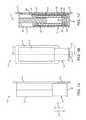
- FIG. 1Aillustrates side view of an interspinous process device according to one embodiment.
- FIG. 1Billustrates a top plan view of the interspinous process device of FIG. 1A .
- FIG. 1Cillustrates a cross-sectional view of the interspinous process device of FIGS. 1A and 1B taken along the line C-C′ of FIG. 1B .
- FIG. 2illustrates a perspective view of the interspinous process device.
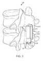
- FIG. 3illustrates an interspinous process device secured to adjacent spinous processes on a subject's spine.
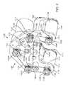
- FIG. 4illustrates a perspective view of an external adjustment device according to one embodiment.
- the outer housing or coveris removed to illustrate the various aspects of the external adjustment device.
- FIG. 5illustrates a side or end view of the external adjustment device of FIG. 4 .
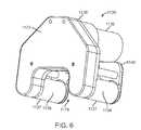
- FIG. 6illustrates a perspective view of an external adjustment device of FIG. 4 with the outer housing or cover in place.
- FIG. 7Aillustrates a cross-sectional representation of the external adjustment device being positioned on a patient's skin.
- FIG. 7Aillustrates the hollow magnet in the 0° position.
- FIG. 7Billustrates a cross-sectional representation of the external adjustment device being positioned on a patient's skin.
- FIG. 7Billustrates the hollow magnet in the 90° position.
- FIG. 7Cillustrates a cross-sectional representation of the external adjustment device being positioned on a patient's skin.
- FIG. 7Cillustrates the hollow magnet in the 180° position.
- FIG. 7Dillustrates a cross-sectional representation of the external adjustment device being positioned on a patient's skin.
- FIG. 7Dillustrates the hollow magnet in the 270° position.
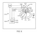
- FIG. 8schematically illustrates a system for driving the external adjustment device according to one embodiment.
- FIG. 9illustrates side view of an interspinous process device according to another embodiment. Hooks are illustrated in a low-profile configuration.
- FIG. 10illustrates side view of an interspinous process device according to another embodiment. Hooks are illustrated in a deployed configuration.
- FIGS. 1A, 1B, and 1Billustrate an interspinous process device 10 according to one embodiment.
- the interspinous process device 10is configured to mount on a subject's spine 100 as illustrated in FIG. 3 .
- the interspinous process device 10is mounted between adjacent spinous processes 102 , 104 .
- the interspinous process device 10is configured to adjust its length in a non-invasive manner.
- an external adjustment device 1130FIGS. 4, 5, 6, 7A-7D, and 8 ) is provided that can lengthen or shorten the interspinous process device 10 on an as needed basis.
- the interspinous process device 10includes a housing 12 that is affixed or otherwise coupled to a first mounting surface 14 .
- the housing 12may be made of any biocompatible, non-magnetic material such as, for instance, stainless steel, titanium or the like.
- a moveable magnetic assembly 16is telescopically disposed within the housing 12 .
- the magnetic assembly 16is moveable in the direction of arrows A and B of FIG. 1A .
- the magnetic assembly 16is affixed or otherwise coupled to a second mounting surface 18 .
- the second mounting surface 18is moveable with respect to the first mounting surface 14 .
- a distraction forceis applied to the adjacent spinous processes 102 , 104 ( FIG. 3 ). This distraction force can be increased by advancing the device an additional amount.
- a compressive forceor relaxing as the case may be, for example, a decreased distraction force
- FIGS. 1A and 1Billustrate side and plan views, respectively, of the interspinous process device 10 .
- FIG. 1Cillustrates a cross-sectional view of the interspinous process device 10 taken along the line C-C′ of FIG. 1B .
- a lead screw 20is fixedly secured at one end to the housing 12 .
- the lead screw 20has threads having, preferably, a very fine pitch, for example, 80 to 100 threads per inch, in order to minimize friction between the lead screw 20 and the a threaded insert (described in more detail below), and thus, minimize the required torque.
- the materials of the lead screw 20may be made from non-magnetic, implantable materials such as titanium, though they may also be made from other magnetic materials such as stainless steel. Additionally, lubrication may be added to the lead screw and/or threaded insert to further minimize friction. For example, biocompatible silicone or Krytox® (perfluorinated polyether-based oil available from DuPont) may be added.
- the magnetic assembly 16itself includes a housing 22 that terminates at one end at an o-ring gland 24 .
- the o-ring gland 24includes a recess 26 dimensioned to receive an o-ring 28 that is compressed between an inner surface of the housing 12 and the recess 26 .
- the o-ring 28thus provides a dynamic sealing surface as the magnetic assembly 16 moves into and out of the housing 12 .
- the opposing end of the magnetic assembly 16includes an end cap 30 that effectively seals the interior of the magnetic assembly 16 from the external environment. End cap 30 is joined with housing 12 by various methods, for example laser or E-beam welding.
- a thrust bearing 32Adjacent to the end cap 30 is a thrust bearing 32 that includes a plurality of ball bearings 34 and a central aperture (not shown) dimensioned to receive an axle 36 of a retaining cup 38 .
- the retaining cup 38is thus rotationally mounted with respect to the thrust bearing 32 .
- the retaining cup 38may be made of stainless steel or a non-magnetic material such as titanium.
- the hollow magnet 40is mounted inside the retaining cup 38 .
- the hollow magnet 40may include, for example, a permanent magnet.
- the hollow magnet 40may be formed from a rare earth magnet, preferably Neodynium-Iron-Boron. Other magnetic materials may be used, including SmCo (Samarium Cobalt), which is typically available as SmCo 5 , or SmCo 15 , Sm 2 Co 17 , or AlNiCo (Aluminum Nickel Cobalt). In still other embodiments, Iron Platinum (Fe—Pt) may be used.
- the hollow magnet 40may be bonded to the interior of the retaining cup 38 using, for example, an adhesive or epoxy.
- a threaded insert 42 having a female threadis located in the hollow portion of the magnet 40 .
- FIG. 1Cillustrates the threaded insert 42 that is located at one end of the hollow magnet 40 .
- the threaded insert 42is bonded or otherwise affixed to an inner surface of the hollow magnet 40 so that when the hollow magnet 40 rotates, the threaded insert 42 rotates in unison.
- FIG. 2illustrates a perspective view of the interspinous process device 10 with the first and second mounting surfaces 14 , 18 exposed for better viewing.
- a channel 44is provided in the first mounting surface 14 and is dimensioned to receive the second mounting surface 18 .
- the channel 44may be milled or otherwise formed with a step or other geometry that enables the second mounting surface 18 to slide back and forth in the direction of arrow C.
- a low friction coatingmay be applied to the channel 44 and/or the interface with the second mounting surface 18 to reduce frictional forces.
- the first and second mounting surfaces 14 , 18may be affixed to the adjacent spinous processes 102 , 104 using any number of affixation techniques known to those skilled in the art. These include, for example, screws, hooks, clamps, and the like.
- FIG. 3illustrates an interspinous process device 10 mounted between adjacent spinous processes 102 , 104 . In this view, the actual affixation mechanism is omitted to better illustrate the relationship between the interspinous process device 10 and the spinous processes 102 , 104 .
- FIGS. 9 and 10show an embodiment having two upward facing hooks 13 (one hook obscured from view) coupled to the two sides of the first mounting surface 14 and one downward facing hook 15 coupled to the second mounting surface 18 .
- Upward facing hooks 13are configured for cradling the lower portion of spinous process 102
- downward facing hook 15is configured for cradling the upper portion of spinous process 104 , allowing the positive displacement of the interspinous process device 10 to distract between the spinous processes 102 , 104 .
- Hooks 13 , 15may additionally be configured to be able to fold, retract, or pivot out of the way during insertion to allow for a less invasive insertion (e.g., a smaller incision results in less trauma).
- Hooks 13 , 15are attached to interspinous process device 10 with axles 17 extending between pairs of mounts 19 .
- the axles 17extend through holes (not shown) in hooks 13 , 15 .
- FIG. 9shows the embodiment with the hooks 13 , 15 folded or pivoted out of the way for a lower profile
- FIG. 10shows the hooks 13 , 15 in position to distract spinous processes 102 , 104 .
- Stops 21are configured to abut flat surface 23 so that hooks 13 , 15 are held static in the configuration of FIG. 10 .
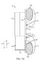
- FIG. 4illustrates an external adjustment device 1130 that may be used to externally impart rotational motion or “drive” the magnetic assembly 16 .
- the external adjustment device 1130includes a motor 1132 that is used to impart rotational movement to two permanent magnets 1134 , 1136 .
- the two permanent magnets 1134 , 1136are located in the same driver 1130 and are configured for placement on the same side of the body of the patient or subject.
- the motor 1132may include, for example, a DC powered motor or servo that is powered via one or more batteries (not shown) integrally contained within the external adjustment device 1130 .
- the motor 1132may be powered via a power cord or the like to an external power source.
- the external power sourcemay include one or more batteries or even an alternating current source that is converted to DC.
- the two permanent magnets 1134 , 1136are preferably cylindrically-shaped permanent magnets.
- the permanent magnetsmay be made from, for example, a rare earth magnet material such as Neodymium-Iron-Boron (NdFeB) although other rare earth magnets are also possible.
- each magnet 1134 , 1136may have a length of around 1.5 inches and a diameter of around 1.0 to 3.5 inches.
- Both magnets 1134 , 1136are diametrically magnetized (poles are perpendicular the longitudinal axis of each permanent magnet 1134 , 1136 ).
- the magnets 1134 , 1136may be contained within a non-magnetic cover or housing 1137 .
- the magnets 1134 , 1136are able to rotate within the stationary housing 1137 that separates the magnets 1134 , 1136 from the external environment.
- the housing 1137is rigid and relatively thin walled at least at the portion directly covering the permanent magnets 1134 , 1136 , in order to minimize the gap between the permanent magnets 1134 , 1136 and the magnetic assembly 16 (not shown in FIGS. 7A-7D for clarity purposes).
- the permanent magnets 1134 , 1136are rotationally mounted between opposing base members 1138 , 1140 .
- Each magnet 1134 , 1136may include axles or spindles 1142 , 1144 mounted on opposing axial faces of each magnet 1134 , 1136 .
- the axles 1142 , 1144may be mounted in respective bearings (not shown) that are mounted in the base members 1138 , 1140 .
- driven pulleys 1150are mounted on one set of axles 1142 and 1144 .
- the driven pulleys 1150may optionally include grooves or teeth 1152 that are used to engage with corresponding grooves or teeth 1156 (partially illustrated in FIG. 5 ) contained within a drive belt (indicated by path 1154 ) or drive chain.
- the external adjustment device 1130includes a drive transmission 1160 that includes the two driven pulleys 1150 along with a plurality of pulleys 1162 A, 1162 B, 1162 C and rollers 1164 A, 1164 B, 1164 C on which the drive belt 1154 is mounted.
- the pulleys 1162 A, 1162 B, 1162 Cmay optionally include grooves or teeth 1166 used for gripping corresponding grooves or teeth 1156 of the drive belt 1154 or drive chain.
- Pulleys 1162 A, 1162 B, 1162 C and rollers 1164 A, 1164 B, 1164 Cmay be mounted on respective bearings (not shown). As seen in FIG.
- pulley 1162 Bis mechanically coupled to the drive shaft (not shown) of the motor 1132 .
- the pulley 1162 Bmay be mounted directly to the drive shaft or, alternatively, may be coupled through appropriate gearing.
- One roller 1164 Bis mounted on a biased arm 1170 and thus provides tension to the belt 1154 .
- the various pulleys 1150 , 1162 A, 1162 B, 1162 C and rollers 1164 A, 1164 B, 1164 C along with the drive belt 1154may be contained within a cover or housing 1172 that is mounted to the base 1138 (as seen in FIG. 6 ).
- the external adjustment device 1130may have a removable safety cover that would be placed over the portion containing the permanent magnets 1134 , 1136 , for example during storage, so that the high magnetic field cannot come closely in contact with anything that would be strongly attracted to it or damaged by it.
- the external adjustment device 1130may also be supplied in a case, for example, a case that has a sheet made of a magnetic shielding material, to minimize the magnetic field external to the case. Giron or mu-metal are two examples of this material.
- rotational movement of the pulley 1162 Bcauses the drive belt 1154 to move around the various pulleys 1150 , 1162 A, 1162 B, 1162 C and rollers 1164 A, 1164 B, 1164 C.
- rotational movement of the motor 1132is translated into rotational movement of the two permanent magnets 1134 , 1136 via the drive transmission 1160 .
- the base members 1138 , 1140are cut so as to form a recess 1174 that is located between the two magnets 1134 , 1136 .
- the external adjustment device 1130is pressed against the skin of a patient, or against the clothing which covers the skin (e.g., the external adjustment device 1130 may be used through clothing so the patient may not need to undress).
- a small permanent magnetmay be temporarily placed on the patient's clothing to determine the location of the hollow magnet 40 (via the attraction of the two magnets).
- the recess 1174allows skin as well as the underlying tissue to gather or compress within the recessed region 1174 as seen in FIGS. 7A and 7B . This advantageously reduces the overall distance between the external drive magnets 1134 , 1136 and the hollow magnet 40 contained within the magnetic assembly 16 . By reducing the distance, this means that the externally located magnets 1134 , 1136 and/or the hollow magnet 40 may be made smaller. This reduction in distance is especially useful in the case of an obese patient.
- the two permanent magnets 1134 , 1136are configured to rotate at the same angular velocity.
- the two permanent magnets 1134 , 1136each have at least one north pole and at least one south pole, and the external adjustment device 1130 is configured to rotate the first magnet 1134 and the second magnet 1136 such that the angular location of the at least one north pole of the first magnet 1134 is substantially equal to the angular location of the at least one south pole of the second magnet 1136 through a full rotation of the first and second magnets 1134 , 1136 .
- FIGS. 7A and 7Billustrate cross-sectional views of the patient having an implanted magnetic assembly (not shown for sake of clarity) with a hollow magnet 40 .
- the hollow magnet 40is seen disposed on one side of a vertebra 1185 although the hollow magnet 40 may be located elsewhere depending on the particular affixation point on the spinous processes.
- FIGS. 7A and 7Billustrate an obese patient in which skin and other tissue gather within the recess 1174 . As seen in FIGS. 7A and 7B the excess skin and other tissue are easily accommodated within the recess 1174 to enable close positioning between the hollow magnet 40 and the external drive magnets 1134 , 1136 .
- the air gap or distance between the hollow magnet 40 and the external drive magnets 1134 , 1136is generally one inch or less.
- the hollow magnet 40is depicted somewhat larger than its actual size in order for its respective poles to be more clearly visible.
- the external adjustment device 1130preferably includes an encoder 1175 that is used to accurately and precisely measure the degree of movement (e.g., rotational) of the external magnets 1134 , 1136 .
- an encoder 1175is mounted on the base member 1138 and includes a light source 1176 and a light receiver 1178 .
- the light source 1176may includes a LED which is pointed or directed toward pulley 1162 C.
- the light receiver 1178may be directed toward the pulley 1162 C.
- the pulley 1162 Cincludes a number of reflective markers 1177 regularly spaced about the periphery of the pulley 1162 C.
- the digital on/off signal generated by the light receiver 1178can then be used to determine the rotational speed and displacement of the external magnets 1134 , 1136 .
- FIGS. 7A, 7B, 7C, and 7Dillustrate the progression of the external magnets 1134 , 1136 and the hollow magnet 40 that is located within the magnetic assembly 16 during use.
- FIGS. 7A, 7B, 7C, and 7Dillustrate the external adjustment device 1130 being disposed against the external surface of the patient's skin 1180 adjacent the spine.
- the patient 100lies in a prone position, and the external adjustment device 1130 is placed upon the patient's back.
- the external adjustment device 1130is placed against the skin 1180 in this manner to remotely rotate the hollow magnet 40 .
- rotation of the hollow magnet 40causes rotational movement of the threaded insert 42 .
- This rotational movementis then translated to the lead screw 20 .
- the magnetic assembly 16moves in a telescopic manner out of or into the housing 12 .
- the hollow magnet 40may have rotational movement though less than 360° of a full rotation.
- the hollow magnet 40may have rotational movement through more than 360° (e.g., multiple, full revolutions).
- the external adjustment device 1130may be pressed down on the patient's skin 1180 with some degree of force such that skin 1180 and other tissue such as the underlying layer of fat 1182 are pressed or forced into the recess 1174 of the external adjustment device 1130 .
- FIGS. 7A, 7B, 7C, and 7Dshow the magnetic orientation of the hollow magnet 40 as it undergoes a full rotation in response to movement of the permanent magnets 1134 , 1136 of the external adjustment device 1130 .
- the hollow magnet 40is shown being oriented with respect to the two permanent magnets 1134 , 1136 via an angle ⁇ .
- This angle ⁇may depend on a number of factors including, for instance, the separation distance between the two permanent magnets 1134 , 1136 , the location or depth of where the hollow magnet 40 is located, the degree of force at which the external adjustment device 1130 is pushed against the patient's skin. Generally in applications including some obese patients, the angle ⁇ should be at or around 90° to achieve maximum drivability (e.g., torque). An angle of about 70° is preferred for the majority of patients when the permanent magnets 1134 , 1136 have an outer diameter of about two (2.0) to three (3.0) inches.
- FIG. 7Aillustrates the initial position of the two permanent magnets 1134 , 1136 and the hollow magnet 40 .
- Thisrepresents the initial or starting location (e.g., 0° position as indicated).
- the particular orientation of the two permanent magnets 1134 , 1136 and the hollow magnet 40will vary and not likely will have the starting orientation as illustrated in FIG. 7A .
- the two permanent magnets 1134 , 1136are oriented with their poles in an N-S/S-N arrangement.
- the hollow magnet 40is, however, oriented generally perpendicular to the poles of the two permanent magnets 1134 , 1136 .
- FIG. 7Billustrates the orientation of the two permanent magnets 1134 , 1136 and the hollow magnet 40 after the two permanent magnets 1134 , 1136 have rotated through 90°.
- the two permanent magnets 1134 , 1136rotate in the direction of arrow A (e.g., clockwise) while the hollow magnet 40 rotates in the opposite direction (e.g., counter clockwise) represented by arrow B.
- the two permanent magnets 1134 , 1136may rotate in the counter clockwise direction while the hollow magnet 40 may rotate in the clockwise direction.
- Rotation of the two permanent magnets 1134 , 1136 and the hollow magnet 40continues as represented by the 180° and 270° orientations as illustrated in FIGS. 7C and 7D . Rotation continues until the starting position) (0°) is reached again.
- the permanent magnets 1134 , 1136may be driven to rotate the hollow magnet 40 through one or more full rotations in either direction to increase or decrease the foramenal distance between spinous processes 102 , 104 .
- the permanent magnets 1134 , 1136may be driven to rotate the hollow magnet 40 through a partial rotation as well (e.g., 1 ⁇ 4, 1 ⁇ 8, 1/16, etc.).
- the use of two magnets 1134 , 1136is preferred over a single external magnet because the hollow magnet 40 may not be oriented perfectly at the start of rotation, so one external magnet 1134 , 1136 may not be able to deliver its maximum torque, which depends on the orientation of the hollow magnet 40 some degree.
- one of the two 1134 or 1136will have an orientation relative to the hollow magnet 40 that is better or more optimal than the other.
- the torques imparted by each external magnet 1134 , 1136are additive.
- the external driving deviceis at the mercy of the particular orientation of the internal driven magnet.
- the two-magnet embodiment described hereinis able to guarantee a larger driving torque—as much as 75% more than a one-magnet embodiment in the spinal application—and thus the hollow magnet 40 can be designed smaller in dimension, and less massive.
- a smaller hollow magnet 40will have a smaller image artifact when performing MRI (Magnetic Resonance Imaging), especially important when using pulse sequences such as gradient echo, which is commonly used in breast imaging, and leads to the largest artifact from implanted magnets.
- MRIMagnetic Resonance Imaging
- FIG. 8illustrates a system 1076 according to one aspect of the invention for driving the external adjustment device 1130 .
- FIG. 8illustrates the external adjustment device 1130 pressed against the surface of a patient 1077 (torso face down shown in cross-section). The portion of the magnetic assembly 16 containing the hollow magnet 40 is illustrated.
- the hollow magnet 40 that is located within the magnetic assembly 16(disposed internally within the patient 1077 is magnetically coupled through the patient's skin and other tissue to the two external magnets 1134 , 1136 located in the external adjustment device 1130 .
- one rotation of the external magnets 1134 , 1136causes a corresponding single rotation of the hollow magnet 40 .
- hollow magnet 40in one direction causes the interspinous process device 10 to lengthen, or increase distraction force while turning in the opposite direction causes the interspinous process device 10 to shorten, or decrease distraction force.
- Changes to the interspinous process device 10are directly related to the number of turns of the hollow magnet 40 .
- a ratchetmay be added which allows motion in one direction, but not the other.
- the devicecould be made to be extendable, but not retractable.
- the motor 1132 of the external adjustment device 1130is controlled via a motor control circuit 1078 operatively connected to a programmable logic controller (PLC) 1080 .
- the PLC 1080outputs an analog signal to the motor control circuit 1078 that is proportional to the desired speed of the motor 1132 .
- the PLC 1080may also select the rotational direction of the motor 1132 (i.e., forward or reverse).
- the PLC 1080receives an input signal from a shaft encoder 1082 that is used to identify with high precision and accuracy the exact relative position of the external magnets 1134 , 1136 .
- the shaft encoder 1082may be an encoder 1175 as described in FIGS. 4-5 .
- the signalis a pulsed, two channel quadrature signal that represents the angular position of the external magnets 1134 , 1136 .
- the PLC 1080may include a built in screen or display 1081 that can display messages, warnings, and the like.
- the PLC 1080may optionally include a keyboard 1083 or other input device for entering data.
- the PLC 1080may be incorporated directly into the external adjustment device 1130 or it may be a separate component that is electrically connected to the main external adjustment device 1130 .
- a sensor 1084is incorporated into the external adjustment device 1130 that is able to sense or determine the rotational or angular position of the hollow magnet 40 .
- the sensor 1084may acquire positional information using, for example, sound waves, ultrasonic waves, radiation (e.g., light), or even changes or perturbations in the magnetic or electromagnetic field between the hollow magnet 40 and the external magnets 1134 , 1136 .
- the sensor 1084may detect photons or light that is reflected from the hollow magnet 40 or a coupled structure (e.g., rotor) that is attached thereto.
- lightmay be passed through the patient's skin and other tissue at wavelength(s) conducive for passage through tissue.
- Portions of the hollow magnet 40 or associated structuremay include a reflective surface that reflects light back outside the patient as the hollow magnet 40 (for instance the magnetic assembly 16 may transmit light at least partially there through). The reflected light can then be detected by the sensor 1084 which may include, for example, a photodetector or the like.
- the senor 1084may operate on the Hall effect, wherein two additional magnets are located within the interspinous process device 10 .
- the additional magnetsmove axially in relation to each other as the hollow magnet 40 rotates and therefore as the distraction increases or decreases, allowing the determination of the current size of the interspinous process device 10 .
- the sensor 1084may be a strain gauge, capable of determining the distraction force.
- a strain gauge or force transducer disposed on a portion of the interspinous process device 10may also be used as an implantable feedback device.
- the strain gaugemay be able to communicate wirelessly the actual distraction force applied to the spine by the interspinous process device 10 .
- a wireless reader or the likemay be used to read the distraction forces.
- One exemplary strain gauge sensoris the EMBEDSENSE wireless sensor, available from MicroStrain, Inc. of Williston, Vt. 05495.
- the EMBEDSENSE wireless sensoruses an inductive link to receive power form an external coil and returns digital stain measurements wirelessly.
- the sensor 1084is a microphone disposed on the external adjustment device 1130 .
- the microphone sensor 1084may be disposed in the recessed portion 1174 of the external adjustment device 1130 .
- the output of the microphone sensor 1084is directed to a signal processing circuit 1086 that amplifies and filters the detected acoustic signal.
- the acoustic signalmay include a “click” or other noise that is periodically generated by rotation of the hollow magnet 40 .
- the hollow magnet 40may click every time a full rotation is made.
- the pitch (frequency) of the clickmay differ depending on the direction of rotation.
- rotation in one directionmay produce a low pitch while rotation in the other direction (e.g., shortening) may produce a higher pitch signal (or vice versa).
- rotation of the hollow magnet 40 in one directione.g., clockwise
- the amplified and filtered signal from the signal processing circuit 1086can then pass to the PLC 1080 .
- medical personnelmay listen for the clicks using a stethoscope or similar instrument.
- each patientwill have a number or indicia that correspond to the adjustment setting or size of their interspinous process device 10 .
- This numbercan be stored on an optional storage device 1088 (as shown in FIG. 8 ) that is carried by the patient (e.g., memory card, magnetic card, or the like) or is integrally formed with the interspinous process device 10 .
- a RFID tag 1088 implanted either as part of the system or separatelymay be disposed inside the patient (e.g., subcutaneously or as part of the device) and can be read and written via an antenna 1090 to update the current size of the interspinous process device 10 .
- the PLC 1080has the ability to read the current number corresponding to the size or setting of the interspinous process device 10 from the storage device 1088 .
- the PLC 1080may also be able to write the adjusted or more updated current size or setting of the interspinous process device 10 to the storage device 1088 .
- the current sizemay recorded manually in the patient's medical records (e.g., chart, card or electronic patient record) that is then viewed and altered, as appropriate, each time the patient visits his or her physician.
- the patienttherefore, carries their medical record with them, and if, for example, they are in another location, or even country, and need to be adjusted, the RFID tag 1088 has all of the information needed.
- the RFID tag 1088may be used as a security device.
- the RFID tag 1088may be used to allow only physicians to adjust the interspinous process device 10 and not patients.
- the RFID tag 1088may be used to allow only certain models or makes of interspinous process devices to be adjusted by a specific model or serial number of external adjustment device 1130 .
- the current size or setting of the interspinous process device 10is input into the PLC 1080 . This may be done automatically or through manual input via, for instance, the keyboard 1083 that is associated with the PLC 1080 .
- the PLC 1080thus knows the patient's starting point. If the patient's records are lost, the length of the interspinous process device 10 may be measured by X-ray and the PLC 1080 may be manually programmed to this known starting point.
- the external adjustment device 1130is commanded to make an adjustment. This may be accomplished via a pre-set command entered into the PLC 1080 (e.g. “increase distraction displacement of interspinous process device 10 by 0.5 mm” or “increase distraction force of interspinous process device 10 to 20 pounds”).
- the PLC 1080configures the proper direction for the motor 1132 and starts rotation of the motor 1132 .
- the encoder 1082is able to continuously monitor the shaft position of the motor directly, as is shown in FIG. 8 , or through another shaft or surface that is mechanically coupled to the motor 1132 .
- the encoder 1082may read the position of markings 1177 located on the exterior of a pulley 1162 C like that disclosed in FIG. 4 . Every rotation or partial rotation of the motor 1132 can then be counted and used to calculate the adjusted or new size or setting of the interspinous process device 10 .
- the sensor 1084which may include a microphone sensor 1084 , may be monitored continuously. For example, every rotation of the motor 1132 should generate the appropriate number and pitch of clicks generated by rotation of the hollow magnet 40 inside the interspinous process device 10 . If the motor 1132 turns a full revolution but no clicks are sensed, the magnetic coupling may have been lost and an error message may be displayed to the operator on a display 1081 of the PLC 1080 . Similarly, an error message may be displayed on the display 1081 if the sensor 1084 acquires the wrong pitch of the auditory signal (e.g., the sensor 1084 detects a shortening pitch but the external adjustment device 1130 was configured to lengthen).
- the devicecan be used for treatment of various descriptions of the source of back pain: spondylolisthesis, degenerative spinal stenosis, disc herniations, instability, discogenic back pain, facet syndrome, and thecal sac changes to name a few.
- the inventiontherefore, should not be limited, except to the following claims, and their equivalents.
Landscapes
- Health & Medical Sciences (AREA)
- Orthopedic Medicine & Surgery (AREA)
- Life Sciences & Earth Sciences (AREA)
- Neurology (AREA)
- Surgery (AREA)
- Heart & Thoracic Surgery (AREA)
- Engineering & Computer Science (AREA)
- Biomedical Technology (AREA)
- Nuclear Medicine, Radiotherapy & Molecular Imaging (AREA)
- Medical Informatics (AREA)
- Molecular Biology (AREA)
- Animal Behavior & Ethology (AREA)
- General Health & Medical Sciences (AREA)
- Public Health (AREA)
- Veterinary Medicine (AREA)
- Prostheses (AREA)
Abstract
Description
Claims (36)
Priority Applications (4)
| Application Number | Priority Date | Filing Date | Title |
|---|---|---|---|
| US12/761,141US9622792B2 (en) | 2009-04-29 | 2010-04-15 | Interspinous process device and method |
| US15/454,899US10478232B2 (en) | 2009-04-29 | 2017-03-09 | Interspinous process device and method |
| US16/597,702US11602380B2 (en) | 2009-04-29 | 2019-10-09 | Interspinous process device and method |
| US18/172,583US20230248398A1 (en) | 2009-04-29 | 2023-02-22 | Interspinous process device and method |
Applications Claiming Priority (2)
| Application Number | Priority Date | Filing Date | Title |
|---|---|---|---|
| US17390209P | 2009-04-29 | 2009-04-29 | |
| US12/761,141US9622792B2 (en) | 2009-04-29 | 2010-04-15 | Interspinous process device and method |
Related Child Applications (1)
| Application Number | Title | Priority Date | Filing Date |
|---|---|---|---|
| US15/454,899ContinuationUS10478232B2 (en) | 2009-04-29 | 2017-03-09 | Interspinous process device and method |
Publications (2)
| Publication Number | Publication Date |
|---|---|
| US20100280551A1 US20100280551A1 (en) | 2010-11-04 |
| US9622792B2true US9622792B2 (en) | 2017-04-18 |
Family
ID=43030971
Family Applications (4)
| Application Number | Title | Priority Date | Filing Date |
|---|---|---|---|
| US12/761,141Active2031-03-24US9622792B2 (en) | 2009-04-29 | 2010-04-15 | Interspinous process device and method |
| US15/454,899Active2030-05-13US10478232B2 (en) | 2009-04-29 | 2017-03-09 | Interspinous process device and method |
| US16/597,702Active2030-08-02US11602380B2 (en) | 2009-04-29 | 2019-10-09 | Interspinous process device and method |
| US18/172,583PendingUS20230248398A1 (en) | 2009-04-29 | 2023-02-22 | Interspinous process device and method |
Family Applications After (3)
| Application Number | Title | Priority Date | Filing Date |
|---|---|---|---|
| US15/454,899Active2030-05-13US10478232B2 (en) | 2009-04-29 | 2017-03-09 | Interspinous process device and method |
| US16/597,702Active2030-08-02US11602380B2 (en) | 2009-04-29 | 2019-10-09 | Interspinous process device and method |
| US18/172,583PendingUS20230248398A1 (en) | 2009-04-29 | 2023-02-22 | Interspinous process device and method |
Country Status (1)
| Country | Link |
|---|---|
| US (4) | US9622792B2 (en) |
Cited By (3)
| Publication number | Priority date | Publication date | Assignee | Title |
|---|---|---|---|---|
| US11065037B2 (en) | 2016-05-19 | 2021-07-20 | Auctus Surgical, Inc. | Spinal curvature modulation systems and methods |
| US12262917B2 (en) | 2016-05-19 | 2025-04-01 | Auctus Surgical, Inc. | Spinal curvature modulation systems and methods |
| US12433649B2 (en) | 2019-02-13 | 2025-10-07 | The Trustees Of The University Of Pennsylvania | Systems and methods for a smart, implantable cranio-maxillo-facial distractor |
Families Citing this family (46)
| Publication number | Priority date | Publication date | Assignee | Title |
|---|---|---|---|---|
| US8273108B2 (en) | 2004-10-20 | 2012-09-25 | Vertiflex, Inc. | Interspinous spacer |
| US8123807B2 (en) | 2004-10-20 | 2012-02-28 | Vertiflex, Inc. | Systems and methods for posterior dynamic stabilization of the spine |
| US7763074B2 (en) | 2004-10-20 | 2010-07-27 | The Board Of Trustees Of The Leland Stanford Junior University | Systems and methods for posterior dynamic stabilization of the spine |
| US9161783B2 (en) | 2004-10-20 | 2015-10-20 | Vertiflex, Inc. | Interspinous spacer |
| US8167944B2 (en) | 2004-10-20 | 2012-05-01 | The Board Of Trustees Of The Leland Stanford Junior University | Systems and methods for posterior dynamic stabilization of the spine |
| US9119680B2 (en) | 2004-10-20 | 2015-09-01 | Vertiflex, Inc. | Interspinous spacer |
| US8409282B2 (en) | 2004-10-20 | 2013-04-02 | Vertiflex, Inc. | Systems and methods for posterior dynamic stabilization of the spine |
| US8152837B2 (en) | 2004-10-20 | 2012-04-10 | The Board Of Trustees Of The Leland Stanford Junior University | Systems and methods for posterior dynamic stabilization of the spine |
| US8128662B2 (en) | 2004-10-20 | 2012-03-06 | Vertiflex, Inc. | Minimally invasive tooling for delivery of interspinous spacer |
| US9023084B2 (en) | 2004-10-20 | 2015-05-05 | The Board Of Trustees Of The Leland Stanford Junior University | Systems and methods for stabilizing the motion or adjusting the position of the spine |
| US8425559B2 (en) | 2004-10-20 | 2013-04-23 | Vertiflex, Inc. | Systems and methods for posterior dynamic stabilization of the spine |
| US8317864B2 (en) | 2004-10-20 | 2012-11-27 | The Board Of Trustees Of The Leland Stanford Junior University | Systems and methods for posterior dynamic stabilization of the spine |
| EP2219538B1 (en) | 2004-12-06 | 2022-07-06 | Vertiflex, Inc. | Spacer insertion instrument |
| US8845726B2 (en) | 2006-10-18 | 2014-09-30 | Vertiflex, Inc. | Dilator |
| AU2008241447B2 (en) | 2007-04-16 | 2014-03-27 | Vertiflex, Inc. | Interspinous spacer |
| AU2009206098B2 (en) | 2008-01-15 | 2014-10-30 | Vertiflex, Inc. | Interspinous spacer |
| US11241257B2 (en) | 2008-10-13 | 2022-02-08 | Nuvasive Specialized Orthopedics, Inc. | Spinal distraction system |
| US9622792B2 (en)* | 2009-04-29 | 2017-04-18 | Nuvasive Specialized Orthopedics, Inc. | Interspinous process device and method |
| US8740948B2 (en) | 2009-12-15 | 2014-06-03 | Vertiflex, Inc. | Spinal spacer for cervical and other vertebra, and associated systems and methods |
| US8376937B2 (en)* | 2010-01-28 | 2013-02-19 | Warsaw Orhtopedic, Inc. | Tissue monitoring surgical retractor system |
| AU2011331999B2 (en) | 2010-11-22 | 2016-07-21 | Synthes Gmbh | Non-fusion scoliosis expandable spinal rod |
| ITVI20110156A1 (en)* | 2011-06-17 | 2012-12-18 | Alexandre Alvise | INTERPINOSIS PERCUTANEOUS SPACER WITH LOW INVASIVITY AND INSTRUMENTATION FOR ITS IMPLANATION |
| US9149306B2 (en) | 2011-06-21 | 2015-10-06 | Seaspine, Inc. | Spinous process device |
| FR2977139B1 (en) | 2011-06-30 | 2014-08-22 | Ldr Medical | INTER-SPINAL IMPLANT AND IMPLANTATION INSTRUMENT |
| US10016220B2 (en)* | 2011-11-01 | 2018-07-10 | Nuvasive Specialized Orthopedics, Inc. | Adjustable magnetic devices and methods of using same |
| US10016226B2 (en) | 2011-12-12 | 2018-07-10 | Children's Hospital Medical Center Of Akron | Noninvasive device for adjusting fastener |
| US9949761B2 (en) | 2011-12-12 | 2018-04-24 | Children's Hospital Medical Center Of Akron | Noninvasive device for adjusting fastener |
| US20130338714A1 (en) | 2012-06-15 | 2013-12-19 | Arvin Chang | Magnetic implants with improved anatomical compatibility |
| US10660674B2 (en)* | 2012-07-17 | 2020-05-26 | Gomboc, LLC | Magnetically levitated spinous process implants and methods thereof |
| US9675303B2 (en) | 2013-03-15 | 2017-06-13 | Vertiflex, Inc. | Visualization systems, instruments and methods of using the same in spinal decompression procedures |
| US10226242B2 (en) | 2013-07-31 | 2019-03-12 | Nuvasive Specialized Orthopedics, Inc. | Noninvasively adjustable suture anchors |
| US10751094B2 (en) | 2013-10-10 | 2020-08-25 | Nuvasive Specialized Orthopedics, Inc. | Adjustable spinal implant |
| AU2015256024B2 (en) | 2014-05-07 | 2020-03-05 | Vertiflex, Inc. | Spinal nerve decompression systems, dilation systems, and methods of using the same |
| US9931138B2 (en)* | 2014-10-15 | 2018-04-03 | Globus Medical, Inc. | Orthopedic extendable rods |
| US9578773B1 (en) | 2015-09-02 | 2017-02-21 | Medline Industries, Inc. | Repair or refurbishment of limited use medical devices |
| WO2018102101A2 (en) | 2016-11-09 | 2018-06-07 | Children's Hospital Medical Center Of Akron | Distraction osteogenesis system |
| US11678995B2 (en) | 2018-07-20 | 2023-06-20 | Fellowship Of Orthopaedic Researchers, Inc. | Magnetic intervertebral disc replacement devices and methods thereof |
| CN110584841B (en)* | 2019-09-30 | 2024-04-12 | 北京爱康宜诚医疗器材有限公司 | Extensible prosthesis |
| US12011360B2 (en) | 2021-10-22 | 2024-06-18 | Linares Spinal Devices, Llc | Expandable spinal jack for installation between upper and lower succeeding superior articular processes |
| US11432937B1 (en) | 2021-11-02 | 2022-09-06 | Linares Medical Devices, Llc | Expandable spinal jack for installation between upper and lower succeeding superior articular processes |
| US12137947B2 (en) | 2021-11-02 | 2024-11-12 | Linares Spinal Devices, Llc | Expandable spinal jack for installation between upper and lower succeeding superior articular processes |
| WO2023158581A1 (en) | 2022-02-15 | 2023-08-24 | Boston Scientific Neuromodulation Corporation | Interspinous spacer and systems utilizing the interspinous spacer |
| US12232790B2 (en) | 2022-12-30 | 2025-02-25 | IvyTech Design LLC | Adjustable angle orthopedic distractor, compressor, and distractor-compressor |
| US12433646B2 (en) | 2023-02-21 | 2025-10-07 | Boston Scientific Neuromodulation Corporation | Interspinous spacer with actuator locking arrangements and methods and systems |
| US12390340B2 (en) | 2023-03-15 | 2025-08-19 | Boston Scientific Neuromodulation Corporation | Interspinous spacer with a range of deployment positions and methods and systems |
| CN117442394B (en)* | 2023-12-25 | 2024-03-08 | 北京爱康宜诚医疗器材有限公司 | Linkage type vertebral body prosthesis |
Citations (90)
| Publication number | Priority date | Publication date | Assignee | Title |
|---|---|---|---|---|
| US5290312A (en)* | 1991-09-03 | 1994-03-01 | Alphatec | Artificial vertebral body |
| US5676665A (en)* | 1995-06-23 | 1997-10-14 | Bryan; Donald W. | Spinal fixation apparatus and method |
| US5704939A (en) | 1996-04-09 | 1998-01-06 | Justin; Daniel F. | Intramedullary skeletal distractor and method |
| US6022349A (en)* | 1997-02-12 | 2000-02-08 | Exogen, Inc. | Method and system for therapeutically treating bone fractures and osteoporosis |
| US6126664A (en) | 1999-01-19 | 2000-10-03 | Synthes (Usa) | Device and method for locating and resecting bone |
| US6375682B1 (en) | 2001-08-06 | 2002-04-23 | Lewis W. Fleischmann | Collapsible, rotatable and expandable spinal hydraulic prosthetic device |
| US6416516B1 (en) | 1999-02-16 | 2002-07-09 | Wittenstein Gmbh & Co. Kg | Active intramedullary nail for the distraction of bone parts |
| US6417750B1 (en) | 1994-05-02 | 2002-07-09 | Srs Medical Systems, Inc. | Magnetically-coupled implantable medical devices |
| US20030144669A1 (en) | 2001-12-05 | 2003-07-31 | Robinson Randolph C. | Limb lengthener |
| US20040023623A1 (en) | 2000-11-09 | 2004-02-05 | Roman Stauch | Device for controlling, regulating and/or putting an active implant into operation |
| US20040030395A1 (en)* | 2000-04-13 | 2004-02-12 | Gordon Blunn | Surgical distraction device |
| US6706042B2 (en) | 2001-03-16 | 2004-03-16 | Finsbury (Development) Limited | Tissue distractor |
| US20050090823A1 (en) | 2003-10-28 | 2005-04-28 | Bartimus Christopher S. | Posterior fixation system |
| US20050096744A1 (en)* | 2003-11-05 | 2005-05-05 | Sdgi Holdings, Inc. | Compressible corpectomy device |
| US20050159754A1 (en) | 2004-01-21 | 2005-07-21 | Odrich Ronald B. | Periosteal distraction bone growth |
| US20050244499A1 (en) | 2004-05-03 | 2005-11-03 | Robert Diaz | Method and device for reducing susceptibility to fractures in long bones |
| US20060004459A1 (en)* | 2004-06-30 | 2006-01-05 | Hazebrouck Stephen A | Adjustable orthopaedic prosthesis and associated method |
| US20060079897A1 (en)* | 2004-09-29 | 2006-04-13 | Harrison Michael R | Apparatus and methods for magnetic alteration of anatomical features |
| US7063706B2 (en) | 2001-11-19 | 2006-06-20 | Wittenstein Ag | Distraction device |
| WO2006090380A2 (en) | 2005-02-22 | 2006-08-31 | Orthogon Technologies 2003 Ltd. | Device and method for vertebral column distraction and oscillation |
| US20060235424A1 (en) | 2005-04-01 | 2006-10-19 | Foster-Miller, Inc. | Implantable bone distraction device and method |
| US20060241614A1 (en)* | 2005-04-12 | 2006-10-26 | Sdgi Holdings, Inc. | Implants and methods for posterior dynamic stabilization of a spinal motion segment |
| US20060241601A1 (en)* | 2005-04-08 | 2006-10-26 | Trautwein Frank T | Interspinous vertebral and lumbosacral stabilization devices and methods of use |
| US20060293683A1 (en) | 2003-04-16 | 2006-12-28 | Roman Stauch | Device for lengthening bones or bone parts |
| US20060293662A1 (en)* | 2005-06-13 | 2006-12-28 | Boyer Michael L Ii | Spinous process spacer |
| US20070010814A1 (en) | 2003-08-28 | 2007-01-11 | Roman Stauch | Device for extending bones |
| WO2007015239A2 (en) | 2005-08-01 | 2007-02-08 | Orthogon Technologies 2003 Ltd. | An implantable magnetically activated actuator |
| US20070093823A1 (en)* | 2005-09-29 | 2007-04-26 | Nuvasive, Inc. | Spinal distraction device and methods of manufacture and use |
| US20070173837A1 (en) | 2005-11-18 | 2007-07-26 | William Marsh Rice University | Bone fixation and dynamization devices and methods |
| US20070173826A1 (en)* | 2006-01-20 | 2007-07-26 | Alpha Orthopaedics | Intramedullar devices and methods to reduce and/or fix damaged bone |
| US20070213751A1 (en)* | 2006-03-13 | 2007-09-13 | Scirica Paul A | Transdermal magnetic coupling gastric banding |
| WO2007118179A2 (en) | 2006-04-06 | 2007-10-18 | Synthes (U.S.A.) | Remotely adjustable tissue displacement device |
| US20070255413A1 (en)* | 2006-04-27 | 2007-11-01 | Sdgi Holdings, Inc. | Expandable intervertebral spacers and methods of use |
| US20070264605A1 (en) | 2005-05-19 | 2007-11-15 | Theodore Belfor | System and method to bioengineer facial form in adults |
| US20070276378A1 (en)* | 2004-09-29 | 2007-11-29 | The Regents Of The University Of California | Apparatus and methods for magnetic alteration of anatomical features |
| US20070276369A1 (en)* | 2006-05-26 | 2007-11-29 | Sdgi Holdings, Inc. | In vivo-customizable implant |
| US20070276368A1 (en) | 2006-05-23 | 2007-11-29 | Sdgi Holdings, Inc. | Systems and methods for adjusting properties of a spinal implant |
| US20080027435A1 (en) | 2006-06-22 | 2008-01-31 | St. Francis Medical Technologies, Inc. | System and method for strengthening a spinous process |
| US20080033436A1 (en)* | 2004-08-30 | 2008-02-07 | Vermillion Technologies, Llc | Device and method for treatment of spinal deformity |
| US20080039943A1 (en) | 2004-05-25 | 2008-02-14 | Regis Le Couedic | Set For Treating The Degeneracy Of An Intervertebral Disc |
| US20080051800A1 (en) | 2004-05-03 | 2008-02-28 | Robert Diaz | Method and device for reducing susceptibility to fractures in vertebral bodies |
| US7357635B2 (en) | 2004-05-19 | 2008-04-15 | Orthovisage Inc. | System and method to bioengineer facial form in adults |
| US20080097496A1 (en)* | 2006-10-20 | 2008-04-24 | Arvin Chang | System and method for securing an implantable interface to a mammal |
| US20080097188A1 (en) | 2006-10-20 | 2008-04-24 | Ellipse Technologies, Inc. | External sensing systems and methods for gastric restriction devices |
| US20080161933A1 (en) | 2005-09-26 | 2008-07-03 | Innvotec Surgical, Inc. | Selectively expanding spine cage, hydraulically controllable in three dimensions for vertebral body replacement |
| US20080167685A1 (en) | 2007-01-05 | 2008-07-10 | Warsaw Orthopedic, Inc. | System and Method For Percutanously Curing An Implantable Device |
| US20080172072A1 (en) | 2007-01-11 | 2008-07-17 | Ellipse Technologies, Inc. | Internal sensors for use with gastric restriction devices |
| US20080228186A1 (en) | 2005-04-01 | 2008-09-18 | The Regents Of The University Of Colorado | Graft Fixation Device |
| US20080255615A1 (en) | 2007-03-27 | 2008-10-16 | Warsaw Orthopedic, Inc. | Treatments for Correcting Spinal Deformities |
| US7458981B2 (en)* | 2004-03-09 | 2008-12-02 | The Board Of Trustees Of The Leland Stanford Junior University | Spinal implant and method for restricting spinal flexion |
| US20090030462A1 (en) | 2007-07-26 | 2009-01-29 | Glenn R. Buttermann, M.D. | Segmental Orthopaedic device for spinal elongation and for treatment of Scoliosis |
| US20090076597A1 (en) | 2007-09-19 | 2009-03-19 | Jonathan Micheal Dahlgren | System for mechanical adjustment of medical implants |
| US20090093890A1 (en) | 2007-10-04 | 2009-04-09 | Daniel Gelbart | Precise control of orthopedic actuators |
| US20090112262A1 (en) | 2007-10-30 | 2009-04-30 | Scott Pool | Skeletal manipulation system |
| US7531002B2 (en) | 2004-04-16 | 2009-05-12 | Depuy Spine, Inc. | Intervertebral disc with monitoring and adjusting capabilities |
| US20090125062A1 (en) | 2007-11-08 | 2009-05-14 | Uri Arnin | Spinal implant having a post-operative adjustable dimension |
| US20090171356A1 (en) | 2008-01-02 | 2009-07-02 | International Business Machines Corporation | Bone Repositioning Apparatus and System |
| US20090192514A1 (en) | 2007-10-09 | 2009-07-30 | Feinberg Stephen E | Implantable distraction osteogenesis device and methods of using same |
| US20090248148A1 (en)* | 2008-03-25 | 2009-10-01 | Ellipse Technologies, Inc. | Systems and methods for adjusting an annuloplasty ring with an integrated magnetic drive |
| US20090248079A1 (en)* | 2008-03-26 | 2009-10-01 | Kwak Seungkyu Daniel | S-Shaped Interspinous Process Spacer Having Tight Access Offset Hooks |
| US20090264929A1 (en)* | 2006-10-19 | 2009-10-22 | Simpirica Spine, Inc. | Structures and methods for constraining spinal processes with single connector |
| US7608104B2 (en)* | 2003-05-14 | 2009-10-27 | Archus Orthopedics, Inc. | Prostheses, tools and methods for replacement of natural facet joints with artifical facet joint surfaces |
| US7611526B2 (en) | 2004-08-03 | 2009-11-03 | K Spine, Inc. | Spinous process reinforcement device and method |
| US7666184B2 (en) | 2003-08-28 | 2010-02-23 | Wittenstein Ag | Planetary roll system, in particular for a device for extending bones |
| US20100049204A1 (en)* | 2006-10-03 | 2010-02-25 | Arnaud Soubeiran | Intracorporeal elongation device with a permanent magnet |
| US20100100185A1 (en) | 2008-10-22 | 2010-04-22 | Warsaw Orthopedic, Inc. | Intervertebral Disc Prosthesis Having Viscoelastic Properties |
| US20100114103A1 (en)* | 2008-11-06 | 2010-05-06 | The Regents Of The University Of California | Apparatus and methods for alteration of anatomical features |
| US20100137911A1 (en)* | 2008-12-03 | 2010-06-03 | Zimmer Spine, Inc. | Adjustable Assembly for Correcting Spinal Abnormalities |
| US7776091B2 (en)* | 2004-06-30 | 2010-08-17 | Depuy Spine, Inc. | Adjustable posterior spinal column positioner |
| US7794476B2 (en) | 2003-08-08 | 2010-09-14 | Warsaw Orthopedic, Inc. | Implants formed of shape memory polymeric material for spinal fixation |
| US20100249847A1 (en) | 2006-06-29 | 2010-09-30 | Searete Llc, A Limited Liability Corporation Of The State Of Delaware | Position augmenting mechanism |
| US7811328B2 (en) | 2005-04-29 | 2010-10-12 | Warsaw Orthopedic, Inc. | System, device and methods for replacing the intervertebral disc with a magnetic or electromagnetic prosthesis |
| US7862502B2 (en) | 2006-10-20 | 2011-01-04 | Ellipse Technologies, Inc. | Method and apparatus for adjusting a gastrointestinal restriction device |
| US7887566B2 (en) | 2004-09-16 | 2011-02-15 | Hynes Richard A | Intervertebral support device with bias adjustment and related methods |
| US20110118848A1 (en)* | 2008-08-06 | 2011-05-19 | Giovanni Faccioli | Modular spacer device for the treatment of prosthesis infections |
| US7955357B2 (en) | 2004-07-02 | 2011-06-07 | Ellipse Technologies, Inc. | Expandable rod system to treat scoliosis and method of using the same |
| US20110257655A1 (en) | 2008-10-02 | 2011-10-20 | Copf Jr Franz | Instrument for measuring the distraction pressure between vertebral bodies |
| US8043299B2 (en) | 2006-11-06 | 2011-10-25 | Janet Conway | Internal bone transport |
| US8147549B2 (en) | 2008-11-24 | 2012-04-03 | Warsaw Orthopedic, Inc. | Orthopedic implant with sensor communications antenna and associated diagnostics measuring, monitoring, and response system |
| US8177789B2 (en) | 2007-10-01 | 2012-05-15 | The General Hospital Corporation | Distraction osteogenesis methods and devices |
| US8221420B2 (en) | 2009-02-16 | 2012-07-17 | Aoi Medical, Inc. | Trauma nail accumulator |
| US20120203282A1 (en) | 2007-06-06 | 2012-08-09 | K Spine, Inc. | Medical device and method to correct deformity |
| US8252063B2 (en) | 2009-03-04 | 2012-08-28 | Wittenstein Ag | Growing prosthesis |
| US8298240B2 (en) | 2006-04-06 | 2012-10-30 | Synthes (Usa) | Remotely adjustable tissue displacement device |
| US8419801B2 (en) | 2004-09-30 | 2013-04-16 | DePuy Synthes Products, LLC | Adjustable, remote-controllable orthopaedic prosthesis and associated method |
| US8469908B2 (en) | 2007-04-06 | 2013-06-25 | Wilson T. Asfora | Analgesic implant device and system |
| US8529606B2 (en) | 2009-03-10 | 2013-09-10 | Simpirica Spine, Inc. | Surgical tether apparatus and methods of use |
| US8562653B2 (en) | 2009-03-10 | 2013-10-22 | Simpirica Spine, Inc. | Surgical tether apparatus and methods of use |
| US8632544B2 (en) | 2008-03-19 | 2014-01-21 | Synoste Oy | Internal osteodistraction device |
| US20150105824A1 (en) | 2005-04-12 | 2015-04-16 | Nathan C. Moskowitz | Bi-directional fixating transvertebral body screws, zero-profile horizontal intervertebral miniplates, total intervertebral body fusion devices, and posterior motion-calibrating interarticulating joint stapling device for spinal fusion |
Family Cites Families (737)
| Publication number | Priority date | Publication date | Assignee | Title |
|---|---|---|---|---|
| US1599538A (en) | 1919-12-06 | 1926-09-14 | Mintrop Ludger | Geological testing method |
| US2702031A (en) | 1953-09-25 | 1955-02-15 | Wenger Herman Leslie | Method and apparatus for treatment of scoliosis |
| US3111945A (en) | 1961-01-05 | 1963-11-26 | Solbrig Charles R Von | Bone band and process of applying the same |
| US3377576A (en) | 1965-05-03 | 1968-04-09 | Metcom Inc | Gallium-wetted movable electrode switch |
| US3397928A (en) | 1965-11-08 | 1968-08-20 | Edward M. Galle | Seal means for drill bit bearings |
| US3372476A (en) | 1967-04-05 | 1968-03-12 | Amp Inc | Method of making permanent connections between interfitting parts |
| FR1556730A (en) | 1967-06-05 | 1969-02-07 | ||
| US3866510A (en) | 1967-06-05 | 1975-02-18 | Carl B H Eibes | Self-tapping threaded bushings |
| USRE28907E (en) | 1967-06-05 | 1976-07-20 | Self-tapping threaded bushings | |
| US3512901A (en) | 1967-07-28 | 1970-05-19 | Carrier Corp | Magnetically coupled pump with slip detection means |
| US3527220A (en) | 1968-06-28 | 1970-09-08 | Fairchild Hiller Corp | Implantable drug administrator |
| FR2086747A5 (en) | 1970-04-07 | 1971-12-31 | Cotton De Bennetot M | |
| US3726279A (en) | 1970-10-08 | 1973-04-10 | Carolina Medical Electronics I | Hemostatic vascular cuff |
| US3810259A (en) | 1971-01-25 | 1974-05-14 | Fairchild Industries | Implantable urinary control apparatus |
| US3750194A (en) | 1971-03-16 | 1973-08-07 | Fairchild Industries | Apparatus and method for reversibly closing a natural or implanted body passage |
| US3840018A (en) | 1973-01-31 | 1974-10-08 | M Heifetz | Clamp for occluding tubular conduits in the human body |
| DE2314573C2 (en) | 1973-03-23 | 1986-12-18 | Werner Dipl.-Ing. 8000 München Kraus | Device for promoting healing processes |
| GB1467248A (en) | 1973-07-30 | 1977-03-16 | Horstmann Magnetics Ltd | Electric motors |
| CH581988A5 (en) | 1974-04-09 | 1976-11-30 | Messerschmitt Boelkow Blohm | |
| US3900025A (en) | 1974-04-24 | 1975-08-19 | Jr Walter P Barnes | Apparatus for distracting or compressing longitudinal bone segments |
| FI53062C (en) | 1975-05-30 | 1978-02-10 | Erkki Einari Nissinen | |
| US4010758A (en) | 1975-09-03 | 1977-03-08 | Medtronic, Inc. | Bipolar body tissue electrode |
| US4068821A (en) | 1976-09-13 | 1978-01-17 | Acf Industries, Incorporated | Valve seat ring having a corner groove to receive an elastic seal ring |
| SU715082A1 (en) | 1977-01-24 | 1980-02-15 | Всесоюзный научно-исследовательский и испытательный институт медицинской техники | Surgical suturing apparatus |
| US4118805A (en) | 1977-02-28 | 1978-10-10 | Codman & Shurtleff, Inc. | Artificial sphincter |
| CH625384B (en) | 1977-12-20 | Ebauches Electroniques Sa | STEP MOTOR NON-ROTATION DETECTION DEVICE FOR CLOCKWORK PART AND LOST STEPS CATCHING UP. | |
| US4286584A (en) | 1978-06-16 | 1981-09-01 | Infusaid Corporation | Septum locating apparatus |
| US4222374A (en) | 1978-06-16 | 1980-09-16 | Metal Bellows Corporation | Septum locating apparatus |
| US4235246A (en) | 1979-02-05 | 1980-11-25 | Arco Medical Products Company | Epicardial heart lead and assembly and method for optimal fixation of same for cardiac pacing |
| US4256094A (en) | 1979-06-18 | 1981-03-17 | Kapp John P | Arterial pressure control system |
| US4357946A (en) | 1980-03-24 | 1982-11-09 | Medtronic, Inc. | Epicardial pacing lead with stylet controlled helical fixation screw |
| DE3035670A1 (en) | 1980-09-22 | 1982-04-29 | Siemens AG, 1000 Berlin und 8000 München | DEVICE FOR INFUSING LIQUIDS IN HUMAN OR ANIMAL BODIES |
| US4386603A (en) | 1981-03-23 | 1983-06-07 | Mayfield Jack K | Distraction device for spinal distraction systems |
| US4448191A (en) | 1981-07-07 | 1984-05-15 | Rodnyansky Lazar I | Implantable correctant of a spinal curvature and a method for treatment of a spinal curvature |
| FR2514250A1 (en) | 1981-10-08 | 1983-04-15 | Artus | HANDPIECE WITH INTEGRATED MOTOR |
| FR2523232B1 (en) | 1982-03-09 | 1985-09-20 | Thomson Csf | TELESCOPIC COLUMN WITH CYLINDRICAL TUBES |
| CH648723GA3 (en) | 1982-09-10 | 1985-04-15 | ||
| DE3340596A1 (en) | 1982-11-16 | 1984-05-24 | Tokyo Electric Co., Ltd., Tokyo | MATRIX PRINTER |
| IL67773A (en) | 1983-01-28 | 1985-02-28 | Antebi E | Tie for tying live tissue and an instrument for performing said tying operation |
| DE3306657C2 (en) | 1983-02-25 | 1986-12-11 | Fa. Heinrich C. Ulrich, 7900 Ulm | Spine correction implant with a distraction rod |
| US4501266A (en) | 1983-03-04 | 1985-02-26 | Biomet, Inc. | Knee distraction device |
| US4595007A (en) | 1983-03-14 | 1986-06-17 | Ethicon, Inc. | Split ring type tissue fastener |
| FR2551350B1 (en) | 1983-09-02 | 1985-10-25 | Buffet Jacques | FLUID INJECTION DEVICE, SUITABLE FOR IMPLANTATION |
| US4522501A (en) | 1984-04-06 | 1985-06-11 | Northern Telecom Limited | Monitoring magnetically permeable particles in admixture with a fluid carrier |
| US4573454A (en) | 1984-05-17 | 1986-03-04 | Hoffman Gregory A | Spinal fixation apparatus |
| SE448812B (en) | 1985-02-01 | 1987-03-23 | Astra Meditec Ab | SURGICAL DEVICE FOR CONNECTING THE TAGS OF A PATIENT |
| DE8515687U1 (en) | 1985-05-29 | 1985-10-24 | Aesculap-Werke Ag Vormals Jetter & Scheerer, 7200 Tuttlingen | Distraction device for extension osteotomy |
| US4592339A (en) | 1985-06-12 | 1986-06-03 | Mentor Corporation | Gastric banding device |
| US4642257A (en) | 1985-06-13 | 1987-02-10 | Michael Chase | Magnetic occluding device |
| US4696288A (en) | 1985-08-14 | 1987-09-29 | Kuzmak Lubomyr I | Calibrating apparatus and method of using same for gastric banding surgery |
| US4931055A (en) | 1986-05-30 | 1990-06-05 | John Bumpus | Distraction rods |
| US4700091A (en) | 1986-08-22 | 1987-10-13 | Timex Corporation | Bipolar stepping motor rotor with drive pinion and method of manufacture |
| SE460301B (en) | 1986-10-15 | 1989-09-25 | Sandvik Ab | CUTTING ROD FOR STOCKING DRILLING MACHINE |
| US4760837A (en) | 1987-02-19 | 1988-08-02 | Inamed Development Company | Apparatus for verifying the position of needle tip within the injection reservoir of an implantable medical device |
| DE8704134U1 (en) | 1987-03-19 | 1987-07-16 | Zielke, Klaus, Dr.med., 3590 Bad Wildungen | Implant designed as a distraction and compression rod |
| DE3711091A1 (en) | 1987-04-02 | 1988-10-13 | Kluger Patrick | DEVICE FOR SETTING UP A SPINE WITH A DAMAGED SPINE |
| DE3728686A1 (en) | 1987-08-27 | 1989-03-09 | Draenert Klaus | PREDICTABLE SURGICAL NETWORK |
| US4940467A (en) | 1988-02-03 | 1990-07-10 | Tronzo Raymond G | Variable length fixation device |
| FR2632514B1 (en) | 1988-06-09 | 1990-10-12 | Medinov Sarl | PROGRESSIVE CENTRO-MEDULAR NAIL |
| US4904861A (en) | 1988-12-27 | 1990-02-27 | Hewlett-Packard Company | Optical encoder using sufficient inactive photodetectors to make leakage current equal throughout |
| US4998013A (en) | 1988-12-27 | 1991-03-05 | Hewlett-Packard Company | Optical encoder with inactive photodetectors |
| US5180380A (en) | 1989-03-08 | 1993-01-19 | Autogenesis Corporation | Automatic compression-distraction-torsion method and apparatus |
| US4973331A (en) | 1989-03-08 | 1990-11-27 | Autogenesis Corporation | Automatic compression-distraction-torsion method and apparatus |
| JPH0620466B2 (en) | 1989-03-31 | 1994-03-23 | 有限会社田中医科器械製作所 | Spinal column correction device |
| US5092889A (en) | 1989-04-14 | 1992-03-03 | Campbell Robert M Jr | Expandable vertical prosthetic rib |
| US5222976A (en) | 1989-05-16 | 1993-06-29 | Inbae Yoon | Suture devices particularly useful in endoscopic surgery |
| US5053047A (en) | 1989-05-16 | 1991-10-01 | Inbae Yoon | Suture devices particularly useful in endoscopic surgery and methods of suturing |
| DE3921972C2 (en) | 1989-07-04 | 1994-06-09 | Rainer Dr Med Baumgart | Intramedullary nail |
| US5176618A (en) | 1989-08-10 | 1993-01-05 | George Freedman | System for preventing closure of passageways |
| US4978323A (en) | 1989-08-10 | 1990-12-18 | George Freedman | System and method for preventing closure of passageways |
| IT1236172B (en) | 1989-11-30 | 1993-01-11 | Franco Mingozzi | EXTERNAL FIXER FOR THE TREATMENT OF LONG BONE FRACTURES OF THE LIMBS. |
| US5142407A (en) | 1989-12-22 | 1992-08-25 | Donnelly Corporation | Method of reducing leakage current in electrochemichromic solutions and solutions based thereon |
| SE464558B (en) | 1990-03-22 | 1991-05-13 | Hepar Ab | IMPLANTABLE DEVICE FOR SUSPENSION OF A CHANNEL IN THE BODY OF A LIVE BEING |
| US5030235A (en) | 1990-04-20 | 1991-07-09 | Campbell Robert M Jr | Prosthetic first rib |
| US5290289A (en) | 1990-05-22 | 1994-03-01 | Sanders Albert E | Nitinol spinal instrumentation and method for surgically treating scoliosis |
| US5156605A (en) | 1990-07-06 | 1992-10-20 | Autogenesis Corporation | Automatic internal compression-distraction-method and apparatus |
| US5074868A (en) | 1990-08-03 | 1991-12-24 | Inamed Development Company | Reversible stoma-adjustable gastric band |
| US5133716A (en) | 1990-11-07 | 1992-07-28 | Codespi Corporation | Device for correction of spinal deformities |
| US5226429A (en) | 1991-06-20 | 1993-07-13 | Inamed Development Co. | Laparoscopic gastric band and method |
| US5399168A (en) | 1991-08-29 | 1995-03-21 | C. R. Bard, Inc. | Implantable plural fluid cavity port |
| US5360407A (en) | 1991-08-29 | 1994-11-01 | C. R. Bard, Inc. | Implantable dual access port with tactile ridge for position sensing |
| US5433721A (en) | 1992-01-17 | 1995-07-18 | Ethicon, Inc. | Endoscopic instrument having a torsionally stiff drive shaft for applying fasteners to tissue |
| AU4630393A (en) | 1992-06-08 | 1994-01-04 | Robert M. Campbell Jr. | Segmental rib carriage instrumentation and associated methods |
| DE4221692A1 (en) | 1992-07-02 | 1994-01-05 | Siemens Ag | Method and device for determining a mixture proportion of a gas mixture |
| US5437266A (en) | 1992-07-02 | 1995-08-01 | Mcpherson; William | Coil screw surgical retractor |
| US5676651A (en) | 1992-08-06 | 1997-10-14 | Electric Boat Corporation | Surgically implantable pump arrangement and method for pumping body fluids |
| US5601224A (en) | 1992-10-09 | 1997-02-11 | Ethicon, Inc. | Surgical instrument |
| US5381943A (en) | 1992-10-09 | 1995-01-17 | Ethicon, Inc. | Endoscopic surgical stapling instrument with pivotable and rotatable staple cartridge |
| US5466261A (en) | 1992-11-19 | 1995-11-14 | Wright Medical Technology, Inc. | Non-invasive expandable prosthesis for growing children |
| US5498262A (en) | 1992-12-31 | 1996-03-12 | Bryan; Donald W. | Spinal fixation apparatus and method |
| US5306275A (en) | 1992-12-31 | 1994-04-26 | Bryan Donald W | Lumbar spine fixation apparatus and method |
| US5336223A (en) | 1993-02-04 | 1994-08-09 | Rogers Charles L | Telescoping spinal fixator |
| US5356424A (en) | 1993-02-05 | 1994-10-18 | American Cyanamid Co. | Laparoscopic suturing device |
| US5429638A (en) | 1993-02-12 | 1995-07-04 | The Cleveland Clinic Foundation | Bone transport and lengthening system |
| US5626579A (en) | 1993-02-12 | 1997-05-06 | The Cleveland Clinic Foundation | Bone transport and lengthening system |
| US5356411A (en) | 1993-02-18 | 1994-10-18 | Spievack Alan R | Bone transporter |
| US5449368A (en) | 1993-02-18 | 1995-09-12 | Kuzmak; Lubomyr I. | Laparoscopic adjustable gastric banding device and method for implantation and removal thereof |
| US5536269A (en) | 1993-02-18 | 1996-07-16 | Genesis Orthopedics | Bone and tissue lengthening device |
| US5516335A (en) | 1993-03-24 | 1996-05-14 | Hospital For Joint Diseases Orthopaedic Institute | Intramedullary nail for femoral lengthening |
| US5364396A (en) | 1993-03-29 | 1994-11-15 | Robinson Randolph C | Distraction method and apparatus |
| US5334202A (en) | 1993-04-06 | 1994-08-02 | Carter Michael A | Portable bone distraction apparatus |
| US5527309A (en) | 1993-04-21 | 1996-06-18 | The Trustees Of Columbia University In The City Of New York | Pelvo-femoral fixator |
| US5403322A (en) | 1993-07-08 | 1995-04-04 | Smith & Nephew Richards Inc. | Drill guide and method for avoiding intramedullary nails in the placement of bone pins |
| FR2709246B1 (en) | 1993-08-27 | 1995-09-29 | Martin Jean Raymond | Dynamic implanted spinal orthosis. |
| US5468030A (en) | 1994-01-04 | 1995-11-21 | Caterpillar Inc. | Tube clamp and coupling |
| AU1011595A (en) | 1994-01-13 | 1995-07-20 | Ethicon Inc. | Spiral surgical tack |
| US6217847B1 (en) | 1994-07-01 | 2001-04-17 | The Board Of Trustees Of The Leland Stanford Junior University | Non-invasive localization of a light-emitting conjugate in a mammal |
| US7255851B2 (en) | 1994-07-01 | 2007-08-14 | The Board Of Trustees Of The Leland Stanford Junior University | Non-invasive localization of a light-emitting conjugate in a mammal |
| EP0769928B1 (en) | 1994-07-11 | 1999-02-24 | Dacomed Corporation | Vessel occlusive apparatus |
| US5620445A (en) | 1994-07-15 | 1997-04-15 | Brosnahan; Robert | Modular intramedullary nail |
| US5509888A (en) | 1994-07-26 | 1996-04-23 | Conceptek Corporation | Controller valve device and method |
| IT1268313B1 (en) | 1994-07-28 | 1997-02-27 | Orthofix Srl | MECHANICAL EQUIPMENT FOR CENTERING BLIND HOLES FOR BONE SCREWS OF INTRAMIDOLLAR NAILS |
| US5582616A (en) | 1994-08-05 | 1996-12-10 | Origin Medsystems, Inc. | Surgical helical fastener with applicator |
| US5573012A (en) | 1994-08-09 | 1996-11-12 | The Regents Of The University Of California | Body monitoring and imaging apparatus and method |
| US5549610A (en) | 1994-10-31 | 1996-08-27 | Smith & Nephew Richards Inc. | Femoral intramedullary nail |
| WO1996015377A1 (en) | 1994-11-16 | 1996-05-23 | Soubeiran Arnaud Andre | Device for mutually moving two bodies |
| US5874796A (en) | 1995-02-10 | 1999-02-23 | Petersen; Christian C. | Permanent magnet D.C. motor having a radially-disposed working flux gap |
| US5659217A (en) | 1995-02-10 | 1997-08-19 | Petersen; Christian C. | Permanent magnet d.c. motor having a radially-disposed working flux gap |
| FR2730406B1 (en) | 1995-02-13 | 1997-08-14 | Medinov Sa | IMPROVED LENGTHENING DEVICE FOR LONG BONES |
| US5575790A (en) | 1995-03-28 | 1996-11-19 | Rensselaer Polytechnic Institute | Shape memory alloy internal linear actuator for use in orthopedic correction |
| US5536296A (en) | 1995-05-03 | 1996-07-16 | Alumax Inc. | Process for treating molten aluminum with chlorine gas and sulfur hexafluoride to remove impurities |
| US5626613A (en) | 1995-05-04 | 1997-05-06 | Arthrex, Inc. | Corkscrew suture anchor and driver |
| US5628888A (en) | 1996-03-28 | 1997-05-13 | Rscecat, Usa, Inc. | Apparatus for electrochemical treatment of water and/or water solutions |
| US5662683A (en) | 1995-08-22 | 1997-09-02 | Ortho Helix Limited | Open helical organic tissue anchor and method of facilitating healing |
| JP3338944B2 (en) | 1995-08-25 | 2002-10-28 | 有限会社田中医科器械製作所 | Spinal deformity correction device |
| US6102922A (en) | 1995-09-22 | 2000-08-15 | Kirk Promotions Limited | Surgical method and device for reducing the food intake of patient |
| EP0769282B1 (en) | 1995-09-22 | 2000-05-03 | Kirk Promotions Limited | Device for reducing the food intake of a patient |
| EP0865258B1 (en) | 1995-12-01 | 2000-06-21 | David A. Walker | Telescopic bone plate for use in bone lengthening by distraction osteogenesis |
| US5672177A (en) | 1996-01-31 | 1997-09-30 | The General Hospital Corporation | Implantable bone distraction device |
| US5704938A (en) | 1996-03-27 | 1998-01-06 | Volunteers For Medical Engineering | Implantable bone lengthening apparatus using a drive gear mechanism |
| WO1998050309A1 (en) | 1996-03-27 | 1998-11-12 | Bakhir Vitold M | Apparatus for electrochemical treatment of water and/or water solutions |
| US5985110A (en) | 1996-03-28 | 1999-11-16 | Bakhir; Vitold M. | Apparatus for electrochemical treatment of water and/or water solutions |
| US5979456A (en) | 1996-04-22 | 1999-11-09 | Magovern; George J. | Apparatus and method for reversibly reshaping a body part |
| US5954915A (en) | 1996-05-24 | 1999-09-21 | Voorwood Company | Surface finishing apparatus |
| WO1997048438A2 (en) | 1996-06-17 | 1997-12-24 | Lucent Medical Systems, Inc. | Medical tube for insertion and detection within the body of a patient |
| US5700263A (en) | 1996-06-17 | 1997-12-23 | Schendel; Stephen A. | Bone distraction apparatus |
| DE19626230A1 (en) | 1996-06-29 | 1998-01-02 | Inst Physikalische Hochtech Ev | Device for determining the position of magnetic marker through Magen-Darm tract |
| US6835207B2 (en) | 1996-07-22 | 2004-12-28 | Fred Zacouto | Skeletal implant |
| US6500110B1 (en) | 1996-08-15 | 2002-12-31 | Neotonus, Inc. | Magnetic nerve stimulation seat device |
| US5830221A (en) | 1996-09-20 | 1998-11-03 | United States Surgical Corporation | Coil fastener applier |
| US5810815A (en) | 1996-09-20 | 1998-09-22 | Morales; Jose A. | Surgical apparatus for use in the treatment of spinal deformities |
| US6058323A (en) | 1996-11-05 | 2000-05-02 | Lemelson; Jerome | System and method for treating select tissue in a living being |
| US5743910A (en) | 1996-11-14 | 1998-04-28 | Xomed Surgical Products, Inc. | Orthopedic prosthesis removal instrument |
| DE19652608C1 (en) | 1996-12-18 | 1998-08-27 | Eska Implants Gmbh & Co | Prophylaxis implant against fractures of osteoporotically affected bone segments |
| NL1004873C2 (en) | 1996-12-23 | 1998-06-24 | Univ Twente | Device for moving two objects together. |
| DE19700225A1 (en) | 1997-01-07 | 1998-07-09 | Augustin Prof Dr Betz | Distraction device for moving two parts of a bone apart |
| IT1293934B1 (en) | 1997-01-21 | 1999-03-11 | Orthofix Srl | ENDOMIDOLLAR NAIL FOR THE TREATMENT OF HIP FRACTURES |
| US5827286A (en) | 1997-02-14 | 1998-10-27 | Incavo; Stephen J. | Incrementally adjustable tibial osteotomy fixation device and method |
| DE19708279C2 (en) | 1997-02-28 | 1999-10-14 | Rainer Baumgart | Distraction system for a long bone |
| US6034296A (en) | 1997-03-11 | 2000-03-07 | Elvin; Niell | Implantable bone strain telemetry sensing system and method |
| US6033412A (en) | 1997-04-03 | 2000-03-07 | Losken; H. Wolfgang | Automated implantable bone distractor for incremental bone adjustment |
| FR2761876B1 (en) | 1997-04-09 | 1999-08-06 | Materiel Orthopedique En Abreg | INSTRUMENTATION OF LUMBAR OSTEOSYNTHESIS FOR CORRECTION OF SPONDYLOLISTHESIS BY POSTERIOR PATHWAY |
| US5938669A (en) | 1997-05-07 | 1999-08-17 | Klasamed S.A. | Adjustable gastric banding device for contracting a patient's stomach |
| GB9713018D0 (en) | 1997-06-20 | 1997-08-27 | Secr Defence | Optical fibre bend sensor |
| DE19741757A1 (en) | 1997-09-22 | 1999-03-25 | Sachse Hans E | Implantable hydraulic bone expansion device |
| US6138681A (en) | 1997-10-13 | 2000-10-31 | Light Sciences Limited Partnership | Alignment of external medical device relative to implanted medical device |
| DE19745654A1 (en) | 1997-10-16 | 1999-04-22 | Hans Peter Prof Dr Med Zenner | Port for subcutaneous infusion |
| FR2771280B1 (en) | 1997-11-26 | 2001-01-26 | Albert P Alby | RESILIENT VERTEBRAL CONNECTION DEVICE |
| US5935127A (en) | 1997-12-17 | 1999-08-10 | Biomet, Inc. | Apparatus and method for treatment of a fracture in a long bone |
| KR20010033867A (en) | 1998-01-05 | 2001-04-25 | 오르토다인 인코포레이티드 | Intramedullary Skeletal Distractor And Method |
| US6336929B1 (en) | 1998-01-05 | 2002-01-08 | Orthodyne, Inc. | Intramedullary skeletal distractor and method |
| US6331744B1 (en) | 1998-02-10 | 2001-12-18 | Light Sciences Corporation | Contactless energy transfer apparatus |
| US5945762A (en) | 1998-02-10 | 1999-08-31 | Light Sciences Limited Partnership | Movable magnet transmitter for inducing electrical current in an implanted coil |
| US7468060B2 (en) | 1998-02-19 | 2008-12-23 | Respiratory Diagnostic, Inc. | Systems and methods for treating obesity and other gastrointestinal conditions |
| DE19807663A1 (en) | 1998-02-24 | 1999-09-09 | Baur | Connection means for releasably connecting a first component and a second component and method for releasing a connection of a first component and a second component |
| US6343568B1 (en) | 1998-03-25 | 2002-02-05 | Mcclasky David R. | Non-rotating telescoping pole |
| US6009837A (en) | 1998-03-25 | 2000-01-04 | Mcclasky; David R. | Purple martin birdhouse and telescoping pole |
| GB9806999D0 (en) | 1998-04-02 | 1998-06-03 | Univ Birmingham | Distraction device |
| US6074341A (en) | 1998-06-09 | 2000-06-13 | Timm Medical Technologies, Inc. | Vessel occlusive apparatus and method |
| US6283156B1 (en) | 1998-06-17 | 2001-09-04 | Halliburton Energy Services, Inc. | Expandable O-ring seal, method of sealing and apparatus having such seals |
| DE29811479U1 (en) | 1998-06-26 | 1998-09-03 | orto MAQUET GmbH & Co. KG, 76437 Rastatt | Plate arrangement for osteosynthesis |
| DE19829523A1 (en) | 1998-07-02 | 2000-01-05 | Michael Butsch | Distraction device for moving apart a one- or two-part, possibly separate bone |
| US6126660A (en) | 1998-07-29 | 2000-10-03 | Sofamor Danek Holdings, Inc. | Spinal compression and distraction devices and surgical methods |
| US6210347B1 (en) | 1998-08-13 | 2001-04-03 | Peter Forsell | Remote control food intake restriction device |
| US6067991A (en) | 1998-08-13 | 2000-05-30 | Forsell; Peter | Mechanical food intake restriction device |
| US6460543B1 (en) | 1998-08-13 | 2002-10-08 | Obtech Medical Ag | Non-injection port food intake restriction device |
| FR2783153B1 (en) | 1998-09-14 | 2000-12-01 | Jerome Dargent | GASTRIC CONSTRICTION DEVICE |
| US6494879B2 (en) | 1998-10-15 | 2002-12-17 | Scimed Life Systems, Inc. | Treating urinary retention |
| DE19856062A1 (en) | 1998-12-04 | 2000-06-15 | Wittenstein Gmbh & Co Kg | Distraction device |
| US6139316A (en) | 1999-01-26 | 2000-10-31 | Sachdeva; Rohit C. L. | Device for bone distraction and tooth movement |
| US6315784B1 (en) | 1999-02-03 | 2001-11-13 | Zarija Djurovic | Surgical suturing unit |
| IL129032A (en) | 1999-03-17 | 2006-12-31 | Moshe Dudai | Gastric band |
| US6162223A (en) | 1999-04-09 | 2000-12-19 | Smith & Nephew, Inc. | Dynamic wrist fixation apparatus for early joint motion in distal radius fractures |
| US6296643B1 (en) | 1999-04-23 | 2001-10-02 | Sdgi Holdings, Inc. | Device for the correction of spinal deformities through vertebral body tethering without fusion |
| US6299613B1 (en) | 1999-04-23 | 2001-10-09 | Sdgi Holdings, Inc. | Method for the correction of spinal deformities through vertebral body tethering without fusion |
| US6325805B1 (en) | 1999-04-23 | 2001-12-04 | Sdgi Holdings, Inc. | Shape memory alloy staple |
| US7008425B2 (en) | 1999-05-27 | 2006-03-07 | Jonathan Phillips | Pediatric intramedullary nail and method |
| FR2794357B1 (en) | 1999-06-01 | 2001-09-14 | Frederic Fortin | DISTRACTION DEVICE FOR BONES OF CHILDREN HAVING HANGING AND ADJUSTMENT MEANS FOR TRACKING GROWTH |
| US6221074B1 (en) | 1999-06-10 | 2001-04-24 | Orthodyne, Inc. | Femoral intramedullary rod system |
| US7018380B2 (en) | 1999-06-10 | 2006-03-28 | Cole J Dean | Femoral intramedullary rod system |
| US6358283B1 (en) | 1999-06-21 | 2002-03-19 | Hoegfors Christian | Implantable device for lengthening and correcting malpositions of skeletal bones |
| JP3962254B2 (en) | 1999-06-21 | 2007-08-22 | フィッシャー アンド ペイケル アプライアンシーズ リミテッド | Linear motor |
| US7160312B2 (en) | 1999-06-25 | 2007-01-09 | Usgi Medical, Inc. | Implantable artificial partition and methods of use |
| AU5884400A (en) | 1999-06-25 | 2001-01-31 | Vahid Saadat | Apparatus and methods for treating tissue |
| US20050192629A1 (en) | 1999-06-25 | 2005-09-01 | Usgi Medical Inc. | Methods and apparatus for creating and regulating a gastric stoma |
| US6626899B2 (en) | 1999-06-25 | 2003-09-30 | Nidus Medical, Llc | Apparatus and methods for treating tissue |
| US6587719B1 (en) | 1999-07-01 | 2003-07-01 | Cyberonics, Inc. | Treatment of obesity by bilateral vagus nerve stimulation |
| US6409175B1 (en) | 1999-07-13 | 2002-06-25 | Grant Prideco, Inc. | Expandable joint connector |
| EP1072282A1 (en) | 1999-07-19 | 2001-01-31 | EndoArt S.A. | Flow control device |
| AUPQ202699A0 (en) | 1999-08-04 | 1999-08-26 | University Of Melbourne, The | Prosthetic device for incontinence |
| US6234956B1 (en) | 1999-08-11 | 2001-05-22 | Hongping He | Magnetic actuation urethral valve |
| US6482145B1 (en) | 2000-02-14 | 2002-11-19 | Obtech Medical Ag | Hydraulic anal incontinence treatment |
| US6454698B1 (en) | 1999-08-12 | 2002-09-24 | Obtech Medical Ag | Anal incontinence treatment with energy transfer device |
| US6453907B1 (en) | 1999-08-12 | 2002-09-24 | Obtech Medical Ag | Food intake restriction with energy transfer device |
| US6454701B1 (en) | 1999-08-12 | 2002-09-24 | Obtech Medical Ag | Heartburn and reflux disease treatment apparatus with energy transfer device |
| US6454699B1 (en) | 2000-02-11 | 2002-09-24 | Obtech Medical Ag | Food intake restriction with controlled wireless energy supply |
| US6450173B1 (en) | 1999-08-12 | 2002-09-17 | Obtech Medical Ag | Heartburn and reflux disease treatment with controlled wireless energy supply |
| EP1211988B1 (en) | 1999-08-12 | 2010-02-17 | Potencia Medical AG | Stoma opening forming apparatus |
| US6471635B1 (en) | 2000-02-10 | 2002-10-29 | Obtech Medical Ag | Anal incontinence disease treatment with controlled wireless energy supply |
| US6464628B1 (en) | 1999-08-12 | 2002-10-15 | Obtech Medical Ag | Mechanical anal incontinence |
| US6673079B1 (en) | 1999-08-16 | 2004-01-06 | Washington University | Device for lengthening and reshaping bone by distraction osteogenesis |
| WO2001024697A1 (en) | 1999-10-06 | 2001-04-12 | Orthodyne, Inc. | Device and method for measuring skeletal distraction |
| US6926719B2 (en) | 1999-10-21 | 2005-08-09 | Gary W. Sohngen | Modular intramedullary nail |
| US6626917B1 (en) | 1999-10-26 | 2003-09-30 | H. Randall Craig | Helical suture instrument |
| US6583630B2 (en) | 1999-11-18 | 2003-06-24 | Intellijoint Systems Ltd. | Systems and methods for monitoring wear and/or displacement of artificial joint members, vertebrae, segments of fractured bones and dental implants |
| US20030208212A1 (en) | 1999-12-07 | 2003-11-06 | Valerio Cigaina | Removable gastric band |
| US6702732B1 (en) | 1999-12-22 | 2004-03-09 | Paracor Surgical, Inc. | Expandable cardiac harness for treating congestive heart failure |
| US6386083B1 (en) | 1999-12-23 | 2002-05-14 | Ber-Fong Hwang | Vertically movable foam sponge cutting apparatus |
| US7296577B2 (en) | 2000-01-31 | 2007-11-20 | Edwards Lifescience Ag | Transluminal mitral annuloplasty with active anchoring |
| US6527702B2 (en) | 2000-02-01 | 2003-03-04 | Abbeymoor Medical, Inc. | Urinary flow control device and method |
| WO2001058336A2 (en) | 2000-02-03 | 2001-08-16 | Alphatec Manufacturing, Inc. | Intramedullary interlock screw |
| US6454700B1 (en) | 2000-02-09 | 2002-09-24 | Obtech Medical Ag | Heartburn and reflux disease treatment apparatus with wireless energy supply |
| DE60136183D1 (en) | 2000-02-10 | 2008-11-27 | Obtech Medical Ag | CONTROLLED DEVICE FOR THE TREATMENT OF SODBRENCES AND ACIDES |
| CN1679453B (en) | 2000-02-10 | 2010-12-01 | 阿布多米卡股份公司 | Anal incontinence treatment apparatus |
| US6463935B1 (en) | 2000-02-10 | 2002-10-15 | Obtech Medical Ag | Controlled heartburn and reflux disease treatment |
| US6470892B1 (en) | 2000-02-10 | 2002-10-29 | Obtech Medical Ag | Mechanical heartburn and reflux treatment |
| ATE391468T1 (en) | 2000-02-10 | 2008-04-15 | Potencia Medical Ag | MECHANICAL DEVICE FOR IMPOTENCY TREATMENT |
| EP1253881B1 (en) | 2000-02-10 | 2005-09-14 | Potencia Medical AG | Anal incontinence treatment with controlled wireless energy supply |
| US6450946B1 (en) | 2000-02-11 | 2002-09-17 | Obtech Medical Ag | Food intake restriction with wireless energy transfer |
| EP1284691B1 (en) | 2000-02-11 | 2006-12-20 | Potencia Medical AG | Urinary incontinence treatment apparatus |
| ATE293941T1 (en) | 2000-02-14 | 2005-05-15 | Potencia Medical Ag | HYDRAULIC DEVICE FOR TREATING URINARY INCONTINENCE |
| US6475136B1 (en) | 2000-02-14 | 2002-11-05 | Obtech Medical Ag | Hydraulic heartburn and reflux treatment |
| US7938836B2 (en) | 2003-10-23 | 2011-05-10 | Trans1, Inc. | Driver assembly for simultaneous axial delivery of spinal implants |
| US7601171B2 (en) | 2003-10-23 | 2009-10-13 | Trans1 Inc. | Spinal motion preservation assemblies |
| US7776068B2 (en) | 2003-10-23 | 2010-08-17 | Trans1 Inc. | Spinal motion preservation assemblies |
| US20070260270A1 (en) | 2000-02-16 | 2007-11-08 | Trans1 Inc. | Cutter for preparing intervertebral disc space |
| FR2805451B1 (en) | 2000-02-29 | 2002-04-19 | Arnaud Andre Soubeiran | IMPROVED DEVICE FOR MOVING TWO BODIES IN RELATION TO ONE ANOTHER, PARTICULARLY FOR REALIZING IMPLANTABLE SYSTEMS IN THE HUMAN BODY |
| US20030220644A1 (en) | 2002-05-23 | 2003-11-27 | Thelen Sarah L. | Method and apparatus for reducing femoral fractures |
| WO2001067985A1 (en) | 2000-03-10 | 2001-09-20 | Paracor Surgical, Inc. | Expandable cardiac harness for treating congestive heart failure |
| US6423061B1 (en) | 2000-03-14 | 2002-07-23 | Amei Technologies Inc. | High tibial osteotomy method and apparatus |
| US6309391B1 (en) | 2000-03-15 | 2001-10-30 | Sdgi Holding, Inc. | Multidirectional pivoting bone screw and fixation system |
| US6510345B1 (en) | 2000-04-24 | 2003-01-21 | Medtronic, Inc. | System and method of bridging a transreceiver coil of an implantable medical device during non-communication periods |
| US8518062B2 (en) | 2000-04-29 | 2013-08-27 | Medtronic, Inc. | Devices and methods for forming magnetic anastomoses between vessels |
| US20050080439A1 (en) | 2000-04-29 | 2005-04-14 | Carson Dean F. | Devices and methods for forming magnetic anastomoses and ports in vessels |
| US20020072758A1 (en) | 2000-12-13 | 2002-06-13 | Reo Michael L. | Processes for producing anastomotic components having magnetic properties |
| US7241300B2 (en) | 2000-04-29 | 2007-07-10 | Medtronic, Inc, | Components, systems and methods for forming anastomoses using magnetism or other coupling means |
| US6802847B1 (en) | 2000-04-29 | 2004-10-12 | Ventrica, Inc. | Devices and methods for forming magnetic anastomoses and ports in vessels |
| US7232449B2 (en) | 2000-04-29 | 2007-06-19 | Medtronic, Inc. | Components, systems and methods for forming anastomoses using magnetism or other coupling means |
| US6656135B2 (en) | 2000-05-01 | 2003-12-02 | Southwest Research Institute | Passive and wireless displacement measuring device |
| US7114501B2 (en) | 2000-08-14 | 2006-10-03 | Spine Wave, Inc. | Transverse cavity device and method |
| US6554831B1 (en) | 2000-09-01 | 2003-04-29 | Hopital Sainte-Justine | Mobile dynamic system for treating spinal disorder |
| FR2813786B1 (en) | 2000-09-11 | 2003-03-14 | Medical Innovation Dev | METHOD AND DEVICE FOR CONTROLLING THE INFLATION OF AN INFLATABLE PROSTHETIC BODY AND PROSTHESIS USING THE SAME |
| US6432040B1 (en) | 2000-09-14 | 2002-08-13 | Nizam N. Meah | Implantable esophageal sphincter apparatus for gastroesophageal reflux disease and method |
| DE10142544B4 (en) | 2000-09-15 | 2010-05-27 | Heidelberger Druckmaschinen Ag | Gear transmission stage with tensioning moment |
| US20090287179A1 (en) | 2003-10-01 | 2009-11-19 | Ample Medical, Inc. | Devices, systems, and methods for reshaping a heart valve annulus, including the use of magnetic tools |
| US7691144B2 (en) | 2003-10-01 | 2010-04-06 | Mvrx, Inc. | Devices, systems, and methods for reshaping a heart valve annulus |
| US7381220B2 (en) | 2000-09-20 | 2008-06-03 | Ample Medical, Inc. | Devices, systems, and methods for supplementing, repairing, or replacing a native heart valve leaflet |
| US8784482B2 (en) | 2000-09-20 | 2014-07-22 | Mvrx, Inc. | Method of reshaping a heart valve annulus using an intravascular device |
| US20080091264A1 (en) | 2002-11-26 | 2008-04-17 | Ample Medical, Inc. | Devices, systems, and methods for reshaping a heart valve annulus, including the use of magnetic tools |
| US8956407B2 (en) | 2000-09-20 | 2015-02-17 | Mvrx, Inc. | Methods for reshaping a heart valve annulus using a tensioning implant |
| US7011621B2 (en) | 2000-09-29 | 2006-03-14 | Precision Medical Devices, Inc. | Body fluid flow control method and device |
| US6527701B1 (en) | 2000-09-29 | 2003-03-04 | Precision Medical Devices, Inc. | Body fluid flow control device |
| US6537196B1 (en) | 2000-10-24 | 2003-03-25 | Stereotaxis, Inc. | Magnet assembly with variable field directions and methods of magnetically navigating medical objects |
| DE10054236A1 (en) | 2000-11-02 | 2002-07-25 | Okin Ges Fuer Antriebstechnik | telescopic arm |
| US6582313B2 (en) | 2000-12-22 | 2003-06-24 | Delphi Technologies, Inc. | Constant velocity stroking joint having recirculating spline balls |
| US6609025B2 (en) | 2001-01-02 | 2003-08-19 | Cyberonics, Inc. | Treatment of obesity by bilateral sub-diaphragmatic nerve stimulation |
| JP3910020B2 (en) | 2001-03-08 | 2007-04-25 | 敏行 ▲高▼木 | Artificial sphincter |
| US6802844B2 (en) | 2001-03-26 | 2004-10-12 | Nuvasive, Inc | Spinal alignment apparatus and methods |
| SE523852C2 (en) | 2001-04-10 | 2004-05-25 | Azad Al-Najjar | Heart prosthesis |
| US7787958B2 (en) | 2001-04-13 | 2010-08-31 | Greatbatch Ltd. | RFID detection and identification system for implantable medical lead systems |
| US6565573B1 (en) | 2001-04-16 | 2003-05-20 | Smith & Nephew, Inc. | Orthopedic screw and method of use |
| US20040173222A1 (en) | 2001-04-24 | 2004-09-09 | Kim Young D. | Magnetic pellets and external electromagnetic device for assisting left ventricular contraction, method of pellet insertion, and method of ventricular electromagnetic assistance |
| EP1395186A1 (en) | 2001-05-23 | 2004-03-10 | Yona Kosashvili | Magnetically-actuable intramedullary device |
| US8439926B2 (en) | 2001-05-25 | 2013-05-14 | Conformis, Inc. | Patient selectable joint arthroplasty devices and surgical tools |
| EP1260188B1 (en) | 2001-05-25 | 2014-09-17 | Zimmer GmbH | Femoral bone nail for implantation in the knee |
| US7083629B2 (en) | 2001-05-30 | 2006-08-01 | Satiety, Inc. | Overtube apparatus for insertion into a body |
| US6558400B2 (en) | 2001-05-30 | 2003-05-06 | Satiety, Inc. | Obesity treatment tools and methods |
| FR2825264B1 (en) | 2001-06-01 | 2004-04-02 | Surgical Diffusion | GASTROPLASTY RING |
| US7041105B2 (en) | 2001-06-06 | 2006-05-09 | Sdgi Holdings, Inc. | Dynamic, modular, multilock anterior cervical plate system having detachably fastened assembleable and moveable segments |
| US6511490B2 (en) | 2001-06-22 | 2003-01-28 | Antoine Jean Henri Robert | Gastric banding device and method |
| SE0102313D0 (en) | 2001-06-28 | 2001-06-28 | Obtech Medical Ag | Intestine dysfunction treatment apparatus |
| CA2494237C (en) | 2001-06-28 | 2008-03-25 | Halliburton Energy Services, Inc. | Drill tool shaft-to-housing locking device |
| US6627206B2 (en) | 2001-07-25 | 2003-09-30 | Greg A. Lloyd | Method and apparatus for treating obesity and for delivering time-released medicaments |
| JP2003059558A (en) | 2001-08-09 | 2003-02-28 | Tokai Rika Co Ltd | Connector for printed circuit board |
| AU2002349962B2 (en) | 2001-10-19 | 2006-04-06 | Baylor College Of Medicine | Bone compression devices and systems and methods of contouring and using same |
| US20040172040A1 (en) | 2001-10-19 | 2004-09-02 | Heggeness Michael H. | Bone compression devices and systems and methods of contouring and using same |
| US7194297B2 (en) | 2001-11-13 | 2007-03-20 | Boston Scientific Scimed, Inc. | Impedance-matching apparatus and construction for intravascular device |
| US7001346B2 (en) | 2001-11-14 | 2006-02-21 | Michael R. White | Apparatus and methods for making intraoperative orthopedic measurements |
| DE10158545B4 (en) | 2001-11-29 | 2004-05-19 | Gkn Driveline Deutschland Gmbh | Longitudinal displacement unit with hollow profile pin |
| US20030114731A1 (en) | 2001-12-14 | 2003-06-19 | Cadeddu Jeffrey A. | Magnetic positioning system for trocarless laparoscopic instruments |
| US6852113B2 (en) | 2001-12-14 | 2005-02-08 | Orthopaedic Designs, Llc | Internal osteotomy fixation device |
| US20040019353A1 (en) | 2002-02-01 | 2004-01-29 | Freid James M. | Spinal plate system for stabilizing a portion of a spine |
| US9101422B2 (en) | 2002-02-01 | 2015-08-11 | Zimmer Spine, Inc. | Spinal plate system for stabilizing a portion of a spine |
| US7678136B2 (en) | 2002-02-04 | 2010-03-16 | Spinal, Llc | Spinal fixation assembly |
| US7105029B2 (en) | 2002-02-04 | 2006-09-12 | Zimmer Spine, Inc. | Skeletal fixation device with linear connection |
| FR2835734B1 (en) | 2002-02-11 | 2004-10-29 | Scient X | CONNECTION SYSTEM BETWEEN A SPINAL ROD AND A CROSS BAR |
| US7163538B2 (en) | 2002-02-13 | 2007-01-16 | Cross Medical Products, Inc. | Posterior rod system |
| US20040006342A1 (en) | 2002-02-13 | 2004-01-08 | Moti Altarac | Posterior polyaxial plate system for the spine |
| UA75048C2 (en) | 2002-02-18 | 2006-03-15 | Товариство З Обмеженою Відповідальністю "Кримський Центр Травматології І Ортопедії Імені О.І. Блискунова-"Абас" | Blyskunov's device for extending long bones |
| US6607363B1 (en) | 2002-02-20 | 2003-08-19 | Terumo Cardiovascular Systems Corporation | Magnetic detent for rotatable knob |
| US7311690B2 (en) | 2002-02-25 | 2007-12-25 | Novashunt Ag | Implantable fluid management system for the removal of excess fluid |
| US7011658B2 (en) | 2002-03-04 | 2006-03-14 | Sdgi Holdings, Inc. | Devices and methods for spinal compression and distraction |
| EP1343112A1 (en) | 2002-03-08 | 2003-09-10 | EndoArt S.A. | Implantable device |
| US20100168751A1 (en) | 2002-03-19 | 2010-07-01 | Anderson D Greg | Method, Implant & Instruments for Percutaneous Expansion of the Spinal Canal |
| US6774624B2 (en) | 2002-03-27 | 2004-08-10 | Ge Medical Systems Global Technology Company, Llc | Magnetic tracking system |
| US7717959B2 (en) | 2002-03-30 | 2010-05-18 | Lytton William | Intervertebral device and method of use |
| US6761503B2 (en) | 2002-04-24 | 2004-07-13 | Torque-Traction Technologies, Inc. | Splined member for use in a slip joint and method of manufacturing the same |
| US7445010B2 (en) | 2003-01-29 | 2008-11-04 | Torax Medical, Inc. | Use of magnetic implants to treat issue structures |
| US6749556B2 (en) | 2002-05-10 | 2004-06-15 | Scimed Life Systems, Inc. | Electroactive polymer based artificial sphincters and artificial muscle patches |
| US20030220643A1 (en) | 2002-05-24 | 2003-11-27 | Ferree Bret A. | Devices to prevent spinal extension |
| FR2840193B1 (en) | 2002-05-31 | 2005-02-11 | Textile Hi Tec | GASTRIC BAND |
| US20050165440A1 (en) | 2002-06-13 | 2005-07-28 | Richard Cancel | System for treating obesity and implant for a system of this type |
| US7175589B2 (en) | 2002-07-02 | 2007-02-13 | The Foundry Inc. | Methods and devices for luminal and sphincter augmentation |
| US7357037B2 (en) | 2002-07-10 | 2008-04-15 | Orthodata Technologies Llc | Strain sensing system |
| WO2004005872A2 (en) | 2002-07-10 | 2004-01-15 | Orthodata Technologies Llc | Strain sensing system |
| US7060075B2 (en) | 2002-07-18 | 2006-06-13 | Biosense, Inc. | Distal targeting of locking screws in intramedullary nails |
| US20040133219A1 (en) | 2002-07-29 | 2004-07-08 | Peter Forsell | Multi-material constriction device for forming stoma opening |
| US7338433B2 (en) | 2002-08-13 | 2008-03-04 | Allergan, Inc. | Remotely adjustable gastric banding method |
| FR2843538B1 (en) | 2002-08-13 | 2005-08-12 | Frederic Fortin | DEVICE FOR DISTRACTING AND DAMPING ADJUSTABLE TO THE GROWTH OF THE RACHIS |
| EP1389453B1 (en) | 2002-08-16 | 2007-03-07 | AMI Agency for Medical Innovations GmbH | Band to produce an artificial reduction in the gastrointestinal tract |
| US6667725B1 (en) | 2002-08-20 | 2003-12-23 | The United States Of America As Represented By The Administrator Of The National Aeronautics And Space Administration | Radio frequency telemetry system for sensors and actuators |
| JP4423197B2 (en) | 2002-08-25 | 2010-03-03 | ザ ユニヴァーシティ オブ ホンコン | Spinal deformity correction device |
| DK1553878T3 (en) | 2002-08-28 | 2010-05-31 | Allergan Inc | Fatigue resistant gastric banding device |
| US8758372B2 (en) | 2002-08-29 | 2014-06-24 | St. Jude Medical, Cardiology Division, Inc. | Implantable devices for controlling the size and shape of an anatomical structure or lumen |
| EP1531762B1 (en) | 2002-08-29 | 2010-04-14 | St. Jude Medical, Cardiology Division, Inc. | Implantable devices for controlling the internal circumference of an anatomic orifice or lumen |
| FR2843875B1 (en) | 2002-08-30 | 2004-10-08 | Arnaud Andre Soubeiran | IMPLANTABLE DEVICE FOR TRANSFORMING ON DEMAND ALTERNATE COUPLES APPLIED BY MUSCLE FORCE BETWEEN TWO WORKPIECES IN A MOVEMENT OF TWO BODIES RELATIVELY TO ONE ANOTHER |
| US7901419B2 (en) | 2002-09-04 | 2011-03-08 | Allergan, Inc. | Telemetrically controlled band for regulating functioning of a body organ or duct, and methods of making, implantation and use |
| US7972346B2 (en) | 2002-09-04 | 2011-07-05 | Allergan Medical S.A. | Telemetrically controlled band for regulating functioning of a body organ or duct, and methods of making, implantation and use |
| ES2291405T3 (en) | 2002-09-04 | 2008-03-01 | Endoart S.A. | SURGICAL RING PROVIDED WITH A REMOTE CONTROL SYSTEM AND REVERSIBLE IN THE VARIATION OF YOUR DIAMETER. |
| ES2295272T3 (en) | 2002-09-04 | 2008-04-16 | Endoart S.A. | CLOSURE SYSTEM FOR SURGICAL RING. |
| US8522790B2 (en) | 2002-09-06 | 2013-09-03 | Koninklijke Philips N.V. | Stabilized magnetic force devices, systems and methods |
| US7441559B2 (en) | 2002-09-06 | 2008-10-28 | Koninklijke Philips Electronics N.V. | Devices, systems, and methods to fixate tissue within the regions of body, such as the pharyngeal conduit |
| US20080066764A1 (en) | 2002-09-06 | 2008-03-20 | Apneon, Inc. | Implantable devices, systems, and methods for maintaining desired orientations in targeted tissue regions |
| US20070256693A1 (en) | 2002-09-06 | 2007-11-08 | Apneon, Inc. | Devices, systems, and methods using magnetic force systems in or on soft palate tissue |
| US7360542B2 (en) | 2002-09-06 | 2008-04-22 | Apneon, Inc. | Devices, systems, and methods to fixate tissue within the regions of body, such as the pharyngeal conduit |
| US20120312307A1 (en) | 2002-09-06 | 2012-12-13 | Koninklijke Philips Electronics N.V. | Implantable devices, systems, and methods for maintaining desired orientations in targeted tissue regions |
| US7216648B2 (en) | 2002-09-06 | 2007-05-15 | Apneon, Inc. | Systems and methods for moving and/or restraining tissue in the upper respiratory system |
| US8707959B2 (en) | 2002-09-06 | 2014-04-29 | Koninklijke Philips N.V. | Implantable devices, systems, and methods for maintaining desired orientations in targeted tissue regions |
| US8074654B2 (en) | 2002-09-06 | 2011-12-13 | Koninklijke Philips Electronics N.V. | Implantable devices, systems, and methods for maintaining desired orientations in targeted tissue regions |
| US7188627B2 (en) | 2002-09-06 | 2007-03-13 | Apneon, Inc. | Magnetic force devices, systems, and methods for resisting tissue collapse within the pharyngeal conduit |
| US20060289014A1 (en) | 2002-09-06 | 2006-12-28 | Apneon, Inc. | Devices, systems, and methods using magnetic force systems in or on tissue in an airway |
| US7845356B2 (en) | 2002-09-06 | 2010-12-07 | Koninklijke Philips Electronics N.V. | Implantable devices, systems, and methods for maintaining desired orientations in targeted tissue regions |
| DE60319106T2 (en) | 2002-09-20 | 2009-02-05 | Potencia Medical Ag | HARMLESS WIRELESS ENERGY TRANSMISSION TO AN IMPLANT |
| US20040055610A1 (en) | 2002-09-25 | 2004-03-25 | Peter Forsell | Detection of implanted wireless energy receiving device |
| AU2003277118A1 (en) | 2002-10-01 | 2004-04-23 | Ample Medical, Inc. | Devices for retaining native heart valve leaflet |
| US20040064030A1 (en) | 2002-10-01 | 2004-04-01 | Peter Forsell | Detection of implanted injection port |
| CA2500845C (en) | 2002-10-03 | 2012-07-31 | Virginia Tech Intellectual Properties, Inc. | Magnetic targeting device |
| US20100249782A1 (en) | 2002-10-03 | 2010-09-30 | Durham Alfred A | Intramedullary nail targeting device |
| US7837669B2 (en) | 2002-11-01 | 2010-11-23 | Valentx, Inc. | Devices and methods for endolumenal gastrointestinal bypass |
| US9060844B2 (en) | 2002-11-01 | 2015-06-23 | Valentx, Inc. | Apparatus and methods for treatment of morbid obesity |
| US7794447B2 (en) | 2002-11-01 | 2010-09-14 | Valentx, Inc. | Gastrointestinal sleeve device and methods for treatment of morbid obesity |
| US6656194B1 (en) | 2002-11-05 | 2003-12-02 | Satiety, Inc. | Magnetic anchoring devices |
| EP1560525B1 (en) | 2002-11-07 | 2009-01-14 | NMT Medical, Inc. | Patent foramen ovale (pfo) closure with magnetic force |
| US8187324B2 (en) | 2002-11-15 | 2012-05-29 | Advanced Cardiovascular Systems, Inc. | Telescoping apparatus for delivering and adjusting a medical device in a vessel |
| AU2003292221A1 (en) | 2002-12-11 | 2004-06-30 | Christoph Miethke Gmbh And Co Kg | Adjustable hydrocephalus valve |
| US6918910B2 (en) | 2002-12-16 | 2005-07-19 | John T. Smith | Implantable distraction device |
| KR100498951B1 (en) | 2003-01-02 | 2005-07-04 | 삼성전자주식회사 | Method of Motion Estimation for Video Coding in MPEG-4/H.263 Standards |
| US7481224B2 (en) | 2003-01-22 | 2009-01-27 | Koninklijke Philips Electronics N.V. | Magnetic force device, systems, and methods for resisting tissue collapse within the pharyngeal conduit |
| US6752754B1 (en) | 2003-02-04 | 2004-06-22 | Imagine Enterprise, Inc. | Artificial rectum and related method |
| US20040158254A1 (en) | 2003-02-12 | 2004-08-12 | Sdgi Holdings, Inc. | Instrument and method for milling a path into bone |
| US20070043376A1 (en) | 2003-02-21 | 2007-02-22 | Osteobiologics, Inc. | Bone and cartilage implant delivery device |
| US7618435B2 (en) | 2003-03-04 | 2009-11-17 | Nmt Medical, Inc. | Magnetic attachment systems |
| US20040193266A1 (en) | 2003-03-31 | 2004-09-30 | Meyer Rudolf Xaver | Expansible prosthesis and magnetic apparatus |
| IL155222A0 (en) | 2003-04-03 | 2003-11-23 | Hadasit Med Res Service | An implant for treating idiopathic scoliosis and a method for using the same |
| US6961553B2 (en) | 2003-04-11 | 2005-11-01 | Motorola, Inc. | Bidirectional distributed amplifier |
| CA2524145A1 (en) | 2003-05-02 | 2004-11-18 | Yale University | Dynamic spine stabilizer |
| US20050182401A1 (en) | 2003-05-02 | 2005-08-18 | Timm Jens P. | Systems and methods for spine stabilization including a dynamic junction |
| US20050171543A1 (en) | 2003-05-02 | 2005-08-04 | Timm Jens P. | Spine stabilization systems and associated devices, assemblies and methods |
| US8652175B2 (en) | 2003-05-02 | 2014-02-18 | Rachiotek, Llc | Surgical implant devices and systems including a sheath member |
| US7615068B2 (en) | 2003-05-02 | 2009-11-10 | Applied Spine Technologies, Inc. | Mounting mechanisms for pedicle screws and related assemblies |
| US20050177164A1 (en) | 2003-05-02 | 2005-08-11 | Carmen Walters | Pedicle screw devices, systems and methods having a preloaded set screw |
| US7635379B2 (en) | 2003-05-02 | 2009-12-22 | Applied Spine Technologies, Inc. | Pedicle screw assembly with bearing surfaces |
| US7713287B2 (en) | 2003-05-02 | 2010-05-11 | Applied Spine Technologies, Inc. | Dynamic spine stabilizer |
| JP4391762B2 (en) | 2003-05-08 | 2009-12-24 | オリンパス株式会社 | Surgical instrument |
| AT413475B (en) | 2003-06-04 | 2006-03-15 | Ami Gmbh | DEVICE FOR GENERATING ARTIFICIAL FENCING IN THE GASTRO-INTESTINAL TRACT |
| US7850660B2 (en) | 2003-12-19 | 2010-12-14 | Ethicon Endo-Surgery, Inc. | Implantable medical device with simultaneous attachment mechanism and method |
| US8715243B2 (en) | 2003-06-16 | 2014-05-06 | Ethicon Endo-Surgery, Inc. | Injection port applier with downward force actuation |
| US7862546B2 (en) | 2003-06-16 | 2011-01-04 | Ethicon Endo-Surgery, Inc. | Subcutaneous self attaching injection port with integral moveable retention members |
| US7561916B2 (en) | 2005-06-24 | 2009-07-14 | Ethicon Endo-Surgery, Inc. | Implantable medical device with indicator |
| US7374557B2 (en) | 2003-06-16 | 2008-05-20 | Ethicon Endo-Surgery, Inc. | Subcutaneous self attaching injection port with integral fasteners |
| US20050131352A1 (en) | 2003-06-16 | 2005-06-16 | Conlon Sean P. | Subcutaneous injection port for applied fasteners |
| US20060184240A1 (en) | 2003-06-25 | 2006-08-17 | Georgia Tech Research Corporation | Annuloplasty chain |
| US7494459B2 (en) | 2003-06-26 | 2009-02-24 | Biophan Technologies, Inc. | Sensor-equipped and algorithm-controlled direct mechanical ventricular assist device |
| US20050002984A1 (en) | 2003-06-27 | 2005-01-06 | Byrum Randal T. | Implantable band with attachment mechanism having dissimilar material properties |
| US7951067B2 (en) | 2003-06-27 | 2011-05-31 | Ethicon Endo-Surgery, Inc. | Implantable band having improved attachment mechanism |
| US7218232B2 (en) | 2003-07-11 | 2007-05-15 | Depuy Products, Inc. | Orthopaedic components with data storage element |
| EP1646332B1 (en) | 2003-07-18 | 2015-06-17 | Edwards Lifesciences AG | Remotely activated mitral annuloplasty system |
| US20090259236A2 (en) | 2003-07-28 | 2009-10-15 | Baronova, Inc. | Gastric retaining devices and methods |
| US9700450B2 (en) | 2003-07-28 | 2017-07-11 | Baronova, Inc. | Devices and methods for gastrointestinal stimulation |
| US8048169B2 (en) | 2003-07-28 | 2011-11-01 | Baronova, Inc. | Pyloric valve obstructing devices and methods |
| US9498366B2 (en) | 2003-07-28 | 2016-11-22 | Baronova, Inc. | Devices and methods for pyloric anchoring |
| US8037871B2 (en) | 2003-08-12 | 2011-10-18 | Cameron International Corporation | Seal assembly for a pressurized fuel feed system for an internal combustion engine |
| US7371244B2 (en) | 2003-08-25 | 2008-05-13 | Ethicon, Inc. | Deployment apparatus for suture anchoring device |
| CA2537761A1 (en) | 2003-09-04 | 2005-03-17 | Texas Scottish Rite Hospital For Children | Method for the correction of spinal deformities using rod-plates anterior system |
| EP1514518A1 (en) | 2003-09-11 | 2005-03-16 | SDGI Holdings, Inc. | Impulsive percussion instruments for endplate preparation |
| US7901381B2 (en) | 2003-09-15 | 2011-03-08 | Allergan, Inc. | Implantable device fastening system and methods of use |
| JP4722850B2 (en) | 2003-09-15 | 2011-07-13 | アラーガン、インコーポレイテッド | Implantable device clamping system and method of use |
| US8026729B2 (en) | 2003-09-16 | 2011-09-27 | Cardiomems, Inc. | System and apparatus for in-vivo assessment of relative position of an implant |
| US7255714B2 (en) | 2003-09-30 | 2007-08-14 | Michel H. Malek | Vertically adjustable intervertebral disc prosthesis |
| US20050070937A1 (en) | 2003-09-30 | 2005-03-31 | Jambor Kristin L. | Segmented gastric band |
| US7485149B1 (en) | 2003-10-06 | 2009-02-03 | Biomet Manufacturing Corporation | Method and apparatus for use of a non-invasive expandable implant |
| US20050261779A1 (en) | 2003-11-17 | 2005-11-24 | Meyer Rudolf X | Expansible rod-type prosthesis and external magnetic apparatus |
| WO2005051292A2 (en) | 2003-11-20 | 2005-06-09 | Apneon, Inc. | Devices systems, and methods to fixate tissue within the regions of the body, such as the pharyngeal conduit |
| US7775099B2 (en) | 2003-11-20 | 2010-08-17 | Schlumberger Technology Corporation | Downhole tool sensor system and method |
| US7862586B2 (en) | 2003-11-25 | 2011-01-04 | Life Spine, Inc. | Spinal stabilization systems |
| US7429259B2 (en) | 2003-12-02 | 2008-09-30 | Cadeddu Jeffrey A | Surgical anchor and system |
| US8162897B2 (en) | 2003-12-19 | 2012-04-24 | Ethicon Endo-Surgery, Inc. | Audible and tactile feedback |
| US7833228B1 (en) | 2004-01-05 | 2010-11-16 | Biomet Manufacturing Corp. | Method and instrumentation for performing minimally invasive hip arthroplasty |
| US7789912B2 (en) | 2004-01-08 | 2010-09-07 | Spine Wave, Inc. | Apparatus and method for injecting fluent material at a distracted tissue site |
| US20050159755A1 (en) | 2004-01-21 | 2005-07-21 | Odrich Ronald B. | Bone growth via periosteal distraction |
| US7442196B2 (en) | 2004-02-06 | 2008-10-28 | Synvasive Technology, Inc. | Dynamic knee balancer |
| US8758355B2 (en) | 2004-02-06 | 2014-06-24 | Synvasive Technology, Inc. | Dynamic knee balancer with pressure sensing |
| US8328854B2 (en) | 2004-02-10 | 2012-12-11 | Atlas Spine, Inc. | Cervical plate ratchet pedicle screws |
| US8002809B2 (en) | 2004-02-10 | 2011-08-23 | Atlas Spine, Inc. | Dynamic cervical plate |
| US8636802B2 (en) | 2004-03-06 | 2014-01-28 | DePuy Synthes Products, LLC | Dynamized interspinal implant |
| US20050272976A1 (en) | 2004-03-15 | 2005-12-08 | Olympus Corporation | Endoscope insertion aiding device |
| US20050234448A1 (en) | 2004-03-19 | 2005-10-20 | Mccarthy James | Implantable bone-lengthening device |
| DK1613388T3 (en) | 2004-03-27 | 2008-03-25 | Christoph Miethke Gmbh & Co Kg | Adjustable hydrocephalus valve |
| US7909852B2 (en) | 2004-03-31 | 2011-03-22 | Depuy Spine Sarl | Adjustable-angle spinal fixation element |
| US7993397B2 (en) | 2004-04-05 | 2011-08-09 | Edwards Lifesciences Ag | Remotely adjustable coronary sinus implant |
| US7489495B2 (en) | 2004-04-15 | 2009-02-10 | Greatbatch-Sierra, Inc. | Apparatus and process for reducing the susceptibility of active implantable medical devices to medical procedures such as magnetic resonance imaging |
| US7678139B2 (en) | 2004-04-20 | 2010-03-16 | Allez Spine, Llc | Pedicle screw assembly |
| US7763080B2 (en) | 2004-04-30 | 2010-07-27 | Depuy Products, Inc. | Implant system with migration measurement capacity |
| US7333013B2 (en) | 2004-05-07 | 2008-02-19 | Berger J Lee | Medical implant device with RFID tag and method of identification of device |
| US20080091059A1 (en) | 2004-05-14 | 2008-04-17 | Ample Medical, Inc. | Devices, systems, and methods for reshaping a heart valve annulus, including the use of a bridge implant having an adjustable bridge stop |
| US7909839B2 (en) | 2004-05-26 | 2011-03-22 | Bariatec Corporation | Gastric bypass band and surgical method |
| US7351240B2 (en) | 2004-05-28 | 2008-04-01 | Ethicon Endo—Srugery, Inc. | Thermodynamically driven reversible infuser pump for use as a remotely controlled gastric band |
| US7481763B2 (en) | 2004-05-28 | 2009-01-27 | Ethicon Endo-Surgery, Inc. | Metal bellows position feedback for hydraulic control of an adjustable gastric band |
| US7390294B2 (en) | 2004-05-28 | 2008-06-24 | Ethicon Endo-Surgery, Inc. | Piezo electrically driven bellows infuser for hydraulically controlling an adjustable gastric band |
| US7351198B2 (en) | 2004-06-02 | 2008-04-01 | Ethicon Endo-Surgery, Inc. | Implantable adjustable sphincter system |
| JP4874970B2 (en) | 2004-06-07 | 2012-02-15 | ジンテス ゲゼルシャフト ミット ベシュレンクテル ハフツング | Orthopedic implant with sensor |
| US7243719B2 (en) | 2004-06-07 | 2007-07-17 | Pathfinder Energy Services, Inc. | Control method for downhole steering tool |
| US7191007B2 (en) | 2004-06-24 | 2007-03-13 | Ethicon Endo-Surgery, Inc | Spatially decoupled twin secondary coils for optimizing transcutaneous energy transfer (TET) power transfer characteristics |
| US20070135913A1 (en) | 2004-06-29 | 2007-06-14 | Micardia Corporation | Adjustable annuloplasty ring activation system |
| WO2006010037A2 (en) | 2004-07-08 | 2006-01-26 | Deborah Schenberger | Strain monitoring system and apparatus |
| US7402134B2 (en) | 2004-07-15 | 2008-07-22 | Micardia Corporation | Magnetic devices and methods for reshaping heart anatomy |
| US7285087B2 (en) | 2004-07-15 | 2007-10-23 | Micardia Corporation | Shape memory devices and methods for reshaping heart anatomy |
| US7875033B2 (en) | 2004-07-19 | 2011-01-25 | Synthes Usa, Llc | Bone distraction apparatus |
| GB0417005D0 (en) | 2004-07-29 | 2004-09-01 | Finsbury Dev Ltd | Auto-extensible device |
| US20060036259A1 (en) | 2004-08-03 | 2006-02-16 | Carl Allen L | Spine treatment devices and methods |
| US7658753B2 (en) | 2004-08-03 | 2010-02-09 | K Spine, Inc. | Device and method for correcting a spinal deformity |
| US20060036323A1 (en) | 2004-08-03 | 2006-02-16 | Carl Alan L | Facet device and method |
| US8114158B2 (en) | 2004-08-03 | 2012-02-14 | Kspine, Inc. | Facet device and method |
| US8388667B2 (en) | 2004-08-09 | 2013-03-05 | Si-Bone, Inc. | Systems and methods for the fixation or fusion of bone using compressive implants |
| US20060036251A1 (en) | 2004-08-09 | 2006-02-16 | Reiley Mark A | Systems and methods for the fixation or fusion of bone |
| US8425570B2 (en) | 2004-08-09 | 2013-04-23 | Si-Bone Inc. | Apparatus, systems, and methods for achieving anterior lumbar interbody fusion |
| US8444693B2 (en) | 2004-08-09 | 2013-05-21 | Si-Bone Inc. | Apparatus, systems, and methods for achieving lumbar facet fusion |
| US8470004B2 (en) | 2004-08-09 | 2013-06-25 | Si-Bone Inc. | Apparatus, systems, and methods for stabilizing a spondylolisthesis |
| US8414648B2 (en) | 2004-08-09 | 2013-04-09 | Si-Bone Inc. | Apparatus, systems, and methods for achieving trans-iliac lumbar fusion |
| US7763053B2 (en) | 2004-08-30 | 2010-07-27 | Gordon Jeffrey D | Implant for correction of spinal deformity |
| US7255682B1 (en) | 2004-09-09 | 2007-08-14 | Bartol Jr Robert J | Spot locator device |
| US7302858B2 (en) | 2004-09-24 | 2007-12-04 | Kevin Walsh | MEMS capacitive cantilever strain sensor, devices, and formation methods |
| US7776061B2 (en) | 2004-09-28 | 2010-08-17 | Garner Dean L | Fluid adjustable band |
| US8915915B2 (en) | 2004-09-29 | 2014-12-23 | The Regents Of The University Of California | Apparatus and methods for magnetic alteration of anatomical features |
| US8043290B2 (en) | 2004-09-29 | 2011-10-25 | The Regents Of The University Of California, San Francisco | Apparatus and methods for magnetic alteration of deformities |
| US8142454B2 (en) | 2004-09-29 | 2012-03-27 | The Regents Of The University Of California, San Francisco | Apparatus and method for magnetic alteration of anatomical features |
| US20060271107A1 (en) | 2004-09-29 | 2006-11-30 | Harrison Michael R | Apparatus and methods for magnetic alteration of anatomical features |
| US8623036B2 (en) | 2004-09-29 | 2014-01-07 | The Regents Of The University Of California | Magnamosis |
| US20100004654A1 (en) | 2008-07-01 | 2010-01-07 | Schmitz Gregory P | Access and tissue modification systems and methods |
| US20100331883A1 (en) | 2004-10-15 | 2010-12-30 | Schmitz Gregory P | Access and tissue modification systems and methods |
| US8267969B2 (en) | 2004-10-20 | 2012-09-18 | Exactech, Inc. | Screw systems and methods for use in stabilization of bone structures |
| US20070239159A1 (en) | 2005-07-22 | 2007-10-11 | Vertiflex, Inc. | Systems and methods for stabilization of bone structures |
| US8226690B2 (en) | 2005-07-22 | 2012-07-24 | The Board Of Trustees Of The Leland Stanford Junior University | Systems and methods for stabilization of bone structures |
| AU2005302633A1 (en) | 2004-10-28 | 2006-05-11 | Axial Biotech, Inc. | Apparatus and method for concave scoliosis expansion |
| US7105968B2 (en) | 2004-12-03 | 2006-09-12 | Edward William Nissen | Magnetic transmission |
| US20060136062A1 (en) | 2004-12-17 | 2006-06-22 | Dinello Alexandre | Height-and angle-adjustable motion disc implant |
| US20060142767A1 (en) | 2004-12-27 | 2006-06-29 | Green Daniel W | Orthopedic device and method for correcting angular bone deformity |
| US7601162B2 (en) | 2005-01-14 | 2009-10-13 | Ethicon Endo-Surgery, Inc. | Actuator for an implantable band |
| US8496662B2 (en) | 2005-01-31 | 2013-07-30 | Arthrex, Inc. | Method and apparatus for forming a wedge-like opening in a bone for an open wedge osteotomy |
| US7942908B2 (en) | 2005-02-02 | 2011-05-17 | Depuy Spine, Inc. | Adjustable length implant |
| US7927357B2 (en) | 2005-02-02 | 2011-04-19 | Depuy Spine, Inc. | Adjustable length implant |
| WO2006086627A2 (en) | 2005-02-11 | 2006-08-17 | Micardia Corporation | Dynamically adjustable gastric implants and methods of treating obesity using dynamically adjustable gastric implants |
| US8157841B2 (en) | 2005-02-17 | 2012-04-17 | Kyphon Sarl | Percutaneous spinal implants and methods |
| US20070276373A1 (en) | 2005-02-17 | 2007-11-29 | Malandain Hugues F | Percutaneous Spinal Implants and Methods |
| US7998174B2 (en) | 2005-02-17 | 2011-08-16 | Kyphon Sarl | Percutaneous spinal implants and methods |
| US20070276372A1 (en) | 2005-02-17 | 2007-11-29 | Malandain Hugues F | Percutaneous Spinal Implants and Methods |
| US8097018B2 (en) | 2005-02-17 | 2012-01-17 | Kyphon Sarl | Percutaneous spinal implants and methods |
| US7993342B2 (en) | 2005-02-17 | 2011-08-09 | Kyphon Sarl | Percutaneous spinal implants and methods |
| US8092459B2 (en) | 2005-02-17 | 2012-01-10 | Kyphon Sarl | Percutaneous spinal implants and methods |
| US20070276493A1 (en) | 2005-02-17 | 2007-11-29 | Malandain Hugues F | Percutaneous spinal implants and methods |
| US7988709B2 (en) | 2005-02-17 | 2011-08-02 | Kyphon Sarl | Percutaneous spinal implants and methods |
| US7927354B2 (en) | 2005-02-17 | 2011-04-19 | Kyphon Sarl | Percutaneous spinal implants and methods |
| US20060195102A1 (en) | 2005-02-17 | 2006-08-31 | Malandain Hugues F | Apparatus and method for treatment of spinal conditions |
| US8038698B2 (en) | 2005-02-17 | 2011-10-18 | Kphon Sarl | Percutaneous spinal implants and methods |
| US20060184248A1 (en) | 2005-02-17 | 2006-08-17 | Edidin Avram A | Percutaneous spinal implants and methods |
| US8100943B2 (en) | 2005-02-17 | 2012-01-24 | Kyphon Sarl | Percutaneous spinal implants and methods |
| US20070055237A1 (en) | 2005-02-17 | 2007-03-08 | Edidin Avram A | Percutaneous spinal implants and methods |
| US8029567B2 (en) | 2005-02-17 | 2011-10-04 | Kyphon Sarl | Percutaneous spinal implants and methods |
| US8034080B2 (en) | 2005-02-17 | 2011-10-11 | Kyphon Sarl | Percutaneous spinal implants and methods |
| US8057513B2 (en) | 2005-02-17 | 2011-11-15 | Kyphon Sarl | Percutaneous spinal implants and methods |
| US8096995B2 (en) | 2005-02-17 | 2012-01-17 | Kyphon Sarl | Percutaneous spinal implants and methods |
| US7998208B2 (en) | 2005-02-17 | 2011-08-16 | Kyphon Sarl | Percutaneous spinal implants and methods |
| WO2008024937A2 (en) | 2006-08-23 | 2008-02-28 | Pioneer Surgical Technology, Inc. | Minimally invasive surgical system |
| US7699770B2 (en) | 2005-02-24 | 2010-04-20 | Ethicon Endo-Surgery, Inc. | Device for non-invasive measurement of fluid pressure in an adjustable restriction device |
| US7775215B2 (en) | 2005-02-24 | 2010-08-17 | Ethicon Endo-Surgery, Inc. | System and method for determining implanted device positioning and obtaining pressure data |
| US20070021644A1 (en) | 2005-03-02 | 2007-01-25 | Woolson Steven T | Noninvasive methods, apparatus, kits, and systems for intraoperative position and length determination |
| JP2006250178A (en) | 2005-03-08 | 2006-09-21 | Nsk Ltd | Wheel support bearing unit and manufacturing method thereof |
| US7189005B2 (en) | 2005-03-14 | 2007-03-13 | Borgwarner Inc. | Bearing system for a turbocharger |
| US8864823B2 (en) | 2005-03-25 | 2014-10-21 | StJude Medical, Cardiology Division, Inc. | Methods and apparatus for controlling the internal circumference of an anatomic orifice or lumen |
| EP2767260B1 (en) | 2005-03-25 | 2019-07-03 | St. Jude Medical, Cardiology Division, Inc. | Apparatus for controlling the internal circumference of an anatomic orifice or lumen |
| US20060276812A1 (en) | 2005-04-04 | 2006-12-07 | Hill James W | Dynamic reinforcement of the lower esophageal sphincter |
| US7708762B2 (en) | 2005-04-08 | 2010-05-04 | Warsaw Orthopedic, Inc. | Systems, devices and methods for stabilization of the spinal column |
| US7972363B2 (en) | 2005-04-12 | 2011-07-05 | Moskowitz Ahmnon D | Bi-directional fixating/locking transvertebral body screw/intervertebral cage stand-alone constructs and posterior cervical and lumbar interarticulating joint stapling guns and devices for spinal fusion |
| US7704279B2 (en) | 2005-04-12 | 2010-04-27 | Moskowitz Mosheh T | Bi-directional fixating transvertebral body screws, zero-profile horizontal intervertebral miniplates, expansile intervertebral body fusion devices, and posterior motion-calibrating interarticulating joint stapling device for spinal fusion |
| US7942903B2 (en) | 2005-04-12 | 2011-05-17 | Moskowitz Ahmnon D | Bi-directional fixating transvertebral body screws and posterior cervical and lumbar interarticulating joint calibrated stapling devices for spinal fusion |
| US9848993B2 (en) | 2005-04-12 | 2017-12-26 | Nathan C. Moskowitz | Zero-profile expandable intervertebral spacer devices for distraction and spinal fusion and a universal tool for their placement and expansion |
| US8257370B2 (en) | 2005-04-12 | 2012-09-04 | Moskowitz Ahmnon D | Posterior cervical and lumbar interarticulating joint staples, stapling guns, and devices for spinal fusion |
| US20060235299A1 (en) | 2005-04-13 | 2006-10-19 | Martinelli Michael A | Apparatus and method for intravascular imaging |
| US8251888B2 (en) | 2005-04-13 | 2012-08-28 | Mitchell Steven Roslin | Artificial gastric valve |
| US20060241746A1 (en) | 2005-04-21 | 2006-10-26 | Emanuel Shaoulian | Magnetic implants and methods for reshaping tissue |
| US7799080B2 (en) | 2005-04-22 | 2010-09-21 | Doty Keith L | Spinal disc prosthesis and methods of use |
| US7361192B2 (en) | 2005-04-22 | 2008-04-22 | Doty Keith L | Spinal disc prosthesis and methods of use |
| US7727141B2 (en) | 2005-05-04 | 2010-06-01 | Ethicon Endo-Surgery, Inc. | Magnetic resonance imaging (MRI) safe remotely adjustable artifical sphincter |
| US20060249914A1 (en) | 2005-05-06 | 2006-11-09 | Dulin Robert D | Enhanced reliability sealing system |
| US7390007B2 (en) | 2005-06-06 | 2008-06-24 | Ibis Tek, Llc | Towbar system |
| WO2006138439A2 (en) | 2005-06-14 | 2006-12-28 | Fell Barry M | System and method for joint restoration by extracapsular means |
| US7651483B2 (en) | 2005-06-24 | 2010-01-26 | Ethicon Endo-Surgery, Inc. | Injection port |
| US7918844B2 (en) | 2005-06-24 | 2011-04-05 | Ethicon Endo-Surgery, Inc. | Applier for implantable medical device |
| US7708737B2 (en) | 2005-07-12 | 2010-05-04 | Intramed Systems Ltd | Intramedullar distraction device with user actuated distraction |
| US7615001B2 (en) | 2005-07-15 | 2009-11-10 | Ethicon Endo-Surgery, Inc. | Precurved gastric band |
| US8182411B2 (en) | 2005-07-15 | 2012-05-22 | Ethicon Endo-Surgery, Inc. | Gastric band with mating end profiles |
| US7364542B2 (en) | 2005-07-15 | 2008-04-29 | Ethicon Endo-Surgery, Inc. | Gastric band suture tab extender |
| US20070015955A1 (en) | 2005-07-15 | 2007-01-18 | Mark Tsonton | Accordion-like gastric band |
| US7367937B2 (en) | 2005-07-15 | 2008-05-06 | Ethicon Endo-Surgey, Inc. | Gastric band |
| US7416528B2 (en) | 2005-07-15 | 2008-08-26 | Ethicon Endo-Surgery, Inc. | Latching device for gastric band |
| US8298133B2 (en) | 2005-07-15 | 2012-10-30 | Ethicon Endo-Surgery, Inc. | Gastric band composed of different hardness materials |
| US8523865B2 (en) | 2005-07-22 | 2013-09-03 | Exactech, Inc. | Tissue splitter |
| AU2006273679B2 (en) | 2005-07-26 | 2012-05-03 | Menachem P. Weiss | Extending intrabody capsule |
| US7766815B2 (en) | 2005-07-28 | 2010-08-03 | Ethicon Endo-Surgery, Inc. | Electroactive polymer actuated gastric band |
| US7353747B2 (en) | 2005-07-28 | 2008-04-08 | Ethicon Endo-Surgery, Inc. | Electroactive polymer-based pump |
| US20070031131A1 (en) | 2005-08-04 | 2007-02-08 | Mountain Engineering Ii, Inc. | System for measuring the position of an electric motor |
| US20070050030A1 (en) | 2005-08-23 | 2007-03-01 | Kim Richard C | Expandable implant device with interchangeable spacer |
| AU2006282828B2 (en) | 2005-08-23 | 2013-01-31 | Smith & Nephew, Inc | Telemetric orthopaedic implant |
| US20070055368A1 (en) | 2005-09-07 | 2007-03-08 | Richard Rhee | Slotted annuloplasty ring |
| DE102005045070A1 (en) | 2005-09-21 | 2007-04-05 | Siemens Ag | Bone implant, in particular femoral neck prosthesis |
| US9028550B2 (en) | 2005-09-26 | 2015-05-12 | Coalign Innovations, Inc. | Selectively expanding spine cage with enhanced bone graft infusion |
| US7985256B2 (en) | 2005-09-26 | 2011-07-26 | Coalign Innovations, Inc. | Selectively expanding spine cage, hydraulically controllable in three dimensions for enhanced spinal fusion |
| FR2892617B1 (en) | 2005-11-02 | 2008-09-26 | Frederic Fortin | DAMPING DISPLACEMENT DEVICE AND CORRECTION ADJUSTABLE TO THE GROWTH OF THE RACHIS |
| JP2007136199A (en) | 2005-11-16 | 2007-06-07 | Micardia Corp | Device with magnetically engaged catheter which can be embedded |
| WO2007061890A2 (en) | 2005-11-17 | 2007-05-31 | Calypso Medical Technologies, Inc. | Apparatus and methods for using an electromagnetic transponder in orthopedic procedures |
| US8494805B2 (en) | 2005-11-28 | 2013-07-23 | Orthosensor | Method and system for assessing orthopedic alignment using tracking sensors |
| US7749224B2 (en) | 2005-12-08 | 2010-07-06 | Ebi, Llc | Foot plate fixation |
| US7695514B2 (en)* | 2005-12-29 | 2010-04-13 | Depuy Spine, Inc. | Facet joint and spinal ligament replacement |
| US7798954B2 (en) | 2006-01-04 | 2010-09-21 | Allergan, Inc. | Hydraulic gastric band with collapsible reservoir |
| US8043206B2 (en) | 2006-01-04 | 2011-10-25 | Allergan, Inc. | Self-regulating gastric band with pressure data processing |
| EP1971282A2 (en) | 2006-01-10 | 2008-09-24 | Life Spine, Inc. | Pedicle screw constructs and spinal rod attachment assemblies |
| WO2007084416A2 (en) | 2006-01-13 | 2007-07-26 | Kim Richard C | Magnetic spinal implant device |
| US20070185374A1 (en) | 2006-01-17 | 2007-08-09 | Ellipse Technologies, Inc. | Two-way adjustable implant |
| US7357632B1 (en) | 2006-01-20 | 2008-04-15 | Andrew Dennis Sullivan | Automated wood-fired pottery kiln |
| EP1983917B1 (en) | 2006-01-27 | 2014-06-25 | Spinal Ventures, LLC | Low pressure delivery system for delivering a solid and liquid mixture into a target site for medical treatment |
| US7776075B2 (en) | 2006-01-31 | 2010-08-17 | Warsaw Orthopedic, Inc. | Expandable spinal rods and methods of use |
| US8241293B2 (en) | 2006-02-27 | 2012-08-14 | Biomet Manufacturing Corp. | Patient specific high tibia osteotomy |
| US8323290B2 (en) | 2006-03-03 | 2012-12-04 | Biomet Manufacturing Corp. | Tensor for use in surgical navigation |
| US7431692B2 (en) | 2006-03-09 | 2008-10-07 | Edwards Lifesciences Corporation | Apparatus, system, and method for applying and adjusting a tensioning element to a hollow body organ |
| US20070213781A1 (en) | 2006-03-10 | 2007-09-13 | Fruland Benjamin R | Resealable seal member including a lubricated passage and methods related thereto |
| US20070255088A1 (en) | 2006-04-11 | 2007-11-01 | Jacobson Andrew D | Implantable, magnetic actuator |
| WO2007121320A2 (en) | 2006-04-12 | 2007-10-25 | Spinalmotion, Inc. | Posterior spinal device and method |
| JP2009535161A (en) | 2006-04-29 | 2009-10-01 | ボード・オブ・リージエンツ,ザ・ユニバーシテイ・オブ・テキサス・システム | Device for use in transmural and intraluminal surgery |
| US7708779B2 (en) | 2006-05-01 | 2010-05-04 | Warsaw Orthopedic, Inc. | Expandable intervertebral spacers and methods of use |
| FR2900563B1 (en) | 2006-05-05 | 2008-08-08 | Frederic Fortin | ADJUSTABLE SCOLIOSIS RECTIFIER DEVICE |
| US7780590B2 (en) | 2006-05-31 | 2010-08-24 | Allergan, Inc. | Method for locating an implanted fluid access port |
| US7727143B2 (en) | 2006-05-31 | 2010-06-01 | Allergan, Inc. | Locator system for implanted access port with RFID tag |
| US20070288024A1 (en) | 2006-06-06 | 2007-12-13 | Sohrab Gollogly | Bone fixation |
| WO2007146075A2 (en) | 2006-06-07 | 2007-12-21 | Cherik Bulkes | Analog signal transition detector |
| FR2901991B1 (en) | 2006-06-13 | 2021-07-09 | Arnaud Andre Soubeiran | INTRACORPAL EXTENSION DEVICE MOUNTED IN TENSILE SCREW |
| US20100179601A1 (en) | 2006-06-29 | 2010-07-15 | Jung Edward K Y | Threadless position augmenting mechanism |
| US8241292B2 (en) | 2006-06-30 | 2012-08-14 | Howmedica Osteonics Corp. | High tibial osteotomy system |
| US20080015577A1 (en) | 2006-07-11 | 2008-01-17 | Alexander Loeb | Spinal Correction Device |
| US8475499B2 (en) | 2006-07-14 | 2013-07-02 | DePuy Synthes Products, LLC. | Rod to rod connectors and methods of adjusting the length of a spinal rod construct |
| US20080021454A1 (en) | 2006-07-21 | 2008-01-24 | Depuy Spine, Inc. | Sacral or iliac connector |
| US20080021455A1 (en) | 2006-07-21 | 2008-01-24 | Depuy Spine, Inc. | Articulating Sacral or Iliac Connector |
| US20080021456A1 (en) | 2006-07-21 | 2008-01-24 | Depuy Spine, Inc. | Sacral or iliac cross connector |
| US20080051784A1 (en) | 2006-08-03 | 2008-02-28 | Sohrab Gollogly | Bone repositioning apparatus and methodology |
| US8403958B2 (en) | 2006-08-21 | 2013-03-26 | Warsaw Orthopedic, Inc. | System and method for correcting spinal deformity |
| US20080086128A1 (en) | 2006-09-07 | 2008-04-10 | David Warren Lewis | Method and apparatus for treatment of scoliosis |
| US8685091B2 (en) | 2006-09-29 | 2014-04-01 | DePuy Synthes Products, LLC | System, method, and device for monitoring orthopaedic implant data over a cellular network |
| US20100145462A1 (en) | 2006-10-24 | 2010-06-10 | Trans1 Inc. | Preformed membranes for use in intervertebral disc spaces |
| US20080108995A1 (en) | 2006-11-06 | 2008-05-08 | Janet Conway | Internal bone transport |
| CA2568078C (en) | 2006-11-14 | 2014-03-18 | Unifor S.P.A. | Telescopic table support |
| US20140163664A1 (en) | 2006-11-21 | 2014-06-12 | David S. Goldsmith | Integrated system for the ballistic and nonballistic infixion and retrieval of implants with or without drug targeting |
| US20100286791A1 (en) | 2006-11-21 | 2010-11-11 | Goldsmith David S | Integrated system for the ballistic and nonballistic infixion and retrieval of implants |
| US7793583B2 (en) | 2006-12-06 | 2010-09-14 | Schaeffler Kg | Mechanical tappet in particular for a fuel pump of an internal combustion engine |
| US20080177319A1 (en) | 2006-12-09 | 2008-07-24 | Helmut Schwab | Expansion Rod, Self-Adjusting |
| DE102006059225A1 (en) | 2006-12-13 | 2008-06-26 | Wittenstein Ag | Medical device for determining the position of intracorporeal implants |
| US20080167686A1 (en) | 2007-01-05 | 2008-07-10 | Warsaw Orthopedic, Inc. | Non-Rigid Intervertebral Spacers |
| US20080177326A1 (en) | 2007-01-19 | 2008-07-24 | Matthew Thompson | Orthosis to correct spinal deformities |
| US8435268B2 (en) | 2007-01-19 | 2013-05-07 | Reduction Technologies, Inc. | Systems, devices and methods for the correction of spinal deformities |
| US8523866B2 (en) | 2007-02-09 | 2013-09-03 | Christopher G. Sidebotham | Modular tapered hollow reamer for medical applications |
| US20080275567A1 (en) | 2007-05-01 | 2008-11-06 | Exploramed Nc4, Inc. | Extra-Articular Implantable Mechanical Energy Absorbing Systems |
| US8709090B2 (en) | 2007-05-01 | 2014-04-29 | Moximed, Inc. | Adjustable absorber designs for implantable device |
| US8123805B2 (en) | 2007-05-01 | 2012-02-28 | Moximed, Inc. | Adjustable absorber designs for implantable device |
| US9907645B2 (en) | 2007-05-01 | 2018-03-06 | Moximed, Inc. | Adjustable absorber designs for implantable device |
| US8409281B2 (en) | 2007-05-01 | 2013-04-02 | Moximed, Inc. | Adjustable absorber designs for implantable device |
| US7655041B2 (en) | 2007-05-01 | 2010-02-02 | Moximed, Inc. | Extra-articular implantable mechanical energy absorbing systems and implantation method |
| US20080272928A1 (en) | 2007-05-03 | 2008-11-06 | Shuster Gary S | Signaling light with motion-sensing light control circuit |
| FR2916622B1 (en) | 2007-05-28 | 2009-09-04 | Arnaud Andre Soubeiran | IMPLANTABLE DISTRACTOR WITH MODIFIABLE LENGTH WITHOUT REOPERATION IN J-SHAPE |
| US8366628B2 (en) | 2007-06-07 | 2013-02-05 | Kenergy, Inc. | Signal sensing in an implanted apparatus with an internal reference |
| US7753915B1 (en) | 2007-06-14 | 2010-07-13 | August Eksler | Bi-directional bone length adjustment system |
| US9204908B2 (en) | 2007-07-26 | 2015-12-08 | Dynamic Spine, Llc | Segmental orthopedic device for spinal elongation and for treatment of scoliosis |
| US20090082815A1 (en) | 2007-09-20 | 2009-03-26 | Zimmer Gmbh | Spinal stabilization system with transition member |
| WO2009042721A1 (en) | 2007-09-25 | 2009-04-02 | Neosync, Inc. | Systems and methods for neuro-eeg synchronization therapy |
| US20090088803A1 (en) | 2007-10-01 | 2009-04-02 | Warsaw Orthopedic, Inc. | Flexible members for correcting spinal deformities |
| US20090093820A1 (en) | 2007-10-09 | 2009-04-09 | Warsaw Orthopedic, Inc. | Adjustable spinal stabilization systems |
| AU2008318535B2 (en) | 2007-10-31 | 2014-06-19 | Wright Medical Technology, Inc. | Orthopedic device |
| US7983763B2 (en) | 2007-11-20 | 2011-07-19 | Greatbatch Ltd. | Implanted lead sleeve having RFID tag |
| JP5366974B2 (en) | 2007-12-21 | 2013-12-11 | マイクロベンション インコーポレイテッド | System and method for determining the position of a separation zone of a separable implant |
| US20090177203A1 (en) | 2008-01-04 | 2009-07-09 | Inbone Technologies, Inc. | Devices, systems and methods for re-alignment of bone |
| US8092499B1 (en) | 2008-01-11 | 2012-01-10 | Roth Herbert J | Skeletal flexible/rigid rod for treating skeletal curvature |
| US8425608B2 (en) | 2008-01-18 | 2013-04-23 | Warsaw Orthopedic, Inc. | Lordotic expanding vertebral body spacer |
| CN101981821B (en) | 2008-02-01 | 2015-06-03 | 史密夫和内修有限公司 | System and method for communicating with an implant |
| JP2011511676A (en) | 2008-02-07 | 2011-04-14 | ケー2エム, インコーポレイテッド | Automatic expansion bone fixation device |
| WO2009146089A2 (en) | 2008-04-01 | 2009-12-03 | Cardiomems, Inc. | System and apparatus for in-vivo assessment of relative position of an implant |
| KR101045933B1 (en) | 2008-05-02 | 2011-07-01 | 김가브리엘민 | Calibration device |
| US8211149B2 (en) | 2008-05-12 | 2012-07-03 | Warsaw Orthopedic | Elongated members with expansion chambers for treating bony members |
| EP2293727A1 (en) | 2008-05-28 | 2011-03-16 | Kerflin Orthopedic Innovations, Llc | Fluid-powered elongation instrumentation for correcting orthopedic deformities |
| EP2339976B1 (en) | 2008-07-09 | 2016-03-16 | Icon Orthopaedic Concepts, LLC | Ankle arthrodesis nail and outrigger assembly |
| US8414584B2 (en) | 2008-07-09 | 2013-04-09 | Icon Orthopaedic Concepts, Llc | Ankle arthrodesis nail and outrigger assembly |
| EP2304445B1 (en) | 2008-07-09 | 2020-06-10 | Micropoint Bioscience Inc | Analytical cartridge with fluid flow control |
| US20100057127A1 (en) | 2008-08-26 | 2010-03-04 | Mcguire Brian | Expandable Laminoplasty Fixation System |
| ES2557496T3 (en) | 2008-09-02 | 2016-01-26 | Innovative In Vivo Sensing, Llc | Microelectromechanical system sensor used in the biological field (BIOMEMS) and related devices and procedures |
| US8790343B2 (en) | 2008-10-11 | 2014-07-29 | Epix Orthopaedics, Inc. | Intramedullary rod with pivotable and fixed fasteners and method for using same |
| US20100094303A1 (en) | 2008-10-13 | 2010-04-15 | Arvin Chang | Spinal distraction system |
| US7987241B2 (en) | 2008-10-15 | 2011-07-26 | Xerox Corporation | Sharing EIP service applications across a fleet of multi-function document reproduction devices in a peer-aware network |
| US8095317B2 (en) | 2008-10-22 | 2012-01-10 | Gyrodata, Incorporated | Downhole surveying utilizing multiple measurements |
| WO2010048396A2 (en) | 2008-10-23 | 2010-04-29 | Linares Maedical Devices, Llc | Support insert associated with spinal vertebrae |
| US20100106193A1 (en) | 2008-10-27 | 2010-04-29 | Barry Mark A | System and method for aligning vertebrae in the amelioration of aberrant spinal column deviation conditions in patients requiring the accomodation of spinal column growth or elongation |
| US20100106192A1 (en) | 2008-10-27 | 2010-04-29 | Barry Mark A | System and method for aligning vertebrae in the amelioration of aberrant spinal column deviation condition in patients requiring the accomodation of spinal column growth or elongation |
| AU2009310439B2 (en) | 2008-10-31 | 2016-05-26 | Implantica Patent Ltd. | Device and method for bone adjustment with anchoring function |
| US8828058B2 (en) | 2008-11-11 | 2014-09-09 | Kspine, Inc. | Growth directed vertebral fixation system with distractible connector(s) and apical control |
| US20100137872A1 (en) | 2008-12-03 | 2010-06-03 | Linvatec Corporation | Drill guide for cruciate ligament repair |
| US8133280B2 (en) | 2008-12-19 | 2012-03-13 | Depuy Spine, Inc. | Methods and devices for expanding a spinal canal |
| US8556911B2 (en) | 2009-01-27 | 2013-10-15 | Vishal M. Mehta | Arthroscopic tunnel guide for rotator cuff repair |
| WO2010088621A1 (en) | 2009-02-02 | 2010-08-05 | Simpirica Spine, Inc. | Sacral tether anchor and methods of use |
| US8197490B2 (en) | 2009-02-23 | 2012-06-12 | Ellipse Technologies, Inc. | Non-invasive adjustable distraction system |
| EP2405840B1 (en) | 2009-03-10 | 2024-02-21 | Empirical Spine, Inc. | Surgical tether apparatus |
| US8357182B2 (en) | 2009-03-26 | 2013-01-22 | Kspine, Inc. | Alignment system with longitudinal support features |
| US8668719B2 (en) | 2009-03-30 | 2014-03-11 | Simpirica Spine, Inc. | Methods and apparatus for improving shear loading capacity of a spinal segment |
| EP2413832A1 (en) | 2009-04-02 | 2012-02-08 | Avedro, INC. | Eye therapy system |
| WO2010117572A2 (en) | 2009-04-08 | 2010-10-14 | Virginia Commonwealth University | Combining predictive capabilities of transcranial doppler (tcd) with electrocardiogram (ecg) to predict hemorrhagic shock |
| US9095436B2 (en) | 2009-04-14 | 2015-08-04 | The Invention Science Fund I, Llc | Adjustable orthopedic implant and method for treating an orthopedic condition in a subject |
| US9622792B2 (en)* | 2009-04-29 | 2017-04-18 | Nuvasive Specialized Orthopedics, Inc. | Interspinous process device and method |
| US20100318129A1 (en) | 2009-06-16 | 2010-12-16 | Kspine, Inc. | Deformity alignment system with reactive force balancing |
| US8394124B2 (en) | 2009-06-18 | 2013-03-12 | The University Of Toledo | Unidirectional rotatory pedicle screw and spinal deformity correction device for correction of spinal deformity in growing children |
| FR2947170B1 (en) | 2009-06-24 | 2011-07-22 | Jean Marc Guichet | ELONGATION NUTS FOR LONG OR SIMILAR BONES |
| US8105360B1 (en) | 2009-07-16 | 2012-01-31 | Orthonex LLC | Device for dynamic stabilization of the spine |
| US8915917B2 (en) | 2009-08-13 | 2014-12-23 | Cork Institute Of Technology | Intramedullary nails for long bone fracture setting |
| US9668868B2 (en) | 2009-08-27 | 2017-06-06 | Cotera, Inc. | Apparatus and methods for treatment of patellofemoral conditions |
| WO2014040013A1 (en) | 2012-09-10 | 2014-03-13 | Cotera, Inc. | Method and apparatus for treating canine cruciate ligament disease |
| CA2771332C (en) | 2009-08-27 | 2020-11-10 | Cotera, Inc. | Method and apparatus for force redistribution in articular joints |
| US9278004B2 (en) | 2009-08-27 | 2016-03-08 | Cotera, Inc. | Method and apparatus for altering biomechanics of the articular joints |
| US8657856B2 (en) | 2009-08-28 | 2014-02-25 | Pioneer Surgical Technology, Inc. | Size transition spinal rod |
| GB0915382D0 (en) | 2009-09-03 | 2009-10-07 | Dalmatic As | Expansion devices |
| JP5751642B2 (en)* | 2009-09-04 | 2015-07-22 | エリプス テクノロジーズ, インク.Ellipse Technologies, Inc. | Bone growth apparatus and method |
| US20110057756A1 (en) | 2009-09-04 | 2011-03-10 | Electron Energy Corporation | Rare Earth Composite Magnets with Increased Resistivity |
| FR2949662B1 (en) | 2009-09-09 | 2011-09-30 | Arnaud Soubeiran | INTRA-BODY DEVICE FOR MOVING TISSUE |
| US9168071B2 (en) | 2009-09-15 | 2015-10-27 | K2M, Inc. | Growth modulation system |
| PL215752B1 (en) | 2009-09-28 | 2014-01-31 | Lfc Spolka Z Ograniczona Odpowiedzialnoscia | Equipment for surgical vertebra movement |
| MX2009010782A (en) | 2009-10-05 | 2010-05-03 | Ruben Fernando Sayago | Remote control hydraulic internal distractor for correcting backbone deformities or for lengthening of long human bones. |
| US20110098748A1 (en) | 2009-10-26 | 2011-04-28 | Warsaw Orthopedic, Inc. | Adjustable vertebral rod system and methods of use |
| US8470003B2 (en) | 2009-10-30 | 2013-06-25 | DePuy Synthes Products, LLC | Laminoplasty plates and methods of expanding the spinal canal |
| US8211151B2 (en) | 2009-10-30 | 2012-07-03 | Warsaw Orthopedic | Devices and methods for dynamic spinal stabilization and correction of spinal deformities |
| BR112012012498B1 (en) | 2009-11-24 | 2020-09-24 | Spine21 Ltd. | SPINAL IMPLANT |
| JP2013512040A (en) | 2009-11-25 | 2013-04-11 | スパイン21エル・ティー・ディー | Spinal rod with adjustable dimensions after surgery |
| US8568457B2 (en) | 2009-12-01 | 2013-10-29 | DePuy Synthes Products, LLC | Non-fusion scoliosis expandable spinal rod |
| US8506569B2 (en) | 2009-12-31 | 2013-08-13 | DePuy Synthes Products, LLC | Reciprocating rasps for use in an orthopaedic surgical procedure |
| US8556901B2 (en) | 2009-12-31 | 2013-10-15 | DePuy Synthes Products, LLC | Reciprocating rasps for use in an orthopaedic surgical procedure |
| US8585740B1 (en) | 2010-01-12 | 2013-11-19 | AMB Surgical, LLC | Automated growing rod device |
| US8632547B2 (en) | 2010-02-26 | 2014-01-21 | Biomet Sports Medicine, Llc | Patient-specific osteotomy devices and methods |
| US8777947B2 (en) | 2010-03-19 | 2014-07-15 | Smith & Nephew, Inc. | Telescoping IM nail and actuating mechanism |
| US8758347B2 (en) | 2010-03-19 | 2014-06-24 | Nextremity Solutions, Inc. | Dynamic bone plate |
| CN102917659B (en) | 2010-03-19 | 2016-04-20 | 史密夫和内修有限公司 | Telescoping Intramedullary Nails and Actuation Mechanisms |
| FR2957776B1 (en) | 2010-03-23 | 2013-02-15 | Arnaud Andre Soubeiran | DEVICE FOR MOVING TISSUES INSIDE THE ORGANISM, ESPECIALLY BONE TISSUES, WITH FIXED TRACTION SCREWS AND ROTATING NUT |
| US20130138017A1 (en) | 2010-03-24 | 2013-05-30 | Jonathon Jundt | Ultrasound guided automated wireless distraction osteogenesis |
| GB201006173D0 (en) | 2010-04-14 | 2010-06-02 | Depuy Ireland | A distractor |
| US20110284014A1 (en) | 2010-05-19 | 2011-11-24 | The Board Of Regents Of The University Of Texas System | Medical Devices That Include Removable Magnet Units and Related Methods |
| FI123991B (en) | 2010-05-24 | 2014-01-31 | Synoste Oy | Intrinsic treatment device |
| US8641723B2 (en) | 2010-06-03 | 2014-02-04 | Orthonex LLC | Skeletal adjustment device |
| FR2960766B1 (en) | 2010-06-07 | 2012-06-15 | Tornier Sa | MODULAR PROSTHESIS AND SURGICAL KIT COMPRISING AT LEAST ONE SUCH MODULAR PROSTHESIS |
| CN105877829B (en) | 2010-06-07 | 2018-06-22 | 卡波菲克斯整形有限公司 | Composite material bone implant |
| US8287540B2 (en) | 2010-06-18 | 2012-10-16 | Kettering University | Easily implantable and stable nail-fastener for skeletal fixation and method |
| US8771272B2 (en) | 2010-06-18 | 2014-07-08 | Kettering University | Easily implantable and stable nail-fastener for skeletal fixation and method |
| FR2961386B1 (en) | 2010-06-21 | 2012-07-27 | Arnaud Soubeiran | INTRA-MEDALLIC DEVICE FOR THE RELATIVE MOVEMENT OF TWO LOCKED BONE PORTIONS BY THE MEDULLARY CHANNEL. |
| US20120019342A1 (en) | 2010-07-21 | 2012-01-26 | Alexander Gabay | Magnets made from nanoflake precursors |
| US20120019341A1 (en) | 2010-07-21 | 2012-01-26 | Alexandr Gabay | Composite permanent magnets made from nanoflakes and powders |
| US20120271353A1 (en) | 2010-08-16 | 2012-10-25 | Mark Barry | System and method for aligning vertebrae in the amelioration of aberrant spinal column deviation conditions in patients requiring the accomodation of spinal column growth or elongation |
| DE102010047738A1 (en) | 2010-08-26 | 2012-03-01 | Wittenstein Ag | Actuator for scoliosis correction |
| US20120088953A1 (en) | 2010-10-08 | 2012-04-12 | Jerry King | Fractured Bone Treatment Methods And Fractured Bone Treatment Assemblies |
| US8282671B2 (en) | 2010-10-25 | 2012-10-09 | Orthonex | Smart device for non-invasive skeletal adjustment |
| US20120109207A1 (en) | 2010-10-29 | 2012-05-03 | Warsaw Orthopedic, Inc. | Enhanced Interfacial Conformance for a Composite Rod for Spinal Implant Systems with Higher Modulus Core and Lower Modulus Polymeric Sleeve |
| AU2011331999B2 (en) | 2010-11-22 | 2016-07-21 | Synthes Gmbh | Non-fusion scoliosis expandable spinal rod |
| US8636771B2 (en) | 2010-11-29 | 2014-01-28 | Life Spine, Inc. | Spinal implants for lumbar vertebra to sacrum fixation |
| DE102010055431B4 (en) | 2010-12-10 | 2014-09-11 | Celgen Ag | Distraction device for bone regeneration in the jaw area |
| WO2012083101A1 (en) | 2010-12-17 | 2012-06-21 | Synthes Usa, Llc | Methods and systems for minimally invasive posterior arch expansion |
| US9168076B2 (en) | 2011-01-25 | 2015-10-27 | Bridging Medical, Llc | Bone compression screw |
| US8585595B2 (en) | 2011-01-27 | 2013-11-19 | Biomet Manufacturing, Llc | Method and apparatus for aligning bone screw holes |
| US8486076B2 (en) | 2011-01-28 | 2013-07-16 | DePuy Synthes Products, LLC | Oscillating rasp for use in an orthopaedic surgical procedure |
| CA2825444C (en) | 2011-02-08 | 2016-01-12 | Stryker Trauma Gmbh | Implant system for bone fixation |
| US8591549B2 (en) | 2011-04-08 | 2013-11-26 | Warsaw Orthopedic, Inc. | Variable durometer lumbar-sacral implant |
| PL218347B1 (en) | 2011-05-12 | 2014-11-28 | Lfc Spółka Z Ograniczoną Odpowiedzialnością | Intervertebral implant for positioning of adjacent vertebrae |
| BR112013029376A2 (en) | 2011-05-16 | 2017-01-31 | Smith & Nephew Inc | skeleton extension measurement |
| US9572910B2 (en) | 2011-05-19 | 2017-02-21 | Northwestern University | pH responsive self-healing hydrogels formed by boronate-catechol complexation |
| JP6158176B2 (en) | 2011-06-03 | 2017-07-05 | ケイツーエム インコーポレイテッドK2M,Inc. | Spine correction system |
| US9173715B2 (en) | 2011-06-22 | 2015-11-03 | DePuy Synthes Products, Inc. | Ultrasound CT registration for positioning |
| US9308089B2 (en) | 2011-06-27 | 2016-04-12 | University Of Cape Town | Endoprosthesis |
| US20130013066A1 (en) | 2011-07-06 | 2013-01-10 | Moximed, Inc. | Methods and Devices for Joint Load Control During Healing of Joint Tissue |
| US20130178903A1 (en) | 2011-07-07 | 2013-07-11 | Samy Abdou | Devices and methods to prevent or limit spondlylolisthesis and other aberrant movements of the vertebral bones |
| US8636770B2 (en) | 2011-08-08 | 2014-01-28 | Zimmer Spine, Inc. | Bone anchoring device |
| DE102011053638A1 (en) | 2011-09-15 | 2013-03-21 | Wittenstein Ag | Mark Nagel |
| US8920422B2 (en) | 2011-09-16 | 2014-12-30 | Stryker Trauma Gmbh | Method for tibial nail insertion |
| US8968402B2 (en) | 2011-10-18 | 2015-03-03 | Arthrocare Corporation | ACL implants, instruments, and methods |
| ES2676696T3 (en) | 2011-10-21 | 2018-07-24 | Innovative Surgical Designs Inc. | Surgical implants for percutaneous lengthening of the spinal pedicles to correct spinal stenosis |
| US9022917B2 (en) | 2012-07-16 | 2015-05-05 | Sophono, Inc. | Magnetic spacer systems, devices, components and methods for bone conduction hearing aids |
| US9949761B2 (en) | 2011-12-12 | 2018-04-24 | Children's Hospital Medical Center Of Akron | Noninvasive device for adjusting fastener |
| US10016226B2 (en) | 2011-12-12 | 2018-07-10 | Children's Hospital Medical Center Of Akron | Noninvasive device for adjusting fastener |
| US8617220B2 (en) | 2012-01-04 | 2013-12-31 | Warsaw Orthopedic, Inc. | System and method for correction of a spinal disorder |
| US9848894B2 (en) | 2012-01-05 | 2017-12-26 | Pivot Medical, Inc. | Flexible drill bit and angled drill guide for use with the same |
| WO2013119528A1 (en) | 2012-02-07 | 2013-08-15 | Io Surgical, Llc | Sensor system, implantable sensor and method for remote sensing of a stimulus in vivo |
| US20140052134A1 (en) | 2012-02-08 | 2014-02-20 | Bruce Orisek | Limb lengthening apparatus and methods |
| US9561062B2 (en) | 2012-03-19 | 2017-02-07 | Alphatec Spine, Inc. | Spondylolisthesis reduction system |
| US20130253587A1 (en) | 2012-03-20 | 2013-09-26 | Warsaw Orthopedic, Inc. | Spinal systems and methods for correction of spinal disorders |
| US9339197B2 (en) | 2012-03-26 | 2016-05-17 | Medtronic, Inc. | Intravascular implantable medical device introduction |
| US8945188B2 (en) | 2012-04-06 | 2015-02-03 | William Alan Rezach | Spinal correction system and method |
| US8870881B2 (en) | 2012-04-06 | 2014-10-28 | Warsaw Orthopedic, Inc. | Spinal correction system and method |
| AU2013249305B2 (en) | 2012-04-17 | 2017-05-11 | Aurora Spine, Llc | A dynamic and non-dynamic interspinous fusion implant and bone growth stimulation system |
| US20130325006A1 (en) | 2012-05-30 | 2013-12-05 | Acumed Llc | Articulated intramedullary nail |
| US20130325071A1 (en) | 2012-05-30 | 2013-12-05 | Marcin Niemiec | Aligning Vertebral Bodies |
| US9078711B2 (en)* | 2012-06-06 | 2015-07-14 | Ellipse Technologies, Inc. | Devices and methods for detection of slippage of magnetic coupling in implantable medical devices |
| US9393123B2 (en) | 2012-07-17 | 2016-07-19 | Clemson University Research Foundation | Lockable implants |
| US20140058450A1 (en) | 2012-08-22 | 2014-02-27 | Warsaw Orthopedic, Inc. | Spinal correction system and method |
| US9339300B2 (en) | 2012-11-05 | 2016-05-17 | University of Medical Center of Johannes Guten University Mainz | Dynamic stabilizing device for bones |
| US8790409B2 (en) | 2012-12-07 | 2014-07-29 | Cochlear Limited | Securable implantable component |
| WO2014150786A1 (en) | 2013-03-15 | 2014-09-25 | Moximed, Inc. | Implantation approach and instrumentality for an energy absorbing system |
| US10420666B2 (en) | 2013-04-08 | 2019-09-24 | Elwha Llc | Apparatus, system, and method for controlling movement of an orthopedic joint prosthesis in a mammalian subject |
| US9439797B2 (en) | 2013-04-08 | 2016-09-13 | Elwha Llc | Apparatus, system, and method for controlling movement of an orthopedic joint prosthesis in a mammalian subject |
| US20140358150A1 (en) | 2013-05-29 | 2014-12-04 | Children's National Medical Center | Surgical distraction device with external activation |
| WO2015057814A1 (en) | 2013-10-15 | 2015-04-23 | XpandOrtho, Inc. | Actuated positioning device for arthroplasty and methods of use |
| US20160113683A1 (en)* | 2014-04-28 | 2016-04-28 | Ellipse Technologies, Inc. | System for informational magnetic feedback in adjustable implants |
- 2010
- 2010-04-15USUS12/761,141patent/US9622792B2/enactiveActive
- 2017
- 2017-03-09USUS15/454,899patent/US10478232B2/enactiveActive
- 2019
- 2019-10-09USUS16/597,702patent/US11602380B2/enactiveActive
- 2023
- 2023-02-22USUS18/172,583patent/US20230248398A1/enactivePending
Patent Citations (107)
| Publication number | Priority date | Publication date | Assignee | Title |
|---|---|---|---|---|
| US5290312A (en)* | 1991-09-03 | 1994-03-01 | Alphatec | Artificial vertebral body |
| US6417750B1 (en) | 1994-05-02 | 2002-07-09 | Srs Medical Systems, Inc. | Magnetically-coupled implantable medical devices |
| US5676665A (en)* | 1995-06-23 | 1997-10-14 | Bryan; Donald W. | Spinal fixation apparatus and method |
| US5704939A (en) | 1996-04-09 | 1998-01-06 | Justin; Daniel F. | Intramedullary skeletal distractor and method |
| US6022349A (en)* | 1997-02-12 | 2000-02-08 | Exogen, Inc. | Method and system for therapeutically treating bone fractures and osteoporosis |
| US6126664A (en) | 1999-01-19 | 2000-10-03 | Synthes (Usa) | Device and method for locating and resecting bone |
| US6416516B1 (en) | 1999-02-16 | 2002-07-09 | Wittenstein Gmbh & Co. Kg | Active intramedullary nail for the distraction of bone parts |
| US6849076B2 (en) | 2000-04-13 | 2005-02-01 | University College London | Surgical distraction device |
| US20040030395A1 (en)* | 2000-04-13 | 2004-02-12 | Gordon Blunn | Surgical distraction device |
| US20040023623A1 (en) | 2000-11-09 | 2004-02-05 | Roman Stauch | Device for controlling, regulating and/or putting an active implant into operation |
| US6706042B2 (en) | 2001-03-16 | 2004-03-16 | Finsbury (Development) Limited | Tissue distractor |
| US6375682B1 (en) | 2001-08-06 | 2002-04-23 | Lewis W. Fleischmann | Collapsible, rotatable and expandable spinal hydraulic prosthetic device |
| US7063706B2 (en) | 2001-11-19 | 2006-06-20 | Wittenstein Ag | Distraction device |
| US20030144669A1 (en) | 2001-12-05 | 2003-07-31 | Robinson Randolph C. | Limb lengthener |
| US7601156B2 (en) | 2001-12-05 | 2009-10-13 | Randolph C. Robinson | Limb lengthener |
| US20060293683A1 (en) | 2003-04-16 | 2006-12-28 | Roman Stauch | Device for lengthening bones or bone parts |
| US7608104B2 (en)* | 2003-05-14 | 2009-10-27 | Archus Orthopedics, Inc. | Prostheses, tools and methods for replacement of natural facet joints with artifical facet joint surfaces |
| US7794476B2 (en) | 2003-08-08 | 2010-09-14 | Warsaw Orthopedic, Inc. | Implants formed of shape memory polymeric material for spinal fixation |
| US7666184B2 (en) | 2003-08-28 | 2010-02-23 | Wittenstein Ag | Planetary roll system, in particular for a device for extending bones |
| US20070010814A1 (en) | 2003-08-28 | 2007-01-11 | Roman Stauch | Device for extending bones |
| US20050090823A1 (en) | 2003-10-28 | 2005-04-28 | Bartimus Christopher S. | Posterior fixation system |
| US20050096744A1 (en)* | 2003-11-05 | 2005-05-05 | Sdgi Holdings, Inc. | Compressible corpectomy device |
| US20050159754A1 (en) | 2004-01-21 | 2005-07-21 | Odrich Ronald B. | Periosteal distraction bone growth |
| US8105363B2 (en) | 2004-03-09 | 2012-01-31 | The Board Of Trustees Of The Leland Stanford Junior University | Spinal implant and method for restricting spinal flexion |
| US8486110B2 (en) | 2004-03-09 | 2013-07-16 | The Board Of Trustees Of The Leland Stanford Junior University | Spinal implant and method for restricting spinal flexion |
| US7458981B2 (en)* | 2004-03-09 | 2008-12-02 | The Board Of Trustees Of The Leland Stanford Junior University | Spinal implant and method for restricting spinal flexion |
| US8216275B2 (en) | 2004-03-09 | 2012-07-10 | The Board Of Trustees Of The Leland Stanford Junior University | Spinal implant and method for restricting spinal flexion |
| US20090082820A1 (en)* | 2004-03-09 | 2009-03-26 | Louie Fielding | Spinal implant and method for restricting spinal flexion |
| US7531002B2 (en) | 2004-04-16 | 2009-05-12 | Depuy Spine, Inc. | Intervertebral disc with monitoring and adjusting capabilities |
| US20080051800A1 (en) | 2004-05-03 | 2008-02-28 | Robert Diaz | Method and device for reducing susceptibility to fractures in vertebral bodies |
| US20050244499A1 (en) | 2004-05-03 | 2005-11-03 | Robert Diaz | Method and device for reducing susceptibility to fractures in long bones |
| US7357635B2 (en) | 2004-05-19 | 2008-04-15 | Orthovisage Inc. | System and method to bioengineer facial form in adults |
| US20080039943A1 (en) | 2004-05-25 | 2008-02-14 | Regis Le Couedic | Set For Treating The Degeneracy Of An Intervertebral Disc |
| US7776091B2 (en)* | 2004-06-30 | 2010-08-17 | Depuy Spine, Inc. | Adjustable posterior spinal column positioner |
| US20060004459A1 (en)* | 2004-06-30 | 2006-01-05 | Hazebrouck Stephen A | Adjustable orthopaedic prosthesis and associated method |
| US7955357B2 (en) | 2004-07-02 | 2011-06-07 | Ellipse Technologies, Inc. | Expandable rod system to treat scoliosis and method of using the same |
| US7611526B2 (en) | 2004-08-03 | 2009-11-03 | K Spine, Inc. | Spinous process reinforcement device and method |
| US20080033436A1 (en)* | 2004-08-30 | 2008-02-07 | Vermillion Technologies, Llc | Device and method for treatment of spinal deformity |
| US7887566B2 (en) | 2004-09-16 | 2011-02-15 | Hynes Richard A | Intervertebral support device with bias adjustment and related methods |
| US20070276378A1 (en)* | 2004-09-29 | 2007-11-29 | The Regents Of The University Of California | Apparatus and methods for magnetic alteration of anatomical features |
| US8439915B2 (en) | 2004-09-29 | 2013-05-14 | The Regents Of The University Of California | Apparatus and methods for magnetic alteration of anatomical features |
| US20060079897A1 (en)* | 2004-09-29 | 2006-04-13 | Harrison Michael R | Apparatus and methods for magnetic alteration of anatomical features |
| US8419801B2 (en) | 2004-09-30 | 2013-04-16 | DePuy Synthes Products, LLC | Adjustable, remote-controllable orthopaedic prosthesis and associated method |
| WO2006090380A2 (en) | 2005-02-22 | 2006-08-31 | Orthogon Technologies 2003 Ltd. | Device and method for vertebral column distraction and oscillation |
| US20060235424A1 (en) | 2005-04-01 | 2006-10-19 | Foster-Miller, Inc. | Implantable bone distraction device and method |
| US20080228186A1 (en) | 2005-04-01 | 2008-09-18 | The Regents Of The University Of Colorado | Graft Fixation Device |
| US20060241601A1 (en)* | 2005-04-08 | 2006-10-26 | Trautwein Frank T | Interspinous vertebral and lumbosacral stabilization devices and methods of use |
| US20150105824A1 (en) | 2005-04-12 | 2015-04-16 | Nathan C. Moskowitz | Bi-directional fixating transvertebral body screws, zero-profile horizontal intervertebral miniplates, total intervertebral body fusion devices, and posterior motion-calibrating interarticulating joint stapling device for spinal fusion |
| US20060241614A1 (en)* | 2005-04-12 | 2006-10-26 | Sdgi Holdings, Inc. | Implants and methods for posterior dynamic stabilization of a spinal motion segment |
| US7811328B2 (en) | 2005-04-29 | 2010-10-12 | Warsaw Orthopedic, Inc. | System, device and methods for replacing the intervertebral disc with a magnetic or electromagnetic prosthesis |
| US8211179B2 (en) | 2005-04-29 | 2012-07-03 | Warsaw Orthopedic | System, device and methods for replacing the intervertebral disc with a magnetic or electromagnetic prosthesis |
| US20070264605A1 (en) | 2005-05-19 | 2007-11-15 | Theodore Belfor | System and method to bioengineer facial form in adults |
| US20060293662A1 (en)* | 2005-06-13 | 2006-12-28 | Boyer Michael L Ii | Spinous process spacer |
| WO2007015239A2 (en) | 2005-08-01 | 2007-02-08 | Orthogon Technologies 2003 Ltd. | An implantable magnetically activated actuator |
| US20080161933A1 (en) | 2005-09-26 | 2008-07-03 | Innvotec Surgical, Inc. | Selectively expanding spine cage, hydraulically controllable in three dimensions for vertebral body replacement |
| US20070093823A1 (en)* | 2005-09-29 | 2007-04-26 | Nuvasive, Inc. | Spinal distraction device and methods of manufacture and use |
| US20070173837A1 (en) | 2005-11-18 | 2007-07-26 | William Marsh Rice University | Bone fixation and dynamization devices and methods |
| US20070173826A1 (en)* | 2006-01-20 | 2007-07-26 | Alpha Orthopaedics | Intramedullar devices and methods to reduce and/or fix damaged bone |
| US20070213751A1 (en)* | 2006-03-13 | 2007-09-13 | Scirica Paul A | Transdermal magnetic coupling gastric banding |
| WO2007118179A2 (en) | 2006-04-06 | 2007-10-18 | Synthes (U.S.A.) | Remotely adjustable tissue displacement device |
| US8298240B2 (en) | 2006-04-06 | 2012-10-30 | Synthes (Usa) | Remotely adjustable tissue displacement device |
| US20070270803A1 (en)* | 2006-04-06 | 2007-11-22 | Lukas Giger | Remotely Adjustable Tissue Displacement Device |
| US8894663B2 (en) | 2006-04-06 | 2014-11-25 | DePuy Synthes Products, LLC | Remotely adjustable tissue displacement device |
| US20070255413A1 (en)* | 2006-04-27 | 2007-11-01 | Sdgi Holdings, Inc. | Expandable intervertebral spacers and methods of use |
| US8147517B2 (en) | 2006-05-23 | 2012-04-03 | Warsaw Orthopedic, Inc. | Systems and methods for adjusting properties of a spinal implant |
| US20070276368A1 (en) | 2006-05-23 | 2007-11-29 | Sdgi Holdings, Inc. | Systems and methods for adjusting properties of a spinal implant |
| US20070276369A1 (en)* | 2006-05-26 | 2007-11-29 | Sdgi Holdings, Inc. | In vivo-customizable implant |
| US20080027435A1 (en) | 2006-06-22 | 2008-01-31 | St. Francis Medical Technologies, Inc. | System and method for strengthening a spinous process |
| US20100249847A1 (en) | 2006-06-29 | 2010-09-30 | Searete Llc, A Limited Liability Corporation Of The State Of Delaware | Position augmenting mechanism |
| US20100049204A1 (en)* | 2006-10-03 | 2010-02-25 | Arnaud Soubeiran | Intracorporeal elongation device with a permanent magnet |
| US20090264929A1 (en)* | 2006-10-19 | 2009-10-22 | Simpirica Spine, Inc. | Structures and methods for constraining spinal processes with single connector |
| US7862502B2 (en) | 2006-10-20 | 2011-01-04 | Ellipse Technologies, Inc. | Method and apparatus for adjusting a gastrointestinal restriction device |
| US20080097496A1 (en)* | 2006-10-20 | 2008-04-24 | Arvin Chang | System and method for securing an implantable interface to a mammal |
| US20080097188A1 (en) | 2006-10-20 | 2008-04-24 | Ellipse Technologies, Inc. | External sensing systems and methods for gastric restriction devices |
| US8246533B2 (en) | 2006-10-20 | 2012-08-21 | Ellipse Technologies, Inc. | Implant system with resonant-driven actuator |
| US7981025B2 (en) | 2006-10-20 | 2011-07-19 | Ellipse Technologies, Inc. | Adjustable implant and method of use |
| US8043299B2 (en) | 2006-11-06 | 2011-10-25 | Janet Conway | Internal bone transport |
| US20080167685A1 (en) | 2007-01-05 | 2008-07-10 | Warsaw Orthopedic, Inc. | System and Method For Percutanously Curing An Implantable Device |
| US20080172072A1 (en) | 2007-01-11 | 2008-07-17 | Ellipse Technologies, Inc. | Internal sensors for use with gastric restriction devices |
| US20080255615A1 (en) | 2007-03-27 | 2008-10-16 | Warsaw Orthopedic, Inc. | Treatments for Correcting Spinal Deformities |
| US8469908B2 (en) | 2007-04-06 | 2013-06-25 | Wilson T. Asfora | Analgesic implant device and system |
| US20120203282A1 (en) | 2007-06-06 | 2012-08-09 | K Spine, Inc. | Medical device and method to correct deformity |
| US20090030462A1 (en) | 2007-07-26 | 2009-01-29 | Glenn R. Buttermann, M.D. | Segmental Orthopaedic device for spinal elongation and for treatment of Scoliosis |
| US20090076597A1 (en) | 2007-09-19 | 2009-03-19 | Jonathan Micheal Dahlgren | System for mechanical adjustment of medical implants |
| US8177789B2 (en) | 2007-10-01 | 2012-05-15 | The General Hospital Corporation | Distraction osteogenesis methods and devices |
| US20090093890A1 (en) | 2007-10-04 | 2009-04-09 | Daniel Gelbart | Precise control of orthopedic actuators |
| US20090192514A1 (en) | 2007-10-09 | 2009-07-30 | Feinberg Stephen E | Implantable distraction osteogenesis device and methods of using same |
| US20090112262A1 (en) | 2007-10-30 | 2009-04-30 | Scott Pool | Skeletal manipulation system |
| US8057472B2 (en) | 2007-10-30 | 2011-11-15 | Ellipse Technologies, Inc. | Skeletal manipulation method |
| US20090112207A1 (en)* | 2007-10-30 | 2009-04-30 | Blair Walker | Skeletal manipulation method |
| US8968406B2 (en) | 2007-11-08 | 2015-03-03 | Spine21 Ltd. | Spinal implant having a post-operative adjustable dimension |
| US8241331B2 (en) | 2007-11-08 | 2012-08-14 | Spine21 Ltd. | Spinal implant having a post-operative adjustable dimension |
| US20090125062A1 (en) | 2007-11-08 | 2009-05-14 | Uri Arnin | Spinal implant having a post-operative adjustable dimension |
| US20090171356A1 (en) | 2008-01-02 | 2009-07-02 | International Business Machines Corporation | Bone Repositioning Apparatus and System |
| US8632544B2 (en) | 2008-03-19 | 2014-01-21 | Synoste Oy | Internal osteodistraction device |
| US20090248148A1 (en)* | 2008-03-25 | 2009-10-01 | Ellipse Technologies, Inc. | Systems and methods for adjusting an annuloplasty ring with an integrated magnetic drive |
| US20090248079A1 (en)* | 2008-03-26 | 2009-10-01 | Kwak Seungkyu Daniel | S-Shaped Interspinous Process Spacer Having Tight Access Offset Hooks |
| US20110118848A1 (en)* | 2008-08-06 | 2011-05-19 | Giovanni Faccioli | Modular spacer device for the treatment of prosthesis infections |
| US20110257655A1 (en) | 2008-10-02 | 2011-10-20 | Copf Jr Franz | Instrument for measuring the distraction pressure between vertebral bodies |
| US20100100185A1 (en) | 2008-10-22 | 2010-04-22 | Warsaw Orthopedic, Inc. | Intervertebral Disc Prosthesis Having Viscoelastic Properties |
| US20100114103A1 (en)* | 2008-11-06 | 2010-05-06 | The Regents Of The University Of California | Apparatus and methods for alteration of anatomical features |
| US8147549B2 (en) | 2008-11-24 | 2012-04-03 | Warsaw Orthopedic, Inc. | Orthopedic implant with sensor communications antenna and associated diagnostics measuring, monitoring, and response system |
| US20100137911A1 (en)* | 2008-12-03 | 2010-06-03 | Zimmer Spine, Inc. | Adjustable Assembly for Correcting Spinal Abnormalities |
| US8221420B2 (en) | 2009-02-16 | 2012-07-17 | Aoi Medical, Inc. | Trauma nail accumulator |
| US8252063B2 (en) | 2009-03-04 | 2012-08-28 | Wittenstein Ag | Growing prosthesis |
| US8529606B2 (en) | 2009-03-10 | 2013-09-10 | Simpirica Spine, Inc. | Surgical tether apparatus and methods of use |
| US8562653B2 (en) | 2009-03-10 | 2013-10-22 | Simpirica Spine, Inc. | Surgical tether apparatus and methods of use |
Non-Patent Citations (6)
| Title |
|---|
| Gebhart, M., Neel, M., Soubeiran, A., Dubousset, J., "Early clinical experience with a custom made growing endoprosthesis in children with malignant bone tumors of the lower extremity actioned by an external permanent magnet: the Phenix M system", International Society of Limb Salvage 14th International Symposium on Limb Salvage, Sep. 13, 2007, Hamburg, Germany. |
| Gupta, A., Meswania, J., Pollock, R., Cannon, S., Briggs, T., Taylor, S., Blunn, G., "Non-Invasive Distal Femoral Expandable Endoprosthesis for Limb-Salvage Surgery in Paediatric Tumours", The Journal of Bone and Joint Surgery British Edition, 2006, vol. 88-B, No. 5, pp. 649-654, Churchill Livingstone, London, England. |
| Micromotion "Micro Drive Engineering-General catalogue" pp. 14-24; Jun. 2009.* |
| Soubeiran, A., Gebhart, M., Miladi, L., Griffet, J., Neel, M., Dubousset, J., "The Phenix M system, a fully implanted non-invasive lengthening device externally controllable through the skin with a palm size permanent magnent. Applications in limb salvage." International Society of Limb Salvage 14th International Symposium on Limb Salvage, Sep. 13, 2007, Hamburg, Germany. |
| Verkerke, G., Koops, H., Veth, R., Oldhoff, J., Nielsen, H., vanden Kroonenberg, H., Grootenboer, H., van Krieken, F., "Design of a Lengthening Element for a Modular Femur Endoprosthetic System", Proceedings of the Institution of Mechanical Engineers Part H: Journal of Engineering in Medicine, 1989, vol. 203, No. 2, pp. 97-102, Mechanical Engineering Publications, London, England. |
| Verkerke, G., Koops, H., Veth, R., van den Kroonenberg, H., Grootenboer, H., Nielsen, H., Oldhoff, J., Postma, A., "An Extendable Modular Endoprosthetic System for Bone Tumour Management in the Leg", Journal of Biomedical Engineering, 1990, vol. 12, No. 2, pp. 91-96, Butterfield Scientific Limited, Guilford, England. |
Cited By (3)
| Publication number | Priority date | Publication date | Assignee | Title |
|---|---|---|---|---|
| US11065037B2 (en) | 2016-05-19 | 2021-07-20 | Auctus Surgical, Inc. | Spinal curvature modulation systems and methods |
| US12262917B2 (en) | 2016-05-19 | 2025-04-01 | Auctus Surgical, Inc. | Spinal curvature modulation systems and methods |
| US12433649B2 (en) | 2019-02-13 | 2025-10-07 | The Trustees Of The University Of Pennsylvania | Systems and methods for a smart, implantable cranio-maxillo-facial distractor |
Also Published As
| Publication number | Publication date |
|---|---|
| US20170296236A1 (en) | 2017-10-19 |
| US10478232B2 (en) | 2019-11-19 |
| US20200038071A1 (en) | 2020-02-06 |
| US20230248398A1 (en) | 2023-08-10 |
| US20100280551A1 (en) | 2010-11-04 |
| US11602380B2 (en) | 2023-03-14 |
Similar Documents
| Publication | Publication Date | Title |
|---|---|---|
| US11602380B2 (en) | Interspinous process device and method | |
| US12318119B2 (en) | Adjustable implant system | |
| US10349995B2 (en) | Skeletal manipulation method | |
| US12318187B2 (en) | Devices and methods for non-invasive implant length sensing |
Legal Events
| Date | Code | Title | Description |
|---|---|---|---|
| AS | Assignment | Owner name:ELLIPSE TECHNOLOGIES, INC., CALIFORNIA Free format text:ASSIGNMENT OF ASSIGNORS INTEREST;ASSIGNORS:POOL, SCOTT;CHANG, ARVIN;TRAN, PETER P.;AND OTHERS;SIGNING DATES FROM 20100331 TO 20100403;REEL/FRAME:024240/0453 | |
| AS | Assignment | Owner name:NUVASIVE, INC., CALIFORNIA Free format text:ASSIGNMENT OF ASSIGNORS INTEREST;ASSIGNOR:ELLIPSE TECHNOLOGIES, INC.;REEL/FRAME:038266/0679 Effective date:20160104 | |
| AS | Assignment | Owner name:NUVASIVE SPECIALIZED ORTHOPEDICS, INC., CALIFORNIA Free format text:CORRECTIVE ASSIGNMENT TO CORRECT THE NATURE OF CONVEYANCE FROM ASSIGNMENT TO MERGER AND CHANGE OF NAME, THE ASSIGNEE NAME, AND THE RECORDED DOCUMENT PREVIOUSLY RECORDED ON REEL 038266 FRAME 0679. ASSIGNOR(S) HEREBY CONFIRMS THE MERGER AND CHANGE OF NAME;ASSIGNOR:ELLIPSE TECHNOLOGIES, INC.;REEL/FRAME:039942/0731 Effective date:20160104 | |
| AS | Assignment | Owner name:BANK OF AMERICA, N.A., AS ADMINISTRATIVE AGENT, CALIFORNIA Free format text:NOTICE OF GRANT OF SECURITY INTEREST IN PATENTS;ASSIGNORS:NUVASIVE, INC.;IMPULSE MONITORING, INC.;REEL/FRAME:040634/0404 Effective date:20160208 Owner name:BANK OF AMERICA, N.A., AS ADMINISTRATIVE AGENT, CA Free format text:NOTICE OF GRANT OF SECURITY INTEREST IN PATENTS;ASSIGNORS:NUVASIVE, INC.;IMPULSE MONITORING, INC.;REEL/FRAME:040634/0404 Effective date:20160208 | |
| STCF | Information on status: patent grant | Free format text:PATENTED CASE | |
| AS | Assignment | Owner name:BANK OF AMERICA, N.A., AS ADMINISTRATIVE AGENT, NORTH CAROLINA Free format text:SECURITY INTEREST;ASSIGNORS:NUVASIVE, INC.;NUVASIVE CLINICAL SERVICES MONITORING, INC.;NUVASIVE CLINICAL SERVICES, INC.;AND OTHERS;REEL/FRAME:052918/0595 Effective date:20200224 | |
| MAFP | Maintenance fee payment | Free format text:PAYMENT OF MAINTENANCE FEE, 4TH YEAR, LARGE ENTITY (ORIGINAL EVENT CODE: M1551); ENTITY STATUS OF PATENT OWNER: LARGE ENTITY Year of fee payment:4 |