US9622789B2 - Spinal fixation device and method - Google Patents
Spinal fixation device and methodDownload PDFInfo
- Publication number
- US9622789B2 US9622789B2US12/812,829US81282909AUS9622789B2US 9622789 B2US9622789 B2US 9622789B2US 81282909 AUS81282909 AUS 81282909AUS 9622789 B2US9622789 B2US 9622789B2
- Authority
- US
- United States
- Prior art keywords
- shank
- fastener
- fixation device
- spinal fixation
- vertebral body
- Prior art date
- Legal status (The legal status is an assumption and is not a legal conclusion. Google has not performed a legal analysis and makes no representation as to the accuracy of the status listed.)
- Active, expires
Links
Images


Classifications
- A—HUMAN NECESSITIES
- A61—MEDICAL OR VETERINARY SCIENCE; HYGIENE
- A61B—DIAGNOSIS; SURGERY; IDENTIFICATION
- A61B17/00—Surgical instruments, devices or methods
- A61B17/56—Surgical instruments or methods for treatment of bones or joints; Devices specially adapted therefor
- A61B17/58—Surgical instruments or methods for treatment of bones or joints; Devices specially adapted therefor for osteosynthesis, e.g. bone plates, screws or setting implements
- A61B17/68—Internal fixation devices, including fasteners and spinal fixators, even if a part thereof projects from the skin
- A61B17/70—Spinal positioners or stabilisers, e.g. stabilisers comprising fluid filler in an implant
- A61B17/7001—Screws or hooks combined with longitudinal elements which do not contact vertebrae
- A61B17/7044—Screws or hooks combined with longitudinal elements which do not contact vertebrae also having plates, staples or washers bearing on the vertebrae
- A—HUMAN NECESSITIES
- A61—MEDICAL OR VETERINARY SCIENCE; HYGIENE
- A61B—DIAGNOSIS; SURGERY; IDENTIFICATION
- A61B17/00—Surgical instruments, devices or methods
- A61B17/56—Surgical instruments or methods for treatment of bones or joints; Devices specially adapted therefor
- A61B17/58—Surgical instruments or methods for treatment of bones or joints; Devices specially adapted therefor for osteosynthesis, e.g. bone plates, screws or setting implements
- A61B17/68—Internal fixation devices, including fasteners and spinal fixators, even if a part thereof projects from the skin
- A61B17/70—Spinal positioners or stabilisers, e.g. stabilisers comprising fluid filler in an implant
- A61B17/7001—Screws or hooks combined with longitudinal elements which do not contact vertebrae
- A61B17/7032—Screws or hooks with U-shaped head or back through which longitudinal rods pass
- A—HUMAN NECESSITIES
- A61—MEDICAL OR VETERINARY SCIENCE; HYGIENE
- A61B—DIAGNOSIS; SURGERY; IDENTIFICATION
- A61B17/00—Surgical instruments, devices or methods
- A61B17/56—Surgical instruments or methods for treatment of bones or joints; Devices specially adapted therefor
- A61B17/58—Surgical instruments or methods for treatment of bones or joints; Devices specially adapted therefor for osteosynthesis, e.g. bone plates, screws or setting implements
- A61B17/68—Internal fixation devices, including fasteners and spinal fixators, even if a part thereof projects from the skin
- A61B17/70—Spinal positioners or stabilisers, e.g. stabilisers comprising fluid filler in an implant
- A61B17/7001—Screws or hooks combined with longitudinal elements which do not contact vertebrae
- A61B17/7035—Screws or hooks, wherein a rod-clamping part and a bone-anchoring part can pivot relative to each other
Definitions
- the present disclosurerelates to devices and methods for use in orthopedic spine surgery.
- the present disclosurerelates to a device and methods for coupling a spinal rod to a patient's vertebral body.
- the human spineis comprised of thirty-three vertebrae at birth and twenty-four as a mature adult.
- the vertebraincludes the vertebral body and posterior elements, including the spinous process, transverse processes, facet joints, laminae, and pedicles.
- the vertebral bodyconsists of a cortical shell surrounding a cancellous center. Between each pair of vertebrae is an intervertebral disc, which maintains the space between adjacent vertebrae and acts as a cushion under compressive, bending and rotational loads and motions.
- a healthy intervertebral discconsists mostly of water in the nucleus pulposus, which is the center portion of the disc. The water content gives the nucleus a spongy quality and allows it to absorb spinal stresses.
- the nucleusloses its water content, it collapses, allowing the vertebrae above and below the disc space to move closer to one another. This results in a narrowing of the disc space between the vertebrae and an imbalance in the spinal column. As a result, the discs will lose their ability to act as shock absorbers or cushions. The increased load and wear due to the biomechanical imbalance of the spine initiates a cascading deleterious effect.
- a disc or vertebraWhen a disc or vertebra is damaged due to disease or injury, standard practice is to remove part or all of the intervertebral disc, insert a natural or artificial disc spacer along with bone graft, and construct an internal bracing structure to hold the affected vertebrae in place in an attempt to achieve a spinal fusion.
- the structureis created by inserting screws through the pedicle and cortical shell of the vertebra and into the cancellous center of the vertebral body. Then, a rod is rigidly attached to the screws securing the vertebrae in place.
- Osteoporosisa disease that causes low bone mass and deterioration of bone tissue, is an additional challenge when trying to create an internal structure to stabilize the spine.
- osteoporosisaffects the spine, the lack of quality bone compromises the screw's ability to gain adequate purchase. Since osteoporosis affects the cancellous, more porous, bone before affecting the denser cortical bone, greater fixation is achievable by taking advantage of posterior elements that are mainly cortical bone rather than the vertebral body alone.
- posterior spinal elementsalso present a strong point of fixation from which manual correction of the spine may be applied and then internally braced.
- the spinal fixation deviceincludes a fastener affixable to a vertebra, such as by screwing into the vertebral pedicle and an attachment member having a body portion and an arm portion extending therefrom, the body portion including an opening for receiving the fastener, the arm portion adapted to engage at least a portion of the vertebral body.
- the fastenermay include a threaded portion and may further include a head movable relative to the threaded portion.
- the threaded portionmay include more than one pitch, e.g., threads at a proximal end of the threaded portion may have one pitch and threads at a distal end may have another pitch.
- the openingmay include a locking mechanism to secure the fastener therein.
- the locking mechanismmay include a rimmed edge along the opening, the rimmed edge engageable with at least one thread on the fastener.
- the spinal fixation devicemay be attached to a vertebra by providing a hook having a through hole and a curved protrusion and a bone anchor, positioning the through hole over a pedicle of a vertebral body, engaging the curved protrusion with a portion of the vertebra and inserting the bone anchor through the through hole and into the pedicle. An opening in the pedicle may be made prior to inserting the bone anchor into the pedicle.
- a spinal rod or platemay be attached to each bone anchor on at least one side of the spine.
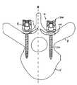
- FIG. 1is a transverse plane view of a spinal fixation device including a pedicle screw and an intralaminar hook placed within a vertebra;
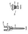
- FIG. 2is a front view of the pedicle screw of FIG. 1 ;
- FIG. 2Ais an enlarged view of detail A of the pedicle screw of FIG. 2
- FIG. 3is an isometric view of the intralaminar hook of FIG. 1 ;
- FIG. 4is an isometric view of the spinal fixation device of FIG. 1 ;
- FIG. 5is an isometric view of a spinal fixation device including a pedicle screw and a laminar hook affixed to a vertebra;
- FIG. 6is an isometric view of the laminar hook of FIG. 5 ;
- FIG. 7is an isometric view of the spinal fixation device of FIG. 5 ;
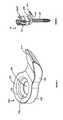
- FIG. 8is an isometric view of a spinal fixation device including a pedicle screw and a pedicle hook;
- FIG. 9is an isometric view of the pedicle hook of FIG. 8 ;
- FIG. 10is an isometric view of the spinal fixation device of FIG. 8 .
- proximalwill refer to the end of a device or system that is closest to the operator
- distalwill refer to the end of the device or system that is farthest from the operator.
- cephaladis used in this application to indicate a direction toward a patient's head
- the term “caudad”indicates a direction toward the patient's feet.
- the term “medial”indicates a direction toward a side of the body of the patient, i.e., away from the middle of the body of the patient.
- the term “posterior”indicates a direction toward the patient's back, and the term “anterior” indicates a direction toward the patient's front.
- the spinal fixation device 10includes an intralaminar hook 100 and a pedicle screw 200 .
- the intralaminar hook 100shown best in FIG. 3 , includes a bone anchor through hole 130 of sufficient size to receive a shank 201 of a pedicle screw 200 , shown in FIGS. 2-2A , and to provide an adequate seating surface for a head 221 of the pedicle screw 200 .
- the laminar hookfurther includes a curved protrusion 120 .
- the laminar hook 100is of a sufficient length to approach midline M of the vertebra V.
- the dimensions and orientation of the laminar hook 100may differ.
- An exemplary pedicle screw 200 including a shank 201 and a collet 70 , shown in FIG. 2may be of a rigid, unitary design or may be polyaxial. Examples of polyaxial screws are found in U.S. Pat. Nos. 5,733,286; 5,683,392; and 6,451,021, Published U.S. Patent Application 20080027432, and International Patent Applications Serial Nos. PCT/US08/80682 and PCT/US08/80668, the entire contents of which are incorporated herein by reference. In the exemplary polyaxial screw shown in FIG.
- the collet 70 of the pedicle screw 200is configured and dimensioned to receive head 221 of the shank 201 such that the collet 70 and the head 221 are rotatable and pivotable in relation to each other, thereby allowing the shank 201 to be repositioned in a plurality of orientations relative to the collet 70 .
- the shank 201optionally may have a dual pitch thread whereby proximal threads 220 have a different pitch than distal threads 210 , as shown in FIG. 2A .
- the distal threads 210are adapted for aggressive purchase in cancellous bone.
- the proximal threads 220have a finer pitch thread.
- the proximal threads 220may be removably or permanently fixed to an annular sidewall 131 of the bone anchor through hole 130 upon insertion of the pedicle screw 200 therethrough.
- Such a locking mechanismmay also be included on laminar hook 300 and pedicle hook 400 , described below.
- a screw locking mechanism of this typeis disclosed in U.S. Pat. No. 6,322,562, the entire contents of which are incorporated by reference.
- the bone anchor through hole 130has an annular sidewall 131 extending downward from a top surface 133 .
- a lip 132is located in the bone anchor through hole 130 in proximity to a bottom surface 134 .
- the lip 132is configured for engaging the proximal threads 220 of the shank 201 such that rotating the shank 201 causes the proximal threads 220 to engage the lip 132 such that the pedicle screw 200 is secured in the bone anchor through hole 130 and resists backing out of the bone anchor through hole 130 .
- the material of the intralaminar hook 100i.e. commercially pure titanium
- that of the pedicle screw 200i.e.
- proximal threads 220 of shank 201to engage the lip 132 as the shank 201 is inserted into the bone anchor through hole 130 and resists backing out of the bone anchor through hole 130 .
- the proximal threads 220engage the lip 132 when the pedicle screw 200 is in various angular orientations with respect to the axis of the bone anchor through hole 130 .
- pedicle screw 200may be secured to bone without the use of such a locking mechanism since the interaction of the pedicle screw 200 and one of intralaminar hook 100 , laminar hook 300 , and pedicle hook 400 would provide an adequate fixation point.
- Installation of the spinal fixation device 10is achieved by positioning the bone anchor through hole 130 over a pedicle P of a vertebra V and embedding the curved protrusion 120 of the intralaminar hook 100 within a lamina L of the vertebra V.
- a tapered end 110 of the curved protrusion 120may ease insertion of the curved protrusion into the lamina L.
- the screw shank 201is then driven through the bone anchor through hole 130 and into the pedicle P, thereby fixing the intralaminar hook 100 between the pedicle screw 200 and the pedicle P, as shown in FIG. 1 .
- a spinal rod R or plate(not shown) is affixable to the pedicle screw 200 .
- a spinal fixation device 20is shown in FIGS. 5-7 , including a laminar hook 300 and the pedicle screw construct 200 .
- the laminar hook 300includes a curved protrusion 310 to hook around and onto the lamina L, and a bone anchor through hole 330 to receive the pedicle screw 200 , as shown in FIG. 5 .
- the hookis shown hooked onto the superior edge surface of the lamina, but it is contemplated that the hook could be configured to hook onto the inferior edge surface of the lamina.
- the pedicle Pmay be prepared by making a pilot hole in the pedicle P using known instruments and techniques.
- the laminar hook 300is attached to a surface of the lamina L.
- the through hole 330is then placed over the pilot hole.
- the pedicle screw 200is then inserted through the through hole 330 and into the pilot hole and into the pedicle P.
- Optional proximal threads 220may lock with an optional annular sidewall 331 extending downward from a top surface 333 and lip 332 located in the through hole 330 in proximity to a bottom surface 334 and configured to engage the proximal threads 220 of the shank 201 ( FIG. 6 ), as discussed above with reference to intralaminar hook 100 .
- the spinal fixation device 20When the pedicle screw 200 is fully seated, the spinal fixation device 20 has two areas of fixation, one at the shank 201 positioned in the pedicle P and vertebral body V and the other where the spinal fixation device 20 is secured to the lamina L. A spinal rod R or a plate (not shown) may then be attached to the pedicle screw 200 .
- the spinal fixation device 30includes a pedicle hook 400 including a curved protrusion 420 that is anchorable to the pedicle and the pedicle screw construct 200 receivable within a bone anchor through hole 430 of the pedicle hook.
- Optional proximal threads 220are removably or permanently fixable to an annular sidewall 431 extending downward from a top surface 433 and optional lip 432 located in the through hole 430 in proximity to a bottom surface 434 and configured to engage the proximal threads 220 of the shank 201 , as previously described with respect to the intralaminar hook 100 .
- Installation of the spinal fixation device 30is achieved by making a pilot hole using known instruments and techniques in the pedicle P for receipt of the pedicle screw 200 and positioning the through hole 430 of the pedicle hook 400 over the pilot hole and positioning the pedicle hook 400 about a surface of the pedicle P.
- the pedicle hookis shown extends around the pedicle in the region of the inferior vertebral notch to provide enhanced stability and fixation of the pedicle screw.
- the pedicle hookcould be configured and dimensioned engage the area of the pedicle toward the superior vertebral notch.
- the hookcould be configured and dimensioned to penetrate a portion of the pedicle.
- the shank 201is inserted through the through hole 430 and into the pedicle P.
- the screw and fixation device 30has two areas of fixation, one at the shank 201 positioned in the pedicle P and vertebral body V and the other where the spinal fixation device 30 is secured to the pedicle P.
- a spinal rod R or a plate(not shown) is then attached to the pedicle screw 200 .
- any suitable bone anchormay be used.
- the dimensions, shapes, and orientations of the curved protrusions 120 , 320 , and 420may be modified to better fit a patient's unique anatomical characteristics while remaining within the spirit of the disclosure.
- the illustrationsshow the attachment device in the context of lumbar anatomy, it will be understood that the device could be configured and dimensioned for use in the cervical spine, thoracic spine, sacrum or other applications where supplemental fixation of a fastener in bone.
- the attachment portion of the attachment deviceneed not constitute a through hole, but could incompletely surround the screw shaft or other configuration provided the screw and attachment member suitably engage each other.
- other optional locking mechanisms to secure the screw to the attachment memberalso are contemplated, such as a compression ring, threads in the attachment member through hole to engage threads on the fastener, a floating or movable threaded ring in the through hole to engage threads on the fastener shaft, or a portion of the attachment member to engage a notch or opening in the screw shaft, etc.
- the threads on the fastener to engage the attachment membermay be on the fastener shaft or the fastener head.
Landscapes
- Health & Medical Sciences (AREA)
- Orthopedic Medicine & Surgery (AREA)
- Life Sciences & Earth Sciences (AREA)
- Neurology (AREA)
- Surgery (AREA)
- Heart & Thoracic Surgery (AREA)
- Engineering & Computer Science (AREA)
- Biomedical Technology (AREA)
- Nuclear Medicine, Radiotherapy & Molecular Imaging (AREA)
- Medical Informatics (AREA)
- Molecular Biology (AREA)
- Animal Behavior & Ethology (AREA)
- General Health & Medical Sciences (AREA)
- Public Health (AREA)
- Veterinary Medicine (AREA)
- Surgical Instruments (AREA)
Abstract
Description
Claims (12)
Priority Applications (1)
| Application Number | Priority Date | Filing Date | Title |
|---|---|---|---|
| US12/812,829US9622789B2 (en) | 2008-01-14 | 2009-01-12 | Spinal fixation device and method |
Applications Claiming Priority (3)
| Application Number | Priority Date | Filing Date | Title |
|---|---|---|---|
| US1101408P | 2008-01-14 | 2008-01-14 | |
| US12/812,829US9622789B2 (en) | 2008-01-14 | 2009-01-12 | Spinal fixation device and method |
| PCT/US2009/030721WO2009091689A1 (en) | 2008-01-14 | 2009-01-12 | Spinal fixation device and method |
Publications (2)
| Publication Number | Publication Date |
|---|---|
| US20100305616A1 US20100305616A1 (en) | 2010-12-02 |
| US9622789B2true US9622789B2 (en) | 2017-04-18 |
Family
ID=40885623
Family Applications (1)
| Application Number | Title | Priority Date | Filing Date |
|---|---|---|---|
| US12/812,829Active2029-09-30US9622789B2 (en) | 2008-01-14 | 2009-01-12 | Spinal fixation device and method |
Country Status (5)
| Country | Link |
|---|---|
| US (1) | US9622789B2 (en) |
| EP (1) | EP2249717B1 (en) |
| JP (1) | JP5583598B2 (en) |
| AU (2) | AU2009205575B2 (en) |
| WO (1) | WO2009091689A1 (en) |
Cited By (2)
| Publication number | Priority date | Publication date | Assignee | Title |
|---|---|---|---|---|
| US20200237411A1 (en)* | 2019-01-30 | 2020-07-30 | Medos International Sarl | Surgical device for spinal fixation |
| US20200390472A1 (en)* | 2019-02-27 | 2020-12-17 | Orthopediatrics Corp. | Bone anchor with cord retention features |
Families Citing this family (19)
| Publication number | Priority date | Publication date | Assignee | Title |
|---|---|---|---|---|
| US8790380B2 (en) | 2007-07-26 | 2014-07-29 | Dynamic Spine, Llc | Segmental orthopaedic device for spinal elongation and for treatment of scoliosis |
| US9204908B2 (en)* | 2007-07-26 | 2015-12-08 | Dynamic Spine, Llc | Segmental orthopedic device for spinal elongation and for treatment of scoliosis |
| AU2011264818B2 (en) | 2010-06-10 | 2015-06-18 | Globus Medical, Inc. | Low-profile, uniplanar bone screw |
| US9247962B2 (en) | 2011-08-15 | 2016-02-02 | K2M, Inc. | Laminar hook insertion device |
| US20130218208A1 (en)* | 2012-02-16 | 2013-08-22 | The Uab Research Foundation | Rod-receiving spinal fusion attachment elements |
| US20140277155A1 (en) | 2013-03-14 | 2014-09-18 | K2M, Inc. | Taper lock hook |
| WO2014146018A1 (en)* | 2013-03-15 | 2014-09-18 | Jcbd, Llc | Systems and methods for fusing a sacroiliac joint and anchoring an orthopedic appliance |
| US20150230828A1 (en) | 2014-02-20 | 2015-08-20 | K2M, Inc. | Spinal fixation device |
| WO2016028784A1 (en)* | 2014-08-19 | 2016-02-25 | Cronen Geoffrey | Circumferential vertebral column fixation system |
| DE102014117175A1 (en)* | 2014-11-24 | 2016-05-25 | Aesculap Ag | Pedicle screw system and spine stabilization system |
| US20160206358A1 (en)* | 2015-01-21 | 2016-07-21 | Chunfeng Zhao | Orthopedic Fixation System and Method |
| US9962192B2 (en) | 2016-03-17 | 2018-05-08 | Medos International Sarl | Multipoint fixation implants |
| US10898232B2 (en) | 2018-03-20 | 2021-01-26 | Medos International Sàrl | Multipoint fixation implants and related methods |
| US10517651B1 (en)* | 2018-11-12 | 2019-12-31 | Medlastics Llc | Facet joint compression system for spinal stabilization |
| US11510709B2 (en) | 2019-02-11 | 2022-11-29 | Carl P. Giordano | Methods and apparatus for treating spondylolysis |
| US11426210B2 (en) | 2019-09-25 | 2022-08-30 | Medos International Sàrl | Multipoint angled fixation implants for multiple screws and related methods |
| EP4103083B1 (en) | 2020-02-14 | 2024-10-23 | Medos International Sàrl | Integrated multipoint fixation screw |
| JP7407273B2 (en)* | 2020-04-03 | 2023-12-28 | 京セラ株式会社 | Spinal surgery instruments and systems |
| US11918259B2 (en)* | 2022-01-28 | 2024-03-05 | Carl P. Giordano | Methods and apparatus for treating spondylolysis |
Citations (29)
| Publication number | Priority date | Publication date | Assignee | Title |
|---|---|---|---|---|
| US5269784A (en)* | 1991-12-10 | 1993-12-14 | Synthes (U.S.A.) | Screw nut for plate osteosynthesis |
| WO1994000062A1 (en) | 1992-06-19 | 1994-01-06 | Pierre Roussouly | Spinal therapy apparatus |
| US5306275A (en)* | 1992-12-31 | 1994-04-26 | Bryan Donald W | Lumbar spine fixation apparatus and method |
| WO1994021186A1 (en) | 1993-03-15 | 1994-09-29 | Synthes Ag, Chur | Hook with bolt for treating spinal deformities |
| US5415659A (en)* | 1993-12-01 | 1995-05-16 | Amei Technologies Inc. | Spinal fixation system and pedicle clamp |
| US5507747A (en)* | 1994-03-09 | 1996-04-16 | Yuan; Hansen A. | Vertebral fixation device |
| JPH08336548A (en) | 1995-06-13 | 1996-12-24 | Mizuho Ika Kogyo Kk | Centrum screw of spine correcting device |
| US5611800A (en) | 1994-02-15 | 1997-03-18 | Alphatec Manufacturing, Inc. | Spinal fixation system |
| US5667506A (en) | 1992-10-22 | 1997-09-16 | Danek Medical, Inc. | Spinal rod transverse connector for supporting vertebral fixation elements |
| US5810816A (en)* | 1994-04-20 | 1998-09-22 | Roussouly; Pierre | Device for stabilizing orthopedic anchors |
| US6030162A (en)* | 1998-12-18 | 2000-02-29 | Acumed, Inc. | Axial tension screw |
| WO2000064365A1 (en) | 1999-04-23 | 2000-11-02 | Sdgi Holdings, Inc. | Shape memory alloy staple |
| US6261288B1 (en)* | 2000-02-08 | 2001-07-17 | Roger P. Jackson | Implant stabilization and locking system |
| US6322562B1 (en)* | 1998-12-19 | 2001-11-27 | Dietmar Wolter | Fixation system for bones |
| FR2813782A1 (en) | 2000-09-13 | 2002-03-15 | Eurosurgical | Ancillary fastening for spinal osteosynthesis apparatus has transverse link connecting pairs of anchoring screws and/or hooks |
| JP2002233532A (en) | 2001-01-05 | 2002-08-20 | Stryker Spine Sa | Assembly for fixing |
| US20040106925A1 (en)* | 2002-11-25 | 2004-06-03 | Culbert Brad S. | Soft tissue anchor and method of using same |
| US20040111091A1 (en)* | 2002-05-21 | 2004-06-10 | James Ogilvie | Reduction cable and bone anchor |
| US6749361B2 (en) | 1997-10-06 | 2004-06-15 | Werner Hermann | Shackle element for clamping a fixation rod, a method for making a shackle element, a hook with a shackle element and a rode connector with a shackle element |
| WO2004064654A1 (en) | 2002-12-17 | 2004-08-05 | Vitatech | Device comprising anterior plate for vertebral column support |
| US20040220570A1 (en) | 1998-05-19 | 2004-11-04 | Synthes (Usa) | Osteosynthetic implant with an embedded hinge joint |
| US20040260296A1 (en)* | 2003-06-18 | 2004-12-23 | Kaiser Ryan A. | Device and method of fastening a graft to a bone |
| WO2005032386A1 (en) | 2003-09-29 | 2005-04-14 | Smith & Nephew, Inc. | Bone plates with hole for interchangeably receiving locking and compression screws |
| US6974478B2 (en) | 1999-10-22 | 2005-12-13 | Archus Orthopedics, Inc. | Prostheses, systems and methods for replacement of natural facet joints with artificial facet joint surfaces |
| US20070213732A1 (en)* | 2006-03-13 | 2007-09-13 | The Johns Hopkins University | Orthopedic Screw System |
| WO2008060930A2 (en) | 2006-11-10 | 2008-05-22 | Warsaw Orthopedic, Inc. | Posterior fixation devices and methods of use |
| US20080255619A1 (en)* | 2007-04-10 | 2008-10-16 | Schneiderman Gary A | Posterior spinal fixation with colinear facet screw |
| US7635365B2 (en)* | 2003-08-28 | 2009-12-22 | Ellis Thomas J | Bone plates |
| US7645294B2 (en)* | 2004-03-31 | 2010-01-12 | Depuy Spine, Inc. | Head-to-head connector spinal fixation system |
Family Cites Families (4)
| Publication number | Priority date | Publication date | Assignee | Title |
|---|---|---|---|---|
| US5683392A (en) | 1995-10-17 | 1997-11-04 | Wright Medical Technology, Inc. | Multi-planar locking mechanism for bone fixation |
| US5733286A (en) | 1997-02-12 | 1998-03-31 | Third Millennium Engineering, Llc | Rod securing polyaxial locking screw and coupling element assembly |
| US6451021B1 (en) | 2001-02-15 | 2002-09-17 | Third Millennium Engineering, Llc | Polyaxial pedicle screw having a rotating locking element |
| US8162991B2 (en) | 2006-07-27 | 2012-04-24 | K2M, Inc. | Multi-planar, taper lock screw |
- 2009
- 2009-01-12EPEP09702226.3Apatent/EP2249717B1/ennot_activeNot-in-force
- 2009-01-12USUS12/812,829patent/US9622789B2/enactiveActive
- 2009-01-12WOPCT/US2009/030721patent/WO2009091689A1/enactiveApplication Filing
- 2009-01-12AUAU2009205575Apatent/AU2009205575B2/ennot_activeCeased
- 2009-01-12JPJP2010542399Apatent/JP5583598B2/ennot_activeExpired - Fee Related
- 2014
- 2014-07-10AUAU2014203776Apatent/AU2014203776B2/ennot_activeCeased
Patent Citations (33)
| Publication number | Priority date | Publication date | Assignee | Title |
|---|---|---|---|---|
| US5269784A (en)* | 1991-12-10 | 1993-12-14 | Synthes (U.S.A.) | Screw nut for plate osteosynthesis |
| WO1994000062A1 (en) | 1992-06-19 | 1994-01-06 | Pierre Roussouly | Spinal therapy apparatus |
| US5667506A (en) | 1992-10-22 | 1997-09-16 | Danek Medical, Inc. | Spinal rod transverse connector for supporting vertebral fixation elements |
| US5306275A (en)* | 1992-12-31 | 1994-04-26 | Bryan Donald W | Lumbar spine fixation apparatus and method |
| WO1994021186A1 (en) | 1993-03-15 | 1994-09-29 | Synthes Ag, Chur | Hook with bolt for treating spinal deformities |
| US5584832A (en)* | 1993-03-15 | 1996-12-17 | Synthes (U.S.A.) | Hook with screw for treatment of vertebral column deformities |
| US5415659A (en)* | 1993-12-01 | 1995-05-16 | Amei Technologies Inc. | Spinal fixation system and pedicle clamp |
| US5611800A (en) | 1994-02-15 | 1997-03-18 | Alphatec Manufacturing, Inc. | Spinal fixation system |
| US5507747A (en)* | 1994-03-09 | 1996-04-16 | Yuan; Hansen A. | Vertebral fixation device |
| US5810816A (en)* | 1994-04-20 | 1998-09-22 | Roussouly; Pierre | Device for stabilizing orthopedic anchors |
| JPH08336548A (en) | 1995-06-13 | 1996-12-24 | Mizuho Ika Kogyo Kk | Centrum screw of spine correcting device |
| US6749361B2 (en) | 1997-10-06 | 2004-06-15 | Werner Hermann | Shackle element for clamping a fixation rod, a method for making a shackle element, a hook with a shackle element and a rode connector with a shackle element |
| US20040220570A1 (en) | 1998-05-19 | 2004-11-04 | Synthes (Usa) | Osteosynthetic implant with an embedded hinge joint |
| US6030162A (en)* | 1998-12-18 | 2000-02-29 | Acumed, Inc. | Axial tension screw |
| US6322562B1 (en)* | 1998-12-19 | 2001-11-27 | Dietmar Wolter | Fixation system for bones |
| WO2000064365A1 (en) | 1999-04-23 | 2000-11-02 | Sdgi Holdings, Inc. | Shape memory alloy staple |
| US6974478B2 (en) | 1999-10-22 | 2005-12-13 | Archus Orthopedics, Inc. | Prostheses, systems and methods for replacement of natural facet joints with artificial facet joint surfaces |
| US6261288B1 (en)* | 2000-02-08 | 2001-07-17 | Roger P. Jackson | Implant stabilization and locking system |
| FR2813782A1 (en) | 2000-09-13 | 2002-03-15 | Eurosurgical | Ancillary fastening for spinal osteosynthesis apparatus has transverse link connecting pairs of anchoring screws and/or hooks |
| JP2002233532A (en) | 2001-01-05 | 2002-08-20 | Stryker Spine Sa | Assembly for fixing |
| US6488681B2 (en) | 2001-01-05 | 2002-12-03 | Stryker Spine S.A. | Pedicle screw assembly |
| US20040111091A1 (en)* | 2002-05-21 | 2004-06-10 | James Ogilvie | Reduction cable and bone anchor |
| US7338490B2 (en)* | 2002-05-21 | 2008-03-04 | Warsaw Orthopedic, Inc. | Reduction cable and bone anchor |
| US20040106925A1 (en)* | 2002-11-25 | 2004-06-03 | Culbert Brad S. | Soft tissue anchor and method of using same |
| US20060116676A1 (en) | 2002-12-17 | 2006-06-01 | Thomas Gradel | Device comprising anterior plate for vertebral column support |
| WO2004064654A1 (en) | 2002-12-17 | 2004-08-05 | Vitatech | Device comprising anterior plate for vertebral column support |
| US20040260296A1 (en)* | 2003-06-18 | 2004-12-23 | Kaiser Ryan A. | Device and method of fastening a graft to a bone |
| US7635365B2 (en)* | 2003-08-28 | 2009-12-22 | Ellis Thomas J | Bone plates |
| WO2005032386A1 (en) | 2003-09-29 | 2005-04-14 | Smith & Nephew, Inc. | Bone plates with hole for interchangeably receiving locking and compression screws |
| US7645294B2 (en)* | 2004-03-31 | 2010-01-12 | Depuy Spine, Inc. | Head-to-head connector spinal fixation system |
| US20070213732A1 (en)* | 2006-03-13 | 2007-09-13 | The Johns Hopkins University | Orthopedic Screw System |
| WO2008060930A2 (en) | 2006-11-10 | 2008-05-22 | Warsaw Orthopedic, Inc. | Posterior fixation devices and methods of use |
| US20080255619A1 (en)* | 2007-04-10 | 2008-10-16 | Schneiderman Gary A | Posterior spinal fixation with colinear facet screw |
Non-Patent Citations (5)
| Title |
|---|
| Australian Examination Report dated Oct. 10, 2016, issued in Australian Application No. 2014203776. |
| Australian Patent Examination Report for Application No. 200905575 dated Feb. 15, 2013 (3 pages). |
| European Examination Report dated Sep. 30, 2013 in European Application No. 09 702 226. |
| European Search Report dated Nov. 20, 2012 in copending European Patent Appln. No. 09 702 226. |
| Japanese Office Action dated Apr. 9, 2013 in counterpart Japanese Patent Application No. 2010-542399. |
Cited By (5)
| Publication number | Priority date | Publication date | Assignee | Title |
|---|---|---|---|---|
| US20200237411A1 (en)* | 2019-01-30 | 2020-07-30 | Medos International Sarl | Surgical device for spinal fixation |
| US10869696B2 (en)* | 2019-01-30 | 2020-12-22 | Medos International Sarl | Surgical device for spinal fixation |
| US11844552B2 (en) | 2019-01-30 | 2023-12-19 | Medos International Sarl | Surgical device for spinal fixation |
| US20200390472A1 (en)* | 2019-02-27 | 2020-12-17 | Orthopediatrics Corp. | Bone anchor with cord retention features |
| US12082848B2 (en)* | 2019-02-27 | 2024-09-10 | Orthopediatrics Corp. | Bone anchors with cord retention features |
Also Published As
| Publication number | Publication date |
|---|---|
| AU2014203776A1 (en) | 2014-07-31 |
| JP5583598B2 (en) | 2014-09-03 |
| EP2249717A1 (en) | 2010-11-17 |
| EP2249717B1 (en) | 2015-02-25 |
| JP2011509712A (en) | 2011-03-31 |
| EP2249717A4 (en) | 2012-12-19 |
| US20100305616A1 (en) | 2010-12-02 |
| AU2009205575A1 (en) | 2009-07-23 |
| WO2009091689A1 (en) | 2009-07-23 |
| AU2009205575B2 (en) | 2014-08-28 |
| AU2014203776B2 (en) | 2017-03-16 |
Similar Documents
| Publication | Publication Date | Title |
|---|---|---|
| US9622789B2 (en) | Spinal fixation device and method | |
| EP3366240B1 (en) | Spinal implant system | |
| US8623062B2 (en) | System and method to stablize a spinal column including a spinolaminar locking plate | |
| AU2011227073B2 (en) | Spinal fixation apparatus and methods | |
| US9220536B2 (en) | System and method for correction of a spinal disorder | |
| AU690179B2 (en) | Transverse link for spinal implant system | |
| US6533790B1 (en) | Self-guided pedical screw | |
| US20140243900A1 (en) | Iliosacral polyaxial screw | |
| US20150190186A1 (en) | Pedicle screw with reverse spiral cut and methods thereof | |
| WO1991016020A1 (en) | Transpedicular screw system and method of use | |
| EP3226789B1 (en) | Bone implant having tether band | |
| US9801662B2 (en) | Spinal stabilization system | |
| US20180049776A1 (en) | Spinal stabilization system | |
| US20090240291A1 (en) | Breached pedicle screw | |
| US9168068B2 (en) | Spinal stabilization system | |
| US11969192B2 (en) | Spinal implant system and method | |
| US9095378B2 (en) | Spinal stabilization system | |
| US8506598B1 (en) | Anchors for spinal fixation and correcting spinal deformity | |
| US12185997B2 (en) | Pedicle fixation system | |
| US20120245693A1 (en) | Spinal fixation device |
Legal Events
| Date | Code | Title | Description |
|---|---|---|---|
| AS | Assignment | Owner name:K2M, INC., VIRGINIA Free format text:ASSIGNMENT OF ASSIGNORS INTEREST;ASSIGNOR:CARBONE, JOHN;REEL/FRAME:024854/0608 Effective date:20100817 | |
| AS | Assignment | Owner name:SILICON VALLEY BANK, CALIFORNIA Free format text:ADDENDUM TO INTELLECTUAL PROPERTY SECURITY AGREEMENT;ASSIGNOR:K2M, INC.;REEL/FRAME:026565/0482 Effective date:20110629 | |
| AS | Assignment | Owner name:SILICON VALLEY BANK, MASSACHUSETTS Free format text:SECURITY INTEREST;ASSIGNORS:K2M, INC.;K2M HOLDING, INC.;K2M UK LIMITED;REEL/FRAME:029489/0327 Effective date:20121029 | |
| AS | Assignment | Owner name:K2M, INC., VIRGINIA Free format text:TERMINATION;ASSIGNOR:SILICON VALLEY BANK;REEL/FRAME:030918/0426 Effective date:20121029 | |
| AS | Assignment | Owner name:SILICON VALLEY BANK, CALIFORNIA Free format text:FIRST AMENDMENT TO PATENT SECURITY AGREEMENT;ASSIGNORS:K2M, INC.;K2M UNLIMITED;K2M HOLDINGS, INC.;REEL/FRAME:034034/0097 Effective date:20141021 | |
| STCF | Information on status: patent grant | Free format text:PATENTED CASE | |
| AS | Assignment | Owner name:K2M HOLDINGS, INC., VIRGINIA Free format text:RELEASE BY SECURED PARTY;ASSIGNOR:SILICON VALLEY BANK;REEL/FRAME:047496/0001 Effective date:20181109 Owner name:K2M UK LIMITED, UNITED KINGDOM Free format text:RELEASE BY SECURED PARTY;ASSIGNOR:SILICON VALLEY BANK;REEL/FRAME:047496/0001 Effective date:20181109 Owner name:K2M, INC., VIRGINIA Free format text:RELEASE BY SECURED PARTY;ASSIGNOR:SILICON VALLEY BANK;REEL/FRAME:047496/0001 Effective date:20181109 | |
| FEPP | Fee payment procedure | Free format text:ENTITY STATUS SET TO UNDISCOUNTED (ORIGINAL EVENT CODE: BIG.); ENTITY STATUS OF PATENT OWNER: LARGE ENTITY | |
| MAFP | Maintenance fee payment | Free format text:PAYMENT OF MAINTENANCE FEE, 4TH YEAR, LARGE ENTITY (ORIGINAL EVENT CODE: M1551); ENTITY STATUS OF PATENT OWNER: LARGE ENTITY Year of fee payment:4 | |
| MAFP | Maintenance fee payment | Free format text:PAYMENT OF MAINTENANCE FEE, 8TH YEAR, LARGE ENTITY (ORIGINAL EVENT CODE: M1552); ENTITY STATUS OF PATENT OWNER: LARGE ENTITY Year of fee payment:8 | |
| AS | Assignment | Owner name:STRYKER CORPORATION, MICHIGAN Free format text:ASSIGNMENT OF ASSIGNORS INTEREST;ASSIGNOR:K2M, INC.;REEL/FRAME:071271/0170 Effective date:20250328 | |
| AS | Assignment | Owner name:VB SPINE US OPCO LLC, DELAWARE Free format text:ASSIGNMENT OF ASSIGNORS INTEREST;ASSIGNOR:STRYKER CORPORATION;REEL/FRAME:071312/0356 Effective date:20250505 | |
| AS | Assignment | Owner name:ANKURA TRUST COMPANY, LLC, AS COLLATERAL AGENT, CONNECTICUT Free format text:PATENT SECURITY AGREEMENT;ASSIGNORS:K2M, INC.;VB SPINE US OPCO LLC;VB SPINE LLC;REEL/FRAME:071682/0116 Effective date:20250616 |