US9622783B2 - Systems and methods for the fixation or fusion of bone - Google Patents
Systems and methods for the fixation or fusion of boneDownload PDFInfo
- Publication number
- US9622783B2 US9622783B2US12/930,791US93079111AUS9622783B2US 9622783 B2US9622783 B2US 9622783B2US 93079111 AUS93079111 AUS 93079111AUS 9622783 B2US9622783 B2US 9622783B2
- Authority
- US
- United States
- Prior art keywords
- bone
- fixation
- fusion
- fusion device
- ridges
- Prior art date
- Legal status (The legal status is an assumption and is not a legal conclusion. Google has not performed a legal analysis and makes no representation as to the accuracy of the status listed.)
- Expired - Fee Related, expires
Links
Images


Classifications
- A—HUMAN NECESSITIES
- A61—MEDICAL OR VETERINARY SCIENCE; HYGIENE
- A61B—DIAGNOSIS; SURGERY; IDENTIFICATION
- A61B17/00—Surgical instruments, devices or methods
- A61B17/56—Surgical instruments or methods for treatment of bones or joints; Devices specially adapted therefor
- A61B17/58—Surgical instruments or methods for treatment of bones or joints; Devices specially adapted therefor for osteosynthesis, e.g. bone plates, screws or setting implements
- A61B17/68—Internal fixation devices, including fasteners and spinal fixators, even if a part thereof projects from the skin
- A61B17/72—Intramedullary devices, e.g. pins or nails
- A—HUMAN NECESSITIES
- A61—MEDICAL OR VETERINARY SCIENCE; HYGIENE
- A61B—DIAGNOSIS; SURGERY; IDENTIFICATION
- A61B17/00—Surgical instruments, devices or methods
- A61B17/56—Surgical instruments or methods for treatment of bones or joints; Devices specially adapted therefor
- A61B17/58—Surgical instruments or methods for treatment of bones or joints; Devices specially adapted therefor for osteosynthesis, e.g. bone plates, screws or setting implements
- A61B17/68—Internal fixation devices, including fasteners and spinal fixators, even if a part thereof projects from the skin
- A—HUMAN NECESSITIES
- A61—MEDICAL OR VETERINARY SCIENCE; HYGIENE
- A61B—DIAGNOSIS; SURGERY; IDENTIFICATION
- A61B17/00—Surgical instruments, devices or methods
- A61B17/16—Instruments for performing osteoclasis; Drills or chisels for bones; Trepans
- A61B17/1613—Component parts
- A61B17/1615—Drill bits, i.e. rotating tools extending from a handpiece to contact the worked material
- A—HUMAN NECESSITIES
- A61—MEDICAL OR VETERINARY SCIENCE; HYGIENE
- A61B—DIAGNOSIS; SURGERY; IDENTIFICATION
- A61B17/00—Surgical instruments, devices or methods
- A61B17/16—Instruments for performing osteoclasis; Drills or chisels for bones; Trepans
- A61B17/1662—Instruments for performing osteoclasis; Drills or chisels for bones; Trepans for particular parts of the body
- A61B17/1671—Instruments for performing osteoclasis; Drills or chisels for bones; Trepans for particular parts of the body for the spine
- A—HUMAN NECESSITIES
- A61—MEDICAL OR VETERINARY SCIENCE; HYGIENE
- A61B—DIAGNOSIS; SURGERY; IDENTIFICATION
- A61B17/00—Surgical instruments, devices or methods
- A61B17/16—Instruments for performing osteoclasis; Drills or chisels for bones; Trepans
- A61B17/1662—Instruments for performing osteoclasis; Drills or chisels for bones; Trepans for particular parts of the body
- A61B17/1682—Instruments for performing osteoclasis; Drills or chisels for bones; Trepans for particular parts of the body for the foot or ankle
- A—HUMAN NECESSITIES
- A61—MEDICAL OR VETERINARY SCIENCE; HYGIENE
- A61B—DIAGNOSIS; SURGERY; IDENTIFICATION
- A61B17/00—Surgical instruments, devices or methods
- A61B17/56—Surgical instruments or methods for treatment of bones or joints; Devices specially adapted therefor
- A—HUMAN NECESSITIES
- A61—MEDICAL OR VETERINARY SCIENCE; HYGIENE
- A61B—DIAGNOSIS; SURGERY; IDENTIFICATION
- A61B17/00—Surgical instruments, devices or methods
- A61B17/56—Surgical instruments or methods for treatment of bones or joints; Devices specially adapted therefor
- A61B17/58—Surgical instruments or methods for treatment of bones or joints; Devices specially adapted therefor for osteosynthesis, e.g. bone plates, screws or setting implements
- A61B17/68—Internal fixation devices, including fasteners and spinal fixators, even if a part thereof projects from the skin
- A61B17/84—Fasteners therefor or fasteners being internal fixation devices
- A61B17/86—Pins or screws or threaded wires; nuts therefor
- A61B17/866—Material or manufacture
- A—HUMAN NECESSITIES
- A61—MEDICAL OR VETERINARY SCIENCE; HYGIENE
- A61B—DIAGNOSIS; SURGERY; IDENTIFICATION
- A61B17/00—Surgical instruments, devices or methods
- A61B17/56—Surgical instruments or methods for treatment of bones or joints; Devices specially adapted therefor
- A61B17/58—Surgical instruments or methods for treatment of bones or joints; Devices specially adapted therefor for osteosynthesis, e.g. bone plates, screws or setting implements
- A61B17/68—Internal fixation devices, including fasteners and spinal fixators, even if a part thereof projects from the skin
- A61B17/84—Fasteners therefor or fasteners being internal fixation devices
- A61B17/86—Pins or screws or threaded wires; nuts therefor
- A61B17/8685—Pins or screws or threaded wires; nuts therefor comprising multiple separate parts
- A—HUMAN NECESSITIES
- A61—MEDICAL OR VETERINARY SCIENCE; HYGIENE
- A61F—FILTERS IMPLANTABLE INTO BLOOD VESSELS; PROSTHESES; DEVICES PROVIDING PATENCY TO, OR PREVENTING COLLAPSING OF, TUBULAR STRUCTURES OF THE BODY, e.g. STENTS; ORTHOPAEDIC, NURSING OR CONTRACEPTIVE DEVICES; FOMENTATION; TREATMENT OR PROTECTION OF EYES OR EARS; BANDAGES, DRESSINGS OR ABSORBENT PADS; FIRST-AID KITS
- A61F2/00—Filters implantable into blood vessels; Prostheses, i.e. artificial substitutes or replacements for parts of the body; Appliances for connecting them with the body; Devices providing patency to, or preventing collapsing of, tubular structures of the body, e.g. stents
- A61F2/02—Prostheses implantable into the body
- A61F2/30—Joints
- A61F2/30767—Special external or bone-contacting surface, e.g. coating for improving bone ingrowth
- A61F2/30771—Special external or bone-contacting surface, e.g. coating for improving bone ingrowth applied in original prostheses, e.g. holes or grooves
- A—HUMAN NECESSITIES
- A61—MEDICAL OR VETERINARY SCIENCE; HYGIENE
- A61F—FILTERS IMPLANTABLE INTO BLOOD VESSELS; PROSTHESES; DEVICES PROVIDING PATENCY TO, OR PREVENTING COLLAPSING OF, TUBULAR STRUCTURES OF THE BODY, e.g. STENTS; ORTHOPAEDIC, NURSING OR CONTRACEPTIVE DEVICES; FOMENTATION; TREATMENT OR PROTECTION OF EYES OR EARS; BANDAGES, DRESSINGS OR ABSORBENT PADS; FIRST-AID KITS
- A61F2/00—Filters implantable into blood vessels; Prostheses, i.e. artificial substitutes or replacements for parts of the body; Appliances for connecting them with the body; Devices providing patency to, or preventing collapsing of, tubular structures of the body, e.g. stents
- A61F2/02—Prostheses implantable into the body
- A61F2/30—Joints
- A61F2/42—Joints for wrists or ankles; for hands, e.g. fingers; for feet, e.g. toes
- A61F2/4225—Joints for wrists or ankles; for hands, e.g. fingers; for feet, e.g. toes for feet, e.g. toes
- A—HUMAN NECESSITIES
- A61—MEDICAL OR VETERINARY SCIENCE; HYGIENE
- A61F—FILTERS IMPLANTABLE INTO BLOOD VESSELS; PROSTHESES; DEVICES PROVIDING PATENCY TO, OR PREVENTING COLLAPSING OF, TUBULAR STRUCTURES OF THE BODY, e.g. STENTS; ORTHOPAEDIC, NURSING OR CONTRACEPTIVE DEVICES; FOMENTATION; TREATMENT OR PROTECTION OF EYES OR EARS; BANDAGES, DRESSINGS OR ABSORBENT PADS; FIRST-AID KITS
- A61F2/00—Filters implantable into blood vessels; Prostheses, i.e. artificial substitutes or replacements for parts of the body; Appliances for connecting them with the body; Devices providing patency to, or preventing collapsing of, tubular structures of the body, e.g. stents
- A61F2/02—Prostheses implantable into the body
- A61F2/30—Joints
- A61F2/44—Joints for the spine, e.g. vertebrae, spinal discs
- A61F2/4455—Joints for the spine, e.g. vertebrae, spinal discs for the fusion of spinal bodies, e.g. intervertebral fusion of adjacent spinal bodies, e.g. fusion cages
- A—HUMAN NECESSITIES
- A61—MEDICAL OR VETERINARY SCIENCE; HYGIENE
- A61B—DIAGNOSIS; SURGERY; IDENTIFICATION
- A61B17/00—Surgical instruments, devices or methods
- A61B17/56—Surgical instruments or methods for treatment of bones or joints; Devices specially adapted therefor
- A61B17/58—Surgical instruments or methods for treatment of bones or joints; Devices specially adapted therefor for osteosynthesis, e.g. bone plates, screws or setting implements
- A61B17/68—Internal fixation devices, including fasteners and spinal fixators, even if a part thereof projects from the skin
- A61B17/84—Fasteners therefor or fasteners being internal fixation devices
- A61B17/86—Pins or screws or threaded wires; nuts therefor
- A61B17/864—Pins or screws or threaded wires; nuts therefor hollow, e.g. with socket or cannulated
- A—HUMAN NECESSITIES
- A61—MEDICAL OR VETERINARY SCIENCE; HYGIENE
- A61B—DIAGNOSIS; SURGERY; IDENTIFICATION
- A61B17/00—Surgical instruments, devices or methods
- A61B17/56—Surgical instruments or methods for treatment of bones or joints; Devices specially adapted therefor
- A61B2017/564—Methods for bone or joint treatment
- A—HUMAN NECESSITIES
- A61—MEDICAL OR VETERINARY SCIENCE; HYGIENE
- A61F—FILTERS IMPLANTABLE INTO BLOOD VESSELS; PROSTHESES; DEVICES PROVIDING PATENCY TO, OR PREVENTING COLLAPSING OF, TUBULAR STRUCTURES OF THE BODY, e.g. STENTS; ORTHOPAEDIC, NURSING OR CONTRACEPTIVE DEVICES; FOMENTATION; TREATMENT OR PROTECTION OF EYES OR EARS; BANDAGES, DRESSINGS OR ABSORBENT PADS; FIRST-AID KITS
- A61F2/00—Filters implantable into blood vessels; Prostheses, i.e. artificial substitutes or replacements for parts of the body; Appliances for connecting them with the body; Devices providing patency to, or preventing collapsing of, tubular structures of the body, e.g. stents
- A61F2/0077—Special surfaces of prostheses, e.g. for improving ingrowth
- A—HUMAN NECESSITIES
- A61—MEDICAL OR VETERINARY SCIENCE; HYGIENE
- A61F—FILTERS IMPLANTABLE INTO BLOOD VESSELS; PROSTHESES; DEVICES PROVIDING PATENCY TO, OR PREVENTING COLLAPSING OF, TUBULAR STRUCTURES OF THE BODY, e.g. STENTS; ORTHOPAEDIC, NURSING OR CONTRACEPTIVE DEVICES; FOMENTATION; TREATMENT OR PROTECTION OF EYES OR EARS; BANDAGES, DRESSINGS OR ABSORBENT PADS; FIRST-AID KITS
- A61F2/00—Filters implantable into blood vessels; Prostheses, i.e. artificial substitutes or replacements for parts of the body; Appliances for connecting them with the body; Devices providing patency to, or preventing collapsing of, tubular structures of the body, e.g. stents
- A61F2/02—Prostheses implantable into the body
- A61F2/28—Bones
- A—HUMAN NECESSITIES
- A61—MEDICAL OR VETERINARY SCIENCE; HYGIENE
- A61F—FILTERS IMPLANTABLE INTO BLOOD VESSELS; PROSTHESES; DEVICES PROVIDING PATENCY TO, OR PREVENTING COLLAPSING OF, TUBULAR STRUCTURES OF THE BODY, e.g. STENTS; ORTHOPAEDIC, NURSING OR CONTRACEPTIVE DEVICES; FOMENTATION; TREATMENT OR PROTECTION OF EYES OR EARS; BANDAGES, DRESSINGS OR ABSORBENT PADS; FIRST-AID KITS
- A61F2/00—Filters implantable into blood vessels; Prostheses, i.e. artificial substitutes or replacements for parts of the body; Appliances for connecting them with the body; Devices providing patency to, or preventing collapsing of, tubular structures of the body, e.g. stents
- A61F2/02—Prostheses implantable into the body
- A61F2/30—Joints
- A61F2/30767—Special external or bone-contacting surface, e.g. coating for improving bone ingrowth
- A—HUMAN NECESSITIES
- A61—MEDICAL OR VETERINARY SCIENCE; HYGIENE
- A61F—FILTERS IMPLANTABLE INTO BLOOD VESSELS; PROSTHESES; DEVICES PROVIDING PATENCY TO, OR PREVENTING COLLAPSING OF, TUBULAR STRUCTURES OF THE BODY, e.g. STENTS; ORTHOPAEDIC, NURSING OR CONTRACEPTIVE DEVICES; FOMENTATION; TREATMENT OR PROTECTION OF EYES OR EARS; BANDAGES, DRESSINGS OR ABSORBENT PADS; FIRST-AID KITS
- A61F2/00—Filters implantable into blood vessels; Prostheses, i.e. artificial substitutes or replacements for parts of the body; Appliances for connecting them with the body; Devices providing patency to, or preventing collapsing of, tubular structures of the body, e.g. stents
- A61F2/02—Prostheses implantable into the body
- A61F2/30—Joints
- A61F2/44—Joints for the spine, e.g. vertebrae, spinal discs
- A61F2/4455—Joints for the spine, e.g. vertebrae, spinal discs for the fusion of spinal bodies, e.g. intervertebral fusion of adjacent spinal bodies, e.g. fusion cages
- A61F2/4465—Joints for the spine, e.g. vertebrae, spinal discs for the fusion of spinal bodies, e.g. intervertebral fusion of adjacent spinal bodies, e.g. fusion cages having a circular or kidney shaped cross-section substantially perpendicular to the axis of the spine
- A—HUMAN NECESSITIES
- A61—MEDICAL OR VETERINARY SCIENCE; HYGIENE
- A61F—FILTERS IMPLANTABLE INTO BLOOD VESSELS; PROSTHESES; DEVICES PROVIDING PATENCY TO, OR PREVENTING COLLAPSING OF, TUBULAR STRUCTURES OF THE BODY, e.g. STENTS; ORTHOPAEDIC, NURSING OR CONTRACEPTIVE DEVICES; FOMENTATION; TREATMENT OR PROTECTION OF EYES OR EARS; BANDAGES, DRESSINGS OR ABSORBENT PADS; FIRST-AID KITS
- A61F2/00—Filters implantable into blood vessels; Prostheses, i.e. artificial substitutes or replacements for parts of the body; Appliances for connecting them with the body; Devices providing patency to, or preventing collapsing of, tubular structures of the body, e.g. stents
- A61F2/02—Prostheses implantable into the body
- A61F2/30—Joints
- A61F2/44—Joints for the spine, e.g. vertebrae, spinal discs
- A61F2/4455—Joints for the spine, e.g. vertebrae, spinal discs for the fusion of spinal bodies, e.g. intervertebral fusion of adjacent spinal bodies, e.g. fusion cages
- A61F2/447—Joints for the spine, e.g. vertebrae, spinal discs for the fusion of spinal bodies, e.g. intervertebral fusion of adjacent spinal bodies, e.g. fusion cages substantially parallelepipedal, e.g. having a rectangular or trapezoidal cross-section
- A—HUMAN NECESSITIES
- A61—MEDICAL OR VETERINARY SCIENCE; HYGIENE
- A61F—FILTERS IMPLANTABLE INTO BLOOD VESSELS; PROSTHESES; DEVICES PROVIDING PATENCY TO, OR PREVENTING COLLAPSING OF, TUBULAR STRUCTURES OF THE BODY, e.g. STENTS; ORTHOPAEDIC, NURSING OR CONTRACEPTIVE DEVICES; FOMENTATION; TREATMENT OR PROTECTION OF EYES OR EARS; BANDAGES, DRESSINGS OR ABSORBENT PADS; FIRST-AID KITS
- A61F2/00—Filters implantable into blood vessels; Prostheses, i.e. artificial substitutes or replacements for parts of the body; Appliances for connecting them with the body; Devices providing patency to, or preventing collapsing of, tubular structures of the body, e.g. stents
- A61F2/02—Prostheses implantable into the body
- A61F2/30—Joints
- A61F2002/30001—Additional features of subject-matter classified in A61F2/28, A61F2/30 and subgroups thereof
- A61F2002/30003—Material related properties of the prosthesis or of a coating on the prosthesis
- A61F2002/3006—Properties of materials and coating materials
- A61F2002/30062—(bio)absorbable, biodegradable, bioerodable, (bio)resorbable, resorptive
- A—HUMAN NECESSITIES
- A61—MEDICAL OR VETERINARY SCIENCE; HYGIENE
- A61F—FILTERS IMPLANTABLE INTO BLOOD VESSELS; PROSTHESES; DEVICES PROVIDING PATENCY TO, OR PREVENTING COLLAPSING OF, TUBULAR STRUCTURES OF THE BODY, e.g. STENTS; ORTHOPAEDIC, NURSING OR CONTRACEPTIVE DEVICES; FOMENTATION; TREATMENT OR PROTECTION OF EYES OR EARS; BANDAGES, DRESSINGS OR ABSORBENT PADS; FIRST-AID KITS
- A61F2/00—Filters implantable into blood vessels; Prostheses, i.e. artificial substitutes or replacements for parts of the body; Appliances for connecting them with the body; Devices providing patency to, or preventing collapsing of, tubular structures of the body, e.g. stents
- A61F2/02—Prostheses implantable into the body
- A61F2/30—Joints
- A61F2002/30001—Additional features of subject-matter classified in A61F2/28, A61F2/30 and subgroups thereof
- A61F2002/30108—Shapes
- A61F2002/3011—Cross-sections or two-dimensional shapes
- A61F2002/30138—Convex polygonal shapes
- A61F2002/30153—Convex polygonal shapes rectangular
- A—HUMAN NECESSITIES
- A61—MEDICAL OR VETERINARY SCIENCE; HYGIENE
- A61F—FILTERS IMPLANTABLE INTO BLOOD VESSELS; PROSTHESES; DEVICES PROVIDING PATENCY TO, OR PREVENTING COLLAPSING OF, TUBULAR STRUCTURES OF THE BODY, e.g. STENTS; ORTHOPAEDIC, NURSING OR CONTRACEPTIVE DEVICES; FOMENTATION; TREATMENT OR PROTECTION OF EYES OR EARS; BANDAGES, DRESSINGS OR ABSORBENT PADS; FIRST-AID KITS
- A61F2/00—Filters implantable into blood vessels; Prostheses, i.e. artificial substitutes or replacements for parts of the body; Appliances for connecting them with the body; Devices providing patency to, or preventing collapsing of, tubular structures of the body, e.g. stents
- A61F2/02—Prostheses implantable into the body
- A61F2/30—Joints
- A61F2002/30001—Additional features of subject-matter classified in A61F2/28, A61F2/30 and subgroups thereof
- A61F2002/30108—Shapes
- A61F2002/3011—Cross-sections or two-dimensional shapes
- A61F2002/30138—Convex polygonal shapes
- A61F2002/30156—Convex polygonal shapes triangular
- A—HUMAN NECESSITIES
- A61—MEDICAL OR VETERINARY SCIENCE; HYGIENE
- A61F—FILTERS IMPLANTABLE INTO BLOOD VESSELS; PROSTHESES; DEVICES PROVIDING PATENCY TO, OR PREVENTING COLLAPSING OF, TUBULAR STRUCTURES OF THE BODY, e.g. STENTS; ORTHOPAEDIC, NURSING OR CONTRACEPTIVE DEVICES; FOMENTATION; TREATMENT OR PROTECTION OF EYES OR EARS; BANDAGES, DRESSINGS OR ABSORBENT PADS; FIRST-AID KITS
- A61F2/00—Filters implantable into blood vessels; Prostheses, i.e. artificial substitutes or replacements for parts of the body; Appliances for connecting them with the body; Devices providing patency to, or preventing collapsing of, tubular structures of the body, e.g. stents
- A61F2/02—Prostheses implantable into the body
- A61F2/30—Joints
- A61F2002/30001—Additional features of subject-matter classified in A61F2/28, A61F2/30 and subgroups thereof
- A61F2002/30108—Shapes
- A61F2002/3011—Cross-sections or two-dimensional shapes
- A61F2002/30159—Concave polygonal shapes
- A61F2002/30179—X-shaped
- A—HUMAN NECESSITIES
- A61—MEDICAL OR VETERINARY SCIENCE; HYGIENE
- A61F—FILTERS IMPLANTABLE INTO BLOOD VESSELS; PROSTHESES; DEVICES PROVIDING PATENCY TO, OR PREVENTING COLLAPSING OF, TUBULAR STRUCTURES OF THE BODY, e.g. STENTS; ORTHOPAEDIC, NURSING OR CONTRACEPTIVE DEVICES; FOMENTATION; TREATMENT OR PROTECTION OF EYES OR EARS; BANDAGES, DRESSINGS OR ABSORBENT PADS; FIRST-AID KITS
- A61F2/00—Filters implantable into blood vessels; Prostheses, i.e. artificial substitutes or replacements for parts of the body; Appliances for connecting them with the body; Devices providing patency to, or preventing collapsing of, tubular structures of the body, e.g. stents
- A61F2/02—Prostheses implantable into the body
- A61F2/30—Joints
- A61F2002/30001—Additional features of subject-matter classified in A61F2/28, A61F2/30 and subgroups thereof
- A61F2002/30108—Shapes
- A61F2002/30199—Three-dimensional shapes
- A61F2002/30224—Three-dimensional shapes cylindrical
- A61F2002/3023—Three-dimensional shapes cylindrical wedge-shaped cylinders
- A—HUMAN NECESSITIES
- A61—MEDICAL OR VETERINARY SCIENCE; HYGIENE
- A61F—FILTERS IMPLANTABLE INTO BLOOD VESSELS; PROSTHESES; DEVICES PROVIDING PATENCY TO, OR PREVENTING COLLAPSING OF, TUBULAR STRUCTURES OF THE BODY, e.g. STENTS; ORTHOPAEDIC, NURSING OR CONTRACEPTIVE DEVICES; FOMENTATION; TREATMENT OR PROTECTION OF EYES OR EARS; BANDAGES, DRESSINGS OR ABSORBENT PADS; FIRST-AID KITS
- A61F2/00—Filters implantable into blood vessels; Prostheses, i.e. artificial substitutes or replacements for parts of the body; Appliances for connecting them with the body; Devices providing patency to, or preventing collapsing of, tubular structures of the body, e.g. stents
- A61F2/02—Prostheses implantable into the body
- A61F2/30—Joints
- A61F2002/30001—Additional features of subject-matter classified in A61F2/28, A61F2/30 and subgroups thereof
- A61F2002/30108—Shapes
- A61F2002/30199—Three-dimensional shapes
- A61F2002/30224—Three-dimensional shapes cylindrical
- A61F2002/30235—Three-dimensional shapes cylindrical tubular, e.g. sleeves
- A—HUMAN NECESSITIES
- A61—MEDICAL OR VETERINARY SCIENCE; HYGIENE
- A61F—FILTERS IMPLANTABLE INTO BLOOD VESSELS; PROSTHESES; DEVICES PROVIDING PATENCY TO, OR PREVENTING COLLAPSING OF, TUBULAR STRUCTURES OF THE BODY, e.g. STENTS; ORTHOPAEDIC, NURSING OR CONTRACEPTIVE DEVICES; FOMENTATION; TREATMENT OR PROTECTION OF EYES OR EARS; BANDAGES, DRESSINGS OR ABSORBENT PADS; FIRST-AID KITS
- A61F2/00—Filters implantable into blood vessels; Prostheses, i.e. artificial substitutes or replacements for parts of the body; Appliances for connecting them with the body; Devices providing patency to, or preventing collapsing of, tubular structures of the body, e.g. stents
- A61F2/02—Prostheses implantable into the body
- A61F2/30—Joints
- A61F2002/30001—Additional features of subject-matter classified in A61F2/28, A61F2/30 and subgroups thereof
- A61F2002/30316—The prosthesis having different structural features at different locations within the same prosthesis; Connections between prosthetic parts; Special structural features of bone or joint prostheses not otherwise provided for
- A61F2002/30329—Connections or couplings between prosthetic parts, e.g. between modular parts; Connecting elements
- A61F2002/30405—Connections or couplings between prosthetic parts, e.g. between modular parts; Connecting elements made by screwing complementary threads machined on the parts themselves
- A—HUMAN NECESSITIES
- A61—MEDICAL OR VETERINARY SCIENCE; HYGIENE
- A61F—FILTERS IMPLANTABLE INTO BLOOD VESSELS; PROSTHESES; DEVICES PROVIDING PATENCY TO, OR PREVENTING COLLAPSING OF, TUBULAR STRUCTURES OF THE BODY, e.g. STENTS; ORTHOPAEDIC, NURSING OR CONTRACEPTIVE DEVICES; FOMENTATION; TREATMENT OR PROTECTION OF EYES OR EARS; BANDAGES, DRESSINGS OR ABSORBENT PADS; FIRST-AID KITS
- A61F2/00—Filters implantable into blood vessels; Prostheses, i.e. artificial substitutes or replacements for parts of the body; Appliances for connecting them with the body; Devices providing patency to, or preventing collapsing of, tubular structures of the body, e.g. stents
- A61F2/02—Prostheses implantable into the body
- A61F2/30—Joints
- A61F2002/30001—Additional features of subject-matter classified in A61F2/28, A61F2/30 and subgroups thereof
- A61F2002/30316—The prosthesis having different structural features at different locations within the same prosthesis; Connections between prosthetic parts; Special structural features of bone or joint prostheses not otherwise provided for
- A61F2002/30329—Connections or couplings between prosthetic parts, e.g. between modular parts; Connecting elements
- A61F2002/30476—Connections or couplings between prosthetic parts, e.g. between modular parts; Connecting elements locked by an additional locking mechanism
- A61F2002/305—Snap connection
- A—HUMAN NECESSITIES
- A61—MEDICAL OR VETERINARY SCIENCE; HYGIENE
- A61F—FILTERS IMPLANTABLE INTO BLOOD VESSELS; PROSTHESES; DEVICES PROVIDING PATENCY TO, OR PREVENTING COLLAPSING OF, TUBULAR STRUCTURES OF THE BODY, e.g. STENTS; ORTHOPAEDIC, NURSING OR CONTRACEPTIVE DEVICES; FOMENTATION; TREATMENT OR PROTECTION OF EYES OR EARS; BANDAGES, DRESSINGS OR ABSORBENT PADS; FIRST-AID KITS
- A61F2/00—Filters implantable into blood vessels; Prostheses, i.e. artificial substitutes or replacements for parts of the body; Appliances for connecting them with the body; Devices providing patency to, or preventing collapsing of, tubular structures of the body, e.g. stents
- A61F2/02—Prostheses implantable into the body
- A61F2/30—Joints
- A61F2002/30001—Additional features of subject-matter classified in A61F2/28, A61F2/30 and subgroups thereof
- A61F2002/30316—The prosthesis having different structural features at different locations within the same prosthesis; Connections between prosthetic parts; Special structural features of bone or joint prostheses not otherwise provided for
- A61F2002/30535—Special structural features of bone or joint prostheses not otherwise provided for
- A61F2002/30576—Special structural features of bone or joint prostheses not otherwise provided for with extending fixation tabs
- A—HUMAN NECESSITIES
- A61—MEDICAL OR VETERINARY SCIENCE; HYGIENE
- A61F—FILTERS IMPLANTABLE INTO BLOOD VESSELS; PROSTHESES; DEVICES PROVIDING PATENCY TO, OR PREVENTING COLLAPSING OF, TUBULAR STRUCTURES OF THE BODY, e.g. STENTS; ORTHOPAEDIC, NURSING OR CONTRACEPTIVE DEVICES; FOMENTATION; TREATMENT OR PROTECTION OF EYES OR EARS; BANDAGES, DRESSINGS OR ABSORBENT PADS; FIRST-AID KITS
- A61F2/00—Filters implantable into blood vessels; Prostheses, i.e. artificial substitutes or replacements for parts of the body; Appliances for connecting them with the body; Devices providing patency to, or preventing collapsing of, tubular structures of the body, e.g. stents
- A61F2/02—Prostheses implantable into the body
- A61F2/30—Joints
- A61F2002/30001—Additional features of subject-matter classified in A61F2/28, A61F2/30 and subgroups thereof
- A61F2002/30316—The prosthesis having different structural features at different locations within the same prosthesis; Connections between prosthetic parts; Special structural features of bone or joint prostheses not otherwise provided for
- A61F2002/30535—Special structural features of bone or joint prostheses not otherwise provided for
- A61F2002/30604—Special structural features of bone or joint prostheses not otherwise provided for modular
- A—HUMAN NECESSITIES
- A61—MEDICAL OR VETERINARY SCIENCE; HYGIENE
- A61F—FILTERS IMPLANTABLE INTO BLOOD VESSELS; PROSTHESES; DEVICES PROVIDING PATENCY TO, OR PREVENTING COLLAPSING OF, TUBULAR STRUCTURES OF THE BODY, e.g. STENTS; ORTHOPAEDIC, NURSING OR CONTRACEPTIVE DEVICES; FOMENTATION; TREATMENT OR PROTECTION OF EYES OR EARS; BANDAGES, DRESSINGS OR ABSORBENT PADS; FIRST-AID KITS
- A61F2/00—Filters implantable into blood vessels; Prostheses, i.e. artificial substitutes or replacements for parts of the body; Appliances for connecting them with the body; Devices providing patency to, or preventing collapsing of, tubular structures of the body, e.g. stents
- A61F2/02—Prostheses implantable into the body
- A61F2/30—Joints
- A61F2002/30001—Additional features of subject-matter classified in A61F2/28, A61F2/30 and subgroups thereof
- A61F2002/30621—Features concerning the anatomical functioning or articulation of the prosthetic joint
- A61F2002/30622—Implant for fusing a joint or bone material
- A—HUMAN NECESSITIES
- A61—MEDICAL OR VETERINARY SCIENCE; HYGIENE
- A61F—FILTERS IMPLANTABLE INTO BLOOD VESSELS; PROSTHESES; DEVICES PROVIDING PATENCY TO, OR PREVENTING COLLAPSING OF, TUBULAR STRUCTURES OF THE BODY, e.g. STENTS; ORTHOPAEDIC, NURSING OR CONTRACEPTIVE DEVICES; FOMENTATION; TREATMENT OR PROTECTION OF EYES OR EARS; BANDAGES, DRESSINGS OR ABSORBENT PADS; FIRST-AID KITS
- A61F2/00—Filters implantable into blood vessels; Prostheses, i.e. artificial substitutes or replacements for parts of the body; Appliances for connecting them with the body; Devices providing patency to, or preventing collapsing of, tubular structures of the body, e.g. stents
- A61F2/02—Prostheses implantable into the body
- A61F2/30—Joints
- A61F2/30767—Special external or bone-contacting surface, e.g. coating for improving bone ingrowth
- A61F2/30771—Special external or bone-contacting surface, e.g. coating for improving bone ingrowth applied in original prostheses, e.g. holes or grooves
- A61F2002/30772—Apertures or holes, e.g. of circular cross section
- A61F2002/30777—Oblong apertures
- A—HUMAN NECESSITIES
- A61—MEDICAL OR VETERINARY SCIENCE; HYGIENE
- A61F—FILTERS IMPLANTABLE INTO BLOOD VESSELS; PROSTHESES; DEVICES PROVIDING PATENCY TO, OR PREVENTING COLLAPSING OF, TUBULAR STRUCTURES OF THE BODY, e.g. STENTS; ORTHOPAEDIC, NURSING OR CONTRACEPTIVE DEVICES; FOMENTATION; TREATMENT OR PROTECTION OF EYES OR EARS; BANDAGES, DRESSINGS OR ABSORBENT PADS; FIRST-AID KITS
- A61F2/00—Filters implantable into blood vessels; Prostheses, i.e. artificial substitutes or replacements for parts of the body; Appliances for connecting them with the body; Devices providing patency to, or preventing collapsing of, tubular structures of the body, e.g. stents
- A61F2/02—Prostheses implantable into the body
- A61F2/30—Joints
- A61F2/30767—Special external or bone-contacting surface, e.g. coating for improving bone ingrowth
- A61F2/30771—Special external or bone-contacting surface, e.g. coating for improving bone ingrowth applied in original prostheses, e.g. holes or grooves
- A61F2002/30772—Apertures or holes, e.g. of circular cross section
- A61F2002/30784—Plurality of holes
- A61F2002/30785—Plurality of holes parallel
- A—HUMAN NECESSITIES
- A61—MEDICAL OR VETERINARY SCIENCE; HYGIENE
- A61F—FILTERS IMPLANTABLE INTO BLOOD VESSELS; PROSTHESES; DEVICES PROVIDING PATENCY TO, OR PREVENTING COLLAPSING OF, TUBULAR STRUCTURES OF THE BODY, e.g. STENTS; ORTHOPAEDIC, NURSING OR CONTRACEPTIVE DEVICES; FOMENTATION; TREATMENT OR PROTECTION OF EYES OR EARS; BANDAGES, DRESSINGS OR ABSORBENT PADS; FIRST-AID KITS
- A61F2/00—Filters implantable into blood vessels; Prostheses, i.e. artificial substitutes or replacements for parts of the body; Appliances for connecting them with the body; Devices providing patency to, or preventing collapsing of, tubular structures of the body, e.g. stents
- A61F2/02—Prostheses implantable into the body
- A61F2/30—Joints
- A61F2/30767—Special external or bone-contacting surface, e.g. coating for improving bone ingrowth
- A61F2/30771—Special external or bone-contacting surface, e.g. coating for improving bone ingrowth applied in original prostheses, e.g. holes or grooves
- A61F2002/30772—Apertures or holes, e.g. of circular cross section
- A61F2002/30784—Plurality of holes
- A61F2002/30787—Plurality of holes inclined obliquely with respect to each other
- A—HUMAN NECESSITIES
- A61—MEDICAL OR VETERINARY SCIENCE; HYGIENE
- A61F—FILTERS IMPLANTABLE INTO BLOOD VESSELS; PROSTHESES; DEVICES PROVIDING PATENCY TO, OR PREVENTING COLLAPSING OF, TUBULAR STRUCTURES OF THE BODY, e.g. STENTS; ORTHOPAEDIC, NURSING OR CONTRACEPTIVE DEVICES; FOMENTATION; TREATMENT OR PROTECTION OF EYES OR EARS; BANDAGES, DRESSINGS OR ABSORBENT PADS; FIRST-AID KITS
- A61F2/00—Filters implantable into blood vessels; Prostheses, i.e. artificial substitutes or replacements for parts of the body; Appliances for connecting them with the body; Devices providing patency to, or preventing collapsing of, tubular structures of the body, e.g. stents
- A61F2/02—Prostheses implantable into the body
- A61F2/30—Joints
- A61F2/30767—Special external or bone-contacting surface, e.g. coating for improving bone ingrowth
- A61F2/30771—Special external or bone-contacting surface, e.g. coating for improving bone ingrowth applied in original prostheses, e.g. holes or grooves
- A61F2002/3082—Grooves
- A—HUMAN NECESSITIES
- A61—MEDICAL OR VETERINARY SCIENCE; HYGIENE
- A61F—FILTERS IMPLANTABLE INTO BLOOD VESSELS; PROSTHESES; DEVICES PROVIDING PATENCY TO, OR PREVENTING COLLAPSING OF, TUBULAR STRUCTURES OF THE BODY, e.g. STENTS; ORTHOPAEDIC, NURSING OR CONTRACEPTIVE DEVICES; FOMENTATION; TREATMENT OR PROTECTION OF EYES OR EARS; BANDAGES, DRESSINGS OR ABSORBENT PADS; FIRST-AID KITS
- A61F2/00—Filters implantable into blood vessels; Prostheses, i.e. artificial substitutes or replacements for parts of the body; Appliances for connecting them with the body; Devices providing patency to, or preventing collapsing of, tubular structures of the body, e.g. stents
- A61F2/02—Prostheses implantable into the body
- A61F2/30—Joints
- A61F2/30767—Special external or bone-contacting surface, e.g. coating for improving bone ingrowth
- A61F2/30771—Special external or bone-contacting surface, e.g. coating for improving bone ingrowth applied in original prostheses, e.g. holes or grooves
- A61F2002/30841—Sharp anchoring protrusions for impaction into the bone, e.g. sharp pins, spikes
- A—HUMAN NECESSITIES
- A61—MEDICAL OR VETERINARY SCIENCE; HYGIENE
- A61F—FILTERS IMPLANTABLE INTO BLOOD VESSELS; PROSTHESES; DEVICES PROVIDING PATENCY TO, OR PREVENTING COLLAPSING OF, TUBULAR STRUCTURES OF THE BODY, e.g. STENTS; ORTHOPAEDIC, NURSING OR CONTRACEPTIVE DEVICES; FOMENTATION; TREATMENT OR PROTECTION OF EYES OR EARS; BANDAGES, DRESSINGS OR ABSORBENT PADS; FIRST-AID KITS
- A61F2/00—Filters implantable into blood vessels; Prostheses, i.e. artificial substitutes or replacements for parts of the body; Appliances for connecting them with the body; Devices providing patency to, or preventing collapsing of, tubular structures of the body, e.g. stents
- A61F2/02—Prostheses implantable into the body
- A61F2/30—Joints
- A61F2/30767—Special external or bone-contacting surface, e.g. coating for improving bone ingrowth
- A61F2/30771—Special external or bone-contacting surface, e.g. coating for improving bone ingrowth applied in original prostheses, e.g. holes or grooves
- A61F2002/3085—Special external or bone-contacting surface, e.g. coating for improving bone ingrowth applied in original prostheses, e.g. holes or grooves with a threaded, e.g. self-tapping, bone-engaging surface, e.g. external surface
- A—HUMAN NECESSITIES
- A61—MEDICAL OR VETERINARY SCIENCE; HYGIENE
- A61F—FILTERS IMPLANTABLE INTO BLOOD VESSELS; PROSTHESES; DEVICES PROVIDING PATENCY TO, OR PREVENTING COLLAPSING OF, TUBULAR STRUCTURES OF THE BODY, e.g. STENTS; ORTHOPAEDIC, NURSING OR CONTRACEPTIVE DEVICES; FOMENTATION; TREATMENT OR PROTECTION OF EYES OR EARS; BANDAGES, DRESSINGS OR ABSORBENT PADS; FIRST-AID KITS
- A61F2/00—Filters implantable into blood vessels; Prostheses, i.e. artificial substitutes or replacements for parts of the body; Appliances for connecting them with the body; Devices providing patency to, or preventing collapsing of, tubular structures of the body, e.g. stents
- A61F2/02—Prostheses implantable into the body
- A61F2/30—Joints
- A61F2/42—Joints for wrists or ankles; for hands, e.g. fingers; for feet, e.g. toes
- A61F2/4225—Joints for wrists or ankles; for hands, e.g. fingers; for feet, e.g. toes for feet, e.g. toes
- A61F2002/4238—Joints for wrists or ankles; for hands, e.g. fingers; for feet, e.g. toes for feet, e.g. toes for tarso-metatarsal joints, i.e. TMT joints
- A—HUMAN NECESSITIES
- A61—MEDICAL OR VETERINARY SCIENCE; HYGIENE
- A61F—FILTERS IMPLANTABLE INTO BLOOD VESSELS; PROSTHESES; DEVICES PROVIDING PATENCY TO, OR PREVENTING COLLAPSING OF, TUBULAR STRUCTURES OF THE BODY, e.g. STENTS; ORTHOPAEDIC, NURSING OR CONTRACEPTIVE DEVICES; FOMENTATION; TREATMENT OR PROTECTION OF EYES OR EARS; BANDAGES, DRESSINGS OR ABSORBENT PADS; FIRST-AID KITS
- A61F2/00—Filters implantable into blood vessels; Prostheses, i.e. artificial substitutes or replacements for parts of the body; Appliances for connecting them with the body; Devices providing patency to, or preventing collapsing of, tubular structures of the body, e.g. stents
- A61F2/02—Prostheses implantable into the body
- A61F2/30—Joints
- A61F2/44—Joints for the spine, e.g. vertebrae, spinal discs
- A61F2002/448—Joints for the spine, e.g. vertebrae, spinal discs comprising multiple adjacent spinal implants within the same intervertebral space or within the same vertebra, e.g. comprising two adjacent spinal implants
- A—HUMAN NECESSITIES
- A61—MEDICAL OR VETERINARY SCIENCE; HYGIENE
- A61F—FILTERS IMPLANTABLE INTO BLOOD VESSELS; PROSTHESES; DEVICES PROVIDING PATENCY TO, OR PREVENTING COLLAPSING OF, TUBULAR STRUCTURES OF THE BODY, e.g. STENTS; ORTHOPAEDIC, NURSING OR CONTRACEPTIVE DEVICES; FOMENTATION; TREATMENT OR PROTECTION OF EYES OR EARS; BANDAGES, DRESSINGS OR ABSORBENT PADS; FIRST-AID KITS
- A61F2210/00—Particular material properties of prostheses classified in groups A61F2/00 - A61F2/26 or A61F2/82 or A61F9/00 or A61F11/00 or subgroups thereof
- A61F2210/0004—Particular material properties of prostheses classified in groups A61F2/00 - A61F2/26 or A61F2/82 or A61F9/00 or A61F11/00 or subgroups thereof bioabsorbable
- A—HUMAN NECESSITIES
- A61—MEDICAL OR VETERINARY SCIENCE; HYGIENE
- A61F—FILTERS IMPLANTABLE INTO BLOOD VESSELS; PROSTHESES; DEVICES PROVIDING PATENCY TO, OR PREVENTING COLLAPSING OF, TUBULAR STRUCTURES OF THE BODY, e.g. STENTS; ORTHOPAEDIC, NURSING OR CONTRACEPTIVE DEVICES; FOMENTATION; TREATMENT OR PROTECTION OF EYES OR EARS; BANDAGES, DRESSINGS OR ABSORBENT PADS; FIRST-AID KITS
- A61F2220/00—Fixations or connections for prostheses classified in groups A61F2/00 - A61F2/26 or A61F2/82 or A61F9/00 or A61F11/00 or subgroups thereof
- A61F2220/0025—Connections or couplings between prosthetic parts, e.g. between modular parts; Connecting elements
- A—HUMAN NECESSITIES
- A61—MEDICAL OR VETERINARY SCIENCE; HYGIENE
- A61F—FILTERS IMPLANTABLE INTO BLOOD VESSELS; PROSTHESES; DEVICES PROVIDING PATENCY TO, OR PREVENTING COLLAPSING OF, TUBULAR STRUCTURES OF THE BODY, e.g. STENTS; ORTHOPAEDIC, NURSING OR CONTRACEPTIVE DEVICES; FOMENTATION; TREATMENT OR PROTECTION OF EYES OR EARS; BANDAGES, DRESSINGS OR ABSORBENT PADS; FIRST-AID KITS
- A61F2230/00—Geometry of prostheses classified in groups A61F2/00 - A61F2/26 or A61F2/82 or A61F9/00 or A61F11/00 or subgroups thereof
- A61F2230/0002—Two-dimensional shapes, e.g. cross-sections
- A61F2230/0017—Angular shapes
- A61F2230/0023—Angular shapes triangular
- A—HUMAN NECESSITIES
- A61—MEDICAL OR VETERINARY SCIENCE; HYGIENE
- A61F—FILTERS IMPLANTABLE INTO BLOOD VESSELS; PROSTHESES; DEVICES PROVIDING PATENCY TO, OR PREVENTING COLLAPSING OF, TUBULAR STRUCTURES OF THE BODY, e.g. STENTS; ORTHOPAEDIC, NURSING OR CONTRACEPTIVE DEVICES; FOMENTATION; TREATMENT OR PROTECTION OF EYES OR EARS; BANDAGES, DRESSINGS OR ABSORBENT PADS; FIRST-AID KITS
- A61F2230/00—Geometry of prostheses classified in groups A61F2/00 - A61F2/26 or A61F2/82 or A61F9/00 or A61F11/00 or subgroups thereof
- A61F2230/0002—Two-dimensional shapes, e.g. cross-sections
- A61F2230/0028—Shapes in the form of latin or greek characters
- A61F2230/0058—X-shaped
- A—HUMAN NECESSITIES
- A61—MEDICAL OR VETERINARY SCIENCE; HYGIENE
- A61F—FILTERS IMPLANTABLE INTO BLOOD VESSELS; PROSTHESES; DEVICES PROVIDING PATENCY TO, OR PREVENTING COLLAPSING OF, TUBULAR STRUCTURES OF THE BODY, e.g. STENTS; ORTHOPAEDIC, NURSING OR CONTRACEPTIVE DEVICES; FOMENTATION; TREATMENT OR PROTECTION OF EYES OR EARS; BANDAGES, DRESSINGS OR ABSORBENT PADS; FIRST-AID KITS
- A61F2230/00—Geometry of prostheses classified in groups A61F2/00 - A61F2/26 or A61F2/82 or A61F9/00 or A61F11/00 or subgroups thereof
- A61F2230/0063—Three-dimensional shapes
- A61F2230/0069—Three-dimensional shapes cylindrical
- A—HUMAN NECESSITIES
- A61—MEDICAL OR VETERINARY SCIENCE; HYGIENE
- A61F—FILTERS IMPLANTABLE INTO BLOOD VESSELS; PROSTHESES; DEVICES PROVIDING PATENCY TO, OR PREVENTING COLLAPSING OF, TUBULAR STRUCTURES OF THE BODY, e.g. STENTS; ORTHOPAEDIC, NURSING OR CONTRACEPTIVE DEVICES; FOMENTATION; TREATMENT OR PROTECTION OF EYES OR EARS; BANDAGES, DRESSINGS OR ABSORBENT PADS; FIRST-AID KITS
- A61F2310/00—Prostheses classified in A61F2/28 or A61F2/30 - A61F2/44 being constructed from or coated with a particular material
- A61F2310/00005—The prosthesis being constructed from a particular material
- A61F2310/00011—Metals or alloys
- A61F2310/00017—Iron- or Fe-based alloys, e.g. stainless steel
- A—HUMAN NECESSITIES
- A61—MEDICAL OR VETERINARY SCIENCE; HYGIENE
- A61F—FILTERS IMPLANTABLE INTO BLOOD VESSELS; PROSTHESES; DEVICES PROVIDING PATENCY TO, OR PREVENTING COLLAPSING OF, TUBULAR STRUCTURES OF THE BODY, e.g. STENTS; ORTHOPAEDIC, NURSING OR CONTRACEPTIVE DEVICES; FOMENTATION; TREATMENT OR PROTECTION OF EYES OR EARS; BANDAGES, DRESSINGS OR ABSORBENT PADS; FIRST-AID KITS
- A61F2310/00—Prostheses classified in A61F2/28 or A61F2/30 - A61F2/44 being constructed from or coated with a particular material
- A61F2310/00005—The prosthesis being constructed from a particular material
- A61F2310/00011—Metals or alloys
- A61F2310/00023—Titanium or titanium-based alloys, e.g. Ti-Ni alloys
- A—HUMAN NECESSITIES
- A61—MEDICAL OR VETERINARY SCIENCE; HYGIENE
- A61F—FILTERS IMPLANTABLE INTO BLOOD VESSELS; PROSTHESES; DEVICES PROVIDING PATENCY TO, OR PREVENTING COLLAPSING OF, TUBULAR STRUCTURES OF THE BODY, e.g. STENTS; ORTHOPAEDIC, NURSING OR CONTRACEPTIVE DEVICES; FOMENTATION; TREATMENT OR PROTECTION OF EYES OR EARS; BANDAGES, DRESSINGS OR ABSORBENT PADS; FIRST-AID KITS
- A61F2310/00—Prostheses classified in A61F2/28 or A61F2/30 - A61F2/44 being constructed from or coated with a particular material
- A61F2310/00005—The prosthesis being constructed from a particular material
- A61F2310/00011—Metals or alloys
- A61F2310/00029—Cobalt-based alloys, e.g. Co-Cr alloys or Vitallium
- A—HUMAN NECESSITIES
- A61—MEDICAL OR VETERINARY SCIENCE; HYGIENE
- A61F—FILTERS IMPLANTABLE INTO BLOOD VESSELS; PROSTHESES; DEVICES PROVIDING PATENCY TO, OR PREVENTING COLLAPSING OF, TUBULAR STRUCTURES OF THE BODY, e.g. STENTS; ORTHOPAEDIC, NURSING OR CONTRACEPTIVE DEVICES; FOMENTATION; TREATMENT OR PROTECTION OF EYES OR EARS; BANDAGES, DRESSINGS OR ABSORBENT PADS; FIRST-AID KITS
- A61F2310/00—Prostheses classified in A61F2/28 or A61F2/30 - A61F2/44 being constructed from or coated with a particular material
- A61F2310/00005—The prosthesis being constructed from a particular material
- A61F2310/00011—Metals or alloys
- A61F2310/00035—Other metals or alloys
- A61F2310/00131—Tantalum or Ta-based alloys
- A—HUMAN NECESSITIES
- A61—MEDICAL OR VETERINARY SCIENCE; HYGIENE
- A61F—FILTERS IMPLANTABLE INTO BLOOD VESSELS; PROSTHESES; DEVICES PROVIDING PATENCY TO, OR PREVENTING COLLAPSING OF, TUBULAR STRUCTURES OF THE BODY, e.g. STENTS; ORTHOPAEDIC, NURSING OR CONTRACEPTIVE DEVICES; FOMENTATION; TREATMENT OR PROTECTION OF EYES OR EARS; BANDAGES, DRESSINGS OR ABSORBENT PADS; FIRST-AID KITS
- A61F2310/00—Prostheses classified in A61F2/28 or A61F2/30 - A61F2/44 being constructed from or coated with a particular material
- A61F2310/00005—The prosthesis being constructed from a particular material
- A61F2310/00179—Ceramics or ceramic-like structures
- A—HUMAN NECESSITIES
- A61—MEDICAL OR VETERINARY SCIENCE; HYGIENE
- A61F—FILTERS IMPLANTABLE INTO BLOOD VESSELS; PROSTHESES; DEVICES PROVIDING PATENCY TO, OR PREVENTING COLLAPSING OF, TUBULAR STRUCTURES OF THE BODY, e.g. STENTS; ORTHOPAEDIC, NURSING OR CONTRACEPTIVE DEVICES; FOMENTATION; TREATMENT OR PROTECTION OF EYES OR EARS; BANDAGES, DRESSINGS OR ABSORBENT PADS; FIRST-AID KITS
- A61F2310/00—Prostheses classified in A61F2/28 or A61F2/30 - A61F2/44 being constructed from or coated with a particular material
- A61F2310/00005—The prosthesis being constructed from a particular material
- A61F2310/00329—Glasses, e.g. bioglass
- A—HUMAN NECESSITIES
- A61—MEDICAL OR VETERINARY SCIENCE; HYGIENE
- A61F—FILTERS IMPLANTABLE INTO BLOOD VESSELS; PROSTHESES; DEVICES PROVIDING PATENCY TO, OR PREVENTING COLLAPSING OF, TUBULAR STRUCTURES OF THE BODY, e.g. STENTS; ORTHOPAEDIC, NURSING OR CONTRACEPTIVE DEVICES; FOMENTATION; TREATMENT OR PROTECTION OF EYES OR EARS; BANDAGES, DRESSINGS OR ABSORBENT PADS; FIRST-AID KITS
- A61F2310/00—Prostheses classified in A61F2/28 or A61F2/30 - A61F2/44 being constructed from or coated with a particular material
- A61F2310/00389—The prosthesis being coated or covered with a particular material
- A61F2310/00592—Coating or prosthesis-covering structure made of ceramics or of ceramic-like compounds
- A61F2310/00796—Coating or prosthesis-covering structure made of a phosphorus-containing compound, e.g. hydroxy(l)apatite
- A—HUMAN NECESSITIES
- A61—MEDICAL OR VETERINARY SCIENCE; HYGIENE
- A61F—FILTERS IMPLANTABLE INTO BLOOD VESSELS; PROSTHESES; DEVICES PROVIDING PATENCY TO, OR PREVENTING COLLAPSING OF, TUBULAR STRUCTURES OF THE BODY, e.g. STENTS; ORTHOPAEDIC, NURSING OR CONTRACEPTIVE DEVICES; FOMENTATION; TREATMENT OR PROTECTION OF EYES OR EARS; BANDAGES, DRESSINGS OR ABSORBENT PADS; FIRST-AID KITS
- A61F2310/00—Prostheses classified in A61F2/28 or A61F2/30 - A61F2/44 being constructed from or coated with a particular material
- A61F2310/00389—The prosthesis being coated or covered with a particular material
- A61F2310/0097—Coating or prosthesis-covering structure made of pharmaceutical products, e.g. antibiotics
Definitions
- This applicationrelates generally to the fixation of bone.
- Metal and absorbable screwsare routinely used to fixate bone fractures and osteotomies. It is important to the successful outcome of the procedure that the screw is able to generate the compressive forces helpful in promoting bone healing.
- the inventionprovides bone fixation/fusion devices and related methods for stabilizing bone segments, which can comprise parts of the same bone (e.g., fracture fixation) or two or more individual bones (e.g., fusion).
- the systems and methodsinclude a fixation/fusion device adapted for placement in association with bone segments.
- One aspect of the inventionprovides a bone fixation/fusion device comprising a body adapted for placement in association with a fracture line or between different bone segments, and at least one fixation ridge on the body.
- the fixation ridgeincludes a curvilinear portion.
- fixation ridgesthere are at least two spaced-apart fixation ridges on the body.
- the separation distance between the fixation ridgesremains essentially the same from one end of the fixation ridges toward an opposite end of the fixation ridges.
- the separation distance between the fixation ridgeschanges from one end of the fixation ridges toward an opposite end of the fixation ridges.
- Another aspect of the inventionprovides a flexible bone fixation/fusion device.
- the holesextend perpendicularly from the top to the bottom of the body.
- the holesextend angularly from the top to the bottom of the body.
- the holesextend perpendicularly from one side of the body to the other side of the body.
- the holesextend angularly from one side of the body to the other side of the body.
- the bodyis formed with a hollow cavity.
- the body of the bone fixation/fusion deviceis formed in an accordion-type configuration.
- Another aspect of the inventionprovides methods for placing a bone fixation/fusion device in bone.
- One representative methodprovides a bone fixation/fusion device comprising a body and at least one fixation ridge on the body including a curvilinear portion.
- the methodforms a bone cavity in a selected bone site including at least one slot in the bone cavity sized and configured to receive the fixation ridge.
- the methodinserts the body in the bone cavity with the fixation ridge nesting within the slot.
- the selected bone sitecomprises a first bone segment, a second bone segment, and a non-bony region comprising an interruption between the first and second bone segments.
- the representative methodforms a first bone cavity in the first bone segment and a second bone cavity in the second bone segment across the interruption from the first bone cavity.
- the representative methodforms in at least one of the first and second bone cavities at least one slot sized and configured to receive the fixation ridge.
- the representative methodinserts the body in the first bone cavity, the second bone cavity, and the interruption, with the fixation ridge nesting within the slot to apply compression between the first and second bone segments.
- Another representative methodprovides a bone fixation/fusion device comprising a body and first and second spaced-apart fixation ridges on the body.
- the representative methodforms a bone cavity in a selected bone site including first and second slots sized and configured to receive the first and second fixation ridges, respectively.
- the representative methodinserts the body in the bone cavity with the first and second fixation ridges nested within the first and second slots.
- the selected bone sitecomprises a first bone segment, a second bone segment, and a non-bony region comprising an interruption between the first and second bone segments.
- the representative methodforms a first bone cavity in the first bone segment including a first slot sized and configured to receive the first fixation ridge.
- the representative methodalso forms a second bone cavity in the second bone segment across the interruption from the first bone cavity, including forming a second slot sized and configured to receive the second fixation ridge.
- the representative methodinserts the body in the first bone cavity, the second bone cavity, and the interruption, with the first and second fixation ridges nesting within the first and second slots, respectively.
- Another representative methodprovides a bone fixation/fusion device comprising a body and first and second fixation ridges on the body.
- the first and second fixation ridgesare separated by a ridge separation distance.
- the representative methodselects a bone site comprising a first bone segment, a second bone segment, and a non-bony region comprising an interruption between the first and second bone segments.
- the representative methodforms a first bone cavity in the first bone segment including a first slot sized and configured to receive the first fixation ridge.
- the representative methodforms a second bone cavity in the second bone segments across the interruption from the first bone cavity including a second slot sized and configured to receive the second fixation ridge.
- the first and second slotsare separated by a slot separation distance that is greater than the ridge separation distance.
- the representative methodinserts the body in the first bone cavity, the second bone cavity, and the interruption with the first and second fixation ridges nesting within the first and second slots, respectively, to apply compression between the first and second bone segments.
- the selected bone sitecomprises a first done segment, a second bone segment, and a non-bony region comprising an interruption between the first and second bone segments.
- the representative methodforms a first bone cavity in the first bone segment including a first cylindrical aperture sized and configured to receive the first cylindrical end cap.
- the representative methodforms a second bone cavity in the second bone segments across the interruption from the first bone cavity including a second cylindrical aperture sized and configured to receive the second cylindrical end cap.
- the representative methodinserts the body in the first bone cavity, the second bone cavity, and the interruption with the first and second end caps nesting within the first and second apertures, respectively.
- Another representative methodprovides a bone fixation/fusion device comprising a body and first and second cylindrical end caps on the body. The center points of the first and second cylindrical end caps are separated by a end cap distance.
- the representative methodselects a bone site comprising a first bone segment, a second bone segment, and a non-bony region comprising an interruption between the first and second bone segments.
- the representative methodforms a first bone cavity in the first bone segment including a first cylindrical aperture sized and configured to receive the first cylindrical end cap.
- the representative methodforms a second bone cavity in the second bone segments across the interruption from the first bone cavity including a second cylindrical aperture sized and configured to receive the second cylindrical end cap.
- the first and second slotsare separated by a aperture separation distance that is greater than the end cap separation distance.
- the representative methodinserts the body in the first bone cavity, the second bone cavity, and the interruption with the first and second end caps nesting within the first and second apertures, respectively, to apply compression between the first and second bone segments.
- FIGS. 1A and 1Bare perspective alternative views of a bone fixation/fusion device having a bony in-growth and/or through-growth region of a mesh configuration.
- FIG. 2is a perspective view of an alternative embodiment of a bone fixation/fusion device having a bony in-growth and/or through-growth region of a beaded configuration.
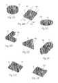
- FIG. 3is a perspective view of an alternative embodiment of a bone fixation/fusion device having a bony in-growth and/or through-growth region of a trabecular configuration.
- FIG. 4is a schematic view of a bone fixation/fusion device of the type shown in FIG. 1 , being inserted in association with bone across a fracture line or between different bone segments.
- FIG. 5is a schematic view of a bone fixation/fusion device positioned in association with a fracture line or between different bone segments with a bony in-growth and/or through growth region extending across the fracture line or space between different bone segments.
- FIG. 6is a front plan view of an alternative embodiment of a bone fixation/fusion device having a bony in-growth and/or bony through-growth region, in which the device has a conical configuration.
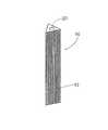
- FIG. 7is front plan view of an alternative embodiment of a bone fixation/fusion device having a bony in-growth and/or through-growth region in which the device has a beveled distal tip.
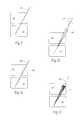
- FIGS. 8A and 8Bare schematics illustrating the insertion of a bone fixation/fusion device of the type shown in FIG. 6 in association with a fracture line or between different bone segments.
- FIG. 9is a schematic illustrating a guidewire being introduced into bone in association with a fracture line or between different bone segments.
- FIG. 10is a schematic similar to FIG. 9 and illustrating a drill bit being introduced over the guidewire.
- FIG. 11is a schematic similar to FIG. 10 and illustrating a bore formed in the bone remaining after withdrawal of the drill bit.
- FIG. 12is a schematic similar to FIG. 11 and illustrating insertion of a bone fixation/fusion device into the pre-formed bore.
- FIG. 13is an exploded front plan view illustrating the coupling of a pair of bone fixation/fusion by threaded engagement.
- FIG. 14is a schematic illustrating a pair of bone fixation/fusion devices coupled together and inserted in association with a fracture line or between different bone segments.
- FIG. 15is a front plan view illustrating passage of a bone fixation/fusion device through a fenestration in another bone fixation/fusion device.
- FIG. 16is a schematic illustrating the placement of a series of bone fixation/fusion devices in bone.
- FIG. 17is a top plan view of a bone fixation/fusion device positioned in association with a fracture line or between different bone segments.
- FIG. 18Ais a perspective view of an alternative embodiment of a bone fixation/fusion device having a bony in-growth and/or bony through-growth region that extends substantially along the entire device.
- FIG. 18Bis a perspective view of a bone fixation/fusion device similar to FIG. 18A and having a bony in-growth and/or bony through-growth region that extends along a portion of the device.
- FIG. 19is a top plan view of the bone fixation/fusion device of FIG. 18A in positioned in association with a fracture line or between different bone segments.
- FIG. 20is a top plan view of the bone fixation/fusion device of FIG. 18A positioned in association with a fracture line or between different bone segments and stabilized by fixation screws.
- FIGS. 21A to 21Fare perspective views illustrating alternative configurations of bone fixation/fusion devices of a type shown in FIG. 18A .
- FIGS. 22A and 22Bare perspective views illustrating alternative embodiments of the bone fixation/fusion of a type shown in FIG. 18A in which the device is profiled.
- FIGS. 23A and 23Bare perspective views illustrating alternative embodiments of the bone fixation/fusion device of a type shown in FIG. 1 with structural elements that provide an anti-rotational function.
- FIG. 24is a perspective view illustrating an alternative embodiment of the bone fixation/fusion device of a type shown FIG. 18A in which the device includes a series of grooves providing an anti-rotational function.
- FIG. 25is a perspective view illustrating an alternative embodiment of the bone fixation/fusion device of a type shown in FIG. 18A in which the device includes a pair of opposing wings providing an anti-rotational function.
- FIG. 26is a perspective view illustrating an alternative embodiment of the bone fixation/fusion device of FIG. 18A in which the device includes a pair of opposing flanges providing an anti-rotational function.
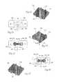
- FIG. 27is an exploded view of a pair of coupled bone fixation/fusion devices that, when fitted together, form a composite bone fixation/fusion device.
- FIG. 28is an assembled view of the composite bone fixation/fusion device formed from the assembly of the bone fixation/fusion devices shown in FIG. 27 .
- FIG. 29is a front view of the assembled composite bone fixation/fusion device of FIG. 28 positioned in association with a fracture line or between different bone segments.
- FIG. 30is a perspective view of an alternative embodiment of the bone fixation/fusion device of a type shown in FIG. 18A with fixation plates.
- FIG. 31is a perspective view of an alternative embodiment of the bone fixation/fusion device of FIG. 30 .
- FIG. 32is a side view of an alternative embodiment of a fixation plate having a rounded configuration.
- FIG. 33is a side view of an alternative embodiment of a fixation plate having a tapered configuration.
- FIG. 34is a perspective view of an alternative embodiment of the bone fixation/fusion device of a type shown in FIG. 18A providing a series of radially-extending fixation ridges.
- FIGS. 35A and 35Bare perspective views of a bone fixation/fusion device having a malleable region that can be flared or expanded to provide fixation and/or anti-rotation resistance.
- FIG. 36is a front plan view illustrating the drilling of pilot holes in adjacent bone segments, which can comprise a fracture line in the same bone or different bone segments.
- FIG. 37is a front plan view illustrating a cavity bored between the pilot holes to receive a bone fixation/fusion device.
- FIG. 38is a front plan view illustrating the placement of a pair of guide pins within the bored cavity.
- FIG. 39is a front plan view illustrating the placement of the bone fixation/fusion device into the cavity and removal of the guide pins.
- FIG. 40is a front plan view illustrating the placement of a pair of opposing c-shaped restraints within the bored cavity.
- FIG. 41is a front plan view illustrating the placement of the bone fixation/fusion device into the cavity within the restraints.
- FIG. 42is a front plan view illustrating a bone cavity like that shown in FIG. 37 to receive a bone fixation/fusion device, the bone cavity in FIG. 42 showing the inclusion of slots to receive fixation ridges formed on the bone fixation/fusion device, as shown in FIG. 43 .
- FIG. 43is a perspective view of a bone fixation/fusion device like that shown in FIG. 34 providing a series of radially-extending fixation ridges.
- FIG. 44is a front plan view showing placement of the bone fixation/fusion device shown in FIG. 43 in the slotted bone cavity shown in FIG. 42 , with the distance between the bone slots being generally equal to the distance between the fixation ridges.
- FIG. 45is a front plan view showing placement of the bone fixation/fusion device shown in FIG. 43 in the slotted bone cavity shown in FIG. 42 , with the distance between the bone slots being generally greater than the distance between the fixation ridges, to apply compression between adjacent bone segments.
- FIG. 46is a perspective view of a bone fixation/fusion device like that shown in FIG. 43 providing a series of radially-extending fixation ridges having curvilinear portions.
- FIG. 47is a top view showing placement of the bone fixation/fusion device shown in FIG. 46 , with curvilinear ridges, in a slotted bone cavity like that shown in FIG. 42 .
- FIG. 48is a perspective view of a bone fixation/fusion device like that shown in FIG. 46 providing a series of radially-extending fixation ridges having curvilinear portions.
- FIG. 49is a top view showing placement of the bone fixation/fusion device shown in FIG. 48 , with curvilinear ridges, in a slotted bone cavity like that shown in FIG. 42 .
- FIG. 50is a perspective view of a bone fixation/fusion device like that shown in FIG. 46 providing a series of radially-extending fixation ridges having curvilinear portions.
- FIG. 51is a side section view taken generally along line 51 - 51 in FIG. 50 , showing a ridge portion with a generally vertical draft.
- FIG. 52is a side section view taken generally along line 52 - 52 in FIG. 50 , showing a ridge portion with a more horizontal or angled draft, comprising a curvilinear ridge portion.
- FIG. 53is a top view showing placement of the bone fixation/fusion device shown in FIG. 50 , with curvilinear ridges, in a slotted bone cavity like that shown in FIG. 42 .
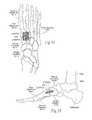
- FIG. 54is a superior anatomic view of a human foot, showing the placement of a bone fixation/fusion device of a type shown in FIG. 43 in a bone cavity in the first and second metatarsal bones, medial and middle cuneiform bones, and spanning the tarsometatarsal joint.
- FIG. 55is a medial side view of the human foot shown in FIG. 54 .
- FIG. 56is a perspective view of a bone fixation/fusion device like that shown in FIG. 43 showing the flexibility of the bone fixation/fusion device about an axis A.
- FIG. 57is a perspective view of a bone fixation/fusion device like that shown in FIG. 43 showing the flexibility of the bone fixation/fusion device about an axis B.
- FIG. 58is a perspective view of a bone fixation/fusion device like that shown in FIG. 43 providing a plurality of holes extending perpendicularly through the bone fixation/fusion device from the top to the bottom.
- FIG. 59is a perspective view of a bone fixation/fusion device like that shown in FIG. 43 providing a plurality of holes extending angularly through the bone fixation/fusion device from the top to the bottom.
- FIG. 60is a perspective view of a bone fixation/fusion device like that shown in FIG. 43 providing a plurality of holes extending perpendicularly through the bone fixation/fusion device from one side to the other.
- FIG. 61is a perspective view of a bone fixation/fusion device like that shown in FIG. 43 providing a plurality of holes extending angularly through the bone fixation/fusion device from one side to the other.
- FIG. 62is a perspective view of a bone fixation/fusion device like that shown in FIG. 43 providing a hollow cavity within the bone fixation/fusion device.
- FIG. 63is a front plan view illustrating a bone cavity like that shown in FIG. 42 to receive a bone fixation/fusion device, the bone cavity in FIG. 63 showing the inclusion of cylindrical end apertures to receive the cylindrical end caps formed on the bone fixation/fusion device, as shown in FIG. 64 .
- FIG. 64is a perspective view of a bone fixation/fusion device like that shown in FIG. 43 providing a pair of cylindrical end caps.
- FIG. 65is a front plan view showing placement of the bone fixation/fusion device shown in FIG. 64 in the cavity shown in FIG. 63 , with the distance between the center points of the cylindrical end apertures being generally equal to the distance between center points of the cylindrical end caps.
- FIG. 66is a front plan view showing placement of the bone fixation/fusion device shown in FIG. 64 in the cavity shown in FIG. 63 , with the distance between the center points of the cylindrical end apertures being generally greater than the distance between the center points of the cylindrical end caps, to appy compression between adjacent bone segments.
- FIG. 67is a perspective view of a bone fixation/fusion device like that shown in FIG. 43 providing a hollow cavity within the bone fixation/fusion device, and further including an accordion-like section to increase the flexibility of the device.
- FIGS. 1A and 1Bshow representative alternative configurations of a device 10 sized and configured for the fixation of bone fractures (i.e., fixation of parts of the same bone) or for the fixation of bones which are to be fused (arthrodesed) (i.e. fixation of two or more individual bones that are adjacent and/or jointed).
- the devicewill sometimes be called a bone fixation/fusion device, to indicate that it can perform a fixation function between two or more individual bones), or a fusion function between two or more parts of the same bone, or both functions.
- bone segmentsor “adjacent bone regions” refer to either situation, i.e., a fracture line in a single bone or a space between different bone segments.
- the bone fixation/fusion device 10comprises an elongated, stem-like structure.
- the device 10can be formed—e.g., by machining, molding, or extrusion—from a material usable in the prosthetic arts, including, but not limited to, titanium, titanium alloys, tantalum, chrome cobalt, surgical steel, or any other total joint replacement metal and/or ceramic, sintered glass, artificial bone, any uncemented metal or ceramic surface, or a combination thereof.
- the device 10may be formed from a suitable durable biologic material or a combination of metal and biologic material, such as a biocompatible bone-filling material.
- the device 10may be molded from a flowable biologic material, e.g., acrylic bone cement, that is cured, e.g., by UV light, to a non-flowable or solid material.
- the bone fixation/fusion device 10can take various shapes and have various cross-sectional geometries.
- the device 10can have, e.g., a generally curvilinear (i.e., round or oval) cross-section—as FIG. 1A shows—or a generally rectilinear cross section (i.e., square or rectangular or triangular—as FIG. 1B shows for purposes of illustration), or combinations thereof.
- a generally curvilinear (i.e., round or oval) cross-sectioni.e., round or oval
- a generally rectilinear cross sectioni.e., square or rectangular or triangular
- the body of the bone fixation/fusion device 10can be less elongated and form more of a flattened, “wafer” configuration, having, e.g., a rectangular, square, or disc shape.
- the bone fixation/fusion device 10desirably includes a region 12 formed along at least a portion of its length to promote bony in-growth onto or into surface of the device 10 and/or bony growth entirely through all or a portion of the device 10 .
- the region 12can comprise, e.g., through holes, and/or various surface patterns, and/or various surface textures, and/or pores, or combinations thereof.
- the device 10can be coated or wrapped or surfaced treated to provide the bony in-growth or through-growth region 12 , or it can be formed from a material that itself inherently possesses a structure conducive to bony in-growth or through-growth, such as a porous mesh, hydroxyapatite, or other porous surface.
- the device 10may further be covered with various other coatings such as antimicrobial, antithrombotic, and osteoinductive agents, or a combination thereof.
- the region 12may be impregnated with such agents, if desired.
- FIG. 1shows the region 12 as an open mesh configuration
- FIG. 2shows the region 12 as beaded configuration
- FIG. 3shows the region as a trabecular configuration. Any configuration conducive to bony in-growth and/or bony through-growth will suffice.
- the bone fixation/fusion device 10is inserted into a space between two adjacent bone surfaces, e.g., into a fracture site in a single bone or between two bones (e.g., adjacent vertebral bodies) which are to be fused together.
- the device 10is shown being tapped into bone through bone segments 14 (i.e., across a fracture line or between adjacent bones to be fused) with a tap 16 .
- the bonemay be drilled first to facilitate insertion of the device 10 .
- the bony in-growth or through-growth region 12 along the surface of the device 10accelerates bony in-growth or through-growth onto, into, or through the device 10 . Bony in-growth or through-growth onto, into, or through the device 10 helps speed up the fusion process or fracture healing time.
- the bony in-growth or through-growth region 12may extend along the entire outer surface of the device 10 , as shown in FIG. 4 , or the bony in-growth or through-growth region 12 may cover just a specified distance on either side of the bone segments or fracture line, as shown in FIG. 5 .
- the size and configuration of the device 10can be varied to accommodate the type and location of the bone to be treated as well as individual anatomy.
- the device 10can be angled or tapered in a conical configuration.
- the degree of anglecan be varied to accommodate specific needs or individual anatomy.
- a lesser degree of anglei.e., a more acute angle
- the device 10may also include a beveled distal tip 18 to further add in insertion of the device 10 into bone, as shown in FIG. 7 .
- the conical shapealso helps drive the bone segments or fracture fragments together, reducing the gap (G) between the bone segments 14 or fracture segments.
- the device 10is cannulated, having a central lumen or throughbore 20 extending through it, to assist in the placement of the device 10 within bone.
- FIG. 1Balso shows a cannulated throughbore 20 in a different configuration.
- the physiciancan insert a conventional guide pin 22 through the bone segments 14 by conventional methods, as FIG. 9 shows.
- a cannulated drill bit 24can then be introduced over the guide pin 22 , as seen in FIG. 10 .
- a single drill bit or multiple drill bits 24can be employed to drill through bone fragments or bone surfaces to create a bore 26 of the desired size and configuration.
- the drill bit 24is sized and configured to create a conical bore 26 similar in size and configuration to the device 10 .
- the bore 26is desirably sized and configured to permit tight engagement of the device 10 within the bore 26 and thereby restrict movement of the device 10 within the bore 26 .
- the pre-formed bore 26may be slightly smaller than the device 10 , while still allowing the device 10 to be secured into position within the bore 26 by tapping. As seen in FIG. 11 , the drill bit 24 is then withdrawn. The device 10 is then inserted into the bore 26 over the guide pin 22 , as FIG. 12 shows. The guide pin 22 is then withdrawn.
- the bone fixation/fusion device 10itself can include screw-like threads along the body for screwing the device into place.
- the device 10be self-tapping.
- the device 10can be cannulated for use with a guide pin 22 , or it need not be cannulated.
- Multiple devices 10may be employed to provide additional stabilization. While the use of multiple devices 10 will now be described illustrating the use of multiple devices 10 of the same size and configuration, it is contemplated that the devices 10 may also be of different size and/or configuration, e.g., one device 10 is of a cylindrical configuration and a second device 10 is of a conical configuration.
- a series of devices 10may be coupled together be any suitable means, e.g., by a snap fit engagement, or a groove and tab key arrangement, or by a Morse taper fit, or combinations thereof.
- a series of devices 10are coupled by threaded engagement.
- a first device 10 Aincludes a recess 28 at one end providing a series of internal threads 30 .
- the first device 10is of a cylindrical configuration, but may be of any desired configuration.
- the internal threads 30couple with a series of complementary external threads 32 on a second device 10 B of a similar or of a different configuration to couple the first and second devices 10 A and 10 B together.
- the devices 10 A and 10 Bare desirably coupled together prior to being inserted into the pre-formed bore 26 .
- the series of internal and external threads 30 and 32provide an interlocking mechanism that permits a series of devices 10 to be stacked and connected to cover a larger area or multiple bone segments 14 (e.g., a bone having multiple fractures) and thereby provides additional stabilization, as seen in FIG. 14 .
- FIG. 15illustrates another embodiment in which a device 10 ′ includes an opening or fenestration 34 to allow another device 10 to pass through, thereby providing additional stabilization.
- the fenestration 34can be sized and configured to permit another device 10 to be passed through the device 10 ′ at virtually any angle.
- the fenestration 34can also be sized and configured to limit movement of the second device 10 relative to the second device 10 ′.
- the physiciantaps a first device 10 ′ having a fenestration 34 through the bone segments.
- a second device 10is then inserted (e.g., by tapping) through the fenestration 34 of the first device 10 ′ into place.
- device 10 ′may also be adapted for coupling with another device 10 A (e.g., by a series of external and internal threads), permitting the devices 10 ′ and 10 A to be additionally stacked and connected, as also shown in FIG. 16 .
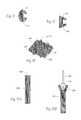
- FIG. 17illustrates an alternative form of a bone fixation/fusion device 100 .
- device 100includes a body 106 formed of a durable material that is not subject to significant bio-absorption or resorption by surrounding bone or tissue over time.
- the body 106is intended to remain in place for a time sufficient to stabilize the fracture or fusion site.
- Such materialsare well know in the prosthetic arts and include, e.g., titanium, titanium alloys, tantalum, chrome cobalt, surgical steel, or any other total joint replacement metal and/or ceramic, sintered glass, artificial bone, any uncemented metal or ceramic surface, or a combination thereof.
- the body 106 of the bone fixation/fusion device 100may be formed from a suitable durable biologic material or a combination of metal and biologic material, such as a biocompatible bone-filling material.
- the body 106 of the device 100may be molded from a flowable biologic material, e.g., acrylic bone cement, that is cured, e.g., by UV light, to a non-flowable or solid material.
- the body 106 of the device 100may also include a bony in-growth or through-growth region 108 , as already described in association with previous embodiments.
- the bone fixation/fusion device 100includes at least one region associated with the body 106 that, in contrast to the body 106 , comprises a material that is subject to more rapid in vivo bio-absorption or resorption by surrounding bone or tissue over time, e.g., within weeks or a few months.
- the resorbable materialcan comprise, e.g., polylactic acid (PLA), polyglycolic acid (PGA), poly(lactideglycolide) copolymers, polyanliydrides, cyclode, cirsns, polyorthoasters, n-vinyl alcohol, or other biosorbable polymers or like materials known or recognized in the prosthetic arts as having such characteristics.
- the bio-absorbable regionis intended to facilitate implantation or placement of the body 106 , but over time be absorbed to minimize the footprint of the implanted device 100 in the long run.
- the bioabsorbable region or regionscan possess functionality to aid in the implantation process.
- Region 102comprises a bioabsorbable screw region 102 , which is desirably threaded or otherwise suitably configured to pierce bone and facilitate advancement of the device 100 into bone.
- region 104comprises a bioabsorbable head region 104 , which is desirably configured to mate with an installation instrument, e.g., a screwdriver, to further facilitate advancement and positioning of the bone fixation/fusion device 100 in bone.
- the bioabsorbable head 104may also be sized and configured to temporarily anchor the device 100 within bone, e.g., the head 104 may be a slightly larger diameter than the body 106 of the device 100 .
- the bioabsorbable screw portion 102 and head portion 104are configured to provide an immediate benefit during the initial placement or position of the device 100 , but over time be resorbed when they have served their initial purpose during implantation. This leaves the more durable and less resorbable body 106 behind, to serve its longer-term function of stabilizing the fracture or fusion site.
- a given bone fixation/fusion devicecan take various shapes and geometries.
- the bone fixation/fusion device 200possesses a flattened rectangular (or wafer-like) configuration.
- a region 12 of the device 200can be textured or treated, as previously described, to provide bony in-growth or through-growth.
- the bony in-growth or through-growth region 12may extend along the entire device 200 (see FIG. 18A ) or along any portion or portions of the device 200 (see FIG. 18B ).
- the bone fixation/fusion device 200is desirably sized and configured to be positioned to join two or more adjacent bone segments 14 (which can comprise a fracture site, a fusion site, or both), as FIG. 19 shows, to fix and to promote the fusion of the adjacent bone segments 14 .
- the device 200may also be sized and configured to fix and to promote fusion of multiple bone segments 14 or compound fractures, as FIG. 20 shows.
- FIG. 20illustrates placement of the bone fixation/fusion device 200 sized and configured for the fixation and fusion of, for example, a first cuneiform (CE 1 ), a second cuneiform (CE 2 ), a first metatarsal (M 1 ), and a second metatarsal (M 2 ).
- auxiliary fixation elementssuch as conventional orthopedic screws 206 , may also be placed within and/or across the bone segments 14 by conventional techniques, to augment the stabilization of the bone segments 14 during the fusion process.
- the size and configuration of the bone fixation/fusion device 200may be modified or adjusted in diverse ways to serve the intended stabilization function in diverse bone locations, bone geometries, or bone types, which are intended to be fused or repaired.
- the bone fixation/fusion device 200can come in a family of different pre-established sizes and shapes, or it can be individually sized and configured to meet the requirements of a particular individual's anatomy.
- a given bone fixation/fusion device 200may take the form of a disc ( FIG. 21A ), a square ( FIG. 21B ), or an oval ( FIG. 21C ).
- the height, width, and length of a given bone fixation/fusion device 200may be varied depending on the specific location and amount of bone to be crossed for stabilization.
- a given bone fixation/fusion devicemay possess a symmetric geometry, or an asymmetric or complex geometry—such as an L shape ( FIG. 21D ), a triangle ( FIG. 21E ), or rectangle with a triangular ends ( FIG. 22F ). Any combination of linear or curvilinear or rounded geometries is possible.
- a given bone fixation/fusion devicecan be cannulated to aid in guidance during placement or implantation.
- the device 200can include a pair of opposing guide bores 202 .
- the guide bores 202are sized and configured to accommodate passage of guide pins 204 , which are secured at the intended site of device placement.
- Other forms of cannulated devices 200are shown in FIGS. 21B and 24 . In this way, the bone fixation/fusion device 200 can be guided by the pins 204 to the intended bone placement site.
- the devicemay be profiled.
- the bone fixation/fusion device 200may vary in height across its entire length of the device 200 , to form a tapered wedge.
- the bone fixation/fusion device 200may vary in height at one end only.
- the bone fixation/fusion device 200is desirably positioned with the area of greatest height in the proximal direction, which serves to wedge the device 200 into place within bone.
- the devicecan include one or more anti-rotational elements, which further stabilize and secure the device in the desired position within bone.
- the size and configuration of the anti-rotational elementsmay vary.
- the anti-rotational elementsmay comprise an array of fins 300 projecting from a stem-like device 10 ( FIG. 23A ), or an array of grooves 302 formed in a rectangular wafer device 200 ( FIG. 24 ), or wings 304 formed in a rectangular wafer device 200 ( FIG. 25 ), or flanges 306 projecting from a wafer device 200 ( FIG. 26 ).
- the anti-rotational elementscan comprise (see FIG.
- two or more bone fixation/fusion devices 200 of the types generally described abovemay be assembled to form a composite bone fixation/fusion device having a desired size and configuration.
- the bodies of two bone fixation/fusion devices 200each have a slot 208 .
- Slot 208 in a first device 200mates with a like or complementary slot 208 in a second device 200 to permit the assembly of a composite bone fixation/fusion device 310 , which has a crossed, anti-rotational configuration for placement across bone segments 14 .
- the crossed relation of the composite bone fixation/fusion device 310has an increased surface area and adds further stability to the devices 200 in bone during the fusion process.
- the location, size, and configuration of the slots 208may be varied to accommodate specific needs and a specific anatomical location as well as individual anatomy. It is also apparent that other mating configurations, e.g., groove and tab fitments, or snap-fit arrangements, or Morse taper fits, or threaded assemblies, can be use to assemble two or more bone fixation/fusion devices into a composite device 310 .
- fixation or gripping plates 212may be fitted to a given bone fixation/fusion device.
- the body of the bone fixation/fusion device 200includes one or more attachment sites 210 , e.g., slits or indentations, which are sized and configured to receive a selectively removable fixation or gripping plate 212 .
- attachment sites 210e.g., slits or indentations, which are sized and configured to receive a selectively removable fixation or gripping plate 212 .
- the plate 212When received within the slit 210 , the plate 212 extends radially from the device to grip into bone and further secure the device 200 within bone.
- the attachment site 210can include a tab 214 , which mates with a notch 216 in the fixation plate 212 to secure the plate 212 within the device 200 .
- tongue-and-groove fitments, or snap-fit arrangements, or threaded fitments, or Morse taper assembliescan be use to assemble one or more fixation or gripping plates to a bone fixation/fusion device.
- the fixation or gripping plate 212is formed of durable biocompatible metal or bone substitute material, as previously described. In some cases, it may be desirable to provide a bony in-growth surface on at least a portion of the plate 212 . Alternatively, the plate 212 may be formed of a bio-absorbable material, as already described.
- FIGS. 30 and 31illustrate embodiments in which the plates 212 present a generally blunt and flat configuration. It will be apparent to one of skill in the art that, however, that the plates 212 may also provide a sharpened or cutting edge or be otherwise sized and configured as necessary to accommodate specific location and individual anatomy. For example, the plate 212 may be rounded ( FIG. 32 ) or tapered ( FIG. 33 ).
- FIG. 34illustrates an alternative embodiment in which one or more fixation ridges 218 extend radially from the bone fixation/fusion device 200 . Similar to the fixation plates 212 , the ridges 218 may be variously sized and configured so as to grip into bone and further secure the bone fixation/fusion device 200 within bone.
- Fixation elementscan be formed in situ.
- a bone fixation/fusion device 200can include a malleable region 320 that normally presents a low-profile conducive to implantation.
- the profile of the malleable region 320can be changed in situ after implantation to a radially enlarged or extended profile 326 that provides stabilization or an anti-rotational function to the device 200 .
- the malleable region 320is slotted (see FIG. 35A ) to accommodate placement of a wedge tool 324 carried for manipulation by a stylet or cannula 322 (see FIG. 35B ).
- the wedge tool 324flays apart the slotted malleable region 320 (as FIG. 35B shows), to create the enlarged profile 326 for stabilization and/or rotation resistance.
- pilot holes 220are drilled into adjacent bone segments 14 (e.g., along a fracture line in a single bone or between adjacent segments of different bones) by conventional surgical techniques.
- a single pilot hole 220is drilled into each bone segment 14 . It is to be understood that the number and configuration of the pilot holes 220 may vary as necessary or as desired.
- the physiciancan then then saw, using conventional methods, between the pilot holes 220 to prepare a cavity 222 to receive the device 200 .
- Guide pins 204may, if desired, be placed at opposing ends of the bored cavity 222 , as seen in FIG. 38 . In this arrangement, as shown in FIG. 39 , the selected bone fixation/fusion device 200 is passed over the guide pins 204 to position the device 200 with the cavity 222 . The guide pins 204 may then be removed. In an alternative arrangement, guide pins 204 need not be used, and the device 200 is manually inserted by the physician into the bore cavity 222 .
- FIGS. 40 and 41An alternative embodiment is illustrated in FIGS. 40 and 41 .
- a c-shaped restraint 224is placed against each end of the bored cavity 222 .
- the selected bone fixation/fusion device 200is then positioned between the restraints 222 such that the restraints 222 engage the device 200 to secure the device 200 within bone.
- slots 230can be sawed or cut within the bored cavity 222 using conventional tools, as FIG. 42 shows.
- the slots 230are sized and configured so that the ridges 218 nest with the slots 230 , to fixate the ridges 218 and thus the fixation/fusion device 200 within and between the adjacent bone segments 14 .
- the nesting relationship between the ridges 218 and the slots 230put the adjacent bone segments into compression, at least resisting further enlargement of the distance between them.
- the slots 230are formed in a spaced-apart relationship within the respective bone segments 14 , at a distance designated D S in FIG. 42 .
- the distance D Stakes into account the distance between the fixation ridges of the device 200 , designated D F in FIG. 42 .
- D Fis at least generally equal to and is not substantially greater than D S .
- the distance between the adjacent bone segments 14designated G 1 in FIG. 42 (which can comprise a fracture line in a single bone or a gap between adjacent segments of different bone)
- G 1 in FIG. 42which can comprise a fracture line in a single bone or a gap between adjacent segments of different bone
- FIG. 44shows that D F is generally equal to D S .
- the interval G 1 between the adjacent bone segments 14 before installation of the device 200 ( FIG. 42 )is generally the same after installation of the device 200 ( FIG. 44 ).
- the distance D S between the slots 230slightly larger (e.g., from about at least 0.5 mm to about 3 mm farther apart) than the distance D F between the ridges 218 .
- This arrangementis shown in FIG. 45 .
- the ridges 218serve to pull the adjacent bone segments closer together, while also applying compression to maintain this condition (as shown by arrows in FIG. 45 ).
- FIGS. 42 and 45show, the interval G 2 between the adjacent bone segments 14 after installation of the device 200 ( FIG. 45 ) is smaller than the interval G 1 before installation of the device 200 ( FIG. 42 ).
- the ridges 218 shown in the preceding embodimentsare generally uniformly linear in configuration. As shown in FIG. 46 , the ridges 218 can be non-uniform and curvilinear in configuration, meaning that the ridges 218 can include portions that curve or are otherwise not uniformly straight.
- the curvilinear configurationcan vary.
- FIG. 46shows, as one representative embodiment, curvilinear ridges 218 , each of which includes generally linear end portions 232 and a curved, non-linear (curvilinear) intermediate portion 234 .
- the distance R 1 between the linear end portions 232is greater than the distance R 2 between the curved intermediate portion 234 .
- the curved portions 234generally face inward toward the centerline of the device 200 in a symmetric fashion. It should be appreciated, that an asymmetric arrangement between the linear and curved portions 232 and 234 among the ridges 218 can be used.
- the curvilinear ridges 218nest within the formed slots 230 , which can themselves be more easily formed in bone in a linear fashion.
- the undulating curved portions 234 of the curvilinear ridges 218abut against or otherwise extend closer to the walls the formed linear slots 234 than the linear portions 232 .
- the presence of curvilinear ridges 218reduces or prevents “play” or lateral shifting of the device 200 within the bone cavity 222 after being placed in adjacent bone segments 14 .
- the curvilinear ridges 218stabilize or fixate placement of the device 200 within the bone cavity 222 , accommodating differences in dimensional tolerances that may exist between the ridges 218 on the device 200 and slots 230 formed in the bone cavity 222 .
- the curvilinear ridges 218also serve to augment compression (shown by arrows in FIG. 47 ) between the adjacent bone segments 14 , to establish and maintain a desired relationship between them for fusion or fixation purposes.
- FIG. 48shows, as another representative embodiment, curvilinear ridges 218 , each of which includes a generally linear first end portion 236 and a non-linear, curved (curvilinear) second end portion 238 .
- the distance R 1 between the linear first end portions 236is greater than the distance R 2 between the curved second end portion 238 .
- the curved end portions 236extend generally inward toward the centerline of the device 200 in a symmetric fashion. Again, it should be appreciated that an asymmetric arrangement of linear and curvilinear portions among the ridges 218 can be used.
- FIG. 49shows, when the curvilinear ridges 218 nest within the formed linear slots 230 , the undulating curved end portions 238 abut against or otherwise extend closer to the walls the formed linear slots 230 than the linear end portions 236 .
- the presence of curvilinear ridges 218 in the arrangement shown in FIG. 49reduces or prevents “play” or lateral shifting of the device 200 within the formed linear slots 230 .
- the curvilinear ridges 218also apply and maintain compression between the adjacent bone segments 14 to establish and maintain a desired relationship between them (as shown by arrows in FIG. 49 ).
- FIG. 50shows another representative embodiment of curvilinear ridges 218 .
- the draft of the ridges 218changes between a vertical draft 240 on the end portions of the ridges 218 (see FIG. 51 ) to a more horizontal or angular draft 242 on the intermediate portion of the ridges 218 (see FIG. 52 ).
- the more horizontal or angular drafts 242face inward toward the centerline of the device 200 , however, the drafts 242 could face in an opposite direction away from the centerline, and in an asymmetric way.
- the distance R 1 between the vertical drafts 240 of the ridges 218is greater than the distance R 2 between the more horizontal drafts 242 of the ridges.
- FIG. 53shows, when the curvilinear ridges 218 nest within the formed linear slots 230 , the more horizontal drafts 242 abut or otherwise rest closer to the walls the formed linear slots 230 than the vertical drafts 240 .
- the presence of different curvilinear ridge drafts 240 and 242 in the arrangement shown in FIG. 53reduces or prevents lateral “play” or shifting of the device 200 within the formed linear slots 230 due, e.g., to differences in dimensional tolerances among the ridges 218 on the device 200 and slots 230 formed in the bone cavity 222 .
- the curvilinear ridges 218 formed by the different drafts 240 and 242also apply and maintain compression between the adjacent bone segments to establish and maintain a desired relationship between them (as shown by arrows in FIG. 53 ).
- FIGS. 54 and 55show anatomic views of a representative placement of the bone fixation/fusion device 200 as previously described.
- the device 200is placed between adjacent bone segments comprising the first and second metatarsal bones and the medial and middle cuneiform bones. In this arrangement, the device 200 also spans portion of the tarsometatarsal joint. The presence of the device 200 serves to fixate these adjacent bone segments and fuse the joint.
- the device 200includes fixation ridges 218 as previously described; however, devices 200 without ridges 218 , or with curvilinear ridges, can be used for this purpose as well.
- the device 200be flexible. It may be desired that the device 200 is flexible about an axis A which extends across the width of the device and is generally parallel to the fracture line or gap between bones to be fused (see FIG. 56 ). It may also be desired that the device 200 is flexible about an axis B which extends across the length of the device and is generally perpendicular to the fracture line or gap (see FIG. 57 ). It may also be desirable that the device 200 be flexible about both axes. Various configurations may be used to achieve flexibility.
- the device 200may be formed with a plurality of holes 240 extending through the device.
- Various hole 240 configurationsmay be used to achieve the desired flexibility.
- the holes 240can extend through the device 200 from the top to the bottom, perpendicular to the top surface as shown in FIG. 58 .
- the holes 240can extend from the top of the device 200 to the bottom of the device at an angle as shown in FIG. 59 .
- the holes 240can extend from one side of the device 200 to the opposite side, perpendicular to the surface of the side as shown in FIG. 60 .
- the holes 240can extend through the device 200 at an angle as shown in FIG. 61 .
- the device 200can be formed with a hollow cavity 242 to increase the flexibility of the device 200 .
- the device 400can be formed with an accordion-like section 452 to increase the flexibility of the device 400 .
- the bone fixation/fusion device 300can have a rod-like configuration.
- the device 300includes a central rectangular portion 342 formed with two cylindrical end caps 344 .
- Each cylindrical end cap 344has a center point 346 (see FIG. 64 ).
- the distance between end cap center points 346is designated as D F .
- the device 300fits in a slot 222 cut in two bone segments 14 in generally the same manner as is described above.
- the slot 222is cut with a cylindrical end aperture 348 at each end of the slot 222 .
- Each cylindrical end aperture 348has a center point 350 (see FIG. 63 ).
- the distance between these aperture center points 350is designated as D S .
- D Sat least generally equal to and is not substantially greater than D F .
- the distance between the adjacent bone fragmentsis not enlarged by the presence of the device 300 .
- D Sis approximately equal to D F .
- the interval G 1 between the adjacent bone segments 14 before installation of the device 300is the same as after installation of the device 300 .
- the distance D S between the aperture center points 350slightly larger than the distance D F between the end cap center points 346 .
- This arrangementis shown in FIG. 66 .
- the cylindrical end caps 344serve to pull the adjacent bone segments 14 together, while also applying compression to maintain this condition (as shown by arrows in FIG. 66 ).
- FIGS. 63 and 66show, the interval G 1 between the bone segments before installation of the device 300 is greater than the interval G 2 after installation of the device 300 .
Landscapes
- Health & Medical Sciences (AREA)
- Orthopedic Medicine & Surgery (AREA)
- Life Sciences & Earth Sciences (AREA)
- Surgery (AREA)
- Engineering & Computer Science (AREA)
- Biomedical Technology (AREA)
- Animal Behavior & Ethology (AREA)
- Veterinary Medicine (AREA)
- Public Health (AREA)
- Heart & Thoracic Surgery (AREA)
- General Health & Medical Sciences (AREA)
- Molecular Biology (AREA)
- Medical Informatics (AREA)
- Nuclear Medicine, Radiotherapy & Molecular Imaging (AREA)
- Neurology (AREA)
- Oral & Maxillofacial Surgery (AREA)
- Dentistry (AREA)
- Cardiology (AREA)
- Transplantation (AREA)
- Vascular Medicine (AREA)
- Surgical Instruments (AREA)
- Prostheses (AREA)
Abstract
Description
Claims (2)
Priority Applications (2)
| Application Number | Priority Date | Filing Date | Title |
|---|---|---|---|
| US12/930,791US9622783B2 (en) | 2004-08-09 | 2011-01-18 | Systems and methods for the fixation or fusion of bone |
| US15/461,304US9956013B2 (en) | 2004-08-09 | 2017-03-16 | Systems and methods for the fixation or fusion of bone |
Applications Claiming Priority (4)
| Application Number | Priority Date | Filing Date | Title |
|---|---|---|---|
| US10/914,629US20060036251A1 (en) | 2004-08-09 | 2004-08-09 | Systems and methods for the fixation or fusion of bone |
| US11/136,141US7922765B2 (en) | 2004-08-09 | 2005-05-24 | Systems and methods for the fixation or fusion of bone |
| US11/653,504US20070156241A1 (en) | 2004-08-09 | 2007-01-16 | Systems and methods for the fixation or fusion of bone |
| US12/930,791US9622783B2 (en) | 2004-08-09 | 2011-01-18 | Systems and methods for the fixation or fusion of bone |
Related Parent Applications (1)
| Application Number | Title | Priority Date | Filing Date |
|---|---|---|---|
| US11/653,504DivisionUS20070156241A1 (en) | 2004-08-09 | 2007-01-16 | Systems and methods for the fixation or fusion of bone |
Related Child Applications (1)
| Application Number | Title | Priority Date | Filing Date |
|---|---|---|---|
| US15/461,304DivisionUS9956013B2 (en) | 2004-08-09 | 2017-03-16 | Systems and methods for the fixation or fusion of bone |
Publications (2)
| Publication Number | Publication Date |
|---|---|
| US20110118796A1 US20110118796A1 (en) | 2011-05-19 |
| US9622783B2true US9622783B2 (en) | 2017-04-18 |
Family
ID=39638829
Family Applications (3)
| Application Number | Title | Priority Date | Filing Date |
|---|---|---|---|
| US11/653,504AbandonedUS20070156241A1 (en) | 2004-08-09 | 2007-01-16 | Systems and methods for the fixation or fusion of bone |
| US12/930,791Expired - Fee RelatedUS9622783B2 (en) | 2004-08-09 | 2011-01-18 | Systems and methods for the fixation or fusion of bone |
| US15/461,304Expired - LifetimeUS9956013B2 (en) | 2004-08-09 | 2017-03-16 | Systems and methods for the fixation or fusion of bone |
Family Applications Before (1)
| Application Number | Title | Priority Date | Filing Date |
|---|---|---|---|
| US11/653,504AbandonedUS20070156241A1 (en) | 2004-08-09 | 2007-01-16 | Systems and methods for the fixation or fusion of bone |
Family Applications After (1)
| Application Number | Title | Priority Date | Filing Date |
|---|---|---|---|
| US15/461,304Expired - LifetimeUS9956013B2 (en) | 2004-08-09 | 2017-03-16 | Systems and methods for the fixation or fusion of bone |
Country Status (2)
| Country | Link |
|---|---|
| US (3) | US20070156241A1 (en) |
| WO (1) | WO2008088685A2 (en) |
Cited By (23)
| Publication number | Priority date | Publication date | Assignee | Title |
|---|---|---|---|---|
| US20170181770A1 (en)* | 2004-08-09 | 2017-06-29 | Mark A. Reiley | Systems and methods for the fixation or fusion of bone |
| US20180055521A1 (en)* | 2010-01-13 | 2018-03-01 | Jcbd, Llc | Methods of fusing a sacroiliac joint |
| US10004547B2 (en) | 2004-08-09 | 2018-06-26 | Si-Bone Inc. | Systems and methods for the fixation or fusion of bone at or near a sacroiliac joint |
| US10058430B2 (en)* | 2010-01-13 | 2018-08-28 | Jcbd, Llc | Methods of fusing a sacroiliac joint with an additively manufactured sacroiliac joint implant |
| US10194962B2 (en) | 2014-09-18 | 2019-02-05 | Si-Bone Inc. | Matrix implant |
| US20200345507A1 (en)* | 2005-05-24 | 2020-11-05 | Si-Bone Inc. | Apparatus, systems, and methods for the fixation or fusion of bone |
| US10959758B2 (en) | 2013-03-15 | 2021-03-30 | Si-Bone Inc. | Implants for spinal fixation or fusion |
| US11116519B2 (en) | 2017-09-26 | 2021-09-14 | Si-Bone Inc. | Systems and methods for decorticating the sacroiliac joint |
| US11147688B2 (en) | 2013-10-15 | 2021-10-19 | Si-Bone Inc. | Implant placement |
| US11234830B2 (en) | 2019-02-14 | 2022-02-01 | Si-Bone Inc. | Implants for spinal fixation and or fusion |
| US11266450B2 (en)* | 2017-04-11 | 2022-03-08 | Waldemar Link Gmbh & Co. Kg | Arthrodesis plate |
| US11291485B2 (en) | 2012-05-04 | 2022-04-05 | Si-Bone Inc. | Fenestrated implant |
| US11337821B2 (en) | 2012-03-09 | 2022-05-24 | Si-Bone Inc. | Integrated implant |
| US11369419B2 (en) | 2019-02-14 | 2022-06-28 | Si-Bone Inc. | Implants for spinal fixation and or fusion |
| US11471286B2 (en) | 2012-03-09 | 2022-10-18 | Si-Bone Inc. | Systems, devices, and methods for joint fusion |
| US11571245B2 (en) | 2019-11-27 | 2023-02-07 | Si-Bone Inc. | Bone stabilizing implants and methods of placement across SI joints |
| US11684378B2 (en) | 2014-09-18 | 2023-06-27 | Si-Bone Inc. | Implants for bone fixation or fusion |
| US11752011B2 (en) | 2020-12-09 | 2023-09-12 | Si-Bone Inc. | Sacro-iliac joint stabilizing implants and methods of implantation |
| US12083026B2 (en) | 2019-12-09 | 2024-09-10 | Si-Bone Inc. | Sacro-iliac joint stabilizing implants and methods of implantation |
| US12097127B2 (en) | 2020-10-30 | 2024-09-24 | Waldemar Link Gmbh &Co. Kg | Implantation tool for an interphalangeal implant |
| US12419668B2 (en) | 2019-11-21 | 2025-09-23 | Si-Bone Inc. | Rod coupling assemblies for bone stabilization constructs |
| US12427028B2 (en) | 2018-03-28 | 2025-09-30 | Si-Bone Inc. | Threaded implants and methods of use across bone segments |
| US12433733B2 (en) | 2023-08-15 | 2025-10-07 | Si-Bone Inc. | Pelvic stabilization implants, methods of use and manufacture |
Families Citing this family (79)
| Publication number | Priority date | Publication date | Assignee | Title |
|---|---|---|---|---|
| WO2004014243A1 (en) | 2002-08-10 | 2004-02-19 | William H Simon | Method and apparatus for repairing the mid-food region via an intermedullary nail |
| US7648509B2 (en) | 2003-03-10 | 2010-01-19 | Ilion Medical Llc | Sacroiliac joint immobilization |
| US20060036251A1 (en) | 2004-08-09 | 2006-02-16 | Reiley Mark A | Systems and methods for the fixation or fusion of bone |
| US8388667B2 (en) | 2004-08-09 | 2013-03-05 | Si-Bone, Inc. | Systems and methods for the fixation or fusion of bone using compressive implants |
| US8414648B2 (en)* | 2004-08-09 | 2013-04-09 | Si-Bone Inc. | Apparatus, systems, and methods for achieving trans-iliac lumbar fusion |
| US8425570B2 (en) | 2004-08-09 | 2013-04-23 | Si-Bone Inc. | Apparatus, systems, and methods for achieving anterior lumbar interbody fusion |
| US8470004B2 (en) | 2004-08-09 | 2013-06-25 | Si-Bone Inc. | Apparatus, systems, and methods for stabilizing a spondylolisthesis |
| US8444693B2 (en)* | 2004-08-09 | 2013-05-21 | Si-Bone Inc. | Apparatus, systems, and methods for achieving lumbar facet fusion |
| US9949843B2 (en) | 2004-08-09 | 2018-04-24 | Si-Bone Inc. | Apparatus, systems, and methods for the fixation or fusion of bone |
| FR2884406B1 (en) | 2005-04-14 | 2008-10-17 | Memometal Technologies Soc Par | INTRAMEDULAR OSTEOSYNTHESIS DEVICE OF TWO BONE PARTS, IN PARTICULAR HAND AND / OR FOOT |
| US7901431B2 (en)* | 2007-01-17 | 2011-03-08 | Arthrex, Inc. | Lisfranc repair using suture-button construct |
| FR2913876B1 (en) | 2007-03-20 | 2009-06-05 | Memometal Technologies Soc Par | OSTEOSYNTHESIS DEVICE |
| EP2117479B1 (en)* | 2007-08-31 | 2014-11-12 | Ilion Medical LLC | Sacroiliac joint immobilzation |
| US8740912B2 (en) | 2008-02-27 | 2014-06-03 | Ilion Medical Llc | Tools for performing less invasive orthopedic joint procedures |
| FR2935601B1 (en) | 2008-09-09 | 2010-10-01 | Memometal Technologies | INTRAMEDULLARY IMPLANT RESORBABLE BETWEEN TWO BONE OR TWO BONE FRAGMENTS |
| EP2367484A4 (en)* | 2008-12-04 | 2012-09-12 | Si Bone Inc | Systems and methods for the fixation or fusion of bone at or near a sacroiliac joint |
| US8864773B2 (en)* | 2009-01-14 | 2014-10-21 | Globus Medical, Inc. | Devices and methods for treating vertebral fractures |
| US9039414B2 (en)* | 2009-02-06 | 2015-05-26 | Scott E. Bulloch | Drill guide pin, shank, cannulated drill bit, and driver for creating a hole in a bone |
| US20100203479A1 (en)* | 2009-02-06 | 2010-08-12 | Bulloch Scott E | Dental implant system and methods |
| US8348950B2 (en) | 2010-01-04 | 2013-01-08 | Zyga Technology, Inc. | Sacroiliac fusion system |
| WO2014015309A1 (en) | 2012-07-20 | 2014-01-23 | Jcbd, Llc | Orthopedic anchoring system and methods |
| US9381045B2 (en) | 2010-01-13 | 2016-07-05 | Jcbd, Llc | Sacroiliac joint implant and sacroiliac joint instrument for fusing a sacroiliac joint |
| US9421109B2 (en) | 2010-01-13 | 2016-08-23 | Jcbd, Llc | Systems and methods of fusing a sacroiliac joint |
| US8900251B2 (en) | 2010-05-28 | 2014-12-02 | Zyga Technology, Inc | Radial deployment surgical tool |
| US9402736B2 (en)* | 2010-07-12 | 2016-08-02 | Alphatec Spine, Inc. | Interbody fusion implant and related methods |
| US12409039B2 (en)* | 2010-07-27 | 2025-09-09 | Tenon Medical, Inc. | Systems for sacroiliac joint stabilization |
| CA2806755C (en)* | 2010-07-27 | 2018-07-10 | Richard S. Ginn | System for sacro-iliac stabilization |
| US9220535B2 (en)* | 2010-10-26 | 2015-12-29 | Christian Röbling | Process for introducing a stabilizing element into a vertebral column |
| CA2833543A1 (en) | 2011-05-05 | 2012-11-08 | Zyga Technology, Inc. | Sacroiliac fusion system |
| US8900279B2 (en) | 2011-06-09 | 2014-12-02 | Zyga Technology, Inc. | Bone screw |
| EP2720628B1 (en) | 2011-06-17 | 2021-08-11 | Jcbd, Llc | Sacroiliac joint implant system |
| US9283006B2 (en)* | 2011-09-22 | 2016-03-15 | Mx Orthopedics, Corp. | Osteosynthetic shape memory material intramedullary bone stent and method for treating a bone fracture using the same |
| US9615856B2 (en)* | 2011-11-01 | 2017-04-11 | Imds Llc | Sacroiliac fusion cage |
| US8778026B2 (en) | 2012-03-09 | 2014-07-15 | Si-Bone Inc. | Artificial SI joint |
| US10179014B1 (en) | 2012-06-01 | 2019-01-15 | Nuvasive, Inc. | Systems and methods for promoting sacroiliac joint fusion |
| DE202012103384U1 (en) | 2012-09-05 | 2012-09-24 | Signus Medizintechnik Gmbh | Pelvic ring implant |
| US9737294B2 (en) | 2013-01-28 | 2017-08-22 | Cartiva, Inc. | Method and system for orthopedic repair |
| US10179012B2 (en) | 2013-01-28 | 2019-01-15 | Cartiva, Inc. | Systems and methods for orthopedic repair |
| US9826986B2 (en) | 2013-07-30 | 2017-11-28 | Jcbd, Llc | Systems for and methods of preparing a sacroiliac joint for fusion |
| US10245087B2 (en) | 2013-03-15 | 2019-04-02 | Jcbd, Llc | Systems and methods for fusing a sacroiliac joint and anchoring an orthopedic appliance |
| US9510872B2 (en) | 2013-03-15 | 2016-12-06 | Jcbd, Llc | Spinal stabilization system |
| US9700356B2 (en) | 2013-07-30 | 2017-07-11 | Jcbd, Llc | Systems for and methods of fusing a sacroiliac joint |
| US9717539B2 (en) | 2013-07-30 | 2017-08-01 | Jcbd, Llc | Implants, systems, and methods for fusing a sacroiliac joint |
| US9839448B2 (en)* | 2013-10-15 | 2017-12-12 | Si-Bone Inc. | Implant placement |
| AU2014365821B2 (en) | 2013-12-20 | 2019-10-03 | Crossroads Extremity Systems, Llc | Polyaxial locking hole |
| US9861375B2 (en) | 2014-01-09 | 2018-01-09 | Zyga Technology, Inc. | Undercutting system for use in conjunction with sacroiliac fusion |
| US9801546B2 (en) | 2014-05-27 | 2017-10-31 | Jcbd, Llc | Systems for and methods of diagnosing and treating a sacroiliac joint disorder |
| US10045803B2 (en) | 2014-07-03 | 2018-08-14 | Mayo Foundation For Medical Education And Research | Sacroiliac joint fusion screw and method |
| JP2017529886A (en) | 2014-07-10 | 2017-10-12 | クロスローズ エクストリミティ システムズ リミテッド ライアビリティ カンパニー | Bone implant and means of insertion |
| US11202626B2 (en) | 2014-07-10 | 2021-12-21 | Crossroads Extremity Systems, Llc | Bone implant with means for multi directional force and means of insertion |
| WO2016044053A1 (en) | 2014-09-19 | 2016-03-24 | Crossroads Extremity Systems, Llc | Bone fixation implant and means of fixation |
| US9452056B2 (en) | 2014-09-29 | 2016-09-27 | Biomet C.V. | Implants for fixation of the distal tibia |
| US10166022B2 (en)* | 2014-09-29 | 2019-01-01 | Biomet C.V. | Method and apparatus for bone fixation |
| US10383733B2 (en) | 2014-10-22 | 2019-08-20 | Biomet C.V. | Method and apparatus for bone fixation |
| US9757168B2 (en) | 2015-03-03 | 2017-09-12 | Howmedica Osteonics Corp. | Orthopedic implant and methods of implanting and removing same |
| US9763800B2 (en)* | 2015-03-18 | 2017-09-19 | Biomet C. V. | Implant configured for hammertoe and small bone fixation |
| US10376206B2 (en) | 2015-04-01 | 2019-08-13 | Si-Bone Inc. | Neuromonitoring systems and methods for bone fixation or fusion procedures |
| US10413332B2 (en) | 2016-04-25 | 2019-09-17 | Imds Llc | Joint fusion implant and methods |
| US9833321B2 (en) | 2016-04-25 | 2017-12-05 | Imds Llc | Joint fusion instrumentation and methods |
| EP3251621B1 (en) | 2016-06-03 | 2021-01-20 | Stryker European Holdings I, LLC | Intramedullary implant |
| US11864753B2 (en) | 2017-02-06 | 2024-01-09 | Crossroads Extremity Systems, Llc | Implant inserter |
| EP3579762B1 (en) | 2017-02-07 | 2024-06-26 | Crossroads Extremity Systems, LLC | Counter-torque implant |
| AU2018225123C1 (en) | 2017-02-21 | 2020-03-19 | Biomet Manufacturing, Llc | Implants for bridging osseous defects |
| EP3592265B1 (en) | 2017-03-10 | 2023-09-20 | Paragon 28, Inc. | Bone implant devices |
| USD870284S1 (en) | 2017-07-31 | 2019-12-17 | Crossroads Extremity Systems, Llc | Osteosynthesis clip |
| US10603055B2 (en) | 2017-09-15 | 2020-03-31 | Jcbd, Llc | Systems for and methods of preparing and fusing a sacroiliac joint |
| US10729555B1 (en)* | 2017-10-30 | 2020-08-04 | Presidio Surgical, Inc. | Implantable spinal support structure and method |
| US12295628B2 (en) | 2018-11-01 | 2025-05-13 | Howmedica Osteonics Corp. | Device for fixating orthopedic injury |
| US11154402B1 (en) | 2019-10-04 | 2021-10-26 | Pain TEQ, LLC | Instrumentation for fusing a sacroiliac joint |
| EP4037618A4 (en) | 2019-10-04 | 2023-12-13 | PTL Opco LLC | Allograft implant for fusing a sacroiliac joint |
| US11058550B2 (en) | 2019-10-04 | 2021-07-13 | Pain TEQ, LLC | Allograft implant for fusing a sacroiliac joint |
| WO2021097491A1 (en) | 2019-11-15 | 2021-05-20 | Paragon 28, Inc. | Instruments, systems, and methods of using |
| US12059183B2 (en) | 2020-07-31 | 2024-08-13 | Crossroads Extremity Systems, Llc | Bone plates with dynamic elements and screws |
| USD961081S1 (en) | 2020-11-18 | 2022-08-16 | Crossroads Extremity Systems, Llc | Orthopedic implant |
| WO2023064785A1 (en) | 2021-10-12 | 2023-04-20 | Lee Randall F | System and method for a medical implant with integrated propulsors |
| AU2023242748A1 (en)* | 2022-04-01 | 2024-10-17 | Djit Medtech, Inc. | Stemless semi-constrained implantable joint replacement device |
| US11931053B2 (en) | 2022-08-04 | 2024-03-19 | PTL Opco, LLC | Single-use joint decorticator apparatus |
| US12290445B1 (en) | 2024-05-03 | 2025-05-06 | Djit Medtech, Inc. | Joint implants with bone interface connectors |
| US12427023B1 (en) | 2024-09-05 | 2025-09-30 | Djit Medtech, Inc. | Joint implants with interface surfaces having registration features |
Citations (319)
| Publication number | Priority date | Publication date | Assignee | Title |
|---|---|---|---|---|
| US1951278A (en)* | 1932-02-13 | 1934-03-13 | Ericsson Ernst Axel Johan | Fracture nail |
| US2136471A (en)* | 1937-06-30 | 1938-11-15 | Rudolph H Schneider | Bone pin |
| US2243717A (en)* | 1938-09-20 | 1941-05-27 | Moreira Franciseo Elias Godoy | Surgical device |
| US2414882A (en)* | 1943-09-24 | 1947-01-28 | Herschel Leiter H | Fracture reduction apparatus |
| US2562419A (en) | 1948-04-05 | 1951-07-31 | George L Ferris | Expansion nut setting tool |
| US2675801A (en)* | 1954-04-20 | Intramedbllary nail | ||
| US2697433A (en) | 1951-12-04 | 1954-12-21 | Max A Zehnder | Device for accurately positioning and guiding guide wires used in the nailing of thefemoral neck |
| US3076453A (en) | 1961-01-16 | 1963-02-05 | Raymond G Tronzo | Hip nail |
| US3506982A (en) | 1965-06-21 | 1970-04-21 | Cleveland Clinic | Endoprosthetic joints |
| US3694821A (en) | 1970-11-02 | 1972-10-03 | Walter D Moritz | Artificial skeletal joint |
| US3709218A (en) | 1970-04-24 | 1973-01-09 | W Halloran | Combination intramedullary fixation and external bone compression apparatus |
| US3744488A (en) | 1971-06-08 | 1973-07-10 | J Cox | Bone splint |
| US4059115A (en) | 1976-06-14 | 1977-11-22 | Georgy Stepanovich Jumashev | Surgical instrument for operation of anterior fenestrated spondylodessis in vertebral osteochondrosis |
| US4156943A (en) | 1977-08-24 | 1979-06-05 | Collier John P | High-strength porous prosthetic device and process for making the same |
| US4292964A (en) | 1979-01-19 | 1981-10-06 | Ulrich Max B | Method of and apparatus for pinning a fractured pelvis |
| US4341206A (en)* | 1978-12-19 | 1982-07-27 | Synthes Ag | Device for producing a hole in a bone |
| US4344190A (en) | 1979-07-25 | 1982-08-17 | University Of Exeter | Plugs for the medullary canal of a bone |
| US4399813A (en) | 1981-01-22 | 1983-08-23 | Barber Forest C | Apparatus and method for removing a prosthesis embedded in skeletal bone |
| US4423721A (en) | 1978-09-04 | 1984-01-03 | Schwarzkopf Development Corporation | Device for insertion and extraction of medullary nails |
| US4475545A (en)* | 1982-12-06 | 1984-10-09 | Ender Hans G | Bone-nail |
| US4501269A (en) | 1981-12-11 | 1985-02-26 | Washington State University Research Foundation, Inc. | Process for fusing bone joints |
| US4569338A (en) | 1984-02-09 | 1986-02-11 | Edwards Charles C | Sacral fixation device |
| US4612918A (en) | 1984-10-16 | 1986-09-23 | Barclay Slocum | Method of eliminating canine cauda equina syndrome |
| US4622959A (en)* | 1985-03-05 | 1986-11-18 | Marcus Randall E | Multi-use femoral intramedullary nail |
| US4630601A (en) | 1982-05-18 | 1986-12-23 | Howmedica International, Inc. | Bone nail for the treatment of fractures |
| US4638799A (en) | 1985-06-13 | 1987-01-27 | Moore Robert R | Needle guide apparatus for discolysis procedures |
| US4657550A (en) | 1984-12-21 | 1987-04-14 | Daher Youssef H | Buttressing device usable in a vertebral prosthesis |
| US4743256A (en) | 1985-10-04 | 1988-05-10 | Brantigan John W | Surgical prosthetic implant facilitating vertebral interbody fusion and method |
| US4773402A (en) | 1985-09-13 | 1988-09-27 | Isola Implants, Inc. | Dorsal transacral surgical implant |
| US4787378A (en)* | 1986-09-08 | 1988-11-29 | Sodhi Jitendra S | Self-retaining nail for fracture of neck of femur |
| US4790303A (en)* | 1987-03-11 | 1988-12-13 | Acromed Corporation | Apparatus and method for securing bone graft |
| US4834757A (en) | 1987-01-22 | 1989-05-30 | Brantigan John W | Prosthetic implant |
| US4846162A (en) | 1987-09-14 | 1989-07-11 | Moehring H David | Orthopedic nail and method of bone fracture fixation |
| US4877019A (en) | 1986-12-02 | 1989-10-31 | Pierre Vives | Intramedullary nail and apparatus for its insertion |
| US4898186A (en) | 1986-09-11 | 1990-02-06 | Gunze Limited | Osteosynthetic pin |
| US4904261A (en) | 1987-08-06 | 1990-02-27 | A. W. Showell (Surgicraft) Limited | Spinal implants |
| US4950270A (en)* | 1989-02-03 | 1990-08-21 | Boehringer Mannheim Corporation | Cannulated self-tapping bone screw |
| US4961740A (en) | 1988-10-17 | 1990-10-09 | Surgical Dynamics, Inc. | V-thread fusion cage and method of fusing a bone joint |
| US4981481A (en) | 1987-10-06 | 1991-01-01 | Mecron Medizinische Produkte Gmbh | Marrow nail for the treatment of bone fractures according to the marrow cavity nailing procedure and marrow nail tool |
| US5034013A (en) | 1989-04-24 | 1991-07-23 | Zimmer Inc. | Intramedullary nail |
| US5034011A (en) | 1990-08-09 | 1991-07-23 | Advanced Spine Fixation Systems Incorporated | Segmental instrumentation of the posterior spine |
| US5035697A (en) | 1990-03-20 | 1991-07-30 | Synthes (U.S.A.) | Orthopedic medullary nail |
| US5041118A (en) | 1989-04-28 | 1991-08-20 | Implant Technology Inc. | Femoral broach |
| US5053035A (en)* | 1990-05-24 | 1991-10-01 | Mclaren Alexander C | Flexible intramedullary fixation rod |
| US5059193A (en) | 1989-11-20 | 1991-10-22 | Spine-Tech, Inc. | Expandable spinal implant and surgical method |
| US5066296A (en) | 1989-02-02 | 1991-11-19 | Pfizer Hopsital Products Group, Inc. | Apparatus for treating a fracture |
| US5102414A (en) | 1988-12-10 | 1992-04-07 | Imz Fertigungs-Und Vertriebsgesellschaft Fur Dentale Technologie Mbh | Implantable fixing device for extraoral applications |
| US5108397A (en) | 1990-04-19 | 1992-04-28 | Joseph White | Method and apparatus for stabilization of pelvic fractures |
| US5122141A (en) | 1990-08-30 | 1992-06-16 | Zimmer, Inc. | Modular intramedullary nail |
| US5139498A (en) | 1988-10-18 | 1992-08-18 | Astudillo Ley Freddy R | Device for closing sternum in heart surgery |
| US5139500A (en) | 1989-05-08 | 1992-08-18 | Schwartz Nathan H | Bone attachment system |
| US5147367A (en) | 1991-02-22 | 1992-09-15 | Ellis Alfred B | Drill pin guide and method for orthopedic surgery |
| US5147402A (en) | 1990-12-05 | 1992-09-15 | Sulzer Brothers Limited | Implant for ingrowth of osseous tissue |
| US5190551A (en) | 1990-12-14 | 1993-03-02 | Zimmer, Inc. | Controlled apparatus and method for extracting cement mantles from bone recesses |
| US5197961A (en) | 1992-05-12 | 1993-03-30 | Castle Tris S | Toenail extender |
| JPH05176942A (en) | 1991-06-24 | 1993-07-20 | Howmedica Internatl Inc | Fracture fixture between intramedullary trochanter |
| US5242444A (en) | 1991-11-04 | 1993-09-07 | University Of Florida | Lumbosacral fixation and fusion method and device |
| US5298254A (en) | 1989-09-21 | 1994-03-29 | Osteotech, Inc. | Shaped, swollen demineralized bone and its use in bone repair |
| US5334205A (en) | 1993-06-30 | 1994-08-02 | The United States Of America As Represented By The Secretary Of The Air Force | Sacroiliac joint fixation guide |
| US5380325A (en) | 1992-11-06 | 1995-01-10 | Biomat | Osteosynthesis device for spinal consolidation |
| US5390683A (en) | 1991-02-22 | 1995-02-21 | Pisharodi; Madhavan | Spinal implantation methods utilizing a middle expandable implant |
| US5433718A (en) | 1992-08-20 | 1995-07-18 | Brinker; Mark | Antibiotic eluding intramedullary nail apparatus |
| US5443466A (en)* | 1991-12-13 | 1995-08-22 | Shah; Mrugesh K. | Method and apparatus for treating fractures of a bone |
| US5458638A (en) | 1989-07-06 | 1995-10-17 | Spine-Tech, Inc. | Non-threaded spinal implant |
| US5470334A (en)* | 1991-03-05 | 1995-11-28 | Linvatec Corporation | Bioabsorbable interference bone fixation screw |
| US5480402A (en) | 1993-08-05 | 1996-01-02 | Kim; Andrew C. | Shoulder compression interlocking system |
| CN1128944A (en) | 1988-06-13 | 1996-08-14 | 卡林技术公司 | Apparatus and method of inserting spinal implants |
| US5569249A (en) | 1994-07-15 | 1996-10-29 | Smith & Nephew Richards Inc. | Cannulated modular intramedullary nail |
| US5591235A (en) | 1995-03-15 | 1997-01-07 | Kuslich; Stephen D. | Spinal fixation device |
| US5593409A (en) | 1988-06-13 | 1997-01-14 | Sofamor Danek Group, Inc. | Interbody spinal fusion implants |
| US5609636A (en) | 1994-05-23 | 1997-03-11 | Spine-Tech, Inc. | Spinal implant |
| US5626616A (en) | 1995-05-31 | 1997-05-06 | Speece; Conrad A. | Sacroiliac joint mobilization device |
| US5643264A (en) | 1995-09-13 | 1997-07-01 | Danek Medical, Inc. | Iliac screw |
| US5645599A (en) | 1994-07-26 | 1997-07-08 | Fixano | Interspinal vertebral implant |
| WO1997031517A2 (en) | 1995-03-27 | 1997-08-28 | Sdgi Holdings, Inc. | Spinal fusion implants and tools for insertion and revision |
| US5667510A (en) | 1995-08-03 | 1997-09-16 | Combs; C. Robert | Joint fixation system and method |
| US5669909A (en)* | 1995-03-27 | 1997-09-23 | Danek Medical, Inc. | Interbody fusion device and method for restoration of normal spinal anatomy |
| US5672178A (en) | 1996-01-05 | 1997-09-30 | Petersen; Thomas D. | Fixation pin |
| US5683391A (en) | 1995-06-07 | 1997-11-04 | Danek Medical, Inc. | Anterior spinal instrumentation and method for implantation and revision |
| US5709683A (en) | 1995-12-19 | 1998-01-20 | Spine-Tech, Inc. | Interbody bone implant having conjoining stabilization features for bony fusion |
| US5713904A (en) | 1997-02-12 | 1998-02-03 | Third Millennium Engineering, Llc | Selectively expandable sacral fixation screw-sleeve device |
| US5716358A (en) | 1994-12-02 | 1998-02-10 | Johnson & Johnson Professional, Inc. | Directional bone fixation device |
| US5725581A (en) | 1992-10-29 | 1998-03-10 | Medevelop Ab | Anchoring element supporting prostheses or a joint mechanism for a reconstructed joint |
| US5743912A (en) | 1995-08-23 | 1998-04-28 | Biomat | Upper femoral epiphysis osteosynthesis implant |
| US5759035A (en) | 1995-11-03 | 1998-06-02 | Ricci; Fernando | Bone fusion dental implant with hybrid anchor |
| US5766174A (en) | 1995-09-26 | 1998-06-16 | Orthologic Corporation | Intramedullary bone fixation device |
| US5766261A (en) | 1996-02-01 | 1998-06-16 | Osteonics Corp. | Femoral revision broach with modular trial components and method |
| US5788699A (en) | 1993-03-18 | 1998-08-04 | Endocare Ag | Drill section, as well as kirschner wires, bone routers and the like equipped with such a drill section |
| CN1190882A (en) | 1995-06-07 | 1998-08-19 | 加里·K·米切尔森 | Frusto-conical interbody spinal fusion implant |
| US5800440A (en) | 1997-03-18 | 1998-09-01 | Johnson & Johnson Professional, Inc. | Device for inserting a surgical pin |
| US5868749A (en) | 1996-04-05 | 1999-02-09 | Reed; Thomas M. | Fixation devices |
| US5897556A (en) | 1997-06-02 | 1999-04-27 | Sdgi Holdings, Inc. | Device for supporting weak bony structures |
| US5928239A (en) | 1998-03-16 | 1999-07-27 | University Of Washington | Percutaneous surgical cavitation device and method |
| US5941885A (en) | 1996-10-08 | 1999-08-24 | Jackson; Roger P. | Tools for use in installing osteosynthesis apparatus utilizing set screw with break-off head |
| US5961554A (en) | 1996-12-31 | 1999-10-05 | Janson; Frank S | Intervertebral spacer |
| US5961522A (en) | 1997-11-10 | 1999-10-05 | Mehdizadeh; Hamid M. | Laminectomy chisel and guide apparatus |
| US6010507A (en) | 1998-07-24 | 2000-01-04 | Rudloff; David A. C. | Repair of bone fracture using flexible fully or partially cannulated compression/decompression fixation element |
| US6015409A (en) | 1994-05-25 | 2000-01-18 | Sdgi Holdings, Inc. | Apparatus and method for spinal fixation and correction of spinal deformities |
| US6053916A (en)* | 1999-02-17 | 2000-04-25 | Moore; Michael R. | Sacroiliac implant |
| US6056749A (en)* | 1999-03-15 | 2000-05-02 | Spineology, Inc. | Method and device for fixing and correcting spondylolisthesis anteriorly |
| US6086589A (en) | 1999-02-02 | 2000-07-11 | Spineology, Inc. | Method and device for fixing spondylolisthesis posteriorly |
| US6096080A (en) | 1998-05-06 | 2000-08-01 | Cortek, Inc. | Apparatus for spinal fusion using implanted devices |
| US6120504A (en)* | 1998-12-10 | 2000-09-19 | Biomet Inc. | Intramedullary nail having dual distal bore formation |
| US6143031A (en) | 1995-10-20 | 2000-11-07 | Synthes (U.S.A.) | Intervertebral implant with compressible shaped hollow element |
| US6197062B1 (en) | 1999-01-11 | 2001-03-06 | Howmedica Osteonics, Corp. | Modular shoulder prosthesis system |
| US6210442B1 (en) | 1996-07-15 | 2001-04-03 | Aesculap Ag & Co. Kg | Implant for vertebral body fusion |
| US6214049B1 (en) | 1999-01-14 | 2001-04-10 | Comfort Biomedical, Inc. | Method and apparatus for augmentating osteointegration of prosthetic implant devices |
| US6221074B1 (en) | 1999-06-10 | 2001-04-24 | Orthodyne, Inc. | Femoral intramedullary rod system |
| US6224607B1 (en) | 1999-01-25 | 2001-05-01 | Gary K. Michelson | Instrumentation and method for creating an intervertebral space for receiving an implant |
| US6241732B1 (en) | 1998-11-03 | 2001-06-05 | David W. Overaker | Biocompatible absorbable rivets and pins for use in surgical procedures |
| US6264657B1 (en) | 1998-04-21 | 2001-07-24 | Depuy Acromed, Inc. | Method for removing devices from bone |
| US6270528B1 (en) | 1998-08-06 | 2001-08-07 | Sdgi Holdings, Inc. | Composited intervertebral bone spacers |
| US20010012942A1 (en) | 1998-04-09 | 2001-08-09 | Estes Bradley T. | Method and instrumentation for posterior interbody fusion |
| US6302914B1 (en) | 1995-06-07 | 2001-10-16 | Gary Karlin Michelson | Lordotic interbody spinal fusion implants |
| US6302885B1 (en) | 1998-01-15 | 2001-10-16 | Holger K. Essiger | Bone nail |
| US6306140B1 (en) | 2001-01-17 | 2001-10-23 | Synthes (Usa) | Bone screw |
| US6319253B1 (en)* | 1998-03-05 | 2001-11-20 | Synthes (U.S.A) | Intramedullary nail with locking hole |
| US20010047207A1 (en) | 1998-10-30 | 2001-11-29 | Michelson Gary K. | Self-broaching, rotatable, push-in interbody spinal fusion implant and method for deployment thereof |
| US20010046518A1 (en) | 1998-08-14 | 2001-11-29 | Amarpreet S. Sawhney | Methods of using in situ hydration of hydrogel articles for sealing or augmentation of tissue or vessels |
| US20010049529A1 (en) | 1996-11-12 | 2001-12-06 | Cachia Victor V. | Bone fixation system |
| US20020038123A1 (en) | 2000-09-20 | 2002-03-28 | Visotsky Jeffrey L. | Osteotomy implant |
| US20020049497A1 (en) | 2000-10-11 | 2002-04-25 | Mason Michael D. | Graftless spinal fusion device |
| WO2002038054A2 (en) | 2000-11-10 | 2002-05-16 | Biedermann Motech Gmbh | Bone screw |
| US6406498B1 (en) | 1998-09-04 | 2002-06-18 | Bionx Implants Oy | Bioactive, bioabsorbable surgical composite material |
| US20020077641A1 (en) | 1988-06-13 | 2002-06-20 | Michelson Gary Karlin | Apparatus and method of inserting spinal implants |
| US6409768B1 (en) | 2000-03-16 | 2002-06-25 | Slobodan Tepic | Screw anchored joint prosthesis |
| US20020082598A1 (en) | 2000-06-23 | 2002-06-27 | Teitelbaum George P. | Percutaneous vertebral fusion system |
| US20020120275A1 (en) | 2001-02-26 | 2002-08-29 | Arthrex, Inc. | Torque driver for interference screw |
| US20020128652A1 (en) | 1999-12-03 | 2002-09-12 | Ferree Bret A. | Version with markings to show changes made |
| US6451020B1 (en) | 1997-01-02 | 2002-09-17 | St. Francis Medical Technologies, Inc. | Spine distraction implant and method |
| US20020143335A1 (en) | 2001-03-30 | 2002-10-03 | Von Hoffmann Gerard | Distal bone anchors for bone fixation with secondary compression |
| US20020151903A1 (en) | 2001-04-12 | 2002-10-17 | Asahi Kogaku Kogyo Kabushiki Kaisha | Surgical instrument |
| US6471707B1 (en) | 2001-05-11 | 2002-10-29 | Biomet | Bone screw having bioresorbable proximal shaft portion |
| US6485518B1 (en) | 1999-12-10 | 2002-11-26 | Nuvasive | Facet screw and bone allograft intervertebral support and fusion system |
| US20020183858A1 (en) | 2001-06-05 | 2002-12-05 | Contiliano Joseph H. | Attachment of absorbable tissue scaffolds to scaffold fixation devices |
| US6497707B1 (en) | 1999-07-23 | 2002-12-24 | Ethicon, Inc. | Graft fixation device combination |
| US20020198527A1 (en) | 2001-06-21 | 2002-12-26 | Helmut Muckter | Implantable screw for stabilization of a joint or a bone fracture |
| US20030018336A1 (en)* | 2001-07-17 | 2003-01-23 | Mark Vandewalle | Intramedullary nail with modular sleeve |
| WO2003007839A2 (en) | 2001-07-16 | 2003-01-30 | Depuy Products, Inc. | Devices form naturally occurring biologically derived |
| US6517541B1 (en) | 1998-12-23 | 2003-02-11 | Nenad Sesic | Axial intramedullary screw for the osteosynthesis of long bones |
| US6520969B2 (en) | 1997-12-19 | 2003-02-18 | Stryker Technologies Corporation | Guide-pin placement device |
| US6524314B1 (en) | 2001-08-24 | 2003-02-25 | John C. Dean | Interlocking intramedullary nail |
| US6527775B1 (en) | 2000-09-22 | 2003-03-04 | Piper Medical, Inc. | Intramedullary interlocking fixation device for the distal radius |
| EP1287796A1 (en) | 2001-09-04 | 2003-03-05 | Biorthex Inc. | Intervertebral fusion device |
| US20030050642A1 (en) | 1997-02-12 | 2003-03-13 | Reinhold Schmieding | Transverse fixation technique for ACL reconstruction using bone-tendon-bone graft |
| US20030065332A1 (en) | 2001-09-28 | 2003-04-03 | Ethicon, Inc. | Self-tapping resorbable two-piece bone screw |
| US20030074000A1 (en)* | 2001-10-17 | 2003-04-17 | Roth Christoph Andreas | Bone fixation system |
| US20030078660A1 (en) | 2001-02-15 | 2003-04-24 | Dale Clifford | Orthopedic implant and method for orthopedic treatment |
| US20030083688A1 (en) | 2001-10-30 | 2003-05-01 | Simonson Robert E. | Configured and sized cannula |
| US20030083668A1 (en) | 2001-10-30 | 2003-05-01 | Christopher Rogers | Slaphammer tool |
| US6558386B1 (en) | 2000-02-16 | 2003-05-06 | Trans1 Inc. | Axial spinal implant and method and apparatus for implanting an axial spinal implant within the vertebrae of the spine |
| US6565566B1 (en) | 2000-03-22 | 2003-05-20 | Spinal Concepts, Inc. | Sacral screw assembly and method |
| US20030097131A1 (en)* | 2001-11-16 | 2003-05-22 | Schon Lew C. | Modular, blade-rod, intramedullary fixation device |
| US6575991B1 (en)* | 1999-06-17 | 2003-06-10 | Inrad, Inc. | Apparatus for the percutaneous marking of a lesion |
| US6575899B1 (en) | 1999-10-20 | 2003-06-10 | Sdgi Holdings, Inc. | Methods and instruments for endoscopic interbody surgical techniques |
| US6579293B1 (en)* | 2000-08-02 | 2003-06-17 | Rama E. Chandran | Intramedullary rod with interlocking oblique screw for tibio-calcaneal arthrodesis |
| US6582431B1 (en) | 1997-02-06 | 2003-06-24 | Howmedica Osteonics Corp. | Expandable non-threaded spinal fusion device |
| US6595998B2 (en) | 2001-03-08 | 2003-07-22 | Spinewave, Inc. | Tissue distraction device |
| US20030139815A1 (en) | 1997-08-27 | 2003-07-24 | University Of Florida Tissue Bank | Cortical bone-based composite implants |
| US6602293B1 (en) | 1996-11-01 | 2003-08-05 | The Johns Hopkins University | Polymeric composite orthopedic implant |
| US6605090B1 (en) | 2000-10-25 | 2003-08-12 | Sdgi Holdings, Inc. | Non-metallic implant devices and intra-operative methods for assembly and fixation |
| US6607530B1 (en) | 1999-05-10 | 2003-08-19 | Highgate Orthopedics, Inc. | Systems and methods for spinal fixation |
| US6620163B1 (en) | 1997-02-11 | 2003-09-16 | Gary K. Michelson | Anterior cervical plating system and bone screw |
| US20030181982A1 (en) | 2002-03-04 | 2003-09-25 | Spineology, Inc. | No-profile, lumbo-sacral fixation device and method |
| US6635059B2 (en) | 2001-01-03 | 2003-10-21 | Bernard L. Randall | Cannulated locking screw system especially for transiliac implant |
| US20030199983A1 (en) | 1999-05-05 | 2003-10-23 | Michelson Gary K. | Interbody spinal fusion implants with end cap for locking vertebral body penetrating members |
| US20030229358A1 (en) | 2001-07-16 | 2003-12-11 | Errico Joseph P. | Wedge plate inserter/impactor and related methods for use in implanting an artificial intervertebral disc |
| US20030233147A1 (en) | 1998-05-06 | 2003-12-18 | Nicholson James E. | Device for spinal fusion |
| US20030233146A1 (en) | 2002-06-18 | 2003-12-18 | Alexander Grinberg | Intervertebral disc |
| US6666868B2 (en) | 2001-03-02 | 2003-12-23 | Medicinelodge, Inc. | Two-part orthopedic fastener |
| US6669529B1 (en) | 2003-02-25 | 2003-12-30 | Joseph L. Scaries | Turkey call |
| US6673075B2 (en) | 2001-02-23 | 2004-01-06 | Albert N. Santilli | Porous intervertebral spacer |
| WO2004002344A1 (en) | 2002-06-26 | 2004-01-08 | Synthes Ag Chur | Bone fixing element |
| US20040010315A1 (en) | 2002-03-29 | 2004-01-15 | Song John K. | Self-expanding intervertebral device |
| US20040024458A1 (en) | 2000-12-22 | 2004-02-05 | Jacques Senegas | Intervertebral implant with deformable wedge |
| US6692501B2 (en) | 2000-12-14 | 2004-02-17 | Gary K. Michelson | Spinal interspace shaper |
| US20040034422A1 (en) | 2001-07-16 | 2004-02-19 | Errico Joseph P. | Intervertebral spacer device having a circumferentially buried wire mesh endplate attachment device |
| US20040073216A1 (en) | 2000-10-05 | 2004-04-15 | The Cleveland Clinic Foundation | Apparatus and method for attaching adjacent bones |
| US20040073314A1 (en) | 2002-03-21 | 2004-04-15 | White John L. | Vertebral body and disc space replacement devices |
| US6723099B1 (en) | 2001-11-08 | 2004-04-20 | Biomet, Inc. | Three sided tack for bone fixation |
| JP2004121841A (en) | 2002-10-04 | 2004-04-22 | Biedermann Motech Gmbh | Bone screw, bone fixing device, and retaining element for screwing into bone screw |
| US20040083314A1 (en) | 1999-03-26 | 2004-04-29 | Fourie, Inc. | Selector with group identification terminals |
| US20040082955A1 (en) | 2001-03-30 | 2004-04-29 | Zirkle Lewis G. | Method and apparatus for locating and stabilizing an orthopedic implant |
| US20040087948A1 (en) | 2002-08-29 | 2004-05-06 | Loubert Suddaby | Spinal facet fixation device |
| US20040097927A1 (en) | 2001-02-13 | 2004-05-20 | Yeung Jeffrey E. | Intervertebral disc repair |
| US6740118B2 (en) | 2002-01-09 | 2004-05-25 | Sdgi Holdings, Inc. | Intervertebral prosthetic joint |
| US6743257B2 (en) | 2000-12-19 | 2004-06-01 | Cortek, Inc. | Dynamic implanted intervertebral spacer |
| US20040106925A1 (en) | 2002-11-25 | 2004-06-03 | Culbert Brad S. | Soft tissue anchor and method of using same |
| US20040117022A1 (en) | 2002-12-13 | 2004-06-17 | Theirry Marnay | Intervertebral implant, insertion tool and method of inserting same |
| US20040127990A1 (en) | 2002-12-31 | 2004-07-01 | Bartish, Charles M. | Novel banana cage |
| US20040138753A1 (en) | 2003-01-07 | 2004-07-15 | Ferree Bret A. | Artificial disc replacements with articulating components |
| US20040138750A1 (en) | 2002-10-29 | 2004-07-15 | St. Francis Medical Technologies, Inc. | Artificial vertebral disk replacement implant with a spacer and method |
| USD493533S1 (en) | 2003-02-14 | 2004-07-27 | Nuvasive, Inc. | Intervertebral implant |
| US20040147929A1 (en) | 2002-12-20 | 2004-07-29 | Biedermann Motech Gmbh | Tubular element for an implant for use in spine or bone surgery and implant having such an element |
| US20040176853A1 (en) | 2003-03-05 | 2004-09-09 | Sennett Andrew R. | Apparatus and method for spinal fusion using posteriorly implanted devices |
| US20040176287A1 (en) | 2001-06-08 | 2004-09-09 | Harrison Andrew James | Bmp binding proteins for use in bone or cartilage regeneration |
| US20040181282A1 (en) | 2002-10-29 | 2004-09-16 | Zucherman James F. | Interspinous process apparatus and method with a selectably expandable spacer |
| US6793656B1 (en) | 1992-03-17 | 2004-09-21 | Sdgi Holdings, Inc. | Systems and methods for fixation of adjacent vertebrae |
| US20040210221A1 (en) | 2000-10-25 | 2004-10-21 | Jeffrey Kozak | Anterior lumbar plate and method |
| US20040225360A1 (en) | 2000-12-14 | 2004-11-11 | Malone David G. | Devices and methods for facilitating controlled bone growth or repair |
| US20040230305A1 (en) | 2002-09-24 | 2004-11-18 | Bogomir Gorensek | Stabilizing device for intervertebral disc, and methods thereof |
| US6827740B1 (en) | 1999-12-08 | 2004-12-07 | Gary K. Michelson | Spinal implant surface configuration |
| US20040260286A1 (en) | 1999-10-08 | 2004-12-23 | Ferree Bret A. | Intradiscal devices with anti-extrusion keels |
| US20040267369A1 (en) | 2002-04-25 | 2004-12-30 | Matthew Lyons | Artificial intervertebral disc |
| US20050015146A1 (en) | 2001-11-15 | 2005-01-20 | Rene Louis | Posterior vertebral joint prosthesis |
| US20050015059A1 (en) | 2003-07-15 | 2005-01-20 | Spinal Generations | Method and device for delivering medicine to bone |
| WO2005009729A2 (en) | 2003-07-24 | 2005-02-03 | Tecomet, Inc. | Assembled non-random foams |
| US20050033435A1 (en) | 2003-08-04 | 2005-02-10 | Spine Next | Intervertebral disk prosthesis |
| US20050049590A1 (en) | 2003-03-07 | 2005-03-03 | Neville Alleyne | Spinal implant with securement spikes |
| US20050055023A1 (en)* | 2002-07-23 | 2005-03-10 | Advanced Orthopaedic Solutions, Inc. | Intramedullary nail for long bone fractures |
| US20050075641A1 (en) | 2003-10-03 | 2005-04-07 | Linvatec Corporation | Osteotomy system |
| US20050080415A1 (en) | 2003-10-14 | 2005-04-14 | Keyer Thomas R. | Polyaxial bone anchor and method of spinal fixation |
| US20050107878A1 (en) | 2000-12-05 | 2005-05-19 | Stryker Spine | Spinal intervertebral implant adjustable in situ |
| US20050124993A1 (en) | 2002-12-02 | 2005-06-09 | Chappuis James L. | Facet fusion system |
| US20050131409A1 (en) | 2003-12-10 | 2005-06-16 | Alan Chervitz | Linked bilateral spinal facet implants and methods of use |
| US20050137605A1 (en) | 2003-10-23 | 2005-06-23 | Assell Robert L. | Guide pin for guiding instrumentation along a soft tissue tract to a point on the spine |
| US20050149192A1 (en) | 2003-11-20 | 2005-07-07 | St. Francis Medical Technologies, Inc. | Intervertebral body fusion cage with keels and implantation method |
| US20050159749A1 (en) | 2004-01-16 | 2005-07-21 | Expanding Orthopedics, Inc. | Bone fracture treatment devices and methods of their use |
| US20050165398A1 (en) | 2004-01-26 | 2005-07-28 | Reiley Mark A. | Percutaneous spine distraction implant systems and methods |
| US20050192572A1 (en) | 2004-02-27 | 2005-09-01 | Custom Spine, Inc. | Medialised rod pedicle screw assembly |
| US20050228384A1 (en) | 1997-01-02 | 2005-10-13 | St. Francis Medical Technologies, Inc. | Spinous process implant with tethers |
| US20050246021A1 (en) | 2004-04-29 | 2005-11-03 | Ringeisen Timothy A | Compressed porous materials suitable for implant |
| US20050251146A1 (en) | 2002-07-19 | 2005-11-10 | Martz Erik O | Chisels and procedure for insertion of spinal implant in a spinal disc space |
| US20050277940A1 (en) | 2004-06-15 | 2005-12-15 | Neff James R | Dynamic compression device and driving tool |
| US6984235B2 (en) | 1993-01-21 | 2006-01-10 | Acumed Llc | System for fusing joints |
| WO2006003316A1 (en) | 2004-06-11 | 2006-01-12 | Perception Raisonnement Action En Medecine | Pin for attaching a support member to a bone |
| US6991461B2 (en) | 2001-12-28 | 2006-01-31 | Gittleman Neal B | Expandable dental implant apparatus |
| US20060036251A1 (en) | 2004-08-09 | 2006-02-16 | Reiley Mark A | Systems and methods for the fixation or fusion of bone |
| US20060036247A1 (en) | 1993-06-10 | 2006-02-16 | Karlin Technology, Inc. | Distractor for use in spinal surgery |
| JP2006506181A (en) | 2002-11-20 | 2006-02-23 | ミレニアム メディカル テクノロジーズ, インコーポレイテッド | Compression bone fragment wire |
| US20060054171A1 (en) | 2004-09-15 | 2006-03-16 | Bruce Dall | Method and apparatus of approaching a joint |
| US20060058800A1 (en) | 2002-12-03 | 2006-03-16 | Trans1 Inc. | Methods and apparatus for provision of therapy to adjacent motion segments |
| US20060062825A1 (en) | 2004-04-19 | 2006-03-23 | Maria Maccecchini | Method of implanting a sterile, active agent-coated material and composition made according to same |
| US20060084986A1 (en) | 2004-09-30 | 2006-04-20 | Depuy Spine, Inc. | Instrument and method for the insertion and alignment of an intervertebral implant |
| US20060089656A1 (en) | 2004-10-22 | 2006-04-27 | Sdgi Holdings, Inc. | Revision instruments |
| US20060111779A1 (en) | 2004-11-22 | 2006-05-25 | Orthopedic Development Corporation, A Florida Corporation | Minimally invasive facet joint fusion |
| US20060129247A1 (en) | 1993-11-01 | 2006-06-15 | Bioment Manufacturing Corp. | Intramedullary compliant fixation |
| US20060142772A1 (en) | 2004-12-29 | 2006-06-29 | Ralph James D | Surgical fasteners and related implant devices having bioabsorbable components |
| US20060161163A1 (en) | 2003-07-11 | 2006-07-20 | Konsei Shino | Instrument for reconstructing ligament and method of reconstructing ligament |
| US20060178673A1 (en) | 2005-02-09 | 2006-08-10 | Arthrocare Corporation | Lockable slide hammer and gripping apparatus |
| US20060217717A1 (en) | 2005-03-24 | 2006-09-28 | Dale Whipple | Methods and devices for stabilizing a bone anchor |
| US7118579B2 (en) | 2001-02-04 | 2006-10-10 | Sdgi Holdings, Inc. | Instrumentation for inserting an expandable interbody spinal fusion implant |
| US20060241776A1 (en) | 2005-04-21 | 2006-10-26 | Biomet Manufacturing Corp. | Method and apparatus for use of porous implants |
| US20060271054A1 (en) | 2005-05-10 | 2006-11-30 | Sucec Matthew C | Bone connector with pivotable joint |
| US20060293662A1 (en) | 2005-06-13 | 2006-12-28 | Boyer Michael L Ii | Spinous process spacer |
| US20070027544A1 (en) | 2005-07-28 | 2007-02-01 | Altiva Corporation | Spinal cage implant |
| US7175663B1 (en) | 2003-10-08 | 2007-02-13 | Biomet Manufacturing Corp. | Shoulder implant assembly |
| US20070049933A1 (en) | 2005-08-30 | 2007-03-01 | Ahn Sae Y | Multi-axial spinal pedicle screw |
| US20070066977A1 (en) | 2004-10-22 | 2007-03-22 | Assell Robert L | Exchange system for axial spinal procedures |
| US20070088362A1 (en) | 2004-10-26 | 2007-04-19 | Bonutti,Ip, Llc | Apparatus and methods for surgery |
| US20070093841A1 (en) | 2005-09-23 | 2007-04-26 | Thomas Hoogland | Surgical drill, a set of surgical drills, a system for cutting bone and a method for removing bone |
| US7211085B2 (en) | 2001-03-01 | 2007-05-01 | Warsaw Orthopedic, Inc. | Dynamic lordotic guard with movable extensions for creating an implantation space posteriorly in the lumbar spine and method for use thereof |
| US20070106383A1 (en) | 2005-10-03 | 2007-05-10 | Abdou M S | Devices and methods for inter-vertebral orthopedic device placement |
| US7223269B2 (en) | 2002-12-02 | 2007-05-29 | Chappuis James L | Facet fusion system |
| US20070149976A1 (en) | 2003-08-29 | 2007-06-28 | Gerraspine A.G. | Method for resurfacing a lumbar articular facet |
| US20070156246A1 (en) | 2003-08-29 | 2007-07-05 | Meswania Jayantilal M | Shoulder joint prosthetic system |
| US20070156144A1 (en) | 2004-06-24 | 2007-07-05 | Dieter Ulrich | Intramedullary nail |
| US20070156241A1 (en) | 2004-08-09 | 2007-07-05 | Reiley Mark A | Systems and methods for the fixation or fusion of bone |
| US20070161989A1 (en) | 2005-12-20 | 2007-07-12 | Sdgi Holdings, Inc. | Vertebral implant inserter and method of use |
| US20070219634A1 (en) | 2004-09-21 | 2007-09-20 | Greenhalgh E S | Expandable support device and method of use |
| US20070233146A1 (en) | 2006-01-27 | 2007-10-04 | Stryker Corporation | Low pressure delivery system and method for delivering a solid and liquid mixture into a target site for medical treatment |
| US20070250166A1 (en) | 2006-04-25 | 2007-10-25 | Sdgi Holdings, Inc. | Facet fusion implants and methods of use |
| US20070270879A1 (en) | 2006-04-19 | 2007-11-22 | Depuy Spine, Inc. | Sacroiliac joint fusion alignment guide |
| US7314488B2 (en) | 1999-10-22 | 2008-01-01 | Inbone Technologies, Inc. | Intramedullary guidance systems and methods for installing ankle replacement prostheses |
| US20080021455A1 (en) | 2006-07-21 | 2008-01-24 | Depuy Spine, Inc. | Articulating Sacral or Iliac Connector |
| US20080021480A1 (en) | 2006-07-21 | 2008-01-24 | Spinefrontier Lls | System and method for spine fixation |
| US20080021461A1 (en) | 2006-07-24 | 2008-01-24 | Warsaw Orthopedic Inc. | Spinal stabilization and reconstruction with fusion rods |
| US20080021454A1 (en) | 2006-07-21 | 2008-01-24 | Depuy Spine, Inc. | Sacral or iliac connector |
| US20080021456A1 (en) | 2006-07-21 | 2008-01-24 | Depuy Spine, Inc. | Sacral or iliac cross connector |
| US7335205B2 (en) | 2001-03-02 | 2008-02-26 | Woodwelding Ag | Implants, device and method for joining tissue parts |
| US7338500B2 (en) | 2004-04-20 | 2008-03-04 | Chappuis James L | Internal pedicle insulator apparatus and method of use |
| US20080109083A1 (en) | 1995-10-16 | 2008-05-08 | Van Hoeck James E | Intervertebral spacers |
| US20080140082A1 (en) | 2006-07-17 | 2008-06-12 | Eren Erdem | Kit and methods for medical procedures within a sacrum |
| US20080147079A1 (en) | 2006-12-15 | 2008-06-19 | Spinefrontier Lls | Guidance system,tools and devices for spinal fixation |
| US20080154374A1 (en) | 2006-12-20 | 2008-06-26 | Robert David Labrom | Joint implant and a surgical method associated therewith |
| US20080161810A1 (en) | 2006-10-18 | 2008-07-03 | Warsaw Orthopedic, Inc. | Guide and Cutter for Contouring Facet Joints and Methods of Use |
| US20080183204A1 (en) | 2005-07-14 | 2008-07-31 | Stout Medical Group, L.P. | Expandable support device and method of use |
| US20080255664A1 (en) | 2007-04-10 | 2008-10-16 | Mdesign International | Percutaneously deliverable orthopedic joint device |
| US7452359B1 (en) | 1988-06-13 | 2008-11-18 | Warsaw Orthopedic, Inc. | Apparatus for inserting spinal implants |
| US7452369B2 (en) | 2004-10-18 | 2008-11-18 | Barry Richard J | Spine microsurgery techniques, training aids and implants |
| US7481831B2 (en) | 1999-08-09 | 2009-01-27 | Marctec, Llc. | Method of securing tissue |
| US20090043393A1 (en) | 2004-06-30 | 2009-02-12 | Synergy Disc Replacement, Inc. | Artificial Spinal Disc |
| US7527649B1 (en) | 2002-02-15 | 2009-05-05 | Nuvasive, Inc. | Intervertebral implant and related methods |
| US7537616B1 (en) | 1999-10-20 | 2009-05-26 | Warsaw Orthopedic, Inc. | Impacted orthopedic bone support implant |
| US7569054B2 (en) | 1988-06-13 | 2009-08-04 | Warsaw Orthopedic, Inc. | Tubular member having a passage and opposed bone contacting extensions |
| US7569059B2 (en) | 2005-04-20 | 2009-08-04 | Arthroscopic Innovations Llc | Method and apparatus for surgical repair |
| US7601155B2 (en) | 2003-05-20 | 2009-10-13 | Petersen Thomas D | Instruments and method for minimally invasive surgery for total hips |
| US20090259261A1 (en) | 2004-08-09 | 2009-10-15 | Mark A Reiley | Systems and methods for the fixation or fusion of bone at or near a sacroiliac joint |
| US20090324678A1 (en) | 2004-07-16 | 2009-12-31 | Spinal Restoration, Inc. | Methods and kits for treating joints and soft tissues |
| US7648509B2 (en) | 2003-03-10 | 2010-01-19 | Ilion Medical Llc | Sacroiliac joint immobilization |
| US20100094295A1 (en) | 2004-06-29 | 2010-04-15 | Depuy Products, Inc. | Minimally Invasive Bone Broach |
| US7699852B2 (en) | 2003-11-19 | 2010-04-20 | Zimmer Spine, Inc. | Fenestrated bone tap and method |
| US20100106195A1 (en) | 2005-03-24 | 2010-04-29 | Depuy Spine, Inc. | Low profile spinal tethering methods |
| US7727235B2 (en) | 2005-06-29 | 2010-06-01 | Ethicon, Inc. | Medical fixation devices with improved torsional drive head |
| US20100145461A1 (en) | 2002-03-11 | 2010-06-10 | Landry Michael E | Instrumentation and procedure for implanting spinal implant devices |
| US7758646B2 (en) | 2002-12-17 | 2010-07-20 | Amedica Corporation | Total disc implant |
| US20100191292A1 (en) | 2004-02-17 | 2010-07-29 | Demeo Joseph | Oriented polymer implantable device and process for making same |
| US7780704B2 (en) | 2006-03-10 | 2010-08-24 | Custom Spine, Inc. | Spinal cross-connector |
| US20100280622A1 (en) | 2004-09-14 | 2010-11-04 | Aeolin, Llc | System and method for spinal fusion |
| US20100280619A1 (en) | 2006-09-15 | 2010-11-04 | Hansen Yuan | Systems and methods for sizing, inserting and securing an implant in intervertebral space |
| US7850732B2 (en) | 2006-12-11 | 2010-12-14 | Warsaw Orthopedic, Inc. | Sacral prosthesis and surgical method |
| US7857832B2 (en) | 2004-12-08 | 2010-12-28 | Interventional Spine, Inc. | Method and apparatus for spinal stabilization |
| US20110040362A1 (en) | 2004-11-15 | 2011-02-17 | Neil Godara | Methods of Treating the Sacroiliac Region of a Patient's Body |
| US20110046737A1 (en) | 2009-08-19 | 2011-02-24 | Jacques Teisen | Method and apparatus for augmenting bone |
| US20110060375A1 (en) | 2004-10-26 | 2011-03-10 | Bonutti Peter M | Expandable introducer system and methods |
| US7909832B2 (en) | 2001-03-01 | 2011-03-22 | Warsaw Orthopedic, Inc. | Retractor for percutaneous surgery in a patient and method for use thereof |
| US20110087296A1 (en) | 2004-08-09 | 2011-04-14 | Si-Bone, Inc. | Systems and methods for the fixation of fusion of bone using compressive implants |
| US7942879B2 (en) | 2003-12-30 | 2011-05-17 | Depuy Products, Inc. | Minimally invasive bone miller apparatus |
| US20110153018A1 (en) | 2003-10-15 | 2011-06-23 | Biomet Sports Medicine, Llc | Method and Apparatus for Graft Fixation |
| US8062365B2 (en) | 2003-08-04 | 2011-11-22 | Warsaw Orthopedic, Inc. | Bone supporting devices with bio-absorbable end members |
| US8066709B2 (en) | 1996-07-31 | 2011-11-29 | Warsaw Orthopedic, Inc. | Distractor with opening |
| US8066705B2 (en) | 1988-06-13 | 2011-11-29 | Warsaw Orthopedic, Inc. | Instrumentation for the endoscopic correction of spinal disease |
| US8142481B2 (en) | 2004-10-25 | 2012-03-27 | X-Spine Systems, Inc. | Pedicle screw systems and methods of assembling/installing the same |
| US20120179256A1 (en) | 1999-10-22 | 2012-07-12 | Reiley Mark A | Facet Arthroplasty Devices and Methods |
| US20130253654A1 (en) | 2004-08-09 | 2013-09-26 | Mark A. Reiley | Apparatus, systems, and methods for achieving lumbar facet fusion |
| US8641737B2 (en) | 2006-04-06 | 2014-02-04 | Biedermann Technologies Gmbh & Co. Kg | Bone anchoring device |
| US8672986B2 (en) | 2003-04-10 | 2014-03-18 | DePuy Synthes Products, LLC | Device for temporarily splinting toes |
| US20140330382A1 (en) | 2012-03-09 | 2014-11-06 | Richard G. Mauldin | Artificial si joint |
| US8945190B2 (en) | 2002-07-19 | 2015-02-03 | Interventional Spine, Inc. | Method and apparatus for spinal fixation |
Family Cites Families (39)
| Publication number | Priority date | Publication date | Assignee | Title |
|---|---|---|---|---|
| JPS59200642A (en) | 1983-04-28 | 1984-11-14 | 三菱鉱業セメント株式会社 | Bone fixing nail |
| US4969888A (en) | 1989-02-09 | 1990-11-13 | Arie Scholten | Surgical protocol for fixation of osteoporotic bone using inflatable device |
| EP0523926A3 (en) | 1991-07-15 | 1993-12-01 | Smith & Nephew Richards Inc | Prosthetic implants with bioabsorbable coating |
| US5766252A (en)* | 1995-01-24 | 1998-06-16 | Osteonics Corp. | Interbody spinal prosthetic implant and method |
| JPH09149906A (en) | 1995-11-29 | 1997-06-10 | Nagoya Rashi Seisakusho:Kk | Tool for curing bone disease |
| JP3263806B2 (en) | 1996-09-18 | 2002-03-11 | タキロン株式会社 | Osteosynthesis pin |
| WO1999049792A1 (en) | 1998-04-01 | 1999-10-07 | Bionx Implants Oy | Bioabsorbable surgical fastener for tissue treatment |
| JPH11318931A (en) | 1998-05-20 | 1999-11-24 | Ikufumi Yamada | Intramedullary nail facilitating distal lateral fixing and nail pulling |
| US7972337B2 (en) | 2005-12-28 | 2011-07-05 | Intrinsic Therapeutics, Inc. | Devices and methods for bone anchoring |
| GB9920785D0 (en) | 1999-09-03 | 1999-11-03 | Depuy Int Ltd | Bone splint |
| KR100810198B1 (en) | 2000-05-25 | 2008-03-06 | 오소플렉스 엘엘씨 | Fixtures for fixing objects to bones |
| US20050143837A1 (en) | 2002-06-27 | 2005-06-30 | Ferree Bret A. | Arthroplasty devices configured to reduce shear stress |
| EP1572017A1 (en) | 2002-11-13 | 2005-09-14 | Orthoplex LLC | Anchoring system for fixing objects to bones |
| US8410146B2 (en) | 2004-04-21 | 2013-04-02 | Sk Chemicals Co., Ltd. | 2-pyridyl substituted imidazoles as ALK5 and/or ALK4 inhibitors |
| US9949843B2 (en) | 2004-08-09 | 2018-04-24 | Si-Bone Inc. | Apparatus, systems, and methods for the fixation or fusion of bone |
| US8470004B2 (en) | 2004-08-09 | 2013-06-25 | Si-Bone Inc. | Apparatus, systems, and methods for stabilizing a spondylolisthesis |
| US8414648B2 (en) | 2004-08-09 | 2013-04-09 | Si-Bone Inc. | Apparatus, systems, and methods for achieving trans-iliac lumbar fusion |
| US8425570B2 (en) | 2004-08-09 | 2013-04-23 | Si-Bone Inc. | Apparatus, systems, and methods for achieving anterior lumbar interbody fusion |
| US20060089647A1 (en) | 2004-08-20 | 2006-04-27 | Culbert Brad S | Method and apparatus for delivering an agent |
| US20060195091A1 (en) | 2005-02-15 | 2006-08-31 | Mcgraw J K | Percutaneous spinal stabilization device and method |
| US20060293667A1 (en) | 2005-05-19 | 2006-12-28 | Agnes Vignery | Bone implant device and methods of using same |
| US20130030529A1 (en) | 2011-07-29 | 2013-01-31 | Jessee Hunt | Implant interface system and method |
| WO2013134692A1 (en) | 2012-03-09 | 2013-09-12 | Si-Bone Inc. | Revision tool and method |
| US10363140B2 (en) | 2012-03-09 | 2019-07-30 | Si-Bone Inc. | Systems, device, and methods for joint fusion |
| US20140276851A1 (en) | 2013-03-15 | 2014-09-18 | Bret W. SCHNEIDER | Systems and methods for removing an implant |
| WO2013134778A1 (en) | 2012-03-09 | 2013-09-12 | Si-Bone Inc. | Impactor |
| US20140276846A1 (en) | 2013-03-15 | 2014-09-18 | Richard G. Mauldin | Systems and methods for implanting bone graft and implant |
| WO2013134775A1 (en) | 2012-03-09 | 2013-09-12 | Si-Bone Inc. | Guide pin |
| US9044321B2 (en) | 2012-03-09 | 2015-06-02 | Si-Bone Inc. | Integrated implant |
| WO2013134678A1 (en) | 2012-03-09 | 2013-09-12 | Si-Bone Inc. | Threaded implant |
| US20130267989A1 (en) | 2012-03-09 | 2013-10-10 | Richard G. Mauldin | Tissue dilator and protector |
| EP3818947B1 (en) | 2012-05-04 | 2023-08-30 | SI-Bone, Inc. | Fenestrated implant |
| WO2014145902A1 (en) | 2013-03-15 | 2014-09-18 | Si-Bone Inc. | Implants for spinal fixation or fusion |
| WO2014145725A2 (en) | 2013-03-15 | 2014-09-18 | Si-Bone Inc. | Implants for facet fusion |
| WO2014145772A2 (en) | 2013-03-15 | 2014-09-18 | Si-Bone Inc. | Long implant for sacroiliac joint fusion |
| US9839448B2 (en) | 2013-10-15 | 2017-12-12 | Si-Bone Inc. | Implant placement |
| JP6542362B2 (en) | 2014-09-18 | 2019-07-10 | エスアイ−ボーン・インコーポレイテッドSi−Bone, Inc. | Matrix implant |
| US10166033B2 (en) | 2014-09-18 | 2019-01-01 | Si-Bone Inc. | Implants for bone fixation or fusion |
| US10376206B2 (en) | 2015-04-01 | 2019-08-13 | Si-Bone Inc. | Neuromonitoring systems and methods for bone fixation or fusion procedures |
- 2007
- 2007-01-16USUS11/653,504patent/US20070156241A1/ennot_activeAbandoned
- 2008
- 2008-01-07WOPCT/US2008/000202patent/WO2008088685A2/enactiveApplication Filing
- 2011
- 2011-01-18USUS12/930,791patent/US9622783B2/ennot_activeExpired - Fee Related
- 2017
- 2017-03-16USUS15/461,304patent/US9956013B2/ennot_activeExpired - Lifetime
Patent Citations (348)
| Publication number | Priority date | Publication date | Assignee | Title |
|---|---|---|---|---|
| US2675801A (en)* | 1954-04-20 | Intramedbllary nail | ||
| US1951278A (en)* | 1932-02-13 | 1934-03-13 | Ericsson Ernst Axel Johan | Fracture nail |
| US2136471A (en)* | 1937-06-30 | 1938-11-15 | Rudolph H Schneider | Bone pin |
| US2243717A (en)* | 1938-09-20 | 1941-05-27 | Moreira Franciseo Elias Godoy | Surgical device |
| US2414882A (en)* | 1943-09-24 | 1947-01-28 | Herschel Leiter H | Fracture reduction apparatus |
| US2562419A (en) | 1948-04-05 | 1951-07-31 | George L Ferris | Expansion nut setting tool |
| US2697433A (en) | 1951-12-04 | 1954-12-21 | Max A Zehnder | Device for accurately positioning and guiding guide wires used in the nailing of thefemoral neck |
| US3076453A (en) | 1961-01-16 | 1963-02-05 | Raymond G Tronzo | Hip nail |
| US3506982A (en) | 1965-06-21 | 1970-04-21 | Cleveland Clinic | Endoprosthetic joints |
| US3709218A (en) | 1970-04-24 | 1973-01-09 | W Halloran | Combination intramedullary fixation and external bone compression apparatus |
| US3694821A (en) | 1970-11-02 | 1972-10-03 | Walter D Moritz | Artificial skeletal joint |
| US3744488A (en) | 1971-06-08 | 1973-07-10 | J Cox | Bone splint |
| US4059115A (en) | 1976-06-14 | 1977-11-22 | Georgy Stepanovich Jumashev | Surgical instrument for operation of anterior fenestrated spondylodessis in vertebral osteochondrosis |
| US4156943A (en) | 1977-08-24 | 1979-06-05 | Collier John P | High-strength porous prosthetic device and process for making the same |
| US4423721A (en) | 1978-09-04 | 1984-01-03 | Schwarzkopf Development Corporation | Device for insertion and extraction of medullary nails |
| US4341206A (en)* | 1978-12-19 | 1982-07-27 | Synthes Ag | Device for producing a hole in a bone |
| US4292964A (en) | 1979-01-19 | 1981-10-06 | Ulrich Max B | Method of and apparatus for pinning a fractured pelvis |
| US4344190A (en) | 1979-07-25 | 1982-08-17 | University Of Exeter | Plugs for the medullary canal of a bone |
| US4399813A (en) | 1981-01-22 | 1983-08-23 | Barber Forest C | Apparatus and method for removing a prosthesis embedded in skeletal bone |
| US4501269A (en) | 1981-12-11 | 1985-02-26 | Washington State University Research Foundation, Inc. | Process for fusing bone joints |
| US4630601A (en) | 1982-05-18 | 1986-12-23 | Howmedica International, Inc. | Bone nail for the treatment of fractures |
| US4475545A (en)* | 1982-12-06 | 1984-10-09 | Ender Hans G | Bone-nail |
| US4569338A (en) | 1984-02-09 | 1986-02-11 | Edwards Charles C | Sacral fixation device |
| US4612918A (en) | 1984-10-16 | 1986-09-23 | Barclay Slocum | Method of eliminating canine cauda equina syndrome |
| US4657550A (en) | 1984-12-21 | 1987-04-14 | Daher Youssef H | Buttressing device usable in a vertebral prosthesis |
| US4622959A (en)* | 1985-03-05 | 1986-11-18 | Marcus Randall E | Multi-use femoral intramedullary nail |
| US4638799A (en) | 1985-06-13 | 1987-01-27 | Moore Robert R | Needle guide apparatus for discolysis procedures |
| US4773402A (en) | 1985-09-13 | 1988-09-27 | Isola Implants, Inc. | Dorsal transacral surgical implant |
| US4743256A (en) | 1985-10-04 | 1988-05-10 | Brantigan John W | Surgical prosthetic implant facilitating vertebral interbody fusion and method |
| US4787378A (en)* | 1986-09-08 | 1988-11-29 | Sodhi Jitendra S | Self-retaining nail for fracture of neck of femur |
| US4898186A (en) | 1986-09-11 | 1990-02-06 | Gunze Limited | Osteosynthetic pin |
| US4877019A (en) | 1986-12-02 | 1989-10-31 | Pierre Vives | Intramedullary nail and apparatus for its insertion |
| US4834757A (en) | 1987-01-22 | 1989-05-30 | Brantigan John W | Prosthetic implant |
| US4878915A (en) | 1987-01-22 | 1989-11-07 | Brantigan John W | Surgical prosthetic implant facilitating vertebral interbody fusion |
| US4790303A (en)* | 1987-03-11 | 1988-12-13 | Acromed Corporation | Apparatus and method for securing bone graft |
| US4904261A (en) | 1987-08-06 | 1990-02-27 | A. W. Showell (Surgicraft) Limited | Spinal implants |
| US4846162A (en) | 1987-09-14 | 1989-07-11 | Moehring H David | Orthopedic nail and method of bone fracture fixation |
| US4981481A (en) | 1987-10-06 | 1991-01-01 | Mecron Medizinische Produkte Gmbh | Marrow nail for the treatment of bone fractures according to the marrow cavity nailing procedure and marrow nail tool |
| US7569054B2 (en) | 1988-06-13 | 2009-08-04 | Warsaw Orthopedic, Inc. | Tubular member having a passage and opposed bone contacting extensions |
| US7686805B2 (en) | 1988-06-13 | 2010-03-30 | Warsaw Orthopedic, Inc. | Methods for distraction of a disc space |
| US8066705B2 (en) | 1988-06-13 | 2011-11-29 | Warsaw Orthopedic, Inc. | Instrumentation for the endoscopic correction of spinal disease |
| US20020077641A1 (en) | 1988-06-13 | 2002-06-20 | Michelson Gary Karlin | Apparatus and method of inserting spinal implants |
| CN1128944A (en) | 1988-06-13 | 1996-08-14 | 卡林技术公司 | Apparatus and method of inserting spinal implants |
| US7452359B1 (en) | 1988-06-13 | 2008-11-18 | Warsaw Orthopedic, Inc. | Apparatus for inserting spinal implants |
| US7534254B1 (en) | 1988-06-13 | 2009-05-19 | Warsaw Orthopedic, Inc. | Threaded frusto-conical interbody spinal fusion implants |
| US5593409A (en) | 1988-06-13 | 1997-01-14 | Sofamor Danek Group, Inc. | Interbody spinal fusion implants |
| US4961740A (en) | 1988-10-17 | 1990-10-09 | Surgical Dynamics, Inc. | V-thread fusion cage and method of fusing a bone joint |
| US4961740B1 (en) | 1988-10-17 | 1997-01-14 | Surgical Dynamics Inc | V-thread fusion cage and method of fusing a bone joint |
| US5139498A (en) | 1988-10-18 | 1992-08-18 | Astudillo Ley Freddy R | Device for closing sternum in heart surgery |
| US5102414A (en) | 1988-12-10 | 1992-04-07 | Imz Fertigungs-Und Vertriebsgesellschaft Fur Dentale Technologie Mbh | Implantable fixing device for extraoral applications |
| US5066296A (en) | 1989-02-02 | 1991-11-19 | Pfizer Hopsital Products Group, Inc. | Apparatus for treating a fracture |
| US4950270A (en)* | 1989-02-03 | 1990-08-21 | Boehringer Mannheim Corporation | Cannulated self-tapping bone screw |
| US5034013A (en) | 1989-04-24 | 1991-07-23 | Zimmer Inc. | Intramedullary nail |
| US5041118A (en) | 1989-04-28 | 1991-08-20 | Implant Technology Inc. | Femoral broach |
| US5139500A (en) | 1989-05-08 | 1992-08-18 | Schwartz Nathan H | Bone attachment system |
| US5458638A (en) | 1989-07-06 | 1995-10-17 | Spine-Tech, Inc. | Non-threaded spinal implant |
| US6287343B1 (en) | 1989-07-06 | 2001-09-11 | Sulzer Spine-Tech, Inc. | Threaded spinal implant with bone ingrowth openings |
| US5298254A (en) | 1989-09-21 | 1994-03-29 | Osteotech, Inc. | Shaped, swollen demineralized bone and its use in bone repair |
| US5059193A (en) | 1989-11-20 | 1991-10-22 | Spine-Tech, Inc. | Expandable spinal implant and surgical method |
| US5035697A (en) | 1990-03-20 | 1991-07-30 | Synthes (U.S.A.) | Orthopedic medullary nail |
| US5108397A (en) | 1990-04-19 | 1992-04-28 | Joseph White | Method and apparatus for stabilization of pelvic fractures |
| US5053035A (en)* | 1990-05-24 | 1991-10-01 | Mclaren Alexander C | Flexible intramedullary fixation rod |
| US5034011A (en) | 1990-08-09 | 1991-07-23 | Advanced Spine Fixation Systems Incorporated | Segmental instrumentation of the posterior spine |
| US5122141A (en) | 1990-08-30 | 1992-06-16 | Zimmer, Inc. | Modular intramedullary nail |
| US5147402A (en) | 1990-12-05 | 1992-09-15 | Sulzer Brothers Limited | Implant for ingrowth of osseous tissue |
| US5190551A (en) | 1990-12-14 | 1993-03-02 | Zimmer, Inc. | Controlled apparatus and method for extracting cement mantles from bone recesses |
| US5147367A (en) | 1991-02-22 | 1992-09-15 | Ellis Alfred B | Drill pin guide and method for orthopedic surgery |
| US5390683A (en) | 1991-02-22 | 1995-02-21 | Pisharodi; Madhavan | Spinal implantation methods utilizing a middle expandable implant |
| US5470334A (en)* | 1991-03-05 | 1995-11-28 | Linvatec Corporation | Bioabsorbable interference bone fixation screw |
| JPH05176942A (en) | 1991-06-24 | 1993-07-20 | Howmedica Internatl Inc | Fracture fixture between intramedullary trochanter |
| US5242444A (en) | 1991-11-04 | 1993-09-07 | University Of Florida | Lumbosacral fixation and fusion method and device |
| US5443466A (en)* | 1991-12-13 | 1995-08-22 | Shah; Mrugesh K. | Method and apparatus for treating fractures of a bone |
| US6793656B1 (en) | 1992-03-17 | 2004-09-21 | Sdgi Holdings, Inc. | Systems and methods for fixation of adjacent vertebrae |
| US5197961A (en) | 1992-05-12 | 1993-03-30 | Castle Tris S | Toenail extender |
| US5433718A (en) | 1992-08-20 | 1995-07-18 | Brinker; Mark | Antibiotic eluding intramedullary nail apparatus |
| US5725581A (en) | 1992-10-29 | 1998-03-10 | Medevelop Ab | Anchoring element supporting prostheses or a joint mechanism for a reconstructed joint |
| US5380325A (en) | 1992-11-06 | 1995-01-10 | Biomat | Osteosynthesis device for spinal consolidation |
| US6984235B2 (en) | 1993-01-21 | 2006-01-10 | Acumed Llc | System for fusing joints |
| US5788699A (en) | 1993-03-18 | 1998-08-04 | Endocare Ag | Drill section, as well as kirschner wires, bone routers and the like equipped with such a drill section |
| US7887565B2 (en) | 1993-06-10 | 2011-02-15 | Warsaw Orthopedic, Inc. | Apparatus and method for sequential distraction |
| US20060058793A1 (en) | 1993-06-10 | 2006-03-16 | Karlin Technology, Inc. | Distractor for use in spinal surgery |
| US20060036247A1 (en) | 1993-06-10 | 2006-02-16 | Karlin Technology, Inc. | Distractor for use in spinal surgery |
| US5334205A (en) | 1993-06-30 | 1994-08-02 | The United States Of America As Represented By The Secretary Of The Air Force | Sacroiliac joint fixation guide |
| US5480402A (en) | 1993-08-05 | 1996-01-02 | Kim; Andrew C. | Shoulder compression interlocking system |
| US20060129247A1 (en) | 1993-11-01 | 2006-06-15 | Bioment Manufacturing Corp. | Intramedullary compliant fixation |
| US5609636A (en) | 1994-05-23 | 1997-03-11 | Spine-Tech, Inc. | Spinal implant |
| US5658337A (en) | 1994-05-23 | 1997-08-19 | Spine-Tech, Inc. | Intervertebral fusion implant |
| US6015409A (en) | 1994-05-25 | 2000-01-18 | Sdgi Holdings, Inc. | Apparatus and method for spinal fixation and correction of spinal deformities |
| US5569249A (en) | 1994-07-15 | 1996-10-29 | Smith & Nephew Richards Inc. | Cannulated modular intramedullary nail |
| US5645599A (en) | 1994-07-26 | 1997-07-08 | Fixano | Interspinal vertebral implant |
| US5716358A (en) | 1994-12-02 | 1998-02-10 | Johnson & Johnson Professional, Inc. | Directional bone fixation device |
| US5591235A (en) | 1995-03-15 | 1997-01-07 | Kuslich; Stephen D. | Spinal fixation device |
| US5669909A (en)* | 1995-03-27 | 1997-09-23 | Danek Medical, Inc. | Interbody fusion device and method for restoration of normal spinal anatomy |
| WO1997031517A2 (en) | 1995-03-27 | 1997-08-28 | Sdgi Holdings, Inc. | Spinal fusion implants and tools for insertion and revision |
| US5626616A (en) | 1995-05-31 | 1997-05-06 | Speece; Conrad A. | Sacroiliac joint mobilization device |
| US6302914B1 (en) | 1995-06-07 | 2001-10-16 | Gary Karlin Michelson | Lordotic interbody spinal fusion implants |
| CN1190882A (en) | 1995-06-07 | 1998-08-19 | 加里·K·米切尔森 | Frusto-conical interbody spinal fusion implant |
| US5683391A (en) | 1995-06-07 | 1997-11-04 | Danek Medical, Inc. | Anterior spinal instrumentation and method for implantation and revision |
| US5667510A (en) | 1995-08-03 | 1997-09-16 | Combs; C. Robert | Joint fixation system and method |
| US5743912A (en) | 1995-08-23 | 1998-04-28 | Biomat | Upper femoral epiphysis osteosynthesis implant |
| US5643264A (en) | 1995-09-13 | 1997-07-01 | Danek Medical, Inc. | Iliac screw |
| US5766174A (en) | 1995-09-26 | 1998-06-16 | Orthologic Corporation | Intramedullary bone fixation device |
| US20080109083A1 (en) | 1995-10-16 | 2008-05-08 | Van Hoeck James E | Intervertebral spacers |
| US6143031A (en) | 1995-10-20 | 2000-11-07 | Synthes (U.S.A.) | Intervertebral implant with compressible shaped hollow element |
| US5759035A (en) | 1995-11-03 | 1998-06-02 | Ricci; Fernando | Bone fusion dental implant with hybrid anchor |
| US5709683A (en) | 1995-12-19 | 1998-01-20 | Spine-Tech, Inc. | Interbody bone implant having conjoining stabilization features for bony fusion |
| US5672178A (en) | 1996-01-05 | 1997-09-30 | Petersen; Thomas D. | Fixation pin |
| US5766261A (en) | 1996-02-01 | 1998-06-16 | Osteonics Corp. | Femoral revision broach with modular trial components and method |
| US5968047A (en) | 1996-04-05 | 1999-10-19 | Reed; Thomas Mills | Fixation devices |
| US5868749A (en) | 1996-04-05 | 1999-02-09 | Reed; Thomas M. | Fixation devices |
| US6210442B1 (en) | 1996-07-15 | 2001-04-03 | Aesculap Ag & Co. Kg | Implant for vertebral body fusion |
| US8066709B2 (en) | 1996-07-31 | 2011-11-29 | Warsaw Orthopedic, Inc. | Distractor with opening |
| US5941885A (en) | 1996-10-08 | 1999-08-24 | Jackson; Roger P. | Tools for use in installing osteosynthesis apparatus utilizing set screw with break-off head |
| US6602293B1 (en) | 1996-11-01 | 2003-08-05 | The Johns Hopkins University | Polymeric composite orthopedic implant |
| US20010049529A1 (en) | 1996-11-12 | 2001-12-06 | Cachia Victor V. | Bone fixation system |
| US5961554A (en) | 1996-12-31 | 1999-10-05 | Janson; Frank S | Intervertebral spacer |
| US20050228384A1 (en) | 1997-01-02 | 2005-10-13 | St. Francis Medical Technologies, Inc. | Spinous process implant with tethers |
| US6451020B1 (en) | 1997-01-02 | 2002-09-17 | St. Francis Medical Technologies, Inc. | Spine distraction implant and method |
| US6582431B1 (en) | 1997-02-06 | 2003-06-24 | Howmedica Osteonics Corp. | Expandable non-threaded spinal fusion device |
| US6620163B1 (en) | 1997-02-11 | 2003-09-16 | Gary K. Michelson | Anterior cervical plating system and bone screw |
| US20030050642A1 (en) | 1997-02-12 | 2003-03-13 | Reinhold Schmieding | Transverse fixation technique for ACL reconstruction using bone-tendon-bone graft |
| US5713904A (en) | 1997-02-12 | 1998-02-03 | Third Millennium Engineering, Llc | Selectively expandable sacral fixation screw-sleeve device |
| US5800440A (en) | 1997-03-18 | 1998-09-01 | Johnson & Johnson Professional, Inc. | Device for inserting a surgical pin |
| US5897556A (en) | 1997-06-02 | 1999-04-27 | Sdgi Holdings, Inc. | Device for supporting weak bony structures |
| US20030139815A1 (en) | 1997-08-27 | 2003-07-24 | University Of Florida Tissue Bank | Cortical bone-based composite implants |
| US5961522A (en) | 1997-11-10 | 1999-10-05 | Mehdizadeh; Hamid M. | Laminectomy chisel and guide apparatus |
| US6520969B2 (en) | 1997-12-19 | 2003-02-18 | Stryker Technologies Corporation | Guide-pin placement device |
| US6302885B1 (en) | 1998-01-15 | 2001-10-16 | Holger K. Essiger | Bone nail |
| US6319253B1 (en)* | 1998-03-05 | 2001-11-20 | Synthes (U.S.A) | Intramedullary nail with locking hole |
| US5928239A (en) | 1998-03-16 | 1999-07-27 | University Of Washington | Percutaneous surgical cavitation device and method |
| US20010012942A1 (en) | 1998-04-09 | 2001-08-09 | Estes Bradley T. | Method and instrumentation for posterior interbody fusion |
| US6264657B1 (en) | 1998-04-21 | 2001-07-24 | Depuy Acromed, Inc. | Method for removing devices from bone |
| US6096080A (en) | 1998-05-06 | 2000-08-01 | Cortek, Inc. | Apparatus for spinal fusion using implanted devices |
| US20030233147A1 (en) | 1998-05-06 | 2003-12-18 | Nicholson James E. | Device for spinal fusion |
| US6010507A (en) | 1998-07-24 | 2000-01-04 | Rudloff; David A. C. | Repair of bone fracture using flexible fully or partially cannulated compression/decompression fixation element |
| US6270528B1 (en) | 1998-08-06 | 2001-08-07 | Sdgi Holdings, Inc. | Composited intervertebral bone spacers |
| US20010046518A1 (en) | 1998-08-14 | 2001-11-29 | Amarpreet S. Sawhney | Methods of using in situ hydration of hydrogel articles for sealing or augmentation of tissue or vessels |
| US6406498B1 (en) | 1998-09-04 | 2002-06-18 | Bionx Implants Oy | Bioactive, bioabsorbable surgical composite material |
| US20010047207A1 (en) | 1998-10-30 | 2001-11-29 | Michelson Gary K. | Self-broaching, rotatable, push-in interbody spinal fusion implant and method for deployment thereof |
| US6241732B1 (en) | 1998-11-03 | 2001-06-05 | David W. Overaker | Biocompatible absorbable rivets and pins for use in surgical procedures |
| US6120504A (en)* | 1998-12-10 | 2000-09-19 | Biomet Inc. | Intramedullary nail having dual distal bore formation |
| US6517541B1 (en) | 1998-12-23 | 2003-02-11 | Nenad Sesic | Axial intramedullary screw for the osteosynthesis of long bones |
| US6197062B1 (en) | 1999-01-11 | 2001-03-06 | Howmedica Osteonics, Corp. | Modular shoulder prosthesis system |
| US6214049B1 (en) | 1999-01-14 | 2001-04-10 | Comfort Biomedical, Inc. | Method and apparatus for augmentating osteointegration of prosthetic implant devices |
| US6224607B1 (en) | 1999-01-25 | 2001-05-01 | Gary K. Michelson | Instrumentation and method for creating an intervertebral space for receiving an implant |
| US6086589A (en) | 1999-02-02 | 2000-07-11 | Spineology, Inc. | Method and device for fixing spondylolisthesis posteriorly |
| US6053916A (en)* | 1999-02-17 | 2000-04-25 | Moore; Michael R. | Sacroiliac implant |
| US6056749A (en)* | 1999-03-15 | 2000-05-02 | Spineology, Inc. | Method and device for fixing and correcting spondylolisthesis anteriorly |
| US20040083314A1 (en) | 1999-03-26 | 2004-04-29 | Fourie, Inc. | Selector with group identification terminals |
| US20030199983A1 (en) | 1999-05-05 | 2003-10-23 | Michelson Gary K. | Interbody spinal fusion implants with end cap for locking vertebral body penetrating members |
| US6607530B1 (en) | 1999-05-10 | 2003-08-19 | Highgate Orthopedics, Inc. | Systems and methods for spinal fixation |
| US6221074B1 (en) | 1999-06-10 | 2001-04-24 | Orthodyne, Inc. | Femoral intramedullary rod system |
| US6575991B1 (en)* | 1999-06-17 | 2003-06-10 | Inrad, Inc. | Apparatus for the percutaneous marking of a lesion |
| US6497707B1 (en) | 1999-07-23 | 2002-12-24 | Ethicon, Inc. | Graft fixation device combination |
| US7481831B2 (en) | 1999-08-09 | 2009-01-27 | Marctec, Llc. | Method of securing tissue |
| US20040260286A1 (en) | 1999-10-08 | 2004-12-23 | Ferree Bret A. | Intradiscal devices with anti-extrusion keels |
| US7537616B1 (en) | 1999-10-20 | 2009-05-26 | Warsaw Orthopedic, Inc. | Impacted orthopedic bone support implant |
| US6575899B1 (en) | 1999-10-20 | 2003-06-10 | Sdgi Holdings, Inc. | Methods and instruments for endoscopic interbody surgical techniques |
| US7314488B2 (en) | 1999-10-22 | 2008-01-01 | Inbone Technologies, Inc. | Intramedullary guidance systems and methods for installing ankle replacement prostheses |
| US20120179256A1 (en) | 1999-10-22 | 2012-07-12 | Reiley Mark A | Facet Arthroplasty Devices and Methods |
| US20020128652A1 (en) | 1999-12-03 | 2002-09-12 | Ferree Bret A. | Version with markings to show changes made |
| US6827740B1 (en) | 1999-12-08 | 2004-12-07 | Gary K. Michelson | Spinal implant surface configuration |
| US6485518B1 (en) | 1999-12-10 | 2002-11-26 | Nuvasive | Facet screw and bone allograft intervertebral support and fusion system |
| US6558386B1 (en) | 2000-02-16 | 2003-05-06 | Trans1 Inc. | Axial spinal implant and method and apparatus for implanting an axial spinal implant within the vertebrae of the spine |
| US6409768B1 (en) | 2000-03-16 | 2002-06-25 | Slobodan Tepic | Screw anchored joint prosthesis |
| US6565566B1 (en) | 2000-03-22 | 2003-05-20 | Spinal Concepts, Inc. | Sacral screw assembly and method |
| US20020082598A1 (en) | 2000-06-23 | 2002-06-27 | Teitelbaum George P. | Percutaneous vertebral fusion system |
| US6579293B1 (en)* | 2000-08-02 | 2003-06-17 | Rama E. Chandran | Intramedullary rod with interlocking oblique screw for tibio-calcaneal arthrodesis |
| US20020038123A1 (en) | 2000-09-20 | 2002-03-28 | Visotsky Jeffrey L. | Osteotomy implant |
| US6527775B1 (en) | 2000-09-22 | 2003-03-04 | Piper Medical, Inc. | Intramedullary interlocking fixation device for the distal radius |
| US20040073216A1 (en) | 2000-10-05 | 2004-04-15 | The Cleveland Clinic Foundation | Apparatus and method for attaching adjacent bones |
| JP2004516866A (en) | 2000-10-11 | 2004-06-10 | メイスン、マイケル・ディ | Spinal fusion devices that do not require transplantation |
| US20020049497A1 (en) | 2000-10-11 | 2002-04-25 | Mason Michael D. | Graftless spinal fusion device |
| US20040210221A1 (en) | 2000-10-25 | 2004-10-21 | Jeffrey Kozak | Anterior lumbar plate and method |
| US6605090B1 (en) | 2000-10-25 | 2003-08-12 | Sdgi Holdings, Inc. | Non-metallic implant devices and intra-operative methods for assembly and fixation |
| JP2004512895A (en) | 2000-11-10 | 2004-04-30 | ビーダーマン・モテーク・ゲゼルシャフト・ミット・ベシュレンクタ・ハフツング | Bone screw |
| WO2002038054A2 (en) | 2000-11-10 | 2002-05-16 | Biedermann Motech Gmbh | Bone screw |
| US20050107878A1 (en) | 2000-12-05 | 2005-05-19 | Stryker Spine | Spinal intervertebral implant adjustable in situ |
| US20070083265A1 (en) | 2000-12-14 | 2007-04-12 | Malone David G | Devices and methods for facilitating controlled bone growth or repair |
| US20040225360A1 (en) | 2000-12-14 | 2004-11-11 | Malone David G. | Devices and methods for facilitating controlled bone growth or repair |
| US6692501B2 (en) | 2000-12-14 | 2004-02-17 | Gary K. Michelson | Spinal interspace shaper |
| US6743257B2 (en) | 2000-12-19 | 2004-06-01 | Cortek, Inc. | Dynamic implanted intervertebral spacer |
| US20040024458A1 (en) | 2000-12-22 | 2004-02-05 | Jacques Senegas | Intervertebral implant with deformable wedge |
| US6635059B2 (en) | 2001-01-03 | 2003-10-21 | Bernard L. Randall | Cannulated locking screw system especially for transiliac implant |
| US6306140B1 (en) | 2001-01-17 | 2001-10-23 | Synthes (Usa) | Bone screw |
| US7118579B2 (en) | 2001-02-04 | 2006-10-10 | Sdgi Holdings, Inc. | Instrumentation for inserting an expandable interbody spinal fusion implant |
| US20040097927A1 (en) | 2001-02-13 | 2004-05-20 | Yeung Jeffrey E. | Intervertebral disc repair |
| US20030078660A1 (en) | 2001-02-15 | 2003-04-24 | Dale Clifford | Orthopedic implant and method for orthopedic treatment |
| US6673075B2 (en) | 2001-02-23 | 2004-01-06 | Albert N. Santilli | Porous intervertebral spacer |
| US20020120275A1 (en) | 2001-02-26 | 2002-08-29 | Arthrex, Inc. | Torque driver for interference screw |
| US7909832B2 (en) | 2001-03-01 | 2011-03-22 | Warsaw Orthopedic, Inc. | Retractor for percutaneous surgery in a patient and method for use thereof |
| US7211085B2 (en) | 2001-03-01 | 2007-05-01 | Warsaw Orthopedic, Inc. | Dynamic lordotic guard with movable extensions for creating an implantation space posteriorly in the lumbar spine and method for use thereof |
| US7335205B2 (en) | 2001-03-02 | 2008-02-26 | Woodwelding Ag | Implants, device and method for joining tissue parts |
| US6666868B2 (en) | 2001-03-02 | 2003-12-23 | Medicinelodge, Inc. | Two-part orthopedic fastener |
| US6595998B2 (en) | 2001-03-08 | 2003-07-22 | Spinewave, Inc. | Tissue distraction device |
| US20020143334A1 (en) | 2001-03-30 | 2002-10-03 | Hoffmann Gerard Von | Method and apparatus for bone fixation with secondary compression |
| US20040082955A1 (en) | 2001-03-30 | 2004-04-29 | Zirkle Lewis G. | Method and apparatus for locating and stabilizing an orthopedic implant |
| US20020143335A1 (en) | 2001-03-30 | 2002-10-03 | Von Hoffmann Gerard | Distal bone anchors for bone fixation with secondary compression |
| US20020151903A1 (en) | 2001-04-12 | 2002-10-17 | Asahi Kogaku Kogyo Kabushiki Kaisha | Surgical instrument |
| US6471707B1 (en) | 2001-05-11 | 2002-10-29 | Biomet | Bone screw having bioresorbable proximal shaft portion |
| US20020183858A1 (en) | 2001-06-05 | 2002-12-05 | Contiliano Joseph H. | Attachment of absorbable tissue scaffolds to scaffold fixation devices |
| US20040176287A1 (en) | 2001-06-08 | 2004-09-09 | Harrison Andrew James | Bmp binding proteins for use in bone or cartilage regeneration |
| US20020198527A1 (en) | 2001-06-21 | 2002-12-26 | Helmut Muckter | Implantable screw for stabilization of a joint or a bone fracture |
| US20030229358A1 (en) | 2001-07-16 | 2003-12-11 | Errico Joseph P. | Wedge plate inserter/impactor and related methods for use in implanting an artificial intervertebral disc |
| WO2003007839A2 (en) | 2001-07-16 | 2003-01-30 | Depuy Products, Inc. | Devices form naturally occurring biologically derived |
| US20030032961A1 (en) | 2001-07-16 | 2003-02-13 | Pelo Mark Joseph | Devices from naturally occurring biologically derived materials |
| US20040034422A1 (en) | 2001-07-16 | 2004-02-19 | Errico Joseph P. | Intervertebral spacer device having a circumferentially buried wire mesh endplate attachment device |
| US20030018336A1 (en)* | 2001-07-17 | 2003-01-23 | Mark Vandewalle | Intramedullary nail with modular sleeve |
| US6524314B1 (en) | 2001-08-24 | 2003-02-25 | John C. Dean | Interlocking intramedullary nail |
| EP1287796A1 (en) | 2001-09-04 | 2003-03-05 | Biorthex Inc. | Intervertebral fusion device |
| US20030065332A1 (en) | 2001-09-28 | 2003-04-03 | Ethicon, Inc. | Self-tapping resorbable two-piece bone screw |
| US20030074000A1 (en)* | 2001-10-17 | 2003-04-17 | Roth Christoph Andreas | Bone fixation system |
| US20030083668A1 (en) | 2001-10-30 | 2003-05-01 | Christopher Rogers | Slaphammer tool |
| US20030083688A1 (en) | 2001-10-30 | 2003-05-01 | Simonson Robert E. | Configured and sized cannula |
| US6723099B1 (en) | 2001-11-08 | 2004-04-20 | Biomet, Inc. | Three sided tack for bone fixation |
| US20050015146A1 (en) | 2001-11-15 | 2005-01-20 | Rene Louis | Posterior vertebral joint prosthesis |
| US20030097131A1 (en)* | 2001-11-16 | 2003-05-22 | Schon Lew C. | Modular, blade-rod, intramedullary fixation device |
| US6991461B2 (en) | 2001-12-28 | 2006-01-31 | Gittleman Neal B | Expandable dental implant apparatus |
| US6740118B2 (en) | 2002-01-09 | 2004-05-25 | Sdgi Holdings, Inc. | Intervertebral prosthetic joint |
| US7527649B1 (en) | 2002-02-15 | 2009-05-05 | Nuvasive, Inc. | Intervertebral implant and related methods |
| US20030181982A1 (en) | 2002-03-04 | 2003-09-25 | Spineology, Inc. | No-profile, lumbo-sacral fixation device and method |
| US20100145461A1 (en) | 2002-03-11 | 2010-06-10 | Landry Michael E | Instrumentation and procedure for implanting spinal implant devices |
| US20040073314A1 (en) | 2002-03-21 | 2004-04-15 | White John L. | Vertebral body and disc space replacement devices |
| US20040010315A1 (en) | 2002-03-29 | 2004-01-15 | Song John K. | Self-expanding intervertebral device |
| US20040267369A1 (en) | 2002-04-25 | 2004-12-30 | Matthew Lyons | Artificial intervertebral disc |
| US20030233146A1 (en) | 2002-06-18 | 2003-12-18 | Alexander Grinberg | Intervertebral disc |
| WO2004002344A1 (en) | 2002-06-26 | 2004-01-08 | Synthes Ag Chur | Bone fixing element |
| US8945190B2 (en) | 2002-07-19 | 2015-02-03 | Interventional Spine, Inc. | Method and apparatus for spinal fixation |
| US20050251146A1 (en) | 2002-07-19 | 2005-11-10 | Martz Erik O | Chisels and procedure for insertion of spinal implant in a spinal disc space |
| US20050055023A1 (en)* | 2002-07-23 | 2005-03-10 | Advanced Orthopaedic Solutions, Inc. | Intramedullary nail for long bone fractures |
| US20040087948A1 (en) | 2002-08-29 | 2004-05-06 | Loubert Suddaby | Spinal facet fixation device |
| US20040230305A1 (en) | 2002-09-24 | 2004-11-18 | Bogomir Gorensek | Stabilizing device for intervertebral disc, and methods thereof |
| JP2004121841A (en) | 2002-10-04 | 2004-04-22 | Biedermann Motech Gmbh | Bone screw, bone fixing device, and retaining element for screwing into bone screw |
| US20040138750A1 (en) | 2002-10-29 | 2004-07-15 | St. Francis Medical Technologies, Inc. | Artificial vertebral disk replacement implant with a spacer and method |
| US20040181282A1 (en) | 2002-10-29 | 2004-09-16 | Zucherman James F. | Interspinous process apparatus and method with a selectably expandable spacer |
| JP2006506181A (en) | 2002-11-20 | 2006-02-23 | ミレニアム メディカル テクノロジーズ, インコーポレイテッド | Compression bone fragment wire |
| US20040106925A1 (en) | 2002-11-25 | 2004-06-03 | Culbert Brad S. | Soft tissue anchor and method of using same |
| US20050124993A1 (en) | 2002-12-02 | 2005-06-09 | Chappuis James L. | Facet fusion system |
| US7223269B2 (en) | 2002-12-02 | 2007-05-29 | Chappuis James L | Facet fusion system |
| US20060058800A1 (en) | 2002-12-03 | 2006-03-16 | Trans1 Inc. | Methods and apparatus for provision of therapy to adjacent motion segments |
| US20110029019A1 (en) | 2002-12-03 | 2011-02-03 | Trans1 Inc. | Assemblies for provision of therapy to motion segments |
| US20040117022A1 (en) | 2002-12-13 | 2004-06-17 | Theirry Marnay | Intervertebral implant, insertion tool and method of inserting same |
| US7758646B2 (en) | 2002-12-17 | 2010-07-20 | Amedica Corporation | Total disc implant |
| US20040147929A1 (en) | 2002-12-20 | 2004-07-29 | Biedermann Motech Gmbh | Tubular element for an implant for use in spine or bone surgery and implant having such an element |
| US20040127990A1 (en) | 2002-12-31 | 2004-07-01 | Bartish, Charles M. | Novel banana cage |
| US20040138753A1 (en) | 2003-01-07 | 2004-07-15 | Ferree Bret A. | Artificial disc replacements with articulating components |
| USD493533S1 (en) | 2003-02-14 | 2004-07-27 | Nuvasive, Inc. | Intervertebral implant |
| US6669529B1 (en) | 2003-02-25 | 2003-12-30 | Joseph L. Scaries | Turkey call |
| US20040176853A1 (en) | 2003-03-05 | 2004-09-09 | Sennett Andrew R. | Apparatus and method for spinal fusion using posteriorly implanted devices |
| US20050049590A1 (en) | 2003-03-07 | 2005-03-03 | Neville Alleyne | Spinal implant with securement spikes |
| US7648509B2 (en) | 2003-03-10 | 2010-01-19 | Ilion Medical Llc | Sacroiliac joint immobilization |
| US8672986B2 (en) | 2003-04-10 | 2014-03-18 | DePuy Synthes Products, LLC | Device for temporarily splinting toes |
| US7601155B2 (en) | 2003-05-20 | 2009-10-13 | Petersen Thomas D | Instruments and method for minimally invasive surgery for total hips |
| US20060161163A1 (en) | 2003-07-11 | 2006-07-20 | Konsei Shino | Instrument for reconstructing ligament and method of reconstructing ligament |
| US20050015059A1 (en) | 2003-07-15 | 2005-01-20 | Spinal Generations | Method and device for delivering medicine to bone |
| WO2005009729A2 (en) | 2003-07-24 | 2005-02-03 | Tecomet, Inc. | Assembled non-random foams |
| US8062365B2 (en) | 2003-08-04 | 2011-11-22 | Warsaw Orthopedic, Inc. | Bone supporting devices with bio-absorbable end members |
| US20050033435A1 (en) | 2003-08-04 | 2005-02-10 | Spine Next | Intervertebral disk prosthesis |
| US20070156246A1 (en) | 2003-08-29 | 2007-07-05 | Meswania Jayantilal M | Shoulder joint prosthetic system |
| US20070149976A1 (en) | 2003-08-29 | 2007-06-28 | Gerraspine A.G. | Method for resurfacing a lumbar articular facet |
| US20050075641A1 (en) | 2003-10-03 | 2005-04-07 | Linvatec Corporation | Osteotomy system |
| US7175663B1 (en) | 2003-10-08 | 2007-02-13 | Biomet Manufacturing Corp. | Shoulder implant assembly |
| US20050080415A1 (en) | 2003-10-14 | 2005-04-14 | Keyer Thomas R. | Polyaxial bone anchor and method of spinal fixation |
| US20110153018A1 (en) | 2003-10-15 | 2011-06-23 | Biomet Sports Medicine, Llc | Method and Apparatus for Graft Fixation |
| US20050137605A1 (en) | 2003-10-23 | 2005-06-23 | Assell Robert L. | Guide pin for guiding instrumentation along a soft tissue tract to a point on the spine |
| US20080065093A1 (en) | 2003-10-23 | 2008-03-13 | Trans1 Inc. | Guide pin introducer for guiding instrumentation through soft tissue to a point on the spine |
| US7699852B2 (en) | 2003-11-19 | 2010-04-20 | Zimmer Spine, Inc. | Fenestrated bone tap and method |
| US20050149192A1 (en) | 2003-11-20 | 2005-07-07 | St. Francis Medical Technologies, Inc. | Intervertebral body fusion cage with keels and implantation method |
| US20050131409A1 (en) | 2003-12-10 | 2005-06-16 | Alan Chervitz | Linked bilateral spinal facet implants and methods of use |
| US7942879B2 (en) | 2003-12-30 | 2011-05-17 | Depuy Products, Inc. | Minimally invasive bone miller apparatus |
| CN1909848A (en) | 2004-01-16 | 2007-02-07 | 扩展整形外科公司 | Fracture Treatment Device |
| US20050159749A1 (en) | 2004-01-16 | 2005-07-21 | Expanding Orthopedics, Inc. | Bone fracture treatment devices and methods of their use |
| US20050165398A1 (en) | 2004-01-26 | 2005-07-28 | Reiley Mark A. | Percutaneous spine distraction implant systems and methods |
| US20100191292A1 (en) | 2004-02-17 | 2010-07-29 | Demeo Joseph | Oriented polymer implantable device and process for making same |
| US20050192572A1 (en) | 2004-02-27 | 2005-09-01 | Custom Spine, Inc. | Medialised rod pedicle screw assembly |
| US20060062825A1 (en) | 2004-04-19 | 2006-03-23 | Maria Maccecchini | Method of implanting a sterile, active agent-coated material and composition made according to same |
| US7338500B2 (en) | 2004-04-20 | 2008-03-04 | Chappuis James L | Internal pedicle insulator apparatus and method of use |
| US20050246021A1 (en) | 2004-04-29 | 2005-11-03 | Ringeisen Timothy A | Compressed porous materials suitable for implant |
| WO2006003316A1 (en) | 2004-06-11 | 2006-01-12 | Perception Raisonnement Action En Medecine | Pin for attaching a support member to a bone |
| US20050277940A1 (en) | 2004-06-15 | 2005-12-15 | Neff James R | Dynamic compression device and driving tool |
| US20070156144A1 (en) | 2004-06-24 | 2007-07-05 | Dieter Ulrich | Intramedullary nail |
| US20100094295A1 (en) | 2004-06-29 | 2010-04-15 | Depuy Products, Inc. | Minimally Invasive Bone Broach |
| US20090043393A1 (en) | 2004-06-30 | 2009-02-12 | Synergy Disc Replacement, Inc. | Artificial Spinal Disc |
| US20090324678A1 (en) | 2004-07-16 | 2009-12-31 | Spinal Restoration, Inc. | Methods and kits for treating joints and soft tissues |
| US20130131739A1 (en) | 2004-08-09 | 2013-05-23 | Si-Bone, Inc. | Systems and methods for the fixation or fusion of bone |
| US20140142644A1 (en) | 2004-08-09 | 2014-05-22 | Mark A. Reiley | Systems and methods for the fixation or fusion of bone |
| US20070156241A1 (en) | 2004-08-09 | 2007-07-05 | Reiley Mark A | Systems and methods for the fixation or fusion of bone |
| US20140257298A1 (en) | 2004-08-09 | 2014-09-11 | Mark A. Reiley | Systems and methods for the fusion of the sacral-iliac joint |
| US20140257415A1 (en) | 2004-08-09 | 2014-09-11 | Mark A. Reiley | Systems and methods for the fixation or fusion of bone at or near a sacroiliac joint |
| US20080154316A1 (en) | 2004-08-09 | 2008-06-26 | Inbone Technologies, Inc. | Systems and methods for the fixation or fusion bone related applications |
| US20100292738A1 (en) | 2004-08-09 | 2010-11-18 | Inbone Technologies, Inc. | Systems and methods for the fixation or fusion of bone |
| US20060036251A1 (en) | 2004-08-09 | 2006-02-16 | Reiley Mark A | Systems and methods for the fixation or fusion of bone |
| US20130253654A1 (en) | 2004-08-09 | 2013-09-26 | Mark A. Reiley | Apparatus, systems, and methods for achieving lumbar facet fusion |
| US20150005832A1 (en) | 2004-08-09 | 2015-01-01 | Mark A. Reiley | Systems and methods for the fixation or fusion of bone |
| US20110087294A1 (en) | 2004-08-09 | 2011-04-14 | SI Bone, Inc. | Systems and methods for the fusion of the sacral-iliac joint |
| US20110087296A1 (en) | 2004-08-09 | 2011-04-14 | Si-Bone, Inc. | Systems and methods for the fixation of fusion of bone using compressive implants |
| US20080065215A1 (en) | 2004-08-09 | 2008-03-13 | Inbone Technologies, Inc. | Systems and methods for the fixation or fusion of bone |
| US7922765B2 (en) | 2004-08-09 | 2011-04-12 | Si-Bone, Inc. | Systems and methods for the fixation or fusion of bone |
| US20090259261A1 (en) | 2004-08-09 | 2009-10-15 | Mark A Reiley | Systems and methods for the fixation or fusion of bone at or near a sacroiliac joint |
| US20100280622A1 (en) | 2004-09-14 | 2010-11-04 | Aeolin, Llc | System and method for spinal fusion |
| US20060054171A1 (en) | 2004-09-15 | 2006-03-16 | Bruce Dall | Method and apparatus of approaching a joint |
| US20070219634A1 (en) | 2004-09-21 | 2007-09-20 | Greenhalgh E S | Expandable support device and method of use |
| US20060084986A1 (en) | 2004-09-30 | 2006-04-20 | Depuy Spine, Inc. | Instrument and method for the insertion and alignment of an intervertebral implant |
| US7452369B2 (en) | 2004-10-18 | 2008-11-18 | Barry Richard J | Spine microsurgery techniques, training aids and implants |
| US20070066977A1 (en) | 2004-10-22 | 2007-03-22 | Assell Robert L | Exchange system for axial spinal procedures |
| US20060089656A1 (en) | 2004-10-22 | 2006-04-27 | Sdgi Holdings, Inc. | Revision instruments |
| US8142481B2 (en) | 2004-10-25 | 2012-03-27 | X-Spine Systems, Inc. | Pedicle screw systems and methods of assembling/installing the same |
| US20110060375A1 (en) | 2004-10-26 | 2011-03-10 | Bonutti Peter M | Expandable introducer system and methods |
| US20070088362A1 (en) | 2004-10-26 | 2007-04-19 | Bonutti,Ip, Llc | Apparatus and methods for surgery |
| US20100106194A1 (en) | 2004-10-26 | 2010-04-29 | P Tech, Llc | Stabilizing a spinal anatomical structure |
| US20110040362A1 (en) | 2004-11-15 | 2011-02-17 | Neil Godara | Methods of Treating the Sacroiliac Region of a Patient's Body |
| US7708761B2 (en) | 2004-11-22 | 2010-05-04 | Minsurg International, Inc. | Spinal plug for a minimally invasive facet joint fusion system |
| US20060111779A1 (en) | 2004-11-22 | 2006-05-25 | Orthopedic Development Corporation, A Florida Corporation | Minimally invasive facet joint fusion |
| US7857832B2 (en) | 2004-12-08 | 2010-12-28 | Interventional Spine, Inc. | Method and apparatus for spinal stabilization |
| US20060142772A1 (en) | 2004-12-29 | 2006-06-29 | Ralph James D | Surgical fasteners and related implant devices having bioabsorbable components |
| US20060178673A1 (en) | 2005-02-09 | 2006-08-10 | Arthrocare Corporation | Lockable slide hammer and gripping apparatus |
| US20100106195A1 (en) | 2005-03-24 | 2010-04-29 | Depuy Spine, Inc. | Low profile spinal tethering methods |
| US20060217717A1 (en) | 2005-03-24 | 2006-09-28 | Dale Whipple | Methods and devices for stabilizing a bone anchor |
| US7569059B2 (en) | 2005-04-20 | 2009-08-04 | Arthroscopic Innovations Llc | Method and apparatus for surgical repair |
| US20060241776A1 (en) | 2005-04-21 | 2006-10-26 | Biomet Manufacturing Corp. | Method and apparatus for use of porous implants |
| US20060271054A1 (en) | 2005-05-10 | 2006-11-30 | Sucec Matthew C | Bone connector with pivotable joint |
| US20060293662A1 (en) | 2005-06-13 | 2006-12-28 | Boyer Michael L Ii | Spinous process spacer |
| US7727235B2 (en) | 2005-06-29 | 2010-06-01 | Ethicon, Inc. | Medical fixation devices with improved torsional drive head |
| US20080183204A1 (en) | 2005-07-14 | 2008-07-31 | Stout Medical Group, L.P. | Expandable support device and method of use |
| US20070027544A1 (en) | 2005-07-28 | 2007-02-01 | Altiva Corporation | Spinal cage implant |
| US20070049933A1 (en) | 2005-08-30 | 2007-03-01 | Ahn Sae Y | Multi-axial spinal pedicle screw |
| US20070093841A1 (en) | 2005-09-23 | 2007-04-26 | Thomas Hoogland | Surgical drill, a set of surgical drills, a system for cutting bone and a method for removing bone |
| US20070106383A1 (en) | 2005-10-03 | 2007-05-10 | Abdou M S | Devices and methods for inter-vertebral orthopedic device placement |
| US20070161989A1 (en) | 2005-12-20 | 2007-07-12 | Sdgi Holdings, Inc. | Vertebral implant inserter and method of use |
| US20070233146A1 (en) | 2006-01-27 | 2007-10-04 | Stryker Corporation | Low pressure delivery system and method for delivering a solid and liquid mixture into a target site for medical treatment |
| US7780704B2 (en) | 2006-03-10 | 2010-08-24 | Custom Spine, Inc. | Spinal cross-connector |
| US8641737B2 (en) | 2006-04-06 | 2014-02-04 | Biedermann Technologies Gmbh & Co. Kg | Bone anchoring device |
| US20070270879A1 (en) | 2006-04-19 | 2007-11-22 | Depuy Spine, Inc. | Sacroiliac joint fusion alignment guide |
| US20070250166A1 (en) | 2006-04-25 | 2007-10-25 | Sdgi Holdings, Inc. | Facet fusion implants and methods of use |
| US20080140082A1 (en) | 2006-07-17 | 2008-06-12 | Eren Erdem | Kit and methods for medical procedures within a sacrum |
| US20080021455A1 (en) | 2006-07-21 | 2008-01-24 | Depuy Spine, Inc. | Articulating Sacral or Iliac Connector |
| US20080021480A1 (en) | 2006-07-21 | 2008-01-24 | Spinefrontier Lls | System and method for spine fixation |
| US20080021454A1 (en) | 2006-07-21 | 2008-01-24 | Depuy Spine, Inc. | Sacral or iliac connector |
| US20080021456A1 (en) | 2006-07-21 | 2008-01-24 | Depuy Spine, Inc. | Sacral or iliac cross connector |
| US20080021461A1 (en) | 2006-07-24 | 2008-01-24 | Warsaw Orthopedic Inc. | Spinal stabilization and reconstruction with fusion rods |
| US20100280619A1 (en) | 2006-09-15 | 2010-11-04 | Hansen Yuan | Systems and methods for sizing, inserting and securing an implant in intervertebral space |
| US20080161810A1 (en) | 2006-10-18 | 2008-07-03 | Warsaw Orthopedic, Inc. | Guide and Cutter for Contouring Facet Joints and Methods of Use |
| US7850732B2 (en) | 2006-12-11 | 2010-12-14 | Warsaw Orthopedic, Inc. | Sacral prosthesis and surgical method |
| US20080147079A1 (en) | 2006-12-15 | 2008-06-19 | Spinefrontier Lls | Guidance system,tools and devices for spinal fixation |
| US20080154374A1 (en) | 2006-12-20 | 2008-06-26 | Robert David Labrom | Joint implant and a surgical method associated therewith |
| US20080255664A1 (en) | 2007-04-10 | 2008-10-16 | Mdesign International | Percutaneously deliverable orthopedic joint device |
| US20110046737A1 (en) | 2009-08-19 | 2011-02-24 | Jacques Teisen | Method and apparatus for augmenting bone |
| US20140330382A1 (en) | 2012-03-09 | 2014-11-06 | Richard G. Mauldin | Artificial si joint |
Non-Patent Citations (32)
| Title |
|---|
| Acumed; Acutrak Headless Compressioin Screw (product information); 12 pgs; ©2005; retrieved Sep. 25, 2014 from http://www.rcsed.ac.uk/fellows/Ivanrensburg/classification/surgtech/acumed/manuals/acutrak-brochure%200311.pdf. |
| Lu et al.; Mechanical properties of porous materials; Journal of Porous Materials; 6(4); pp. 359-368; Nov. 1, 1999. |
| Mauldin et al.; U.S. Appl. No. 13/791,746 entitled "Integrated implant," filed Mar. 8, 2013. |
| Mauldin et al.; U.S. Appl. No. 13/794,542 entitled "Tissue dilator and protector," filed Mar. 11, 2013. |
| Mauldin et al.; U.S. Appl. No. 13/794,580 entitled "Guide pin," filed Mar. 11, 2013. |
| Mauldin et al.; U.S. Appl. No. 13/794,611 entitled "Impactor," filed Mar. 11, 2013. |
| Mauldin et al.; U.S. Appl. No. 13/888,249 entitled "Fenestrated Implant," filed May 6, 2013. |
| Mauldin et al.; U.S. Appl. No. 14/216,790 entitled "Systems and methods for implanting bone graft and implant," filed Mar. 17, 2014. |
| Mauldin et al.; U.S. Appl. No. 14/719,274 entitled "Integrated implant," filed May 21, 2015. |
| Mauldin, R. G.; U.S. Appl. No. 13/791,801 entitled "Threaded implant," filed Mar. 8, 2013. |
| Mauldin, R. G.; U.S. Appl. No. 13/791,837 entitled "Artificial joint," filed Mar. 8, 2013. |
| Mauldin, R. G.; U.S. Appl. No. 13/791,849 entitled "Revision tool and method," filed Mar. 8, 2013. |
| Mesiwala et al.; U.S. Appl. No. 14/216,863 entitled "Implants for spinal fixation or fusion," filed Mar. 17, 2014. |
| PCT/US08/00202 ISR. |
| Peretz et al.; The internal bony architecture of the sacrum; Spine; 23(9); pp. 971-974; May 1, 1998. |
| Reckling et al.; U.S. Appl. No. 14/515,416 entitled "Implant Placement," filed Oct. 15, 2014. |
| Reiley et al.; U.S. Appl. No. 13/786,037 entitled "Systems and methods for the fixation or fusion of bone using compressive implants," filed Mar. 5, 2013. |
| Reiley et al.; U.S. Appl. No. 14/274,486 entitled "Systems and methods for the fixation or fusion of bone using compressive implants," filed May 9, 2014. |
| Reiley, Mark A.; U.S. Appl. No. 12/357,483 entitled "Systems and methods for the fixation or fusion of bone in the hand and wrist," filed Jan. 22, 2009. |
| Reiley, Mark A.; U.S. Appl. No. 12/960,798 entitled "Apparatus, systems, and methods for achieving anterior lumbar interbody fusion," filed Dec. 6, 2010. |
| Reiley, Mark A.; U.S. Appl. No. 12/960,811 entitled "Apparatus, systems, and methods for achieving lumbar facet fusion," filed Dec. 6, 2010. |
| Reiley, Mark A.; U.S. Appl. No. 12/960,831 entitled "Apparatus, systems, and methods for achieving trans-iliac lumbar fusion," filed Dec. 6, 2010. |
| Reiley, Mark A.; U.S. Appl. No. 12/960,857 entitled "Apparatus, systems, and methods for stabilizing a spondylolisthesis," filed Dec. 6, 2010. |
| Reiley, Mark A.; U.S. Appl. No. 13/078,530 entitled "Systems and methods for the fixation or fusion of bone," filed Apr. 1, 2011. |
| Reiley, Mark A.; U.S. Appl. No. 14/245,759 entitled "Systems and methods for the fixation or fusion of bone," filed Apr. 4, 2014. |
| Reiley, Mark.; U.S. Appl. No. 13/858,814 entitled "Apparatus, systems, and methods for achieving trans-iliac lumbar fusion," filed Apr. 8, 2013. |
| Reiley, Mark; U.S. Appl. No. 13/867,941 entitled "Apparatus, systems, and methods for achieving anterior lumbar interbody fusion," filed Apr. 22, 2013. |
| Reiley, Mark; U.S. Appl. No. 13/925,678 entitled "Apparatus, systems, and methods for stabilizing a spondylolisthesis" filed Jun. 24, 2013. |
| Reiley; U.S. Appl. No. 14/707,817 entitled "Systems and methods for the fusion of the sacral-iliac joint," filed May 8, 2015. |
| Schneider et al.; U.S. Appl. No. 14/217,008 entitled "Systems and methods for removing an implant," filed Mar. 17, 2014. |
| Yerby et al.; U.S. Appl. No. 14/216,938 entitled "Implants for facet fusion," filed Mar. 17, 2014. |
| Yerby et al.; U.S. Appl. No. 14/217,089 entitled "Long implant for sacroiliac joint fusion," filed Mar. 17, 2014. |
Cited By (46)
| Publication number | Priority date | Publication date | Assignee | Title |
|---|---|---|---|---|
| US9956013B2 (en)* | 2004-08-09 | 2018-05-01 | Si-Bone Inc. | Systems and methods for the fixation or fusion of bone |
| US10004547B2 (en) | 2004-08-09 | 2018-06-26 | Si-Bone Inc. | Systems and methods for the fixation or fusion of bone at or near a sacroiliac joint |
| US20170181770A1 (en)* | 2004-08-09 | 2017-06-29 | Mark A. Reiley | Systems and methods for the fixation or fusion of bone |
| US20200345507A1 (en)* | 2005-05-24 | 2020-11-05 | Si-Bone Inc. | Apparatus, systems, and methods for the fixation or fusion of bone |
| US11633292B2 (en) | 2005-05-24 | 2023-04-25 | Si-Bone Inc. | Apparatus, systems, and methods for the fixation or fusion of bone |
| US11986397B2 (en) | 2005-05-24 | 2024-05-21 | Si-Bone Inc. | Apparatus, systems, and methods for the fixation or fusion of bone |
| US12004961B2 (en)* | 2005-05-24 | 2024-06-11 | Si-Bone Inc. | Apparatus, systems, and methods for the fixation or fusion of bone |
| US10130477B2 (en)* | 2010-01-13 | 2018-11-20 | Jcbd, Llc | Method of fusing a sacroiliac joint with an implant with voids |
| US20180271662A1 (en)* | 2010-01-13 | 2018-09-27 | Jcbd, Llc | Method of fusing a sacroiliac joint with an implant with voids |
| US20180055521A1 (en)* | 2010-01-13 | 2018-03-01 | Jcbd, Llc | Methods of fusing a sacroiliac joint |
| US10292720B2 (en)* | 2010-01-13 | 2019-05-21 | Jcbd, Llc | Methods of fusing a sacroiliac joint |
| US10058430B2 (en)* | 2010-01-13 | 2018-08-28 | Jcbd, Llc | Methods of fusing a sacroiliac joint with an additively manufactured sacroiliac joint implant |
| US11471286B2 (en) | 2012-03-09 | 2022-10-18 | Si-Bone Inc. | Systems, devices, and methods for joint fusion |
| US12213886B2 (en) | 2012-03-09 | 2025-02-04 | Si-Bone Inc. | Systems, devices, and methods for joint fusion |
| US11337821B2 (en) | 2012-03-09 | 2022-05-24 | Si-Bone Inc. | Integrated implant |
| US11672664B2 (en) | 2012-03-09 | 2023-06-13 | Si-Bone Inc. | Systems, devices, and methods for joint fusion |
| US12023079B2 (en) | 2012-05-04 | 2024-07-02 | Si-Bone Inc. | Fenestrated implant |
| US11291485B2 (en) | 2012-05-04 | 2022-04-05 | Si-Bone Inc. | Fenestrated implant |
| US11446069B2 (en) | 2012-05-04 | 2022-09-20 | Si-Bone Inc. | Fenestrated implant |
| US11478287B2 (en) | 2012-05-04 | 2022-10-25 | Si-Bone Inc. | Fenestrated implant |
| US10959758B2 (en) | 2013-03-15 | 2021-03-30 | Si-Bone Inc. | Implants for spinal fixation or fusion |
| US11980399B2 (en) | 2013-03-15 | 2024-05-14 | Si-Bone Inc. | Implants for spinal fixation or fusion |
| US11147688B2 (en) | 2013-10-15 | 2021-10-19 | Si-Bone Inc. | Implant placement |
| US12220326B2 (en) | 2013-10-15 | 2025-02-11 | Si-Bone Inc. | Implant placement |
| US11071573B2 (en) | 2014-09-18 | 2021-07-27 | Si-Bone Inc. | Matrix implant |
| US11684378B2 (en) | 2014-09-18 | 2023-06-27 | Si-Bone Inc. | Implants for bone fixation or fusion |
| US10194962B2 (en) | 2014-09-18 | 2019-02-05 | Si-Bone Inc. | Matrix implant |
| US12161374B2 (en) | 2014-09-18 | 2024-12-10 | Si-Bone Inc. | Matrix implant |
| US11266450B2 (en)* | 2017-04-11 | 2022-03-08 | Waldemar Link Gmbh & Co. Kg | Arthrodesis plate |
| US11877756B2 (en) | 2017-09-26 | 2024-01-23 | Si-Bone Inc. | Systems and methods for decorticating the sacroiliac joint |
| US11116519B2 (en) | 2017-09-26 | 2021-09-14 | Si-Bone Inc. | Systems and methods for decorticating the sacroiliac joint |
| US12427028B2 (en) | 2018-03-28 | 2025-09-30 | Si-Bone Inc. | Threaded implants and methods of use across bone segments |
| US12076251B2 (en) | 2019-02-14 | 2024-09-03 | Si-Bone Inc. | Implants for spinal fixation and or fusion |
| US11369419B2 (en) | 2019-02-14 | 2022-06-28 | Si-Bone Inc. | Implants for spinal fixation and or fusion |
| US12427034B2 (en) | 2019-02-14 | 2025-09-30 | Si-Bone Inc. | Implants for spinal fixation and or fusion |
| US11678997B2 (en) | 2019-02-14 | 2023-06-20 | Si-Bone Inc. | Implants for spinal fixation and or fusion |
| US11234830B2 (en) | 2019-02-14 | 2022-02-01 | Si-Bone Inc. | Implants for spinal fixation and or fusion |
| US12419668B2 (en) | 2019-11-21 | 2025-09-23 | Si-Bone Inc. | Rod coupling assemblies for bone stabilization constructs |
| US12201330B2 (en) | 2019-11-27 | 2025-01-21 | Si-Bone Inc. | Bone stabilizing implants and methods of placement across si joints |
| US11571245B2 (en) | 2019-11-27 | 2023-02-07 | Si-Bone Inc. | Bone stabilizing implants and methods of placement across SI joints |
| US11672570B2 (en) | 2019-11-27 | 2023-06-13 | Si-Bone Inc. | Bone stabilizing implants and methods of placement across SI Joints |
| US12083026B2 (en) | 2019-12-09 | 2024-09-10 | Si-Bone Inc. | Sacro-iliac joint stabilizing implants and methods of implantation |
| US12097127B2 (en) | 2020-10-30 | 2024-09-24 | Waldemar Link Gmbh &Co. Kg | Implantation tool for an interphalangeal implant |
| US11752011B2 (en) | 2020-12-09 | 2023-09-12 | Si-Bone Inc. | Sacro-iliac joint stabilizing implants and methods of implantation |
| US12042402B2 (en) | 2020-12-09 | 2024-07-23 | Si-Bone Inc. | Sacro-iliac joint stabilizing implants and methods of implantation |
| US12433733B2 (en) | 2023-08-15 | 2025-10-07 | Si-Bone Inc. | Pelvic stabilization implants, methods of use and manufacture |
Also Published As
| Publication number | Publication date |
|---|---|
| US20170181770A1 (en) | 2017-06-29 |
| US20070156241A1 (en) | 2007-07-05 |
| WO2008088685A8 (en) | 2009-03-05 |
| US20110118796A1 (en) | 2011-05-19 |
| WO2008088685A3 (en) | 2008-11-20 |
| US9956013B2 (en) | 2018-05-01 |
| WO2008088685A2 (en) | 2008-07-24 |
Similar Documents
| Publication | Publication Date | Title |
|---|---|---|
| US9956013B2 (en) | Systems and methods for the fixation or fusion of bone | |
| US8840623B2 (en) | Systems and methods for the fixation or fusion of bone | |
| US10004547B2 (en) | Systems and methods for the fixation or fusion of bone at or near a sacroiliac joint | |
| US9539110B2 (en) | Interbody prosthetic device with compound-arc, blade anchor | |
| EP2367484A1 (en) | Systems and methods for the fixation or fusion of bone at or near a sacroiliac joint | |
| JP2006314817A (en) | Removable connection screw device for bone connection | |
| US20100036498A1 (en) | Fusion cage with reverse thread profile (rtp) |
Legal Events
| Date | Code | Title | Description |
|---|---|---|---|
| AS | Assignment | Owner name:INBONE TECHNOLOGIES, INC., COLORADO Free format text:ASSIGNMENT OF ASSIGNORS INTEREST;ASSIGNOR:LOPEZ, JOHN T.;REEL/FRAME:026184/0182 Effective date:20100730 Owner name:SI-BONE INC., CALIFORNIA Free format text:TECHNOLOGY TRANSFER AGREEMENT;ASSIGNOR:INBONE TECHNOLOGIES, INC.;REEL/FRAME:026183/0195 Effective date:20101013 Owner name:INBONE TECHNOLOGIES, INC., COLORADO Free format text:ASSIGNMENT OF ASSIGNORS INTEREST;ASSIGNOR:REILEY, MARK A.;REEL/FRAME:026184/0195 Effective date:20070610 | |
| STCF | Information on status: patent grant | Free format text:PATENTED CASE | |
| AS | Assignment | Owner name:BIOPHARMA CREDIT INVESTMENTS IV SUB LP, CAYMAN ISL Free format text:SECURITY INTEREST;ASSIGNOR:SI-BONE, INC.;REEL/FRAME:043975/0669 Effective date:20171027 | |
| AS | Assignment | Owner name:SI-BONE, INC., CALIFORNIA Free format text:RELEASE OF SECURITY INTEREST IN PATENT COLLATERAL AT REEL/FRAME NO. 043975/0669;ASSIGNOR:BIOPHARMA CREDIT INVESTMENTS IV SUB LP;REEL/FRAME:052794/0423 Effective date:20200529 Owner name:SOLAR CAPITAL LTD., AS COLLATERAL AGENT, NEW YORK Free format text:INTELLECTUAL PROPERTY SECURITY AGREEMENT;ASSIGNOR:SI-BONE, INC.;REEL/FRAME:052795/0289 Effective date:20200529 | |
| MAFP | Maintenance fee payment | Free format text:PAYMENT OF MAINTENANCE FEE, 4TH YR, SMALL ENTITY (ORIGINAL EVENT CODE: M2551); ENTITY STATUS OF PATENT OWNER: SMALL ENTITY Year of fee payment:4 | |
| AS | Assignment | Owner name:SI-BONE, INC., CALIFORNIA Free format text:RELEASE BY SECURED PARTY;ASSIGNOR:SLR INVESTMENT CORP. (F/K/A SOLAR CAPITAL LTD., AS COLLATERAL AGENT);REEL/FRAME:057182/0104 Effective date:20210812 | |
| FEPP | Fee payment procedure | Free format text:MAINTENANCE FEE REMINDER MAILED (ORIGINAL EVENT CODE: REM.); ENTITY STATUS OF PATENT OWNER: SMALL ENTITY | |
| LAPS | Lapse for failure to pay maintenance fees | Free format text:PATENT EXPIRED FOR FAILURE TO PAY MAINTENANCE FEES (ORIGINAL EVENT CODE: EXP.); ENTITY STATUS OF PATENT OWNER: SMALL ENTITY | |
| STCH | Information on status: patent discontinuation | Free format text:PATENT EXPIRED DUE TO NONPAYMENT OF MAINTENANCE FEES UNDER 37 CFR 1.362 | |
| FP | Lapsed due to failure to pay maintenance fee | Effective date:20250418 |