US9622779B2 - Method and devices for a sub-splenius / supra-levator scapulae surgical access technique - Google Patents
Method and devices for a sub-splenius / supra-levator scapulae surgical access techniqueDownload PDFInfo
- Publication number
- US9622779B2 US9622779B2US13/627,294US201213627294AUS9622779B2US 9622779 B2US9622779 B2US 9622779B2US 201213627294 AUS201213627294 AUS 201213627294AUS 9622779 B2US9622779 B2US 9622779B2
- Authority
- US
- United States
- Prior art keywords
- surgical procedure
- window
- muscle
- approach
- spine
- Prior art date
- Legal status (The legal status is an assumption and is not a legal conclusion. Google has not performed a legal analysis and makes no representation as to the accuracy of the status listed.)
- Active, expires
Links
- 238000000034methodMethods0.000titleclaimsdescription59
- 210000003205muscleAnatomy0.000claimsabstractdescription58
- 230000003028elevating effectEffects0.000claimsabstractdescription5
- 239000007943implantSubstances0.000claimsabstractdescription5
- 238000001356surgical procedureMethods0.000claimsdescription34
- 210000001519tissueAnatomy0.000claimsdescription33
- 230000008569processEffects0.000claimsdescription22
- 238000003780insertionMethods0.000claimsdescription7
- 230000037431insertionEffects0.000claimsdescription7
- 210000002517zygapophyseal jointAnatomy0.000claimsdescription6
- 210000004749ligamentum flavumAnatomy0.000claimsdescription5
- 210000003195fasciaAnatomy0.000claimsdescription4
- 238000005286illuminationMethods0.000claimsdescription3
- 210000000115thoracic cavityAnatomy0.000claimsdescription3
- 238000013459approachMethods0.000abstractdescription97
- 238000002224dissectionMethods0.000description32
- 230000004927fusionEffects0.000description21
- 238000002684laminectomyMethods0.000description16
- 230000003387muscularEffects0.000description12
- 230000007170pathologyEffects0.000description12
- 230000002146bilateral effectEffects0.000description9
- 208000014674injuryDiseases0.000description8
- 230000006378damageEffects0.000description7
- 210000003041ligamentAnatomy0.000description7
- 208000027418Wounds and injuryDiseases0.000description6
- 230000008901benefitEffects0.000description6
- 230000006837decompressionEffects0.000description6
- 210000002385vertebral arteryAnatomy0.000description6
- 206010028980NeoplasmDiseases0.000description5
- 208000031481Pathologic ConstrictionDiseases0.000description5
- 206010037779RadiculopathyDiseases0.000description5
- 230000006870functionEffects0.000description5
- 230000036262stenosisEffects0.000description5
- 208000037804stenosisDiseases0.000description5
- 208000032170Congenital AbnormalitiesDiseases0.000description4
- 208000007623LordosisDiseases0.000description4
- 210000003461brachial plexusAnatomy0.000description4
- 239000011248coating agentSubstances0.000description4
- 238000000576coating methodMethods0.000description4
- 230000002262irrigationEffects0.000description4
- 238000003973irrigationMethods0.000description4
- 210000005036nerveAnatomy0.000description4
- 230000011164ossificationEffects0.000description4
- 0CC1C=C=C=*C1Chemical compoundCC1C=C=C=*C10.000description3
- 210000002187accessory nerveAnatomy0.000description3
- 210000001367arteryAnatomy0.000description3
- 238000002316cosmetic surgeryMethods0.000description3
- 238000013461designMethods0.000description3
- 210000004705lumbosacral regionAnatomy0.000description3
- 230000005291magnetic effectEffects0.000description3
- 230000013011matingEffects0.000description3
- 230000001575pathological effectEffects0.000description3
- 230000008733traumaEffects0.000description3
- 238000011282treatmentMethods0.000description3
- 239000013598vectorSubstances0.000description3
- 208000000884Airway ObstructionDiseases0.000description2
- 208000019505Deglutition diseaseDiseases0.000description2
- 208000003618Intervertebral Disc DisplacementDiseases0.000description2
- 206010050296Intervertebral disc protrusionDiseases0.000description2
- XEEYBQQBJWHFJM-UHFFFAOYSA-NIronChemical compound[Fe]XEEYBQQBJWHFJM-UHFFFAOYSA-N0.000description2
- 206010028570MyelopathyDiseases0.000description2
- 208000031264Nerve root compressionDiseases0.000description2
- 208000002193PainDiseases0.000description2
- 244000046052Phaseolus vulgarisSpecies0.000description2
- 241001284373SpinusSpecies0.000description2
- VREFGVBLTWBCJP-UHFFFAOYSA-NalprazolamChemical compoundC12=CC(Cl)=CC=C2N2C(C)=NN=C2CN=C1C1=CC=CC=C1VREFGVBLTWBCJP-UHFFFAOYSA-N0.000description2
- 239000011436cobSubstances0.000description2
- 239000004020conductorSubstances0.000description2
- 230000000991decompressive effectEffects0.000description2
- 210000003238esophagusAnatomy0.000description2
- HAPOVYFOVVWLRS-UHFFFAOYSA-NethosuximideChemical compoundCCC1(C)CC(=O)NC1=OHAPOVYFOVVWLRS-UHFFFAOYSA-N0.000description2
- 239000003302ferromagnetic materialSubstances0.000description2
- 230000006872improvementEffects0.000description2
- 208000015181infectious diseaseDiseases0.000description2
- 210000000867larynxAnatomy0.000description2
- 210000004446longitudinal ligamentAnatomy0.000description2
- 239000000463materialSubstances0.000description2
- 230000025712muscle attachmentEffects0.000description2
- 229920000642polymerPolymers0.000description2
- 230000002980postoperative effectEffects0.000description2
- 230000037390scarringEffects0.000description2
- 210000000278spinal cordAnatomy0.000description2
- 230000006641stabilisationEffects0.000description2
- 238000011105stabilizationMethods0.000description2
- 210000004304subcutaneous tissueAnatomy0.000description2
- 230000008961swellingEffects0.000description2
- 230000002889sympathetic effectEffects0.000description2
- 210000001685thyroid glandAnatomy0.000description2
- 206010003101Arnold-Chiari MalformationDiseases0.000description1
- 241001669060Astyanax anteriorSpecies0.000description1
- 206010003694AtrophyDiseases0.000description1
- 241000894006BacteriaSpecies0.000description1
- 208000015321Chiari malformationDiseases0.000description1
- 206010010356Congenital anomalyDiseases0.000description1
- 206010018852HaematomaDiseases0.000description1
- 208000016495Horner SyndromeDiseases0.000description1
- 206010061246Intervertebral disc degenerationDiseases0.000description1
- 208000029549Muscle injuryDiseases0.000description1
- 208000000112MyalgiaDiseases0.000description1
- 206010029174Nerve compressionDiseases0.000description1
- 206010033557PalpitationsDiseases0.000description1
- 241000223503PlatysmaSpecies0.000description1
- 208000014604Specific Language diseaseDiseases0.000description1
- 206010044074TorticollisDiseases0.000description1
- 210000000683abdominal cavityAnatomy0.000description1
- 210000003815abdominal wallAnatomy0.000description1
- 239000002390adhesive tapeSubstances0.000description1
- 230000002924anti-infective effectEffects0.000description1
- 201000007201aphasiaDiseases0.000description1
- 208000037873arthrodesisDiseases0.000description1
- 238000011882arthroplastyMethods0.000description1
- 230000037444atrophyEffects0.000description1
- 230000002457bidirectional effectEffects0.000description1
- 208000035269cancer or benign tumorDiseases0.000description1
- 239000002775capsuleSubstances0.000description1
- 210000001715carotid arteryAnatomy0.000description1
- 230000002490cerebral effectEffects0.000description1
- 210000000038chestAnatomy0.000description1
- 210000003109clavicleAnatomy0.000description1
- 238000004140cleaningMethods0.000description1
- 230000006835compressionEffects0.000description1
- 238000007906compressionMethods0.000description1
- 238000012790confirmationMethods0.000description1
- 230000007812deficiencyEffects0.000description1
- 230000001419dependent effectEffects0.000description1
- 230000000368destabilizing effectEffects0.000description1
- 238000011161developmentMethods0.000description1
- 230000018109developmental processEffects0.000description1
- 201000010099diseaseDiseases0.000description1
- 208000037265diseases, disorders, signs and symptomsDiseases0.000description1
- 230000009977dual effectEffects0.000description1
- 230000000694effectsEffects0.000description1
- 238000005516engineering processMethods0.000description1
- 238000011156evaluationMethods0.000description1
- 230000005294ferromagnetic effectEffects0.000description1
- 239000000835fiberSubstances0.000description1
- 239000012530fluidSubstances0.000description1
- 210000002532foramen magnumAnatomy0.000description1
- 238000002682general surgeryMethods0.000description1
- 210000001169hypoglossal nerveAnatomy0.000description1
- 230000000642iatrogenic effectEffects0.000description1
- 208000018197inherited torticollisDiseases0.000description1
- 230000003447ipsilateral effectEffects0.000description1
- 229910052742ironInorganic materials0.000description1
- 230000001678irradiating effectEffects0.000description1
- 230000000302ischemic effectEffects0.000description1
- 210000004731jugular veinAnatomy0.000description1
- 210000003801laryngeal nerveAnatomy0.000description1
- 238000011068loading methodMethods0.000description1
- 230000001045lordotic effectEffects0.000description1
- 210000004373mandibleAnatomy0.000description1
- 239000003550markerSubstances0.000description1
- 229910052751metalInorganic materials0.000description1
- 239000002184metalSubstances0.000description1
- 230000003278mimic effectEffects0.000description1
- 239000000203mixtureSubstances0.000description1
- 230000004220muscle functionEffects0.000description1
- 210000001087myotubuleAnatomy0.000description1
- 230000017074necrotic cell deathEffects0.000description1
- 230000000926neurological effectEffects0.000description1
- HLXZNVUGXRDIFK-UHFFFAOYSA-Nnickel titaniumChemical compound[Ti].[Ti].[Ti].[Ti].[Ti].[Ti].[Ti].[Ti].[Ti].[Ti].[Ti].[Ni].[Ni].[Ni].[Ni].[Ni].[Ni].[Ni].[Ni].[Ni].[Ni].[Ni].[Ni].[Ni].[Ni]HLXZNVUGXRDIFK-UHFFFAOYSA-N0.000description1
- 229910001000nickel titaniumInorganic materials0.000description1
- 238000002559palpationMethods0.000description1
- 238000002360preparation methodMethods0.000description1
- 230000002035prolonged effectEffects0.000description1
- 229910052761rare earth metalInorganic materials0.000description1
- 150000002910rare earth metalsChemical class0.000description1
- 238000002278reconstructive surgeryMethods0.000description1
- 230000000306recurrent effectEffects0.000description1
- 230000009467reductionEffects0.000description1
- 208000000029referred painDiseases0.000description1
- 238000002271resectionMethods0.000description1
- 230000000284resting effectEffects0.000description1
- 210000000574retroperitoneal spaceAnatomy0.000description1
- 230000002441reversible effectEffects0.000description1
- 210000003625skullAnatomy0.000description1
- 210000004872soft tissueAnatomy0.000description1
- 210000000273spinal nerve rootAnatomy0.000description1
- 210000003437tracheaAnatomy0.000description1
- 238000002627tracheal intubationMethods0.000description1
- 230000007704transitionEffects0.000description1
- 230000005641tunnelingEffects0.000description1
- 230000002792vascularEffects0.000description1
- 210000003462veinAnatomy0.000description1
- 238000012800visualizationMethods0.000description1
- 230000001755vocal effectEffects0.000description1
Images


Classifications
- A—HUMAN NECESSITIES
- A61—MEDICAL OR VETERINARY SCIENCE; HYGIENE
- A61B—DIAGNOSIS; SURGERY; IDENTIFICATION
- A61B17/00—Surgical instruments, devices or methods
- A61B17/02—Surgical instruments, devices or methods for holding wounds open, e.g. retractors; Tractors
- A61B17/0218—Surgical instruments, devices or methods for holding wounds open, e.g. retractors; Tractors for minimally invasive surgery
- A—HUMAN NECESSITIES
- A61—MEDICAL OR VETERINARY SCIENCE; HYGIENE
- A61B—DIAGNOSIS; SURGERY; IDENTIFICATION
- A61B1/00—Instruments for performing medical examinations of the interior of cavities or tubes of the body by visual or photographical inspection, e.g. endoscopes; Illuminating arrangements therefor
- A61B1/06—Instruments for performing medical examinations of the interior of cavities or tubes of the body by visual or photographical inspection, e.g. endoscopes; Illuminating arrangements therefor with illuminating arrangements
- A—HUMAN NECESSITIES
- A61—MEDICAL OR VETERINARY SCIENCE; HYGIENE
- A61B—DIAGNOSIS; SURGERY; IDENTIFICATION
- A61B1/00—Instruments for performing medical examinations of the interior of cavities or tubes of the body by visual or photographical inspection, e.g. endoscopes; Illuminating arrangements therefor
- A61B1/32—Devices for opening or enlarging the visual field, e.g. of a tube of the body
- A—HUMAN NECESSITIES
- A61—MEDICAL OR VETERINARY SCIENCE; HYGIENE
- A61B—DIAGNOSIS; SURGERY; IDENTIFICATION
- A61B17/00—Surgical instruments, devices or methods
- A61B17/04—Surgical instruments, devices or methods for suturing wounds; Holders or packages for needles or suture materials
- A61B17/06—Needles ; Sutures; Needle-suture combinations; Holders or packages for needles or suture materials
- A61B17/06066—Needles, e.g. needle tip configurations
- A—HUMAN NECESSITIES
- A61—MEDICAL OR VETERINARY SCIENCE; HYGIENE
- A61B—DIAGNOSIS; SURGERY; IDENTIFICATION
- A61B17/00—Surgical instruments, devices or methods
- A61B17/04—Surgical instruments, devices or methods for suturing wounds; Holders or packages for needles or suture materials
- A61B17/06—Needles ; Sutures; Needle-suture combinations; Holders or packages for needles or suture materials
- A61B17/06166—Sutures
- A—HUMAN NECESSITIES
- A61—MEDICAL OR VETERINARY SCIENCE; HYGIENE
- A61B—DIAGNOSIS; SURGERY; IDENTIFICATION
- A61B17/00—Surgical instruments, devices or methods
- A61B17/56—Surgical instruments or methods for treatment of bones or joints; Devices specially adapted therefor
- A—HUMAN NECESSITIES
- A61—MEDICAL OR VETERINARY SCIENCE; HYGIENE
- A61B—DIAGNOSIS; SURGERY; IDENTIFICATION
- A61B90/00—Instruments, implements or accessories specially adapted for surgery or diagnosis and not covered by any of the groups A61B1/00 - A61B50/00, e.g. for luxation treatment or for protecting wound edges
- A61B90/30—Devices for illuminating a surgical field, the devices having an interrelation with other surgical devices or with a surgical procedure
- A—HUMAN NECESSITIES
- A61—MEDICAL OR VETERINARY SCIENCE; HYGIENE
- A61B—DIAGNOSIS; SURGERY; IDENTIFICATION
- A61B17/00—Surgical instruments, devices or methods
- A61B17/04—Surgical instruments, devices or methods for suturing wounds; Holders or packages for needles or suture materials
- A61B17/06—Needles ; Sutures; Needle-suture combinations; Holders or packages for needles or suture materials
- A—HUMAN NECESSITIES
- A61—MEDICAL OR VETERINARY SCIENCE; HYGIENE
- A61B—DIAGNOSIS; SURGERY; IDENTIFICATION
- A61B17/00—Surgical instruments, devices or methods
- A61B17/02—Surgical instruments, devices or methods for holding wounds open, e.g. retractors; Tractors
- A61B17/0218—Surgical instruments, devices or methods for holding wounds open, e.g. retractors; Tractors for minimally invasive surgery
- A61B2017/0225—Surgical instruments, devices or methods for holding wounds open, e.g. retractors; Tractors for minimally invasive surgery flexible, e.g. fabrics, meshes, or membranes
- A—HUMAN NECESSITIES
- A61—MEDICAL OR VETERINARY SCIENCE; HYGIENE
- A61B—DIAGNOSIS; SURGERY; IDENTIFICATION
- A61B90/00—Instruments, implements or accessories specially adapted for surgery or diagnosis and not covered by any of the groups A61B1/00 - A61B50/00, e.g. for luxation treatment or for protecting wound edges
- A61B90/30—Devices for illuminating a surgical field, the devices having an interrelation with other surgical devices or with a surgical procedure
- A61B2090/309—Devices for illuminating a surgical field, the devices having an interrelation with other surgical devices or with a surgical procedure using white LEDs
Definitions
- Surgical access for superficial structuressuch as the eye, skin or teeth present little challenge.
- the surgical approachmay risk violating or potentially injuring several healthy tissues in the process of reaching the surgical target.
- an optimal surgical routewould not place any vital structures at risk when at all possible.
- spinal columnlies deep in the very center of the body, it presents unique challenges for surgical access to its pathologic targets.
- spinal surgical accessmust traverse multiple anatomic planes and deep layers of muscle.
- Anteriorly and laterally, besides the muscular impacts, approachesalso frequently engage multiple vital structures in the passage between the skin and the target.
- Pathology in the cervical spineis ubiquitous and commonly includes herniated disc, stenosis, disc degeneration, facet disease, tumor, trauma and other instabilities.
- the majority of cervical problems requiring surgeryoccur between C 2 and T 1 , and currently there are two common surgical approaches for accessing this region—the anterior and the midline posterior approaches. See FIG. 10 . While both are commonly utilized, each has significant drawbacks and unique morbidities that should ideally be overcome due to their common application.
- the patientis positioned supine and the surgical team is standing throughout the procedure.
- a three to four centimeter incisionis placed either on the left or right medial boarder of the sternocleidomastoid, with the plane of dissection passing medial to the carotid sheath.
- Incisionsare normally placed transversely and are extended slightly when access to more than two vertebral bodies is necessary.
- a vertical incisionis usually utilized when more than 3 vertebral bodies need to be accessed simultaneously, with this incision being five or more centimeters in length.
- the carotid sheathmust be mobilized laterally and the esophagus, thyroid, trachea, and larynx are mobilized medially.
- vocal changes postoperativelycan occur due to significant retraction or scarring of the larynx or unintended injury to the laryngeal nerves, especially the recurrent, which is potentially in the plane of dissection.
- dysphagiais frequent after this approach from swelling, scarring and the required esophageal retraction. This dysphagia, often resolves over several months but can be extremely troublesome for daily function and can result in permanent difficulty with eating and even aspiration.
- Other important nerve structures at riskinclude the sympathetic trunk which lies on the anterior aspect of the longus colli (Horner's syndrome) and the hypoglossal nerve if the exposure is extended to C4 or above.
- the superior, middle and inferior thyroid arteries and veinsare directly in the field of approach and must be controlled as well, representing one of the other potential causes of rare but life threatening post op airway obstruction from hematoma.
- the anterior cervical exposureusually requires self retaining retractors, which can occasionally injure the esophagus or the sympathetic trunk if they migrate out of position. For this reason an assistant is often required to stabilize retractors in their position, and assistance is also often necessary in accessing the contra lateral side of the exposure and in maintaining orientation to the midline during reconstruction. Typically this exposure can be extended up to C 3 and down to C 7 or T 1 depending on the position of the clavicle. Even with nasotracheal intubation, the mandible can occasionally obstruct clear access to the upper cervical area. When revision is required after the anterior cervical approach, access is often done on the contra-lateral side due to major challenges with scaring around all the vital structures on the side of prior approach, making revision on the ipsilateral repeat dissection potentially risky.
- the patientis positioned prone with the surgical team standing throughout the procedure.
- the main difference versus the anterior approachis that there are virtually no vital structures at risk in this surgical route, but extensive muscle detachment, dissection, and disruption is mandatory.
- This approachutilizes a midline vertical incision and requires detachment of all three layers of cervical musculature. The superficial, intermediate, and deep layers are all detached and dissected from the tip of the spinous process down across the deep surface of the lamina to the lateral aspect of the lateral mass. This involves detachment of the longissimus, spinalis, trapezius, semi spinalis, splenius, multifidus, rotatores and rhomboid at C7.
- the dissectionusually extends at least 1 level above and below the target level just to gain adequate access at the ends of the required field. This can create risk of damage to healthy motion segments. Although this is a “subperiostial” exposure, all of these muscles are detached, and exposure of the lateral mass usually disrupts the dorsal ramus at the dissected levels either directly or through the position of the deep retractors. Self retaining retractors (Cerebellar or other) are required, and these by necessity exert significant pressure on the muscle structures due to the depth and bulk of these posterior cervical muscles. This retractor pressure can result in ischemic necrosis of the muscle tissue bilaterally.
- the midline ligamentous structures(ligamentum nuchae and the interspinous ligaments) are usually detached, which disrupts the integrity of the entire posterior musculo-ligamentous system in the cervical spine. Additionally, as these muscular structures span multiple segments, this cervical posterior exposure can potentially impact muscular and ligamentous function far beyond the extent of the approach, by injuring structures that span from the occiput to the upper thorasic region.
- posterior cervical accessoften does not require a fusion, and lends itself to decompressive laminectomy or forminotomy procedures without fusion or reconstruction when appropriate.
- This approachhas also been expanded to include laminoplasty although post op muscular pain and stiffness has been a problem. Closure of this multi-muscular incision requires multiple deep layers and is sometimes challenging both cosmetically as well as in achieving excellent re-approximation of each anatomic level.
- Problems associated with this approachinclude extensive deep muscular and ligamentus disruption, difficult bilateral retraction, significant often prolong post operative incisional pain, difficult convergence angle to pedicles and referred pain from injury of soft tissue structures.
- S. J. Hyun Surgical Neurology 72:409-13, 2009described another posterolateral approach which is based on the posterior aspect of the sternocleidomastoid.
- This surgical approachmobilizes the V-2 segment of the vertebral artery for access to the lateral cervical area and is particularly targeted to the very upper cervical spine.
- This approachdoes not engage in any way the plane of dissection on the posterolateral cervical spine as we have described, and remains anterior to the Scalenes.
- the plastic surgery literatureincludes descriptions of multiple flaps in the cervical area utilizing the superficial and intermediate layers for reconstruction.
- a splenius Capitis flap and others for reconstruction of pathologies such as Arnold-Chiari malformationhave been described (Elshay etal N. I. Elshay Plastic and Reconstructive Surgery 9 3:1082-86 1994). These of course involve detachment and mobilization of muscular structures and are in no way an inter-muscular approach for cavity creation such as we have outlined.
- Tunneling techniques and pocket creating techniqueshave been widely utilized in plastic surgical strategies in the areas of the chest and the abdominal wall for various reconstructive applications although these have not been used with respect to surgery on the spinal structures themselves.
- a novel postero-lateral, inter-muscular approachhas been developed to access this commonly pathologic occiput-thoracic cervical region, more preferably C2-T1. See FIG. 11 . While the description that follows specifically involves the cervical spine, many of the approach elements can be transferred to other spinal approaches.
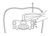
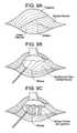
- FIGS. 9A-9CA novel triangular surgical approach window is now described, located through the confluence of three prominent cervical muscles. Now referring to FIGS. 9A-9C , the triangle is described by;
- the deep muscular layers multifide rotatoresare dissected as needed for boney exposure.
- the natural intermuscular planeextends from C2 to T1 but can be extended even further.
- Unilateral foraminal root compression and central canal stenosiscan be addressed with a unilateral approach, e.g., unilateral laminectomy or modified unilateral laminectomy allowing partial removal or thinning of the lamina under the spinous process. Additionally, this surgical approach lends itself to kyphotic deformities where removing the interspinous ligament and lagamentum flavums allows for restoration of lordosis and fusion of the facet and spinous processes. Laminoplasty can be easily accessed with the bilateral approach.
- Reconstruction optionswould include spinous process, posterior or lateral aspect of the lateral mass, facet or pedicle fixation.
- the facet complexcan be viewed laterally, permitting unique access for facet decompressions, fusion, reconstruction and instrumentation.
- This exposureavoids all the major muscle dissection of the traditional midline approach, and for MIS considerations it allows for a contiguous surgical field unlike the current application of multiple tubes/ports. Unlike current MIS tube inset techniques, this approach spares the trapezius, spenius, levator, spinalis, and most of semispinalis capitis.
- a tentcan be made by dorsally elevating the muscle fibers on the roof of the windowed opening.
- a lighted buttonis disclosed as the preferred device for making this tent, but other types of retractors can be used.
- New access instrumentsare provided for clearing and dissecting this space such as a reverse dog-bone Cobb and modular angled instruments.
- the sub-splenius accessalso leads to new implant designs that are lateral specific or unilateral.
- FIG. 1discloses a retraction instrument of the present invention.
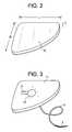
- FIG. 2discloses a retractor component of the present invention.
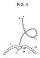
- FIG. 3discloses a retraction instrument of the present invention having a light source and battery.
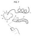
- FIG. 4discloses a retraction instrument of the present invention having a convex outer surface and a concave inner surface.
- FIG. 5discloses a retractor component of the present invention having a flexible outer rim.
- FIGS. 6 a -6 fdisclose retractor components of various shapes.
- FIGS. 7, 8 a and 8 bdisclose retraction instruments in which a wing is mated to the retractor.
- FIG. 8 cdiscloses a wing of the retraction instrument.
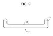
- FIG. 9discloses a plate having an outer rim and an interior region 73 , wherein the interior region of the plate defines a plane, wherein the outer rim of the plate extends out of the plane of the plate.
- FIGS. 9A-9Cdisclose views of the access region of the present invention
- FIG. 10discloses the trajectories of conventional approaches to the cervical spine.
- FIG. 11discloses the trajectories of approaches to the cervical spine providing by the present invention.
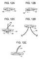
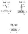
- FIGS. 12 a -12 mdisclose a number of different embodiments involving the retractor of the present invention with additional performance-enhancing features attached thereto.
- FIGS. 13 a -13 pdisclose a number of different embodiments involving the retractor of the present invention with additional support features attached thereto.
- FIGS. 14-33disclose an apparatus of the present invention involved in making a working cavity.
- FIGS. 34 a - cdisclose articulating instruments that can be used in carrying out the present invention.
- a surgical procedurecomprising the steps of:
- This procedureprovides the surgeon with a minimally invasive method of accessing the cervical spine via a posteriorlateral corridor that produces very little trauma because it takes novel advantage of a tissue plane between these muscles unilateral or bilateral. Accordingly, the superficial and intermediate layers of the cervical spine are completely avoided while the deep layers of the cervical spine bear only minimal disruption.
- manipulation of the spineis carried out between the second cervical and first thoracic vertebra, possibly T2.
- the spinal manipulationis carried out with an instrument such as a retractor.
- the retractorcan be used to increase the access window made by moving the splenius capitis and trapezius muscles dorsally.
- the retractorcomprises a plate connected to a needle by a suture. Once this retractor has been passed into the window, the needle is passed outward through the trapezius and splenius muscle and through the skin of the patient. The needle is then pulled away from the skin to make the suture taut and thereby retract the skin of the patient away from a selected tissue of the patient and create an operative space therebetween.
- the device that passes through the windowcan be an implant.
- the implantis selected from the group consisting of a screw, a cervical plate, a fusion cage and a motion disc rod, facet or lateral mass clamp.
- the procedurefurther comprises the step of removing a flavum selected from the group consisting of the interspinous flavum and the ligamentum flavum. Removing a flavum allows for access to the spinal canal, and decompression or correcting lordosis.
- the procedurefurther comprises the step of manipulating a facet joint complex through the window.
- Common procedures involving the facet jointthat can be carried out through this procedure include arthrodesis partial distraction, facetectomy, reduction of dislocation, transfacet fixation, and tumor removal.
- the step of moving the targeted musclescomprises elevating the muscles with a balloon, table-based retractor.
- the surgeonmay perform the tissue plane dissection from a sitting position. Thereafter, the surgeon may be able to carry out subsequent steps, such as manipulating the spine, from the same sitting position.
- the tissue plane dissection stepcomprises the step of releasing a deep fascia between the splenius and levator scapulae muscles. This may be accomplished by digital dissection, scissors, and harmonic tools.
- the tissue plane dissection stepcomprises the step of releasing insertions of multifidi and some portion of semispinalis from the dorsal lateral mass, laminae and spinous process bases, proceeding from lateral to medial. This may be accomplished by Cobb elavator, harmonic or other energy tool such as a bovie.
- the released multifidus, along with the spleniusare lifted upwards dorsally to maintain the operative space. This dorsal upward lifting of the multifidus may be carried out by a retractor and under illumination from a light inside the patient.
- the splenius capitis and trapezius musclesare accessed posterolaterally.
- a surgical procedurecomprising the steps of:
- a surgical procedurecomprising the steps sequential of:
- the step of retractingis performed with a plate having an outer surface, wherein the outer surface bears against one of the splenius captious and the levator scapulae.
- the step of retractingis performed by pulling the plate via the needle and suture method discussed above in one or multiple vectors.
- this procedurefurther comprises the step of irradiating the window with light from a light source in order to improve the visibility of the surgeon in the deep spine region.
- the light sourcecan be located in the window to provide a high level of brightness upon the spinal area.
- the light sourceis attached to the retraction plate and may also include camera tracking devices.
- a surgical procedurecomprising the sequential steps of:
- a surgical procedurecomprising the steps of:
- the step of pullingretracts only the first tissue and creates an expanded window.
- the present inventorshave recognized that both sides of the window need not be retracted—that assymetrically retracting the window will be sufficient and reduce tissue trauma.
- the first and second tissuesare muscles, such as the splenius capitis and levator scapulae muscles. These are the muscles that define the initial approach window.
- the step of pullingcauses the outer surface of the plate to bear against the first tissue. This differs from the conventional means of retraction in which the tissue are pushed instead of pulled.
- the step of pullingis accomplished by magnetic attraction.
- the step of pullingis accomplished by pulling a ligament attached to the retractor.
- the step of pullingis accomplished by suction. After this retraction, the procedure typically further comprises the step of:manipulating the spine of the patient through the window.
- the preferred medical retraction instrument of the present inventioncomprises a retractor 1 connected to a needle 3 by a suture 5 .
- the needlehas a distal end portion 7 that is curved. This curve advantageously provides ease of insertion point and a dorsalward direction. In some embodiments, substantially the entire needle is curved.
- the retractoris in the form of a plate 9 and has a width W, a length L and a thickness T, wherein the thickness is substantially less than each of the width and length.
- the surgical instrument passing through the windowcomprises a light with or without camera.
- the retractorhas an inner surface 11 and a convex outer surface 13 , wherein the suture 5 extends from the outer surface and wherein the instrument further comprises a light source 15 connected to the inner surface.
- the provision of the light source on the inner surfaceallows the light to shine upon the spinal region.
- the inner surface 11 of the retractor plateis made of a reflective surface in order to better disperse the light emitted by the light source upon the window.
- the light sourcecomprises an LED. Because LEDs are available in small sizes but provide high intensity light, LEDs constitute a preferred method of lighting.
- the light sourcefurther comprises a battery 17 connected to the LED, thereby eliminating any electrical wires from the design that may clutter up the operating theatre.
- the suture 5may be adapted to transmit light to the inner surface of the component. This embodiment allows for the desired lighting while providing for an inexpensive instrument design.
- the outer surface 13is convex. This convexity allows the retractor to form a tent of the window border, thereby increasing surgeon visibility into the spinal area.
- the retractorhas an outer rim 19 and an interior region 21 , wherein the outer rim comprises a flexible material.
- the flexible materialallows more physiologic edge loading of muscle tissue.
- the width and length of the retractordefine an area selected from the group consisting of a substantially circular area; a substantially oval area; a star-shaped area; a substantially triangular area; a substantially rectangular area and a kidney bean area.
- the oval areais a preferred embodiment because it better fits the elongated opening typically made by the incision.
- a kidney bean shapemay be used to clear the spinus process.
- the retractordefines an area of between about 4 cm 2 to about 16 cm 2 .
- the retractorhas an outer rim and an interior, wherein the outer rim comprises a first mating feature 23 .
- This mating featuremay be connected to a second mating feature 25 on a second component 27 , such as a wing.
- the wing or extensionprovides for extra retraction area with a minimum of added bulk and ability to extend or reduce field of retraction without repositioning the suture.
- the retraction platecomprises a polymer. If the plate is made substantially from a polymer, its cost may be so insubstantial that it may be deemed a one-use disposable.
- a medical retraction instrumentcomprising:
- the distal head of the elongated wingcontacts the inner surface of the plate. This allows the head to swivel to adjustable and fixed angles.
- the proximal end portion of the elongated winghas a throughhole 57 .
- This througholecan be used to add further wings to supporting sutures.
- the shaftwidens from the distal head to the proximal end portion. The widening of the shaft allows for broader muscle retraction.
- each throughhole of the platedefines an inner rim 59 of the plate, wherein each inner rim has a recess 61 .
- the recesses of the inner rimsoppose each other, thereby providing the elongated wings with an easy securement from either left or right (superior/inferior) directions.
- the shaft of the elongated wingextends from the outer surface of the plate. Because it extends from the outer surface of the plate, the wing provides an extended level of retraction in the directions needed as the surgery progresses from level to level.
- the shaft of the elongated wingdefines a longitudinal axis A and the distal head is off-axis.
- the off-axis nature of the distal headprovides a flip in connection that keeps the tissue-facing portion in line with the originally placed button.
- the shafthas an outer surface 63 and the distal head has an outer surface 65 , and the outer surface of the shaft is substantially parallel to the outer surface of the distal head.
- the first throughholehas a diameter
- the shaft of the elongated wingdefines a longitudinal axis A
- the distal head of the elongated winghas a length L H in the direction of the longitudinal axis, and wherein the length of the distal head is greater than the diameter of the first throughhole.
- the distal headhas an outer surface 65 , and the outer surface of the distal head of the elongated wing is substantially parallel to the inner surface of the plate. In this condition, the tissue-facing portion stays in line with the originally-placed button. This continues if additional wings are attached in chain-like fashion to the wing recesses 57 .
- the wingadvantageously traverses an offset to retract tissue that is not directly in line with the originally placed button.
- the plate 71has an outer rim 75 and an interior region 73 , wherein the interior region of the plate defines a plane, wherein the outer rim of the plate extends out of the plane of the plate.
- the outer rim of the plateextends out of the plane of the plate, this advantageously fixates the plate in the tissue and provides for distributing the loads on the tissue.
- a transition zone at the extents of the platecan be used to soften or tighten the grip on the tissue.
- a magneticcomprising:
- This magnetic retractorcan be placed within the window and then coupled across the patient's skin with a second magnet.
- the second magnetcan then be pulled to lift the skin and thereby create an expanded window.
- the outer surface of the platecomprises a ferromagnetic material.
- the ferromagnetic materialis either iron or a rare earth. Avoids requirement for passage of needle while allowing quick connect—disconnect for adjustment.
- the method steps of the present inventionmay be undertaken manually by a surgeon. In other embodiments, these method steps are undertaken robotically. In others, the method steps are undertaken by a mixture of manual steps and robotic steps.
- the methods of the present inventionare intended to be carried out broadly in the occiput-thoracic cervical region.
- Preferably The methods of the present inventionare intended to be carried out broadly in the C2-T1.
- T2is potentially accessible via the upper thoracic region. Above about C2, more injury would be contemplated.
- a lapascopemay be used to provide the positive pressure and the insufflation necessary to retract tissue.
- the unilateral laminectomy with spinous process fixationthat can be achieved through this approach has a comparable biomechanical stability to uniulateral lateral mass screws and unilateral pedicle screw fixation. It also approaches the stability provided by bilateral lateral mass screw fixation, which is considered to be the standard of care today.
- FIGS. 12( FIGS. 12 )
- FIGS. 12 a -12 mthere are provided a number of different embodiments involving the retractor of the present invention with additional performance-enhancing features attached thereto.
- the retractor 101is provided with a light emitting device 103 . This diode can increase the surgeon's visibility of the working environment with the cavity.
- the retractor 101is provided with a telescopic extension 104 that slides outwards to extend the reach of the retractor, thereby widening the footprint of the cavity.
- the refractor 101is provided with a number of irrigation and suction options, including an irrigation tube 105 having an irrigation port 107 , and a suction tube 106 having a suction port 108 . These options allow the surgeon to use irrigation fluid within the cavity, thereby assisting in cleaning the cavity of loose tissue.
- FIG. 12 athe retractor 101 is provided with a light emitting device 103 . This diode can increase the surgeon's visibility of the working environment with the cavity.
- the retractor 101is provided with a telescopic extension 104 that slides outwards to extend the reach of the retractor, thereby widening the footprint of the cavity.
- the refractor 101is provided with
- the retractor 101is provided with supporting legs 109 that hold open the cavity made by the retractor. This enhances or stabilizes the volume of the cavity.
- the retractor 101is connected to a suture 110 that passes through the patient's skin 102 . When the suture is tensioned from outside the patient, it enhances or stabilizes the volume of the cavity.
- the retractor 101is radiolucent and is provided with a radiopaque marker 111 that allows the retractor to be located on an x-ray.
- the retractor 101is provided with both a suture 110 and a fiberoptic cable 112 .
- the retractor 101is provided with a light-emitting coating 113 , such as a phosphorescent (glow-in-the dark) coating.
- the retractor 101is provided with a neuromonitoring feature 114 (such as an electrode) connected to an electrical cable 115 .
- the electrodecan help the surgeon detect nervous tissue in the vicinity of the cavity.
- the retractor 101is provided with temperature/pressure controls, such as sensor 116 (which can be either a temperature or pressure sensor) connected to an electrical cable 115 .
- a pressure sensorcan help the surgeon determine whether the retractor is imparting an unsuitably high pressure or stress upon the tissue surrounding the cavity.
- the retractor 101is provided with a strain gauge sensor 117 for measuring tension, wherein the sensor is connected to a suture 110 and an electrical cable 115 .
- the retractor 101is provided with spring scale 118 for measuring force, wherein the spring scale is connected to a suture 110 .
- the retractor 101is provided with an anti-infective coating 119 . This coating helps prevent bacteria from moving from the retractor to the patient's tissue, thereby preventing infections.
- FIGS. 13 a -13 mthere are provided a number of different embodiments involving the retractor of the present invention with additional support features attached thereto.
- the retractor 101is provided with support from inside the cavity by a C-shaped clip 120 .
- the retractor 101is provided with support from inside the cavity by a gear/rack type telescopic arch 121 .
- the refractor 101is provided with support from inside the cavity by a jack-type telescopic column 122 .
- the retractor 101is provided with support from inside the cavity by an inflatable arch 123 (providing tent-like support).
- the retractor 101is provided with support from inside the cavity by a circumferential spring sheet 124 .
- FIG. 13 athe retractor 101 is provided with support from inside the cavity by a circumferential spring sheet 124 .
- the retractor 101is provided with support from inside the cavity by a dual rack retractor blade assembly 125 .
- the retractor 101is provided with support from inside the cavity coil spring 126 .
- the retractor 101is provided with support from inside the cavity by a memory metal-based spring 127 (made of, for example, nitinol).
- the retractor 101is provided with support from inside the cavity by coil springs 129 connected by a beam 128 .
- the refractor 101is provided with support from inside the cavity by folding legs 130 connected by a beam 128 .
- FIG. 13 jthe refractor 101 is provided with support from inside the cavity by folding legs 130 connected by a beam 128 .
- the metallic retractor 101holds the cavity open via attraction to a magnet 131 located outside the patient.
- the cavityis held open with tension from outside the patient (via suture 110 ) and with a wall type anchor having two legs disposed inside the cavity.
- the anchorcomprises a threaded anchor portion 125 and a folding anchor linkage 126 .
- the cavityis held open with tension from outside the patient (via suture 110 ) and with a wall type anchor having a single leg disposed inside the cavity.
- the anchor 127comprises a toggle leg 128 .
- the cavityis held open with tension from outside the patient (via suture 110 ) through the use of adhesive tape 129 .
- FIG. 13 nthe cavity is held open with tension from outside the patient (via suture 110 ) through the use of adhesive tape 129 .
- the retractor 101is provided with support from inside the cavity by a telescopic tube 130 a secured by a set screw 103 b .
- the tube portionsare slid apart and then held in place.
- the retractor 101is provided with support from inside the cavity by cervical refractor-type device 131 .
- the patientis positioned prone, but the surgeon is comfortably sitting.
- This approachcan be unilateral or bilateral, normally for access up to C 2 -T 1 .
- a longitudinal skin incisionis based on the lateral boarder of the Trapezius, preferably in the range of 20-30 mm long and radiographically localized if needed.
- the superficial fasciais opened (20-85 mm or more) preferably with Metz along the lateral Trapezius boarder in the rage of (30-35 mm).
- the Levator scapulaeis digitally identified laterally, and the deep fascia opened between the Splenius and Levator scapulae muscle. This plane can be opened bluntly with finger dissection or with metz from 10 mm (up to 150 mm) as needed.
- the Spinal Accessory nerveis safe, resting anteriorly and laterally on the anterior boarder of Levator Scapulae, and is not retracted or involved in the approach.
- Blunt digital dissectionis directed straight medially and quickly identifies the lateral mass and the dorso-lateral corner of the facet joint. Confirmation of desired spinal level is done under direct or assisted visualization, palpation (e.g. finger sensing) and radiographically.
- the facet capsulescan be spared or removed as indicated.
- the Nuchal, interspinous and supraspinous ligamentsare preserved, as well as ligamentum flavum, and all major muscle groups.
- the multifidus, along with the splenius, semispinalis and trapeziusare lifted upwards dorsally with either standard or special retractors with or without illumination port to maintain the operative space.
- the retractionis not a typical opposed bidirectional system, but has a single multidirectional vector which puts no pressure on anterior structures.
- Complete posterior boney exposurecan extend unilaterally from the spinus process base medially across the lamina and facet to the lateral surface of the lateral mass. This entire dissection is all done unilaterally and many pathologies could be addressed without disturbing the contralateral tissues.
- the entire spinius process and interspinious spacecan be accessed laterally by dissecting the spinalis. If needed, bilateral exposure can be accomplished through a matching skin incision on the other side, and the left and right surgical fields could be connected across the midline. Closure requires 1-2 sutures in the deep fascia, 2-3 sutures in the superficial fascia and a subcuticular skin closure. There is no muscle or ligamentous reattachment required. It is possible that this dissection would allow same day discharge.
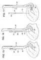
- FIG. 14 of the disclosureshows an operative window opening O being held open by a device of the present invention during surgery.
- the skinhas been incised to create the opening O
- a chandelier-type retractor(not shown in FIG. 14 ) has been inserted through the opening below the tissue to be retracted, and a punch 205 with attached suture 110 is being used to lift the chandelier (and thereby the tissue) to create a working cavity.
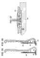
- a surgeonloads the correct size chandelier-type retractor 203 onto a channel 118 in the distal portion 204 of the holder 201 as shown in FIGS. 17 and 18 .
- the Chandelier-type retractor 203is then inserted into the operative window opening O, as shown in FIG. 15 .
- the punch 205 and the punch sled 207are plunged proximally-to-distally so that the punch point 209 makes a definitive connection with the chandelier 203 .
- the punch 205 and punch sled 207are pulled distally to proximally, leaving a trailing amount of the suture 110 , as shown in FIG. 16 and FIG. 20 . This is shown in cross-section in FIGS. 28 thru 30 .
- the suture 110is allowed to trail behind due to the excess suture available, pre-packed or wound within the punch 205 , as shown in FIG. 31 .
- the suture 110reaches a limiting length so that the punch 205 can be used to tension the chandelier 203 .
- the punch and punch sledcan be disconnected from the holder 201 , and the distal portion of the holder can be removed from the window, as shown in FIG. 17 .
- the holdercan then be manipulated by an operating room attendant or it can be parked upon a frame that supports the holder at the correct vector above the operating window.
- the framecan be fixed to the surgical bed on a rail or post arm or can be fixed to any operating room stand, hook, or pole.
- the chandelier 203may have a light.
- the lighted portion of the chandeliermay be actuated by battery connection.
- the chandelierconsists of a bi-polar receptacle 210 at its center with circuitry leading to LED lamps 211 .
- the point 209 of the punch 205has a two-conductor geometry similar to a common head phone jack as shown in FIG. 27 .
- the plus and minus wires 221 from the batteries 223( FIGS. 31 and 32 ) are incorporated into the suture 110 ( FIG. 32 ) and connected respectively to each of the conductor poles.
- the battery powertravels through the receptacle and the chandelier lights turn on.
- the batteriesare stored within the punch. However, the batteries can also be sealed within the chandelier and turned on with a switch or by removing a sterile insulating strip between the batteries. In this manner, the suture would not need to incorporate electrical wiring—it would need only support the retraction forces.
- the methods of the present inventionmay find utility in the following surgical procedures:
- Unilateral foraminal nerve root compressioncan be addressed with a unilateral foraminotomy and central canal stenosis and/or posterior ligament ossifications (PLL) causing myelopathy can also be addressed by a multilevel unilateral laminectomy with or without partial removal or thinning of the lamina under the spinous process centrally and stabilization with unilateral facet screw fixation, laminoplasty plates/screws, pedicle or lateral mass screw/rod fixation or even spinous process screws/rod or plate fixation.
- PLLposterior ligament ossifications
- Unilateral laminectomy and laminoplastycan be easily accessed with the bilateral approach. Far lateral dissection anterior to the lateral mass could provide access to the post foraminal roots and plexus if needed. Reconstructive options would include laminoplasty screws/plates, spinous process, lateral mass, or pedicle fixation. The facet complex can be viewed laterally permitting unique access for facet decompression, as well as fusion, reconstructions and instrumentation if needed.
- FIGS. 34 a - cthere are provided articulating instruments that can be used in carrying out the present invention.
- the working tips of these instrumentscan be a driver 301 , an awl 302 and a drill 303 .
- this exposureavoids all major muscle dissection of the traditional posterior midline approach, and for MIS considerations it allows for a contiguous surgical field unlike the current application of multiple tubes/ports.
- No vital structuresare presented in route, and there appear to be no catastrophic potential risks as exist with anterior approach.
- the approachis, relatively quick and may be carried out from a comfortable sitting position for operating team providing ergonomic improvement for the surgeon.
- the approachoften only be needed unilaterally to preserve function.
Landscapes
- Health & Medical Sciences (AREA)
- Life Sciences & Earth Sciences (AREA)
- Surgery (AREA)
- General Health & Medical Sciences (AREA)
- Public Health (AREA)
- Veterinary Medicine (AREA)
- Nuclear Medicine, Radiotherapy & Molecular Imaging (AREA)
- Animal Behavior & Ethology (AREA)
- Molecular Biology (AREA)
- Engineering & Computer Science (AREA)
- Biomedical Technology (AREA)
- Heart & Thoracic Surgery (AREA)
- Medical Informatics (AREA)
- Pathology (AREA)
- Biophysics (AREA)
- Radiology & Medical Imaging (AREA)
- Physics & Mathematics (AREA)
- Optics & Photonics (AREA)
- Orthopedic Medicine & Surgery (AREA)
- Oral & Maxillofacial Surgery (AREA)
- Surgical Instruments (AREA)
Abstract
Description
- a) the anterior superior border of the trapezius muscle;
- b) the anterior inferior border of the splenius capitus muscle, and
- c) the posterior superior border of the levator scapulae muscle.
- a) moving (preferably by lifting) the splenius capitus and trapezius muscles dorsally to create a window for deep spine access, wherein the window is defined by:
- i) an anterior superior border of the trapezius muscle;
- ii) an anterior inferior border of the splenius capitis muscle, and
- iii) a posterior superior border of the levator scapulae muscle,
- b) passing a device through the window, and
- c) manipulating the spine with the device.
- a) dissecting the inter-muscular plane anterior to the splenius muscle to create a window, and
- b) passing a device through the window.
- a) dissecting a sub-splenius capitis/supra-levator scapulae tissue plane to create a window,
- b) passing a device through the window,
- c) manipulating the spine with the device, and
- d) retracting one of the splenius captious and the levator scapulae to create an expanded window which forms the opening of a cave.
- a) passing a retraction instrument inward through an incision in the skin of the patient to a location adjacent a selected tissue, wherein the retraction instrument comprises a plate connected to a needle by a suture,
- b) passing the needle outward through the skin of the patient;
- c) pulling the needle away from the skin to tension the suture and thereby retract the skin of the patient away from the selected tissue.
- a) dissecting an inter-tissue plane defined by a first tissue and a second tissue to create a window,
- b) inserting a retractor into the window,
- c) pulling the retractor in the direction of the first tissue
- a) a
plate 31 having aninner surface 33 andouter surface 35 and a pair ofthroughholes 37, - b) a suture41 having first43 and second45 ends,
- c) first and
second needles 47, - d) an
elongated wing 49 having adistal head 51, ashaft 53 and aproximal end portion 55, - wherein the suture passes through the first throughhole in a first direction and through the second through is an opposite direction,
- wherein the first needle is connected to the first end of the suture,
- wherein the second needle is connected to the second end of the suture, and
- wherein the distal head of the elongated wing is passed through the first throughhole.
- a) a ferromagnetic plate having an inner surface and an outer surface,
- b) a light source attached to the inner surface of the plate,
- 1. Cervical laminectomy: used for cervical stenosis (congenital and acquired), cervical spondylotic myelopathy, multilevel spondylotic radiculopathy, ossification of the posterior longitudinal ligament (OPLL), ossification of the yellow ligament (OYL), neoplasm, and infection. MIS unilateral decompression using laminectomy and posterior cervical stabilization and fusion can be achieved using either:
- a) Pedicle screws/rods fixation
- b) Spinous process screws/rods or plate fixation
- c) Translaminar plates/screws fixation
- d) Lateral screws/rods fixation
- e) Facet screws
- f) Bilateral laminectomy/Laminoplasty
- 2. Single level foraminotomy for radiculopathy (including unilateral foraminotomy and unilateral facetectomy);
- 3. Posterior element tumor resection;
- 4. Brachial Plexus Surgery;
- 5. ORIF Cervical Fracture; and
- 6. Posterior Cervical Fixation (traditional lateral mass/cranio-thoracic).
Claims (20)
Priority Applications (14)
| Application Number | Priority Date | Filing Date | Title |
|---|---|---|---|
| US13/627,294US9622779B2 (en) | 2011-10-27 | 2012-09-26 | Method and devices for a sub-splenius / supra-levator scapulae surgical access technique |
| PCT/US2012/060754WO2013062845A2 (en) | 2011-10-27 | 2012-10-18 | Method and devices for a sub-splenius / supra-levator scapulae surgical access technique |
| EP12784394.4AEP2770915B1 (en) | 2011-10-27 | 2012-10-18 | Devices for a sub-splenius / supra-levator scapulae surgical access technique |
| US15/469,912US10695093B2 (en) | 2011-10-27 | 2017-03-27 | Method and devices for a sub-splenius/supra-levator scapulae surgical access technique |
| US16/125,398US11911017B2 (en) | 2011-10-27 | 2018-09-07 | Method and devices for a sub-splenius/supra-levator scapulae surgical access technique |
| US16/125,444US20190083143A1 (en) | 2011-10-27 | 2018-09-07 | Method and Devices for a Sub-Splenius/Supra-Levator Scapulae Surgical Access Technique |
| US16/125,375US11134987B2 (en) | 2011-10-27 | 2018-09-07 | Method and devices for a sub-splenius/supra-levator scapulae surgical access technique |
| US16/125,390US11241255B2 (en) | 2011-10-27 | 2018-09-07 | Method and devices for a sub-splenius/supra-levator scapulae surgical access technique |
| US16/125,418US11278323B2 (en) | 2011-10-27 | 2018-09-07 | Method and devices for a sub-splenius/supra-levator scapulae surgical access technique |
| US16/125,430US20190083141A1 (en) | 2011-10-27 | 2018-09-07 | Method and Devices for a Sub-Splenius/Supra-Levator Scapulae Surgical Access Technique |
| US16/125,424US11234736B2 (en) | 2011-10-27 | 2018-09-07 | Method and devices for a sub-splenius/supra-levator scapulae surgical access technique |
| US16/125,412US20190008560A1 (en) | 2011-10-27 | 2018-09-07 | Method and Devices for a Sub-Splenius/Supra-Levator Scapulae Surgical Access Technique |
| US16/125,437US20190083142A1 (en) | 2011-10-27 | 2018-09-07 | Method and Devices for a Sub-Splenius/Supra-Levator Scapulae Surgical Access Technique |
| US16/733,016US11937797B2 (en) | 2011-10-27 | 2020-01-02 | Method and devices for a sub-splenius/supra-levator scapulae surgical access technique |
Applications Claiming Priority (3)
| Application Number | Priority Date | Filing Date | Title |
|---|---|---|---|
| US201161552433P | 2011-10-27 | 2011-10-27 | |
| US201261663074P | 2012-06-22 | 2012-06-22 | |
| US13/627,294US9622779B2 (en) | 2011-10-27 | 2012-09-26 | Method and devices for a sub-splenius / supra-levator scapulae surgical access technique |
Related Child Applications (2)
| Application Number | Title | Priority Date | Filing Date |
|---|---|---|---|
| US15/469,912DivisionUS10695093B2 (en) | 2011-10-27 | 2017-03-27 | Method and devices for a sub-splenius/supra-levator scapulae surgical access technique |
| US15/469,912ContinuationUS10695093B2 (en) | 2011-10-27 | 2017-03-27 | Method and devices for a sub-splenius/supra-levator scapulae surgical access technique |
Publications (2)
| Publication Number | Publication Date |
|---|---|
| US20130109925A1 US20130109925A1 (en) | 2013-05-02 |
| US9622779B2true US9622779B2 (en) | 2017-04-18 |
Family
ID=47172893
Family Applications (12)
| Application Number | Title | Priority Date | Filing Date |
|---|---|---|---|
| US13/627,294Active2034-05-07US9622779B2 (en) | 2011-10-27 | 2012-09-26 | Method and devices for a sub-splenius / supra-levator scapulae surgical access technique |
| US15/469,912ActiveUS10695093B2 (en) | 2011-10-27 | 2017-03-27 | Method and devices for a sub-splenius/supra-levator scapulae surgical access technique |
| US16/125,375ActiveUS11134987B2 (en) | 2011-10-27 | 2018-09-07 | Method and devices for a sub-splenius/supra-levator scapulae surgical access technique |
| US16/125,398Active2035-04-12US11911017B2 (en) | 2011-10-27 | 2018-09-07 | Method and devices for a sub-splenius/supra-levator scapulae surgical access technique |
| US16/125,390ActiveUS11241255B2 (en) | 2011-10-27 | 2018-09-07 | Method and devices for a sub-splenius/supra-levator scapulae surgical access technique |
| US16/125,444AbandonedUS20190083143A1 (en) | 2011-10-27 | 2018-09-07 | Method and Devices for a Sub-Splenius/Supra-Levator Scapulae Surgical Access Technique |
| US16/125,437AbandonedUS20190083142A1 (en) | 2011-10-27 | 2018-09-07 | Method and Devices for a Sub-Splenius/Supra-Levator Scapulae Surgical Access Technique |
| US16/125,412AbandonedUS20190008560A1 (en) | 2011-10-27 | 2018-09-07 | Method and Devices for a Sub-Splenius/Supra-Levator Scapulae Surgical Access Technique |
| US16/125,430AbandonedUS20190083141A1 (en) | 2011-10-27 | 2018-09-07 | Method and Devices for a Sub-Splenius/Supra-Levator Scapulae Surgical Access Technique |
| US16/125,418Active2033-06-16US11278323B2 (en) | 2011-10-27 | 2018-09-07 | Method and devices for a sub-splenius/supra-levator scapulae surgical access technique |
| US16/125,424Active2033-06-23US11234736B2 (en) | 2011-10-27 | 2018-09-07 | Method and devices for a sub-splenius/supra-levator scapulae surgical access technique |
| US16/733,016Active2032-11-11US11937797B2 (en) | 2011-10-27 | 2020-01-02 | Method and devices for a sub-splenius/supra-levator scapulae surgical access technique |
Family Applications After (11)
| Application Number | Title | Priority Date | Filing Date |
|---|---|---|---|
| US15/469,912ActiveUS10695093B2 (en) | 2011-10-27 | 2017-03-27 | Method and devices for a sub-splenius/supra-levator scapulae surgical access technique |
| US16/125,375ActiveUS11134987B2 (en) | 2011-10-27 | 2018-09-07 | Method and devices for a sub-splenius/supra-levator scapulae surgical access technique |
| US16/125,398Active2035-04-12US11911017B2 (en) | 2011-10-27 | 2018-09-07 | Method and devices for a sub-splenius/supra-levator scapulae surgical access technique |
| US16/125,390ActiveUS11241255B2 (en) | 2011-10-27 | 2018-09-07 | Method and devices for a sub-splenius/supra-levator scapulae surgical access technique |
| US16/125,444AbandonedUS20190083143A1 (en) | 2011-10-27 | 2018-09-07 | Method and Devices for a Sub-Splenius/Supra-Levator Scapulae Surgical Access Technique |
| US16/125,437AbandonedUS20190083142A1 (en) | 2011-10-27 | 2018-09-07 | Method and Devices for a Sub-Splenius/Supra-Levator Scapulae Surgical Access Technique |
| US16/125,412AbandonedUS20190008560A1 (en) | 2011-10-27 | 2018-09-07 | Method and Devices for a Sub-Splenius/Supra-Levator Scapulae Surgical Access Technique |
| US16/125,430AbandonedUS20190083141A1 (en) | 2011-10-27 | 2018-09-07 | Method and Devices for a Sub-Splenius/Supra-Levator Scapulae Surgical Access Technique |
| US16/125,418Active2033-06-16US11278323B2 (en) | 2011-10-27 | 2018-09-07 | Method and devices for a sub-splenius/supra-levator scapulae surgical access technique |
| US16/125,424Active2033-06-23US11234736B2 (en) | 2011-10-27 | 2018-09-07 | Method and devices for a sub-splenius/supra-levator scapulae surgical access technique |
| US16/733,016Active2032-11-11US11937797B2 (en) | 2011-10-27 | 2020-01-02 | Method and devices for a sub-splenius/supra-levator scapulae surgical access technique |
Country Status (3)
| Country | Link |
|---|---|
| US (12) | US9622779B2 (en) |
| EP (1) | EP2770915B1 (en) |
| WO (1) | WO2013062845A2 (en) |
Cited By (6)
| Publication number | Priority date | Publication date | Assignee | Title |
|---|---|---|---|---|
| US20180280109A1 (en)* | 2017-03-31 | 2018-10-04 | Mindskid Labs, Llc | Apparatus for illuminating an eye related application |
| US10166020B2 (en) | 2009-12-04 | 2019-01-01 | Pivot Medical, Inc. | Methods and devices for accessing and retracting a capsule of a joint |
| US20200179007A1 (en)* | 2011-10-27 | 2020-06-11 | DePuy Synthes Products, Inc. | Method and devices for a sub-splenius/supra-levator scapulae surgical access technique |
| US11033341B2 (en) | 2017-05-10 | 2021-06-15 | Mako Surgical Corp. | Robotic spine surgery system and methods |
| US11065069B2 (en) | 2017-05-10 | 2021-07-20 | Mako Surgical Corp. | Robotic spine surgery system and methods |
| US12171419B2 (en) | 2021-10-06 | 2024-12-24 | K2M, Inc. | Offset Hohmann |
Families Citing this family (28)
| Publication number | Priority date | Publication date | Assignee | Title |
|---|---|---|---|---|
| WO2008070863A2 (en) | 2006-12-07 | 2008-06-12 | Interventional Spine, Inc. | Intervertebral implant |
| US8936641B2 (en) | 2008-04-05 | 2015-01-20 | DePuy Synthes Products, LLC | Expandable intervertebral implant |
| US9526620B2 (en) | 2009-03-30 | 2016-12-27 | DePuy Synthes Products, Inc. | Zero profile spinal fusion cage |
| US9028553B2 (en) | 2009-11-05 | 2015-05-12 | DePuy Synthes Products, Inc. | Self-pivoting spinal implant and associated instrumentation |
| US9393129B2 (en) | 2009-12-10 | 2016-07-19 | DePuy Synthes Products, Inc. | Bellows-like expandable interbody fusion cage |
| US8376937B2 (en)* | 2010-01-28 | 2013-02-19 | Warsaw Orhtopedic, Inc. | Tissue monitoring surgical retractor system |
| US9907560B2 (en) | 2010-06-24 | 2018-03-06 | DePuy Synthes Products, Inc. | Flexible vertebral body shavers |
| US8979860B2 (en) | 2010-06-24 | 2015-03-17 | DePuy Synthes Products. LLC | Enhanced cage insertion device |
| US8623091B2 (en) | 2010-06-29 | 2014-01-07 | DePuy Synthes Products, LLC | Distractible intervertebral implant |
| US9888920B2 (en) | 2010-09-21 | 2018-02-13 | Sportwelding Gmbh | Connecting a plurality of tissue parts |
| US9402732B2 (en) | 2010-10-11 | 2016-08-02 | DePuy Synthes Products, Inc. | Expandable interspinous process spacer implant |
| EP3485851B1 (en) | 2011-03-22 | 2021-08-25 | DePuy Synthes Products, LLC | Universal trial for lateral cages |
| US9226764B2 (en) | 2012-03-06 | 2016-01-05 | DePuy Synthes Products, Inc. | Conformable soft tissue removal instruments |
| US10022245B2 (en) | 2012-12-17 | 2018-07-17 | DePuy Synthes Products, Inc. | Polyaxial articulating instrument |
| US9717601B2 (en) | 2013-02-28 | 2017-08-01 | DePuy Synthes Products, Inc. | Expandable intervertebral implant, system, kit and method |
| US9522070B2 (en) | 2013-03-07 | 2016-12-20 | Interventional Spine, Inc. | Intervertebral implant |
| US11426290B2 (en) | 2015-03-06 | 2022-08-30 | DePuy Synthes Products, Inc. | Expandable intervertebral implant, system, kit and method |
| US11510788B2 (en) | 2016-06-28 | 2022-11-29 | Eit Emerging Implant Technologies Gmbh | Expandable, angularly adjustable intervertebral cages |
| EP3474784A2 (en) | 2016-06-28 | 2019-05-01 | Eit Emerging Implant Technologies GmbH | Expandable and angularly adjustable intervertebral cages with articulating joint |
| US10398563B2 (en) | 2017-05-08 | 2019-09-03 | Medos International Sarl | Expandable cage |
| US11344424B2 (en) | 2017-06-14 | 2022-05-31 | Medos International Sarl | Expandable intervertebral implant and related methods |
| US10966843B2 (en) | 2017-07-18 | 2021-04-06 | DePuy Synthes Products, Inc. | Implant inserters and related methods |
| CN111031946A (en)* | 2017-08-09 | 2020-04-17 | 爱尔康公司 | Self-illuminating microsurgical intubation device |
| US11045331B2 (en) | 2017-08-14 | 2021-06-29 | DePuy Synthes Products, Inc. | Intervertebral implant inserters and related methods |
| US11446156B2 (en) | 2018-10-25 | 2022-09-20 | Medos International Sarl | Expandable intervertebral implant, inserter instrument, and related methods |
| US11426286B2 (en) | 2020-03-06 | 2022-08-30 | Eit Emerging Implant Technologies Gmbh | Expandable intervertebral implant |
| US11850160B2 (en) | 2021-03-26 | 2023-12-26 | Medos International Sarl | Expandable lordotic intervertebral fusion cage |
| US11752009B2 (en) | 2021-04-06 | 2023-09-12 | Medos International Sarl | Expandable intervertebral fusion cage |
Citations (6)
| Publication number | Priority date | Publication date | Assignee | Title |
|---|---|---|---|---|
| US20040143167A1 (en)* | 2002-08-02 | 2004-07-22 | Branch Charles L. | Systems and techniques for illuminating a surgical space |
| US20050288677A1 (en)* | 2005-10-03 | 2005-12-29 | Inventit, Llc | Spinal surgery distractor with an integrated retractor |
| US20070010716A1 (en)* | 2005-07-11 | 2007-01-11 | Malandain Hugues F | Surgical access device, system, and methods of use |
| US20090177241A1 (en)* | 2005-10-15 | 2009-07-09 | Bleich Jeffery L | Multiple pathways for spinal nerve root decompression from a single access point |
| EP2353537A1 (en) | 2008-10-31 | 2011-08-10 | Limited Liability Company Japan Medical Creative | Illumination system for surgical operation |
| WO2011116379A2 (en) | 2010-03-19 | 2011-09-22 | Mcclelan William T | Knotless locking tissue fastening system and method |
Family Cites Families (368)
| Publication number | Priority date | Publication date | Assignee | Title |
|---|---|---|---|---|
| US4573448A (en) | 1983-10-05 | 1986-03-04 | Pilling Co. | Method for decompressing herniated intervertebral discs |
| US4678459A (en) | 1984-07-23 | 1987-07-07 | E-Z-Em, Inc. | Irrigating, cutting and aspirating system for percutaneous surgery |
| US4646738A (en) | 1985-12-05 | 1987-03-03 | Concept, Inc. | Rotary surgical tool |
| US4863430A (en) | 1987-08-26 | 1989-09-05 | Surgical Dynamics, Inc. | Introduction set with flexible trocar with curved cannula |
| US5529580A (en) | 1987-10-30 | 1996-06-25 | Olympus Optical Co., Ltd. | Surgical resecting tool |
| US4888146A (en) | 1988-05-19 | 1989-12-19 | Dandeneau James V | Method and apparatus of forming extruded article |
| US5080662A (en) | 1989-11-27 | 1992-01-14 | Paul Kamaljit S | Spinal stereotaxic device and method |
| US5454365A (en) | 1990-11-05 | 1995-10-03 | Bonutti; Peter M. | Mechanically expandable arthroscopic retractors |
| US5269785A (en) | 1990-06-28 | 1993-12-14 | Bonutti Peter M | Apparatus and method for tissue removal |
| US5285795A (en) | 1991-09-12 | 1994-02-15 | Surgical Dynamics, Inc. | Percutaneous discectomy system having a bendable discectomy probe and a steerable cannula |
| IT1249714B (en) | 1991-10-11 | 1995-03-09 | Mauro Caponi | DOUBLE CANNAL SURGICAL INSTRUMENT. |
| US5195541A (en) | 1991-10-18 | 1993-03-23 | Obenchain Theodore G | Method of performing laparoscopic lumbar discectomy |
| US5395317A (en) | 1991-10-30 | 1995-03-07 | Smith & Nephew Dyonics, Inc. | Unilateral biportal percutaneous surgical procedure |
| US5329937A (en) | 1992-09-10 | 1994-07-19 | Nova Healthcare Industries, Inc. | Speculum protector with smoke tube |
| US5362294A (en)* | 1992-09-25 | 1994-11-08 | Seitzinger Michael R | Sling for positioning internal organ during laparoscopic surgery and method of use |
| US5447446A (en) | 1992-11-05 | 1995-09-05 | Thomas & Betts Corporation | Electrical connector component having secured seal |
| US5735792A (en) | 1992-11-25 | 1998-04-07 | Clarus Medical Systems, Inc. | Surgical instrument including viewing optics and an atraumatic probe |
| US6387363B1 (en) | 1992-12-31 | 2002-05-14 | United States Surgical Corporation | Biocompatible medical devices |
| US5540706A (en) | 1993-01-25 | 1996-07-30 | Aust; Gilbert M. | Surgical instrument |
| US5439464A (en) | 1993-03-09 | 1995-08-08 | Shapiro Partners Limited | Method and instruments for performing arthroscopic spinal surgery |
| US5387220A (en) | 1993-06-15 | 1995-02-07 | Pisharodi; Maohaven | Stereotactic frame and localization method |
| US5513827A (en) | 1993-07-26 | 1996-05-07 | Karlin Technology, Inc. | Gooseneck surgical instrument holder |
| US5588949A (en) | 1993-10-08 | 1996-12-31 | Heartport, Inc. | Stereoscopic percutaneous visualization system |
| DE9415039U1 (en) | 1994-09-16 | 1994-11-03 | Kernforschungszentrum Karlsruhe Gmbh, 76133 Karlsruhe | Device for guiding surgical instruments |
| JP3580903B2 (en)* | 1994-09-26 | 2004-10-27 | オリンパス株式会社 | Lifting equipment |
| US5562695A (en) | 1995-01-10 | 1996-10-08 | Obenchain; Theodore G. | Nerve deflecting conduit needle and method |
| US5569290A (en) | 1995-01-30 | 1996-10-29 | Paul C. McAfee | Method of and apparatus for laparoscopic or endoscopic spinal surgery using an unsealed anteriorly inserted transparent trochar |
| WO1996029014A1 (en) | 1995-03-22 | 1996-09-26 | Evi Corporation | Intra-artery obstruction clearing apparatus and methods |
| DE19520277C1 (en) | 1995-06-02 | 1996-11-21 | Winter & Ibe Olympus | Endoscopic instrument with flushing passage |
| JPH10505286A (en) | 1995-06-20 | 1998-05-26 | シン ング、ワン | Articulated arm for medical procedures |
| US5591187A (en) | 1995-07-14 | 1997-01-07 | Dekel; Moshe | Laparoscopic tissue retrieval device and method |
| US5733242A (en) | 1996-02-07 | 1998-03-31 | Rayburn; Robert L. | Intubation system having an axially moveable memory cylinder |
| DE19780707C2 (en) | 1996-03-22 | 2002-09-12 | Sdgi Holdings Inc | Percutaneous surgery device |
| US5792044A (en) | 1996-03-22 | 1998-08-11 | Danek Medical, Inc. | Devices and methods for percutaneous surgery |
| JP3819962B2 (en) | 1996-04-01 | 2006-09-13 | ペンタックス株式会社 | Interbody fusion implant guide device |
| US5967973A (en) | 1996-04-26 | 1999-10-19 | United States Surgical | Surgical retractor and method of surgery |
| DE69735146T2 (en) | 1996-05-09 | 2006-09-28 | Olympus Corporation | Surgical tool for holding a cavity |
| US7104986B2 (en) | 1996-07-16 | 2006-09-12 | Arthrocare Corporation | Intervertebral disc replacement method |
| US6322498B1 (en) | 1996-10-04 | 2001-11-27 | University Of Florida | Imaging scope |
| US6033105A (en) | 1996-11-15 | 2000-03-07 | Barker; Donald | Integrated bone cement mixing and dispensing system |
| US5894369A (en) | 1996-11-15 | 1999-04-13 | Fuji Photo Optical Co., Ltd. | Lens device with anti-fogging |
| US5928158A (en)* | 1997-03-25 | 1999-07-27 | Aristides; Arellano | Medical instrument with nerve sensor |
| US6440063B1 (en)* | 1997-04-30 | 2002-08-27 | University Of Massachusetts | Surgical access port and laparoscopic surgical method |
| US5906577A (en) | 1997-04-30 | 1999-05-25 | University Of Massachusetts | Device, surgical access port, and method of retracting an incision into an opening and providing a channel through the incision |
| US5899425A (en) | 1997-05-02 | 1999-05-04 | Medtronic, Inc. | Adjustable supporting bracket having plural ball and socket joints |
| JPH1199156A (en)* | 1997-07-29 | 1999-04-13 | Olympus Optical Co Ltd | Access device for surgical treatment |
| US6080168A (en)* | 1997-08-28 | 2000-06-27 | Levin; John M. | Compression pad for laparoscopic/thorascopic surgery |
| NL1006944C2 (en) | 1997-09-04 | 1999-03-11 | Mark Hans Emanuel | Surgical endoscopic cutting device. |
| AUPP294698A0 (en) | 1998-04-15 | 1998-05-07 | Gray, Bruce | Removable ball joint |
| US6110182A (en) | 1998-06-22 | 2000-08-29 | Ohio Medical Instruments Company, Inc. | Target socket |
| US6063021A (en) | 1998-07-31 | 2000-05-16 | Pilling Weck Incorporated | Stabilizer for surgery |
| US6042536A (en) | 1998-08-13 | 2000-03-28 | Contimed, Inc. | Bladder sling |
| US6053907A (en) | 1998-08-13 | 2000-04-25 | Endius Incorporated | Surgical instruments with flexible drive shaft |
| US6296644B1 (en) | 1998-08-26 | 2001-10-02 | Jean Saurat | Spinal instrumentation system with articulated modules |
| US6286179B1 (en) | 1998-10-19 | 2001-09-11 | Donny M. Byrne | Apparatus and method for removing debris from the lens-cleaning nozzle of an endoscope |
| US6254534B1 (en)* | 1999-10-14 | 2001-07-03 | Atropos Limited | Retractor |
| EP1146816B1 (en)* | 1998-12-23 | 2005-10-12 | Nuvasive Inc. | Nerve surveillance cannulae systems |
| US6626830B1 (en) | 1999-05-04 | 2003-09-30 | Cardiothoracic Systems, Inc. | Methods and devices for improved tissue stabilization |
| US6475139B1 (en)* | 1999-06-09 | 2002-11-05 | Ethicon, Inc. | Visually-directed surgical instrument and method for treating female urinary incontinence |
| US7637905B2 (en) | 2003-01-15 | 2009-12-29 | Usgi Medical, Inc. | Endoluminal tool deployment system |
| US20040122456A1 (en)* | 2002-12-11 | 2004-06-24 | Saadat Vahid C. | Methods and apparatus for gastric reduction |
| US6283966B1 (en) | 1999-07-07 | 2001-09-04 | Sulzer Spine-Tech Inc. | Spinal surgery tools and positioning method |
| US6200322B1 (en) | 1999-08-13 | 2001-03-13 | Sdgi Holdings, Inc. | Minimal exposure posterior spinal interbody instrumentation and technique |
| DE29916026U1 (en) | 1999-09-11 | 1999-11-18 | Aesculap AG & Co. KG, 78532 Tuttlingen | Holding device for a surgical instrument |
| US6575899B1 (en) | 1999-10-20 | 2003-06-10 | Sdgi Holdings, Inc. | Methods and instruments for endoscopic interbody surgical techniques |
| US6447446B1 (en) | 1999-11-02 | 2002-09-10 | Medtronic Xomed, Inc. | Method and apparatus for cleaning an endoscope lens |
| US6354992B1 (en) | 1999-11-08 | 2002-03-12 | Daniel T. Kato | Automated laparoscopic lens cleaner |
| US6648915B2 (en) | 1999-12-23 | 2003-11-18 | John A. Sazy | Intervertebral cage and method of use |
| US6684886B1 (en) | 2000-01-21 | 2004-02-03 | Prospine, Inc. | Intervertebral disc repair methods and apparatus |
| NL1014255C2 (en) | 2000-02-01 | 2001-08-02 | Univ Medisch Centrum Utrecht | Support arm for operating purposes. |
| US6808505B2 (en) | 2000-02-01 | 2004-10-26 | Kadan Jeffrey S | Diagnostic needle arthroscopy and lavage system |
| US6575979B1 (en) | 2000-02-16 | 2003-06-10 | Axiamed, Inc. | Method and apparatus for providing posterior or anterior trans-sacral access to spinal vertebrae |
| US20030191474A1 (en) | 2000-02-16 | 2003-10-09 | Cragg Andrew H. | Apparatus for performing a discectomy through a trans-sacral axial bore within the vertebrae of the spine |
| US20020022762A1 (en) | 2000-02-18 | 2002-02-21 | Richard Beane | Devices and methods for warming and cleaning lenses of optical surgical instruments |
| US6383191B1 (en) | 2000-03-15 | 2002-05-07 | Sdgi Holdings, Inc. | Laparoscopic instrument sleeve |
| DE10019321C2 (en) | 2000-04-19 | 2002-03-14 | Storz Karl Gmbh & Co Kg | Flexible tensioning device, in particular for medical purposes |
| DE10024728A1 (en) | 2000-05-19 | 2001-11-22 | Ami Gmbh | Unit cleaning endoscopic instrument window in-situ during intervention, comprises detachable end casing with insufflation- and flushing channels |
| AU2001270180A1 (en) | 2000-06-30 | 2002-01-14 | Abbott Laboratories | Surgical support clamp |
| US7056321B2 (en) | 2000-08-01 | 2006-06-06 | Endius, Incorporated | Method of securing vertebrae |
| US6692434B2 (en) | 2000-09-29 | 2004-02-17 | Stephen Ritland | Method and device for retractor for microsurgical intermuscular lumbar arthrodesis |
| US6579281B2 (en) | 2000-10-11 | 2003-06-17 | Popcab, Llc | Instrument stabilizer for through-a-port surgery |
| US6558407B1 (en) | 2000-10-24 | 2003-05-06 | Tyco Healthcare Group Lp | Breast stabilizer with instrument guide |
| US6676597B2 (en) | 2001-01-13 | 2004-01-13 | Medtronic, Inc. | Method and device for organ positioning |
| US6673023B2 (en) | 2001-03-23 | 2004-01-06 | Stryker Puerto Rico Limited | Micro-invasive breast biopsy device |
| US7144393B2 (en) | 2001-05-15 | 2006-12-05 | Dipoto Gene P | Structure for receiving surgical instruments |
| IL143682A0 (en) | 2001-06-11 | 2002-04-21 | Shalman Michael | Endoscope with cleaning optics |
| EP1417000B1 (en)* | 2001-07-11 | 2018-07-11 | Nuvasive, Inc. | System for determining nerve proximity during surgery |
| US7137949B2 (en) | 2001-07-13 | 2006-11-21 | United States Surgical Corporation | Surgical instrument |
| JP2005503857A (en) | 2001-09-25 | 2005-02-10 | ヌバシブ, インコーポレイテッド | Systems and methods for performing surgical procedures and surgical diagnosis |
| US6887198B2 (en) | 2001-10-05 | 2005-05-03 | Burns P. Phillips | Gooseneck surgical retractor positioner and method of its use |
| US6958037B2 (en) | 2001-10-20 | 2005-10-25 | Applied Medical Resources Corporation | Wound retraction apparatus and method |
| US20030083555A1 (en) | 2001-10-29 | 2003-05-01 | Scott Hunt | Segmented arm support system and method for stabilizing tissue |
| US7824410B2 (en) | 2001-10-30 | 2010-11-02 | Depuy Spine, Inc. | Instruments and methods for minimally invasive spine surgery |
| US6862480B2 (en)* | 2001-11-29 | 2005-03-01 | Biocontrol Medical Ltd. | Pelvic disorder treatment device |
| US7182731B2 (en) | 2002-01-23 | 2007-02-27 | Genesee Biomedical, Inc. | Support arm for cardiac surgery |
| US6896675B2 (en) | 2002-03-05 | 2005-05-24 | Baylis Medical Company Inc. | Intradiscal lesioning device |
| US20050080425A1 (en) | 2002-03-18 | 2005-04-14 | Mohit Bhatnagar | Minimally invasive bone manipulation device and method of use |
| US7112172B2 (en)* | 2002-05-17 | 2006-09-26 | Tyco Healthcare Group Lp | Endoscopic organ retraction system and method of using the same |
| US6758809B2 (en) | 2002-06-06 | 2004-07-06 | Medtronic, Inc. | Surgical tool for engagement of body tissue |
| US7582058B1 (en) | 2002-06-26 | 2009-09-01 | Nuvasive, Inc. | Surgical access system and related methods |
| US7074226B2 (en) | 2002-09-19 | 2006-07-11 | Sdgi Holdings, Inc. | Oval dilator and retractor set and method |
| US8137284B2 (en) | 2002-10-08 | 2012-03-20 | Nuvasive, Inc. | Surgical access system and related methods |
| WO2004039235A2 (en) | 2002-10-25 | 2004-05-13 | Endius Incorporated | Apparatus and methods for shielding body structures during surgery |
| EP2305812A3 (en) | 2002-11-14 | 2012-06-06 | Dharmacon, Inc. | Fuctional and hyperfunctional sirna |
| US7636596B2 (en) | 2002-12-20 | 2009-12-22 | Medtronic, Inc. | Organ access device and method |
| US7004971B2 (en) | 2002-12-31 | 2006-02-28 | Depuy Acromed, Inc. | Annular nucleus pulposus replacement |
| US7691057B2 (en)* | 2003-01-16 | 2010-04-06 | Nuvasive, Inc. | Surgical access system and related methods |
| US7819801B2 (en) | 2003-02-27 | 2010-10-26 | Nuvasive, Inc. | Surgical access system and related methods |
| US7641659B2 (en) | 2003-03-13 | 2010-01-05 | Zimmer Spine, Inc. | Spinal access instrument |
| US20040199052A1 (en) | 2003-04-01 | 2004-10-07 | Scimed Life Systems, Inc. | Endoscopic imaging system |
| US7794456B2 (en) | 2003-05-13 | 2010-09-14 | Arthrocare Corporation | Systems and methods for electrosurgical intervertebral disc replacement |
| JP2007511247A (en) | 2003-05-19 | 2007-05-10 | ユーエスジーアイ メディカル, インコーポレイテッド | Lumen tool deployment system |
| GB0315479D0 (en)* | 2003-07-02 | 2003-08-06 | Paz Adrian | Virtual ports devices |
| WO2005011476A2 (en) | 2003-07-29 | 2005-02-10 | Endoscopic Technologies, Inc. | Tissue positioner |
| US7771384B2 (en) | 2003-08-20 | 2010-08-10 | Biagio Ravo | Trocar with integral irrigation and suction tube |
| US7811303B2 (en) | 2003-08-26 | 2010-10-12 | Medicine Lodge Inc | Bodily tissue dilation systems and methods |
| JP4463819B2 (en) | 2003-09-25 | 2010-05-19 | ヌヴァシヴ インコーポレイテッド | Surgical access system |
| ES2260557T3 (en) | 2003-10-17 | 2006-11-01 | Henke-Sass, Wolf Gmbh | ENDOSCOPE |
| US7338495B2 (en) | 2003-10-22 | 2008-03-04 | Medtronic Xomed, Inc. | Angled tissue cutting instruments having flexible inner tubular members of tube and sleeve construction |
| US7946981B1 (en) | 2003-10-23 | 2011-05-24 | Anthony Cubb | Two-piece video laryngoscope |
| WO2005046516A2 (en)* | 2003-11-10 | 2005-05-26 | Angiotech International Ag | Medical implants and anti-scarring agents |
| US8038611B2 (en)* | 2003-12-18 | 2011-10-18 | Depuy Spine, Inc. | Surgical methods and surgical kits |
| US8221424B2 (en) | 2004-12-20 | 2012-07-17 | Spinascope, Inc. | Surgical instrument for orthopedic surgery |
| CA2556935A1 (en) | 2004-02-19 | 2005-09-01 | Applied Medical Resources Corporation | Embolectomy capture sheath |
| US8784421B2 (en) | 2004-03-03 | 2014-07-22 | Boston Scientific Scimed, Inc. | Apparatus and methods for removing vertebral bone and disc tissue |
| US7841978B2 (en)* | 2004-03-23 | 2010-11-30 | Michael Gertner | Methods and devices for to treatment of obesity |
| GB0411360D0 (en)* | 2004-05-21 | 2004-06-23 | Mpathy Medical Devices Ltd | Implant |
| US7407485B2 (en)* | 2004-06-08 | 2008-08-05 | Instrumentarium Corporation | Monitoring pain-related responses of a patient |
| US7150714B2 (en) | 2004-06-14 | 2006-12-19 | Ebi, L.P. | Minimally invasive surgical spinal exposure system |
| US8961407B2 (en) | 2004-07-21 | 2015-02-24 | Covidien Lp | Surgical port assembly |
| US7434325B2 (en) | 2004-07-26 | 2008-10-14 | Warsaw Orthopedic, Inc. | Systems and methods for determining optimal retractor length in minimally invasive procedures |
| US9387313B2 (en) | 2004-08-03 | 2016-07-12 | Interventional Spine, Inc. | Telescopic percutaneous tissue dilation systems and related methods |
| US8460310B2 (en) | 2004-08-04 | 2013-06-11 | Leslie Stern | Surgical base unit and retractor support mechanism |
| CA2597944A1 (en) | 2004-08-15 | 2006-02-23 | Kevin Seex | Distraction and retraction assemblies |
| EP1814472B1 (en) | 2004-09-08 | 2018-10-24 | NuVasive, Inc. | Systems for performing spinal fixation |
| US7479106B2 (en) | 2004-09-30 | 2009-01-20 | Boston Scientific Scimed, Inc. | Automated control of irrigation and aspiration in a single-use endoscope |
| WO2006042241A2 (en)* | 2004-10-08 | 2006-04-20 | Nuvasive, Inc. | Surgical access system and related methods |
| US8585584B2 (en) | 2004-10-11 | 2013-11-19 | Nitesh Ratnakar | Dual view endoscope |
| US20120191003A1 (en)* | 2004-10-15 | 2012-07-26 | Robert Garabedian | Flexible neural localization devices and methods |
| US6983930B1 (en) | 2004-10-28 | 2006-01-10 | Christopher Louis La Mendola | Clamping device with flexible arm |
| US7594888B2 (en) | 2004-10-29 | 2009-09-29 | Depuy Spine, Inc. | Expandable ports and methods for minimally invasive surgery |
| US8568305B2 (en) | 2004-12-29 | 2013-10-29 | Us Spine, Inc. | Minimally-invasive portal system for performing lumbar decompression, instrumented fusion/stabilization, and the like |
| US8182422B2 (en) | 2005-12-13 | 2012-05-22 | Avantis Medical Systems, Inc. | Endoscope having detachable imaging device and method of using |
| WO2006073121A1 (en) | 2005-01-07 | 2006-07-13 | Olympus Medical Systems Corp. | Inserted part for endoscopes |
| EP1834571A4 (en) | 2005-01-07 | 2012-12-05 | Olympus Medical Systems Corp | INSERTION UNIT WITH ENDOSCOPE USE |
| US8078266B2 (en) | 2005-10-25 | 2011-12-13 | Voyage Medical, Inc. | Flow reduction hood systems |
| US20060206178A1 (en) | 2005-03-11 | 2006-09-14 | Kim Daniel H | Percutaneous endoscopic access tools for the spinal epidural space and related methods of treatment |
| US20060212072A1 (en) | 2005-03-16 | 2006-09-21 | Cuevas Brian J | Polyolefin sutures having enhanced durability |
| US9675235B2 (en) | 2005-03-21 | 2017-06-13 | Jonas V. Lieponis | Multi-purpose surgical instrument with removable component |
| US8092464B2 (en) | 2005-04-30 | 2012-01-10 | Warsaw Orthopedic, Inc. | Syringe devices and methods useful for delivering osteogenic material |
| US20120143341A1 (en) | 2006-12-12 | 2012-06-07 | Arthrodisc, L.L.C. | Devices and methods for visual differentiation of intervertebral spaces |
| US7883542B2 (en) | 2005-06-03 | 2011-02-08 | Zipnick Richard I | Minimally invasive apparatus to manipulate and revitalize spinal column disc |
| US8360970B2 (en) | 2005-06-22 | 2013-01-29 | Vycor Medical, Inc. | Surgical access instruments for use with spinal or orthopedic surgery |
| EP2335600B1 (en) | 2005-07-29 | 2017-04-19 | Vertos Medical, Inc. | Percutaneous tissue excision devices |
| US20070055259A1 (en) | 2005-08-17 | 2007-03-08 | Norton Britt K | Apparatus and methods for removal of intervertebral disc tissues |
| WO2007039875A2 (en) | 2005-10-05 | 2007-04-12 | Orlando Da Rold | Flexible hollow shaft |
| US20070129634A1 (en) | 2005-10-17 | 2007-06-07 | Hickey Katherine M | Biomedical positioning and stabilization system |
| US7927361B2 (en) | 2005-11-29 | 2011-04-19 | Medtronic Xomed, Inc. | Method and apparatus for removing material from an intervertebral disc space, such as in performing a nucleotomy |
| WO2007075878A2 (en) | 2005-12-22 | 2007-07-05 | Endius, Inc. | Methods and devices for replacement of intervertebral discs |
| US7918792B2 (en) | 2006-01-04 | 2011-04-05 | Depuy Spine, Inc. | Surgical retractor for use with minimally invasive spinal stabilization systems and methods of minimally invasive surgery |
| US7981031B2 (en) | 2006-01-04 | 2011-07-19 | Depuy Spine, Inc. | Surgical access devices and methods of minimally invasive surgery |
| WO2007084427A2 (en) | 2006-01-13 | 2007-07-26 | Anova Corporation | Percutaneous cervical disc reconstruction |
| WO2007100846A2 (en) | 2006-02-28 | 2007-09-07 | Emphasys Medical, Inc. | Endoscopic tool |
| US20070208228A1 (en)* | 2006-03-01 | 2007-09-06 | Nicholas Pavento | Surgical retractors and methods of minimally invasive surgery |
| US8195296B2 (en)* | 2006-03-03 | 2012-06-05 | Ams Research Corporation | Apparatus for treating stress and urge incontinence |
| US20070225556A1 (en) | 2006-03-23 | 2007-09-27 | Ethicon Endo-Surgery, Inc. | Disposable endoscope devices |
| US7794393B2 (en) | 2006-04-13 | 2010-09-14 | Larsen Dane M | Resectoscopic device and method |
| US8187297B2 (en)* | 2006-04-19 | 2012-05-29 | Vibsynt, Inc. | Devices and methods for treatment of obesity |
| US7955255B2 (en) | 2006-04-20 | 2011-06-07 | Boston Scientific Scimed, Inc. | Imaging assembly with transparent distal cap |
| US8047987B2 (en) | 2006-05-26 | 2011-11-01 | Invuity, Inc. | Blade insert illuminator |
| US8992425B2 (en) | 2006-06-06 | 2015-03-31 | Globus Medical, Inc. | Surgical retractor system |
| US7686492B2 (en) | 2006-06-13 | 2010-03-30 | Invuity, Inc. | Film illumination system |
| US20080033251A1 (en) | 2006-06-30 | 2008-02-07 | Ali Araghi | Surgical retractor and method of use |
| US20090018566A1 (en) | 2006-06-30 | 2009-01-15 | Artheromed, Inc. | Atherectomy devices, systems, and methods |
| US7959564B2 (en) | 2006-07-08 | 2011-06-14 | Stephen Ritland | Pedicle seeker and retractor, and methods of use |
| JP5030507B2 (en) | 2006-08-30 | 2012-09-19 | オリンパスメディカルシステムズ株式会社 | Endoscope tip hood and endoscope with hood |
| US20080081951A1 (en) | 2006-09-29 | 2008-04-03 | Depuy Spine, Inc. | Inflatable retractor |
| EP2076166A4 (en) | 2006-10-03 | 2015-03-11 | Virtual Ports Ltd | Lens cleaning device, system and method for surgical procedures |
| US20100286477A1 (en) | 2009-05-08 | 2010-11-11 | Ouyang Xiaolong | Internal tissue visualization system comprising a rf-shielded visualization sensor module |
| US7909761B2 (en)* | 2006-10-26 | 2011-03-22 | Endoscopic Technologies, Inc. | Atraumatic tissue retraction device |
| US8057481B2 (en) | 2006-11-03 | 2011-11-15 | Innovative Spine, Llc | System and method for providing surgical access to a spine |
| ES2279733B1 (en) | 2006-11-27 | 2008-08-16 | Rudolf Morgenstern Lopez | DEVICE FOR ELIMINATION OF FABRIC IN ENDOSCOPIC OPERATIONS. |
| US7803159B2 (en) | 2006-11-29 | 2010-09-28 | Mi4Spine, Llc | Disc space preparation device for spinal surgery |
| US8025671B2 (en) | 2006-12-04 | 2011-09-27 | Implicitcare, Llc | Surgical threading device and method for using same |
| US9033999B2 (en) | 2006-12-04 | 2015-05-19 | Implicitcare, Llc | Surgical threading device with removable suture |
| US20090036900A1 (en) | 2007-02-02 | 2009-02-05 | Hansen Medical, Inc. | Surgery methods using a robotic instrument system |
| US20080188714A1 (en) | 2007-02-07 | 2008-08-07 | Boston Scientific Scimed, Inc. | Electromechanical in-situ cleaning of optical elements |
| US8535220B2 (en) | 2007-02-16 | 2013-09-17 | Robert MONDSCHEIN | Laparoscope cleaning system |
| US8202216B2 (en) | 2007-03-08 | 2012-06-19 | Warsaw Orthopedic, Inc. | Tissue retractor |
| WO2008141202A2 (en) | 2007-05-11 | 2008-11-20 | Board Of Regents, The University Of Texas System | Medical scope carrier and scope as system and method |
| WO2008149332A1 (en) | 2007-06-05 | 2008-12-11 | Atropos Limited | An instrument access device |
| US20090024158A1 (en) | 2007-07-16 | 2009-01-22 | Zimmer Spine, Inc. | Access Port Expander And Method |
| US8372131B2 (en) | 2007-07-16 | 2013-02-12 | Power Ten , LLC | Surgical site access system and deployment device for same |
| EP2182853A4 (en) | 2007-08-10 | 2012-08-08 | Univ Yale | SUSPENSION / RETRACTION DEVICE FOR SURGICAL HANDLING |
| WO2009029639A1 (en) | 2007-08-27 | 2009-03-05 | Spine View, Inc. | Balloon cannula system for accessing and visualizing spine and related methods |
| US8465515B2 (en) | 2007-08-29 | 2013-06-18 | Ethicon Endo-Surgery, Inc. | Tissue retractors |
| WO2009033207A1 (en) | 2007-09-12 | 2009-03-19 | Columna Pty Ltd | Equipment for, and a method of, removing tissue from a site in a patient's body |
| US20090287061A1 (en) | 2007-10-01 | 2009-11-19 | Gft Technologies | Surgical access device for minimally invasive surgery |
| EP2995276B1 (en)* | 2007-10-17 | 2017-07-05 | Davol, Inc. | Fixating means between a mesh and mesh deployment means especially useful for hernia repair surgeries |
| US20090105543A1 (en) | 2007-10-19 | 2009-04-23 | Miller Eric C | Endoscope Lens Cleaner |
| US8096944B2 (en) | 2007-10-26 | 2012-01-17 | Harrel Stephen K | Air shield for videoscope imagers |
| US8043381B2 (en) | 2007-10-29 | 2011-10-25 | Zimmer Spine, Inc. | Minimally invasive interbody device and method |
| US8517931B2 (en) | 2007-11-26 | 2013-08-27 | Ethicon Endo-Surgery, Inc. | Tissue retractors |
| US8236006B2 (en) | 2008-01-17 | 2012-08-07 | Life Spine, Inc. | One step entry pedicular preparation device and disc access system |
| GB0800835D0 (en) | 2008-01-17 | 2008-02-27 | Cardioprec Ltd | Retractor |
| JP2009189637A (en) | 2008-02-15 | 2009-08-27 | Fujinon Corp | Fluid feeding device for endoscope |
| US20090240111A1 (en) | 2008-03-18 | 2009-09-24 | Joshua Kessler | Light Source and Lens Cleaner for Laparoscopic Surgery |
| EP2285312A4 (en) | 2008-05-01 | 2014-03-12 | Columna Pty Ltd | Systems methods and apparatuses for formation and insertion of tissue prostheses |
| US20100004651A1 (en) | 2008-06-13 | 2010-01-07 | The University Of Toledo | Transpedicular access to the intervertebral disc space for discectomy, end plate preparation, and interbody fusion |
| JP5166133B2 (en) | 2008-06-23 | 2013-03-21 | 富士フイルム株式会社 | Endoscope |
| US8932207B2 (en) | 2008-07-10 | 2015-01-13 | Covidien Lp | Integrated multi-functional endoscopic tool |
| JP5124376B2 (en) | 2008-07-22 | 2013-01-23 | 富士フイルム株式会社 | Endoscope optical system apparatus and endoscope provided with the same |
| US20100022824A1 (en) | 2008-07-22 | 2010-01-28 | Cybulski James S | Tissue modification devices and methods of using the same |
| US20100076476A1 (en) | 2008-07-25 | 2010-03-25 | To John T | Systems and methods for cable-based tissue removal |
| US8137285B1 (en) | 2008-08-26 | 2012-03-20 | Rhythmlink International, Llc | Monopolar stimulation probe system |
| US9610095B2 (en)* | 2008-08-27 | 2017-04-04 | Spine View, Inc. | Retractor cannula system for accessing and visualizing spine and related methods |
| US20100114147A1 (en) | 2008-10-30 | 2010-05-06 | The University Of Toledo | Directional soft tissue dilator and docking pin with integrated light source for optimization of retractor placement in minimally invasive spine surgery |
| US8992580B2 (en) | 2008-12-01 | 2015-03-31 | Mazor Robotics Ltd. | Robot guided oblique spinal stabilization |
| US9655639B2 (en) | 2008-12-16 | 2017-05-23 | Nico Corporation | Tissue removal device for use with imaging devices in neurosurgical and spinal surgery applications |
| US8470043B2 (en) | 2008-12-23 | 2013-06-25 | Benvenue Medical, Inc. | Tissue removal tools and methods of use |
| US8468637B2 (en) | 2009-02-06 | 2013-06-25 | Endoclear Llc | Mechanically-actuated endotracheal tube cleaning device |
| EP2400920A4 (en) | 2009-02-25 | 2013-07-17 | Mis Solutions Inc | Apparatus and method for intra-abdominally moving a first internal organ to a position away from a second internal organ and then holding the first internal organ in the position without manual input |
| US8062218B2 (en) | 2009-02-27 | 2011-11-22 | Warsaw Orthopedic, Inc. | Surgical access instrument |
| US9848904B2 (en) | 2009-03-06 | 2017-12-26 | Procept Biorobotics Corporation | Tissue resection and treatment with shedding pulses |
| DE102009015391B4 (en) | 2009-03-20 | 2025-02-13 | Aesculap Ag | Surgical holding arm and surgical holding device |
| US8801739B2 (en) | 2009-04-17 | 2014-08-12 | Spine View, Inc. | Devices and methods for arched roof cutters |
| US20100280325A1 (en) | 2009-04-30 | 2010-11-04 | Tamer Ibrahim | Retractors and surgical systems including the same |
| US20100284580A1 (en) | 2009-05-07 | 2010-11-11 | Ouyang Xiaolong | Tissue visualization systems and methods for using the same |
| CN102497828B (en) | 2009-05-20 | 2015-09-09 | 斯恩蒂斯有限公司 | What patient installed retracts part |
| US8465422B2 (en)* | 2009-06-05 | 2013-06-18 | Ethicon Endo-Surgery, Inc. | Retractor with integrated wound closure |
| US9101268B2 (en) | 2009-06-18 | 2015-08-11 | Endochoice Innovation Center Ltd. | Multi-camera endoscope |
| US8926502B2 (en) | 2011-03-07 | 2015-01-06 | Endochoice, Inc. | Multi camera endoscope having a side service channel |
| EP4154824B1 (en) | 2009-07-21 | 2024-09-04 | Applied Medical Resources Corporation | Surgical access device comprising internal retractor |
| US8721536B2 (en) | 2009-07-28 | 2014-05-13 | Trinity Orthopedics, Llc | Arcuate surgical guidance system and methods |
| US8876712B2 (en) | 2009-07-29 | 2014-11-04 | Edwards Lifesciences Corporation | Intracardiac sheath stabilizer |
| US8152720B2 (en) | 2009-08-05 | 2012-04-10 | Thomas Stuart Loftus | Retracto component system and method of using same |
| WO2011022787A1 (en) | 2009-08-31 | 2011-03-03 | Kevin Seex | Retractor blade including a flexible member for anchorage engagement |
| JP2013506058A (en)* | 2009-09-28 | 2013-02-21 | タフツ ユニバーシティー/トラスティーズ オブ タフツ カレッジ | Stretched silk egel fiber and method for producing the same |
| US20110087067A1 (en)* | 2009-10-09 | 2011-04-14 | Tyco Healthcare Group Lp | Internal retractor systems |
| GB2474309B (en) | 2009-10-12 | 2011-09-07 | Endoguard Ltd | Flow guide for an endoscope |
| GB2481727B (en) | 2009-10-12 | 2012-05-09 | Endoguard Ltd | Flow guide for an endoscope |
| US9801732B2 (en) | 2009-10-30 | 2017-10-31 | Spinefrontier, Inc | System and method for an intervertebral implant assembly |
| US8795162B2 (en) | 2009-11-10 | 2014-08-05 | Invuity, Inc. | Illuminated suction apparatus |
| WO2011060077A1 (en)* | 2009-11-10 | 2011-05-19 | Spine View, Inc. | Angled grinder |
| DE112010004338B4 (en) | 2009-11-10 | 2019-06-27 | Nuvasive, Inc. | DEVICE FOR IMPLEMENTING SPINE SURGERY |
| EP2498668A4 (en) | 2009-11-13 | 2013-08-07 | Hologic Inc | Access system with removable outflow channel |
| US8460186B2 (en) | 2009-12-11 | 2013-06-11 | Ethicon Endo-Surgery, Inc. | Methods and devices for providing access through tissue to a surgical site |
| US8435174B2 (en) | 2009-12-11 | 2013-05-07 | Ethicon Endo-Surgery, Inc. | Methods and devices for accessing a body cavity |
| ES2874194T3 (en) | 2009-12-16 | 2021-11-04 | Boston Scient Scimed Inc | Arrangements for making an endoluminal anatomical structure |
| US9078562B2 (en) | 2010-01-11 | 2015-07-14 | Minimally Invasive Devices, Inc. | Systems and methods for optimizing and maintaining visualization of a surgical field during the use of surgical scopes |
| US8636655B1 (en) | 2010-01-19 | 2014-01-28 | Ronald Childs | Tissue retraction system and related methods |
| US9220554B2 (en) | 2010-02-18 | 2015-12-29 | Globus Medical, Inc. | Methods and apparatus for treating vertebral fractures |
| US8460180B1 (en) | 2010-04-16 | 2013-06-11 | Hector Zarate | Endoscopic lens cleaner |
| JP2011245004A (en) | 2010-05-26 | 2011-12-08 | Olympus Corp | Endoscope apparatus |
| BR122020016721B8 (en) | 2010-06-14 | 2022-04-12 | Maquet Cardiovascular Llc | Cirurgical instruments |
| EP3431296B1 (en) | 2010-06-15 | 2020-07-29 | Hewlett-Packard Development Company, L.P. | Ink supply reservoir |
| US9486296B2 (en) | 2010-07-08 | 2016-11-08 | Warsaw Orthopedic, Inc. | Surgical assembly with flexible arm |
| US8617062B2 (en) | 2010-07-08 | 2013-12-31 | Warsaw Orthopedic, Inc. | Over dilation |
| JP5968886B2 (en) | 2010-08-04 | 2016-08-10 | ミニマリー インべーシブ デバイシーズ, インコーポレイテッド | System and method for optimizing and maintaining operative field visualization while using a surgical microscope |
| US8845734B2 (en) | 2010-09-03 | 2014-09-30 | Globus Medical, Inc. | Expandable fusion device and method of installation thereof |
| JP5685406B2 (en) | 2010-09-06 | 2015-03-18 | 富士フイルム株式会社 | Image pickup apparatus and operation method thereof |
| EP2618718B1 (en) | 2010-09-20 | 2020-04-15 | EndoChoice Innovation Center Ltd. | Multi-camera endoscope having fluid channels |
| US9011323B2 (en) | 2010-10-08 | 2015-04-21 | Invuity, Inc. | Method and apparatus for soft tissue retraction |
| US8449463B2 (en) | 2010-10-08 | 2013-05-28 | K2M, Inc. | Lateral access system and method of use |
| US8870756B2 (en) | 2010-10-08 | 2014-10-28 | ERBE-USA, Inc. | Hybrid apparatus for fluid supply for endoscopic irrigation and lens cleaning |
| US9795771B2 (en) | 2010-10-19 | 2017-10-24 | Warsaw Orthopedic, Inc. | Expandable spinal access instruments and methods of use |
| US8690764B2 (en) | 2010-10-20 | 2014-04-08 | Covidien Lp | Endoscope cleaner |
| US9763567B2 (en) | 2010-10-20 | 2017-09-19 | Covidien Lp | Endoscope wiper blade cleaner |
| US9320535B2 (en) | 2010-11-15 | 2016-04-26 | Spine View, Inc. | Tissue removal system with retention mechanism |
| US8679151B2 (en) | 2010-11-24 | 2014-03-25 | Covidien Lp | Access device including shape memory deployment mechanism |
| US9522017B2 (en) | 2010-12-03 | 2016-12-20 | Minimally Invasive Devices, Inc. | Devices, systems, and methods for performing endoscopic surgical procedures |
| US9320419B2 (en) | 2010-12-09 | 2016-04-26 | Endochoice Innovation Center Ltd. | Fluid channeling component of a multi-camera endoscope |
| US9757109B2 (en)* | 2010-12-10 | 2017-09-12 | Illumix Surgical Canada Inc. | Organic light emitting diode illuminated surgical retractor |
| CN103501713A (en) | 2010-12-20 | 2014-01-08 | 脊柱诊察公司 | Articulating tissue removal systems and methods |
| US9445800B2 (en) | 2011-01-04 | 2016-09-20 | The Johns Hopkins University | Minimally invasive laparoscopic retractor |
| FR2970636B1 (en) | 2011-01-24 | 2013-02-15 | Clariance | DRILLING DEVICE FOR PRODUCING A CURVED PROFILE BONE CHANNEL WITHIN THE BODY OF A VERTEBRA |
| EP4000497A1 (en) | 2011-02-16 | 2022-05-25 | The General Hospital Corporation | Optical coupler for an endoscope |
| US8518087B2 (en) | 2011-03-10 | 2013-08-27 | Interventional Spine, Inc. | Method and apparatus for minimally invasive insertion of intervertebral implants |
| US8394129B2 (en) | 2011-03-10 | 2013-03-12 | Interventional Spine, Inc. | Method and apparatus for minimally invasive insertion of intervertebral implants |
| JP5318142B2 (en) | 2011-03-31 | 2013-10-16 | 富士フイルム株式会社 | Electronic endoscope |
| CN102727309B (en) | 2011-04-11 | 2014-11-26 | 上海优益基医疗器械有限公司 | Surgical navigation system combined with endoscope image and surgical navigation method |
| WO2012145594A2 (en)* | 2011-04-20 | 2012-10-26 | Trustees Of Tufts College | Molded regenerated silk geometries using temperature control and mechanical processing |
| US8974381B1 (en) | 2011-04-26 | 2015-03-10 | Nuvasive, Inc. | Cervical retractor |
| US9307972B2 (en) | 2011-05-10 | 2016-04-12 | Nuvasive, Inc. | Method and apparatus for performing spinal fusion surgery |
| US8834507B2 (en) | 2011-05-17 | 2014-09-16 | Warsaw Orthopedic, Inc. | Dilation instruments and methods |
| US9603510B2 (en) | 2011-05-17 | 2017-03-28 | Mario Ammirati | Method and apparatus for delivering an endoscope via microsurgical instruments while performing microscopic surgery |
| US20120298820A1 (en) | 2011-05-25 | 2012-11-29 | Spiros Manolidis | Surgical tool holder |
| US8556809B2 (en) | 2011-06-10 | 2013-10-15 | Raghavendra Rao Vijayanagar | Surgical tissue retractor |
| US10058240B2 (en) | 2011-06-29 | 2018-08-28 | Boston Scientific Scimed, Inc. | Systems, implants, tools, and methods for treatments of pelvic conditions |
| WO2013016302A1 (en) | 2011-07-22 | 2013-01-31 | Frederick Sklar | Surgical head holder and surgical accessories for use with same |
| WO2013016698A1 (en) | 2011-07-28 | 2013-01-31 | Spine View, Inc. | Discectomy devices and related methods |
| US9232935B2 (en) | 2011-08-01 | 2016-01-12 | Misder, Llc | Handle for actuating a device |
| JP5788261B2 (en) | 2011-08-03 | 2015-09-30 | オリンパス株式会社 | Endoscope |
| US9113853B1 (en) | 2011-08-31 | 2015-08-25 | Nuvasive, Inc. | Systems and methods for performing spine surgery |
| EP2750611B1 (en) | 2011-08-31 | 2016-11-23 | Lanx, Inc. | Lateral retractor system |
| EP2750862B1 (en) | 2011-09-01 | 2016-07-06 | Covidien LP | Catheter with helical drive shaft and methods of manufacture |
| US9247997B2 (en) | 2011-09-30 | 2016-02-02 | Ethicon Endo-Surgery, Inc. | Patient-referenced surgical support frame |
| US9237933B2 (en) | 2011-10-21 | 2016-01-19 | Specialty Surgical Instrumentation Inc. | Universal arm system |
| US20130103103A1 (en) | 2011-10-24 | 2013-04-25 | Warsaw Orthopedic, Inc | Surgical system methods for spinal access |
| US9622779B2 (en) | 2011-10-27 | 2017-04-18 | DePuy Synthes Products, Inc. | Method and devices for a sub-splenius / supra-levator scapulae surgical access technique |
| US8795167B2 (en) | 2011-11-15 | 2014-08-05 | Baxano Surgical, Inc. | Spinal therapy lateral approach access instruments |
| US9028522B1 (en) | 2011-11-15 | 2015-05-12 | Seaspine, Inc. | Tissue dilator and retractor system and method of use |
| WO2013082497A1 (en) | 2011-11-30 | 2013-06-06 | Beth Israel Deaconess Medical Center | Systems and methods for endoscopic vertebral fusion |
| US20130150674A1 (en) | 2011-12-07 | 2013-06-13 | Covidien Lp | Thoracic scope port sponge cleaner |
| US20130150670A1 (en) | 2011-12-07 | 2013-06-13 | Covidien Lp | Thoracic scope port cleaner |
| US9668643B2 (en) | 2011-12-29 | 2017-06-06 | Cook Medical Technologies Llc | Space-optimized visualization catheter with oblong shape |
| US8936605B2 (en) | 2011-12-30 | 2015-01-20 | Blackstone Medical, Inc. | Direct vertebral rotation tool and method of using same |
| WO2013106347A1 (en) | 2012-01-10 | 2013-07-18 | The Board Of Trustees Of The Leland Stanford Junior University | Methods and devices for the prevention of surgical site infections |
| US20130197313A1 (en) | 2012-01-31 | 2013-08-01 | Shaw P. Wan | Surgical retractor with light |
| US8585726B2 (en) | 2012-01-31 | 2013-11-19 | Globus Medical, Inc. | Surgical disc removal tool |
| US20140074170A1 (en) | 2012-02-10 | 2014-03-13 | Herbert H. Mertens | Delivery Device With Interior Dilation Element Channel |
| US8986199B2 (en) | 2012-02-17 | 2015-03-24 | Ethicon Endo-Surgery, Inc. | Apparatus and methods for cleaning the lens of an endoscope |
| US9717603B2 (en) | 2012-02-17 | 2017-08-01 | Timothy T. DAVIS | Implantable facet fusion devices |
| US8852090B2 (en) | 2012-03-13 | 2014-10-07 | Globus Medical, Inc. | System and method for retracting body tissue |
| US9498297B2 (en) | 2012-04-18 | 2016-11-22 | United Arab Emirates University | Manipulator for surgical tools |
| US20130289399A1 (en) | 2012-04-27 | 2013-10-31 | Vertiflex, Inc. | Decompression systems and methods of using the same |
| US20150342621A1 (en) | 2014-05-29 | 2015-12-03 | Avery M. Jackson, III | Illuminated endoscopic pedicle probe with dynamic real time monitoring for proximity to nerves |
| TWI481382B (en) | 2012-08-31 | 2015-04-21 | Univ Nat Cheng Kung | Assistance device and guiding assembly for percutaneous surgery |
| EP2705799B1 (en) | 2012-09-06 | 2015-05-13 | Medacta International S.A. | Surgical device for minimally invasive spinal fusion and surgical system comprising the same |
| SG11201502034WA (en) | 2012-09-19 | 2015-05-28 | Univ Nanyang Tech | Flexible master - slave robotic endoscopy system |
| EP2901913A4 (en) | 2012-09-28 | 2016-08-31 | Olympus Corp | Endoscope device having cleaning mechanism |
| US20140121467A1 (en) | 2012-10-31 | 2014-05-01 | Invuity, Inc. | Methods and apparatus for simultaneous retraction and distraction of bone and soft tissue |
| US20140142584A1 (en) | 2012-11-16 | 2014-05-22 | Spinal Generations, Llc | Multichannel cannula and methods for using same |
| US9198674B2 (en) | 2012-12-14 | 2015-12-01 | Warsaw Orthopedic, Inc. | Surgical instrument and method |
| WO2014100761A2 (en) | 2012-12-20 | 2014-06-26 | Spine View, Inc. | Discectomy devices and methods |
| US20140215736A1 (en) | 2013-02-05 | 2014-08-07 | Next Wave Surgical LLC | Minimally invasive apparatus and method for cleaning endoscope lenses |
| US9277928B2 (en) | 2013-03-11 | 2016-03-08 | Interventional Spine, Inc. | Method and apparatus for minimally invasive insertion of intervertebral implants |
| US20140257489A1 (en) | 2013-03-11 | 2014-09-11 | Interventional Spine, Inc. | Method and apparatus for minimally invasive insertion of intervertebral implants |
| US9993353B2 (en) | 2013-03-14 | 2018-06-12 | DePuy Synthes Products, Inc. | Method and apparatus for minimally invasive insertion of intervertebral implants |
| US9603610B2 (en) | 2013-03-15 | 2017-03-28 | DePuy Synthes Products, Inc. | Tools and methods for tissue removal |
| DE112014001466T5 (en) | 2013-03-15 | 2015-12-03 | Pro Med Instruments Gmbh | Flexible arm and method of use |
| US9700378B2 (en) | 2013-04-26 | 2017-07-11 | Medtronic Xomed, Inc. | Endoscope lens cleaning device |
| US20170065287A1 (en) | 2013-04-28 | 2017-03-09 | Octavio Cesar Silva | Infrared Endoscopic Probe |
| WO2014185334A1 (en) | 2013-05-16 | 2014-11-20 | アドバンストヘルスケア株式会社 | Trocar, port and surgical support system |
| US20140357945A1 (en) | 2013-05-30 | 2014-12-04 | Edward Duckworth | Laparoscopic Trocar with Ventriculoperitoneal Shunt Entry Port |
| EP3007630B1 (en) | 2013-06-12 | 2017-08-30 | UMC Utrecht Holding B.V. | Surgical device for providing access to a surgical site |
| US10709434B2 (en) | 2013-07-09 | 2020-07-14 | Globus Medical, Inc. | Surgical access systems and methods |
| US20160174814A1 (en) | 2013-08-31 | 2016-06-23 | Morena Medical Applications Ltd. | Endoscope with shared working channel |
| US10264957B2 (en) | 2013-09-30 | 2019-04-23 | Nagase Medicals Co., Ltd. | Endoscope lens cleaner |
| DE202013105202U1 (en) | 2013-11-18 | 2013-11-26 | Fehling Instruments Gmbh & Co. Kg | Spreader, especially for cranial surgery |
| US20160095505A1 (en) | 2013-11-22 | 2016-04-07 | Massachusetts Institute Of Technology | Instruments for minimally invasive surgical procedures |
| US9370295B2 (en) | 2014-01-13 | 2016-06-21 | Trice Medical, Inc. | Fully integrated, disposable tissue visualization device |
| DE102014205312A1 (en) | 2014-03-21 | 2015-09-24 | Olympus Winter & Ibe Gmbh | Endoscope objective, method for cleaning an endoscope objective and for repairing an endoscope |
| US9414828B2 (en) | 2014-05-01 | 2016-08-16 | Blackstone Medical, Inc. | Integrated retractor-distractor system for use with modular bone screws |
| EP3145385A4 (en) | 2014-05-22 | 2018-02-14 | Invuity, Inc. | Medical device featuring cladded waveguide |
| US9980737B2 (en) | 2014-08-04 | 2018-05-29 | Medos International Sarl | Flexible transport auger |
| US9795370B2 (en) | 2014-08-13 | 2017-10-24 | Nuvasive, Inc. | Minimally disruptive retractor and associated methods for spinal surgery |
| US9924979B2 (en) | 2014-09-09 | 2018-03-27 | Medos International Sarl | Proximal-end securement of a minimally invasive working channel |
| US10111712B2 (en) | 2014-09-09 | 2018-10-30 | Medos International Sarl | Proximal-end securement of a minimally invasive working channel |
| US10426454B2 (en) | 2014-10-21 | 2019-10-01 | Globus Medical, Inc. | Orthopedic tools for implantation |
| WO2016085930A2 (en) | 2014-11-25 | 2016-06-02 | Applied Medical Resources Corporation | Circumferential wound retraction with support and guidance structures |
| US10080488B2 (en) | 2014-12-12 | 2018-09-25 | Medix3d LLC | Cleaning device for cleaning a scope, laparoscope or microscope used in surgery or other medical procedures and a method of using the device during surgical or other medical procedures |
| JP6750152B2 (en) | 2015-01-09 | 2020-09-02 | 東レ・メディカル株式会社 | Cleaning device for endoscope lens and endoscope equipped with this cleaning device |
| DE102015100932A1 (en) | 2015-01-22 | 2016-07-28 | Aesculap Ag | Stent retractor / distractor |
| US20160228280A1 (en) | 2015-02-05 | 2016-08-11 | Pro Med Instruments Gmbh | System and method for invasive and non-invasive head fixation |
| KR101556881B1 (en) | 2015-02-10 | 2015-10-01 | 강윤식 | Endoscope |
| WO2016131077A1 (en) | 2015-02-16 | 2016-08-25 | Eftekhar Behzad | Surgical rectractor blade with distal end formation for engaging anchor pin |
| US10786264B2 (en) | 2015-03-31 | 2020-09-29 | Medos International Sarl | Percutaneous disc clearing device |
| WO2016168673A1 (en) | 2015-04-15 | 2016-10-20 | Trustees Of Boston University | Retractable endoscopic suction tube |
| EP3302678A4 (en) | 2015-05-27 | 2019-02-20 | University of Maryland, Baltimore | APPARATUS AND METHOD FOR PLACING A DEVICE ALONG A WALL OF A BODY LIGHT |
| US10548467B2 (en) | 2015-06-02 | 2020-02-04 | GI Scientific, LLC | Conductive optical element |
| WO2017006684A1 (en) | 2015-07-07 | 2017-01-12 | 株式会社カネカ | Lens cleaner for endoscope |
| WO2017015480A1 (en) | 2015-07-21 | 2017-01-26 | GI Scientific, LLC | Endoscope accessory with angularly adjustable exit portal |
| US10709324B2 (en) | 2015-07-31 | 2020-07-14 | Purdue Research Foundation | Systems and methods for performing a surgical procedure |
| WO2017027749A1 (en) | 2015-08-11 | 2017-02-16 | Trice Medical, Inc. | Fully integrated, disposable tissue visualization device |
| US10987129B2 (en) | 2015-09-04 | 2021-04-27 | Medos International Sarl | Multi-shield spinal access system |
| WO2017083648A1 (en) | 2015-11-13 | 2017-05-18 | Bodner Daryl | Endoscope |
| US10299838B2 (en) | 2016-02-05 | 2019-05-28 | Medos International Sarl | Method and instruments for interbody fusion and posterior fixation through a single incision |
- 2012
- 2012-09-26USUS13/627,294patent/US9622779B2/enactiveActive
- 2012-10-18WOPCT/US2012/060754patent/WO2013062845A2/enactiveApplication Filing
- 2012-10-18EPEP12784394.4Apatent/EP2770915B1/enactiveActive
- 2017
- 2017-03-27USUS15/469,912patent/US10695093B2/enactiveActive
- 2018
- 2018-09-07USUS16/125,375patent/US11134987B2/enactiveActive
- 2018-09-07USUS16/125,398patent/US11911017B2/enactiveActive
- 2018-09-07USUS16/125,390patent/US11241255B2/enactiveActive
- 2018-09-07USUS16/125,444patent/US20190083143A1/ennot_activeAbandoned
- 2018-09-07USUS16/125,437patent/US20190083142A1/ennot_activeAbandoned
- 2018-09-07USUS16/125,412patent/US20190008560A1/ennot_activeAbandoned
- 2018-09-07USUS16/125,430patent/US20190083141A1/ennot_activeAbandoned
- 2018-09-07USUS16/125,418patent/US11278323B2/enactiveActive
- 2018-09-07USUS16/125,424patent/US11234736B2/enactiveActive
- 2020
- 2020-01-02USUS16/733,016patent/US11937797B2/enactiveActive
Patent Citations (7)
| Publication number | Priority date | Publication date | Assignee | Title |
|---|---|---|---|---|
| US20040143167A1 (en)* | 2002-08-02 | 2004-07-22 | Branch Charles L. | Systems and techniques for illuminating a surgical space |
| US20070010716A1 (en)* | 2005-07-11 | 2007-01-11 | Malandain Hugues F | Surgical access device, system, and methods of use |
| US20050288677A1 (en)* | 2005-10-03 | 2005-12-29 | Inventit, Llc | Spinal surgery distractor with an integrated retractor |
| US20090177241A1 (en)* | 2005-10-15 | 2009-07-09 | Bleich Jeffery L | Multiple pathways for spinal nerve root decompression from a single access point |
| EP2353537A1 (en) | 2008-10-31 | 2011-08-10 | Limited Liability Company Japan Medical Creative | Illumination system for surgical operation |
| WO2011116379A2 (en) | 2010-03-19 | 2011-09-22 | Mcclelan William T | Knotless locking tissue fastening system and method |
| US20130012990A1 (en)* | 2010-03-19 | 2013-01-10 | Mcclellan William T | Knotless locking tissue fastening system and method |
Non-Patent Citations (3)
| Title |
|---|
| Deepak Awasthi, MD. and H. Bruce Hamilton, MD. / "Posterolateral Approach to the Cervical Spine"/ 2004/ Louisiana State University Medical Center Dept. of Neurosurgery.* |
| Lance K. Mitsunaga, Eric O. Klineberg, and Munish C. Gupta/ "Laminoplasty Techniques for the Treatment of Multilevel Cervical Stenosis"/ 2011/ Dept. of Orthoaedic Surgery, Univ. of California Davis Medical Center.* |
| Preliminary Amendment Report on Patentability, International Application No. PCT/US2012/060754; mail date May 8, 2014. |
Cited By (20)
| Publication number | Priority date | Publication date | Assignee | Title |
|---|---|---|---|---|
| US11000266B2 (en) | 2009-12-04 | 2021-05-11 | Stryker Corporation | Methods and devices for accessing and retracting a capsule of a joint |
| US10166020B2 (en) | 2009-12-04 | 2019-01-01 | Pivot Medical, Inc. | Methods and devices for accessing and retracting a capsule of a joint |
| US12383252B2 (en) | 2009-12-04 | 2025-08-12 | Stryker Corporation | Methods and devices for accessing and retracting a capsule of a joint |
| US11974736B2 (en) | 2009-12-04 | 2024-05-07 | Stryker Corporation | Methods and devices for accessing and retracting a capsule of a joint |
| US11241255B2 (en) | 2011-10-27 | 2022-02-08 | DePuy Synthes Products, Inc. | Method and devices for a sub-splenius/supra-levator scapulae surgical access technique |
| US11278323B2 (en) | 2011-10-27 | 2022-03-22 | DePuy Synthes Products, Inc. | Method and devices for a sub-splenius/supra-levator scapulae surgical access technique |
| US20200179007A1 (en)* | 2011-10-27 | 2020-06-11 | DePuy Synthes Products, Inc. | Method and devices for a sub-splenius/supra-levator scapulae surgical access technique |
| US11937797B2 (en)* | 2011-10-27 | 2024-03-26 | DePuy Synthes Products, Inc. | Method and devices for a sub-splenius/supra-levator scapulae surgical access technique |
| US11134987B2 (en) | 2011-10-27 | 2021-10-05 | DePuy Synthes Products, Inc. | Method and devices for a sub-splenius/supra-levator scapulae surgical access technique |
| US11234736B2 (en) | 2011-10-27 | 2022-02-01 | DePuy Synthes Products, Inc. | Method and devices for a sub-splenius/supra-levator scapulae surgical access technique |
| US11911017B2 (en) | 2011-10-27 | 2024-02-27 | DePuy Synthes Products, Inc. | Method and devices for a sub-splenius/supra-levator scapulae surgical access technique |
| US10695093B2 (en) | 2011-10-27 | 2020-06-30 | DePuy Synthes Products, Inc. | Method and devices for a sub-splenius/supra-levator scapulae surgical access technique |
| US20180280109A1 (en)* | 2017-03-31 | 2018-10-04 | Mindskid Labs, Llc | Apparatus for illuminating an eye related application |
| US10660629B2 (en)* | 2017-03-31 | 2020-05-26 | Mindskid Labs, Llc | Apparatus for illuminating an eye |
| US11701188B2 (en) | 2017-05-10 | 2023-07-18 | Mako Surgical Corp. | Robotic spine surgery system and methods |
| US11937889B2 (en) | 2017-05-10 | 2024-03-26 | Mako Surgical Corp. | Robotic spine surgery system and methods |
| US11065069B2 (en) | 2017-05-10 | 2021-07-20 | Mako Surgical Corp. | Robotic spine surgery system and methods |
| US11033341B2 (en) | 2017-05-10 | 2021-06-15 | Mako Surgical Corp. | Robotic spine surgery system and methods |
| US12035985B2 (en) | 2017-05-10 | 2024-07-16 | Mako Surgical Corp. | Robotic spine surgery system and methods |
| US12171419B2 (en) | 2021-10-06 | 2024-12-24 | K2M, Inc. | Offset Hohmann |
Also Published As
| Publication number | Publication date |
|---|---|
| US20190083143A1 (en) | 2019-03-21 |
| US11241255B2 (en) | 2022-02-08 |
| US20170224324A1 (en) | 2017-08-10 |
| US20200085421A9 (en) | 2020-03-19 |
| US20190083141A1 (en) | 2019-03-21 |
| US20190083138A1 (en) | 2019-03-21 |
| US11911017B2 (en) | 2024-02-27 |
| US20190008560A1 (en) | 2019-01-10 |
| US20190083142A1 (en) | 2019-03-21 |
| EP2770915B1 (en) | 2018-07-18 |
| US11134987B2 (en) | 2021-10-05 |
| US20200179007A1 (en) | 2020-06-11 |
| WO2013062845A3 (en) | 2013-06-20 |
| US11234736B2 (en) | 2022-02-01 |
| US10695093B2 (en) | 2020-06-30 |
| US20190083137A1 (en) | 2019-03-21 |
| US20190083136A1 (en) | 2019-03-21 |
| WO2013062845A2 (en) | 2013-05-02 |
| US11937797B2 (en) | 2024-03-26 |
| US20190083139A1 (en) | 2019-03-21 |
| US20190083140A1 (en) | 2019-03-21 |
| US11278323B2 (en) | 2022-03-22 |
| EP2770915A2 (en) | 2014-09-03 |
| US20130109925A1 (en) | 2013-05-02 |
Similar Documents
| Publication | Publication Date | Title |
|---|---|---|
| US11937797B2 (en) | Method and devices for a sub-splenius/supra-levator scapulae surgical access technique | |
| US9011323B2 (en) | Method and apparatus for soft tissue retraction | |
| Takeo et al. | Video-assisted extended thymectomy in patients with thymoma by lifting the sternum | |
| US7951077B2 (en) | Method and instruments for breast augmentation mammaplasty | |
| US9439641B2 (en) | Exposure apparatus for posterior spinal minimally invasive screw placement surgery | |
| Van Buskirk et al. | Endoscopic harvest of the latissimus dorsi muscle using the balloon dissection technique | |
| Youben et al. | Trans-areola single-incision endoscopic thyroidectomy | |
| Miccoli et al. | Minimally invasive video assisted parathyroidectomy (MIVAP) | |
| Dutta et al. | “Stealth surgery”: transaxillary subcutaneous endoscopic excision of benign neck lesions | |
| Inabnet et al. | Endoscopic thyroidectomy | |
| Valverde et al. | Laparoscopic heller myotomy | |
| Herrero-Segura et al. | Technical modifications for laparoscopic cholecystectomy by the left-handed surgeon | |
| Kessler et al. | Feasibility of an endoscopic approach to the submandibular neck region—experimental and clinical results | |
| Yeung et al. | Videoscopic thyroidectomy: the uncertain path to practicality | |
| Rennie et al. | The technique of endoscopic thoracic sympathectomy: resection, clipping and cautery | |
| CN202554102U (en) | Special surgical instrument of endoscopic mucosa resection attached with shield needle shaped incision knife | |
| Bhargav | Gasless transaxillary thyroidectomy: A technique for endoscopic thyroidectomy | |
| Humke et al. | Laparoscopy for the Undescended Testicle | |
| Ng | Optimal position for a cervical collar incision. | |
| MONTUPET | Anti-reflux surgery–Toupet procedure | |
| Cheung | Surface landmarks of the facial nerve trunk: A prospective measurement study. | |
| Baker et al. | Abdominal access techniques (including laparoscopic access) | |
| Reinberg | Cervicoscopy, a Minimally Invasive Approach for the Thyroid, Parathyroid, and Thymus in Children | |
| Tsoi et al. | Abdominal Wall Lift Devices |
Legal Events
| Date | Code | Title | Description |
|---|---|---|---|
| AS | Assignment | Owner name:DEPUY SPINE, INC., MASSACHUSETTS Free format text:ASSIGNMENT OF ASSIGNORS INTEREST;ASSIGNORS:HORTON, WILLIAM C;HAWKINS, JOHN RILEY;RAMSAY, CHRISTOPHER L;AND OTHERS;SIGNING DATES FROM 20121017 TO 20121030;REEL/FRAME:029489/0405 | |
| AS | Assignment | Owner name:HAND INNOVATIONS LLC, FLORIDA Free format text:ASSIGNMENT OF ASSIGNORS INTEREST;ASSIGNOR:DEPUY SPINE, LLC;REEL/FRAME:030352/0709 Effective date:20121230 Owner name:DEPUY SPINE, LLC, MASSACHUSETTS Free format text:CHANGE OF NAME;ASSIGNOR:DEPUY SPINE, INC.;REEL/FRAME:030352/0673 Effective date:20121230 Owner name:DEPUY SYNTHES PRODUCTS, LLC, MASSACHUSETTS Free format text:CHANGE OF NAME;ASSIGNOR:HAND INNOVATIONS LLC;REEL/FRAME:030352/0722 Effective date:20121231 | |
| AS | Assignment | Owner name:DEPUY SYNTHES PRODUCTS, INC., MASSACHUSETTS Free format text:CHANGE OF NAME;ASSIGNOR:DEPUY SYNTHES PRODUCTS, LLC;REEL/FRAME:035074/0647 Effective date:20141219 | |
| STCF | Information on status: patent grant | Free format text:PATENTED CASE | |
| MAFP | Maintenance fee payment | Free format text:PAYMENT OF MAINTENANCE FEE, 4TH YEAR, LARGE ENTITY (ORIGINAL EVENT CODE: M1551); ENTITY STATUS OF PATENT OWNER: LARGE ENTITY Year of fee payment:4 | |
| MAFP | Maintenance fee payment | Free format text:PAYMENT OF MAINTENANCE FEE, 8TH YEAR, LARGE ENTITY (ORIGINAL EVENT CODE: M1552); ENTITY STATUS OF PATENT OWNER: LARGE ENTITY Year of fee payment:8 |