US9622361B2 - Enclosure and mount for motion capture element - Google Patents
Enclosure and mount for motion capture elementDownload PDFInfo
- Publication number
- US9622361B2 US9622361B2US13/688,213US201213688213AUS9622361B2US 9622361 B2US9622361 B2US 9622361B2US 201213688213 AUS201213688213 AUS 201213688213AUS 9622361 B2US9622361 B2US 9622361B2
- Authority
- US
- United States
- Prior art keywords
- enclosure
- cap
- visual
- piece
- equipment
- Prior art date
- Legal status (The legal status is an assumption and is not a legal conclusion. Google has not performed a legal analysis and makes no representation as to the accuracy of the status listed.)
- Active, expires
Links
Images


Classifications
- H—ELECTRICITY
- H05—ELECTRIC TECHNIQUES NOT OTHERWISE PROVIDED FOR
- H05K—PRINTED CIRCUITS; CASINGS OR CONSTRUCTIONAL DETAILS OF ELECTRIC APPARATUS; MANUFACTURE OF ASSEMBLAGES OF ELECTRICAL COMPONENTS
- H05K5/00—Casings, cabinets or drawers for electric apparatus
- H05K5/02—Details
- H05K5/0204—Mounting supporting structures on the outside of casings
- A—HUMAN NECESSITIES
- A63—SPORTS; GAMES; AMUSEMENTS
- A63B—APPARATUS FOR PHYSICAL TRAINING, GYMNASTICS, SWIMMING, CLIMBING, OR FENCING; BALL GAMES; TRAINING EQUIPMENT
- A63B24/00—Electric or electronic controls for exercising apparatus of preceding groups; Controlling or monitoring of exercises, sportive games, training or athletic performances
- A63B24/0003—Analysing the course of a movement or motion sequences during an exercise or trainings sequence, e.g. swing for golf or tennis
- A—HUMAN NECESSITIES
- A63—SPORTS; GAMES; AMUSEMENTS
- A63B—APPARATUS FOR PHYSICAL TRAINING, GYMNASTICS, SWIMMING, CLIMBING, OR FENCING; BALL GAMES; TRAINING EQUIPMENT
- A63B49/00—Stringed rackets, e.g. for tennis
- A63B49/02—Frames
- A63B49/08—Frames with special construction of the handle
- A—HUMAN NECESSITIES
- A63—SPORTS; GAMES; AMUSEMENTS
- A63B—APPARATUS FOR PHYSICAL TRAINING, GYMNASTICS, SWIMMING, CLIMBING, OR FENCING; BALL GAMES; TRAINING EQUIPMENT
- A63B60/00—Details or accessories of golf clubs, bats, rackets or the like
- A63B60/06—Handles
- A63B60/16—Caps; Ferrules
- A—HUMAN NECESSITIES
- A63—SPORTS; GAMES; AMUSEMENTS
- A63B—APPARATUS FOR PHYSICAL TRAINING, GYMNASTICS, SWIMMING, CLIMBING, OR FENCING; BALL GAMES; TRAINING EQUIPMENT
- A63B60/00—Details or accessories of golf clubs, bats, rackets or the like
- A63B60/46—Measurement devices associated with golf clubs, bats, rackets or the like for measuring physical parameters relating to sporting activity, e.g. baseball bats with impact indicators or bracelets for measuring the golf swing
- A—HUMAN NECESSITIES
- A63—SPORTS; GAMES; AMUSEMENTS
- A63C—SKATES; SKIS; ROLLER SKATES; DESIGN OR LAYOUT OF COURTS, RINKS OR THE LIKE
- A63C11/00—Accessories for skiing or snowboarding
- H—ELECTRICITY
- H01—ELECTRIC ELEMENTS
- H01Q—ANTENNAS, i.e. RADIO AERIALS
- H01Q1/00—Details of, or arrangements associated with, antennas
- H01Q1/52—Means for reducing coupling between antennas; Means for reducing coupling between an antenna and another structure
- H01Q1/526—Electromagnetic shields
- H—ELECTRICITY
- H05—ELECTRIC TECHNIQUES NOT OTHERWISE PROVIDED FOR
- H05K—PRINTED CIRCUITS; CASINGS OR CONSTRUCTIONAL DETAILS OF ELECTRIC APPARATUS; MANUFACTURE OF ASSEMBLAGES OF ELECTRICAL COMPONENTS
- H05K5/00—Casings, cabinets or drawers for electric apparatus
- H05K5/02—Details
- A—HUMAN NECESSITIES
- A63—SPORTS; GAMES; AMUSEMENTS
- A63B—APPARATUS FOR PHYSICAL TRAINING, GYMNASTICS, SWIMMING, CLIMBING, OR FENCING; BALL GAMES; TRAINING EQUIPMENT
- A63B71/00—Games or sports accessories not covered in groups A63B1/00 - A63B69/00
- A63B71/06—Indicating or scoring devices for games or players, or for other sports activities
- A63B2071/0694—Visual indication, e.g. Indicia
- A—HUMAN NECESSITIES
- A63—SPORTS; GAMES; AMUSEMENTS
- A63B—APPARATUS FOR PHYSICAL TRAINING, GYMNASTICS, SWIMMING, CLIMBING, OR FENCING; BALL GAMES; TRAINING EQUIPMENT
- A63B21/00—Exercising apparatus for developing or strengthening the muscles or joints of the body by working against a counterforce, with or without measuring devices
- A63B21/06—User-manipulated weights
- A63B21/072—Dumb-bells, bar-bells or the like, e.g. weight discs having an integral peripheral handle
- A63B21/0724—Bar-bells; Hand bars
- A—HUMAN NECESSITIES
- A63—SPORTS; GAMES; AMUSEMENTS
- A63B—APPARATUS FOR PHYSICAL TRAINING, GYMNASTICS, SWIMMING, CLIMBING, OR FENCING; BALL GAMES; TRAINING EQUIPMENT
- A63B21/00—Exercising apparatus for developing or strengthening the muscles or joints of the body by working against a counterforce, with or without measuring devices
- A63B21/06—User-manipulated weights
- A63B21/072—Dumb-bells, bar-bells or the like, e.g. weight discs having an integral peripheral handle
- A63B21/0726—Dumb bells, i.e. with a central bar to be held by a single hand, and with weights at the ends
- A—HUMAN NECESSITIES
- A63—SPORTS; GAMES; AMUSEMENTS
- A63B—APPARATUS FOR PHYSICAL TRAINING, GYMNASTICS, SWIMMING, CLIMBING, OR FENCING; BALL GAMES; TRAINING EQUIPMENT
- A63B21/00—Exercising apparatus for developing or strengthening the muscles or joints of the body by working against a counterforce, with or without measuring devices
- A63B21/40—Interfaces with the user related to strength training; Details thereof
- A63B21/4027—Specific exercise interfaces
- A63B21/4033—Handles, pedals, bars or platforms
- A63B21/4035—Handles, pedals, bars or platforms for operation by hand
- A—HUMAN NECESSITIES
- A63—SPORTS; GAMES; AMUSEMENTS
- A63B—APPARATUS FOR PHYSICAL TRAINING, GYMNASTICS, SWIMMING, CLIMBING, OR FENCING; BALL GAMES; TRAINING EQUIPMENT
- A63B2220/00—Measuring of physical parameters relating to sporting activity
- A63B2220/10—Positions
- A63B2220/12—Absolute positions, e.g. by using GPS
- A—HUMAN NECESSITIES
- A63—SPORTS; GAMES; AMUSEMENTS
- A63B—APPARATUS FOR PHYSICAL TRAINING, GYMNASTICS, SWIMMING, CLIMBING, OR FENCING; BALL GAMES; TRAINING EQUIPMENT
- A63B2220/00—Measuring of physical parameters relating to sporting activity
- A63B2220/17—Counting, e.g. counting periodical movements, revolutions or cycles, or including further data processing to determine distances or speed
- A—HUMAN NECESSITIES
- A63—SPORTS; GAMES; AMUSEMENTS
- A63B—APPARATUS FOR PHYSICAL TRAINING, GYMNASTICS, SWIMMING, CLIMBING, OR FENCING; BALL GAMES; TRAINING EQUIPMENT
- A63B2220/00—Measuring of physical parameters relating to sporting activity
- A63B2220/40—Acceleration
- A—HUMAN NECESSITIES
- A63—SPORTS; GAMES; AMUSEMENTS
- A63B—APPARATUS FOR PHYSICAL TRAINING, GYMNASTICS, SWIMMING, CLIMBING, OR FENCING; BALL GAMES; TRAINING EQUIPMENT
- A63B2220/00—Measuring of physical parameters relating to sporting activity
- A63B2220/80—Special sensors, transducers or devices therefor
- A63B2220/803—Motion sensors
- A—HUMAN NECESSITIES
- A63—SPORTS; GAMES; AMUSEMENTS
- A63B—APPARATUS FOR PHYSICAL TRAINING, GYMNASTICS, SWIMMING, CLIMBING, OR FENCING; BALL GAMES; TRAINING EQUIPMENT
- A63B2220/00—Measuring of physical parameters relating to sporting activity
- A63B2220/80—Special sensors, transducers or devices therefor
- A63B2220/806—Video cameras
- A—HUMAN NECESSITIES
- A63—SPORTS; GAMES; AMUSEMENTS
- A63B—APPARATUS FOR PHYSICAL TRAINING, GYMNASTICS, SWIMMING, CLIMBING, OR FENCING; BALL GAMES; TRAINING EQUIPMENT
- A63B2225/00—Miscellaneous features of sport apparatus, devices or equipment
- A63B2225/15—Miscellaneous features of sport apparatus, devices or equipment with identification means that can be read by electronic means
- A—HUMAN NECESSITIES
- A63—SPORTS; GAMES; AMUSEMENTS
- A63B—APPARATUS FOR PHYSICAL TRAINING, GYMNASTICS, SWIMMING, CLIMBING, OR FENCING; BALL GAMES; TRAINING EQUIPMENT
- A63B2225/00—Miscellaneous features of sport apparatus, devices or equipment
- A63B2225/20—Miscellaneous features of sport apparatus, devices or equipment with means for remote communication, e.g. internet or the like
- A—HUMAN NECESSITIES
- A63—SPORTS; GAMES; AMUSEMENTS
- A63B—APPARATUS FOR PHYSICAL TRAINING, GYMNASTICS, SWIMMING, CLIMBING, OR FENCING; BALL GAMES; TRAINING EQUIPMENT
- A63B2225/00—Miscellaneous features of sport apparatus, devices or equipment
- A63B2225/50—Wireless data transmission, e.g. by radio transmitters or telemetry
- A63B2225/54—Transponders, e.g. RFID
- A—HUMAN NECESSITIES
- A63—SPORTS; GAMES; AMUSEMENTS
- A63B—APPARATUS FOR PHYSICAL TRAINING, GYMNASTICS, SWIMMING, CLIMBING, OR FENCING; BALL GAMES; TRAINING EQUIPMENT
- A63B2225/00—Miscellaneous features of sport apparatus, devices or equipment
- A63B2225/74—Miscellaneous features of sport apparatus, devices or equipment with powered illuminating means, e.g. lights
- A—HUMAN NECESSITIES
- A63—SPORTS; GAMES; AMUSEMENTS
- A63B—APPARATUS FOR PHYSICAL TRAINING, GYMNASTICS, SWIMMING, CLIMBING, OR FENCING; BALL GAMES; TRAINING EQUIPMENT
- A63B24/00—Electric or electronic controls for exercising apparatus of preceding groups; Controlling or monitoring of exercises, sportive games, training or athletic performances
- A63B24/0021—Tracking a path or terminating locations
- A—HUMAN NECESSITIES
- A63—SPORTS; GAMES; AMUSEMENTS
- A63B—APPARATUS FOR PHYSICAL TRAINING, GYMNASTICS, SWIMMING, CLIMBING, OR FENCING; BALL GAMES; TRAINING EQUIPMENT
- A63B49/00—Stringed rackets, e.g. for tennis
- A—HUMAN NECESSITIES
- A63—SPORTS; GAMES; AMUSEMENTS
- A63B—APPARATUS FOR PHYSICAL TRAINING, GYMNASTICS, SWIMMING, CLIMBING, OR FENCING; BALL GAMES; TRAINING EQUIPMENT
- A63B53/00—Golf clubs
- A—HUMAN NECESSITIES
- A63—SPORTS; GAMES; AMUSEMENTS
- A63B—APPARATUS FOR PHYSICAL TRAINING, GYMNASTICS, SWIMMING, CLIMBING, OR FENCING; BALL GAMES; TRAINING EQUIPMENT
- A63B53/00—Golf clubs
- A63B53/14—Handles
- A—HUMAN NECESSITIES
- A63—SPORTS; GAMES; AMUSEMENTS
- A63B—APPARATUS FOR PHYSICAL TRAINING, GYMNASTICS, SWIMMING, CLIMBING, OR FENCING; BALL GAMES; TRAINING EQUIPMENT
- A63B60/00—Details or accessories of golf clubs, bats, rackets or the like
- A63B60/42—Devices for measuring, verifying, correcting or customising the inherent characteristics of golf clubs, bats, rackets or the like, e.g. measuring the maximum torque a batting shaft can withstand
- A—HUMAN NECESSITIES
- A63—SPORTS; GAMES; AMUSEMENTS
- A63C—SKATES; SKIS; ROLLER SKATES; DESIGN OR LAYOUT OF COURTS, RINKS OR THE LIKE
- A63C2203/00—Special features of skates, skis, roller-skates, snowboards and courts
- A63C2203/18—Measuring a physical parameter, e.g. speed, distance
- A—HUMAN NECESSITIES
- A63—SPORTS; GAMES; AMUSEMENTS
- A63C—SKATES; SKIS; ROLLER SKATES; DESIGN OR LAYOUT OF COURTS, RINKS OR THE LIKE
- A63C2203/00—Special features of skates, skis, roller-skates, snowboards and courts
- A63C2203/22—Radio waves emitting or receiving, e.g. remote control, RFID
- A—HUMAN NECESSITIES
- A63—SPORTS; GAMES; AMUSEMENTS
- A63C—SKATES; SKIS; ROLLER SKATES; DESIGN OR LAYOUT OF COURTS, RINKS OR THE LIKE
- A63C2203/00—Special features of skates, skis, roller-skates, snowboards and courts
- A63C2203/24—Processing or storing data, e.g. with electronic chip
- G—PHYSICS
- G01—MEASURING; TESTING
- G01S—RADIO DIRECTION-FINDING; RADIO NAVIGATION; DETERMINING DISTANCE OR VELOCITY BY USE OF RADIO WAVES; LOCATING OR PRESENCE-DETECTING BY USE OF THE REFLECTION OR RERADIATION OF RADIO WAVES; ANALOGOUS ARRANGEMENTS USING OTHER WAVES
- G01S19/00—Satellite radio beacon positioning systems; Determining position, velocity or attitude using signals transmitted by such systems
- G01S19/01—Satellite radio beacon positioning systems transmitting time-stamped messages, e.g. GPS [Global Positioning System], GLONASS [Global Orbiting Navigation Satellite System] or GALILEO
- G01S19/13—Receivers
- G01S19/14—Receivers specially adapted for specific applications
- G01S19/19—Sporting applications
- G—PHYSICS
- G01—MEASURING; TESTING
- G01S—RADIO DIRECTION-FINDING; RADIO NAVIGATION; DETERMINING DISTANCE OR VELOCITY BY USE OF RADIO WAVES; LOCATING OR PRESENCE-DETECTING BY USE OF THE REFLECTION OR RERADIATION OF RADIO WAVES; ANALOGOUS ARRANGEMENTS USING OTHER WAVES
- G01S19/00—Satellite radio beacon positioning systems; Determining position, velocity or attitude using signals transmitted by such systems
- G01S19/01—Satellite radio beacon positioning systems transmitting time-stamped messages, e.g. GPS [Global Positioning System], GLONASS [Global Orbiting Navigation Satellite System] or GALILEO
- G01S19/13—Receivers
- G01S19/35—Constructional details or hardware or software details of the signal processing chain
- G01S19/36—Constructional details or hardware or software details of the signal processing chain relating to the receiver frond end
Definitions
- One or more embodiments setting forth the ideas described throughout this disclosurepertain to the field of mounts as utilized in sporting equipment for electronics and visual markers. More particularly, but not by way of limitation, one or more aspects of the disclosure enable a motion capture element mount.
- Known systems for mounting electronics on sporting equipmentinclude mounts in the shafts of fishing poles, and golf clubs for example.
- Existing mountshave the following limitations:
- Embodiments of the inventionenable an enclosure and mount for motion capture element that enables a durable and secure coupling of the motion capture element to a piece of sporting, exercise or medical rehabilitation equipment, for example a baseball bat, hockey stick, lacrosse stick, helmet, skateboard, ski, snowboard, surfboard, golf club, tennis racquet, weight training bar, or any other equipment capable of movement.
- embodimentsenable existing equipment that was not manufactured originally with a mount for electronics to be retrofitted with an enclosure and mount for motion capture element.
- the apparatusmay be located internal or external to the piece of sporting equipment and may show a visual marker for use in visually obtaining motion in combination with electronically detected motion obtained with the motion capture sensor.
- the outer portion of the enclosuremay display a visual marker on the outer portion while the inner portion of the enclosure may be located on or within a shaft or grip in the handle portion of the equipment for example.
- the gripmay extend beyond the shaft and couple or aid in the coupling of the motion capture element with the shaft.
- One or more embodiments of the gripmay include a grip that may roll down from the sides of a motion capture element to enable the motion capture element to be accessed without removing the grip from the shaft.
- the mountis configured to hold the enclosure to the piece of equipment wherein the enclosure holds the electronics and/or a visual marker.
- Embodiments of the inventiondo not require modifying the equipment, for example the baseball bat, tennis racquet, golf club, or other stick based equipment to include threads within the shaft.
- the apparatusmay be flush mounted with the normal end of the equipment or have any desired length of extension from the end of the equipment.
- the mountalso allows for the battery to be easily removed and replaced, for example without any tools.
- Other embodimentsmay make use of micro harvesting of energy to recharge batteries internal to the enclosure.
- One or more embodiments of the mountinclude a shaft enclosure and expander that may be coupled with an attachment element, for example a screw that is aligned along an axis parallel to the axis of the shaft of the handle-based piece of equipment.
- the shaft enclosure and expanderare situated within the handle portion of a handle-based piece of equipment such as a baseball bat, hockey stick, lacrosse stick, or golf club and engage in inner portion of the shaft or grip for example.
- the screwis then rotated to move the shaft enclosure and expander together, which thus forces legs of the shaft enclosure in a direction orthogonal to the axis of the shaft.
- the force of the shaft enclosure against the inner wall of the shaftthus couples the shaft enclosure to the shaft non-permanently, for example based on the coefficient of static friction therebetween.
- the shaft enclosure and expanderare brought close enough together via the attachment element to securely couple the mount to the shaft or inside portion of a grip that is coupled to the shaft, then either the electronics package or a weight element is coupled with the shaft enclosure.
- the weight elementmay weigh the same or approximately the same as the motion capture element so that there is no difference in weight to the piece of equipment with or without the motion capture element.
- certain sportsmay not allow the piece of equipment to be instrumented during match play. Embodiments of the weight element require no modification of the equipment.
- a capis coupled with the shaft enclosure in either case, which provides a cover for the weight element or electronics package and which may include a visual marker and/or logo on the cap.
- Any other method or structure that enables a non-permanent mount of the apparatus that requires no modification of the shaftis in keeping with the spirit of the invention.
- Other embodimentsmay make use of a spear collet that enables coupling of a motion capture sensor with this type of mount to a stick or handle-based piece of equipment having a small hole in the end of the rubber grip on the handle.
- Other embodimentsmay utilize a shock puck that surrounds the enclosure and absorbs sudden shocks to the motion capture sensor within the enclosure, or otherwise dampens vibrations from the piece of equipment.
- Other embodimentsmay couple with helmets to obtain concussion related acceleration data, or obtain motion data related to board based sports such as snowboards, surfboards, skateboards as well as skis.
- the electronics packageis installed, then generally a positive battery contact, printed circuit board (PCB), an insulator or insulative spacer, with negative electrical contact and battery may be installed between the shaft enclosure and cap.
- the electronics that may be coupled with the PCBfor example may include active motion capture electronics that are battery powered, passive or active shot count components, for example a passive or active radio frequency identification (RFID) tag.
- RFIDradio frequency identification
- Embodiments of the electronicsmay include motion capture accelerometers and/or gyroscopes and/or an inertial measurement unit along with wireless transmitter/receiver or transceiver components.
- the RFID tagenables identification of the specific piece of equipment, for example to determine which piece of equipment specific motion capture data is associated with.
- Identification informationfor example enables golf shots for each club associated with a golfer to be counted. Golf shots may optionally be counted via an identifier associated with motion capture electronics on the golf club in conjunction with a mobile computer, for example an IPHONE® equipped with an RFID reader that concentrates the processing for golf shot counting on the mobile computer instead of on each golf club.
- a wireless antennamay be coupled with the cap or alternatively may be implemented integral to the PCB as desired.
- the antennamay be implemented as a Bluetooth® antenna embedded in an external portion of the enclosure, for example embedded in epoxy on an outer portion of the enclosure to maximize antenna coverage.
- One or more embodiments of the inventionmay also include a Global Positioning System (GPS) antenna.
- GPSGlobal Positioning System
- the GPS antennamay be mounted on the printed circuit board or may be located separate from the printed circuit board.
- One or more embodiments of the inventionmay also directly or indirectly communicate with any other sensors coupled with the club including motion analysis capture elements, strain gauges or any other type of sensor coupled for example with the golf club head.
- One or more embodiments of the inventionmay also utilize a battery coupling that attaches the battery to the shaft enclosure so that when the cap is removed, the battery does not fall out, unless intended.
- Embodimentsmay also utilized spring based electrical contacts to prevent loss of electrical conductivity under high acceleration.
- one or more embodimentsmay include a weight element that is interchangeable with the electronic package in the mount.
- the electronics packagemay be removed for example to comply with any sporting rules that do not allow instrumented sporting equipment.
- USGA Rule 14-3 on Artificial Devicesprohibits any “unusual device”, for example under 14-3(b) “For the purpose of gauging or measuring distance”.
- Any embodiment of the electronics package including a GPS receivermay thus be removed prior to match play for example and replaced with a weight element to minimize the weight difference.
- the weight elementmay for example weigh close to or the same as the electronics to minimize overall instrumented versus non-instrumented weight differences of the golf club.
- a manufacturemay provide the mount on each club with a small weight for example, that is removed when the golfer decides to upgrade the club to include active instrumented electronics or passive shot count elements that weigh the same amount. The net effect on the club dynamics for swing then is negligible.
- the plastic portion of the mountweighs 5.7 grams and the battery weighs 3 grams while the screw weighs 1.9 grams.
- the mounting componentshave minimal weight and by selecting a weight element of the same weight of the electronics package, or elements within the shaft enclosure and cap that are replaced by the weight element, the golfer feels no change in club weight when upgrading to an instrumented club.
- the same weight elementmay be utilized with respect to embodiments of the invention in all other sports and pieces of equipment used in those sports, as one skilled in the art will appreciate.
- the visual markermay be mounted on the cap for use with visual motion capture cameras.
- An equipment numbermay also be displayed on in a display area of the cap to indicate which type or specific piece of equipment is associated with the motion capture sensor, e.g., a club number is associated with the golf club.
- Embodiments of the visual markermay be passive or active, meaning that they may either have a visual portion that is visually trackable or may include a light emitting element such as a light emitting diode (LED) that allows for image tracking in low light conditions respectively. This for example may be implemented with a graphical symbol or colored marker at the cap of the mount on the shaft at the end of the handle for example.
- Motion analysismay be performed externally, for example using a camera and computer system based on the visual marker in any captured images.
- the visual datamay also be utilized in motion analysis in combination with any wireless data from any installed electronics package.
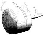
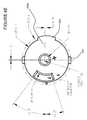
- FIG. 1illustrates an embodiment of the invention alone in perspective view and as mounted in a shaft of a handle-based piece of equipment as shown in cutaway view.
- FIG. 2illustrates an embodiment of the invention broken into an exploded view of the main components along with the shaft handle and blow up views of the major components in transparent shading.
- FIG. 3Aillustrates a detailed cutaway view of the main components of an embodiment of the invention.
- FIG. 3Billustrates a detailed cutaway view showing the negative battery contact, also shown in full in exploded view in FIG. 4 .
- FIG. 3Cillustrates a detailed cutaway view showing the positive battery contact, also shown in full in exploded view in FIG. 4 .
- FIG. 4illustrates an exploded view “A” of the main mount components along with the positive battery contact and battery, while view “B 1 ” shows a top oriented view of the insulator, negative battery contact, electronics package, here a printed circuit board or PCB and cap, while view “B 2 ” shows a bottom oriented view of the same components shown in view “B 1 ”.
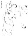
- FIG. 4Aillustrates an exploded view “A” of the main mount components of a second embodiment of the invention along with the positive and negative battery contact and battery, while view “B” shows a bottom oriented view of the insulator, positive and negative battery contact, electronics package, here a printed circuit board or PCB and cap.
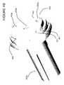
- FIG. 4Billustrates a perspective view of the shaft enclosure and insulator of a second embodiment of the invention along with the positive and negative battery contact and battery.
- FIG. 4Cillustrates a perspective view of the insulator along with the positive and negative battery contact and battery.
- FIG. 4Dillustrates a perspective close-up view of the positive battery contact.
- FIG. 4Eillustrates a top view of an embodiment of the insulator that is configured to house a battery along with specific exemplary dimensions.
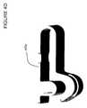
- FIG. 4Fillustrates a first side of the embodiment of the insulator of FIG. 4E .
- FIG. 4Gillustrates a second side of the embodiment of the insulator of FIG. 4E .
- FIG. 4Hillustrates a cross section view “A” of FIG. 4F .
- FIG. 4Iillustrates a bottom view of the embodiment of the insulator of FIG. 4E .
- FIG. 5illustrates a close up perspective view of the PCB and associated positive and negative contacts that are configured to make an electrical connection with the positive battery contact and the negative battery contact respectively.
- FIG. 5Aillustrates a second embodiment of the positive battery contact located in the shaft enclosure.
- FIG. 6illustrates a close up perspective view of the cap with PCB and negative battery contact showing along with a coupling element, here four coupling points, and alignment element.
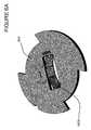
- FIG. 6Aillustrates a second embodiment of the negative batter contact having faceted surfaces as shown from the bottom side of the insulator.
- FIG. 6Billustrates the embodiment of FIG. 6A as shown from the top side of the insulator.
- FIG. 7illustrates a close up perspective view of the cap and alignment element.
- FIG. 8illustrates a cutaway view of a second embodiment of the electronics package in longitudinal form along with a second embodiment of a coupling element.
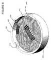
- FIG. 9illustrates an embodiment of a wireless antenna, for example a BLUETOOTH® antenna, configured to mount within the cap.
- a wireless antennafor example a BLUETOOTH® antenna
- FIG. 9Aillustrates an embodiment of the cap having two antennas, a wireless antenna, for example a BLUETOOTH® antenna and a GPS antenna.
- a wireless antennafor example a BLUETOOTH® antenna and a GPS antenna.
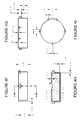
- FIG. 10shows an embodiment of the shaft enclosure having an angled area.
- the shaft enclosurecouples with cap as is shown in the right portion of the figure.
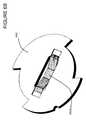
- FIG. 11shows an embodiment of the grip, for example having a hole in the top of the grip that allows for the grip to be rolled down the shaft as is shown and enabling access to the cap without removing the grip from the shaft.
- FIG. 12shows the grip rolled back over the angled area and onto the side portions of the cap. This enables the end of the cap to be seen through the hole in the end of the grip, and enables the grip to provide extra support for the motion capture element.
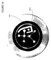
- FIG. 13illustrates a spear collet cutaway view of an embodiment of the invention.
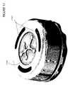
- FIG. 14illustrates a rear perspective view of the embodiment shown in FIG. 13 .
- FIG. 15illustrates a handle-based embodiment of the invention.
- FIG. 16illustrates a structural view of another handle-based embodiment of the invention.
- FIG. 17illustrates another handle-based embodiment of the invention.
- FIG. 18illustrates the handle-based embodiment of the invention of FIG. 17 showing the location of the antenna on the outer portion of the enclosure.
- FIG. 19illustrates the embodiment of FIG. 17 with the antenna shown in FIG. 18 covered with non-conductive material.
- FIG. 20illustrates a cutaway view of an embodiment of the invention coupled with a piece of equipment having a handle.
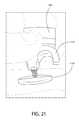
- FIG. 21illustrates an embodiment of the invention configured to couple with a helmet.
- FIG. 22illustrates the embodiment shown in FIG. 21 coupled with the helmet.
- FIG. 23illustrates a close-up of the embodiment shown in FIG. 22 .
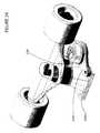
- FIG. 24illustrates a perspective view of an embodiment of the invention coupled with a skateboard truck.
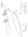
- FIG. 25illustrates an embodiment coupled with planar equipment.
- the apparatusmay be located internal or external to the piece of sporting equipment and may show a visual marker for use in visually obtaining motion in combination with electronically detected motion obtained with the motion capture sensor.
- the outer portion of the enclosuremay display a visual marker on the outer portion while the inner portion of the enclosure may be located on or within a shaft or grip in the handle portion of the equipment for example.
- FIG. 1illustrates an embodiment of the invention 100 alone in perspective view and as mounted in a shaft of a piece of movement equipment, for example a baseball bat, hockey stick, lacrosse stick, golf club, tennis racquet or any piece of equipment having a handle near shaft 110 as shown in cutaway view.
- a mount for a new piece of equipment or that can be retrofitted in an existing piece of equipmentmay be located in the handle portion of the shaft, or for example within a grip that is to be attached to the shaft, and is configured to hold electronics and/or a visual marker.
- FIG. 2illustrates an embodiment of the invention broken into an exploded view of the main components along with the shaft handle and blow up views of the major components in transparent shading.
- One or more embodiments of the mountinclude enclosure or shaft enclosure 220 and expander 210 that may be coupled with an attachment mechanism, for example a screw aligned along an axis parallel to the axis of the shaft.
- the shaft enclosure and expanderare situated within the handle, i.e., shaft 110 .
- the screwis then rotated to move the shaft enclosure towards the expander, which thus forces legs of the shaft enclosure in a direction orthogonal to the axis of the shaft.
- the force of the shaft enclosure against the inner wall of the shaftthus couples the shaft enclosure to the shaft based on the coefficient of static friction therebetween.
- any other mechanism of coupling the shaft enclosure to a shaft in a non-permanent manneris in keeping with the spirit of the invention.
- either the electronics package or a weight element that may for example weigh the same as the electronicsis coupled with the shaft enclosure.
- Cap 230is coupled with the shaft enclosure in either case, which provides a cover for the weight element or electronics package and which may include a visual marker and/or logo on the cap.
- One or more embodiments of the electronics packageare removable to comply with any sporting rules that do not allow instrumented sporting equipment for example. Any other method or structure that enables a non-permanent mount of the apparatus that requires no modification of the shaft is in keeping with the spirit of the invention.
- an identification element or ID stickerfor example an RFID tag may be mounted within the enclosure, cap, or any other portion of the apparatus, for equipment identification, or shot count functionality.
- the identification elementmay also be implemented integral to, or coupled with the PCB in any manner as desired.
- a positive battery contact, printed circuit board or PCB, an insulator or insulative spacer, with negative electrical contact and batterymay be installed between the shaft enclosure and cap.
- a wireless antenna and/or GPS antennamay be coupled with the cap or alternatively may be implemented integral to the PCB as desired. Also see FIGS. 3A-C , 4 , 4 A-D and 9 for more detailed views.
- FIG. 3Aillustrates a detailed cutaway view of the main components of an embodiment of the invention, specifically expander 210 , shaft enclosure 220 and cap 230 .
- FIG. 3Billustrates a detailed cutaway view showing negative battery contact 450 , also shown in full in exploded view in FIG. 4 .
- FIG. 3Cillustrates a detailed cutaway view showing positive battery contact 420 , also shown in full in exploded view in FIG. 4 .
- Optional O-ring indentation 310 on shaft enclosure 220provides a potential well for O-ring 320 to be located. Different size O-rings may be utilized to provide a secure fit on the end of shaft enclosure 220 on the end near cap 230 .
- FIG. 4illustrates an exploded view “A” of the main mount components, namely expander 210 , shaft enclosure 220 along with screw 410 , positive battery contact 420 and battery 430 , while view “B 1 ” shows a top oriented view of the insulator 440 , negative battery contact 450 , electronics package 460 , here a printed circuit board or PCB and cap 230 , while view “B 2 ” shows a bottom oriented view of the same components shown in view “B 1 ”.
- the left portion of shaft enclosure 220shows extensions or “legs” that allow for the shaft enclosure to radially expand when expander 210 is pulled along the axis shown by screw 410 , when screw 410 is rotated.
- expander 210may include a protrusion (shown on the left side of the expander) that aligns in a slot formed by two of the shaft enclosure's legs. In this manner, expander 210 is pulled along the axis of the screw without rotating along that axis.
- Electronics package 460for example may include active motion capture electronics that are battery powered, passive or active shot count components, for example a passive or active RFID tag, which for example may be coupled with electronics package 460 or for example coupled with insulator 440 .
- a GPS antennamay also be coupled with electronics package 460 or cap 230 (see FIG. 9A ).
- Embodiments of the electronicsmay include motion capture accelerometers and/or gyroscopes and/or an inertial measurement unit along with wireless transmitter/receiver or transceiver components.
- the RFID tagenables golf shots for each club associated with a golfer to be counted.
- the RFID tagmay be coupled with any component shown as RFID tags are tiny, for example cap 230 or shaft enclosure 220 or electronics package 460 , or any other element. Golf shots may optionally be counted via an identifier associated with motion capture electronics on the golf club in conjunction with a mobile computer, for example an IPHONE® equipped with an RFID reader that concentrates the processing for golf shot counting on the mobile computer instead of on each golf club.
- the visual markermay be mounted on cap 230 , shown as a circle with dots in view B 1 may be utilized with visual motion capture cameras.
- An equipment numberfor example a golf club number may also be displayed on in a display area of the cap to indicate which club number is associated with the golf club, which is shown as a small circle with a number in it in view B 1 .
- Embodiments of the visual markermay be passive or active, meaning that they may either have a visual portion that is visually trackable or may include a light emitting element such as a light emitting diode (LED) that allows for image tracking in low light conditions respectively. This for example may be implemented with a graphical symbol or colored marker at the cap of the mount on the shaft at the end of the handle for example.
- Motion analysismay be performed externally, for example using a camera and computer system based on the visual marker in any captured images.
- the visual datamay also be utilized in motion analysis in combination with any wireless data from electronics package 460 .
- FIG. 4Aillustrates an exploded view “A” of the main mount components of a second embodiment of the invention, namely expander 210 a , with ribs slightly offset with respect to expander 210 of FIG. 4 .
- FIG. 4Aalso shows a second embodiment of shaft enclosure 220 a having coupling elements that enable second embodiment of insulator 440 a to securely couple to shaft enclosure 220 a without falling out if the mount is turned upside down for example.
- insulator 440 aholds battery 430 inside while providing access to the battery so that positive battery contact 420 a and negative battery contact 450 a can make electrical contact with battery 430 .
- Weight element 490can be any shape so long as weight element 490 fits within, or couples in any direct or indirect manner with shaft enclosure 220 or 220 a and cap 230 for example. Weight element 490 can be made to weigh as near as desired to the weight of the components that it replaces, for example to comply with any sporting rules that do not allow instrumented sporting equipment, e.g., during competition. Weight element 490 can also be utilized with the embodiment shown in FIG. 4 as one skilled in the art will appreciate.
- FIG. 4Billustrates a perspective view of shaft enclosure 220 a and insulator 440 a of the second embodiment of the invention of FIG. 4A along with the positive and negative battery contact 420 a and 450 a respectively (situated above holes in insulator 440 a ) along with battery 430 that is internally held within insulator 440 a .
- Insulator 440 aincludes for example snap components, e.g., coupling elements 441 that couple with coupling elements 221 of shaft enclosure 220 a so that insulator 440 a and hence battery 430 do not fall out when the cap is removed.
- tab 442may be engaged with for example a finger, screw driver or other implement to disengage coupling elements 441 from coupling elements 221 .
- Alignment component 443enables rotational alignment of the insulator with the shaft enclosure.
- FIG. 4Cillustrates a perspective view of the insulator along with the positive and negative battery contact 420 a and 450 a respectively, and battery 430 .
- Coupling elements 441are shown on the top and bottom in the written page, however any type of coupling element may be utilized in keeping with the spirit of the invention as desired.
- FIG. 4Dillustrates a perspective close-up view of positive battery contact 420 a .
- the positive and negative battery contactsmay utilize the same structure. Any type of positive and negative battery contacts may be utilized so long as they maintain electric connection between the battery and electronics package.
- FIG. 4Eillustrates a top view of an embodiment of insulator 440 a that is configured to house a battery along with specific exemplary dimensions.
- tab 442may be engaged with for example a finger, screw driver or other implement to disengage coupling elements 441 from the coupling elements shown for example in FIG. 4B .
- the numbersrepresent millimeters, and angle tolerances are within 2 degrees.
- this embodiment of insulator 440 ais configured to house a 6.4 mm battery.
- insulator 440 amay be constructed to be compliant with EU Directive 2002/95/EC (RoHS) and EU Directive 2002/96/EC (WEEE). Embodiments may alternatively be constructed to be compliant with any other electrical or manufacturing standards as desired.
- FIG. 4Fillustrates a first side of the embodiment of the insulator of FIG. 4E . See also FIG. 4H for the cross section view.
- FIG. 4Gillustrates a second side of the embodiment of the insulator of FIG. 4E .
- FIG. 4Hillustrates a cross section view “A” of FIG. 4F .
- FIG. 4Iillustrates a bottom view of the embodiment of the insulator of FIG. 4E .
- FIG. 5illustrates a close up perspective view of the electronics package 460 or PCB and associated positive contact 510 and negative contact 520 that are configured to make an electrical connection with the positive battery contact 420 and the negative battery contact 450 respectively. See also FIG. 4 for an exploded view of the relative positioning of the components shown in this figure.
- FIG. 5Aillustrates a second embodiment of positive battery contact 420 b located in the shaft enclosure.
- This embodimentis symmetrical in that there are two opposing sets of upward projections from the base plane that contacts shaft enclosure 220 .
- One of the opposing sets of upward projections of positive battery contact 420 bare slightly wider and are positioned within areas on shaft enclosure 220 to allow for radially aligning positive battery contact 420 b with respect to shaft enclosure 220 .
- FIG. 6illustrates a close up perspective view of cap 230 with electronics package 460 or PCB and negative battery contact 450 coupled with insulator 440 showing along with a coupling element, here four coupling points 610 (with only the top two shown with reference number 610 with the inside portions visible, while the opposing two have only the initial slot openings in the cap visible), and alignment element 620 .
- a coupling elementhere four coupling points 610 (with only the top two shown with reference number 610 with the inside portions visible, while the opposing two have only the initial slot openings in the cap visible), and alignment element 620 .
- FIG. 6Aillustrates a second embodiment of the negative battery contact 450 b having faceted surfaces as shown from the bottom side of insulator 440 .
- FIG. 6Billustrates the embodiment of FIG. 6A as shown from the top side of the insulator.
- the right portion of negative battery contact 450 b as shownmay be folded over to engage insulator 440 while the opposing end of negative battery contact 450 b may freely travel in a slot provided in insulator 440 .
- the slotallows for the negative battery contact 450 b to flatten, and hence travel in the slot, based on the force generated by placing the battery against negative battery contact 450 b.
- FIG. 7illustrates a close up perspective view of the cap and alignment element.
- Alignment element 620allows for the angular alignment of insulator 440 , and electronics package 460 that have indents on their sides to engage the alignment element 620 . (See FIG. 4 ).
- positive battery contact 420 and negative electrical contact 450are also aligned rotationally since they couple to respective components non-rotationally, for example.
- FIG. 8illustrates a cutaway view of a second embodiment of electronics package 460 a in longitudinal form along with a second embodiment of a coupling element.
- Any other orientation of electronicsis in keeping with the spirit of the invention so long as the mount is configured to hold the desired electronics package.
- Embodiments of the inventiondo not require modifying the piece of equipment, for example to include threads within the shaft.
- Embodiments of the inventionalso can be flush mounted with the normal end of a shaft or have any desired low profile extension from a non-instrumented club.
- Embodiments of the inventiongenerally utilize a mount that is separate from the electronics so that the electronics package can be easily removed and replaced, or so that the battery can be easily removed and replaced, for example without any tools.
- a different coupling mechanismis used versus coupling points 610 , namely threads 810 that engage shaft enclosure 220 , which in this embodiment has corresponding threads.
- FIG. 9illustrates an embodiment of wireless antenna 910 , configured to mount within cap 230 as shown in the right portion of the figure.
- the wireless antennamay be coupled with the electronics package 460 or may include any conductive element in any shape that can radiate electromagnetic energy.
- FIG. 9Aillustrates an embodiment of the cap having two antennas, a wireless antenna, for example a BLUETOOTH® antenna and a GPS antenna 920 .
- the GPS antennais optional and may be mounted in cap 230 as wireless antenna 910 is, or may be implemented in a different form factor or coupled with the PCB in any direct or indirect manner as one skilled in the art will appreciate. See also FIG. 18 for another embodiment of the antenna configuration.
- FIG. 10shows an embodiment of shaft enclosure 220 b with angled area 1001 .
- Shaft enclosure 220 bcouples with cap 230 as is shown in the right portion of the figure.
- Any other embodiment of the shaft enclosure detailed hereinmay be utilized on a shaft having a grip that either includes a hole or that does not include a hole and that wraps partially or fully around the motion capture element.
- FIG. 11shows grip 1101 , having a hole in the top of the grip that allows for the grip to be rolled down the shaft as is shown at area 1101 a . This enables cap 230 to be exposed, removed or otherwise accessed without removing the grip from the piece of equipment for example.
- FIG. 12shows grip at area 1101 b rolled back over angled area 1001 and onto the side portions of cap 230 . This enables the end of the cap 230 to be seen through the hole in the end of the grip, and enables the grip to provide extra support for the motion capture element.
- FIG. 13illustrates a spear collet cutaway view of an embodiment of the invention.
- Spear 1301couples enclosure 220 with the hole 1302 in the handle-based piece of equipment.
- the spearhas a narrower portion shown at the hole, but this is not required so long as the spear is capable of holding enclosure 220 to the handle.
- FIG. 14illustrates a rear perspective view of the embodiment shown in FIG. 13 .
- visual marker 1401 for motion capture detection via visual methodsis shown on cap 230 of enclosure 220 .
- FIG. 15illustrates a handle-based embodiment of the invention.
- visual marker 1401is visible and in one or more embodiment may contain high contrast or active elements to enable easier visual detection of the orientation and/or motion of the motion capture sensor for example with a camera.
- the embodiment shownmay be coupled with a baseball bat or other handle based piece of equipment for example.
- FIG. 16illustrates a structural view of another handle-based embodiment of the invention.
- cap 230which covers the enclosure, is isolated from the piece of equipment via shock puck 1601 .
- Shock puck 1601may include any material that dampens or otherwise limits G-forces from the piece of equipment to assert force on the motion capture sensor.
- FIG. 17illustrates another handle-based embodiment of the invention.
- uncovered portion 1701may be utilized to house an antenna external to the inside portion of the enclosure.
- areas 1702may be made from any material that enables radio frequency waves to emanate from the internal volume of the enclosure.
- the uncovered portionmay provide an area for a small antenna that is then covered for protection as is shown in the next figure.
- FIG. 18illustrates the handle-based embodiment of the invention of FIG. 17 showing the location of the antenna on the outer portion of the enclosure.
- antenna 1801may be placed in the uncovered portion 1701 as shown in FIG. 17 , which is shown in this figure partially filled with epoxy.
- Two holesmay be drilled through the cap to provide feed lines for antenna 1801 and also for ground point 1802 .
- the antenna and ground pointmay be covered as is shown in the next figure.
- Embodiments of the enclosurethat are metallic and for example behave as an electromagnetic shield may utilize this type of antenna and provide for an extremely durable enclosure and exceptional antenna coverage for example.
- FIG. 19illustrates the embodiment of FIG. 17 with the antenna shown in FIG. 18 covered with non-conductive material. As shown, the uncovered portion shown in FIG. 17 is covered at 1901 for example, and flush with the other portions of the cap to provide a finished cap for the enclosure that provides maximal antenna covered, while still providing a visual marker for bot electronic and visual motion capture sensing capabilities.
- FIG. 20illustrates a cutaway view of an embodiment of the invention coupled with a piece of equipment having a handle.
- shock puck 1601surrounds enclosure 220 to provide high G-force shock protection to the internal components of the motion capture sensor.
- One or more embodiments of the inventionmay be covered with an outer protective area 2001 , which may be transparent in one or more embodiments.
- FIG. 21illustrates an embodiment of the invention configured to couple with a helmet.
- enclosure 220couples with mount 2101 that includes a half circle opening for example that may be fit around a helmet facemask tube or grill.
- Screw 2102may be tightened to close the gap between the mount and the screw backing to couple enclosure 220 to a helmet.
- FIG. 22illustrates the embodiment shown in FIG. 21 coupled with the helmet.
- enclosure 220is coupled with helmet via facemask tube or grill 2201 as per the elements shown in FIG. 21 .
- Any other method of coupling the enclosure with a helmetis in keeping with the spirit of the invention.
- FIG. 23illustrates a close-up of the embodiment shown in FIG. 22 .
- Visual marker 1401is shown on the outside portion of the helmet for use in capturing motion with an external camera for example.
- FIG. 24illustrates a perspective view of an embodiment of the invention coupled with a skateboard truck.
- enclosure 220couples with or otherwise includes mount 2401 that is configured to couple with the existing screws of a skateboard truck mount 2402 .
- mount 2401that is configured to couple with the existing screws of a skateboard truck mount 2402 .
- mount 2401that is configured to couple with the existing screws of a skateboard truck mount 2402 .
- the same configurationmay be reshaped to fit holes associated with a snowboard binding or other planar oriented piece of equipment including skis as is shown in the next figure.
- FIG. 25illustrates an embodiment coupled with planar equipment.
- enclosure 220may be mounted along with the snowboard binding 2501 of a snowboard.
- the enclosuremay be coupled with the snowboard mount itself, or utilize a flat version of mount 2401 to couple with an existing screw used to mount the binding.
- enclosure 220may mount on or near the top of the surfboard or on the underside of the surfboard near the skeg 2502 since surfboards may be made from materials that enable the transmission of electromagnetic waves.
- enclosure 220may be housed in streamlined mount 2503 and adhesively mounted to any planar equipment, for example the snowboard, surfboard or skis. Streamlined mounts provide low wind or water drag and minimize interference with external objects for example.
Landscapes
- Health & Medical Sciences (AREA)
- General Health & Medical Sciences (AREA)
- Physical Education & Sports Medicine (AREA)
- Engineering & Computer Science (AREA)
- Microelectronics & Electronic Packaging (AREA)
- Physics & Mathematics (AREA)
- Electromagnetism (AREA)
- Battery Mounting, Suspending (AREA)
Abstract
Description
- Existing mounts for sporting equipment electronics require alteration of an existing piece of sporting equipment before attaching the mount and hence electronics. For example, known mounts require modification of the shaft of the piece of equipment to include threads.
- Some mounts extend longitudinally away from the normal ending point of the shaft for a distance that is far enough to interfere with or provide a confusing point at which to grasp the club.
- Other mounts combine the electronics on the mount itself in a monolithic package that does not allow for the weight of the club to remain constant with or without electronics installed. For example, in sports with rules against instrumented sporting equipment, the weight of an instrumented piece of sporting equipment differs from the weight of the same non-instrumented piece of sporting equipment that complies with competition rules.
- There are no known systems that include electronics within the shaft of a piece of sporting equipment that are also utilized to provide a visual marker for motion capture. Traditionally, mounts have been used for electronics or visual markers, but not both.
Claims (20)
Priority Applications (5)
| Application Number | Priority Date | Filing Date | Title |
|---|---|---|---|
| US13/688,213US9622361B2 (en) | 2010-08-26 | 2012-11-29 | Enclosure and mount for motion capture element |
| PCT/US2013/072461WO2014085744A1 (en) | 2012-11-29 | 2013-11-29 | Enclosure and mount for motion capture element |
| US15/011,100US9746354B2 (en) | 2010-08-26 | 2016-01-29 | Elastomer encased motion sensor package |
| US15/017,850US9643049B2 (en) | 2010-08-26 | 2016-02-08 | Shatter proof enclosure and mount for a motion capture element |
| US15/585,609US10254139B2 (en) | 2010-08-26 | 2017-05-03 | Method of coupling a motion sensor to a piece of equipment |
Applications Claiming Priority (6)
| Application Number | Priority Date | Filing Date | Title |
|---|---|---|---|
| US12/868,882US8994826B2 (en) | 2010-08-26 | 2010-08-26 | Portable wireless mobile device motion capture and analysis system and method |
| US12/901,806US9320957B2 (en) | 2010-08-26 | 2010-10-11 | Wireless and visual hybrid motion capture system |
| US13/048,850US8465376B2 (en) | 2010-08-26 | 2011-03-15 | Wireless golf club shot count system |
| US13/191,309US9033810B2 (en) | 2010-08-26 | 2011-07-26 | Motion capture element mount |
| US13/306,869US9028337B2 (en) | 2010-08-26 | 2011-11-29 | Motion capture element mount |
| US13/688,213US9622361B2 (en) | 2010-08-26 | 2012-11-29 | Enclosure and mount for motion capture element |
Related Parent Applications (1)
| Application Number | Title | Priority Date | Filing Date |
|---|---|---|---|
| US13/306,869Continuation-In-PartUS9028337B2 (en) | 2010-08-26 | 2011-11-29 | Motion capture element mount |
Related Child Applications (2)
| Application Number | Title | Priority Date | Filing Date |
|---|---|---|---|
| US15/011,100Continuation-In-PartUS9746354B2 (en) | 2010-08-26 | 2016-01-29 | Elastomer encased motion sensor package |
| US15/017,850Continuation-In-PartUS9643049B2 (en) | 2010-08-26 | 2016-02-08 | Shatter proof enclosure and mount for a motion capture element |
Publications (2)
| Publication Number | Publication Date |
|---|---|
| US20130095941A1 US20130095941A1 (en) | 2013-04-18 |
| US9622361B2true US9622361B2 (en) | 2017-04-11 |
Family
ID=48086356
Family Applications (1)
| Application Number | Title | Priority Date | Filing Date |
|---|---|---|---|
| US13/688,213Active2030-12-18US9622361B2 (en) | 2010-08-26 | 2012-11-29 | Enclosure and mount for motion capture element |
Country Status (1)
| Country | Link |
|---|---|
| US (1) | US9622361B2 (en) |
Cited By (7)
| Publication number | Priority date | Publication date | Assignee | Title |
|---|---|---|---|---|
| US10099101B1 (en) | 2017-12-07 | 2018-10-16 | Ssg International, Llc | Golf club grip with sensor housing |
| USD849166S1 (en) | 2017-12-07 | 2019-05-21 | Ssg International, Llc | Golf putter grip |
| US10565888B2 (en) | 2013-02-17 | 2020-02-18 | Ronald Charles Krosky | Instruction production |
| US20220309883A1 (en)* | 2021-03-29 | 2022-09-29 | West Flagler Associates, Ltd. | Multi-sport challenge systems and methods |
| US20230377427A1 (en)* | 2021-03-29 | 2023-11-23 | West Flagler Associates, Ltd. | Multi-sport challenge systems and methods |
| US12112603B2 (en) | 2021-03-29 | 2024-10-08 | West Flagler Associates, LTD | Multi-sport challenge systems and methods |
| US12194340B2 (en) | 2022-02-03 | 2025-01-14 | Tourbuilt, Llc | Systems and methods for measuring and analyzing the motion of a swing and matching the motion of a swing to optimized swing equipment |
Families Citing this family (47)
| Publication number | Priority date | Publication date | Assignee | Title |
|---|---|---|---|---|
| US9619891B2 (en) | 2010-08-26 | 2017-04-11 | Blast Motion Inc. | Event analysis and tagging system |
| US9604142B2 (en) | 2010-08-26 | 2017-03-28 | Blast Motion Inc. | Portable wireless mobile device motion capture data mining system and method |
| US9626554B2 (en) | 2010-08-26 | 2017-04-18 | Blast Motion Inc. | Motion capture system that combines sensors with different measurement ranges |
| US9396385B2 (en) | 2010-08-26 | 2016-07-19 | Blast Motion Inc. | Integrated sensor and video motion analysis method |
| US9607652B2 (en) | 2010-08-26 | 2017-03-28 | Blast Motion Inc. | Multi-sensor event detection and tagging system |
| US9646209B2 (en) | 2010-08-26 | 2017-05-09 | Blast Motion Inc. | Sensor and media event detection and tagging system |
| US9247212B2 (en) | 2010-08-26 | 2016-01-26 | Blast Motion Inc. | Intelligent motion capture element |
| US9940508B2 (en) | 2010-08-26 | 2018-04-10 | Blast Motion Inc. | Event detection, confirmation and publication system that integrates sensor data and social media |
| US9261526B2 (en) | 2010-08-26 | 2016-02-16 | Blast Motion Inc. | Fitting system for sporting equipment |
| US20150237460A1 (en)* | 2011-06-10 | 2015-08-20 | Aliphcom | Wireless enabled cap for data-capable band |
| US9258670B2 (en)* | 2011-06-10 | 2016-02-09 | Aliphcom | Wireless enabled cap for a data-capable device |
| US8894502B2 (en)* | 2011-09-14 | 2014-11-25 | Skyhawke Technologies, Llc | Apparatus for housing telemetry, sensing, processing and other electronic components and affixing such apparatus to a golf club |
| US8517850B1 (en) | 2012-12-11 | 2013-08-27 | Cobra Golf Incorporated | Golf club grip with device housing |
| US9114294B2 (en) | 2012-02-28 | 2015-08-25 | Cobra Golf Incorporated | Distance gapping golf club set with dual-range club |
| WO2014092213A1 (en)* | 2012-12-11 | 2014-06-19 | Du-Sung Technology Co.,Ltd. | System and operating method for real-time analysis of golf swing motion on golf club |
| US9731179B2 (en)* | 2013-01-24 | 2017-08-15 | Wilson Sporting Goods Co. | Bat customization system |
| US10387930B2 (en) | 2013-01-24 | 2019-08-20 | Wilson Sporting Goods Co. | Bat customization system |
| US9308424B2 (en)* | 2013-01-24 | 2016-04-12 | Wilson Sporting Goods Co. | Bat customization system |
| US9956464B2 (en) | 2013-01-24 | 2018-05-01 | Wilson Sporting Goods Co. | Ball bat barrel with luminescent interior |
| US9511267B2 (en)* | 2013-01-24 | 2016-12-06 | Wilson Sporting Goods Co. | Bat customization system |
| US20140274439A1 (en) | 2013-03-15 | 2014-09-18 | Sanwood Llc | Impact Indication and Data Tracking Devices and Methods |
| US20150202510A1 (en)* | 2013-12-24 | 2015-07-23 | Snypr, Inc. | System for training sport mechanics |
| EP3131426B1 (en) | 2014-04-14 | 2019-12-11 | Flyclip LLC | Lace adjuster assembly including feedback assembly for use in visualizing and measuring athletic performance |
| US12414599B2 (en) | 2014-04-14 | 2025-09-16 | Laceclip Llc | Lace adjuster assembly including feedback assembly for use in visualizing and measuring athletic performance |
| US11937666B2 (en) | 2014-04-14 | 2024-03-26 | Laceclip Llc | Lace adjuster |
| USD854640S1 (en)* | 2014-04-15 | 2019-07-23 | Edward Rogacki | Weighted golf club grip |
| US10520557B2 (en)* | 2014-04-24 | 2019-12-31 | Arthrokinetic Institute, Llc | Systems, devices, and methods for recording and transmitting data |
| KR102233301B1 (en)* | 2014-06-12 | 2021-03-31 | 순위안 카이화 (베이징) 테크놀로지 컴퍼니 리미티드 | Removable motion sensor embedded in a sport instrument |
| US9744403B2 (en)* | 2014-06-13 | 2017-08-29 | Jorge H. Rangel | Activity tracking racquet attachment device |
| GB2528838A (en)* | 2014-07-21 | 2016-02-10 | Christopher John Clegg | A golf training system |
| JP2016093236A (en)* | 2014-11-12 | 2016-05-26 | セイコーエプソン株式会社 | Motion detector, retainer, and moving body with sensor |
| US10124230B2 (en) | 2016-07-19 | 2018-11-13 | Blast Motion Inc. | Swing analysis method using a sweet spot trajectory |
| US9694267B1 (en) | 2016-07-19 | 2017-07-04 | Blast Motion Inc. | Swing analysis method using a swing plane reference frame |
| US10974121B2 (en) | 2015-07-16 | 2021-04-13 | Blast Motion Inc. | Swing quality measurement system |
| CA3031040C (en) | 2015-07-16 | 2021-02-16 | Blast Motion Inc. | Multi-sensor event correlation system |
| US11565163B2 (en) | 2015-07-16 | 2023-01-31 | Blast Motion Inc. | Equipment fitting system that compares swing metrics |
| US11577142B2 (en) | 2015-07-16 | 2023-02-14 | Blast Motion Inc. | Swing analysis system that calculates a rotational profile |
| US9616307B1 (en)* | 2015-10-21 | 2017-04-11 | Kai-Ping Chiang | Adjustable-counterbalanced handle |
| WO2017095936A1 (en)* | 2015-12-01 | 2017-06-08 | Proxr, Llc | Baseball bat knob cavity to house sensor |
| US11452585B2 (en)* | 2016-03-01 | 2022-09-27 | Ignident Gmbh | Device and method for measuring a movement of a mandible |
| US10265602B2 (en) | 2016-03-03 | 2019-04-23 | Blast Motion Inc. | Aiming feedback system with inertial sensors |
| US10130305B2 (en) | 2016-04-22 | 2018-11-20 | Under Armour, Inc. | Device and methods for automated testing |
| CN108064404B (en)* | 2016-12-30 | 2020-06-23 | 深圳市柔宇科技有限公司 | Supporting assembly and display device |
| US10786728B2 (en) | 2017-05-23 | 2020-09-29 | Blast Motion Inc. | Motion mirroring system that incorporates virtual environment constraints |
| US11540774B2 (en)* | 2018-12-18 | 2023-01-03 | Movano Inc. | Removable smartphone case for radio wave based health monitoring |
| USD946100S1 (en)* | 2020-08-11 | 2022-03-15 | Eaton Intelligent Power Limited | End cap for golf club grip |
| USD1029972S1 (en)* | 2021-06-20 | 2024-06-04 | Phinetworks Co., Ltd. | Sensor terminal for detecting golfer swing motion |
Citations (207)
| Publication number | Priority date | Publication date | Assignee | Title |
|---|---|---|---|---|
| US1712537A (en) | 1924-12-01 | 1929-05-14 | Walter P White | Speed-indicating device for golf clubs |
| US2038840A (en) | 1935-06-03 | 1936-04-28 | Eric E Hall | Tool for affixing elastic tubular handgrips to the shafts of golf clubs |
| US2218268A (en) | 1936-08-13 | 1940-10-15 | Reid Glenn Percival | Golf club |
| US3182508A (en) | 1962-05-22 | 1965-05-11 | Nat Castings Co | Golf drive metering apparatus |
| US3223555A (en) | 1962-04-05 | 1965-12-14 | Yardney International Corp | Sealed battery stacked electrode assembly |
| US3226704A (en) | 1963-07-22 | 1965-12-28 | Petrash Edward | Golf club accelerometer |
| US3270564A (en) | 1964-05-18 | 1966-09-06 | James W Evans | Athletic swing measurement system |
| US3606327A (en) | 1969-01-28 | 1971-09-20 | Joseph M Gorman | Golf club weight control capsule |
| US3788647A (en) | 1971-12-06 | 1974-01-29 | Athletic Swing Measurement | Swing measurement system |
| US3792863A (en) | 1972-05-30 | 1974-02-19 | Athletic Swing Measurement | Swing measurement system and method employing simultaneous multi-swing display |
| US3806131A (en) | 1972-03-29 | 1974-04-23 | Athletic Swing Measurement | Swing measurement and display system for athletic implements |
| US3945646A (en) | 1974-12-23 | 1976-03-23 | Athletic Swing Measurement, Inc. | Athletic swing measurement system and method |
| US4088324A (en) | 1976-12-06 | 1978-05-09 | Farmer Everett Walter | Athletic implement with visual range display |
| USD295207S (en) | 1985-07-25 | 1988-04-12 | Spalding & Evenflo Companies, Inc. | Golf club grip |
| US4759219A (en) | 1987-05-15 | 1988-07-26 | Swingspeed, Inc. | Swing parameter measurement system |
| US4898389A (en) | 1987-09-08 | 1990-02-06 | Plutt Daniel J | Impact indicating golf training device |
| US4910677A (en) | 1988-05-18 | 1990-03-20 | Joseph W. Remedio | Golf score recording system and network |
| US4912836A (en) | 1987-01-30 | 1990-04-03 | Avetoom Garnic C | Method of installing a sports equipment grip |
| US4940236A (en) | 1985-07-26 | 1990-07-10 | Allen Dillis V | Computer golf club |
| US4991850A (en) | 1988-02-01 | 1991-02-12 | Helm Instrument Co., Inc. | Golf swing evaluation system |
| US5056783A (en) | 1989-10-18 | 1991-10-15 | Batronics, Inc. | Sports implement swing analyzer |
| US5086390A (en) | 1990-01-16 | 1992-02-04 | Matthews Gordon H | System for monitoring play of a golfer |
| US5111410A (en) | 1989-06-23 | 1992-05-05 | Kabushiki Kaisha Oh-Yoh Keisoku Kenkyusho | Motion analyzing/advising system |
| US5127044A (en) | 1990-02-20 | 1992-06-30 | Golf Scoring Systems Unlimited, Inc. | Automatic golf scoring and scheduling system |
| US5184295A (en) | 1986-05-30 | 1993-02-02 | Mann Ralph V | System and method for teaching physical skills |
| US5230512A (en) | 1992-05-08 | 1993-07-27 | Tattershall H David | Golf training device |
| US5233544A (en) | 1989-10-11 | 1993-08-03 | Maruman Golf Kabushiki Kaisha | Swing analyzing device |
| US5249967A (en) | 1991-07-12 | 1993-10-05 | George P. O'Leary | Sports technique video training device |
| US5259620A (en)* | 1990-12-14 | 1993-11-09 | Joseph Marocco | Gold club training device |
| US5283733A (en) | 1992-03-24 | 1994-02-01 | Colley Russell H | Computer on-line golf scoring device |
| US5298904A (en) | 1992-08-04 | 1994-03-29 | Olich Kirk J | Distance measuring system |
| US5332225A (en) | 1992-04-22 | 1994-07-26 | Mitsuo Ura | Equipment for ball hitting practice |
| US5333061A (en) | 1992-03-19 | 1994-07-26 | Midori Katayama | Method and apparatus for producing an instructional video analyzing a golf swing |
| US5364093A (en) | 1991-12-10 | 1994-11-15 | Huston Charles D | Golf distance measuring system and method |
| WO1994027683A1 (en) | 1993-06-02 | 1994-12-08 | Esquire Racket Ind. Co., Ltd. | A racket |
| US5372365A (en) | 1991-01-22 | 1994-12-13 | Sportsense, Inc. | Methods and apparatus for sports training |
| US5422798A (en) | 1993-06-07 | 1995-06-06 | Eveready Battery Company, Inc. | Flashlight switch |
| US5441269A (en) | 1994-08-22 | 1995-08-15 | Henwood; Richard | Putting stroke training device |
| US5441256A (en) | 1992-12-30 | 1995-08-15 | Hackman Lloyd E | Method of custom matching golf clubs |
| US5460372A (en) | 1994-05-10 | 1995-10-24 | Kliker Golf Company, Inc. | Golf club grip |
| US5486001A (en) | 1991-05-30 | 1996-01-23 | Baker; Rick | Personalized instructional aid |
| US5524081A (en) | 1994-05-02 | 1996-06-04 | Paul; Benjamin J. | Golf information and course mangement system |
| US5542676A (en)* | 1993-02-11 | 1996-08-06 | Soundadvice For Sports, Inc. | Biosensor feedback device for sporting implements |
| US5592401A (en) | 1995-02-28 | 1997-01-07 | Virtual Technologies, Inc. | Accurate, rapid, reliable position sensing using multiple sensing technologies |
| US5626527A (en)* | 1995-12-13 | 1997-05-06 | Eberlein; Timothy | Golf grip installable over pre-existing grip |
| US5632484A (en)* | 1994-08-26 | 1997-05-27 | Lambert; William S. | Bubble level device, attachable to the grip of a golf club |
| US5638300A (en) | 1994-12-05 | 1997-06-10 | Johnson; Lee E. | Golf swing analysis system |
| US5665006A (en) | 1995-08-04 | 1997-09-09 | Plane Sight, Inc. | Golf swing training device |
| US5688183A (en) | 1992-05-22 | 1997-11-18 | Sabatino; Joseph | Velocity monitoring system for golf clubs |
| US5694340A (en) | 1995-04-05 | 1997-12-02 | Kim; Charles Hongchul | Method of training physical skills using a digital motion analyzer and an accelerometer |
| US5772522A (en) | 1994-11-23 | 1998-06-30 | United States Of Golf Association | Method of and system for analyzing a golf club swing |
| US5779555A (en) | 1995-12-07 | 1998-07-14 | Hokuriku Electric Industry Co., Ltd. | Swing type athletic equipment and practice apparatus therefor |
| US5792001A (en) | 1996-07-16 | 1998-08-11 | Henwood; Richard | Putting stroke training device |
| US5800279A (en)* | 1995-06-12 | 1998-09-01 | Icit | Detachable training system for golf clubs |
| USD399282S (en) | 1997-08-11 | 1998-10-06 | Brian Ricardo Jarrett | Sports grip |
| US5819206A (en) | 1994-01-21 | 1998-10-06 | Crossbow Technology, Inc. | Method and apparatus for determining position and orientation of a moveable object using accelerometers |
| US5826578A (en) | 1994-05-26 | 1998-10-27 | Curchod; Donald B. | Motion measurement apparatus |
| US5868578A (en) | 1995-09-21 | 1999-02-09 | Baum; Charles S. | Sports analysis and testing system |
| US5904484A (en) | 1996-12-23 | 1999-05-18 | Burns; Dave | Interactive motion training device and method |
| US5941779A (en) | 1998-03-26 | 1999-08-24 | Zeiner-Gundersen; Dag H. | Golf club swing training device |
| US5973596A (en) | 1997-03-26 | 1999-10-26 | John R. French | Golf club and bag security system |
| US6007439A (en) | 1997-04-14 | 1999-12-28 | Hillerich & Bradsby Co. | Vibration dampener for metal ball bats and similar impact implements |
| US6030109A (en) | 1997-05-05 | 2000-02-29 | Lobsenz; Charles B. | Golf scoring system |
| US6044704A (en) | 1997-12-29 | 2000-04-04 | Sacher; David | Follow-through measuring device |
| US6073086A (en) | 1998-01-14 | 2000-06-06 | Silicon Pie, Inc. | Time of motion, speed, and trajectory height measuring device |
| US6224493B1 (en) | 1999-05-12 | 2001-05-01 | Callaway Golf Company | Instrumented golf club system and method of use |
| US6244356B1 (en) | 2000-12-08 | 2001-06-12 | John Luna | Ball mark repair tool |
| US6248021B1 (en) | 1999-06-25 | 2001-06-19 | Zivota Ognjanovic | Visual impact detection golf teaching system |
| US6293802B1 (en) | 1998-01-29 | 2001-09-25 | Astar, Inc. | Hybrid lesson format |
| US20010029207A1 (en) | 1998-09-17 | 2001-10-11 | Acushnet Company | Method and apparatus for configuring a golf club in accordance with a golfer's individual swing characteristics |
| US20010035880A1 (en) | 2000-03-06 | 2001-11-01 | Igor Musatov | Interactive touch screen map device |
| US20010045904A1 (en) | 1999-01-29 | 2001-11-29 | Robert Curtis Silzer Jr. | Recreational facility management system |
| US20020004723A1 (en) | 2000-07-05 | 2002-01-10 | Yoshinobu Meifu | Golf data management system, data center, and method of managing golf data |
| US20020019677A1 (en) | 2000-08-09 | 2002-02-14 | Lee Jae Woo | Method for providing personal golf record information using the internet |
| US6366205B1 (en) | 2000-08-25 | 2002-04-02 | Club Keeper International, Inc. | System for detecting missing golf clubs |
| US20020049507A1 (en) | 1999-12-07 | 2002-04-25 | Tapio Hameen-Anttila | Recording game information into a server |
| US20020052750A1 (en) | 2000-05-09 | 2002-05-02 | Masaharu Hirooka | Method of business in which GPS golf-course map data is collected and distributed |
| US20020064764A1 (en) | 2000-11-29 | 2002-05-30 | Fishman Lewis R. | Multimedia analysis system and method of use therefor |
| US20020072815A1 (en) | 2000-01-21 | 2002-06-13 | Mcdonough William A. | Portable information system and method for golf play enhancement, analysis, and scorekeeping |
| US20020077189A1 (en) | 2000-12-14 | 2002-06-20 | Mechworks Software Inc. | Proprioceptive golf club with analysis, correction and control capabilities |
| US20020082775A1 (en) | 2000-06-16 | 2002-06-27 | Meadows James W. | Personal golfing assistant |
| US6441745B1 (en) | 1999-03-22 | 2002-08-27 | Cassen L. Gates | Golf club swing path, speed and grip pressure monitor |
| US6443860B1 (en) | 2000-08-11 | 2002-09-03 | American Trim, Llc | Knob for a metal ball bat |
| US6456938B1 (en) | 1999-07-23 | 2002-09-24 | Kent Deon Barnard | Personal dGPS golf course cartographer, navigator and internet web site with map exchange and tutor |
| US20020150873A1 (en) | 2001-04-12 | 2002-10-17 | Smith Charles D. | Golf club rhythmic swing meter |
| US20020151994A1 (en) | 2000-06-16 | 2002-10-17 | Kent Sisco | Methods and apparatus for providing information on the game of golf |
| US20020173364A1 (en) | 2001-05-17 | 2002-11-21 | Bogie Boscha | Apparatus for measuring dynamic characteristics of golf game and method for asessment and analysis of hits and movements in golf |
| US20020177490A1 (en) | 2001-05-24 | 2002-11-28 | Yook-Kong Yong | Radio frequency identification system for identifying and locating golf balls in driving ranges and golf courses |
| US20020186132A1 (en) | 2001-06-06 | 2002-12-12 | Kruger Douglas Brown | Orientation/time sensing alarm device for golf club |
| US20020188359A1 (en) | 2001-06-12 | 2002-12-12 | Morse Kevin C. | Golf game management system |
| US20030008722A1 (en) | 1999-06-14 | 2003-01-09 | Konow Blaine L. | Electronically traceable golf club incorporating a programmable transponder |
| US20030063292A1 (en) | 1998-10-23 | 2003-04-03 | Hassan Mostafavi | Single-camera tracking of an object |
| US6567536B2 (en) | 2001-02-16 | 2003-05-20 | Golftec Enterprises Llc | Method and system for physical motion analysis |
| US6582328B2 (en) | 1999-11-10 | 2003-06-24 | Golflogix Inc. | System and method for collecting and managing data |
| US6697761B2 (en) | 2000-09-19 | 2004-02-24 | Olympus Optical Co., Ltd. | Three-dimensional position/orientation sensing apparatus, information presenting system, and model error detecting system |
| US6697820B1 (en) | 2000-01-14 | 2004-02-24 | Martin B. Tarlie | System for and method of golf performance recordation and analysis |
| US6705942B1 (en) | 2000-07-19 | 2004-03-16 | Golf-Domain.Com Llc | Method and apparatus for managing golf related information obtained in part by using impulse radio technology |
| US6709352B1 (en) | 2001-11-14 | 2004-03-23 | Joel N. Albin | Metal base ball bat |
| US6746336B1 (en) | 2000-08-25 | 2004-06-08 | James R. Brant | Pool cue alignment and training apparatus |
| US6757572B1 (en) | 2000-07-24 | 2004-06-29 | Carl A. Forest | Computerized system and method for practicing and instructing in a sport and software for same |
| US20040147329A1 (en) | 2000-06-16 | 2004-07-29 | Meadows James W. | Personal golfing assistant and method and system for graphically displaying golf related information and for collection, processing and distribution of golf related data |
| US6774932B1 (en) | 2000-09-26 | 2004-08-10 | Ewing Golf Associates, Llc | System for enhancing the televised broadcast of a golf game |
| US6802772B1 (en) | 2000-10-11 | 2004-10-12 | Walker Digital, Llc | Systems and methods wherein at least one set of possible input parameters to a physics simulation will produce a successful game result |
| US20040224787A1 (en)* | 2002-02-04 | 2004-11-11 | Balance-Certified Golf, Inc. | Method and apparatus for improving dynamic response of golf club |
| US20040248676A1 (en) | 2003-06-04 | 2004-12-09 | Taylor James Z. | End cap and weight for sports equipment having a hollow shaft |
| US20050032582A1 (en) | 2002-12-19 | 2005-02-10 | Satayan Mahajan | Method and apparatus for determining orientation and position of a moveable object |
| US20050054457A1 (en) | 2003-09-08 | 2005-03-10 | Smartswing, Inc. | Method and system for golf swing analysis and training |
| US6900759B1 (en) | 1999-07-27 | 2005-05-31 | Muneomi Katayama | Terminal equipment of golf play information and analyzing system thereof |
| US6908404B1 (en) | 2003-12-22 | 2005-06-21 | Adam Gard | Caddy |
| US6923729B2 (en) | 2001-08-10 | 2005-08-02 | Mcginty Joseph R. | Golf club with impact display |
| US20050177929A1 (en) | 2000-10-11 | 2005-08-18 | Greenwald Richard M. | Power management of a system for measuring the acceleration of a body part |
| US20050215340A1 (en) | 2004-03-23 | 2005-09-29 | Nike, Inc. | System for determining performance characteristics of a golf swing |
| US20050227775A1 (en) | 2004-03-26 | 2005-10-13 | Smartswing, Inc. | Method and system for calibrating sports implement inertial motion sensing signals |
| US20050261073A1 (en) | 2004-03-26 | 2005-11-24 | Smartswing, Inc. | Method and system for accurately measuring and modeling a sports instrument swinging motion |
| US20050272516A1 (en) | 2004-06-07 | 2005-12-08 | William Gobush | Launch monitor |
| US20050268704A1 (en) | 2004-06-07 | 2005-12-08 | Laurent Bissonnette | Launch monitor |
| US20050282650A1 (en) | 2004-06-16 | 2005-12-22 | Suunto Oy | Method in connection with a wristop computer and a wristop-computer system |
| US20060025229A1 (en) | 2003-12-19 | 2006-02-02 | Satayan Mahajan | Motion tracking and analysis apparatus and method and system implementations thereof |
| US20060063600A1 (en) | 2004-09-22 | 2006-03-23 | Grober Robert D | Golf swing tempo measurement system |
| US7021140B2 (en) | 2001-07-24 | 2006-04-04 | Noel C. Perkins | Electronic measurement of the motion of a moving body of sports equipment |
| US20060084516A1 (en) | 2004-07-28 | 2006-04-20 | Smartswing, Inc. | Method and system for defining and using a reference swing for a sports training system |
| US20060109116A1 (en) | 2004-11-08 | 2006-05-25 | Brad Keays | Golf club reminder system for golf bags |
| USD522078S1 (en) | 2005-03-25 | 2006-05-30 | Dennis De Gruccio | Putter grip and ball retriever |
| USD523507S1 (en) | 2005-05-03 | 2006-06-20 | Daniel Perry | Putter |
| US20060166738A1 (en) | 2003-09-08 | 2006-07-27 | Smartswing, Inc. | Method and system for golf swing analysis and training for putters |
| US20060199659A1 (en) | 2005-03-03 | 2006-09-07 | Caldwell Theodore W | ShotwatchTM |
| US7121962B2 (en) | 2000-12-19 | 2006-10-17 | Reeves G George | Golf round data system with cellular telephone and player help features |
| US20060270450A1 (en) | 2005-05-10 | 2006-11-30 | Garratt Reginald G | Voice activated distance measuring device |
| US7143639B2 (en) | 2004-06-07 | 2006-12-05 | Acushnet Company | Launch monitor |
| US20060276256A1 (en) | 2002-09-27 | 2006-12-07 | David Storek | Sporting equipment provided with a motion detecting arrangement |
| US7184151B2 (en) | 2000-09-11 | 2007-02-27 | Leica Geosystems Ag | Method for identifying measuring points in an optical measuring system |
| US20070081695A1 (en)* | 2005-10-04 | 2007-04-12 | Eric Foxlin | Tracking objects with markers |
| US7205894B1 (en) | 2004-06-22 | 2007-04-17 | Savage Paul A | Missing golf club reminder and wireless golf bag alarm system |
| US20070099715A1 (en) | 2005-11-02 | 2007-05-03 | Jones Richard V | Location-based golf information systems and methods |
| US7219033B2 (en) | 2005-02-15 | 2007-05-15 | Magneto Inertial Sensing Technology, Inc. | Single/multiple axes six degrees of freedom (6 DOF) inertial motion capture system with initial orientation determination capability |
| US20070135225A1 (en) | 2005-12-12 | 2007-06-14 | Nieminen Heikki V | Sport movement analyzer and training device |
| US7264098B2 (en) | 2004-06-18 | 2007-09-04 | Mcpherson Mathew A | Harmonic damper for handheld instruments |
| US7264554B2 (en) | 2005-01-26 | 2007-09-04 | Bentley Kinetics, Inc. | Method and system for athletic motion analysis and instruction |
| US7267619B1 (en) | 2006-06-21 | 2007-09-11 | Pettis William J | Golf club balancing apparatus |
| KR20070120443A (en) | 2006-06-19 | 2007-12-24 | 소니 가부시끼 가이샤 | Motion capture device and motion capture method and motion capture program |
| US20070298896A1 (en) | 2006-06-21 | 2007-12-27 | Nusbaum Mark E | Electronically controlled golf swing analyzing/training mat system with ball striking-related feedback |
| US7433805B2 (en) | 1994-11-21 | 2008-10-07 | Nike, Inc. | Pressure sensing systems for sports, and associated methods |
| US7457724B2 (en) | 1994-11-21 | 2008-11-25 | Nike, Inc. | Shoes and garments employing one or more of accelerometers, wireless transmitters, processors, altimeters, to determine information such as speed to persons wearing the shoes or garments |
| US7457439B1 (en) | 2003-12-11 | 2008-11-25 | Motion Reality, Inc. | System and method for motion capture |
| US20080305895A1 (en) | 2007-06-05 | 2008-12-11 | Richard Alva Gant | Training bat with visual feedback of proper swing |
| US20090017944A1 (en) | 2007-07-12 | 2009-01-15 | Chris Savarese | Apparatuses, methods and systems relating to automatic golf data collecting and recording |
| US7481716B1 (en) | 2007-02-17 | 2009-01-27 | John Johnson | Golf club grip for accommodating selectable weight assembly |
| US20090036237A1 (en) | 2007-08-03 | 2009-02-05 | Pro Tee Systems, Inc. | Golf gaming systems and methods |
| US7492367B2 (en) | 2005-03-10 | 2009-02-17 | Motus Corporation | Apparatus, system and method for interpreting and reproducing physical motion |
| US7494236B2 (en) | 2005-03-22 | 2009-02-24 | Seong-Kyu Lim | Safety warning light emitter and safety umbrella using the same |
| US20090111602A1 (en)* | 2007-10-25 | 2009-04-30 | Chris Savarese | Apparatuses, methods and systems relating to semi-automatic golf data collecting and recording |
| US20090137333A1 (en) | 2007-11-28 | 2009-05-28 | Chih-Chien Lin | Golf putter assembly |
| US20090177097A1 (en) | 2008-01-07 | 2009-07-09 | Perception Digital Limited | Exercise device, sensor and method of determining body parameters during exercise |
| US7561989B2 (en) | 2006-04-04 | 2009-07-14 | Procise | Extracting performance metrics from images |
| US20090209358A1 (en) | 2008-02-20 | 2009-08-20 | Niegowski James A | System and method for tracking one or more rounds of golf |
| US20090209343A1 (en)* | 2008-02-15 | 2009-08-20 | Eric Foxlin | Motion-tracking game controller |
| US20090233735A1 (en) | 2008-03-17 | 2009-09-17 | Chris Savarese | Golf data recorder with integrated missing club reminder and theft prevention system |
| US20100049468A1 (en) | 2008-08-19 | 2010-02-25 | Angelo Gregory Papadourakis | Motion capture and analysis |
| US20100063778A1 (en) | 2008-06-13 | 2010-03-11 | Nike, Inc. | Footwear Having Sensor System |
| US20100079830A1 (en) | 2006-09-05 | 2010-04-01 | Thales | Device for optically detecting position and/or orientation of objects and associated detection methods |
| US20100091112A1 (en)* | 2006-11-10 | 2010-04-15 | Stefan Veeser | Object position and orientation detection system |
| US20100093458A1 (en) | 2008-10-09 | 2010-04-15 | Roger Davenport | Golf swing analysis apparatus and method |
| US20100113174A1 (en) | 2008-10-10 | 2010-05-06 | Frank Ahern | Golf clubs providing for real-time collection, correlation, and analysis of data obtained during actural golf gaming |
| US7713148B2 (en) | 2003-11-12 | 2010-05-11 | Sweeney Holdings Llc | Topography linked golf aid |
| US20100130298A1 (en) | 2006-10-07 | 2010-05-27 | Dugan Brian M | Systems and methods for measuring and/or analyzing swing information |
| US20100144456A1 (en)* | 2008-10-10 | 2010-06-10 | Frank Ahern | Golf club and accessory system utilizable during actual game play to obtain, anaysis, and display information related to a player's swing and game performance |
| US20100144414A1 (en) | 2008-12-04 | 2010-06-10 | Home Box Office, Inc. | System and method for gathering and analyzing objective motion data |
| US7771263B2 (en) | 2004-09-09 | 2010-08-10 | Telford Golf Enterprises, LLC | Portable swing speed analyzer |
| US7780450B2 (en) | 1999-01-05 | 2010-08-24 | Personal Pro, Llc | Video instructional system and method for teaching motor skills |
| US20100222152A1 (en) | 2007-09-01 | 2010-09-02 | Richard Jaekel | Apparatus and method for controlling the hitting accuracy in the case of a golf club |
| US7800480B1 (en) | 2010-05-12 | 2010-09-21 | Callaway Golf Company | Method and system for shot tracking |
| US7831212B1 (en) | 2010-05-18 | 2010-11-09 | Callaway Golf Company | Circuit for transmitting a RFID signal |
| US20100308105A1 (en) | 2008-03-17 | 2010-12-09 | Chris Savarese | Golf club apparatuses and methods |
| US7871333B1 (en) | 2010-05-11 | 2011-01-18 | Golf Impact Llc | Golf swing measurement and analysis system |
| US20110015005A1 (en)* | 2006-10-19 | 2011-01-20 | Vincent Pfeifer | Cover for the shaft of a lacrosse stick |
| US20110037778A1 (en) | 2009-08-12 | 2011-02-17 | Perception Digital Limited | Apparatus And Method For Adjusting An Image In A Screen Of A Handheld Device |
| US20110053688A1 (en) | 2009-08-31 | 2011-03-03 | Disney Enterprises,Inc. | Entertainment system providing dynamically augmented game surfaces for interactive fun and learning |
| US20110075341A1 (en) | 2009-09-28 | 2011-03-31 | Perception Digital Limited | Display Assembly |
| US20110165998A1 (en) | 2010-01-07 | 2011-07-07 | Perception Digital Limited | Method For Monitoring Exercise, And Apparatus And System Thereof |
| CA2694123A1 (en) | 2010-02-22 | 2011-08-22 | Chris C.H. Ma | Instant calibration of multi-sensor 3d motion capture system |
| US20110230273A1 (en) | 2008-02-20 | 2011-09-22 | Nike, Inc. | Systems and Methods for Storing and Analyzing Golf Data, Including Community and Individual Golf Data Collection and Storage at a Central Hub |
| US20110230985A1 (en) | 2008-02-20 | 2011-09-22 | Nike, Inc. | Systems and Methods for Storing and Analyzing Golf Data, Including Community and Individual Golf Data Collection and Storage at a Central Hub |
| US20110230986A1 (en) | 2008-02-20 | 2011-09-22 | Nike, Inc. | Systems and Methods for Storing and Analyzing Golf Data, Including Community and Individual Golf Data Collection and Storage at a Central Hub |
| US20110230274A1 (en) | 2008-02-20 | 2011-09-22 | Nike, Inc. | Systems and Methods for Storing and Analyzing Golf Data, Including Community and Individual Golf Data Collection and Storage at a Central Hub |
| US8036826B2 (en) | 2007-05-18 | 2011-10-11 | Mnt Innovations Pty Ltd | Sports sensor |
| KR101079319B1 (en) | 2009-11-24 | 2011-11-04 | 강현철 | Apparatus measuring grip pressure and gradient of golf club |
| US8117888B2 (en) | 2009-02-11 | 2012-02-21 | Perception Digital Limited | Method and apparatus of improving accuracy of accelerometer |
| US20120052972A1 (en) | 2010-08-26 | 2012-03-01 | Michael Bentley | Wireless golf club motion capture apparatus |
| US20120075095A1 (en) | 2010-02-26 | 2012-03-29 | Thl Holding Company, Llc | Method, system and wireless device with event detection for monitoring protective headgear |
| US8172722B2 (en) | 2008-12-05 | 2012-05-08 | Nike, Inc. | Athletic performance monitoring systems and methods in a team sports environment |
| US20120115682A1 (en) | 2010-11-10 | 2012-05-10 | Nike, Inc. | Consumer useable testing kit |
| US20120120573A1 (en) | 2010-08-26 | 2012-05-17 | Michael Bentley | Handle integrated motion capture element mount |
| US20120119098A1 (en) | 2010-11-11 | 2012-05-17 | General Electric Company | Ruggedized enclosure for a radiographic device |
| US20120157243A1 (en) | 2010-12-16 | 2012-06-21 | Gallo Christopher J | Football training aid and method |
| US8231506B2 (en) | 2008-12-05 | 2012-07-31 | Nike, Inc. | Athletic performance monitoring systems and methods in a team sports environment |
| US8257191B2 (en) | 2009-08-27 | 2012-09-04 | Nike, Inc. | Golf clubs and golf club heads having digital lie and/or other angle measuring equipment |
| US20120277015A1 (en) | 2011-04-28 | 2012-11-01 | Nike, Inc. | Golf Clubs and Golf Club Heads |
| US8348783B2 (en)* | 2010-04-15 | 2013-01-08 | Soracco Peter L | Butt-mounted shaft extension for a golf club |
| US20130060168A1 (en) | 2011-09-01 | 2013-03-07 | Riddell, Inc. | Systems and methods for monitoring a physiological parameter of persons engaged in physical activity |
| US20130065703A1 (en) | 2011-09-14 | 2013-03-14 | Skyhawke Technologies, Llc. | Apparatus for housing telemetry, sensing, processing and other electronic components and affixing such apparatus to a golf club |
| US20130073248A1 (en) | 2011-09-20 | 2013-03-21 | Noel Perkins | Apparatus and method for employing miniature inertial measurement units for deducing forces and moments on bodies |
| US8425292B2 (en) | 2011-05-20 | 2013-04-23 | Perception Digital Limited | System and method for analyzing postures |
| US20130167290A1 (en) | 2011-12-30 | 2013-07-04 | Ariel BEN EZRA | Sensor activated ball and sport accessory with computer functionalities |
| US20130203517A1 (en) | 2012-02-03 | 2013-08-08 | Cobra Golf Incorporated | Golf club grip with housing |
| US20130274904A1 (en) | 2012-04-13 | 2013-10-17 | Adidas Ag | Wearable Athletic Activity Monitoring Methods And Systems |
| US8840483B1 (en) | 2010-09-24 | 2014-09-23 | Kinetek Sports | Device, system, and method for evaluation of a swing of a piece of athletic equipment |
| US20160074714A1 (en) | 2012-11-09 | 2016-03-17 | Wilson Sporting Goods Co. | Basketball with electronics |
- 2012
- 2012-11-29USUS13/688,213patent/US9622361B2/enactiveActive
Patent Citations (229)
| Publication number | Priority date | Publication date | Assignee | Title |
|---|---|---|---|---|
| US1712537A (en) | 1924-12-01 | 1929-05-14 | Walter P White | Speed-indicating device for golf clubs |
| US2038840A (en) | 1935-06-03 | 1936-04-28 | Eric E Hall | Tool for affixing elastic tubular handgrips to the shafts of golf clubs |
| US2218268A (en) | 1936-08-13 | 1940-10-15 | Reid Glenn Percival | Golf club |
| US3223555A (en) | 1962-04-05 | 1965-12-14 | Yardney International Corp | Sealed battery stacked electrode assembly |
| US3182508A (en) | 1962-05-22 | 1965-05-11 | Nat Castings Co | Golf drive metering apparatus |
| US3226704A (en) | 1963-07-22 | 1965-12-28 | Petrash Edward | Golf club accelerometer |
| US3270564A (en) | 1964-05-18 | 1966-09-06 | James W Evans | Athletic swing measurement system |
| US3606327A (en) | 1969-01-28 | 1971-09-20 | Joseph M Gorman | Golf club weight control capsule |
| US3788647A (en) | 1971-12-06 | 1974-01-29 | Athletic Swing Measurement | Swing measurement system |
| US3806131A (en) | 1972-03-29 | 1974-04-23 | Athletic Swing Measurement | Swing measurement and display system for athletic implements |
| US3792863A (en) | 1972-05-30 | 1974-02-19 | Athletic Swing Measurement | Swing measurement system and method employing simultaneous multi-swing display |
| US3945646A (en) | 1974-12-23 | 1976-03-23 | Athletic Swing Measurement, Inc. | Athletic swing measurement system and method |
| US4088324A (en) | 1976-12-06 | 1978-05-09 | Farmer Everett Walter | Athletic implement with visual range display |
| USD295207S (en) | 1985-07-25 | 1988-04-12 | Spalding & Evenflo Companies, Inc. | Golf club grip |
| US4940236A (en) | 1985-07-26 | 1990-07-10 | Allen Dillis V | Computer golf club |
| US5184295A (en) | 1986-05-30 | 1993-02-02 | Mann Ralph V | System and method for teaching physical skills |
| US4912836A (en) | 1987-01-30 | 1990-04-03 | Avetoom Garnic C | Method of installing a sports equipment grip |
| US4759219A (en) | 1987-05-15 | 1988-07-26 | Swingspeed, Inc. | Swing parameter measurement system |
| US4898389A (en) | 1987-09-08 | 1990-02-06 | Plutt Daniel J | Impact indicating golf training device |
| US4991850A (en) | 1988-02-01 | 1991-02-12 | Helm Instrument Co., Inc. | Golf swing evaluation system |
| US4910677A (en) | 1988-05-18 | 1990-03-20 | Joseph W. Remedio | Golf score recording system and network |
| US5111410A (en) | 1989-06-23 | 1992-05-05 | Kabushiki Kaisha Oh-Yoh Keisoku Kenkyusho | Motion analyzing/advising system |
| US5233544A (en) | 1989-10-11 | 1993-08-03 | Maruman Golf Kabushiki Kaisha | Swing analyzing device |
| US5056783A (en) | 1989-10-18 | 1991-10-15 | Batronics, Inc. | Sports implement swing analyzer |
| US5086390A (en) | 1990-01-16 | 1992-02-04 | Matthews Gordon H | System for monitoring play of a golfer |
| US5127044A (en) | 1990-02-20 | 1992-06-30 | Golf Scoring Systems Unlimited, Inc. | Automatic golf scoring and scheduling system |
| US5259620A (en)* | 1990-12-14 | 1993-11-09 | Joseph Marocco | Gold club training device |
| US5372365A (en) | 1991-01-22 | 1994-12-13 | Sportsense, Inc. | Methods and apparatus for sports training |
| US5486001A (en) | 1991-05-30 | 1996-01-23 | Baker; Rick | Personalized instructional aid |
| US5249967A (en) | 1991-07-12 | 1993-10-05 | George P. O'Leary | Sports technique video training device |
| US5364093A (en) | 1991-12-10 | 1994-11-15 | Huston Charles D | Golf distance measuring system and method |
| US5333061A (en) | 1992-03-19 | 1994-07-26 | Midori Katayama | Method and apparatus for producing an instructional video analyzing a golf swing |
| US5283733A (en) | 1992-03-24 | 1994-02-01 | Colley Russell H | Computer on-line golf scoring device |
| US5332225A (en) | 1992-04-22 | 1994-07-26 | Mitsuo Ura | Equipment for ball hitting practice |
| US5230512A (en) | 1992-05-08 | 1993-07-27 | Tattershall H David | Golf training device |
| US5688183A (en) | 1992-05-22 | 1997-11-18 | Sabatino; Joseph | Velocity monitoring system for golf clubs |
| US5298904A (en) | 1992-08-04 | 1994-03-29 | Olich Kirk J | Distance measuring system |
| US5441256A (en) | 1992-12-30 | 1995-08-15 | Hackman Lloyd E | Method of custom matching golf clubs |
| US5542676A (en)* | 1993-02-11 | 1996-08-06 | Soundadvice For Sports, Inc. | Biosensor feedback device for sporting implements |
| WO1994027683A1 (en) | 1993-06-02 | 1994-12-08 | Esquire Racket Ind. Co., Ltd. | A racket |
| US5422798A (en) | 1993-06-07 | 1995-06-06 | Eveready Battery Company, Inc. | Flashlight switch |
| US5819206A (en) | 1994-01-21 | 1998-10-06 | Crossbow Technology, Inc. | Method and apparatus for determining position and orientation of a moveable object using accelerometers |
| US5524081A (en) | 1994-05-02 | 1996-06-04 | Paul; Benjamin J. | Golf information and course mangement system |
| US5460372A (en) | 1994-05-10 | 1995-10-24 | Kliker Golf Company, Inc. | Golf club grip |
| US5826578A (en) | 1994-05-26 | 1998-10-27 | Curchod; Donald B. | Motion measurement apparatus |
| US5441269A (en) | 1994-08-22 | 1995-08-15 | Henwood; Richard | Putting stroke training device |
| US5632484A (en)* | 1994-08-26 | 1997-05-27 | Lambert; William S. | Bubble level device, attachable to the grip of a golf club |
| US7983876B2 (en) | 1994-11-21 | 2011-07-19 | Nike, Inc. | Shoes and garments employing one or more of accelerometers, wireless transmitters, processors altimeters, to determine information such as speed to persons wearing the shoes or garments |
| US7966154B2 (en) | 1994-11-21 | 2011-06-21 | Nike, Inc. | Pressure sensing systems for sports, and associated methods |
| US7457724B2 (en) | 1994-11-21 | 2008-11-25 | Nike, Inc. | Shoes and garments employing one or more of accelerometers, wireless transmitters, processors, altimeters, to determine information such as speed to persons wearing the shoes or garments |
| US8249831B2 (en) | 1994-11-21 | 2012-08-21 | Nike, Inc. | Pressure sensing systems for sports, and associated methods |
| US7813887B2 (en) | 1994-11-21 | 2010-10-12 | Nike, Inc. | Location determining system |
| US7623987B2 (en) | 1994-11-21 | 2009-11-24 | Nike, Inc. | Shoes and garments employing one or more of accelerometers, wireless transmitters, processors, altimeters, to determine information such as speed to persons wearing the shoes or garments |
| US7433805B2 (en) | 1994-11-21 | 2008-10-07 | Nike, Inc. | Pressure sensing systems for sports, and associated methods |
| US5772522A (en) | 1994-11-23 | 1998-06-30 | United States Of Golf Association | Method of and system for analyzing a golf club swing |
| US5638300A (en) | 1994-12-05 | 1997-06-10 | Johnson; Lee E. | Golf swing analysis system |
| US5592401A (en) | 1995-02-28 | 1997-01-07 | Virtual Technologies, Inc. | Accurate, rapid, reliable position sensing using multiple sensing technologies |
| US5694340A (en) | 1995-04-05 | 1997-12-02 | Kim; Charles Hongchul | Method of training physical skills using a digital motion analyzer and an accelerometer |
| US5800279A (en)* | 1995-06-12 | 1998-09-01 | Icit | Detachable training system for golf clubs |
| US5665006A (en) | 1995-08-04 | 1997-09-09 | Plane Sight, Inc. | Golf swing training device |
| US5868578A (en) | 1995-09-21 | 1999-02-09 | Baum; Charles S. | Sports analysis and testing system |
| US5779555A (en) | 1995-12-07 | 1998-07-14 | Hokuriku Electric Industry Co., Ltd. | Swing type athletic equipment and practice apparatus therefor |
| US5626527A (en)* | 1995-12-13 | 1997-05-06 | Eberlein; Timothy | Golf grip installable over pre-existing grip |
| US5792001A (en) | 1996-07-16 | 1998-08-11 | Henwood; Richard | Putting stroke training device |
| US5904484A (en) | 1996-12-23 | 1999-05-18 | Burns; Dave | Interactive motion training device and method |
| US5973596A (en) | 1997-03-26 | 1999-10-26 | John R. French | Golf club and bag security system |
| US6007439A (en) | 1997-04-14 | 1999-12-28 | Hillerich & Bradsby Co. | Vibration dampener for metal ball bats and similar impact implements |
| US6030109A (en) | 1997-05-05 | 2000-02-29 | Lobsenz; Charles B. | Golf scoring system |
| USD399282S (en) | 1997-08-11 | 1998-10-06 | Brian Ricardo Jarrett | Sports grip |
| US6044704A (en) | 1997-12-29 | 2000-04-04 | Sacher; David | Follow-through measuring device |
| US6073086A (en) | 1998-01-14 | 2000-06-06 | Silicon Pie, Inc. | Time of motion, speed, and trajectory height measuring device |
| US6293802B1 (en) | 1998-01-29 | 2001-09-25 | Astar, Inc. | Hybrid lesson format |
| US5941779A (en) | 1998-03-26 | 1999-08-24 | Zeiner-Gundersen; Dag H. | Golf club swing training device |
| US20010029207A1 (en) | 1998-09-17 | 2001-10-11 | Acushnet Company | Method and apparatus for configuring a golf club in accordance with a golfer's individual swing characteristics |
| US20030063292A1 (en) | 1998-10-23 | 2003-04-03 | Hassan Mostafavi | Single-camera tracking of an object |
| US7780450B2 (en) | 1999-01-05 | 2010-08-24 | Personal Pro, Llc | Video instructional system and method for teaching motor skills |
| US20010045904A1 (en) | 1999-01-29 | 2001-11-29 | Robert Curtis Silzer Jr. | Recreational facility management system |
| US6441745B1 (en) | 1999-03-22 | 2002-08-27 | Cassen L. Gates | Golf club swing path, speed and grip pressure monitor |
| US6224493B1 (en) | 1999-05-12 | 2001-05-01 | Callaway Golf Company | Instrumented golf club system and method of use |
| US20030008722A1 (en) | 1999-06-14 | 2003-01-09 | Konow Blaine L. | Electronically traceable golf club incorporating a programmable transponder |
| US20060122002A1 (en)* | 1999-06-14 | 2006-06-08 | Konow Blaine L | Electronically traceable golf club incorporating a programmable transponder |
| US7004848B2 (en) | 1999-06-14 | 2006-02-28 | Konow Blaine L | Electronically traceable golf club incorporating a programmable transponder |
| US6248021B1 (en) | 1999-06-25 | 2001-06-19 | Zivota Ognjanovic | Visual impact detection golf teaching system |
| US6456938B1 (en) | 1999-07-23 | 2002-09-24 | Kent Deon Barnard | Personal dGPS golf course cartographer, navigator and internet web site with map exchange and tutor |
| US6900759B1 (en) | 1999-07-27 | 2005-05-31 | Muneomi Katayama | Terminal equipment of golf play information and analyzing system thereof |
| US6582328B2 (en) | 1999-11-10 | 2003-06-24 | Golflogix Inc. | System and method for collecting and managing data |
| US7037198B2 (en) | 1999-12-07 | 2006-05-02 | Nokia Corporation | Recording game information into a server |
| US20020049507A1 (en) | 1999-12-07 | 2002-04-25 | Tapio Hameen-Anttila | Recording game information into a server |
| US6697820B1 (en) | 2000-01-14 | 2004-02-24 | Martin B. Tarlie | System for and method of golf performance recordation and analysis |
| US20020072815A1 (en) | 2000-01-21 | 2002-06-13 | Mcdonough William A. | Portable information system and method for golf play enhancement, analysis, and scorekeeping |
| US20010035880A1 (en) | 2000-03-06 | 2001-11-01 | Igor Musatov | Interactive touch screen map device |
| US20020052750A1 (en) | 2000-05-09 | 2002-05-02 | Masaharu Hirooka | Method of business in which GPS golf-course map data is collected and distributed |
| US20040147329A1 (en) | 2000-06-16 | 2004-07-29 | Meadows James W. | Personal golfing assistant and method and system for graphically displaying golf related information and for collection, processing and distribution of golf related data |
| US20070087866A1 (en) | 2000-06-16 | 2007-04-19 | Meadows James W | Personal golfing assistant and method and system for graphically displaying golf related information and for collection, processing and distribution of golf related data |
| US20020082775A1 (en) | 2000-06-16 | 2002-06-27 | Meadows James W. | Personal golfing assistant |
| US20020151994A1 (en) | 2000-06-16 | 2002-10-17 | Kent Sisco | Methods and apparatus for providing information on the game of golf |
| US7118498B2 (en) | 2000-06-16 | 2006-10-10 | Skyhawke Technologies, Llc | Personal golfing assistant and method and system for graphically displaying golf related information and for collection, processing and distribution of golf related data |
| US20020004723A1 (en) | 2000-07-05 | 2002-01-10 | Yoshinobu Meifu | Golf data management system, data center, and method of managing golf data |
| US7175177B2 (en) | 2000-07-05 | 2007-02-13 | Fujitsu Limited | Golf data management system, data center, and method of managing golf data |
| US6705942B1 (en) | 2000-07-19 | 2004-03-16 | Golf-Domain.Com Llc | Method and apparatus for managing golf related information obtained in part by using impulse radio technology |
| US6757572B1 (en) | 2000-07-24 | 2004-06-29 | Carl A. Forest | Computerized system and method for practicing and instructing in a sport and software for same |
| US20020019677A1 (en) | 2000-08-09 | 2002-02-14 | Lee Jae Woo | Method for providing personal golf record information using the internet |
| US6443860B1 (en) | 2000-08-11 | 2002-09-03 | American Trim, Llc | Knob for a metal ball bat |
| US6746336B1 (en) | 2000-08-25 | 2004-06-08 | James R. Brant | Pool cue alignment and training apparatus |
| US6366205B1 (en) | 2000-08-25 | 2002-04-02 | Club Keeper International, Inc. | System for detecting missing golf clubs |
| US7184151B2 (en) | 2000-09-11 | 2007-02-27 | Leica Geosystems Ag | Method for identifying measuring points in an optical measuring system |
| US6697761B2 (en) | 2000-09-19 | 2004-02-24 | Olympus Optical Co., Ltd. | Three-dimensional position/orientation sensing apparatus, information presenting system, and model error detecting system |
| US6774932B1 (en) | 2000-09-26 | 2004-08-10 | Ewing Golf Associates, Llc | System for enhancing the televised broadcast of a golf game |
| US20050177929A1 (en) | 2000-10-11 | 2005-08-18 | Greenwald Richard M. | Power management of a system for measuring the acceleration of a body part |
| US6802772B1 (en) | 2000-10-11 | 2004-10-12 | Walker Digital, Llc | Systems and methods wherein at least one set of possible input parameters to a physics simulation will produce a successful game result |
| US20020064764A1 (en) | 2000-11-29 | 2002-05-30 | Fishman Lewis R. | Multimedia analysis system and method of use therefor |
| US6244356B1 (en) | 2000-12-08 | 2001-06-12 | John Luna | Ball mark repair tool |
| US20020077189A1 (en) | 2000-12-14 | 2002-06-20 | Mechworks Software Inc. | Proprioceptive golf club with analysis, correction and control capabilities |
| US20070135237A1 (en) | 2000-12-19 | 2007-06-14 | Reeves Goodwyn G | Golf Round Data System Golf Club Telemetry |
| US7121962B2 (en) | 2000-12-19 | 2006-10-17 | Reeves G George | Golf round data system with cellular telephone and player help features |
| US20070129178A1 (en) | 2000-12-19 | 2007-06-07 | Reeves Goodwyn G | Golf Player Aid with Stroke Result Forecasting |
| US6567536B2 (en) | 2001-02-16 | 2003-05-20 | Golftec Enterprises Llc | Method and system for physical motion analysis |
| US20020150873A1 (en) | 2001-04-12 | 2002-10-17 | Smith Charles D. | Golf club rhythmic swing meter |
| US20020173364A1 (en) | 2001-05-17 | 2002-11-21 | Bogie Boscha | Apparatus for measuring dynamic characteristics of golf game and method for asessment and analysis of hits and movements in golf |
| US20020177490A1 (en) | 2001-05-24 | 2002-11-28 | Yook-Kong Yong | Radio frequency identification system for identifying and locating golf balls in driving ranges and golf courses |
| US20020186132A1 (en) | 2001-06-06 | 2002-12-12 | Kruger Douglas Brown | Orientation/time sensing alarm device for golf club |
| US20020188359A1 (en) | 2001-06-12 | 2002-12-12 | Morse Kevin C. | Golf game management system |
| US7234351B2 (en) | 2001-07-24 | 2007-06-26 | The Regents Of The University Of Michigan | Electronic measurement of the motion of a moving body of sports equipment |
| US7021140B2 (en) | 2001-07-24 | 2006-04-04 | Noel C. Perkins | Electronic measurement of the motion of a moving body of sports equipment |
| US6923729B2 (en) | 2001-08-10 | 2005-08-02 | Mcginty Joseph R. | Golf club with impact display |
| US6709352B1 (en) | 2001-11-14 | 2004-03-23 | Joel N. Albin | Metal base ball bat |
| US20040224787A1 (en)* | 2002-02-04 | 2004-11-11 | Balance-Certified Golf, Inc. | Method and apparatus for improving dynamic response of golf club |
| US20060276256A1 (en) | 2002-09-27 | 2006-12-07 | David Storek | Sporting equipment provided with a motion detecting arrangement |
| US20050032582A1 (en) | 2002-12-19 | 2005-02-10 | Satayan Mahajan | Method and apparatus for determining orientation and position of a moveable object |
| US20040248676A1 (en) | 2003-06-04 | 2004-12-09 | Taylor James Z. | End cap and weight for sports equipment having a hollow shaft |
| US20060166738A1 (en) | 2003-09-08 | 2006-07-27 | Smartswing, Inc. | Method and system for golf swing analysis and training for putters |
| US20050054457A1 (en) | 2003-09-08 | 2005-03-10 | Smartswing, Inc. | Method and system for golf swing analysis and training |
| US7713148B2 (en) | 2003-11-12 | 2010-05-11 | Sweeney Holdings Llc | Topography linked golf aid |
| US7457439B1 (en) | 2003-12-11 | 2008-11-25 | Motion Reality, Inc. | System and method for motion capture |
| US20060025229A1 (en) | 2003-12-19 | 2006-02-02 | Satayan Mahajan | Motion tracking and analysis apparatus and method and system implementations thereof |
| US6908404B1 (en) | 2003-12-22 | 2005-06-21 | Adam Gard | Caddy |
| US7736242B2 (en) | 2004-03-23 | 2010-06-15 | Nike, Inc. | System for determining performance characteristics of a golf swing |
| US20100216564A1 (en) | 2004-03-23 | 2010-08-26 | Nike, Inc. | System for determining performance characteristics of a golf swing |
| US20050215340A1 (en) | 2004-03-23 | 2005-09-29 | Nike, Inc. | System for determining performance characteristics of a golf swing |
| US20050261073A1 (en) | 2004-03-26 | 2005-11-24 | Smartswing, Inc. | Method and system for accurately measuring and modeling a sports instrument swinging motion |
| US20050227775A1 (en) | 2004-03-26 | 2005-10-13 | Smartswing, Inc. | Method and system for calibrating sports implement inertial motion sensing signals |
| US20050272516A1 (en) | 2004-06-07 | 2005-12-08 | William Gobush | Launch monitor |
| US20050268704A1 (en) | 2004-06-07 | 2005-12-08 | Laurent Bissonnette | Launch monitor |
| US7143639B2 (en) | 2004-06-07 | 2006-12-05 | Acushnet Company | Launch monitor |
| US20050282650A1 (en) | 2004-06-16 | 2005-12-22 | Suunto Oy | Method in connection with a wristop computer and a wristop-computer system |
| US7264098B2 (en) | 2004-06-18 | 2007-09-04 | Mcpherson Mathew A | Harmonic damper for handheld instruments |
| US7205894B1 (en) | 2004-06-22 | 2007-04-17 | Savage Paul A | Missing golf club reminder and wireless golf bag alarm system |
| US20060084516A1 (en) | 2004-07-28 | 2006-04-20 | Smartswing, Inc. | Method and system for defining and using a reference swing for a sports training system |
| US7771263B2 (en) | 2004-09-09 | 2010-08-10 | Telford Golf Enterprises, LLC | Portable swing speed analyzer |
| US7160200B2 (en) | 2004-09-22 | 2007-01-09 | Yale University | Golf swing tempo measurement system |
| US20060063600A1 (en) | 2004-09-22 | 2006-03-23 | Grober Robert D | Golf swing tempo measurement system |
| US20070111811A1 (en) | 2004-09-22 | 2007-05-17 | Yale University | Golf swing tempo measurement system |
| US20060109116A1 (en) | 2004-11-08 | 2006-05-25 | Brad Keays | Golf club reminder system for golf bags |
| US7264554B2 (en) | 2005-01-26 | 2007-09-04 | Bentley Kinetics, Inc. | Method and system for athletic motion analysis and instruction |
| US20070270214A1 (en) | 2005-01-26 | 2007-11-22 | Bentley Kinetics, Inc. | Method and system for athletic motion analysis and instruction |
| US7689378B2 (en) | 2005-02-15 | 2010-03-30 | Magneto Inertial Sensing Technology, Inc. | Motion sensing apparatus, systems and techniques |
| US7219033B2 (en) | 2005-02-15 | 2007-05-15 | Magneto Inertial Sensing Technology, Inc. | Single/multiple axes six degrees of freedom (6 DOF) inertial motion capture system with initial orientation determination capability |
| US20060199659A1 (en) | 2005-03-03 | 2006-09-07 | Caldwell Theodore W | ShotwatchTM |
| US7492367B2 (en) | 2005-03-10 | 2009-02-17 | Motus Corporation | Apparatus, system and method for interpreting and reproducing physical motion |
| US7494236B2 (en) | 2005-03-22 | 2009-02-24 | Seong-Kyu Lim | Safety warning light emitter and safety umbrella using the same |
| USD522078S1 (en) | 2005-03-25 | 2006-05-30 | Dennis De Gruccio | Putter grip and ball retriever |
| USD523507S1 (en) | 2005-05-03 | 2006-06-20 | Daniel Perry | Putter |
| US20060270450A1 (en) | 2005-05-10 | 2006-11-30 | Garratt Reginald G | Voice activated distance measuring device |
| US20070081695A1 (en)* | 2005-10-04 | 2007-04-12 | Eric Foxlin | Tracking objects with markers |
| US20070099715A1 (en) | 2005-11-02 | 2007-05-03 | Jones Richard V | Location-based golf information systems and methods |
| US20070135225A1 (en) | 2005-12-12 | 2007-06-14 | Nieminen Heikki V | Sport movement analyzer and training device |
| US7561989B2 (en) | 2006-04-04 | 2009-07-14 | Procise | Extracting performance metrics from images |
| KR20070120443A (en) | 2006-06-19 | 2007-12-24 | 소니 가부시끼 가이샤 | Motion capture device and motion capture method and motion capture program |
| US8355529B2 (en) | 2006-06-19 | 2013-01-15 | Sony Corporation | Motion capture apparatus and method, and motion capture program |
| US20070298896A1 (en) | 2006-06-21 | 2007-12-27 | Nusbaum Mark E | Electronically controlled golf swing analyzing/training mat system with ball striking-related feedback |
| US7267619B1 (en) | 2006-06-21 | 2007-09-11 | Pettis William J | Golf club balancing apparatus |
| US20100079830A1 (en) | 2006-09-05 | 2010-04-01 | Thales | Device for optically detecting position and/or orientation of objects and associated detection methods |
| US20100130298A1 (en) | 2006-10-07 | 2010-05-27 | Dugan Brian M | Systems and methods for measuring and/or analyzing swing information |
| US20110015005A1 (en)* | 2006-10-19 | 2011-01-20 | Vincent Pfeifer | Cover for the shaft of a lacrosse stick |
| US20100091112A1 (en)* | 2006-11-10 | 2010-04-15 | Stefan Veeser | Object position and orientation detection system |
| US7481716B1 (en) | 2007-02-17 | 2009-01-27 | John Johnson | Golf club grip for accommodating selectable weight assembly |
| US8036826B2 (en) | 2007-05-18 | 2011-10-11 | Mnt Innovations Pty Ltd | Sports sensor |
| US20080305895A1 (en) | 2007-06-05 | 2008-12-11 | Richard Alva Gant | Training bat with visual feedback of proper swing |
| US20090017944A1 (en) | 2007-07-12 | 2009-01-15 | Chris Savarese | Apparatuses, methods and systems relating to automatic golf data collecting and recording |
| US20090036237A1 (en) | 2007-08-03 | 2009-02-05 | Pro Tee Systems, Inc. | Golf gaming systems and methods |
| US20100222152A1 (en) | 2007-09-01 | 2010-09-02 | Richard Jaekel | Apparatus and method for controlling the hitting accuracy in the case of a golf club |
| US20090111602A1 (en)* | 2007-10-25 | 2009-04-30 | Chris Savarese | Apparatuses, methods and systems relating to semi-automatic golf data collecting and recording |
| US20090137333A1 (en) | 2007-11-28 | 2009-05-28 | Chih-Chien Lin | Golf putter assembly |
| US20090177097A1 (en) | 2008-01-07 | 2009-07-09 | Perception Digital Limited | Exercise device, sensor and method of determining body parameters during exercise |
| US20090209343A1 (en)* | 2008-02-15 | 2009-08-20 | Eric Foxlin | Motion-tracking game controller |
| US20110230274A1 (en) | 2008-02-20 | 2011-09-22 | Nike, Inc. | Systems and Methods for Storing and Analyzing Golf Data, Including Community and Individual Golf Data Collection and Storage at a Central Hub |
| US20110230986A1 (en) | 2008-02-20 | 2011-09-22 | Nike, Inc. | Systems and Methods for Storing and Analyzing Golf Data, Including Community and Individual Golf Data Collection and Storage at a Central Hub |
| US20110230985A1 (en) | 2008-02-20 | 2011-09-22 | Nike, Inc. | Systems and Methods for Storing and Analyzing Golf Data, Including Community and Individual Golf Data Collection and Storage at a Central Hub |
| US20110230273A1 (en) | 2008-02-20 | 2011-09-22 | Nike, Inc. | Systems and Methods for Storing and Analyzing Golf Data, Including Community and Individual Golf Data Collection and Storage at a Central Hub |
| US20090209358A1 (en) | 2008-02-20 | 2009-08-20 | Niegowski James A | System and method for tracking one or more rounds of golf |
| US20090233735A1 (en) | 2008-03-17 | 2009-09-17 | Chris Savarese | Golf data recorder with integrated missing club reminder and theft prevention system |
| US20100308105A1 (en) | 2008-03-17 | 2010-12-09 | Chris Savarese | Golf club apparatuses and methods |
| US20100063779A1 (en) | 2008-06-13 | 2010-03-11 | Nike, Inc. | Footwear Having Sensor System |
| US20100063778A1 (en) | 2008-06-13 | 2010-03-11 | Nike, Inc. | Footwear Having Sensor System |
| US20100049468A1 (en) | 2008-08-19 | 2010-02-25 | Angelo Gregory Papadourakis | Motion capture and analysis |
| US20100093458A1 (en) | 2008-10-09 | 2010-04-15 | Roger Davenport | Golf swing analysis apparatus and method |
| US20100113174A1 (en) | 2008-10-10 | 2010-05-06 | Frank Ahern | Golf clubs providing for real-time collection, correlation, and analysis of data obtained during actural golf gaming |
| US20100144456A1 (en)* | 2008-10-10 | 2010-06-10 | Frank Ahern | Golf club and accessory system utilizable during actual game play to obtain, anaysis, and display information related to a player's swing and game performance |
| US20100144414A1 (en) | 2008-12-04 | 2010-06-10 | Home Box Office, Inc. | System and method for gathering and analyzing objective motion data |
| US8231506B2 (en) | 2008-12-05 | 2012-07-31 | Nike, Inc. | Athletic performance monitoring systems and methods in a team sports environment |
| US8172722B2 (en) | 2008-12-05 | 2012-05-08 | Nike, Inc. | Athletic performance monitoring systems and methods in a team sports environment |
| US8117888B2 (en) | 2009-02-11 | 2012-02-21 | Perception Digital Limited | Method and apparatus of improving accuracy of accelerometer |
| US20110037778A1 (en) | 2009-08-12 | 2011-02-17 | Perception Digital Limited | Apparatus And Method For Adjusting An Image In A Screen Of A Handheld Device |
| US8257191B2 (en) | 2009-08-27 | 2012-09-04 | Nike, Inc. | Golf clubs and golf club heads having digital lie and/or other angle measuring equipment |
| US20110053688A1 (en) | 2009-08-31 | 2011-03-03 | Disney Enterprises,Inc. | Entertainment system providing dynamically augmented game surfaces for interactive fun and learning |
| US20110075341A1 (en) | 2009-09-28 | 2011-03-31 | Perception Digital Limited | Display Assembly |
| KR101079319B1 (en) | 2009-11-24 | 2011-11-04 | 강현철 | Apparatus measuring grip pressure and gradient of golf club |
| US20110165998A1 (en) | 2010-01-07 | 2011-07-07 | Perception Digital Limited | Method For Monitoring Exercise, And Apparatus And System Thereof |
| CA2694123A1 (en) | 2010-02-22 | 2011-08-22 | Chris C.H. Ma | Instant calibration of multi-sensor 3d motion capture system |
| US20120075095A1 (en) | 2010-02-26 | 2012-03-29 | Thl Holding Company, Llc | Method, system and wireless device with event detection for monitoring protective headgear |
| US8348783B2 (en)* | 2010-04-15 | 2013-01-08 | Soracco Peter L | Butt-mounted shaft extension for a golf club |
| US7871333B1 (en) | 2010-05-11 | 2011-01-18 | Golf Impact Llc | Golf swing measurement and analysis system |
| US7800480B1 (en) | 2010-05-12 | 2010-09-21 | Callaway Golf Company | Method and system for shot tracking |
| US7831212B1 (en) | 2010-05-18 | 2010-11-09 | Callaway Golf Company | Circuit for transmitting a RFID signal |
| US20120120573A1 (en) | 2010-08-26 | 2012-05-17 | Michael Bentley | Handle integrated motion capture element mount |
| US20120052972A1 (en) | 2010-08-26 | 2012-03-01 | Michael Bentley | Wireless golf club motion capture apparatus |
| US8840483B1 (en) | 2010-09-24 | 2014-09-23 | Kinetek Sports | Device, system, and method for evaluation of a swing of a piece of athletic equipment |
| US20120115682A1 (en) | 2010-11-10 | 2012-05-10 | Nike, Inc. | Consumer useable testing kit |
| US20120119098A1 (en) | 2010-11-11 | 2012-05-17 | General Electric Company | Ruggedized enclosure for a radiographic device |
| US20120157243A1 (en) | 2010-12-16 | 2012-06-21 | Gallo Christopher J | Football training aid and method |
| US20120277015A1 (en) | 2011-04-28 | 2012-11-01 | Nike, Inc. | Golf Clubs and Golf Club Heads |
| US8425292B2 (en) | 2011-05-20 | 2013-04-23 | Perception Digital Limited | System and method for analyzing postures |
| US20130060168A1 (en) | 2011-09-01 | 2013-03-07 | Riddell, Inc. | Systems and methods for monitoring a physiological parameter of persons engaged in physical activity |
| US20130065703A1 (en) | 2011-09-14 | 2013-03-14 | Skyhawke Technologies, Llc. | Apparatus for housing telemetry, sensing, processing and other electronic components and affixing such apparatus to a golf club |
| US20130073248A1 (en) | 2011-09-20 | 2013-03-21 | Noel Perkins | Apparatus and method for employing miniature inertial measurement units for deducing forces and moments on bodies |
| US20130167290A1 (en) | 2011-12-30 | 2013-07-04 | Ariel BEN EZRA | Sensor activated ball and sport accessory with computer functionalities |
| US20130203517A1 (en) | 2012-02-03 | 2013-08-08 | Cobra Golf Incorporated | Golf club grip with housing |
| US20130274904A1 (en) | 2012-04-13 | 2013-10-17 | Adidas Ag | Wearable Athletic Activity Monitoring Methods And Systems |
| US20160074714A1 (en) | 2012-11-09 | 2016-03-17 | Wilson Sporting Goods Co. | Basketball with electronics |
Non-Patent Citations (23)
| Title |
|---|
| ActiveReply, "TRACE—The Most Advanced Activity Monitor for Action Sports", http://www.kickstarter.com/projects/activereplay/trace-the-most-advanced-activity-monitor-for-actio, 13 pages, Jul. 31, 2013. |
| Armour39 Module & Chest Strap, retrieved from the Internet on Jul. 12, 2013, 6 pages. |
| Armour39, Under Armour Guarantee, Getting Started, retrieved from the Internet on Jul. 12, 2013, 7 pages. |
| Extended European Search Report Issued in PCT/US2012066915 on Nov. 16, 2015, 13 pages. |
| Foreman et al. "A Comparative Analysis for the Measurement of Head Accelerations in Ice Hockey Helmets using Non-Accelerometer Based Systems," Nov. 19, 2012, 13 pages. |
| Gehrig et al, Visual Golf Club Tracking for Enhanced Swing Analysis, Computer Vision Lab, Lausanne, Switzerland, undated. |
| Grober, An Accelerometer Based Instrumentation of the Golf Club: Comparative Analysis of Golf Swings, 2009. |
| International Preliminary Report on Patentability, received for PCT Patent Appl. No. PCT/US2012/066915, dated Jun. 12, 2014, 7 pages. |
| International Search Report Dated Jul. 18, 2013, 6 pages, PCT Appl. No. PCT/US2013/038694. |
| International Search Report Dated Mar. 29, 2013, 10 pages. |
| King, The Design and Application of Wireless Mems Inertial Measurement Units for the Measurement and Analysis of Golf Swings, 2008. |
| Learn how Swingbyte can improve your game, retrieved on Sep. 26, 2012 from http://www.swingbyte.com, 2 pages. |
| MiCoach Pacer User Manual, 31 pages. |
| miCoach SPEED—CELL TM, User Manual, 23 pages. |
| MyCaddie, 2009, retrieved on Sep. 26, 2012 from http://www.iMakePars.com, 4 pages. |
| Nike+iPod, User Guide, 32 pages. |
| PCT International Search Report and Written Opinion dated Mar. 27, 2014, 7 pages, PCT Appl. No. PCT/US2013/072461. |
| Pocketpro Golf Designs, PocketPro Full Swing Analysis in Your Pocket, www.PocketPro.org. |
| Supplementary Partial European Search Report Issued in PCT/U52012066915 on Jul. 31, 2015, 7 pages. |
| SureShotGPS SS9000X, Intelligent Touch, Instruction Manual, 25 pages. |
| Swing it See it Fix it, Improve Gold Swing, SwingSmart Golf Analyzer, retrieved on Sep. 26, 2012 from http://www.SwingSmart.com, 2 pages. |
| The Nike+FuelBand User's Guide, rev 14, 26 pages. |
| UP by Jawbone Extended User Guide, 10 pages. |
Cited By (12)
| Publication number | Priority date | Publication date | Assignee | Title |
|---|---|---|---|---|
| US10565888B2 (en) | 2013-02-17 | 2020-02-18 | Ronald Charles Krosky | Instruction production |
| US10099101B1 (en) | 2017-12-07 | 2018-10-16 | Ssg International, Llc | Golf club grip with sensor housing |
| USD849166S1 (en) | 2017-12-07 | 2019-05-21 | Ssg International, Llc | Golf putter grip |
| US10603558B2 (en) | 2017-12-07 | 2020-03-31 | Ssg International, Llc | Golf club grip with sensor housing |
| US20220309883A1 (en)* | 2021-03-29 | 2022-09-29 | West Flagler Associates, Ltd. | Multi-sport challenge systems and methods |
| US11580824B2 (en)* | 2021-03-29 | 2023-02-14 | West Flagler Associates, Ltd. | Multi-sport challenge systems and methods |
| US11769378B2 (en)* | 2021-03-29 | 2023-09-26 | Battle Court Jai Alai, Llc | Multi-sport challenge systems and methods |
| US20230377427A1 (en)* | 2021-03-29 | 2023-11-23 | West Flagler Associates, Ltd. | Multi-sport challenge systems and methods |
| US11935367B2 (en)* | 2021-03-29 | 2024-03-19 | West Flagler Associates, Ltd. | Multi-sport challenge systems and methods |
| US12112603B2 (en) | 2021-03-29 | 2024-10-08 | West Flagler Associates, LTD | Multi-sport challenge systems and methods |
| US12194340B2 (en) | 2022-02-03 | 2025-01-14 | Tourbuilt, Llc | Systems and methods for measuring and analyzing the motion of a swing and matching the motion of a swing to optimized swing equipment |
| US12434099B2 (en) | 2022-02-03 | 2025-10-07 | Tourbuilt, Llc | Systems and methods for measuring and analyzing the motion of a swing and matching the motion of a swing to optimized swing equipment |
Also Published As
| Publication number | Publication date |
|---|---|
| US20130095941A1 (en) | 2013-04-18 |
Similar Documents
| Publication | Publication Date | Title |
|---|---|---|
| US9622361B2 (en) | Enclosure and mount for motion capture element | |
| CA2862209C (en) | Enclosure and mount for motion capture element | |
| WO2014085744A1 (en) | Enclosure and mount for motion capture element | |
| US9643049B2 (en) | Shatter proof enclosure and mount for a motion capture element | |
| US9746354B2 (en) | Elastomer encased motion sensor package | |
| US9033810B2 (en) | Motion capture element mount | |
| US10254139B2 (en) | Method of coupling a motion sensor to a piece of equipment | |
| US8613676B2 (en) | Handle integrated motion capture element mount | |
| US20190192923A1 (en) | Operations with instrumented game ball | |
| US10589162B2 (en) | Sports ball with sensors and transmitter | |
| US8700354B1 (en) | Wireless motion capture test head system | |
| US20150057112A1 (en) | Swing with IMU Feedback of Back Swing, Contact Point, and Follow Through | |
| EP3024311B1 (en) | Activity monitoring base station | |
| US20210370152A1 (en) | Position reckoning system utilizing a sports ball | |
| GB2478698A (en) | A sports bat with impact detecting sensors | |
| WO2018204538A1 (en) | Method of coupling a motion sensor to a piece of equipment | |
| US7911186B1 (en) | Method and system for shot tracking | |
| US20110143848A1 (en) | Method and system for shot tracking | |
| US20120015753A1 (en) | Method and system for shot tracking | |
| US20220226698A1 (en) | Golf club head and golf club | |
| GB2538496A (en) | Smart sports equipment | |
| CN205549481U (en) | Sensor , charging device and racket |
Legal Events
| Date | Code | Title | Description |
|---|---|---|---|
| AS | Assignment | Owner name:BLAST MOTION, INC., CALIFORNIA Free format text:ASSIGNMENT OF ASSIGNORS INTEREST;ASSIGNORS:BENTLEY, MICHAEL;KAPS, RYAN;BOSE, BHASKAR;AND OTHERS;SIGNING DATES FROM 20121129 TO 20121130;REEL/FRAME:029388/0096 | |
| STCF | Information on status: patent grant | Free format text:PATENTED CASE | |
| FEPP | Fee payment procedure | Free format text:MAINTENANCE FEE REMINDER MAILED (ORIGINAL EVENT CODE: REM.); ENTITY STATUS OF PATENT OWNER: SMALL ENTITY | |
| AS | Assignment | Owner name:NEWLIGHT CAPITAL LLC, INDIVIDUALLY AND FOR THE BENEFIT OF AND AS COLLATERAL AGENT FOR THE BENEFIT OF UMB BANK, NATIONAL ASSOCIATION, AS TRUSTEE, CALIFORNIA Free format text:SECURITY INTEREST;ASSIGNOR:BLAST MOTION INC.;REEL/FRAME:055207/0913 Effective date:20210122 | |
| FEPP | Fee payment procedure | Free format text:SURCHARGE FOR LATE PAYMENT, SMALL ENTITY (ORIGINAL EVENT CODE: M2554); ENTITY STATUS OF PATENT OWNER: SMALL ENTITY | |
| MAFP | Maintenance fee payment | Free format text:PAYMENT OF MAINTENANCE FEE, 4TH YR, SMALL ENTITY (ORIGINAL EVENT CODE: M2551); ENTITY STATUS OF PATENT OWNER: SMALL ENTITY Year of fee payment:4 | |
| AS | Assignment | Owner name:NEWLIGHT CAPITAL LLC, CALIFORNIA Free format text:ASSIGNMENT OF ASSIGNORS INTEREST;ASSIGNOR:BLAST MOTION INC.,;REEL/FRAME:059208/0958 Effective date:20220215 | |
| AS | Assignment | Owner name:BLAST MOTION INC., CALIFORNIA Free format text:CHANGE OF ADDRESS;ASSIGNOR:BLAST MOTION INC.;REEL/FRAME:059366/0333 Effective date:20220314 Owner name:BLAST MOTION INC., CALIFORNIA Free format text:CORRECTIVE ASSIGNMENT TO CORRECT THE THE ASSIGNEE NAME BY REMOVING THE COMMA PREVIOUSLY RECORDED AT REEL: 029388 FRAME: 0096. ASSIGNOR(S) HEREBY CONFIRMS THE ASSIGNMENT;ASSIGNORS:BENTLEY, MICHAEL;KAPS, RYAN;BOSE, BHASKAR;AND OTHERS;SIGNING DATES FROM 20121129 TO 20121130;REEL/FRAME:059367/0224 | |
| AS | Assignment | Owner name:GALLAGHER IP SOLUTIONS LLC, NEW JERSEY Free format text:SECURITY INTEREST;ASSIGNOR:NEWLIGHT CAPITAL, LLC;REEL/FRAME:068328/0534 Effective date:20240731 | |
| MAFP | Maintenance fee payment | Free format text:PAYMENT OF MAINTENANCE FEE, 8TH YR, SMALL ENTITY (ORIGINAL EVENT CODE: M2552); ENTITY STATUS OF PATENT OWNER: SMALL ENTITY Year of fee payment:8 | |
| AS | Assignment | Owner name:BLAST MOTION INC., CALIFORNIA Free format text:ASSIGNMENT OF ASSIGNORS INTEREST;ASSIGNOR:BLAST MOTION INC.;REEL/FRAME:069217/0303 Effective date:20241004 | |
| AS | Assignment | Owner name:MFBM INVESTMENT HOLDINGS INC., CALIFORNIA Free format text:CHANGE OF NAME;ASSIGNOR:BLAST MOTION INC.;REEL/FRAME:069997/0961 Effective date:20241115 | |
| AS | Assignment | Owner name:BLAST MOTION INC., CALIFORNIA Free format text:RELEASE BY SECURED PARTY;ASSIGNOR:GALLAGHER IP SOLUTIONS LLC;REEL/FRAME:070441/0945 Effective date:20241007 |