US9622321B2 - Systems, devices and methods for controlling one or more lights - Google Patents
Systems, devices and methods for controlling one or more lightsDownload PDFInfo
- Publication number
- US9622321B2 US9622321B2US14/052,336US201314052336AUS9622321B2US 9622321 B2US9622321 B2US 9622321B2US 201314052336 AUS201314052336 AUS 201314052336AUS 9622321 B2US9622321 B2US 9622321B2
- Authority
- US
- United States
- Prior art keywords
- main body
- sensing device
- opening
- retaining member
- remote sensing
- Prior art date
- Legal status (The legal status is an assumption and is not a legal conclusion. Google has not performed a legal analysis and makes no representation as to the accuracy of the status listed.)
- Active, expires
Links
Images


Classifications
- H05B37/0218—
- G—PHYSICS
- G01—MEASURING; TESTING
- G01J—MEASUREMENT OF INTENSITY, VELOCITY, SPECTRAL CONTENT, POLARISATION, PHASE OR PULSE CHARACTERISTICS OF INFRARED, VISIBLE OR ULTRAVIOLET LIGHT; COLORIMETRY; RADIATION PYROMETRY
- G01J1/00—Photometry, e.g. photographic exposure meter
- G01J1/02—Details
- G01J1/0271—Housings; Attachments or accessories for photometers
- G—PHYSICS
- G01—MEASURING; TESTING
- G01J—MEASUREMENT OF INTENSITY, VELOCITY, SPECTRAL CONTENT, POLARISATION, PHASE OR PULSE CHARACTERISTICS OF INFRARED, VISIBLE OR ULTRAVIOLET LIGHT; COLORIMETRY; RADIATION PYROMETRY
- G01J1/00—Photometry, e.g. photographic exposure meter
- G01J1/02—Details
- G01J1/0219—Electrical interface; User interface
- G—PHYSICS
- G01—MEASURING; TESTING
- G01J—MEASUREMENT OF INTENSITY, VELOCITY, SPECTRAL CONTENT, POLARISATION, PHASE OR PULSE CHARACTERISTICS OF INFRARED, VISIBLE OR ULTRAVIOLET LIGHT; COLORIMETRY; RADIATION PYROMETRY
- G01J1/00—Photometry, e.g. photographic exposure meter
- G01J1/02—Details
- G01J1/04—Optical or mechanical part supplementary adjustable parts
- G01J1/0403—Mechanical elements; Supports for optical elements; Scanning arrangements
- G—PHYSICS
- G01—MEASURING; TESTING
- G01J—MEASUREMENT OF INTENSITY, VELOCITY, SPECTRAL CONTENT, POLARISATION, PHASE OR PULSE CHARACTERISTICS OF INFRARED, VISIBLE OR ULTRAVIOLET LIGHT; COLORIMETRY; RADIATION PYROMETRY
- G01J1/00—Photometry, e.g. photographic exposure meter
- G01J1/02—Details
- G01J1/04—Optical or mechanical part supplementary adjustable parts
- G01J1/0407—Optical elements not provided otherwise, e.g. manifolds, windows, holograms, gratings
- G01J1/0411—Optical elements not provided otherwise, e.g. manifolds, windows, holograms, gratings using focussing or collimating elements, i.e. lenses or mirrors; Aberration correction
- G—PHYSICS
- G01—MEASURING; TESTING
- G01J—MEASUREMENT OF INTENSITY, VELOCITY, SPECTRAL CONTENT, POLARISATION, PHASE OR PULSE CHARACTERISTICS OF INFRARED, VISIBLE OR ULTRAVIOLET LIGHT; COLORIMETRY; RADIATION PYROMETRY
- G01J1/00—Photometry, e.g. photographic exposure meter
- G01J1/02—Details
- G01J1/04—Optical or mechanical part supplementary adjustable parts
- G01J1/0488—Optical or mechanical part supplementary adjustable parts with spectral filtering
- G—PHYSICS
- G01—MEASURING; TESTING
- G01J—MEASUREMENT OF INTENSITY, VELOCITY, SPECTRAL CONTENT, POLARISATION, PHASE OR PULSE CHARACTERISTICS OF INFRARED, VISIBLE OR ULTRAVIOLET LIGHT; COLORIMETRY; RADIATION PYROMETRY
- G01J1/00—Photometry, e.g. photographic exposure meter
- G01J1/42—Photometry, e.g. photographic exposure meter using electric radiation detectors
- G01J1/4204—Photometry, e.g. photographic exposure meter using electric radiation detectors with determination of ambient light
- H—ELECTRICITY
- H05—ELECTRIC TECHNIQUES NOT OTHERWISE PROVIDED FOR
- H05B—ELECTRIC HEATING; ELECTRIC LIGHT SOURCES NOT OTHERWISE PROVIDED FOR; CIRCUIT ARRANGEMENTS FOR ELECTRIC LIGHT SOURCES, IN GENERAL
- H05B47/00—Circuit arrangements for operating light sources in general, i.e. where the type of light source is not relevant
- H05B47/10—Controlling the light source
- H05B47/105—Controlling the light source in response to determined parameters
- H05B47/11—Controlling the light source in response to determined parameters by determining the brightness or colour temperature of ambient light
- Y—GENERAL TAGGING OF NEW TECHNOLOGICAL DEVELOPMENTS; GENERAL TAGGING OF CROSS-SECTIONAL TECHNOLOGIES SPANNING OVER SEVERAL SECTIONS OF THE IPC; TECHNICAL SUBJECTS COVERED BY FORMER USPC CROSS-REFERENCE ART COLLECTIONS [XRACs] AND DIGESTS
- Y02—TECHNOLOGIES OR APPLICATIONS FOR MITIGATION OR ADAPTATION AGAINST CLIMATE CHANGE
- Y02B—CLIMATE CHANGE MITIGATION TECHNOLOGIES RELATED TO BUILDINGS, e.g. HOUSING, HOUSE APPLIANCES OR RELATED END-USER APPLICATIONS
- Y02B20/00—Energy efficient lighting technologies, e.g. halogen lamps or gas discharge lamps
- Y02B20/40—Control techniques providing energy savings, e.g. smart controller or presence detection
- Y02B20/46—
Definitions
- the subject matter disclosed hereinrelates generally to lighting controls for controlling one or more lights. More particularly, the subject matter disclosed herein relates to light fixture control systems having improved installation at a lower cost.
- Smart lightinghas gained traction to replace typical lighting solutions in residential, commercial, and industrial applications. Compared to typical lighting solutions, smart lighting can save electricity, provide more natural and/or even lighting, and improve efficiency. For example, a smart lighting system with an occupancy sensor can turn the lights on when someone enters a room, turn them off when that person leaves, and reduce the lighting output near sources of natural light, such as windows.
- novel systems, devices and methods for controlling one or more lightsare provided and described therein. It is, therefore, an object of the disclosure herein to provide exemplary systems, devices and methods that can include a sensing device and an interface for installing and/or integrating a novel lighting control system into support structures and/or previously installed, traditional lighting systems.
- the present subject matterprovides a system for controlling one or more lights, which can include an interface, and a remote sensing device separate from and in electrical communication with the interface, wherein the remote sensing device can be configured for attachment to a first support structure and can include at least an ambient light sensor.
- the present subject matterprovides at least one remote sensing device in electrical communication with an interface and configured for attachment to a first support structure, which can include a substantially cylindrical main body, an ambient light sensor coupled to the substantially cylindrical main body, a first retaining member disposed on a first end of the main body, and a second retaining member disposed on a second end of the main body, and wherein the first retaining member and the second retaining member are adjustable with respect to the main body.
- the present subject matterprovides an enclosure configured to be in communication with a sensing device, and a retention feature attached to an external face of the enclosure and configured for attachment to a second support structure, wherein the retention feature can comprise a substantially cylindrical body with at least one flexible tab radially angled off of a top portion of the substantially cylindrical body.
- a method for controlling one or more lights using a remote sensing devicecan include, securing the remote sensing device in a first support structure by inserting the substantially cylindrical main body through an opening in the first support structure and then rotatably threading onto the first end and the second end of the substantially cylindrical main body of the sensing device the first retaining member and the second retaining member, respectively, such that a surface of each of the first retaining member and the second retaining member abut the first support structure on opposing sides, coupling an interface in electrical communication with one or more lights to a second support structure by applying pressure to at least one flexible tab so that the pressure displaces the at least one flexible tab with respect to an original resting position, such that the retention feature fits within an opening in the second support structure, and processing the information from the remote sensing device in order to control the one or more lights.
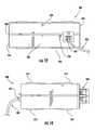
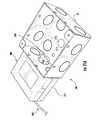
- FIG. 1is a bottom perspective view of a system for controlling one or more lights according to an embodiment of the subject matter described herein;
- FIG. 2is an exploded view showing a sensing device according to an embodiment of the subject matter described herein;
- FIG. 3Ais a side view showing a sensing device according to an embodiment of the subject matter described herein;
- FIG. 3Bis a side view showing a main screw according to an embodiment of the subject matter described herein;
- FIG. 4Ais a bottom plan view showing a faceplate according to an embodiment of the subject matter described herein;
- FIG. 4Bis a bottom plan view showing a main screw according to an embodiment of the subject matter described herein;
- FIG. 5is a partially exploded view showing a sensing device according to an embodiment of the subject matter described herein;
- FIG. 6is a perspective view showing a sensing device according to an embodiment of the subject matter described herein;
- FIG. 7is a perspective view showing a sensing device according to an embodiment of the subject matter described herein;
- FIGS. 8 and 9are side views showing a sensing device according to an embodiment of the subject matter described herein;
- FIG. 10is a top plan view showing a sensing device according to an embodiment of the subject matter described herein;
- FIG. 11is a bottom plan view of the sensing device according to an embodiment of the subject matter described herein;
- FIG. 12is a rear view showing an interface according to an embodiment of the subject matter described herein;
- FIG. 13Ais a perspective view showing an interface according to an embodiment of the subject matter described herein;
- FIG. 13Bis a perspective view showing an interface according to an embodiment of the subject matter described herein;
- FIG. 14is a side view showing an interface according to an embodiment of the subject matter described herein;
- FIG. 15is a bottom plan view showing an interface according to an embodiment of the subject matter described herein;
- FIG. 16is a front view of an interface according to an embodiment of the subject matter described herein;
- FIG. 17Ais a front view showing a retention feature according to an embodiment of the subject matter described herein;
- FIG. 17Bis a side view showing a retention feature according to an embodiment of the subject matter described herein;
- FIGS. 19A-21Bare perspective and sectional views showing in detail a method of installing an interface to a support structure according to an embodiment of the subject matter described herein;
- FIG. 22is a schematic view showing multiple sensing devices connected to one interface according to an embodiment of the subject matter described herein.
- the present disclosurerelates to a system for controlling one or more lights utilizing at least an ambient light sensor.
- the systemcan comprise two parts: a sensing device and an interface.
- the sensing device and the interfacecan be configured for attachment to separate supporting structures.
- the interface and the sensing devicecan be in electronic communication with each other via wired or wireless means.
- the systemcan also be in electronic communication with said one or more lights, via wired or wireless means.
- the systemcan process data generated by the sensing device or can pass the data unprocessed onto one or more lights.
- the systemcan also be integrated into a lighting control system, which comprises one or more light fixtures or systems, or it can function on its own.
- a system in accordance with the present disclosureis designed to control one or more lights and to securely attach to at least one supporting structure.
- the systemcan control one or more lights, but can also share and receive information with other light fixtures, sensors, or systems.
- the systemcan interface with other electronics (e.g. a dimming control system) in order to gather daylight and occupancy information.
- the presently disclosed systemcan be employed as part of a network of similar systems or can be used on its own.
- the systemcan be strategically installed in the room to be lighted in order to enhance the system's lighting control options.
- the systemcan be operable based on external, environmental factors. For example, where the system is installed near entryways, windows, doors, etc., the system can be programmed to turn the lights on when someone enters a room, turn them off when that person leaves, and reduce the lighting output near sources of natural light, such as windows.
- each systemcan process sensor data provided by its own sensor, a similar system, or a lighting fixture, and process the sensor data according to the system's own internal logic to control operation of the one or more lights.
- each systemcan also receive control input from other systems, lighting fixtures, control nodes, light switches, and/or commissioning tools. The control input can be processed along with the sensor data, according to the internal logic, to further enhance the system's control of one or more lights.
- a system 100can comprise an interface 300 and a sensing device 200 .
- the sensing device 200 and the interface 300can be in electrical communication with each other, by either wired or wireless means.
- the interface 300 and the sensing device 200can be in electrical connection via cable 400 .
- Cable 400can be any suitable cable that provides electric connectivity, such as, but not limited to a RJ45, RJ25, or RJ14 cable.
- system 100can comprise an interface 300 and more than one sensing device 200 .
- three sensing devices 200are contemplated, but any number of sensing devices 200 can be suitable.
- the sensing devices 200 and the interface 300can be in electrical communication with each other, by either wired or wireless means, such as cable 400 .
- the sensing device 200can comprise a main body 240 , an inner body 230 , a first retaining member (or faceplate) 210 , and a second retaining member (or main screw) 220 , which can be coaxially aligned.
- the sensing device 200 and any or all sub-componentscan be composed of any suitable material, such as, but not limited to, plastic, metal, organic material, or a combination of such, and can be created with any suitable technique, such as forming, molding, or machining.
- the main body 240is at least substantially cylindrical, but can be any shape and/or substantially hollow.
- the main body 240can comprise a first end 250 and a second end 252 distal to the first end 250 .
- the first end 250can comprise a first opening 246 , which can be positioned at the axial center of the first end 250 or off-center.
- the first opening 246can be of any shape or size.
- the first opening 246can be substantially circular and can be positioned at the axial center of the first end 250 .
- the diameter of the first opening 246can be preferably smaller than the diameter of the first end 250 .
- the first opening 246can be notched in order to receive and secure a sensor, such as an occupancy sensor 268 .
- Second end 252can be closed or open to an interior of main body 240 .
- the main body 240can comprise a third opening 256 .
- Third opening 256can be located proximate to the second end 252 on an outside surface of the main body 240 .
- the third opening 256can be sized such that the cable 400 can pass through it.
- the main body 240can also comprise at least one threaded portion.
- the main body 240can comprise threaded portions 242 and 244 .
- the first threaded portion 242 and the second threaded portion 244can be located on the outside surface of the main body 240 and can be the same or a different gauge of threading.
- First threaded portion 242can be disposed towards the first end 250 of the main body 240
- the second threaded portion 244can be disposed towards the second end 252 of the main body 250 .
- the first threaded portion 242 and second threaded portion 244can take up equal or unequal areas on main body 240 . In FIG. 2 , for example, the first threaded portion 242 takes up less surface area than the second threaded portion 244 , and the first threaded portion 242 has a different gauge than the second threaded portion 244 .
- Sensing device 200can also include a faceplate 210 .
- Faceplate 210can comprise a centrally located opening 212 and an annular protrusion 214 .
- the opening 212can be partially or fully threaded on its inner surface so that it can engage the first threaded portion 242 of the main body 240 . Therefore, the threaded portion of opening 212 can have the same gauge as first threaded portion 242 and the diameter of opening 212 can be larger than the diameter of the first end 250 . (See, for e.g., FIG. 2 ).
- the depth of threaded opening 212can extend substantially above and/or below the annular protrusion 214 to accommodate first threaded portion 242 .
- Each of a top and bottom rim of the threaded opening 212can be flat, textured, or sloped.
- the top rim of the threaded opening 212can be sloped such that the annular protrusion 214 has a radially upward slope towards the top rim of the threaded opening 212 .
- the bottom rimcan be similarly shaped like the top rim.
- annular protrusion 214can have a disk-shaped surface that extends perpendicularly away from a longitudinal axis of retaining member 210 .
- the annular protrusion 214can also have a circumferential edge with any thickness.
- the thickness of the circumferential edge of the annular protrusion 214can be less than the depth from which the threaded opening 212 extends, so that faceplate 210 can look substantially T-shaped. (See, for e.g., FIG. 3A ).
- Faceplate 210can also comprise a plurality of curved struts 218 , which can be disposed radially underneath the disk-shaped surface of the annular protrusion 214 . (See, for e.g. FIG. 4A ).
- the struts 218can be shaped such that the top face of every strut 218 is on the same plane and at the same level as an outside edge of the first portion 214 .
- the remote sensing device 200can also comprise a main screw 220 .
- the main screw 220can comprise a centrally located opening 222 and an annular protrusion 224 .
- the opening 222can be partially or fully threaded on its inner surface so that it can engage second threaded portion 244 of the main body 240 . Therefore, the threaded portion of opening 222 can have the same gauge as second threaded portion 244 and the diameter of opening 222 can be larger than the diameter of the second end 252 . (See, for e.g., FIG. 2 ).
- the depth of threaded opening 222can extend substantially below a surface of first portion 224 to accommodate the second threaded portion 244 .
- annular protrusion 224can have a disk-shaped surface that extends perpendicularly away from the longitudinal axis of main screw 220 .
- the annular protrusion 224can have a circumference that can be larger than the circumference of the annular protrusion 214 .
- a circumferential edge of the annular protrusion 224can have any thickness.
- the thickness of the circumferential edge of the annular protrusion 224can be less than the depth from which the threaded opening 222 extends, so that main screw 220 can be substantially T-shaped. (See, for e.g., FIG. 3B ).
- Main screw 220can also comprise a plurality of curved struts 228 , which can be disposed radially underneath the disk-shaped surface of annular protrusion 224 . (See, for e.g. FIG. 4B ).
- the struts 228can be shaped such that the top face of every strut 228 is on the same plane and at the same level as an outside edge of the first portion 224 .
- the struts 228can be substantially triangular.
- the sensing device 200can also comprise an inner body 230 .
- the inner body 230can be substantially cylindrical and can be sized such that it can have an external diameter smaller than an internal diameter of the main body 240 . This can allow the main body 240 to wholly receive the inner body 230 within its inner hollow cavity.
- the inner body 230can also comprise a slit 236 oriented parallel to the longitudinal axis of the main body 230 and running lengthwise along an outer surface of the inner body 230 .
- the slit 236can run from one end of the inner body 230 to any distance less than a length of the inner body, and can be wide enough to fit a diameter of cable 400 .
- the inner body 230can also comprise a substantially planar bottom surface 232 with a diameter that can be larger than the external diameter of the inner body 230 , and can be substantially the same diameter as the external diameter of the main body 240 .
- An electrical connectorsuch as for example electrical connector 272 can be disposed through the opening through inner body 230 and can be used for providing electrical contact to any components on substrate 262 .
- the sensing device 200can comprise a sensor feature 260 .
- sensor feature 260can comprise a substrate 262 and at least an ambient light sensor 266 .
- sensor feature 260can include an occupancy sensor 268 .
- the substrate 262can be substantially circular, while outer edges of substrate 262 can include notches, which coincide with alignment features 238 disposed on a top edge of the inner body 230 .
- the diameter of substrate 262can be substantially the same as the diameter of the inner body 230 .
- outer circumferences of substrate 262 and inner body 230can be in substantial alignment and the notches can receive alignment features 238 in order to create an integral fit between the two components.
- Ambient light sensor 266can be configured to detect a broad band of visible light or be configured to receive and/or filter out select bands of the visible and invisible light spectrum. For example, if the total amount of ambient light to be detected includes sunlight, an ambient light sensor capable of detecting a broad range of light can be used. If the sensing device 200 is positioned so that the total amount of light to be detected does not include sunlight and/or infrared light, an ambient light sensor can be provided with a special coating that filters out red light in the visible and infrared spectrum. Ambient light sensor 266 can be mounted on and electrically connected to substrate 262 , centrally or peripherally. In one aspect, ambient light sensor 266 can be mounted proximal to the edge of substrate 262 .
- a light pipe 270can be disposed over ambient light sensor 266 and can be configured to be secured to the main body 240 .
- Light pipe 270can be secured to the main body 240 by alignment tabs deliberately disposed on an edge of ambient light sensor 266 , positioned such that alignment tabs and notches at second opening 248 are in substantial alignment.
- the notches at second opening 248receive and retain the alignment tabs, thus securing ambient light sensor 266 within the main body 240 .
- sensing device 200can include the occupancy sensor 268 .
- Occupancy sensor 268can be centrally mounted on the substrate 262 , directly or on a spacer.
- Occupancy sensor 268can be electrically connected to the substrate 262 .
- Sensor feature 260can also comprise a lens 264 disposed over occupancy sensor 268 .
- Occupancy sensor 268 and/or lens 264can be secured to the main body 240 by alignment tabs deliberately disposed on an edge of occupancy sensor 268 , positioned such that alignment tabs and notches at first opening 246 are in substantial alignment.
- the notches at first opening 246receive and retain the alignment tabs, thus securing occupancy sensor 268 within the main body 240 .
- FIG. 5the main body 240 , the inner body 230 and the sensor feature 260 have been coupled to one another in order to form an integral cylindrical unit.
- Slit 236 and third opening 256can be aligned such that cable 400 can exit from the interior of the inner body 230 .
- Faceplate 210 and main screw 220are threadable onto main body 240 .
- FIGS. 6-11illustrate various views of sensing device 200 with both the faceplate 210 and main screw 220 threaded onto the main body 240 .
- Faceplate 210can be threaded either partially or totally onto first threaded surface 242 located at the first end 250 .
- Main screw 220can be partially or totally threaded onto second threaded portion 244 located at the second end 252 .
- main screw 220By rotating main screw 220 counterclockwise about the positive z-axis of the main body 240 the main screw 220 will be threaded further onto the main body 240 , towards the first end 250 . Conversely, by rotating the main screw 220 clockwise about the positive z-axis of the main body 240 , the main screw 220 can be removed from the main body 240 .
- the interface 300can comprise an enclosure 310 and a retention feature 350 .
- the interface 300 and any component piecescan be molded, machined or assembled.
- the interface 300can be made entirely out of any suitable material, such as, but not limited to, plastic, metal, or organic material or interface 300 can be made with some combination of materials.
- the enclosure 310can be any shape or size and can be configured to contain electronics, such as, but not limited to, a driver module and/or a communications module.
- FIGS. 12-16illustrate various views of the interface 300 .
- the enclosure 310can comprise a first pair of faces 330 , a second pair or faces 332 , and a third pair of faces 334 .
- the first pair of faces 330can have a larger surface area than the second pair of faces 332 and/or the third pair of faces 334 .
- the first pair of faces 330 , the second pair of faces 332 , and the third pair of faces 334can all be opposing pairs.
- the first pair of faces 330 , the second pair of faces 332 and the third pair of faces 334can form a rectangular prism, where the pairs of faces have varying dimensions. (See, for e.g., FIG. 12 ).
- the enclosure 310can comprise one or more openings.
- a first opening 320can be disposed on one of the second pair of faces 332 .
- the first opening 320can be located centrally between the first pair of faces 330 . (See, for e.g., FIG. 12 ).
- the first opening 320can also be located substantially off the center between the third pair of faces 334 .
- the first opening 320can be any shape and can be sized such that a cable, cord, or wire can pass through.
- first opening 320can be an internal via provided on one of the second pair of faces 332 that is distal to the retention feature 350 , such that a power cable (i.e. an AC cable) connectable to external devices is passed through first opening 320 .
- a power cablei.e. an AC cable
- Enclosure 310can also comprise a second opening 322 .
- Second opening 322can be disposed on one of the second pair of faces 332 . More specifically, the second opening 322 can be disposed in the face distal to the face with the first opening. The second opening 322 can be centrally located on this face and/or can be substantially circular. (See, for e.g. FIG. 19B ).
- the enclosure 310can also comprise a port 324 .
- Port 324can be any port configured for an electrical connection, such as cable 400 .
- Port 324can be configured to receive any standard cable connector, such as, but not limited to, an RJ45, RJ25, or RJ14 cable for interfacing with a dimming control system
- port 324is an eight position eight contact jack (8P8C). (See, for e.g., FIGS. 12 and 15 ).
- Enclosure 310can also comprise a trough 340 .
- Trough 340can run medially around an exterior of the enclosure 310 , such that the trough 340 runs substantially parallel to first pair of faces 330 .
- Trough 340can be disposed solely on the second pair of faces 332 and/or the third pair of faces 334 . (See, for e.g., FIG. 12 ).
- the enclosure 310can also comprise one or more rib features 312 . Rib features 312 can be placed on each of the first pair of faces 330 . Rib features 312 can comprise a raised ridgeline, with a downward slope on both sides off the ridge.
- Rib feature 312can have a substantially L-shaped ridgeline that can be positioned proximate to edges and/or corners of each of the first pair of faces 330 . Each side of the first pair of faces 330 can have a plurality of rib features 312 . (See, for e.g., FIGS. 13A and 13B ).
- the enclosure 310can additionally include a plurality of protrusions 368 . As in FIGS. 13A and 13B , the protrusions 368 can be located on one of the second pair of faces 332 (e.g on the second face that contains the retention feature 350 ), and can extend between the first pair of faces 330 .
- the protrusions 368can be of any shape and/or size. In one aspect, the protrusions 368 can have a profile that is semi-circular and can protrude from the enclosure 310 less than the retention feature 350 does.
- Retention feature 350can be provided on one of the second pairs of faces 332 and can comprise a body 358 and at least one tab 352 . (See, for e.g., FIGS. 17A and 17B ).
- Body 358can be of any shape and size. In one aspect, body 358 can be substantially cylindrical and can be smaller than the enclosure 310 . One end of the body 358 can be integral with or attached separately to enclosure 310 .
- the body 358can have a passage 356 , which runs through a length of the body 358 . Passage 356 can have a width that remains constant through the length of the passage 356 or it can vary in width throughout the length of body 358 . In one aspect, the passage 356 can be annular.
- the body 358can be positioned over the second opening 322 in enclosure 310 , such that the passage 356 can be aligned with the second opening 322 , thereby allowing cable(s) to exit the enclosure 310 through opening 322 and passage 356 .
- the body 358can also have a top portion 362 .
- Top portion 362can be substantially annular in shape. In one aspect, the top portion 362 can have a larger diameter than a diameter of the body 358 .
- the top portion 362can have an opening 366 that can align with passage 356 . In one aspect, opening 366 can be circular and can have a smaller diameter than a diameter of the top portion 362 .
- Retention feature 350can also include at least one tab 352 that can be attached onto or integral to top portion 362 and/or body 358 .
- the at least one tab 352can be angled off of the top portion 362 , such that there can be open space between the body 358 and the tab 352 .
- the tab 352 and top portion 362can be constructed such that the tab 352 can be elastically displaced one direction; whereby, pressure applied to an outer surface of the tab 352 elastically displaces the tab 352 inward towards the body 358 .
- the retention feature 350can comprise a plurality of tabs 352 .
- the plurality of tabs 352can comprise tabs of different lengths and sizes.
- the tabs 352can be in opposing pairs. The pairs can be the same as or different from each other. In another aspect, there can be two opposing pairs of tabs 352 , and one pair can be longer than the other.
- Tabs 352can be sized such that when pressure is applied to the tab 352 , each of such tabs 352 can displace a specified amount with regard to an original resting position, as in FIG. 20B .
- the amount of displacementcan be determined by the material that the tab 352 is manufactured out of, such as a polycarbonate (PC) resin.
- PCpolycarbonate
- Each of tabs 352can be of any length less than the distance from the top portion 362 to one of the second pairs of faces 332 that the retention feature 350 can be attached to, and can be of a short enough length that there can be a gap between the end of the tab 352 and the surface of the face 332 .
- Each of tabs 352can have any shape or form, such as, but not limited to, rectangular, L-shaped, or triangular.
- each of tabs 352can have a substantially triangular form, where the narrowest part of the tab is attached to the top portion 362 .
- a surface of each of the tabs 352can be angled such that the surface of each of the tabs 352 angles out from the top portion 362 at a specified angle.
- the end of tabs 352 distal to the top portion 362can comprise one or more detents 360 integrated into a surface of the tab 352 , where such detents 360 can secure the retention feature 350 within a variety of differently sized openings in a support structure.
- Detents 360can take the form of a step feature, a ridge, or a notch.
- detents 360 on a tabsuch as tabs 352
- the greater the versatility the retention feature can haveas more detents 360 can enable the retention feature 350 to fit within a larger variety of different sized openings.
- detents 360 in the form of a step featurecan be integrated into the edge of tab 352 that is distal to the main body 358 .
- Such detents 360can be formed to catch onto an edge of an opening in a support structure, such as a junction box with a half-inch (1 ⁇ 2 in.) opening or knockout, to permit the interface 300 to removably attach or secure to an interior of the support structure.
- the sensing device 200 and the interface 300can be attached and installed onto different retaining structures.
- the sensing device 200can attach to a retaining structure S 1 by faceplate 210 and main screw 220 .
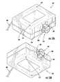
- FIGS. 18A-18Cillustrate installation of the sensor assembly 200 into the retaining structure S 1 , for example a ceiling.
- the structure S 1can be of any shape or size, with at least one flat surface.
- the structure S 1can also have an opening P 1 , which can be formed or cut-out, through the flat surface.
- the opening P 1can be substantially circular and sized so that the main body 240 of the sensing device 200 can pass through it, but the faceplate 210 and the main screw 220 cannot.
- the diameter of the opening P 1can be larger than the diameter of the main body 240 , but smaller than the diameters of the annular protrusion 214 and annular protrusion 224 .
- Structure S 1can have a wall thickness at or less than the length of the main body 240 .
- the structure S 1can have a thickness between approximately 6 mm and 43 mm or any sub-range thereof.
- sensing device 200In order to install sensing device 200 in structure S 1 , faceplate 210 and main screw 220 can be removed from the main body 240 .
- the sensing device 200can be inserted through the opening P 1 , such that the second end 252 of the main body 240 is positioned behind the structure S 1 .
- the first end 250 of the main body 240can be introduced through opening P 1 , while the second end 252 can remain behind structure S 1 .
- FIG. 18Bonce the main body 240 has been inserted, the faceplate 210 and the main screw 220 can then be threaded onto the first end 250 and the second end 252 , respectively.
- the faceplate 210 and main screw 220can be adjusted such that the bottom surface of the annular protrusion 214 and the top surface of the annular protrusion 224 abut opposing surfaces of structure S 1 . (See, for e.g., FIG. 18C ).
- the main screw 220can be adjusted to accommodate different thicknesses.
- Main screw 220can be threaded further up on the main body 240 by rotating the main screw 220 counterclockwise with respect to the positive z-axis, while the main screw 220 can be removed by rotating the second retaining member clockwise with respect to the positive z-axis.
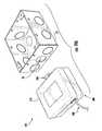
- FIGS. 19A-21Billustrate, without limitation, an example of installation of the interface 300 into retaining structure S 2 , such as a junction box.
- the interface 300can be attached to a retaining structure S 2 by retention feature 350 .
- structure S 2can, for example, have a wall thickness approximately the distance between the enclosure 310 and the detents 360 .
- the structure S 2can have an opening P 2 , which can be formed or cut-out, through a flat surface of S 2 . (See, for e.g., FIGS. 19A-B ).
- the opening P 2can be sized such that the top portion 362 of the retention feature 350 can fit through opening P 2 , but the outermost portions of the tabs 352 can be too wide.
- the diameter of the opening P 2can be larger than the diameter of the top portion 362 , except the total width of the tabs 352 in the original resting position is larger than the opening P 2 .
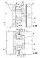
- the tabs 352can elastically flex towards the body 358 to allow the retention feature 350 to fully enter opening P 2 , as in FIGS. 20A-B .
- the face 332is substantially flush against the flat surface of structure S 2
- at least one detent 360can catch onto the opposing surface of structure S 2 to secure the retention feature 350 within an interior of support structure S 2 .
- the face 332 of the enclosure 310does not have to be substantially flush against the flat surface of structure S 2 .
- the retention feature 350can have all, some, or none of the tabs displaced from their resting position.
- the elastic disposition of the tabsallows a wider range of opening P 2 sizes and structure S 2 thicknesses.
- To remove the retention feature 350 from structure S 2and thus disconnect the interface 300 from the support structure S 2 pressure need only be applied to the tabs 352 . This can elastically flex the tabs towards the body 358 and allow the retention feature 350 to be withdrawn from within the opening P 2 .
- the light fixtures described for example in U.S. patent applications Ser. Nos. 13/782,040 and 13/838,398can comprise light fixtures as described, the system 100 , and/or the system 100 plus one or more lights.
- the networks described in Ser. No. 13/782,040can comprise the described light fixtures, the system 100 , the system 100 plus one or more lights, or any combination of the former.
- the system 100can be grouped into a lighting zone with other systems 100 and/or lighting fixtures and can perform the same functions, such as entering lightcast mode and adjusting lighting levels based on sensor data.
- the system 100can send and receive data to and from other light fixtures or systems.
- the ambient light sensor 266can have a certain field of view, a task surface, and the system 100 can determine a set point for the one or more lights it controls.
Landscapes
- Physics & Mathematics (AREA)
- Spectroscopy & Molecular Physics (AREA)
- General Physics & Mathematics (AREA)
- Life Sciences & Earth Sciences (AREA)
- Sustainable Development (AREA)
- Engineering & Computer Science (AREA)
- Human Computer Interaction (AREA)
- Circuit Arrangement For Electric Light Sources In General (AREA)
- Arrangement Of Elements, Cooling, Sealing, Or The Like Of Lighting Devices (AREA)
Abstract
Description
Claims (15)
Priority Applications (1)
| Application Number | Priority Date | Filing Date | Title |
|---|---|---|---|
| US14/052,336US9622321B2 (en) | 2013-10-11 | 2013-10-11 | Systems, devices and methods for controlling one or more lights |
Applications Claiming Priority (1)
| Application Number | Priority Date | Filing Date | Title |
|---|---|---|---|
| US14/052,336US9622321B2 (en) | 2013-10-11 | 2013-10-11 | Systems, devices and methods for controlling one or more lights |
Publications (2)
| Publication Number | Publication Date |
|---|---|
| US20150102729A1 US20150102729A1 (en) | 2015-04-16 |
| US9622321B2true US9622321B2 (en) | 2017-04-11 |
Family
ID=52809123
Family Applications (1)
| Application Number | Title | Priority Date | Filing Date |
|---|---|---|---|
| US14/052,336Active2034-02-21US9622321B2 (en) | 2013-10-11 | 2013-10-11 | Systems, devices and methods for controlling one or more lights |
Country Status (1)
| Country | Link |
|---|---|
| US (1) | US9622321B2 (en) |
Cited By (17)
| Publication number | Priority date | Publication date | Assignee | Title |
|---|---|---|---|---|
| US9909723B2 (en) | 2015-07-30 | 2018-03-06 | Cree, Inc. | Small form-factor LED lamp with color-controlled dimming |
| US20180077779A1 (en)* | 2016-09-09 | 2018-03-15 | Abl Ip Holding Llc | Control modules having integral antenna components for luminaires and wireless intelligent lighting systems containing the same |
| US10323824B1 (en) | 2017-12-19 | 2019-06-18 | Cree, Inc. | LED light fixture with light shaping features |
| WO2019125925A1 (en) | 2017-12-19 | 2019-06-27 | Cree, Inc. | Lighting device with active thermal management |
| US20190342974A1 (en)* | 2018-05-04 | 2019-11-07 | Crestron Electronics, Inc. | Color temperature sensor |
| WO2019226411A1 (en) | 2018-05-24 | 2019-11-28 | Ideal Industries Lighting Llc | Led lighting device with led board on network |
| US10508794B2 (en) | 2017-09-21 | 2019-12-17 | Ideal Industries Lighting Llc | LED troffer fixture having a wide lens |
| US10544913B2 (en) | 2017-06-08 | 2020-01-28 | Ideal Industries Lighting Llc | LED wall-wash light fixture |
| WO2020205191A1 (en) | 2019-03-29 | 2020-10-08 | Ideal Industries Lighting Llc | Waveguide managing high power density |
| US11002605B2 (en)* | 2018-05-04 | 2021-05-11 | Crestron Electronics, Inc. | System and method for calibrating a light color sensor |
| US11035527B1 (en) | 2020-07-23 | 2021-06-15 | Ideal Industries Lighting Llc | Troffer light fixture |
| US11079079B2 (en) | 2017-09-21 | 2021-08-03 | Ideal Industries Lighting, LLC | Troffer light fixture |
| US20220277634A1 (en)* | 2017-07-10 | 2022-09-01 | Carrier Corporation | Hazard detector with optical status indicator |
| US11655950B2 (en) | 2014-03-15 | 2023-05-23 | Ideal Industries Lighting Llc | Lighting devices having optical waveguides for controlled light distribution |
| US11694525B2 (en) | 2017-07-10 | 2023-07-04 | Carrier Corporation | Hazard detector with optical status indicator |
| US11781732B2 (en) | 2021-12-22 | 2023-10-10 | Ideal Industries Lighting Llc | Lighting fixture with lens assembly for reduced glare |
| US12094326B2 (en) | 2018-03-30 | 2024-09-17 | Carrier Corporation | Lens for a visual alarm detector |
Families Citing this family (25)
| Publication number | Priority date | Publication date | Assignee | Title |
|---|---|---|---|---|
| USD739359S1 (en) | 2013-10-11 | 2015-09-22 | Cree, Inc. | Lighting control device |
| US9488767B2 (en) | 2014-08-05 | 2016-11-08 | Cree, Inc. | LED based lighting system |
| US10531545B2 (en) | 2014-08-11 | 2020-01-07 | RAB Lighting Inc. | Commissioning a configurable user control device for a lighting control system |
| US9851077B2 (en) | 2015-02-25 | 2017-12-26 | Cree, Inc. | LED lamp with compact fluorescent lamp form factor |
| US9903576B2 (en) | 2015-06-15 | 2018-02-27 | Cree, Inc. | Lighting apparatus with electrical connector and control module |
| US9786639B2 (en) | 2015-12-03 | 2017-10-10 | Cree, Inc. | Solid state light fixtures suitable for high temperature operation having separate blue-shifted-yellow/green and blue-shifted-red emitters |
| US10211660B2 (en) | 2016-02-08 | 2019-02-19 | Cree, Inc. | LED lighting device with adaptive profiles for controlling power consumption |
| US10234127B2 (en) | 2016-02-08 | 2019-03-19 | Cree, Inc. | LED luminaire having enhanced thermal management |
| US9995441B2 (en) | 2016-02-08 | 2018-06-12 | Cree, Inc. | LED lamp with internal reflector |
| US9961750B2 (en) | 2016-02-24 | 2018-05-01 | Leviton Manufacturing Co., Inc. | Advanced networked lighting control system including improved systems and methods for automated self-grouping of lighting fixtures |
| US10416377B2 (en) | 2016-05-06 | 2019-09-17 | Cree, Inc. | Luminaire with controllable light emission |
| US11719882B2 (en) | 2016-05-06 | 2023-08-08 | Ideal Industries Lighting Llc | Waveguide-based light sources with dynamic beam shaping |
| US10405406B2 (en) | 2016-06-23 | 2019-09-03 | Ideal Industries Lighting Llc | LED lighting device with communications module and antenna |
| US10508797B2 (en) | 2016-12-21 | 2019-12-17 | Ideal Industries Lighting Llc | Luminaire and connection mechanism for connecting multiple luminaires |
| US10274171B2 (en) | 2017-01-06 | 2019-04-30 | Cree, Inc. | Adjustable LED light fixture for use in a troffer |
| US10539308B2 (en) | 2017-02-06 | 2020-01-21 | Ideal Industries Lighting Llc | Modular overhead lighting system |
| USD927027S1 (en) | 2017-02-06 | 2021-08-03 | Ideal Industries Lighting Llc | LED troffer |
| US10302262B2 (en) | 2017-02-06 | 2019-05-28 | Cree, Inc. | LED troffer lens assembly mount |
| US10247372B2 (en) | 2017-02-06 | 2019-04-02 | Cree, Inc. | LED troffer lens assembly mount |
| US10260683B2 (en) | 2017-05-10 | 2019-04-16 | Cree, Inc. | Solid-state lamp with LED filaments having different CCT's |
| USD842821S1 (en)* | 2017-09-08 | 2019-03-12 | Franklin B White | Set of signalling switch and indicator light assembly |
| JP7016056B2 (en)* | 2018-02-22 | 2022-02-04 | パナソニックIpマネジメント株式会社 | lighting equipment |
| EP3629033A1 (en)* | 2018-09-26 | 2020-04-01 | Friedrich Brück | Light detection unit for light detection for a constant light control for at least one presence detector and presence detector with at least one such light detection unit |
| CN119676512A (en) | 2019-01-09 | 2025-03-21 | 杜比实验室特许公司 | Display management with ambient light compensation |
| CA3200726A1 (en) | 2020-09-07 | 2022-03-10 | Ideal Industries Lighting Llc | Light strip |
Citations (155)
| Publication number | Priority date | Publication date | Assignee | Title |
|---|---|---|---|---|
| USD255031S (en) | 1978-03-06 | 1980-05-20 | Scientific Technology, Inc. | Housing for photoelectric sensor and control circuit responsive thereto |
| USD259514S (en) | 1978-09-01 | 1981-06-09 | Welch James D | Decorative lamp |
| US4839533A (en) | 1986-11-24 | 1989-06-13 | Aga Steven M | Remote safety switch |
| USD317363S (en) | 1988-07-29 | 1991-06-04 | Welch James D | Decorative lamp |
| US5079680A (en) | 1991-06-07 | 1992-01-07 | Reflector Hardware Corporation | Undershelf task light fixture |
| USD333294S (en) | 1991-06-21 | 1993-02-16 | John Dossey | Automobile hot wire prevention switch |
| USD344361S (en) | 1992-04-03 | 1994-02-15 | Reflector Hardware Corporation | Desk lamp |
| USD349582S (en) | 1992-04-03 | 1994-08-09 | Reflector Hardware Corporation | Tiltable desk lamp |
| US5471119A (en) | 1994-06-08 | 1995-11-28 | Mti International, Inc. | Distributed control system for lighting with intelligent electronic ballasts |
| US5486984A (en)* | 1991-08-19 | 1996-01-23 | Miller; Jack V. | Parabolic fiber optic luminaire |
| USD373438S (en) | 1994-10-11 | 1996-09-03 | Light Corporation | Desk lamp |
| JPH11345690A (en) | 1998-06-03 | 1999-12-14 | Toshiba Lighting & Technology Corp | Lighting system |
| USD419964S (en) | 1999-02-19 | 2000-02-01 | Holce Kent J | Combination current sensor relay housing |
| US6118230A (en) | 1998-01-30 | 2000-09-12 | Hewlett-Packard Company | Lighting control system including server for receiving and processing lighting control requests |
| US6137408A (en) | 1998-06-09 | 2000-10-24 | Keyence Corporation | Controller for plural area sensors |
| US6160359A (en) | 1998-01-30 | 2000-12-12 | Hewlett-Packard Company | Apparatus for communicating with a remote computer to control an assigned lighting load |
| US6166496A (en) | 1997-08-26 | 2000-12-26 | Color Kinetics Incorporated | Lighting entertainment system |
| WO2001026334A2 (en) | 1999-10-06 | 2001-04-12 | Sensoria Corporation | Method and apparatus for sensor networking |
| WO2001026335A2 (en) | 1999-10-06 | 2001-04-12 | Sensoria Corporation | Distributed signal processing in a network |
| WO2001026068A1 (en) | 1999-10-06 | 2001-04-12 | Sensoria Corporation | Wireless networked sensors |
| WO2002039242A1 (en) | 2000-10-31 | 2002-05-16 | Millennial Net, Inc. | Networked processing system with optimized power efficiency |
| CA2426769A1 (en) | 2000-11-17 | 2002-05-23 | Eimar M. Boesjes | Distributed wireless online access system |
| CA2511368A1 (en) | 2000-11-17 | 2002-05-23 | Eimar M. Boesjes | Distributed wireless online access system |
| US6396040B1 (en) | 1998-10-12 | 2002-05-28 | Control Devices, Inc. | Ambient light sensor |
| US6437692B1 (en) | 1998-06-22 | 2002-08-20 | Statsignal Systems, Inc. | System and method for monitoring and controlling remote devices |
| US6528954B1 (en) | 1997-08-26 | 2003-03-04 | Color Kinetics Incorporated | Smart light bulb |
| WO2003047175A1 (en) | 2001-11-28 | 2003-06-05 | Millennial Net | Etwork protocol for an ad hoc wireless network |
| US20040002792A1 (en) | 2002-06-28 | 2004-01-01 | Encelium Technologies Inc. | Lighting energy management system and method |
| US6735630B1 (en) | 1999-10-06 | 2004-05-11 | Sensoria Corporation | Method for collecting data using compact internetworked wireless integrated network sensors (WINS) |
| US6826607B1 (en) | 1999-10-06 | 2004-11-30 | Sensoria Corporation | Apparatus for internetworked hybrid wireless integrated network sensors (WINS) |
| US6832251B1 (en) | 1999-10-06 | 2004-12-14 | Sensoria Corporation | Method and apparatus for distributed signal processing among internetworked wireless integrated network sensors (WINS) |
| WO2004109966A2 (en) | 2003-06-05 | 2004-12-16 | Millennial Net | Protocol for configuring a wireless network |
| US6859831B1 (en) | 1999-10-06 | 2005-02-22 | Sensoria Corporation | Method and apparatus for internetworked wireless integrated network sensor (WINS) nodes |
| US6914893B2 (en) | 1998-06-22 | 2005-07-05 | Statsignal Ipc, Llc | System and method for monitoring and controlling remote devices |
| US6990394B2 (en) | 2002-12-24 | 2006-01-24 | Pasternak Barton A | Lighting control system and method |
| US7005802B2 (en) | 2002-05-30 | 2006-02-28 | Hubbell Incorporated | Retrofit kit for modular lamp controller |
| US20060044152A1 (en) | 2002-09-04 | 2006-03-02 | Ling Wang | Master-slave oriented two-way rf wireless lighting control system |
| US7020701B1 (en) | 1999-10-06 | 2006-03-28 | Sensoria Corporation | Method for collecting and processing data using internetworked wireless integrated network sensors (WINS) |
| US7031920B2 (en) | 2000-07-27 | 2006-04-18 | Color Kinetics Incorporated | Lighting control using speech recognition |
| US20060181416A1 (en) | 2005-02-02 | 2006-08-17 | Chen Kai-Po | Bulb with sensing function |
| US7095056B2 (en) | 2003-12-10 | 2006-08-22 | Sensor Electronic Technology, Inc. | White light emitting device and method |
| US7093431B2 (en) | 2003-01-11 | 2006-08-22 | J. Eberspächer GmbH & Co. KG | Exhaust gas treatment device |
| US7103511B2 (en) | 1998-10-14 | 2006-09-05 | Statsignal Ipc, Llc | Wireless communication networks for providing remote monitoring of devices |
| WO2006130662A2 (en) | 2005-06-01 | 2006-12-07 | Millennial Net, Inc. | Communicating over a wireless network |
| US20070132405A1 (en) | 2002-09-04 | 2007-06-14 | Hillis W D | General operating system |
| USD549663S1 (en) | 2006-11-16 | 2007-08-28 | Hiwin Mikrosystem Corp. | Control box of actuator |
| WO2007102097A1 (en) | 2006-03-07 | 2007-09-13 | Philips Intellectual Property & Standards Gmbh | Lighting system with lighting units using optical communication |
| US7272027B2 (en) | 1999-09-23 | 2007-09-18 | Netlogic Microsystems, Inc. | Priority circuit for content addressable memory |
| US7305467B2 (en) | 2002-01-02 | 2007-12-04 | Borgia/Cummins, Llc | Autonomous tracking wireless imaging sensor network including an articulating sensor and automatically organizing network nodes |
| USD560006S1 (en) | 2007-06-09 | 2008-01-15 | Light Corporation | Reminder light |
| US7330115B1 (en) | 2005-02-18 | 2008-02-12 | Zuba John P | Electronic device control system |
| US7333903B2 (en) | 2005-09-12 | 2008-02-19 | Acuity Brands, Inc. | Light management system having networked intelligent luminaire managers with enhanced diagnostics capabilities |
| US7344279B2 (en) | 2003-12-11 | 2008-03-18 | Philips Solid-State Lighting Solutions, Inc. | Thermal management methods and apparatus for lighting devices |
| USD565771S1 (en) | 2007-06-09 | 2008-04-01 | Light Corporation | Gooseneck lamp |
| US7357530B2 (en) | 2005-07-15 | 2008-04-15 | Bwt Property, Inc. | Lighting apparatus for navigational aids |
| USD567431S1 (en) | 2007-06-09 | 2008-04-22 | Light Corporation | Desk lamp |
| US7369060B2 (en) | 2004-12-14 | 2008-05-06 | Lutron Electronics Co., Inc. | Distributed intelligence ballast system and extended lighting control protocol |
| HK1114508A (en) | 2005-06-01 | 2008-10-31 | Millennial Net, Inc. | Communicating over a wireless network |
| USD580886S1 (en) | 2007-07-27 | 2008-11-18 | Karl Harman | Controller for operating a wildlife feeder |
| USD582598S1 (en) | 2007-06-07 | 2008-12-09 | Light Corporation | Light assembly |
| WO2009011898A2 (en) | 2007-07-17 | 2009-01-22 | I/O Controls Corporation | Control network for led-based lighting system in a transit vehicle |
| US7482567B2 (en) | 2004-09-24 | 2009-01-27 | Koninklijke Philips Electronics N.V. | Optical feedback system with improved accuracy |
| US7484008B1 (en) | 1999-10-06 | 2009-01-27 | Borgia/Cummins, Llc | Apparatus for vehicle internetworks |
| USD586950S1 (en) | 2007-06-09 | 2009-02-17 | Light Corporation | Rail |
| USD587390S1 (en) | 2007-06-09 | 2009-02-24 | Light Corporation | Rail light |
| USD588064S1 (en) | 2007-06-09 | 2009-03-10 | Light Corporation | USB assembly |
| US7550931B2 (en) | 2001-05-30 | 2009-06-23 | Philips Solid-State Lighting Solutions, Inc. | Controlled lighting methods and apparatus |
| WO2009145747A1 (en) | 2007-05-24 | 2009-12-03 | Face Bradbury R | Lighting fixture with low voltage transformer & self-powered switching system |
| US20090305644A1 (en) | 2008-06-10 | 2009-12-10 | Millennial Net, Inc. | System and method for a wireless controller |
| US20090302996A1 (en) | 2008-06-10 | 2009-12-10 | Millennial Net, Inc. | System and method for a management server |
| US20090302994A1 (en) | 2008-06-10 | 2009-12-10 | Mellennial Net, Inc. | System and method for energy management |
| WO2009151416A1 (en) | 2008-06-10 | 2009-12-17 | Millennial Net, Inc. | System and method for energy management |
| US20090315668A1 (en) | 2008-06-19 | 2009-12-24 | Light Corporation | Wiring topology for a building with a wireless network |
| WO2009158514A1 (en) | 2008-06-26 | 2009-12-30 | Telelumen, LLC | Authoring, recording, and replication of lighting |
| US7646029B2 (en) | 2004-07-08 | 2010-01-12 | Philips Solid-State Lighting Solutions, Inc. | LED package methods and systems |
| US7683301B2 (en) | 2006-02-08 | 2010-03-23 | The Regents Of The University Of California | Method for preventing incorrect lighting adjustment in a daylight harvesting system |
| US20100084992A1 (en) | 2008-05-16 | 2010-04-08 | Charles Bernard Valois | Intensity control and color mixing of light emitting devices |
| US20100203515A1 (en) | 2006-12-22 | 2010-08-12 | Rudolf Rigler | Detection of gene expression in cells by scanning fcs |
| US7804252B2 (en) | 2008-04-02 | 2010-09-28 | Chia-Teh Chen | Two way lighting control system with dual illumination sources |
| WO2010122457A2 (en) | 2009-04-24 | 2010-10-28 | Koninklijke Philips Electronics N.V. | System for controlling a plurality of light sources |
| US7839017B2 (en) | 2009-03-02 | 2010-11-23 | Adura Technologies, Inc. | Systems and methods for remotely controlling an electrical load |
| US20100294915A1 (en) | 2009-05-21 | 2010-11-25 | Williams Jonathan D | Occupancy sensor and override unit for photosensor-based control of load |
| US7924174B1 (en) | 2006-05-26 | 2011-04-12 | Cooper Technologies Company | System for controlling a lighting level of a lamp in a multi-zone environment |
| US7924927B1 (en) | 2005-03-21 | 2011-04-12 | Boesjes Eimar M | Distributed functionality in a wireless communications network |
| WO2011070058A2 (en) | 2009-12-08 | 2011-06-16 | Tridonic Ag | Controllable retrofit led lamps and lighting system having an led lamp |
| WO2011087681A1 (en) | 2010-01-13 | 2011-07-21 | Masco Corporation | Low voltage control systems and associated methods |
| WO2011090938A1 (en) | 2010-01-19 | 2011-07-28 | Millennial Net, Inc. | Systems and methods utilizing a wireless mesh network |
| US8035320B2 (en) | 2007-04-20 | 2011-10-11 | Sibert W Olin | Illumination control network |
| WO2011152968A1 (en) | 2010-06-02 | 2011-12-08 | Millennial Net, Inc. | System and method for low latency sensor network |
| EP2440017A2 (en) | 2010-09-15 | 2012-04-11 | Saf-t-Glo Limited | Lighting Systems |
| US8159156B2 (en) | 2009-08-10 | 2012-04-17 | Redwood Systems, Inc. | Lighting systems and methods of auto-commissioning |
| US20120136485A1 (en) | 2010-11-19 | 2012-05-31 | Weber Theodore E | Control System and Method for Managing Wireless and Wired Components |
| US20120139426A1 (en) | 2010-12-03 | 2012-06-07 | General Electric Company | Dimmable outdoor luminaires |
| US8226272B2 (en) | 2005-03-31 | 2012-07-24 | Neobulb Technologies, Inc. | Illuminating equipment using high power LED with high efficiency of heat dissipation |
| US8228163B2 (en) | 2005-03-12 | 2012-07-24 | Lutron Electronics Co., Inc. | Handheld programmer for lighting control system |
| US20120206050A1 (en) | 2002-07-12 | 2012-08-16 | Yechezkal Evan Spero | Detector Controlled Illuminating System |
| WO2012112813A2 (en) | 2011-02-19 | 2012-08-23 | Telelumen Llc | Systems and methods for developing and distributing illumination data files |
| WO2012125502A2 (en) | 2011-03-11 | 2012-09-20 | Telelumen, LLC | Luminaire system |
| US20120235579A1 (en) | 2008-04-14 | 2012-09-20 | Digital Lumens, Incorporated | Methods, apparatus and systems for providing occupancy-based variable lighting |
| US8275471B2 (en) | 2009-11-06 | 2012-09-25 | Adura Technologies, Inc. | Sensor interface for wireless control |
| US8274928B2 (en) | 2007-06-18 | 2012-09-25 | Light Corporation | Wireless mesh network |
| US8280558B2 (en) | 2010-04-01 | 2012-10-02 | ESI Ventures, LLC | Computerized light control system with light level profiling and method |
| US8315237B2 (en) | 2008-10-29 | 2012-11-20 | Google Inc. | Managing and monitoring emergency services sector resources |
| US8324838B2 (en) | 2008-03-20 | 2012-12-04 | Cooper Technologies Company | Illumination device and fixture |
| US20120313533A1 (en) | 2011-06-07 | 2012-12-13 | Wen-Sung Hu | Intelligent and Energy-Saving LED Lamp with Glimmer and Full Light Emission |
| US8344660B2 (en) | 2009-12-16 | 2013-01-01 | Enlighted, Inc. | Lighting control |
| US20130013091A1 (en) | 2010-03-29 | 2013-01-10 | Koninklijke Philips Electronics, N.V. | Network of Heterogeneous Devices Including at Least One Outdoor Lighting Fixture Node |
| US20130021792A1 (en) | 2011-07-24 | 2013-01-24 | Cree, Inc. | Modular indirect suspended/ceiling mount fixture |
| US8364325B2 (en) | 2008-06-02 | 2013-01-29 | Adura Technologies, Inc. | Intelligence in distributed lighting control devices |
| US8445826B2 (en) | 2007-06-29 | 2013-05-21 | Orion Energy Systems, Inc. | Outdoor lighting systems and methods for wireless network communications |
| US8450670B2 (en) | 2007-06-29 | 2013-05-28 | Orion Energy Systems, Inc. | Lighting fixture control systems and methods |
| US8497634B2 (en) | 2008-10-23 | 2013-07-30 | Innovation Works, Inc. | Wireless lighting system for staircases and passageways |
| US20130200805A1 (en) | 2008-10-24 | 2013-08-08 | Ilumisys, Inc. | Light and light sensor |
| US8508137B2 (en) | 2009-05-20 | 2013-08-13 | Express Imaging Systems, Llc | Apparatus and method of energy efficient illumination |
| US20130207552A1 (en)* | 2010-10-22 | 2013-08-15 | Koninklijke Philips Electronics N.V. | Integral troffer motion detector |
| US20130207553A1 (en) | 2008-02-19 | 2013-08-15 | Lutron Electronics Co., Inc. | Load Control SystemHaving a Rotary Actuator |
| US20130210252A1 (en) | 2010-10-07 | 2013-08-15 | General Electric Company | Controller device |
| US8519714B2 (en) | 2010-06-18 | 2013-08-27 | Xicato, Inc. | LED-based illumination module on-board diagnostics |
| US8536792B1 (en) | 2012-03-23 | 2013-09-17 | Honeywell International Inc. | System and method for distributed lighting device control |
| US8536802B2 (en) | 2009-04-14 | 2013-09-17 | Digital Lumens Incorporated | LED-based lighting methods, apparatus, and systems employing LED light bars, occupancy sensing, and local state machine |
| US8536984B2 (en) | 2009-03-20 | 2013-09-17 | Lutron Electronics Co., Inc. | Method of semi-automatic ballast replacement |
| US8547036B2 (en) | 2011-11-20 | 2013-10-01 | Available For Licensing | Solid state light system with broadband optical communication capability |
| US8564215B2 (en) | 2009-09-25 | 2013-10-22 | Panasonic Corporation | Light emitting module device, light emitting module used in the device, and lighting apparatus provided with the device |
| US8587225B2 (en) | 2009-09-05 | 2013-11-19 | Enlighted, Inc. | Floor plan deduction using lighting control and sensing |
| US8587223B2 (en) | 2010-10-19 | 2013-11-19 | General Electric Company | Power line communication method and apparatus for lighting control |
| US8598791B2 (en) | 2011-04-20 | 2013-12-03 | Yun-Chang Liao | Vehicular LED lamp |
| US20130342911A1 (en) | 2007-06-29 | 2013-12-26 | Orion Energy Systems, Inc. | Lighting device |
| US20140001963A1 (en) | 2012-07-01 | 2014-01-02 | Cree, Inc. | Lighting fixture for distributed control |
| US20140001972A1 (en) | 2012-07-01 | 2014-01-02 | Cree, Inc. | Modular lighting control |
| US20140001977A1 (en) | 2011-12-28 | 2014-01-02 | Lutron Electronics Co., Inc. | Load Control System Having Independently-Controlled Units Responsive To A Broadcast Controller |
| US20140001952A1 (en) | 2012-07-01 | 2014-01-02 | Cree, Inc. | Removable module for a lighting fixture |
| US20140001959A1 (en) | 2012-07-01 | 2014-01-02 | Cree, Inc. | Master/slave arrangement for lighting fixture modules |
| US8626318B2 (en) | 2011-02-18 | 2014-01-07 | Lite-On Electronics (Guangzhou) Limited | Lamp device |
| US8641241B2 (en) | 2010-12-14 | 2014-02-04 | Bridgelux, Inc. | Gimbaled LED array module |
| US8660121B2 (en) | 2009-06-10 | 2014-02-25 | Koninklijke Philips N.V. | Advanced commissioning of wireless network systems |
| US8664864B2 (en) | 2008-09-08 | 2014-03-04 | Koninklijke Philips N.V. | Method and apparatus for controlling and measuring aspects of time-varying combined light |
| US8674625B2 (en) | 2011-09-21 | 2014-03-18 | Yu-Sheng So | Synchronous light adjustment method and the device for performing the same |
| US8680787B2 (en) | 2011-03-15 | 2014-03-25 | Lutron Electronics Co., Inc. | Load control device for a light-emitting diode light source |
| US8710770B2 (en) | 2011-07-26 | 2014-04-29 | Hunter Industries, Inc. | Systems and methods for providing power and data to lighting devices |
| US20140191661A1 (en) | 2013-01-04 | 2014-07-10 | Stuart RIGGS | Multi-zone control system |
| US8777453B2 (en) | 2010-02-10 | 2014-07-15 | Daniel Donegan | LED replacement kit for high intensity discharge light fixtures |
| US20140217903A1 (en) | 2008-05-06 | 2014-08-07 | Abl Ip Holding, Llc | Networked, wireless lighting control system with distributed intelligence |
| US8810137B2 (en) | 2010-12-17 | 2014-08-19 | Kenall Manufacturing Company | Illumination control system for motion and daylight in large structures |
| US8821182B2 (en) | 2011-08-16 | 2014-09-02 | J2 Light Inc. | Electrical connector |
| US20140268790A1 (en) | 2013-03-15 | 2014-09-18 | Cree, Inc. | Ambient light monitoring in a lighting fixture |
| US8866408B2 (en) | 2008-04-14 | 2014-10-21 | Digital Lumens Incorporated | Methods, apparatus, and systems for automatic power adjustment based on energy demand information |
| US8890435B2 (en) | 2011-03-11 | 2014-11-18 | Ilumi Solutions, Inc. | Wireless lighting control system |
| US8902076B2 (en) | 2000-11-15 | 2014-12-02 | Federal Law Enforcement Development Services, Inc. | LED light communication system |
| US20140354150A1 (en)* | 2013-05-31 | 2014-12-04 | Smart Fos, Inc. | Systems and Methods for Providing a Self-Adjusting Light Source |
| US8946996B2 (en) | 2008-10-24 | 2015-02-03 | Ilumisys, Inc. | Light and light sensor |
| US8952631B2 (en) | 2011-03-15 | 2015-02-10 | Telelumen Llc | Method of optimizing light output during light replication |
| US8994295B2 (en) | 2009-09-05 | 2015-03-31 | Enlighted, Inc. | Commission of distributed light fixtures of a lighting system |
| US9006996B2 (en) | 2009-12-16 | 2015-04-14 | Enlighted, Inc. | Distributed lighting control |
| US9080758B2 (en) | 2011-04-22 | 2015-07-14 | Rohm Co., Ltd. | LED lamp |
| USD739359S1 (en) | 2013-10-11 | 2015-09-22 | Cree, Inc. | Lighting control device |
- 2013
- 2013-10-11USUS14/052,336patent/US9622321B2/enactiveActive
Patent Citations (227)
| Publication number | Priority date | Publication date | Assignee | Title |
|---|---|---|---|---|
| USD255031S (en) | 1978-03-06 | 1980-05-20 | Scientific Technology, Inc. | Housing for photoelectric sensor and control circuit responsive thereto |
| USD259514S (en) | 1978-09-01 | 1981-06-09 | Welch James D | Decorative lamp |
| US4839533A (en) | 1986-11-24 | 1989-06-13 | Aga Steven M | Remote safety switch |
| USD317363S (en) | 1988-07-29 | 1991-06-04 | Welch James D | Decorative lamp |
| US5079680A (en) | 1991-06-07 | 1992-01-07 | Reflector Hardware Corporation | Undershelf task light fixture |
| USD333294S (en) | 1991-06-21 | 1993-02-16 | John Dossey | Automobile hot wire prevention switch |
| US5486984A (en)* | 1991-08-19 | 1996-01-23 | Miller; Jack V. | Parabolic fiber optic luminaire |
| USD344361S (en) | 1992-04-03 | 1994-02-15 | Reflector Hardware Corporation | Desk lamp |
| USD349582S (en) | 1992-04-03 | 1994-08-09 | Reflector Hardware Corporation | Tiltable desk lamp |
| US5471119A (en) | 1994-06-08 | 1995-11-28 | Mti International, Inc. | Distributed control system for lighting with intelligent electronic ballasts |
| USD373438S (en) | 1994-10-11 | 1996-09-03 | Light Corporation | Desk lamp |
| US6528954B1 (en) | 1997-08-26 | 2003-03-04 | Color Kinetics Incorporated | Smart light bulb |
| US6166496A (en) | 1997-08-26 | 2000-12-26 | Color Kinetics Incorporated | Lighting entertainment system |
| US6118230A (en) | 1998-01-30 | 2000-09-12 | Hewlett-Packard Company | Lighting control system including server for receiving and processing lighting control requests |
| US6160359A (en) | 1998-01-30 | 2000-12-12 | Hewlett-Packard Company | Apparatus for communicating with a remote computer to control an assigned lighting load |
| JPH11345690A (en) | 1998-06-03 | 1999-12-14 | Toshiba Lighting & Technology Corp | Lighting system |
| US6137408A (en) | 1998-06-09 | 2000-10-24 | Keyence Corporation | Controller for plural area sensors |
| US7468661B2 (en) | 1998-06-22 | 2008-12-23 | Hunt Technologies, Inc. | System and method for monitoring and controlling remote devices |
| US7697492B2 (en) | 1998-06-22 | 2010-04-13 | Sipco, Llc | Systems and methods for monitoring and controlling remote devices |
| US6914893B2 (en) | 1998-06-22 | 2005-07-05 | Statsignal Ipc, Llc | System and method for monitoring and controlling remote devices |
| US6437692B1 (en) | 1998-06-22 | 2002-08-20 | Statsignal Systems, Inc. | System and method for monitoring and controlling remote devices |
| US6396040B1 (en) | 1998-10-12 | 2002-05-28 | Control Devices, Inc. | Ambient light sensor |
| US7103511B2 (en) | 1998-10-14 | 2006-09-05 | Statsignal Ipc, Llc | Wireless communication networks for providing remote monitoring of devices |
| USD419964S (en) | 1999-02-19 | 2000-02-01 | Holce Kent J | Combination current sensor relay housing |
| US7272027B2 (en) | 1999-09-23 | 2007-09-18 | Netlogic Microsystems, Inc. | Priority circuit for content addressable memory |
| US7797367B1 (en) | 1999-10-06 | 2010-09-14 | Gelvin David C | Apparatus for compact internetworked wireless integrated network sensors (WINS) |
| US8812654B2 (en) | 1999-10-06 | 2014-08-19 | Borgia/Cummins, Llc | Method for internetworked hybrid wireless integrated network sensors (WINS) |
| WO2001026334A2 (en) | 1999-10-06 | 2001-04-12 | Sensoria Corporation | Method and apparatus for sensor networking |
| WO2001026068A1 (en) | 1999-10-06 | 2001-04-12 | Sensoria Corporation | Wireless networked sensors |
| WO2001026329A2 (en) | 1999-10-06 | 2001-04-12 | Sensoria Corporation | Method for the networking of sensors |
| US8140658B1 (en) | 1999-10-06 | 2012-03-20 | Borgia/Cummins, Llc | Apparatus for internetworked wireless integrated network sensors (WINS) |
| WO2001026327A2 (en) | 1999-10-06 | 2001-04-12 | Sensoria Corporation | Apparatus for sensor networking |
| WO2001026335A2 (en) | 1999-10-06 | 2001-04-12 | Sensoria Corporation | Distributed signal processing in a network |
| WO2001026333A2 (en) | 1999-10-06 | 2001-04-12 | Sensoria Corporation | Method for sensor networking |
| US8836503B2 (en) | 1999-10-06 | 2014-09-16 | Borgia/Cummins, Llc | Apparatus for compact internetworked wireless integrated network sensors (WINS) |
| US7844687B1 (en) | 1999-10-06 | 2010-11-30 | Gelvin David C | Method for internetworked hybrid wireless integrated network sensors (WINS) |
| US7020701B1 (en) | 1999-10-06 | 2006-03-28 | Sensoria Corporation | Method for collecting and processing data using internetworked wireless integrated network sensors (WINS) |
| US8079118B2 (en) | 1999-10-06 | 2011-12-20 | Borgia/Cummins, Llc | Method for vehicle internetworks |
| US7891004B1 (en) | 1999-10-06 | 2011-02-15 | Gelvin David C | Method for vehicle internetworks |
| US7904569B1 (en) | 1999-10-06 | 2011-03-08 | Gelvin David C | Method for remote access of vehicle components |
| US6735630B1 (en) | 1999-10-06 | 2004-05-11 | Sensoria Corporation | Method for collecting data using compact internetworked wireless integrated network sensors (WINS) |
| US7484008B1 (en) | 1999-10-06 | 2009-01-27 | Borgia/Cummins, Llc | Apparatus for vehicle internetworks |
| WO2001026338A2 (en) | 1999-10-06 | 2001-04-12 | Sensoria Corporation | Apparatus for remote access of vehicle components |
| US6826607B1 (en) | 1999-10-06 | 2004-11-30 | Sensoria Corporation | Apparatus for internetworked hybrid wireless integrated network sensors (WINS) |
| US6832251B1 (en) | 1999-10-06 | 2004-12-14 | Sensoria Corporation | Method and apparatus for distributed signal processing among internetworked wireless integrated network sensors (WINS) |
| US8832244B2 (en) | 1999-10-06 | 2014-09-09 | Borgia/Cummins, Llc | Apparatus for internetworked wireless integrated network sensors (WINS) |
| US6859831B1 (en) | 1999-10-06 | 2005-02-22 | Sensoria Corporation | Method and apparatus for internetworked wireless integrated network sensor (WINS) nodes |
| WO2001026328A2 (en) | 1999-10-06 | 2001-04-12 | Sensoria Corporation | Apparatus for networking sensors |
| US8601595B2 (en) | 1999-10-06 | 2013-12-03 | Borgia/Cummins, Llc | Method for vehicle internetworks |
| WO2001026332A2 (en) | 1999-10-06 | 2001-04-12 | Sensoria Corporation | Apparatus for vehicle internetworks |
| WO2001026331A2 (en) | 1999-10-06 | 2001-04-12 | Sensoria Corporation | Method for vehicle internetworks |
| US7031920B2 (en) | 2000-07-27 | 2006-04-18 | Color Kinetics Incorporated | Lighting control using speech recognition |
| US20050132080A1 (en) | 2000-10-31 | 2005-06-16 | Millennial Net, A Massachusetts Corporation | Coordinating protocol for a multi-processor system |
| US6804790B2 (en) | 2000-10-31 | 2004-10-12 | Millennial Net | Coordinating protocol for a multi-processor system |
| EP1330699A1 (en) | 2000-10-31 | 2003-07-30 | Millennial Net, Inc. | Networked processing system with optimized power efficiency |
| ATE492840T1 (en) | 2000-10-31 | 2011-01-15 | Millennial Net Inc | NETWORKED PROCESSING SYSTEM WITH OPTIMIZED PERFORMANCE EFFICIENCY |
| WO2002039242A1 (en) | 2000-10-31 | 2002-05-16 | Millennial Net, Inc. | Networked processing system with optimized power efficiency |
| JP3860116B2 (en) | 2000-10-31 | 2006-12-20 | ミレニアル・ネット・インコーポレーテッド | Network processing system with optimized power efficiency |
| US8902076B2 (en) | 2000-11-15 | 2014-12-02 | Federal Law Enforcement Development Services, Inc. | LED light communication system |
| US6975851B2 (en) | 2000-11-17 | 2005-12-13 | Boesjes Eimar M | Distributed wireless online access system |
| US8126429B2 (en) | 2000-11-17 | 2012-02-28 | Boesjes Eimar M | Distributed wireless online access system |
| US9088964B2 (en) | 2000-11-17 | 2015-07-21 | Modern Medium Services Llc | Distributed wireless online access system |
| US7657249B2 (en) | 2000-11-17 | 2010-02-02 | Boesjes Eimar M | Distributed wireless online access system |
| JP3896573B2 (en) | 2000-11-17 | 2007-03-22 | ボエスジェス・エイマー・エム | Distributed wireless online access system |
| CA2426769A1 (en) | 2000-11-17 | 2002-05-23 | Eimar M. Boesjes | Distributed wireless online access system |
| CA2511368A1 (en) | 2000-11-17 | 2002-05-23 | Eimar M. Boesjes | Distributed wireless online access system |
| WO2002041604A2 (en) | 2000-11-17 | 2002-05-23 | Boesjes Eimar M | Distributed wireless online access system |
| US6553218B1 (en) | 2000-11-17 | 2003-04-22 | Eimar M. Boesjes | Distributed wireless online access system |
| EP1334608A2 (en) | 2000-11-17 | 2003-08-13 | Eimar M. Boesjes | Distributed wireless online access system |
| US7550931B2 (en) | 2001-05-30 | 2009-06-23 | Philips Solid-State Lighting Solutions, Inc. | Controlled lighting methods and apparatus |
| AU2002352922A1 (en) | 2001-11-28 | 2003-06-10 | Millennial Net | Etwork protocol for an ad hoc wireless network |
| US7948930B2 (en) | 2001-11-28 | 2011-05-24 | Millennial Net, Inc. | Network protocol |
| WO2003047175A1 (en) | 2001-11-28 | 2003-06-05 | Millennial Net | Etwork protocol for an ad hoc wireless network |
| US20120147808A1 (en) | 2001-11-28 | 2012-06-14 | Millennial Net, Inc. | Network Protocol |
| US7522563B2 (en) | 2001-11-28 | 2009-04-21 | Millennial Net, Inc. | Network protocol |
| US8098615B2 (en) | 2001-11-28 | 2012-01-17 | Millennial Net, Inc. | Network protocol |
| EP1461907A1 (en) | 2001-11-28 | 2004-09-29 | Millennial Net, Inc. | Network protocol for an ad hoc wireless network |
| JP2005510956A (en) | 2001-11-28 | 2005-04-21 | ミレニアル・ネット | Network protocol for ad hoc wireless networks |
| US7305467B2 (en) | 2002-01-02 | 2007-12-04 | Borgia/Cummins, Llc | Autonomous tracking wireless imaging sensor network including an articulating sensor and automatically organizing network nodes |
| US20080031213A1 (en) | 2002-01-02 | 2008-02-07 | Kaiser William J | Autonomous tracking wireless imaging sensor network |
| US7005802B2 (en) | 2002-05-30 | 2006-02-28 | Hubbell Incorporated | Retrofit kit for modular lamp controller |
| US20040002792A1 (en) | 2002-06-28 | 2004-01-01 | Encelium Technologies Inc. | Lighting energy management system and method |
| US20120206050A1 (en) | 2002-07-12 | 2012-08-16 | Yechezkal Evan Spero | Detector Controlled Illuminating System |
| US20060044152A1 (en) | 2002-09-04 | 2006-03-02 | Ling Wang | Master-slave oriented two-way rf wireless lighting control system |
| US20070132405A1 (en) | 2002-09-04 | 2007-06-14 | Hillis W D | General operating system |
| US6990394B2 (en) | 2002-12-24 | 2006-01-24 | Pasternak Barton A | Lighting control system and method |
| US7093431B2 (en) | 2003-01-11 | 2006-08-22 | J. Eberspächer GmbH & Co. KG | Exhaust gas treatment device |
| WO2004109966A2 (en) | 2003-06-05 | 2004-12-16 | Millennial Net | Protocol for configuring a wireless network |
| US7313399B2 (en) | 2003-06-05 | 2007-12-25 | Millennial Net, Inc. | Protocol for configuring a wireless network |
| EP1719363A2 (en) | 2003-06-05 | 2006-11-08 | Millennial Net | Protocol for configuring a wireless network |
| US20100128634A1 (en) | 2003-06-05 | 2010-05-27 | Millennial Net, Inc. | Protocol for configuring a wireless network |
| US7606572B2 (en) | 2003-06-05 | 2009-10-20 | Millennial Net, Inc. | Protocol for configuring a wireless network |
| US7095056B2 (en) | 2003-12-10 | 2006-08-22 | Sensor Electronic Technology, Inc. | White light emitting device and method |
| US7344279B2 (en) | 2003-12-11 | 2008-03-18 | Philips Solid-State Lighting Solutions, Inc. | Thermal management methods and apparatus for lighting devices |
| US7646029B2 (en) | 2004-07-08 | 2010-01-12 | Philips Solid-State Lighting Solutions, Inc. | LED package methods and systems |
| US7482567B2 (en) | 2004-09-24 | 2009-01-27 | Koninklijke Philips Electronics N.V. | Optical feedback system with improved accuracy |
| US7369060B2 (en) | 2004-12-14 | 2008-05-06 | Lutron Electronics Co., Inc. | Distributed intelligence ballast system and extended lighting control protocol |
| US20060181416A1 (en) | 2005-02-02 | 2006-08-17 | Chen Kai-Po | Bulb with sensing function |
| US7330115B1 (en) | 2005-02-18 | 2008-02-12 | Zuba John P | Electronic device control system |
| US8228163B2 (en) | 2005-03-12 | 2012-07-24 | Lutron Electronics Co., Inc. | Handheld programmer for lighting control system |
| US7924927B1 (en) | 2005-03-21 | 2011-04-12 | Boesjes Eimar M | Distributed functionality in a wireless communications network |
| US8226272B2 (en) | 2005-03-31 | 2012-07-24 | Neobulb Technologies, Inc. | Illuminating equipment using high power LED with high efficiency of heat dissipation |
| EP1886415A2 (en) | 2005-06-01 | 2008-02-13 | Millennial Net | Communicating over a wireless network |
| US20120087290A1 (en) | 2005-06-01 | 2012-04-12 | Sokwoo Rhee | Communicating over a Wireless Network |
| US8271058B2 (en) | 2005-06-01 | 2012-09-18 | Millennial Net, Inc. | Communicating over a wireless network |
| WO2006130662A2 (en) | 2005-06-01 | 2006-12-07 | Millennial Net, Inc. | Communicating over a wireless network |
| KR20080025095A (en) | 2005-06-01 | 2008-03-19 | 밀레니얼 넷, 인크. | Communicate over wireless network |
| HK1114508A (en) | 2005-06-01 | 2008-10-31 | Millennial Net, Inc. | Communicating over a wireless network |
| CN101461151A (en) | 2005-06-01 | 2009-06-17 | 米伦尼尔网络股份有限公司 | Communicating over a wireless network |
| US7844308B2 (en) | 2005-06-01 | 2010-11-30 | Millennial Net, Inc. | Communicating over a wireless network |
| US7357530B2 (en) | 2005-07-15 | 2008-04-15 | Bwt Property, Inc. | Lighting apparatus for navigational aids |
| US7333903B2 (en) | 2005-09-12 | 2008-02-19 | Acuity Brands, Inc. | Light management system having networked intelligent luminaire managers with enhanced diagnostics capabilities |
| US7683301B2 (en) | 2006-02-08 | 2010-03-23 | The Regents Of The University Of California | Method for preventing incorrect lighting adjustment in a daylight harvesting system |
| US8249462B2 (en) | 2006-03-07 | 2012-08-21 | Koninklijke Philips Electronics N.V. | Lighting system with lighting units using optical communication |
| WO2007102097A1 (en) | 2006-03-07 | 2007-09-13 | Philips Intellectual Property & Standards Gmbh | Lighting system with lighting units using optical communication |
| US7924174B1 (en) | 2006-05-26 | 2011-04-12 | Cooper Technologies Company | System for controlling a lighting level of a lamp in a multi-zone environment |
| USD549663S1 (en) | 2006-11-16 | 2007-08-28 | Hiwin Mikrosystem Corp. | Control box of actuator |
| US20100203515A1 (en) | 2006-12-22 | 2010-08-12 | Rudolf Rigler | Detection of gene expression in cells by scanning fcs |
| US8035320B2 (en) | 2007-04-20 | 2011-10-11 | Sibert W Olin | Illumination control network |
| US20120013257A1 (en) | 2007-04-20 | 2012-01-19 | Sibert W Olin | Illumination control network |
| WO2009145747A1 (en) | 2007-05-24 | 2009-12-03 | Face Bradbury R | Lighting fixture with low voltage transformer & self-powered switching system |
| USD582598S1 (en) | 2007-06-07 | 2008-12-09 | Light Corporation | Light assembly |
| USD560006S1 (en) | 2007-06-09 | 2008-01-15 | Light Corporation | Reminder light |
| USD587390S1 (en) | 2007-06-09 | 2009-02-24 | Light Corporation | Rail light |
| USD586950S1 (en) | 2007-06-09 | 2009-02-17 | Light Corporation | Rail |
| USD588064S1 (en) | 2007-06-09 | 2009-03-10 | Light Corporation | USB assembly |
| USD565771S1 (en) | 2007-06-09 | 2008-04-01 | Light Corporation | Gooseneck lamp |
| USD567431S1 (en) | 2007-06-09 | 2008-04-22 | Light Corporation | Desk lamp |
| US8274928B2 (en) | 2007-06-18 | 2012-09-25 | Light Corporation | Wireless mesh network |
| US8450670B2 (en) | 2007-06-29 | 2013-05-28 | Orion Energy Systems, Inc. | Lighting fixture control systems and methods |
| US8445826B2 (en) | 2007-06-29 | 2013-05-21 | Orion Energy Systems, Inc. | Outdoor lighting systems and methods for wireless network communications |
| US20130342911A1 (en) | 2007-06-29 | 2013-12-26 | Orion Energy Systems, Inc. | Lighting device |
| WO2009011898A2 (en) | 2007-07-17 | 2009-01-22 | I/O Controls Corporation | Control network for led-based lighting system in a transit vehicle |
| USD580886S1 (en) | 2007-07-27 | 2008-11-18 | Karl Harman | Controller for operating a wildlife feeder |
| US20130207553A1 (en) | 2008-02-19 | 2013-08-15 | Lutron Electronics Co., Inc. | Load Control SystemHaving a Rotary Actuator |
| US8324838B2 (en) | 2008-03-20 | 2012-12-04 | Cooper Technologies Company | Illumination device and fixture |
| US7804252B2 (en) | 2008-04-02 | 2010-09-28 | Chia-Teh Chen | Two way lighting control system with dual illumination sources |
| US20120235579A1 (en) | 2008-04-14 | 2012-09-20 | Digital Lumens, Incorporated | Methods, apparatus and systems for providing occupancy-based variable lighting |
| US8866408B2 (en) | 2008-04-14 | 2014-10-21 | Digital Lumens Incorporated | Methods, apparatus, and systems for automatic power adjustment based on energy demand information |
| US20140217903A1 (en) | 2008-05-06 | 2014-08-07 | Abl Ip Holding, Llc | Networked, wireless lighting control system with distributed intelligence |
| US8255487B2 (en) | 2008-05-16 | 2012-08-28 | Integrated Illumination Systems, Inc. | Systems and methods for communicating in a lighting network |
| US8264172B2 (en) | 2008-05-16 | 2012-09-11 | Integrated Illumination Systems, Inc. | Cooperative communications with multiple master/slaves in a LED lighting network |
| US20100084992A1 (en) | 2008-05-16 | 2010-04-08 | Charles Bernard Valois | Intensity control and color mixing of light emitting devices |
| US8364325B2 (en) | 2008-06-02 | 2013-01-29 | Adura Technologies, Inc. | Intelligence in distributed lighting control devices |
| CN102119507A (en) | 2008-06-10 | 2011-07-06 | 千年网络公司 | System and method for energy management |
| US20090302996A1 (en) | 2008-06-10 | 2009-12-10 | Millennial Net, Inc. | System and method for a management server |
| US20090302994A1 (en) | 2008-06-10 | 2009-12-10 | Mellennial Net, Inc. | System and method for energy management |
| EP2327184A1 (en) | 2008-06-10 | 2011-06-01 | Millennial Net, Inc. | System and method for energy management |
| US20090305644A1 (en) | 2008-06-10 | 2009-12-10 | Millennial Net, Inc. | System and method for a wireless controller |
| WO2009151416A1 (en) | 2008-06-10 | 2009-12-17 | Millennial Net, Inc. | System and method for energy management |
| US20090315668A1 (en) | 2008-06-19 | 2009-12-24 | Light Corporation | Wiring topology for a building with a wireless network |
| US8469547B2 (en) | 2008-06-26 | 2013-06-25 | Telelumen, LLC | Lighting system with programmable temporal and spatial spectral distributions |
| US8021021B2 (en) | 2008-06-26 | 2011-09-20 | Telelumen, LLC | Authoring, recording, and replication of lighting |
| WO2009158514A1 (en) | 2008-06-26 | 2009-12-30 | Telelumen, LLC | Authoring, recording, and replication of lighting |
| EP2304311A1 (en) | 2008-06-26 | 2011-04-06 | Telelumen, Llc | Authoring, recording, and replication of lighting |
| JP2011526414A (en) | 2008-06-26 | 2011-10-06 | テレルーメン, エルエルシー | Creation, recording and reproduction of lighting |
| US9028094B2 (en) | 2008-06-26 | 2015-05-12 | Telelumen, LLC | Creating and licensing illumination |
| US9066404B2 (en) | 2008-06-26 | 2015-06-23 | Telelumen Llc | Systems and methods for developing and distributing illumination data files |
| US8664864B2 (en) | 2008-09-08 | 2014-03-04 | Koninklijke Philips N.V. | Method and apparatus for controlling and measuring aspects of time-varying combined light |
| US8497634B2 (en) | 2008-10-23 | 2013-07-30 | Innovation Works, Inc. | Wireless lighting system for staircases and passageways |
| US8946996B2 (en) | 2008-10-24 | 2015-02-03 | Ilumisys, Inc. | Light and light sensor |
| US20130200805A1 (en) | 2008-10-24 | 2013-08-08 | Ilumisys, Inc. | Light and light sensor |
| US8315237B2 (en) | 2008-10-29 | 2012-11-20 | Google Inc. | Managing and monitoring emergency services sector resources |
| US7839017B2 (en) | 2009-03-02 | 2010-11-23 | Adura Technologies, Inc. | Systems and methods for remotely controlling an electrical load |
| US8536984B2 (en) | 2009-03-20 | 2013-09-17 | Lutron Electronics Co., Inc. | Method of semi-automatic ballast replacement |
| US8536802B2 (en) | 2009-04-14 | 2013-09-17 | Digital Lumens Incorporated | LED-based lighting methods, apparatus, and systems employing LED light bars, occupancy sensing, and local state machine |
| WO2010122457A2 (en) | 2009-04-24 | 2010-10-28 | Koninklijke Philips Electronics N.V. | System for controlling a plurality of light sources |
| US8508137B2 (en) | 2009-05-20 | 2013-08-13 | Express Imaging Systems, Llc | Apparatus and method of energy efficient illumination |
| US20120175494A1 (en) | 2009-05-21 | 2012-07-12 | Hubbell Incorporated | Occupancy sensor and controllable photosensor |
| US20100294915A1 (en) | 2009-05-21 | 2010-11-25 | Williams Jonathan D | Occupancy sensor and override unit for photosensor-based control of load |
| US20130271011A1 (en) | 2009-05-21 | 2013-10-17 | Hubbell Incorporated | Occupancy sensor and override unit for photosensor-based control of load |
| US8660121B2 (en) | 2009-06-10 | 2014-02-25 | Koninklijke Philips N.V. | Advanced commissioning of wireless network systems |
| US8159156B2 (en) | 2009-08-10 | 2012-04-17 | Redwood Systems, Inc. | Lighting systems and methods of auto-commissioning |
| US8710772B2 (en) | 2009-08-10 | 2014-04-29 | Redwood Systems, Inc. | Orbing and lighting systems |
| US8994295B2 (en) | 2009-09-05 | 2015-03-31 | Enlighted, Inc. | Commission of distributed light fixtures of a lighting system |
| US8587225B2 (en) | 2009-09-05 | 2013-11-19 | Enlighted, Inc. | Floor plan deduction using lighting control and sensing |
| US8564215B2 (en) | 2009-09-25 | 2013-10-22 | Panasonic Corporation | Light emitting module device, light emitting module used in the device, and lighting apparatus provided with the device |
| US8275471B2 (en) | 2009-11-06 | 2012-09-25 | Adura Technologies, Inc. | Sensor interface for wireless control |
| US9006995B2 (en) | 2009-12-08 | 2015-04-14 | Tridonic Ag | Controllable retrofit LED lamps and lighting system having an LED lamp |
| WO2011070058A2 (en) | 2009-12-08 | 2011-06-16 | Tridonic Ag | Controllable retrofit led lamps and lighting system having an led lamp |
| US9006996B2 (en) | 2009-12-16 | 2015-04-14 | Enlighted, Inc. | Distributed lighting control |
| US8604714B2 (en) | 2009-12-16 | 2013-12-10 | Enlighted, Inc. | Lighting control |
| US8344660B2 (en) | 2009-12-16 | 2013-01-01 | Enlighted, Inc. | Lighting control |
| WO2011087681A1 (en) | 2010-01-13 | 2011-07-21 | Masco Corporation | Low voltage control systems and associated methods |
| US20130075484A1 (en) | 2010-01-19 | 2013-03-28 | Millennial Net, Inc. | Systems and methods utilizing a wireless mesh network |
| WO2011090938A1 (en) | 2010-01-19 | 2011-07-28 | Millennial Net, Inc. | Systems and methods utilizing a wireless mesh network |
| US8777453B2 (en) | 2010-02-10 | 2014-07-15 | Daniel Donegan | LED replacement kit for high intensity discharge light fixtures |
| US20130013091A1 (en) | 2010-03-29 | 2013-01-10 | Koninklijke Philips Electronics, N.V. | Network of Heterogeneous Devices Including at Least One Outdoor Lighting Fixture Node |
| US8280558B2 (en) | 2010-04-01 | 2012-10-02 | ESI Ventures, LLC | Computerized light control system with light level profiling and method |
| US20110298598A1 (en) | 2010-06-02 | 2011-12-08 | Sokwoo Rhee | System and Method for Low Latency Sensor Network |
| WO2011152968A1 (en) | 2010-06-02 | 2011-12-08 | Millennial Net, Inc. | System and method for low latency sensor network |
| US8519714B2 (en) | 2010-06-18 | 2013-08-27 | Xicato, Inc. | LED-based illumination module on-board diagnostics |
| EP2440017A2 (en) | 2010-09-15 | 2012-04-11 | Saf-t-Glo Limited | Lighting Systems |
| US20130210252A1 (en) | 2010-10-07 | 2013-08-15 | General Electric Company | Controller device |
| US8587223B2 (en) | 2010-10-19 | 2013-11-19 | General Electric Company | Power line communication method and apparatus for lighting control |
| US20130207552A1 (en)* | 2010-10-22 | 2013-08-15 | Koninklijke Philips Electronics N.V. | Integral troffer motion detector |
| US20120136485A1 (en) | 2010-11-19 | 2012-05-31 | Weber Theodore E | Control System and Method for Managing Wireless and Wired Components |
| US20120139426A1 (en) | 2010-12-03 | 2012-06-07 | General Electric Company | Dimmable outdoor luminaires |
| US8641241B2 (en) | 2010-12-14 | 2014-02-04 | Bridgelux, Inc. | Gimbaled LED array module |
| US8810137B2 (en) | 2010-12-17 | 2014-08-19 | Kenall Manufacturing Company | Illumination control system for motion and daylight in large structures |
| US8626318B2 (en) | 2011-02-18 | 2014-01-07 | Lite-On Electronics (Guangzhou) Limited | Lamp device |
| WO2012112813A2 (en) | 2011-02-19 | 2012-08-23 | Telelumen Llc | Systems and methods for developing and distributing illumination data files |
| US8890435B2 (en) | 2011-03-11 | 2014-11-18 | Ilumi Solutions, Inc. | Wireless lighting control system |
| US8922570B2 (en) | 2011-03-11 | 2014-12-30 | Telelumen, LLC | Luminaire system |
| WO2012125502A2 (en) | 2011-03-11 | 2012-09-20 | Telelumen, LLC | Luminaire system |
| US8952631B2 (en) | 2011-03-15 | 2015-02-10 | Telelumen Llc | Method of optimizing light output during light replication |
| US8680787B2 (en) | 2011-03-15 | 2014-03-25 | Lutron Electronics Co., Inc. | Load control device for a light-emitting diode light source |
| US8598791B2 (en) | 2011-04-20 | 2013-12-03 | Yun-Chang Liao | Vehicular LED lamp |
| US9080758B2 (en) | 2011-04-22 | 2015-07-14 | Rohm Co., Ltd. | LED lamp |
| US20120313533A1 (en) | 2011-06-07 | 2012-12-13 | Wen-Sung Hu | Intelligent and Energy-Saving LED Lamp with Glimmer and Full Light Emission |
| US20130021792A1 (en) | 2011-07-24 | 2013-01-24 | Cree, Inc. | Modular indirect suspended/ceiling mount fixture |
| US8710770B2 (en) | 2011-07-26 | 2014-04-29 | Hunter Industries, Inc. | Systems and methods for providing power and data to lighting devices |
| US8821182B2 (en) | 2011-08-16 | 2014-09-02 | J2 Light Inc. | Electrical connector |
| US8674625B2 (en) | 2011-09-21 | 2014-03-18 | Yu-Sheng So | Synchronous light adjustment method and the device for performing the same |
| US8547036B2 (en) | 2011-11-20 | 2013-10-01 | Available For Licensing | Solid state light system with broadband optical communication capability |
| US20140001977A1 (en) | 2011-12-28 | 2014-01-02 | Lutron Electronics Co., Inc. | Load Control System Having Independently-Controlled Units Responsive To A Broadcast Controller |
| US8536792B1 (en) | 2012-03-23 | 2013-09-17 | Honeywell International Inc. | System and method for distributed lighting device control |
| US20140001962A1 (en) | 2012-07-01 | 2014-01-02 | Cree, Inc. | Modular lighting control |
| US8975827B2 (en) | 2012-07-01 | 2015-03-10 | Cree, Inc. | Lighting fixture for distributed control |
| US20140001963A1 (en) | 2012-07-01 | 2014-01-02 | Cree, Inc. | Lighting fixture for distributed control |
| US20140001972A1 (en) | 2012-07-01 | 2014-01-02 | Cree, Inc. | Modular lighting control |
| US20140001952A1 (en) | 2012-07-01 | 2014-01-02 | Cree, Inc. | Removable module for a lighting fixture |
| US20140001959A1 (en) | 2012-07-01 | 2014-01-02 | Cree, Inc. | Master/slave arrangement for lighting fixture modules |
| US20140191661A1 (en) | 2013-01-04 | 2014-07-10 | Stuart RIGGS | Multi-zone control system |
| US20140268790A1 (en) | 2013-03-15 | 2014-09-18 | Cree, Inc. | Ambient light monitoring in a lighting fixture |
| US20140354150A1 (en)* | 2013-05-31 | 2014-12-04 | Smart Fos, Inc. | Systems and Methods for Providing a Self-Adjusting Light Source |
| USD739359S1 (en) | 2013-10-11 | 2015-09-22 | Cree, Inc. | Lighting control device |
Non-Patent Citations (56)
| Title |
|---|
| Advisory Action for U.S. Appl. No. 13/782,096, mailed Jan. 27, 2014, 3 pages. |
| Author Unknown, "Cluster Analysis", Wikipedia—the free encyclopedia, Updated May 21, 2013, Retrieved on May 30, 2013, http://en.wikipedia.org/wiki/cluster—analysis, 16 pages. |
| Author Unknown, "Controlling LEOs," Lutron Electronics Co., Inc., Jan. 1, 2011, 16 pages. |
| Author Unknown, "Multi-Agent System", Wikipedia—the free encyclopedia, Updated Apr. 18, 2013, Retrieved May 30, 2013, http://en.wikipedia.org/wiki/multi-agent—system, 7 pages. |
| Author Unknown, "Section 16950: Distributed Digital Lighting Control System," Lighting Control Devices, Apr. 30, 2013, 20 pages. |
| Author Unknown, "System Overview & Introduction," nLight Network Lighting Controls, Accessed: Aug. 9, 2013, 4 pages, http://nlightcontrols.com/lighting-controls/overview. |
| Author Unknown, "The System: Components," Simply5, Accessed: Aug. 9, 2013, 2 pages, http://simply5.net/ how.html. |
| Author Unknown, i2C-Bus: What's That?, Updated 2012, Retrieved May 30, 2013, http://www.i2c-bus.org, 1 page. |
| Author Unknown. "System Design Guide—Lighting Control & Design: System Overview," Lighting Control and /MA/ Design, Form No. 1382.057, Accessed Aug. 9, 2013, 4 pages. |
| Examiner's Answer to the Appeal Brief for U.S. Appl. No. 13/782,096, mailed Jul. 7, 2014, 17 pages. |
| Final Office Action for U.S. Appl. No. 13/719,786, mailed Jul. 29, 2014, 14 pages. |
| Final Office Action for U.S. Appl. No. 13/782,068, mailed Mar. 7, 2014, 7 pages. |
| Final Office Action for U.S. Appl. No. 13/782,096, mailed Nov. 18, 2013, 15 pages. |
| Harris, Michael, "Lighting Component with Independent DC-DC Converters", U.S. Appl. No. 13/606,713, filed Sep. 7, 2012, 42 pages. |
| Harris, Michael, "Modular Lighting Control", U.S. Appl. No. 13/589,399, filed Aug. 20, 2012, 54 pages. |
| International Search Report and Written Opinion for International Application PCT/US2013/075729, mailed Apr. 29, 2014, 8 pages. |
| International Search Report and Written Opinion for PCT/US2013/047602, mailed Oct. 11, 2013, 13 pages. |
| International Search Report and Written Opinion for PCT/US2013/047608, mailed Sep. 25, 2013, 11 pages. |
| International Search Report and Written Opinion for PCT/US2013/075723, mailed May 9, 2014, 8 pages. |
| International Search Report and Written Opinion for PCT/US2013/075737, mailed Aug. 27, 2014, 11 pages. |
| International Search Report and Written Opinion for PCT/US2013/075742, mailed Aug. 27, 2014, 11 pages. |
| International Search Report and Written Opinion for PCT/US2013/075748, mailed May 9, 2014, 7 pages. |
| International Search Report and Written Opinion for PCT/US2013/075754, mailed May 15, 2014, 8 pages. |
| International Search Report and Written Opinion for PCT/US2013/075761, mailed May 15, 2014, 7 pages. |
| International Search Report and Written Opinion for PCT/US2013/075777, mailed Aug. 12, 2014, 14 pages. |
| Invitation to Pay Additional Fees and Partial International Search for PCT/US2013/075737, mailed May 13, 2014, 5 pages. |
| Invitation to Pay Additional Fees and Partial International Search for PCT/US2013/075742, mailed May 14, 2014, 6 pages. |
| Invitation to Pay Additional Fees and Partial International Search Report for PCT/US2013/075777, mailed Jun. 5, 2014, 6 pages. |
| Kuhn. Fabian et al., "Initializing Newly Deployed Ad Hoc & Sensor Networks", The Tenth Annual International Conference on Mobile Computing and Networking (MobiCom '04), Sep. 26-Oct. 4, 2004, 15 pages, Philadelphia, PA. |
| Non-Final Office Action for U.S. Appl. No. 13/589,899 dated Apr. 20, 2015. |
| Non-Final Office Action for U.S. Appl. No. 13/589,928, mailed Jun. 11, 2014, 17 pages. |
| Non-Final Office Action for U.S. Appl. No. 13/719,786, mailed Mar. 6, 2014, 12 pages. |
| Non-Final Office Action for U.S. Appl. No. 13/719,786, mailed Nov. 20, 2014, 16 pages. |
| Non-Final Office Action for U.S. Appl. No. 13/782,022, mailed Nov. 14, 2014, 14 pages. |
| Non-Final Office Action for U.S. Appl. No. 13/782,053, mailed Nov. 14, 2014, 11 pages. |
| Non-Final Office Action for U.S. Appl. No. 13/782,068, mailed Aug. 15, 2014, 6 pages. |
| Non-Final Office Action for U.S. Appl. No. 13/782,068, mailed Jul. 16, 2013, 6 pages. |
| Non-Final Office Action for U.S. Appl. No. 13/782,068, mailed Nov. 15, 2013, 5 pages. |
| Non-Final Office Action for U.S. Appl. No. 13/782,096, mailed Jun. 10, 2013, 12 pages. |
| Non-Final Office Action for U.S. Appl. No. 13/782,131, mailed May 28, 2013, 10 pages. |
| Non-Final Office Action for U.S. Appl. No. 13/782,131, mailed Nov. 6, 2013, 9 pages. |
| Notice of Allowance for U.S. Appl. No. 13/782,068, mailed May 12, 2014, 7 pages. |
| Notice of Allowance for U.S. Appl. No. 13/782,068, mailed Oct. 22, 2013, 9 pages. |
| Notice of Allowance for U.S. Appl. No. 13/782,078, mailed Sep. 16, 2013, 7 pages. |
| Notice of Allowance for U.S. Appl. No. 13/782,131, mailed Feb. 20, 2014, 9 pages. |
| Notice of Allowance for U.S. Appl. No. 13/782,131, mailed Jun. 5, 2014, 5 pages. |
| Notice of Allowance for U.S. Appl. No. 13/782,131, mailed Oct. 28, 2014, 5 pages. |
| Notice of Allowance for U.S. Appl. No. 29/469,626 dated Jul. 8, 2015. |
| Notice of Allowance for U.S. Appl. No. 29/469,626 dated May 21, 2015. |
| Quayle Action for U.S. Appl. No. 13/782,078, mailed Jun. 12, 2013, 4 pages. |
| Randolph, David, et al., "Lighting Fixture", U.S. Appl. No. 13/649,531, filed Oct. 11, 2012, 60 pages. |
| Requirement for Restriction/ Election for U.S. Appl. No. 29/452,813, mailed Nov. 21, 2014, 7 pages. |
| Restriction Requirement for U.S. Appl. No. 29/469,626 dated Mar. 5, 2015. |
| Supplemental Notice of Allowability for U.S. Appl. No. 13/782,078, mailed Sep. 27, 2013, 2 pages. |
| Teasdale, Dana et al., "Annual Technical Progress Report: Adapting Wireless Technology to Lighting Control and Environmental Sensing," Dust Networks, Aug. 1, 2004, 41 pages. |
| Technical Publications Department at Creston, "Creston Green Light Commercial Lighting Design Guide," Creston Electronics, Inc., 2013, 74 pages. |
Cited By (23)
| Publication number | Priority date | Publication date | Assignee | Title |
|---|---|---|---|---|
| US11655950B2 (en) | 2014-03-15 | 2023-05-23 | Ideal Industries Lighting Llc | Lighting devices having optical waveguides for controlled light distribution |
| US9909723B2 (en) | 2015-07-30 | 2018-03-06 | Cree, Inc. | Small form-factor LED lamp with color-controlled dimming |
| US20180077779A1 (en)* | 2016-09-09 | 2018-03-15 | Abl Ip Holding Llc | Control modules having integral antenna components for luminaires and wireless intelligent lighting systems containing the same |
| US10080274B2 (en)* | 2016-09-09 | 2018-09-18 | Abl Ip Holding Llc | Control modules having integral antenna components for luminaires and wireless intelligent lighting systems containing the same |
| US10544913B2 (en) | 2017-06-08 | 2020-01-28 | Ideal Industries Lighting Llc | LED wall-wash light fixture |
| US11887451B2 (en)* | 2017-07-10 | 2024-01-30 | Carrier Corporation | Hazard detector with optical status indicator |
| US11694525B2 (en) | 2017-07-10 | 2023-07-04 | Carrier Corporation | Hazard detector with optical status indicator |
| US20220277634A1 (en)* | 2017-07-10 | 2022-09-01 | Carrier Corporation | Hazard detector with optical status indicator |
| US10794572B2 (en) | 2017-09-21 | 2020-10-06 | Ideal Industries Lighting Llc | LED troffer fixture having a wide lens |
| US11079079B2 (en) | 2017-09-21 | 2021-08-03 | Ideal Industries Lighting, LLC | Troffer light fixture |
| US10508794B2 (en) | 2017-09-21 | 2019-12-17 | Ideal Industries Lighting Llc | LED troffer fixture having a wide lens |
| US10342094B1 (en) | 2017-12-19 | 2019-07-02 | Cree, Inc. | Lighting device with active thermal management |
| WO2019125925A1 (en) | 2017-12-19 | 2019-06-27 | Cree, Inc. | Lighting device with active thermal management |
| US10323824B1 (en) | 2017-12-19 | 2019-06-18 | Cree, Inc. | LED light fixture with light shaping features |
| US12094326B2 (en) | 2018-03-30 | 2024-09-17 | Carrier Corporation | Lens for a visual alarm detector |
| US10750597B2 (en)* | 2018-05-04 | 2020-08-18 | Crestron Electronics, Inc. | Color temperature sensor |
| US11002605B2 (en)* | 2018-05-04 | 2021-05-11 | Crestron Electronics, Inc. | System and method for calibrating a light color sensor |
| US20190342974A1 (en)* | 2018-05-04 | 2019-11-07 | Crestron Electronics, Inc. | Color temperature sensor |
| US10499481B1 (en) | 2018-05-24 | 2019-12-03 | Ideal Industries Lighting Llc | LED lighting device with LED board on network |
| WO2019226411A1 (en) | 2018-05-24 | 2019-11-28 | Ideal Industries Lighting Llc | Led lighting device with led board on network |
| WO2020205191A1 (en) | 2019-03-29 | 2020-10-08 | Ideal Industries Lighting Llc | Waveguide managing high power density |
| US11035527B1 (en) | 2020-07-23 | 2021-06-15 | Ideal Industries Lighting Llc | Troffer light fixture |
| US11781732B2 (en) | 2021-12-22 | 2023-10-10 | Ideal Industries Lighting Llc | Lighting fixture with lens assembly for reduced glare |
Also Published As
| Publication number | Publication date |
|---|---|
| US20150102729A1 (en) | 2015-04-16 |
Similar Documents
| Publication | Publication Date | Title |
|---|---|---|
| US9622321B2 (en) | Systems, devices and methods for controlling one or more lights | |
| US11025023B2 (en) | Smart quick connect device for electrical fixtures | |
| US9657925B2 (en) | Twist and lock mounting bracket | |
| US9407074B2 (en) | Mount assembly | |
| US8864514B2 (en) | Controller device | |
| US12081004B2 (en) | Weatherproof electrical enclosure with reinforcement | |
| US20150043194A1 (en) | Switch Cover and Control for Controllable Lamp | |
| CN216790119U (en) | Lighting device assembly | |
| US12372227B2 (en) | Recessing smart quick connect devices | |
| US20170268736A1 (en) | Extender For Surface Mount Light Fixtures | |
| US10107482B1 (en) | Light socket connector | |
| US20160265761A1 (en) | Electrical box having led night lamp and method for manufacturing the same | |
| US20250194022A1 (en) | Electronic device assembly | |
| US20250271117A1 (en) | Electronic device with light sensing system and at least partially translucent housing member for use therewith | |
| US20250275027A1 (en) | Lighting control apparatus with line side current metering | |
| US20250275064A1 (en) | Electronic device, printed circuit board module therefor, and printed circuit board retaining apparatus for use therewith | |
| US20180209620A1 (en) | Universal mounting assembly | |
| WO2024188628A1 (en) | Access cover assemblies for luminaires | |
| CN205611002U (en) | Human intelligent microwave response LED floodlight | |
| WO2025059407A1 (en) | Mounting assembly for a control device | |
| WO2005101602A1 (en) | Connection box assembly |
Legal Events
| Date | Code | Title | Description |
|---|---|---|---|
| AS | Assignment | Owner name:CREE, INC., NORTH CAROLINA Free format text:ASSIGNMENT OF ASSIGNORS INTEREST;ASSIGNORS:CREASMAN, ETHAN TIMOTHY;SNELL, NATHAN;PRATT, SPENCER;AND OTHERS;REEL/FRAME:035008/0574 Effective date:20141211 | |
| STCF | Information on status: patent grant | Free format text:PATENTED CASE | |
| AS | Assignment | Owner name:IDEAL INDUSTRIES LIGHTING LLC, ILLINOIS Free format text:ASSIGNMENT OF ASSIGNORS INTEREST;ASSIGNOR:CREE, INC.;REEL/FRAME:049534/0370 Effective date:20190513 | |
| MAFP | Maintenance fee payment | Free format text:PAYMENT OF MAINTENANCE FEE, 4TH YEAR, LARGE ENTITY (ORIGINAL EVENT CODE: M1551); ENTITY STATUS OF PATENT OWNER: LARGE ENTITY Year of fee payment:4 | |
| AS | Assignment | Owner name:FGI WORLDWIDE LLC, NEW YORK Free format text:SECURITY INTEREST;ASSIGNOR:IDEAL INDUSTRIES LIGHTING LLC;REEL/FRAME:064897/0413 Effective date:20230908 | |
| MAFP | Maintenance fee payment | Free format text:PAYMENT OF MAINTENANCE FEE, 8TH YEAR, LARGE ENTITY (ORIGINAL EVENT CODE: M1552); ENTITY STATUS OF PATENT OWNER: LARGE ENTITY Year of fee payment:8 |