US9618525B2 - Module for a laboratory sample distribution system, laboratory sample distribution system and laboratory automation system - Google Patents
Module for a laboratory sample distribution system, laboratory sample distribution system and laboratory automation systemDownload PDFInfo
- Publication number
- US9618525B2 US9618525B2US14/865,822US201514865822AUS9618525B2US 9618525 B2US9618525 B2US 9618525B2US 201514865822 AUS201514865822 AUS 201514865822AUS 9618525 B2US9618525 B2US 9618525B2
- Authority
- US
- United States
- Prior art keywords
- magnetic coupling
- module
- ferromagnetic
- laboratory
- magnetic
- Prior art date
- Legal status (The legal status is an assumption and is not a legal conclusion. Google has not performed a legal analysis and makes no representation as to the accuracy of the status listed.)
- Active
Links
Images


Classifications
- G—PHYSICS
- G01—MEASURING; TESTING
- G01N—INVESTIGATING OR ANALYSING MATERIALS BY DETERMINING THEIR CHEMICAL OR PHYSICAL PROPERTIES
- G01N35/00—Automatic analysis not limited to methods or materials provided for in any single one of groups G01N1/00 - G01N33/00; Handling materials therefor
- G01N35/02—Automatic analysis not limited to methods or materials provided for in any single one of groups G01N1/00 - G01N33/00; Handling materials therefor using a plurality of sample containers moved by a conveyor system past one or more treatment or analysis stations
- G01N35/04—Details of the conveyor system
- B—PERFORMING OPERATIONS; TRANSPORTING
- B65—CONVEYING; PACKING; STORING; HANDLING THIN OR FILAMENTARY MATERIAL
- B65G—TRANSPORT OR STORAGE DEVICES, e.g. CONVEYORS FOR LOADING OR TIPPING, SHOP CONVEYOR SYSTEMS OR PNEUMATIC TUBE CONVEYORS
- B65G54/00—Non-mechanical conveyors not otherwise provided for
- B65G54/02—Non-mechanical conveyors not otherwise provided for electrostatic, electric, or magnetic
- G—PHYSICS
- G01—MEASURING; TESTING
- G01N—INVESTIGATING OR ANALYSING MATERIALS BY DETERMINING THEIR CHEMICAL OR PHYSICAL PROPERTIES
- G01N35/00—Automatic analysis not limited to methods or materials provided for in any single one of groups G01N1/00 - G01N33/00; Handling materials therefor
- B—PERFORMING OPERATIONS; TRANSPORTING
- B65—CONVEYING; PACKING; STORING; HANDLING THIN OR FILAMENTARY MATERIAL
- B65G—TRANSPORT OR STORAGE DEVICES, e.g. CONVEYORS FOR LOADING OR TIPPING, SHOP CONVEYOR SYSTEMS OR PNEUMATIC TUBE CONVEYORS
- B65G2201/00—Indexing codes relating to handling devices, e.g. conveyors, characterised by the type of product or load being conveyed or handled
- B65G2201/02—Articles
- B65G2201/0235—Containers
- B65G2201/0261—Puck as article support
- G—PHYSICS
- G01—MEASURING; TESTING
- G01N—INVESTIGATING OR ANALYSING MATERIALS BY DETERMINING THEIR CHEMICAL OR PHYSICAL PROPERTIES
- G01N35/00—Automatic analysis not limited to methods or materials provided for in any single one of groups G01N1/00 - G01N33/00; Handling materials therefor
- G01N2035/00178—Special arrangements of analysers
- G01N2035/00326—Analysers with modular structure
- G—PHYSICS
- G01—MEASURING; TESTING
- G01N—INVESTIGATING OR ANALYSING MATERIALS BY DETERMINING THEIR CHEMICAL OR PHYSICAL PROPERTIES
- G01N35/00—Automatic analysis not limited to methods or materials provided for in any single one of groups G01N1/00 - G01N33/00; Handling materials therefor
- G01N35/02—Automatic analysis not limited to methods or materials provided for in any single one of groups G01N1/00 - G01N33/00; Handling materials therefor using a plurality of sample containers moved by a conveyor system past one or more treatment or analysis stations
- G01N35/04—Details of the conveyor system
- G01N2035/0474—Details of actuating means for conveyors or pipettes
- G01N2035/0477—Magnetic
Definitions
- the present disclosuregenerally relates to a module for a laboratory sample distribution system, to a laboratory sample distribution system comprising such a module, and to a laboratory automation system comprising such a laboratory sample distribution system.
- Known laboratory sample distribution systemsare typically used in laboratory automation systems in order to distribute or to transport samples contained in sample containers between different laboratory stations. Such a laboratory sample distribution system provides for a high throughput and for reliable operation.
- such a laboratory sample distribution systemcan be assembled out of a plurality of modules, wherein the modules can be put together in order to arrive at a desired shape and size of a transport plane of the resulting laboratory sample distribution system.
- a module for a laboratory sample distribution system, to a laboratory sample distribution system comprising such a module, and to a laboratory automation system comprising such a laboratory sample distribution systemis presented.
- the modulecan comprise a transport plane to support sample container carriers.
- Each sample container carriercan comprises at least one magnetically active device.
- the modulecan further comprise a plurality of electro-magnetic actuators stationary arranged below the transport plane.
- the electro-magnetic actuatorscan move the sample container carriers on top of the transport plane by applying a magnetic force to the sample container carriers.
- Each electro-magnetic actuatorcan comprise a ferromagnetic core. Adjacent ferromagnetic cores can be magnetically coupled to each other by respective magnetic coupling elements.
- the modulecan further comprise a magnetic coupling enhancer for increasing magnetic coupling to adjacent modules.
- the magnetic coupling enhancercan comprise a plurality of magnetic coupling protrusions, each magnetic coupling protrusion can be positioned between an outer edge of the module and a corresponding ferromagnetic core of an electro-magnetic actuator positioned adjacent to the outer edge, and/or a plurality of contact surfaces. The contact surfaces can be contacted by a corresponding number of magnetic coupling rods.
- FIG. 1illustrates a part of a module for a laboratory sample distribution system according to a first embodiment of the present disclosure.
- FIG. 2 aillustrates a ferromagnetic bar used in the configuration shown in FIG. 1 according to an embodiment of the present disclosure.
- FIG. 2 billustrates another ferromagnetic bar used in the configuration of FIG. 1 according to an embodiment of the present disclosure.
- FIG. 3illustrates a part of a module for a laboratory sample distribution system according to a second embodiment of the present disclosure.
- FIG. 4illustrates a module for a laboratory sample distribution system using the configuration of FIG. 1 according to an embodiment of the present disclosure.
- FIG. 5illustrates a laboratory automation system comprising a laboratory sample distribution system with two modules as shown in FIG. 4 according to an embodiment of the present disclosure.
- FIG. 6illustrates a part of the laboratory automation system as shown in FIG. 5 in more detail according to an embodiment of the present disclosure.
- FIG. 7illustrates a part of a laboratory automation system comprising a laboratory sample distribution system with two modules as one of them shown in part in FIG. 3 according to an embodiment of the present disclosure.
- the modulecan comprise a transport plane to support sample container carriers.
- Each sample container carriercan comprise at least one magnetically active device.
- the transport planecan also be denoted as a transport surface. It can further be noted that it can also be said that the transport plane or transport surface can carry the sample container carriers.
- the modulecan further comprise a plurality of electro-magnetic actuators stationary arranged below the transport plane.
- the electro-magnetic actuatorscan move sample container carriers on top of the transport plane by applying a magnetic force to the sample container carriers.
- Each electro-magnetic actuatorcan comprise a ferromagnetic core. Adjacent ferromagnetic cores can be magnetically coupled to each other by magnetic coupling elements.
- the magnetic coupling elementscan be embodied as bars or otherwise shaped elements made of magnetic, especially ferromagnetic, material.
- the magnetic coupling elementscan increase magnetic coupling between the ferromagnetic cores and thus can increase magnetic field strengths that are used to drive the sample container carriers. Thus, the magnetic coupling elements can increase energy efficiency of the module.
- the modulecan further comprise magnetic coupling enhancers for increasing magnetic coupling to and between ferromagnetic cores of adjacent modules.
- the magnetic coupling enhancerscan be implemented as follows.
- the magnetic coupling enhancermay comprise a plurality of magnetic coupling protrusions.
- Each magnetic coupling protrusioncan be positioned between an outer edge of the module and a corresponding ferromagnetic core of an electro-magnetic actuator positioned adjacent to the outer edge.
- the outer edge of a modulecan be an edge determining a border line to another module. Typically, the outer edge can be determined by a border line of the transport plane of a respective module. Typically, the module can have four outer edges forming a rectangular shape.
- Such a magnetic coupling protrusioncan increase magnetic coupling to a neighboring module, because it can typically face towards the neighboring module.
- Magnetic couplingcan be increased when the neighboring module has a corresponding protrusion such that a distance between the two protrusions can be minimized.
- the magnetic coupling enhancers or the magnetic coupling protrusionsmay be part of (or may belong to) the magnetic coupling elements.
- the magnetic coupling enhancermay comprise a plurality of contact surfaces located at ferromagnetic cores of electro-magnetic actuators positioned adjacent to the outer edge of the module, or located at respective magnetic coupling elements of the electro-magnetic actuators positioned adjacent to the outer edge of the module, or located at respective magnetic coupling protrusions.
- the contact surfacescan be contacted by a corresponding plurality of magnetic coupling rods.
- This embodimentcan allow for providing increased magnetic coupling by placing magnetic rods between the contact surfaces.
- the number of rodsequals the number of contact surfaces per module.
- a single rodcan extend along the outer edge of the module and thereby can contact several contact surfaces.
- the magnetic coupling enhancers or the contact surfacesmay be part of (or may belong to) the magnetic coupling elements.
- each magnetic coupling protrusioncan comprise a magnetic coupling surface positioned at the outer edge of the module and facing towards a surrounding of the module.
- the magnetic coupling surfacescan be arranged to magnetically couple to a further magnetic coupling surface of a neighboring module.
- two magnetic coupling surfacescan be positioned adjacent to each other and face each other so that a gap between the surfaces can be minimized. This can be achieved by arrangement of the magnetic coupling protrusions perpendicular to an outer edge of the module, and by arrangement of the magnetic coupling surface parallel to the outer edge. This can lead to a specifically high magnetic coupling.
- each magnetic coupling surfacecan have a cross-section area larger than a cross-section area of the magnetic coupling elements.
- the magnetic coupling surfacescan have at least twice the cross-section area of the magnetic coupling elements.
- Increasing of the cross-section area of the magnetic coupling surfacescan increase magnetic coupling between ferromagnetic cores of different modules.
- Increasing the magnetic coupling surface relative to the cross-section area of the magnetic coupling elementscan take into account that magnetic coupling between ferromagnetic cores of different modules can typically be decreased by a gap between the magnetic coupling surfaces.
- Increasing the area of the magnetic coupling surfacecan compensate this effect at least partially.
- a plurality of positionscan be defined on the module in a chequered manner.
- Each electro-magnetic actuatorcan be located on one such position such that in each second line of positions, each second position can be left blank.
- This arrangement of electro-magnetic actuatorshas been proven suitable for typical applications of the laboratory sample distribution system. For example, lines in which an electro-magnetic actuator is present at each position can be used as paths on which sample container carriers can move. Neighboring lines with less electro-magnetic actuators can provide for a certain distance between the paths.
- the modulecan have four outer edges forming a rectangular shape. Electro-magnetic actuators can be located on each position along two of the four edges located perpendicular to each other. Furthermore, electro-magnetic actuators can be located on each second position along two further edges of the four edges.
- This embodimentcan allow for a theoretically unlimited concatenation of modules to form a laboratory sample distribution system. If the modules are concatenated such that a line adjacent to an outer edge having an electro-magnetic actuator at each position can adjoin a line on an adjacent module having an electro-magnetic actuator at each second position, the pattern of electro-magnetic actuators formed over the whole common transport plane extending over all modules cannot be disturbed by a border between two modules.
- the ferromagnetic cores, the magnetic coupling elements between those ferromagnetic cores, and the magnetic coupling enhancers of each line or some lines of positions having no blankscan be formed as a single ferromagnetic bar. This can significantly simplify assembly of such a module.
- the modulecan comprise a first set of ferromagnetic bars and a second set of ferromagnetic bars.
- the ferromagnetic bars of the first setcan be arranged parallel to each other and the ferromagnetic bars of the second set can be arranged parallel to each other.
- the ferromagnetic bars of the first setcan be perpendicular to the ferromagnetic bars of the second set.
- the ferromagnetic barseach can have recesses arranged such that the recesses of the ferromagnetic bars of the first set can be complementary to the recesses of the ferromagnetic bars of the second set.
- the ferromagnetic barscan be arranged such that corresponding complementary recesses can abut each other. This can allow for a specific simplification in assembly of the module.
- one bar of two bars abutting each other at a recesscan have a ferromagnetic core extending upwards.
- the ferromagnetic barscan each be formed out of a transformer sheet or out of a group of parallel transformer sheets electrically isolated to each other.
- Such a configurationhas been proven useful for typical applications. Especially, a cheap and magnetically suitable material can be used.
- Using a plurality of transformer sheets electrically isolated to each othercan, in particular, minimize eddy currents in the sheets. Thus, a parasitic resistance and corresponding heat generation can be minimized.
- the magnetic coupling protrusionscan be formed out of iron sheets. They can also be formed out of transformer sheets. This has been proven suitable for typical applications.
- the ferromagnetic cores, the magnetic coupling elements, the magnetic coupling enhancers, the ferromagnetic bars and/or the transformer sheetscan be formed out of magnetically high permeable material. This has been proven useful for typical applications because coupling of magnetic fields is significantly enhanced. This increases energy efficiency of the modules and hence energy efficiency of the laboratory sample distribution system.
- the laboratory sample distribution systemcan be implemented as follows.
- the laboratory sample distribution systemmay comprise a plurality of sample container carriers to carry one or more sample containers.
- Each sample container carriercan comprise at least one magnetically active device.
- the laboratory sample distribution systemcan comprise a plurality of modules as described above. It can be noted that all variations and embodiments as discussed above can be used in the laboratory sample distribution system, as long as magnetic coupling protrusions are present. Discussed advantages can apply accordingly.
- the modulescan be arranged adjacent to each other such that magnetic coupling protrusions of neighboring modules can face each other and that the transport planes of the modules can form a common transport plane to support the sample container carriers. This can allow for an easy and efficient scaling of the laboratory sample distribution system by using an appropriate plurality of modules arranged in a specific way in order to resemble an intended shape of the common transport plane.
- the laboratory sample distribution systemcan further comprise a control device to control the movement of the sample container carriers on top of the common transport plane by driving the electro-magnetic actuators of the modules such that the sample container carries can move along corresponding transport paths.
- a control deviceto control the movement of the sample container carriers on top of the common transport plane by driving the electro-magnetic actuators of the modules such that the sample container carries can move along corresponding transport paths.
- Thiscan allow for a central controlling of the sample container carriers such that they can execute certain transport tasks, for example to distribute or to transport sample containers containing blood samples or other medical samples to and from laboratory stations.
- the control devicecan control movement of the sample container carriers on the common transport plane in two dimensions. This can allow for a higher flexibility.
- the laboratory sample distribution systemcan comprise a plurality of magnetic coupling rods positioned and fixed between two neighboring contact surfaces of respective different modules. This can increase magnetic coupling between neighboring modules in order to increase energy efficiency of the laboratory sample distribution system.
- the number of rodscan equal the number of contact surfaces per module.
- the rodscan provide for an increased coupling between respective neighboring modules.
- the rodscan even be exchanged one by one and they can be retrofitted in an already existing laboratory sample distribution system in order to increase energy efficiency.
- the laboratory sample distribution systemcan comprise a retaining frame.
- the retaining framecan retain the plurality of modules from a bottom side of the modules.
- the bottom side of the modulescan be opposite to the common transport plane.
- the plurality of magnetic coupling rodscan be detachably fixed by a plurality of springs, especially coil springs, extending from the retaining frame to the rods.
- the contact surfacesmay be located at bottom sides of ferromagnetic cores of electro-magnetic actuators positioned adjacent to the outer edge of the module, or located at bottom sides of respective magnetic coupling elements of the electro-magnetic actuators positioned adjacent to the outer edge of the module or located at bottom sides of respective magnetic coupling protrusions. This can allow for a simple detaching and attaching of the magnetic coupling rods in case one of the modules should be replaced.
- each magnetic coupling rodcan have a rectangular cross-section.
- the contact surfacesmay be parallel to the common transport plane and located at bottom sides as mentioned above. Then the rods can be easily provided from the bottom to the contact surfaces.
- a laboratory automation systemcan comprise a plurality of pre-analytical, analytical and/or post-analytical (laboratory) stations, and a laboratory sample distribution system as described above to distribute or to transport the sample container carriers and/or sample containers between the stations.
- the stationsmay be arranged adjacent to the laboratory sample distribution system.
- Pre-analytical stationsmay perform any kind of pre-processing of samples, sample containers and/or sample container carriers.
- Analytical stationsmay use a sample or part of the sample and a reagent to generate a measuring signal.
- the measuring signalcan indicate if and in which concentration, if any, an analyte exists.
- Post-analytical stationsmay perform any kind of post-processing of samples, sample containers and/or sample container carriers.
- the pre-analytical, analytical and/or post-analytical stationsmay comprise at least one of a decapping station, a recapping station, an aliquot station, a centrifugation station, an archiving station, a pipetting station, a sorting station, a tube type identification station, a sample quality determining station, an add-on buffer station, a liquid level detection station, and a sealing/desealing station.
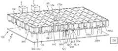
- FIG. 1shows a part of a module for a laboratory sample distribution system according to a first embodiment. It can be noted that typical parts of such a module such as a transport plane or a supporting structure are not shown in FIG. 1 .
- a plurality of electro-magnetic actuators 120 that can comprise electro-magnetic coilscan be arranged in a configuration such that a field of positions can be defined in a chequered manner. In each second line of positions, each second position can be left blank.
- Each electro-magnetic actuator 120can comprise a ferromagnetic core 125 .
- the ferromagnetic core 125can increase a magnetic field generated by a respective electro-magnetic coil of the electro-magnetic actuator 120 .
- a respective magnetic coupling element 126can be arranged.
- the magnetic coupling elements 126can increase magnetic coupling between respective pairs of ferromagnetic cores 125 .
- the electro-magnetic actuators 120can drive sample container carriers on a transport plane (not shown) that can typically be positioned above the electro-magnetic actuators 120 .
- a transport planenot shown
- energy efficiency of the modulecan be enhanced because the respective cores 125 of neighboring electro-magnetic actuators 120 can be magnetically coupled.
- the ferromagnetic cores 125 and the magnetic coupling elements 126 that can be arranged along a line extending from the front side to the rear side as shown in FIG. 1can be embodied as respective first ferromagnetic bars 10 .
- the ferromagnetic cores 125 and the magnetic coupling elements 126 arranged in lines perpendicular to that direction, i.e., from the left to the right side in FIG. 1 , with the exception of ferromagnetic cores 125 already belonging to the first ferromagnetic bars 10can be embodied as respective second ferromagnetic bars 20 .
- the ferromagnetic bars 10 , 20can each be embodied out of a plurality of transformer sheets that can be electrically isolated to each other. By this configuration, eddy currents can be prevented.
- the embodiment of the ferromagnetic cores 125 and the magnetic coupling elements 126 as respective ferromagnetic bars 10 , 20can provide for a good magnetic coupling because there is no gap and even no material junction between cores 125 and magnetic coupling elements 126 within one module.
- the ferromagnetic bars 10 , 20can each comprise a contact surface 127 as magnetic coupling enhancer.
- the contact surfaces 127can be positioned at the respective lower or bottom sides of the ferromagnetic bars 10 , 20 . They can be used in order to abut magnetic coupling rods for increased magnetic coupling to neighboring modules. It will be explained further below with reference to FIG. 5 how this can be accomplished.
- FIG. 2 ashows a schematic cross-sectional view of the first ferromagnetic bar 10 .
- FIG. 2 bshows a schematic cross-sectional view of the second ferromagnetic bar 20 . It can be noted that both FIG. 2 a and FIG. 2 b depict only parts of a respective ferromagnetic bar 10 , 20 , wherein the ferromagnetic bars 10 , 20 as shown in FIG. 1 are considerably longer.
- the first ferromagnetic bar 10 as shown in FIG. 2 acan have ferromagnetic cores 125 extending upward.
- the cores 125can have a certain distance that can be equal between each two pairs of cores 125 .
- Between each two cores 125there can be arranged a magnetic coupling element 126 .
- a recess 15can be formed below each second core 125 .
- the recesses 15can be arranged at the lower side of the first ferromagnetic bar 10 .
- the second ferromagnetic bar 20can also have ferromagnetic cores 125 , which can, however, be arranged with twice the distance of the ferromagnetic cores 125 of the first ferromagnetic bar 10 as shown in FIG. 2 a .
- the second ferromagnetic bar 20can have recesses 25 formed at its upper side at each second position where the first ferromagnetic bar 10 can have a core 125 .
- the recesses 25 of the second ferromagnetic bar 20can interact with corresponding recesses 15 of the first ferromagnetic bars 10 such that the first ferromagnetic bars 10 and the second ferromagnetic bars 20 can be arranged as shown in FIG. 1 .
- first ferromagnetic bars 10can be arranged parallel to each other, that a plurality of second ferromagnetic bars 20 can be arranged parallel to each other, and that the first ferromagnetic bars 10 can be arranged perpendicular to the second ferromagnetic bars 20 .
- the recesses 15 , 25can allow for a simple assembly of the configuration as shown in FIG. 1 .
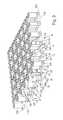
- FIG. 3shows a part of a module for a laboratory sample distribution system according to a second embodiment. This configuration is similar to the configuration according to the first embodiment as shown in FIG. 1 . For that reason, only the differences will be discussed in the following. Regarding the other items and features, reference is made to the description of FIG. 1 given above.
- the ferromagnetic bars 10 , 20can each comprise a magnetic coupling protrusion 128 between a ferromagnetic core 125 and an outer edge 160 , 170 , 180 , 190 (as depicted by the dashed line) of the module as magnetic coupling enhancers.
- the outer edges 160 , 170 , 180 , 190 of a modulecan be the edges determining a border line to another module.
- the outer edges 160 , 170 , 180 , 190can be determined by border lines of the transport plane (not shown) of a respective module.
- the magnetic coupling protrusions 128can be arranged in line with the magnetic coupling elements 126 between the cores 125 .
- the magnetic coupling protrusions 128can provide for an increased coupling to ferromagnetic cores 125 of neighboring modules.
- Each magnetic coupling protrusion 128can comprise a magnetic coupling surface 129 positioned at the outer edge ( 160 , 170 , 180 , 190 ) of the module and facing towards a surrounding of the module.
- the magnetic coupling surface 129can especially face to another magnetic coupling surface of a neighboring module such that a distance between the magnetic coupling surfaces 129 can be minimized. Thus, a gap between the magnetic coupling surfaces 129 can be minimized. Magnetic coupling between neighboring modules can thus be enhanced.
- magnetic couplingcan be enhanced without a need for additional magnetic coupling rods.
- FIG. 4shows a module 105 for a laboratory sample distribution system, the module 105 comprising a transport plane 110 that can be adapted such that sample container carriers can move on it. Furthermore, a plurality of magnetic sensors 130 can be distributed in the transport plane 110 . These magnetic sensors 130 can be used in order to sense respective positions of sample container carriers.
- FIG. 1Below the transport plane 110 , parts as shown in FIG. 1 can be arranged. Specifically, a plurality of electro-magnetic actuators 120 with respective ferromagnetic cores 125 can be arranged. Between the ferromagnetic cores 125 , respective magnetic coupling elements 126 can be arranged.
- the bars 10 , 20can be supported by a supporting structure 250 of the module 105 .
- the module 105can be retained with a lower or bottom side of the supporting structure 250 on pillars 310 of a retaining frame 300 of a laboratory sample distribution system.
- the bottom side of the supporting structurecan be opposite to the transport plane 110 .
- FIG. 5shows a laboratory automation system 5 comprising a first laboratory station 6 , a second laboratory station 7 and a laboratory sample distribution system 100 .
- the laboratory stations 6 , 7are shown as examples for a plurality of laboratory stations that are typically present in a laboratory automation system. They can, for example, be pre-analytical, analytical and/or post-analytical stations that perform tasks like analyzing a sample, centrifugation of a sample or the like.
- the laboratory sample distribution system 100can comprise a first module 105 and a second module 105 a .
- An outer edge 190 of the first module 105can touch an outer edge 170 a of the second module.
- the first module 105 and the second module 105 acan be concatenated such that they can form a common transport plane.
- the common transport planecan be formed by the transport plane 110 of the first module 105 and the transport plane 110 a of the second module 105 a .
- the first module 105 and the second module 105 acan be retained with bottom sides of their supporting structures 250 , 250 a on pillars 310 of a retaining frame 300 of the laboratory sample distribution system 100 .
- FIG. 4Regarding the further details of the modules 105 , 105 a , reference is made to FIG. 4 and the corresponding description given above.
- magnetic coupling rods 30can be positioned between respective ferromagnetic bars 20 , 20 a of different modules 105 , 105 a .
- the magnetic coupling rods 30each having a rectangular cross-section area, can be formed out of magnetically highly permeable material in order to provide for an effective coupling.
- Each magnetic coupling rod 30can abut two magnetic coupling surfaces 127 , 127 a of the different modules 105 , 105 a . Thus, there can be no remaining gap between neighboring magnetic rods 20 , 20 a .
- FIG. 6depicts the encircled part VI of FIG. 5 .
- This measurecan lead to a magnetic coupling between cores 125 , 125 a of different modules 105 , 105 a that can be approximately the same as the magnetic coupling between neighboring cores 125 of a module 105 that can be connected by a magnetic coupling element 126 .
- the magnetic coupling rods 30can be detachably fixed by a plurality of springs 200 on pillars 310 from the retaining frame 300 to the contact surfaces 127 , 127 a . This can allow for a simple detaching and attaching of the magnetic coupling rods 30 in the case one of the modules 105 , 105 a needs to be replaced.
- a typical laboratory sample distribution system 100can comprise more than two modules 105 , 105 a . Magnetic coupling between a plurality of modules 105 , 105 a can be enhanced just like described here with respect to two modules 105 , 105 a.
- the laboratory sample distribution system 100can further comprise a sample container carrier 140 .
- the sample container carrier 140can carry a sample container 145 .
- the sample container carrier 140can have a magnetically active device in the form of a permanent magnet that is not shown in FIG. 5 .
- the sample container carrier 140can move on the common transport plane.
- the sample container 145can be embodied as a tube made of transparent plastic material with an opening at its top side and can carry blood samples or other medical samples. By use of the sample container carrier 140 , sample containers 145 can be distributed between the laboratory stations 6 , 7 and other equipment.
- a typical laboratory sample distribution system 100can comprise more than one sample container carrier 140 .
- the sample container carrier 140 shown in FIG. 5is given as an exemplary illustration only.
- the laboratory sample distribution system 100can further comprise a control unit 150 that can drive the electro-magnetic actuators 120 , 120 a such that the sample container carriers 140 can move over the common transport plane on respective transport paths.
- FIG. 7shows in detail a part of a laboratory automation system comprising a laboratory sample distribution system with two modules 105 , 105 a , wherein the kind of module 105 , 105 a is shown in part in FIG. 3 .
- the configuration of FIG. 7can be similar to the configuration according to the first embodiment as shown in FIG. 6 . For that reason, only the differences will be discussed in the following.
- the ferromagnetic bars 20 , 20 acan each comprise a magnetic coupling protrusion 128 , 128 a .
- Each magnetic coupling protrusion 128 , 128 acan comprise a magnetic coupling surface 129 , 129 a and facing towards the other such that a distance between the magnetic coupling surfaces 129 can be minimized.
- a gap between the magnetic coupling surfaces 129can be minimized. Magnetic coupling between neighboring 105 , 105 a modules can be thus enhanced.
- each magnetic coupling surfacemay have a cross-section area larger than a cross-section area of the magnetic coupling elements 126 .
Landscapes
- General Health & Medical Sciences (AREA)
- Health & Medical Sciences (AREA)
- Life Sciences & Earth Sciences (AREA)
- Chemical & Material Sciences (AREA)
- Analytical Chemistry (AREA)
- Biochemistry (AREA)
- Physics & Mathematics (AREA)
- General Physics & Mathematics (AREA)
- Immunology (AREA)
- Pathology (AREA)
- Automatic Analysis And Handling Materials Therefor (AREA)
- Non-Mechanical Conveyors (AREA)
- Sampling And Sample Adjustment (AREA)
Abstract
Description
Claims (18)
Applications Claiming Priority (3)
| Application Number | Priority Date | Filing Date | Title |
|---|---|---|---|
| EP14187891 | 2014-10-07 | ||
| EP14187891.8 | 2014-10-07 | ||
| EP14187891.8AEP3006943B1 (en) | 2014-10-07 | 2014-10-07 | Module for a laboratory sample distribution system, laboratory sample distribution system and laboratory automation system |
Publications (2)
| Publication Number | Publication Date |
|---|---|
| US20160097786A1 US20160097786A1 (en) | 2016-04-07 |
| US9618525B2true US9618525B2 (en) | 2017-04-11 |
Family
ID=51659579
Family Applications (1)
| Application Number | Title | Priority Date | Filing Date |
|---|---|---|---|
| US14/865,822ActiveUS9618525B2 (en) | 2014-10-07 | 2015-09-25 | Module for a laboratory sample distribution system, laboratory sample distribution system and laboratory automation system |
Country Status (4)
| Country | Link |
|---|---|
| US (1) | US9618525B2 (en) |
| EP (1) | EP3006943B1 (en) |
| JP (1) | JP6080927B2 (en) |
| CN (1) | CN105600468B (en) |
Cited By (29)
| Publication number | Priority date | Publication date | Assignee | Title |
|---|---|---|---|---|
| US20170131309A1 (en)* | 2014-07-24 | 2017-05-11 | Roche Diagnostics Operations, Inc. | Laboratory sample distribution system and laboratory automation system |
| US10126317B2 (en) | 2011-11-04 | 2018-11-13 | Roche Diagnostics Operations, Inc. | Laboratory sample distribution system, laboratory system and method of operating |
| US20180340951A1 (en)* | 2016-02-26 | 2018-11-29 | Roche Diagnostics Operations, Inc. | Transport device having a tilted driving surface |
| US10160609B2 (en)* | 2015-10-13 | 2018-12-25 | Roche Diagnostics Operations, Inc. | Laboratory sample distribution system and laboratory automation system |
| US10197586B2 (en) | 2015-10-06 | 2019-02-05 | Roche Diagnostics Operations, Inc. | Method of determining a handover position and laboratory automation system |
| US10239708B2 (en) | 2014-09-09 | 2019-03-26 | Roche Diagnostics Operations, Inc. | Laboratory sample distribution system and laboratory automation system |
| US10416183B2 (en) | 2016-12-01 | 2019-09-17 | Roche Diagnostics Operations, Inc. | Laboratory sample distribution system and laboratory automation system |
| US10436808B2 (en) | 2016-12-29 | 2019-10-08 | Roche Diagnostics Operations, Inc. | Laboratory sample distribution system and laboratory automation system |
| US10495657B2 (en) | 2017-01-31 | 2019-12-03 | Roche Diagnostics Operations, Inc. | Laboratory sample distribution system and laboratory automation system |
| US10509049B2 (en) | 2014-09-15 | 2019-12-17 | Roche Diagnostics Operations, Inc. | Method of operating a laboratory sample distribution system, laboratory sample distribution system and laboratory automation system |
| US10520520B2 (en) | 2016-02-26 | 2019-12-31 | Roche Diagnostics Operations, Inc. | Transport device with base plate modules |
| US10564170B2 (en) | 2015-07-22 | 2020-02-18 | Roche Diagnostics Operations, Inc. | Sample container carrier, laboratory sample distribution system and laboratory automation system |
| US10578632B2 (en) | 2016-02-26 | 2020-03-03 | Roche Diagnostics Operations, Inc. | Transport device unit for a laboratory sample distribution system |
| US10962557B2 (en) | 2017-07-13 | 2021-03-30 | Roche Diagnostics Operations, Inc. | Method of operating a laboratory sample distribution system, laboratory sample distribution system and laboratory automation system |
| US10989725B2 (en) | 2017-06-02 | 2021-04-27 | Roche Diagnostics Operations, Inc. | Method of operating a laboratory sample distribution system, laboratory sample distribution system, and laboratory automation system |
| US10989726B2 (en) | 2016-06-09 | 2021-04-27 | Roche Diagnostics Operations, Inc. | Laboratory sample distribution system and method of operating a laboratory sample distribution system |
| US10996233B2 (en) | 2016-06-03 | 2021-05-04 | Roche Diagnostics Operations, Inc. | Laboratory sample distribution system and laboratory automation system |
| US11092613B2 (en) | 2015-05-22 | 2021-08-17 | Roche Diagnostics Operations, Inc. | Method of operating a laboratory sample distribution system, laboratory sample distribution system and laboratory automation system |
| US11110463B2 (en) | 2017-09-13 | 2021-09-07 | Roche Diagnostics Operations, Inc. | Sample container carrier, laboratory sample distribution system and laboratory automation system |
| US11112421B2 (en) | 2016-08-04 | 2021-09-07 | Roche Diagnostics Operations, Inc. | Laboratory sample distribution system and laboratory automation system |
| US11110464B2 (en) | 2017-09-13 | 2021-09-07 | Roche Diagnostics Operations, Inc. | Sample container carrier, laboratory sample distribution system and laboratory automation system |
| US11226348B2 (en) | 2015-07-02 | 2022-01-18 | Roche Diagnostics Operations, Inc. | Storage module, method of operating a laboratory automation system and laboratory automation system |
| US20220274792A1 (en)* | 2019-10-01 | 2022-09-01 | Hitachi High-Tech Corporation | Conveying device and analysis system |
| US11709171B2 (en) | 2018-03-16 | 2023-07-25 | Roche Diagnostics Operations, Inc. | Laboratory system, laboratory sample distribution system and laboratory automation system |
| US11747356B2 (en) | 2020-12-21 | 2023-09-05 | Roche Diagnostics Operations, Inc. | Support element for a modular transport plane, modular transport plane, and laboratory distribution system |
| US11971420B2 (en) | 2018-03-07 | 2024-04-30 | Roche Diagnostics Operations, Inc. | Method of operating a laboratory sample distribution system, laboratory sample distribution system and laboratory automation system |
| US12000850B2 (en) | 2020-06-19 | 2024-06-04 | Roche Diagnostics Operations, Inc. | Laboratory sample distribution system and corresponding method of operation |
| US12000851B2 (en) | 2020-07-15 | 2024-06-04 | Roche Diagnostics Operations, Inc. | Laboratory sample distribution system and method for operating the same |
| US12429491B2 (en) | 2020-11-23 | 2025-09-30 | Roche Diagnostics Operations, Inc. | Laboratory sample distribution system and laboratory automation system |
Families Citing this family (39)
| Publication number | Priority date | Publication date | Assignee | Title |
|---|---|---|---|---|
| DE102010028769A1 (en) | 2010-05-07 | 2011-11-10 | Pvt Probenverteiltechnik Gmbh | System for transporting containers between different stations and container carriers |
| EP2589966A1 (en) | 2011-11-04 | 2013-05-08 | Roche Diagnostics GmbH | Laboratory sample distribution system and corresponding method of operation |
| EP2589967A1 (en) | 2011-11-04 | 2013-05-08 | Roche Diagnostics GmbH | Laboratory sample distribution system and corresponding method of operation |
| DE102014202843B3 (en) | 2014-02-17 | 2014-11-06 | Roche Pvt Gmbh | Transport device, sample distribution system and laboratory automation system |
| DE102014202838B3 (en) | 2014-02-17 | 2014-11-06 | Roche Pvt Gmbh | Transport device, sample distribution system and laboratory automation system |
| EP2927167B1 (en) | 2014-03-31 | 2018-04-18 | F. Hoffmann-La Roche AG | Dispatch device, sample distribution system and laboratory automation system |
| EP2927163B1 (en) | 2014-03-31 | 2018-02-28 | Roche Diagnostics GmbH | Vertical conveyor, sample distribution system and laboratory automation system |
| EP2927695B1 (en) | 2014-03-31 | 2018-08-22 | Roche Diagniostics GmbH | Sample distribution system and laboratory automation system |
| EP2927625A1 (en) | 2014-03-31 | 2015-10-07 | Roche Diagniostics GmbH | Sample distribution system and laboratory automation system |
| EP2927168A1 (en) | 2014-03-31 | 2015-10-07 | Roche Diagniostics GmbH | Transport device, sample distribution system and laboratory automation system |
| EP2957914B1 (en) | 2014-06-17 | 2018-01-03 | Roche Diagnostics GmbH | Laboratory sample distribution system and laboratory automation system |
| EP2995960B1 (en) | 2014-09-09 | 2020-07-15 | Roche Diagniostics GmbH | Laboratory sample distribution system and method for calibrating magnetic sensors |
| US9952242B2 (en) | 2014-09-12 | 2018-04-24 | Roche Diagnostics Operations, Inc. | Laboratory sample distribution system and laboratory automation system |
| EP3016116A1 (en) | 2014-11-03 | 2016-05-04 | Roche Diagniostics GmbH | Printed circuit board arrangement, coil for a laboratory sample distribution system, laboratory sample distribution system and laboratory automation system |
| EP3250488B1 (en)* | 2015-01-30 | 2022-04-06 | Laitram, L.L.C. | Lim-driven roller transfer apparatus |
| EP3070479B1 (en) | 2015-03-16 | 2019-07-03 | Roche Diagniostics GmbH | Transport carrier, laboratory cargo distribution system and laboratory automation system |
| EP3073270B1 (en) | 2015-03-23 | 2019-05-29 | Roche Diagniostics GmbH | Laboratory sample distribution system and laboratory automation system |
| EP3096145B1 (en) | 2015-05-22 | 2019-09-04 | Roche Diagniostics GmbH | Method of operating a laboratory automation system and laboratory automation system |
| EP3095739A1 (en) | 2015-05-22 | 2016-11-23 | Roche Diagniostics GmbH | Method of operating a laboratory sample distribution system, laboratory sample distribution system and laboratory automation system |
| EP3139175B1 (en) | 2015-09-01 | 2021-12-15 | Roche Diagnostics GmbH | Laboratory cargo distribution system, laboratory automation system and method of operating a laboratory cargo distribution system |
| EP3153867B1 (en) | 2015-10-06 | 2018-11-14 | Roche Diagniostics GmbH | Method of configuring a laboratory automation system, laboratory sample distribution system and laboratory automation system |
| EP3156353B1 (en) | 2015-10-14 | 2019-04-03 | Roche Diagniostics GmbH | Method of rotating a sample container carrier, laboratory sample distribution system and laboratory automation system |
| CN113751095B (en) | 2015-12-11 | 2024-01-09 | 巴布森诊断公司 | Sample container and method for separating serum or plasma from whole blood |
| JP2017188867A (en) | 2015-12-24 | 2017-10-12 | 日本電産エレシス株式会社 | Waveguide device, slot antenna, and radar with the slot antenna, radar system, and wireless communications system |
| EP3260867A1 (en) | 2016-06-21 | 2017-12-27 | Roche Diagnostics GmbH | Method of setting a handover position and laboratory automation system |
| CN110291377B (en)* | 2016-11-14 | 2023-09-05 | 巴布森诊断公司 | Sample preparation device |
| EP3357842B1 (en) | 2017-02-03 | 2022-03-23 | Roche Diagnostics GmbH | Laboratory automation system |
| EP3382397A1 (en)* | 2017-03-30 | 2018-10-03 | Roche Diagnostics GmbH | Laboratory sample distribution system and laboratory automation system |
| JP2020142912A (en)* | 2019-03-08 | 2020-09-10 | 株式会社日立ハイテク | Conveying device, specimen analysis system including the same, and specimen pretreatment device |
| JP7300281B2 (en)* | 2019-03-08 | 2023-06-29 | 株式会社日立ハイテク | Transporting device, sample analysis system provided with same, sample pretreatment device, and transporting method for transported object |
| JP7319096B2 (en)* | 2019-06-12 | 2023-08-01 | 株式会社日立ハイテク | Conveyor |
| JP7304831B2 (en) | 2020-02-18 | 2023-07-07 | 株式会社日立ハイテク | Sample analysis system having transport device and transport device |
| EP3974839B1 (en) | 2020-09-23 | 2024-03-27 | Roche Diagnostics GmbH | A method for detecting and reporting an operation error in an in-vitro diagnostic system, a transport device for a laboratory sample distribution system, and a laboratory sample distribution system |
| JP7628801B2 (en)* | 2020-10-27 | 2025-02-12 | 株式会社日立ハイテク | Group coffees Be video golddent Seriesnic risk was promise expected ... Complexros Be video Ti Anyvent video Series Ti Any included Play potential Gold section Inter known Co member video black Series Ti Anyvent video risk Complexs video risk Complexs video risk Complexs video risk Complexs video risk Complexs video risk Co Lightventsnic risk member video black Series Intertractduct surface section Inter Works Series Ti Any risk section Anniversary Vi Works Works Works Series Ti Any confess Bes Series Ti |
| EP4016084A1 (en)* | 2020-12-21 | 2022-06-22 | Roche Diagnostics GmbH | Modular transport plane and laboratory distribution system |
| US12050052B1 (en) | 2021-08-06 | 2024-07-30 | Babson Diagnostics, Inc. | Refrigerated carrier device for biological samples |
| JP7692765B2 (en)* | 2021-08-26 | 2025-06-16 | 株式会社日立ハイテク | TRANSPORTATION DEVICE, SAMPLE ANALYSIS SYSTEM INCLUDING TRANSPORTATION DEVICE, AND SAMPLE PRE-TREATMENT DEVICE INCLUDING TRANSPORTATION DEVICE |
| EP4505185A1 (en) | 2022-04-06 | 2025-02-12 | Babson Diagnostics, Inc. | Automated centrifuge loader |
| EP4530637A1 (en)* | 2023-09-29 | 2025-04-02 | Roche Diagnostics GmbH | Transport device and laboratory sample distribution system |
Citations (192)
| Publication number | Priority date | Publication date | Assignee | Title |
|---|---|---|---|---|
| US3273727A (en) | 1966-09-20 | Load handling apparatus | ||
| US3653485A (en) | 1971-03-05 | 1972-04-04 | Transportation Technology | An air bearing conveyor |
| US3901656A (en) | 1972-08-24 | 1975-08-26 | American Monitor Corp | Apparatus and method for preparing and presenting serum chemistries for analyzation |
| US4150666A (en) | 1977-06-27 | 1979-04-24 | Sherwood Medical Industries Inc. | Tube holder for blood collection tubes of different sizes |
| SU685591A1 (en) | 1977-08-01 | 1979-09-15 | Украинский Государственный Институт По Проектированию Металлургических Заводов | Tube mail despatch carrier |
| JPS56147209A (en) | 1980-04-16 | 1981-11-16 | Hitachi Kiden Kogyo Ltd | Automatic steering method for unattended carrying vehicle |
| US4395164A (en) | 1977-05-20 | 1983-07-26 | Krupp Polysius Ag | Pneumatic tube installation for posting samples of material |
| US4544068A (en) | 1983-08-16 | 1985-10-01 | The United States Of America As Represented By The Administrator Of The National Aeronautics And Space Administration | Laboratory glassware rack for seismic safety |
| JPS60223481A (en) | 1984-04-18 | 1985-11-07 | Nippon Telegr & Teleph Corp <Ntt> | Magnetically levitating guide device |
| GB2165515A (en) | 1984-10-12 | 1986-04-16 | Mitsubishi Chem Ind | Conveyor |
| JPS6181323A (en) | 1984-09-27 | 1986-04-24 | Mitsubishi Chem Ind Ltd | Aligned object moving device |
| JPS6194925A (en) | 1984-10-12 | 1986-05-13 | Mitsubishi Chem Ind Ltd | Transport equipment |
| JPS61174031A (en) | 1985-01-29 | 1986-08-05 | Youichi Oohira | Conveying device aimed at divergence, using linear induction motor type x-y actuator |
| JPS61217434A (en) | 1985-03-20 | 1986-09-27 | Mitsubishi Chem Ind Ltd | Conveying device |
| JPS62100161A (en) | 1985-10-23 | 1987-05-09 | Shin Etsu Chem Co Ltd | Planar motor |
| JPS6331918A (en) | 1986-07-16 | 1988-02-10 | フエコ・エンジニア−ド・システムズ・インコ−ポレ−テツド | Rotatable and retractable vessel holder and conveyor thereof |
| JPS6348169A (en) | 1986-08-14 | 1988-02-29 | Fuji Elelctrochem Co Ltd | piezoelectric actuator |
| JPS6382433U (en) | 1986-11-15 | 1988-05-30 | ||
| US4771237A (en) | 1986-02-19 | 1988-09-13 | Panametrics | Method and apparatus for calibrating a displacement probe using a polynomial equation to generate a displacement look-up table |
| JPS63290101A (en) | 1987-05-22 | 1988-11-28 | Toshiba Corp | Linear motor type conveyor system |
| JPH01148966A (en) | 1987-12-04 | 1989-06-12 | Hitachi Kiden Kogyo Ltd | Sample transport device |
| JPH01266860A (en) | 1988-04-19 | 1989-10-24 | Yukitaka Furukawa | Test tube holding tool permitting cooling of the test tube |
| JPH0287903A (en) | 1988-09-21 | 1990-03-28 | Daifuku Co Ltd | Carrying facility utilizing linear motor |
| DE3909786A1 (en) | 1989-03-24 | 1990-09-27 | Schlafhorst & Co W | Apparatus for transporting cops and tubes between planes changing in the course of transport |
| JPH03192013A (en) | 1989-12-21 | 1991-08-21 | Toshiba Corp | display device |
| US5120506A (en) | 1988-12-16 | 1992-06-09 | Fuji Photo Film Co., Ltd. | Chemical analyzer |
| JPH0569350A (en) | 1991-09-11 | 1993-03-23 | Toshiba Corp | Orbital robotic equipment maintenance equipment |
| JPH05180847A (en) | 1991-12-31 | 1993-07-23 | Hiranuma Sangyo Kk | Automatic cycler for analyzer |
| JPH0626808A (en) | 1992-07-09 | 1994-02-04 | Ebara Corp | Sensor target |
| US5295570A (en) | 1989-06-10 | 1994-03-22 | W. Schlafhorst Ag & Co. | Magnetic guiding assembly for yarn packages transported on a textile machine |
| US5309049A (en) | 1991-08-05 | 1994-05-03 | Mitsubishi Jukogyo Kabushiki Kaisha | Alternating current magnetic levitation transport system |
| JPH06148198A (en) | 1992-11-05 | 1994-05-27 | Hitachi Ltd | Contamination preventing device for analyzing equipment |
| JPH06156730A (en) | 1992-11-13 | 1994-06-03 | Ebara Corp | Conveying device |
| EP0601213A1 (en) | 1992-10-29 | 1994-06-15 | Hamilton Bonaduz AG | Transportdevice for goods |
| JPH06211306A (en) | 1993-01-19 | 1994-08-02 | Ebara Corp | Substrate storage device |
| JPH07228345A (en) | 1994-02-14 | 1995-08-29 | Ebara Corp | Tunnel conveyer |
| JPH07236838A (en) | 1994-02-28 | 1995-09-12 | Teruaki Ito | Method for centrifugal separation treatment of specimen and apparatus therefor |
| US5523131A (en) | 1994-11-01 | 1996-06-04 | Innovative Premiums Inc. | Self-propelled table novelty device |
| US5530345A (en) | 1992-09-30 | 1996-06-25 | Sgs-Thomson Microelectronics S.R.L. | An integrated hall•effect apparatus for detecting the position of a magnetic element |
| WO1996036437A1 (en) | 1995-05-15 | 1996-11-21 | Smithkline Beecham Corporation | Vial holder |
| EP0775650A1 (en) | 1995-11-24 | 1997-05-28 | André Dr. von Froreich | Conveyor system, especially for material carriers to be used in medical laboratories |
| US5636548A (en) | 1994-05-16 | 1997-06-10 | Tesoro Alaska Petroleum Company | Analog hall-effect liquid level detector and method |
| US5641054A (en) | 1992-07-07 | 1997-06-24 | Ebara Corporation | Magnetic levitation conveyor apparatus |
| US5651941A (en) | 1992-06-29 | 1997-07-29 | Dade International Inc. | Sample tube carrier |
| US5720377A (en) | 1995-07-14 | 1998-02-24 | Chiron Diagnostics Corporation | Magnetic conveyor system |
| US5735387A (en) | 1995-07-14 | 1998-04-07 | Chiron Diagnostics Corporation | Specimen rack handling system |
| US5788929A (en) | 1996-03-12 | 1998-08-04 | Nesti; Edmund D. | Sample temperature protection rack |
| EP0896936A1 (en) | 1997-08-11 | 1999-02-17 | Murata Kikai Kabushiki Kaisha | Carrier transport device |
| JPH1183865A (en) | 1997-09-11 | 1999-03-26 | Hitachi Ltd | Sample transport system |
| EP0916406A2 (en) | 1997-11-13 | 1999-05-19 | Bayer Corporation | Puck for a sample tube |
| JPH11264828A (en) | 1998-03-19 | 1999-09-28 | Hitachi Ltd | Sample transport system |
| JPH11304812A (en) | 1998-04-20 | 1999-11-05 | Hitachi Ltd | Sample processing system |
| JPH11326336A (en) | 1998-05-19 | 1999-11-26 | Aloka Co Ltd | Label reading apparatus |
| JP2000105246A (en) | 1998-09-29 | 2000-04-11 | Hitachi Ltd | Automatic analyzer |
| JP2000105243A (en) | 1998-09-29 | 2000-04-11 | Hitachi Ltd | Rack transport device |
| US6062398A (en) | 1999-07-21 | 2000-05-16 | Thalmayr; Hermann | Insert for holding test tubes in a conveyor capsule of a pneumatic tube conveyor system |
| JP3112393B2 (en) | 1995-05-25 | 2000-11-27 | シャープ株式会社 | Color display |
| JP2001124786A (en) | 1999-10-29 | 2001-05-11 | Hitachi Eng Co Ltd | Sample sorting device |
| US6255614B1 (en) | 1999-05-14 | 2001-07-03 | Sysmex Corporation | Specimen-container transfer apparatus |
| US6260360B1 (en) | 1997-11-24 | 2001-07-17 | Isosafe Limited | Container |
| EP1122194A1 (en) | 2000-02-01 | 2001-08-08 | Johnson & Johnson Vision Care, Inc. | Apparatus and method for automated warehousing |
| US6279728B1 (en) | 1998-07-20 | 2001-08-28 | Norbert G Jung | Electro-magnetic conveyor |
| JP2001240245A (en) | 2000-03-01 | 2001-09-04 | Auto Cs Engineering Co Ltd | Conveying system and conveying device by compressed air |
| US6293750B1 (en) | 1998-07-14 | 2001-09-25 | Bayer Corporation | Robotics for transporting containers and objects within an automated analytical instrument and service tool for servicing robotics |
| US20020009391A1 (en) | 1999-05-03 | 2002-01-24 | Ljl Biosystems, Inc. | Integrated sample-processing system |
| US6429016B1 (en) | 1999-10-01 | 2002-08-06 | Isis Pharmaceuticals, Inc. | System and method for sample positioning in a robotic system |
| US6444171B1 (en) | 1998-07-31 | 2002-09-03 | Hitachi, Ltd. | Sample processing system |
| US20030089581A1 (en) | 2001-11-14 | 2003-05-15 | Thompson David R. | Bi-directional magnetic sample rack conveying system |
| US20030092185A1 (en) | 2001-03-16 | 2003-05-15 | Humayun Qureshi | Method and system for automated immunochemistry analysis |
| US20040050836A1 (en) | 2000-09-29 | 2004-03-18 | Nesbitt Geoffrey John | Assembly of an integrated vessel transporter and at least one reaction vessel and integrated vessel transporter for transporting a chemical substance |
| US20040084531A1 (en) | 2002-11-01 | 2004-05-06 | Teruaki Itoh | Bar code generating apparatus |
| JP2005001055A (en) | 2003-06-11 | 2005-01-06 | Fanuc Ltd | Robot device |
| US20050061622A1 (en) | 2001-10-29 | 2005-03-24 | Martin Kevin Joseph | Conveying apparatus |
| EP1524525A1 (en) | 2003-10-14 | 2005-04-20 | Ortho-Clinical Diagnostics, Inc. | Moving evaporation control cover |
| US20050109580A1 (en) | 2003-11-26 | 2005-05-26 | Cynthia Thompson | Conveyor belt cleaning apparatus |
| US20050196320A1 (en) | 2004-03-05 | 2005-09-08 | Beckman Coulter, Inc. | Specimen-transport module for a multi-instrument clinical workcell |
| US20050194333A1 (en) | 2004-03-05 | 2005-09-08 | Beckman Coulter, Inc. | Specimen-container rack for automated clinical instrument |
| JP2005249740A (en) | 2004-03-08 | 2005-09-15 | Olympus Corp | Sample rack conveyer, and sample rack conveying method |
| US20050226770A1 (en) | 2002-09-26 | 2005-10-13 | Biopath Automation, L.L.C. | Apparatus and methods for automated handling and embedding of tissue samples |
| US20050242963A1 (en) | 2004-03-19 | 2005-11-03 | Applera Corporation | Sample carrier device incorporating radio frequency identification, and method |
| US20050247790A1 (en) | 2004-04-26 | 2005-11-10 | Ids Co., Ltd. | Reading apparatus for bar code on a test tube |
| US20050260101A1 (en) | 2000-10-10 | 2005-11-24 | Matthias Nauck | Closure element and closure system |
| US20050271555A1 (en) | 2004-04-07 | 2005-12-08 | Ids Co., Ltd. | Self-running sample holder and system having self-running sample holders |
| US20060000296A1 (en) | 2004-07-02 | 2006-01-05 | Salter Jason P | Synchronization of sample and data collection |
| US20060047303A1 (en) | 2004-07-28 | 2006-03-02 | Ethicon Endo-Surgery, Inc. | Electroactive polymer-based actuation mechanism for grasper |
| US7028831B2 (en) | 2004-03-05 | 2006-04-18 | Beckman Coulter, Inc. | Magnetic specimen-transport system for automated clinical instrument |
| JP2006106008A (en) | 2005-12-20 | 2006-04-20 | Jsk Kk | Capacitance type detector |
| US7078082B2 (en) | 2004-01-15 | 2006-07-18 | Sonoco Development, Inc. | Dual-functioning mechanism for startup during winding of web material and for splicing during unwinding |
| US7122158B2 (en) | 2002-02-28 | 2006-10-17 | Teruaki Itoh | Test tube holder |
| WO2007024540A1 (en) | 2005-08-25 | 2007-03-01 | Coldtrack, Llc | Hierarchical sample coding and storage system |
| US20070116611A1 (en) | 2005-11-14 | 2007-05-24 | Demarco Nicholas | Fraction collection system |
| US20070210090A1 (en) | 2004-01-08 | 2007-09-13 | Bernhard Sixt | Transport Container For Keeping Frozen Material Chilled |
| US20070248496A1 (en) | 2006-04-25 | 2007-10-25 | Ecocap's S.R.L. | Resealer of test tubes for clinical analyses fed from ready-to-use containers of sealing tape |
| US20070276558A1 (en) | 2004-03-27 | 2007-11-29 | Kyeong-Keun Kim | Navigation system for position self control robot and floor materials for providing absolute coordinates used thereof |
| JP2007309675A (en) | 2006-05-16 | 2007-11-29 | Olympus Corp | Sample rack supply-and-recovery system |
| JP2007314262A (en) | 2006-05-23 | 2007-12-06 | Daifuku Co Ltd | Article processing equipment |
| JP2007322289A (en) | 2006-06-01 | 2007-12-13 | Olympus Corp | Conveyer |
| US20080012511A1 (en) | 2004-07-15 | 2008-01-17 | Nikon Corporation | Planar Motor Device, Stage Device, Exposure Device and Device Manufacturing Method |
| US7326565B2 (en) | 2002-11-19 | 2008-02-05 | Sanyo Electric Co., Ltd. | Storage apparatus |
| US20080029368A1 (en) | 2004-12-20 | 2008-02-07 | Kyushu Institute Of Technology | Non-Contact Conveying Device Using Superconducting Magnetic Levitation |
| US20080056328A1 (en) | 2005-08-19 | 2008-03-06 | F.O.B. Instruments, Ltd. | Apparatus and Method for Determining the Amount of Time until a Desired Temperature is Reached |
| CN201045617Y (en) | 2006-04-21 | 2008-04-09 | 北京赛科希德科技发展有限公司 | Test cup continuous conveyer for full-automatic cruor measurement |
| US20080131961A1 (en) | 2003-06-04 | 2008-06-05 | Genial Genetic Solutions Limited | Biological Apparatus |
| US7428957B2 (en) | 2003-08-26 | 2008-09-30 | Ssi Schaefer Peen Gmbh | Order picking station and order picking method |
| WO2008133708A1 (en) | 2007-05-01 | 2008-11-06 | Siemens Healthcare Diagnostics Inc. | Programmable random access sample handler for use within an automated laboratory system |
| US20080286162A1 (en) | 2007-05-16 | 2008-11-20 | Onizawa Kuniaki | Sample handling system |
| WO2009002358A1 (en) | 2007-06-26 | 2008-12-31 | Siemens Healthcare Diagnostics Inc. | Mobile sample storage and retrieval unit for a laboratory automated sample handling worksystem |
| US20090004732A1 (en) | 2007-06-06 | 2009-01-01 | Labarre Paul Donald | Chemical Temperature Control |
| US20090022625A1 (en) | 2007-07-19 | 2009-01-22 | Samsung Electronics Co., Ltd. | Biochemical analyzer and method of controlling internal temperature of the biochemical analyzer |
| US20090081771A1 (en) | 2003-06-06 | 2009-03-26 | Micronics, Inc. | System and method for heating, cooling and heat cycling on microfluidic device |
| JP2009062188A (en) | 2007-09-10 | 2009-03-26 | Tsubakimoto Chain Co | Sorting device using linear guide motor type x-y actuator |
| US20090128139A1 (en) | 2007-11-20 | 2009-05-21 | Drenth Joseph B | Magnet position locator |
| US20090142844A1 (en) | 2005-07-08 | 2009-06-04 | Horiba Abx Sas | Automatic Method of Preparing Samples of Total Blood For Analysis, and an Automatic Device For Implementing the Method |
| JP2009145188A (en) | 2007-12-13 | 2009-07-02 | Horiba Ltd | Test tube holder and sample suction apparatus |
| EP2119643A1 (en) | 2008-05-16 | 2009-11-18 | TGW Mechanics GmbH | Method and storage system for consolidating of shipping units |
| JP2009300402A (en) | 2008-06-17 | 2009-12-24 | Olympus Corp | Analyzer and analytical method |
| US20090322486A1 (en) | 2007-03-15 | 2009-12-31 | Joint Analytical Systems Gmbh | RFID Storage Systems |
| US20100000250A1 (en) | 2006-07-13 | 2010-01-07 | Bernhard Sixt | Transport container for maintaining the temperature of frozen goods |
| EP2148117A1 (en) | 2007-06-19 | 2010-01-27 | Kitz Corporation | Shaft sealing device, and valve structure using the device |
| WO2010042722A1 (en) | 2008-10-10 | 2010-04-15 | Quest Diagnostics Investments Incorporated | System and method for sorting specimen |
| US20100152895A1 (en) | 2008-12-05 | 2010-06-17 | Zhengshan Dai | Shock freezer and system for preparing samples for analysis using the same |
| US20100175943A1 (en) | 2007-06-02 | 2010-07-15 | Bergmann Lars B | Storage or Conveying System |
| US20100186618A1 (en) | 2009-01-23 | 2010-07-29 | Magnemotion, Inc. | Transport system powered by short block linear synchronous motors |
| WO2010087303A1 (en) | 2009-01-27 | 2010-08-05 | 株式会社日立ハイテクノロジーズ | Automated analyzer and automatic analysis method |
| US20100255529A1 (en) | 2007-12-07 | 2010-10-07 | Francesco Cocola | Device and method for microbiological analysis of biological samples |
| WO2010129715A1 (en) | 2009-05-05 | 2010-11-11 | Cypress Semiconductor Corporation | Spill-over detection method and system |
| US20100300831A1 (en) | 2007-11-30 | 2010-12-02 | Gianandrea Pedrazzini | System for automatically identifying, conveying and addressing biological material specimens |
| US20100312379A1 (en) | 2007-11-30 | 2010-12-09 | Gianandrea Pedrazzini | Automatic apparatus for loading and unloading biological material test tubes in a pneumatic mail system |
| US7858033B2 (en) | 2006-09-20 | 2010-12-28 | Ids Co., Ltd. | Specimen preprocessing/transport apparatus |
| US7875254B2 (en) | 2006-07-10 | 2011-01-25 | Exxonmobil Chemical Patents Inc. | Internal loop reactor and Oxo process using same |
| US20110050213A1 (en) | 2008-01-16 | 2011-03-03 | Kabushiki Kaisha Bridgestone | Belt monitoring system |
| US7939484B1 (en) | 2009-10-27 | 2011-05-10 | Clariant International, Ltd. | Method for reducing the adhesion forces between hard surfaces and subsequently occurring soil |
| EP2327646A1 (en) | 2009-11-26 | 2011-06-01 | GLP systems GmbH | Switch in a branch of a transport path for laboratory samples in an analytical laboratory |
| CN102109530A (en) | 2009-12-28 | 2011-06-29 | 希森美康株式会社 | Sample processing apparatus and sample rack transport method |
| US20110172128A1 (en) | 2008-09-12 | 2011-07-14 | Anthony Davies | Multi-well device |
| US20110186406A1 (en) | 2010-01-29 | 2011-08-04 | Ecolab Usa Inc. | Clean conveyor sensing system |
| WO2011138448A1 (en) | 2010-05-07 | 2011-11-10 | Pvt Probenverteiltechnik Gmbh | System for transporting containers between different stations, and the container carrier |
| US20110287447A1 (en) | 2009-05-12 | 2011-11-24 | Life Technologies Corporation | Apparatus for and method of automated processing of biological samples |
| US20120037696A1 (en) | 2010-08-13 | 2012-02-16 | Lear Sirous Lavi | Transfer, Link, Bind, Specimen Tube Barcode Information To RFID Specimen Transport Puck In A Continuous Moving Binding Process Method |
| EP2447701A2 (en) | 2010-10-28 | 2012-05-02 | Sysmex Corporation | Sample processing system and method of processing sample |
| US20120178170A1 (en) | 2009-07-16 | 2012-07-12 | Peter Van Praet | Sample container intelligent rack and loading method |
| US20120211645A1 (en) | 2011-02-23 | 2012-08-23 | JLT & Associates, Inc. | Conveyor sterilization |
| EP2502675A1 (en) | 2011-03-25 | 2012-09-26 | Symbion Medical Systems Sàrl | Container holder and container carrier |
| US20120275885A1 (en) | 2011-04-29 | 2012-11-01 | Frederic Furrer | Method for operating an automated sample workcell |
| US20120282683A1 (en) | 2010-01-21 | 2012-11-08 | Kazunori Mototsu | Sample analysis device |
| WO2012158541A1 (en) | 2011-05-13 | 2012-11-22 | Beckman Coulter, Inc. | System and method including laboratory product transport element |
| WO2012158520A1 (en) | 2011-05-13 | 2012-11-22 | Beckman Coulter, Inc. | Laboratory product transport element and path arrangement |
| US20120295358A1 (en) | 2010-01-21 | 2012-11-22 | Siemens Healthcare Diagnostics Inc. | Magnetic Conveyor Systems, Apparatus and Methods Including Moveable Magnet |
| US20120310401A1 (en) | 2011-06-03 | 2012-12-06 | Rushabh Instruments, Inc. | Rotary tissue processor with configurable stations |
| WO2012170636A1 (en) | 2011-06-07 | 2012-12-13 | Magnemotion, Inc. | Versatile control of a linear synchronous motor propulsion system |
| US20130126302A1 (en) | 2011-11-07 | 2013-05-23 | Beckman Coulter, Inc. | Magnetic damping for specimen transport system |
| US20130153677A1 (en) | 2010-09-07 | 2013-06-20 | University Of Limerick | Liquid droplet dispenser |
| DE102011090044A1 (en) | 2011-12-28 | 2013-07-04 | Siemens Healthcare Diagnostics Products Gmbh | Transport system and method of operation |
| JP2013172009A (en) | 2012-02-21 | 2013-09-02 | Hitachi Ltd | Flow soldering device and solder liquid surface adjustment method |
| JP2013190400A (en) | 2012-03-15 | 2013-09-26 | Hitachi High-Technologies Corp | Autoanalyzer |
| US20130263622A1 (en) | 2012-03-12 | 2013-10-10 | The World Egg Bank | Cryogenic sample holder |
| WO2013152089A1 (en) | 2012-04-04 | 2013-10-10 | Siemens Healthcare Diagnostics Inc. | Method for processing priority samples that preserves a fifo processing queue |
| WO2013169778A1 (en) | 2012-05-11 | 2013-11-14 | Siemens Healthcare Diagnostics Inc. | Method and system for transporting sample tubes |
| WO2013177163A1 (en) | 2012-05-24 | 2013-11-28 | Siemens Healthcare Diagnostics Inc. | Non-contact optical encoding scheme for intelligent automation puck |
| US20130322992A1 (en) | 2011-02-16 | 2013-12-05 | Gianandrea Pedrazzini | Interfacing apparatus between a pneumatic mail system and a feeding system of biological product containers to a laboratory automation system |
| WO2014059134A1 (en) | 2012-10-11 | 2014-04-17 | Siemens Healthcare Diagnostics Inc. | Automation maintenance carrier |
| WO2014071214A1 (en) | 2012-11-01 | 2014-05-08 | Siemens Healthcare Diagnostics Inc. | Multiple carrier and sleeve tray |
| US20140170023A1 (en) | 2011-09-05 | 2014-06-19 | Hitachi High-Technologies Corporation | Automatic analyzer |
| US8796186B2 (en) | 2005-04-06 | 2014-08-05 | Affymetrix, Inc. | System and method for processing large number of biological microarrays |
| US20140231217A1 (en) | 2011-11-04 | 2014-08-21 | Roche Diagnostics Operations, Inc. | Laboratory sample distribution system and corresponding method of operation |
| US20140234978A1 (en)* | 2011-11-04 | 2014-08-21 | Roche Diagnostics Operations, Inc. | Laboratory sample distribution system, laboratory system and method of operating |
| US20140234949A1 (en) | 2011-09-25 | 2014-08-21 | Theranos, Inc. | Systems and methods for fluid and component handling |
| US20140234065A1 (en)* | 2011-11-04 | 2014-08-21 | Roche Diagnostics Operations, Inc. | Laboratory sample distribution system and corresponding method of operation |
| US20150014125A1 (en) | 2012-02-15 | 2015-01-15 | Glp Systems Gmbh | Conveyor system for material samples, especially medical samples |
| EP2887071A1 (en) | 2013-12-19 | 2015-06-24 | F. Hoffmann-La Roche AG | Storage and supply of vessel holders |
| US20150233956A1 (en) | 2014-02-17 | 2015-08-20 | Roche Diagnostics Operations, Inc. | Transport device, sample distribution system, and laboratory automation system |
| US20150233957A1 (en) | 2014-02-17 | 2015-08-20 | Roche Diagnostics Operations, Inc. | Transport device, sample distribution system and laboratory automation system |
| US20150241457A1 (en) | 2012-08-20 | 2015-08-27 | Siemens Healthcare Diagnostics Inc. | Methods and apparatus for ascertaining specimen and/or sample container characteristics while in transit |
| US20150276782A1 (en) | 2014-03-31 | 2015-10-01 | Roche Diagnostics Operations, Inc. | Sample distribution system and laboratory automation system |
| US20150276778A1 (en) | 2014-03-31 | 2015-10-01 | Roche Diagnostics Operations, Inc. | Vertical conveying device, laboratory sample distribution system and laboratory automation system |
| US20150276775A1 (en) | 2012-10-11 | 2015-10-01 | Siemens Healthcare Diagnostics Inc. | Modular workcells for lab automation |
| US20150276776A1 (en) | 2014-03-31 | 2015-10-01 | Roche Diagnostics Operations, Inc. | Dispatching device, sample distribution system and laboratory automation system |
| US20150276781A1 (en) | 2014-03-31 | 2015-10-01 | Roche Diagnostics Operations, Inc. | Sample distribution system and laboratory automation system |
| US20150273468A1 (en) | 2014-03-28 | 2015-10-01 | Brooks Automation, Inc. | Sample storage and retrieval system |
| US20150276777A1 (en) | 2014-03-31 | 2015-10-01 | Roche Diagnostics Operations, Inc. | Transport device, sample distribution system and laboratory automation system |
| US9211543B2 (en) | 2011-12-28 | 2015-12-15 | Hitachi High-Technologies Corporation | Holder for transferring test tube |
| US20150360876A1 (en) | 2014-06-17 | 2015-12-17 | Roche Diagnostics Operations, Inc. | Laboratory sample distribution system and laboratory automation system |
| US20160003859A1 (en) | 2013-11-07 | 2016-01-07 | Tecan Trading Ag | Microplate reader with incubation device |
| US20160025756A1 (en) | 2013-03-08 | 2016-01-28 | Siemens Healthcare Diagnostics Inc. | Tube characterization station |
| US20160054341A1 (en) | 2014-08-21 | 2016-02-25 | Roche Diagnostics Operations, Inc. | Sample container carrier for a laboratory sample distribution system, laboratory sample distribution system and laboratory automation system |
| US20160069715A1 (en) | 2014-09-09 | 2016-03-10 | Roche Diagnostics Operations, Inc. | Laboratory sample distribution system and method for calibrating magnetic sensors |
| US20160077120A1 (en) | 2014-09-12 | 2016-03-17 | Roche Diagnostics Operations, Inc. | Laboratory sample distribution system and laboratory automation system |
| US20160229565A1 (en) | 2015-02-11 | 2016-08-11 | Roche Diagnostics Operations, Inc. | Method and device for handling test tubes in a laboratory automation system |
| US20160274137A1 (en) | 2015-03-16 | 2016-09-22 | Roche Diagnostics Operations, Inc. | Transport carrier, laboratory cargo distribution system, and laboratory automation system |
| US20160282378A1 (en) | 2015-03-23 | 2016-09-29 | Roche Diagnostics Operations, Inc. | Laboratory sample distribution system and laboratory automation system |
| US20160341750A1 (en) | 2015-05-22 | 2016-11-24 | Roche Diagnostics Operations, Inc. | Method of operating a laboratory automation system and a laboratory automation system |
| US20160341751A1 (en) | 2015-05-22 | 2016-11-24 | Roche Diagnostics Operations, Inc. | Method of operating a laboratory sample distribution system, laboratory sample distribution system and a laboratory automation system |
Family Cites Families (1)
| Publication number | Priority date | Publication date | Assignee | Title |
|---|---|---|---|---|
| FI982720A7 (en)* | 1998-12-16 | 2000-06-17 | Labsystems Oy | Method and apparatus for transferring a sample to a sample container |
- 2014
- 2014-10-07EPEP14187891.8Apatent/EP3006943B1/enactiveActive
- 2015
- 2015-09-25USUS14/865,822patent/US9618525B2/enactiveActive
- 2015-10-06JPJP2015198309Apatent/JP6080927B2/enactiveActive
- 2015-10-08CNCN201511028063.9Apatent/CN105600468B/enactiveActive
Patent Citations (201)
| Publication number | Priority date | Publication date | Assignee | Title |
|---|---|---|---|---|
| US3273727A (en) | 1966-09-20 | Load handling apparatus | ||
| US3653485A (en) | 1971-03-05 | 1972-04-04 | Transportation Technology | An air bearing conveyor |
| US3901656A (en) | 1972-08-24 | 1975-08-26 | American Monitor Corp | Apparatus and method for preparing and presenting serum chemistries for analyzation |
| US4395164A (en) | 1977-05-20 | 1983-07-26 | Krupp Polysius Ag | Pneumatic tube installation for posting samples of material |
| US4150666A (en) | 1977-06-27 | 1979-04-24 | Sherwood Medical Industries Inc. | Tube holder for blood collection tubes of different sizes |
| SU685591A1 (en) | 1977-08-01 | 1979-09-15 | Украинский Государственный Институт По Проектированию Металлургических Заводов | Tube mail despatch carrier |
| JPS56147209A (en) | 1980-04-16 | 1981-11-16 | Hitachi Kiden Kogyo Ltd | Automatic steering method for unattended carrying vehicle |
| US4544068A (en) | 1983-08-16 | 1985-10-01 | The United States Of America As Represented By The Administrator Of The National Aeronautics And Space Administration | Laboratory glassware rack for seismic safety |
| JPS60223481A (en) | 1984-04-18 | 1985-11-07 | Nippon Telegr & Teleph Corp <Ntt> | Magnetically levitating guide device |
| JPS6181323A (en) | 1984-09-27 | 1986-04-24 | Mitsubishi Chem Ind Ltd | Aligned object moving device |
| GB2165515A (en) | 1984-10-12 | 1986-04-16 | Mitsubishi Chem Ind | Conveyor |
| JPS6194925A (en) | 1984-10-12 | 1986-05-13 | Mitsubishi Chem Ind Ltd | Transport equipment |
| JPS61174031A (en) | 1985-01-29 | 1986-08-05 | Youichi Oohira | Conveying device aimed at divergence, using linear induction motor type x-y actuator |
| JPS61217434A (en) | 1985-03-20 | 1986-09-27 | Mitsubishi Chem Ind Ltd | Conveying device |
| JPS62100161A (en) | 1985-10-23 | 1987-05-09 | Shin Etsu Chem Co Ltd | Planar motor |
| US4771237A (en) | 1986-02-19 | 1988-09-13 | Panametrics | Method and apparatus for calibrating a displacement probe using a polynomial equation to generate a displacement look-up table |
| JPS6331918A (en) | 1986-07-16 | 1988-02-10 | フエコ・エンジニア−ド・システムズ・インコ−ポレ−テツド | Rotatable and retractable vessel holder and conveyor thereof |
| JPS6348169A (en) | 1986-08-14 | 1988-02-29 | Fuji Elelctrochem Co Ltd | piezoelectric actuator |
| JPS6382433U (en) | 1986-11-15 | 1988-05-30 | ||
| JPS63290101A (en) | 1987-05-22 | 1988-11-28 | Toshiba Corp | Linear motor type conveyor system |
| JPH01148966A (en) | 1987-12-04 | 1989-06-12 | Hitachi Kiden Kogyo Ltd | Sample transport device |
| JPH01266860A (en) | 1988-04-19 | 1989-10-24 | Yukitaka Furukawa | Test tube holding tool permitting cooling of the test tube |
| JPH0287903A (en) | 1988-09-21 | 1990-03-28 | Daifuku Co Ltd | Carrying facility utilizing linear motor |
| US5120506A (en) | 1988-12-16 | 1992-06-09 | Fuji Photo Film Co., Ltd. | Chemical analyzer |
| DE3909786A1 (en) | 1989-03-24 | 1990-09-27 | Schlafhorst & Co W | Apparatus for transporting cops and tubes between planes changing in the course of transport |
| US5295570A (en) | 1989-06-10 | 1994-03-22 | W. Schlafhorst Ag & Co. | Magnetic guiding assembly for yarn packages transported on a textile machine |
| JPH03192013A (en) | 1989-12-21 | 1991-08-21 | Toshiba Corp | display device |
| US5309049A (en) | 1991-08-05 | 1994-05-03 | Mitsubishi Jukogyo Kabushiki Kaisha | Alternating current magnetic levitation transport system |
| JPH0569350A (en) | 1991-09-11 | 1993-03-23 | Toshiba Corp | Orbital robotic equipment maintenance equipment |
| JPH05180847A (en) | 1991-12-31 | 1993-07-23 | Hiranuma Sangyo Kk | Automatic cycler for analyzer |
| US5651941A (en) | 1992-06-29 | 1997-07-29 | Dade International Inc. | Sample tube carrier |
| US5641054A (en) | 1992-07-07 | 1997-06-24 | Ebara Corporation | Magnetic levitation conveyor apparatus |
| JPH0626808A (en) | 1992-07-09 | 1994-02-04 | Ebara Corp | Sensor target |
| US5530345A (en) | 1992-09-30 | 1996-06-25 | Sgs-Thomson Microelectronics S.R.L. | An integrated hall•effect apparatus for detecting the position of a magnetic element |
| EP0601213A1 (en) | 1992-10-29 | 1994-06-15 | Hamilton Bonaduz AG | Transportdevice for goods |
| JPH06148198A (en) | 1992-11-05 | 1994-05-27 | Hitachi Ltd | Contamination preventing device for analyzing equipment |
| JPH06156730A (en) | 1992-11-13 | 1994-06-03 | Ebara Corp | Conveying device |
| JPH06211306A (en) | 1993-01-19 | 1994-08-02 | Ebara Corp | Substrate storage device |
| JPH07228345A (en) | 1994-02-14 | 1995-08-29 | Ebara Corp | Tunnel conveyer |
| JPH07236838A (en) | 1994-02-28 | 1995-09-12 | Teruaki Ito | Method for centrifugal separation treatment of specimen and apparatus therefor |
| US5636548A (en) | 1994-05-16 | 1997-06-10 | Tesoro Alaska Petroleum Company | Analog hall-effect liquid level detector and method |
| US5523131A (en) | 1994-11-01 | 1996-06-04 | Innovative Premiums Inc. | Self-propelled table novelty device |
| WO1996036437A1 (en) | 1995-05-15 | 1996-11-21 | Smithkline Beecham Corporation | Vial holder |
| JP3112393B2 (en) | 1995-05-25 | 2000-11-27 | シャープ株式会社 | Color display |
| US5720377A (en) | 1995-07-14 | 1998-02-24 | Chiron Diagnostics Corporation | Magnetic conveyor system |
| US5735387A (en) | 1995-07-14 | 1998-04-07 | Chiron Diagnostics Corporation | Specimen rack handling system |
| EP0775650A1 (en) | 1995-11-24 | 1997-05-28 | André Dr. von Froreich | Conveyor system, especially for material carriers to be used in medical laboratories |
| US5788929A (en) | 1996-03-12 | 1998-08-04 | Nesti; Edmund D. | Sample temperature protection rack |
| EP0896936A1 (en) | 1997-08-11 | 1999-02-17 | Murata Kikai Kabushiki Kaisha | Carrier transport device |
| US6045319A (en) | 1997-08-11 | 2000-04-04 | Murata Kikai Kabushiki Kaisha | Carrier transport device |
| JPH1183865A (en) | 1997-09-11 | 1999-03-26 | Hitachi Ltd | Sample transport system |
| EP0916406A2 (en) | 1997-11-13 | 1999-05-19 | Bayer Corporation | Puck for a sample tube |
| US6260360B1 (en) | 1997-11-24 | 2001-07-17 | Isosafe Limited | Container |
| JPH11264828A (en) | 1998-03-19 | 1999-09-28 | Hitachi Ltd | Sample transport system |
| JPH11304812A (en) | 1998-04-20 | 1999-11-05 | Hitachi Ltd | Sample processing system |
| JPH11326336A (en) | 1998-05-19 | 1999-11-26 | Aloka Co Ltd | Label reading apparatus |
| US6293750B1 (en) | 1998-07-14 | 2001-09-25 | Bayer Corporation | Robotics for transporting containers and objects within an automated analytical instrument and service tool for servicing robotics |
| US6279728B1 (en) | 1998-07-20 | 2001-08-28 | Norbert G Jung | Electro-magnetic conveyor |
| US6444171B1 (en) | 1998-07-31 | 2002-09-03 | Hitachi, Ltd. | Sample processing system |
| JP2000105246A (en) | 1998-09-29 | 2000-04-11 | Hitachi Ltd | Automatic analyzer |
| JP2000105243A (en) | 1998-09-29 | 2000-04-11 | Hitachi Ltd | Rack transport device |
| US20020009391A1 (en) | 1999-05-03 | 2002-01-24 | Ljl Biosystems, Inc. | Integrated sample-processing system |
| US6255614B1 (en) | 1999-05-14 | 2001-07-03 | Sysmex Corporation | Specimen-container transfer apparatus |
| US6062398A (en) | 1999-07-21 | 2000-05-16 | Thalmayr; Hermann | Insert for holding test tubes in a conveyor capsule of a pneumatic tube conveyor system |
| US6429016B1 (en) | 1999-10-01 | 2002-08-06 | Isis Pharmaceuticals, Inc. | System and method for sample positioning in a robotic system |
| JP2001124786A (en) | 1999-10-29 | 2001-05-11 | Hitachi Eng Co Ltd | Sample sorting device |
| EP1122194A1 (en) | 2000-02-01 | 2001-08-08 | Johnson & Johnson Vision Care, Inc. | Apparatus and method for automated warehousing |
| JP2001240245A (en) | 2000-03-01 | 2001-09-04 | Auto Cs Engineering Co Ltd | Conveying system and conveying device by compressed air |
| US20040050836A1 (en) | 2000-09-29 | 2004-03-18 | Nesbitt Geoffrey John | Assembly of an integrated vessel transporter and at least one reaction vessel and integrated vessel transporter for transporting a chemical substance |
| US20050260101A1 (en) | 2000-10-10 | 2005-11-24 | Matthias Nauck | Closure element and closure system |
| US20030092185A1 (en) | 2001-03-16 | 2003-05-15 | Humayun Qureshi | Method and system for automated immunochemistry analysis |
| US20050061622A1 (en) | 2001-10-29 | 2005-03-24 | Martin Kevin Joseph | Conveying apparatus |
| US7278532B2 (en) | 2001-10-29 | 2007-10-09 | Martin Gessner Pty Ltd | Conveying apparatus |
| US20030089581A1 (en) | 2001-11-14 | 2003-05-15 | Thompson David R. | Bi-directional magnetic sample rack conveying system |
| WO2003042048A3 (en) | 2001-11-14 | 2003-09-18 | Dade Behring Inc | Bi-directional magnetic sample rack conveying system |
| US7122158B2 (en) | 2002-02-28 | 2006-10-17 | Teruaki Itoh | Test tube holder |
| US20050226770A1 (en) | 2002-09-26 | 2005-10-13 | Biopath Automation, L.L.C. | Apparatus and methods for automated handling and embedding of tissue samples |
| US20040084531A1 (en) | 2002-11-01 | 2004-05-06 | Teruaki Itoh | Bar code generating apparatus |
| US7326565B2 (en) | 2002-11-19 | 2008-02-05 | Sanyo Electric Co., Ltd. | Storage apparatus |
| US20080131961A1 (en) | 2003-06-04 | 2008-06-05 | Genial Genetic Solutions Limited | Biological Apparatus |
| US20090081771A1 (en) | 2003-06-06 | 2009-03-26 | Micronics, Inc. | System and method for heating, cooling and heat cycling on microfluidic device |
| JP2005001055A (en) | 2003-06-11 | 2005-01-06 | Fanuc Ltd | Robot device |
| US7428957B2 (en) | 2003-08-26 | 2008-09-30 | Ssi Schaefer Peen Gmbh | Order picking station and order picking method |
| EP1524525A1 (en) | 2003-10-14 | 2005-04-20 | Ortho-Clinical Diagnostics, Inc. | Moving evaporation control cover |
| US20050109580A1 (en) | 2003-11-26 | 2005-05-26 | Cynthia Thompson | Conveyor belt cleaning apparatus |
| US20070210090A1 (en) | 2004-01-08 | 2007-09-13 | Bernhard Sixt | Transport Container For Keeping Frozen Material Chilled |
| US7078082B2 (en) | 2004-01-15 | 2006-07-18 | Sonoco Development, Inc. | Dual-functioning mechanism for startup during winding of web material and for splicing during unwinding |
| US7850914B2 (en) | 2004-03-05 | 2010-12-14 | Beckman Coulter, Inc. | Specimen-transport module for a multi-instrument clinical workcell |
| US7028831B2 (en) | 2004-03-05 | 2006-04-18 | Beckman Coulter, Inc. | Magnetic specimen-transport system for automated clinical instrument |
| US20050196320A1 (en) | 2004-03-05 | 2005-09-08 | Beckman Coulter, Inc. | Specimen-transport module for a multi-instrument clinical workcell |
| US20050194333A1 (en) | 2004-03-05 | 2005-09-08 | Beckman Coulter, Inc. | Specimen-container rack for automated clinical instrument |
| JP2005249740A (en) | 2004-03-08 | 2005-09-15 | Olympus Corp | Sample rack conveyer, and sample rack conveying method |
| US20050242963A1 (en) | 2004-03-19 | 2005-11-03 | Applera Corporation | Sample carrier device incorporating radio frequency identification, and method |
| US20070276558A1 (en) | 2004-03-27 | 2007-11-29 | Kyeong-Keun Kim | Navigation system for position self control robot and floor materials for providing absolute coordinates used thereof |
| US20050271555A1 (en) | 2004-04-07 | 2005-12-08 | Ids Co., Ltd. | Self-running sample holder and system having self-running sample holders |
| US20050247790A1 (en) | 2004-04-26 | 2005-11-10 | Ids Co., Ltd. | Reading apparatus for bar code on a test tube |
| US20060000296A1 (en) | 2004-07-02 | 2006-01-05 | Salter Jason P | Synchronization of sample and data collection |
| US20080012511A1 (en) | 2004-07-15 | 2008-01-17 | Nikon Corporation | Planar Motor Device, Stage Device, Exposure Device and Device Manufacturing Method |
| US20060047303A1 (en) | 2004-07-28 | 2006-03-02 | Ethicon Endo-Surgery, Inc. | Electroactive polymer-based actuation mechanism for grasper |
| US20080029368A1 (en) | 2004-12-20 | 2008-02-07 | Kyushu Institute Of Technology | Non-Contact Conveying Device Using Superconducting Magnetic Levitation |
| US8796186B2 (en) | 2005-04-06 | 2014-08-05 | Affymetrix, Inc. | System and method for processing large number of biological microarrays |
| US20090142844A1 (en) | 2005-07-08 | 2009-06-04 | Horiba Abx Sas | Automatic Method of Preparing Samples of Total Blood For Analysis, and an Automatic Device For Implementing the Method |
| US20080056328A1 (en) | 2005-08-19 | 2008-03-06 | F.O.B. Instruments, Ltd. | Apparatus and Method for Determining the Amount of Time until a Desired Temperature is Reached |
| WO2007024540A1 (en) | 2005-08-25 | 2007-03-01 | Coldtrack, Llc | Hierarchical sample coding and storage system |
| US20070116611A1 (en) | 2005-11-14 | 2007-05-24 | Demarco Nicholas | Fraction collection system |
| JP2006106008A (en) | 2005-12-20 | 2006-04-20 | Jsk Kk | Capacitance type detector |
| CN201045617Y (en) | 2006-04-21 | 2008-04-09 | 北京赛科希德科技发展有限公司 | Test cup continuous conveyer for full-automatic cruor measurement |
| US20070248496A1 (en) | 2006-04-25 | 2007-10-25 | Ecocap's S.R.L. | Resealer of test tubes for clinical analyses fed from ready-to-use containers of sealing tape |
| JP2007309675A (en) | 2006-05-16 | 2007-11-29 | Olympus Corp | Sample rack supply-and-recovery system |
| JP2007314262A (en) | 2006-05-23 | 2007-12-06 | Daifuku Co Ltd | Article processing equipment |
| JP2007322289A (en) | 2006-06-01 | 2007-12-13 | Olympus Corp | Conveyer |
| US7875254B2 (en) | 2006-07-10 | 2011-01-25 | Exxonmobil Chemical Patents Inc. | Internal loop reactor and Oxo process using same |
| US20100000250A1 (en) | 2006-07-13 | 2010-01-07 | Bernhard Sixt | Transport container for maintaining the temperature of frozen goods |
| US7858033B2 (en) | 2006-09-20 | 2010-12-28 | Ids Co., Ltd. | Specimen preprocessing/transport apparatus |
| US20090322486A1 (en) | 2007-03-15 | 2009-12-31 | Joint Analytical Systems Gmbh | RFID Storage Systems |
| WO2008133708A1 (en) | 2007-05-01 | 2008-11-06 | Siemens Healthcare Diagnostics Inc. | Programmable random access sample handler for use within an automated laboratory system |
| US20080286162A1 (en) | 2007-05-16 | 2008-11-20 | Onizawa Kuniaki | Sample handling system |
| US8281888B2 (en) | 2007-06-02 | 2012-10-09 | Bergmann Lars B | Storage or conveying system |
| US20100175943A1 (en) | 2007-06-02 | 2010-07-15 | Bergmann Lars B | Storage or Conveying System |
| US20090004732A1 (en) | 2007-06-06 | 2009-01-01 | Labarre Paul Donald | Chemical Temperature Control |
| EP2148117A1 (en) | 2007-06-19 | 2010-01-27 | Kitz Corporation | Shaft sealing device, and valve structure using the device |
| WO2009002358A1 (en) | 2007-06-26 | 2008-12-31 | Siemens Healthcare Diagnostics Inc. | Mobile sample storage and retrieval unit for a laboratory automated sample handling worksystem |
| US20090022625A1 (en) | 2007-07-19 | 2009-01-22 | Samsung Electronics Co., Ltd. | Biochemical analyzer and method of controlling internal temperature of the biochemical analyzer |
| JP2009062188A (en) | 2007-09-10 | 2009-03-26 | Tsubakimoto Chain Co | Sorting device using linear guide motor type x-y actuator |
| US20090128139A1 (en) | 2007-11-20 | 2009-05-21 | Drenth Joseph B | Magnet position locator |
| US20100300831A1 (en) | 2007-11-30 | 2010-12-02 | Gianandrea Pedrazzini | System for automatically identifying, conveying and addressing biological material specimens |
| US20100312379A1 (en) | 2007-11-30 | 2010-12-09 | Gianandrea Pedrazzini | Automatic apparatus for loading and unloading biological material test tubes in a pneumatic mail system |
| US20100255529A1 (en) | 2007-12-07 | 2010-10-07 | Francesco Cocola | Device and method for microbiological analysis of biological samples |
| JP2009145188A (en) | 2007-12-13 | 2009-07-02 | Horiba Ltd | Test tube holder and sample suction apparatus |
| US20110050213A1 (en) | 2008-01-16 | 2011-03-03 | Kabushiki Kaisha Bridgestone | Belt monitoring system |
| EP2119643A1 (en) | 2008-05-16 | 2009-11-18 | TGW Mechanics GmbH | Method and storage system for consolidating of shipping units |
| JP2009300402A (en) | 2008-06-17 | 2009-12-24 | Olympus Corp | Analyzer and analytical method |
| US20110172128A1 (en) | 2008-09-12 | 2011-07-14 | Anthony Davies | Multi-well device |
| WO2010042722A1 (en) | 2008-10-10 | 2010-04-15 | Quest Diagnostics Investments Incorporated | System and method for sorting specimen |
| US20100152895A1 (en) | 2008-12-05 | 2010-06-17 | Zhengshan Dai | Shock freezer and system for preparing samples for analysis using the same |
| US20100186618A1 (en) | 2009-01-23 | 2010-07-29 | Magnemotion, Inc. | Transport system powered by short block linear synchronous motors |
| WO2010087303A1 (en) | 2009-01-27 | 2010-08-05 | 株式会社日立ハイテクノロジーズ | Automated analyzer and automatic analysis method |
| WO2010129715A1 (en) | 2009-05-05 | 2010-11-11 | Cypress Semiconductor Corporation | Spill-over detection method and system |
| US20110287447A1 (en) | 2009-05-12 | 2011-11-24 | Life Technologies Corporation | Apparatus for and method of automated processing of biological samples |
| US20120178170A1 (en) | 2009-07-16 | 2012-07-12 | Peter Van Praet | Sample container intelligent rack and loading method |
| US7939484B1 (en) | 2009-10-27 | 2011-05-10 | Clariant International, Ltd. | Method for reducing the adhesion forces between hard surfaces and subsequently occurring soil |
| EP2327646A1 (en) | 2009-11-26 | 2011-06-01 | GLP systems GmbH | Switch in a branch of a transport path for laboratory samples in an analytical laboratory |
| CN102109530A (en) | 2009-12-28 | 2011-06-29 | 希森美康株式会社 | Sample processing apparatus and sample rack transport method |
| US20120282683A1 (en) | 2010-01-21 | 2012-11-08 | Kazunori Mototsu | Sample analysis device |
| US20120295358A1 (en) | 2010-01-21 | 2012-11-22 | Siemens Healthcare Diagnostics Inc. | Magnetic Conveyor Systems, Apparatus and Methods Including Moveable Magnet |
| US20110186406A1 (en) | 2010-01-29 | 2011-08-04 | Ecolab Usa Inc. | Clean conveyor sensing system |
| US20130034410A1 (en) | 2010-05-07 | 2013-02-07 | Roche Pvt Gmbh | System for transporting containers between different stations and a container carrier |
| WO2011138448A1 (en) | 2010-05-07 | 2011-11-10 | Pvt Probenverteiltechnik Gmbh | System for transporting containers between different stations, and the container carrier |
| US20120037696A1 (en) | 2010-08-13 | 2012-02-16 | Lear Sirous Lavi | Transfer, Link, Bind, Specimen Tube Barcode Information To RFID Specimen Transport Puck In A Continuous Moving Binding Process Method |
| US20130153677A1 (en) | 2010-09-07 | 2013-06-20 | University Of Limerick | Liquid droplet dispenser |
| EP2447701A2 (en) | 2010-10-28 | 2012-05-02 | Sysmex Corporation | Sample processing system and method of processing sample |
| US20130322992A1 (en) | 2011-02-16 | 2013-12-05 | Gianandrea Pedrazzini | Interfacing apparatus between a pneumatic mail system and a feeding system of biological product containers to a laboratory automation system |
| US20120211645A1 (en) | 2011-02-23 | 2012-08-23 | JLT & Associates, Inc. | Conveyor sterilization |
| EP2502675A1 (en) | 2011-03-25 | 2012-09-26 | Symbion Medical Systems Sàrl | Container holder and container carrier |
| US20120275885A1 (en) | 2011-04-29 | 2012-11-01 | Frederic Furrer | Method for operating an automated sample workcell |
| WO2012158541A1 (en) | 2011-05-13 | 2012-11-22 | Beckman Coulter, Inc. | System and method including laboratory product transport element |
| WO2012158520A1 (en) | 2011-05-13 | 2012-11-22 | Beckman Coulter, Inc. | Laboratory product transport element and path arrangement |
| US20120310401A1 (en) | 2011-06-03 | 2012-12-06 | Rushabh Instruments, Inc. | Rotary tissue processor with configurable stations |
| WO2012170636A1 (en) | 2011-06-07 | 2012-12-13 | Magnemotion, Inc. | Versatile control of a linear synchronous motor propulsion system |
| US20140170023A1 (en) | 2011-09-05 | 2014-06-19 | Hitachi High-Technologies Corporation | Automatic analyzer |
| US20140234949A1 (en) | 2011-09-25 | 2014-08-21 | Theranos, Inc. | Systems and methods for fluid and component handling |
| US20140234065A1 (en)* | 2011-11-04 | 2014-08-21 | Roche Diagnostics Operations, Inc. | Laboratory sample distribution system and corresponding method of operation |
| US20150360878A1 (en) | 2011-11-04 | 2015-12-17 | Roche Diagnostics Operations, Inc. | Laboratory sample distribution system and corresponding method of operation |
| US9239335B2 (en) | 2011-11-04 | 2016-01-19 | Roche Diagnostics Operations, Inc. | Laboratory sample distribution system, laboratory system and method of operating |
| US20140234978A1 (en)* | 2011-11-04 | 2014-08-21 | Roche Diagnostics Operations, Inc. | Laboratory sample distribution system, laboratory system and method of operating |
| US20160054344A1 (en) | 2011-11-04 | 2016-02-25 | Roche Diagnostics Operations, Inc. | Laboratory sample distribution system, laboratory system and method of operating |
| US20140231217A1 (en) | 2011-11-04 | 2014-08-21 | Roche Diagnostics Operations, Inc. | Laboratory sample distribution system and corresponding method of operation |
| US20130126302A1 (en) | 2011-11-07 | 2013-05-23 | Beckman Coulter, Inc. | Magnetic damping for specimen transport system |
| DE102011090044A1 (en) | 2011-12-28 | 2013-07-04 | Siemens Healthcare Diagnostics Products Gmbh | Transport system and method of operation |
| US9211543B2 (en) | 2011-12-28 | 2015-12-15 | Hitachi High-Technologies Corporation | Holder for transferring test tube |
| US20150014125A1 (en) | 2012-02-15 | 2015-01-15 | Glp Systems Gmbh | Conveyor system for material samples, especially medical samples |
| JP2013172009A (en) | 2012-02-21 | 2013-09-02 | Hitachi Ltd | Flow soldering device and solder liquid surface adjustment method |
| US20130263622A1 (en) | 2012-03-12 | 2013-10-10 | The World Egg Bank | Cryogenic sample holder |
| JP2013190400A (en) | 2012-03-15 | 2013-09-26 | Hitachi High-Technologies Corp | Autoanalyzer |
| WO2013152089A1 (en) | 2012-04-04 | 2013-10-10 | Siemens Healthcare Diagnostics Inc. | Method for processing priority samples that preserves a fifo processing queue |
| WO2013169778A1 (en) | 2012-05-11 | 2013-11-14 | Siemens Healthcare Diagnostics Inc. | Method and system for transporting sample tubes |
| WO2013177163A1 (en) | 2012-05-24 | 2013-11-28 | Siemens Healthcare Diagnostics Inc. | Non-contact optical encoding scheme for intelligent automation puck |
| US20150241457A1 (en) | 2012-08-20 | 2015-08-27 | Siemens Healthcare Diagnostics Inc. | Methods and apparatus for ascertaining specimen and/or sample container characteristics while in transit |
| US20150276775A1 (en) | 2012-10-11 | 2015-10-01 | Siemens Healthcare Diagnostics Inc. | Modular workcells for lab automation |
| WO2014059134A1 (en) | 2012-10-11 | 2014-04-17 | Siemens Healthcare Diagnostics Inc. | Automation maintenance carrier |
| WO2014071214A1 (en) | 2012-11-01 | 2014-05-08 | Siemens Healthcare Diagnostics Inc. | Multiple carrier and sleeve tray |
| US20160025756A1 (en) | 2013-03-08 | 2016-01-28 | Siemens Healthcare Diagnostics Inc. | Tube characterization station |
| US20160003859A1 (en) | 2013-11-07 | 2016-01-07 | Tecan Trading Ag | Microplate reader with incubation device |
| EP2887071A1 (en) | 2013-12-19 | 2015-06-24 | F. Hoffmann-La Roche AG | Storage and supply of vessel holders |
| US20150233957A1 (en) | 2014-02-17 | 2015-08-20 | Roche Diagnostics Operations, Inc. | Transport device, sample distribution system and laboratory automation system |
| US20150233956A1 (en) | 2014-02-17 | 2015-08-20 | Roche Diagnostics Operations, Inc. | Transport device, sample distribution system, and laboratory automation system |
| US20150273468A1 (en) | 2014-03-28 | 2015-10-01 | Brooks Automation, Inc. | Sample storage and retrieval system |
| US20150276777A1 (en) | 2014-03-31 | 2015-10-01 | Roche Diagnostics Operations, Inc. | Transport device, sample distribution system and laboratory automation system |
| US20150276781A1 (en) | 2014-03-31 | 2015-10-01 | Roche Diagnostics Operations, Inc. | Sample distribution system and laboratory automation system |
| US20150276776A1 (en) | 2014-03-31 | 2015-10-01 | Roche Diagnostics Operations, Inc. | Dispatching device, sample distribution system and laboratory automation system |
| US20150276778A1 (en) | 2014-03-31 | 2015-10-01 | Roche Diagnostics Operations, Inc. | Vertical conveying device, laboratory sample distribution system and laboratory automation system |
| US20150276782A1 (en) | 2014-03-31 | 2015-10-01 | Roche Diagnostics Operations, Inc. | Sample distribution system and laboratory automation system |
| US20150360876A1 (en) | 2014-06-17 | 2015-12-17 | Roche Diagnostics Operations, Inc. | Laboratory sample distribution system and laboratory automation system |
| US20160054341A1 (en) | 2014-08-21 | 2016-02-25 | Roche Diagnostics Operations, Inc. | Sample container carrier for a laboratory sample distribution system, laboratory sample distribution system and laboratory automation system |
| US20160069715A1 (en) | 2014-09-09 | 2016-03-10 | Roche Diagnostics Operations, Inc. | Laboratory sample distribution system and method for calibrating magnetic sensors |
| US20160077120A1 (en) | 2014-09-12 | 2016-03-17 | Roche Diagnostics Operations, Inc. | Laboratory sample distribution system and laboratory automation system |
| US20160229565A1 (en) | 2015-02-11 | 2016-08-11 | Roche Diagnostics Operations, Inc. | Method and device for handling test tubes in a laboratory automation system |
| US20160274137A1 (en) | 2015-03-16 | 2016-09-22 | Roche Diagnostics Operations, Inc. | Transport carrier, laboratory cargo distribution system, and laboratory automation system |
| US20160282378A1 (en) | 2015-03-23 | 2016-09-29 | Roche Diagnostics Operations, Inc. | Laboratory sample distribution system and laboratory automation system |
| US20160341750A1 (en) | 2015-05-22 | 2016-11-24 | Roche Diagnostics Operations, Inc. | Method of operating a laboratory automation system and a laboratory automation system |
| US20160341751A1 (en) | 2015-05-22 | 2016-11-24 | Roche Diagnostics Operations, Inc. | Method of operating a laboratory sample distribution system, laboratory sample distribution system and a laboratory automation system |
Non-Patent Citations (1)
| Title |
|---|
| International Search Report issued Dec. 12, 2012, in Application No. PCT/EP2012/071751, 4 pages. |
Cited By (33)
| Publication number | Priority date | Publication date | Assignee | Title |
|---|---|---|---|---|
| US10126317B2 (en) | 2011-11-04 | 2018-11-13 | Roche Diagnostics Operations, Inc. | Laboratory sample distribution system, laboratory system and method of operating |
| US20170131309A1 (en)* | 2014-07-24 | 2017-05-11 | Roche Diagnostics Operations, Inc. | Laboratory sample distribution system and laboratory automation system |
| US9989547B2 (en)* | 2014-07-24 | 2018-06-05 | Roche Diagnostics Operations, Inc. | Laboratory sample distribution system and laboratory automation system |
| US10239708B2 (en) | 2014-09-09 | 2019-03-26 | Roche Diagnostics Operations, Inc. | Laboratory sample distribution system and laboratory automation system |
| US10509049B2 (en) | 2014-09-15 | 2019-12-17 | Roche Diagnostics Operations, Inc. | Method of operating a laboratory sample distribution system, laboratory sample distribution system and laboratory automation system |
| US11092613B2 (en) | 2015-05-22 | 2021-08-17 | Roche Diagnostics Operations, Inc. | Method of operating a laboratory sample distribution system, laboratory sample distribution system and laboratory automation system |
| US11226348B2 (en) | 2015-07-02 | 2022-01-18 | Roche Diagnostics Operations, Inc. | Storage module, method of operating a laboratory automation system and laboratory automation system |
| US10564170B2 (en) | 2015-07-22 | 2020-02-18 | Roche Diagnostics Operations, Inc. | Sample container carrier, laboratory sample distribution system and laboratory automation system |
| US10197586B2 (en) | 2015-10-06 | 2019-02-05 | Roche Diagnostics Operations, Inc. | Method of determining a handover position and laboratory automation system |
| US10160609B2 (en)* | 2015-10-13 | 2018-12-25 | Roche Diagnostics Operations, Inc. | Laboratory sample distribution system and laboratory automation system |
| US10520520B2 (en) | 2016-02-26 | 2019-12-31 | Roche Diagnostics Operations, Inc. | Transport device with base plate modules |
| US10578632B2 (en) | 2016-02-26 | 2020-03-03 | Roche Diagnostics Operations, Inc. | Transport device unit for a laboratory sample distribution system |
| US10605819B2 (en) | 2016-02-26 | 2020-03-31 | Roche Diagnostics Operations, Inc. | Transport device having a tiled driving surface |
| US10948508B2 (en) | 2016-02-26 | 2021-03-16 | Roche Diagnostics Operations, Inc. | Transport device unit for a laboratory sample distribution system |
| US20180340951A1 (en)* | 2016-02-26 | 2018-11-29 | Roche Diagnostics Operations, Inc. | Transport device having a tilted driving surface |
| US10996233B2 (en) | 2016-06-03 | 2021-05-04 | Roche Diagnostics Operations, Inc. | Laboratory sample distribution system and laboratory automation system |
| US10989726B2 (en) | 2016-06-09 | 2021-04-27 | Roche Diagnostics Operations, Inc. | Laboratory sample distribution system and method of operating a laboratory sample distribution system |
| US11112421B2 (en) | 2016-08-04 | 2021-09-07 | Roche Diagnostics Operations, Inc. | Laboratory sample distribution system and laboratory automation system |
| US10416183B2 (en) | 2016-12-01 | 2019-09-17 | Roche Diagnostics Operations, Inc. | Laboratory sample distribution system and laboratory automation system |
| US10436808B2 (en) | 2016-12-29 | 2019-10-08 | Roche Diagnostics Operations, Inc. | Laboratory sample distribution system and laboratory automation system |
| US10495657B2 (en) | 2017-01-31 | 2019-12-03 | Roche Diagnostics Operations, Inc. | Laboratory sample distribution system and laboratory automation system |
| US10989725B2 (en) | 2017-06-02 | 2021-04-27 | Roche Diagnostics Operations, Inc. | Method of operating a laboratory sample distribution system, laboratory sample distribution system, and laboratory automation system |
| US10962557B2 (en) | 2017-07-13 | 2021-03-30 | Roche Diagnostics Operations, Inc. | Method of operating a laboratory sample distribution system, laboratory sample distribution system and laboratory automation system |
| US11110463B2 (en) | 2017-09-13 | 2021-09-07 | Roche Diagnostics Operations, Inc. | Sample container carrier, laboratory sample distribution system and laboratory automation system |
| US11110464B2 (en) | 2017-09-13 | 2021-09-07 | Roche Diagnostics Operations, Inc. | Sample container carrier, laboratory sample distribution system and laboratory automation system |
| US11971420B2 (en) | 2018-03-07 | 2024-04-30 | Roche Diagnostics Operations, Inc. | Method of operating a laboratory sample distribution system, laboratory sample distribution system and laboratory automation system |
| US11709171B2 (en) | 2018-03-16 | 2023-07-25 | Roche Diagnostics Operations, Inc. | Laboratory system, laboratory sample distribution system and laboratory automation system |
| US20220274792A1 (en)* | 2019-10-01 | 2022-09-01 | Hitachi High-Tech Corporation | Conveying device and analysis system |
| US12325599B2 (en)* | 2019-10-01 | 2025-06-10 | Hitachi High-Tech Corporation | Conveying device and analysis system |
| US12000850B2 (en) | 2020-06-19 | 2024-06-04 | Roche Diagnostics Operations, Inc. | Laboratory sample distribution system and corresponding method of operation |
| US12000851B2 (en) | 2020-07-15 | 2024-06-04 | Roche Diagnostics Operations, Inc. | Laboratory sample distribution system and method for operating the same |
| US12429491B2 (en) | 2020-11-23 | 2025-09-30 | Roche Diagnostics Operations, Inc. | Laboratory sample distribution system and laboratory automation system |
| US11747356B2 (en) | 2020-12-21 | 2023-09-05 | Roche Diagnostics Operations, Inc. | Support element for a modular transport plane, modular transport plane, and laboratory distribution system |
Also Published As
| Publication number | Publication date |
|---|---|
| JP2016075684A (en) | 2016-05-12 |
| JP6080927B2 (en) | 2017-02-15 |
| CN105600468A (en) | 2016-05-25 |
| EP3006943A1 (en) | 2016-04-13 |
| US20160097786A1 (en) | 2016-04-07 |
| CN105600468B (en) | 2018-02-27 |
| EP3006943B1 (en) | 2020-04-22 |
Similar Documents
| Publication | Publication Date | Title |
|---|---|---|
| US9618525B2 (en) | Module for a laboratory sample distribution system, laboratory sample distribution system and laboratory automation system | |
| EP3156352B1 (en) | Laboratory sample distribution system and laboratory automation system | |
| EP3191224B1 (en) | Set of sample container carriers for a laboratory sample distribution system, laboratory sample distribution system and laboratory automation system | |
| US20180210001A1 (en) | Laboratory sample distribution system and laboratory automation system | |
| JP6619795B2 (en) | Laboratory sample distribution system and laboratory automation system | |
| US10495657B2 (en) | Laboratory sample distribution system and laboratory automation system | |
| US10228384B2 (en) | Method of rotating a sample container carrier, laboratory sample distribution system and laboratory automation system | |
| CN107850615B (en) | Sample container carriers, laboratory sample distribution systems and laboratory automation systems | |
| US9939455B2 (en) | Laboratory sample distribution system and laboratory automation system | |
| EP3465225B1 (en) | Laboratory sample distribution system and laboratory automation system | |
| US9902572B2 (en) | Method of configuring a laboratory automation system, laboratory sample distribution system and laboratory automation system | |
| EP3153866A1 (en) | Method of determining a handover position and laboratory automation system | |
| EP3467513A1 (en) | Detector for a laboratory liquid distribution system, detector system for a laboratory liquid distribution system, laboratory liquid distribution system, laboratory automation system and use of a detector | |
| EP2368116B1 (en) | Biosensor system for actuating magnetic particles | |
| EP3343232A1 (en) | Laboratory sample distribution system and laboratory automation system | |
| US8941966B2 (en) | Magnetic system for particle attraction in a plurality of chambers | |
| US7258799B2 (en) | Method and apparatus for magnetic separation of particles | |
| CN101501519A (en) | A magnet system for biosensors | |
| EP3382397A1 (en) | Laboratory sample distribution system and laboratory automation system | |
| EP3112875A1 (en) | Transport device, laboratory sample distribution system and laboratory automation system |
Legal Events
| Date | Code | Title | Description |
|---|---|---|---|
| AS | Assignment | Owner name:ROCHE DIAGNOSTICS OPERATIONS, INC., INDIANA Free format text:ASSIGNMENT OF ASSIGNORS INTEREST;ASSIGNOR:ROCHE DIAGNOTICS GMBH;REEL/FRAME:037426/0572 Effective date:20150113 Owner name:ROCHE PVT GMBH, GERMANY Free format text:ASSIGNMENT OF ASSIGNORS INTEREST;ASSIGNOR:RIETHER, CHRISTIAN;REEL/FRAME:037426/0551 Effective date:20141211 Owner name:ROCHE DIAGNOSTICS GMBH, GERMANY Free format text:ASSIGNMENT OF ASSIGNORS INTEREST;ASSIGNOR:ROCHE PVT GMBH;REEL/FRAME:037452/0182 Effective date:20141216 | |
| AS | Assignment | Owner name:ROCHE DIAGNOSTICS GMBH, GERMANY Free format text:ASSIGNMENT OF ASSIGNORS INTEREST;ASSIGNOR:ROCHE PVT GMBH;REEL/FRAME:039153/0469 Effective date:20160708 Owner name:ROCHE DIAGNOSTICS OPERATIONS, INC., INDIANA Free format text:ASSIGNMENT OF ASSIGNORS INTEREST;ASSIGNOR:ROCHE DIAGNOTICS GMBH;REEL/FRAME:039153/0535 Effective date:20160712 Owner name:ROCHE PVT GMBH, GERMANY Free format text:ASSIGNMENT OF ASSIGNORS INTEREST;ASSIGNORS:MALINOWSKI, MICHAL;VOLZ, HENNY;SIGNING DATES FROM 20160224 TO 20160420;REEL/FRAME:039153/0340 | |
| STCF | Information on status: patent grant | Free format text:PATENTED CASE | |
| MAFP | Maintenance fee payment | Free format text:PAYMENT OF MAINTENANCE FEE, 4TH YEAR, LARGE ENTITY (ORIGINAL EVENT CODE: M1551); ENTITY STATUS OF PATENT OWNER: LARGE ENTITY Year of fee payment:4 | |
| MAFP | Maintenance fee payment | Free format text:PAYMENT OF MAINTENANCE FEE, 8TH YEAR, LARGE ENTITY (ORIGINAL EVENT CODE: M1552); ENTITY STATUS OF PATENT OWNER: LARGE ENTITY Year of fee payment:8 |