US9617988B2 - System and method for variable dispense position - Google Patents
System and method for variable dispense positionDownload PDFInfo
- Publication number
- US9617988B2 US9617988B2US14/466,115US201414466115AUS9617988B2US 9617988 B2US9617988 B2US 9617988B2US 201414466115 AUS201414466115 AUS 201414466115AUS 9617988 B2US9617988 B2US 9617988B2
- Authority
- US
- United States
- Prior art keywords
- dispense
- pump
- volume
- pumping system
- fluid
- Prior art date
- Legal status (The legal status is an assumption and is not a legal conclusion. Google has not performed a legal analysis and makes no representation as to the accuracy of the status listed.)
- Active
Links
Images


Classifications
- H—ELECTRICITY
- H01—ELECTRIC ELEMENTS
- H01L—SEMICONDUCTOR DEVICES NOT COVERED BY CLASS H10
- H01L21/00—Processes or apparatus adapted for the manufacture or treatment of semiconductor or solid state devices or of parts thereof
- H01L21/02—Manufacture or treatment of semiconductor devices or of parts thereof
- F—MECHANICAL ENGINEERING; LIGHTING; HEATING; WEAPONS; BLASTING
- F04—POSITIVE - DISPLACEMENT MACHINES FOR LIQUIDS; PUMPS FOR LIQUIDS OR ELASTIC FLUIDS
- F04B—POSITIVE-DISPLACEMENT MACHINES FOR LIQUIDS; PUMPS
- F04B43/00—Machines, pumps, or pumping installations having flexible working members
- F04B43/02—Machines, pumps, or pumping installations having flexible working members having plate-like flexible members, e.g. diaphragms
- F—MECHANICAL ENGINEERING; LIGHTING; HEATING; WEAPONS; BLASTING
- F04—POSITIVE - DISPLACEMENT MACHINES FOR LIQUIDS; PUMPS FOR LIQUIDS OR ELASTIC FLUIDS
- F04B—POSITIVE-DISPLACEMENT MACHINES FOR LIQUIDS; PUMPS
- F04B13/00—Pumps specially modified to deliver fixed or variable measured quantities
- F—MECHANICAL ENGINEERING; LIGHTING; HEATING; WEAPONS; BLASTING
- F04—POSITIVE - DISPLACEMENT MACHINES FOR LIQUIDS; PUMPS FOR LIQUIDS OR ELASTIC FLUIDS
- F04B—POSITIVE-DISPLACEMENT MACHINES FOR LIQUIDS; PUMPS
- F04B49/00—Control, e.g. of pump delivery, or pump pressure of, or safety measures for, machines, pumps, or pumping installations, not otherwise provided for, or of interest apart from, groups F04B1/00 - F04B47/00
- F04B49/06—Control using electricity
- F04B49/065—Control using electricity and making use of computers
- H—ELECTRICITY
- H01—ELECTRIC ELEMENTS
- H01L—SEMICONDUCTOR DEVICES NOT COVERED BY CLASS H10
- H01L21/00—Processes or apparatus adapted for the manufacture or treatment of semiconductor or solid state devices or of parts thereof
- F—MECHANICAL ENGINEERING; LIGHTING; HEATING; WEAPONS; BLASTING
- F04—POSITIVE - DISPLACEMENT MACHINES FOR LIQUIDS; PUMPS FOR LIQUIDS OR ELASTIC FLUIDS
- F04B—POSITIVE-DISPLACEMENT MACHINES FOR LIQUIDS; PUMPS
- F04B2201/00—Pump parameters
- F04B2201/02—Piston parameters
- F04B2201/0201—Position of the piston
- F—MECHANICAL ENGINEERING; LIGHTING; HEATING; WEAPONS; BLASTING
- F04—POSITIVE - DISPLACEMENT MACHINES FOR LIQUIDS; PUMPS FOR LIQUIDS OR ELASTIC FLUIDS
- F04B—POSITIVE-DISPLACEMENT MACHINES FOR LIQUIDS; PUMPS
- F04B2205/00—Fluid parameters
- F04B2205/09—Flow through the pump
Definitions
- Embodiments of the inventiongenerally relate to pumping systems and more particularly to dispense pumps. Even more particularly, embodiments of the invention provide systems and method for reducing the hold-up volume for a dispense pump.
- Dispense systems for semiconductor manufacturing applicationsare designed to dispense a precise amount of fluid on a wafer.
- fluidis dispensed to a wafer from a dispense pump through a filter.
- fluidis filtered in a filtering phase before entering a dispense pump. The fluid is then dispensed directly to the wafer in a dispense phase.
- the dispense pumptypically has a chamber storing a particular volume of fluid and a movable diaphragm to push fluid from the chamber.
- the diaphragmPrior to dispense, the diaphragm is typically positioned so that the maximum volume of the chamber is utilized regardless of the volume of fluid required for a dispense operation.
- the chamberwill store 10.5 mL or 11 mL of fluid even if each dispense only requires 3 mL of fluid (a 10 mL dispense pump will have a slightly larger chamber to ensure there is enough fluid to complete the maximum anticipated dispense of 10 mL).
- the chamberwill be filled to its maximum capacity (e.g., 10.5 mL or 11 mL, depending on the pump). This means that for a 3 mL dispense there is at least 7.5 mL “hold-up” volume (e.g., in a pump having a 10.5 mL chamber) of fluid that is not used for a dispense.
- maximum capacitye.g. 10.5 mL or 11 mL, depending on the pump.
- the hold-up volumeincreases because the two-phase systems utilize a feed pump that has a hold-up volume. If the feed pump also has a 10.5 mL capacity, but only needs to provide 3 mL of fluid to the dispense pump for each dispense operation, the feed pump will also have a 7.5 mL unused hold-up volume, leading, in this example, to a 15 mL of unused hold-up volume for the dispense system as a whole.
- the hold-up volumepresents several issues.
- One issueis that extra chemical waste is generated. When the dispense system is initially primed, excess fluid than what is used for the dispense operations is required to fill the extra volume at the dispense pump and/or feed pump.
- the hold-up volumealso generates waste when flushing out the dispense system. The problem of chemical waste is exacerbated as hold-up volume increases.
- a second issue with a hold-up volumeis that fluid stagnation takes place. Chemicals have the opportunity to gel, crystallize, degas, separate etc. Again, these problems are made worse with a larger hold-up volume especially in low dispense volume applications. Stagnation of fluid can have deleterious effects on a dispense operation.
- Embodiments of the inventionprovide a system and method of fluid pumping that eliminates, or at least substantially reduces, the shortcomings of prior art pumping systems and methods.
- One embodiment of the inventioncan include a pumping system comprising a dispense pump having a dispense diaphragm movable in a dispense chamber, and a pump controller coupled to the dispense pump.
- the pump controlleris operable to control the dispense pump to move the dispense diaphragm in the dispense chamber to reach a dispense pump home position to partially fill the dispense pump.
- the available volume corresponding to the dispense pump home positionis less than the maximum available volume of the dispense pump and is the greatest available volume for the dispense pump in a dispense cycle.
- the dispense pump home positionis selected based on one or more parameters for a dispense operation.
- Another embodiment of the inventionincludes a multi-stage pumping system comprising a feed pump that has a feed diaphragm movable within a feed chamber, a dispense pump downstream of the feed pump that has a dispense diaphragm movable within a dispense chamber and a pump controller coupled to the feed pump and the dispense pump to control the feed pump and the dispense pump.
- the dispense pumpcan have a maximum available volume that is the maximum volume of fluid that the dispense pump can hold in the dispense chamber.
- the controllercan control the dispense pump to move the dispense diaphragm in the dispense chamber to reach a dispense pump home position to partially fill the dispense pump.
- the available volume for holding fluid at the dispense pump corresponding to the dispense pump home positionis less than the maximum available volume of the dispense pump and is the greatest available volume for the dispense pump in a dispense cycle.
- Another embodiment of the inventionincludes a method for reducing the hold-up volume of a pump that comprises asserting pressure on the process fluid, partially filling a dispense pump to a dispense pump home position for a dispense cycle, and dispensing a dispense volume of the process fluid from the dispense pump to a wafer.
- the dispense pumphas an available volume corresponding to the dispense pump home position that is less than the maximum available volume of the dispense pump and is the greatest available volume at the dispense pump for the dispense cycle.
- the available volume corresponding to the dispense pump home position of the dispense pumpis at least the dispense volume.
- the computer program productcomprises software instructions stored on a computer readable medium that are executable by a processor.
- the set of computer instructionscan comprise instructions executable to direct a dispense pump to move a dispense diaphragm to reach a dispense pump home position to partially fill the dispense pump, and direct the dispense pump to dispense a dispense volume of the process fluid from the dispense pump.
- the available volume of the dispense pump corresponding to the dispense pump home positionis less than the maximum available volume of the dispense pump and is the greatest available volume for the dispense pump in a dispense cycle.
- Embodiments of the inventionprovide an advantage over prior art pump systems and methods by reducing the hold-up volume of the pump (single stage or multi-stage), thereby reducing stagnation of the process fluid.
- Embodiments of the inventionprovide another advantage by reducing the waste of unused process fluids in small volume and test dispenses.
- Embodiments of the inventionprovide yet another advantage by providing for more efficient flushing of stagnant fluid.
- Embodiments of the inventionprovide yet another advantage by optimizing the effective range of a pump diaphragm.
- FIG. 1is a diagrammatic representation of a pumping system
- FIG. 2is a diagrammatic representation of a multi-stage pump
- FIGS. 3A-3Gprovide diagrammatic representations of one embodiment of a multi-stage pump during various stages of operation
- FIGS. 4A-4Care diagrammatic representations of home positions for pumps running various recipes
- FIGS. 5A-5Kare diagrammatic representations of another embodiment of a multi-stage pump during various stages of a dispense cycle
- FIG. 6is a diagrammatic representation of a user interface
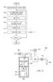
- FIG. 7is a flow chart illustrating one embodiment of a method for reducing hold-up volume at a multi-stage pump.
- FIG. 8is a diagrammatic representation of a single stage pump.
- FIGURESPreferred embodiments of the invention are illustrated in the FIGURES, like numerals being used to refer to like and corresponding parts of the various drawings.
- Embodiments of the inventionprovide a system and method for reducing the hold-up volume of a pump. More particularly, embodiments of the invention provide a system and method for determining a home position to reduce hold-up volume at a dispense pump and/or a feed pump.
- the home position for the diaphragmcan be selected such that the volume of the chamber at the dispense pump and/or feed pump contains sufficient fluid to perform the various steps of a dispense cycle while minimizing the hold-up volume. Additionally, the home position of the diaphragm can be selected to optimize the effective range of positive displacement.
- FIG. 1is a diagrammatic representation of a pumping system 10 .
- the pumping system 10can include a fluid source 15 , a pump controller 20 and a multiple stage (“multi-stage”) pump 100 , which work together to dispense fluid onto a wafer 25 .
- the operation of multi-stage pump 100can be controlled by pump controller 20 , which can be onboard multi-stage pump 100 or connected to multi-stage pump 100 via one or more communications links for communicating control signals, data or other information.
- Pump controller 20can include a computer readable medium 27 (e.g., RAM, ROM, Flash memory, optical disk, magnetic drive or other computer readable medium) containing a set of control instructions 30 for controlling the operation of multi-stage pump 100 .
- a computer readable medium 27e.g., RAM, ROM, Flash memory, optical disk, magnetic drive or other computer readable medium
- a processor 35(e.g., CPU, ASIC, RISC or other processor) can execute the instructions.
- controller 20communicates with multi-stage pump 100 via communications links 40 and 45 .
- Communications links 40 and 45can be networks (e.g., Ethernet, wireless network, global area network, DeviceNet network or other network known or developed in the art), a bus (e.g., SCSI bus) or other communications link.
- Pump controller 20can include appropriate interfaces (e.g., network interfaces, I/O interfaces, analog to digital converters and other components) to allow pump controller 20 to communicate with multi-stage pump 100 .
- Pump controller 20includes a variety of computer components known in the art including processors, memories, interfaces, display devices, peripherals or other computer components.
- Pump controller 20controls various valves and motors in multi-stage pump to cause multi-stage pump to accurately dispense fluids, including low viscosity fluids (i.e., less than 5 centipoises) or other fluids. It should be noted that while FIG. 1 uses the example of a multi-stage pump, pumping system 10 can also use a single stage pump.
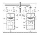
- FIG. 2is a diagrammatic representation of a multi-stage pump 100 .
- Multi-stage pump 100includes a feed stage portion 105 and a separate dispense stage portion 110 .
- filter 120Located between feed stage portion 105 and dispense stage portion 110 , from a fluid flow perspective, is filter 120 to filter impurities from the process fluid.
- a number of valvescan control fluid flow through multi-stage pump 100 including, for example, inlet valve 125 , isolation valve 130 , barrier valve 135 , purge valve 140 , vent valve 145 and outlet valve 147 .
- Dispense stage portion 110can further include a pressure sensor 112 that determines the pressure of fluid at dispense stage 110 .
- Feed stage 105 and dispense stage 110can include rolling diaphragm pumps to pump fluid in multi-stage pump 100 .
- Feed-stage pump 150(“feed pump 150 ”), for example, includes a feed chamber 155 to collect fluid, a feed stage diaphragm 160 to move within feed chamber 155 and displace fluid, a piston 165 to move feed stage diaphragm 160 , a lead screw 170 and a feed motor 175 .
- Lead screw 170couples to feed motor 175 through a nut, gear or other mechanism for imparting energy from the motor to lead screw 170 .
- feed motor 175rotates a nut that, in turn, rotates lead screw 170 , causing piston 165 to actuate.
- Dispense-stage pump 180(“dispense pump 180 ”) can similarly include a dispense chamber 185 , a dispense stage diaphragm 190 , a piston 192 , a lead screw 195 , and a dispense motor 200 .
- feed stage 105 and dispense stage 110can each include a variety of other pumps including pneumatically actuated pumps, hydraulic pumps or other pumps.
- pneumatically actuated pumpfor the feed stage and a stepper motor driven dispense pump is described in U.S. patent application Ser. No. 11/051,576, which is hereby fully incorporated by reference herein.
- Feed motor 175 and dispense motor 200can be any suitable motor.
- dispense motor 200is a Permanent-Magnet Synchronous Motor (“PMSM”) with a position sensor 203 .
- the PMSMcan be controlled by a digital signal processor (“DSP”) utilizing Field-Oriented Control (“FOC”) at motor 200 , a controller onboard multi-stage pump 100 or a separate pump controller (e.g., as shown in FIG. 1 ).
- Position sensor 203can be an encoder (e.g., a fine line rotary position encoder) for real time feedback of motor 200 's position.
- position sensor 203gives accurate and repeatable control of the position of piston 192 , which leads to accurate and repeatable control over fluid movements in dispense chamber 185 .
- a PMSMcan run at low velocities with little or no vibration.
- Feed motor 175can also be a PMSM or a stepper motor.
- valves of multi-stage pump 100are opened or closed to allow or restrict fluid flow to various portions of multi-stage pump 100 .
- these valvescan be pneumatically actuated (i.e., gas driven) diaphragm valves that open or close depending on whether pressure or a vacuum is asserted.
- any suitable valvecan be used.
- the dispense cycle multi-stage pump 100can include a ready segment, dispense segment, fill segment, pre-filtration segment, filtration segment, vent segment, purge segment and static purge segment. Additional segments can also be included to account for delays in valve openings and closings. In other embodiments the dispense cycle (i.e., the series of segments between when multi-stage pump 100 is ready to dispense to a wafer to when multi-stage pump 100 is again ready to dispense to wafer after a previous dispense) may require more or fewer segments and various segments can be performed in different orders.
- inlet valve 125is opened and feed stage pump 150 moves (e.g., pulls) feed stage diaphragm 160 to draw fluid into feed chamber 155 .
- inlet valve 125is closed.
- feed-stage pump 150moves feed stage diaphragm 160 to displace fluid from feed chamber 155 .
- Isolation valve 130 and barrier valve 135are opened to allow fluid to flow through filter 120 to dispense chamber 185 .
- Isolation valve 130can be opened first (e.g., in the “pre-filtration segment”) to allow pressure to build in filter 120 and then barrier valve 135 opened to allow fluid flow into dispense chamber 185 .
- pump 150can assert pressure on the fluid before pump 180 retracts, thereby also causing the pressure to build.
- Feed-stage pump 150applies pressure to the fluid to remove air bubbles from filter 120 through open vent valve 145 by forcing fluid out the vent.
- Feed-stage pump 150can be controlled to cause venting to occur at a predefined rate, allowing for longer vent times and lower vent rates, thereby allowing for accurate control of the amount of vent waste.
- isolation valve 130is closed, barrier valve 135 , if it is open in the vent segment, is closed, vent valve 145 closed, and purge valve 140 opened.
- Dispense pump 180applies pressure to the fluid in dispense chamber 185 .
- the fluidcan be routed out of multi-stage pump 100 or returned to the fluid supply or feed-pump 150 .
- purge valve 140remains open to relieve pressure built up during the purge segment. Any excess fluid removed during the purge or static purge segments can be routed out of multi-stage pump 100 (e.g., returned to the fluid source or discarded) or recycled to feed-stage pump 150 .
- all the valvescan be closed.
- outlet valve 147opens and dispense pump 180 applies pressure to the fluid in dispense chamber 185 . Because outlet valve 147 may react to controls more slowly than dispense pump 180 , outlet valve 147 can be opened first and some predetermined period of time later dispense motor 200 started. This prevents dispense pump 180 from pushing fluid through a partially opened outlet valve 147 . In other embodiments, the pump can be started before outlet valve 147 is opened or outlet valve 147 can be opened and dispense begun by dispense pump 180 simultaneously.
- An additional suckback segmentcan be performed in which excess fluid in the dispense nozzle is removed by pulling the fluid back.
- outlet valve 147can close and a secondary motor or vacuum can be used to suck excess fluid out of the outlet nozzle.
- outlet valve 147can remain open and dispense motor 200 can be reversed to such fluid back into the dispense chamber.
- the suckback segmenthelps prevent dripping of excess fluid onto the wafer.
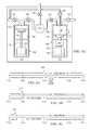
- FIGS. 3A-3Gprovide diagrammatic representations of multi-stage pump 100 during various segments of operation in which multi-stage pump 100 does not compensate for hold up volume.
- dispense pump 180 and feed pump 150each have a 20 mL maximum available capacity
- the dispense processdispenses 4 mL of fluid
- the vent segmentvents 0.5 mL of fluid
- the purge segment(including static purge) purges 1 mL of fluid and the suckback volume is 1 mL.
- isolation valve 130 and barrier valve 135are open while inlet valve 125 , vent valve 145 , purge valve 140 and outlet valve 147 are closed.
- Dispense pump 180will be near its maximum volume (e.g., 19 mL) (i.e., the maximum volume minus the 1 mL purged from the previous cycle).
- maximum volumee.g. 19 mL
- isolation valve 130 , barrier valve 135 , purge valve 140 , vent valve 145 and inlet valve 125are closed and outlet valve 147 is opened.
- Dispense pump 180dispenses a predefined amount of fluid (e.g., 4 mL). In this example, at the end of the dispense segment, dispense pump 180 will have a volume of 15 mL.
- some of the fluid (e.g., 1 mL) dispensed during the dispense segmentcan be sucked back into dispense pump 180 to clear the dispense nozzle. This can be done, for example, by reversing the dispense motor. In other embodiments, the additional 1 mL of fluid can be removed from the dispense nozzle by a vacuum or another pump. Using the example in which the 1 mL is sucked back into dispense pump 180 , after the suckback segment, dispense pump 180 will have a volume of 16 mL.
- outlet valve 147is closed and inlet valve 125 is opened.
- Feed pump 150in prior system, fills with fluid to its maximum capacity (e.g., 20 mL).
- inlet valve 125is closed and isolation valve 130 and barrier valve 135 opened.
- Feed pump 150pushes fluid out of feed pump 150 through filter 120 , causing fluid to enter dispense pump 180 .
- dispense pump 180is filled to its maximum capacity (e.g., 20 mL) during this segment.
- feed pump 150will displace 4 mL of fluid to cause dispense pump 180 to fill from 16 mL (the volume at the end of the suckback segment) to 20 mL (dispense pump 180 's maximum volume). This will leave feed pump 150 with 16 mL of volume.
- barrier valve 135can be closed or open and vent valve 145 is open.
- Feed pump 150displaces a predefined amount of fluid (e.g., 0.5 mL) to force excess fluid or gas bubbles accumulated at filter 120 out vent valve 145 .
- feed pump 150is at 15.5 mL.
- Dispense pump 180during the purge segment ( FIG. 3G ) can purge a small amount of fluid (e.g., 1 mL) through open purge valve 140 .
- the fluidcan be sent to waste or re-circulated.
- multi-stage pump 100is back to the ready segment, with the dispense pump at 19 mL.
- dispense pump 180only uses 5 mL of fluid, 4 mL for the dispense segment (1 mL of which is recovered in suckback) and 1 mL for the purge segment.
- feed pump 150only uses 4 mL to recharge dispense pump 180 in the filtration segment (4 mL to recharge for the dispense segment minus 1 mL recovered during suckback plus 1 mL to recharge for the purge segment) and 0.5 mL in the vent segment. Because both feed pump 150 and dispense pump 180 are filled to their maximum available volume (e.g., 20 mL each) there is a relatively large hold-up volume.
- Feed pump 150for example, has a hold-up volume of 15.5 mL and dispense pump 180 has a hold-up volume of 15 mL, for a combined hold-up volume of 30.5 mL.
- the hold-up volumeis slightly reduced if fluid is not sucked back into the dispense pump during the suckback segment.
- the dispense pump 180still uses 5 mL of fluid, 4 mL during the dispense segment and 1 mL during the purge segment.
- feed pump 150using the example above, must recharge the 1 mL of fluid that is not recovered during suckback. Consequently feed pump 150 will have to recharge dispense pump 180 with 5 mL of fluid during the filtration segment.
- feed pump 150will have a hold-up volume of 14.5 mL and dispense pump 180 will have a hold up volume of 15 mL.
- the home position of the feed and dispense pumpscan be defined such that the fluid capacity of the dispense pump is sufficient to handle a given “recipe” (i.e., a set of factors affecting the dispense operation including, for example, a dispense rate, dispense time, purge volume, vent volume or other factors that affect the dispense operation), a given maximum recipe or a given set of recipes.
- the home position of a pumpis then defined as the position of the pump that has the greatest available volume for a given cycle.
- the home positioncan be the diaphragm position that gives a greatest allowable volume during a dispense cycle.
- the available volume corresponding to the home position of the pumpwill typically be less than the maximum available volume for the pump.
- V DMaxV D +V P +e 1 [EQN 1]
- V FMaxV D +V P +V V ⁇ V suckback +e 2 [EQN 2]
- the V suckback termcan be set to 0 or dropped.
- e 1 and e 2can be zero, a predefined volume (e.g., 1 mL), calculated volumes or other error factor.
- e 1 and e 2can have the same value or different values (assumed to be zero in the previous example).
- dispense pump 180will have a volume of 4 mL and feed pump 150 will have a volume of 0 mL.
- Dispense pump 180during the dispense segment ( FIG. 3B ), dispenses 4 mL of fluid and recovers 1 mL during the suckback segment ( FIG. 3C ).
- feed pump 150recharges to 4.5 mL.
- feed pump 150can displace 4 mL of fluid causing dispense pump 180 to fill to 5 mL of fluid. Additionally, during the vent segment, feed pump 150 can vent 0.5 mL of fluid ( FIG. 3F ). Dispense pump 180 , during the purge segment ( FIG. 3G ) can purge 1 mL of fluid to return to the ready segment. In this example, there is no hold-up volume as all the fluid in the feed segment and dispense segment is moved.
- the home position, of the dispense pump and feed pumpcan be selected as the home position that can handle the largest recipe.
- Table 1, below,provides example recipes for a multi-stage pump.
- V DV DPre +V DMain [EQN. 3]
- the home position of the dispense diaphragmcan be set for a volume of 4.5 mL (3+1+0.5) and the home position of the feed pump can be set to 4.75 mL (3+1+0.5+0.25). With these home positions, dispense pump 180 and feed pump 150 will have sufficient capacity for Recipe 1 or Recipe 2.
- the home position of the dispense pump or feed pumpcan change based on the active recipe or a user-defined position. If a user adjusts a recipe to change the maximum volume required by the pump or the pump adjusts for a new active recipe in a dispense operation, say by changing Recipe 2 to require 4 mL of fluid, the dispense pump (or feed pump) can be adjusted manually or automatically. For example, the dispense pump diaphragm position can move to change the capacity of the dispense pump from 3 mL to 4 mL and the extra 1 mL of fluid can be added to the dispense pump. If the user specifies a lower volume recipe, say changing Recipe 2 to only require 2.5 mL of fluid, the dispense pump can wait until a dispense is executed and refill to the new lower required capacity.
- a lower volume recipesay changing Recipe 2 to only require 2.5 mL of fluid
- the home position of the feed pump or dispense pumpcan also be adjusted to compensate for other issues such as to optimize the effective range of a particular pump.
- the maximum and minimum ranges for a particular pump diaphragme.g., a rolling edge diaphragm, a flat diaphragm or other diaphragm known in the art
- the home position of a pumpcan be set to a stressed position for a large fluid capacity or to a lower stress position where the larger fluid capacity is not required.
- the home position of the diaphragmcan be adjusted to position the diaphragm in an effective range.
- dispense pump 180that has a 10 mL capacity may have an effective range between 2 and 8 mL.
- the effective rangecan be defined as the linear region of a dispense pump where the diaphragm does not experience significant loading.
- FIGS. 4A-Cprovide diagrammatic representations of three examples of setting the home position of a dispense diaphragm (e.g., dispense diaphragm 190 of FIG. 2 ) for a 10 mL pump having a 6 mL effective range between 2 mL and 8 mL.
- 0 mLindicates a diaphragm position that would cause the dispense pump to have a 10 mL available capacity and a 10 mL position would cause the dispense pump to have a 0 mL capacity.
- the 0 mL-10 mL scalerefers to the displaced volume.
- the diaphragm of the dispense pumpcan be set so that the volume of the dispense pump is 5 mL (represented at 205 ). This provides sufficient volume for the 3 mL dispense process while not requiring use of 0 mL to 2 mL or 8 mL to 10 mL region that causes stress.
- the home positioncan account for the non-stressed effective region of the pump.
- FIG. 4Bprovides a diagrammatic representation of a second example.
- the dispense pumpruns an 8 mL maximum volume dispense process and a 3 mL maximum volume dispense process.
- the diaphragm home positioncan be set to provide a maximum allowable volume of 8 mL (represented at 210 ) for both processes (i.e., can be set at a position to allow for 8 mL of fluid).
- the smaller volume dispense processwill occur entirely within the effective range.
- the home positionis selected to utilize the lower-volume less effective region (i.e., the less-effective region that occurs when the pump is closer to empty).
- the home positioncan be in the higher-volume less effective region. However, this will mean that part of the lower volume dispense will occur in the less-effective region and, in the example of FIG. 4B , there will be some hold-up volume.
- the dispense pumpruns a 9 mL maximum volume dispense process and a 4 mL maximum volume dispense process. Again, a portion of the process will occur in the less effective range.
- the dispense diaphragmin this example, can be set to a home position to provide a maximum allowable volume of 9 mL (e.g., represented at 215 ). If, as described above, the same home position is used for each recipe, a portion of the 4 mL dispense process will occur in the less effective range. According to other embodiments, the home position can reset for the smaller dispense process into the effective region.
- dispense pump 180can include a dispense motor 200 with a position sensor 203 (e.g., a rotary encoder).
- Position sensor 203can provide feedback of the position of lead screw 195 and, hence, the position of lead screw 195 will correspond to a particular available volume in dispense chamber 185 as the lead screw displaces diaphragm. Consequently, the pump controller can select a position for the lead screw such that the volume in the dispense chamber is at least V DMax .
- the home positioncan be user selected or user programmed. For example, using a graphical user interface or other interface, a user can program a user selected volume that is sufficient to carry out the various dispense processes or active dispense process by the multi-stage pump. According to one embodiment, if the user selected volume is less than V Dispense +V Purge , an error can be returned.
- the pump controllere.g., pump controller 20
- the pump controllercan add an error volume to the user specified volume. For example, if the user selects 5 cc as the user specified volume, pump controller 20 can add 1 cc to account for errors. Thus, pump controller will select a home position for dispense pump 180 that has corresponding available volume of 6 cc.
- dispense pump 180can be accurately controlled such that at the end of the filtration cycle, dispense pump 180 is at its home position (i.e., its position having the greatest available volume for the dispense cycle). It should be noted that feed pump 150 can be controlled in a similar manner using a position sensor.
- dispense pump 180 and/or feed pump 150can be driven by a stepper motor without a position sensor.
- Each step or count of a stepper motorwill correspond to a particular displacement of the diaphragm.
- each count of dispense motor 200will displace dispense diaphragm 190 a particular amount and therefore displace a particular amount of fluid from dispense chamber 185 .
- C fullstrokeDis the counts to displace dispense diaphragm from the position in which dispense chamber 185 has its maximum volume (e.g., 20 mL) to 0 mL (i.e., the number of counts to move dispense diaphragm 190 through its maximum range of motion)
- C Pis the number of counts to displace V P
- C Dis the number of counts to displace V D
- the home position of stepper motor 200can be:
- C HomeDC fullstrokeD ⁇ ( C P +C D +C e1 ) [EQN 3]
- C e1is a number of counts corresponding to an error volume.
- C fullstrokeFis the counts to displace feed diaphragm 160 from the position in which dispense chamber 155 has its maximum volume (e.g., 20 mL) to 0 mL (i.e., the number of counts to move dispense diaphragm 160 through its maximum range of motion)
- C Sis the number of counts at the feed motor 175 corresponding to V suckback recovered at dispense pump 180 and C V is the number of counts at feed motor 175 to displace V V
- the home position of feed motor 175can be:
- C HomeFC fullstrokeF ⁇ ( C P +C D ⁇ C S +C e2 ) [EQN 4]
- C e2is a number of counts corresponding to an error volume.
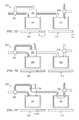
- FIGS. 5A-5Kprovide diagrammatic representations of various segments for a multi-stage pump 500 according to another embodiment of the invention.
- Multi-stage pump 500includes a feed stage pump 501 (“feed pump 501 ”), a dispense stage pump 502 (“dispense pump 502 ”), a filter 504 , an inlet valve 506 and an outlet valve 508 .
- Inlet valve 506 and outlet valve 508can be three-way valves. As will be described below, this allows inlet valve 506 to be used both as an inlet valve and isolation valve and outlet valve 508 to be used as an outlet valve and purge valve.
- Feed pump 501 and dispense pump 502can be motor driven pumps (e.g., stepper motors, brushless DC motors or other motor). Shown at 510 and 512 , respectively, are the motor positions for the feed pump 501 and dispense pump 502 . The motor positions are indicated by the corresponding amount of fluid available in the feed chamber or dispense chamber of the respective pump. In the example of FIGS. 5A-5K , each pump has a maximum available volume of 20 cc. For each segment, the fluid movement is depicted by the arrows.
- FIG. 5Ais a diagrammatic representation of multi-stage pump 500 at the ready segment.
- feed pump 501has a motor position that provides for 7 cc of available volume and dispense pump 502 has a motor position that provides for 6 cc of available volume.
- the motor of dispense pump 502moves to displace 5.5 cc of fluid through outlet valve 508 .
- the dispense pumprecovers 0.5 cc of fluid during the suckback segment (depicted in FIG. 5C ).
- dispense pump 502displaces 1 cc of fluid through outlet valve 508 .
- the motor of dispense pump 502can be driven to a hard stop (i.e., to 0 cc of available volume). This can ensure that the motor is backed the appropriate number of steps in subsequent segments.
- feed pump 501can push a small amount of fluid through filter 502 .
- feed pump 501can begin pushing fluid to dispense pump 502 before dispense pump 502 recharges. This slightly pressurizes fluid to help fill dispense pump 502 and prevents negative pressure in filter 504 . Excess fluid can be purged through outlet valve 508 .
- outlet valve 508is closed and fluid fills dispense pump 502 .
- 6 cc of fluidis moved by feed pump 501 to dispense pump 502 .
- Feed pump 501can continue to assert pressure on the fluid after the dispense motor has stopped (e.g., as shown in the feed delay segment of FIG. 5H ). In the example of FIG. 5H , there is approximately 0.5 cc of fluid left in feed pump 501 .
- feed pump 501can be driven to a hard stop (e.g., with 0 cc of available volume), as shown in FIG. 5I .
- feed pump 501is recharged with fluid and multi-stage pump 500 returns to the ready segment (shown in FIGS. 5K and 5A ).
- the purge segmentoccurs immediately after the suckback segment to bring dispense pump 502 to a hardstop, rather than after the vent segment as in the embodiment of FIG. 2 .
- the dispense volumeis 5.5 cc
- the suckback volume0.5 cc
- V DMaxV Dispense + V Purge ⁇ V Suckback +e 1 [EQN 5]
- dispense pump 502utilizes a stepper motor, a specific number of counts will result in a displacement of V DMax .
- a hardstop positione.g., 0 counts
- dispense pumpwill have an available volume of V DMax .
- V Ventis 0.5 cc, and there is an additional error volume of 0.5 cc to bring feed pump 501 to a hardstop.
- V FMax5.5+1+0.5 ⁇ 0.5+0.5
- V FMaxis 7 cc. If feed pump 501 uses a stepper motor, the stepper motor, during the recharge segment can be backed from the hardstop position the number of counts corresponding to 7 cc. In this example, feed pump 501 utilized 7 cc of a maximum 20 cc and feed pump 502 utilized 6 cc of a maximum 20 cc, thereby saving 27 cc of hold-up volume.
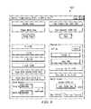
- FIG. 6is a diagrammatic representation illustrating a user interface 600 for entering a user defined volume.
- a userat field 602 , can enter a user defined volume, here 10.000 mL.
- An error volumecan be added to this (e.g., 1 mL), such that the home position of the dispense pump has a corresponding available volume of 11 mL.
- FIG. 6only depicts setting a user selected volume for the dispense pump, the user, in other embodiments, can also select a volume for the feed pump.
- FIG. 7is a diagrammatic representation of one embodiment of a method for controlling a pump to reduce the hold-up volume.
- Embodiments of the inventioncan be implemented, for example, as software programming executable by a computer processor to control the feed pump and dispense pump.
- the userenters one or more parameters for a dispense operation, which may include multiple dispense cycles, including, for example, the dispense volume, purge volume, vent volume, user specified volumes for the dispense pump volume and/or feed pump and other parameters.
- the parameterscan include parameters for various recipes for different dispense cycles.
- the pump controllere.g., pump controller 20 of FIG. 1
- the pump controllercan determine the home position of the dispense pump based on a user specified volume, dispense volume, purge volume or other parameter associated with the dispense cycle. Additionally, the choice of home position can be based on the effective range of motion of the dispense diaphragm. Similarly, the pump controller can determine the feed pump home position.
- the feed pumpcan be controlled to fill with a process fluid.
- the feed pumpcan be filled to its maximum capacity.
- the feed pumpcan be filled to a feed pump home position (step 704 ).
- the feed pumpcan be further controlled to vent fluid having a vent volume (step 706 ).
- the feed pumpis controlled to assert pressure on the process fluid to fill the dispense pump until the dispense pump reaches its home position.
- the dispense diaphragm in the dispense pumpis moved until the dispense pump reaches the home position to partially fill the dispense pump (i.e., to fill the dispense pump to an available volume that is less than the maximum available volume of the dispense pump) (step 708 ).
- the dispense pumpuses a stepper motor
- the dispense diaphragmcan first be brought to a hard stop and the stepper motor reversed a number of counts corresponding to the dispense pump home position.
- the dispense pumpuses a position sensor (e.g., a rotary encoder)
- the position of the diaphragmcan be controlled using feedback from the position sensor.
- the dispense pumpcan then be directed purge a small amount of fluid (step 710 ).
- the dispense pumpcan be further controlled to dispense a predefined amount of fluid (e.g., the dispense volume) (step 712 ).
- the dispense pumpcan be further controlled to suckback a small amount of fluid or fluid can be removed from a dispense nozzle by another pump, vacuum or other suitable mechanism. It should be noted that steps of FIG. 7 can be performed in a different order and repeated as needed or desired.
- FIG. 8is a diagrammatic representation of one embodiment of a single stage pump 800 .
- Single stage pump 800includes a dispense pump 802 and filter 820 between dispense pump 802 and the dispense nozzle 804 to filter impurities from the process fluid.
- a number of valvescan control fluid flow through single stage pump 800 including, for example, purge valve 840 and outlet valve 847 .
- Dispense pump 802can include, for example, a dispense chamber 855 to collect fluid, a diaphragm 860 to move within dispense chamber 855 and displace fluid, a piston 865 to move dispense stage diaphragm 860 , a lead screw 870 and a dispense motor 875 .
- Lead screw 870couples to motor 875 through a nut, gear or other mechanism for imparting energy from the motor to lead screw 870 .
- feed motor 875rotates a nut that, in turn, rotates lead screw 870 , causing piston 865 to actuate.
- dispense pump 802can include a variety of other pumps including pneumatically actuated pumps, hydraulic pumps or other pumps.
- Dispense motor 875can be any suitable motor. According to one embodiment, dispense motor 875 is a PMSM with a position sensor 880 .
- the PMSMcan be controlled by a DSP FOC at motor 875 , a controller onboard pump 800 or a separate pump controller (e.g., as shown in FIG. 1 ).
- Position sensor 880can be an encoder (e.g., a fine line rotary position encoder) for real time feedback of motor 875 's position. The use of position sensor 880 gives accurate and repeatable control of the position of dispense pump 802 .
- valves of single stage pump 800are opened or closed to allow or restrict fluid flow to various portions of single stage pump 800 .
- these valvescan be pneumatically actuated (i.e., gas driven) diaphragm valves that open or close depending on whether pressure or a vacuum is asserted.
- any suitable valvecan be used.
- the dispense cycle of single stage pump 100can include a ready segment, filtration/dispense segment, vent/purge segment and static purge segment. Additional segments can also be included to account for delays in valve openings and closings.
- the dispense cyclei.e., the series of segments between when single stage pump 800 is ready to dispense to a wafer to when single stage pump 800 is again ready to dispense to wafer after a previous dispense
- inlet valve 825is opened and dispense pump 802 moves (e.g., pulls) diaphragm 860 to draw fluid into dispense chamber 855 .
- inlet valve 825is closed.
- pump 802moves diaphragm 860 to displace fluid from dispense chamber 855 .
- Outlet valve 847is opened to allow fluid to flow through filter 820 out nozzle 804 . Outlet valve 847 can be opened before, after or simultaneous to pump 802 beginning dispense.
- purge valve 840is opened and outlet valve 847 closed.
- Dispense pump 802applies pressure to the fluid to move fluid through open purge valve 840 .
- the fluidcan be routed out of single stage pump 800 or returned to the fluid supply or dispense pump 802 .
- purge valve 140remains open to relieve pressure built up during the purge segment.
- An additional suckback segmentcan be performed in which excess fluid in the dispense nozzle is removed by pulling the fluid back.
- outlet valve 847can close and a secondary motor or vacuum can be used to suck excess fluid out of the outlet nozzle 804 .
- outlet valve 847can remain open and dispense motor 875 can be reversed to suck fluid back into the dispense chamber.
- the suckback segmenthelps prevent dripping of excess fluid onto the wafer.
- the single stage pumpis not limited to performing the segments described above in the order described above.
- dispense motor 875is a stepper motor
- a segmentcan be added to bring the motor to a hard stop before the feed segment.
- the combined segmentse.g., purge/vent
- the pumpmay not perform the suckback segment.
- the single stage pumpcan have different configurations.
- the single stage pumpmay not include a filter or rather than having a purge valve, can have a check valve for outlet valve 147 .
- dispense pump 802can be filled to home position such that dispense chamber 855 has sufficient volume to perform each of the segments of the dispense cycle.
- the available volume corresponding to the home positionwould be at least the dispense volume plus the purge volume (i.e., the volume released during the purge/vent segment and static purge segment). Any suckback volume recovered into dispense chamber 855 can be subtracted from the dispense volume and purge volume.
- the home positioncan be determined based on one or more recipes or a user specified volume. The available volume corresponding to the dispense pump home position is less than the maximum available volume of the dispense pump and is the greatest available volume for the dispense pump in a dispense cycle.
Landscapes
- Engineering & Computer Science (AREA)
- General Engineering & Computer Science (AREA)
- Mechanical Engineering (AREA)
- Computer Hardware Design (AREA)
- General Physics & Mathematics (AREA)
- Manufacturing & Machinery (AREA)
- Microelectronics & Electronic Packaging (AREA)
- Power Engineering (AREA)
- Physics & Mathematics (AREA)
- Condensed Matter Physics & Semiconductors (AREA)
- Reciprocating Pumps (AREA)
- Details Of Reciprocating Pumps (AREA)
- Control Of Positive-Displacement Pumps (AREA)
Abstract
Description
VDMax=VD+VP+e1 [EQN 1]
- VDMax=maximum volume required by dispense pump
- VD=volume dispensed during dispense segment
- VP=volume purged during purge segment
- e1=an error volume applied to dispense pump
VFMax=VD+VP+VV−Vsuckback+e2 [EQN 2]
- VFMax=maximum volume required by dispense pump
- VD=volume dispensed during dispense segment
- VP=volume purged during purge segment
- VV=volume vented during vent segment
- Vsuckback=volume recovered during suckback
- e2=error volume applied to feed pump
| TABLE 1 | |||
| RECIPE 1 | |||
| Name: | Main Dispense 1 | Main Dispense 2 |
| Dispense Rate | 1.5 | mL/sec | 1 | mL/sec | ||
| Dispense | 2 | sec | 2.5 | sec | ||
| Resulting Volume | 3 | mL | 2.5 | mL | ||
| Purge | 0.5 | mL | 0.5 | mL | ||
| Vent | 0.25 | mL | 0.25 | mL | ||
| Predispense Rate | 1 | mL/sec | 0.5 | mL/sec | ||
| Predispense Volume | 1 | mL | 0.5 | mL | ||
VD=VDPre+VDMain [EQN. 3]
- VDPre=amount of pre-dispense dispense
- VDMain=amount of main dispense
CHomeD=CfullstrokeD−(CP+CD+Ce1) [EQN 3]
CHomeF=CfullstrokeF−(CP+CD−CS+Ce2) [EQN 4]
VDMax=VDispense+VPurge−VSuckback+e1 [EQN 5]
VFMax=5.5+1+0.5−0.5+0.5
Claims (20)
Priority Applications (1)
| Application Number | Priority Date | Filing Date | Title |
|---|---|---|---|
| US14/466,115US9617988B2 (en) | 2004-11-23 | 2014-08-22 | System and method for variable dispense position |
Applications Claiming Priority (6)
| Application Number | Priority Date | Filing Date | Title |
|---|---|---|---|
| US63038404P | 2004-11-23 | 2004-11-23 | |
| PCT/US2005/042127WO2006057957A2 (en) | 2004-11-23 | 2005-11-21 | System and method for a variable home position dispense system |
| US11/666,124US8292598B2 (en) | 2004-11-23 | 2005-11-21 | System and method for a variable home position dispense system |
| US66612407A | 2007-04-24 | 2007-04-24 | |
| US13/554,746US8814536B2 (en) | 2004-11-23 | 2012-07-20 | System and method for a variable home position dispense system |
| US14/466,115US9617988B2 (en) | 2004-11-23 | 2014-08-22 | System and method for variable dispense position |
Related Parent Applications (1)
| Application Number | Title | Priority Date | Filing Date |
|---|---|---|---|
| US13/554,746ContinuationUS8814536B2 (en) | 2004-11-23 | 2012-07-20 | System and method for a variable home position dispense system |
Publications (2)
| Publication Number | Publication Date |
|---|---|
| US20140361046A1 US20140361046A1 (en) | 2014-12-11 |
| US9617988B2true US9617988B2 (en) | 2017-04-11 |
Family
ID=36498458
Family Applications (3)
| Application Number | Title | Priority Date | Filing Date |
|---|---|---|---|
| US11/666,124Active2028-04-27US8292598B2 (en) | 2004-11-23 | 2005-11-21 | System and method for a variable home position dispense system |
| US13/554,746ActiveUS8814536B2 (en) | 2004-11-23 | 2012-07-20 | System and method for a variable home position dispense system |
| US14/466,115ActiveUS9617988B2 (en) | 2004-11-23 | 2014-08-22 | System and method for variable dispense position |
Family Applications Before (2)
| Application Number | Title | Priority Date | Filing Date |
|---|---|---|---|
| US11/666,124Active2028-04-27US8292598B2 (en) | 2004-11-23 | 2005-11-21 | System and method for a variable home position dispense system |
| US13/554,746ActiveUS8814536B2 (en) | 2004-11-23 | 2012-07-20 | System and method for a variable home position dispense system |
Country Status (7)
| Country | Link |
|---|---|
| US (3) | US8292598B2 (en) |
| EP (1) | EP1859169A2 (en) |
| JP (3) | JP5079516B2 (en) |
| KR (2) | KR101231945B1 (en) |
| CN (1) | CN101155992B (en) |
| TW (1) | TWI409386B (en) |
| WO (1) | WO2006057957A2 (en) |
Families Citing this family (46)
| Publication number | Priority date | Publication date | Assignee | Title |
|---|---|---|---|---|
| US8172546B2 (en)* | 1998-11-23 | 2012-05-08 | Entegris, Inc. | System and method for correcting for pressure variations using a motor |
| US7029238B1 (en) | 1998-11-23 | 2006-04-18 | Mykrolis Corporation | Pump controller for precision pumping apparatus |
| US6325932B1 (en) | 1999-11-30 | 2001-12-04 | Mykrolis Corporation | Apparatus and method for pumping high viscosity fluid |
| KR101231945B1 (en) | 2004-11-23 | 2013-02-08 | 엔테그리스, 아이엔씨. | System and method for a variable home position dispense system |
| US8753097B2 (en) | 2005-11-21 | 2014-06-17 | Entegris, Inc. | Method and system for high viscosity pump |
| WO2007061956A2 (en) | 2005-11-21 | 2007-05-31 | Entegris, Inc. | System and method for a pump with reduced form factor |
| US8029247B2 (en) | 2005-12-02 | 2011-10-04 | Entegris, Inc. | System and method for pressure compensation in a pump |
| US7547049B2 (en) | 2005-12-02 | 2009-06-16 | Entegris, Inc. | O-ring-less low profile fittings and fitting assemblies |
| EP1958039B9 (en) | 2005-12-02 | 2011-09-07 | Entegris, Inc. | I/o systems, methods and devices for interfacing a pump controller |
| US8083498B2 (en) | 2005-12-02 | 2011-12-27 | Entegris, Inc. | System and method for position control of a mechanical piston in a pump |
| CN101356715B (en) | 2005-12-02 | 2012-07-18 | 恩特格里公司 | System and method for valve sequencing in a pump |
| US7850431B2 (en) | 2005-12-02 | 2010-12-14 | Entegris, Inc. | System and method for control of fluid pressure |
| US7878765B2 (en) | 2005-12-02 | 2011-02-01 | Entegris, Inc. | System and method for monitoring operation of a pump |
| WO2007067360A2 (en) | 2005-12-05 | 2007-06-14 | Entegris, Inc. | Error volume system and method for a pump |
| TWI402423B (en)* | 2006-02-28 | 2013-07-21 | Entegris Inc | System and method for operation of a pump |
| US7684446B2 (en) | 2006-03-01 | 2010-03-23 | Entegris, Inc. | System and method for multiplexing setpoints |
| US7494265B2 (en) | 2006-03-01 | 2009-02-24 | Entegris, Inc. | System and method for controlled mixing of fluids via temperature |
| US20080185044A1 (en)* | 2007-02-02 | 2008-08-07 | Entegris, Inc. | System and method of chemical dilution and dispense |
| US8684705B2 (en) | 2010-02-26 | 2014-04-01 | Entegris, Inc. | Method and system for controlling operation of a pump based on filter information in a filter information tag |
| US8727744B2 (en)* | 2010-02-26 | 2014-05-20 | Entegris, Inc. | Method and system for optimizing operation of a pump |
| TWI563351B (en) | 2010-10-20 | 2016-12-21 | Entegris Inc | Method and system for pump priming |
| JP5821773B2 (en)* | 2012-05-15 | 2015-11-24 | 株式会社島津製作所 | Control device and control method for reciprocating pump |
| US10422614B2 (en)* | 2012-09-14 | 2019-09-24 | Henkel IP & Holding GmbH | Dispenser for applying an adhesive to a remote surface |
| US9719504B2 (en)* | 2013-03-15 | 2017-08-01 | Integrated Designs, L.P. | Pump having an automated gas removal and fluid recovery system and method |
| DK3137768T3 (en)* | 2014-04-30 | 2021-01-18 | Anthony George Hurter | DEVICE AND PROCEDURE FOR CLEANING UP USED FUEL OIL WITH SUPER-CRITICAL WATER |
| JP6644712B2 (en) | 2014-05-28 | 2020-02-12 | インテグリス・インコーポレーテッド | System and method for operation of a pump with supply and dispense sensors, filtration and dispense confirmation, and vacuum priming of a filter |
| US10125002B2 (en)* | 2014-07-13 | 2018-11-13 | Sestra Systems, Inc | Beverage dispensing system |
| US10155208B2 (en)* | 2014-09-30 | 2018-12-18 | Taiwan Semiconductor Manufacturing Co., Ltd. | Liquid mixing system for semiconductor fabrication |
| US10121685B2 (en)* | 2015-03-31 | 2018-11-06 | Tokyo Electron Limited | Treatment solution supply method, non-transitory computer-readable storage medium, and treatment solution supply apparatus |
| CN110624717A (en) | 2015-06-01 | 2019-12-31 | 深圳市大疆创新科技有限公司 | Sprinkler system with feedback of liquid flow and rotational speed |
| WO2016192023A1 (en) | 2015-06-01 | 2016-12-08 | SZ DJI Technology Co., Ltd. | Brushless pump motor system |
| US20180209405A1 (en)* | 2015-08-13 | 2018-07-26 | Vindum Engineering Inc. | Improved pulse-free metering pump and methods relating thereto |
| DE102015116332B4 (en) | 2015-09-28 | 2023-12-28 | Tdk Electronics Ag | Arrester, method of manufacturing the arrester and method of operating the arrester |
| JP6685754B2 (en) | 2016-02-16 | 2020-04-22 | 株式会社Screenホールディングス | Pump device and substrate processing device |
| JP6765239B2 (en)* | 2016-07-12 | 2020-10-07 | 日本ピラー工業株式会社 | Diaphragm pump |
| KR101736168B1 (en)* | 2016-07-28 | 2017-05-17 | 한전원자력연료 주식회사 | Pulsed column having apparatus for supplying pulse |
| JP6739286B2 (en)* | 2016-08-24 | 2020-08-12 | 株式会社Screenホールディングス | Pump device and substrate processing device |
| US10774297B2 (en)* | 2017-08-03 | 2020-09-15 | Repligen Corporation | Method of actuation of an alternating tangential flow diaphragm pump |
| JP6920133B2 (en)* | 2017-08-23 | 2021-08-18 | 株式会社Screenホールディングス | Processing liquid supply device |
| US11077268B2 (en)* | 2017-10-25 | 2021-08-03 | General Electric Company | Anesthesia vaporizer reservoir and system |
| EP3712432B1 (en)* | 2019-03-19 | 2024-07-17 | Fast & Fluid Management B.V. | Liquid dispenser and method of operating such a dispenser |
| US11772234B2 (en) | 2019-10-25 | 2023-10-03 | Applied Materials, Inc. | Small batch polishing fluid delivery for CMP |
| CN113443279A (en)* | 2020-03-25 | 2021-09-28 | 长鑫存储技术有限公司 | Storage container and supply system |
| EP4320350A4 (en)* | 2021-04-08 | 2025-03-12 | Fluid Metering, Inc. | Fluid dispensing system |
| KR102458920B1 (en)* | 2022-02-21 | 2022-10-25 | 삼성전자주식회사 | Fluid supply device |
| JP7215790B1 (en) | 2022-07-07 | 2023-01-31 | Tlc株式会社 | dispenser |
Citations (240)
| Publication number | Priority date | Publication date | Assignee | Title |
|---|---|---|---|---|
| US269626A (en) | 1882-12-26 | brauee | ||
| US826018A (en) | 1904-11-21 | 1906-07-17 | Isaac Robert Concoff | Hose-coupling. |
| US1664125A (en) | 1926-11-10 | 1928-03-27 | John R Lowrey | Hose coupling |
| US2153664A (en) | 1937-03-08 | 1939-04-11 | Dayton Rubber Mfg Co | Strainer |
| US2215505A (en) | 1938-06-13 | 1940-09-24 | Byron Jackson Co | Variable capacity pumping apparatus |
| US2328468A (en) | 1940-12-07 | 1943-08-31 | Laffly Edmond Gabriel | Coupling device for the assembly of tubular elements |
| US2456765A (en) | 1945-04-18 | 1948-12-21 | Honeywell Regulator Co | Hot-wire bridge overspeed controller |
| US2457384A (en) | 1947-02-17 | 1948-12-28 | Ace Glass Inc | Clamp for spherical joints |
| GB661522A (en) | 1949-03-31 | 1951-11-21 | Eureka Williams Corp | Improvements in or relating to oil burners |
| US2631538A (en) | 1949-11-17 | 1953-03-17 | Wilford C Thompson | Diaphragm pump |
| US2673522A (en) | 1951-04-10 | 1954-03-30 | Bendix Aviat Corp | Diaphragm pump |
| US2757966A (en) | 1952-11-06 | 1956-08-07 | Samiran David | Pipe coupling |
| US3072058A (en) | 1961-08-18 | 1963-01-08 | Socony Mobil Oil Co Inc | Pipe line control system |
| US3227279A (en) | 1963-05-06 | 1966-01-04 | Conair | Hydraulic power unit |
| US3250225A (en) | 1964-07-13 | 1966-05-10 | John F Taplin | Mechanical system comprising feed pump having a rolling diaphragm |
| US3327635A (en) | 1965-12-01 | 1967-06-27 | Texsteam Corp | Pumps |
| US3623661A (en) | 1969-02-28 | 1971-11-30 | Josef Wagner | Feed arrangement for spray painting |
| US3741298A (en) | 1971-05-17 | 1973-06-26 | L Canton | Multiple well pump assembly |
| US3895748A (en) | 1974-04-03 | 1975-07-22 | George R Klingenberg | No drip suck back units for glue or other liquids either separately installed with or incorporated into no drip suck back liquid applying and control apparatus |
| US3954352A (en) | 1972-11-13 | 1976-05-04 | Toyota Jidosha Kogyo Kabushiki Kaisha | Diaphragm vacuum pump |
| JPS5181413A (en) | 1975-01-10 | 1976-07-16 | Nikkei Aluminium Sales | Sherutaaruino kumitatekoho |
| US3977255A (en) | 1975-08-18 | 1976-08-31 | Control Process, Incorporated | Evaluating pressure profile of material flowing to mold cavity |
| US4023592A (en) | 1976-03-17 | 1977-05-17 | Addressograph Multigraph Corporation | Pump and metering device |
| US4093403A (en) | 1976-09-15 | 1978-06-06 | Outboard Marine Corporation | Multistage fluid-actuated diaphragm pump with amplified suction capability |
| JPS5481119A (en) | 1977-12-12 | 1979-06-28 | Sumitomo Metal Ind Ltd | Nonmagnetic steel excellent in machinability |
| JPS5573563A (en) | 1978-11-29 | 1980-06-03 | Ricoh Co Ltd | Ink feed pump of ink jet printer |
| JPS58119983A (en) | 1982-01-12 | 1983-07-16 | ポラロイド・コ−ポレ−シヨン | Pump device |
| JPS58203340A (en) | 1982-05-20 | 1983-11-26 | Matsushita Electric Ind Co Ltd | Hot water feeder |
| US4452265A (en) | 1979-12-27 | 1984-06-05 | Loennebring Arne | Method and apparatus for mixing liquids |
| US4483665A (en) | 1982-01-19 | 1984-11-20 | Tritec Industries, Inc. | Bellows-type pump and metering system |
| JPS6067790A (en) | 1983-09-21 | 1985-04-18 | Tokyo Rika Kikai Kk | High pressure constant volume pump for liquid chromatography |
| US4541455A (en) | 1983-12-12 | 1985-09-17 | Tritec Industries, Inc. | Automatic vent valve |
| JPS6173090A (en) | 1984-09-19 | 1986-04-15 | 三菱重工業株式会社 | Liquid metal cooling type fast breeder reactor |
| US4597719A (en) | 1983-03-28 | 1986-07-01 | Canon Kabushiki Kaisha | Suck-back pump |
| US4597721A (en) | 1985-10-04 | 1986-07-01 | Valco Cincinnati, Inc. | Double acting diaphragm pump with improved disassembly means |
| US4601409A (en) | 1984-11-19 | 1986-07-22 | Tritec Industries, Inc. | Liquid chemical dispensing system |
| JPS61178582A (en) | 1985-02-01 | 1986-08-11 | Jeol Ltd | Liquid pump device |
| US4614438A (en) | 1984-04-24 | 1986-09-30 | Kabushiki Kaisha Kokusai Technicals | Method of mixing fuel oils |
| US4671545A (en) | 1985-01-29 | 1987-06-09 | Toyoda Gosei Co., Ltd. | Female-type coupling nipple |
| US4690621A (en) | 1986-04-15 | 1987-09-01 | Advanced Control Engineering | Filter pump head assembly |
| GB2189555A (en) | 1985-02-01 | 1987-10-28 | Jeol Ltd | Two-stage pump assembly |
| US4705461A (en) | 1979-09-19 | 1987-11-10 | Seeger Corporation | Two-component metering pump |
| EP0249655A1 (en) | 1985-12-05 | 1987-12-23 | Takeshi Hoya | Combined complex plant of diaphragm pumps |
| AU7887287A (en) | 1986-09-24 | 1988-04-14 | Board Of Trustees Of The Leland Stanford Junior University | Integrated, microminiature electric-to-fluidic valve and pressure/flow regulator |
| JPS63176681A (en) | 1987-01-17 | 1988-07-20 | Japan Spectroscopic Co | Reciprocating pump |
| JPS63255575A (en) | 1987-04-10 | 1988-10-21 | Yoshimoto Seisakusho:Kk | Pump device |
| US4797834A (en) | 1986-09-30 | 1989-01-10 | Honganen Ronald E | Process for controlling a pump to account for compressibility of liquids in obtaining steady flow |
| US4808077A (en) | 1987-01-09 | 1989-02-28 | Hitachi, Ltd. | Pulsationless duplex plunger pump and control method thereof |
| US4810168A (en) | 1986-10-22 | 1989-03-07 | Hitachi, Ltd. | Low pulsation pump device |
| US4821997A (en) | 1986-09-24 | 1989-04-18 | The Board Of Trustees Of The Leland Stanford Junior University | Integrated, microminiature electric-to-fluidic valve and pressure/flow regulator |
| US4865525A (en) | 1986-09-19 | 1989-09-12 | Grunbeck Wasseraufbereitung Gmbh | Metering pump |
| JPH0213184A (en) | 1988-06-30 | 1990-01-17 | Shimadzu Corp | Digital subtraction device |
| JPH0291485A (en) | 1988-09-27 | 1990-03-30 | Teijin Ltd | Liquid quantitative supply device |
| US4913624A (en) | 1987-08-11 | 1990-04-03 | Hitachi, Ltd. | Low pulsation displacement pump |
| US4915126A (en) | 1986-01-20 | 1990-04-10 | Dominator Maskin Ab | Method and arrangement for changing the pressure in pneumatic or hydraulic systems |
| US4943032A (en) | 1986-09-24 | 1990-07-24 | Stanford University | Integrated, microminiature electric to fluidic valve and pressure/flow regulator |
| US4950134A (en) | 1988-12-27 | 1990-08-21 | Cybor Corporation | Precision liquid dispenser |
| US4952386A (en) | 1988-05-20 | 1990-08-28 | Athens Corporation | Method and apparatus for purifying hydrogen fluoride |
| JPH02227794A (en) | 1989-02-28 | 1990-09-10 | Kubota Ltd | vending machine syrup pump |
| US4966646A (en) | 1986-09-24 | 1990-10-30 | Board Of Trustees Of Leland Stanford University | Method of making an integrated, microminiature electric-to-fluidic valve |
| EP0410394A1 (en) | 1989-07-25 | 1991-01-30 | Osmonics, Inc. | Internally pressurized bellows pump |
| US5061156A (en) | 1990-05-18 | 1991-10-29 | Tritec Industries, Inc. | Bellows-type dispensing pump |
| US5061574A (en) | 1989-11-28 | 1991-10-29 | Battelle Memorial Institute | Thick, low-stress films, and coated substrates formed therefrom |
| US5062770A (en) | 1989-08-11 | 1991-11-05 | Systems Chemistry, Inc. | Fluid pumping apparatus and system with leak detection and containment |
| US5064353A (en) | 1989-02-03 | 1991-11-12 | Aisin Seiki Kabushiki Kaisha | Pressure responsive linear motor driven pump |
| JPH04167916A (en) | 1990-10-30 | 1992-06-16 | Sumitomo Metal Ind Ltd | Water supply pressure control device for spray |
| US5134962A (en) | 1989-09-29 | 1992-08-04 | Hitachi, Ltd. | Spin coating apparatus |
| US5135031A (en) | 1989-09-25 | 1992-08-04 | Vickers, Incorporated | Power transmission |
| EP0513843A1 (en) | 1991-05-17 | 1992-11-19 | Millipore Corporation | Integrated system for filtering and dispensing fluid |
| US5167837A (en) | 1989-03-28 | 1992-12-01 | Fas-Technologies, Inc. | Filtering and dispensing system with independently activated pumps in series |
| US5192198A (en) | 1989-08-31 | 1993-03-09 | J. Wagner Gmbh | Diaphragm pump construction |
| US5230445A (en) | 1991-09-30 | 1993-07-27 | City Of Hope | Micro delivery valve |
| US5261442A (en) | 1992-11-04 | 1993-11-16 | Bunnell Plastics, Inc. | Diaphragm valve with leak detection |
| EP0577104A1 (en) | 1992-07-01 | 1994-01-05 | Rockwell International Corporation | High resolution optical hybrid digital-analog position encoder |
| JPH0658246A (en) | 1992-08-05 | 1994-03-01 | F D K Eng:Kk | Metering pump device |
| US5312233A (en) | 1992-02-25 | 1994-05-17 | Ivek Corporation | Linear liquid dispensing pump for dispensing liquid in nanoliter volumes |
| US5316181A (en) | 1990-01-29 | 1994-05-31 | Integrated Designs, Inc. | Liquid dispensing system |
| US5318413A (en) | 1990-05-04 | 1994-06-07 | Biomedical Research And Development Laboratories, Inc. | Peristaltic pump and method for adjustable flow regulation |
| US5344195A (en) | 1992-07-29 | 1994-09-06 | General Electric Company | Biased fluid coupling |
| US5350200A (en) | 1994-01-10 | 1994-09-27 | General Electric Company | Tube coupling assembly |
| US5380019A (en) | 1992-07-01 | 1995-01-10 | Furon Company | Spring seal |
| US5434774A (en) | 1994-03-02 | 1995-07-18 | Fisher Controls International, Inc. | Interface apparatus for two-wire communication in process control loops |
| JPH07253081A (en) | 1994-03-15 | 1995-10-03 | Kobe Steel Ltd | Reciprocating compressor |
| US5476004A (en) | 1994-05-27 | 1995-12-19 | Furon Company | Leak-sensing apparatus |
| JPH0816563A (en) | 1994-06-30 | 1996-01-19 | Canon Inc | Information processing apparatus and information processing method |
| JPH0821370A (en) | 1994-07-07 | 1996-01-23 | Heishin Sobi Kk | High pressure type uniaxial eccentric screw pump device |
| US5490765A (en) | 1993-05-17 | 1996-02-13 | Cybor Corporation | Dual stage pump system with pre-stressed diaphragms and reservoir |
| JPH0861246A (en) | 1994-08-23 | 1996-03-08 | Kawamoto Seisakusho:Kk | Variable speed pump device |
| US5511797A (en) | 1993-07-28 | 1996-04-30 | Furon Company | Tandem seal gasket assembly |
| US5527161A (en) | 1992-02-13 | 1996-06-18 | Cybor Corporation | Filtering and dispensing system |
| US5546009A (en) | 1994-10-12 | 1996-08-13 | Raphael; Ian P. | Detector system using extremely low power to sense the presence or absence of an inert or hazardous fuild |
| WO1996035876A1 (en) | 1995-05-11 | 1996-11-14 | Sawatzki Harry L | Pump device |
| US5575311A (en) | 1995-01-13 | 1996-11-19 | Furon Company | Three-way poppet valve apparatus |
| JPH08300020A (en) | 1995-04-28 | 1996-11-19 | Nisshin Steel Co Ltd | Method for controlling flow rate of viscous liquid dispersed with lubricant for hot rolling of stainless steel |
| US5580103A (en) | 1994-07-19 | 1996-12-03 | Furon Company | Coupling device |
| US5599394A (en) | 1993-10-07 | 1997-02-04 | Dainippon Screen Mfg., Co., Ltd. | Apparatus for delivering a silica film forming solution |
| US5599100A (en) | 1994-10-07 | 1997-02-04 | Mobil Oil Corporation | Multi-phase fluids for a hydraulic system |
| US5645301A (en) | 1995-11-13 | 1997-07-08 | Furon Company | Fluid transport coupling |
| US5652391A (en) | 1995-05-12 | 1997-07-29 | Furon Company | Double-diaphragm gauge protector |
| US5653251A (en) | 1995-03-06 | 1997-08-05 | Reseal International Limited Partnership | Vacuum actuated sheath valve |
| US5743293A (en) | 1994-06-24 | 1998-04-28 | Robertshaw Controls Company | Fuel control device and methods of making the same |
| JPH10169566A (en) | 1996-12-05 | 1998-06-23 | Toyo Koatsu:Kk | Pump with wide delivery speed range and capable of delivery at constant pressure |
| US5784573A (en) | 1994-11-04 | 1998-07-21 | Texas Instruments Incorporated | Multi-protocol local area network controller |
| US5785508A (en) | 1994-04-13 | 1998-07-28 | Knf Flodos Ag | Pump with reduced clamping pressure effect on flap valve |
| US5793754A (en) | 1996-03-29 | 1998-08-11 | Eurotherm Controls, Inc. | Two-way, two-wire analog/digital communication system |
| EP0863538A2 (en) | 1997-03-03 | 1998-09-09 | Tokyo Electron Limited | Coating apparatus and coating method |
| EP0867649A2 (en) | 1997-03-25 | 1998-09-30 | SMC Kabushiki Kaisha | Suck back valve |
| US5839828A (en) | 1996-05-20 | 1998-11-24 | Glanville; Robert W. | Static mixer |
| US5846056A (en) | 1995-04-07 | 1998-12-08 | Dhindsa; Jasbir S. | Reciprocating pump system and method for operating same |
| US5848605A (en) | 1997-11-12 | 1998-12-15 | Cybor Corporation | Check valve |
| EP0892204A2 (en) | 1997-07-14 | 1999-01-20 | Furon Company | Improved diaphragm valve with leak detection |
| JPH1126430A (en) | 1997-06-25 | 1999-01-29 | Samsung Electron Co Ltd | Wet etching apparatus for manufacturing semiconductor device and method of circulating etchant in wet etching apparatus |
| CA2246826A1 (en) | 1997-09-05 | 1999-03-05 | Toshihiko Nojiri | Centrifugal fluid pump assembly |
| USRE36178E (en) | 1994-02-15 | 1999-04-06 | Freudinger; Mark J. | Apparatus for dispensing a quantity of flowable material |
| WO1999037435A1 (en) | 1998-01-23 | 1999-07-29 | Square D Company | Input/output subsystem for a control system |
| DE29909100U1 (en) | 1999-05-25 | 1999-08-12 | ARGE Meibes/Pleuger, 30916 Isernhagen | Pipe arrangement with filter |
| US5947702A (en) | 1996-12-20 | 1999-09-07 | Beco Manufacturing | High precision fluid pump with separating diaphragm and gaseous purging means on both sides of the diaphragm |
| US5971723A (en) | 1995-07-13 | 1999-10-26 | Knf Flodos Ag | Dosing pump |
| US5991279A (en) | 1995-12-07 | 1999-11-23 | Vistar Telecommunications Inc. | Wireless packet data distributed communications system |
| WO1999066415A1 (en) | 1998-06-19 | 1999-12-23 | Gateway | Communication system and method for interfacing differing communication standards |
| JPH11356081A (en) | 1998-06-09 | 1999-12-24 | Matsushita Electric Ind Co Ltd | Inverter device |
| US6033302A (en) | 1997-11-07 | 2000-03-07 | Siemens Building Technologies, Inc. | Room pressure control apparatus having feedforward and feedback control and method |
| US6045331A (en) | 1998-08-10 | 2000-04-04 | Gehm; William | Fluid pump speed controller |
| WO2000031416A1 (en) | 1998-11-23 | 2000-06-02 | Millipore Corporation | Pump controller for precision pumping apparatus |
| DE19933202A1 (en) | 1999-07-15 | 2001-01-18 | Inst Luft Kaeltetech Gem Gmbh | Method for operating multi-phase compressor especially for refrigerating plants uses computer-calculated speed combinations for comparing ideal value and actual value of cold water header temperature for selecting right combination |
| US6190565B1 (en) | 1993-05-17 | 2001-02-20 | David C. Bailey | Dual stage pump system with pre-stressed diaphragms and reservoir |
| US6203759B1 (en) | 1996-05-31 | 2001-03-20 | Packard Instrument Company | Microvolume liquid handling system |
| US6210745B1 (en) | 1999-07-08 | 2001-04-03 | National Semiconductor Corporation | Method of quality control for chemical vapor deposition |
| US6238576B1 (en) | 1998-10-13 | 2001-05-29 | Koganei Corporation | Chemical liquid supply method and apparatus thereof |
| WO2001040646A2 (en) | 1999-11-30 | 2001-06-07 | Mykrolis Corporation | Vertically oriented pump for high viscosity fluids |
| WO2001043798A1 (en) | 1999-12-17 | 2001-06-21 | Abbott Laboratories | Method for compensating for pressure differences across valves in cassette type iv pump |
| US6250502B1 (en) | 1999-09-20 | 2001-06-26 | Daniel A. Cote | Precision dispensing pump and method of dispensing |
| JP2001203196A (en) | 1999-10-18 | 2001-07-27 | Integrated Designs Lp | Method for dispensing fluid |
| US6298941B1 (en) | 1999-01-29 | 2001-10-09 | Dana Corp | Electro-hydraulic power steering system |
| US6302660B1 (en) | 1999-10-28 | 2001-10-16 | Iwaki Co., Ltd | Tube pump with flexible tube diaphragm |
| JP2001304650A (en) | 2000-04-18 | 2001-10-31 | Lg Electronics Inc | Method and device for detecting absence or presence of failure in air conditioner |
| CN1321221A (en) | 1999-09-03 | 2001-11-07 | 巴克斯特国际公司 | Systems and methods for control of pumps |
| US6318971B1 (en) | 1999-03-18 | 2001-11-20 | Kabushiki Kaisha Toyoda Jidoshokki Seisakusho | Variable displacement compressor |
| US6319317B1 (en) | 1999-04-19 | 2001-11-20 | Tokyo Electron Limited | Coating film forming method and coating apparatus |
| US6325032B1 (en) | 1999-09-29 | 2001-12-04 | Mitsubishi Denki Kabushiki Kaisha | Valve timing regulation device |
| US6330517B1 (en) | 1999-09-17 | 2001-12-11 | Rosemount Inc. | Interface for managing process |
| JP2001342989A (en) | 2000-05-30 | 2001-12-14 | Matsushita Electric Ind Co Ltd | Drive control method of DC pump |
| US6348098B1 (en) | 1999-01-20 | 2002-02-19 | Mykrolis Corporation | Flow controller |
| US6348124B1 (en) | 1999-12-14 | 2002-02-19 | Applied Materials, Inc. | Delivery of polishing agents in a wafer processing system |
| TW477862B (en) | 1998-09-24 | 2002-03-01 | Rule Industries | Pump and controller system and method |
| JP2002106467A (en) | 2000-09-28 | 2002-04-10 | Techno Excel Co Ltd | Traverse mechanism driving type fluid pump |
| US20020044536A1 (en) | 1997-01-14 | 2002-04-18 | Michihiro Izumi | Wireless communication system having network controller and wireless communication device connected to digital communication line, and method of controlling said system |
| US20020095240A1 (en) | 2000-11-17 | 2002-07-18 | Anselm Sickinger | Method and device for separating samples from a liquid |
| JP2002305890A (en) | 2001-04-02 | 2002-10-18 | Matsushita Electric Ind Co Ltd | Motor drive control device for pump |
| US6474950B1 (en) | 2000-07-13 | 2002-11-05 | Ingersoll-Rand Company | Oil free dry screw compressor including variable speed drive |
| US6474949B1 (en) | 1998-05-20 | 2002-11-05 | Ebara Corporation | Evacuating unit with reduced diameter exhaust duct |
| WO2002090771A2 (en) | 2001-05-09 | 2002-11-14 | The Provost Fellows And Scholars Of The College Of The Holy And Undivided Trinity Of Queen Elizabeth Near Dublin | A liquid pumping system |
| US6497817B1 (en) | 1996-02-09 | 2002-12-24 | United States Filter Corporation | Modular filtering system |
| US6506030B1 (en) | 1999-01-05 | 2003-01-14 | Air Products And Chemicals, Inc. | Reciprocating pumps with linear motor driver |
| JP2003021069A (en) | 2001-07-04 | 2003-01-24 | Ebara Corp | Water supply apparatus and control method thereof |
| US20030033052A1 (en) | 2001-08-09 | 2003-02-13 | Hillen Edward Dennis | Welding system and methodology providing multiplexed cell control interface |
| US6520519B2 (en) | 2000-10-31 | 2003-02-18 | Durrell U Howard | Trimming apparatus for steer wheel control systems |
| US20030040881A1 (en) | 2001-08-14 | 2003-02-27 | Perry Steger | Measurement system including a programmable hardware element and measurement modules that convey interface information |
| US6540265B2 (en) | 2000-12-28 | 2003-04-01 | R. W. Beckett Corporation | Fluid fitting |
| US6554579B2 (en) | 2001-03-29 | 2003-04-29 | Integrated Designs, L.P. | Liquid dispensing system with enhanced filter |
| US6575264B2 (en) | 1999-01-29 | 2003-06-10 | Dana Corporation | Precision electro-hydraulic actuator positioning system |
| JP2003190860A (en) | 2001-12-27 | 2003-07-08 | Toppan Printing Co Ltd | Coating device |
| US20030143085A1 (en) | 1999-07-30 | 2003-07-31 | Fletcher Peter C. | Hydraulic pump manifold |
| CN1434557A (en) | 2001-12-21 | 2003-08-06 | 德昌电机股份有限公司 | Brushless dc motor |
| US20030148759A1 (en) | 2002-02-01 | 2003-08-07 | Sendo International Limited | Enabling and/or Inhibiting an Operation of a Wireless Communication Unit |
| JP2003293958A (en) | 2002-04-02 | 2003-10-15 | Oken Ltd | Liquid diaphragm pump |
| US20030222798A1 (en) | 2002-06-03 | 2003-12-04 | Visteon Global Technologies, Inc. | Method for initializing position with an encoder |
| JP2004032916A (en) | 2002-06-26 | 2004-01-29 | Namiki Precision Jewel Co Ltd | Substrate integrated brushless motor |
| JP2004052748A (en) | 2002-05-31 | 2004-02-19 | Tacmina Corp | Quantitative conveyer |
| US20040041854A1 (en) | 2002-08-29 | 2004-03-04 | Canon Kabushiki Kaisha | Printing apparatus and printing apparatus control method |
| US20040072450A1 (en) | 2002-10-15 | 2004-04-15 | Collins Jimmy D. | Spin-coating methods and apparatuses for spin-coating, including pressure sensor |
| US6722530B1 (en) | 1996-08-12 | 2004-04-20 | Restaurant Automation Development, Inc. | System for dispensing controlled amounts of flowable material from a flexible container |
| US20040076526A1 (en) | 2002-10-22 | 2004-04-22 | Smc Kabushiki Kaisha | Pump apparatus |
| US6729501B2 (en) | 2001-11-13 | 2004-05-04 | Unilever Home & Personal Care Usa, Division Of Conopco, Inc. | Dose dispensing pump for dispensing two or more materials |
| US6742992B2 (en) | 1988-05-17 | 2004-06-01 | I-Flow Corporation | Infusion device with disposable elements |
| US6749402B2 (en) | 2000-09-20 | 2004-06-15 | Fluid Management, Inc. | Nutating pump, control system and method of control thereof |
| US20040133728A1 (en) | 2000-12-08 | 2004-07-08 | The Boeing Company | Network device interface for digitally interfacing data channels to a controller a via network |
| US6766810B1 (en) | 2002-02-15 | 2004-07-27 | Novellus Systems, Inc. | Methods and apparatus to control pressure in a supercritical fluid reactor |
| US6767877B2 (en) | 2001-04-06 | 2004-07-27 | Akrion, Llc | Method and system for chemical injection in silicon wafer processing |
| JP2004225672A (en) | 2003-01-27 | 2004-08-12 | Ebara Densan Ltd | Operation control device for rotating machinery |
| JP2004232616A (en) | 2003-01-31 | 2004-08-19 | Nikkiso Co Ltd | Pulseless pump |
| US20040172229A1 (en) | 2001-08-17 | 2004-09-02 | General Electric Company | System and method for measuring quality of baseline modeling techniques |
| CN1526950A (en) | 2003-02-21 | 2004-09-08 | 兵神装备株式会社 | Liquid materials supply system |
| EP1462652A2 (en) | 2003-03-26 | 2004-09-29 | Ingersoll-Rand Company | Method and system for controlling compressors |
| US20040208750A1 (en) | 2003-03-27 | 2004-10-21 | Masatoshi Masuda | Fluid discharge pumping apparatus |
| US20040265151A1 (en) | 2003-05-09 | 2004-12-30 | George Bertram | Dispensing system with in line chemical pump system |
| TWI225908B (en) | 1999-03-24 | 2005-01-01 | Itt Mfg Enterprises Inc | Method for controlling a pump system |
| US6837484B2 (en) | 2002-07-10 | 2005-01-04 | Saint-Gobain Performance Plastics, Inc. | Anti-pumping dispense valve |
| US20050025634A1 (en) | 2003-05-09 | 2005-02-03 | Alcatel | Controlling pressure in a process chamber by variying pump speed and a regulator valve, and by injecting inert gas |
| US20050042127A1 (en) | 2002-08-08 | 2005-02-24 | Satoshi Ohtsuka | Method for producing dispersed oxide reinforced ferritic steel having coarse grain structure and being excellent in high temperature creep strength |
| US20050061722A1 (en) | 2003-09-18 | 2005-03-24 | Kunihiko Takao | Pump, pump for liquid chromatography, and liquid chromatography apparatus |
| US20050113941A1 (en) | 1998-04-27 | 2005-05-26 | Digital Electronics Corporation | Control system, display device, control-use host computer, and data transmission method |
| US6901791B1 (en) | 1999-10-19 | 2005-06-07 | Robert Bosch Gmbh | Method and device for diagnosing of a fuel supply system |
| US20050126985A1 (en) | 1996-07-12 | 2005-06-16 | Mykrolis Corporation | Connector apparatus and system including connector apparatus |
| US20050147508A1 (en) | 2002-03-01 | 2005-07-07 | Luongo Joseph A. | Methods and apparatus for determining the presence or absence of a fluid leak |
| US20050151802A1 (en) | 2004-01-08 | 2005-07-14 | Neese David A. | Ink delivery system including a pulsation dampener |
| US6925072B1 (en) | 2000-08-03 | 2005-08-02 | Ericsson Inc. | System and method for transmitting control information between a control unit and at least one sub-unit |
| US20050173463A1 (en) | 2004-02-09 | 2005-08-11 | Wesner John A. | Dispensing pump having linear and rotary actuators |
| US20050173458A1 (en) | 2002-02-07 | 2005-08-11 | Pall Corporation | Liquids dispensing systems and methods |
| US20050182497A1 (en) | 2004-02-18 | 2005-08-18 | Mitsubishi Denki Kabushiki Kaisha | Manufacturing system, gateway device, and computer product |
| US20050197722A1 (en) | 2001-12-17 | 2005-09-08 | Varone John J. | Remote display module |
| US6952618B2 (en) | 2000-10-05 | 2005-10-04 | Karl A Daulin | Input/output control systems and methods having a plurality of master and slave controllers |
| CN1685156A (en) | 2002-09-27 | 2005-10-19 | 脉动供料机股份有限公司 | Metering pump with gas removal device |
| US20050232296A1 (en) | 2004-03-24 | 2005-10-20 | Stephan Schultze | Method for data transmission |
| US20050244276A1 (en) | 2004-04-06 | 2005-11-03 | Jean-Francois Pfister | Pump drive |
| CN1695009A (en) | 2002-10-23 | 2005-11-09 | 开利商业冷藏公司 | Fluid dispenser calibration system and method |
| US20060015294A1 (en) | 2004-07-07 | 2006-01-19 | Yetter Forrest G Jr | Data collection and analysis system |
| US7013223B1 (en) | 2002-09-25 | 2006-03-14 | The Board Of Trustees Of The University Of Illinois | Method and apparatus for analyzing performance of a hydraulic pump |
| US7029238B1 (en) | 1998-11-23 | 2006-04-18 | Mykrolis Corporation | Pump controller for precision pumping apparatus |
| US20060083259A1 (en) | 2004-10-18 | 2006-04-20 | Metcalf Thomas D | Packet-based systems and methods for distributing data |
| US7063785B2 (en) | 2003-08-01 | 2006-06-20 | Hitachi High-Technologies Corporation | Pump for liquid chromatography |
| JP2006161677A (en) | 2004-12-07 | 2006-06-22 | Mitsubishi Electric Corp | Compressor inspection device |
| US7070400B2 (en)* | 2001-01-02 | 2006-07-04 | Medela Ag | Diaphragm pump with eliminated pump chamber dead space, and circular recesses on the reverse side of the diaphragm for improved diaphragm chamber wall adherence |
| US7083202B2 (en) | 2002-07-20 | 2006-08-01 | Dr. Ing. H.C.F. Porsche Aktiengeselleschaft | Device for providing wall ducts for, and process of assembling, conduits, tubing or electric cables for motor vehicles |
| US20060184264A1 (en) | 2005-02-16 | 2006-08-17 | Tokyo Electron Limited | Fault detection and classification (FDC) using a run-to-run controller |
| US20060257707A1 (en) | 2004-06-25 | 2006-11-16 | Ultracell Corporation | Disposable component on a fuel cartridge and for use with a portable fuel cell system |
| US7156115B2 (en) | 2003-01-28 | 2007-01-02 | Lancer Partnership, Ltd | Method and apparatus for flow control |
| WO2007067344A2 (en) | 2005-12-02 | 2007-06-14 | Entegris, Inc. | System and method for operation of a pump |
| US7247245B1 (en) | 1999-12-02 | 2007-07-24 | Entegris, Inc. | Filtration cartridge and process for filtering a slurry |
| US7249628B2 (en) | 2001-10-01 | 2007-07-31 | Entegris, Inc. | Apparatus for conditioning the temperature of a fluid |
| US7272452B2 (en) | 2004-03-31 | 2007-09-18 | Siemens Vdo Automotive Corporation | Controller with configurable connections between data processing components |
| US20070254092A1 (en) | 2006-04-28 | 2007-11-01 | Applied Materials, Inc. | Systems and Methods for Detecting Abnormal Dispense of Semiconductor Process Fluids |
| US20080036985A1 (en) | 2006-08-11 | 2008-02-14 | Michael Clarke | Systems and methods for fluid flow control in an immersion lithography system |
| US20080089361A1 (en) | 2005-10-06 | 2008-04-17 | Metcalf Thomas D | System and method for transferring data |
| US20080131290A1 (en) | 2006-11-30 | 2008-06-05 | Entegris, Inc. | System and method for operation of a pump |
| US7454317B2 (en) | 2001-01-22 | 2008-11-18 | Tokyo Electron Limited | Apparatus productivity improving system and its method |
| US7494265B2 (en) | 2006-03-01 | 2009-02-24 | Entegris, Inc. | System and method for controlled mixing of fluids via temperature |
| WO2009059324A2 (en) | 2007-11-02 | 2009-05-07 | Entegris, Inc. | O-ringless seal couplings |
| US7547049B2 (en) | 2005-12-02 | 2009-06-16 | Entegris, Inc. | O-ring-less low profile fittings and fitting assemblies |
| US7684446B2 (en) | 2006-03-01 | 2010-03-23 | Entegris, Inc. | System and method for multiplexing setpoints |
| US7850431B2 (en) | 2005-12-02 | 2010-12-14 | Entegris, Inc. | System and method for control of fluid pressure |
| US7897196B2 (en) | 2005-12-05 | 2011-03-01 | Entegris, Inc. | Error volume system and method for a pump |
| US20110051576A1 (en) | 2009-08-28 | 2011-03-03 | Nec Electronics Corporation | Optical disk device |
| US8025486B2 (en) | 2005-12-02 | 2011-09-27 | Entegris, Inc. | System and method for valve sequencing in a pump |
| US8029247B2 (en) | 2005-12-02 | 2011-10-04 | Entegris, Inc. | System and method for pressure compensation in a pump |
| US8083498B2 (en) | 2005-12-02 | 2011-12-27 | Entegris, Inc. | System and method for position control of a mechanical piston in a pump |
| US8087429B2 (en) | 2005-11-21 | 2012-01-03 | Entegris, Inc. | System and method for a pump with reduced form factor |
| US20120091165A1 (en) | 1998-11-23 | 2012-04-19 | Entegris, Inc. | System and Method for Correcting for Pressure Variations Using a Motor |
| US8292598B2 (en) | 2004-11-23 | 2012-10-23 | Entegris, Inc. | System and method for a variable home position dispense system |
| US8753097B2 (en) | 2005-11-21 | 2014-06-17 | Entegris, Inc. | Method and system for high viscosity pump |
Family Cites Families (23)
| Publication number | Priority date | Publication date | Assignee | Title |
|---|---|---|---|---|
| US244276A (en)* | 1881-07-12 | Pumping attachment for barrels | ||
| US173463A (en)* | 1876-02-15 | Improvement in drawers | ||
| US4420811A (en) | 1980-03-03 | 1983-12-13 | Price-Pfister Brass Mfg. Co. | Water temperature and flow rate selection display and control system and method |
| US4475818A (en) | 1983-08-25 | 1984-10-09 | Bialkowski Wojciech L | Asphalt coating mix automatic limestone control |
| KR900008067B1 (en) | 1986-08-01 | 1990-10-31 | 도도기끼 가부시끼가이샤 | Water and water mixing device |
| US4969598A (en) | 1987-07-17 | 1990-11-13 | Memry Plumbing Products Corp. | Valve control |
| US4875623A (en) | 1987-07-17 | 1989-10-24 | Memrysafe, Inc. | Valve control |
| AU598163B2 (en) | 1987-11-12 | 1990-06-14 | Herbert William Reynolds | Apparatus for and a method of producing sand moulds |
| US5050062A (en) | 1989-02-06 | 1991-09-17 | Hass David N | Temperature controlled fluid system |
| JP2633005B2 (en) | 1989-02-15 | 1997-07-23 | 日本電子株式会社 | Flow meter for constant flow pump |
| US5170361A (en) | 1990-01-16 | 1992-12-08 | Mark Reed | Fluid temperature, flow rate, and volume control system |
| JP2963514B2 (en) | 1990-09-20 | 1999-10-18 | 克郎 神谷 | Infusion control device |
| US5332311A (en) | 1991-10-09 | 1994-07-26 | Beta Raven Inc. | Liquid scale and method for liquid ingredient flush thereof |
| DE19732708C1 (en) | 1997-07-30 | 1999-03-18 | Henkel Kgaa | Use of fatty ethers |
| FR2798368B1 (en)* | 1999-09-09 | 2001-11-23 | Valois Sa | IMPROVED FLUID PRODUCT DISPENSING PUMP, AND FLUID PRODUCT DISPENSING DEVICE COMPRISING SUCH A PUMP |
| US7905653B2 (en) | 2001-07-31 | 2011-03-15 | Mega Fluid Systems, Inc. | Method and apparatus for blending process materials |
| KR100746414B1 (en) | 2000-07-31 | 2007-08-03 | 셀레리티 인크. | Mixing method and apparatus of process materials |
| US6572255B2 (en) | 2001-04-24 | 2003-06-03 | Coulter International Corp. | Apparatus for controllably mixing and delivering diluted solution |
| JP2008513205A (en) | 2004-09-21 | 2008-05-01 | グラクソ グループ リミテッド | Mixing system and method |
| CN102705213A (en) | 2005-12-02 | 2012-10-03 | 恩特格里公司 | System and method for correcting for pressure variations using a motor |
| EP1958039B9 (en) | 2005-12-02 | 2011-09-07 | Entegris, Inc. | I/o systems, methods and devices for interfacing a pump controller |
| US7660648B2 (en) | 2007-01-10 | 2010-02-09 | Halliburton Energy Services, Inc. | Methods for self-balancing control of mixing and pumping |
| US9128493B2 (en) | 2007-12-12 | 2015-09-08 | Lam Research Corporation | Method and apparatus for plating solution analysis and control |
- 2005
- 2005-11-21KRKR1020127021759Apatent/KR101231945B1/enactiveActive
- 2005-11-21EPEP05849583Apatent/EP1859169A2/ennot_activeWithdrawn
- 2005-11-21CNCN2005800399612Apatent/CN101155992B/enactiveActive
- 2005-11-21USUS11/666,124patent/US8292598B2/enactiveActive
- 2005-11-21JPJP2007543342Apatent/JP5079516B2/enactiveActive
- 2005-11-21WOPCT/US2005/042127patent/WO2006057957A2/enactiveApplication Filing
- 2005-11-21KRKR1020077014324Apatent/KR101212824B1/enactiveActive
- 2005-11-22TWTW094140888Apatent/TWI409386B/enactive
- 2011
- 2011-08-01JPJP2011168830Apatent/JP5740238B2/enactiveActive
- 2012
- 2012-07-20USUS13/554,746patent/US8814536B2/enactiveActive
- 2014
- 2014-08-22USUS14/466,115patent/US9617988B2/enactiveActive
- 2014-10-02JPJP2014203908Apatent/JP5964914B2/enactiveActive
Patent Citations (297)
| Publication number | Priority date | Publication date | Assignee | Title |
|---|---|---|---|---|
| US269626A (en) | 1882-12-26 | brauee | ||
| US826018A (en) | 1904-11-21 | 1906-07-17 | Isaac Robert Concoff | Hose-coupling. |
| US1664125A (en) | 1926-11-10 | 1928-03-27 | John R Lowrey | Hose coupling |
| US2153664A (en) | 1937-03-08 | 1939-04-11 | Dayton Rubber Mfg Co | Strainer |
| US2215505A (en) | 1938-06-13 | 1940-09-24 | Byron Jackson Co | Variable capacity pumping apparatus |
| US2328468A (en) | 1940-12-07 | 1943-08-31 | Laffly Edmond Gabriel | Coupling device for the assembly of tubular elements |
| US2456765A (en) | 1945-04-18 | 1948-12-21 | Honeywell Regulator Co | Hot-wire bridge overspeed controller |
| US2457384A (en) | 1947-02-17 | 1948-12-28 | Ace Glass Inc | Clamp for spherical joints |
| GB661522A (en) | 1949-03-31 | 1951-11-21 | Eureka Williams Corp | Improvements in or relating to oil burners |
| US2631538A (en) | 1949-11-17 | 1953-03-17 | Wilford C Thompson | Diaphragm pump |
| US2673522A (en) | 1951-04-10 | 1954-03-30 | Bendix Aviat Corp | Diaphragm pump |
| US2757966A (en) | 1952-11-06 | 1956-08-07 | Samiran David | Pipe coupling |
| US3072058A (en) | 1961-08-18 | 1963-01-08 | Socony Mobil Oil Co Inc | Pipe line control system |
| US3227279A (en) | 1963-05-06 | 1966-01-04 | Conair | Hydraulic power unit |
| US3250225A (en) | 1964-07-13 | 1966-05-10 | John F Taplin | Mechanical system comprising feed pump having a rolling diaphragm |
| US3327635A (en) | 1965-12-01 | 1967-06-27 | Texsteam Corp | Pumps |
| US3623661A (en) | 1969-02-28 | 1971-11-30 | Josef Wagner | Feed arrangement for spray painting |
| US3741298A (en) | 1971-05-17 | 1973-06-26 | L Canton | Multiple well pump assembly |
| US3954352A (en) | 1972-11-13 | 1976-05-04 | Toyota Jidosha Kogyo Kabushiki Kaisha | Diaphragm vacuum pump |
| US3895748A (en) | 1974-04-03 | 1975-07-22 | George R Klingenberg | No drip suck back units for glue or other liquids either separately installed with or incorporated into no drip suck back liquid applying and control apparatus |
| JPS5181413A (en) | 1975-01-10 | 1976-07-16 | Nikkei Aluminium Sales | Sherutaaruino kumitatekoho |
| US3977255A (en) | 1975-08-18 | 1976-08-31 | Control Process, Incorporated | Evaluating pressure profile of material flowing to mold cavity |
| US4023592A (en) | 1976-03-17 | 1977-05-17 | Addressograph Multigraph Corporation | Pump and metering device |
| US4093403A (en) | 1976-09-15 | 1978-06-06 | Outboard Marine Corporation | Multistage fluid-actuated diaphragm pump with amplified suction capability |
| JPS5481119A (en) | 1977-12-12 | 1979-06-28 | Sumitomo Metal Ind Ltd | Nonmagnetic steel excellent in machinability |
| JPS5573563A (en) | 1978-11-29 | 1980-06-03 | Ricoh Co Ltd | Ink feed pump of ink jet printer |
| US4705461A (en) | 1979-09-19 | 1987-11-10 | Seeger Corporation | Two-component metering pump |
| US4452265A (en) | 1979-12-27 | 1984-06-05 | Loennebring Arne | Method and apparatus for mixing liquids |
| JPS58119983A (en) | 1982-01-12 | 1983-07-16 | ポラロイド・コ−ポレ−シヨン | Pump device |
| US4483665A (en) | 1982-01-19 | 1984-11-20 | Tritec Industries, Inc. | Bellows-type pump and metering system |
| JPS58203340A (en) | 1982-05-20 | 1983-11-26 | Matsushita Electric Ind Co Ltd | Hot water feeder |
| US4597719A (en) | 1983-03-28 | 1986-07-01 | Canon Kabushiki Kaisha | Suck-back pump |
| JPS6067790A (en) | 1983-09-21 | 1985-04-18 | Tokyo Rika Kikai Kk | High pressure constant volume pump for liquid chromatography |
| US4541455A (en) | 1983-12-12 | 1985-09-17 | Tritec Industries, Inc. | Automatic vent valve |
| US4614438A (en) | 1984-04-24 | 1986-09-30 | Kabushiki Kaisha Kokusai Technicals | Method of mixing fuel oils |
| JPS6173090A (en) | 1984-09-19 | 1986-04-15 | 三菱重工業株式会社 | Liquid metal cooling type fast breeder reactor |
| US4601409A (en) | 1984-11-19 | 1986-07-22 | Tritec Industries, Inc. | Liquid chemical dispensing system |
| US4671545A (en) | 1985-01-29 | 1987-06-09 | Toyoda Gosei Co., Ltd. | Female-type coupling nipple |
| JPS61178582A (en) | 1985-02-01 | 1986-08-11 | Jeol Ltd | Liquid pump device |
| GB2189555A (en) | 1985-02-01 | 1987-10-28 | Jeol Ltd | Two-stage pump assembly |
| US4597721A (en) | 1985-10-04 | 1986-07-01 | Valco Cincinnati, Inc. | Double acting diaphragm pump with improved disassembly means |
| EP0249655A1 (en) | 1985-12-05 | 1987-12-23 | Takeshi Hoya | Combined complex plant of diaphragm pumps |
| US4915126A (en) | 1986-01-20 | 1990-04-10 | Dominator Maskin Ab | Method and arrangement for changing the pressure in pneumatic or hydraulic systems |
| US4690621A (en) | 1986-04-15 | 1987-09-01 | Advanced Control Engineering | Filter pump head assembly |
| US4865525A (en) | 1986-09-19 | 1989-09-12 | Grunbeck Wasseraufbereitung Gmbh | Metering pump |
| AU7887287A (en) | 1986-09-24 | 1988-04-14 | Board Of Trustees Of The Leland Stanford Junior University | Integrated, microminiature electric-to-fluidic valve and pressure/flow regulator |
| US4966646A (en) | 1986-09-24 | 1990-10-30 | Board Of Trustees Of Leland Stanford University | Method of making an integrated, microminiature electric-to-fluidic valve |
| EP0261972B1 (en) | 1986-09-24 | 1992-12-23 | The Board Of Trustees Of The Leland Stanford Junior University | Integrated, microminiature electric-to-fluidic valve and pressure/flow regulator and method of making same |
| US4821997A (en) | 1986-09-24 | 1989-04-18 | The Board Of Trustees Of The Leland Stanford Junior University | Integrated, microminiature electric-to-fluidic valve and pressure/flow regulator |
| US4824073A (en) | 1986-09-24 | 1989-04-25 | Stanford University | Integrated, microminiature electric to fluidic valve |
| US4943032A (en) | 1986-09-24 | 1990-07-24 | Stanford University | Integrated, microminiature electric to fluidic valve and pressure/flow regulator |
| CA1271140A (en) | 1986-09-24 | 1990-07-03 | Mark Zdeblick | Integrated, microminiature electric-to-fluidic valve and pressure/flow regulator |
| US4797834A (en) | 1986-09-30 | 1989-01-10 | Honganen Ronald E | Process for controlling a pump to account for compressibility of liquids in obtaining steady flow |
| US4810168A (en) | 1986-10-22 | 1989-03-07 | Hitachi, Ltd. | Low pulsation pump device |
| US4808077A (en) | 1987-01-09 | 1989-02-28 | Hitachi, Ltd. | Pulsationless duplex plunger pump and control method thereof |
| JPS63176681A (en) | 1987-01-17 | 1988-07-20 | Japan Spectroscopic Co | Reciprocating pump |
| JPS63255575A (en) | 1987-04-10 | 1988-10-21 | Yoshimoto Seisakusho:Kk | Pump device |
| US4913624A (en) | 1987-08-11 | 1990-04-03 | Hitachi, Ltd. | Low pulsation displacement pump |
| US6742992B2 (en) | 1988-05-17 | 2004-06-01 | I-Flow Corporation | Infusion device with disposable elements |
| US4952386A (en) | 1988-05-20 | 1990-08-28 | Athens Corporation | Method and apparatus for purifying hydrogen fluoride |
| JPH0213184A (en) | 1988-06-30 | 1990-01-17 | Shimadzu Corp | Digital subtraction device |
| JPH0291485A (en) | 1988-09-27 | 1990-03-30 | Teijin Ltd | Liquid quantitative supply device |
| US4950134A (en) | 1988-12-27 | 1990-08-21 | Cybor Corporation | Precision liquid dispenser |
| US5064353A (en) | 1989-02-03 | 1991-11-12 | Aisin Seiki Kabushiki Kaisha | Pressure responsive linear motor driven pump |
| JPH02227794A (en) | 1989-02-28 | 1990-09-10 | Kubota Ltd | vending machine syrup pump |
| US5772899A (en) | 1989-03-28 | 1998-06-30 | Millipore Investment Holdings Limited | Fluid dispensing system having independently operated pumps |
| US5516429A (en) | 1989-03-28 | 1996-05-14 | Fastar, Ltd. | Fluid dispensing system |
| US6105829A (en) | 1989-03-28 | 2000-08-22 | Millipore Investment Holdings, Ltd. | Fluid dispensing system |
| US6251293B1 (en) | 1989-03-28 | 2001-06-26 | Millipore Investment Holdings, Ltd. | Fluid dispensing system having independently operated pumps |
| US5167837A (en) | 1989-03-28 | 1992-12-01 | Fas-Technologies, Inc. | Filtering and dispensing system with independently activated pumps in series |
| EP0410394A1 (en) | 1989-07-25 | 1991-01-30 | Osmonics, Inc. | Internally pressurized bellows pump |
| US5062770A (en) | 1989-08-11 | 1991-11-05 | Systems Chemistry, Inc. | Fluid pumping apparatus and system with leak detection and containment |
| US5192198A (en) | 1989-08-31 | 1993-03-09 | J. Wagner Gmbh | Diaphragm pump construction |
| US5135031A (en) | 1989-09-25 | 1992-08-04 | Vickers, Incorporated | Power transmission |
| US5134962A (en) | 1989-09-29 | 1992-08-04 | Hitachi, Ltd. | Spin coating apparatus |
| US5061574A (en) | 1989-11-28 | 1991-10-29 | Battelle Memorial Institute | Thick, low-stress films, and coated substrates formed therefrom |
| US5316181A (en) | 1990-01-29 | 1994-05-31 | Integrated Designs, Inc. | Liquid dispensing system |
| US5318413A (en) | 1990-05-04 | 1994-06-07 | Biomedical Research And Development Laboratories, Inc. | Peristaltic pump and method for adjustable flow regulation |
| US5061156A (en) | 1990-05-18 | 1991-10-29 | Tritec Industries, Inc. | Bellows-type dispensing pump |
| JPH04167916A (en) | 1990-10-30 | 1992-06-16 | Sumitomo Metal Ind Ltd | Water supply pressure control device for spray |
| US5262068A (en) | 1991-05-17 | 1993-11-16 | Millipore Corporation | Integrated system for filtering and dispensing fluid having fill, dispense and bubble purge strokes |
| JPH05184827A (en) | 1991-05-17 | 1993-07-27 | Millipore Corp | Integrated system and method for filtering and dispensing a fluid |
| EP0513843A1 (en) | 1991-05-17 | 1992-11-19 | Millipore Corporation | Integrated system for filtering and dispensing fluid |
| US5230445A (en) | 1991-09-30 | 1993-07-27 | City Of Hope | Micro delivery valve |
| US5527161A (en) | 1992-02-13 | 1996-06-18 | Cybor Corporation | Filtering and dispensing system |
| US5312233A (en) | 1992-02-25 | 1994-05-17 | Ivek Corporation | Linear liquid dispensing pump for dispensing liquid in nanoliter volumes |
| EP0577104A1 (en) | 1992-07-01 | 1994-01-05 | Rockwell International Corporation | High resolution optical hybrid digital-analog position encoder |
| JPH06103688A (en) | 1992-07-01 | 1994-04-15 | Rockwell Internatl Corp | Optical encoder for detecting angle position |
| US5336884A (en) | 1992-07-01 | 1994-08-09 | Rockwell International Corporation | High resolution optical hybrid absolute incremental position encoder |
| US5380019A (en) | 1992-07-01 | 1995-01-10 | Furon Company | Spring seal |
| US5344195A (en) | 1992-07-29 | 1994-09-06 | General Electric Company | Biased fluid coupling |
| JPH0658246A (en) | 1992-08-05 | 1994-03-01 | F D K Eng:Kk | Metering pump device |
| US5261442A (en) | 1992-11-04 | 1993-11-16 | Bunnell Plastics, Inc. | Diaphragm valve with leak detection |
| US5762795A (en) | 1993-05-17 | 1998-06-09 | Cybor Corporation | Dual stage pump and filter system with control valve between pump stages |
| US6190565B1 (en) | 1993-05-17 | 2001-02-20 | David C. Bailey | Dual stage pump system with pre-stressed diaphragms and reservoir |
| US5490765A (en) | 1993-05-17 | 1996-02-13 | Cybor Corporation | Dual stage pump system with pre-stressed diaphragms and reservoir |
| US5511797A (en) | 1993-07-28 | 1996-04-30 | Furon Company | Tandem seal gasket assembly |
| US5599394A (en) | 1993-10-07 | 1997-02-04 | Dainippon Screen Mfg., Co., Ltd. | Apparatus for delivering a silica film forming solution |
| US5350200A (en) | 1994-01-10 | 1994-09-27 | General Electric Company | Tube coupling assembly |
| USRE36178E (en) | 1994-02-15 | 1999-04-06 | Freudinger; Mark J. | Apparatus for dispensing a quantity of flowable material |
| US5434774A (en) | 1994-03-02 | 1995-07-18 | Fisher Controls International, Inc. | Interface apparatus for two-wire communication in process control loops |
| JPH07253081A (en) | 1994-03-15 | 1995-10-03 | Kobe Steel Ltd | Reciprocating compressor |
| US5785508A (en) | 1994-04-13 | 1998-07-28 | Knf Flodos Ag | Pump with reduced clamping pressure effect on flap valve |
| US5476004A (en) | 1994-05-27 | 1995-12-19 | Furon Company | Leak-sensing apparatus |
| US5743293A (en) | 1994-06-24 | 1998-04-28 | Robertshaw Controls Company | Fuel control device and methods of making the same |
| JPH0816563A (en) | 1994-06-30 | 1996-01-19 | Canon Inc | Information processing apparatus and information processing method |
| JPH0821370A (en) | 1994-07-07 | 1996-01-23 | Heishin Sobi Kk | High pressure type uniaxial eccentric screw pump device |
| US5580103A (en) | 1994-07-19 | 1996-12-03 | Furon Company | Coupling device |
| JPH0861246A (en) | 1994-08-23 | 1996-03-08 | Kawamoto Seisakusho:Kk | Variable speed pump device |
| US5599100A (en) | 1994-10-07 | 1997-02-04 | Mobil Oil Corporation | Multi-phase fluids for a hydraulic system |
| US5546009A (en) | 1994-10-12 | 1996-08-13 | Raphael; Ian P. | Detector system using extremely low power to sense the presence or absence of an inert or hazardous fuild |
| US5784573A (en) | 1994-11-04 | 1998-07-21 | Texas Instruments Incorporated | Multi-protocol local area network controller |
| US5575311A (en) | 1995-01-13 | 1996-11-19 | Furon Company | Three-way poppet valve apparatus |
| US5653251A (en) | 1995-03-06 | 1997-08-05 | Reseal International Limited Partnership | Vacuum actuated sheath valve |
| US5846056A (en) | 1995-04-07 | 1998-12-08 | Dhindsa; Jasbir S. | Reciprocating pump system and method for operating same |
| JPH08300020A (en) | 1995-04-28 | 1996-11-19 | Nisshin Steel Co Ltd | Method for controlling flow rate of viscous liquid dispersed with lubricant for hot rolling of stainless steel |
| WO1996035876A1 (en) | 1995-05-11 | 1996-11-14 | Sawatzki Harry L | Pump device |
| US5652391A (en) | 1995-05-12 | 1997-07-29 | Furon Company | Double-diaphragm gauge protector |
| US5971723A (en) | 1995-07-13 | 1999-10-26 | Knf Flodos Ag | Dosing pump |
| US5645301A (en) | 1995-11-13 | 1997-07-08 | Furon Company | Fluid transport coupling |
| US5991279A (en) | 1995-12-07 | 1999-11-23 | Vistar Telecommunications Inc. | Wireless packet data distributed communications system |
| US6497817B1 (en) | 1996-02-09 | 2002-12-24 | United States Filter Corporation | Modular filtering system |
| US5793754A (en) | 1996-03-29 | 1998-08-11 | Eurotherm Controls, Inc. | Two-way, two-wire analog/digital communication system |
| US5839828A (en) | 1996-05-20 | 1998-11-24 | Glanville; Robert W. | Static mixer |
| US6592825B2 (en) | 1996-05-31 | 2003-07-15 | Packard Instrument Company, Inc. | Microvolume liquid handling system |
| US20010014477A1 (en) | 1996-05-31 | 2001-08-16 | Pelc Richard E. | Microvolume liquid handling system |
| US6203759B1 (en) | 1996-05-31 | 2001-03-20 | Packard Instrument Company | Microvolume liquid handling system |
| US20050126985A1 (en) | 1996-07-12 | 2005-06-16 | Mykrolis Corporation | Connector apparatus and system including connector apparatus |
| US6722530B1 (en) | 1996-08-12 | 2004-04-20 | Restaurant Automation Development, Inc. | System for dispensing controlled amounts of flowable material from a flexible container |
| JPH10169566A (en) | 1996-12-05 | 1998-06-23 | Toyo Koatsu:Kk | Pump with wide delivery speed range and capable of delivery at constant pressure |
| US5947702A (en) | 1996-12-20 | 1999-09-07 | Beco Manufacturing | High precision fluid pump with separating diaphragm and gaseous purging means on both sides of the diaphragm |
| US20020044536A1 (en) | 1997-01-14 | 2002-04-18 | Michihiro Izumi | Wireless communication system having network controller and wireless communication device connected to digital communication line, and method of controlling said system |
| EP0863538A2 (en) | 1997-03-03 | 1998-09-09 | Tokyo Electron Limited | Coating apparatus and coating method |
| EP0867649A2 (en) | 1997-03-25 | 1998-09-30 | SMC Kabushiki Kaisha | Suck back valve |
| JPH1126430A (en) | 1997-06-25 | 1999-01-29 | Samsung Electron Co Ltd | Wet etching apparatus for manufacturing semiconductor device and method of circulating etchant in wet etching apparatus |
| EP0892204A2 (en) | 1997-07-14 | 1999-01-20 | Furon Company | Improved diaphragm valve with leak detection |
| CA2246826A1 (en) | 1997-09-05 | 1999-03-05 | Toshihiko Nojiri | Centrifugal fluid pump assembly |
| JPH1176394A (en) | 1997-09-05 | 1999-03-23 | Terumo Corp | Centrifugal liquid pumping device |
| US6033302A (en) | 1997-11-07 | 2000-03-07 | Siemens Building Technologies, Inc. | Room pressure control apparatus having feedforward and feedback control and method |
| US5848605A (en) | 1997-11-12 | 1998-12-15 | Cybor Corporation | Check valve |
| WO1999037435A1 (en) | 1998-01-23 | 1999-07-29 | Square D Company | Input/output subsystem for a control system |
| US20050113941A1 (en) | 1998-04-27 | 2005-05-26 | Digital Electronics Corporation | Control system, display device, control-use host computer, and data transmission method |
| US6474949B1 (en) | 1998-05-20 | 2002-11-05 | Ebara Corporation | Evacuating unit with reduced diameter exhaust duct |
| JPH11356081A (en) | 1998-06-09 | 1999-12-24 | Matsushita Electric Ind Co Ltd | Inverter device |
| WO1999066415A1 (en) | 1998-06-19 | 1999-12-23 | Gateway | Communication system and method for interfacing differing communication standards |
| US6045331A (en) | 1998-08-10 | 2000-04-04 | Gehm; William | Fluid pump speed controller |
| TW477862B (en) | 1998-09-24 | 2002-03-01 | Rule Industries | Pump and controller system and method |
| US6238576B1 (en) | 1998-10-13 | 2001-05-29 | Koganei Corporation | Chemical liquid supply method and apparatus thereof |
| US20120091165A1 (en) | 1998-11-23 | 2012-04-19 | Entegris, Inc. | System and Method for Correcting for Pressure Variations Using a Motor |
| EP1133639B1 (en) | 1998-11-23 | 2004-06-09 | Mykrolis Corporation | Pump controller for precision pumping apparatus |
| CN1331783A (en) | 1998-11-23 | 2002-01-16 | 米利波尔公司 | Pump regulator for precision pump equipment |
| US8172546B2 (en) | 1998-11-23 | 2012-05-08 | Entegris, Inc. | System and method for correcting for pressure variations using a motor |
| CN1590761A (en) | 1998-11-23 | 2005-03-09 | 米利波尔公司 | Pump controller for precision pumping apparatus |
| US7029238B1 (en) | 1998-11-23 | 2006-04-18 | Mykrolis Corporation | Pump controller for precision pumping apparatus |
| US7476087B2 (en) | 1998-11-23 | 2009-01-13 | Entegris, Inc. | Pump controller for precision pumping apparatus |
| WO2000031416A1 (en) | 1998-11-23 | 2000-06-02 | Millipore Corporation | Pump controller for precision pumping apparatus |
| TW593888B (en) | 1998-11-23 | 2004-06-21 | Mykrolis Corp | Pump controller for precision pumping apparatus |
| US6506030B1 (en) | 1999-01-05 | 2003-01-14 | Air Products And Chemicals, Inc. | Reciprocating pumps with linear motor driver |
| US6348098B1 (en) | 1999-01-20 | 2002-02-19 | Mykrolis Corporation | Flow controller |
| US6298941B1 (en) | 1999-01-29 | 2001-10-09 | Dana Corp | Electro-hydraulic power steering system |
| US6575264B2 (en) | 1999-01-29 | 2003-06-10 | Dana Corporation | Precision electro-hydraulic actuator positioning system |
| US6318971B1 (en) | 1999-03-18 | 2001-11-20 | Kabushiki Kaisha Toyoda Jidoshokki Seisakusho | Variable displacement compressor |
| TWI225908B (en) | 1999-03-24 | 2005-01-01 | Itt Mfg Enterprises Inc | Method for controlling a pump system |
| US6319317B1 (en) | 1999-04-19 | 2001-11-20 | Tokyo Electron Limited | Coating film forming method and coating apparatus |
| DE29909100U1 (en) | 1999-05-25 | 1999-08-12 | ARGE Meibes/Pleuger, 30916 Isernhagen | Pipe arrangement with filter |
| US20010000865A1 (en) | 1999-07-08 | 2001-05-10 | National Semiconductor Corporation | Wafer produced by method of quality control for chemical vapor deposition |
| US6210745B1 (en) | 1999-07-08 | 2001-04-03 | National Semiconductor Corporation | Method of quality control for chemical vapor deposition |
| DE19933202A1 (en) | 1999-07-15 | 2001-01-18 | Inst Luft Kaeltetech Gem Gmbh | Method for operating multi-phase compressor especially for refrigerating plants uses computer-calculated speed combinations for comparing ideal value and actual value of cold water header temperature for selecting right combination |
| US20030143085A1 (en) | 1999-07-30 | 2003-07-31 | Fletcher Peter C. | Hydraulic pump manifold |
| CN1321221A (en) | 1999-09-03 | 2001-11-07 | 巴克斯特国际公司 | Systems and methods for control of pumps |
| US6330517B1 (en) | 1999-09-17 | 2001-12-11 | Rosemount Inc. | Interface for managing process |
| US6250502B1 (en) | 1999-09-20 | 2001-06-26 | Daniel A. Cote | Precision dispensing pump and method of dispensing |
| US6325032B1 (en) | 1999-09-29 | 2001-12-04 | Mitsubishi Denki Kabushiki Kaisha | Valve timing regulation device |
| US6478547B1 (en) | 1999-10-18 | 2002-11-12 | Integrated Designs L.P. | Method and apparatus for dispensing fluids |
| TW466301B (en) | 1999-10-18 | 2001-12-01 | Integrated Designs L P | Method and apparatus for dispensing fluids |
| US6742993B2 (en) | 1999-10-18 | 2004-06-01 | Integrated Designs, L.P. | Method and apparatus for dispensing fluids |
| JP2001203196A (en) | 1999-10-18 | 2001-07-27 | Integrated Designs Lp | Method for dispensing fluid |
| US20030062382A1 (en) | 1999-10-18 | 2003-04-03 | Integrated Designs, L.P. | Method and apparatus for dispensing fluids |
| US6901791B1 (en) | 1999-10-19 | 2005-06-07 | Robert Bosch Gmbh | Method and device for diagnosing of a fuel supply system |
| US6302660B1 (en) | 1999-10-28 | 2001-10-16 | Iwaki Co., Ltd | Tube pump with flexible tube diaphragm |
| WO2001040646A3 (en) | 1999-11-30 | 2002-05-10 | Mykrolis Corp | Vertically oriented pump for high viscosity fluids |
| US20040050771A1 (en) | 1999-11-30 | 2004-03-18 | Gibson Gregory M. | Apparatus and methods for pumping high viscosity fluids |
| WO2001040646A2 (en) | 1999-11-30 | 2001-06-07 | Mykrolis Corporation | Vertically oriented pump for high viscosity fluids |
| US20060070960A1 (en) | 1999-11-30 | 2006-04-06 | Gibson Gregory M | Apparatus and methods for pumping high viscosity fluids |
| US6635183B2 (en) | 1999-11-30 | 2003-10-21 | Mykrolis Corporation | Apparatus and methods for pumping high viscosity fluids |
| US6325932B1 (en) | 1999-11-30 | 2001-12-04 | Mykrolis Corporation | Apparatus and method for pumping high viscosity fluid |
| US7383967B2 (en) | 1999-11-30 | 2008-06-10 | Entegris, Inc. | Apparatus and methods for pumping high viscosity fluids |
| US7247245B1 (en) | 1999-12-02 | 2007-07-24 | Entegris, Inc. | Filtration cartridge and process for filtering a slurry |
| US6348124B1 (en) | 1999-12-14 | 2002-02-19 | Applied Materials, Inc. | Delivery of polishing agents in a wafer processing system |
| JP2003516820A (en) | 1999-12-17 | 2003-05-20 | アボット・ラボラトリーズ | Method of compensating for differential pressure between valves of cassette type venous pump |
| US20050238497A1 (en) | 1999-12-17 | 2005-10-27 | Holst Peter A | Methods for compensating for pressure differences across valves in IV pumps |
| WO2001043798A1 (en) | 1999-12-17 | 2001-06-21 | Abbott Laboratories | Method for compensating for pressure differences across valves in cassette type iv pump |
| JP2001304650A (en) | 2000-04-18 | 2001-10-31 | Lg Electronics Inc | Method and device for detecting absence or presence of failure in air conditioner |
| JP2001342989A (en) | 2000-05-30 | 2001-12-14 | Matsushita Electric Ind Co Ltd | Drive control method of DC pump |
| US6474950B1 (en) | 2000-07-13 | 2002-11-05 | Ingersoll-Rand Company | Oil free dry screw compressor including variable speed drive |
| US6925072B1 (en) | 2000-08-03 | 2005-08-02 | Ericsson Inc. | System and method for transmitting control information between a control unit and at least one sub-unit |
| US6749402B2 (en) | 2000-09-20 | 2004-06-15 | Fluid Management, Inc. | Nutating pump, control system and method of control thereof |
| JP2002106467A (en) | 2000-09-28 | 2002-04-10 | Techno Excel Co Ltd | Traverse mechanism driving type fluid pump |
| US6952618B2 (en) | 2000-10-05 | 2005-10-04 | Karl A Daulin | Input/output control systems and methods having a plurality of master and slave controllers |
| US6520519B2 (en) | 2000-10-31 | 2003-02-18 | Durrell U Howard | Trimming apparatus for steer wheel control systems |
| US20020095240A1 (en) | 2000-11-17 | 2002-07-18 | Anselm Sickinger | Method and device for separating samples from a liquid |
| US20040133728A1 (en) | 2000-12-08 | 2004-07-08 | The Boeing Company | Network device interface for digitally interfacing data channels to a controller a via network |
| US6540265B2 (en) | 2000-12-28 | 2003-04-01 | R. W. Beckett Corporation | Fluid fitting |
| US7070400B2 (en)* | 2001-01-02 | 2006-07-04 | Medela Ag | Diaphragm pump with eliminated pump chamber dead space, and circular recesses on the reverse side of the diaphragm for improved diaphragm chamber wall adherence |
| US7454317B2 (en) | 2001-01-22 | 2008-11-18 | Tokyo Electron Limited | Apparatus productivity improving system and its method |
| US6554579B2 (en) | 2001-03-29 | 2003-04-29 | Integrated Designs, L.P. | Liquid dispensing system with enhanced filter |
| JP2002305890A (en) | 2001-04-02 | 2002-10-18 | Matsushita Electric Ind Co Ltd | Motor drive control device for pump |
| US6767877B2 (en) | 2001-04-06 | 2004-07-27 | Akrion, Llc | Method and system for chemical injection in silicon wafer processing |
| WO2002090771A2 (en) | 2001-05-09 | 2002-11-14 | The Provost Fellows And Scholars Of The College Of The Holy And Undivided Trinity Of Queen Elizabeth Near Dublin | A liquid pumping system |
| JP2003021069A (en) | 2001-07-04 | 2003-01-24 | Ebara Corp | Water supply apparatus and control method thereof |
| US20030033052A1 (en) | 2001-08-09 | 2003-02-13 | Hillen Edward Dennis | Welding system and methodology providing multiplexed cell control interface |
| US20030040881A1 (en) | 2001-08-14 | 2003-02-27 | Perry Steger | Measurement system including a programmable hardware element and measurement modules that convey interface information |
| US20040172229A1 (en) | 2001-08-17 | 2004-09-02 | General Electric Company | System and method for measuring quality of baseline modeling techniques |
| US7249628B2 (en) | 2001-10-01 | 2007-07-31 | Entegris, Inc. | Apparatus for conditioning the temperature of a fluid |
| CN1582203A (en) | 2001-11-13 | 2005-02-16 | 荷兰联合利华有限公司 | Dose dispensing pump for dispensing two or more materials |
| US6729501B2 (en) | 2001-11-13 | 2004-05-04 | Unilever Home & Personal Care Usa, Division Of Conopco, Inc. | Dose dispensing pump for dispensing two or more materials |
| US20050197722A1 (en) | 2001-12-17 | 2005-09-08 | Varone John J. | Remote display module |
| CN1434557A (en) | 2001-12-21 | 2003-08-06 | 德昌电机股份有限公司 | Brushless dc motor |
| JP2003190860A (en) | 2001-12-27 | 2003-07-08 | Toppan Printing Co Ltd | Coating device |
| US20030148759A1 (en) | 2002-02-01 | 2003-08-07 | Sendo International Limited | Enabling and/or Inhibiting an Operation of a Wireless Communication Unit |
| US20050173458A1 (en) | 2002-02-07 | 2005-08-11 | Pall Corporation | Liquids dispensing systems and methods |
| US6766810B1 (en) | 2002-02-15 | 2004-07-27 | Novellus Systems, Inc. | Methods and apparatus to control pressure in a supercritical fluid reactor |
| US20050147508A1 (en) | 2002-03-01 | 2005-07-07 | Luongo Joseph A. | Methods and apparatus for determining the presence or absence of a fluid leak |
| JP2003293958A (en) | 2002-04-02 | 2003-10-15 | Oken Ltd | Liquid diaphragm pump |
| JP2004052748A (en) | 2002-05-31 | 2004-02-19 | Tacmina Corp | Quantitative conveyer |
| US20030222798A1 (en) | 2002-06-03 | 2003-12-04 | Visteon Global Technologies, Inc. | Method for initializing position with an encoder |
| JP2004032916A (en) | 2002-06-26 | 2004-01-29 | Namiki Precision Jewel Co Ltd | Substrate integrated brushless motor |
| US6837484B2 (en) | 2002-07-10 | 2005-01-04 | Saint-Gobain Performance Plastics, Inc. | Anti-pumping dispense valve |
| US7083202B2 (en) | 2002-07-20 | 2006-08-01 | Dr. Ing. H.C.F. Porsche Aktiengeselleschaft | Device for providing wall ducts for, and process of assembling, conduits, tubing or electric cables for motor vehicles |
| US20050042127A1 (en) | 2002-08-08 | 2005-02-24 | Satoshi Ohtsuka | Method for producing dispersed oxide reinforced ferritic steel having coarse grain structure and being excellent in high temperature creep strength |
| US20040041854A1 (en) | 2002-08-29 | 2004-03-04 | Canon Kabushiki Kaisha | Printing apparatus and printing apparatus control method |
| US7013223B1 (en) | 2002-09-25 | 2006-03-14 | The Board Of Trustees Of The University Of Illinois | Method and apparatus for analyzing performance of a hydraulic pump |
| US7175397B2 (en) | 2002-09-27 | 2007-02-13 | Pulsafeeder, Inc. | Effervescent gas bleeder apparatus |
| US8322994B2 (en) | 2002-09-27 | 2012-12-04 | Pulsafeeder, Inc. | Effervescent gas bleeder apparatus |
| CN1685156A (en) | 2002-09-27 | 2005-10-19 | 脉动供料机股份有限公司 | Metering pump with gas removal device |
| US20040072450A1 (en) | 2002-10-15 | 2004-04-15 | Collins Jimmy D. | Spin-coating methods and apparatuses for spin-coating, including pressure sensor |
| JP2004143960A (en) | 2002-10-22 | 2004-05-20 | Smc Corp | Pump device |
| US7293967B2 (en)* | 2002-10-22 | 2007-11-13 | Smc Kabushiki Kaisha | Pump apparatus |
| US20040076526A1 (en) | 2002-10-22 | 2004-04-22 | Smc Kabushiki Kaisha | Pump apparatus |
| CN1695009A (en) | 2002-10-23 | 2005-11-09 | 开利商业冷藏公司 | Fluid dispenser calibration system and method |
| JP2006504035A (en) | 2002-10-23 | 2006-02-02 | キャリア・コマーシャル・リフリージレーション・インコーポレーテッド | Fluid calibration system and calibration method |
| JP2004225672A (en) | 2003-01-27 | 2004-08-12 | Ebara Densan Ltd | Operation control device for rotating machinery |
| US7156115B2 (en) | 2003-01-28 | 2007-01-02 | Lancer Partnership, Ltd | Method and apparatus for flow control |
| JP2004232616A (en) | 2003-01-31 | 2004-08-19 | Nikkiso Co Ltd | Pulseless pump |
| CN1526950A (en) | 2003-02-21 | 2004-09-08 | 兵神装备株式会社 | Liquid materials supply system |
| EP1462652A2 (en) | 2003-03-26 | 2004-09-29 | Ingersoll-Rand Company | Method and system for controlling compressors |
| JP2004293443A (en) | 2003-03-27 | 2004-10-21 | Katsutoshi Masuda | Fluid discharge pumping device |
| US20040208750A1 (en) | 2003-03-27 | 2004-10-21 | Masatoshi Masuda | Fluid discharge pumping apparatus |
| US20040265151A1 (en) | 2003-05-09 | 2004-12-30 | George Bertram | Dispensing system with in line chemical pump system |
| US20050025634A1 (en) | 2003-05-09 | 2005-02-03 | Alcatel | Controlling pressure in a process chamber by variying pump speed and a regulator valve, and by injecting inert gas |
| US7735685B2 (en) | 2003-05-09 | 2010-06-15 | Intellipack | Dispensing system with in line chemical pump system |
| US7063785B2 (en) | 2003-08-01 | 2006-06-20 | Hitachi High-Technologies Corporation | Pump for liquid chromatography |
| JP2005090410A (en) | 2003-09-18 | 2005-04-07 | Hitachi Ltd | Pump, liquid chromatograph pump, and liquid chromatograph apparatus |
| US20050061722A1 (en) | 2003-09-18 | 2005-03-24 | Kunihiko Takao | Pump, pump for liquid chromatography, and liquid chromatography apparatus |
| US20050151802A1 (en) | 2004-01-08 | 2005-07-14 | Neese David A. | Ink delivery system including a pulsation dampener |
| US20050173463A1 (en) | 2004-02-09 | 2005-08-11 | Wesner John A. | Dispensing pump having linear and rotary actuators |
| US20050182497A1 (en) | 2004-02-18 | 2005-08-18 | Mitsubishi Denki Kabushiki Kaisha | Manufacturing system, gateway device, and computer product |
| US20050232296A1 (en) | 2004-03-24 | 2005-10-20 | Stephan Schultze | Method for data transmission |
| US7272452B2 (en) | 2004-03-31 | 2007-09-18 | Siemens Vdo Automotive Corporation | Controller with configurable connections between data processing components |
| US20050244276A1 (en) | 2004-04-06 | 2005-11-03 | Jean-Francois Pfister | Pump drive |
| US20060257707A1 (en) | 2004-06-25 | 2006-11-16 | Ultracell Corporation | Disposable component on a fuel cartridge and for use with a portable fuel cell system |
| US20060015294A1 (en) | 2004-07-07 | 2006-01-19 | Yetter Forrest G Jr | Data collection and analysis system |
| US20060083259A1 (en) | 2004-10-18 | 2006-04-20 | Metcalf Thomas D | Packet-based systems and methods for distributing data |
| US8292598B2 (en) | 2004-11-23 | 2012-10-23 | Entegris, Inc. | System and method for a variable home position dispense system |
| US8814536B2 (en) | 2004-11-23 | 2014-08-26 | Entegris, Inc. | System and method for a variable home position dispense system |
| JP2006161677A (en) | 2004-12-07 | 2006-06-22 | Mitsubishi Electric Corp | Compressor inspection device |
| US20060184264A1 (en) | 2005-02-16 | 2006-08-17 | Tokyo Electron Limited | Fault detection and classification (FDC) using a run-to-run controller |
| US20080089361A1 (en) | 2005-10-06 | 2008-04-17 | Metcalf Thomas D | System and method for transferring data |
| US20140044570A1 (en) | 2005-11-21 | 2014-02-13 | Entegris, Inc. | System and method for a pump with onboard electronics |
| US8087429B2 (en) | 2005-11-21 | 2012-01-03 | Entegris, Inc. | System and method for a pump with reduced form factor |
| US9399989B2 (en) | 2005-11-21 | 2016-07-26 | Entegris, Inc. | System and method for a pump with onboard electronics |
| US8753097B2 (en) | 2005-11-21 | 2014-06-17 | Entegris, Inc. | Method and system for high viscosity pump |
| US8651823B2 (en) | 2005-11-21 | 2014-02-18 | Entegris, Inc. | System and method for a pump with reduced form factor |
| US8029247B2 (en) | 2005-12-02 | 2011-10-04 | Entegris, Inc. | System and method for pressure compensation in a pump |
| US8382444B2 (en) | 2005-12-02 | 2013-02-26 | Entegris, Inc. | System and method for monitoring operation of a pump |
| US8025486B2 (en) | 2005-12-02 | 2011-09-27 | Entegris, Inc. | System and method for valve sequencing in a pump |
| US7547049B2 (en) | 2005-12-02 | 2009-06-16 | Entegris, Inc. | O-ring-less low profile fittings and fitting assemblies |
| US8083498B2 (en) | 2005-12-02 | 2011-12-27 | Entegris, Inc. | System and method for position control of a mechanical piston in a pump |
| US9309872B2 (en) | 2005-12-02 | 2016-04-12 | Entegris, Inc. | System and method for position control of a mechanical piston in a pump |
| US20120070311A1 (en) | 2005-12-02 | 2012-03-22 | Entegris, Inc. | System and Method for Pressure Compensation in a Pump |
| US20140322032A1 (en) | 2005-12-02 | 2014-10-30 | Entegris, Inc. | System and method for pressure compensation in a pump |
| US8870548B2 (en) | 2005-12-02 | 2014-10-28 | Entegris, Inc. | System and method for pressure compensation in a pump |
| WO2007067344A2 (en) | 2005-12-02 | 2007-06-14 | Entegris, Inc. | System and method for operation of a pump |
| US7850431B2 (en) | 2005-12-02 | 2010-12-14 | Entegris, Inc. | System and method for control of fluid pressure |
| US20140127034A1 (en) | 2005-12-02 | 2014-05-08 | Entegris, Inc. | System and method for position control of a mechanical piston in a pump |
| US8678775B2 (en) | 2005-12-02 | 2014-03-25 | Entegris, Inc. | System and method for position control of a mechanical piston in a pump |
| US7878765B2 (en) | 2005-12-02 | 2011-02-01 | Entegris, Inc. | System and method for monitoring operation of a pump |
| US8662859B2 (en) | 2005-12-02 | 2014-03-04 | Entegris, Inc. | System and method for monitoring operation of a pump |
| US20140231318A1 (en) | 2005-12-05 | 2014-08-21 | Entegris, Inc. | Method and system for high viscosity pump |
| US7897196B2 (en) | 2005-12-05 | 2011-03-01 | Entegris, Inc. | Error volume system and method for a pump |
| US7494265B2 (en) | 2006-03-01 | 2009-02-24 | Entegris, Inc. | System and method for controlled mixing of fluids via temperature |
| US7684446B2 (en) | 2006-03-01 | 2010-03-23 | Entegris, Inc. | System and method for multiplexing setpoints |
| US20070254092A1 (en) | 2006-04-28 | 2007-11-01 | Applied Materials, Inc. | Systems and Methods for Detecting Abnormal Dispense of Semiconductor Process Fluids |
| US20080036985A1 (en) | 2006-08-11 | 2008-02-14 | Michael Clarke | Systems and methods for fluid flow control in an immersion lithography system |
| US20080131290A1 (en) | 2006-11-30 | 2008-06-05 | Entegris, Inc. | System and method for operation of a pump |
| WO2009059324A2 (en) | 2007-11-02 | 2009-05-07 | Entegris, Inc. | O-ringless seal couplings |
| US20110051576A1 (en) | 2009-08-28 | 2011-03-03 | Nec Electronics Corporation | Optical disk device |
Non-Patent Citations (204)
| Title |
|---|
| Brochure describing a Chempure Pump—A Furon Product, 1996, Furon Company, Anaheim, CA 92806, USA, 2 pgs. |
| English translation for Office Action for Chinese Patent Application No. 200780046952.5, mailed Feb. 28, 2012, 5 pages. |
| English translation of Chinese Patent Office Official Action, Chinese Patent Application No. 200410079193.0, mailed Mar. 23, 2007, 5 pgs. |
| English translation of Office Action for Chinese Patent Application No. 200680050665.7 dated Nov. 23, 2011, 7 pgs. |
| English translation of Office Action for Chinese Patent Application No. 200680050801.2 dated Dec. 1, 2011, 3 pgs. |
| English translation of Office Action for Chinese Patent Application No. 200680050801.2, dated Aug. 31, 2011, 5 pgs. |
| English translation of Office Action for Chinese Patent Application No. 200680051205.6, dated Oct. 10, 2011, 9 pgs. |
| English translation of Office Action for Chinese Patent Application No. 201210365592.8, mailed Sep. 12, 2014, 11 pgs. |
| European Office Action for European Patent Application No. 06838071.6, dated Mar. 18, 2011, 5 pgs. |
| European Search Report and Written Opinion for European Patent Application No. 06838070.8, dated Mar. 18, 2011, 7 pgs. |
| European Search Report for European Application No. 06838223.3, dated Aug. 12, 2009, 8 pgs. |
| European Search Report for European Patent Application No. 06844456.1, dated Jun. 28, 2011, 9 pgs. |
| European Search Report for European Patent Application No. 07836336.3, dated Sep. 19, 2011, 5 pgs. |
| European Search Report, European Patent Application No. 00982386.5, dated Sep. 4, 2007, 8 pgs. |
| Extended European Search Report for European Patent Application No. 14192045.4, dated Jun. 15, 2015, 6 pgs. |
| Final Rejection (with English translation) for Japanese Patent Application No. 2007-543342, mailed Feb. 21, 2012, 8 pgs. |
| Intellectual Property Office of Singapore, Examination Report for Patent Application No. 200703671-8 dated Jul. 28, 2009, 4 pgs. |
| Intellectual Property Office of Singapore, Written Opinion for Patent Application No. 200803948-9 dated Jul. 2, 2009, 10 pgs. |
| Intellectual Property Office of Singapore, Written Opinion for Patent Application No. 200806425-5 dated Oct. 14, 2009, 8 pgs. |
| International Preliminary Examination Report for International Patent Application No. PCT/US1999/028002, mailed Feb. 21, 2001, 9 pgs. |
| International Preliminary Report on Patentability, Ch. I, for International Patent Application No. PCT/US2006/044906, mailed Jun. 5, 2008, 7 pgs. |
| International Preliminary Report on Patentability, Ch. I, for International Patent Application No. PCT/US2006/044907, mailed Jun. 5, 2008, 7 pgs. |
| International Preliminary Report on Patentability, Ch. I, for International Patent Application No. PCT/US2006/044908, mailed Jun. 12, 2008, 8 pgs. |
| International Preliminary Report on Patentability, Ch. I, for International Patent Application No. PCT/US2006/044980, mailed Jun. 12, 2008, 7 pgs. |
| International Preliminary Report on Patentability, Ch. I, for International Patent Application No. PCT/US2006/044981, mailed Nov. 6, 2008, 7 pgs. |
| International Preliminary Report on Patentability, Ch. I, for International Patent Application No. PCT/US2006/044985, mailed Apr. 9, 2009, 5 pgs. |
| International Preliminary Report on Patentability, Ch. I, for International Patent Application No. PCT/US2006/045127, mailed Jun. 12, 2008, 8 pgs. |
| International Preliminary Report on Patentability, Ch. I, for International Patent Application No. PCT/US2006/045175, mailed Jun. 12, 2008, 6 pgs. |
| International Preliminary Report on Patentability, Ch. I, for International Patent Application No. PCT/US2006/045176, issued on Mar. 31, 2009, 5 pgs. |
| International Preliminary Report on Patentability, Ch. I, for International Patent Application No. PCT/US2006/045177, mailed Jun. 19, 2008, 5 pgs. |
| International Preliminary Report on Patentability, Ch. II, for International Patent Application No. PCT/US2006/044981, mailed Feb. 2, 2009, 9 pgs. |
| International Preliminary Report on Patentability, Ch. II, for International Patent Application No. PCT/US2007/005377, mailed Oct. 14, 2008, 14 pgs. |
| International Preliminary Report on Patentability, Ch. II, for International Patent Application No. PCT/US2007/017017, mailed Jan. 13, 2009, 8 pgs. |
| International Search Report and Written Opinion for International Patent Application No. PCT/US2006/044907, mailed Aug. 8, 2007, 9 pgs. |
| International Search Report and Written Opinion for International Patent Application No. PCT/US2006/044981, mailed Aug. 8, 2008, 10 pgs. |
| International Search Report and Written Opinion for International Patent Application No. PCT/US2006/044985, mailed Jun. 23, 2008, 7 pgs. |
| International Search Report and Written Opinion for International Patent Application No. PCT/US2007/017017, mailed Jul. 3, 2008, 8 pgs. |
| International Search Report and Written Opinion, for International Patent Application No. PCT/US2005/042127, mailed Sep. 26, 2007, 8 pgs. |
| International Search Report and Written Opinion, for International Patent Application No. PCT/US2006/044906, mailed Sep. 5, 2007, 9 pgs. |
| International Search Report and Written Opinion, for International Patent Application No. PCT/US2006/044907, mailed Aug. 8, 2007, 9 pgs. |
| International Search Report and Written Opinion, for International Patent Application No. PCT/US2006/044908, mailed Jul. 16, 2007, 10 pgs. |
| International Search Report and Written Opinion, for International Patent Application No. PCT/US2006/044980, mailed Oct. 4, 2007, 9 pgs. |
| International Search Report and Written Opinion, for International Patent Application No. PCT/US2006/045127, mailed May 23, 2007, 7 pgs. |
| International Search Report and Written Opinion, for International Patent Application No. PCT/US2006/045175, mailed Jul. 25, 2007, 8 pgs. |
| International Search Report and Written Opinion, for International Patent Application No. PCT/US2006/045176, mailed Apr. 21, 2008, 8 pgs. |
| International Search Report and Written Opinion, for International Patent Application No. PCT/US2006/045177, mailed Aug. 9, 2007, 7 pgs. |
| International Search Report and Written Opinion, for International Patent Application No. PCT/US2007/005377, mailed Jun. 4, 2008, 13 pgs. |
| International Search Report for International Patent Application No. PCT/US1999/028002, mailed Mar. 14, 2000, 5 pgs. |
| Japanese Laid Open Publication No. JP-2009-528631, published Aug. 6, 2009, with International Search Report, 38 pgs. |
| Japanese Laid Open Publication No. JP-2009-529847, published Aug. 20, 2009, with International Search Report, 21 pgs. |
| Krishna et al.,"Characterization of Low Viscosity Photoresist Coating," Advances in Resist Tech. and Processing XV (Proceedings of SPIE (The Int'l Society of Optical Engineering), Feb. 23-25, 1998, Santa Clara, CA, vol. 3333 (Part Two of Two Parts), 15 pgs. |
| Notice of Allowance for Chinese Patent Application No. 201210151908.3, dated Jun. 25, 2015, 2 pgs. |
| Notice of Allowance for Chinese Patent Application No. 201310053498.3, dated Jul. 30, 2015, 2 pgs. |
| Notice of Allowance for Japanese Patent Application No. 2007-543342, dated Jul. 31, 2012, 3 pgs. |
| Notice of Allowance for Japanese Patent Application No. 2009-539238, dated Jun. 23, 2014, 3 pgs. |
| Notice of Allowance for Japanese Patent Application No. 2012-059979, dated Jun. 16, 2014, 3 pgs. |
| Notice of Allowance for Japanese Patent Application No. 2014-203908, mailed Jun. 6, 2016, 3 pgs. |
| Notice of Allowance for Japanese Patent Application. No. 2012-085238, dated Mar. 10, 2014, 3 pgs. |
| Notice of Allowance for Taiwan Patent Application No. 101144065, dated Jun. 25, 2015, 3 pgs. |
| Notice of Allowance for Taiwan Patent Application No. 102126755, dated May 21, 2015, 4 pgs. |
| Notice of Allowance for Taiwanese Application No. 095142923, dated Jun. 26, 2013, 5 pgs. (with English translation of search report only). |
| Notice of Allowance for Taiwanese Application No. 095142926, dated Jun. 27, 2013, 5 pgs. (with English translation of search report only). |
| Notice of Allowance for U.S. Appl. No. 11/948,585, mailed Dec. 19, 2013, 5 pgs. |
| Notice of Allowance for U.S. Appl. No. 13/251,976, mailed Jun. 6, 2014, 5 pgs. |
| Notice of Allowance for U.S. Appl. No. 13/316,093, mailed Jan. 8, 2016, 4 pgs. |
| Notice of Allowance for U.S. Appl. No. 14/019,163, mailed Mar. 28, 2016, 5 pgs. |
| Notice of Allowance for U.S. Appl. No. 14/152,866, mailed May 11, 2015, 2 pgs. |
| Office Action (English translation only) for Korean Patent Application No. 10-2008-7015803, dated Feb. 13, 2013, 3 pgs. |
| Office Action (with English translation) for Chinese Patent Appl. No. 200680050665.7, dated Mar. 11, 2010, 6 pgs. |
| Office Action (with English translation) for Chinese Patent Application No. 2005101088364, issued May 23, 2008, 6 pgs. |
| Office Action (with English translation) for Chinese Patent Application No. 200580039961.2, dated Apr. 12, 2012, 6 pgs. |
| Office Action (with English translation) for Chinese Patent Application No. 200680043297.3, dated Jul. 27, 2011, 8 pgs. |
| Office Action (with English translation) for Chinese Patent Application No. 200680045074.0, dated Jun. 2, 2011, 10 pgs. |
| Office Action (with English translation) for Chinese Patent Application No. 200680050665.7, mailed Apr. 26, 2011, 11 pgs. |
| Office Action (with English translation) for Chinese Patent Application No. 200680050665.7, mailed Jul. 4, 2012, 12 pgs. |
| Office Action (with English translation) for Chinese Patent Application No. 200680050801.2, dated Jan. 6, 2011, 7 pgs. |
| Office Action (with English translation) for Chinese Patent Application No. 200680050814.X, dated Dec. 23, 2011, 6 pgs. |
| Office Action (with English translation) for Chinese Patent Application No. 200680051205.6, mailed May 24, 2012, 7 pgs. |
| Office Action (with English translation) for Chinese Patent Application No. 200680051448.X, mailed Dec. 1, 2010, 20 pgs. |
| Office Action (with English translation) for Chinese Patent Application No. 200780046952.5, dated Dec. 4, 2012, 5 pgs. |
| Office Action (with English translation) for Chinese Patent Application No. 201210151605.1, dated Jun. 30, 2015, 10 pgs. |
| Office Action (with English translation) for Chinese Patent Application No. 201210151605.1, mailed Dec. 24, 2014, 6 pgs. |
| Office Action (with English translation) for Chinese Patent Application No. 201210151908.3, dated Jan. 5, 2015, 6 pgs. |
| Office Action (with English translation) for Chinese Patent Application No. 201210365592.8, dated May 18, 2015, 6 pgs. |
| Office Action (with English translation) for Chinese Patent Application No. 201210365592.8, dated Nov. 24, 2015, 7 pgs. |
| Office Action (with English translation) for Chinese Patent Application No. 210310053498.3, dated Feb. 4, 2015, 15 pgs. |
| Office Action (with English translation) for Chinese Patent Application No. CN 200680045074.0, mailed Jun. 7, 2010, 8 pgs. |
| Office Action (with English translation) for Chinese Patent Application No. CN 200680050801.2, mailed Mar. 26, 2010, 13 pgs. |
| Office Action (with English translation) for Chinese Patent Application No. CN 200680050814.X, mailed Aug. 6, 2010, 10 pgs. |
| Office Action (with English translation) for Chinese Patent Application No. CN 200780046952.5, mailed Sep. 27, 2010, 8 pgs. |
| Office Action (with English translation) for Japanese Patent Application No. 2007-543342, dated Feb. 25, 2011, mailed Mar. 1, 2011, 12 pgs. |
| Office Action (with English translation) for Japanese Patent Application No. 2008-541406, mailed Jan. 10, 2012, 11 pgs. |
| Office Action (with English translation) for Japanese Patent Application No. 2008-541406, mailed Oct. 16, 2012, 7 pgs. |
| Office Action (with English translation) for Japanese Patent Application No. 2008-541407, mailed Dec. 21, 2012, 7 pgs. |
| Office Action (with English translation) for Japanese Patent Application No. 2008-541407, mailed Mar. 27, 2012, 7 pgs. |
| Office Action (with English translation) for Japanese Patent Application No. 2008-543342, mailed Jun. 5, 2012, 8 pgs. |
| Office Action (with English translation) for Japanese Patent Application No. 2008-543343, mailed Mar. 27, 2012, 6 pgs. |
| Office Action (with English translation) for Japanese Patent Application No. 2008-543344, mailed Feb. 2, 2012, 6 pgs. |
| Office Action (with English translation) for Japanese Patent Application No. 2008-543344, mailed Nov. 13, 2012, 4 pgs. |
| Office Action (with English translation) for Japanese Patent Application No. 2008-543354, mailed Dec. 22, 2011, 7 pgs. |
| Office Action (with English translation) for Japanese Patent Application No. 2008-543354, mailed Jan. 29, 2013, 6 pgs. |
| Office Action (with English translation) for Japanese Patent Application No. 2008-543354, mailed Jul. 24, 2012, 6 pgs. |
| Office Action (with English translation) for Japanese Patent Application No. 2008-543355, mailed Jan. 5, 2012, 5 pgs. |
| Office Action (with English translation) for Japanese Patent Application No. 2008-543355, mailed Nov. 13, 2012, 4 pgs. |
| Office Action (with English translation) for Japanese Patent Application No. 2008-544358, mailed Feb. 1, 2012, 6 pgs. |
| Office Action (with English translation) for Japanese Patent Application No. 2008-544358, mailed Nov. 13, 2012, 2 pgs. |
| Office Action (with English translation) for Japanese Patent Application No. 2009-539238, mailed Apr. 24, 2012, 6 pgs. |
| Office Action (with English translation) for Japanese Patent Application No. 2009-539238, mailed Dec. 3, 2013, 3 pgs. |
| Office Action (with English translation) for Japanese Patent Application No. 2009-539238, mailed Jan. 29, 2013, 5 pgs. |
| Office Action (with English translation) for Japanese Patent Application No. 2011-168830, mailed Jul. 23, 2013, 6 pgs. |
| Office Action (with English translation) for Japanese Patent Application No. 2011-168830, mailed Jun. 2, 2014, 9 pgs. |
| Office Action (with English translation) for Japanese Patent Application No. 2012-059979, mailed Dec. 17, 2013, 4 pgs. |
| Office Action (with English translation) for Japanese Patent Application No. 2012-059979, mailed Jul. 23, 2013, 6 pgs. |
| Office Action (with English translation) for Japanese Patent Application No. 2012-085238, mailed Aug. 20, 2013, 7 pgs. |
| Office Action (with English translation) for Japanese Patent Application No. 2012-087168, mailed Aug. 25, 2014, 4 pgs. |
| Office Action (with English translation) for Japanese Patent Application No. 2012-087168, mailed Sep. 24, 2013, 6 pgs. |
| Office Action (with English translation) for Japanese Patent Application No. 2013-018339, mailed Aug. 25, 2014, 5 pgs. |
| Office Action (with English translation) for Japanese Patent Application No. 2013-018339, mailed Dec. 3, 2013, 7 pgs. |
| Office Action (with English translation) for Japanese Patent Application No. 2013-086392, mailed Mar. 3, 2014, 8 pgs. |
| Office Action (with English translation) for Japanese Patent Application No. 2014-076996, dated Jan. 4, 2016, 9 pgs. |
| Office Action (with English translation) for Japanese Patent Application No. 2014-076996, dated Mar. 23, 2015, 9 pgs. |
| Office Action (with English translation) for Japanese Patent Application No. 2014-203908, mailed Aug. 31, 2015, 4 pgs. |
| Office Action (with English translation) for Japanese Patent Application No. 2014-233451 mailed Nov. 30, 2015, 11 pgs. |
| Office Action (with English translation) for Korean Patent Application No. 10-2007-7014324, mailed May 18, 2012, 6 pgs. |
| Office Action (with English translation) for Korean Patent Application No. 10-2008-7013326, dated Feb. 13, 2013, 6 pgs. |
| Office Action (with English translation) for Korean Patent Application No. 10-2008-7015528, dated Apr. 22, 2013, 15 pgs. |
| Office Action (with English translation) for Taiwan Patent Application No. 101144065, dated Dec. 12, 2014, 13 pgs. |
| Office Action (with English translation) for Taiwanese Patent Application No. 094140888, dated Nov. 19, 2012, 6 pgs. |
| Office Action (with English translation) for Taiwanese Patent Application No. 094140888, mailed Mar. 20, 2012, 5 pgs. |
| Office Action (with English translation) for Taiwanese Patent Application No. 095142923, dated Aug. 29, 2012, 9 pgs. |
| Office Action (with English translation) for Taiwanese Patent Application No. 095142926, issued Aug. 9, 2012, 12 pgs. |
| Office Action (with English translation) for Taiwanese Patent Application No. 095142928, issued Aug. 17, 2012, 9 pgs. |
| Office Action (with English translation) for Taiwanese Patent Application No. 095142930, issued Sep. 18, 2013, 8 pgs. |
| Office Action (with English translation) for Taiwanese Patent Application No. 095142932, issued Aug. 17, 2012, 9 pgs. |
| Office Action (with English translation) for Taiwanese Patent Application No. 095143263, dated Aug. 17, 2012, 9 pgs. |
| Office Action (with English translation) for Taiwanese Patent Application No. 096106723, dated Sep. 21, 2012, 8 pgs. |
| Office Action and Search Report (with English translation) for Taiwanese Patent Application No. 095142929, issued Aug. 17, 2012, 7 pgs. |
| Office Action for Chinese Patent Application No. 200580039961.2, dated Aug. 21, 2009 with English translation, 33 pgs. |
| Office Action for Chinese Patent Application No. 200580039961.2, dated Aug. 9, 2011, 6 pgs. |
| Office Action for Chinese Patent Application No. 200680051448.X, dated Feb. 21, 2012, 3 pgs. |
| Office Action for Chinese Patent Application No. 200680051448.X, dated Nov. 2, 2012, 3 pgs. |
| Office Action for Chinese Patent Application No. 201210151908.3, dated Apr. 30, 2014, 19 pgs. |
| Office Action for European Patent Application No. 06844456.1, dated Jul. 29, 2015, 4 pgs. |
| Office Action for European Patent Application No. 07836336.3, mailed May 15, 2012, 5 pgs. |
| Office Action for Korean Patent Application No. 10-2007-7014324, dated Oct. 31, 2011, 18 pgs. |
| Office Action for U.S. Appl. No. 09/447,504, mailed Feb. 27, 2001, 4 pgs. |
| Office Action for U.S. Appl. No. 09/447,504, mailed Jul. 13, 2004, 5 pgs. |
| Office Action for U.S. Appl. No. 09/447,504, mailed Nov. 18, 2003, 4 pgs. |
| Office Action for U.S. Appl. No. 11/051,576, mailed Dec. 13, 2007, 10 pgs. |
| Office Action for U.S. Appl. No. 11/273,091, mailed Feb. 17, 2006, 8 pgs. |
| Office Action for U.S. Appl. No. 11/273,091, mailed Feb. 23, 2007, 6 pgs. |
| Office Action for U.S. Appl. No. 11/273,091, mailed Jul. 3, 2006, 8 pgs. |
| Office Action for U.S. Appl. No. 11/273,091, mailed Oct. 13, 2006, 8 pgs. |
| Office Action for U.S. Appl. No. 11/273,091, mailed Oct. 15, 2007, 8 pgs. |
| Office Action for U.S. Appl. No. 11/292,559, mailed Apr. 14, 2010, 20 pgs. |
| Office Action for U.S. Appl. No. 11/292,559, mailed Apr. 17, 2009, 20 pgs. |
| Office Action for U.S. Appl. No. 11/292,559, mailed Aug. 28, 2008, 19 pgs. |
| Office Action for U.S. Appl. No. 11/292,559, mailed Dec. 24, 2008, 18 pgs. |
| Office Action for U.S. Appl. No. 11/292,559, mailed Nov. 3, 2009, 17 pgs. |
| Office Action for U.S. Appl. No. 11/364,286, mailed Apr. 7, 2010, 23 pgs. |
| Office Action for U.S. Appl. No. 11/364,286, mailed Jun. 1, 2009, 14 pgs. |
| Office Action for U.S. Appl. No. 11/364,286, mailed Nov. 14, 2008, 11 pgs. |
| Office Action for U.S. Appl. No. 11/364,286, mailed Nov. 9, 2009, 19 pgs. |
| Office Action for U.S. Appl. No. 11/365,395, mailed Aug. 19, 2008, 19 pgs. |
| Office Action for U.S. Appl. No. 11/365,395, mailed Feb. 2, 2009, 18 pgs. |
| Office Action for U.S. Appl. No. 11/386,427, mailed Nov. 13, 2007, 11 pgs. |
| Office Action for U.S. Appl. No. 11/602,464, mailed Jan. 5, 2011, 12 pgs. |
| Office Action for U.S. Appl. No. 11/602,464, mailed Jun. 21, 2010, 19 pgs. |
| Office Action for U.S. Appl. No. 11/602,465, mailed Jun. 18, 2010, 14 pgs. |
| Office Action for U.S. Appl. No. 11/602,472, mailed Jun. 18, 2010, 13 pgs. |
| Office Action for U.S. Appl. No. 11/602,472, mailed Mar. 21, 2011, 11 pgs. |
| Office Action for U.S. Appl. No. 11/602,485, mailed Apr. 27, 2011, 10 pgs. |
| Office Action for U.S. Appl. No. 11/602,485, mailed Jun. 9, 2010, 9 pgs. |
| Office Action for U.S. Appl. No. 11/602,485, mailed Nov. 19, 2010, 9 pgs. |
| Office Action for U.S. Appl. No. 11/602,507, mailed Jun. 14, 2010, 13 pgs. |
| Office Action for U.S. Appl. No. 11/602,507, mailed Oct. 28, 2009, 12 pgs. |
| Office Action for U.S. Appl. No. 11/602,508, mailed Apr. 15, 2010, 10 pgs. |
| Office Action for U.S. Appl. No. 11/602,513, mailed May 22, 2008, 10 pgs. |
| Office Action for U.S. Appl. No. 11/602,513, mailed Nov. 14, 2008, 7 pgs. |
| Office Action for U.S. Appl. No. 11/948,585, mailed Apr. 18, 2016, 16 pgs. |
| Office Action for U.S. Appl. No. 11/948,585, mailed Aug. 14, 2014, 6 pgs. |
| Office Action for U.S. Appl. No. 11/948,585, mailed Dec. 14, 2015, 12 pgs. |
| Office Action for U.S. Appl. No. 11/948,585, mailed Jan. 19, 2012, 11 pgs. |
| Office Action for U.S. Appl. No. 11/948,585, mailed Mar. 14, 2012, 14 pgs. |
| Office Action for U.S. Appl. No. 11/948,585, mailed May 10, 2013, 12 pgs. |
| Office Action for U.S. Appl. No. 11/948,585, mailed May 19, 2011, 10 pgs. |
| Office Action for U.S. Appl. No. 11/948,585, mailed May 7, 2015, 10 pgs. |
| Office Action for U.S. Appl. No. 11/948,585, mailed Sep. 28, 2012, 17 pgs. |
| Office Action for U.S. Appl. No. 12/218,325, mailed Aug. 28, 2012, 9 pgs. |
| Office Action for U.S. Appl. No. 12/218,325, mailed Dec. 13, 2011, 9 pgs. |
| Office Action for U.S. Appl. No. 13/216,944, mailed Oct. 25, 2012, 12 pgs. |
| Office Action for U.S. Appl. No. 13/251,976, mailed Oct. 17, 2013, 11 pgs. |
| Office Action for U.S. Appl. No. 13/301,516, mailed Jun. 4, 2013, 8 pgs. |
| Office Action for U.S. Appl. No. 13/316,093, mailed Jul. 15, 2015, 7 pgs. |
| Office Action for U.S. Appl. No. 13/316,093, mailed Jun. 23, 2014, 8 pgs. |
| Office Action for U.S. Appl. No. 13/316,093, mailed Nov. 4, 2014, 6 pgs. |
| Office Action for U.S. Appl. No. 13/316,093, mailed Oct. 29, 2013, 7 pgs. |
| Office Action for U.S. Appl. No. 13/554,746, mailed Oct. 25, 2013, 10 pgs. |
| Office Action for U.S. Appl. No. 13/615,926, mailed Jun. 19, 2013, 17 pgs. |
| Office Action for U.S. Appl. No. 13/615,926, mailed Mar. 15, 2013, 17 pgs. |
| Office Action for U.S. Appl. No. 14/019,163, mailed Sep. 14, 2015, 11 pgs. |
| Office Action for U.S. Appl. No. 14/152,866, mailed Jan. 20, 2015, 11 pgs. |
| Supplementary European Search Report and European Written Opinion in Application No. EP06838071.6, dated Apr. 28, 2010, 5 pgs. |
| Written Opinion for International Patent Application No. PCT/US1999/028002, mailed Oct. 25, 2000, 8 pgs. |
Also Published As
| Publication number | Publication date |
|---|---|
| KR101212824B1 (en) | 2012-12-14 |
| CN101155992A (en) | 2008-04-02 |
| JP5964914B2 (en) | 2016-08-03 |
| KR20120109642A (en) | 2012-10-08 |
| JP2008520908A (en) | 2008-06-19 |
| KR20070089198A (en) | 2007-08-30 |
| US20120288379A1 (en) | 2012-11-15 |
| US20140361046A1 (en) | 2014-12-11 |
| WO2006057957A2 (en) | 2006-06-01 |
| US8814536B2 (en) | 2014-08-26 |
| US8292598B2 (en) | 2012-10-23 |
| JP2011247269A (en) | 2011-12-08 |
| JP5740238B2 (en) | 2015-06-24 |
| US20090132094A1 (en) | 2009-05-21 |
| JP5079516B2 (en) | 2012-11-21 |
| WO2006057957A3 (en) | 2007-11-15 |
| TWI409386B (en) | 2013-09-21 |
| TW200632213A (en) | 2006-09-16 |
| KR101231945B1 (en) | 2013-02-08 |
| CN101155992B (en) | 2013-02-20 |
| EP1859169A2 (en) | 2007-11-28 |
| JP2014240661A (en) | 2014-12-25 |
Similar Documents
| Publication | Publication Date | Title |
|---|---|---|
| US9617988B2 (en) | System and method for variable dispense position | |
| US7476087B2 (en) | Pump controller for precision pumping apparatus | |
| EP2539848B1 (en) | Method and system for optimizing operation of a pump | |
| EP1133639B1 (en) | Pump controller for precision pumping apparatus | |
| US9816502B2 (en) | System and method for pressure compensation in a pump | |
| US8172546B2 (en) | System and method for correcting for pressure variations using a motor | |
| JP5253178B2 (en) | System and method for valve sequence of pump | |
| JP5345853B2 (en) | Error volume system and method for pumps | |
| EP2630654B1 (en) | Method and system for pump priming | |
| WO2007067359A2 (en) | System and method for correcting for pressure variations using a motor | |
| EP2745310B1 (en) | System and method for detecting air in a fluid |
Legal Events
| Date | Code | Title | Description |
|---|---|---|---|
| AS | Assignment | Owner name:ENTEGRIS, INC., MASSACHUSETTS Free format text:ASSIGNMENT OF ASSIGNORS INTEREST;ASSIGNORS:LAVERDIERE, MARC;CEDRONE, JAMES;GONNELLA, GEORGE;AND OTHERS;SIGNING DATES FROM 20080827 TO 20080922;REEL/FRAME:033591/0616 | |
| AS | Assignment | Owner name:E. I. DU PONT DE NEMOURS AND COMPANY, DELAWARE Free format text:ASSIGNMENT OF ASSIGNORS INTEREST;ASSIGNORS:CAHILL, WILLIAM R, JR;BURCH, ROBERT RAY;HORSAGER, JEFFREY JON;AND OTHERS;SIGNING DATES FROM 20140819 TO 20140829;REEL/FRAME:033644/0478 | |
| STCF | Information on status: patent grant | Free format text:PATENTED CASE | |
| AS | Assignment | Owner name:GOLDMAN SACHS BANK USA, NEW YORK Free format text:SECURITY INTEREST;ASSIGNORS:ENTEGRIS, INC.;SAES PURE GAS, INC.;REEL/FRAME:048811/0679 Effective date:20181106 | |
| AS | Assignment | Owner name:MORGAN STANLEY SENIOR FUNDING, INC., MARYLAND Free format text:ASSIGNMENT OF PATENT SECURITY INTEREST RECORDED AT REEL/FRAME 048811/0679;ASSIGNOR:GOLDMAN SACHS BANK USA;REEL/FRAME:050965/0035 Effective date:20191031 | |
| MAFP | Maintenance fee payment | Free format text:PAYMENT OF MAINTENANCE FEE, 4TH YEAR, LARGE ENTITY (ORIGINAL EVENT CODE: M1551); ENTITY STATUS OF PATENT OWNER: LARGE ENTITY Year of fee payment:4 | |
| AS | Assignment | Owner name:TRUIST BANK, AS NOTES COLLATERAL AGENT, NORTH CAROLINA Free format text:SECURITY INTEREST;ASSIGNORS:ENTEGRIS, INC.;ENTEGRIS GP, INC.;POCO GRAPHITE, INC.;AND OTHERS;REEL/FRAME:060613/0072 Effective date:20220706 | |
| MAFP | Maintenance fee payment | Free format text:PAYMENT OF MAINTENANCE FEE, 8TH YEAR, LARGE ENTITY (ORIGINAL EVENT CODE: M1552); ENTITY STATUS OF PATENT OWNER: LARGE ENTITY Year of fee payment:8 |