US9617731B2 - Modular wall system and kit incorporating extruded end interlocking portions in addition to base support track molding and attachable top cap - Google Patents
Modular wall system and kit incorporating extruded end interlocking portions in addition to base support track molding and attachable top capDownload PDFInfo
- Publication number
- US9617731B2 US9617731B2US15/015,181US201615015181AUS9617731B2US 9617731 B2US9617731 B2US 9617731B2US 201615015181 AUS201615015181 AUS 201615015181AUS 9617731 B2US9617731 B2US 9617731B2
- Authority
- US
- United States
- Prior art keywords
- panels
- wall system
- modular wall
- extrusion
- interconnecting
- Prior art date
- Legal status (The legal status is an assumption and is not a legal conclusion. Google has not performed a legal analysis and makes no representation as to the accuracy of the status listed.)
- Expired - Fee Related
Links
Images


Classifications
- E—FIXED CONSTRUCTIONS
- E04—BUILDING
- E04B—GENERAL BUILDING CONSTRUCTIONS; WALLS, e.g. PARTITIONS; ROOFS; FLOORS; CEILINGS; INSULATION OR OTHER PROTECTION OF BUILDINGS
- E04B2/00—Walls, e.g. partitions, for buildings; Wall construction with regard to insulation; Connections specially adapted to walls
- E04B2/74—Removable non-load-bearing partitions; Partitions with a free upper edge
- E04B2/7401—Removable non-load-bearing partitions; Partitions with a free upper edge assembled using panels without a frame or supporting posts, with or without upper or lower edge locating rails
- E04B2/7405—Removable non-load-bearing partitions; Partitions with a free upper edge assembled using panels without a frame or supporting posts, with or without upper or lower edge locating rails with free upper edge, e.g. for use as office space dividers
- E—FIXED CONSTRUCTIONS
- E04—BUILDING
- E04B—GENERAL BUILDING CONSTRUCTIONS; WALLS, e.g. PARTITIONS; ROOFS; FLOORS; CEILINGS; INSULATION OR OTHER PROTECTION OF BUILDINGS
- E04B1/00—Constructions in general; Structures which are not restricted either to walls, e.g. partitions, or floors or ceilings or roofs
- E04B1/38—Connections for building structures in general
- E04B1/61—Connections for building structures in general of slab-shaped building elements with each other
- E04B1/6108—Connections for building structures in general of slab-shaped building elements with each other the frontal surfaces of the slabs connected together
- E04B1/6112—Connections for building structures in general of slab-shaped building elements with each other the frontal surfaces of the slabs connected together by clamping, e.g. friction, means on lateral surfaces
- E—FIXED CONSTRUCTIONS
- E04—BUILDING
- E04B—GENERAL BUILDING CONSTRUCTIONS; WALLS, e.g. PARTITIONS; ROOFS; FLOORS; CEILINGS; INSULATION OR OTHER PROTECTION OF BUILDINGS
- E04B2/00—Walls, e.g. partitions, for buildings; Wall construction with regard to insulation; Connections specially adapted to walls
- E04B2/74—Removable non-load-bearing partitions; Partitions with a free upper edge
- E04B2002/7487—Partitions with slotted profiles
Definitions
- the present inventionrelates generally to modular, typically interior erected, wall systems. More specifically, the present invention discloses a wall system incorporating a plurality of polymeric based and foam filled panels which integrate side edge extending and inter-engageable, typically rigid PVC, extrusions. Bottom edges of the joined panels are supported upon a track configured base molding, a separate top cap attaching along an upper continuous edge established by the interlocking panels. Corner moldings are also provided and which substitute for a given side edge extrusion for forming such as a ninety degree angle or curved profile between succeeding panels.
- WO 94/28262to De Zen, further teaches an elongated extruded thermoplastic building component for use in erecting a thermoplastic building structure, such being extruded from a PVC material and containing a reinforcing and expansion controlling agent selected from mineral fibers, glass fibers and calcium carbonate.
- a coextruded thermoplastic skinis applied to the components. Openings are bored into the web of the structural components immediately after extrusion and while still feeding away from the extruder, with the material removed from the web returned for reuse as a core extrusion material.
- the present inventiondiscloses a modular wall system including a plurality of panels, each having a plurality of interconnecting sides including a top, a bottom, a first joiner edge and a second joiner edge.
- the first and second joiner edges of the panelseach further include a pair of first and second side edge projecting profiles, the profiles each exhibiting mating and friction fitting locations such that the panels are inter-engaged in extending fashion.
- a floor supported trackis provided for seating the bottoms of the interconnecting panels.
- the trackfurther includes a base or floor support surface, from which upwardly extends first and second spaced apart walls, inside opposing surfaces of said walls and an interconnecting upper surfaces of said floor support collectively defining a generally rectangular shaped pocket for seating and supporting the bottom and bottom proximate sides of each of said panels in upstanding fashion.
- Each of the side edge projecting profilesfurther includes an elongated extrusion having an outer three sided configuration with a longer outer side, a shorter spaced apart outer side, and an interconnecting inner or back surface, the mating and friction fitting associated with the extrusions being established by inner stepped and outwardly projecting portions associated with each extrusion.
- the projecting portionsare inwardly stepped from the shorter outer sides, such that the shorter sides and inwardly stepped projecting portions respectively establish outwardly facing engagement ledges for receiving the outermost extending portions of the longer sides.
- the panelseach further having first outer and harder plastic skins in combination with foam insulating interiors.
- the top capfurther includes a generally “U” shaped cross sectional profile with a base and interconnecting and parallel spaced outer walls.
- Each of the joiner edge profiles, top cap and bottom trackfurther include a rigid PVC material.
- corner moldingsfor engaging opposing first and second side edge extending profiles associated with first and second panels and in order to array the panels in an angular fashion relative to one another.
- corner moldingscan include any of angled or curved configurations and terminating at opposite ends in inwardly stepped engaging portions which interface between the ends of the central body and the engaging portions.
- FIG. 1is an environmental view of the modular wall system according to one non-limiting embodiment of the present inventions
- FIG. 2is an enlarged cross section of a track section for supporting an extending bottom edge of the interconnected panels
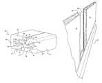
- FIG. 3is an environmental end view of the wall system including base/track supporting molding and a selected panel with wall joiner edge extrusion;
- FIG. 4is a rotated perspective of the system of FIG. 3 depicting first and second panels with opposing wall joiner edge extrusions arrayed in partially spaced fashion;
- FIG. 5is a perspective of first and second wall joiner edge extrusions detached from their respective panels and better depicting their interlocking configuration
- FIG. 6is a further detail perspective of a single extrusion
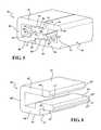
- FIGS. 7 and 8are additional rotated perspectives of the environmental views also depicted in FIGS. 3 and 4 ;
- FIG. 8Ais a cutaway perspective along line 8 A- 8 A of FIG. 8 and depicting the manner in which the extrusions are configured within opposite extending joiner edges of the individual panel sections, these further exhibiting first outer and harder plastic skins in combination with foam/insulating interiors;
- FIG. 9is an illustration of a top cap which can be affixed upon a continuous upper edge established by the interconnected and track supported panels;
- FIG. 10is an illustration of a corner molding for establishing an angled corner profile between succeeding panels
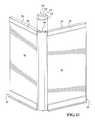
- FIG. 11is a partially exploded view of a further embodiment of the modular wall system integrating an arcuate corner with a likewise arcuate corner cap;
- FIG. 12is an enlarged and reduced length perspective of the corner interconnecting portion in use with first and second generally perpendicular arranged wall sections;
- FIG. 13is a top plan view of the wall corner engaged with the wall joiner edge extrusions.
- the present inventiondiscloses a wall system, such as in one embodiment being a free standing structure erected within an open building interior.
- the systemincorporates a plurality of polymeric based and foam filled panels, these integrating side edge extending and inter-engageable, typically rigid PVC, extrusions. Bottom edges of the panels are supported upon a track configured base molding, a separate top cap attaching along an upper continuous edge established by the interlocking panels.
- FIG. 1an environmental view is generally shown at 10 of the modular wall system according to one non-limiting embodiment of the present inventions.
- the kit and systemincludes any number of panels, see at 12 and 14 , which are joined together along common opposing edges, further at 16 and 18 .
- a base supporting track 20is provided and includes a lengthwise extending channel recess which supported bottom extending and interconnecting edges (not shown) of the panels.
- FIG. 2is an enlarged cross section of a selected track section 20 for supporting an extending bottom edge of the interconnected panels.
- the track section 20may be constructed of a rigid PVC (poly vinyl chloride) or other suitable material and includes a base or floor support surface 22 , from which upwardly extend first 24 and second 26 spaced apart walls.
- the inside opposing surfaces of the walls 24 and 26 and the interconnecting upper surfaces of the floor support 22collectively define a generally rectangular shaped pocket 28 for seating and supporting the bottom and bottom proximate sides of each panel in upstanding fashion.
- the cross sectional depiction of the floor support 22can include opposite extending profile edge contours, see arcuate at 30 and flattened at 32 .
- the uppermost edges of the walls 24 and 26may also exhibit variously notched or angled edge profiles, at 34 and 36 respectively, and which can include any variation of a lead-in angle or profile to facilitate vertical insertion and subsequent mounting support of the panels 12 , 14 , et seq.
- FIG. 3is an environmental end view of the wall system, again including the base/track supporting molding 22 and a selected panel 12 with a first wall joiner edge profile or extrusion 38 .
- FIG. 4is a rotated perspective of the system of FIG. 3 , again depicting the first 12 and second 14 panels with opposing wall joiner edge profiles or extrusions, such as again shown at 38 as well as at 40 , these being arrayed in partially spaced fashion.
- FIGS. 7 and 8are additional rotated perspectives of the environmental views also depicted in FIGS. 3 and 4 .
- FIG. 5is a cross sectional perspective in reduced length of the first 38 and second 40 wall joiner edge extrusions, detached from their respective panels 12 and 14 and better depicting their interlocking configuration.
- the wall joiner profiles 38 and 40are each constructed of a rigid PVC or other suitable material and, without limitation, can also include a lightweight metal or other metal exhibiting the necessary properties of durability or resilience.
- the term “extrusion” in reference to the joiner edge profiles 38 and 40is intended to denote one preferred embodiment for forming an elongated (such as again rigid PVC) material which is integrated or otherwise joined with the panel construction (see FIG. 8A ).
- other modificationsmay include the pluralities of panels, such as representatively shown at 12 and 14 , being reconfigured so that they may be injection molded or otherwise casted of a solid or other combination of materials not limited to those shown, and such as further which may contemplate the pairs of opposite edge extending profiles 38 and 40 being formed by other than an extrusion process, and such as being cast as one piece with the panel construction.
- each extrusionincludes an outer three sided configuration with a longer outer side (at 42 for extrusion profile 38 and at 44 for extrusion profile 40 ), a shorter spaced apart outer side (at 46 for extrusion 38 and at 48 for extrusion 40 ), and an interconnecting inner or back surface (at 50 for extrusion 38 and at 52 for extrusion 40 ).
- the mating configuration associated with the extrusions 38 and 40is established by inner stepped and outwardly projecting portions (at 54 for extrusion 38 and at 56 for extrusion 40 ).
- the projecting portions 54 and 56are inwardly stepped from the shorter outer sides 46 and 48 of the respective extrusions 38 and 40 , such that the shorter sides and inwardly stepped projecting portions respectively establish outwardly facing engagement ledges for receiving the outermost extending portions of the longer sides 42 and 44 .
- the extrusionsare reversed or mirrored in the manner shown to provide overlapping channel engagement and so that the projecting portions 54 and 56 abut one another along opposing inner surfaces ( 58 and 60 ), concurrent with the outermost end and inside end proximate surfaces of the longer sides 42 and 44 (see additional pairs of locations at 62 / 64 and 66 / 68 respectively) overlapping the inner projecting portions 54 and 56 (along opposing inwardly stepped surfaces 51 and 53 ) and engaging the abutment ledges (such further referenced by inwardly stepped end walls 70 / 72 ) defining the inwardly stepped transition between the shorter outer walls 46 and 48 and the inner projecting portions 54 and 56 .
- the inner stepped and outwardly projecting portions 54 and 56can further include angled end surface profiles, see central end surface 55 and adjoining upper 55 ′ and lower 55 ′′ surfaces for portion 54 .
- the end profile of outwardly projecting portion 56is characterized by central end surface 57 and adjoining upper 57 ′ and lower 57 ′′ surfaces.
- FIG. 6is a further detail perspective of a single extrusion, at 38 ′, similar to that depicted in FIG. 5 and more clearly illustrating the various surfaces (these being similarly referenced as compared to FIG. 5 ) associated with the mirroring and mating configuration.
- additional contoured edge locationssuch as 63 ′ associated with an underside angled surface adjoining face 62 ′ and underside 64 ′ is also depicted, with the angled end profile (surface 57 , 57 ′ and 57 ′′) for inwardly stepped and outwardly projecting portion 54 ′ repeated from that depicted in FIG. 5 .
- the interlocking configuration of the profile extrusions shown in FIGS. 5-6can be varied without limitation and in order to achieve a desired frictional and secure inter-fitting relationship between the extrusions and associated panels to which they are mounted in edge extending fashion.
- FIG. 8Aa cutaway perspective along line 8 A- 8 A of FIG. 8 and depicting the manner in which the extrusions 38 and 40 are configured within opposite extending joiner edges of the individual panel sections 12 and 14 .
- the panels 12 and 14according to the non-limiting construction shown, can each further exhibit first outer and harder plastic skins, such as which is shown at 74 and 76 for panel 12 , and further at 78 and 80 for panel 14 in combination with the provision of expanded foam/insulating interiors 82 and 84 .
- Each of the panels 12 and 14further depict a pair of extrusions 38 and 40 configured along their opposite joiner edges in the manner shown to assist in establishing a friction fit inter-assembly of any plurality of the panels in a continuously extending and supported fashion upon the base track 22 .
- the outer planar surfaces of the extrusion(further represented by surfaces 79 and 81 for extrusion 38 ′ in FIG. 6 , are depicted in FIG. 8A as bonded directly to the inside surfaces of the harder outer layers 74 / 76 of the selected panel section 12 .
- the panel outer layers 74 / 76 (panel 12 ) and 78 / 80 (panel 14 )are irregular to compensate for the cross sectional profile of the extrusions and further so that the assembled panels exhibit an abutting seam 83 .
- additional panelsmay include varying planar dimensions (e.g. along its length and/or height) and the present system further contemplates any combination of panels having planar and/or angled and interconnected sides (not shown) along with corresponding multi-sided and outline establishing bottom tracks and top caps (see FIG. 9 ).
- extrusions 38 and 40are capable of being produced in a molding or extruding operation along with the individual panels, such further not being limited to that shown. Additional envisioned applications include the extrusions being made from other materials and/or post applied to the edges of the panels.
- FIG. 9is an illustration of a top cap, such having a generally “U” shaped cross sectional profile with a base 86 and interconnecting and parallel spaced outer walls 88 and 90 , which can be affixed upon a continuous upper edge established by the interconnected and track supported panels 12 and 14 .
- an exterior profile associated with the walls 88 and 90may exhibit angled or tapered upper ends, at 92 and 94 , such providing fit and finish aspects when secured over the interconnected top edges of the panels.
- the capscan be constructed of a rigid PVC or other suitable material.
- FIG. 10an illustration is shown of an interfacing connection between a side extending extrusion (see such as previously as shown at 38 ′) in combination with a corner molding, such further being constructed of a similar material to that associated with the side extending extrusions, bottom track and top cap.
- the corner moldingtypically exhibits a curved central body 96 terminating at opposite ends in an inwardly stepped engaging portion (see further inwardly stepped and opposite ninety degree end most straight portions 98 and 100 extending respectively from opposite end walls 102 and 104 which interface between the curved ends of the central body 96 and the engaging end portions 98 / 100 ).
- the end portions 98 and 100are angularly offset such as at 90° as reflected by angle 106 taken between x and y axes taken through center lines associated with the end portions 98 and 100 .
- the end portions 98 / 100are dimensioned to fit between the opposing inner surface locations (see at 58 ′ and 64 ′ in FIG. 6 ) associated with the lateral receiving edge of the selected extrusion 38 ′.
- FIG. 11a partially exploded view is depicted of a variant, generally at 106 , of a curved corner interconnecting portion, defined as any of an extrusion or molding, according to a further embodiment of the modular wall system for integrating an arcuate corner between a pair of angled panels 12 and 14 .
- the panels 12 and 14are arranged in a non-limiting 90 degree angular orientation and are further supported upon bottom track supporting sections 20 as well as having top supported caps (see upper 86 and outer 88 ) interconnected walls.
- the corner molding 106is functionally similar to that depicted previously in FIG. 9 and includes a curved outer layer 108 (compare to 96 in FIG. 10 ) terminating at opposite ends in an inwardly stepped engaging portion (see further inwardly stepped and opposite ninety degree end most straight portions 110 and 112 which compare to 98 and 100 of FIG. 9 and which extend respectively from opposite end walls 114 and 116 , as further compared to at 102 and 104 ) and which interface between the curved ends of the central outer layer 108 and the engaging end portions 110 and 112 ).
- the three dimensional and cross sectional design of the arcuate corner molding 106is further exhibited by an inner curved layer 118 which is spatially arrayed relative to and interconnected with the outer layer 108 via an interconnecting web 120 .
- the inner curved layer 118is further exhibited by end proximate support surfaces, see at 122 and 124 as best shown in FIGS. 12-13 .
- the mounting arrangement of the edge extending extrusions 38 and 40 relative to the panel extending edgesis modified from that depicted in FIG. 8A (as well as understood to apply to the initially disclosed curved mounting relationship of FIG. 10 ).
- the extrusions 38 and 40 in FIG. 13are reconfigured to seat deeper within the side extending edges of the panels.
- the surface 79abuts flush with an edge of a first inside surface 126 of the panel whereas the opposite surface 81 is retracted inwardly from an edge of an opposing second inside surface 128 of selected panel 12 .
- the stepped end portions 110 and 112 of the outer curved layer 108frictionally fit or bias against the inside surface of the longer side 42 or 44 of the given extrusion, with the inwardly spaced and arcuate extending end surfaces 122 and 124 of the inner layer 118 likewise abutting against the second inside edge proximate surfaces (see again at 128 in FIG. 13 for selected panel 12 ).
- the curved fitting 106Upon installation, the curved fitting 106 provides three dimensional support along outer and inner curved layers, as compared to that associated with the example 96 of FIG. 10 , in order to array the panels 12 and 14 in a ninety degree or other possible orientation.
- the cutaway configuration of the panels 12 and 14can include any of those depicted in FIGS. 8A or 13 and which may include an extruded or injection molded notch or recess along its opposite extending sides into which the extrusions are concurrently formed or subsequently installed.
- the side edge projecting profiles (e.g. extrusions 38 / 40 ) in this variantare not alternating as compared to the arrangement of FIGS. 5 and 8A , rather they are mirrored as shown in extending fashion along the opposing edges of the panels 12 and 14 for engagement by the three dimensional variant 106 of the arcuate corner interconnecting portion as previously described.
- the opposing arrangement of extrusions 38 / 40can be reconfigured as shown in FIG. 8A concurrent with modifying the corner portion 106 such that the opposite curved ends are reversed in configuration.
- a corner top cap 130can be provided which seats over the three dimensional corner molding 106 .
- the corner top cap 130includes a top surface 132 with interconnecting front 134 and rear 136 surfaces which fit over the exposed top of the corner molding 106 in seam abutting fashion with the linear top caps 86 secured atop the panels 12 , 14 , et seq.
- edge joiner extrusions 38 and 40being reconfigured in any manner desired beyond that shown and in order to provide an adequate friction inducing and mating engagement between the joiner edges of the panels.
Landscapes
- Engineering & Computer Science (AREA)
- Architecture (AREA)
- Physics & Mathematics (AREA)
- Electromagnetism (AREA)
- Civil Engineering (AREA)
- Structural Engineering (AREA)
- Finishing Walls (AREA)
Abstract
Description
Claims (9)
Priority Applications (1)
| Application Number | Priority Date | Filing Date | Title |
|---|---|---|---|
| US15/015,181US9617731B2 (en) | 2015-06-04 | 2016-02-04 | Modular wall system and kit incorporating extruded end interlocking portions in addition to base support track molding and attachable top cap |
Applications Claiming Priority (2)
| Application Number | Priority Date | Filing Date | Title |
|---|---|---|---|
| US201562171089P | 2015-06-04 | 2015-06-04 | |
| US15/015,181US9617731B2 (en) | 2015-06-04 | 2016-02-04 | Modular wall system and kit incorporating extruded end interlocking portions in addition to base support track molding and attachable top cap |
Publications (2)
| Publication Number | Publication Date |
|---|---|
| US20160356037A1 US20160356037A1 (en) | 2016-12-08 |
| US9617731B2true US9617731B2 (en) | 2017-04-11 |
Family
ID=57451819
Family Applications (1)
| Application Number | Title | Priority Date | Filing Date |
|---|---|---|---|
| US15/015,181Expired - Fee RelatedUS9617731B2 (en) | 2015-06-04 | 2016-02-04 | Modular wall system and kit incorporating extruded end interlocking portions in addition to base support track molding and attachable top cap |
Country Status (1)
| Country | Link |
|---|---|
| US (1) | US9617731B2 (en) |
Cited By (2)
| Publication number | Priority date | Publication date | Assignee | Title |
|---|---|---|---|---|
| US11459751B2 (en)* | 2017-07-12 | 2022-10-04 | Dirtt Environmental Solutions Ltd | Wall seal |
| US20240263447A1 (en)* | 2023-02-03 | 2024-08-08 | Cover Technologies, Inc. | Exterior building augmentation system |
Families Citing this family (1)
| Publication number | Priority date | Publication date | Assignee | Title |
|---|---|---|---|---|
| US12163330B2 (en)* | 2022-09-25 | 2024-12-10 | Signature Wall Solutions, Inc. | Locking edge joiner system for a temporary wall system |
Citations (28)
| Publication number | Priority date | Publication date | Assignee | Title |
|---|---|---|---|---|
| GB287247A (en) | 1926-12-20 | 1928-03-20 | Sydney Frederick Corby | Improvements in or relating to partition walls |
| US3367076A (en)* | 1965-09-22 | 1968-02-06 | Soule Steel Company | Wall panel construction |
| US3765135A (en)* | 1972-02-08 | 1973-10-16 | J Gerhardt | Oven wall and panel therefor |
| US3789567A (en)* | 1972-12-29 | 1974-02-05 | American Standard Inc | Edge seals for multiple-interfitting partitions |
| US3828502A (en)* | 1972-09-08 | 1974-08-13 | Phelps Dodge Ind Inc | Modular wall section for buildings |
| US4037377A (en)* | 1968-05-28 | 1977-07-26 | H. H. Robertson Company | Foamed-in-place double-skin building panel |
| US4107892A (en)* | 1977-07-27 | 1978-08-22 | Butler Manufacturing Company | Wall panel unit |
| US4703985A (en)* | 1985-02-07 | 1987-11-03 | Haworth, Inc. | Raceway for curved wall panel |
| US4744185A (en)* | 1985-01-22 | 1988-05-17 | Philippe Lamberet | Edge profile for insulating panel |
| US4835921A (en)* | 1988-07-01 | 1989-06-06 | Molex Incorporated | Raceway frame and method for curved modular wall panel |
| US4866891A (en)* | 1987-11-16 | 1989-09-19 | Young Rubber Company | Permanent non-removable insulating type concrete wall forming structure |
| WO1990004073A1 (en) | 1988-10-07 | 1990-04-19 | Chelsea Revival Pty. Ltd. | Modular panelling system |
| US5305567A (en)* | 1990-12-19 | 1994-04-26 | Wittler Waldemar E | Interlocking structural members with edge connectors |
| US5325649A (en)* | 1992-07-07 | 1994-07-05 | Nikken Seattle, Inc. | Easily-assembled housing structure and connectors thereof |
| WO1994028262A2 (en) | 1993-05-28 | 1994-12-08 | Royal Building Systems (Cdn) Limited | Thermoplastic structural components and structures formed therefrom |
| EP0814214A2 (en) | 1996-06-20 | 1997-12-29 | Plamet Limited Liability Company | System of structural elements, particularly for building internal walls |
| US6006480A (en) | 1997-06-27 | 1999-12-28 | Rook; John G. | Low cost prefabricated housing construction system |
| US6256960B1 (en)* | 1999-04-12 | 2001-07-10 | Frank J. Babcock | Modular building construction and components thereof |
| US7127865B2 (en)* | 2002-10-11 | 2006-10-31 | Douglas Robert B | Modular structure for building panels and methods of making and using same |
| GB2427628A (en) | 2004-03-03 | 2007-01-03 | Floor 2 Wall Ltd | Improvements in or relating to wall systems |
| US7373762B2 (en) | 2003-06-02 | 2008-05-20 | Hubbard Richard L | Multi-functional assembly including a panel and stud with oppositely configured “V” notches along a cross sectional configuration |
| WO2010080072A2 (en) | 2009-01-06 | 2010-07-15 | Noah Samuel Vedanaigam | An extruded section and structures made using the extruded section |
| US7900411B2 (en)* | 2006-02-17 | 2011-03-08 | Antonic James P | Shear wall building assemblies |
| WO2011141591A1 (en) | 2010-05-10 | 2011-11-17 | Munoz Saiz Manuel | Modular construction system for walls, partitions, enclosures or similar |
| US8429858B1 (en) | 2009-01-23 | 2013-04-30 | Markus F. Robinson | Semi-permanent, 4-season, modular, extruded plastic, flat panel, insulatable, portable, low-cost, rigid-walled structure |
| US20130199118A1 (en) | 2010-10-22 | 2013-08-08 | Syma Intercontinental Ag | Frame profile system |
| US8707648B2 (en) | 2005-04-08 | 2014-04-29 | Fry Reglet Corporation | Retainer and panel with insert for installing wall covering panels |
| US8997436B2 (en)* | 2012-05-18 | 2015-04-07 | Douglas B. Spear | Wall panel system |
- 2016
- 2016-02-04USUS15/015,181patent/US9617731B2/ennot_activeExpired - Fee Related
Patent Citations (28)
| Publication number | Priority date | Publication date | Assignee | Title |
|---|---|---|---|---|
| GB287247A (en) | 1926-12-20 | 1928-03-20 | Sydney Frederick Corby | Improvements in or relating to partition walls |
| US3367076A (en)* | 1965-09-22 | 1968-02-06 | Soule Steel Company | Wall panel construction |
| US4037377A (en)* | 1968-05-28 | 1977-07-26 | H. H. Robertson Company | Foamed-in-place double-skin building panel |
| US3765135A (en)* | 1972-02-08 | 1973-10-16 | J Gerhardt | Oven wall and panel therefor |
| US3828502A (en)* | 1972-09-08 | 1974-08-13 | Phelps Dodge Ind Inc | Modular wall section for buildings |
| US3789567A (en)* | 1972-12-29 | 1974-02-05 | American Standard Inc | Edge seals for multiple-interfitting partitions |
| US4107892A (en)* | 1977-07-27 | 1978-08-22 | Butler Manufacturing Company | Wall panel unit |
| US4744185A (en)* | 1985-01-22 | 1988-05-17 | Philippe Lamberet | Edge profile for insulating panel |
| US4703985A (en)* | 1985-02-07 | 1987-11-03 | Haworth, Inc. | Raceway for curved wall panel |
| US4866891A (en)* | 1987-11-16 | 1989-09-19 | Young Rubber Company | Permanent non-removable insulating type concrete wall forming structure |
| US4835921A (en)* | 1988-07-01 | 1989-06-06 | Molex Incorporated | Raceway frame and method for curved modular wall panel |
| WO1990004073A1 (en) | 1988-10-07 | 1990-04-19 | Chelsea Revival Pty. Ltd. | Modular panelling system |
| US5305567A (en)* | 1990-12-19 | 1994-04-26 | Wittler Waldemar E | Interlocking structural members with edge connectors |
| US5325649A (en)* | 1992-07-07 | 1994-07-05 | Nikken Seattle, Inc. | Easily-assembled housing structure and connectors thereof |
| WO1994028262A2 (en) | 1993-05-28 | 1994-12-08 | Royal Building Systems (Cdn) Limited | Thermoplastic structural components and structures formed therefrom |
| EP0814214A2 (en) | 1996-06-20 | 1997-12-29 | Plamet Limited Liability Company | System of structural elements, particularly for building internal walls |
| US6006480A (en) | 1997-06-27 | 1999-12-28 | Rook; John G. | Low cost prefabricated housing construction system |
| US6256960B1 (en)* | 1999-04-12 | 2001-07-10 | Frank J. Babcock | Modular building construction and components thereof |
| US7127865B2 (en)* | 2002-10-11 | 2006-10-31 | Douglas Robert B | Modular structure for building panels and methods of making and using same |
| US7373762B2 (en) | 2003-06-02 | 2008-05-20 | Hubbard Richard L | Multi-functional assembly including a panel and stud with oppositely configured “V” notches along a cross sectional configuration |
| GB2427628A (en) | 2004-03-03 | 2007-01-03 | Floor 2 Wall Ltd | Improvements in or relating to wall systems |
| US8707648B2 (en) | 2005-04-08 | 2014-04-29 | Fry Reglet Corporation | Retainer and panel with insert for installing wall covering panels |
| US7900411B2 (en)* | 2006-02-17 | 2011-03-08 | Antonic James P | Shear wall building assemblies |
| WO2010080072A2 (en) | 2009-01-06 | 2010-07-15 | Noah Samuel Vedanaigam | An extruded section and structures made using the extruded section |
| US8429858B1 (en) | 2009-01-23 | 2013-04-30 | Markus F. Robinson | Semi-permanent, 4-season, modular, extruded plastic, flat panel, insulatable, portable, low-cost, rigid-walled structure |
| WO2011141591A1 (en) | 2010-05-10 | 2011-11-17 | Munoz Saiz Manuel | Modular construction system for walls, partitions, enclosures or similar |
| US20130199118A1 (en) | 2010-10-22 | 2013-08-08 | Syma Intercontinental Ag | Frame profile system |
| US8997436B2 (en)* | 2012-05-18 | 2015-04-07 | Douglas B. Spear | Wall panel system |
Cited By (2)
| Publication number | Priority date | Publication date | Assignee | Title |
|---|---|---|---|---|
| US11459751B2 (en)* | 2017-07-12 | 2022-10-04 | Dirtt Environmental Solutions Ltd | Wall seal |
| US20240263447A1 (en)* | 2023-02-03 | 2024-08-08 | Cover Technologies, Inc. | Exterior building augmentation system |
Also Published As
| Publication number | Publication date |
|---|---|
| US20160356037A1 (en) | 2016-12-08 |
Similar Documents
| Publication | Publication Date | Title |
|---|---|---|
| US6719277B2 (en) | Thermoformed wall and fencing assemblies | |
| US6792727B2 (en) | Curved wall panel system | |
| US8584417B1 (en) | Wall panel system | |
| US9617731B2 (en) | Modular wall system and kit incorporating extruded end interlocking portions in addition to base support track molding and attachable top cap | |
| ES2327502T5 (en) | Floor boards | |
| CA2644220C (en) | Profiled rail system | |
| US20110185670A1 (en) | Interlocking panel system | |
| US20060113517A1 (en) | Modular fencing system and method for constructing same | |
| US7966686B2 (en) | Support structure for car wash components | |
| ATE330787T1 (en) | FOAMED PLASTIC BOARD | |
| US20070181865A1 (en) | Pickets for use in modular fence systems | |
| US20180195281A1 (en) | Construction block, a wall structure comprising the same, and a method for manufacture of said construction block and of said wall structure | |
| WO2006017582A3 (en) | Roof and wall covering with improved corner construction | |
| AU2007321752B2 (en) | A sideform system | |
| EP2078121A1 (en) | Thermal insulating composite panel, method of its production and building structures from such panels | |
| US20240360666A1 (en) | Connecting members and system for modular wall junctions | |
| JP2006511745A (en) | Wall structure using hollow glass building materials | |
| CA3002936C (en) | Insulating panels for framed cavities in buildings | |
| US20140021423A1 (en) | Decorative railing assembly | |
| US20230323662A1 (en) | Connecting members and system for modular wall junctions | |
| EP3913160B1 (en) | An acoustic modular segment and an assembly of acoustic modular segments | |
| US7536973B2 (en) | Plastic blow molded board-like members | |
| KR101533077B1 (en) | Precast structure of sandwiches panels for on the wall | |
| JP6914222B2 (en) | Casing frame material, mounting structure and mounting method of casing frame material | |
| RU95005U1 (en) | CONSTRUCTION OF WALLS FROM THREE-LAYER PANELS WITH FILLER FROM POLYURETHANE |
Legal Events
| Date | Code | Title | Description |
|---|---|---|---|
| AS | Assignment | Owner name:U.S. FARATHANE CORPORATION, MICHIGAN Free format text:ASSIGNMENT OF ASSIGNORS INTEREST;ASSIGNORS:BAXTER, KEVIN CHARLES;PARPART, DAVID BRIAN;REEL/FRAME:037661/0090 Effective date:20160128 | |
| STCF | Information on status: patent grant | Free format text:PATENTED CASE | |
| MAFP | Maintenance fee payment | Free format text:PAYMENT OF MAINTENANCE FEE, 4TH YEAR, LARGE ENTITY (ORIGINAL EVENT CODE: M1551); ENTITY STATUS OF PATENT OWNER: LARGE ENTITY Year of fee payment:4 | |
| AS | Assignment | Owner name:U.S. FARATHANE, LLC, MICHIGAN Free format text:ASSIGNMENT OF ASSIGNORS INTEREST;ASSIGNOR:U.S. FARATHANE CORPORATION;REEL/FRAME:055767/0519 Effective date:20210329 | |
| AS | Assignment | Owner name:BANK OF AMERICA, N.A., MICHIGAN Free format text:ABL SECURITY AGREEMENT;ASSIGNOR:U.S. FARATHANE, LLC;REEL/FRAME:055845/0928 Effective date:20210406 Owner name:BANK OF AMERICA, N.A., NORTH CAROLINA Free format text:TERM LOAN SECURITY AGREEMENT;ASSIGNOR:U.S. FARATHANE, LLC;REEL/FRAME:055846/0028 Effective date:20210406 | |
| AS | Assignment | Owner name:TMI TRUST COMPANY, AS AGENT, GEORGIA Free format text:SECURITY INTEREST;ASSIGNOR:U.S. FARATHANE, LLC;REEL/FRAME:055857/0173 Effective date:20210406 | |
| AS | Assignment | Owner name:CHEMCAST, LLC, MICHIGAN Free format text:RELEASE OF SECURITY INTEREST IN INTELLECTUAL PROPERTY;ASSIGNOR:BANK OF AMERICA, N.A.;REEL/FRAME:063985/0064 Effective date:20230612 Owner name:U.S. FARATHANE, LLC, MICHIGAN Free format text:RELEASE OF SECURITY INTEREST IN INTELLECTUAL PROPERTY;ASSIGNOR:BANK OF AMERICA, N.A.;REEL/FRAME:063985/0064 Effective date:20230612 Owner name:U.S. FARATHANE, LLC, MICHIGAN Free format text:TERMINATION AND RELEASE OF SECURITY INTEREST IN INTELLECTUAL PROPERTY;ASSIGNOR:TMI TRUST COMPANY, AS AGENT;REEL/FRAME:063984/0504 Effective date:20230612 | |
| AS | Assignment | Owner name:CHEMCAST, LLC, MICHIGAN Free format text:RELEASE OF PATENT SECURITY INTERESTS (ABL);ASSIGNOR:BANK OF AMERICA, N.A.;REEL/FRAME:067490/0072 Effective date:20240520 Owner name:U.S. FARATHANE, LLC, MICHIGAN Free format text:RELEASE OF PATENT SECURITY INTERESTS (ABL);ASSIGNOR:BANK OF AMERICA, N.A.;REEL/FRAME:067490/0072 Effective date:20240520 Owner name:FIFTH THIRD BANK, NATIONAL ASSOCIATION, DISTRICT OF COLUMBIA Free format text:INTELLECTUAL PROPERTY SECURITY AGREEMENT;ASSIGNOR:U.S. FARATHANE, LLC;REEL/FRAME:067501/0539 Effective date:20240521 | |
| FEPP | Fee payment procedure | Free format text:MAINTENANCE FEE REMINDER MAILED (ORIGINAL EVENT CODE: REM.); ENTITY STATUS OF PATENT OWNER: LARGE ENTITY | |
| LAPS | Lapse for failure to pay maintenance fees | Free format text:PATENT EXPIRED FOR FAILURE TO PAY MAINTENANCE FEES (ORIGINAL EVENT CODE: EXP.); ENTITY STATUS OF PATENT OWNER: LARGE ENTITY | |
| STCH | Information on status: patent discontinuation | Free format text:PATENT EXPIRED DUE TO NONPAYMENT OF MAINTENANCE FEES UNDER 37 CFR 1.362 | |
| FP | Lapsed due to failure to pay maintenance fee | Effective date:20250411 |