US9617029B2 - Lightweight container base - Google Patents
Lightweight container baseDownload PDFInfo
- Publication number
- US9617029B2 US9617029B2US14/238,795US201214238795AUS9617029B2US 9617029 B2US9617029 B2US 9617029B2US 201214238795 AUS201214238795 AUS 201214238795AUS 9617029 B2US9617029 B2US 9617029B2
- Authority
- US
- United States
- Prior art keywords
- container
- longitudinal axis
- strap
- straps
- sidewall
- Prior art date
- Legal status (The legal status is an assumption and is not a legal conclusion. Google has not performed a legal analysis and makes no representation as to the accuracy of the status listed.)
- Active, expires
Links
Images


Classifications
- B—PERFORMING OPERATIONS; TRANSPORTING
- B65—CONVEYING; PACKING; STORING; HANDLING THIN OR FILAMENTARY MATERIAL
- B65D—CONTAINERS FOR STORAGE OR TRANSPORT OF ARTICLES OR MATERIALS, e.g. BAGS, BARRELS, BOTTLES, BOXES, CANS, CARTONS, CRATES, DRUMS, JARS, TANKS, HOPPERS, FORWARDING CONTAINERS; ACCESSORIES, CLOSURES, OR FITTINGS THEREFOR; PACKAGING ELEMENTS; PACKAGES
- B65D1/00—Rigid or semi-rigid containers having bodies formed in one piece, e.g. by casting metallic material, by moulding plastics, by blowing vitreous material, by throwing ceramic material, by moulding pulped fibrous material or by deep-drawing operations performed on sheet material
- B65D1/02—Bottles or similar containers with necks or like restricted apertures, designed for pouring contents
- B65D1/0223—Bottles or similar containers with necks or like restricted apertures, designed for pouring contents characterised by shape
- B65D1/0261—Bottom construction
- B65D1/0284—Bottom construction having a discontinuous contact surface, e.g. discrete feet
- B—PERFORMING OPERATIONS; TRANSPORTING
- B29—WORKING OF PLASTICS; WORKING OF SUBSTANCES IN A PLASTIC STATE IN GENERAL
- B29C—SHAPING OR JOINING OF PLASTICS; SHAPING OF MATERIAL IN A PLASTIC STATE, NOT OTHERWISE PROVIDED FOR; AFTER-TREATMENT OF THE SHAPED PRODUCTS, e.g. REPAIRING
- B29C49/00—Blow-moulding, i.e. blowing a preform or parison to a desired shape within a mould; Apparatus therefor
- B29C49/0005—Blow-moulding, i.e. blowing a preform or parison to a desired shape within a mould; Apparatus therefor characterised by the material
- B—PERFORMING OPERATIONS; TRANSPORTING
- B29—WORKING OF PLASTICS; WORKING OF SUBSTANCES IN A PLASTIC STATE IN GENERAL
- B29C—SHAPING OR JOINING OF PLASTICS; SHAPING OF MATERIAL IN A PLASTIC STATE, NOT OTHERWISE PROVIDED FOR; AFTER-TREATMENT OF THE SHAPED PRODUCTS, e.g. REPAIRING
- B29C49/00—Blow-moulding, i.e. blowing a preform or parison to a desired shape within a mould; Apparatus therefor
- B29C49/08—Biaxial stretching during blow-moulding
- B29C49/10—Biaxial stretching during blow-moulding using mechanical means for prestretching
- B29C49/12—Stretching rods
- B—PERFORMING OPERATIONS; TRANSPORTING
- B29—WORKING OF PLASTICS; WORKING OF SUBSTANCES IN A PLASTIC STATE IN GENERAL
- B29C—SHAPING OR JOINING OF PLASTICS; SHAPING OF MATERIAL IN A PLASTIC STATE, NOT OTHERWISE PROVIDED FOR; AFTER-TREATMENT OF THE SHAPED PRODUCTS, e.g. REPAIRING
- B29C49/00—Blow-moulding, i.e. blowing a preform or parison to a desired shape within a mould; Apparatus therefor
- B29C49/42—Component parts, details or accessories; Auxiliary operations
- B29C49/48—Moulds
- B29C49/4823—Moulds with incorporated heating or cooling means
- B—PERFORMING OPERATIONS; TRANSPORTING
- B29—WORKING OF PLASTICS; WORKING OF SUBSTANCES IN A PLASTIC STATE IN GENERAL
- B29C—SHAPING OR JOINING OF PLASTICS; SHAPING OF MATERIAL IN A PLASTIC STATE, NOT OTHERWISE PROVIDED FOR; AFTER-TREATMENT OF THE SHAPED PRODUCTS, e.g. REPAIRING
- B29C49/00—Blow-moulding, i.e. blowing a preform or parison to a desired shape within a mould; Apparatus therefor
- B29C49/42—Component parts, details or accessories; Auxiliary operations
- B29C49/48—Moulds
- B29C49/54—Moulds for undercut articles
- B29C49/541—Moulds for undercut articles having a recessed undersurface
- B—PERFORMING OPERATIONS; TRANSPORTING
- B29—WORKING OF PLASTICS; WORKING OF SUBSTANCES IN A PLASTIC STATE IN GENERAL
- B29D—PRODUCING PARTICULAR ARTICLES FROM PLASTICS OR FROM SUBSTANCES IN A PLASTIC STATE
- B29D22/00—Producing hollow articles
- B29D22/003—Containers for packaging, storing or transporting, e.g. bottles, jars, cans, barrels, tanks
- B—PERFORMING OPERATIONS; TRANSPORTING
- B65—CONVEYING; PACKING; STORING; HANDLING THIN OR FILAMENTARY MATERIAL
- B65D—CONTAINERS FOR STORAGE OR TRANSPORT OF ARTICLES OR MATERIALS, e.g. BAGS, BARRELS, BOTTLES, BOXES, CANS, CARTONS, CRATES, DRUMS, JARS, TANKS, HOPPERS, FORWARDING CONTAINERS; ACCESSORIES, CLOSURES, OR FITTINGS THEREFOR; PACKAGING ELEMENTS; PACKAGES
- B65D1/00—Rigid or semi-rigid containers having bodies formed in one piece, e.g. by casting metallic material, by moulding plastics, by blowing vitreous material, by throwing ceramic material, by moulding pulped fibrous material or by deep-drawing operations performed on sheet material
- B65D1/02—Bottles or similar containers with necks or like restricted apertures, designed for pouring contents
- B65D1/0223—Bottles or similar containers with necks or like restricted apertures, designed for pouring contents characterised by shape
- B65D1/023—Neck construction
- B65D1/0246—Closure retaining means, e.g. beads, screw-threads
- B—PERFORMING OPERATIONS; TRANSPORTING
- B65—CONVEYING; PACKING; STORING; HANDLING THIN OR FILAMENTARY MATERIAL
- B65D—CONTAINERS FOR STORAGE OR TRANSPORT OF ARTICLES OR MATERIALS, e.g. BAGS, BARRELS, BOTTLES, BOXES, CANS, CARTONS, CRATES, DRUMS, JARS, TANKS, HOPPERS, FORWARDING CONTAINERS; ACCESSORIES, CLOSURES, OR FITTINGS THEREFOR; PACKAGING ELEMENTS; PACKAGES
- B65D1/00—Rigid or semi-rigid containers having bodies formed in one piece, e.g. by casting metallic material, by moulding plastics, by blowing vitreous material, by throwing ceramic material, by moulding pulped fibrous material or by deep-drawing operations performed on sheet material
- B65D1/02—Bottles or similar containers with necks or like restricted apertures, designed for pouring contents
- B65D1/0223—Bottles or similar containers with necks or like restricted apertures, designed for pouring contents characterised by shape
- B65D1/0261—Bottom construction
- B—PERFORMING OPERATIONS; TRANSPORTING
- B65—CONVEYING; PACKING; STORING; HANDLING THIN OR FILAMENTARY MATERIAL
- B65D—CONTAINERS FOR STORAGE OR TRANSPORT OF ARTICLES OR MATERIALS, e.g. BAGS, BARRELS, BOTTLES, BOXES, CANS, CARTONS, CRATES, DRUMS, JARS, TANKS, HOPPERS, FORWARDING CONTAINERS; ACCESSORIES, CLOSURES, OR FITTINGS THEREFOR; PACKAGING ELEMENTS; PACKAGES
- B65D1/00—Rigid or semi-rigid containers having bodies formed in one piece, e.g. by casting metallic material, by moulding plastics, by blowing vitreous material, by throwing ceramic material, by moulding pulped fibrous material or by deep-drawing operations performed on sheet material
- B65D1/40—Details of walls
- B65D1/42—Reinforcing or strengthening parts or members
- B65D1/46—Local reinforcements, e.g. adjacent closures
- B—PERFORMING OPERATIONS; TRANSPORTING
- B65—CONVEYING; PACKING; STORING; HANDLING THIN OR FILAMENTARY MATERIAL
- B65D—CONTAINERS FOR STORAGE OR TRANSPORT OF ARTICLES OR MATERIALS, e.g. BAGS, BARRELS, BOTTLES, BOXES, CANS, CARTONS, CRATES, DRUMS, JARS, TANKS, HOPPERS, FORWARDING CONTAINERS; ACCESSORIES, CLOSURES, OR FITTINGS THEREFOR; PACKAGING ELEMENTS; PACKAGES
- B65D1/00—Rigid or semi-rigid containers having bodies formed in one piece, e.g. by casting metallic material, by moulding plastics, by blowing vitreous material, by throwing ceramic material, by moulding pulped fibrous material or by deep-drawing operations performed on sheet material
- B65D1/40—Details of walls
- B65D1/42—Reinforcing or strengthening parts or members
- B65D1/48—Reinforcements of dissimilar materials, e.g. metal frames in plastic walls
- B—PERFORMING OPERATIONS; TRANSPORTING
- B65—CONVEYING; PACKING; STORING; HANDLING THIN OR FILAMENTARY MATERIAL
- B65D—CONTAINERS FOR STORAGE OR TRANSPORT OF ARTICLES OR MATERIALS, e.g. BAGS, BARRELS, BOTTLES, BOXES, CANS, CARTONS, CRATES, DRUMS, JARS, TANKS, HOPPERS, FORWARDING CONTAINERS; ACCESSORIES, CLOSURES, OR FITTINGS THEREFOR; PACKAGING ELEMENTS; PACKAGES
- B65D79/00—Kinds or details of packages, not otherwise provided for
- B65D79/005—Packages having deformable parts for indicating or neutralizing internal pressure-variations by other means than venting
- B65D79/008—Packages having deformable parts for indicating or neutralizing internal pressure-variations by other means than venting the deformable part being located in a rigid or semi-rigid container, e.g. in bottles or jars
- B65D79/0081—Packages having deformable parts for indicating or neutralizing internal pressure-variations by other means than venting the deformable part being located in a rigid or semi-rigid container, e.g. in bottles or jars in the bottom part thereof
- B—PERFORMING OPERATIONS; TRANSPORTING
- B65—CONVEYING; PACKING; STORING; HANDLING THIN OR FILAMENTARY MATERIAL
- B65D—CONTAINERS FOR STORAGE OR TRANSPORT OF ARTICLES OR MATERIALS, e.g. BAGS, BARRELS, BOTTLES, BOXES, CANS, CARTONS, CRATES, DRUMS, JARS, TANKS, HOPPERS, FORWARDING CONTAINERS; ACCESSORIES, CLOSURES, OR FITTINGS THEREFOR; PACKAGING ELEMENTS; PACKAGES
- B65D85/00—Containers, packaging elements or packages, specially adapted for particular articles or materials
- B65D85/70—Containers, packaging elements or packages, specially adapted for particular articles or materials for materials not otherwise provided for
- B—PERFORMING OPERATIONS; TRANSPORTING
- B29—WORKING OF PLASTICS; WORKING OF SUBSTANCES IN A PLASTIC STATE IN GENERAL
- B29C—SHAPING OR JOINING OF PLASTICS; SHAPING OF MATERIAL IN A PLASTIC STATE, NOT OTHERWISE PROVIDED FOR; AFTER-TREATMENT OF THE SHAPED PRODUCTS, e.g. REPAIRING
- B29C49/00—Blow-moulding, i.e. blowing a preform or parison to a desired shape within a mould; Apparatus therefor
- B29C49/42—Component parts, details or accessories; Auxiliary operations
- B29C49/48—Moulds
- B29C49/4802—Moulds with means for locally compressing part(s) of the parison in the main blowing cavity
- B29C2049/4807—Moulds with means for locally compressing part(s) of the parison in the main blowing cavity by movable mould parts in the mould halves
- B—PERFORMING OPERATIONS; TRANSPORTING
- B29—WORKING OF PLASTICS; WORKING OF SUBSTANCES IN A PLASTIC STATE IN GENERAL
- B29C—SHAPING OR JOINING OF PLASTICS; SHAPING OF MATERIAL IN A PLASTIC STATE, NOT OTHERWISE PROVIDED FOR; AFTER-TREATMENT OF THE SHAPED PRODUCTS, e.g. REPAIRING
- B29C49/00—Blow-moulding, i.e. blowing a preform or parison to a desired shape within a mould; Apparatus therefor
- B29C49/42—Component parts, details or accessories; Auxiliary operations
- B29C49/48—Moulds
- B29C49/4823—Moulds with incorporated heating or cooling means
- B29C2049/4838—Moulds with incorporated heating or cooling means for heating moulds or mould parts
- B29C2049/4846—Moulds with incorporated heating or cooling means for heating moulds or mould parts in different areas of the mould at different temperatures, e.g. neck, shoulder or bottom
- B29C2049/4848—Bottom
- B—PERFORMING OPERATIONS; TRANSPORTING
- B29—WORKING OF PLASTICS; WORKING OF SUBSTANCES IN A PLASTIC STATE IN GENERAL
- B29C—SHAPING OR JOINING OF PLASTICS; SHAPING OF MATERIAL IN A PLASTIC STATE, NOT OTHERWISE PROVIDED FOR; AFTER-TREATMENT OF THE SHAPED PRODUCTS, e.g. REPAIRING
- B29C49/00—Blow-moulding, i.e. blowing a preform or parison to a desired shape within a mould; Apparatus therefor
- B29C49/42—Component parts, details or accessories; Auxiliary operations
- B29C49/48—Moulds
- B29C49/4823—Moulds with incorporated heating or cooling means
- B29C2049/4838—Moulds with incorporated heating or cooling means for heating moulds or mould parts
- B29C2049/4846—Moulds with incorporated heating or cooling means for heating moulds or mould parts in different areas of the mould at different temperatures, e.g. neck, shoulder or bottom
- B29C2049/4851—Side walls
- B—PERFORMING OPERATIONS; TRANSPORTING
- B29—WORKING OF PLASTICS; WORKING OF SUBSTANCES IN A PLASTIC STATE IN GENERAL
- B29C—SHAPING OR JOINING OF PLASTICS; SHAPING OF MATERIAL IN A PLASTIC STATE, NOT OTHERWISE PROVIDED FOR; AFTER-TREATMENT OF THE SHAPED PRODUCTS, e.g. REPAIRING
- B29C2949/00—Indexing scheme relating to blow-moulding
- B29C2949/07—Preforms or parisons characterised by their configuration
- B29C2949/0715—Preforms or parisons characterised by their configuration the preform having one end closed
- B—PERFORMING OPERATIONS; TRANSPORTING
- B29—WORKING OF PLASTICS; WORKING OF SUBSTANCES IN A PLASTIC STATE IN GENERAL
- B29C—SHAPING OR JOINING OF PLASTICS; SHAPING OF MATERIAL IN A PLASTIC STATE, NOT OTHERWISE PROVIDED FOR; AFTER-TREATMENT OF THE SHAPED PRODUCTS, e.g. REPAIRING
- B29C49/00—Blow-moulding, i.e. blowing a preform or parison to a desired shape within a mould; Apparatus therefor
- B29C49/02—Combined blow-moulding and manufacture of the preform or the parison
- B29C49/06—Injection blow-moulding
- B—PERFORMING OPERATIONS; TRANSPORTING
- B29—WORKING OF PLASTICS; WORKING OF SUBSTANCES IN A PLASTIC STATE IN GENERAL
- B29C—SHAPING OR JOINING OF PLASTICS; SHAPING OF MATERIAL IN A PLASTIC STATE, NOT OTHERWISE PROVIDED FOR; AFTER-TREATMENT OF THE SHAPED PRODUCTS, e.g. REPAIRING
- B29C49/00—Blow-moulding, i.e. blowing a preform or parison to a desired shape within a mould; Apparatus therefor
- B29C49/08—Biaxial stretching during blow-moulding
- B29C49/10—Biaxial stretching during blow-moulding using mechanical means for prestretching
- B29C49/12—Stretching rods
- B29C49/121—Stretching rod configuration, e.g. geometry; Stretching rod material
- B—PERFORMING OPERATIONS; TRANSPORTING
- B29—WORKING OF PLASTICS; WORKING OF SUBSTANCES IN A PLASTIC STATE IN GENERAL
- B29K—INDEXING SCHEME ASSOCIATED WITH SUBCLASSES B29B, B29C OR B29D, RELATING TO MOULDING MATERIALS OR TO MATERIALS FOR MOULDS, REINFORCEMENTS, FILLERS OR PREFORMED PARTS, e.g. INSERTS
- B29K2067/00—Use of polyesters or derivatives thereof, as moulding material
- B29K2067/003—PET, i.e. poylethylene terephthalate
- B—PERFORMING OPERATIONS; TRANSPORTING
- B29—WORKING OF PLASTICS; WORKING OF SUBSTANCES IN A PLASTIC STATE IN GENERAL
- B29L—INDEXING SCHEME ASSOCIATED WITH SUBCLASS B29C, RELATING TO PARTICULAR ARTICLES
- B29L2031/00—Other particular articles
- B29L2031/712—Containers; Packaging elements or accessories, Packages
- B29L2031/7158—Bottles
- B—PERFORMING OPERATIONS; TRANSPORTING
- B65—CONVEYING; PACKING; STORING; HANDLING THIN OR FILAMENTARY MATERIAL
- B65D—CONTAINERS FOR STORAGE OR TRANSPORT OF ARTICLES OR MATERIALS, e.g. BAGS, BARRELS, BOTTLES, BOXES, CANS, CARTONS, CRATES, DRUMS, JARS, TANKS, HOPPERS, FORWARDING CONTAINERS; ACCESSORIES, CLOSURES, OR FITTINGS THEREFOR; PACKAGING ELEMENTS; PACKAGES
- B65D2501/00—Containers having bodies formed in one piece
- B65D2501/0009—Bottles or similar containers with necks or like restricted apertures designed for pouring contents
- B65D2501/0018—Ribs
- B65D2501/0027—Hollow longitudinal ribs
- B—PERFORMING OPERATIONS; TRANSPORTING
- B65—CONVEYING; PACKING; STORING; HANDLING THIN OR FILAMENTARY MATERIAL
- B65D—CONTAINERS FOR STORAGE OR TRANSPORT OF ARTICLES OR MATERIALS, e.g. BAGS, BARRELS, BOTTLES, BOXES, CANS, CARTONS, CRATES, DRUMS, JARS, TANKS, HOPPERS, FORWARDING CONTAINERS; ACCESSORIES, CLOSURES, OR FITTINGS THEREFOR; PACKAGING ELEMENTS; PACKAGES
- B65D2501/00—Containers having bodies formed in one piece
- B65D2501/0009—Bottles or similar containers with necks or like restricted apertures designed for pouring contents
- B65D2501/0018—Ribs
- B65D2501/0036—Hollow circonferential ribs
- B—PERFORMING OPERATIONS; TRANSPORTING
- B65—CONVEYING; PACKING; STORING; HANDLING THIN OR FILAMENTARY MATERIAL
- B65D—CONTAINERS FOR STORAGE OR TRANSPORT OF ARTICLES OR MATERIALS, e.g. BAGS, BARRELS, BOTTLES, BOXES, CANS, CARTONS, CRATES, DRUMS, JARS, TANKS, HOPPERS, FORWARDING CONTAINERS; ACCESSORIES, CLOSURES, OR FITTINGS THEREFOR; PACKAGING ELEMENTS; PACKAGES
- B65D2501/00—Containers having bodies formed in one piece
- B65D2501/0009—Bottles or similar containers with necks or like restricted apertures designed for pouring contents
- B65D2501/0081—Bottles of non-circular cross-section
Definitions
- This disclosuregenerally relates to containers for retaining a commodity, such as a solid or liquid commodity. More specifically, this disclosure relates to a container having an optimized base design to provide a balanced vacuum and pressure response, while minimizing container weight.
- PET containersare now being used more than ever to package numerous commodities previously supplied in glass containers.
- PETis a crystallizable polymer, meaning that it is available in an amorphous form or a semi-crystalline form.
- the ability of a PET container to maintain its material integrityrelates to the percentage of the PET container in crystalline form, also known as the “crystallinity” of the PET container.
- % ⁇ ⁇ Crystallinity( ⁇ - ⁇ a ⁇ c - ⁇ a ) ⁇ 100 where ⁇ is the density of the PET material; ⁇ a is the density of pure amorphous PET material (1.333 g/cc); and ⁇ c is the density of pure crystalline material (1.455 g/cc).
- Container manufacturersuse mechanical processing and thermal processing to increase the PET polymer crystallinity of a container.
- Mechanical processinginvolves orienting the amorphous material to achieve strain hardening. This processing commonly involves stretching an injection molded PET preform along a longitudinal axis and expanding the PET preform along a transverse or radial axis to form a PET container. The combination promotes what manufacturers define as biaxial orientation of the molecular structure in the container.
- Manufacturers of PET containerscurrently use mechanical processing to produce PET containers having approximately 20% crystallinity in the container's sidewall.
- Thermal processinginvolves heating the material (either amorphous or semi-crystalline) to promote crystal growth.
- thermal processing of PET materialresults in a spherulitic morphology that interferes with the transmission of light. In other words, the resulting crystalline material is opaque, and thus, generally undesirable.
- thermal processingresults in higher crystallinity and excellent clarity for those portions of the container having biaxial molecular orientation.
- the thermal processing of an oriented PET containerwhich is known as heat setting, typically includes blow molding a PET preform against a mold heated to a temperature of approximately 250° F.-350° F.
- PET juice bottleswhich must be hot-filled at approximately 185° F. (85° C.), currently use heat setting to produce PET bottles having an overall crystallinity in the range of approximately 25%-35%.
- PET containers for hot fill applicationsbecome lighter in material weight (aka container gram weight)
- container gram weightmaterial weight
- the problem of expansion under the pressure caused by the hot fill processis improved by creating unique vacuum/label panel geometry that resists expansion, maintains shape, and shrinks back to approximately the original starting volume due to vacuum generated during the product cooling phase.
- a container defining a longitudinal axis and a transverse direction that is transverse with respect to the longitudinal axisincludes a finish, a sidewall portion extending from the finish, and a base portion extending from the sidewall portion and enclosing the sidewall portion to form a volume therein for retaining a commodity.
- the base portionhas a contact surface for supporting the container.
- the containeralso includes at least one strap extending along the base portion in the transverse direction.
- the strapdefines a strap surface, and the strap surface is spaced offset in a direction parallel to the longitudinal axis from the contact surface.
- the strap surfaceextends in the transverse direction to be adjacent the sidewall portion such that the at least one strap surface is visible from a side of the container.
- a mold system for forming a containeris also disclosed.
- the containerdefines a longitudinal axis and a transverse direction that extends transverse to the longitudinal axis.
- the mold systemincludes a sidewall system for molding the sidewall portion of the container.
- the mold systemalso includes a base system for molding the base portion of the container.
- the base systemis operable for forming the entire base portion of the container including a central pushup portion, a contact surface for supporting the container, and at least one strap extending along said base portion in the transverse direction.
- the strapdefines a strap surface, and the strap surface is spaced offset in a direction parallel to the longitudinal axis from said contact surface.
- the strap surfaceextends in the transverse direction to be adjacent the sidewall portion such that the at least one strap surface is visible from a side of the container.
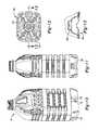
- FIGS. 1-5are views illustrating exemplary embodiments of a container with various features of the present teachings, wherein FIG. 1 is a perspective view, FIG. 2 is a side view, FIG. 3 is a front view, FIG. 4 is a bottom view, and FIG. 5 is a section view taken along the line 5 - 5 of FIG. 4 ;
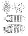
- FIGS. 6-9are views illustrating additional exemplary embodiments of a container with various features of the present teachings, wherein FIG. 6 is a perspective view, FIG. 7 is a side view, FIG. 8 is a bottom view, and FIG. 9 is a section view taken along the line 9 - 9 of FIG. 8 ;
- FIGS. 10-13are views illustrating additional exemplary embodiments of a container with various features of the present teachings, wherein FIG. 10 is a perspective view, FIG. 11 is a side view, FIG. 12 is a bottom view, and FIG. 13 is a section view taken along the line 13 - 13 of FIG. 12 ;
- FIGS. 14-17are views illustrating additional exemplary embodiments of a container with various features of the present teachings, wherein FIG. 14 is a perspective view, FIG. 15 is a side view, FIG. 16 is a bottom view, and FIG. 17 is a section view taken along the line 17 - 17 of FIG. 16 ;
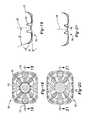
- FIGS. 18 and 19are views illustrating additional exemplary embodiments of a container with various features of the present teachings, wherein FIG. 18 is a bottom view and FIG. 19 is a section view taken along the line 19 - 19 of FIG. 18 ;
- FIGS. 20 and 21are views illustrating additional exemplary embodiments of a container with various features of the present teachings, wherein FIG. 20 is a bottom view and FIG. 21 is a section view taken along the line 21 - 21 of FIG. 20 ;
- FIGS. 22 and 23are views illustrating additional exemplary embodiments of a container with various features of the present teachings, wherein FIG. 22 is a bottom view and FIG. 23 is a section view taken along the line 23 - 23 of FIG. 22 ;
- FIGS. 24 and 25are views illustrating additional exemplary embodiments of a container with various features of the present teachings, wherein FIG. 24 is a bottom view and FIG. 25 is a section view taken along the line 25 - 25 of FIG. 24 ;
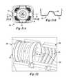
- FIGS. 26A and 26Bare section and side views, respectively, of a base portion of a container according to additional exemplary embodiments of the present disclosure
- FIGS. 27A and 27Bare section and side views, respectively, of a base portion of a container according to additional exemplary embodiments of the present disclosure
- FIGS. 28A and 28Bare front and side views, respectively, of a generally rectangular container according to additional exemplary embodiments of the present disclosure.
- FIGS. 29A and 29Bare perspective and bottom views, respectively, of a generally cylindrical container according to additional exemplary embodiments of the present disclosure.
- FIGS. 30A and 30Bare perspective and bottom views, respectively, of a generally cylindrical container according to additional exemplary embodiments of the present disclosure.
- FIGS. 31A and 31Bare views of additional exemplary embodiments of a container according to the present teachings, wherein FIG. 31 A is a bottom view and FIG. 31B is a section view taken along the line 31 B- 31 B of FIG. 31A ;
- FIG. 32is a perspective view of a mold system suitable for molding the container of the present disclosure.
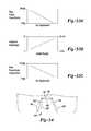
- FIGS. 33A-33Cis a series of graphs illustrating the relationship between strap inclination angle and volume displacement, the number of straps and radial strength, and the strap peak angle and volume displacement is a graph illustrating a relationship between dimensions of a strap of the container and a volume displacement of a hot-filled container;
- FIG. 34is a schematic section view of a container showing various curving surfaces of a central pushup portion thereof;
- FIGS. 35A-35Dare schematic bottom views of a central pushup portion of a container according to teachings of the present disclosure.
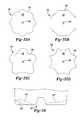
- FIG. 36is a schematic section view of a container showing various shapes for straps thereof.
- FIG. 37-39are schematic bottom views of the container showing various shapes for straps thereof.
- Example embodimentswill now be described more fully with reference to the accompanying drawings. Example embodiments are provided so that this disclosure will be thorough, and will fully convey the scope to those who are skilled in the art. Numerous specific details are set forth such as examples of specific components, devices, and methods, to provide a thorough understanding of embodiments of the present disclosure. It will be apparent to those skilled in the art that specific details need not be employed, that example embodiments may be embodied in many different forms and that neither should be construed to limit the scope of the disclosure.
- first, second, third, etc.may be used herein to describe various elements, components, regions, layers and/or sections, these elements, components, regions, layers and/or sections should not be limited by these terms. These terms may be only used to distinguish one element, component, region, layer or section from another region, layer or section. Terms such as “first,” “second,” and other numerical terms when used herein do not imply a sequence or order unless clearly indicated by the context. Thus, a first element, component, region, layer or section discussed below could be termed a second element, component, region, layer or section without departing from the teachings of the example embodiments.
- Spatially relative termssuch as “inner,” “outer,” “beneath”, “below”, “lower”, “above”, “upper” and the like, may be used herein for ease of description to describe one element or feature's relationship to another element(s) or feature(s) as illustrated in the figures. Spatially relative terms may be intended to encompass different orientations of the device in use or operation in addition to the orientation depicted in the figures. For example, if the device in the figures is turned over, elements described as “below” or “beneath” other elements or features would then be oriented “above” the other elements or features. Thus, the example term “below” can encompass both an orientation of above and below. The device may be otherwise oriented (rotated 90 degrees or at other orientations) and the spatially relative descriptors used herein interpreted accordingly.
- This disclosureprovides for a container being made of PET and incorporating a base design having an optimized size and shape that resists container loading and pressures caused by hot fill pressure and resultant vacuum, and helps maintain container shape and response.
- the size and specific configuration of the containermay not be particularly limiting and, thus, the principles of the present teachings can be applicable to a wide variety of PET container shapes. Therefore, it should be recognized that variations can exist in the present embodiments. That is, it should be appreciated that the teachings of the present disclosure can be used in a wide variety of containers, including rectangular, round, oval, squeezable, recyclable, and the like.
- the present teachingsprovide a plastic, e.g. polyethylene terephthalate (PET), container generally indicated at 10 .
- the exemplary container 10can be substantially elongated when viewed from a side and generally cylindrical when viewed from above and/or rectangular in throughout or in cross-sections (which will be discussed in greater detail herein).
- PETpolyethylene terephthalate
- the exemplary container 10can be substantially elongated when viewed from a side and generally cylindrical when viewed from above and/or rectangular in throughout or in cross-sections (which will be discussed in greater detail herein).
- Those of ordinary skill in the artwould appreciate that the following teachings of the present disclosure are applicable to other containers, such as rectangular, triangular, pentagonal, hexagonal, octagonal, polygonal, or square shaped containers, which may have different dimensions and volume capacities. It is also contemplated that other modifications can be made depending on the specific application and environmental requirements.
- container 10has been designed to retain a commodity.
- the commoditymay be in any form such as a solid or semi-solid product.
- a commoditymay be introduced into the container during a thermal process, typically a hot-fill process.
- bottlersgenerally fill the container 10 with a product at an elevated temperature between approximately 155° F. to 205° F. (approximately 68° C. to 96° C.) and seal the container 10 with a closure before cooling.
- the plastic container 10may be suitable for other high-temperature pasteurization or retort filling processes or other thermal processes as well.
- the commoditymay be introduced into the container under ambient temperatures.
- the exemplary plastic container 10defines a body 12 , and includes an upper portion 14 having a cylindrical sidewall 18 forming a finish 20 . Integrally formed with the finish 20 and extending downward therefrom is a shoulder portion 22 .
- the shoulder portion 22merges into and provides a transition between the finish 20 and a sidewall portion 24 .
- the sidewall portion 24extends downward from the shoulder portion 22 to a base portion 28 having a base 30 .
- sidewall portion 24can extend down and nearly abut base 30 , thereby minimizing the overall area of base portion 28 such that there is not a discernable base portion 28 when exemplary container 10 is uprightly-placed on a surface.
- the exemplary container 10may also have a neck 23 .
- the neck 23may have an extremely short height, that is, becoming a short extension from the finish 20 , or an elongated height, extending between the finish 20 and the shoulder portion 22 .
- the upper portion 14can define an opening for filling and dispensing of a commodity stored therein.
- the containercan be a beverage container; however, it should be appreciated that containers having different shapes, such as sidewalls and openings, can be made according to the principles of the present teachings.
- the finish 20 of the exemplary plastic container 10may include a threaded region 46 having threads 48 , a lower sealing ridge 50 , and a support ring 51 .
- the threaded regionprovides a means for attachment of a similarly threaded closure or cap (not shown).
- Alternativesmay include other suitable devices that engage the finish 20 of the exemplary plastic container 10 , such as a press-fit or snap-fit cap for example.
- the closure or capengages the finish 20 to preferably provide a hermetical seal of the exemplary plastic container 10 .
- the closure or capis preferably of a plastic or metal material conventional to the closure industry and suitable for subsequent thermal processing.
- the container 10can comprise a lightweight base configuration 100 generally formed in base portion 28 .
- Base configuration 100can comprise any one of a number of features that facilitate vacuum response, improve structural integrity, minimize container weight, and/or improve overall performance of container 10 .
- base configuration 100can be used in connection with any container shape, however, by way of illustration, containers having rectangular and cylindrical cross-sections will be examined.
- the base portion 28functions to close off the bottom portion of the plastic container 10 to retain a commodity in the container 10 .
- FIGS. 1-31Billustrate a variety of base configurations 100 and base portions 28 as well, as will be discussed.
- the base portion 28 of the plastic container 10which extends inward from the body 12 , can comprise one or more contact surfaces 134 and a central portion 136 .
- the contact surface(s) 134is the area of the base portion 28 that contacts a support surface (e.g. shelf, counter, and the like) that in turn supports the container 10 .
- the contact surface 134may be a flat surface (an individual flat surface or a collection of separately spaced flat surfaces that each lie within a common plane.
- the contact surface 134can also be a line of contact generally circumscribing, continuously or intermittently, the base portion 28 .
- the base portion 28includes four contact surfaces 134 , which are spaced away from each other about the longitudinal axis 150 of the container 10 . Also, in the embodiments shown, the contact surfaces 134 are arranged at the corners of the base portion 28 . However, it will be appreciated that there can be any number of contact surfaces 134 and the contact surfaces 134 can be disposed in any suitable position.
- the base portion 28can further include a central pushup portion 140 , which is most clearly illustrated in FIGS. 4 and 5 .
- the central pushup portion 140can be centrally located (i.e., substantially centered on the longitudinal axis 150 ).
- the central pushup portion 140can extend generally toward the finish 20 .
- the central pushup portion 140when viewed in cross section ( FIG. 5 ), is generally in the shape of a truncated cone having a top surface 146 that is generally parallel to the support surfaces 134 .
- the pushup portion 140can also include side surfaces 148 that slope upward toward the central longitudinal axis 150 of the container 10 .
- the side surfaces 148can be frusto-conic or can include a plurality of planar surfaces that are arranged in series about the axis 150 .
- the pushup portion 140can be partially frusto-conic and partially cylindrical.
- the pushup portion 140can be generally frusto-conic with a plurality of ribs 171 that extend at an angle along the side surface 148 at equal spacing about the axis 150 .
- the pushup portion 140can be annular, so that a depending frusto-conic projects exteriorly along the axis 150 .
- FIGS. 35A-35Dshow additional shapes for the pushup portion 140 (in respective bottom views of the container 10 ).
- the top surface 146can be defined by a plurality of convexly curved lines that are arranged in series about the axis ( FIG. 35A ), an octagon or other polygon ( FIG. 35B ), alternating convexly and concavely curved lines ( FIG. 35C ), and a plurality of concavely curved lines ( FIG. 35D ).
- the side surface(s) 148can project therefrom to have a corresponding shape.
- the top surface 146 and/or the side surface(s) 148can have a concave and/or convex contour.
- the top surface 146can have a concave curvature (indicated at 146 ′′) or a convex curvature (indicated at 146 ′′).
- the side surface 148can have a concave curvature (indicated at 148 ′′), a convex curvature (indicated at 148 ′′), or a S-shaped combination concave and convex curvature (indicated at 148 ′′′).
- This curvaturecan be present when the container 10 is empty.
- the curvaturecan be the result of deformation due to vacuum loads inside the container 10 .
- the side surface 148can also be stepped in some embodiments. Also, the side surface 148 can include ribs, convex or concave dimples, or rings.
- central pushup 140can vary greatly depending on various design criteria. For additional details about suitable shapes of central pushup 140 , attention should be directed to commonly-assigned U.S. patent application Ser. No. 12/847,050, which published as U.S. Patent Publication No. 2011/0017700, which was filed on Jul. 30, 2010, and which is incorporated herein by reference in its entirety.
- the central pushup 140is generally where the preform gate is captured in the mold when the container 10 is blow molded.
- Located within the top surface 146is the sub-portion of the base portion 28 , which typically includes polymer material that is not substantially molecularly oriented.
- the container 10can be hot-filled and, upon cooling, a vacuum in the container 10 can cause the central pushup 140 to move (e.g., along the axis 150 , etc.) to thereby decrease the internal volume of the container 10 .
- the central pushup 140can also resiliently bend, flex, deform, or otherwise move in response to these vacuum forces.
- the top surface 146can be flat or can convexly curve without the vacuum forces, but the vacuum forces can draw the top surface 146 upward to have a concave curvature as shown in FIG. 34 .
- the side surfaces 148can deform due to the vacuum to be concave and/or convex as shown in FIG. 34 .
- the central pushup 140can be an important component of vacuum performance of the container 10 (i.e., the ability of the container 10 to absorb these vacuum forces without losing its ability to contain the commodity, withstand top loading, etc.)
- the base portion 28can enhance such vacuum performance.
- materialcan be trapped or otherwise urged into the pushup portion of the base.
- the amount of material in these conventional applicationsis often more than is required for loading and/or vacuum response and, thus, represents unused material that adds to container weight and cost.
- Thiscan be overcome by tailoring the pushup diameter (or width in terms of non-conical applications) and/or height to achieve improved loading and/or vacuum response from thinner materials. That is, by maximizing the performance of the central pushup 140 , the remaining container portions need not be designed to withstand a greater portion of the loading and vacuum forces, thereby enabling the overall container to be made lighter at a reduced cost. When all portions of the container are made to perform more efficiently, the container can be more finely designed and manufactured.
- each container 10 having pushup 140defines several dimensions, including a pushup width Wp (which is generally a diameter of the entrance of central pushup 140 ), a pushup height Hp (which is generally a height from the contact surface 134 to the top surface 146 ), and an overall base width Wb (which is generally a diameter or width of base portion 28 of container 10 ). Based on performance testing, it has been found that relationships exist between these dimensions that lead to enhanced performance.
- central pushup 140can define a major diameter (e.g. typically equal approximately to the pushup width Wp or the diameter at the lowermost portion of central pushup 140 ).
- the central pushup 40can further define a minor diameter (e.g.
- this major diameter and minor diametercan result in the formation of a truncated conical shape.
- the surface of this truncated conical shapecan define a draft angle of less than about 45 degrees relative to central longitudinal axis 150 . It has been found that this major diameter or width can be less than about 50 mm and the minor diameter or width can be greater than about 5 mm, separately or in combination.
- the container 10can include an inversion ring 142 .
- the inversion ring 142can have a radius that is larger than the central pushup 140 , and the inversion ring 142 can completely surround and circumscribe the central pushup 140 .
- the inversion ring 142can be drawn upward along the axis 150 away from the plane defined by the contact surface 134 .
- the inversion ring 142can protrude outwardly away from the plane defined by the contact surface 134 .
- the transition between the central pushup 140 and the adjacent inversion ring 142can be rapid in order to promote as much orientation as near the central pushup 140 as possible. This serves primarily to ensure a minimal wall thickness for the inversion ring 142 , in particular at the contact surface 134 of the base portion 28 .
- the inversion ring 142may alternatively feature a small indentation, not illustrated but well known in the art, suitable for receiving a pawl that facilitates container rotation about the central longitudinal axis 150 during a labeling operation.
- the container 10can further comprise one or more straps 170 formed along and/or within base portion 28 .
- straps 170can be formed as recessed portions that are visible from the side of container 10 . That is, straps 170 can be formed such that they define a surface (i.e., a strap surface 173 that defines a strap axis of the respective strap 170 ).
- the strap surface 173can be offset at a strap distance Ds ( FIG. 2 ) from contact surface(s) 134 in the Z-axis (generally along central longitudinal axis 150 of container 10 ).
- this offset Ds between straps 170 and contact surface 134can be in the range of about 5 mm to about 25 mm.
- the strap surface 173can extend transverse to the axis 150 to terminate adjacent the sidewall portion 24 .
- the periphery of the straps 170can contour so as to transition into the sidewall portion 24 and/or the contact surfaces 134 .
- At least a portion of the strap surface 173can extend substantially parallel to the plane of the contact surfaces 134 as shown in FIGS. 1-4 . Also, in some embodiments illustrated in FIGS. 10-12 , at least a portion o the strap surface 173 can be partially inclined at a positive angle relative to the contact surface 134 . The angle can be less than 15 degrees in some embodiments. The angle can be greater than 15 degrees in other embodiments.
- FIG. 36shows various shapes that the straps 170 can have.
- the strapscan concavely contour toward the interior of the container 10 as the strap extends in the transverse direction (indicated at 170 ′′).
- the strapcan also convexly contour away from the interior as the strap extends in the transverse direction (indicated at 170 ′′).
- the strapcan have one or more steps the along the axis 150 as the strap extends in the transverse direction (indicated at 170 ′′′).
- FIGS. 37-39show how the straps can be shaped in plan view (viewed along the longitudinal axis 150 ).
- the strapcan have a sinusoidal curvature in the transverse direction (indicated at 170 ′′′′ in FIG. 37 ).
- the strapcan also include steps as the strap extends in the transverse direction (indicated at 170 in FIG. 37 ).
- the width of the strapcan increase (shown on the right side of FIG. 37 ) or can decrease (shown on the left side of FIG. 37 ) as the strap extends transversely away from the longitudinal axis 150 .
- the strapcan smoothly taper in the transverse direction (indicated at 170 in FIG. 39 ).
- the width of the strapcan either increase (top and bottom straps of FIG.
- the strapscan radiate from the longitudinal axis 150 and can each have a substantially common curvature in the transverse direction to resemble a pinwheel (indicated at 170 in FIG. 38 ). Other shapes, curvatures, etc. are also within the scope of the present disclosure.
- the shape, dimensions, and other features of the straps 170can depend upon container shape, styling, and performance criteria. Moreover, it should be recognized that the offset (along the axis 15 ) of one strap 170 can differ from the offset of another strap 170 on a single container to provide a tuned or otherwise varied load response profile. Straps 170 can interrupt contact surface 134 , thereby resulting in a plurality of contact surfaces 134 (also known as a footed or segmented standing surface). Because of the offset nature of straps 170 and their associate shape, size, and inclination (as will be discussed), straps 170 is visible from a side view orientation and formable via simplified mold systems (as will be discussed).
- straps 170can serve to reduce the overall material weight needed within base portion 28 , compared to conventional container designs, while simultaneously providing sufficient and comparable vacuum performance.
- straps 170have permitted containers according to the principles of the present teachings to achieve and/or exceed performance criteria of conventional containers while also minimizing container weight and associated costs.
- container 10can include at least one strap 170 disposed in base portion 28 .
- additional straps 170can be used, such as two, three, four, five, or more.
- Multiple straps 170can radiate from the central pushup portion 140 and the longitudinal axis 150 .
- the straps 170can be equally spaced apart about the axis 150 .
- rectangular containersmay employ two or more even-numbered straps 170 .
- the straps 170can, in some embodiments, bisect the midpoint (i.e., the middle region) of the respective sidewall. Stated differently, the strap 170 can intersect the respective sidewall approximately midway between the adjacent sidewalls. If the sidewall portion 24 defines a different polygonal cross section (taken perpendicular to the axis 150 ), the straps 170 can similarly bisect the sidewalls.
- cylindrical containersmay employ three or more odd-numbered or even-numbered straps 170 .
- straps 170can be disposed in a radial orientation such that each of the plurality of straps 170 radiates from a central point of base portion 28 to an external edge of the container 10 (e.g. adjacent sidewall portion 24 ). It should be noted, however, that although straps 170 may radiate from a central point, that does not mean that each strap 170 actually starts at the central point, but rather means that if a central axis of each strap 170 was extended inwardly they would generally meet at a common center.
- the relationship of the number of straps used to radial strength of container 10has shown an increasing radial strength with an increasing number of straps used (see FIG. 23B ).
- strap 170can be used in conjunction with the aforementioned central pushup 140 , which would thereby interrupt straps 170 .
- benefits of the present teachingsmay be realized using straps 170 without central pushup 140 .
- straps 170can define any one or a number of shapes and sizes having assorted dimensional characteristics and ranges. However, it has been found that particular strap designs can lead to improved vacuum absorption and container integrity. By way of non-limiting example, it has been found that straps 170 can define a strap plane or central axis 172 that is generally parallel to contact surface 134 and/or a surface upon which container 10 sits, thereby resulting in a low strap angle. In other embodiments, strap plane/axis 172 can be inclined relative to contact surface 135 and/or the surface upon which container 10 sits, thereby resulting in a high strap angle.
- this inclined strap plane/axis 172can be inclined such that a lowest-most portion of inclined strap plane/axis 172 is toward an inbound or central area of container 10 and a highest-most portion of inclined strap plane/axis 172 is toward an outbound or external area of container 10 (e.g. adjacent sidewall portion 24 ). Examples of such inclination can be seen in FIGS. 26B and 27B .
- Low strap anglesprovide base flexibility resulting in base flex that displaces volume through upward deflection. This upward deflection will be enhanced under vertical load providing additional volume displacement, transitioning to positive pressure to maximize filled capped topload.
- This complementary “co-flex base” technologyprovides volume displacement & filled capped topload performance thereby resulting in a “lightweight panel-less” container configuration for multi-serve applications.
- a high strap anglee.g., FIGS. 26B and 27B
- Rectangular container designsprovide sufficient volume displacement.
- This complementary “rigid-base” technologyprovides enhanced handling properties on fill-lines and tray distribution offerings thereby resulting in a “lightweight tray capable” container configuration for multi-serve applications.
- an inclination angle ⁇( FIG. 19 ) of strap plane/axis 172 of about 0 degrees to about 30 degrees (i.e. strap angle) can provide improved performance.
- This strap angle ⁇can be measured in a side cross-section take along strap plane or axis 172 relative to a horizontal reference plane or axis as shown in FIG. 19 .
- other strap anglesmay be used and/or the direction of inclination can be varied.
- the relationship of inclination angle ⁇ to volume displacement of container 10has shown an increasing volume displacement with a decreasing inclination angle ⁇ (see FIG. 33A ).
- strap 170can further define or include a secondary contour or shape when viewed generally along strap plane or axis 172 . That is, when viewing from the side of the container 10 , the strap 170 can define a peaked shape or trapezoid shape adjacent the sidewall portion 24 having a raised central area and downwardly extending side surfaces (see FIGS. 26B and 27B ) as opposed to defining a generally flat, single plane.
- the trapezoidally shaped portioncan be planar also and disposed at a draft angle relative to a horizontal (imaginary) reference line. This draft angle can be between 0 degrees and 45 degrees.
- this section of the strap 170can have a triangular shape that further provides improved vacuum response and structural integrity while simultaneously permitting reduction in material weight and costs.
- a peak 175 of the strap 170FIGS. 19, 26B and 27B
- peak angle ⁇can define a range of about 1 degree to about 45 degrees.
- peak angle ⁇can be defined a range of about 1 degree to about 45 degrees.
- other anglesmay be used and/or the direction and overall shape of strap 170 can be varied.
- the relationship of peak angle ⁇ to volume displacement of container 10has shown an increasing volume displacement with a decreasing peak angle ⁇ (see FIG. 23C ).
- base portion 28can further comprise one or more ribs 180 formed in (e.g., entirely within) or along strap 170 .
- Ribs 180can include an inwardly-directed channel (recessed toward the interior of the container 10 ) or outwardly-directed channel (projecting outward from the interior of the container 10 ).
- the rib 180can be contained entirely within the respective strap 170 or can extend out of the respective strap 170 in some embodiments.
- the ribs 180can serve to tune or otherwise modify the vacuum response characteristics of straps 170 . In this way, ribs 180 serve to modify the response profile of one or more straps 170 .
- ribs 180can follow one of a number of pathways, such as a generally V-shaped pathway ( FIGS. 29B, 30B ). In some embodiments, these pathways can define a pair of arcuate channels 182 terminating at a central radius 184 .
- the plastic container 10 of the present disclosureis a blow molded, biaxially oriented container with a unitary construction from a single or multi-layer material.
- a well-known stretch-molding, heat-setting process for making the one-piece plastic container 10generally involves the manufacture of a preform (not shown) of a polyester material, such as polyethylene terephthalate (PET), having a shape well known to those skilled in the art similar to a test-tube with a generally cylindrical cross section.
- PETpolyethylene terephthalate
- a mold system 306 for blow molding the container 10is illustrated.
- the mold system 306can be employed for the manufacture of container geometries, namely base geometries, that could not be previously made.
- the mold system 306can comprise a base system 310 disposed in operably connection with a sidewall system 320 .
- Base system 310can be configured for forming generally an entire portion of base portion 28 of container 10 and extends radially and upward until a transition to sidewall portion 24 .
- Base system 310in some embodiments, can maintain a temperature that is different from sidewall system 320 —either hotter or colder than sidewall system 320 . This can facilitate formation of container 10 to speed up or slow down the relative formation of the base portion 28 of container 10 during molding.
- base system 310can comprise a lower pressure cylinder to extend and retract a push up member 323 (shown in phantom in FIG. 32 ).
- the push up member 32can be used to extend or otherwise stretch central pushup 140 axially toward the interior of the container 10 .
- push up member 322can be centrally disposed in base system 310 .
- the push up member 322can have a retracted position, wherein the push up member 322 is close to flush with surrounding portions of the base system 310 , and an extended position (shown in phantom), wherein the push up member 322 can extend away from surrounding portions of the base system 310 .
- the push up member 322can engage the preform during forming and urge preform upward (e.g. inwardly) to form central pushup 140 . Also, following formation of central pushup 140 , push up member 322 can be retracted to permit demolding of the final container 10 from the mold. In some additional embodiments, push up member 322 of base system 310 can be paired with a counter stretch rod, if desired.
- a preform version of container 10includes a support ring, which may be used to carry or orient the preform through and at various stages of manufacture.
- the preformmay be carried by the support ring, the support ring may be used to aid in positioning the preform in a mold cavity 321 ( FIG. 32 ), or the support ring may be used to carry an intermediate container once molded.
- the preformmay be placed into the mold cavity 321 such that the support ring is captured at an upper end of the mold cavity 320 .
- the mold cavityhas an interior surface corresponding to a desired outer profile of the blown container.
- the mold cavitydefines a body forming region, an optional moil forming region and an optional opening forming region.
- an intermediate containerOnce the resultant structure (hereinafter referred to as an intermediate container) has been formed, any moil created by the moil forming region may be severed and discarded. It should be appreciated that the use of a moil forming region and/or opening forming region are not necessarily in all forming methods.
- a machineplaces the preform heated to a temperature between approximately 190° F. to 250° F. (approximately 88° C. to 121° C.) into the mold cavity.
- the mold cavitymay be heated to a temperature between approximately 250° F. to 350° F. (approximately 121° C. to 177° C.).
- a stretch rod apparatus(not illustrated) stretches or extends the heated preform within the mold cavity to a length approximately that of the intermediate container thereby molecularly orienting the polyester material in an axial direction generally corresponding with the central longitudinal axis of the container 10 .
- air having a pressure between 300 PSI to 600 PSI (2.07 MPa to 4.14 MPa)assists in extending the preform in the axial direction and in expanding the preform in a circumferential or hoop direction thereby substantially conforming the polyester material to the shape of the mold cavity and further molecularly orienting the polyester material in a direction generally perpendicular to the axial direction, thus establishing the biaxial molecular orientation of the polyester material in most of the intermediate container.
- the pressurized airholds the mostly biaxial molecularly oriented polyester material against the mold cavity for a period of approximately two (2) to five (5) seconds before removal of the intermediate container from the mold cavity. This process is known as heat setting and results in a heat-resistant container suitable for filling with a product at high temperatures.
- plastic container 10may be suitable for the manufacture of plastic container 10 .
- extrusion blow moldingsuch as for example, extrusion blow molding, one step injection stretch blow molding and injection blow molding, using other conventional materials including, for example, high density polyethylene, polypropylene, polyethylene naphthalate (PEN), a PET/PEN blend or copolymer, and various multilayer structures
- PENpolyethylene naphthalate
- PET/PEN blend or copolymera PET/PEN blend or copolymer
- multilayer structuresmay be suitable for the manufacture of plastic container 10 .
Landscapes
- Engineering & Computer Science (AREA)
- Mechanical Engineering (AREA)
- Ceramic Engineering (AREA)
- Manufacturing & Machinery (AREA)
- Containers Having Bodies Formed In One Piece (AREA)
- Packages (AREA)
- Details Of Rigid Or Semi-Rigid Containers (AREA)
- Rigid Containers With Two Or More Constituent Elements (AREA)
- Packaging Of Annular Or Rod-Shaped Articles, Wearing Apparel, Cassettes, Or The Like (AREA)
- Storage Of Web-Like Or Filamentary Materials (AREA)
- Filling Or Discharging Of Gas Storage Vessels (AREA)
- Medical Preparation Storing Or Oral Administration Devices (AREA)
- Packging For Living Organisms, Food Or Medicinal Products That Are Sensitive To Environmental Conditiond (AREA)
Abstract
Description
where ρ is the density of the PET material; ρa is the density of pure amorphous PET material (1.333 g/cc); and ρc is the density of pure crystalline material (1.455 g/cc).
Claims (22)
Priority Applications (1)
| Application Number | Priority Date | Filing Date | Title |
|---|---|---|---|
| US14/238,795US9617029B2 (en) | 2011-08-31 | 2012-08-31 | Lightweight container base |
Applications Claiming Priority (3)
| Application Number | Priority Date | Filing Date | Title |
|---|---|---|---|
| US201161529285P | 2011-08-31 | 2011-08-31 | |
| PCT/US2012/053367WO2013033550A2 (en) | 2011-08-31 | 2012-08-31 | Lightweight container base |
| US14/238,795US9617029B2 (en) | 2011-08-31 | 2012-08-31 | Lightweight container base |
Related Parent Applications (1)
| Application Number | Title | Priority Date | Filing Date |
|---|---|---|---|
| PCT/US2012/053367A-371-Of-InternationalWO2013033550A2 (en) | 2011-08-31 | 2012-08-31 | Lightweight container base |
Related Child Applications (1)
| Application Number | Title | Priority Date | Filing Date |
|---|---|---|---|
| US15/440,002DivisionUS10392151B2 (en) | 2011-08-31 | 2017-02-23 | Lightweight container base |
Publications (2)
| Publication Number | Publication Date |
|---|---|
| US20140197127A1 US20140197127A1 (en) | 2014-07-17 |
| US9617029B2true US9617029B2 (en) | 2017-04-11 |
Family
ID=47757183
Family Applications (4)
| Application Number | Title | Priority Date | Filing Date |
|---|---|---|---|
| US14/238,795Active2032-09-21US9617029B2 (en) | 2011-08-31 | 2012-08-31 | Lightweight container base |
| US14/424,569Active2032-10-04US9422076B2 (en) | 2011-08-31 | 2013-08-30 | Lightweight container base |
| US14/465,494Active2032-09-06US9694930B2 (en) | 2011-08-31 | 2014-08-21 | Lightweight container base |
| US15/440,002Active2033-02-21US10392151B2 (en) | 2011-08-31 | 2017-02-23 | Lightweight container base |
Family Applications After (3)
| Application Number | Title | Priority Date | Filing Date |
|---|---|---|---|
| US14/424,569Active2032-10-04US9422076B2 (en) | 2011-08-31 | 2013-08-30 | Lightweight container base |
| US14/465,494Active2032-09-06US9694930B2 (en) | 2011-08-31 | 2014-08-21 | Lightweight container base |
| US15/440,002Active2033-02-21US10392151B2 (en) | 2011-08-31 | 2017-02-23 | Lightweight container base |
Country Status (7)
| Country | Link |
|---|---|
| US (4) | US9617029B2 (en) |
| BR (2) | BR112015004526B1 (en) |
| CO (2) | CO6890084A2 (en) |
| ES (1) | ES2784786T3 (en) |
| MX (2) | MX353418B (en) |
| PE (3) | PE20141925A1 (en) |
| WO (1) | WO2013033550A2 (en) |
Cited By (6)
| Publication number | Priority date | Publication date | Assignee | Title |
|---|---|---|---|---|
| US20150259090A1 (en)* | 2012-11-30 | 2015-09-17 | Alpla Werke Alwin Lehner Gmbh & Co. Kg | Plastic container |
| US10221001B2 (en)* | 2014-07-30 | 2019-03-05 | S.I.P.A. Societa' Industrializzazione Progettazione E Automazione S.P.A. | Container with pressure variation compensation |
| USD1011889S1 (en) | 2021-06-07 | 2024-01-23 | Altium Packaging Lp | Container |
| US11952163B2 (en) | 2021-06-07 | 2024-04-09 | Altium Packaging Lp | Container with reinforced neck |
| US11975460B2 (en) | 2019-03-04 | 2024-05-07 | Amcor Rigid Packaging Usa, Llc | Preform design for lightweight container |
| USD1085883S1 (en)* | 2023-09-28 | 2025-07-29 | Plastipak Packaging, Inc. | Container base |
Families Citing this family (40)
| Publication number | Priority date | Publication date | Assignee | Title |
|---|---|---|---|---|
| US9272827B2 (en) | 2008-08-29 | 2016-03-01 | Pepsico, Inc. | Post-mix beverage system |
| US10538357B2 (en) | 2011-08-31 | 2020-01-21 | Amcor Rigid Plastics Usa, Llc | Lightweight container base |
| US10532848B2 (en) | 2011-08-31 | 2020-01-14 | Amcor Rigid Plastics Usa, Llc | Lightweight container base |
| MX353418B (en) | 2011-08-31 | 2018-01-11 | Amcor Group Gmbh | Lightweight container base. |
| US11845581B2 (en)* | 2011-12-05 | 2023-12-19 | Niagara Bottling, Llc | Swirl bell bottle with wavy ribs |
| US9120589B2 (en)* | 2012-12-27 | 2015-09-01 | Niagara Bottling, Llc | Plastic container with strapped base |
| EP3536623B1 (en) | 2011-12-05 | 2024-04-17 | Niagara Bottling, LLC | Plastic container with varying depth ribs |
| DE102012003219B4 (en) | 2012-02-20 | 2025-06-26 | Krones Ag | plastic container |
| US10543121B2 (en) | 2014-03-31 | 2020-01-28 | Amcor Rigid Plastics Usa, Llc | Controlled release container |
| EP3145822B1 (en)* | 2014-05-23 | 2022-02-09 | Plastipak BAWT S.à.r.l. | Heat resistant and biaxially stretched blow-molded plastic container having a base movable to accommodate internal vacuum forces and issued from a double-blow process |
| USD756233S1 (en)* | 2014-08-13 | 2016-05-17 | Quimica Goncal S.A. De C.V. | Twist top pet bottle for softener |
| EP3183178B1 (en)* | 2014-08-21 | 2020-02-26 | Amcor Rigid Plastics USA, LLC | Lightweight container base |
| KR102662489B1 (en) | 2015-03-31 | 2024-05-02 | 피셔 앤 페이켈 핼스케어 리미티드 | User interface and system for gassing the airway |
| USD784142S1 (en)* | 2015-04-07 | 2017-04-18 | Societe Des Eaux De Volvic | Bottle |
| US10934049B2 (en)* | 2015-10-09 | 2021-03-02 | Fresenius Kabi Deutschland Gmbh | Container for receiving an enteral nutrition solution |
| BR112018011484B1 (en) | 2015-12-07 | 2022-05-10 | Amcor Group Gmbh | Top load force application method |
| USD797563S1 (en)* | 2016-01-12 | 2017-09-19 | Quimica Goncal S.A. De C.V. | Cleaner bottle |
| US10464797B2 (en) | 2016-01-15 | 2019-11-05 | Pepsico, Inc. | Post-mix beverage system |
| US10610045B2 (en) | 2016-06-14 | 2020-04-07 | Pepsico, Inc. | Beverage system including a removable piercer |
| EP3995168B8 (en) | 2016-08-11 | 2025-09-03 | Fisher & Paykel Healthcare Limited | A collapsible conduit, patient interface and headgear connector |
| CA3041890A1 (en)* | 2016-11-14 | 2018-05-17 | Amcor Rigid Plastics Usa, Llc | Lightweight container base |
| PE20200067A1 (en)* | 2017-04-28 | 2020-01-15 | Amcor Rigid Plastics Usa Llc | LIGHTWEIGHT CONTAINER BASE |
| MX2020011255A (en)* | 2018-04-26 | 2020-11-12 | Graham Packaging Co | Pressurized refill container resistant to standing ring cracking. |
| US11718439B2 (en)* | 2018-05-11 | 2023-08-08 | Amcor Rigid Packaging Usa, Llc | Container pressure base |
| US10926911B2 (en) | 2018-10-15 | 2021-02-23 | Pepsico. Inc. | Plastic bottle with base |
| US11027884B2 (en)* | 2019-01-18 | 2021-06-08 | Altium Packaging Lp | Container and method of manufacturing the same |
| USD920799S1 (en) | 2019-01-18 | 2021-06-01 | Altium Packaging Lp | Container |
| DE102019105005A1 (en)* | 2019-02-27 | 2020-08-27 | Krones Ag | Plastic container with groove geometry |
| USD927982S1 (en) | 2019-07-18 | 2021-08-17 | Altium Packaging Lp | Container |
| WO2021081227A1 (en)* | 2019-10-25 | 2021-04-29 | Niagara Bottling, Llc | Bottle assembly |
| EP3842024B1 (en)* | 2019-12-20 | 2025-02-05 | SCHOTT Pharma AG & Co. KGaA | Glass container comprising a glass bottom with improved properties |
| JP7370248B2 (en)* | 2019-12-27 | 2023-10-27 | 株式会社吉野工業所 | Bottle |
| US11858680B2 (en) | 2020-01-14 | 2024-01-02 | Altium Packaging Lp | Container and method of manufacturing the same |
| USD937679S1 (en) | 2020-03-11 | 2021-12-07 | Niagara Bottling, Llc | Bottle |
| US12139296B2 (en)* | 2020-03-27 | 2024-11-12 | Amcor Rigid Packaging Usa, Llc | Multi-serve container with oval cross-section |
| AU2021202920A1 (en)* | 2020-05-08 | 2021-11-25 | Orora Packaging Australia Pty Ltd | A bottle, and an insert and a mould for making the bottle |
| USD968229S1 (en) | 2021-01-08 | 2022-11-01 | Altium Packaging Lp | Container |
| USD1066988S1 (en) | 2021-04-07 | 2025-03-18 | Niagara Bottling, Llc | Bottle |
| DE102021125276A1 (en) | 2021-09-29 | 2023-03-30 | Krones Aktiengesellschaft | Plastic container with a stable bottom design |
| US12129072B2 (en)* | 2021-11-30 | 2024-10-29 | Pepsico, Inc. | Flexible base for aseptic-fill bottles |
Citations (60)
| Publication number | Priority date | Publication date | Assignee | Title |
|---|---|---|---|---|
| US2641374A (en)* | 1949-10-29 | 1953-06-09 | Yee Sing Chun | Container |
| US3598270A (en)* | 1969-04-14 | 1971-08-10 | Continental Can Co | Bottom end structure for plastic containers |
| US3727783A (en)* | 1971-06-15 | 1973-04-17 | Du Pont | Noneverting bottom for thermoplastic bottles |
| US4134510A (en)* | 1975-06-16 | 1979-01-16 | Owens-Illinois, Inc. | Bottle having ribbed bottom |
| US4231483A (en)* | 1977-11-10 | 1980-11-04 | Solvay & Cie. | Hollow article made of an oriented thermoplastic |
| US4249666A (en)* | 1977-03-02 | 1981-02-10 | Solvay & Cie | Hollow body of thermoplastic material |
| US4372455A (en)* | 1980-01-18 | 1983-02-08 | National Can Corporation | Thin walled plastic container construction |
| US4892205A (en) | 1988-07-15 | 1990-01-09 | Hoover Universal, Inc. | Concentric ribbed preform and bottle made from same |
| US4978015A (en) | 1990-01-10 | 1990-12-18 | North American Container, Inc. | Plastic container for pressurized fluids |
| US4993566A (en)* | 1989-12-19 | 1991-02-19 | Hoover Universal, Inc. | Spiral container base structure for hot fill pet container |
| US5024340A (en)* | 1990-07-23 | 1991-06-18 | Sewell Plastics, Inc. | Wide stance footed bottle |
| US5024339A (en)* | 1989-02-27 | 1991-06-18 | Mendle Limited | Plastics bottle |
| US5080244A (en)* | 1978-11-07 | 1992-01-14 | Yoshino Kogyosho Co., Ltd. | Synthetic resin thin-walled bottle and method of producing same |
| US5133468A (en)* | 1991-06-14 | 1992-07-28 | Constar Plastics Inc. | Footed hot-fill container |
| USD332747S (en)* | 1991-09-11 | 1993-01-26 | Plastipak Packaging, Inc. | Bottle with handle |
| JPH0577834A (en) | 1991-09-10 | 1993-03-30 | Dainippon Printing Co Ltd | Pressure resistant self-supporting container and manufacturing method thereof |
| US5427258A (en)* | 1992-04-09 | 1995-06-27 | Continental Pet Technologies, Inc. | Freestanding container with improved combination of properties |
| US5507402A (en) | 1993-05-05 | 1996-04-16 | Aci Operations Pty. Ltd. | Plastic bottle with a self supporting base structure |
| US5549210A (en)* | 1993-12-13 | 1996-08-27 | Brunswick Container Corporation | Wide stance footed bottle with radially non-uniform circumference footprint |
| US5756018A (en)* | 1995-03-22 | 1998-05-26 | Pepsico, Inc. | Footed plastic bottle |
| USD418423S (en)* | 1998-10-19 | 2000-01-04 | Danone International Brands, Inc. | Jug |
| US6019236A (en) | 1997-09-10 | 2000-02-01 | Plastipak Packaging, Inc. | Plastic blow molded container having stable freestanding base |
| JP2000079927A (en) | 1998-09-01 | 2000-03-21 | Toppan Printing Co Ltd | Heat and pressure resistant blow molded bottles |
| US6112925A (en)* | 1997-02-21 | 2000-09-05 | Continental Pet Technologies, Inc. | Enhanced shelf-life pressurized container with ribbed appearance |
| US20020074336A1 (en)* | 2000-07-24 | 2002-06-20 | Silvers Kerry W. | Container base structure |
| US20020153343A1 (en)* | 2001-04-19 | 2002-10-24 | Tobias John W. | Multi-functional base for a plastic, wide-mouth, blow-molded container |
| US6527133B1 (en)* | 2000-11-03 | 2003-03-04 | Portola Packaging, Inc. | Multiple label liquid container |
| US20030052076A1 (en)* | 2001-09-17 | 2003-03-20 | Cheng J. John | Base for plastic container |
| US20030132190A1 (en)* | 1995-11-01 | 2003-07-17 | Zhang Peter Q. | Blow molded plastic container and method of making |
| US20030155324A1 (en)* | 2000-11-03 | 2003-08-21 | Mccollum Matthew S. | Multiple label container |
| US20030196926A1 (en) | 2001-04-19 | 2003-10-23 | Tobias John W. | Multi-functional base for a plastic, wide-mouth, blow-molded container |
| US20040094502A1 (en)* | 2001-04-03 | 2004-05-20 | Michel Boukobza | Thermoplastic container whereof the base comprises a cross-shaped impression |
| US7017763B2 (en)* | 2002-07-24 | 2006-03-28 | Graham Packaging Company, L.P. | Base having a flexible vacuum area |
| US7287658B1 (en)* | 2004-01-08 | 2007-10-30 | Berry Plastics Corporation | Container having a base with a convex dome and method of use |
| US20070262046A1 (en)* | 2004-12-24 | 2007-11-15 | Enrico Zoppas | Plastic Bottle Base |
| US20080073315A1 (en)* | 2006-09-22 | 2008-03-27 | Sidel Participations | Container with an at least partially triangular prismatic body |
| US20080173614A1 (en)* | 2007-01-18 | 2008-07-24 | The Coca-Cola Company | Beverage container having a modified shape |
| US7451886B2 (en)* | 2003-05-23 | 2008-11-18 | Amcor Limited | Container base structure responsive to vacuum related forces |
| US20090159556A1 (en) | 2003-05-23 | 2009-06-25 | Amcor Limited | Container base structure responsive to vacuum related forces |
| USD604623S1 (en)* | 2009-01-13 | 2009-11-24 | Hp Hood Llc | Liquid container |
| US20100072165A1 (en)* | 2008-09-15 | 2010-03-25 | Alexander Schau | Plastic container |
| US20100163515A1 (en)* | 2007-08-31 | 2010-07-01 | Toyo Seikan Kaisha | Synthetic resin container |
| US20100326950A1 (en) | 2009-06-29 | 2010-12-30 | Lane Michael T | Container having oriented standing surface |
| US20110017700A1 (en) | 2003-05-23 | 2011-01-27 | Patcheak Terry D | Hot-fill container |
| US20110049083A1 (en) | 2009-09-01 | 2011-03-03 | Scott Anthony J | Base for pressurized bottles |
| US20110309090A1 (en)* | 2006-08-08 | 2011-12-22 | Sidel Participations | Bottom of a hollow body obtained by blowing or stretch-blowing a preform of a thermoplastic material, and hollow body comprising such a bottom |
| US20120241405A1 (en)* | 2011-03-23 | 2012-09-27 | Peter Lobbestael | Method and apparatus for making a light weight container |
| US20130043255A1 (en)* | 2010-04-21 | 2013-02-21 | Sidel Participations | Strengthened petaloid base of a container |
| US20130213925A1 (en)* | 2012-02-20 | 2013-08-22 | Krones Ag | Plastic container |
| US8739994B1 (en)* | 2013-03-12 | 2014-06-03 | Graham Packaging Company, L.P. | Container and base with deflectable dome |
| US20140183202A1 (en)* | 2012-12-27 | 2014-07-03 | Niagara Bottling, Llc | Plastic container with strapped base |
| US20150034660A1 (en)* | 2012-05-04 | 2015-02-05 | Pet Engineering S.R.L. | Bottle made of polymer material |
| US20150144587A1 (en)* | 2012-12-27 | 2015-05-28 | Niagara Bottling, Llc | Swirl Bell Bottle With Wavy Ribs |
| US20150298848A1 (en)* | 2012-11-30 | 2015-10-22 | Sidel Participations | Container having a bottom provided with a vault with a double indentation |
| US20150314907A1 (en)* | 2012-12-03 | 2015-11-05 | Suntory Beverage & Food Limited | Resin container |
| US20150329234A1 (en)* | 2012-12-27 | 2015-11-19 | Niagara Bottling, Llc | Plastic Container With Strapped Base |
| US20160137331A1 (en)* | 2014-11-13 | 2016-05-19 | Niagara Bottling, Llc | Carbonated soft drink finish modification |
| US20160144992A1 (en)* | 2013-06-25 | 2016-05-26 | Sidel Participations | Container having a petaloid base and groove |
| US20160167825A1 (en)* | 2013-04-15 | 2016-06-16 | Krones Ag | Plastic container and blow mould for the production thereof |
| US20160272356A1 (en)* | 2015-03-16 | 2016-09-22 | Mid-America Machining, Inc. | Lightweight dairy container |
Family Cites Families (21)
| Publication number | Priority date | Publication date | Assignee | Title |
|---|---|---|---|---|
| US278205A (en)* | 1883-05-22 | weiss | ||
| US97922A (en)* | 1869-12-14 | hougrhton | ||
| US4054219A (en)* | 1976-05-26 | 1977-10-18 | Beatrice Foods | Drainable container base |
| JPS6213669A (en) | 1985-07-12 | 1987-01-22 | 五反田 基博 | Lock apparatus of locker also used as delivered product receiver |
| JP2996451B2 (en) | 1991-09-06 | 1999-12-27 | 大日本印刷株式会社 | Manufacturing method of pressure-resistant self-standing container |
| DE69313862T3 (en)* | 1992-07-07 | 2001-04-26 | Continental Pet Technologies, Inc. | METHOD FOR MOLDING A CONTAINER WITH A SIDEWALL OF HIGH CRYSTALITY AND A BOTTOM OF LOW CRYSTALITY |
| US6223920B1 (en)* | 1998-05-19 | 2001-05-01 | Sclimalbach-Lubeca, Ag | Hot-fillable blow molded container with pinch-grip vacuum panels |
| US20040173565A1 (en)* | 1999-12-01 | 2004-09-09 | Frank Semersky | Pasteurizable wide-mouth container |
| US7543713B2 (en)* | 2001-04-19 | 2009-06-09 | Graham Packaging Company L.P. | Multi-functional base for a plastic, wide-mouth, blow-molded container |
| JP3918613B2 (en)* | 2002-04-05 | 2007-05-23 | 東洋製罐株式会社 | Heat resistant polyester container and method for producing the same |
| US6857531B2 (en)* | 2003-01-30 | 2005-02-22 | Plastipak Packaging, Inc. | Plastic container |
| US7377399B2 (en)* | 2003-02-10 | 2008-05-27 | Amcor Limited | Inverting vacuum panels for a plastic container |
| FR2904809B1 (en)* | 2006-08-08 | 2008-10-24 | Sidel Participations | HOLLOW BODY BASE OBTAINED BY BLOWING OR STRETCH BLOWING A PREFORM IN THERMOPLASTIC MATERIAL, HOLLOW BODY COMPRISING SUCH A BOTTOM |
| JP5024168B2 (en)* | 2008-03-25 | 2012-09-12 | 東洋製罐株式会社 | Plastic container |
| FR2932458B1 (en)* | 2008-06-13 | 2010-08-20 | Sidel Participations | CONTAINER, IN PARTICULAR BOTTLE, IN THERMOPLASTIC MATERIAL EQUIPPED WITH A REINFORCED BACKGROUND |
| DE102009011583A1 (en)* | 2009-03-06 | 2010-09-09 | Krones Ag | Method and device for producing and filling thin-walled beverage containers |
| US8567624B2 (en)* | 2009-06-30 | 2013-10-29 | Ocean Spray Cranberries, Inc. | Lightweight, high strength bottle |
| JP5077834B2 (en) | 2009-12-15 | 2012-11-21 | 日本精工株式会社 | Toroidal continuously variable transmission |
| JP5584929B2 (en) | 2010-12-17 | 2014-09-10 | サントリーホールディングス株式会社 | Resin container |
| MX353418B (en) | 2011-08-31 | 2018-01-11 | Amcor Group Gmbh | Lightweight container base. |
| USD704062S1 (en)* | 2012-02-14 | 2014-05-06 | Amcor Limited | Container |
- 2012
- 2012-08-31MXMX2014002184Apatent/MX353418B/enactiveIP Right Grant
- 2012-08-31WOPCT/US2012/053367patent/WO2013033550A2/enactiveApplication Filing
- 2012-08-31USUS14/238,795patent/US9617029B2/enactiveActive
- 2012-08-31PEPE2014000288Apatent/PE20141925A1/enactiveIP Right Grant
- 2013
- 2013-08-30BRBR112015004526-0Apatent/BR112015004526B1/enactiveIP Right Grant
- 2013-08-30PEPE2015000258Apatent/PE20150505A1/enactiveIP Right Grant
- 2013-08-30USUS14/424,569patent/US9422076B2/enactiveActive
- 2014
- 2014-02-27COCO14042091Apatent/CO6890084A2/enunknown
- 2014-08-21USUS14/465,494patent/US9694930B2/enactiveActive
- 2015
- 2015-06-29ESES15833585Tpatent/ES2784786T3/enactiveActive
- 2015-06-29PEPE2017000242Apatent/PE20170731A1/enunknown
- 2015-06-29BRBR112017003563-4Apatent/BR112017003563B1/enactiveIP Right Grant
- 2015-06-29MXMX2017002059Apatent/MX382892B/enunknown
- 2017
- 2017-02-23USUS15/440,002patent/US10392151B2/enactiveActive
- 2017-02-24COCONC2017/0001749Apatent/CO2017001749A2/enunknown
Patent Citations (62)
| Publication number | Priority date | Publication date | Assignee | Title |
|---|---|---|---|---|
| US2641374A (en)* | 1949-10-29 | 1953-06-09 | Yee Sing Chun | Container |
| US3598270A (en)* | 1969-04-14 | 1971-08-10 | Continental Can Co | Bottom end structure for plastic containers |
| US3727783A (en)* | 1971-06-15 | 1973-04-17 | Du Pont | Noneverting bottom for thermoplastic bottles |
| US4134510A (en)* | 1975-06-16 | 1979-01-16 | Owens-Illinois, Inc. | Bottle having ribbed bottom |
| US4249666A (en)* | 1977-03-02 | 1981-02-10 | Solvay & Cie | Hollow body of thermoplastic material |
| US4231483A (en)* | 1977-11-10 | 1980-11-04 | Solvay & Cie. | Hollow article made of an oriented thermoplastic |
| US5080244A (en)* | 1978-11-07 | 1992-01-14 | Yoshino Kogyosho Co., Ltd. | Synthetic resin thin-walled bottle and method of producing same |
| US4372455A (en)* | 1980-01-18 | 1983-02-08 | National Can Corporation | Thin walled plastic container construction |
| US4892205A (en) | 1988-07-15 | 1990-01-09 | Hoover Universal, Inc. | Concentric ribbed preform and bottle made from same |
| US5024339A (en)* | 1989-02-27 | 1991-06-18 | Mendle Limited | Plastics bottle |
| US4993566A (en)* | 1989-12-19 | 1991-02-19 | Hoover Universal, Inc. | Spiral container base structure for hot fill pet container |
| US4978015A (en) | 1990-01-10 | 1990-12-18 | North American Container, Inc. | Plastic container for pressurized fluids |
| US5024340A (en)* | 1990-07-23 | 1991-06-18 | Sewell Plastics, Inc. | Wide stance footed bottle |
| US5133468A (en)* | 1991-06-14 | 1992-07-28 | Constar Plastics Inc. | Footed hot-fill container |
| JPH0577834A (en) | 1991-09-10 | 1993-03-30 | Dainippon Printing Co Ltd | Pressure resistant self-supporting container and manufacturing method thereof |
| USD332747S (en)* | 1991-09-11 | 1993-01-26 | Plastipak Packaging, Inc. | Bottle with handle |
| US5427258A (en)* | 1992-04-09 | 1995-06-27 | Continental Pet Technologies, Inc. | Freestanding container with improved combination of properties |
| US5507402A (en) | 1993-05-05 | 1996-04-16 | Aci Operations Pty. Ltd. | Plastic bottle with a self supporting base structure |
| US5549210A (en)* | 1993-12-13 | 1996-08-27 | Brunswick Container Corporation | Wide stance footed bottle with radially non-uniform circumference footprint |
| US5756018A (en)* | 1995-03-22 | 1998-05-26 | Pepsico, Inc. | Footed plastic bottle |
| US20030132190A1 (en)* | 1995-11-01 | 2003-07-17 | Zhang Peter Q. | Blow molded plastic container and method of making |
| US6112925A (en)* | 1997-02-21 | 2000-09-05 | Continental Pet Technologies, Inc. | Enhanced shelf-life pressurized container with ribbed appearance |
| US6019236A (en) | 1997-09-10 | 2000-02-01 | Plastipak Packaging, Inc. | Plastic blow molded container having stable freestanding base |
| JP2000079927A (en) | 1998-09-01 | 2000-03-21 | Toppan Printing Co Ltd | Heat and pressure resistant blow molded bottles |
| USD418423S (en)* | 1998-10-19 | 2000-01-04 | Danone International Brands, Inc. | Jug |
| US20020074336A1 (en)* | 2000-07-24 | 2002-06-20 | Silvers Kerry W. | Container base structure |
| US6527133B1 (en)* | 2000-11-03 | 2003-03-04 | Portola Packaging, Inc. | Multiple label liquid container |
| US20030155324A1 (en)* | 2000-11-03 | 2003-08-21 | Mccollum Matthew S. | Multiple label container |
| US20040094502A1 (en)* | 2001-04-03 | 2004-05-20 | Michel Boukobza | Thermoplastic container whereof the base comprises a cross-shaped impression |
| US20030196926A1 (en) | 2001-04-19 | 2003-10-23 | Tobias John W. | Multi-functional base for a plastic, wide-mouth, blow-molded container |
| US20020153343A1 (en)* | 2001-04-19 | 2002-10-24 | Tobias John W. | Multi-functional base for a plastic, wide-mouth, blow-molded container |
| US20030052076A1 (en)* | 2001-09-17 | 2003-03-20 | Cheng J. John | Base for plastic container |
| US7017763B2 (en)* | 2002-07-24 | 2006-03-28 | Graham Packaging Company, L.P. | Base having a flexible vacuum area |
| US7451886B2 (en)* | 2003-05-23 | 2008-11-18 | Amcor Limited | Container base structure responsive to vacuum related forces |
| US20110017700A1 (en) | 2003-05-23 | 2011-01-27 | Patcheak Terry D | Hot-fill container |
| US20090159556A1 (en) | 2003-05-23 | 2009-06-25 | Amcor Limited | Container base structure responsive to vacuum related forces |
| US7287658B1 (en)* | 2004-01-08 | 2007-10-30 | Berry Plastics Corporation | Container having a base with a convex dome and method of use |
| US7789255B2 (en)* | 2004-12-24 | 2010-09-07 | Acqua Minerale S. Benedetto - S.P.A. | Plastic bottle base |
| US20070262046A1 (en)* | 2004-12-24 | 2007-11-15 | Enrico Zoppas | Plastic Bottle Base |
| US20110309090A1 (en)* | 2006-08-08 | 2011-12-22 | Sidel Participations | Bottom of a hollow body obtained by blowing or stretch-blowing a preform of a thermoplastic material, and hollow body comprising such a bottom |
| US20080073315A1 (en)* | 2006-09-22 | 2008-03-27 | Sidel Participations | Container with an at least partially triangular prismatic body |
| US20080173614A1 (en)* | 2007-01-18 | 2008-07-24 | The Coca-Cola Company | Beverage container having a modified shape |
| US20100163515A1 (en)* | 2007-08-31 | 2010-07-01 | Toyo Seikan Kaisha | Synthetic resin container |
| US20100072165A1 (en)* | 2008-09-15 | 2010-03-25 | Alexander Schau | Plastic container |
| USD604623S1 (en)* | 2009-01-13 | 2009-11-24 | Hp Hood Llc | Liquid container |
| US20100326950A1 (en) | 2009-06-29 | 2010-12-30 | Lane Michael T | Container having oriented standing surface |
| US20110049083A1 (en) | 2009-09-01 | 2011-03-03 | Scott Anthony J | Base for pressurized bottles |
| US20130043255A1 (en)* | 2010-04-21 | 2013-02-21 | Sidel Participations | Strengthened petaloid base of a container |
| US20120241405A1 (en)* | 2011-03-23 | 2012-09-27 | Peter Lobbestael | Method and apparatus for making a light weight container |
| US20130213925A1 (en)* | 2012-02-20 | 2013-08-22 | Krones Ag | Plastic container |
| US20140238951A1 (en)* | 2012-02-20 | 2014-08-28 | Krones Ag | Plastic container |
| US20150034660A1 (en)* | 2012-05-04 | 2015-02-05 | Pet Engineering S.R.L. | Bottle made of polymer material |
| US20150298848A1 (en)* | 2012-11-30 | 2015-10-22 | Sidel Participations | Container having a bottom provided with a vault with a double indentation |
| US20150314907A1 (en)* | 2012-12-03 | 2015-11-05 | Suntory Beverage & Food Limited | Resin container |
| US20150144587A1 (en)* | 2012-12-27 | 2015-05-28 | Niagara Bottling, Llc | Swirl Bell Bottle With Wavy Ribs |
| US20140183202A1 (en)* | 2012-12-27 | 2014-07-03 | Niagara Bottling, Llc | Plastic container with strapped base |
| US20150329234A1 (en)* | 2012-12-27 | 2015-11-19 | Niagara Bottling, Llc | Plastic Container With Strapped Base |
| US8739994B1 (en)* | 2013-03-12 | 2014-06-03 | Graham Packaging Company, L.P. | Container and base with deflectable dome |
| US20160167825A1 (en)* | 2013-04-15 | 2016-06-16 | Krones Ag | Plastic container and blow mould for the production thereof |
| US20160144992A1 (en)* | 2013-06-25 | 2016-05-26 | Sidel Participations | Container having a petaloid base and groove |
| US20160137331A1 (en)* | 2014-11-13 | 2016-05-19 | Niagara Bottling, Llc | Carbonated soft drink finish modification |
| US20160272356A1 (en)* | 2015-03-16 | 2016-09-22 | Mid-America Machining, Inc. | Lightweight dairy container |
Non-Patent Citations (4)
| Title |
|---|
| International Search Report and Written Opinion dated Dec. 2, 2013 in corresponding international patent application Serial No. PCT/US2013/057708 (sixteen pages). |
| International Search Report and Written Opinion for PCT/US2012/053367, mailed Feb. 14, 2013; ISA/KR. |
| U.S. Appl. No. 14/424,569, filed Feb. 27, 2015, Lane et al. |
| U.S. Appl. No. 14/465,494, filed Aug. 21, 2014, Lane et al. |
Cited By (7)
| Publication number | Priority date | Publication date | Assignee | Title |
|---|---|---|---|---|
| US20150259090A1 (en)* | 2012-11-30 | 2015-09-17 | Alpla Werke Alwin Lehner Gmbh & Co. Kg | Plastic container |
| US9957077B2 (en)* | 2012-11-30 | 2018-05-01 | Alpla Werke Alwin Lehner Gmbh & Co. Kg | Plastic container |
| US10221001B2 (en)* | 2014-07-30 | 2019-03-05 | S.I.P.A. Societa' Industrializzazione Progettazione E Automazione S.P.A. | Container with pressure variation compensation |
| US11975460B2 (en) | 2019-03-04 | 2024-05-07 | Amcor Rigid Packaging Usa, Llc | Preform design for lightweight container |
| USD1011889S1 (en) | 2021-06-07 | 2024-01-23 | Altium Packaging Lp | Container |
| US11952163B2 (en) | 2021-06-07 | 2024-04-09 | Altium Packaging Lp | Container with reinforced neck |
| USD1085883S1 (en)* | 2023-09-28 | 2025-07-29 | Plastipak Packaging, Inc. | Container base |
Also Published As
| Publication number | Publication date |
|---|---|
| WO2013033550A3 (en) | 2013-06-13 |
| MX382892B (en) | 2025-03-13 |
| BR112017003563A2 (en) | 2017-12-05 |
| MX2014002184A (en) | 2014-05-30 |
| US10392151B2 (en) | 2019-08-27 |
| BR112014005038A2 (en) | 2017-03-21 |
| US20140197127A1 (en) | 2014-07-17 |
| US20170158371A1 (en) | 2017-06-08 |
| US20140360972A1 (en) | 2014-12-11 |
| MX2017002059A (en) | 2017-08-14 |
| MX353418B (en) | 2018-01-11 |
| ES2784786T3 (en) | 2020-09-30 |
| WO2013033550A2 (en) | 2013-03-07 |
| BR112015004526B1 (en) | 2021-05-18 |
| BR112017003563B1 (en) | 2021-09-08 |
| US20150225109A1 (en) | 2015-08-13 |
| PE20170731A1 (en) | 2017-07-04 |
| CO6890084A2 (en) | 2014-03-10 |
| PE20150505A1 (en) | 2015-04-29 |
| US9694930B2 (en) | 2017-07-04 |
| US9422076B2 (en) | 2016-08-23 |
| BR112015004526A2 (en) | 2017-07-04 |
| PE20141925A1 (en) | 2014-12-05 |
| CO2017001749A2 (en) | 2017-05-10 |
Similar Documents
| Publication | Publication Date | Title |
|---|---|---|
| US10392151B2 (en) | Lightweight container base | |
| US9833938B2 (en) | Heat-set container and mold system thereof | |
| US8813996B2 (en) | Heat set container | |
| US10532848B2 (en) | Lightweight container base | |
| US8561821B2 (en) | Heat set container | |
| US8556097B2 (en) | Container having vacuum panel with balanced vacuum and pressure response | |
| US8505757B2 (en) | Shoulder rib to direct top load force | |
| US8528760B2 (en) | Lightweight container having mid-body grip | |
| US10022894B2 (en) | Preform design for lightweight container | |
| EP3538444B1 (en) | Method of providing a filled container | |
| US10723504B2 (en) | Heat set container with label boundary panel | |
| WO2014036516A1 (en) | Lightweight container base | |
| US11091289B2 (en) | Lightweight container base | |
| EP3183178B1 (en) | Lightweight container base | |
| EP3615436A1 (en) | Lightweight container base | |
| BR112014005038B1 (en) | LIGHTWEIGHT CONTAINER BASE |
Legal Events
| Date | Code | Title | Description |
|---|---|---|---|
| AS | Assignment | Owner name:AMCOR LIMITED, AUSTRALIA Free format text:ASSIGNMENT OF ASSIGNORS INTEREST;ASSIGNORS:LANE, MICHAEL T.;PAEGEL, WALT;REEL/FRAME:028975/0975 Effective date:20120917 | |
| AS | Assignment | Owner name:AMCOR LIMITED, AUSTRALIA Free format text:ASSIGNMENT OF ASSIGNORS INTEREST;ASSIGNORS:LANE, MICHAEL T.;PAEGEL, WALT;REEL/FRAME:034839/0535 Effective date:20141218 | |
| STCF | Information on status: patent grant | Free format text:PATENTED CASE | |
| AS | Assignment | Owner name:AMCOR GROUP GMBH, SWITZERLAND Free format text:ASSIGNMENT OF ASSIGNORS INTEREST;ASSIGNOR:AMCOR LIMITED;REEL/FRAME:043595/0444 Effective date:20170701 | |
| AS | Assignment | Owner name:AMCOR RIGID PLASTICS USA, LLC, DELAWARE Free format text:ASSIGNMENT OF ASSIGNORS INTEREST;ASSIGNOR:AMCOR GROUP GMBH;REEL/FRAME:047215/0173 Effective date:20180621 | |
| AS | Assignment | Owner name:AMCOR RIGID PACKAGING USA, LLC, DELAWARE Free format text:CHANGE OF NAME;ASSIGNOR:AMCOR RIGID PLASTICS USA, LLC;REEL/FRAME:052217/0418 Effective date:20190610 | |
| MAFP | Maintenance fee payment | Free format text:PAYMENT OF MAINTENANCE FEE, 4TH YEAR, LARGE ENTITY (ORIGINAL EVENT CODE: M1551); ENTITY STATUS OF PATENT OWNER: LARGE ENTITY Year of fee payment:4 | |
| MAFP | Maintenance fee payment | Free format text:PAYMENT OF MAINTENANCE FEE, 8TH YEAR, LARGE ENTITY (ORIGINAL EVENT CODE: M1552); ENTITY STATUS OF PATENT OWNER: LARGE ENTITY Year of fee payment:8 |