US9615949B2 - Delivery device - Google Patents
Delivery deviceDownload PDFInfo
- Publication number
- US9615949B2 US9615949B2US12/649,046US64904609AUS9615949B2US 9615949 B2US9615949 B2US 9615949B2US 64904609 AUS64904609 AUS 64904609AUS 9615949 B2US9615949 B2US 9615949B2
- Authority
- US
- United States
- Prior art keywords
- section
- proximal
- distal
- delivery device
- stent
- Prior art date
- Legal status (The legal status is an assumption and is not a legal conclusion. Google has not performed a legal analysis and makes no representation as to the accuracy of the status listed.)
- Active, expires
Links
- 230000000087stabilizing effectEffects0.000claimsabstractdescription16
- 230000003068static effectEffects0.000claimsdescription21
- 241001631457CannulaSpecies0.000claimsdescription20
- 230000007246mechanismEffects0.000claimsdescription15
- 239000004677NylonSubstances0.000claimsdescription11
- 229920001778nylonPolymers0.000claimsdescription11
- 238000004891communicationMethods0.000claimsdescription6
- 230000007704transitionEffects0.000claimsdescription4
- 238000009941weavingMethods0.000claimsdescription4
- 229920002635polyurethanePolymers0.000claimsdescription2
- 239000004814polyurethaneSubstances0.000claimsdescription2
- 239000010410layerSubstances0.000claims6
- 239000013047polymeric layerSubstances0.000claims4
- 238000000034methodMethods0.000abstractdescription19
- 239000000463materialSubstances0.000description15
- 229920001343polytetrafluoroethylenePolymers0.000description10
- 239000004810polytetrafluoroethyleneSubstances0.000description10
- 208000031481Pathologic ConstrictionDiseases0.000description9
- 230000008901benefitEffects0.000description8
- 239000003550markerSubstances0.000description6
- 230000000694effectsEffects0.000description5
- 210000001035gastrointestinal tractAnatomy0.000description5
- 229910001092metal group alloyInorganic materials0.000description4
- 230000008569processEffects0.000description4
- 230000006641stabilisationEffects0.000description4
- 238000011105stabilizationMethods0.000description4
- 239000000853adhesiveSubstances0.000description3
- 230000001070adhesive effectEffects0.000description3
- 230000000112colonic effectEffects0.000description3
- 230000002183duodenal effectEffects0.000description3
- 210000003238esophagusAnatomy0.000description3
- 230000008855peristalsisEffects0.000description3
- 230000000704physical effectEffects0.000description3
- 230000002028prematureEffects0.000description3
- 238000004804windingMethods0.000description3
- 239000010963304 stainless steelSubstances0.000description2
- 239000004696Poly ether ether ketoneSubstances0.000description2
- 229910000589SAE 304 stainless steelInorganic materials0.000description2
- 230000004913activationEffects0.000description2
- 239000000049pigmentSubstances0.000description2
- 229920002530polyetherether ketonePolymers0.000description2
- -1polytetrafluoroethylenePolymers0.000description2
- 230000002441reversible effectEffects0.000description2
- 230000000007visual effectEffects0.000description2
- XDTMQSROBMDMFD-UHFFFAOYSA-NC1CCCCC1Chemical compoundC1CCCCC1XDTMQSROBMDMFD-UHFFFAOYSA-N0.000description1
- 208000007217Esophageal StenosisDiseases0.000description1
- 206010028980NeoplasmDiseases0.000description1
- 206010030194Oesophageal stenosisDiseases0.000description1
- 238000004873anchoringMethods0.000description1
- 210000001815ascending colonAnatomy0.000description1
- 230000002457bidirectional effectEffects0.000description1
- 239000000560biocompatible materialSubstances0.000description1
- 239000002131composite materialSubstances0.000description1
- 230000003247decreasing effectEffects0.000description1
- 230000003111delayed effectEffects0.000description1
- 230000001419dependent effectEffects0.000description1
- 210000001198duodenumAnatomy0.000description1
- 238000005516engineering processMethods0.000description1
- 230000002349favourable effectEffects0.000description1
- 238000002594fluoroscopyMethods0.000description1
- 230000006870functionEffects0.000description1
- 239000003292glueSubstances0.000description1
- 238000010348incorporationMethods0.000description1
- 238000003780insertionMethods0.000description1
- 230000037431insertionEffects0.000description1
- 230000000670limiting effectEffects0.000description1
- 238000004519manufacturing processMethods0.000description1
- 230000005012migrationEffects0.000description1
- 238000013508migrationMethods0.000description1
- 230000036961partial effectEffects0.000description1
- 230000037361pathwayEffects0.000description1
- 229920000642polymerPolymers0.000description1
- 230000002787reinforcementEffects0.000description1
- 229910001220stainless steelInorganic materials0.000description1
- 239000010935stainless steelSubstances0.000description1
- 238000012546transferMethods0.000description1
Images


Classifications
- A—HUMAN NECESSITIES
- A61—MEDICAL OR VETERINARY SCIENCE; HYGIENE
- A61F—FILTERS IMPLANTABLE INTO BLOOD VESSELS; PROSTHESES; DEVICES PROVIDING PATENCY TO, OR PREVENTING COLLAPSING OF, TUBULAR STRUCTURES OF THE BODY, e.g. STENTS; ORTHOPAEDIC, NURSING OR CONTRACEPTIVE DEVICES; FOMENTATION; TREATMENT OR PROTECTION OF EYES OR EARS; BANDAGES, DRESSINGS OR ABSORBENT PADS; FIRST-AID KITS
- A61F2/00—Filters implantable into blood vessels; Prostheses, i.e. artificial substitutes or replacements for parts of the body; Appliances for connecting them with the body; Devices providing patency to, or preventing collapsing of, tubular structures of the body, e.g. stents
- A61F2/95—Instruments specially adapted for placement or removal of stents or stent-grafts
- A61F2/962—Instruments specially adapted for placement or removal of stents or stent-grafts having an outer sleeve
- A61F2/966—Instruments specially adapted for placement or removal of stents or stent-grafts having an outer sleeve with relative longitudinal movement between outer sleeve and prosthesis, e.g. using a push rod
- A—HUMAN NECESSITIES
- A61—MEDICAL OR VETERINARY SCIENCE; HYGIENE
- A61M—DEVICES FOR INTRODUCING MEDIA INTO, OR ONTO, THE BODY; DEVICES FOR TRANSDUCING BODY MEDIA OR FOR TAKING MEDIA FROM THE BODY; DEVICES FOR PRODUCING OR ENDING SLEEP OR STUPOR
- A61M25/00—Catheters; Hollow probes
- A61M25/0043—Catheters; Hollow probes characterised by structural features
- A61M25/005—Catheters; Hollow probes characterised by structural features with embedded materials for reinforcement, e.g. wires, coils, braids
- A—HUMAN NECESSITIES
- A61—MEDICAL OR VETERINARY SCIENCE; HYGIENE
- A61F—FILTERS IMPLANTABLE INTO BLOOD VESSELS; PROSTHESES; DEVICES PROVIDING PATENCY TO, OR PREVENTING COLLAPSING OF, TUBULAR STRUCTURES OF THE BODY, e.g. STENTS; ORTHOPAEDIC, NURSING OR CONTRACEPTIVE DEVICES; FOMENTATION; TREATMENT OR PROTECTION OF EYES OR EARS; BANDAGES, DRESSINGS OR ABSORBENT PADS; FIRST-AID KITS
- A61F2/00—Filters implantable into blood vessels; Prostheses, i.e. artificial substitutes or replacements for parts of the body; Appliances for connecting them with the body; Devices providing patency to, or preventing collapsing of, tubular structures of the body, e.g. stents
- A61F2/95—Instruments specially adapted for placement or removal of stents or stent-grafts
- A61F2/9517—Instruments specially adapted for placement or removal of stents or stent-grafts handle assemblies therefor
- A—HUMAN NECESSITIES
- A61—MEDICAL OR VETERINARY SCIENCE; HYGIENE
- A61F—FILTERS IMPLANTABLE INTO BLOOD VESSELS; PROSTHESES; DEVICES PROVIDING PATENCY TO, OR PREVENTING COLLAPSING OF, TUBULAR STRUCTURES OF THE BODY, e.g. STENTS; ORTHOPAEDIC, NURSING OR CONTRACEPTIVE DEVICES; FOMENTATION; TREATMENT OR PROTECTION OF EYES OR EARS; BANDAGES, DRESSINGS OR ABSORBENT PADS; FIRST-AID KITS
- A61F2/00—Filters implantable into blood vessels; Prostheses, i.e. artificial substitutes or replacements for parts of the body; Appliances for connecting them with the body; Devices providing patency to, or preventing collapsing of, tubular structures of the body, e.g. stents
- A61F2/95—Instruments specially adapted for placement or removal of stents or stent-grafts
- A61F2002/9505—Instruments specially adapted for placement or removal of stents or stent-grafts having retaining means other than an outer sleeve, e.g. male-female connector between stent and instrument
- A61F2002/9511—Instruments specially adapted for placement or removal of stents or stent-grafts having retaining means other than an outer sleeve, e.g. male-female connector between stent and instrument the retaining means being filaments or wires
- A61F2002/9517—
- A—HUMAN NECESSITIES
- A61—MEDICAL OR VETERINARY SCIENCE; HYGIENE
- A61F—FILTERS IMPLANTABLE INTO BLOOD VESSELS; PROSTHESES; DEVICES PROVIDING PATENCY TO, OR PREVENTING COLLAPSING OF, TUBULAR STRUCTURES OF THE BODY, e.g. STENTS; ORTHOPAEDIC, NURSING OR CONTRACEPTIVE DEVICES; FOMENTATION; TREATMENT OR PROTECTION OF EYES OR EARS; BANDAGES, DRESSINGS OR ABSORBENT PADS; FIRST-AID KITS
- A61F2/00—Filters implantable into blood vessels; Prostheses, i.e. artificial substitutes or replacements for parts of the body; Appliances for connecting them with the body; Devices providing patency to, or preventing collapsing of, tubular structures of the body, e.g. stents
- A61F2/95—Instruments specially adapted for placement or removal of stents or stent-grafts
- A61F2002/9534—Instruments specially adapted for placement or removal of stents or stent-grafts for repositioning of stents
- A—HUMAN NECESSITIES
- A61—MEDICAL OR VETERINARY SCIENCE; HYGIENE
- A61F—FILTERS IMPLANTABLE INTO BLOOD VESSELS; PROSTHESES; DEVICES PROVIDING PATENCY TO, OR PREVENTING COLLAPSING OF, TUBULAR STRUCTURES OF THE BODY, e.g. STENTS; ORTHOPAEDIC, NURSING OR CONTRACEPTIVE DEVICES; FOMENTATION; TREATMENT OR PROTECTION OF EYES OR EARS; BANDAGES, DRESSINGS OR ABSORBENT PADS; FIRST-AID KITS
- A61F2/00—Filters implantable into blood vessels; Prostheses, i.e. artificial substitutes or replacements for parts of the body; Appliances for connecting them with the body; Devices providing patency to, or preventing collapsing of, tubular structures of the body, e.g. stents
- A61F2/95—Instruments specially adapted for placement or removal of stents or stent-grafts
- A61F2/962—Instruments specially adapted for placement or removal of stents or stent-grafts having an outer sleeve
- A61F2002/9623—Instruments specially adapted for placement or removal of stents or stent-grafts having an outer sleeve the sleeve being reinforced
Definitions
- This inventionrelates to a medical device and, in particular to a delivery device for a self-expanding prosthesis and a method of delivering and deploying the prosthesis into a body lumen.
- a self-expanding prosthesisis typically introduced into the body using a delivery device that comprises a push-pull mechanism.
- the delivery devicecomprises an outer catheter coaxially disposed and slidable over an inner catheter.
- the prosthesisis disposed at the distal end of the device in between the inner catheter and the outer catheter.
- the inner and the outer cathetermove coaxially with respect to each other.
- the prosthesismay be deployed by proximally pulling back the outer catheter relative to the inner catheter until the prosthesis is exposed.
- a delivery devicecomprising an outer catheter that is capable of retracting in a proximal direction and resheathing over the prosthesis in a distal direction.
- a delivery device for delivering an intraluminal devicecomprises a gear and pulley mechanism comprising a first gear set and a second gear set.
- a drive pulleyis also provided that is adapted to be alternatively mechanically coupled to the first gear set and the second gear set.
- a reinforced outer sheathis disposed over an inner elongate member.
- the reinforced outer sheathcomprises a proximal section reinforced with a braid, a distal section reinforced with a coil and an overlapping section extending between the proximal section and the distal section.
- the overlapping sectioncomprises a proximal portion of the coil affixed to a distal portion of the braid.
- the reinforced outer sheathis in mechanical communication with the drive pulley so as to retract in a proximal direction and resheath in a distal direction.
- an apparatus for delivering an intraluminal devicecomprises a gear and pulley mechanism comprising a first gear set and a second gear set.
- a drive pulleyis adapted to be alternatively mechanically coupled to the first gear set and the second gear set.
- An outer sheathis disposed over an inner elongate member. The sheath is in mechanical communication with the drive pulley so as to retract in a proximal direction and resheath in a distal direction.
- a stabilizing elementcomprises an anchorage assembly, the anchorage assembly comprising a retaining loop assembly and a lockwire. Engagement of a distal portion of the lockwire with the retaining loop assembly anchors the intraluminal device to the inner elongate member during movement of the outer sheath relative to the inner elongate member.
- a delivery device for delivering an intraluminal devicecomprises a gear and pulley mechanism comprising a first gear set and a second gear set, and a drive pulley adapted to be alternatively mechanically coupled to the first gear set and the second gear set.
- a reinforced outer sheathis disposed over an inner elongate member.
- the reinforced outer sheathcomprises a proximal reinforced section and a distal reinforced section.
- the reinforced outer sheathis in mechanical communication with the drive pulley so as to retract in a proximal direction and resheath in a distal direction.
- a static tubeis disposed within the reinforced outer sheath at a distal end of a handle of the delivery device.
- the static tubecomprises a predetermined number of slits along a longitudinal length of the static tube.
- the slitsare configured to receive a proximal portion of a stabilizing element so as to create a weaving of the stabilizing element into and out of the slits.
- FIG. 1is a perspective view of a delivery device
- FIG. 2is a perspective view of a first gear set of the delivery device
- FIG. 3is a perspective view of a second gear set of the delivery device
- FIG. 4is a perspective view of the delivery device showing the outer catheter connected to a belt;
- FIG. 5shows the end of the outer catheter flared and pushed up against a shuttle
- FIG. 6shows a shuttle cap being screwed to the shuttle to secure the outer catheter to the shuttle
- FIG. 7shows the attachment of the belt to the shuttle and outer catheter
- FIG. 8Ashows the trigger, drive gears and pulley gears
- FIG. 8Bshows an enlarged view of the directional switch
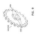
- FIG. 9shows protrusions on one of the faces of the pulley gear that is configured to slot into corresponding slotted ribs located on the center drive pulley;
- FIG. 10shows ribbed slots on the center drive pulley that are configured to receive the pulley gears
- FIG. 11shows the rack of the trigger of the delivery device
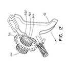
- FIG. 12shows the trigger and the drive gears
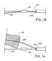
- FIGS. 13-16illustrate the steps of affixing one end of a retaining wire through the crowns of the stent
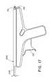
- FIG. 17is a perspective view of a handle portion of the delivery device
- FIGS. 18-21show an alternative stabilizing element for fixating the stent during the resheathing of the outer catheter
- FIG. 22shows the entire delivery device preloaded with an esophageal stent at the distal tip of the delivery section
- FIGS. 23-26show a method of use of the delivery device
- FIG. 27shows a main drive gear rotationally fixed to the drive shaft
- FIGS. 28-31show an embodiments for fixating a self-expandable stent during resheathing of the outer catheter and deployment of the stent;
- FIG. 32shows a friction mechanism for preventing premature disengagement of lockwire from stent
- FIG. 33shows a cross-sectional view of a reinforced outer sheath
- FIG. 34shows a cross-sectional view of a distal section of the outer sheath, the distal section reinforced with a coil
- FIG. 35shows a cross-sectional view of a proximal section of the reinforced outer sheath, the proximal section being reinforced with a braid;
- FIG. 36shows an overlapping section of the reinforced outer sheath in which the coil proximally extends into the proximal section of the outer sheath to overlap with the braid;
- FIG. 37shows an alternative embodiment of a pulley gear
- FIG. 38shows an alternative embodiment of a center drive pulley designed to engage with the pulley gear of FIG. 37 ;
- FIGS. 39A-40Bshow an embodiment of a delivery system having a short wire configuration
- FIGS. 41A-41Cshow an embodiment of a delivery system for a stent having delayed loading characteristics
- FIGS. 42A-42Bshow an alternative embodiment of the delivery system shown in FIGS. 41A-41C .
- distal and distalshall denote a position, direction, or orientation that is generally away from the physician. Accordingly, the terms “proximal” and “proximally” shall denote a position, direction, or orientation that is generally towards the physician.
- FIGS. 1-38a delivery device for deploying a self-expanding prosthesis is shown.
- the delivery devicehas the ability to resheath and reposition the prosthesis, thereby substantially increasing the control and accuracy of the deployment process as compared with conventional delivery devices.
- FIG. 1shows an exemplary delivery device 100 .
- the inner catheter 1207 and outer catheter 1200are shown exiting the distal end of the device 100 .
- the inner catheter 1207remains fixated to the delivery device 100 at the rear hub 104 .
- the outer catheter 1200may be affixed to a movable belt 1201 ( FIG. 4 ).
- Actuation of a spring-loaded trigger 102pulls the outer catheter 1200 in the proximal direction relative to the inner catheter 1207 to expose the self-expanding prosthesis.
- a directional switch 101may be engaged to reverse the direction of the outer catheter 1200 prior to actuating the trigger 102 .
- An internal gear-pulley mechanismenables the bidirectional movement of the outer catheter 1200 .
- FIG. 2shows the first gear set 500 .
- the first gear set 500comprises a first drive gear 502 , a first idle gear 501 , and a first pulley gear 503 .
- the first drive gear 502is mechanically engaged with the first idle gear 501 .
- the first idle gear 501is mechanically engaged with the first pulley gear 503 .
- the first drive gear 502has a one-directional roller clutch bearing 504 . Specifically, the roller clutch bearing 504 is press fit within the inner surface of the first drive gear 502 and allows for rotation of the first drive gear 502 in only one direction, which will be explained in greater detail below.
- FIG. 3shows the second gear set 400 .
- the second gear set 400comprises a second drive gear 401 and a second pulley gear 402 .
- the second drive gear 401is mechanically coupled to the second pulley gear 402 .
- the second drive gear 401Similar to the first drive gear 502 , the second drive gear 401 also comprises a roller clutch bearing 403 that allows for rotation of the gear 401 in only one direction, which will be explained in greater detail below.
- a drive shaft 702extends through the clutch bearing 403 of the second drive gear 401 ( FIG. 3 ) and through the clutch bearing 504 of the first drive gear 502 ( FIG. 2 ).
- a main drive gear 701is rotationally fixed to the drive shaft 702 , as clearly seen in FIG. 27 .
- the main drive gear 701is also engaged with a trigger 102 ( FIG. 12 ).
- the trigger 102includes a rack 709 having complimentary teeth 704 ( FIG. 11 ) that engage with the main drive gear 701 .
- Proximal and distal movement of the outer catheter 1200may be allowed by the outer catheter 1200 being connected to a belt 1201 , as shown in FIG. 4 .
- the outer catheter 1200is affixed to a shuttle 1202 and the shuttle 1202 is connected to a belt 1201 .
- FIGS. 5 and 6show how the outer catheter 1200 is affixed to the shuttle 1202 .
- FIG. 5shows that the end of the outer catheter 1200 may be flared and pushed up against the shuttle 1202 .
- FIG. 6shows that a shuttle cap 1217 may be coupled to the shuttle 1202 .
- the cap 1217may be screwed onto the threads of the shuttle 1202 to secure the outer catheter 1200 to the shuttle 1202 .
- the inner catheter 1207may be secured to the rear hub 104 in a similar manner.
- Other types of attachments of the outer catheter 1200 to the belt 1201are contemplated.
- FIG. 7shows that the shuttle 1202 contains an opening 1218 through which belt 1201 may extend.
- the shuttle 1202contains corresponding grooves 1220 that engage with protrusions 1219 of the belt 1201 to establish a secure belt-shuttle connection. Movement of the belt 1201 causes the shuttle 1202 and outer catheter 1200 attached thereto to laterally move along the belt 1201 in the proximal direction or distal direction.
- FIG. 4illustrates possible positions that the outer catheter 1200 may have.
- the most reverse position of the shuttle 1202 and belt 1201is indicated at position 1205 .
- the most forward position of the shuttle 1202 and belt 1201is indicated at position 1206 .
- the shuttle cap 1217is not shown at positions 1205 and 1206 .
- the inner catheter 1207remains stationary because the inner catheter 1207 is fixated at the proximal end of the device 100 at the rear hub 104 .
- desired belt 1201 movementis achieved by engaging a center drive pulley 901 with the first pulley gear 503 or the second pulley gear 402 .
- the first pulley gear 503 and the second pulley gear 402are slidable along a shaft to engage and disengage with the drive pulley 901 .
- the engagement and disengagementmay occur by the ribs or protrusions 1000 of the pulley gears 503 , 402 slidably engaging with the ribbed slots 902 of the center drive pulley 901 .
- Directional switch 101allows the first pulley gear 503 or the second pulley gear 402 to engage with the center drive pulley 901 .
- FIG. 8Billustrates an exemplary directional switch 101 .
- the first pulley gear 503 , second pulley gear 402 , and directional switch 101extend along a shaft (not shown). Pushing the directional switch 101 against the first pulley gear 503 causes the first pulley gear 503 to engage with the center drive pulley 901 and the second pulley gear 402 to disengage with the center drive pulley 901 along the shaft.
- the center drive pulley 901may be engaged to either the first pulley gear 503 or the second pulley gear 402 .
- the engagement of the first or second pulley gears 503 , 402 with the center drive pulley 901can be understood by referring to FIGS. 9 and 10 .
- the first and second pulley gears 503 and 402may appear as shown in FIG. 9 .
- FIG. 10shows that the center drive pulley 901 contains ribbed slots 902 that correspond to protrusions 1000 ( FIG. 9 ) of the first and second pulley gears 503 , 402 .
- the multiple side protrusions 1000 of the first and second pulley gears 503 , 402slide into the ribbed slots 902 located on the side of the center drive pulley 901 ( FIG. 10 ) to lockably engage with each other.
- the engagementmay be such that when the locked first pulley gear 503 or locked second pulley gear 402 rotates, the center drive pulley 901 will rotate in the same direction, thereby transferring the motion of the pulley gears 503 , 402 to the drive pulley 901 and belt 1201 .
- the first and second pulley gears 503 and 402may comprise a greater number of ribbed slots 902 compared to that shown in FIG. 9 to facilitate engagement of the pulley gears 503 and 402 with the center drive pulley 901 .
- the shape of the ribbed slots 902 of the center drive pulley 901may be modified to enhance its engagement with the gears 503 and 402 .
- FIG. 37shows an example of an alternative embodiment of a first and second pulley gear 3702 and 3703 having angled slots 3700 .
- the shape and greater number of slots 3700may provide improved engagement of the gears 3702 and 3703 with the center drive pulley 3801 shown in FIG. 38 .
- center drive pulley 3801contains multiple slots 3802 , each of which are defined by adjacently disposed angled structures 3803 .
- the shape of each of the slots 3802corresponds to the shape of each of the angled slots 3700 ( FIG. 37 ) to allow a secure fit therewithin.
- the belt 1201is shown in FIG. 4 to be wrapped around three pulleys 1211 , 1212 and 901 .
- Pulleys 1211 and 1212may help transfer gear movement into belt movement.
- Center drive pulley 901engages with one of the first gear set 500 and the second gear set 400 to cause rotational movement of the belt 1201 .
- a three pulley systemis shown, more than three pulleys or less than three pulleys are contemplated.
- Idlers 1215 and 1216may help to provide wrapping a sufficient amount of the belt 1201 around the center drive pulley 901 for the purpose of preventing belt 1201 slippage from the center drive pulley 901 .
- the belt 1201wraps around idler 1215 and then proceeds down and around the center drive pulley 901 .
- the belt 1201then proceeds up and around the top of idler 1216 .
- FIG. 4shows that the idlers 1215 , 1216 help the belt 1201 to wrap around more than 180° of the center drive pulley 901 .
- the gear mechanism for resheathingi.e., the outer catheter 1200 moving from the proximal direction to the distal direction as indicated by the arrow in FIG. 4
- Reference to the rotational movement of the various gears and pulleyswill be made in accordance with perspective views facing the first gear set 500 ( FIGS. 4, 8, 11, 12 ).
- the directional switch 101is pushed such that the first pulley gear 503 is engaged with the center drive pulley 901 and the second pulley gear 402 is disengaged from the center drive pulley 901 ( FIG. 8A ). Pulling the trigger 102 in the proximal direction, as indicated by the arrow in FIG.
- the main drive gear 701causes the main drive gear 701 to engage with the rack 709 ( FIG. 12 ) of the trigger 102 ( FIG. 11 ) and rotate in a clockwise direction (the three arrows in FIG. 12 around first drive gear 502 represent clockwise rotation). Because the main drive gear 701 is directly connected to the drive shaft 702 , the drive shaft 702 also rotates in a clockwise direction. As the drive shaft 702 rotates in a clockwise direction, the first drive gear 502 and the second drive gear 401 also rotate in the same direction. The first drive gear 502 is engaged to the first idle gear 501 and therefore clockwise rotation of the first drive gear 502 causes the first idle gear 501 to rotate counterclockwise ( FIG. 8A ).
- the first idle gear 501is engaged to a first pulley gear 503 . Accordingly, counterclockwise rotation of the first idle gear 501 causes the first pulley gear 503 to rotate clockwise ( FIG. 8A ). Because the directional switch 101 has been pushed to engage the first pulley 503 with the center drive pulley 901 ( FIG. 8A ), the center drive pulley 901 also rotates in the clockwise direction. With the belt 1201 winding around a center drive pulley 901 , two idlers 1215 and 1216 pull in the belt 1201 around the center drive pulley 901 , as shown in FIG. 4 .
- the idlers 1215 and 1216optimize the connection between the belt 1201 and the center drive pulley 901 to minimize slippage of the belt 1201 around the center drive pulley 901 .
- Clockwise rotation of the center drive pulley 901also causes the belt 1201 to rotate clockwise ( FIG. 4 ).
- the clockwise rotation of the belt 1201causes the shuttle 1202 and outer catheter 1200 attached thereto to resheath or move proximally to distally ( FIG. 4 ).
- the drive shaft 702 and main drive gear 701rotate counterclockwise and return to their original position.
- the drive shaft 702is permitted to rotate counterclockwise within the one-directional roller clutch bearings 403 , 504 .
- roller clutch bearings 403 , 504prevent the left and right drive gears 401 , 502 from rotating counterclockwise upon the trigger 102 being deactivated.
- the first and second drive gears 502 and 401will remain in the position from which they have rotated clockwise after activation of the trigger 102 .
- the effect of having the first drive gear and the second drive gears 502 and 401 rotate clockwise but not counterclockwiseis that the outer catheter 1200 may continue to be incrementally moved in a proximal (i.e., retractable direction) or distal direction (i.e., resheathing direction). Accordingly, this unidirectional movement of the first and second drive gears 502 and 401 is converted into movement of the belt 1201 .
- the gear mechanism for retracting the outer catheter 1200(i.e., the outer catheter 1200 moving from the distal direction to the proximal direction) will now be explained. Reference to the rotational movement of the various gears and pulleys will be made in accordance with perspective views facing the second gear set 400 ( FIG. 3 ).
- the directional switch 101is pushed such that the second pulley gear 402 is engaged with the center drive pulley 901 and the first pulley gear 503 is disengaged from the center drive pulley 901 .
- pulling the trigger 102 in the proximal direction as indicated by the arrowcauses the main drive gear 701 to engage with the rack 709 ( FIG. 11 ) of the trigger 102 and rotate in a counterclockwise direction.
- the drive shaft 702also rotates in a counterclockwise direction. As the drive shaft 702 rotates in a counterclockwise direction, the first drive gear 502 and the second drive gear 401 rotate in the same direction. Because the second drive gear 401 is engaged to the second pulley gear 402 , counterclockwise rotation of the second drive gear 402 causes the second pulley gear 402 to rotate clockwise ( FIG. 3 ). The engagement of the second pulley gear 402 with the center drive pulley 901 causes the center drive pulley 901 to also rotate in a clockwise direction ( FIG. 3 ).
- the rotation of the second pulley gear 402 with the center drive pulley 901which was seen as clockwise from the perspective in FIG. 2 , becomes viewed as counterclockwise from the perspective in FIG. 3 .
- the counterclockwise rotation of the center drive pulley 901also causes the belt 1201 to rotate counterclockwise.
- the counterclockwise rotation of the belt 1201causes the shuttle 1202 and outer catheter 1200 attached thereto to retract or move distally to proximally ( FIG. 12 ), thereby exposing the self-expanding prosthesis.
- a step 1308is formed where the smaller and larger diameter portions of the inner catheter 1207 meet, which prevents the prosthesis from being pulled back proximally with the outer sheath 1200 .
- the unidirectional movement of the first and second drive gears 502 and 401is converted into proximal movement of the belt 1201 and outer catheter 1200 attached thereto.
- the drive shaft 702 and main drive gear 701rotate clockwise with respect to FIG. 3 and return to their original position.
- the drive shaft 702is permitted to rotate clockwise within the one-directional roller clutch bearings 403 , 504 .
- roller clutch bearings 403 , 504prevent the left and right drive gears 401 , 502 from rotating upon the trigger 102 being deactivated.
- the effect of having the first drive gear and the second drive gears 502 and 401 rotate counterclockwise but not clockwise (as shown in FIG. 3 )is that the outer catheter 1200 may continue to be incrementally moved in a proximal direction (i.e., retractable direction).
- a stabilizing elementis affixed to the prosthesis.
- the stabilizing elementmaintains the prosthesis in a substantially stationary position during the resheathing of the outer catheter 1200 over the prosthesis, as will now be explained.
- FIGS. 13-16show the steps involved in loading and anchoring a preferred type of stabilizing element to a self-expanding stent.
- FIGS. 13-16show that the stabilizing element may be a retaining wire 290 .
- the proximal end of the retaining wire 290is anchored to a ring 210 at the rear hub 104 of the inner catheter 1207 , as shown in FIG. 17 .
- the wire 290extends along the longitudinal length of the device 100 .
- the proximal portion of the wire 290is disposed between the inner catheter 1207 and the outer catheter 1200 .
- FIG. 14shows that as the wire 290 emerges from the inner catheter 1207 , it passes through one of the crowns 300 of a self-expanding stent 301 .
- FIG. 14shows that the wire 290 extends distally from the end portion of the stent 301 and may terminate at the body portion of the stent 301 .
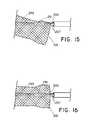
- the distal end of the wire 290is maneuvered to extend through a lumen of a piece of bilumen tubing 291 ( FIG. 15 ), which is affixed (e.g., glue) to the inner catheter 1207 .
- the smaller diameter portion of the inner catheter 1207is configured to extend through the proximal end of the stent 301 as shown in FIG. 15 .
- the distal end of the wire 290exits the lumen of the bilumen tubing 291 .
- the distal end of the wire 290is a free end that terminates within the lumen of the stent 301 , as shown in FIGS. 15 and 16 .
- the free endpreferably does not interact with the stent 301 .
- the retaining wire 290 in this configurationanchors the stent 301 in place such that the stent 301 will not move distally as the outer catheter 1200 is being resheathed over the stent 301 .
- the stent 301is locked into position at its proximal end by the crown 300 which the retaining wire 290 extends through.
- the stent 301cannot substantially move proximally because the stent 301 is locked by the wire 290 and the larger diameter portion of the inner catheter 1207 .
- the stent 301cannot substantially move distally because it is locked between the wire 290 and bilumen tubing 291 .
- the stent 301cannot substantially move up (i.e., coming out of the plane of the page) or down (i.e., going into the plane of the page) because the wire 290 passes through the crown 300 .
- the stent 301may not become free until the retaining wire 290 is removed from the crown 301 . Removal of the retaining wire 290 may be achieved by pulling the ring 210 at the rear hub 104 of the inner catheter 1207 , as shown in FIG. 17 .
- the bilumen tubing 291may be positioned anywhere along the stent 301 .
- the bilumen tubing 291is positioned toward the proximal end of the stent 301 for the purpose of maximizing resheathing capabilities of the outer catheter 1200 .
- the more the bilumen tubing 291 is positioned toward the distal end of the stent 301the greater the tendency may be for the stent 301 to move with the outer catheter 1200 during resheathing.
- FIG. 13-16the bilumen tubing 291 is positioned toward the proximal end of the stent 301 for the purpose of maximizing resheathing capabilities of the outer catheter 1200 .
- the more the bilumen tubing 291 is positioned toward the distal end of the stent 301the greater the tendency may be for the stent 301 to move with the outer catheter 1200 during resheathing.
- the bilumen tubing 291is affixed to the smaller inner catheter 1207 and positioned about 2 mm to about 5 mm from the proximal end of the stent 301 . Accordingly, the amount of lateral movement of the stent 301 during resheathing of the outer catheter 1200 may be substantially eliminated.
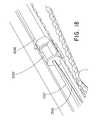
- the stabilizing elementis a suture loop 1300 may be used as shown in FIGS. 18-21 .
- the suture loop 1300may be looped through one or more crowns of the stent and is positioned in between the outer catheter 1200 and the inner catheter 1207 . It may exit the shuttle 1202 as shown in FIG. 18 .
- the suture loop 1300continues to extend inside the device 100 between the inner catheter 1207 and the outer catheter 1200 , as shown in FIG. 18 .
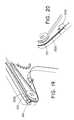
- the suture loop 1300exits the rear hub 104 as shown in FIG. 19 . After exiting the rear hub 104 , the suture loop 1300 follows a path where it is connected to the bottom of the device 100 at a post 1500 ( FIG. 20 ).
- a groove 1510FIG.
- the suture loop 1300located at the bottom of the device 100 may be used to cut the suture loop 1300 .
- the remainder of the suture loop 1300can be pulled through the device 100 by pulling on one end of the suture 1300 . Because the suture 1300 is held in place at the one or more crowns 300 of the stent and at the post 1500 of the handle ( FIG. 20 ), the stent 301 may substantially be held in place during resheathing of the outer catheter 1200 .
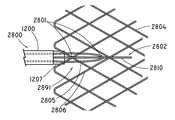
- FIGS. 28-32show an alternative embodiment of a stabilizing element used to fixate the stent 2804 to the inner catheter 1207 during resheathing (i.e., distal movement of the outer sheath 1200 relative to the inner catheter 1207 ) or deployment of the stent 2804 (i.e., proximal movement of the outer sheath 1200 relative to the inner catheter 1207 ).
- the stabilizing elementcomprises an anchorage assembly 2800 as shown in FIGS. 28 and 29A .
- FIG. 28shows that the anchorage assembly 2800 includes a retaining loop assembly 2891 and a lockwire 2802 .
- FIG. 29Ashows that the retaining loop assembly 2891 includes a retaining loop wire 2930 , a first pair of cannulas 2902 and 2904 , and a second cannula 2903 .
- FIG. 28shows that the stent 2804 is anchored to the inner catheter 1207 by engagement of a lockwire 2802 through the retaining loop wire 2930 , and the struts 2805 and 2806 of the stent 2804 .
- the lockwire 2802comprises a distal portion 2810 ( FIGS. 28 and 30 ) and a proximal portion 2811 ( FIG. 30 ).
- FIG. 30shows that the proximal portion 2811 of the lockwire 2802 extends proximally between the inner catheter 1207 and the outer sheath 1200 and terminates as a pigtail 2401 at the rear hub 104 of the handle of the device 100 ( FIG. 24 ).
- FIGS. 28 and 30show that the distal portion 2810 of lockwire 2802 distally extends out from between the outer sheath 1200 and the inner catheter 1207 towards the stent 2804 .
- the distal portion 2810shows that as the distal portion 2810 emerges from inner catheter 1207 , the distal portion 2810 extends along an outside portion of stent 2804 in a distal direction and passes over the first strut 2805 of the stent 2804 . After passing over the first strut 2805 , the distal portion 2810 distally travels from the outside portion of the stent 2804 to the inside of the stent 2804 , the distal portion 2810 of lockwire 2802 now being disposed within the luminal space of the stent 2804 .
- the distal portion 2810 of lockwire 2802extends in the distal direction past second strut 2806 and through the retaining loop wire 2930 from the outside to the inside and past the apex 2931 ( FIG. 29A ) of retaining loop wire 2930 .
- the distal portion 2810 of lockwire 2802continues to travel a predetermined distance within luminal space of stent 2804 and eventually terminates as a distal free end (not shown) within the luminal space of stent 2804 .
- the distal portion 2810 of the lockwire 2802releasably locks the stent 2804 to the inner catheter 1207 .
- the points at which the lockwire 2802 , the retaining loop wire 2930 , and the first strut 2805 of stent 2804 intersect each otherdefines anchorage points 2801 .
- the stent 2804remains substantially fixated to inner catheter 1207 at anchorage points 2801 during resheathing of outer sheath 1200 and also during deployment of the stent 2804 .
- the stent 2804remains locked to the inner catheter 1207 by anchorage assembly 2800 (i.e., retaining loop assembly 2891 and lockwire 2802 ).
- anchorage assembly 2800i.e., retaining loop assembly 2891 and lockwire 2802
- the force generated and imparted to the retaining loop assembly 2891 during resheathingcan rise to about 70 Newtons of axial load during use without breakage, as shown in FIG. 31 . Accordingly, it is necessary for the retaining loop assembly 2891 to maintain anchorage of the stent 2804 at such relatively high loads. Failure for the retaining loop assembly 2891 to fixate the stent 2804 at such high loads may cause the stent 2804 to slip along the inner catheter 1207 such that resheathing and/or deployment capabilities are lost.
- FIG. 29shows more clearly the components of the retaining loop assembly 2891 which are designed to withstand such loads.
- the retaining loop wire 2930is inserted into the first pair of cannulas 2902 and 2904 .
- the first pair of cannulas 2902 and 2904is shown connected to the second cannula 2903 .
- Numerous meansmay be used to connect the first pair of cannulas 2902 and 2904 with second cannula 2903 .
- the first pair of cannulas 2902 and 2904may be connected to the second cannula 2903 by an adhesive.
- the first pair of cannulas 2902 and 2904is laser welded to the second cannula 2903 .
- the distal portion 2932 of the retaining loop wire 2930forms its loop shape.
- the distal portion 2932 of the wire 2930folds back upon itself to form two proximal sections 2934 and 2935 , each of which is shown to extend completely through corresponding openings 2955 and 2956 of the first pair of cannulas 2902 and 2904 .
- the proximal sections 2934 and 2935 of retaining loop wire 2930are affixed within the inside of corresponding openings 2955 and 2956 of the first pair of cannulas 2902 and 2904 at proximal end 2950 , preferably by a spot weld.
- strain release of retaining loop wire 2930occurs which enables substantial flexing of the loop wire 2930 without breakage.
- each of the cannulas 2902 , 2903 , 2904 and the retaining loop wire 2930are preferably formed from materials sufficient to enable the retaining loop assembly 2891 to withstand the forces associated with pushing the outer sheath 1200 over the inner catheter 1207 during the resheathing procedure or withdrawing the outer sheath 1200 over the inner catheter 1207 .
- each component of the retaining loop assembly 2891i.e., the first pair of cannulas 2902 and 2904 , the second cannula 2903 , and the retaining loop wire 2930
- a metallic alloysuch as, for example, ASTM grade 302 or 304 stainless steel, which can withstand up to about 70 Newtons of axial load without breakage.
- the tensile strength of the retaining loop wire 2930is preferably designed to range between 200 to 300 kpsi in order to accommodate for the 70 N load which may be created against retaining loop assembly 2891 by distal movement of the outer sheath 1200 relative to the inner catheter 1207 .
- the first pair of cannulas 2902 , 2904 , the second cannula 2903 and the retaining loop wire 2930may be formed from any other suitable biocompatible material known in the art.
- the first pair of cannulas 2902 and 2904 and/or the second cannula 2903may be formed from a high strength biocompatible polymeric material capable of withstanding the high loads which can occur during resheathing of outer sheath 1200 .
- the first pair of cannulas 2902 and 2904may be formed from polyetheretherketone (PEEK) and similar polymers.
- FIG. 29BAn alternate embodiment of an anchorage assembly 2960 including a retaining loop 2962 and a lockwire 2964 is shown in FIG. 29B .
- the anchorage assembly 2960includes a first cannula 2968 , a pair of retaining loop cannulas 2970 , 2972 and a lockwire cannula 2974 .
- the retaining loop wire 2962may be inserted into the retaining loop cannulas 2970 and 2972 forming a loop and the lockwire 2964 may be extended through the lockwire cannula 2974 so that the lockwire 2964 extends past the retaining loop 2962 to releasably lock the retaining loop with the stent 2804 .
- the lockwire 2964may be woven over a strut 2805 of the stent 2804 and under the retaining loop wire 2962 as shown in FIG. 29B .
- the lockwire 2964may be woven under a strut 2805 of the stent 2804 and over the retaining loop wire 2962 .
- the pair of retaining loop cannulas 2970 , 2972 and a lockwire cannula 2974are shown connected to the first cannula 2968 .
- the connectionmay be formed by any method known to one skilled in the art such as described above the first pair of cannulas 2902 and 2904 . Because the retaining wire is connected only at the cannulas 2968 , 2970 , strain release of retaining loop wire 2962 occurs which enables substantial flexing of the loop wire 2962 without breakage.
- FIG. 30is an expanded view of the distal portion of the device 100 disposed distal of the handle.
- FIG. 30shows the outer sheath 1200 partially disposed over the inner catheter 1207 .
- the distal region of the inner catheter 1207 as showncontains four sections. Section 1206 of inner catheter 1207 extends along the proximal direction into the handle of the device 100 and constitutes the majority of longitudinal length of inner catheter 1207 .
- Section 1210is the smallest diameter portion of the inner catheter 1207 and represents the region where stent 2804 is loaded therealong. Minimizing the diameter of inner catheter 1207 to that of section 1210 enables loading a larger diameter self-expandable stent 2804 which in turn provides a larger radial force when deployed at a target stricture. A sufficient radial force is necessary for self-expandable 2804 to maintain patency within the lumen of the target stricture and not migrate away from the stricture due to peristalsis effects which occur in the gastrointestinal tract.
- the proximal end of the section 1210partially extends into section 1206 (e.g., about 15 mm) to ensure sufficient attachment there between.
- Section 1208represents the distal portion of section 1206 .
- Section 1208is flared outwards a sufficient amount to prevent distal movement of the second cannula 2903 of the retaining loop assembly 2891 .
- the size of the flare of the section 1208is greater than the inner diameter of the second cannula 2903 .
- other sizes of the cannula 2903 and the flare of the section 1208may be used.
- Retaining loop assembly 2891is disposed over section 1206 and abutted against flared section 1208 where it is affixed by any means known in the art, such as, for example, an adhesive.
- the flared section 1208prevents the second cannula 2903 of retaining loop assembly 2891 from moving in the distal section towards stent pusher section 1209 .
- the retaining loop wire 2930is shown in FIG. 30 to extend slightly distally of distal end of the pusher section 1209 .
- Distal portion 2810 of lockwire 2802is shown emerging from within the outer sheath 1200 and section 1206 of inner sheath 1207 .
- the retaining loop wire 2930is configured to be disposed within the lumen of stent 2804 as shown in FIG. 28 .
- the distal portion 2810 of the lockwire 2802is configured to emerge from within the outer sheath 1200 and section 1206 of inner catheter 1207 and engage with the retaining loop wire 2930 and strut 2805 of stent 2804 at anchorage points 2801 , as shown in FIG. 28 .
- the stent 2804 in its loaded configurationwill be disposed over section 1210 of inner catheter and abutted against stent pusher section 1209 ( FIG. 30 ).
- a frictional mechanismmay be incorporated to prevent premature disengagement of the lockwire 2802 with the retaining loop wire 2930 and the strut 2806 at anchorage point 2801 .
- a static tube 3200may serve as the frictional mechanism.
- the static tube 3200is preferably disposed at the distal end of the handle of device 100 ( FIG. 1 ) and coaxially between outer sheath 1200 and section 1206 of inner catheter 1207 .
- FIG. 32shows a side profile of an exemplary static tube 3200 .
- the static tube 3200has a predetermined longitudinal length. Any means may be used to affix static tube 3200 between outer sheath 1200 and section 1206 of inner catheter 1207 , including, for example, an adhesive or a mechanical connector.
- a predetermined number of slits 3210are created within the wall of static tube 3200 into which the lockwire 2802 loops or weaves in and out. This weaving of the lockwire 2802 increases the frictional force required for pulling the lockwire 2802 out from the slits 3210 of static tube 3200 .
- the static tube 3200may substantially prevent the lockwire 2802 from inadvertently slipping proximally or distally between the inner catheter 1207 and the outer sheath 1200 .
- the lockwire 2802remains stationary at the anchorage point 2801 until it is intended to be proximally pulled therefrom.
- Such a frictional mechanismmay be conducive when delivery and deployment of stent 2804 is occurring within tortuous body pathways.
- Disengagement of the lockwire 2802occurs when the stent 2804 is ready to be fully deployed at a target site within a body lumen.
- Directional switch 101( FIG. 1 ) is pressed to actuate the second gear set 400 ( FIG. 3 ) to enable proximal retraction of the outer sheath 1200 relative to the inner catheter 1207 .
- trigger 102is actuated multiple times to retract the outer sheath 1200 in the proximal direction relative to the inner catheter 1207 until the stent 2804 has fully radially expanded.
- FIG. 24shows that the proximal portion of the lockwire 2802 extends proximally between the inner catheter 1207 and the outer sheath 1200 and terminates as a pigtail 2401 at the rear hub 104 of the handle of the device 100 .
- the pigtail 2401is pulled so as to remove lockwire 2802 in a proximal direction from anchorage point 2801 .
- the lockwire 2802is completely removed from device 100 , thereby disengaging the stent 2804 from section 1210 ( FIG. 30 ) of inner catheter 1207 .
- the stent 2804is completely deployed within the body lumen.
- the stabilization embodiment described above in conjunction with FIGS. 28-32provides many advantages described below with reference to the retaining loop assembly 2891 and also applicable to the alternate embodiments described herein.
- the retaining loop assembly 2891does not substantially increase the lateral profile of outer catheter 1200 and inner catheter 1207 , thereby enabling through the scope (TTS) self-expandable stents, such as duodenal and colonic stents, to be advanced through an endoscopic accessory channel, which typically has a diameter of about 3.7 mm or less.
- TTSscope
- the retaining loop assembly 2891is designed and constructed to withstand the large axial loads ( FIG.
- the retaining loop wire 2930is shown anchored to stent 2804 more proximally compared to the bilumen tubing 291 stabilization element, thereby allowing a smaller lateral profile of inner catheter 1207 in the region that the stent 2804 is loaded.
- Incorporation of the static tube 3200 described abovealso prevents premature disengagement of the stabilization elements.
- the static tube 3200enables lockwire 2802 to remain stationary at the anchorage point 2801 to fixate the stent 2804 to inner catheter 1207 until the stent 2804 is intended to be fully deployed and therefore disengaged from inner catheter 1207 .
- a delivery device 4000is shown in FIG. 39A in a short wire configuration including an inner catheter 4010 , an outer sheath 4012 and an exchange port 4014 at a distal portion 4016 of the delivery device 4000 .
- a guide wire 4018is insertable through the exchange port 4014 at the distal portion 4016 and exits the delivery device 4000 through a distal port 4020 .
- the short wire configuration of the delivery device 4000allows the guide wire 4018 to be inserted into the exchange port 4014 that is distal to a handle entry port used in an over-the-wire configuration described above.
- the delivery device 4000is configured to allow the guide wire 4018 to exit the distal port 4020 in a direction that is substantially parallel to a main axis 4022 of the delivery device 4000 to improve trackability and delivery through an endoscope that is difficult when the guide wire 4018 is provided at an angle to main axis 4022 .
- the delivery device 4000is provided with a handle 4024 at a proximal portion 4026 .
- the handle 4024may function similarly to the embodiments described above and shown for example in FIGS. 1-12 .
- a retaining wire (not shown) similar to the embodiments described abovemay also be used with the delivery device 4000 that is insertable through the handle 4024 and provided to releasably hold a stent 4004 to the inner catheter 4010 .
- FIG. 39BAn enlarged view of the distal portion 4016 of the delivery system 4000 is shown in FIG. 39B , where the stent 4004 is positioned on the inner catheter 4010 and the guide wire 4018 is shown inserted into the exchange port 4014 and exiting the distal port 4020 .
- FIGS. 40A and 40Billustrate embodiments of the inner catheter 4010 and the outer sheath 4012 , respectively, of the short wire configuration for the delivery device 4000 .
- a lockwire port 4044is shown at the proximal portion 4026 of the delivery device 4000 and the exchange port 4014 and distal port 4020 are shown at the distal portion 4016 .
- the inner catheter 4010may include an anchorage assembly at the distal portion 4016 , such as the anchorage assembly 2960 as shown in FIG. 29B , to hold the stent 4004 to the inner catheter as the outer sheath 4012 is proximally withdrawn and distally replaced over the stent.
- the outer sheath 4012 having a short wire configuration with the distal exchange port 4014is shown in FIG.
- the guide wire 4018may be inserted into the exchange port 4014 in the outer catheter 4012 and the inner catheter 4010 and out of the distal port 4020 . Similar to the embodiments described above, the stent 4004 may be resheathed by the outer catheter 4012 while the stent 4004 is held in position over the inner catheter 4010 by the anchorage assembly 2960 .
- TTS self-expandable stentsfor deployment within the gastrointestinal tract necessitates that the outer sheath and inner catheter be sufficiently small in size to fit through an accessory channel of an endoscope. Additionally, because the tumor within the gastrointestinal tract is often situated in difficult-to-access regions (e.g., ascending colon or duodenum), the outer sheath and inner catheter should be sufficiently flexible but yet kink resistant and pushable to navigate to these difficult-to-access regions. Notwithstanding these desirable attributes of the outer sheath and inner catheter, the extent to which the lateral profile of the outer sheath may be decreased will be limited by the radial force the TTS self-expandable stent is required to exert at the target stricture.
- Outer sheaths which are too thinmay not have sufficient mechanical strength to deploy a TTS stent because the TTS stent needs to exert a radial force sufficient to maintain patency at the stricture and remain anchored therewithin so as to be resistant to any tendency to migrate away from the stricture due to peristalsis effects. Therefore, generation of sufficient radial force at a target stricture requires deploying a TTS stent with the largest possible radial force.
- thin sheathsmay experience higher stress levels during deployment (i.e., the forces required at the handle of the device 100 to proximally pull the outer sheath 1200 relative to inner catheter 1207 to fully expose the stent 2804 ) and during resheathing (i.e, the forces required at the handle of the device 100 for distally pushing the outer sheath 1200 relative to the inner catheter 1207 to fully reheat the inner catheter 1207 ) compared to larger sheaths.
- the higher forces required for resheathing or deployment of outer sheathcan be burdensome.
- the outer diameter of the outer sheathis limited by the size of the accessory channel on the endoscope and reducing the inner diameter of the outer sheath limits the amount of radial force of a TTS stent that can be loaded and deployed. As mentioned, large radial forces are required to maintain patency of a target stricture and prevent migration of the stent due to peristalsis effects occurring in the gastrointestinal tract.
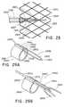
- FIGS. 33-36depict a reinforced outer sheath 3300 .
- the outer sheath 3300preferably spans a longitudinal length sufficient to deploy a TTS stent into the gastrointestinal tract. In one example, the longitudinal length of the outer sheath 3300 is about 240 centimeters.
- the outer sheath 3300includes proximal reinforced section 3301 and a distal reinforced section 3302 .
- the proximal reinforced section 3301is shown in FIG. 33 to extend from a distal end of the handle 110 of device 100 and comprises about 90% of the overall longitudinal length of the reinforced outer sheath 3300 .
- the proximal reinforced section 3301is reinforced by a braid 3316 which extends throughout the entire proximal reinforced section 3301 .
- the distal reinforced section 3302comprises about 10% of the overall longitudinal length of the reinforced outer sheath 3300 and is defined as the region of the sheath 3300 within which a self-expandable stent 2804 (not shown) can be disposed.
- the distal reinforced section 3302is reinforced by a coil 3314 .
- the coil 3314is preferably configured in a radially expanded condition and longitudinally extends along distal reinforced section 3302 and subsequently terminates at a distance away from distal tip 3366 ( FIG. 33 ).
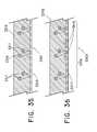
- FIG. 35shows an expanded view of the proximal reinforced section 3301 .
- FIG. 35shows that the proximal reinforced section 3301 comprises an outer layer 3318 and an inner layer 3319 .
- the braid 3316is embedded between the outer layer 3318 and the inner layer 3319 .
- the braid 3316is shown to comprise the multiple crossed wires 3317 of circular cross-sectional shape.
- the braid 3316may also comprise multiple crossed wires 3317 of any cross-sectional shape.
- the wires 3317may be formed from several types of gauge material having various cross sectional shapes. Suitable dimensions of wires 3317 may vary depending on the particular application.
- the wires 3317are formed from 0.003′′ gauge stainless steel ASTM 302 or 304 round wire having a minimum tensile strength of 128 kPSI.
- Other medical grade materialsare contemplated and may also be useful for the wires 3317 .
- the wires 3317 of braid 3317may be formed from a shape memory metallic alloy.
- the outer layer 3318contacts the braid 3316 as shown in FIG. 35 .
- the outer layer 3318preferably is formed from a polymeric material, such as polyurethane or nylon, which is preferably of a relatively higher durometer than the outer layer 3303 of the distal section 3302 ( FIG. 34 ).
- the higher durometerprovides increased resistance to stretching, which may be especially problematic when proximal section 3301 is being navigated through tortuous body lumens.
- the outer layer 3318comprises nylon.
- the nylon outer layer 3318preferably comprises blue color pigment which enhances its visibility when viewed under an endoscope. Braid 3316 in combination with the higher durometer nylon outer layer 3318 may increase the column strength of the proximal section 3301 relative to non-reinforced sheaths.
- Inner layer 3319is preferably formed from a lubricious material such as polytetrafluoroethylene (PTFE).
- PTFEpolytetrafluoroethylene
- the lubricious inner layer 3319creates a slippery surface along the inner diameter of reinforced outer sheath 3300 which may facilitate proximal and distal movement of reinforced outer sheath 3300 relative to inner sheath 1207 during resheathing or complete deployment of stent 2804 .
- Other medical grade lubricious materials known in the artare also contemplated.
- FIG. 34shows that the distal reinforced section 3302 comprises an outer layer 3303 and an inner layer 3304 .
- the coil 3314may be formed from multiple wires.
- the coil 3314is formed from a single wire wound in a helical manner.
- the coil 3314comprise multiple flat wire elements 3310 (shown in cross section in FIG. 34 ), and is preferably formed from a medical grade metal alloy, such as, for example, shape memory metal alloys.
- the coil 3314may be formed from 0.003′′ thick by 0.012′′ wide flat rectangular ASTM 302 or 304 stainless steel wire which is wound with a substantially constant spacing between the flat wire elements 3310 .
- the spacingis preferably sufficient so that the sheath 3300 along the distal reinforced section 3302 is at least semi-transparent to enable the stent to be visible within the distal section 3302 .
- the coil 3314may comprise a suitable helical pitch of about 0.045 inches, plus or minus 0.005 inches.
- the coil 3314preferably does not extend to the distal edge of distal section 3302 . Rather, the coil 3314 terminates proximal to the distal tip 3366 as shown in FIG. 33 to ensure that the coil 3314 does not become exposed beyond the distal end of distal tip 3366 .
- the flat wire elements 3310are embedded between the outer layer 3303 and the inner layer 3304 .
- the outer layer 3303is shown in FIG.
- the outer layer 3303preferably maintains the flat wire elements 3310 of coil 3314 in at least a partially radially expanded and stressed configuration between the outer layer 3303 and inner layer 3304 .
- the outer layer 3303is affixed to the flat wire elements 3310 of coil 3314 by adhesion, such as, for example, by thermal bonding to the flat wire elements 3310 .
- coil 3314is shown as having rectangular shaped flat wire elements 3310 , other shapes of flat wire elements 3310 are contemplated and may be utilized.
- the outer layer 3303preferably is formed from a polymeric material, such as nylon, which is preferably of a relatively lower durometer than the outer layer 3318 of the proximal section 3301 .
- a polymeric materialsuch as nylon
- Making the distal section 3302 of outer layer 3303 from a relatively lower durometer nylon as compared to the proximal section 3301creates a reinforced outer sheath 3300 having a distal section 3302 and distal tip 3366 that is more flexible than the proximal section 3301 .
- the nylon outer layer 3303preferably comprises a transparent pigment which enables the stent 2804 to be visible within the distal section 3302 through the endoscope.
- Inner layer 3304is preferably formed from a lubricious material such as polytetrafluoroethylene (PTFE).
- PTFEpolytetrafluoroethylene
- the lubricious inner layer 3304creates a slippery surface which facilitates loading and deployment of stent 2804 between the reinforced outer sheath 3300 and section 1210 of inner catheter 1207 along distal section 3302 .
- the inner PTFE liner of sheath 3300reduces the force needed to proximally and distally move outer sheath 3300 relative to inner sheath 1207 .
- Other medical grade lubricious materials known in the artare also contemplated.
- the reinforced coil 3314 disposed along distal section 3302provides several benefits.
- the coil 3314is designed with a predetermined number of windings per length which provides increased hoop strength of the distal section 3302 compared to non-reinforced sheaths.
- Hoop strength as used hereinrefers to the ability of the distal section 3302 of sheath 3300 to maintain its structural integrity and resist deformation incurred by the relatively high radial forces imparted by a loaded TTS stent within the distal section 2804 .
- the hoop strength of coil 3314may also reduce the deployment forces generated during resheathing and/or stent deployment operations.
- the increased hoop strength provided by coil 3314reduces the tendency for loaded TTS stent to bite into the wall of the reinforced outer sheath 3300 , thereby reducing the deployment and resheathing forces compared to non-reinforced sheaths.
- the increase in hoop strength of sheath 3300 contributed by coil 3314may be significant.
- the absence of the coil 3314would require increasing the wall thickness of the sheath 3300 along the distal section 3302 to such an extent that the profile of sheath 3300 would be too large to fit within a conventional endoscopic accessory channel having a diameter of about 3.7 mm or less.
- the structure of coil 3314enables advancement of distal section 3302 through tortuous body lumens.
- the helical windings of coil 3314 along distal section 3302enable section 3302 of outer sheath 3300 to contour into various tortuous positions of such body lumens without undergoing significant kinking.
- FIG. 36shows that that the flatwire elements 3610 of coil 3314 overlap a predetermined amount into the proximal section 3301 .
- Overlap section 3303represents a longitudinal portion of reinforced outer sheath 3300 along the proximal section 3301 that comprises both the coil 3314 and the braid 3316 .
- the overlap section 3301may be any length to ensure sufficient anchorage. In one example, the overlap section 3301 is about 1 cm.
- the attachment of the proximal portion of coil 3314 with the distal portion of braid 3316may be achieved in numerous ways, including adhesion or mechanical affixation.
- the overlap of coil 3314 with braid 3316 at overlap section 3303ensures sufficient anchorage between the two such that there are no weak points along outer sheath 3300 .
- the overlap section 3303comprises physical properties of both the proximal section 3301 that is reinforced with braid wire 3316 and the distal section 3302 that is reinforce with coil 3314 . Failure to create such an anchorage of braid 3316 and coil 3314 at overlap section 3303 may create a gap along the outer sheath 3300 in which no coil 3314 or braid 3316 exists, thereby creating a weak point which may be subject to kinking or subject to damage.
- the overlap section 3303also helps to facilitate a gradual transition in physical properties from the proximal section 3301 to the distal section 3302 . As shown in FIG. 36 , the coil 3314 is wound around the braid 3316 at overlap section 3303 . Alternatively, the braid 3316 may be wound around the coil 3314 at the overlap section 3303 .
- Assembly of reinforced outer sheath 3300preferably occurs over a mandrel.
- the PTFE inner liner 3319 of proximal section 3301 ( FIG. 35 ) and PTFE inner liner 3304 of distal section 3302 ( FIG. 34 )are preferably a single piece of material extending along the length of the outer sheath 3300 .
- the PTFEis placed over the mandrel.
- the braid 3316is slid over the PTFE.
- the braid 3316is positioned over the mandrel at the proximal section 3301 of the outer sheath 3300 .
- the coil 3314is also slid over the mandrel.
- the coil 3314is positioned such that a proximal end 3377 ( FIG.
- the coil 3314overlaps (e.g., about 1 cm) into the proximal portion 3301 where the braid 3316 is disposed to create the overlap section 3303 .
- the nylon outer layer 3318 of proximal section 3301is slid onto the proximal section of the mandrel and the nylon outer layer 3303 of distal section 3302 is slid onto the distal section of the mandrel.
- a heat shrinkable tubingmay then be disposed over all of these components which are now positioned as desired over the mandrel.
- the mandrel and the components disposed thereonare heated to a temperature sufficient to shrink and cure the heat shrinkable tubing, thereby causing it to thermally bond over the braid 3316 and coil 3314 .
- the inner PTFE liner, coil 3314 and braid 3316 reinforcement components, and outer nylon layers 3303 and 3318become thermally fused to each other.
- the mandrel and newly formed reinforced outer sheath 3300are then ambient cooled, and the heat shrinkable tubing is removed from the mandrel.
- proximal section 3301 and distal section 3302have been described as being reinforced with braid 3316 and coil 3314 respectively, it should be understood that other means for achieving the desired properties (e.g., enhanced flexibility, tensile strength, hoop strength, column strength, and kink resistance) in each of the sections 3301 and 3302 are contemplated.
- the proximal and distal sections 3301 and 3302may comprise different composites of outer materials with varying thicknesses which are individually fabricated and thereafter joined to exhibit the desired physical properties and transition in properties as needed from proximal region of outer sheath to an overlapping section to distal region of outer sheath.
- reinforced sheath 3300has been described for delivery and deployment of stents into the colonic and duodenal regions, other TTS stents may be deployed. Additionally, the reinforced sheath 3300 may be modified for suitable use with non-TTS stents. For example, the sheath 3300 may be used to deliver and deploy an esophageal stent.
- the device 100may be used to deploy various prostheses.
- a method of deploying an esophageal stent 301will now be described.
- the esophageal stent 301is loaded in between the inner catheter 1207 and the outer catheter 1200 along the distal end 1700 of the device 100 , as shown in FIG. 22 .
- Part of the loading process of the stent 301involves affixing retaining wire 290 from one of the crowns 300 at the proximal end of the stent 301 to the rear hub 104 located at the proximal end of the device 100 , as was described and shown in FIGS. 13-16 .
- a stent 5004 provided for use with any of the delivery systems described abovemay be loaded into the delivery system just prior to insertion of the stent 5004 into the patient.
- the stent 5004may be a biodegradable stent having properties that prevent the stent 5004 from being preloaded into the delivery system at the manufacturer and stored in a compressed configuration.
- An exemplary embodiment of a delivery system 5000is shown in FIG. 41A for use with the stent 5004 that is loaded onto the delivery system 5000 at the time of the patient procedure.
- the delivery system 5000is similar to the delivery systems described above and includes a funnel shaped member 5015 for loading the stent 5004 positioned around an inner catheter 5010 into an outer sheath 5012 .
- the stent 5004is in an expanded configuration 5030 around the inner catheter 5010 and positioned between a distal tip 5032 and a holder device 5034 .
- the delivery system 5000may also include a pusher catheter 5036 proximal to the holder device 5034 .
- a proximal portion 5036 of the stent 5004may be collapsed around the holder device 5034 and the proximal portion 5036 of the stent 5004 proximally drawn toward the funnel shaped member 5015 .
- FIG. 41BA partially collapsed stent 5004 is shown in FIG. 41B with the proximal portion 5036 withdrawn into the outer sheath 5012 .
- a handle similar to the embodiments described above for moving the inner catheter relative to the outer sheathmay be used to move the inner catheter 5010 and the outer sheath 5012 axially relative to each other to position the outer sheath 5012 over the stent 5004 .
- FIG. 41Cillustrates the stent 5004 fully loaded into the delivery system 5000 with a distal end 5040 of the sheath 5012 abutting the distal tip 5032 of the inner catheter 5010 to form a smooth outer surface 5042 .
- the funnel 5015is removed from the delivery system 5000 with the stent 5004 fully loaded and ready to be delivered to the patient as shown in FIG. 41C .
- the holder device 5034may be used to hold the proximal portion 5036 of the stent 5004 between the inner catheter 5010 and the outer sheath 5012 as the outer sheath 5012 is proximally withdrawn to expose the stent 5004 at the patient delivery site. Similar to the preloaded stents described above, the stent 5004 may be resheathed with the outer sheath 5012 when up to about 90-95% of the stent 5004 has been unsheathed. The holder device 5034 may be used to retain the remaining 5-10% of the proximal portion 5036 of the stent 5004 under constraint by the outer sheath 5012 .
- the delivery system 5000may also be provided with an anchorage assembly 5048 as shown in FIGS. 42A and 42B releasably holding the stent 5004 to the inner catheter 5012 .
- the anchorage assembly 5048may include a proximal suture loop 5050 and/or a proximal locking wire 5052 as shown in FIGS. 42A and 42B .
- the delivery system 5000may also be provided with a distal suture loop and/or locking wire (not shown) that operate similarly to the proximal suture loop 5050 and/or the proximal locking wire 5052 .
- the delivery system 5000may also be provided with an anchorage assembly including a retaining loop as described above for releasably holding the stent 5004 to the inner catheter 5012 .
- the stent 5004may be provided in the expanded configuration 5030 to be collapsed onto the inner catheter 5010 just before the stent 5004 is delivered to the patient.
- the stent 5004may be stored and shipped in the expanded configuration 5030 and held to the inner catheter 5010 during that time using the anchorage assembly 5048 including a suture loop 5050 woven through the stent 5004 to loosely hold the stent 5004 on the inner catheter 5010 .
- An enlarged view of the anchorage assembly 5048 without the stentis shown in FIG. 42B including the lockwire 5052 that will be woven between the stent 5004 and the suture loop 5050 for delivery.
- the suture loop 5050may be fixed to the inner catheter 5010 or the optional pusher catheter 5036 as shown in FIG. 42B .
- the suture loop 5050may also be provided through a lumen within the delivery system 5000 and connected to the stent 5004 .
- the funnel 5015is included and a proximal portion 5056 of the funnel 5015 is temporarily positioned at the distal end 5040 of the outer sheath 5012 .
- the proximal portion 5056 of the funnel 5015may be sized so that the proximal portion 5056 is slightly small than the distal end 5040 of the outer sheath 5012 so that the outer sheath 5012 slides over the proximal portion of the stent 5004 as the inner catheter 5010 and the outer sheath 5012 are moved axially relative to each other.
- the anchorage assembly 5048may be used to hold the stent 5004 in position as the stent 5004 is covered by the outer sheath 5012 .
- the stent 5004may be repeated sheathed and unsheathed.
- the anchorage assembly 5048may be released from the stent once the stent is covered by outer sheath or later, when the stent 5004 is ready for complete deployment within the patient.
- the lockwire 5052may be connected to a handle 5060 at a proximal portion 5062 of the delivery device 5000 .
- the lockwire 5052may be proximally withdrawn to release the stent 5004 from the suture loop 5050 and the inner catheter 5010 .
- the delivery device 100comprises a stent delivery section 1702 and an external manipulation section 1703 .
- the delivery section 1702travels through the body lumen during the procedure and delivers the prosthesis to a desired deployment site within the esophagus.
- the external manipulation section 1703stays outside of the body during the procedure.
- the external manipulation section 1703includes trigger 102 and can be manipulated by the physician with a single hand ( FIG.
- FIG. 23indicates that the shuttle 1202 is positioned near the distal end of the external manipulation section 1703 .
- the physicianmay grasp the trigger 102 of the device 100 with a single hand, as shown in FIG. 23 , to actuate the trigger 102 for the first time.
- the other handmay be free to perform other tasks.
- FIG. 24indicates that the trigger 102 has been completely pulled backed in the proximal direction. In particular, the tip of the shuttle 1202 has proximally moved after one actuation of the trigger 102 .
- trigger 102is actuated multiple times to retract the outer catheter 1200 in the proximal direction relative to the inner catheter 1207 until a portion of the esophageal stent 301 has become exposed and partially radially expanded, as shown in FIG. 25 . Further actuations of the trigger 102 cause the outer sheath 1200 to proximally move back even further, thereby exposing an increasing portion of the self-expanding stent 301 , as shown in FIG. 26 .
- the device 100may be activated to resheath the outer catheter 1200 over the stent 301 to allow repositioning of the stent 301 within the esophagus.
- the physicianmay need to resheath and reposition the stent 301 as a result of having placed the stent 301 in the incorrect position.
- the directional switch 101may be pressed to disengage the center drive pulley from the second pulley gear and to engage the center drive pulley with the first pulley gear ( FIG. 8A ).
- actuation of the trigger 102 one or more timesenables the outer sheath 1200 to move distally and resheath over the stent until the stent 301 is fully constrained back within the outer sheath 1200 .
- the external manipulation section 1703may be maneuvered to reposition the delivery section 1702 within the body lumen.
- the directional switch 101may be reconfigured to reactivate the second gear set 400 with the center drive pulley 901 such that proximal retraction of the outer sheath 1200 occurs, thereby exposing the stent 301 .
- the retaining wire 290retains the stent 301 and prevents it from moving distally during resheathing.
- the distal end 1700 of the outer catheter 1200may comprise a transparent or translucent material (or a light-transmitting material) to enable the physician to visually observe the stent 301 and how it is positioned in relation to the esophageal stricture.
- FIG. 17shows that the top-most portion of the shuttle 1202 protrudes through the housing of the device 100 .
- the top-most portion of the shuttle 1202proximally moves back as the outer catheter 1200 is proximally retracted and may be used as a visual indicator to determine when resheathing capabilities have been lost.
- the distance that the top-most portion of the shuttle 1202 proximally moves backcorresponds to the distance that the outer catheter 1200 has proximally retracted.
- the top-most portion of the shuttle 1202can proximally move back a predetermined threshold distance beyond which the physician will realize that the outer catheter 1200 cannot be proximally retracted any further without losing the ability to resheath and recapture the stent 301 within the outer catheter 1200 .
- the point at which the top-most portion of the shuttle 1202 aligns with a predetermined visual marker on the outer housing of the device 100can also indicate the loss of the ability to resheath.
- one or more radiopaque markers 1721may be used under fluoroscopy to determine the distance the outer catheter 1200 has proximally retracted ( FIG. 22 ).
- the radiopaque marker 1721may be placed on the outer catheter 1200 between the distal tip 1722 and the distal end 1700 of the clear portion of the outer catheter 1200 , as shown in FIG. 22 .
- the one or more markers 1721may be utilized to determine when the resheathing capabilities have been lost. For example, as the outer catheter 1200 is proximally retracted, the radiopaque marker 1721 may move along with it.
- the marker on the inner catheter 1207FIG.
- the physicianwill realize that the stent 301 cannot be exposed any further without losing the ability to resheath and recapture the stent 301 within the outer catheter 1200 .
- the device 100is capable of incrementally deploying the stent 301 .
- one full actuation of the trigger 102may proximally move the belt 1201 and hence the outer sheath 1200 from about 5 mm to about 10 mm.
- Such incremental deploymentmay facilitate greater accuracy in positioning of the stent 301 at the target region.
- a conventional push-pull delivery devicehas less control as compared to the delivery device 100 because the conventional push-pull delivery device cannot withdraw the outer sheath in such small, precise increments.
- Conventional push-pull delivery devicesrequire the user to maintain one portion of the handle in a fixed position and manually either pull in a proximal direction relative to the fixed portion of the handle or push in a distal direction relative to the fixed portion of the handle to resheath the stent.
- the speed and control of the pulling and pushing of such conventional push-pull delivery devicesis wholly dependent on the user, thereby preventing deployment in the small, precise increments which device 100 can perform.
- stents with low or high deployment forcesmay contribute to the lack of control of push-pull delivery devices. The lack of control may result in sudden proximal movement of the outer sheath of about 50 mm or more, resulting in inaccurate placement of the deployed stent.
- Another advantage of the device 100 as has been describedis the ability to resheath the outer catheter 1200 over the stent 301 .
- the resheathing featuregives the physician the ability to make real-time adjustments during the deployment procedure such that the stent may be repositioned.
- the stent 301may be able to be resheathed even after about 10% of the stent 301 has been deployed or as much as about 95% of the stent 301 has been deployed.
- Yet other advantagesinclude the ability to use a single hand to deploy the stent 301 . The other hand may be free to perform other tasks, such as holding an endoscope when deploying a self-expandable stent therethrough.
- TTS stentssuch as colonic or duodenal stents.
- Deployment or resheathing of such TTS stentswould preferably involve using reinforced outer sheath 3300 ( FIGS. 33-36 ) in place of outer sheath 1200 and the retaining loop assembly 2891 and lockwire 2802 ( FIGS. 28-32 ) in place of the bilumen tubing/suture wire described in FIGS. 13-16 .
Landscapes
- Health & Medical Sciences (AREA)
- Engineering & Computer Science (AREA)
- Biomedical Technology (AREA)
- Life Sciences & Earth Sciences (AREA)
- Veterinary Medicine (AREA)
- Animal Behavior & Ethology (AREA)
- Heart & Thoracic Surgery (AREA)
- Public Health (AREA)
- General Health & Medical Sciences (AREA)
- Oral & Maxillofacial Surgery (AREA)
- Transplantation (AREA)
- Vascular Medicine (AREA)
- Cardiology (AREA)
- Biophysics (AREA)
- Pulmonology (AREA)
- Anesthesiology (AREA)
- Hematology (AREA)
- Media Introduction/Drainage Providing Device (AREA)
- Surgical Instruments (AREA)
Abstract
Description
Claims (19)
Priority Applications (1)
| Application Number | Priority Date | Filing Date | Title |
|---|---|---|---|
| US12/649,046US9615949B2 (en) | 2008-12-30 | 2009-12-29 | Delivery device |
Applications Claiming Priority (2)
| Application Number | Priority Date | Filing Date | Title |
|---|---|---|---|
| US14145508P | 2008-12-30 | 2008-12-30 | |
| US12/649,046US9615949B2 (en) | 2008-12-30 | 2009-12-29 | Delivery device |
Publications (2)
| Publication Number | Publication Date |
|---|---|
| US20100168834A1 US20100168834A1 (en) | 2010-07-01 |
| US9615949B2true US9615949B2 (en) | 2017-04-11 |
Family
ID=41581003
Family Applications (1)
| Application Number | Title | Priority Date | Filing Date |
|---|---|---|---|
| US12/649,046Active2033-01-07US9615949B2 (en) | 2008-12-30 | 2009-12-29 | Delivery device |
Country Status (6)
| Country | Link |
|---|---|
| US (1) | US9615949B2 (en) |
| EP (2) | EP2391309B1 (en) |
| JP (1) | JP5602151B2 (en) |
| AU (1) | AU2009335031B2 (en) |
| CA (1) | CA2747748C (en) |
| WO (1) | WO2010078352A1 (en) |
Cited By (1)
| Publication number | Priority date | Publication date | Assignee | Title |
|---|---|---|---|---|
| US20160135975A1 (en)* | 2013-07-22 | 2016-05-19 | Terumo Kabushiki Kaisha | Stent delivery system |
Families Citing this family (50)
| Publication number | Priority date | Publication date | Assignee | Title |
|---|---|---|---|---|
| US20120172963A1 (en) | 2007-07-16 | 2012-07-05 | Michael Ryan | Delivery device |
| US9149379B2 (en) | 2007-07-16 | 2015-10-06 | Cook Medical Technologies Llc | Delivery device |
| US9061119B2 (en) | 2008-05-09 | 2015-06-23 | Edwards Lifesciences Corporation | Low profile delivery system for transcatheter heart valve |
| EP2520320B1 (en) | 2008-07-01 | 2016-11-02 | Endologix, Inc. | Catheter system |
| EP2391309B1 (en) | 2008-12-30 | 2018-04-04 | Cook Medical Technologies LLC | Delivery device |
| US8986363B2 (en) | 2009-12-30 | 2015-03-24 | Cook Medical Technologies Llc | Proximal release delivery system |
| JP5901538B2 (en)* | 2010-01-29 | 2016-04-13 | クック・メディカル・テクノロジーズ・リミテッド・ライアビリティ・カンパニーCook Medical Technologies Llc | Stent feeding device |
| WO2011122444A1 (en)* | 2010-03-30 | 2011-10-06 | テルモ株式会社 | Stent delivery system |
| GB201010766D0 (en)* | 2010-06-25 | 2010-08-11 | Angiomed Ag | Delivery system for a self-expanding implant |
| AU2011282909B2 (en) | 2010-07-30 | 2013-09-12 | Cook Medical Technologies Llc | Controlled release and recapture prosthetic deployment device |
| JP2013539381A (en) | 2010-08-17 | 2013-10-24 | セント・ジュード・メディカル,インコーポレイテッド | Foldable heart valve delivery system |
| AU2011300644B2 (en) | 2010-09-10 | 2015-08-20 | Symetis Sa | Valve replacement devices and a system comprising the valve replacement device and a delivery device therefor |
| EP2618779B1 (en) | 2010-09-24 | 2016-08-03 | Symetis SA | Stent valve and delivery apparatus |
| WO2012082453A1 (en) | 2010-12-16 | 2012-06-21 | Cook Medical Technologies Llc | Handle control system for a stent delivery system |
| EP2474287A1 (en)* | 2011-01-11 | 2012-07-11 | Symetis Sa | Delivery catheter for stent-valve, and sub-assembly therefor |
| US8808350B2 (en) | 2011-03-01 | 2014-08-19 | Endologix, Inc. | Catheter system and methods of using same |
| WO2012155011A1 (en)* | 2011-05-12 | 2012-11-15 | Eakins Thomas L | Intraocular lens deployment devices and methods |
| WO2012166467A1 (en) | 2011-05-27 | 2012-12-06 | Stryker Corporation | Assembly for percutaneously inserting an implantable medical device, steering the device to a target location and deploying the device |
| CA2861336C (en) | 2012-01-26 | 2020-06-16 | Endoshape, Inc. | Systems, devices, and methods for delivering a lumen occlusion device using distal and/or proximal control |
| EP2961462A4 (en) | 2013-02-27 | 2017-01-18 | The George Washington University | Ultrasound assisted catheter placement system |
| US9308108B2 (en) | 2013-03-13 | 2016-04-12 | Cook Medical Technologies Llc | Controlled release and recapture stent-deployment device |
| EP2777646B1 (en) | 2013-03-13 | 2017-04-26 | Cook Medical Technologies LLC | Controlled release and recapture stent-deployment device |
| US11291573B2 (en) | 2013-03-15 | 2022-04-05 | Cook Medical Technologies Llc | Delivery system for a self-expanding medical device |
| JP6262460B2 (en)* | 2013-07-22 | 2018-01-17 | テルモ株式会社 | Stent delivery system |
| JP6228771B2 (en)* | 2013-07-22 | 2017-11-08 | テルモ株式会社 | Stent delivery system |
| US9750526B2 (en) | 2013-07-25 | 2017-09-05 | Cardiovascular Systems, Inc. | Rotational atherectomy device with exchangeable drive shaft and meshing gears |
| US9907566B2 (en) | 2013-07-25 | 2018-03-06 | Cardiovascualar Systems, Inc. | Rotational atherectomy device with exchangeable drive shaft and meshing gears |
| US9883887B2 (en) | 2013-07-25 | 2018-02-06 | Cardiovascular Systems, Inc. | Rotational atherectomy device with exchangeable drive shaft and meshing gears |
| US9724123B2 (en) | 2013-07-25 | 2017-08-08 | Cardiovascular Systems, Inc. | Rotational atherectomy device with exchangeable drive shaft and meshing gears |
| US9439674B2 (en) | 2013-07-25 | 2016-09-13 | Cardiovascular Systems, Inc. | Rotational atherectomy device with exchangeable drive shaft and meshing gears |
| US9924964B2 (en) | 2013-07-25 | 2018-03-27 | Cardiovascular Systems, Inc. | Rotational atherectomy device with exchangeable drive shaft and meshing gears |
| US9974676B2 (en) | 2013-08-09 | 2018-05-22 | Cook Medical Technologies Llc | Wire collection device with geared advantage |
| US9974677B2 (en) | 2013-08-20 | 2018-05-22 | Cook Medical Technologies Llc | Wire collection device for stent delivery system |
| EP3398562B2 (en)* | 2013-10-28 | 2025-10-08 | Boston Scientific Medical Device Limited | Stent-valve, delivery apparatus and method |
| CN104644288B (en)* | 2013-11-18 | 2017-04-12 | 上海微创心通医疗科技有限公司 | External loading tube of implant and implant delivery system |
| US9974678B2 (en) | 2014-03-10 | 2018-05-22 | Cook Medical Technologies Llc | Wire collection device with varying collection diameter |
| US10143826B2 (en) | 2014-10-31 | 2018-12-04 | SonoStik LLC | Wire introduction device for introducing guide wire |
| US10849773B2 (en)* | 2014-11-10 | 2020-12-01 | Cook Medical Technologies Llc | Stent delivery device |
| EP3229742A1 (en)* | 2014-12-09 | 2017-10-18 | Cook Medical Technologies LLC | Two pronged handle |
| WO2017004265A1 (en) | 2015-06-30 | 2017-01-05 | Endologix, Inc. | Locking assembly for coupling guidewire to delivery system |
| US10588744B2 (en)* | 2015-09-04 | 2020-03-17 | Edwards Lifesciences Corporation | Delivery system for prosthetic heart valve |
| CN113952095B (en)* | 2015-09-18 | 2025-06-06 | 微仙美国有限公司 | Implant retention, detachment and delivery systems |
| SG11201806005QA (en)* | 2016-02-19 | 2018-09-27 | Joline Gmbh & Co Kg | Stent delivery system |
| WO2018053314A1 (en) | 2016-09-16 | 2018-03-22 | Greg Mirigian | Occlusive implants with fiber-based release structures |
| WO2019195336A1 (en)* | 2018-04-02 | 2019-10-10 | The Regents Of The University Of California | System and method for percutaneous removal of transcatheter heart valves |
| US10441449B1 (en) | 2018-05-30 | 2019-10-15 | Vesper Medical, Inc. | Rotary handle stent delivery system and method |
| US10449073B1 (en) | 2018-09-18 | 2019-10-22 | Vesper Medical, Inc. | Rotary handle stent delivery system and method |
| US20210290905A1 (en)* | 2020-03-23 | 2021-09-23 | Becton, Dickinson And Company | Probe delivery device to facilitate the advancement and retraction of a probe within an intravenous catheter |
| US11219541B2 (en) | 2020-05-21 | 2022-01-11 | Vesper Medical, Inc. | Wheel lock for thumbwheel actuated device |
| US11554034B2 (en)* | 2020-10-06 | 2023-01-17 | Venus Medtech (Hangzhou) Inc. | Method and assembly for securing an implantable medical device on a delivery system |
Citations (126)
| Publication number | Priority date | Publication date | Assignee | Title |
|---|---|---|---|---|
| US1724983A (en) | 1927-03-31 | 1929-08-20 | Carl W Weiss | Roller-clutch bearing |
| US3132549A (en) | 1961-08-29 | 1964-05-12 | Alvin W Lee | Hand wrench |
| US3888258A (en) | 1972-11-07 | 1975-06-10 | Taichiro Akiyama | Drain for the eardrum and apparatus for introducing the same |
| US3897786A (en) | 1971-02-05 | 1975-08-05 | Richards Mfg Co | Disposable myringotomy apparatus |
| US4559041A (en) | 1984-06-25 | 1985-12-17 | Razi M Dean | Cannula introducers |
| US4655771A (en) | 1982-04-30 | 1987-04-07 | Shepherd Patents S.A. | Prosthesis comprising an expansible or contractile tubular body |
| US4921484A (en) | 1988-07-25 | 1990-05-01 | Cordis Corporation | Mesh balloon catheter device |
| US5026377A (en) | 1989-07-13 | 1991-06-25 | American Medical Systems, Inc. | Stent placement instrument and method |
| EP0566807A1 (en) | 1991-01-03 | 1993-10-27 | Jean-Claude Sgro | Self expanding vascular endoprosthesis and its implantation device |
| US5275151A (en) | 1991-12-11 | 1994-01-04 | Clarus Medical Systems, Inc. | Handle for deflectable catheter |
| US5372600A (en) | 1991-10-31 | 1994-12-13 | Instent Inc. | Stent delivery systems |
| US5415664A (en) | 1994-03-30 | 1995-05-16 | Corvita Corporation | Method and apparatus for introducing a stent or a stent-graft |
| US5433723A (en) | 1991-10-11 | 1995-07-18 | Angiomed Ag | Apparatus for widening a stenosis |
| US5443477A (en) | 1994-02-10 | 1995-08-22 | Stentco, Inc. | Apparatus and method for deployment of radially expandable stents by a mechanical linkage |
| US5458615A (en) | 1993-07-06 | 1995-10-17 | Advanced Cardiovascular Systems, Inc. | Stent delivery system |
| US5554894A (en) | 1994-10-28 | 1996-09-10 | Iolab Corporation | Electronic footswitch for ophthalmic surgery |
| EP0747021A2 (en) | 1995-06-07 | 1996-12-11 | Cook Incorporated | Stent introducer |
| US5681323A (en) | 1996-07-15 | 1997-10-28 | Arick; Daniel S. | Emergency cricothyrotomy tube insertion |
| US5683451A (en) | 1994-06-08 | 1997-11-04 | Cardiovascular Concepts, Inc. | Apparatus and methods for deployment release of intraluminal prostheses |
| US5690644A (en) | 1992-12-30 | 1997-11-25 | Schneider (Usa) Inc. | Apparatus for deploying body implantable stent |
| US5700269A (en) | 1995-06-06 | 1997-12-23 | Corvita Corporation | Endoluminal prosthesis deployment device for use with prostheses of variable length and having retraction ability |
| US5702373A (en)* | 1995-08-31 | 1997-12-30 | Target Therapeutics, Inc. | Composite super-elastic alloy braid reinforced catheter |
| US5702418A (en) | 1995-09-12 | 1997-12-30 | Boston Scientific Corporation | Stent delivery system |
| US5709703A (en) | 1995-11-14 | 1998-01-20 | Schneider (Europe) A.G. | Stent delivery device and method for manufacturing same |
| US5733325A (en) | 1993-11-04 | 1998-03-31 | C. R. Bard, Inc. | Non-migrating vascular prosthesis and minimally invasive placement system |
| US5759186A (en) | 1991-06-14 | 1998-06-02 | Ams Medinvent S.A. | Transluminal Implantation device |
| US5776142A (en) | 1996-12-19 | 1998-07-07 | Medtronic, Inc. | Controllable stent delivery system and method |
| US5833694A (en) | 1995-05-25 | 1998-11-10 | Medtronic, Inc. | Stent assembly and method of use |
| WO1998053761A1 (en) | 1997-05-26 | 1998-12-03 | William A. Cook Australia Pty. Ltd. | A prosthesis and a method and means of deploying a prosthesis |
| US5906619A (en) | 1997-07-24 | 1999-05-25 | Medtronic, Inc. | Disposable delivery device for endoluminal prostheses |
| US5944727A (en) | 1998-09-02 | 1999-08-31 | Datascope Investment Corp. | Stent/graft catheter handle |
| US5968052A (en) | 1996-11-27 | 1999-10-19 | Scimed Life Systems Inc. | Pull back stent delivery system with pistol grip retraction handle |
| US5993460A (en) | 1998-03-27 | 1999-11-30 | Advanced Cardiovascular Systems, Inc. | Rapid exchange delivery system for stenting a body lumen |
| US6093194A (en) | 1998-09-14 | 2000-07-25 | Endocare, Inc. | Insertion device for stents and methods for use |
| US6146415A (en) | 1999-05-07 | 2000-11-14 | Advanced Cardiovascular Systems, Inc. | Stent delivery system |
| US6162231A (en) | 1998-09-14 | 2000-12-19 | Endocare, Inc. | Stent insertion device |
| US6168610B1 (en) | 1994-02-10 | 2001-01-02 | Endovascular Systems, Inc. | Method for endoluminally excluding an aortic aneurysm |
| US6254628B1 (en) | 1996-12-09 | 2001-07-03 | Micro Therapeutics, Inc. | Intracranial stent |
| US6270520B1 (en)* | 1995-05-19 | 2001-08-07 | Kanji Inoue | Appliance to be implanted, method of collapsing the appliance to be implanted and method of using the appliance to be implanted |
| US20020007206A1 (en) | 2000-07-06 | 2002-01-17 | Bui Dennis M. | Stent delivery system |
| WO2002005885A2 (en) | 2000-07-14 | 2002-01-24 | Cook Incorporated | Medical device with braid and coil |
| US6346118B1 (en) | 1983-12-09 | 2002-02-12 | Endovascular Technologies, Inc. | Thoracic graft and delivery catheter |
| US6375676B1 (en) | 1999-05-17 | 2002-04-23 | Advanced Cardiovascular Systems, Inc. | Self-expanding stent with enhanced delivery precision and stent delivery system |
| US6383211B1 (en) | 1998-07-10 | 2002-05-07 | American Medical Systems, Inc. | Stent placement instrument and method of assembly |
| US6391050B1 (en) | 2000-02-29 | 2002-05-21 | Scimed Life Systems, Inc. | Self-expanding stent delivery system |
| US6402760B1 (en) | 1999-08-24 | 2002-06-11 | Novatech Sa | Device for causing the release of an object, particularly a prosthesis, into a human or animal passage, and implantation system comprising a catheter and such a device |
| US6413269B1 (en) | 2000-07-06 | 2002-07-02 | Endocare, Inc. | Stent delivery system |
| US20020095203A1 (en) | 2001-01-18 | 2002-07-18 | Intra Therapeutics, Inc. | Catheter system with spacer member |
| US6428566B1 (en) | 2000-10-31 | 2002-08-06 | Advanced Cardiovascular Systems, Inc. | Flexible hoop and link sheath for a stent delivery system |
| US20020111666A1 (en) | 2001-02-15 | 2002-08-15 | Scimed Life Systems, Inc. | Stent delivery catheter positioning device |
| US20020183827A1 (en) | 2001-06-01 | 2002-12-05 | American Medical Systems | Stent delivery device and method |
| US6514261B1 (en) | 1998-09-30 | 2003-02-04 | Impra, Inc. | Delivery mechanism for implantable stent |
| US6520983B1 (en) | 1998-03-31 | 2003-02-18 | Scimed Life Systems, Inc. | Stent delivery system |
| US6530949B2 (en) | 1997-03-07 | 2003-03-11 | Board Of Regents, The University Of Texas System | Hoop stent |
| US20030093084A1 (en) | 2001-11-13 | 2003-05-15 | Optonol Ltd. | Delivery devices for flow regulating implants |
| US6592549B2 (en) | 2001-03-14 | 2003-07-15 | Scimed Life Systems, Inc. | Rapid exchange stent delivery system and associated components |
| US20030135162A1 (en)* | 2002-01-17 | 2003-07-17 | Scimed Life Systems, Inc. | Delivery and retrieval manifold for a distal protection filter |
| US6599296B1 (en) | 2001-07-27 | 2003-07-29 | Advanced Cardiovascular Systems, Inc. | Ratcheting handle for intraluminal catheter systems |
| US20030191516A1 (en) | 2002-04-04 | 2003-10-09 | James Weldon | Delivery system and method for deployment of foreshortening endoluminal devices |
| US20030225445A1 (en) | 2002-05-14 | 2003-12-04 | Derus Patricia M. | Surgical stent delivery devices and methods |
| US6673101B1 (en) | 2002-10-09 | 2004-01-06 | Endovascular Technologies, Inc. | Apparatus and method for deploying self-expanding stents |
| US20040006380A1 (en) | 2002-07-05 | 2004-01-08 | Buck Jerrick C. | Stent delivery system |
| US20040010265A1 (en) | 2002-05-31 | 2004-01-15 | Wilson-Cook Medical, Inc. | Stent introducer apparatus |
| US6695875B2 (en) | 2000-03-14 | 2004-02-24 | Cook Incorporated | Endovascular stent graft |
| US20040093057A1 (en) | 2001-11-28 | 2004-05-13 | Aptus Endosystems, Inc. | Intraluminal prosthesis attachment systems and methods |
| US6749627B2 (en) | 2001-01-18 | 2004-06-15 | Ev3 Peripheral, Inc. | Grip for stent delivery system |
| US6755854B2 (en) | 2001-07-31 | 2004-06-29 | Advanced Cardiovascular Systems, Inc. | Control device and mechanism for deploying a self-expanding medical device |
| US6786918B1 (en) | 2000-10-17 | 2004-09-07 | Medtronic Vascular, Inc. | Stent delivery system |
| US20040181239A1 (en) | 2001-04-30 | 2004-09-16 | Jurgen Dorn | Self-expanding stent delivery device |
| US20040186547A1 (en) | 2001-06-19 | 2004-09-23 | Jurgen Dorn | Luer connector portion, and stent delivery system including a connector portion |
| US20040193180A1 (en) | 2001-10-12 | 2004-09-30 | Jon Buzzard | Method for locking handle deployment mechanism with medical device |
| US6808529B2 (en) | 2000-02-11 | 2004-10-26 | Edwards Lifesciences Corporation | Apparatus and methods for delivery of intraluminal prostheses |
| US20040215229A1 (en) | 2003-04-22 | 2004-10-28 | Medtronic Ave, Inc. | Stent delivery system and method |
| US20040220653A1 (en) | 2003-05-01 | 2004-11-04 | Borg Ulf R. | Bifurcated medical appliance delivery apparatus and method |
| US6821291B2 (en) | 2001-06-01 | 2004-11-23 | Ams Research Corporation | Retrievable stent and method of use thereof |
| US20040267282A1 (en) | 2003-06-30 | 2004-12-30 | Shkarubo Alexei Nikolaevich | Device for mounting medical instruments |
| US20050021123A1 (en) | 2001-04-30 | 2005-01-27 | Jurgen Dorn | Variable speed self-expanding stent delivery system and luer locking connector |
| US20050033402A1 (en) | 2003-01-17 | 2005-02-10 | Cully Edward H. | Deployment system for an expandable device |
| US20050033403A1 (en) | 2003-08-01 | 2005-02-10 | Vance Products, Inc. D/B/A Cook Urological Incorporated | Implant delivery device |
| US20050060016A1 (en) | 2003-09-12 | 2005-03-17 | Wu Patrick P. | Delivery system for medical devices |
| US20050060018A1 (en) | 2003-09-16 | 2005-03-17 | Cook Incorporated | Prosthesis deployment system |
| US20050080476A1 (en) | 2003-10-09 | 2005-04-14 | Gunderson Richard C. | Medical device delivery system |
| US20050085890A1 (en) | 2003-10-15 | 2005-04-21 | Cook Incorporated | Prosthesis deployment system retention device |
| WO2005034811A1 (en) | 2003-10-10 | 2005-04-21 | William Cook Europe Aps | Stent graft retention system |
| EP1525859A2 (en) | 2003-10-23 | 2005-04-27 | Cordis Neurovascular, Inc. | Self-expanding stent and stent delivery system for treatment of vascular disease |
| US20050090834A1 (en) | 2003-10-23 | 2005-04-28 | Aptus Endosystems, Inc. | Prosthesis delivery systems and methods |
| US20050090890A1 (en) | 2003-09-12 | 2005-04-28 | Wu Patrick P. | Delivery system for medical devices |
| US20050113902A1 (en) | 2003-11-20 | 2005-05-26 | Geiser Timothy A. | Rapid-exchange delivery systems for self-expanding stents |
| US20050131514A1 (en) | 1999-05-20 | 2005-06-16 | Hijlkema Lukas J. | Delivery system for endoluminal implant |
| US6911039B2 (en) | 2002-04-23 | 2005-06-28 | Medtronic Vascular, Inc. | Integrated mechanical handle with quick slide mechanism |
| US20050149159A1 (en) | 2003-12-23 | 2005-07-07 | Xtent, Inc., A Delaware Corporation | Devices and methods for controlling and indicating the length of an interventional element |
| US20050177246A1 (en) | 1999-12-22 | 2005-08-11 | Arindam Datta | Biodegradable stent |
| US20050182475A1 (en) | 2003-09-02 | 2005-08-18 | Jimmy Jen | Delivery system for a medical device |
| US6939352B2 (en) | 2001-10-12 | 2005-09-06 | Cordis Corporation | Handle deployment mechanism for medical device and method |
| US6942688B2 (en) | 2000-02-29 | 2005-09-13 | Cordis Corporation | Stent delivery system having delivery catheter member with a clear transition zone |
| US20050209685A1 (en) | 2004-03-17 | 2005-09-22 | Shifrin Edward G | Graft delivery and anchoring system |
| US20050209670A1 (en) | 2004-03-02 | 2005-09-22 | Cardiomind, Inc. | Stent delivery system with diameter adaptive restraint |
| US20050240254A1 (en) | 2004-04-27 | 2005-10-27 | Michael Austin | Stent delivery system |
| US20050256562A1 (en) | 2004-05-14 | 2005-11-17 | Boston Scientific Scimed, Inc. | Stent delivery handle and assembly formed therewith |
| US20050273151A1 (en) | 2004-06-04 | 2005-12-08 | John Fulkerson | Stent delivery system |
| US20050288763A1 (en) | 2004-06-28 | 2005-12-29 | Xtent, Inc. | Custom-length self-expanding stent delivery systems with stent bumpers |
| US20060004433A1 (en) | 2004-06-16 | 2006-01-05 | Cook Incorporated | Thoracic deployment device and stent graft |
| US20060009858A1 (en) | 2004-07-09 | 2006-01-12 | Gi Dynamics, Inc. | Methods and devices for placing a gastrointestinal sleeve |
| US6991646B2 (en) | 2001-12-18 | 2006-01-31 | Linvatec Biomaterials, Inc. | Method and apparatus for delivering a stent into a body lumen |
| US20060184226A1 (en) | 2005-02-16 | 2006-08-17 | Michael Austin | Delivery system for self-expanding stent, a method of using the delivery system, and a method of producing the delivery system |
| US20060184224A1 (en) | 2002-09-30 | 2006-08-17 | Board Of Regents, The University Of Texas System | Stent delivery system and method of use |
| US7122058B2 (en) | 2002-12-02 | 2006-10-17 | Gi Dynamics, Inc. | Anti-obesity devices |
| WO2007005799A1 (en) | 2005-06-30 | 2007-01-11 | Abbott Laboratories | Delivery system for a medical device |
| WO2007022395A1 (en) | 2005-08-17 | 2007-02-22 | C.R. Bard, Inc. | Variable speed stent delivery system |
| US20070060996A1 (en)* | 2005-09-09 | 2007-03-15 | Richard Goodin | Coil shaft |
| US20070219614A1 (en)* | 2003-10-14 | 2007-09-20 | William A. Cook Australia Pty Ltd. | Introducer for a side branch device |
| US20070270779A1 (en)* | 2006-04-21 | 2007-11-22 | Abbott Laboratories | Support Catheter |
| WO2008042266A2 (en) | 2006-09-28 | 2008-04-10 | Cook Incorporated | Thoracic aortic aneurysm repair apparatus and method |
| US20080188920A1 (en)* | 2007-02-02 | 2008-08-07 | Boston Scientific Scimed, Inc. | Medical systems and related methods |
| US20080300613A1 (en)* | 2007-06-04 | 2008-12-04 | Shelton Iv Frederick E | Surgical instrument having a multiple rate directional switching mechanism |
| WO2009012061A1 (en) | 2007-07-16 | 2009-01-22 | Wilson-Cook Medical Inc. | Delivery device |
| US20090030497A1 (en) | 2007-07-25 | 2009-01-29 | Metcalf Justin M | Retention Wire For Self-Expanding Stent |
| US20090099640A1 (en) | 2006-03-30 | 2009-04-16 | Ning Weng | Axial Pullwire Tension Mechanism for Self-Expanding Stent |
| US20100049168A1 (en)* | 2008-08-20 | 2010-02-25 | Cook Incorporated | Introducer sheath having dual reinforcing elements |
| WO2010040009A1 (en) | 2008-10-01 | 2010-04-08 | Cardiaq Valve Technologies, Inc. | Delivery system for vascular implant |
| WO2010078352A1 (en) | 2008-12-30 | 2010-07-08 | Wilson-Cook Medical Inc. | Delivery device |
| US20100262157A1 (en) | 2009-04-14 | 2010-10-14 | Medtronic Vascular, Inc. | Methods and Systems for Loading a Stent |
| WO2011094527A1 (en) | 2010-01-29 | 2011-08-04 | Cook Medical Technologies Llc | Mechanically expandable delivery and dilation systems |
| US20120172963A1 (en) | 2007-07-16 | 2012-07-05 | Michael Ryan | Delivery device |
| US20120185031A1 (en) | 2011-01-19 | 2012-07-19 | Michael Ryan | Rotary and linear handle mechanism for constrained stent delivery system |
| US20120221093A1 (en) | 2011-02-28 | 2012-08-30 | Mchugo Vincent | Short throw centered handle for stent delivery system |
Family Cites Families (3)
| Publication number | Priority date | Publication date | Assignee | Title |
|---|---|---|---|---|
| US6850898B1 (en)* | 1999-07-07 | 2005-02-01 | The Regents Of The University Of California | Vehicle sharing system and method for allocating vehicles based on state of charge |
| US8157851B2 (en)* | 2005-06-08 | 2012-04-17 | Xtent, Inc. | Apparatus and methods for deployment of multiple custom-length prostheses |
| US7938851B2 (en)* | 2005-06-08 | 2011-05-10 | Xtent, Inc. | Devices and methods for operating and controlling interventional apparatus |
- 2009
- 2009-12-29EPEP09796279.9Apatent/EP2391309B1/enactiveActive
- 2009-12-29USUS12/649,046patent/US9615949B2/enactiveActive
- 2009-12-29JPJP2011544591Apatent/JP5602151B2/enactiveActive
- 2009-12-29EPEP18161314.2Apatent/EP3360517B1/enactiveActive
- 2009-12-29AUAU2009335031Apatent/AU2009335031B2/enactiveActive
- 2009-12-29CACA2747748Apatent/CA2747748C/enactiveActive
- 2009-12-29WOPCT/US2009/069721patent/WO2010078352A1/enactiveApplication Filing
Patent Citations (154)
| Publication number | Priority date | Publication date | Assignee | Title |
|---|---|---|---|---|
| US1724983A (en) | 1927-03-31 | 1929-08-20 | Carl W Weiss | Roller-clutch bearing |
| US3132549A (en) | 1961-08-29 | 1964-05-12 | Alvin W Lee | Hand wrench |
| US3897786A (en) | 1971-02-05 | 1975-08-05 | Richards Mfg Co | Disposable myringotomy apparatus |
| US3888258A (en) | 1972-11-07 | 1975-06-10 | Taichiro Akiyama | Drain for the eardrum and apparatus for introducing the same |
| US4655771A (en) | 1982-04-30 | 1987-04-07 | Shepherd Patents S.A. | Prosthesis comprising an expansible or contractile tubular body |
| US4655771B1 (en) | 1982-04-30 | 1996-09-10 | Medinvent Ams Sa | Prosthesis comprising an expansible or contractile tubular body |
| US6346118B1 (en) | 1983-12-09 | 2002-02-12 | Endovascular Technologies, Inc. | Thoracic graft and delivery catheter |
| US4559041A (en) | 1984-06-25 | 1985-12-17 | Razi M Dean | Cannula introducers |
| US4921484A (en) | 1988-07-25 | 1990-05-01 | Cordis Corporation | Mesh balloon catheter device |
| US5026377A (en) | 1989-07-13 | 1991-06-25 | American Medical Systems, Inc. | Stent placement instrument and method |
| EP0566807A1 (en) | 1991-01-03 | 1993-10-27 | Jean-Claude Sgro | Self expanding vascular endoprosthesis and its implantation device |
| US5759186A (en) | 1991-06-14 | 1998-06-02 | Ams Medinvent S.A. | Transluminal Implantation device |
| US5433723A (en) | 1991-10-11 | 1995-07-18 | Angiomed Ag | Apparatus for widening a stenosis |
| US5372600A (en) | 1991-10-31 | 1994-12-13 | Instent Inc. | Stent delivery systems |
| US5275151A (en) | 1991-12-11 | 1994-01-04 | Clarus Medical Systems, Inc. | Handle for deflectable catheter |
| US5707376A (en) | 1992-08-06 | 1998-01-13 | William Cook Europe A/S | Stent introducer and method of use |
| US5690644A (en) | 1992-12-30 | 1997-11-25 | Schneider (Usa) Inc. | Apparatus for deploying body implantable stent |
| US6755855B2 (en) | 1992-12-30 | 2004-06-29 | Boston Scientific Scimed, Inc. | Apparatus for deploying body implantable stents |
| US5458615A (en) | 1993-07-06 | 1995-10-17 | Advanced Cardiovascular Systems, Inc. | Stent delivery system |
| US5733325A (en) | 1993-11-04 | 1998-03-31 | C. R. Bard, Inc. | Non-migrating vascular prosthesis and minimally invasive placement system |
| US6168610B1 (en) | 1994-02-10 | 2001-01-02 | Endovascular Systems, Inc. | Method for endoluminally excluding an aortic aneurysm |
| US5443477A (en) | 1994-02-10 | 1995-08-22 | Stentco, Inc. | Apparatus and method for deployment of radially expandable stents by a mechanical linkage |
| US5415664A (en) | 1994-03-30 | 1995-05-16 | Corvita Corporation | Method and apparatus for introducing a stent or a stent-graft |
| US5683451A (en) | 1994-06-08 | 1997-11-04 | Cardiovascular Concepts, Inc. | Apparatus and methods for deployment release of intraluminal prostheses |
| US5554894A (en) | 1994-10-28 | 1996-09-10 | Iolab Corporation | Electronic footswitch for ophthalmic surgery |
| US6270520B1 (en)* | 1995-05-19 | 2001-08-07 | Kanji Inoue | Appliance to be implanted, method of collapsing the appliance to be implanted and method of using the appliance to be implanted |
| US5833694A (en) | 1995-05-25 | 1998-11-10 | Medtronic, Inc. | Stent assembly and method of use |
| US5700269A (en) | 1995-06-06 | 1997-12-23 | Corvita Corporation | Endoluminal prosthesis deployment device for use with prostheses of variable length and having retraction ability |
| EP0747021A2 (en) | 1995-06-07 | 1996-12-11 | Cook Incorporated | Stent introducer |
| US5702373A (en)* | 1995-08-31 | 1997-12-30 | Target Therapeutics, Inc. | Composite super-elastic alloy braid reinforced catheter |
| US5702418A (en) | 1995-09-12 | 1997-12-30 | Boston Scientific Corporation | Stent delivery system |
| US5709703A (en) | 1995-11-14 | 1998-01-20 | Schneider (Europe) A.G. | Stent delivery device and method for manufacturing same |
| US5681323A (en) | 1996-07-15 | 1997-10-28 | Arick; Daniel S. | Emergency cricothyrotomy tube insertion |
| US5968052A (en) | 1996-11-27 | 1999-10-19 | Scimed Life Systems Inc. | Pull back stent delivery system with pistol grip retraction handle |
| US6391051B2 (en) | 1996-11-27 | 2002-05-21 | Scimed Life Systems, Inc. | Pull back stent delivery system with pistol grip retraction handle |
| US6238402B1 (en) | 1996-11-27 | 2001-05-29 | Boston Scientific Corporation | Pull back stent delivery system with pistol grip retraction handle |
| US6669719B2 (en) | 1996-12-09 | 2003-12-30 | Microtherapeutics, Inc. | Intracranial stent and method of use |
| US6254628B1 (en) | 1996-12-09 | 2001-07-03 | Micro Therapeutics, Inc. | Intracranial stent |
| US5776142A (en) | 1996-12-19 | 1998-07-07 | Medtronic, Inc. | Controllable stent delivery system and method |
| US6530949B2 (en) | 1997-03-07 | 2003-03-11 | Board Of Regents, The University Of Texas System | Hoop stent |
| WO1998053761A1 (en) | 1997-05-26 | 1998-12-03 | William A. Cook Australia Pty. Ltd. | A prosthesis and a method and means of deploying a prosthesis |
| US5906619A (en) | 1997-07-24 | 1999-05-25 | Medtronic, Inc. | Disposable delivery device for endoluminal prostheses |
| US5993460A (en) | 1998-03-27 | 1999-11-30 | Advanced Cardiovascular Systems, Inc. | Rapid exchange delivery system for stenting a body lumen |
| US6520983B1 (en) | 1998-03-31 | 2003-02-18 | Scimed Life Systems, Inc. | Stent delivery system |
| US6383211B1 (en) | 1998-07-10 | 2002-05-07 | American Medical Systems, Inc. | Stent placement instrument and method of assembly |
| US5944727A (en) | 1998-09-02 | 1999-08-31 | Datascope Investment Corp. | Stent/graft catheter handle |
| US6162231A (en) | 1998-09-14 | 2000-12-19 | Endocare, Inc. | Stent insertion device |
| US6093194A (en) | 1998-09-14 | 2000-07-25 | Endocare, Inc. | Insertion device for stents and methods for use |
| US6514261B1 (en) | 1998-09-30 | 2003-02-04 | Impra, Inc. | Delivery mechanism for implantable stent |
| US20030144671A1 (en) | 1998-09-30 | 2003-07-31 | Brooks Christopher J. | Delivery mechanism for implantable stents-grafts |
| US6146415A (en) | 1999-05-07 | 2000-11-14 | Advanced Cardiovascular Systems, Inc. | Stent delivery system |
| US6893458B2 (en) | 1999-05-17 | 2005-05-17 | Advanced Cardiovascular Systems, Inc. | Self-expanding stent with enhanced delivery precision and stent delivery system |
| US6695862B2 (en) | 1999-05-17 | 2004-02-24 | Advanced Cardiovascular Systems, Inc. | Self-expanding stent with enhanced delivery precision and stent delivery system |
| US6375676B1 (en) | 1999-05-17 | 2002-04-23 | Advanced Cardiovascular Systems, Inc. | Self-expanding stent with enhanced delivery precision and stent delivery system |
| US6860898B2 (en) | 1999-05-17 | 2005-03-01 | Advanced Cardiovascular Systems, Inc. | Self-expanding stent with enhanced delivery precision and stent delivery system |
| US20050131514A1 (en) | 1999-05-20 | 2005-06-16 | Hijlkema Lukas J. | Delivery system for endoluminal implant |
| US6402760B1 (en) | 1999-08-24 | 2002-06-11 | Novatech Sa | Device for causing the release of an object, particularly a prosthesis, into a human or animal passage, and implantation system comprising a catheter and such a device |
| US20050177246A1 (en) | 1999-12-22 | 2005-08-11 | Arindam Datta | Biodegradable stent |
| US6808529B2 (en) | 2000-02-11 | 2004-10-26 | Edwards Lifesciences Corporation | Apparatus and methods for delivery of intraluminal prostheses |
| US6391050B1 (en) | 2000-02-29 | 2002-05-21 | Scimed Life Systems, Inc. | Self-expanding stent delivery system |
| US6942688B2 (en) | 2000-02-29 | 2005-09-13 | Cordis Corporation | Stent delivery system having delivery catheter member with a clear transition zone |
| US6695875B2 (en) | 2000-03-14 | 2004-02-24 | Cook Incorporated | Endovascular stent graft |
| US20020007206A1 (en) | 2000-07-06 | 2002-01-17 | Bui Dennis M. | Stent delivery system |
| US6629981B2 (en) | 2000-07-06 | 2003-10-07 | Endocare, Inc. | Stent delivery system |
| US6413269B1 (en) | 2000-07-06 | 2002-07-02 | Endocare, Inc. | Stent delivery system |
| WO2002005885A2 (en) | 2000-07-14 | 2002-01-24 | Cook Incorporated | Medical device with braid and coil |
| US6786918B1 (en) | 2000-10-17 | 2004-09-07 | Medtronic Vascular, Inc. | Stent delivery system |
| US6428566B1 (en) | 2000-10-31 | 2002-08-06 | Advanced Cardiovascular Systems, Inc. | Flexible hoop and link sheath for a stent delivery system |
| US6749627B2 (en) | 2001-01-18 | 2004-06-15 | Ev3 Peripheral, Inc. | Grip for stent delivery system |
| US20020095203A1 (en) | 2001-01-18 | 2002-07-18 | Intra Therapeutics, Inc. | Catheter system with spacer member |
| US20020111666A1 (en) | 2001-02-15 | 2002-08-15 | Scimed Life Systems, Inc. | Stent delivery catheter positioning device |
| US6592549B2 (en) | 2001-03-14 | 2003-07-15 | Scimed Life Systems, Inc. | Rapid exchange stent delivery system and associated components |
| US6890317B2 (en) | 2001-03-14 | 2005-05-10 | Scimed Life Systems, Inc. | Rapid exchange stent delivery system and associated components |
| US20040181239A1 (en) | 2001-04-30 | 2004-09-16 | Jurgen Dorn | Self-expanding stent delivery device |
| US20050021123A1 (en) | 2001-04-30 | 2005-01-27 | Jurgen Dorn | Variable speed self-expanding stent delivery system and luer locking connector |
| US6821291B2 (en) | 2001-06-01 | 2004-11-23 | Ams Research Corporation | Retrievable stent and method of use thereof |
| US20020183827A1 (en) | 2001-06-01 | 2002-12-05 | American Medical Systems | Stent delivery device and method |
| US6926732B2 (en) | 2001-06-01 | 2005-08-09 | Ams Research Corporation | Stent delivery device and method |
| US20040186547A1 (en) | 2001-06-19 | 2004-09-23 | Jurgen Dorn | Luer connector portion, and stent delivery system including a connector portion |
| US6599296B1 (en) | 2001-07-27 | 2003-07-29 | Advanced Cardiovascular Systems, Inc. | Ratcheting handle for intraluminal catheter systems |
| US6755854B2 (en) | 2001-07-31 | 2004-06-29 | Advanced Cardiovascular Systems, Inc. | Control device and mechanism for deploying a self-expanding medical device |
| US6939352B2 (en) | 2001-10-12 | 2005-09-06 | Cordis Corporation | Handle deployment mechanism for medical device and method |
| US20040193180A1 (en) | 2001-10-12 | 2004-09-30 | Jon Buzzard | Method for locking handle deployment mechanism with medical device |
| US6866669B2 (en) | 2001-10-12 | 2005-03-15 | Cordis Corporation | Locking handle deployment mechanism for medical device and method |
| US20030093084A1 (en) | 2001-11-13 | 2003-05-15 | Optonol Ltd. | Delivery devices for flow regulating implants |
| US20040093057A1 (en) | 2001-11-28 | 2004-05-13 | Aptus Endosystems, Inc. | Intraluminal prosthesis attachment systems and methods |
| US6991646B2 (en) | 2001-12-18 | 2006-01-31 | Linvatec Biomaterials, Inc. | Method and apparatus for delivering a stent into a body lumen |
| US20030135162A1 (en)* | 2002-01-17 | 2003-07-17 | Scimed Life Systems, Inc. | Delivery and retrieval manifold for a distal protection filter |
| US20030191516A1 (en) | 2002-04-04 | 2003-10-09 | James Weldon | Delivery system and method for deployment of foreshortening endoluminal devices |
| US7052511B2 (en) | 2002-04-04 | 2006-05-30 | Scimed Life Systems, Inc. | Delivery system and method for deployment of foreshortening endoluminal devices |
| US6911039B2 (en) | 2002-04-23 | 2005-06-28 | Medtronic Vascular, Inc. | Integrated mechanical handle with quick slide mechanism |
| US20030225445A1 (en) | 2002-05-14 | 2003-12-04 | Derus Patricia M. | Surgical stent delivery devices and methods |
| US20040010265A1 (en) | 2002-05-31 | 2004-01-15 | Wilson-Cook Medical, Inc. | Stent introducer apparatus |
| WO2004004597A2 (en) | 2002-07-05 | 2004-01-15 | Edwards Lifesciences Ag | Stent delivery system |
| US20040006380A1 (en) | 2002-07-05 | 2004-01-08 | Buck Jerrick C. | Stent delivery system |
| US20060184224A1 (en) | 2002-09-30 | 2006-08-17 | Board Of Regents, The University Of Texas System | Stent delivery system and method of use |
| US6673101B1 (en) | 2002-10-09 | 2004-01-06 | Endovascular Technologies, Inc. | Apparatus and method for deploying self-expanding stents |
| US7122058B2 (en) | 2002-12-02 | 2006-10-17 | Gi Dynamics, Inc. | Anti-obesity devices |
| US20050033402A1 (en) | 2003-01-17 | 2005-02-10 | Cully Edward H. | Deployment system for an expandable device |
| US20040215229A1 (en) | 2003-04-22 | 2004-10-28 | Medtronic Ave, Inc. | Stent delivery system and method |
| US20040220653A1 (en) | 2003-05-01 | 2004-11-04 | Borg Ulf R. | Bifurcated medical appliance delivery apparatus and method |
| US20040267282A1 (en) | 2003-06-30 | 2004-12-30 | Shkarubo Alexei Nikolaevich | Device for mounting medical instruments |
| US20050033403A1 (en) | 2003-08-01 | 2005-02-10 | Vance Products, Inc. D/B/A Cook Urological Incorporated | Implant delivery device |
| US20050182475A1 (en) | 2003-09-02 | 2005-08-18 | Jimmy Jen | Delivery system for a medical device |
| US20050090890A1 (en) | 2003-09-12 | 2005-04-28 | Wu Patrick P. | Delivery system for medical devices |
| US20050060016A1 (en) | 2003-09-12 | 2005-03-17 | Wu Patrick P. | Delivery system for medical devices |
| US20050060018A1 (en) | 2003-09-16 | 2005-03-17 | Cook Incorporated | Prosthesis deployment system |
| US20050080476A1 (en) | 2003-10-09 | 2005-04-14 | Gunderson Richard C. | Medical device delivery system |
| WO2005034811A1 (en) | 2003-10-10 | 2005-04-21 | William Cook Europe Aps | Stent graft retention system |
| US7335224B2 (en) | 2003-10-10 | 2008-02-26 | William Cook Europe Aps | Stent graft retention system |
| US20050107862A1 (en)* | 2003-10-10 | 2005-05-19 | William Cook Europe Aps | Stent graft retention system |
| US20070219614A1 (en)* | 2003-10-14 | 2007-09-20 | William A. Cook Australia Pty Ltd. | Introducer for a side branch device |
| US20050085890A1 (en) | 2003-10-15 | 2005-04-21 | Cook Incorporated | Prosthesis deployment system retention device |
| EP1525859A2 (en) | 2003-10-23 | 2005-04-27 | Cordis Neurovascular, Inc. | Self-expanding stent and stent delivery system for treatment of vascular disease |
| US20050090834A1 (en) | 2003-10-23 | 2005-04-28 | Aptus Endosystems, Inc. | Prosthesis delivery systems and methods |
| US20050113902A1 (en) | 2003-11-20 | 2005-05-26 | Geiser Timothy A. | Rapid-exchange delivery systems for self-expanding stents |
| US20050149159A1 (en) | 2003-12-23 | 2005-07-07 | Xtent, Inc., A Delaware Corporation | Devices and methods for controlling and indicating the length of an interventional element |
| US20050209670A1 (en) | 2004-03-02 | 2005-09-22 | Cardiomind, Inc. | Stent delivery system with diameter adaptive restraint |
| US20050209685A1 (en) | 2004-03-17 | 2005-09-22 | Shifrin Edward G | Graft delivery and anchoring system |
| US20050240254A1 (en) | 2004-04-27 | 2005-10-27 | Michael Austin | Stent delivery system |
| WO2005107644A1 (en) | 2004-04-27 | 2005-11-17 | Boston Scientific Limited | Stent delivery system |
| US20050256562A1 (en) | 2004-05-14 | 2005-11-17 | Boston Scientific Scimed, Inc. | Stent delivery handle and assembly formed therewith |
| US20050273151A1 (en) | 2004-06-04 | 2005-12-08 | John Fulkerson | Stent delivery system |
| US20060004433A1 (en) | 2004-06-16 | 2006-01-05 | Cook Incorporated | Thoracic deployment device and stent graft |
| US20050288763A1 (en) | 2004-06-28 | 2005-12-29 | Xtent, Inc. | Custom-length self-expanding stent delivery systems with stent bumpers |
| US20050288766A1 (en) | 2004-06-28 | 2005-12-29 | Xtent, Inc. | Devices and methods for controlling expandable prostheses during deployment |
| US20050288764A1 (en) | 2004-06-28 | 2005-12-29 | Xtent, Inc. | Devices and methods for controlling expandable prosthesis during develoyment |
| US20060009858A1 (en) | 2004-07-09 | 2006-01-12 | Gi Dynamics, Inc. | Methods and devices for placing a gastrointestinal sleeve |
| US20060184226A1 (en) | 2005-02-16 | 2006-08-17 | Michael Austin | Delivery system for self-expanding stent, a method of using the delivery system, and a method of producing the delivery system |
| WO2007005799A1 (en) | 2005-06-30 | 2007-01-11 | Abbott Laboratories | Delivery system for a medical device |
| WO2007022395A1 (en) | 2005-08-17 | 2007-02-22 | C.R. Bard, Inc. | Variable speed stent delivery system |
| US20070060999A1 (en)* | 2005-08-17 | 2007-03-15 | Michael Randall | Variable speed stent delivery system |
| US20070060996A1 (en)* | 2005-09-09 | 2007-03-15 | Richard Goodin | Coil shaft |
| US20090099640A1 (en) | 2006-03-30 | 2009-04-16 | Ning Weng | Axial Pullwire Tension Mechanism for Self-Expanding Stent |
| US20070270779A1 (en)* | 2006-04-21 | 2007-11-22 | Abbott Laboratories | Support Catheter |
| WO2008042266A2 (en) | 2006-09-28 | 2008-04-10 | Cook Incorporated | Thoracic aortic aneurysm repair apparatus and method |
| US20080188920A1 (en)* | 2007-02-02 | 2008-08-07 | Boston Scientific Scimed, Inc. | Medical systems and related methods |
| US20080300613A1 (en)* | 2007-06-04 | 2008-12-04 | Shelton Iv Frederick E | Surgical instrument having a multiple rate directional switching mechanism |
| US20120172963A1 (en) | 2007-07-16 | 2012-07-05 | Michael Ryan | Delivery device |
| US20090024133A1 (en) | 2007-07-16 | 2009-01-22 | Fionan Keady | Delivery device |
| WO2009012061A1 (en) | 2007-07-16 | 2009-01-22 | Wilson-Cook Medical Inc. | Delivery device |
| US20090030497A1 (en) | 2007-07-25 | 2009-01-29 | Metcalf Justin M | Retention Wire For Self-Expanding Stent |
| US20100049168A1 (en)* | 2008-08-20 | 2010-02-25 | Cook Incorporated | Introducer sheath having dual reinforcing elements |
| WO2010040009A1 (en) | 2008-10-01 | 2010-04-08 | Cardiaq Valve Technologies, Inc. | Delivery system for vascular implant |
| CA2739275A1 (en) | 2008-10-01 | 2010-04-08 | Impala, Inc. | Delivery system for vascular implant |
| WO2010078352A1 (en) | 2008-12-30 | 2010-07-08 | Wilson-Cook Medical Inc. | Delivery device |
| US20100262157A1 (en) | 2009-04-14 | 2010-10-14 | Medtronic Vascular, Inc. | Methods and Systems for Loading a Stent |
| US20110190865A1 (en) | 2010-01-29 | 2011-08-04 | Cook Medical Technologies Llc | Mechanically Expandable Delivery and Dilation Systems |
| WO2011094527A1 (en) | 2010-01-29 | 2011-08-04 | Cook Medical Technologies Llc | Mechanically expandable delivery and dilation systems |
| US20120185031A1 (en) | 2011-01-19 | 2012-07-19 | Michael Ryan | Rotary and linear handle mechanism for constrained stent delivery system |
| WO2012099731A1 (en) | 2011-01-19 | 2012-07-26 | Cook Medical Technologies Llc | Rotary and linear handle mechanism for constrained stent delivery system |
| WO2012099732A1 (en) | 2011-01-19 | 2012-07-26 | Cook Medical Technologies Llc | Delivery device |
| US20120221093A1 (en) | 2011-02-28 | 2012-08-30 | Mchugo Vincent | Short throw centered handle for stent delivery system |
| WO2012118638A1 (en) | 2011-02-28 | 2012-09-07 | Cook Medical Technologies Llc | Short throw centered handle for stent delivery system |
Non-Patent Citations (9)
| Title |
|---|
| Albee, F., "Bone Surgery with Machine Tools," Scientific American, Apr. 1936, pp. 178-181. |
| International Search Report and Written Opinion of the International Searching Authority for International Application No. PCT/US2008/069019, dated Oct. 17, 2008, 9 pages. |
| International Search Report and Written Opinion of the International Searching Authority for International Application No. PCT/US2009/069721, dated Feb. 19, 2010, 9 pages. |
| International Search Report and Written Opinion of the International Searching Authority for International Application No. PCT/US2011/022903, dated Mar. 24, 2011, 9 pages. |
| International Search Report and Written Opinion of the International Searching Authority for International Application No. PCT/US2012/020597, dated May 21, 2012, 11 pages. |
| International Search Report and Written Opinion of the International Searching Authority for International Application No. PCT/US2012/025895, dated Jun. 6, 2012, 12 pages. |
| International Search Report for International Application No. PCT/US2009/069721 mailed Feb. 19, 2010. |
| International Search Report for International Application No. PCT/US2012/020598, dated May 10, 2012, 4 pages. |
| Written Opinion of the International Searching Authority for International Application No. PCT/US2009/069721 mailed Feb. 19, 2010. |
Cited By (2)
| Publication number | Priority date | Publication date | Assignee | Title |
|---|---|---|---|---|
| US20160135975A1 (en)* | 2013-07-22 | 2016-05-19 | Terumo Kabushiki Kaisha | Stent delivery system |
| US10064748B2 (en)* | 2013-07-22 | 2018-09-04 | Terumo Kabushiki Kaisha | Stent delivery system |
Also Published As
| Publication number | Publication date |
|---|---|
| JP5602151B2 (en) | 2014-10-08 |
| EP3360517A1 (en) | 2018-08-15 |
| JP2012513878A (en) | 2012-06-21 |
| EP2391309B1 (en) | 2018-04-04 |
| EP3360517B1 (en) | 2021-06-16 |
| AU2009335031B2 (en) | 2013-07-25 |
| CA2747748C (en) | 2014-05-20 |
| AU2009335031A1 (en) | 2011-06-30 |
| CA2747748A1 (en) | 2010-07-08 |
| WO2010078352A1 (en) | 2010-07-08 |
| US20100168834A1 (en) | 2010-07-01 |
| EP2391309A1 (en) | 2011-12-07 |
Similar Documents
| Publication | Publication Date | Title |
|---|---|---|
| US9615949B2 (en) | Delivery device | |
| US8986363B2 (en) | Proximal release delivery system | |
| EP2175813B1 (en) | Delivery device | |
| US10898360B2 (en) | Low profile stepped delivery system | |
| US20120172963A1 (en) | Delivery device | |
| DK2934398T3 (en) | STENT INSTALLATION DEVICE AND PROCEDURES FOR USE | |
| EP2066269B1 (en) | Thoracic aortic aneurysm repair apparatus | |
| US10383753B2 (en) | Deployment handle for delivery device with mechanism for quick release of a prosthesis and re-sheathing of device tip | |
| TW201630574A (en) | Reconstrainable stent delivery system with a slider and knob for actuation and method | |
| WO2008153765A2 (en) | Apparatus and methods for deploying self-expanding stents | |
| US20070265694A1 (en) | Apparatus and method for delivering lined intraluminal prostheses | |
| WO2011017189A1 (en) | Roll sleeve mechanism for proximal release stent delivery device |
Legal Events
| Date | Code | Title | Description |
|---|---|---|---|
| AS | Assignment | Owner name:WILSON-COOK MEDICAL INC.,NORTH CAROLINA Free format text:ASSIGNMENT OF ASSIGNORS INTEREST;ASSIGNORS:RYAN, MICHAEL;O'SULLIVAN, DONAGH;KEADY, FIONAN;SIGNING DATES FROM 20100112 TO 20100120;REEL/FRAME:023873/0229 Owner name:COOK IRELAND LIMITED,IRELAND Free format text:ASSIGNMENT OF ASSIGNORS INTEREST;ASSIGNORS:RYAN, MICHAEL;O'SULLIVAN, DONAGH;KEADY, FIONAN;SIGNING DATES FROM 20100112 TO 20100120;REEL/FRAME:023873/0229 Owner name:WILSON-COOK MEDICAL INC., NORTH CAROLINA Free format text:ASSIGNMENT OF ASSIGNORS INTEREST;ASSIGNORS:RYAN, MICHAEL;O'SULLIVAN, DONAGH;KEADY, FIONAN;SIGNING DATES FROM 20100112 TO 20100120;REEL/FRAME:023873/0229 Owner name:COOK IRELAND LIMITED, IRELAND Free format text:ASSIGNMENT OF ASSIGNORS INTEREST;ASSIGNORS:RYAN, MICHAEL;O'SULLIVAN, DONAGH;KEADY, FIONAN;SIGNING DATES FROM 20100112 TO 20100120;REEL/FRAME:023873/0229 | |
| AS | Assignment | Owner name:COOK MEDICAL TECHNOLOGIES LLC, INDIANA Free format text:CONFIRMATORY ASSIGNMENT;ASSIGNOR:WILSON-COOK MEDICAL INC.;REEL/FRAME:030538/0251 Effective date:20130304 Owner name:COOK MEDICAL TECHNOLOGIES LLC, INDIANA Free format text:CONFIRMATORY ASSIGNMENT;ASSIGNOR:COOK IRELAND LIMITED;REEL/FRAME:030537/0210 Effective date:20130304 | |
| STCF | Information on status: patent grant | Free format text:PATENTED CASE | |
| MAFP | Maintenance fee payment | Free format text:PAYMENT OF MAINTENANCE FEE, 4TH YEAR, LARGE ENTITY (ORIGINAL EVENT CODE: M1551); ENTITY STATUS OF PATENT OWNER: LARGE ENTITY Year of fee payment:4 | |
| AS | Assignment | Owner name:WILMINGTON TRUST, NATIONAL ASSOCIATION, AS COLLATERAL AGENT, DELAWARE Free format text:SECURITY INTEREST;ASSIGNOR:COOK MEDICAL TECHNOLOGIES LLC;REEL/FRAME:066700/0277 Effective date:20240227 | |
| MAFP | Maintenance fee payment | Free format text:PAYMENT OF MAINTENANCE FEE, 8TH YEAR, LARGE ENTITY (ORIGINAL EVENT CODE: M1552); ENTITY STATUS OF PATENT OWNER: LARGE ENTITY Year of fee payment:8 |