US9611168B2 - Method and apparatus for creating coherent bundle of scintillating fibers - Google Patents
Method and apparatus for creating coherent bundle of scintillating fibersDownload PDFInfo
- Publication number
- US9611168B2 US9611168B2US14/640,069US201514640069AUS9611168B2US 9611168 B2US9611168 B2US 9611168B2US 201514640069 AUS201514640069 AUS 201514640069AUS 9611168 B2US9611168 B2US 9611168B2
- Authority
- US
- United States
- Prior art keywords
- pressure
- bundle
- collimated bundle
- collimated
- polymer matrix
- Prior art date
- Legal status (The legal status is an assumption and is not a legal conclusion. Google has not performed a legal analysis and makes no representation as to the accuracy of the status listed.)
- Active
Links
- 230000001427coherent effectEffects0.000titleclaimsabstractdescription22
- 239000000835fiberSubstances0.000titleclaimsabstractdescription20
- 238000000034methodMethods0.000titleclaimsabstractdescription20
- 229920000642polymerPolymers0.000claimsabstractdescription46
- 239000011159matrix materialSubstances0.000claimsabstractdescription31
- 238000003825pressingMethods0.000claimsabstractdescription11
- 239000002105nanoparticleSubstances0.000claimsabstractdescription10
- 238000004519manufacturing processMethods0.000claimsabstractdescription8
- 238000002844meltingMethods0.000claimsabstractdescription5
- 230000008018meltingEffects0.000claimsabstractdescription5
- 229920001169thermoplasticPolymers0.000claimsabstractdescription5
- 239000004416thermosoftening plasticSubstances0.000claimsabstractdescription5
- 239000011521glassSubstances0.000claimsdescription6
- -1polytetrafluoroethylenePolymers0.000claimsdescription3
- 230000006835compressionEffects0.000claimsdescription2
- 238000007906compressionMethods0.000claimsdescription2
- 229920001343polytetrafluoroethylenePolymers0.000claimsdescription2
- 239000004810polytetrafluoroethyleneSubstances0.000claimsdescription2
- 229910001220stainless steelInorganic materials0.000claims1
- 239000010935stainless steelSubstances0.000claims1
- 239000000463materialSubstances0.000description5
- 238000011961computed axial tomographyMethods0.000description3
- 238000003384imaging methodMethods0.000description3
- 238000005452bendingMethods0.000description2
- 239000005388borosilicate glassSubstances0.000description2
- 238000009826distributionMethods0.000description2
- 238000012986modificationMethods0.000description2
- 230000004048modificationEffects0.000description2
- 208000010392Bone FracturesDiseases0.000description1
- 206010017076FractureDiseases0.000description1
- 206010028980NeoplasmDiseases0.000description1
- 239000004677NylonSubstances0.000description1
- 239000004743PolypropyleneSubstances0.000description1
- 239000004793PolystyreneSubstances0.000description1
- 208000013201Stress fractureDiseases0.000description1
- 239000004809TeflonSubstances0.000description1
- 229920006362Teflon®Polymers0.000description1
- 201000011510cancerDiseases0.000description1
- 238000005253claddingMethods0.000description1
- 230000001276controlling effectEffects0.000description1
- 230000002596correlated effectEffects0.000description1
- 238000002059diagnostic imagingMethods0.000description1
- 238000005516engineering processMethods0.000description1
- 239000012530fluidSubstances0.000description1
- 239000003365glass fiberSubstances0.000description1
- 208000019622heart diseaseDiseases0.000description1
- 238000009659non-destructive testingMethods0.000description1
- 229920001778nylonPolymers0.000description1
- 239000002245particleSubstances0.000description1
- 239000004033plasticSubstances0.000description1
- 229920003023plasticPolymers0.000description1
- 229920001155polypropylenePolymers0.000description1
- 229920002223polystyrenePolymers0.000description1
- 230000002028prematureEffects0.000description1
Images


Classifications
- C—CHEMISTRY; METALLURGY
- C03—GLASS; MINERAL OR SLAG WOOL
- C03B—MANUFACTURE, SHAPING, OR SUPPLEMENTARY PROCESSES
- C03B37/00—Manufacture or treatment of flakes, fibres, or filaments from softened glass, minerals, or slags
- C03B37/01—Manufacture of glass fibres or filaments
- C03B37/012—Manufacture of preforms for drawing fibres or filaments
- C03B37/01205—Manufacture of preforms for drawing fibres or filaments starting from tubes, rods, fibres or filaments
- C03B37/01262—Depositing additional preform material as liquids or solutions, e.g. solution doping of preform tubes or rods
- B—PERFORMING OPERATIONS; TRANSPORTING
- B29—WORKING OF PLASTICS; WORKING OF SUBSTANCES IN A PLASTIC STATE IN GENERAL
- B29C—SHAPING OR JOINING OF PLASTICS; SHAPING OF MATERIAL IN A PLASTIC STATE, NOT OTHERWISE PROVIDED FOR; AFTER-TREATMENT OF THE SHAPED PRODUCTS, e.g. REPAIRING
- B29C43/00—Compression moulding, i.e. applying external pressure to flow the moulding material; Apparatus therefor
- B29C43/003—Compression moulding, i.e. applying external pressure to flow the moulding material; Apparatus therefor characterised by the choice of material
- B—PERFORMING OPERATIONS; TRANSPORTING
- B29—WORKING OF PLASTICS; WORKING OF SUBSTANCES IN A PLASTIC STATE IN GENERAL
- B29C—SHAPING OR JOINING OF PLASTICS; SHAPING OF MATERIAL IN A PLASTIC STATE, NOT OTHERWISE PROVIDED FOR; AFTER-TREATMENT OF THE SHAPED PRODUCTS, e.g. REPAIRING
- B29C43/00—Compression moulding, i.e. applying external pressure to flow the moulding material; Apparatus therefor
- B29C43/32—Component parts, details or accessories; Auxiliary operations
- B29C43/58—Measuring, controlling or regulating
- B—PERFORMING OPERATIONS; TRANSPORTING
- B29—WORKING OF PLASTICS; WORKING OF SUBSTANCES IN A PLASTIC STATE IN GENERAL
- B29D—PRODUCING PARTICULAR ARTICLES FROM PLASTICS OR FROM SUBSTANCES IN A PLASTIC STATE
- B29D11/00—Producing optical elements, e.g. lenses or prisms
- B29D11/0074—Production of other optical elements not provided for in B29D11/00009- B29D11/0073
- G—PHYSICS
- G01—MEASURING; TESTING
- G01T—MEASUREMENT OF NUCLEAR OR X-RADIATION
- G01T1/00—Measuring X-radiation, gamma radiation, corpuscular radiation, or cosmic radiation
- G01T1/16—Measuring radiation intensity
- G01T1/20—Measuring radiation intensity with scintillation detectors
- G01T1/201—Measuring radiation intensity with scintillation detectors using scintillating fibres
- G—PHYSICS
- G01—MEASURING; TESTING
- G01T—MEASUREMENT OF NUCLEAR OR X-RADIATION
- G01T1/00—Measuring X-radiation, gamma radiation, corpuscular radiation, or cosmic radiation
- G01T1/16—Measuring radiation intensity
- G01T1/20—Measuring radiation intensity with scintillation detectors
- G01T1/203—Measuring radiation intensity with scintillation detectors the detector being made of plastics
- G01T1/2033—Selection of materials
- G—PHYSICS
- G02—OPTICS
- G02B—OPTICAL ELEMENTS, SYSTEMS OR APPARATUS
- G02B6/00—Light guides; Structural details of arrangements comprising light guides and other optical elements, e.g. couplings
- G02B6/04—Light guides; Structural details of arrangements comprising light guides and other optical elements, e.g. couplings formed by bundles of fibres
- G02B6/06—Light guides; Structural details of arrangements comprising light guides and other optical elements, e.g. couplings formed by bundles of fibres the relative position of the fibres being the same at both ends, e.g. for transporting images
- G02B6/08—Light guides; Structural details of arrangements comprising light guides and other optical elements, e.g. couplings formed by bundles of fibres the relative position of the fibres being the same at both ends, e.g. for transporting images with fibre bundle in form of plate
- B—PERFORMING OPERATIONS; TRANSPORTING
- B29—WORKING OF PLASTICS; WORKING OF SUBSTANCES IN A PLASTIC STATE IN GENERAL
- B29C—SHAPING OR JOINING OF PLASTICS; SHAPING OF MATERIAL IN A PLASTIC STATE, NOT OTHERWISE PROVIDED FOR; AFTER-TREATMENT OF THE SHAPED PRODUCTS, e.g. REPAIRING
- B29C43/00—Compression moulding, i.e. applying external pressure to flow the moulding material; Apparatus therefor
- B29C43/32—Component parts, details or accessories; Auxiliary operations
- B29C43/58—Measuring, controlling or regulating
- B29C2043/5808—Measuring, controlling or regulating pressure or compressing force
- B—PERFORMING OPERATIONS; TRANSPORTING
- B29—WORKING OF PLASTICS; WORKING OF SUBSTANCES IN A PLASTIC STATE IN GENERAL
- B29C—SHAPING OR JOINING OF PLASTICS; SHAPING OF MATERIAL IN A PLASTIC STATE, NOT OTHERWISE PROVIDED FOR; AFTER-TREATMENT OF THE SHAPED PRODUCTS, e.g. REPAIRING
- B29C43/00—Compression moulding, i.e. applying external pressure to flow the moulding material; Apparatus therefor
- B29C43/02—Compression moulding, i.e. applying external pressure to flow the moulding material; Apparatus therefor of articles of definite length, i.e. discrete articles
- B29C43/18—Compression moulding, i.e. applying external pressure to flow the moulding material; Apparatus therefor of articles of definite length, i.e. discrete articles incorporating preformed parts or layers, e.g. compression moulding around inserts or for coating articles
- B—PERFORMING OPERATIONS; TRANSPORTING
- B29—WORKING OF PLASTICS; WORKING OF SUBSTANCES IN A PLASTIC STATE IN GENERAL
- B29K—INDEXING SCHEME ASSOCIATED WITH SUBCLASSES B29B, B29C OR B29D, RELATING TO MOULDING MATERIALS OR TO MATERIALS FOR MOULDS, REINFORCEMENTS, FILLERS OR PREFORMED PARTS, e.g. INSERTS
- B29K2023/00—Use of polyalkenes or derivatives thereof as moulding material
- B29K2023/10—Polymers of propylene
- B29K2023/12—PP, i.e. polypropylene
- B—PERFORMING OPERATIONS; TRANSPORTING
- B29—WORKING OF PLASTICS; WORKING OF SUBSTANCES IN A PLASTIC STATE IN GENERAL
- B29K—INDEXING SCHEME ASSOCIATED WITH SUBCLASSES B29B, B29C OR B29D, RELATING TO MOULDING MATERIALS OR TO MATERIALS FOR MOULDS, REINFORCEMENTS, FILLERS OR PREFORMED PARTS, e.g. INSERTS
- B29K2025/00—Use of polymers of vinyl-aromatic compounds or derivatives thereof as moulding material
- B29K2025/04—Polymers of styrene
- B29K2025/06—PS, i.e. polystyrene
- B—PERFORMING OPERATIONS; TRANSPORTING
- B29—WORKING OF PLASTICS; WORKING OF SUBSTANCES IN A PLASTIC STATE IN GENERAL
- B29K—INDEXING SCHEME ASSOCIATED WITH SUBCLASSES B29B, B29C OR B29D, RELATING TO MOULDING MATERIALS OR TO MATERIALS FOR MOULDS, REINFORCEMENTS, FILLERS OR PREFORMED PARTS, e.g. INSERTS
- B29K2027/00—Use of polyvinylhalogenides or derivatives thereof as moulding material
- B29K2027/12—Use of polyvinylhalogenides or derivatives thereof as moulding material containing fluorine
- B—PERFORMING OPERATIONS; TRANSPORTING
- B29—WORKING OF PLASTICS; WORKING OF SUBSTANCES IN A PLASTIC STATE IN GENERAL
- B29K—INDEXING SCHEME ASSOCIATED WITH SUBCLASSES B29B, B29C OR B29D, RELATING TO MOULDING MATERIALS OR TO MATERIALS FOR MOULDS, REINFORCEMENTS, FILLERS OR PREFORMED PARTS, e.g. INSERTS
- B29K2077/00—Use of PA, i.e. polyamides, e.g. polyesteramides or derivatives thereof, as moulding material
- B—PERFORMING OPERATIONS; TRANSPORTING
- B29—WORKING OF PLASTICS; WORKING OF SUBSTANCES IN A PLASTIC STATE IN GENERAL
- B29K—INDEXING SCHEME ASSOCIATED WITH SUBCLASSES B29B, B29C OR B29D, RELATING TO MOULDING MATERIALS OR TO MATERIALS FOR MOULDS, REINFORCEMENTS, FILLERS OR PREFORMED PARTS, e.g. INSERTS
- B29K2105/00—Condition, form or state of moulded material or of the material to be shaped
- B29K2105/06—Condition, form or state of moulded material or of the material to be shaped containing reinforcements, fillers or inserts
- B29K2105/16—Fillers
- B29K2105/162—Nanoparticles
- B—PERFORMING OPERATIONS; TRANSPORTING
- B29—WORKING OF PLASTICS; WORKING OF SUBSTANCES IN A PLASTIC STATE IN GENERAL
- B29K—INDEXING SCHEME ASSOCIATED WITH SUBCLASSES B29B, B29C OR B29D, RELATING TO MOULDING MATERIALS OR TO MATERIALS FOR MOULDS, REINFORCEMENTS, FILLERS OR PREFORMED PARTS, e.g. INSERTS
- B29K2505/00—Use of metals, their alloys or their compounds, as filler
- B29K2505/02—Aluminium
- B—PERFORMING OPERATIONS; TRANSPORTING
- B29—WORKING OF PLASTICS; WORKING OF SUBSTANCES IN A PLASTIC STATE IN GENERAL
- B29K—INDEXING SCHEME ASSOCIATED WITH SUBCLASSES B29B, B29C OR B29D, RELATING TO MOULDING MATERIALS OR TO MATERIALS FOR MOULDS, REINFORCEMENTS, FILLERS OR PREFORMED PARTS, e.g. INSERTS
- B29K2505/00—Use of metals, their alloys or their compounds, as filler
- B29K2505/08—Transition metals
- B—PERFORMING OPERATIONS; TRANSPORTING
- B29—WORKING OF PLASTICS; WORKING OF SUBSTANCES IN A PLASTIC STATE IN GENERAL
- B29L—INDEXING SCHEME ASSOCIATED WITH SUBCLASS B29C, RELATING TO PARTICULAR ARTICLES
- B29L2011/00—Optical elements, e.g. lenses, prisms
- B—PERFORMING OPERATIONS; TRANSPORTING
- B82—NANOTECHNOLOGY
- B82Y—SPECIFIC USES OR APPLICATIONS OF NANOSTRUCTURES; MEASUREMENT OR ANALYSIS OF NANOSTRUCTURES; MANUFACTURE OR TREATMENT OF NANOSTRUCTURES
- B82Y15/00—Nanotechnology for interacting, sensing or actuating, e.g. quantum dots as markers in protein assays or molecular motors
- C—CHEMISTRY; METALLURGY
- C03—GLASS; MINERAL OR SLAG WOOL
- C03B—MANUFACTURE, SHAPING, OR SUPPLEMENTARY PROCESSES
- C03B2203/00—Fibre product details, e.g. structure, shape
- C03B2203/40—Multifibres or fibre bundles, e.g. for making image fibres
Definitions
- the present patent documentrelates generally to coherent bundles of scintillating fibers used as detectors for x-rays used for medical, scientific and engineering imaging applications, and methods and apparatuses for the creation thereof.
- Coherent bundles of scintillating fibersare useful for detecting x-rays and are placed opposed to a CCD or CMOS camera. Incident x-rays activate the scintillators in individual fibers, which then emit visible light to the camera, which then generates an image.
- Coherent bundlesare used extensively in medical, scientific and engineering applications. Particularly in the medical imaging field, coherent bundles are instrumental in creating images later used to diagnose cancer, heart disease and other ailments. In engineering fields, parts may be imaged to determine if they have micro-fractures, which may lead to premature failure of the part, such as turbine blades in a jet engine. In domestic security, x-ray imaging is used for scanning of packages, luggage and persons for weapons and contraband.
- the size of the scintillatorsis correlated the maximum resolution that can be imaged. Consequently, it is desirable to have coherent bundles of fibers with small diameter scintillating fibers in order to increase resolution in images.
- the method of making and coherent bundle described hereinadvance the prior art by providing a coherent bundle of scintillating fibers and method of making that increases the resolution of x-ray images in to the single-digit micron range by controlling the pressure during manufacturing of the coherent bundle.
- the method of manufacturing a coherent bundle of scintillating fibersincludes providing a collimated bundle having a glass preform with a plurality of capillaries. A polymer matrix of a transparent polymer infused with scintillating nanoparticles is placed on top of the collimated bundle. Pressure is applied to the polymer matrix, driving it into the capillaries while a back pressure is applied to the collimated bundle thereby reducing the risk of failure of the collimated bundle.
- a pressure vesselthat uniquely provides pressure to force the polymer matrix into the collimated bundle and back pressure to moderate the tension to the collimated bundle cause by the pressure.
- the pressure vesselincludes an inner wall forming a chamber inside the pressure vessel and top surface defining a first opening into the chamber.
- An inner shoulderextends inwardly from the inner wall of the pressure chamber and forms support for a collimated bundle.
- a surface defining a bore and second opening into the chamber below the inner shoulderis also included.
- An anvilis configured and arranged to apply pressure to the pressure chamber of the pressure vessel through the first opening.
- a valve connected to the bottom openingis configured and arranged to supply and control back pressure to the chamber.
- FIG. 1is a perspective view of a collimated bundle having a plurality of capillaries
- FIG. 2Bis an illustration of a collimated bundle with circular capillaries
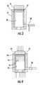
- FIG. 3is an illustration of a pressure vessel having a collimated bundle and polymer matrix loaded and ready for pressing
- FIG. 4is an illustration of a pressure vessel with pressure being applied to the polymer matrix while back pressure is applied to the collimated bundle;
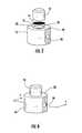
- FIG. 5shows an exploded view of an exemplary pressure vessel
- FIG. 6shows a perspective view of an exemplary pressure vessel
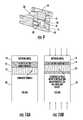
- FIG. 7shows a cross-section view through line 7 - 7 of FIG. 6 ;
- FIG. 8shows a perspective view of an exemplary pressure vessel with a valve to supply and control back pressure attached thereto;
- FIG. 9is a cross-section view through line 9 - 9 of FIG. 8 .
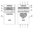
- FIG. 10Ais an illustration of an alternative method of pressing a polymer matrix into a collimated bundle.
- FIG. 10Bis an illustration of an alternative method of pressing a polymer matrix into a collimated bundle, showing the polymer matrix being pressed into the capillaries of the collimated bundle.
- a polymer matrix 14 of a transparent polymer and nanoparticle scintillatorsis placed on top of a collimated bundle 10 having a plurality of capillaries and pressed in a pressure vessel 16 until the polymer matrix 14 is forced into the capillaries. Pressure is applied via an anvil 18 .
- back pressureis supplied to the pressure vessel 16 via a valve 20 , which controls a supply of high pressure gas.
- the back pressuremay also be supplied by a press and support to the collimated bundle is provided by a high melting point thermoplastic. Heat may be applied to the polymer matrix to speed the pressing operation.
- collimated bundles 10are formed from glass from preforms that are drawn, stacked into bundles, and redrawn many times.
- the voids between the drawn glass fibersform the capillaries 12 with a characteristic dimension as small as 3-15 microns.
- the capillarieshave a cross-sectional shape.
- FIG. 2Ashows a collimated bundle 10 having a plurality of hexagonal capillaries 12 .
- FIG. 2Bshows an illustration of a collimated bundle 10 having a plurality of circular capillaries 12 .
- Other profiles or shapes of the capillaries 12may be formed.
- the collimated bundles 10are formed into round disks and may be about 25 mm in diameter, 2 mm thick with an index of refraction of 1.49-1.53, typically of borosilicate glass. Other diameters and thicknesses may be used depending on the desired size of the detector.
- Nanoparticle scintillatorsare embedded into a transparent polymer to create a scintillating material, which will subsequently be force through the capillaries 12 of the collimated bundle 10 .
- the scintillator infused polymerforms a polymer matrix 14 , which will form the ‘cores’ of our scintillating fibers, and the glass of the collimated bundle 10 the ‘cladding’ on the fibers.
- the latterhas a refractive index of 1.49-1.53; the polymer will have a refractive index of at least 1.60 (although since it is doped with the scintillating nanoparticles, the actual refractive index of the cores will be much higher).
- Suitable polymersare preferably thermoplastics and more preferably polystyrene, nylon and polypropylene, other transparent polymers that have a refractive index higher than 1.59 may be suitalbleSuitable nanoparticle scintillator materials are LaBr(3):Ce, LSO:Ce and GdAlO(3):Ce. Other nanoparticle scintillator materials may be used.
- U.S. Publication 2008/0093557 and U.S. Publication 2010/2072234incorporated herein by reference, describe scintillator materials and methods of embedding them in plastics.
- the collimated bundle 10is able to withstand a force required to push the polymer matrix 14 through the capillaries 12 in the collimated bundle disk, which may be made from borosilicate glass, which is able to withstand 63-81 GPa in compression (the lower bound is equivalent to 6.2E4 atmospheres). It is much less strong in tension, and the glass of the collimated bundle will crack under the bending load.
- a polymer infused with nanoparticle scintillators, forming a polymer matrix 14is forced into the capillaries 12 of the collimated bundle 10 .
- sufficient back pressurewill be applied on the exit side of the capillaries 12 so that the unbalanced force on the collimated bundle 10 (i.e. tension) is able to withstand the critical fracture load of bending.
- FIGS. 5-7show an exemplary embodiment of a pressure vessel 16 configured to force the polymer matrix 14 into the capillaries 12 of the collimated bundle 10 .
- the pressure vessel 16is a cylindrical structure having an inner wall 22 forming a chamber inside the pressure vessel 16 .
- the pressure vesselincludes a top surface 24 , which with the inner wall 22 define a first opening into the chamber where the collimated bundle 10 and polymer matrix 14 are loaded for pressing.
- An inner shoulder 26extends inwardly from the inner wall of the pressure chamber forming support for a collimated bundle 10 and polymer matrix 14 stack.
- a surface defining a bore 28 and second opening into chamberis below the inner shoulder 26 and consequently beneath the collimated bundle 10 and polymer matrix 14 stack (when loaded into the pressure vessel 16 ).
- An anvil 18is placed on top of the polymer matrix 14 and collimated bundle 10 for applying pressure to the pressure chamber of the pressure vessel through the first opening.
- pressureis applied to the anvil 18 , via a press, which presses the polymer matrix 14 , forcing it through the capillaries 12 of the collimated bundle 10 .
- heatmay be applied through the anvil 18 and/or the pressure vessel 16 to the polymer matrix 14 to soften the polymer matrix 14 and speed the pressing operation.
- a valveconnected to the bottom opening and is configured to supply and control back pressure to the chamber.
- a high pressure gasis used to supply the back pressure.
- the valvemay be a needle valve.
- the pressure distributionis linear along the capillary length. If we depict the capillaries as comprising a collimated bundle, the pressure distribution is linear throughout and the same across each capillary. In the scheme shown there will be no pressure drop between the collimated bundle and the exit disk because the pressure drop created by the capillaries is much greater than that created by the much larger diameter pressure cell.
- ⁇ ⁇ ⁇ P pressure vessel⁇ ⁇ ⁇ P ⁇ ( 1 - L 1 L total )
- the total flow rate of the polymer through the diskis given by the flow through a single capillary times the number of capillaries, which we calculated here as the ratio of the collimated bundle area to a single capillary area.
- the total flow rateis also equal to the volume of the collimated bundle divided by the time it takes to fill the capillaries in the collimated bundle.
- the exit valveis set at the pressure that the disk experiences, there will be a constant pressure along the whole of the coherent bundle. If the valve were sealed, the pressure vessel would be at the equal to the pressure across the piston. If the valve were open, the stress of the tension would rupture the glass.
- the total resistanceshall be given by the sum of the thickness of the coherent bundle, plus the resistance of the valve in the outflow.
- ⁇ ⁇ ⁇ P 1⁇ ⁇ ⁇ P ⁇ ( 1 - L 1 L 1 + L valve )
- the pressure relief valveis equal to the collimated bundle in the first case sited below: it is equal to the 2 mm thickness. In the second case, however, it is equal to 18 mm.
- the Qrefers to the mass flow in each of the respective cases, i.e. 490.8/t.
- the values for a 25 mm disk with 2 mm thicknessmay be tabulated as:
- FIGS. 10A and 10Ban alternative method of forming the coherent bundle of scintillating fibers is shown where a press is configured to apply pressure to the polymer matrix 14 and back pressure to the collimated bundle 10 simultaneously.
- the collimated bundle 10is supported with a high melting point thermoplastic 30 such as polytetrafluoroethylene (i.e. Teflon).
- the present inventionprovides a unique solution to providing a coherent bundle of scintillating fibers that has markedly increased resolution than prior art x-ray detectors, thereby resulting in higher resolution and more accurate images in medical, engineering and scientific imaging using CT or CAT scanning technologies.
- the coherent bundle of scintillating fibersmay also be used in other fields, such as domestic security and non-destructive testing.
Landscapes
- Engineering & Computer Science (AREA)
- Physics & Mathematics (AREA)
- Mechanical Engineering (AREA)
- General Physics & Mathematics (AREA)
- Life Sciences & Earth Sciences (AREA)
- Health & Medical Sciences (AREA)
- High Energy & Nuclear Physics (AREA)
- Molecular Biology (AREA)
- Spectroscopy & Molecular Physics (AREA)
- Chemical & Material Sciences (AREA)
- Optics & Photonics (AREA)
- Manufacturing & Machinery (AREA)
- General Life Sciences & Earth Sciences (AREA)
- Organic Chemistry (AREA)
- Materials Engineering (AREA)
- Geochemistry & Mineralogy (AREA)
- Ophthalmology & Optometry (AREA)
- Measurement Of Radiation (AREA)
- Casting Or Compression Moulding Of Plastics Or The Like (AREA)
Abstract
Description
Ltotal=L1+Lvalve
tΔP1=1.024×10+9
| atm | Pa | t | A | Q | t | B | Q |
| 1000 | 1.01E8 | 20.2 | 5.05E7 | 24.25 | 10.3 | 9.9E7 | 43.84 |
| 750 | 7.59E7 | 27.01 | 3.78E7 | 18.77 | 14.9 | 6.83E7 | 32.72 |
| 500 | 5.06E7 | 40.47 | 2.79E7 | 12.87 | 22.5 | 4.55E7 | 21.83 |
| 250 | 2.53E7 | 81.26 | 1.26E7 | 6.01 | 45.1 | 2.27E7 | 10.88 |
Claims (12)
Priority Applications (4)
| Application Number | Priority Date | Filing Date | Title |
|---|---|---|---|
| US14/640,069US9611168B2 (en) | 2014-03-06 | 2015-03-06 | Method and apparatus for creating coherent bundle of scintillating fibers |
| US15/449,205US20170176606A1 (en) | 2014-03-06 | 2017-03-03 | Method and apparatus for creating coherent bundle of scintillating fibers |
| US15/626,784US10358376B2 (en) | 2014-03-06 | 2017-06-19 | Method and apparatus for creating coherent bundle of scintillating fibers |
| US16/024,086US10399887B2 (en) | 2014-03-06 | 2018-06-29 | Method and apparatus for creating coherent bundle of scintillating fibers |
Applications Claiming Priority (2)
| Application Number | Priority Date | Filing Date | Title |
|---|---|---|---|
| US201461949192P | 2014-03-06 | 2014-03-06 | |
| US14/640,069US9611168B2 (en) | 2014-03-06 | 2015-03-06 | Method and apparatus for creating coherent bundle of scintillating fibers |
Related Child Applications (1)
| Application Number | Title | Priority Date | Filing Date |
|---|---|---|---|
| US15/449,205ContinuationUS20170176606A1 (en) | 2014-03-06 | 2017-03-03 | Method and apparatus for creating coherent bundle of scintillating fibers |
Publications (2)
| Publication Number | Publication Date |
|---|---|
| US20150253433A1 US20150253433A1 (en) | 2015-09-10 |
| US9611168B2true US9611168B2 (en) | 2017-04-04 |
Family
ID=54017138
Family Applications (2)
| Application Number | Title | Priority Date | Filing Date |
|---|---|---|---|
| US14/640,069ActiveUS9611168B2 (en) | 2014-03-06 | 2015-03-06 | Method and apparatus for creating coherent bundle of scintillating fibers |
| US15/449,205AbandonedUS20170176606A1 (en) | 2014-03-06 | 2017-03-03 | Method and apparatus for creating coherent bundle of scintillating fibers |
Family Applications After (1)
| Application Number | Title | Priority Date | Filing Date |
|---|---|---|---|
| US15/449,205AbandonedUS20170176606A1 (en) | 2014-03-06 | 2017-03-03 | Method and apparatus for creating coherent bundle of scintillating fibers |
Country Status (2)
| Country | Link |
|---|---|
| US (2) | US9611168B2 (en) |
| WO (1) | WO2015134841A1 (en) |
Cited By (2)
| Publication number | Priority date | Publication date | Assignee | Title |
|---|---|---|---|---|
| US20170313938A1 (en)* | 2016-04-27 | 2017-11-02 | Siemens Healthcare Gmbh | Ceramic scintillator fiber |
| US12061357B2 (en) | 2019-07-29 | 2024-08-13 | Luxium Solutions, Llc | Plastic wavelength shifting fiber and a method of making the same |
Families Citing this family (3)
| Publication number | Priority date | Publication date | Assignee | Title |
|---|---|---|---|---|
| JP7114805B2 (en)* | 2018-06-22 | 2022-08-08 | インコム,インコーポレイテッド | Formation of polymer optical devices by template-constrained relaxation expansion |
| US11500228B1 (en) | 2020-03-16 | 2022-11-15 | Apple Inc. | Electronic devices with sheet-packed coherent fiber bundles |
| US20220120921A1 (en)* | 2020-10-16 | 2022-04-21 | Brown Universtiy | High resolution x-ray detector system |
Citations (5)
| Publication number | Priority date | Publication date | Assignee | Title |
|---|---|---|---|---|
| US4022647A (en)* | 1974-12-17 | 1977-05-10 | Personal Communications, Inc. | Method of making coherent optical fiber bundles and face plates |
| US20020072111A1 (en)* | 2000-12-13 | 2002-06-13 | Clarkin James P. | Drawn microchannel array devices and method of analysis using same |
| WO2009008911A2 (en) | 2007-03-05 | 2009-01-15 | Trustees Of Boston University | High definition scintillation detector for medicine, homeland security, and non-destructive evaluation |
| SE531879C2 (en)* | 2008-01-31 | 2009-09-01 | Lei Ye | Scintillation fibers made by electrospinning |
| US20140323946A1 (en)* | 2011-07-08 | 2014-10-30 | Duke University | Phosphors and scintillators for light stimulation within a medium |
Family Cites Families (3)
| Publication number | Priority date | Publication date | Assignee | Title |
|---|---|---|---|---|
| US6271510B1 (en)* | 1998-12-18 | 2001-08-07 | Izzie Boxen | Fiber optic gamma camera having scintillating fibers |
| US7863579B2 (en)* | 2007-05-09 | 2011-01-04 | Avraham Suhami | Directional neutron detector |
| RU119129U1 (en)* | 2012-03-01 | 2012-08-10 | Федеральное государственное автономное образовательное учреждение высшего профессионального образования "Уральский федеральный университет имени первого Президента России Б.Н. Ельцина" | SCINTILLATION DETECTOR |
- 2015
- 2015-03-06USUS14/640,069patent/US9611168B2/enactiveActive
- 2015-03-06WOPCT/US2015/019114patent/WO2015134841A1/enactiveApplication Filing
- 2017
- 2017-03-03USUS15/449,205patent/US20170176606A1/ennot_activeAbandoned
Patent Citations (6)
| Publication number | Priority date | Publication date | Assignee | Title |
|---|---|---|---|---|
| US4022647A (en)* | 1974-12-17 | 1977-05-10 | Personal Communications, Inc. | Method of making coherent optical fiber bundles and face plates |
| US20020072111A1 (en)* | 2000-12-13 | 2002-06-13 | Clarkin James P. | Drawn microchannel array devices and method of analysis using same |
| WO2009008911A2 (en) | 2007-03-05 | 2009-01-15 | Trustees Of Boston University | High definition scintillation detector for medicine, homeland security, and non-destructive evaluation |
| US8477906B2 (en) | 2007-03-05 | 2013-07-02 | Trustees Of Boston University | High definition scintillation detector for medicine, homeland security and non-destructive evaluation |
| SE531879C2 (en)* | 2008-01-31 | 2009-09-01 | Lei Ye | Scintillation fibers made by electrospinning |
| US20140323946A1 (en)* | 2011-07-08 | 2014-10-30 | Duke University | Phosphors and scintillators for light stimulation within a medium |
Non-Patent Citations (2)
| Title |
|---|
| International Search Report, International Application No. PCT/US2015/019114; Jun. 10, 2015, 1page. |
| SCHOTT North America, Inc., "An introduction to Fiber Optic Imaging", Feb. 2007.* |
Cited By (3)
| Publication number | Priority date | Publication date | Assignee | Title |
|---|---|---|---|---|
| US20170313938A1 (en)* | 2016-04-27 | 2017-11-02 | Siemens Healthcare Gmbh | Ceramic scintillator fiber |
| US9938458B2 (en)* | 2016-04-27 | 2018-04-10 | Siemens Healthcare Gmbh | Ceramic scintillator fiber |
| US12061357B2 (en) | 2019-07-29 | 2024-08-13 | Luxium Solutions, Llc | Plastic wavelength shifting fiber and a method of making the same |
Also Published As
| Publication number | Publication date |
|---|---|
| WO2015134841A1 (en) | 2015-09-11 |
| US20170176606A1 (en) | 2017-06-22 |
| US20150253433A1 (en) | 2015-09-10 |
Similar Documents
| Publication | Publication Date | Title |
|---|---|---|
| US20170176606A1 (en) | Method and apparatus for creating coherent bundle of scintillating fibers | |
| US10399887B2 (en) | Method and apparatus for creating coherent bundle of scintillating fibers | |
| US12092774B2 (en) | Method for fabricating pixelated scintillators | |
| CN111289385A (en) | Device and method for detecting mechanical parameters of sediment containing hydrate based on X-CT | |
| US20240033216A1 (en) | Cell housing device | |
| Peterson et al. | Validating hydrodynamic growth in National Ignition Facility implosions | |
| US10358376B2 (en) | Method and apparatus for creating coherent bundle of scintillating fibers | |
| DE102014119694A1 (en) | Flux transport in microfluidic applications | |
| US8344328B2 (en) | Three-dimensional radiation position detector | |
| EP3376507A1 (en) | Ceramic scintillator array, method for manufacturing same, radiation detector and radiation detection device | |
| CN102967611B (en) | Loading sleeve used for industrial CT (computed tomography) experiment table | |
| Amico et al. | Flow through a two-scale porosity, oriented fibre porous medium | |
| WO2011141357A1 (en) | Dispenser and process for releasing flowable materials | |
| Gheller et al. | Microporosity and polymerization contraction as function of depth in dental resin cements by X‐ray computed microtomography | |
| CN115032079A (en) | Compression test device and method for brittle materials with CFRP-magnetorheological elastomer auxiliary loading | |
| Zhou et al. | An apparatus for tensile testing of engineering materials | |
| Manfredi et al. | Packing and permeability properties of E-glass fibre reinforcements functionalised with capsules for self-healing applications | |
| CN210965164U (en) | Detection device and micro-fluidic chip thereof | |
| Jurney et al. | Size-dependent nanoparticle margination and adhesion propensity in a microchannel | |
| Adkins et al. | An examination of metal felt wicks for heat-pipe applications | |
| CN202916217U (en) | Loading sleeve for industrial CT experiment table | |
| DE102019107995B4 (en) | Method for the contactless determination of the shrinkage of resin and use of a device for carrying out the method | |
| Girdwoyń | Nowe metody identyfikacji w praktyce sądowej. | |
| JP2008093332A (en) | X-ray movable diaphragm | |
| JP6670112B2 (en) | Fixing plate for fixing tensile material and method of manufacturing the same |
Legal Events
| Date | Code | Title | Description |
|---|---|---|---|
| AS | Assignment | Owner name:BROWN UNIVERSITY, RHODE ISLAND Free format text:ASSIGNMENT OF ASSIGNORS INTEREST;ASSIGNOR:BULL, CHRISTOPHER;REEL/FRAME:035099/0690 Effective date:20150306 Owner name:BROWN UNIVERSITY, RHODE ISLAND Free format text:ASSIGNMENT OF ASSIGNORS INTEREST;ASSIGNOR:GUPTA, RAJIV;REEL/FRAME:035099/0262 Effective date:20150306 Owner name:BROWN UNIVERSITY, RHODE ISLAND Free format text:ASSIGNMENT OF ASSIGNORS INTEREST;ASSIGNOR:MORSE, THOEDORE F.;REEL/FRAME:035099/0133 Effective date:20150301 | |
| AS | Assignment | Owner name:BROWN UNIVERSITY, RHODE ISLAND Free format text:ASSIGNMENT OF ASSIGNORS INTEREST;ASSIGNOR:WALTZ, PAUL;REEL/FRAME:035111/0555 Effective date:20150306 | |
| AS | Assignment | Owner name:BROWN UNIVERSITY, RHODE ISLAND Free format text:ASSIGNMENT OF ASSIGNORS INTEREST;ASSIGNOR:CRAMER, AVILASH;REEL/FRAME:035295/0573 Effective date:20150321 | |
| STCF | Information on status: patent grant | Free format text:PATENTED CASE | |
| MAFP | Maintenance fee payment | Free format text:PAYMENT OF MAINTENANCE FEE, 4TH YR, SMALL ENTITY (ORIGINAL EVENT CODE: M2551); ENTITY STATUS OF PATENT OWNER: SMALL ENTITY Year of fee payment:4 | |
| FEPP | Fee payment procedure | Free format text:MAINTENANCE FEE REMINDER MAILED (ORIGINAL EVENT CODE: REM.); ENTITY STATUS OF PATENT OWNER: SMALL ENTITY | |
| FEPP | Fee payment procedure | Free format text:7.5 YR SURCHARGE - LATE PMT W/IN 6 MO, SMALL ENTITY (ORIGINAL EVENT CODE: M2555); ENTITY STATUS OF PATENT OWNER: SMALL ENTITY | |
| MAFP | Maintenance fee payment | Free format text:PAYMENT OF MAINTENANCE FEE, 8TH YR, SMALL ENTITY (ORIGINAL EVENT CODE: M2552); ENTITY STATUS OF PATENT OWNER: SMALL ENTITY Year of fee payment:8 |