US9610404B2 - Method for occlusion detection for an infusion pump system - Google Patents
Method for occlusion detection for an infusion pump systemDownload PDFInfo
- Publication number
- US9610404B2 US9610404B2US14/461,678US201414461678AUS9610404B2US 9610404 B2US9610404 B2US 9610404B2US 201414461678 AUS201414461678 AUS 201414461678AUS 9610404 B2US9610404 B2US 9610404B2
- Authority
- US
- United States
- Prior art keywords
- light
- light emitter
- transmissive member
- emitter
- primary
- Prior art date
- Legal status (The legal status is an assumption and is not a legal conclusion. Google has not performed a legal analysis and makes no representation as to the accuracy of the status listed.)
- Active, expires
Links
- 238000001802infusionMethods0.000titleclaimsabstractdescription91
- 238000000034methodMethods0.000titleclaimsdescription43
- 238000001514detection methodMethods0.000titleabstractdescription40
- 239000003814drugSubstances0.000claimsabstractdescription112
- 239000012530fluidSubstances0.000claimsabstractdescription77
- 239000012528membraneSubstances0.000claimsdescription40
- NOESYZHRGYRDHS-UHFFFAOYSA-NinsulinChemical compoundN1C(=O)C(NC(=O)C(CCC(N)=O)NC(=O)C(CCC(O)=O)NC(=O)C(C(C)C)NC(=O)C(NC(=O)CN)C(C)CC)CSSCC(C(NC(CO)C(=O)NC(CC(C)C)C(=O)NC(CC=2C=CC(O)=CC=2)C(=O)NC(CCC(N)=O)C(=O)NC(CC(C)C)C(=O)NC(CCC(O)=O)C(=O)NC(CC(N)=O)C(=O)NC(CC=2C=CC(O)=CC=2)C(=O)NC(CSSCC(NC(=O)C(C(C)C)NC(=O)C(CC(C)C)NC(=O)C(CC=2C=CC(O)=CC=2)NC(=O)C(CC(C)C)NC(=O)C(C)NC(=O)C(CCC(O)=O)NC(=O)C(C(C)C)NC(=O)C(CC(C)C)NC(=O)C(CC=2NC=NC=2)NC(=O)C(CO)NC(=O)CNC2=O)C(=O)NCC(=O)NC(CCC(O)=O)C(=O)NC(CCCNC(N)=N)C(=O)NCC(=O)NC(CC=3C=CC=CC=3)C(=O)NC(CC=3C=CC=CC=3)C(=O)NC(CC=3C=CC(O)=CC=3)C(=O)NC(C(C)O)C(=O)N3C(CCC3)C(=O)NC(CCCCN)C(=O)NC(C)C(O)=O)C(=O)NC(CC(N)=O)C(O)=O)=O)NC(=O)C(C(C)CC)NC(=O)C(CO)NC(=O)C(C(C)O)NC(=O)C1CSSCC2NC(=O)C(CC(C)C)NC(=O)C(NC(=O)C(CCC(N)=O)NC(=O)C(CC(N)=O)NC(=O)C(NC(=O)C(N)CC=1C=CC=CC=1)C(C)C)CC1=CN=CN1NOESYZHRGYRDHS-UHFFFAOYSA-N0.000claimsdescription36
- 102000004877InsulinHuman genes0.000claimsdescription18
- 108090001061InsulinProteins0.000claimsdescription18
- 229940125396insulinDrugs0.000claimsdescription18
- 238000004891communicationMethods0.000claimsdescription15
- 230000003213activating effectEffects0.000claimsdescription11
- 230000004044responseEffects0.000claimsdescription11
- 230000004913activationEffects0.000claimsdescription3
- 238000002955isolationMethods0.000claimsdescription3
- 230000007613environmental effectEffects0.000abstractdescription10
- 230000008569processEffects0.000description24
- 239000000853adhesiveSubstances0.000description6
- 230000001070adhesive effectEffects0.000description6
- 210000005166vasculatureAnatomy0.000description6
- 230000005540biological transmissionEffects0.000description5
- 230000008859changeEffects0.000description5
- 230000000295complement effectEffects0.000description5
- 238000011282treatmentMethods0.000description5
- XLYOFNOQVPJJNP-UHFFFAOYSA-NwaterSubstancesOXLYOFNOQVPJJNP-UHFFFAOYSA-N0.000description5
- 230000037452primingEffects0.000description4
- 238000010276constructionMethods0.000description3
- 229940079593drugDrugs0.000description3
- 238000013508migrationMethods0.000description3
- 230000005012migrationEffects0.000description3
- 238000012544monitoring processMethods0.000description3
- 239000002861polymer materialSubstances0.000description3
- 230000009467reductionEffects0.000description3
- 239000000758substrateSubstances0.000description3
- 206010012601diabetes mellitusDiseases0.000description2
- 230000033001locomotionEffects0.000description2
- 238000004519manufacturing processMethods0.000description2
- 239000000463materialSubstances0.000description2
- 238000005259measurementMethods0.000description2
- 238000012545processingMethods0.000description2
- 230000000717retained effectEffects0.000description2
- 230000002441reversible effectEffects0.000description2
- 238000012552reviewMethods0.000description2
- 238000007920subcutaneous administrationMethods0.000description2
- 239000012780transparent materialSubstances0.000description2
- 238000012935AveragingMethods0.000description1
- HTQBXNHDCUEHJF-XWLPCZSASA-NExenatideChemical compoundC([C@@H](C(=O)N[C@@H]([C@@H](C)CC)C(=O)N[C@@H](CCC(O)=O)C(=O)N[C@@H](CC=1C2=CC=CC=C2NC=1)C(=O)N[C@@H](CC(C)C)C(=O)N[C@@H](CCCCN)C(=O)N[C@@H](CC(N)=O)C(=O)NCC(=O)NCC(=O)N1[C@@H](CCC1)C(=O)N[C@@H](CO)C(=O)N[C@@H](CO)C(=O)NCC(=O)N[C@@H](C)C(=O)N1[C@@H](CCC1)C(=O)N1[C@@H](CCC1)C(=O)N1[C@@H](CCC1)C(=O)N[C@@H](CO)C(N)=O)NC(=O)[C@H](CC(C)C)NC(=O)[C@H](CCCNC(N)=N)NC(=O)[C@@H](NC(=O)[C@H](C)NC(=O)[C@H](CCC(O)=O)NC(=O)[C@H](CCC(O)=O)NC(=O)[C@H](CCC(O)=O)NC(=O)[C@H](CCSC)NC(=O)[C@H](CCC(N)=O)NC(=O)[C@H](CCCCN)NC(=O)[C@H](CO)NC(=O)[C@H](CC(C)C)NC(=O)[C@H](CC(O)=O)NC(=O)[C@H](CO)NC(=O)[C@@H](NC(=O)[C@H](CC=1C=CC=CC=1)NC(=O)[C@@H](NC(=O)CNC(=O)[C@H](CCC(O)=O)NC(=O)CNC(=O)[C@@H](N)CC=1NC=NC=1)[C@@H](C)O)[C@@H](C)O)C(C)C)C1=CC=CC=C1HTQBXNHDCUEHJF-XWLPCZSASA-N0.000description1
- 108010011459ExenatideProteins0.000description1
- 208000006440Open BiteDiseases0.000description1
- 208000001132OsteoporosisDiseases0.000description1
- 239000002313adhesive filmSubstances0.000description1
- XAGFODPZIPBFFR-UHFFFAOYSA-NaluminiumChemical compound[Al]XAGFODPZIPBFFR-UHFFFAOYSA-N0.000description1
- 229910052782aluminiumInorganic materials0.000description1
- 230000003474anti-emetic effectEffects0.000description1
- 239000002111antiemetic agentSubstances0.000description1
- 229940125683antiemetic agentDrugs0.000description1
- 230000009286beneficial effectEffects0.000description1
- 230000036772blood pressureEffects0.000description1
- 229940084891byettaDrugs0.000description1
- 150000001875compoundsChemical class0.000description1
- 230000000694effectsEffects0.000description1
- 229920005570flexible polymerPolymers0.000description1
- 239000008103glucoseSubstances0.000description1
- 239000003292glueSubstances0.000description1
- 238000001794hormone therapyMethods0.000description1
- 229940124508injectable medicineDrugs0.000description1
- 230000002452interceptive effectEffects0.000description1
- 230000007257malfunctionEffects0.000description1
- 238000012986modificationMethods0.000description1
- 230000004048modificationEffects0.000description1
- 230000003287optical effectEffects0.000description1
- 230000035515penetrationEffects0.000description1
- 108010029667pramlintideProteins0.000description1
- NRKVKVQDUCJPIZ-MKAGXXMWSA-Npramlintide acetateChemical compoundC([C@@H](C(=O)NCC(=O)N1CCC[C@H]1C(=O)N[C@@H]([C@@H](C)CC)C(=O)N[C@@H](CC(C)C)C(=O)N1[C@@H](CCC1)C(=O)N1[C@@H](CCC1)C(=O)N[C@@H]([C@@H](C)O)C(=O)N[C@@H](CC(N)=O)C(=O)N[C@@H](C(C)C)C(=O)NCC(=O)N[C@@H](CO)C(=O)N[C@@H](CC(N)=O)C(=O)N[C@@H]([C@@H](C)O)C(=O)N[C@@H](CC=1C=CC(O)=CC=1)C(N)=O)NC(=O)[C@H](CC(N)=O)NC(=O)[C@H](CC(N)=O)NC(=O)[C@H](CO)NC(=O)[C@H](CO)NC(=O)[C@H](CC=1NC=NC=1)NC(=O)[C@@H](NC(=O)[C@H](CC(C)C)NC(=O)[C@H](CC=1C=CC=CC=1)NC(=O)[C@H](CC(N)=O)NC(=O)[C@H](C)NC(=O)[C@H](CC(C)C)NC(=O)[C@H](CCCNC(N)=N)NC(=O)[C@H](CCC(N)=O)NC(=O)[C@@H](NC(=O)[C@H](C)NC(=O)[C@H](CS)NC(=O)[C@@H](NC(=O)[C@H](C)NC(=O)[C@@H](NC(=O)[C@H](CC(N)=O)NC(=O)[C@H](CS)NC(=O)[C@@H](N)CCCCN)[C@@H](C)O)[C@@H](C)O)[C@@H](C)O)C(C)C)C1=CC=CC=C1NRKVKVQDUCJPIZ-MKAGXXMWSA-N0.000description1
- 238000003825pressingMethods0.000description1
- 229910052710siliconInorganic materials0.000description1
- 239000010703siliconSubstances0.000description1
- 239000013589supplementSubstances0.000description1
- 229940099093symlinDrugs0.000description1
- 238000012546transferMethods0.000description1
- 238000011144upstream manufacturingMethods0.000description1
- 230000000007visual effectEffects0.000description1
Images


Classifications
- A—HUMAN NECESSITIES
- A61—MEDICAL OR VETERINARY SCIENCE; HYGIENE
- A61M—DEVICES FOR INTRODUCING MEDIA INTO, OR ONTO, THE BODY; DEVICES FOR TRANSDUCING BODY MEDIA OR FOR TAKING MEDIA FROM THE BODY; DEVICES FOR PRODUCING OR ENDING SLEEP OR STUPOR
- A61M5/00—Devices for bringing media into the body in a subcutaneous, intra-vascular or intramuscular way; Accessories therefor, e.g. filling or cleaning devices, arm-rests
- A61M5/14—Infusion devices, e.g. infusing by gravity; Blood infusion; Accessories therefor
- A61M5/168—Means for controlling media flow to the body or for metering media to the body, e.g. drip meters, counters ; Monitoring media flow to the body
- A61M5/16831—Monitoring, detecting, signalling or eliminating infusion flow anomalies
- A—HUMAN NECESSITIES
- A61—MEDICAL OR VETERINARY SCIENCE; HYGIENE
- A61M—DEVICES FOR INTRODUCING MEDIA INTO, OR ONTO, THE BODY; DEVICES FOR TRANSDUCING BODY MEDIA OR FOR TAKING MEDIA FROM THE BODY; DEVICES FOR PRODUCING OR ENDING SLEEP OR STUPOR
- A61M5/00—Devices for bringing media into the body in a subcutaneous, intra-vascular or intramuscular way; Accessories therefor, e.g. filling or cleaning devices, arm-rests
- A61M5/14—Infusion devices, e.g. infusing by gravity; Blood infusion; Accessories therefor
- A61M5/1413—Modular systems comprising interconnecting elements
- A—HUMAN NECESSITIES
- A61—MEDICAL OR VETERINARY SCIENCE; HYGIENE
- A61M—DEVICES FOR INTRODUCING MEDIA INTO, OR ONTO, THE BODY; DEVICES FOR TRANSDUCING BODY MEDIA OR FOR TAKING MEDIA FROM THE BODY; DEVICES FOR PRODUCING OR ENDING SLEEP OR STUPOR
- A61M39/00—Tubes, tube connectors, tube couplings, valves, access sites or the like, specially adapted for medical use
- A61M39/22—Valves or arrangement of valves
- A61M39/28—Clamping means for squeezing flexible tubes, e.g. roller clamps
- A61M39/284—Lever clamps
- A—HUMAN NECESSITIES
- A61—MEDICAL OR VETERINARY SCIENCE; HYGIENE
- A61M—DEVICES FOR INTRODUCING MEDIA INTO, OR ONTO, THE BODY; DEVICES FOR TRANSDUCING BODY MEDIA OR FOR TAKING MEDIA FROM THE BODY; DEVICES FOR PRODUCING OR ENDING SLEEP OR STUPOR
- A61M5/00—Devices for bringing media into the body in a subcutaneous, intra-vascular or intramuscular way; Accessories therefor, e.g. filling or cleaning devices, arm-rests
- A61M5/14—Infusion devices, e.g. infusing by gravity; Blood infusion; Accessories therefor
- A61M5/142—Pressure infusion, e.g. using pumps
- A61M5/14244—Pressure infusion, e.g. using pumps adapted to be carried by the patient, e.g. portable on the body
- A61M5/14248—Pressure infusion, e.g. using pumps adapted to be carried by the patient, e.g. portable on the body of the skin patch type
- A—HUMAN NECESSITIES
- A61—MEDICAL OR VETERINARY SCIENCE; HYGIENE
- A61M—DEVICES FOR INTRODUCING MEDIA INTO, OR ONTO, THE BODY; DEVICES FOR TRANSDUCING BODY MEDIA OR FOR TAKING MEDIA FROM THE BODY; DEVICES FOR PRODUCING OR ENDING SLEEP OR STUPOR
- A61M5/00—Devices for bringing media into the body in a subcutaneous, intra-vascular or intramuscular way; Accessories therefor, e.g. filling or cleaning devices, arm-rests
- A61M5/14—Infusion devices, e.g. infusing by gravity; Blood infusion; Accessories therefor
- A61M5/142—Pressure infusion, e.g. using pumps
- A61M5/145—Pressure infusion, e.g. using pumps using pressurised reservoirs, e.g. pressurised by means of pistons
- A61M5/1452—Pressure infusion, e.g. using pumps using pressurised reservoirs, e.g. pressurised by means of pistons pressurised by means of pistons
- A61M5/14566—Pressure infusion, e.g. using pumps using pressurised reservoirs, e.g. pressurised by means of pistons pressurised by means of pistons with a replaceable reservoir for receiving a piston rod of the pump
- A—HUMAN NECESSITIES
- A61—MEDICAL OR VETERINARY SCIENCE; HYGIENE
- A61M—DEVICES FOR INTRODUCING MEDIA INTO, OR ONTO, THE BODY; DEVICES FOR TRANSDUCING BODY MEDIA OR FOR TAKING MEDIA FROM THE BODY; DEVICES FOR PRODUCING OR ENDING SLEEP OR STUPOR
- A61M5/00—Devices for bringing media into the body in a subcutaneous, intra-vascular or intramuscular way; Accessories therefor, e.g. filling or cleaning devices, arm-rests
- A61M5/14—Infusion devices, e.g. infusing by gravity; Blood infusion; Accessories therefor
- A61M5/168—Means for controlling media flow to the body or for metering media to the body, e.g. drip meters, counters ; Monitoring media flow to the body
- A61M5/16831—Monitoring, detecting, signalling or eliminating infusion flow anomalies
- A61M5/16854—Monitoring, detecting, signalling or eliminating infusion flow anomalies by monitoring line pressure
- A—HUMAN NECESSITIES
- A61—MEDICAL OR VETERINARY SCIENCE; HYGIENE
- A61M—DEVICES FOR INTRODUCING MEDIA INTO, OR ONTO, THE BODY; DEVICES FOR TRANSDUCING BODY MEDIA OR FOR TAKING MEDIA FROM THE BODY; DEVICES FOR PRODUCING OR ENDING SLEEP OR STUPOR
- A61M5/00—Devices for bringing media into the body in a subcutaneous, intra-vascular or intramuscular way; Accessories therefor, e.g. filling or cleaning devices, arm-rests
- A61M5/14—Infusion devices, e.g. infusing by gravity; Blood infusion; Accessories therefor
- A61M5/142—Pressure infusion, e.g. using pumps
- A61M5/14244—Pressure infusion, e.g. using pumps adapted to be carried by the patient, e.g. portable on the body
- A61M2005/14268—Pressure infusion, e.g. using pumps adapted to be carried by the patient, e.g. portable on the body with a reusable and a disposable component
- A—HUMAN NECESSITIES
- A61—MEDICAL OR VETERINARY SCIENCE; HYGIENE
- A61M—DEVICES FOR INTRODUCING MEDIA INTO, OR ONTO, THE BODY; DEVICES FOR TRANSDUCING BODY MEDIA OR FOR TAKING MEDIA FROM THE BODY; DEVICES FOR PRODUCING OR ENDING SLEEP OR STUPOR
- A61M5/00—Devices for bringing media into the body in a subcutaneous, intra-vascular or intramuscular way; Accessories therefor, e.g. filling or cleaning devices, arm-rests
- A61M5/14—Infusion devices, e.g. infusing by gravity; Blood infusion; Accessories therefor
- A61M5/168—Means for controlling media flow to the body or for metering media to the body, e.g. drip meters, counters ; Monitoring media flow to the body
- A61M5/16831—Monitoring, detecting, signalling or eliminating infusion flow anomalies
- A61M2005/16863—Occlusion detection
- A—HUMAN NECESSITIES
- A61—MEDICAL OR VETERINARY SCIENCE; HYGIENE
- A61M—DEVICES FOR INTRODUCING MEDIA INTO, OR ONTO, THE BODY; DEVICES FOR TRANSDUCING BODY MEDIA OR FOR TAKING MEDIA FROM THE BODY; DEVICES FOR PRODUCING OR ENDING SLEEP OR STUPOR
- A61M2205/00—General characteristics of the apparatus
- A61M2205/33—Controlling, regulating or measuring
- A61M2205/3306—Optical measuring means
Definitions
- This documentrelates to an infusion pump system, such as a portable infusion pump system for dispensing insulin or another medication.
- a medical infusion pump devicemay be used to deliver a medicine to a patient as part of a medical treatment.
- the medicine that is delivered by the infusion pump devicecan depend on the condition of the patient and the desired treatment plan.
- infusion pump deviceshave been used to deliver insulin to the vasculature of diabetes patients so as to regulate blood-glucose levels.
- Some traditional infusion pump devicesmay include an occlusion detection system for purposes of determining when the medicine dispensation is inadvertently interrupted or interfered. If the medicine dispensation path to the user is occluded, the user may receive no dosage or a lower dosage of the medicine.
- Some occlusion detections systems for infusion pumpscan be configured as a “dry side” detector in which a sensor is positioned along a component of the drive system to detect a malfunction or change in pressure.
- Other occlusion detection systems for infusion pumpscan be configured as a “wet side” detector in which characteristics of the fluid flow path are monitored. In some circumstances, the occlusion detection systems may be sensitive to environmental conditions (e.g., ambient temperature, pressure, or the like) in a manner that could cause false indications of a flow path occlusion.
- an infusion pump systeminclude an occlusion detection system to detect when an occlusion exists in the fluid path between the medicine reservoir and the infusion site located, for example, on the user's skin. Such an occlusion may occur, for example, when the fluid flow line (e.g., a cannula, infusion set tubing, or the like) is kinked.
- the occlusion detection systemcan be configured to account for changes in environmental conditions, such as ambient temperature, pressure, or the like, so that the occlusion detection system provides reliable feedback to a user as to the occluded or non-occluded state of the medicine flow path.
- the occlusion sensorcan be used to indicate when the fluid is flowing or not flowing, thereby permitting the infusion pump system to communicate an alarm to the user if an occlusion exists.
- the occlusion sensor systemmay include a fluid channel that at least partially defines an insulin flow path between an insulin reservoir and an output port.
- the systemmay also include a flexible membrane in fluid communication with the fluid channel so that fluid pressure in the fluid channel acts upon the flexible membrane.
- the systemmay further include an air cavity positioned adjacent to the flexible membrane and generally opposite the fluid channel.
- the systemmay include a light transmissive member adjacent to the air cavity. The light transmissive member may be arranged opposite the flexible membrane such that fluid pressure in the fluid channel above a threshold value causes the flexible membrane to deform into the air cavity and toward the light transmissive member.
- the systemmay also include a primary light emitter configured to align with the light transmissive member and emit light into the light transmissive member.
- the systemmay further include a light sensor configured to align with the light transmissive member and receive light from the primary light emitter that passes through the light transmissive member.
- the systemmay include a reference light emitter configured to emit light that is received by the light sensor, wherein the reference light emitter is spaced apart from the primary light emitter.
- Some embodiment described hereinmay include occlusion sensor system for an infusion pump system including a reusable controller device that is removably attachable to a disposable single-use pump device that defines a space to receive medicine therein.
- the occlusion sensor systemmay include a primary light emitter, a reference light emitter, and a light sensor arranged in the reusable controller device.
- the primary light emitter, the reference light emitter, and the light sensormay be in electrical communication with control circuitry housed inside the reusable controller device.
- the systemmay also include a light transmissive member arranged in the disposable single-use pump device. The light transmissive member may be aligned with the primary light emitter and the light sensor when the reusable controller device is removably attached to a disposable single-use pump device.
- the light sensormay be positioned relative to the light transmissive member so as to receive light from the primary light emitter that passes through the light transmissive member in response to activation of the primary light emitter. Also, in response to activation of the reference light emitter, the light sensor may receive light emitted from the reference light emitter without passing through the light transmissive member.
- the occlusion sensor systemmay include a primary light emitter configured to emit light toward an insulin flow path.
- the systemmay also include a light sensor configured to receive at least a portion of the light from the primary light emitter after the light is emitted toward the insulin flow path.
- the light sensormay output an electrical signal in response to receiving light.
- the systemmay further include a reference light emitter configured to emit light that is received by the light sensor.
- the reference light emittermay be separate from the primary light emitter.
- the systemmay further include control circuitry electrically connected to the primary light emitter, the reference light emitter, and the light sensor.
- the control circuitrymay compare a first value indicative of light detected at the light sensor from the primary light emitter to a second value indicative of light detected at the light sensor from the reference light emitter. In response to the comparison of the first value to the second value being outside of a threshold range, the control circuitry may generate an occlusion alarm for output via a user interface.
- Some embodimentsinclude a method for detecting an occlusion in a flow path from an infusion pump system.
- the methodmay include activating a reference light emitter to direct light toward a light sensor housed in an infusion pump system.
- the light sensormay generate an electrical signal in response to receiving light from the reference light emitter.
- the methodmay also include determining a first value indicative of light detected at the light sensor from the reference light emitter.
- the methodmay further include activating a primary light emitter to direct toward a medicine flow path for the infusion pump system.
- the light sensormay receive a least a portion of the light emitted from the primary light emitter.
- the methodmay include determining a second value indicative of light detected at the light sensor from the primary light emitter.
- the methodmay also include determining if an occlusion exists in the medicine flow path based at least in part on a comparison of the second value to the first value.
- the infusion pump systemmay include an occlusion detection system configured to reliably detects occlusions in the medicine flow path even when the infusion pump system is exposed to significant changes in environments conditions.
- the occlusion detection systemcan be configured to self-calibrate and thereby account for changes in ambient temperature so that the occlusion detection system provides reliable feedback even when the infusion pump system is carried in low-temperature conditions.
- the occlusion detection systemcan provide notice to the user if he or she is receiving no dosage or a lower dosage of the medicine due to an occlusion in the medicine flow path.
- the occlusion detection systemmay employ at least two different light emitters for each light sensor.
- the occlusion detection systemmay include a primary light emitter that emits a light for communication toward the medicine flow path and is received at a light detector (e.g., after internal reflection of the light).
- the occlusion detection systemmay include a reference light emitter that emits a light for communication along a different path toward the light detector. As such, a comparison of the detected light signal from the reference light emitter and the detected light signal from the primary light emitter can be employed to calibrate the occlusion detection system to account for changes in environmental conditions.
- some embodiments of the infusion pump systemmay include a reusable controller device that houses the electronic components of the occlusion detection system even though the electronic components of the occlusion sensor system are used to detect characteristics the medicine flow path passing through a removable pump device.
- sensor signals of the occlusion detection systemcan be readily communicated to control circuitry of the reusable controller device to determine if an occlusion exists. If so, the user interface of the controller device can be used to promptly alert the user of the problem.
- some embodiments of the infusion pump systemmay be configured to be portable, wearable, and (in some circumstances) concealable.
- a usercan conveniently wear the infusion pump system on the user's skin under clothing or can carry the pump device in the user's pocket (or other portable location) while receiving the medicine dispensed from the pump device.
- FIG. 1is an exploded perspective view of an infusion pump system in accordance with some embodiments.
- FIG. 2is a perspective view of the infusion pump system of FIG. 1 in a detached state.
- FIG. 3is a perspective view of an infusion pump system, in accordance with some embodiments.
- FIGS. 4-5are perspective views of the pump device of FIGS. 1-2 being discarded and the controller device of FIGS. 1-2 being reused with a new pump device.
- FIG. 6is an exploded perspective view of a controller device for an infusion pump system, in accordance with some embodiments.
- FIG. 7is an exploded perspective view of a pump device for an infusion pump system, in accordance with some embodiments.
- FIG. 8is a cross-section view of the cap device and the medicine cartridge of FIG. 1 .
- FIG. 9is a perspective view of an alignment of the cap device and occlusion detection system, in accordance with some embodiments.
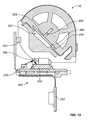
- FIG. 10is a cross-sectional perspective view of the alignment shown in FIG. 9 .
- FIG. 11is an exploded view of the cap device, in accordance with some embodiments.
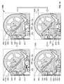
- FIGS. 12-14are cross-sectional views of the cap device and occlusion detection system, in accordance with some embodiments.
- FIGS. 15-16are a flow charts used to detect whether the infusion pump system is in an occluded or non-occluded state, in accordance with some embodiments.
- an infusion pump system 10can include a pump device 100 and a controller device 200 that communicates with the pump device 100 .
- the pump device 100in this embodiment includes a housing structure 110 that defines a cavity 116 in which a fluid cartridge 120 can be received.
- the pump device 100also can include a cap device 130 to retain the fluid cartridge 120 in the cavity 116 of the housing structure 110 .
- the pump device 100can include a drive system that advances a plunger 125 in the fluid cartridge 120 so as to dispense fluid therefrom. As described in more detail below in connection with FIGS.
- the pump systemcan include an occlusion detection system 250 that is advantageously configured to self-calibrate in a manner that accounts for changes in environmental conditions, such as ambient temperature, pressure, or the like.
- the occlusion detection system 250may provide reliable feedback to a user as to the occluded or non-occluded state of the medicine flow path extending between the fluid cartridge 120 and the infusion site.
- the controller device 200communicates with the pump device 100 to control the operation of the drive system.
- the controller device 200 , the pump device 100 (including the cap device 130 ), and the fluid cartridge 120are assembled together, the user can (in some embodiments) conveniently wear the infusion pump system 10 on the user's skin under clothing, in a pouch clipped at the waist (e.g., similar to a cell phone pouch), or in the user's pocket while receiving the fluid dispensed from the pump device 100 .
- the controller device 200may be configured as a reusable component that provides electronics and a user interface to control the operation of the pump device 100 .
- the pump device 100can be a disposable component that is disposed of after a single use.
- the pump device 100can be a “one time use” component that is thrown away after the fluid cartridge 120 therein is exhausted. Thereafter, the user can removably attach a new pump device 100 ′ (having a new medicine cartridge 120 ′) to the reusable controller device 200 for the dispensation of fluid from a new fluid cartridge 120 ′. Accordingly, the user is permitted to reuse the controller device 200 (which may include complex or valuable electronics, as well as a rechargeable battery) while disposing of the relatively low-cost pump device 100 after each use.
- a pump system 10can provide enhanced user safety as a new pump device 100 ′ (and drive system therein) is employed with each new fluid cartridge 120 ′.
- the pump device 100is configured to removably attach to the controller device 200 in a manner that provides a secure fitting, an overall compact size, and a reliable electrical connection that is resistant to water migration.
- the controller device 200can include a housing 210 having a number of features that mate with complementary features of the pump housing 110 .
- the controller device 200can removably attach with the pump device 100 in a generally side-by-side configuration.
- the compact sizepermits the infusion pump system 10 to be discrete and portable (as described below in connection with FIG. 3 ).
- the pump system 10can be a medical infusion pump system that is configured to controllably dispense a medicine from the cartridge 120 .
- the fluid cartridge 120can contain a medicine 126 to be infused into the tissue or vasculature of a targeted individual, such as a human or animal patient.
- the pump device 100can be adapted to receive a medicine cartridge 120 in the form of a carpule that is preloaded with insulin or another medicine for use in the treatment of Diabetes (e.g., Byetta®, Symlin®, or others).
- a medicine cartridge 120may be supplied, for example, by Eli Lilly and Co. of Indianapolis, Ind.
- the fluid cartridge 120may have other configurations.
- the fluid cartridge 120may comprise a reservoir that is integral with the pump housing structure 110 (e.g., the fluid cartridge 120 can be defined by one or more walls of the pump housing structure 110 that surround a plunger to define a reservoir in which the medicine is injected or otherwise received).
- the pump device 100can include one or more structures that interfere with the removal of the medicine cartridge 120 after the medicine cartridge 120 is inserted into the cavity 116 .
- the pump housing structure 110can include one or more retainer wings (not shown in FIG. 1 ) that at least partially extend into the cavity 116 to engage a portion of the medicine cartridge 120 when the medicine cartridge 120 is installed therein. Such a configuration may facilitate the “one-time-use” feature of the pump device 100 .
- the retainer wingscan interfere with attempts to remove the medicine cartridge 120 from the pump device 100 , thus ensuring that the pump device 100 will be discarded along with the medicine cartridge 120 after the medicine cartridge 120 is emptied, expired, or otherwise exhausted.
- the pump device 100can operate in a tamper-resistant and safe manner because the pump device 100 can be designed with a predetermined life expectancy (e.g., the “one-time-use” feature in which the pump device is discarded after the medicine cartridge 120 is emptied, expired, or otherwise exhausted).
- a predetermined life expectancye.g., the “one-time-use” feature in which the pump device is discarded after the medicine cartridge 120 is emptied, expired, or otherwise exhausted.
- the controller device 200can be removably attached to the pump device 100 so that the two components are mechanically mounted to one another in a fixed relationship. Such a mechanical mounting can form an electrical connection between the removable controller device 200 and the pump device 100 .
- the controller device 200can be in electrical communication with a portion of a drive system (not shown in FIG. 1 ) of the pump device 100 .
- the pump device 100can include a drive system that causes controlled dispensation of the medicine or other fluid from the cartridge 120 .
- the drive systemincrementally advances a piston rod (not shown in FIG. 1 ) longitudinally into the cartridge 120 so that the fluid is forced out of an output end 122 .
- a septum 121FIG.
- the cap device 130may include a penetration needle that punctures the septum 121 during attachment of the cap device to the housing structure 110 .
- the controller device 200communicates electronic control signals via a hardwire-connection (e.g., electrical contacts or the like) to the drive system or other components of the pump device 100 .
- the drive system of the pump device 100causes medicine to incrementally dispense from the medicine cartridge 120 .
- Power signalssuch as signals from the rechargeable battery 245 (refer to FIG. 6 ) of the controller device 200 and from the power source 310 (refer to FIG. 7 ) of the pump device 100 may also be passed between the controller device 200 and the pump device 100 .
- the pump device 100can include an electrical connector 118 (e.g., having conductive pads, pins, and the like) that is exposed to the controller device 200 and that mates with a complementary electrical connector (refer to connector 218 in FIG. 2 ) on the adjacent face of the controller device 200 .
- the electrical connectors 118 and 218provide the electrical communication between the control circuitry (refer, for example, to FIG. 6 ) housed in the controller device 200 and at least a portion of the drive system or other components of the pump device 100 .
- the electrical connectors 118 and 218can permit the transmission of electrical control signals to the pump device 100 and the reception of feedback signals (e.g., sensor signals) from particular components within the pump device 100 .
- the electrical connectors 118 and 218may similarly facilitate transmission of one or more power signals from the rechargeable battery pack 245 to the pump device 100 , where the signals may be used to provide power to components of the pump device 100 , or to transmit one or more power signals from the power source 310 to the controller device, where the signals may be used to charge the rechargeable battery 245 or to power components of the controller device 200 .
- the controller device 200can include a user interface 220 that permits a user to monitor the operation of the pump device 100 .
- the user interface 220can include a display device 222 and one or more user-selectable buttons (e.g., several buttons 224 are shown in the embodiment of FIG. 1 ).
- the display device 222can include an active area in which numerals, text, symbols, images, or a combination thereof can be displayed.
- the display device 222can be used to communicate a number of settings or menu options for the infusion pump system 10 .
- the usermay press one or more of the buttons to shuffle through a number of menus or program screens that show particular settings and data (e.g., review data that shows the medicine dispensing rate, the total amount of medicine dispensed in a given time period, the amount of medicine scheduled to be dispensed at a particular time or date, the approximate amount of medicine remaining in the cartridge 120 , or the like).
- the usercan adjust the settings or otherwise program the controller device 200 by pressing one or more buttons of the user interface 220 .
- the usermay press one or more of the buttons to change the dispensation rate of insulin or to request that a bolus of insulin be dispensed immediately or at a scheduled, later time.
- the display device 222may also be used to communicate information regarding remaining battery life.
- the userwhen the controller device 200 is connected to the pump device 100 , the user can be provided with the opportunity to readily monitor the infusion pump operation by simply viewing the user interface 220 of the controller device 200 connected to the pump device 100 .
- Such monitoring capabilitiesmay provide comfort to a user who may have urgent questions about the current operation of the pump device 100 .
- there may be no need for the user to carry and operate a separate module to monitor the operation of the pump device 100thereby simplifying the monitoring process and reducing the number of devices that must be carried by the user.
- the usercan readily operate the user interface 220 of the controller device 200 , which is removably attached to the pump device 100 , without the requirement of locating and operating a separate monitoring module.
- the controller device 200can be removably attached to the pump device 100 in a side-by-side arrangement.
- the pump device 100may be moved in a longitudinal direction (e.g., refer to direction 219 in FIG. 4 ) toward the controller device 200 until the complementary features connect and secure the separate components in the side-by-side arrangement.
- the controller device 200can include a controller housing structure 210 having a number of features that are configured to mate with complementary features of the pump housing structure 110 so as to form a releasable mechanical connection.
- the pump housing structure 110can include a barrel 111 that mates with a complementary barrel channel 211 of the controller housing 210 .
- the pump device 100 and the controller device 200can be mounted to one another so that the assembled system 10 is resistant to water migration both into the pump housing structure 110 and the controller housing structure 210 .
- Such a configurationcan also provide water-resistant protection for the electrical connection between the pump device 100 and the controller device 200 .
- the sensitive internal components in the controller device 200 and the pump device 100can be reliably protected from water migration if the user encounters water (e.g., rain, incidental splashing, and the like) while using the pump system 10 .
- the infusion pump system 10can be configured to be portable and can be wearable and concealable.
- a usercan conveniently wear the infusion pump system 10 on the user's skin (e.g., skin adhesive) underneath the user's clothing or carry the pump device 100 in the user's pocket (or other portable location) while receiving the medicine dispensed from the pump device 100 .
- the pump system 10is shown in FIG. 3 as being held in a user's hand 5 so as to illustrate an exemplary size of the system 10 in accordance with some embodiments.
- This embodiment of the infusion pump system 10is compact so that the user can wear the portable infusion pump system 10 (e.g., in the user's pocket, connected to a belt clip, adhered to the user's skin, or the like) without the need for carrying and operating a separate module.
- the cap device 130 of the pump device 100can be configured to mate with an infusion set 146 .
- the infusion set 146can be a tubing system that connects the infusion pump system 10 to the tissue or vasculature of the user (e.g., to deliver medicine into the tissue or vasculature under the user's skin)
- the infusion set 146can include a flexible tube 147 that extends from the pump device 100 to a subcutaneous cannula 149 that may be retained by a skin adhesive patch (not shown) that secures the subcutaneous cannula 149 to the infusion site.
- the skin adhesive patchcan retain the infusion cannula 149 in fluid communication with the tissue or vasculature of the patient so that the medicine dispensed through the tube 147 passes through the cannula 149 and into the user's body.
- the cap device 130can provide fluid communication between the output end 122 ( FIG. 1 ) of the medicine cartridge 120 and the tube 147 of the infusion set 146 .
- the infusion pump system 10can be pocket-sized so that the pump device 100 and controller device 200 can be worn in the user's pocket or in another portion of the user's clothing.
- the usermay desire to wear the pump system 10 in a more discrete manner. Accordingly, the user can pass the tube 147 from the pocket, under the user's clothing, and to the infusion site where the adhesive patch can be positioned.
- the pump system 10can be used to deliver medicine to the tissues or vasculature of the user in a portable, concealable, and discrete manner.
- the infusion pump system 10can be configured to adhere to the user's skin directly at the location in which the skin is penetrated for medicine infusion.
- a rear surface 102 ( FIG. 2 ) of the pump device 100can include a skin adhesive patch so that the pump device 100 can be physically adhered to the skin of the user at a particular location.
- the cap device 130can have a configuration in which medicine passes directly from the cap device 130 into an infusion cannula 149 that is penetrated into the user's skin.
- the usercan temporarily detach the controller device 200 (while the pump device 100 remains adhered to the skin) so as to view and interact with the user interface 220 .
- the infusion pump system 10can be operated such that the pump device 100 is a disposable, non-reusable component while the controller device 200 is a reusable component.
- the pump device 100may be configured as a “one-time-use” device that is discarded after the medicine cartridge is emptied, expired, or otherwise exhausted.
- the pump device 100can be designed to have an expected operational life of about 1 day to about 30 days, about 1 day to about 20 days, about 1 to about 14 days, or about 1 day to about 7 days—depending on the volume of medicine in the cartridge 120 , the dispensation patterns that are selected for the individual user, and other factors.
- a medicine cartridge 120 containing insulincan have an expected usage life of about 7 days after the cartridge is removed from a refrigerated state and the septum 121 is punctured.
- the dispensation pattern selected by the usercan cause the insulin to be emptied from the medicine cartridge 120 before the 7-day period. If the insulin is not emptied from the medicine cartridge 120 after the 7-day period, the remaining insulin can become expired sometime thereafter. In either case, the pump device 100 and the medicine cartridge 120 therein can be collectively discarded after exhaustion of the medicine cartridge 120 (e.g., after being emptied, expired, or otherwise not available for use).
- the controller device 200may be reused with subsequent new pump devices 100 ′ and new medicine cartridges 120 ′.
- the control circuitry, the user interface components, the rechargeable battery pack 245 , and other components that may have relatively higher manufacturing costscan be reused over a longer period of time.
- the controller device 200can be designed to have an expected operational life of about 1 year to about 7 years, about 2 years to about 6 years, or about 3 years to about 5 years—depending on a number of factors including the usage conditions for the individual user.
- the usercan be permitted to reuse the controller device 200 (which can include complex or valuable electronics, and a rechargeable battery pack) while disposing of the relatively low-cost pump device 100 after each use.
- Such a pump system 10can provide enhanced user safety as a new pump device 100 ′ (and drive system therein) is employed with each new medicine cartridge 120 ′.
- the same controller device 200can be reused with a new pump device 100 ′ having a new medicine cartridge 120 ′ retained therein, and the previously used pump device 100 , including the exhausted medicine cartridge, can be discarded in a discard bin 20 .
- the new pump device 100 ′( FIG. 4 ) can have a similar appearance, form factor, and operation as the previously used pump device 100 , and thus the new pump device 100 ′ can be readily attached to the controller device 200 for controlled dispensation of medicine from the new medicine cartridge 120 ′.
- the usercan prepare the new pump device 100 ′ for use with the controller device 200 .
- the usermay insert the new medicine cartridge 120 ′ in the cavity 116 of the new pump device 100 ′ and then join the cap device 130 to the pump housing to retain the new medicine cartridge 120 ′ therein (refer, for example, to FIG. 1 ).
- the tubing 147 of the infusion set 146is not shown in FIG. 4 , it should be understood that the tubing 147 can be attached to the cap device 130 prior to the cap device 130 being joined with the housing 110 .
- a new infusion set 146can be connected to the cap device 130 so that the tubing 147 can be primed (e.g., a selected function of the pump device 100 controlled by the controller device 200 ) before attaching the cannula's adhesive patch to the user's skin.
- the new medicine cartridge 120 ′may be filled with medicine such that the plunger 125 is not viewable through the barrel 111 .
- the new pump device 100 ′can be removably attached to the controller device 200 to assemble into the infusion pump system 10 for delivery of medicine to the user.
- the guided motion in the longitudinal direction 219provides the user with a convenient “one-movement” process to attach the pump device 100 ′ and the controller device 200 .
- the usercan readily slide the pump device 100 ′ and the controller device 200 toward one another in a single movement (e.g., in the longitudinal direction 219 ) that causes both a physical connection and an electrical connection.
- the infusion pump system 10can permit users to readily join the pump device 100 ′ and the controller device 200 without compound or otherwise difficult hand movements—a feature that can be particularly beneficial to child users or to elderly users.
- the controller device 200houses a number of components that can be reused with a series of successive pump devices 100 .
- the controller device 200can include controller circuitry 240 and a rechargeable battery pack 245 , each arranged in the controller housing 210 .
- rechargeable battery pack 245may provide electrical energy to components of controller circuitry 240 , other components of the controller device (e.g., a display device 222 and other user interface components, sensors, or the like), or to components of the pump device 100 .
- Controller circuitry 240may be configured to communicate control or power signals to the drive system of the pump device 100 , or to receive power or feedback signals from the pump device 100 .
- control circuitry 240may include one or more dedicated memory devices 242 that store executable software instructions for a processor 243 communicatively coupled to the control circuitry 240 .
- the control circuitry 240may include other components, such as sensors, that are electrically connected to the main processor board 242 .
- at least a portion of the occlusion detection system 250can be electrically connected to the main processor board 242 via a flexible circuit substrate or one or more wires, as described in more detail below in connection with FIG. 9 .
- the user interface 220 of the controller device 200can include input components and/or output components that are electrically connected to the controller circuitry 240 .
- the user interface 220can include the display device 222 having an active area that outputs information to a user and buttons 224 that the user can use to provide input.
- the display device 222can be used to communicate a number of settings or menu options for the infusion pump system 10 .
- the controller circuitry 240can receive input commands from a user's button selections and thereby cause the display device 222 to output a number of menus or program screens that show particular settings and data (e.g., review data that shows the medicine dispensing rate, the total amount of medicine dispensed in a given time period, the amount of medicine scheduled to be dispensed at a particular time or date, the approximate amount of medicine remaining the cartridge 120 , the amount of battery life remaining, or the like).
- the controller circuitry 240can be programmable to cause the controller circuitry 240 to change any one of a number of settings for the infusion pump system 10 .
- the usermay provide one or more instructions to adjust a number of settings for the operation of the infusion pump system 10 .
- Such settingsmay be stored in one or more memory devices arranged in the controller circuitry 240 .
- the controller circuitry 240can include a cable connector (e.g., a USB connection port or another data cable port) that is accessible on an external portion of the controller housing 210 .
- a cablecan be connected to the controller circuitry 240 to upload data or program settings to the controller circuitry or to download data from the controller circuitry.
- datacan also provide recharging power.
- the pump device 100can include a drive system 300 that is controlled by the controller device 200 .
- the drive system 300can incrementally dispense fluid in a controlled manner from cartridge 120 inserted into the pump device 100 .
- the pump device 100may include a connector circuit 318 to facilitate the transfer of signals to and from the electrical connector 118 .
- the connector circuit 318 in the pump device 100may include a memory device that can store data regarding the pump device 100 and its operational history.
- the electrical connector 118 of the pump device 100can mate with the connector 218 ( FIG. 2 ) of the controller device 200 so that electrical communication can occur between the pump device 100 and the controller device 200 .
- the connector circuit 318can operate as a passageway to transmit electrical control signals from the controller circuitry 240 of the controller device 200 to the drive system 300 .
- the connector circuit 318can also operate as a passageway for the electrical power from a power source 310 housed in the pump device 300 to pass to the controller device 200 for recharging of the rechargeable battery 245 .
- the connector circuit 318can operate as a passageway for feedback signals from the drive system 300 to the controller circuitry 240 of the controller device 200 .
- the pump device 100houses the drive system 300 and the power source 310 .
- the power source 310may comprise an alkaline battery cell, such as a 1.5 Volt “AAA” alkaline battery cell, which is contained in a dedicated space of the pump housing structure 110 .
- the power source 310may be capable of transmitting electrical energy to the controller device 200 when the pump device 100 is attached to the controller device 200 , via connectors 118 and 218 as described above.
- the power source 310may be used to charge the rechargeable battery pack 245 when the pump device 100 is attached to the controller device 200 .
- the power source 310is used to provide energy to the drive system 300 of the pump device 100 , and also to electronic components of the controller device 200 .
- the power source 310may provide the energy to power all aspects of the infusion pump system 10 .
- the rechargeable battery 245 housed in the controller 200may provide the energy to power all aspects of the infusion pump system 10 .
- the rechargeable battery 245 and the power source 310may each be responsible for powering particular aspects of the infusion pump system 10 .
- the rechargeable battery 245may provide the energy to supplement the energy provided by the power source 310 to power aspects of the infusion pump system.
- the drive system 300may include a number of components, such as an electrically powered actuator (e.g., reversible motor 320 or the like), a drive wheel 360 , a bearing 365 , a flexible piston rod 370 , a piston rod guide 363 , and a plunger engagement device 375 .
- the reversible motor 320drives a gear system to cause the rotation of the drive wheel 360 that is coupled with bearing 365 .
- the drive wheel 360may include a central aperture with an internal thread pattern, which mates with an external thread pattern on the flexible piston rod 370 .
- the interface of the threaded portions of the drive wheel 360 and flexible piston rod 370may be used to transmit force from the drive wheel to the piston rod 370 .
- the drive wheel 360is the driver while the flexible piston rod 370 is the driven member.
- the rotation of the drive wheel 360can drive the flexible piston rod 370 forward in a linear longitudinal direction.
- some embodiments of the occlusion detection system 250can be configured to self-calibrate so as to reliably perform even when the pump system 10 is exposed to significant changes in environmental conditions, such as changes to the ambient temperature, pressure, or the like. In such circumstances, the occlusion detection system 250 can be used to provide reliable feedback to a user as to the occluded or non-occluded state of the medicine flow path. Further, the user interface 220 of the controller device 200 can be used to communicate an alarm to the user if an occlusion exists.
- the cap device 130can have a multi-piece construction that provides a flow path from the medicine container 120 to the infusion set tubing 147 (e.g., via an output port 139 ). At least a portion of the flow path through the cap device 130 may be monitored by the occlusion detection system 250 to determine if an occlusion exists downstream of the cap device 130 (e.g., if a kink or clog exists in the infusion set tubing 147 of cannula 149 ).
- the multi-piece construction of the cap device 130can facilitate proper alignment of the cap device 130 and proper engagement with the medicine cartridge 120 during attachment of the cap device 130 to the pump housing 110 .
- a needle penetrator 133 attached to a portion of the cap devicecan be advanced toward the septum of the medicine cartridge 120 to pierce the septum and open a fluid flow path.
- the flow path for the medicine that is dispensed from the medicine cartridge 120can pass through the needle penetrator 133 , through a fluid channel 260 (described below), through the infusion set tubing 147 , and to the user.
- the fluid channel 260 arranged in the cap device 130may include a secondary channel 262 that extends to a flexible member 265 .
- one side of the flexible membrane 265is exposed to the fluid channel 260 (via the secondary channel 262 ) while the opposite side of the flexible membrane 265 is adjacent to an air cavity 267 (also shown in FIGS. 12-14 ), which provides a volume into which the flexible membrane 265 can expand as pressure rises in the fluid channel 260 .
- the flexible membrane 265may comprise a flexible polymer material that bulges or otherwise deforms as the fluid pressure in the flow channel 260 rises and is preferably composed of silicon. As such, the flexible membrane 265 can flex into the air cavity 267 when the fluid pressure rises due to an occlusion in the flow path downstream of the fluid channel 260 (illustrated in reference to FIGS. 12-14 ).
- the occlusion detection system 250may include a number of components that are housed in the controller device 200 .
- the occlusion detection system 250may include one or more light emitters and a light sensor arranged on the sensor circuit 252 that is housed by the controller device 200 , thereby permitting these components to be reused along with the controller device (while the relatively low cost components in the pump device 100 are discarded after the “one time use” of the pump device 100 ).
- the sensor circuit 252includes a primary light emitter 253 , a reference light emitter 255 , and a light sensor 258 .
- the sensor circuit 252can be arranged so that the cap device 130 is aligned with the light emitters 253 , 255 and the light sensor 258 when the pump device 100 is attached to the controller device 200 . It should be understood that the pump housing 110 and the controller housing 210 have been removed from FIG. 9 for purposes of showing the relative position of the sensor circuit 252 (in the controller device 200 as shown in FIGS. 2 and 4 ) and the cap device 130 (attached to the pump housing 110 as shown in FIG. 2 ).
- the sensor circuit 252can be connected to the control circuitry 240 of the controller device 200 ( FIG. 6 ) via a flexible circuit substrate or one or more wires. In a preferred embodiment, the sensor circuit 252 connects with the main processor board 242 via the flexible circuit substrate illustrated in FIG. 6 .
- the control circuitry 240can receive sensor signals and employ detection software stored in one or more memory devices 242 to determine if an occlusion exists. If the sensor signals from the occlusion detection system 250 indicate that an occlusion exists in the fluid flow path, the controller device 200 can trigger an alert to inform the user. The alert may include a visual or audible alarm communicated via the user interface 220 of the controller device 200 .
- the light collector 256can be made of any reflective material, preferably polished aluminum, and is designed to collect light from both the reference light emitter 255 and the primary light emitter 253 .
- aperturesare advantageously constructed in the light collector 256 to allow light to reach the light sensor 258 from specific directions corresponding to light originating from the reference light emitter 255 and from the primary light emitter 253 (described below in connection with FIGS. 12-14 ).
- the reference light emitter 255can provide a reference light reading at the sensor 258 , which can be advantageously compared to a light reading from the primary light emitter 253 for purposes of determining when a reduced light reading from the main emitter 253 is caused by a buildup of fluid pressure in the fluid channel 260 (e.g., from an occlusion in the infusion set tubing 147 ) or is caused by some other reason not related to the presence of an occlusion (e.g., environmental conditions such as ambient temperature).
- the amount of light emitted from the primary emitter 253begins to degrade or otherwise changes with fluctuations in ambient temperature and ambient light condition.
- each of the primary emitter 253 and the reference light emitter 255are substantially equally affected by the fluctuations in ambient temperature and ambient light condition.
- a comparison of the amount of the light received from the primary light emitter 253 with the amount of the light received from the reference light emitter 255can be employed to substantially reduce or eliminate the number of false occlusion warnings.
- the sensor circuit 252can be arranged so that the flexible membrane 265 and air gap 267 in the cap device 130 are aligned with the primary light emitter 253 and the light sensor 258 when the pump device 100 is attached to the controller device 200 ( FIG. 2 ).
- the primary light emitter 253 in the controller device 200can direct light toward the flexible membrane 265 and air gap 267 in the cap device 130 , and the light sensor 258 can receive light reflected from portions of the cap device 130 .
- a cross-section through the cap device 130 and the controller device 200illustrates one example of the alignment (although, here, the pump housing 110 and the controller housing 210 have been removed from FIG. 10 for purposes of better illustrating the alignment). It should be understood from the description herein that other alignment configurations can be implemented so that the light sensor 258 in the reusable controller device 200 is able to detect changes to fluid flow conditions in the pump device 100 .
- the sensor circuit 252is arranged to at least partially extend to the barrel channel 211 ( FIG. 2 ) of the controller device 200 so that the primary light emitter 253 and the light sensor 258 are positioned adjacent to the cap device 130 .
- the light from the primary light emitter 253can pass through one or more portions of the cap device 130 during its travel toward the flexible membrane 265 and air cavity 267 (shown in FIGS. 12-14 ). Accordingly, some portions of the cap device 130 may comprise a generally transparent material to permit light transmission therethrough.
- the cap devicemay comprise a light transmissive member 254 that acts to transmit light from the primary light emitter 253 toward the flexible membrane 265 and air cavity 267 , and in some cases, further acts to transmit reflected light toward the light sensor 258 .
- some portions of the controller housing 210may include generally transparent material to permit light transmission therethrough.
- a first window component 136 of the controller housing 210can include a generally transparent polymer material, which is positioned adjacent to the primary light emitter 253 so that the light from the primary emitter 253 is transmitted to the light transmissive member 254 of the cap device 130 .
- a second window component 138 of the controller housing 210is positioned adjacent to the light collector 256 and the light sensor 258 .
- the second window component 138is positioned between the light transmissive member 254 and the light sensor 258 .
- the remaining portion of the controller housing 210 that surrounds the reference light emitter 255is generally opaque so that the light emitted from the reference light emitter 255 is prevented from passing to the light transmissive member 254 of the cap device 130 .
- Such a constructionmay prevent or reduce the likelihood of inaccurate readings caused by light from the reference light emitter 255 interfering with the light emitted by the primary light emitter 253 .
- the internal light transmissive member 254can be configured to receive light from the primary light emitter 253 and transmit at least a portion of that light toward the flexible membrane 265 and air cavity 267 .
- the internal light transmissive member 254comprises a generally transparent polymer material that is capable of light transmission.
- the light that is transmitted in the light transmissive member 254 toward the fluid channel 260can (in some circumstances) reflect from the interface where the internal light transmissive member 254 meets the air cavity 267 . This reflected light can be further transmitted through the internal light transmissive member 254 to the light sensor 258 .
- the internal transmissive member 254can be affixed to the remaining components of the cap device 130 using a bonding material 266 , such as an adhesive film or glue.
- the flexible membrane 265is positioned to form a seal between the fluid channel 262 and light transmissive member 254 . That is, once the flexible membrane 265 is assembled into the cap device 130 , the flexible membrane 265 deforms in response to a buildup of fluid pressure in the fluid path 260 (which is communicated via the secondary channel 262 ), but does not allow fluid in the fluid channel 260 to escape pass the membrane 265 into the air cavity 267 or otherwise interfere with other components of the pump device 100 or the controller device 200 .
- This deformation of the flexible membrane 265may change the size of the air cavity 267 (shown in FIGS. 12-14 ), which advantageously allows the light sensor to detect a change in the amount of the light emitted by the primary light emitter 253 indicating a possible occlusion of medicine flow path through the infusion set tubing 147 ( FIGS. 3 and 8 ) which may prevent medicine from being delivered to the user.
- the occlusion detection system 250can be used to detect when an occlusion exists in the flow path from the pump device 100 to the user. For example, when an occlusion occurs in the infusion set tubing 146 or the infusion set tubing 147 ( FIGS. 3 and 8 ), the delivery of medicine from the infusion pump system 10 to the user can be stopped or otherwise limited. If the user is unaware of the occlusion, the user may be deprived of the intended dosages of medicine from the infusion pump device for a period of time.
- the occlusion detection system 250can be used to detect when such occlusions occur in the flow path to the user, and the controller device 200 can thereafter alert the user of the occlusion when particular conditions are met. The user may then inspect the pump device 100 or the infusion set 146 to eliminate the occlusion.
- the medicinewhen no substantial occlusion exists in the flow path, the medicine can be dispensed under normal operating conditions from the medicine cartridge 120 , through the cap device 130 , and into the infusion tubing 147 .
- the fluid pressure of the medicine passing through the cap device 130may be below a selected threshold value.
- the flexible membrane 265 that is adjacent to the fluid channel 260is not substantially deformed (e.g., the membrane 265 does not flex downwardly into the air cavity 267 to abut the internal light transmissive member 254 ).
- the occlusion sensor 250may operate by activating the reference light emitter 255 in isolation from the primary light emitter 253 .
- the reference light emitter 255When the reference light emitter 255 is activated, the light is received by the light collector 256 and directed toward the light sensor 258 without passing through the light transmissive member 254 or any other portion of the cap device 130 .
- at least a portion of the light from the reference emitter 255e.g., a wide-angle LED emitter in this embodiment
- the generally opaque portion of the controller housing 210FIG.
- the reference light emitter 255may optionally prevent the light from the reference emitter 255 from passing outside the controller housing 210 .
- the reference light emitter 255does not transmit light through the light transmissive member 254 , the amount of light transmitted by the reference light emitter 255 and received by the light sensor 258 is generally unaffected by a buildup of fluid pressure in the fluid channel 260 (as will be described in more detail in reference to FIGS. 13-14 ).
- the amount of light emitted by the reference emitter 255 and received by the light sensor 258does not fluctuate according to fluid pressure but may fluctuate according to other environmental factors, such as ambient temperature (and it should be understood that primary light emitter 253 is similarly affected by these same environmental factors).
- This configurationcan be employed to aid in the detection of an occlusion that accounts for changes in environmental factors affecting the primary light emitter 253 . For example, when the pump device 10 is operating in regions having lower ambient temperatures, both the reference light emitter 255 and the primary light emitter 253 will have reduced light outputs.
- the occlusion detection system 250can use the reduction in the amount of light from the reference light emitter 255 to account for the reduction in the amount of light from the primary light emitter 253 .
- the light sensor 258receives a reduced light signal only from the primary light emitter 253 while the light sensor 258 receive a normal light signal from the reference light emitter 255 , then there is a greater likelihood of the presence of an occlusion and the user may be warned accordingly.
- the light from the light emitter 253can be reflected at the interface where the internal light transmissive member 254 meets the air cavity 267 .
- this light reflectionmay occur due to total internal reflection that the interface.
- Total internal reflectioncan occur in some circumstances when light passes through a first medium (e.g., the internal light transmissive member 254 ) and strikes an interface between the first medium and a second medium (e.g., the air cavity 267 ) at an angle greater than the critical angle. If the refractive index of the second medium (e.g., the air cavity 267 ) is lower than refractive index of the first medium (e.g., the internal light transmissive member 254 ), the light may undergo total internal reflection within the first medium.
- the light emitter 253can be an infrared light emitter that is directed toward the internal light transmissive member 254 .
- the infrared lightpasses through the generally transparent first window 136 (shown in FIG. 10 ) and then transmits through the light transmissive member 254 .
- the surface of the light transmissive member 254may be curved and may operate as a focusing lens that directs the infrared light toward the air cavity 267 proximate to the fluid channel 260 , although a non-curved surface is shown for the embodiments of FIGS. 12-14 .
- the flexible membrane 265does not flex downwardly into the air cavity 267 to abut the internal light transmissive member 254 . Accordingly, the infrared light passing through the internal light transmissive member 254 reflects at the interface where the internal light transmissive member 254 meets the air cavity 267 . This reflected light continues through the internal light transmissive member 254 toward the light sensor 258 . In this embodiment, the reflected light transmitted through the light transmissive member 254 passes through the second window 138 (shown in FIG. 10 ) and is subsequently received by the light collector 256 (described in reference to FIG. 9 ) and directed toward the light sensor 258 .
- the light sensor 258may comprise an infrared photo detector that is capable of converting the receipt of infrared light into electrical signals. These electrical signals from the light sensor 258 can be transmitted via the sensor circuit 252 to the control circuitry 240 ( FIG. 6 ) for processing to determine if an occlusion alarm should be provided to the user.
- the fluid pressure of the medicine passing through the cap device 130may rise to a level above the threshold value.
- the fluid pressure upstream of the occlusione.g., in the medicine cartridge 120 and in the cap device 130
- the flexible membrane 265 that is in fluid communication with the fluid channel 260may be substantially deformed (e.g., the membrane 265 will flex downwardly into the air cavity 267 to abut the internal light transmissive member 254 .)
- the interface where the light transmissive member 254 meets the flexible membrane 265provides different optical results than the previously described interface where the internal light transmissive member 254 meets the air cavity ( FIG. 13 ).
- the amount of light from the light emitter 253 that is internally reflected at the interface where the internal light transmissive member 254 meets the flexible membrane 265is measurably less (as illustrated by the dotted lines in FIG. 14 ). For example, none of the light or some other reduced portion of light from the light emitter 253 is internally reflected.
- the light that is not internally reflected at this interfacemay pass into the medium of flexible membrane 265 , for example.
- this reduced portion of reflected lightcontinues through the light transmissive member 254 toward the light sensor 258 (e.g., through second window 138 and received by collector 256 ).
- the light sensor 258can produce detection signals that are different from those described in connection with FIG. 13 . These detection signals may indicate that the fluid pressure in the cap device 130 has risen above a threshold level due to a downstream occlusion.
- detection signals from the light sensor 258can be transmitted via the sensor circuit 252 to the control circuitry 240 ( FIG. 6 ) for processing to determine if an occlusion alarm should be provided to the user.
- FIGS. 15-16show processes 1500 and 1600 , respectively, that can be performed for purposes of detecting the presence of an occlusion or non-occlusion in the medicine flow path to the pump user.
- one or more of the steps described in reference to FIGS. 15-16may be performed as part of another process.
- the processes 1500 or 1600may be performed when the pump device 100 is removably attached to the control device 200 to determine if the pump device 100 and control device 200 are correctly joined. Such a determination may occur in a number of circumstances, including when the pump device 100 and control device 200 are initially assembled after manufacture, or when a user discards a used pump device 100 and removably attaches a new pump device 100 ′ ( FIGS. 4-5 ).
- processes 1500 or 1600can be used to ensure that the cap device 130 is properly aligned with the occlusion detection system 250 (e.g., as shown in FIG. 9 ).
- processes 1500 or 1600may be performed when a user manually clears an error message presented to the user by the control device 200 .
- the usercan cancel an occlusion alarm and the control circuitry 240 may execute processes 1500 or 1600 in response.
- processes 1500 or 1600may be performed prior to each dispensation of medicine to the user to ensure that there are no occlusions in the medicine flow path to the pump user.
- processes 1500 or 1600may be performed initially to establish baseline light values used in subsequent executions of processes 1500 or 1600 .
- processes 1500 or 1600may be performed to establish baseline values of light emitted by both the wide-angle reference light emitter 255 and the primary light emitter 253 .
- These baseline valuescan be stored in one or more memory devices (e.g., on the circuit board 242 ) by the control circuitry 240 and can be used to determine the presence or absence of an occlusion.
- some embodiments for the process 1500 for detecting the presence of an occlusionmay include steps of activating the reference emitter 155 in isolation from the primary emitter 153 .
- the control circuitry 240may activate the reference light emitter 255 to emit light. This emitted light reflects off of the interior surface of the light collector 256 and is received by the light sensor 258 .
- the light collector 256may include a polished interior surface that can redirect the light emitted by the wide-angle light emitter 255 onto the detecting surface of the light sensor 258 .
- the light sensor 258can generate an electrical signal corresponding to the received light emission and these electrical signals can be used to determine the amount of emitted light.
- the step shown by dashed box 1510may be repeatedly performed a number of times to advantageously reduce the effects of outlier sensor signals by implementing an averaging determination to obtain a more accurate measurement of the light emitted from the light emitter 255 .
- the process 1500may include a step shown by dashed box 1520 in which the control circuitry 240 waits a predetermined period of time before activating the primary light emitter 253 .
- the control circuitry 240may delay for about 0.1 seconds to about 0.9 seconds before activating the primary light emitter 253 (as illustrated by dashed box 1530 ).
- the control circuitry 240may present an error message on the display device 222 , alerting the user to the existence of an operating error.
- a misalignment of the reference light emitter 255 with the cap device 130may be detected when a baseline value is below some predetermined threshold.
- the control circuitry 240may then activate the primary light emitter 253 .
- the emitted lighttravels through the light transmissive member 254 ( FIGS. 13-14 ) and is reflected toward the light sensor 258 .
- the reflected lightmay pass through the light transmissive member 254 , and some or all of the light may reflect from the interface where the internal light transmissive member 254 meets the air cavity 267 ( FIG. 10 ).
- the reflected lightmay pass through the second window 138 ( FIG. 9 ), the light collector 256 ( FIG. 9 ), and reach the light sensor 258 .
- FIGS. 13-14the light transmissive member 254
- the reflected lightmay pass through the second window 138 ( FIG. 9 ), the light collector 256 ( FIG. 9 ), and reach the light sensor 258 .
- the amount of light reaching the light sensor 258may be indicative of the presence or absence of an occlusion.
- a reduced electrical signal (relative to previously received electrical signals) received by the control circuitry 240may indicate the presence of an occlusion or the presence of suboptimal ambient temperature.
- an electrical signal similar to previously received electrical signalse.g., determined according to multiple executions of processes 1500 or 1600 ), may indicate the absence of an occlusion or the presence of optimal ambient temperature.
- the control circuitry 240can wait a predetermined period of time. For example, the control circuitry 240 may wait on the order of about 0.1 seconds to about 0.9 seconds before activating the drive system 300 of the pump device 100 to dispense the next dosage of medicine.
- the control circuitry 240determines the average light emitted by the primary light emitter 253 corresponding to the one or more electrical signals received by the control circuitry 240 as communicated by the light sensor 258 .
- control circuitry 240may determine the presence or absence of an occlusion by comparing the light detected from the primary light emitter 253 to the light detected from the reference light emitter 255 . In response to the determination of a possible occlusion, the control circuitry 240 may activate the control device 200 to display an alert message on the display device 222 while foregoing the next incremental dosage of medicine.
- the control circuitry 240may implement a process 1600 to determine whether the medicine flow path is in an occluded or non-occluded state.
- the process 1600may be at least partially implemented in an occlusion detection software algorithm that is stored on a memory device and executed by a processor of the control circuitry.
- the control circuitry 240may implement a first iterative step shown by box 1605 so to activate the wide-angle reference light emitter 255 to turn on in step 1602 .
- the control circuitry 240can generate an electrical signal that when received by the wide-angle reference light emitter 255 causes the wide-angle light emitter 255 to emit light.
- the absence of the electrical signalmay cause the reference light emitter 255 to deactivate.
- the control circuitry 240detects a signal corresponding to the light emitted by the reference light emitter 255 and received by the light sensor 258 .
- light transmitted from the reference light emitter 255may reflect off of the interior surface of the light collector 256 and interact with the light sensor 258 .
- the light sensor 258can generate an electrical signal corresponding to the received light.
- the control circuitry 240is in electrical communication with the light sensor 258 , the control circuitry 240 detects the signal corresponding to the light emitted by the wide-angle reference light emitter 255 when the control circuitry 240 receives the electrical signal from the light sensor 258 .
- each of the detected signals corresponding to light emitted by the reference light emitter 255is a floating point value within the range of [0-1] and is stored on one more dedicated memory devices included in the control circuitry 240 .
- the control circuitry 240determines whether a minimum number of light samples transmitted by the wide-angle light emitter 255 has been received. For example, in a preferred embodiment, the control circuitry 240 determines whether sixteen iterations of activating the reference emitter 255 and detecting the corresponding sixteen electrical signals from the light sensor 258 have been completed. If the minimum number of light samples has not been received, than the control circuitry 240 may instruct the reference light emitter 255 to activate again, repeating the steps included in the first iterative step shown by box 1605 . In this embodiment, the sixteen iterations can be consecutive performed in a period of 0.5 seconds or less.
- the control circuitry 240may perform operation 1612 to determine an average detected value of the reference light emitter samples received. For example, in a preferred embodiment, because the control circuitry 240 receives sixteen light samples from the reference light emitter 255 , the sixteen light samples are added together and the total divided by sixteen to determine the average detected value of the wide-angle reference samples received. In a preferred embodiment, the determined average value corresponding to light transmitted by the reference light emitter 255 is a floating point value within the range of [0-1] and is stored on one or more dedicated memory devices included in the control circuitry 240 .
- the control circuitry 240activates the primary light emitter 253 as shown in a step 1614 .
- the control circuitry 240can generate an electrical signal that when received by the primary light emitter 253 activates the primary light emitter 253 to emit light.
- the absence of the electrical signalmay instruct the primary light emitter 253 to deactivate.
- the control circuitry 240can detect a signal corresponding to the light emitted by the primary light emitter 253 and received at the light sensor 258 .
- the light transmitted from the primary light emitter 253 that passes through the light transmissive member 254may be reflected by the interface between the light transmissive member 254 and the air cavity 267 toward the light sensor 258 .
- the light sensor 258can generate an electrical signal corresponding to the received light.
- the control circuitry 240is in electrical communication with the light sensor 258 , the control circuitry 240 detects the signal corresponding to the light emitted by the primary light emitter 253 when the control circuitry 240 receives the electrical signal from the light sensor 258 .
- each of the detected signals corresponding to the light emitted by the primary light emitter 253is a floating point value within the range of [0-1] and is stored on one more dedicated memory devices included in the control circuitry 240 .
- the processmay continue to a decision shown by box 1618 , in which the control circuitry 240 determines whether a minimum number of light samples transmitted by the primary light emitter 253 has been received. For example, in a preferred embodiment, the control circuitry 240 determines whether sixteen iterations of activating the primary emitter 253 and detecting the corresponding sixteen electrical signals from the light sensor 258 have been completed. If the minimum number of light samples has not been received, than the control circuitry 240 may activate the primary light emitter 253 again, thereby repeating the steps included in the second iterative step shown by box 1620 .
- the control circuitry 240determines an average detected value of the primary light emitter samples received. For example, in a preferred embodiment, because the control circuitry 240 receives 16 light samples from the primary light emitter 253 , the 16 light samples are added together and the total divided by 16 to determine the average detected value of the primary light emitter samples received. In a preferred embodiment, the determined average value corresponding to light transmitted by the primary light emitter 253 is a floating point value within the range of [0-1] and is stored on one or more dedicated memory devices included in the control circuitry 240 .
- the process 1600 for to determining whether the medicine flow path is in an occluded or non-occluded statemay include an operation that compares the detected value of the light emitted by the primary light emitter 253 with the detected value of the light emitted by the reference light emitter 253 .
- the step 1624indicates that the control circuitry 240 compares the average detected value of the light emitted by the primary light emitter 253 (determined by the step shown by box 1622 ) with the average detected value of the light emitted by the wide-angle reference light emitter 253 (determined by the step shown by box 1612 ).
- the average detected value of the light emitted by the primary light emitter 253is divided by the average detected value of the light emitted by the wide-angle reference light emitter 255 .
- the resulting comparison valueis a floating point value within the range of [0-1] and is stored on one more dedicated memory devices included in the control circuitry 240 .
- control circuitry 240normalized the comparison value determined in the step shown by box 1624 .
- the floating point comparison value in the range of [0-1]is multiplied by 100, normalizing the comparison value to an integer value in the range of [0-100].
- the process 1600may use the comparison value as an indicator of whether the medicine flow path is in an occluded or non-occluded state.
- the process 1600includes a step 1628 in which the control circuitry 240 determines if the comparison value (e.g., either of the values determined by the step shown by box 1624 or the normalized comparison value determined in the step shown by box 1626 ) is outside a threshold range (e.g., less than or equal to a minimum threshold value, or greater than or equal to a maximum threshold value, or the like).
- a threshold rangee.g., less than or equal to a minimum threshold value, or greater than or equal to a maximum threshold value, or the like.
- this step 1628may employ a baseline value, which can be initially calculated when the pump device 100 is initially primed to force medicine through the infusion set tubing 147 (e.g., when there are no blockages or kinks and the medicine is visibly moved out of the tubing 147 ).
- the baseline valuecan be calculated by the control circuitry 240 as a value corresponding to an initial amount of detected light from the primary light emitter 253 during or immediately before the priming operation divided by a value corresponding to a initial amount of light emitted by the reference light emitter 255 during or immediately before the priming operation).
- the normalized comparison value(e.g., from step 1626 ) is divided by this previously determined baseline value. In a preferred embodiment, if this comparison is less than or equal to a minimum threshold value (such as 40% in this embodiment), then the comparison is outside the threshold range. In other words, for this particular embodiment, the comparison value is outside the threshold range when:
- the control circuitry 240stores a set of the most recently calculated comparison values from step 1628 .
- This set of recent comparison values from step 1628can be employed by the occlusion detection software of the control circuitry 240 to determine if there is a trend that is indicative of an ongoing occlusion in the medicine flow path. For example, if a plurality of consecutive values from the comparison step 1628 are all less than or equal to the minimum threshold value (such as 40% in this embodiment), occlusion detection software of the control circuitry 240 may determine that an occlusion exists and a user alert should be output.
- the control circuitry 240stores at least five of the most recent comparison values from the step 1628 .
- control circuitry 240when the most recent five comparison values from the step 1628 are outside the threshold range, then the control circuitry 240 will generate an occlusion alarm in a step shown by box 1630 .
- the control circuitry 240may not necessarily store a plurality of the most recently calculated comparison values from step 1628 , but instead may generate the occlusion alarm in step 1630 after any one instance of the comparison value from step 1628 are outside the threshold range.
- the process 1600can be performed immediately prior to each drive cycle of the pump device 100 .
- the processmay proceed to step 1632 in which the pump drive cycle is initiate if the comparison value from step 1628 is not outside the threshold range (or, in a preferred embodiment, if one of the five most recent comparison values is not outside the threshold range). For example, if the comparison step 1628 reveals that (M D /R D )/(M B /R B ) is greater than 40%, this result is an indication that there is no meaningful occlusion in the medicine flow path and the control circuitry 240 may then initiate the pump drive cycle 1632 .
- the pump drive system 300When the control circuitry 240 initiates the pump drive cycle in step 1632 (e.g., in accordance with a previously determined basal dosage schedule or a requested bolus dosage), the pump drive system 300 is activated to dispense the dose of medicine through the infusion tubing 147 into the infusion set 146 and cannula 149 . After the pump drive cycle 1632 is activated, the control circuitry may then standby 1634 prior to the next pump drive cycle (e.g., in accordance with a previously determined basal dosage schedule or a requested bolus dosage) before executing process 1600 again.
- the next pump drive cyclee.g., in accordance with a previously determined basal dosage schedule or a requested bolus dosage
Landscapes
- Health & Medical Sciences (AREA)
- Heart & Thoracic Surgery (AREA)
- Hematology (AREA)
- Anesthesiology (AREA)
- Biomedical Technology (AREA)
- Engineering & Computer Science (AREA)
- Life Sciences & Earth Sciences (AREA)
- Animal Behavior & Ethology (AREA)
- General Health & Medical Sciences (AREA)
- Public Health (AREA)
- Veterinary Medicine (AREA)
- Vascular Medicine (AREA)
- Pulmonology (AREA)
- Dermatology (AREA)
- Infusion, Injection, And Reservoir Apparatuses (AREA)
Abstract
Description
- (MD/RD)/(MB/RB) is less than or equal to 40%, where
- MDis the averaged value of the detected light values from the
primary light emitter 253 determined in the step shown bybox 1612, - RDis the averaged value of the detected light values from the
reference light emitter 255 determined in the step shown bybox 1622, - MBis the averaged value of the detected baseline values from the primary light emitter253 (e.g., recorded and stored by the
control circuitry 240 during or immediately before the initial priming operation for the pump device), and - RBis averaged value of the detected baseline values from the reference light emitter255 (e.g., recorded and stored by the
control circuitry 240 during or immediately before the initial priming operation for the pump device).
It should be understood from the description herein that the minimum threshold value can be a value other than 40%. For example, in other embodiments, the minimum threshold value can be implemented in the occlusion detection software as a value selected from the range of about 10% to about 70%, about 20% to about 60%, and preferably about 30% to about 50%.
Claims (12)
Priority Applications (1)
| Application Number | Priority Date | Filing Date | Title |
|---|---|---|---|
| US14/461,678US9610404B2 (en) | 2011-09-07 | 2014-08-18 | Method for occlusion detection for an infusion pump system |
Applications Claiming Priority (2)
| Application Number | Priority Date | Filing Date | Title |
|---|---|---|---|
| US13/226,689US8808230B2 (en) | 2011-09-07 | 2011-09-07 | Occlusion detection for an infusion pump system |
| US14/461,678US9610404B2 (en) | 2011-09-07 | 2014-08-18 | Method for occlusion detection for an infusion pump system |
Related Parent Applications (1)
| Application Number | Title | Priority Date | Filing Date |
|---|---|---|---|
| US13/226,689DivisionUS8808230B2 (en) | 2011-09-07 | 2011-09-07 | Occlusion detection for an infusion pump system |
Publications (2)
| Publication Number | Publication Date |
|---|---|
| US20150005736A1 US20150005736A1 (en) | 2015-01-01 |
| US9610404B2true US9610404B2 (en) | 2017-04-04 |
Family
ID=46888673
Family Applications (2)
| Application Number | Title | Priority Date | Filing Date |
|---|---|---|---|
| US13/226,689Active2032-05-19US8808230B2 (en) | 2011-09-07 | 2011-09-07 | Occlusion detection for an infusion pump system |
| US14/461,678Active2031-10-24US9610404B2 (en) | 2011-09-07 | 2014-08-18 | Method for occlusion detection for an infusion pump system |
Family Applications Before (1)
| Application Number | Title | Priority Date | Filing Date |
|---|---|---|---|
| US13/226,689Active2032-05-19US8808230B2 (en) | 2011-09-07 | 2011-09-07 | Occlusion detection for an infusion pump system |
Country Status (3)
| Country | Link |
|---|---|
| US (2) | US8808230B2 (en) |
| EP (1) | EP2753378B1 (en) |
| WO (1) | WO2013036605A1 (en) |
Cited By (10)
| Publication number | Priority date | Publication date | Assignee | Title |
|---|---|---|---|---|
| US11191897B2 (en) | 2019-03-04 | 2021-12-07 | Eitan Medical Ltd. | In cycle pressure measurement |
| US11642457B2 (en) | 2017-08-10 | 2023-05-09 | West Pharma. Services IL, Ltd. | Injector self-test and injector door unlocking mechanism responsive thereto |
| US11857767B2 (en) | 2017-12-22 | 2024-01-02 | West Pharma. Services IL, Ltd. | Injector usable with different dimension cartridges |
| US11890451B2 (en) | 2019-03-05 | 2024-02-06 | Eitan Medical Ltd. | Anti-free-flow valve |
| US11931552B2 (en) | 2015-06-04 | 2024-03-19 | West Pharma Services Il, Ltd. | Cartridge insertion for drug delivery device |
| US12011567B2 (en) | 2018-02-11 | 2024-06-18 | Eitan Medical Ltd. | Flex-stroke infusion pump |
| US12156989B2 (en) | 2018-02-06 | 2024-12-03 | Becton, Dickinson And Company | Systems, apparatuses and methods for occlusion detection using pump operation measurement |
| US12186528B2 (en) | 2019-03-05 | 2025-01-07 | Eitan Medical Ltd. | Infusion pump cassette latch |
| US12214162B2 (en) | 2019-03-05 | 2025-02-04 | Eitan Medical Ltd. | Infusion pump with valve compensation |
| US12318576B2 (en) | 2019-03-05 | 2025-06-03 | Eitan Medical Ltd. | Infusion pump with toggling capability |
Families Citing this family (23)
| Publication number | Priority date | Publication date | Assignee | Title |
|---|---|---|---|---|
| US7959598B2 (en) | 2008-08-20 | 2011-06-14 | Asante Solutions, Inc. | Infusion pump systems and methods |
| US9463280B2 (en)* | 2012-03-26 | 2016-10-11 | Medimop Medical Projects Ltd. | Motion activated septum puncturing drug delivery device |
| US10668213B2 (en) | 2012-03-26 | 2020-06-02 | West Pharma. Services IL, Ltd. | Motion activated mechanisms for a drug delivery device |
| EP2777730A1 (en)* | 2013-03-14 | 2014-09-17 | IN. Medica, d.o.o. | Drug infusion system comprising occlusion detector |
| US9561324B2 (en) | 2013-07-19 | 2017-02-07 | Bigfoot Biomedical, Inc. | Infusion pump system and method |
| KR102235689B1 (en)* | 2013-07-30 | 2021-04-02 | 삼성전자주식회사 | Liquid occlusion detection apparatus and method |
| US10569015B2 (en) | 2013-12-02 | 2020-02-25 | Bigfoot Biomedical, Inc. | Infusion pump system and method |
| US10441717B2 (en) | 2014-04-15 | 2019-10-15 | Insulet Corporation | Monitoring a physiological parameter associated with tissue of a host to confirm delivery of medication |
| US9416775B2 (en)* | 2014-07-02 | 2016-08-16 | Becton, Dickinson And Company | Internal cam metering pump |
| US10251813B2 (en) | 2015-03-04 | 2019-04-09 | West Pharma. Services IL, Ltd. | Flexibly mounted cartridge alignment collar for drug delivery device |
| US9878097B2 (en) | 2015-04-29 | 2018-01-30 | Bigfoot Biomedical, Inc. | Operating an infusion pump system |
| AU2016385454B2 (en) | 2016-01-05 | 2021-12-16 | Bigfoot Biomedical, Inc. | Operating multi-modal medicine delivery systems |
| GB201600235D0 (en)* | 2016-01-06 | 2016-02-17 | Vicentra B V | Infusion pump system and associated methods |
| HK1256995A1 (en) | 2016-01-14 | 2019-10-11 | Bigfoot Biomedical, Inc. | Occlusion resolution in medication delivery devices, systems, and methods |
| JP7059251B2 (en) | 2016-08-01 | 2022-04-25 | ウェスト ファーマ サービシーズ イスラエル リミテッド | A spring that prevents the door from closing halfway |
| EP3630226A1 (en) | 2017-05-30 | 2020-04-08 | West Pharma. Services Il, Ltd. | Modular drive train for wearable injector |
| EP3710080B1 (en) | 2017-11-16 | 2024-04-24 | Fresenius Vial SAS | Infusion device and method for administering a medical fluid to a patient |
| CN111712209B (en)* | 2017-12-11 | 2024-03-08 | 奥林巴斯株式会社 | Centralized control device |
| US11241532B2 (en) | 2018-08-29 | 2022-02-08 | Insulet Corporation | Drug delivery system with sensor having optimized communication and infusion site |
| CN112393772B (en)* | 2020-11-20 | 2022-09-16 | 江苏省计量科学研究院 | Insulin pump metering and calibrating device |
| WO2022133218A1 (en) | 2020-12-18 | 2022-06-23 | Insulet Corporation | Adhesive pad with a metallic coil for securing an on-body medical device |
| EP4346945A1 (en) | 2021-05-28 | 2024-04-10 | Insulet Corporation | Spring-based status sensors |
| EP4101482A1 (en) | 2021-06-07 | 2022-12-14 | Insulet Corporation | Exercise safety prediction based on physiological conditions |
Citations (168)
| Publication number | Priority date | Publication date | Assignee | Title |
|---|---|---|---|---|
| GB747701A (en) | 1953-12-16 | 1956-04-11 | Lines Bros Ltd | Improvements in apparatus for controlling movements of model ships or other toys |
| EP0062974A1 (en) | 1981-04-10 | 1982-10-20 | Parker Hannifin Corporation | Medication injection device |
| FR2585252A1 (en) | 1985-07-26 | 1987-01-30 | Gazuit Ste Nle Electronique | Syringe pusher |
| EP0275213A2 (en) | 1987-01-16 | 1988-07-20 | Pacesetter Infusion Ltd. | Medication infusion system |
| GB2218831A (en) | 1988-05-17 | 1989-11-22 | Mark John Newland | Personal medical apparatus |
| US4924870A (en)* | 1989-01-13 | 1990-05-15 | Fiberoptic Sensor Technologies, Inc. | Fiber optic sensors |
| WO1990015928A1 (en) | 1989-06-21 | 1990-12-27 | Johnson Service Company | A shape memory actuator |
| EP0496141A1 (en) | 1991-01-22 | 1992-07-29 | Eli Lilly And Company | Multiple dose injection pen |
| US5172112A (en)* | 1991-11-15 | 1992-12-15 | Abb Vetco Gray Inc. | Subsea well pressure monitor |
| US5225763A (en) | 1991-03-20 | 1993-07-06 | Sherwood Medical Company | Battery charging circuit and method for an ambulatory feeding pump |
| EP0580723A1 (en) | 1991-04-18 | 1994-02-02 | Novo Nordisk As | INFUSION DEVICE. |
| EP0612004A1 (en) | 1993-01-15 | 1994-08-24 | Ivac Corporation | Configuration control system for configuring multiple biomedical devices |
| EP0721358A1 (en) | 1993-09-27 | 1996-07-17 | Novo Nordisk A/S | Displacement system for controlled infusion of a liquid |
| WO1997021457A1 (en) | 1995-12-11 | 1997-06-19 | Elan Medical Technologies Limited | Cartridge-based drug delivery device |
| DE19627619A1 (en) | 1996-07-09 | 1998-01-15 | Orlita Prozesstechnik Orlita G | Drive for diaphragm or piston pump for dosing of media, e.g. medicine into body |
| WO1998004301A1 (en) | 1996-07-25 | 1998-02-05 | Alaris Medical Systems, Inc. | Infusion device with disposable elements |
| WO1998011927A1 (en) | 1996-09-20 | 1998-03-26 | Disetronic Licensing Ag | Expulsion member for advancing the stopper of a syringe ampoule and a corresponding stopper |
| WO1998057683A1 (en) | 1997-06-16 | 1998-12-23 | Elan Corporation, Plc. | Pre-filled drug-delivery device and method of manufacture and assembly of same |
| WO1999021596A1 (en) | 1997-10-23 | 1999-05-06 | Mernoee Morten | An infusion pump system and an infusion pump unit |
| WO1999039118A1 (en) | 1998-02-03 | 1999-08-05 | The Board Of Trustees Operating Michigan State University Et Al. | Thin film fluid control systems and method of fabricating the same |
| WO1999048546A1 (en) | 1998-03-23 | 1999-09-30 | Elan Corporation, Plc | Drug delivery device |
| EP1045146A2 (en) | 1999-04-14 | 2000-10-18 | Clemens Micheler | Medical dosing pump |
| EP1136698A1 (en) | 2000-03-17 | 2001-09-26 | Seiko Epson Corporation | Temperature difference drive unit, and electric device, timepiece and light electrical appliance having the same |
| WO2001072360A1 (en) | 2000-03-24 | 2001-10-04 | Novo Nordisk A/S | A flexible piston rod |
| US20010041869A1 (en) | 2000-03-23 | 2001-11-15 | Causey James D. | Control tabs for infusion devices and methods of using the same |
| WO2001091833A1 (en) | 2000-05-30 | 2001-12-06 | Novo Nordisk A/S | A medication delivery device with replaceable cooperating modules and a method of making same |
| WO2001091822A1 (en) | 2000-05-31 | 2001-12-06 | Mnemoscience Gmbh | Shape memory thermoplastics and polymer networks for tissue engineering |
| US20010056262A1 (en) | 1998-05-21 | 2001-12-27 | Oz Cabiri | Adhesive system for medical devices |
| US20020004651A1 (en) | 2000-04-13 | 2002-01-10 | Henrik Ljunggreen | Drug delivery device provided with a one-way mechanism |
| US20020007154A1 (en) | 2000-05-04 | 2002-01-17 | Steffen Hansen | Injection device, a preassembled dose setting and injection mechanism for an injection device, and a method of assembling an injection device |
| EP1177802A1 (en) | 2000-07-31 | 2002-02-06 | Becton Dickinson and Company | Wearable, self-contained drug infusion device |
| US20020040208A1 (en) | 2000-10-04 | 2002-04-04 | Flaherty J. Christopher | Data collection assembly for patient infusion system |
| WO2002040083A2 (en) | 2000-11-09 | 2002-05-23 | Insulet Corporation | Transcutaneous delivery means |
| US20020091358A1 (en) | 2000-10-05 | 2002-07-11 | Klitmose Lars Peter | Medication delivery device with bended piston rod |
| WO2002057627A1 (en) | 2001-01-17 | 2002-07-25 | M 2 Medical A/S | Shape memory alloy actuator |
| US6436072B1 (en) | 1996-08-15 | 2002-08-20 | Deka Products Limited Partnership | Medical irrigation pump and system |
| WO2002068015A2 (en) | 2001-02-22 | 2002-09-06 | Insulet Corporation | Modular infusion device and method |
| US20020126036A1 (en) | 2000-12-21 | 2002-09-12 | Flaherty J. Christopher | Medical apparatus remote control and method |
| WO2002084336A2 (en) | 2001-04-16 | 2002-10-24 | Zevex, Inc. | Optical pressure monitoring system |
| WO2002100469A2 (en) | 2001-06-11 | 2002-12-19 | Glaxo Group Limited | Medicament dispenser for containers of varying sizes |
| US6524280B2 (en) | 2000-01-28 | 2003-02-25 | Noro Nordisk A/S | Dose setting limiter |
| US6533183B2 (en) | 2000-05-03 | 2003-03-18 | Novo Nordisk A/S | Coding of cartridges for an injection device |
| US20030055380A1 (en) | 2001-09-19 | 2003-03-20 | Flaherty J. Christopher | Plunger for patient infusion device |
| US6540672B1 (en) | 1998-12-09 | 2003-04-01 | Novo Nordisk A/S | Medical system and a method of controlling the system for use by a patient for medical self treatment |
| WO2003026726A1 (en) | 2001-09-26 | 2003-04-03 | Novo Nordisk A/S | Modular drug delivery system |
| US20030065308A1 (en) | 2000-01-21 | 2003-04-03 | Lebel Ronald J. | Ambulatory medical apparatus with hand held communication device |
| US6544229B1 (en) | 2000-05-01 | 2003-04-08 | Baxter International Inc | Linearly motile infusion pump |
| US6547764B2 (en) | 2000-05-31 | 2003-04-15 | Novo Nordisk A/S | Double pointed injection needle |
| US6551276B1 (en) | 1998-08-18 | 2003-04-22 | Medtronic Minimed, Inc. | External infusion device with remote programming bolus estimator and/or vibration alarm capabilities |
| US6554800B1 (en) | 2000-08-09 | 2003-04-29 | Medtronic Minimed, Inc. | Compact pump motor system and dispensing process |
| US6558351B1 (en) | 1999-06-03 | 2003-05-06 | Medtronic Minimed, Inc. | Closed loop system for controlling insulin infusion |
| US6558320B1 (en) | 2000-01-20 | 2003-05-06 | Medtronic Minimed, Inc. | Handheld personal data assistant (PDA) with a medical device and method of using the same |
| US20030088238A1 (en) | 2001-09-26 | 2003-05-08 | Poulsen Jens Ulrik | Modular drug delivery system |
| US6562011B1 (en) | 1998-07-08 | 2003-05-13 | Novo Nordisk A/S | Medication delivery device |
| US6569126B1 (en) | 1997-07-14 | 2003-05-27 | Novo Nordisk A/S | Cylinder ampoule |
| US6582404B1 (en) | 1999-09-16 | 2003-06-24 | Nna/S | Dose setting limiter |
| US6605067B1 (en) | 1998-11-20 | 2003-08-12 | Novo Nordisk A/S | Injection needle |
| US6613019B2 (en) | 2000-07-14 | 2003-09-02 | Novo Nordisk A/S | Liquid medication delivery device and a method of delivering an intended dose |
| US20030167035A1 (en) | 2002-03-01 | 2003-09-04 | Flaherty J. Christopher | Flow condition sensor assembly for patient infusion device |
| WO2003074121A1 (en) | 2002-03-01 | 2003-09-12 | Insulet Corporation | Flow condition sensor for infusion device |
| US20030199825A1 (en) | 2002-04-23 | 2003-10-23 | Flaherty J. Christopher | Dispenser for patient infusion device |
| US20030198558A1 (en) | 2002-04-22 | 2003-10-23 | Nason Clyde K. | Shape memory alloy wire driven positive displacement micropump with pulsatile output |
| US6650951B1 (en) | 2000-06-19 | 2003-11-18 | International Business Machines Corporation | Method and insulin pump for providing a forgotten bolus warning |
| US20030216683A1 (en) | 2001-11-26 | 2003-11-20 | Nili-Med Ltd. | Drug delivery device and method |
| US6656158B2 (en) | 2002-04-23 | 2003-12-02 | Insulet Corporation | Dispenser for patient infusion device |
| US6659980B2 (en) | 2000-03-29 | 2003-12-09 | Medtronic Minimed Inc | Methods, apparatuses, and uses for infusion pump fluid pressure and force detection |
| US6659978B1 (en) | 1999-10-04 | 2003-12-09 | Seiko Instruments Inc. | Portable dosing apparatus |
| US6663602B2 (en) | 2000-06-16 | 2003-12-16 | Novo Nordisk A/S | Injection device |
| WO2003103763A1 (en) | 2002-06-06 | 2003-12-18 | Insulet Corporation | Plunger assembly for patient infusion device |
| US6669669B2 (en) | 2001-10-12 | 2003-12-30 | Insulet Corporation | Laminated patient infusion device |
| US20040010207A1 (en) | 2002-07-15 | 2004-01-15 | Flaherty J. Christopher | Self-contained, automatic transcutaneous physiologic sensing system |
| US20040019325A1 (en) | 2002-07-29 | 2004-01-29 | Medrip Ltd. | Syringe Pump |
| US6691043B2 (en) | 2001-08-28 | 2004-02-10 | Maxi-Med, Llc | Bolus calculator |
| US6690192B1 (en) | 2002-10-16 | 2004-02-10 | Pericom Semiconductor Corp. | Current-compensated CMOS output buffer adjusting edge rate for process, temperature, and Vcc variations |
| DE10236669A1 (en) | 2002-08-09 | 2004-02-19 | Korszak, Dieter | Pen for administration of insulin injections, comprising LED to display amount to be injected, acoustic repeat and timer to give visual and acoustic indications of dosages and timings |
| US6702779B2 (en) | 2000-08-18 | 2004-03-09 | Becton, Dickinson And Company | Constant rate fluid delivery device with selectable flow rate and titratable bolus button |
| US20040064096A1 (en) | 2002-09-30 | 2004-04-01 | Flaherty J. Christopher | Components and methods for patient infusion device |
| US20040064088A1 (en) | 2002-09-30 | 2004-04-01 | William Gorman | Dispenser components and methods for patient infusion device |
| US6715516B2 (en) | 2001-12-19 | 2004-04-06 | Novo Nordisk A/S | Method and apparatus for filling cartridges with a liquid |
| US6716198B2 (en) | 2000-05-18 | 2004-04-06 | Novo Nordisk A/S | Injection device |
| US6723072B2 (en) | 2002-06-06 | 2004-04-20 | Insulet Corporation | Plunger assembly for patient infusion device |
| US20040078028A1 (en) | 2001-11-09 | 2004-04-22 | Flaherty J. Christopher | Plunger assembly for patient infusion device |
| US20040087894A1 (en) | 2000-09-08 | 2004-05-06 | Flaherty J. Christopher | Devices, systems and methods for patient infusion |
| US6736796B2 (en) | 2001-11-26 | 2004-05-18 | Nili-Med Ltd. | Fluid drug delivery device |
| US6740072B2 (en) | 2001-09-07 | 2004-05-25 | Medtronic Minimed, Inc. | System and method for providing closed loop infusion formulation delivery |
| US6744350B2 (en) | 2002-02-28 | 2004-06-01 | Smiths Medical Md, Inc. | Insulin pump having missed meal bolus alarm |
| US20040116866A1 (en) | 2002-12-17 | 2004-06-17 | William Gorman | Skin attachment apparatus and method for patient infusion device |
| US6752787B1 (en) | 1999-06-08 | 2004-06-22 | Medtronic Minimed, Inc., | Cost-sensitive application infusion device |
| WO2004056412A2 (en) | 2002-12-23 | 2004-07-08 | M2 Medical A/S | A disposable, wearable insulin dispensing device, a combination of such a device and a programming controller and a method of controlling the operation of such a device |
| US20040153032A1 (en) | 2002-04-23 | 2004-08-05 | Garribotto John T. | Dispenser for patient infusion device |
| US6780156B2 (en) | 1998-09-08 | 2004-08-24 | Disetronic Licensing Ag | Module for a computer interface |
| US20040171983A1 (en) | 2003-02-24 | 2004-09-02 | Integrated Sensing Systems, Inc. | Fluid delivery system and sensing unit therefor |
| US6786890B2 (en) | 2002-01-25 | 2004-09-07 | Novo Nordisk A/S | Linear actuator and a medical delivery device comprising such linear actuator |
| US6796970B1 (en) | 1997-06-17 | 2004-09-28 | Novo Nordisk A/S | Dose setting device |
| US6799149B2 (en) | 2000-12-29 | 2004-09-28 | Medtronic, Inc. | Therapy management techniques for an implantable medical device |
| US6809653B1 (en) | 1998-10-08 | 2004-10-26 | Medtronic Minimed, Inc. | Telemetered characteristic monitor system and method of using the same |
| US20040220551A1 (en) | 2003-04-30 | 2004-11-04 | Flaherty J. Christopher | Low profile components for patient infusion device |
| US6827702B2 (en) | 2001-09-07 | 2004-12-07 | Medtronic Minimed, Inc. | Safety limits for closed-loop infusion pump control |
| WO2004110526A1 (en) | 2003-06-17 | 2004-12-23 | Disetronic Licensing Ag | Modular infusion pump |
| US20040260233A1 (en) | 2000-09-08 | 2004-12-23 | Garibotto John T. | Data collection assembly for patient infusion system |
| EP1495775A1 (en) | 2003-07-08 | 2005-01-12 | Novo Nordisk A/S | Portable drug delivery device having an encapsulated needle |
| WO2005002652A2 (en) | 2003-07-03 | 2005-01-13 | Disetronic Licensing Ag | Device for administering a liquid product |
| US20050022274A1 (en) | 2003-04-18 | 2005-01-27 | Robert Campbell | User interface for infusion pump remote controller and method of using the same |
| US6852104B2 (en) | 2002-02-28 | 2005-02-08 | Smiths Medical Md, Inc. | Programmable insulin pump |
| US6854653B2 (en) | 2000-08-10 | 2005-02-15 | Novo Nordisk A/S | Electronic marking of a medication cartridge |
| US6854620B2 (en) | 2001-04-13 | 2005-02-15 | Nipro Diabetes, Systems, Inc. | Drive system for an infusion pump |
| US6855129B2 (en) | 2001-11-30 | 2005-02-15 | Novo Nordisk A/S | Safety needle assembly |
| US20050065760A1 (en) | 2003-09-23 | 2005-03-24 | Robert Murtfeldt | Method for advising patients concerning doses of insulin |
| US6878132B2 (en) | 1999-10-05 | 2005-04-12 | Disetronic Licensing Ag | Device for administering an injectable product in doses |
| US20050090851A1 (en) | 2003-09-09 | 2005-04-28 | Devlin Joseph E. | Lighted grip and alligator clip cord for tattoo machine |
| US20050090808A1 (en) | 2003-04-30 | 2005-04-28 | Luis Malave | Multi-processor medical device |
| EP1527792A1 (en) | 2003-10-27 | 2005-05-04 | Novo Nordisk A/S | Medical injection device mountable to the skin |
| US20050095063A1 (en) | 2003-10-30 | 2005-05-05 | Fathallah Marwan A. | Medical device system |
| CA2543545A1 (en) | 2003-10-21 | 2005-05-06 | Ole Christian Nielsen | Medical injection device mountable to the skin |
| US6893415B2 (en) | 2000-09-22 | 2005-05-17 | Novo Nordisk A/S | Medication delivery device |
| US6899699B2 (en) | 2001-01-05 | 2005-05-31 | Novo Nordisk A/S | Automatic injection device with reset feature |
| US6899695B2 (en) | 2003-08-08 | 2005-05-31 | Hector J. Herrera | Medication security apparatus and method |
| US6922590B1 (en) | 2000-11-21 | 2005-07-26 | Advanced Bionics Corporation | Systems and methods for treatment of diabetes by electrical brain stimulation and/or drug infusion |
| US20050160858A1 (en) | 2002-07-24 | 2005-07-28 | M 2 Medical A/S | Shape memory alloy actuator |
| WO2005072794A2 (en) | 2004-01-29 | 2005-08-11 | M 2 Medical A/S | Disposable medicine dispensing device |
| WO2005072795A2 (en) | 2004-01-29 | 2005-08-11 | M 2 Medical A/S | Disposable medicine dispensing device |
| US20050182366A1 (en) | 2003-04-18 | 2005-08-18 | Insulet Corporation | Method For Visual Output Verification |
| US6936006B2 (en) | 2002-03-22 | 2005-08-30 | Novo Nordisk, A/S | Atraumatic insertion of a subcutaneous device |
| US20050192561A1 (en) | 2002-07-24 | 2005-09-01 | M 2 Medical A/S | Infusion pump system, an infusion pump unit and an infusion pump |
| US20050203461A1 (en) | 2002-04-23 | 2005-09-15 | Insulet Corporation | Transcutaneous fluid delivery system |
| US6945961B2 (en) | 2002-07-10 | 2005-09-20 | Novo Nordisk A/S | Injection device |
| US6948918B2 (en) | 2002-09-27 | 2005-09-27 | Novo Nordisk A/S | Membrane pump with stretchable pump membrane |
| US20050234404A1 (en) | 2002-02-28 | 2005-10-20 | Smiths Medical Md, Inc. | Cartridge and pump with axial loading |
| US20050238507A1 (en) | 2002-04-23 | 2005-10-27 | Insulet Corporation | Fluid delivery device |
| US20050245878A1 (en) | 2002-11-05 | 2005-11-03 | M 2 Medical A/S | Disposable wearable insulin dispensing device, a combination of such a device and a programming controller and a method of controlling the operation of such a device |
| US20050251097A1 (en) | 2002-12-23 | 2005-11-10 | M 2 Medical A/S | Flexible piston rod |
| US20050267402A1 (en) | 2004-05-27 | 2005-12-01 | Janice Stewart | Multi-state alarm system for a medical pump |
| US6997911B2 (en) | 2000-05-30 | 2006-02-14 | Novo Nordisk A/S | Medication delivery device with replaceable cooperating modules and a method of making same |
| US20060041229A1 (en) | 2002-07-16 | 2006-02-23 | Insulet Corporation | Flow restriction system and method for patient infusion device |
| US7005078B2 (en) | 2000-05-25 | 2006-02-28 | Debiotech Sa | Micromachined fluidic device and method for making same |
| US7008399B2 (en) | 2001-02-14 | 2006-03-07 | Novo Nordisk A/S | Electronically controlled device |
| US7014625B2 (en) | 2002-10-07 | 2006-03-21 | Novo Nordick A/S | Needle insertion device |
| US20060069382A1 (en) | 2003-04-11 | 2006-03-30 | Novo Nordisk A/S | Delivery device |
| US20060095014A1 (en) | 2003-05-08 | 2006-05-04 | Novo Nordisk A/S | External inserter for transcutaneous device |
| US7054836B2 (en) | 2000-11-30 | 2006-05-30 | Novo Nordisk A/S | Method for assisting a customer in building a build-to-order medical device |
| US20060135913A1 (en) | 2003-05-08 | 2006-06-22 | Novo Nordisk A/S | Pivotable needle unit |
| US20060142698A1 (en) | 2003-05-08 | 2006-06-29 | Novo Nordisk A/S | Internal needle inserter |
| WO2006067217A2 (en) | 2004-12-22 | 2006-06-29 | Novo Nordisk A/S | Sensor system and method for detecting problems with mounting of skin mountable medical devices |
| US20060178633A1 (en) | 2005-02-03 | 2006-08-10 | Insulet Corporation | Chassis for fluid delivery device |
| US20060200073A1 (en) | 2003-07-08 | 2006-09-07 | Novo Nordisk A/S | Portable drug delivery device having an encapsulated needle |
| US7104972B2 (en) | 2002-07-10 | 2006-09-12 | Novo Nordisk A/S | Injection device with a dose setting limiter |
| US20060206054A1 (en) | 2001-11-26 | 2006-09-14 | Nilimedix Ltd. | Drug delivery device and method |
| WO2006097453A1 (en) | 2005-03-17 | 2006-09-21 | Novo Nordisk A/S | Securing pairing of electronic devices |
| WO2006105792A1 (en) | 2005-04-06 | 2006-10-12 | M 2 Medical A/S | Method and device for dispensing liquid medicine by means of a reversible electrical motor |
| US20060247581A1 (en) | 2003-09-08 | 2006-11-02 | Novo Nordisk A/S | Threaded rod and nut assembly |
| US7133329B2 (en) | 2002-07-23 | 2006-11-07 | Novo Nordisk A/S | Device with time indicating means |
| EP1754498A1 (en) | 2005-08-19 | 2007-02-21 | Roche Diagnostics GmbH | Driving device for an injection or infusion device |
| US20070073236A1 (en) | 2005-09-26 | 2007-03-29 | Morten Mernoe | Dispensing fluid from an infusion pump system |
| US20070073228A1 (en) | 2005-09-26 | 2007-03-29 | Morten Mernoe | Dispensing fluid from an infusion pump system |
| US20070088271A1 (en) | 2005-10-18 | 2007-04-19 | Richards Cynthia C | Medication device |
| US20070106218A1 (en) | 2005-11-07 | 2007-05-10 | Ofer Yodfat | Systems and methods for sustained medical infusion and devices related thereto |
| US20070124002A1 (en) | 2005-11-08 | 2007-05-31 | M2 Medical A/S | Method and System for Manual and Autonomous Control of an Infusion Pump |
| US20070156092A1 (en) | 2005-09-26 | 2007-07-05 | M2 Medical A/S | Operating an Infusion Pump System |
| US20070167912A1 (en) | 2005-09-26 | 2007-07-19 | M2 Medical A/S | Operating an Infusion Pump System |
| EP1818664A1 (en) | 2006-02-13 | 2007-08-15 | F.Hoffmann-La Roche Ag | Device for detection of a change of pressure in a canal of a microdosing device |
| US20070239116A1 (en) | 2004-04-30 | 2007-10-11 | Mark Follman | Systems and methods for administering a medical regimen |
| WO2007141786A1 (en) | 2006-06-08 | 2007-12-13 | Medingo Ltd. | System for detecting an occlusion in a tube |
| US20080051716A1 (en) | 2006-08-23 | 2008-02-28 | Medtronic Minimed, Inc. | Infusion pumps and methods and delivery devices and methods with same |
| US20080097381A1 (en) | 2006-08-23 | 2008-04-24 | Medtronic Minimed, Inc. | Infusion medium delivery device and method with drive device for driving plunger in reservoir |
| US20080294094A1 (en)* | 2007-05-21 | 2008-11-27 | M2 Medical Group Holdings, Inc. | Occlusion Sensing for an Infusion Pump |
| US20080319383A1 (en) | 2005-12-20 | 2008-12-25 | Antares Pharma, Inc. | Needle-Free Injection Device |
| US20100274216A1 (en)* | 2008-12-23 | 2010-10-28 | Honeywell International Inc. | Method and system for measuring flow at patient utilizing differential force sensor |
| US7917312B2 (en)* | 2007-10-18 | 2011-03-29 | Washington University | Photoacoustic doppler flow sensing and imaging |
- 2011
- 2011-09-07USUS13/226,689patent/US8808230B2/enactiveActive
- 2012
- 2012-09-06EPEP12762136.5Apatent/EP2753378B1/enactiveActive
- 2012-09-06WOPCT/US2012/053912patent/WO2013036605A1/enactiveApplication Filing
- 2014
- 2014-08-18USUS14/461,678patent/US9610404B2/enactiveActive
Patent Citations (233)
| Publication number | Priority date | Publication date | Assignee | Title |
|---|---|---|---|---|
| GB747701A (en) | 1953-12-16 | 1956-04-11 | Lines Bros Ltd | Improvements in apparatus for controlling movements of model ships or other toys |
| EP0062974A1 (en) | 1981-04-10 | 1982-10-20 | Parker Hannifin Corporation | Medication injection device |
| FR2585252A1 (en) | 1985-07-26 | 1987-01-30 | Gazuit Ste Nle Electronique | Syringe pusher |
| EP0275213A2 (en) | 1987-01-16 | 1988-07-20 | Pacesetter Infusion Ltd. | Medication infusion system |
| GB2218831A (en) | 1988-05-17 | 1989-11-22 | Mark John Newland | Personal medical apparatus |
| US4924870A (en)* | 1989-01-13 | 1990-05-15 | Fiberoptic Sensor Technologies, Inc. | Fiber optic sensors |
| WO1990015928A1 (en) | 1989-06-21 | 1990-12-27 | Johnson Service Company | A shape memory actuator |
| EP0496141A1 (en) | 1991-01-22 | 1992-07-29 | Eli Lilly And Company | Multiple dose injection pen |
| US5225763A (en) | 1991-03-20 | 1993-07-06 | Sherwood Medical Company | Battery charging circuit and method for an ambulatory feeding pump |
| EP0580723A1 (en) | 1991-04-18 | 1994-02-02 | Novo Nordisk As | INFUSION DEVICE. |
| US5172112A (en)* | 1991-11-15 | 1992-12-15 | Abb Vetco Gray Inc. | Subsea well pressure monitor |
| EP0612004A1 (en) | 1993-01-15 | 1994-08-24 | Ivac Corporation | Configuration control system for configuring multiple biomedical devices |
| EP0721358A1 (en) | 1993-09-27 | 1996-07-17 | Novo Nordisk A/S | Displacement system for controlled infusion of a liquid |
| US5858001A (en) | 1995-12-11 | 1999-01-12 | Elan Medical Technologies Limited | Cartridge-based drug delivery device |
| WO1997021457A1 (en) | 1995-12-11 | 1997-06-19 | Elan Medical Technologies Limited | Cartridge-based drug delivery device |
| DE19627619A1 (en) | 1996-07-09 | 1998-01-15 | Orlita Prozesstechnik Orlita G | Drive for diaphragm or piston pump for dosing of media, e.g. medicine into body |
| WO1998004301A1 (en) | 1996-07-25 | 1998-02-05 | Alaris Medical Systems, Inc. | Infusion device with disposable elements |
| US6436072B1 (en) | 1996-08-15 | 2002-08-20 | Deka Products Limited Partnership | Medical irrigation pump and system |
| WO1998011927A1 (en) | 1996-09-20 | 1998-03-26 | Disetronic Licensing Ag | Expulsion member for advancing the stopper of a syringe ampoule and a corresponding stopper |
| WO1998057683A1 (en) | 1997-06-16 | 1998-12-23 | Elan Corporation, Plc. | Pre-filled drug-delivery device and method of manufacture and assembly of same |
| US6796970B1 (en) | 1997-06-17 | 2004-09-28 | Novo Nordisk A/S | Dose setting device |
| US6569126B1 (en) | 1997-07-14 | 2003-05-27 | Novo Nordisk A/S | Cylinder ampoule |
| WO1999021596A1 (en) | 1997-10-23 | 1999-05-06 | Mernoee Morten | An infusion pump system and an infusion pump unit |
| WO1999039118A1 (en) | 1998-02-03 | 1999-08-05 | The Board Of Trustees Operating Michigan State University Et Al. | Thin film fluid control systems and method of fabricating the same |
| WO1999048546A1 (en) | 1998-03-23 | 1999-09-30 | Elan Corporation, Plc | Drug delivery device |
| US20010056262A1 (en) | 1998-05-21 | 2001-12-27 | Oz Cabiri | Adhesive system for medical devices |
| US6562011B1 (en) | 1998-07-08 | 2003-05-13 | Novo Nordisk A/S | Medication delivery device |
| US6936029B2 (en) | 1998-08-18 | 2005-08-30 | Medtronic Minimed, Inc. | External infusion device with remote programming, bolus estimator and/or vibration alarm capabilities |
| US7025743B2 (en) | 1998-08-18 | 2006-04-11 | Medtronic Minimed, Inc. | External infusion device with remote programming, bolus estimator and/or vibration alarm capabilities |
| US6551276B1 (en) | 1998-08-18 | 2003-04-22 | Medtronic Minimed, Inc. | External infusion device with remote programming bolus estimator and/or vibration alarm capabilities |
| US6872200B2 (en) | 1998-08-18 | 2005-03-29 | Medtronic Minimed, Inc. | External infusion device with remote programming, bolus estimator and/or vibration alarm capabilities |
| US6997920B2 (en) | 1998-08-18 | 2006-02-14 | Medtronic Minimed, Inc. | External infusion device with remote programming, bolus estimator and/or vibration alarm capabilities |
| US6641533B2 (en) | 1998-08-18 | 2003-11-04 | Medtronic Minimed, Inc. | Handheld personal data assistant (PDA) with a medical device and method of using the same |
| US6979326B2 (en) | 1998-08-18 | 2005-12-27 | Medtronic Minimed, Inc. | External infusion device with remote programming, bolus estimator and/or vibration alarm capabilities |
| US6554798B1 (en) | 1998-08-18 | 2003-04-29 | Medtronic Minimed, Inc. | External infusion device with remote programming, bolus estimator and/or vibration alarm capabilities |
| US6780156B2 (en) | 1998-09-08 | 2004-08-24 | Disetronic Licensing Ag | Module for a computer interface |
| US6809653B1 (en) | 1998-10-08 | 2004-10-26 | Medtronic Minimed, Inc. | Telemetered characteristic monitor system and method of using the same |
| US6605067B1 (en) | 1998-11-20 | 2003-08-12 | Novo Nordisk A/S | Injection needle |
| US6540672B1 (en) | 1998-12-09 | 2003-04-01 | Novo Nordisk A/S | Medical system and a method of controlling the system for use by a patient for medical self treatment |
| EP1045146A2 (en) | 1999-04-14 | 2000-10-18 | Clemens Micheler | Medical dosing pump |
| US6558351B1 (en) | 1999-06-03 | 2003-05-06 | Medtronic Minimed, Inc. | Closed loop system for controlling insulin infusion |
| US6752787B1 (en) | 1999-06-08 | 2004-06-22 | Medtronic Minimed, Inc., | Cost-sensitive application infusion device |
| US6582404B1 (en) | 1999-09-16 | 2003-06-24 | Nna/S | Dose setting limiter |
| US6659978B1 (en) | 1999-10-04 | 2003-12-09 | Seiko Instruments Inc. | Portable dosing apparatus |
| US6878132B2 (en) | 1999-10-05 | 2005-04-12 | Disetronic Licensing Ag | Device for administering an injectable product in doses |
| US6558320B1 (en) | 2000-01-20 | 2003-05-06 | Medtronic Minimed, Inc. | Handheld personal data assistant (PDA) with a medical device and method of using the same |
| US6873268B2 (en) | 2000-01-21 | 2005-03-29 | Medtronic Minimed, Inc. | Microprocessor controlled ambulatory medical apparatus with hand held communication device |
| US6758810B2 (en) | 2000-01-21 | 2004-07-06 | Medtronic Minimed, Inc. | Ambulatory medical apparatus and method using a robust communication protocol |
| US6668196B1 (en) | 2000-01-21 | 2003-12-23 | Medical Research Group, Inc. | Ambulatory medical apparatus with hand held communication device |
| US6811534B2 (en) | 2000-01-21 | 2004-11-02 | Medtronic Minimed, Inc. | Ambulatory medical apparatus and method using a telemetry system with predefined reception listening periods |
| US6733446B2 (en) | 2000-01-21 | 2004-05-11 | Medtronic Minimed, Inc. | Ambulatory medical apparatus and method using a telemetry system with predefined reception listening periods |
| US6659948B2 (en) | 2000-01-21 | 2003-12-09 | Medtronic Minimed, Inc. | Ambulatory medical apparatus and method using a telemetry system with predefined reception listening periods |
| US6694191B2 (en) | 2000-01-21 | 2004-02-17 | Medtronic Minimed, Inc. | Ambulatory medical apparatus and method having telemetry modifiable control software |
| US6813519B2 (en) | 2000-01-21 | 2004-11-02 | Medtronic Minimed, Inc. | Ambulatory medical apparatus and method using a robust communication protocol |
| US6740075B2 (en) | 2000-01-21 | 2004-05-25 | Medtronic Minimed, Inc. | Ambulatory medical apparatus with hand held communication device |
| US6950708B2 (en) | 2000-01-21 | 2005-09-27 | Medtronic Minimed, Inc. | Ambulatory medical apparatus and method using a telemetry system with predefined reception listening |
| US6687546B2 (en) | 2000-01-21 | 2004-02-03 | Medtronic Minimed, Inc. | Ambulatory medical apparatus and method using a robust communication protocol |
| US6564105B2 (en) | 2000-01-21 | 2003-05-13 | Medtronic Minimed, Inc. | Method and apparatus for communicating between an ambulatory medical device and a control device via telemetry using randomized data |
| US6562001B2 (en) | 2000-01-21 | 2003-05-13 | Medtronic Minimed, Inc. | Microprocessor controlled ambulatory medical apparatus with hand held communication device |
| US6571128B2 (en) | 2000-01-21 | 2003-05-27 | Medtronic Minimed, Inc. | Microprocessor controlled ambulatory medical apparatus with hand held communication device |
| US20030065308A1 (en) | 2000-01-21 | 2003-04-03 | Lebel Ronald J. | Ambulatory medical apparatus with hand held communication device |
| US6577899B2 (en) | 2000-01-21 | 2003-06-10 | Medtronic Minimed, Inc. | Microprocessor controlled ambulatory medical apparatus with hand held communication device |
| US6810290B2 (en) | 2000-01-21 | 2004-10-26 | Medtronic Minimed, Inc. | Ambulatory medical apparatus with hand held communication device |
| US6585644B2 (en) | 2000-01-21 | 2003-07-01 | Medtronic Minimed, Inc. | Ambulatory medical apparatus and method using a telemetry system with predefined reception listening periods |
| US6648821B2 (en) | 2000-01-21 | 2003-11-18 | Medtronic Minimed, Inc. | Microprocessor controlled ambulatory medical apparatus with hand held communication device |
| US6811533B2 (en) | 2000-01-21 | 2004-11-02 | Medtronic Minimed, Inc. | Ambulatory medical apparatus and method using a robust communication protocol |
| US6524280B2 (en) | 2000-01-28 | 2003-02-25 | Noro Nordisk A/S | Dose setting limiter |
| EP1136698A1 (en) | 2000-03-17 | 2001-09-26 | Seiko Epson Corporation | Temperature difference drive unit, and electric device, timepiece and light electrical appliance having the same |
| US20010041869A1 (en) | 2000-03-23 | 2001-11-15 | Causey James D. | Control tabs for infusion devices and methods of using the same |
| WO2001072360A1 (en) | 2000-03-24 | 2001-10-04 | Novo Nordisk A/S | A flexible piston rod |
| US6659980B2 (en) | 2000-03-29 | 2003-12-09 | Medtronic Minimed Inc | Methods, apparatuses, and uses for infusion pump fluid pressure and force detection |
| US20020004651A1 (en) | 2000-04-13 | 2002-01-10 | Henrik Ljunggreen | Drug delivery device provided with a one-way mechanism |
| US6585699B2 (en) | 2000-04-13 | 2003-07-01 | Nna/S | Drug delivery device provided with a one-way mechanism |
| US6544229B1 (en) | 2000-05-01 | 2003-04-08 | Baxter International Inc | Linearly motile infusion pump |
| US6533183B2 (en) | 2000-05-03 | 2003-03-18 | Novo Nordisk A/S | Coding of cartridges for an injection device |
| US20020007154A1 (en) | 2000-05-04 | 2002-01-17 | Steffen Hansen | Injection device, a preassembled dose setting and injection mechanism for an injection device, and a method of assembling an injection device |
| US6692472B2 (en) | 2000-05-04 | 2004-02-17 | Novo Nordisk A/S | Injection device, a preassembled dose setting and injection mechanism for an injection device, and a method of assembling an injection device |
| US6716198B2 (en) | 2000-05-18 | 2004-04-06 | Novo Nordisk A/S | Injection device |
| US7005078B2 (en) | 2000-05-25 | 2006-02-28 | Debiotech Sa | Micromachined fluidic device and method for making same |
| WO2001091833A1 (en) | 2000-05-30 | 2001-12-06 | Novo Nordisk A/S | A medication delivery device with replaceable cooperating modules and a method of making same |
| US6997911B2 (en) | 2000-05-30 | 2006-02-14 | Novo Nordisk A/S | Medication delivery device with replaceable cooperating modules and a method of making same |
| WO2001091822A1 (en) | 2000-05-31 | 2001-12-06 | Mnemoscience Gmbh | Shape memory thermoplastics and polymer networks for tissue engineering |
| US6547764B2 (en) | 2000-05-31 | 2003-04-15 | Novo Nordisk A/S | Double pointed injection needle |
| US6663602B2 (en) | 2000-06-16 | 2003-12-16 | Novo Nordisk A/S | Injection device |
| US6650951B1 (en) | 2000-06-19 | 2003-11-18 | International Business Machines Corporation | Method and insulin pump for providing a forgotten bolus warning |
| US6613019B2 (en) | 2000-07-14 | 2003-09-02 | Novo Nordisk A/S | Liquid medication delivery device and a method of delivering an intended dose |
| US6589229B1 (en) | 2000-07-31 | 2003-07-08 | Becton, Dickinson And Company | Wearable, self-contained drug infusion device |
| EP1177802A1 (en) | 2000-07-31 | 2002-02-06 | Becton Dickinson and Company | Wearable, self-contained drug infusion device |
| US6554800B1 (en) | 2000-08-09 | 2003-04-29 | Medtronic Minimed, Inc. | Compact pump motor system and dispensing process |
| US6854653B2 (en) | 2000-08-10 | 2005-02-15 | Novo Nordisk A/S | Electronic marking of a medication cartridge |
| US6702779B2 (en) | 2000-08-18 | 2004-03-09 | Becton, Dickinson And Company | Constant rate fluid delivery device with selectable flow rate and titratable bolus button |
| US7029455B2 (en) | 2000-09-08 | 2006-04-18 | Insulet Corporation | Devices, systems and methods for patient infusion |
| US20050171512A1 (en) | 2000-09-08 | 2005-08-04 | Insulet Corporation | Devices, systems and methods for patient infusion |
| US20040260233A1 (en) | 2000-09-08 | 2004-12-23 | Garibotto John T. | Data collection assembly for patient infusion system |
| US6740059B2 (en) | 2000-09-08 | 2004-05-25 | Insulet Corporation | Devices, systems and methods for patient infusion |
| US20040087894A1 (en) | 2000-09-08 | 2004-05-06 | Flaherty J. Christopher | Devices, systems and methods for patient infusion |
| US6893415B2 (en) | 2000-09-22 | 2005-05-17 | Novo Nordisk A/S | Medication delivery device |
| US20020040208A1 (en) | 2000-10-04 | 2002-04-04 | Flaherty J. Christopher | Data collection assembly for patient infusion system |
| US20020091358A1 (en) | 2000-10-05 | 2002-07-11 | Klitmose Lars Peter | Medication delivery device with bended piston rod |
| US6537251B2 (en) | 2000-10-05 | 2003-03-25 | Novo Nordisk A/S | Medication delivery device with bended piston rod |
| WO2002040083A2 (en) | 2000-11-09 | 2002-05-23 | Insulet Corporation | Transcutaneous delivery means |
| US6699218B2 (en) | 2000-11-09 | 2004-03-02 | Insulet Corporation | Transcutaneous delivery means |
| US6922590B1 (en) | 2000-11-21 | 2005-07-26 | Advanced Bionics Corporation | Systems and methods for treatment of diabetes by electrical brain stimulation and/or drug infusion |
| US7054836B2 (en) | 2000-11-30 | 2006-05-30 | Novo Nordisk A/S | Method for assisting a customer in building a build-to-order medical device |
| US6768425B2 (en) | 2000-12-21 | 2004-07-27 | Insulet Corporation | Medical apparatus remote control and method |
| US20020126036A1 (en) | 2000-12-21 | 2002-09-12 | Flaherty J. Christopher | Medical apparatus remote control and method |
| US20040235446A1 (en) | 2000-12-21 | 2004-11-25 | Flaherty J. Christopher | Medical apparatus remote control and method |
| US6799149B2 (en) | 2000-12-29 | 2004-09-28 | Medtronic, Inc. | Therapy management techniques for an implantable medical device |
| US6899699B2 (en) | 2001-01-05 | 2005-05-31 | Novo Nordisk A/S | Automatic injection device with reset feature |
| WO2002057627A1 (en) | 2001-01-17 | 2002-07-25 | M 2 Medical A/S | Shape memory alloy actuator |
| US7008399B2 (en) | 2001-02-14 | 2006-03-07 | Novo Nordisk A/S | Electronically controlled device |
| US20040204673A1 (en) | 2001-02-22 | 2004-10-14 | Flaherty J. Christopher | Modular infusion device and method |
| WO2002068015A2 (en) | 2001-02-22 | 2002-09-06 | Insulet Corporation | Modular infusion device and method |
| US6749587B2 (en) | 2001-02-22 | 2004-06-15 | Insulet Corporation | Modular infusion device and method |
| US6854620B2 (en) | 2001-04-13 | 2005-02-15 | Nipro Diabetes, Systems, Inc. | Drive system for an infusion pump |
| WO2002084336A2 (en) | 2001-04-16 | 2002-10-24 | Zevex, Inc. | Optical pressure monitoring system |
| WO2002100469A2 (en) | 2001-06-11 | 2002-12-19 | Glaxo Group Limited | Medicament dispenser for containers of varying sizes |
| US6691043B2 (en) | 2001-08-28 | 2004-02-10 | Maxi-Med, Llc | Bolus calculator |
| US6827702B2 (en) | 2001-09-07 | 2004-12-07 | Medtronic Minimed, Inc. | Safety limits for closed-loop infusion pump control |
| US6740072B2 (en) | 2001-09-07 | 2004-05-25 | Medtronic Minimed, Inc. | System and method for providing closed loop infusion formulation delivery |
| US20040092878A1 (en) | 2001-09-19 | 2004-05-13 | Flaherty J. Christopher | Plunger for patient infusion device |
| US20030055380A1 (en) | 2001-09-19 | 2003-03-20 | Flaherty J. Christopher | Plunger for patient infusion device |
| WO2003026726A1 (en) | 2001-09-26 | 2003-04-03 | Novo Nordisk A/S | Modular drug delivery system |
| US20030088238A1 (en) | 2001-09-26 | 2003-05-08 | Poulsen Jens Ulrik | Modular drug delivery system |
| US6669669B2 (en) | 2001-10-12 | 2003-12-30 | Insulet Corporation | Laminated patient infusion device |
| US20050021005A1 (en) | 2001-10-12 | 2005-01-27 | Flaherty J. Christopher | Laminated patient infusion device |
| US20040078028A1 (en) | 2001-11-09 | 2004-04-22 | Flaherty J. Christopher | Plunger assembly for patient infusion device |
| US20040092865A1 (en) | 2001-11-09 | 2004-05-13 | J. Christopher Flaherty | Transcutaneous delivery means |
| US20040176727A1 (en) | 2001-11-26 | 2004-09-09 | Avraham Shekalim | Insulin pump |
| US6736796B2 (en) | 2001-11-26 | 2004-05-18 | Nili-Med Ltd. | Fluid drug delivery device |
| US20060206054A1 (en) | 2001-11-26 | 2006-09-14 | Nilimedix Ltd. | Drug delivery device and method |
| US20030216683A1 (en) | 2001-11-26 | 2003-11-20 | Nili-Med Ltd. | Drug delivery device and method |
| US6855129B2 (en) | 2001-11-30 | 2005-02-15 | Novo Nordisk A/S | Safety needle assembly |
| US6715516B2 (en) | 2001-12-19 | 2004-04-06 | Novo Nordisk A/S | Method and apparatus for filling cartridges with a liquid |
| US6786246B2 (en) | 2001-12-19 | 2004-09-07 | Novo Nordisk A/S | Method and apparatus for filling cartridges with a liquid |
| US6786890B2 (en) | 2002-01-25 | 2004-09-07 | Novo Nordisk A/S | Linear actuator and a medical delivery device comprising such linear actuator |
| US6852104B2 (en) | 2002-02-28 | 2005-02-08 | Smiths Medical Md, Inc. | Programmable insulin pump |
| US20050234404A1 (en) | 2002-02-28 | 2005-10-20 | Smiths Medical Md, Inc. | Cartridge and pump with axial loading |
| US6744350B2 (en) | 2002-02-28 | 2004-06-01 | Smiths Medical Md, Inc. | Insulin pump having missed meal bolus alarm |
| WO2003074121A1 (en) | 2002-03-01 | 2003-09-12 | Insulet Corporation | Flow condition sensor for infusion device |
| US6830558B2 (en) | 2002-03-01 | 2004-12-14 | Insulet Corporation | Flow condition sensor assembly for patient infusion device |
| US6692457B2 (en) | 2002-03-01 | 2004-02-17 | Insulet Corporation | Flow condition sensor assembly for patient infusion device |
| US20030167035A1 (en) | 2002-03-01 | 2003-09-04 | Flaherty J. Christopher | Flow condition sensor assembly for patient infusion device |
| US20040127844A1 (en) | 2002-03-01 | 2004-07-01 | Flaherty J. Christopher | Flow condition sensor assembly for patient infusion device |
| US6936006B2 (en) | 2002-03-22 | 2005-08-30 | Novo Nordisk, A/S | Atraumatic insertion of a subcutaneous device |
| US20030198558A1 (en) | 2002-04-22 | 2003-10-23 | Nason Clyde K. | Shape memory alloy wire driven positive displacement micropump with pulsatile output |
| US6656159B2 (en) | 2002-04-23 | 2003-12-02 | Insulet Corporation | Dispenser for patient infusion device |
| US20040153032A1 (en) | 2002-04-23 | 2004-08-05 | Garribotto John T. | Dispenser for patient infusion device |
| US6656158B2 (en) | 2002-04-23 | 2003-12-02 | Insulet Corporation | Dispenser for patient infusion device |
| US20030199825A1 (en) | 2002-04-23 | 2003-10-23 | Flaherty J. Christopher | Dispenser for patient infusion device |
| US20050203461A1 (en) | 2002-04-23 | 2005-09-15 | Insulet Corporation | Transcutaneous fluid delivery system |
| US20050238507A1 (en) | 2002-04-23 | 2005-10-27 | Insulet Corporation | Fluid delivery device |
| US6960192B1 (en) | 2002-04-23 | 2005-11-01 | Insulet Corporation | Transcutaneous fluid delivery system |
| WO2003103763A1 (en) | 2002-06-06 | 2003-12-18 | Insulet Corporation | Plunger assembly for patient infusion device |
| US6723072B2 (en) | 2002-06-06 | 2004-04-20 | Insulet Corporation | Plunger assembly for patient infusion device |
| US7104972B2 (en) | 2002-07-10 | 2006-09-12 | Novo Nordisk A/S | Injection device with a dose setting limiter |
| US6945961B2 (en) | 2002-07-10 | 2005-09-20 | Novo Nordisk A/S | Injection device |
| US20040010207A1 (en) | 2002-07-15 | 2004-01-15 | Flaherty J. Christopher | Self-contained, automatic transcutaneous physiologic sensing system |
| US20060041229A1 (en) | 2002-07-16 | 2006-02-23 | Insulet Corporation | Flow restriction system and method for patient infusion device |
| US7018360B2 (en) | 2002-07-16 | 2006-03-28 | Insulet Corporation | Flow restriction system and method for patient infusion device |
| US7133329B2 (en) | 2002-07-23 | 2006-11-07 | Novo Nordisk A/S | Device with time indicating means |
| US20050192561A1 (en) | 2002-07-24 | 2005-09-01 | M 2 Medical A/S | Infusion pump system, an infusion pump unit and an infusion pump |
| US20050160858A1 (en) | 2002-07-24 | 2005-07-28 | M 2 Medical A/S | Shape memory alloy actuator |
| US7232423B2 (en) | 2002-07-24 | 2007-06-19 | M2 Medical A/S | Infusion pump system, an infusion pump unit and an infusion pump |
| US20040019325A1 (en) | 2002-07-29 | 2004-01-29 | Medrip Ltd. | Syringe Pump |
| DE10236669A1 (en) | 2002-08-09 | 2004-02-19 | Korszak, Dieter | Pen for administration of insulin injections, comprising LED to display amount to be injected, acoustic repeat and timer to give visual and acoustic indications of dosages and timings |
| US6948918B2 (en) | 2002-09-27 | 2005-09-27 | Novo Nordisk A/S | Membrane pump with stretchable pump membrane |
| US20040064096A1 (en) | 2002-09-30 | 2004-04-01 | Flaherty J. Christopher | Components and methods for patient infusion device |
| US7128727B2 (en) | 2002-09-30 | 2006-10-31 | Flaherty J Christopher | Components and methods for patient infusion device |
| US20040064088A1 (en) | 2002-09-30 | 2004-04-01 | William Gorman | Dispenser components and methods for patient infusion device |
| US7014625B2 (en) | 2002-10-07 | 2006-03-21 | Novo Nordick A/S | Needle insertion device |
| US6690192B1 (en) | 2002-10-16 | 2004-02-10 | Pericom Semiconductor Corp. | Current-compensated CMOS output buffer adjusting edge rate for process, temperature, and Vcc variations |
| US20050245878A1 (en) | 2002-11-05 | 2005-11-03 | M 2 Medical A/S | Disposable wearable insulin dispensing device, a combination of such a device and a programming controller and a method of controlling the operation of such a device |
| US20040116866A1 (en) | 2002-12-17 | 2004-06-17 | William Gorman | Skin attachment apparatus and method for patient infusion device |
| US20050273059A1 (en) | 2002-12-23 | 2005-12-08 | M 2 Medical A/S | Disposable, wearable insulin dispensing device, a combination of such a device and a programming controller and a method of controlling the operation of such a device |
| WO2004056412A2 (en) | 2002-12-23 | 2004-07-08 | M2 Medical A/S | A disposable, wearable insulin dispensing device, a combination of such a device and a programming controller and a method of controlling the operation of such a device |
| US20050251097A1 (en) | 2002-12-23 | 2005-11-10 | M 2 Medical A/S | Flexible piston rod |
| US20040171983A1 (en) | 2003-02-24 | 2004-09-02 | Integrated Sensing Systems, Inc. | Fluid delivery system and sensing unit therefor |
| US20060069382A1 (en) | 2003-04-11 | 2006-03-30 | Novo Nordisk A/S | Delivery device |
| US20050182366A1 (en) | 2003-04-18 | 2005-08-18 | Insulet Corporation | Method For Visual Output Verification |
| US20050022274A1 (en) | 2003-04-18 | 2005-01-27 | Robert Campbell | User interface for infusion pump remote controller and method of using the same |
| US20050090808A1 (en) | 2003-04-30 | 2005-04-28 | Luis Malave | Multi-processor medical device |
| US20050215982A1 (en) | 2003-04-30 | 2005-09-29 | Luis Malave | RF medical device |
| US20040220551A1 (en) | 2003-04-30 | 2004-11-04 | Flaherty J. Christopher | Low profile components for patient infusion device |
| US20060074381A1 (en) | 2003-04-30 | 2006-04-06 | Luis Malave | Medical device initialization method & system |
| US20050222645A1 (en) | 2003-04-30 | 2005-10-06 | Luis Malave | Microchip-based medical device |
| US20060142698A1 (en) | 2003-05-08 | 2006-06-29 | Novo Nordisk A/S | Internal needle inserter |
| US20060095014A1 (en) | 2003-05-08 | 2006-05-04 | Novo Nordisk A/S | External inserter for transcutaneous device |
| US20060135913A1 (en) | 2003-05-08 | 2006-06-22 | Novo Nordisk A/S | Pivotable needle unit |
| WO2004110526A1 (en) | 2003-06-17 | 2004-12-23 | Disetronic Licensing Ag | Modular infusion pump |
| US20060184119A1 (en) | 2003-06-17 | 2006-08-17 | Axel Remde | Modular infusion pump |
| WO2005002652A2 (en) | 2003-07-03 | 2005-01-13 | Disetronic Licensing Ag | Device for administering a liquid product |
| US20060151545A1 (en) | 2003-07-03 | 2006-07-13 | Erich Imhof | Device for administering a liquid product |
| US20060200073A1 (en) | 2003-07-08 | 2006-09-07 | Novo Nordisk A/S | Portable drug delivery device having an encapsulated needle |
| EP1495775A1 (en) | 2003-07-08 | 2005-01-12 | Novo Nordisk A/S | Portable drug delivery device having an encapsulated needle |
| US6899695B2 (en) | 2003-08-08 | 2005-05-31 | Hector J. Herrera | Medication security apparatus and method |
| US20060247581A1 (en) | 2003-09-08 | 2006-11-02 | Novo Nordisk A/S | Threaded rod and nut assembly |
| US20050090851A1 (en) | 2003-09-09 | 2005-04-28 | Devlin Joseph E. | Lighted grip and alligator clip cord for tattoo machine |
| US20050065760A1 (en) | 2003-09-23 | 2005-03-24 | Robert Murtfeldt | Method for advising patients concerning doses of insulin |
| WO2005039673A2 (en) | 2003-10-21 | 2005-05-06 | Novo Nordisk A/S | Medical injection device mountable to the skin |
| CA2543545A1 (en) | 2003-10-21 | 2005-05-06 | Ole Christian Nielsen | Medical injection device mountable to the skin |
| EP1527792A1 (en) | 2003-10-27 | 2005-05-04 | Novo Nordisk A/S | Medical injection device mountable to the skin |
| US20050095063A1 (en) | 2003-10-30 | 2005-05-05 | Fathallah Marwan A. | Medical device system |
| WO2005072794A2 (en) | 2004-01-29 | 2005-08-11 | M 2 Medical A/S | Disposable medicine dispensing device |
| WO2005072795A2 (en) | 2004-01-29 | 2005-08-11 | M 2 Medical A/S | Disposable medicine dispensing device |
| US20070239116A1 (en) | 2004-04-30 | 2007-10-11 | Mark Follman | Systems and methods for administering a medical regimen |
| US20050267402A1 (en) | 2004-05-27 | 2005-12-01 | Janice Stewart | Multi-state alarm system for a medical pump |
| WO2006067217A2 (en) | 2004-12-22 | 2006-06-29 | Novo Nordisk A/S | Sensor system and method for detecting problems with mounting of skin mountable medical devices |
| US20060178633A1 (en) | 2005-02-03 | 2006-08-10 | Insulet Corporation | Chassis for fluid delivery device |
| WO2006097453A1 (en) | 2005-03-17 | 2006-09-21 | Novo Nordisk A/S | Securing pairing of electronic devices |
| US20080208627A1 (en) | 2005-03-17 | 2008-08-28 | Ole Skyggebjerg | Securing Pairing of Electronic Devices |
| WO2006105793A1 (en) | 2005-04-06 | 2006-10-12 | M 2 Medical A/S | Method and device for dispensing liquid medicine by means of a twistable element |
| WO2006105794A1 (en) | 2005-04-06 | 2006-10-12 | M 2 Medical A/S | An actuator |
| WO2006105792A1 (en) | 2005-04-06 | 2006-10-12 | M 2 Medical A/S | Method and device for dispensing liquid medicine by means of a reversible electrical motor |
| EP1754498A1 (en) | 2005-08-19 | 2007-02-21 | Roche Diagnostics GmbH | Driving device for an injection or infusion device |
| US20070156092A1 (en) | 2005-09-26 | 2007-07-05 | M2 Medical A/S | Operating an Infusion Pump System |
| US20070073236A1 (en) | 2005-09-26 | 2007-03-29 | Morten Mernoe | Dispensing fluid from an infusion pump system |
| US20070073228A1 (en) | 2005-09-26 | 2007-03-29 | Morten Mernoe | Dispensing fluid from an infusion pump system |
| US20070167912A1 (en) | 2005-09-26 | 2007-07-19 | M2 Medical A/S | Operating an Infusion Pump System |
| US20070167905A1 (en) | 2005-09-26 | 2007-07-19 | M2 Medical A/S | Operating an Infusion Pump System |
| US7789859B2 (en) | 2005-09-26 | 2010-09-07 | Asante Solutions, Inc. | Operating an infusion pump system |
| US20070088271A1 (en) | 2005-10-18 | 2007-04-19 | Richards Cynthia C | Medication device |
| US20070106218A1 (en) | 2005-11-07 | 2007-05-10 | Ofer Yodfat | Systems and methods for sustained medical infusion and devices related thereto |
| US20070124002A1 (en) | 2005-11-08 | 2007-05-31 | M2 Medical A/S | Method and System for Manual and Autonomous Control of an Infusion Pump |
| US20080319383A1 (en) | 2005-12-20 | 2008-12-25 | Antares Pharma, Inc. | Needle-Free Injection Device |
| US20090118667A1 (en) | 2006-02-13 | 2009-05-07 | Ueli Haueter | Method and device for identifying a change in pressure in the liquid path of a microdosing device |
| EP1818664A1 (en) | 2006-02-13 | 2007-08-15 | F.Hoffmann-La Roche Ag | Device for detection of a change of pressure in a canal of a microdosing device |
| WO2007141786A1 (en) | 2006-06-08 | 2007-12-13 | Medingo Ltd. | System for detecting an occlusion in a tube |
| US20080097381A1 (en) | 2006-08-23 | 2008-04-24 | Medtronic Minimed, Inc. | Infusion medium delivery device and method with drive device for driving plunger in reservoir |
| US20080051716A1 (en) | 2006-08-23 | 2008-02-28 | Medtronic Minimed, Inc. | Infusion pumps and methods and delivery devices and methods with same |
| US20080294094A1 (en)* | 2007-05-21 | 2008-11-27 | M2 Medical Group Holdings, Inc. | Occlusion Sensing for an Infusion Pump |
| US7917312B2 (en)* | 2007-10-18 | 2011-03-29 | Washington University | Photoacoustic doppler flow sensing and imaging |
| US20100274216A1 (en)* | 2008-12-23 | 2010-10-28 | Honeywell International Inc. | Method and system for measuring flow at patient utilizing differential force sensor |
Non-Patent Citations (15)
| Title |
|---|
| Accu-Chek Spirit, "Pump Therapy Made for You," Roche, 2006, 6 pages. |
| Authorized Officer Jacques Voinot, International Search Report and Written Opinion for Application No. PCT/US2012/053912, dated Nov. 26, 2012, 10 pages. |
| Collins and Lee, "Microfluidic flow transducer based on the measurement of electrical admittance," Lab Chip, 2004, 4:7-10. |
| Debiotech News Release, "Debiotech reveals its new miniaturized Disposable Insulin Nanopump™ for Diabetes therapy," available at http://www.debiotech.com/news/nw-159.html Apr. 24, 2006, 3 pages. |
| Debiotech News Release, "Debiotech reveals its new miniaturized Disposable Insulin Nanopump™ for Diabetes therapy," available at http://www.debiotech.com/news/nw—159.html Apr. 24, 2006, 3 pages. |
| International Preliminary Report on Patentability in International Application No. PCT/US2008/064244, mailed Dec. 3, 2009, 9 pages. |
| International Preliminary Report on Patentability in International Application No. PCT/US2012/053912, mailed Mar. 20, 2014, 7 pages. |
| International Search Report & Written Opinion, PCT/US2008/064244, mailed Sep. 16, 2008, (17 pages). |
| Medtronic News Release, "Medtronic Receives FDA Approval for World's First Insulin Pump with Real-time Continuous Glucose Monitoring," Apr. 13, 2006, 3 pages. |
| OmniPod Insulin Management System-Investor Relations-Press Release, Feb. 1, 2005, http://investors.insulet.com/phoenix/zhtml?c=209336&p=irol-newsArticle&ID=988708&highlight= 1 page. |
| OmniPod Insulin Management System-Investor Relations—Press Release, Feb. 1, 2005, http://investors.insulet.com/phoenix/zhtml?c=209336&p=irol-newsArticle&ID=988708&highlight= 1 page. |
| OmniPod Quick Start Guide, 2007, 2 pages. |
| Patent Abstracts of Japan, vol. 1999, No. 04, and JP 11 010036 , Apr. 30, 1999 and Jan. 19, 1999, Toray Ind. Inc. |
| The Medtronic Diabetes Connection, 2006, 6 pages. |
| Xilas Temp Touch, "The latest in high-tech and convenient devices," DOCNews, vol. 2, No. 7, Jul. 1, 2005, http://docnews.diabetesjournals.ord/cgi/content/full/2/7/13, 3 pages. |
Cited By (10)
| Publication number | Priority date | Publication date | Assignee | Title |
|---|---|---|---|---|
| US11931552B2 (en) | 2015-06-04 | 2024-03-19 | West Pharma Services Il, Ltd. | Cartridge insertion for drug delivery device |
| US11642457B2 (en) | 2017-08-10 | 2023-05-09 | West Pharma. Services IL, Ltd. | Injector self-test and injector door unlocking mechanism responsive thereto |
| US11857767B2 (en) | 2017-12-22 | 2024-01-02 | West Pharma. Services IL, Ltd. | Injector usable with different dimension cartridges |
| US12156989B2 (en) | 2018-02-06 | 2024-12-03 | Becton, Dickinson And Company | Systems, apparatuses and methods for occlusion detection using pump operation measurement |
| US12011567B2 (en) | 2018-02-11 | 2024-06-18 | Eitan Medical Ltd. | Flex-stroke infusion pump |
| US11191897B2 (en) | 2019-03-04 | 2021-12-07 | Eitan Medical Ltd. | In cycle pressure measurement |
| US11890451B2 (en) | 2019-03-05 | 2024-02-06 | Eitan Medical Ltd. | Anti-free-flow valve |
| US12186528B2 (en) | 2019-03-05 | 2025-01-07 | Eitan Medical Ltd. | Infusion pump cassette latch |
| US12214162B2 (en) | 2019-03-05 | 2025-02-04 | Eitan Medical Ltd. | Infusion pump with valve compensation |
| US12318576B2 (en) | 2019-03-05 | 2025-06-03 | Eitan Medical Ltd. | Infusion pump with toggling capability |
Also Published As
| Publication number | Publication date |
|---|---|
| WO2013036605A1 (en) | 2013-03-14 |
| US8808230B2 (en) | 2014-08-19 |
| US20150005736A1 (en) | 2015-01-01 |
| EP2753378A1 (en) | 2014-07-16 |
| US20130060194A1 (en) | 2013-03-07 |
| EP2753378B1 (en) | 2017-05-10 |
Similar Documents
| Publication | Publication Date | Title |
|---|---|---|
| US9610404B2 (en) | Method for occlusion detection for an infusion pump system | |
| US20220088295A1 (en) | Infusion pump system and method | |
| US7938797B2 (en) | Infusion pump system | |
| US9717849B2 (en) | Occlusion sensing for an infusion pump | |
| EP2162167B1 (en) | Illumination instrument for an infusion pump | |
| US7981102B2 (en) | Removable controller for an infusion pump | |
| US7794426B2 (en) | Infusion pump system with contamination-resistant features | |
| US10716895B2 (en) | Infusion pump system and method | |
| US20160095975A1 (en) | Infusion Pump System and Method |
Legal Events
| Date | Code | Title | Description |
|---|---|---|---|
| AS | Assignment | Owner name:M2 MEDICAL, INC., CALIFORNIA Free format text:ASSIGNMENT OF ASSIGNORS INTEREST;ASSIGNOR:ROTSTEIN, YARON;REEL/FRAME:034283/0885 Effective date:20080118 Owner name:ASANTE SOLUTIONS, INC., CALIFORNIA Free format text:ASSIGNMENT OF ASSIGNORS INTEREST;ASSIGNOR:M2 MEDICAL, INC.;REEL/FRAME:034499/0397 Effective date:20120316 | |
| AS | Assignment | Owner name:BIGFOOT BIOMEDICAL, INC., CALIFORNIA Free format text:ASSIGNMENT OF ASSIGNORS INTEREST;ASSIGNOR:ASANTE LLC;REEL/FRAME:036047/0389 Effective date:20150527 Owner name:ASANTE LLC, CALIFORNIA Free format text:ASSIGNMENT OF ASSIGNORS INTEREST;ASSIGNOR:ASANTE SOLUTIONS, INC.;REEL/FRAME:036049/0175 Effective date:20150522 | |
| STCF | Information on status: patent grant | Free format text:PATENTED CASE | |
| CC | Certificate of correction | ||
| MAFP | Maintenance fee payment | Free format text:PAYMENT OF MAINTENANCE FEE, 4TH YR, SMALL ENTITY (ORIGINAL EVENT CODE: M2551); ENTITY STATUS OF PATENT OWNER: SMALL ENTITY Year of fee payment:4 | |
| AS | Assignment | Owner name:MADRYN HEALTH PARTNERS, LP, NEW YORK Free format text:SECURITY INTEREST;ASSIGNOR:BIGFOOT BIOMEDICAL, INC.;REEL/FRAME:055583/0044 Effective date:20210312 | |
| AS | Assignment | Owner name:MADRYN FUND ADMINISTRATION, LLC, NEW YORK Free format text:SECURITY INTEREST;ASSIGNOR:MADRYN HEALTH PARTNERS, LP;REEL/FRAME:062702/0145 Effective date:20230209 | |
| AS | Assignment | Owner name:BIGFOOT BIOMEDICAL, INC., CALIFORNIA Free format text:RELEASE BY SECURED PARTY;ASSIGNOR:MADRYN FUND ADMINISTRATION, LLC;REEL/FRAME:062793/0316 Effective date:20230209 | |
| AS | Assignment | Owner name:INSULET CORPORATION, MASSACHUSETTS Free format text:ASSIGNMENT OF ASSIGNORS INTEREST;ASSIGNOR:BIGFOOT BIOMEDICAL, INC.;REEL/FRAME:063909/0826 Effective date:20230209 | |
| AS | Assignment | Owner name:MORGAN STANLEY SENIOR FUNDING, INC., AS COLLATERAL AGENT, MARYLAND Free format text:SECURITY AGREEMENT SUPPLEMENT;ASSIGNOR:INSULET CORPORATION;REEL/FRAME:064840/0181 Effective date:20230609 | |
| FEPP | Fee payment procedure | Free format text:ENTITY STATUS SET TO UNDISCOUNTED (ORIGINAL EVENT CODE: BIG.); ENTITY STATUS OF PATENT OWNER: LARGE ENTITY | |
| AS | Assignment | Owner name:MADRYN HEALTH PARTNERS, LP, NEW YORK Free format text:SECURITY INTEREST;ASSIGNOR:BIGFOOT BIOMEDICAL, INC.;REEL/FRAME:068948/0172 Effective date:20210312 Owner name:MADRYN FUND ADMINISTRATION, LLC, NEW YORK Free format text:SECURITY INTEREST;ASSIGNOR:MADRYN HEALTH PARTNERS, LP;REEL/FRAME:068948/0324 Effective date:20230209 | |
| AS | Assignment | Owner name:MADRYN HEALTH PARTNERS, LP, NEW YORK Free format text:SECURITY INTEREST;ASSIGNOR:BIGFOOT BIOMEDICAL, INC.;REEL/FRAME:069019/0142 Effective date:20210312 Owner name:MADRYN FUND ADMINISTRATION, LLC, NEW YORK Free format text:SECURITY INTEREST;ASSIGNOR:MADRYN HEALTH PARTNERS, LP;REEL/FRAME:069019/0188 Effective date:20230209 | |
| AS | Assignment | Owner name:MADRYN HEALTH PARTNERS, LP, NEW YORK Free format text:SECURITY INTEREST;ASSIGNOR:BIGFOOT BIOMEDICAL, INC.;REEL/FRAME:069030/0296 Effective date:20210312 Owner name:MADRYN FUND ADMINISTRATION, LLC, NEW YORK Free format text:SECURITY INTEREST;ASSIGNOR:MADRYN HEALTH PARTNERS, LP;REEL/FRAME:069030/0104 Effective date:20230209 | |
| MAFP | Maintenance fee payment | Free format text:PAYMENT OF MAINTENANCE FEE, 8TH YEAR, LARGE ENTITY (ORIGINAL EVENT CODE: M1552); ENTITY STATUS OF PATENT OWNER: LARGE ENTITY Year of fee payment:8 | |
| AS | Assignment | Owner name:MADRYN FUND ADMINISTRATION, LLC, NEW YORK Free format text:SECURITY INTEREST;ASSIGNOR:MADRYN HEALTH PARTNERS, LP;REEL/FRAME:069074/0001 Effective date:20230209 Owner name:MADRYN HEALTH PARTNERS, LP, NEW YORK Free format text:SECURITY INTEREST;ASSIGNOR:BIGFOOT BIOMEDICAL, INC.;REEL/FRAME:069073/0912 Effective date:20210312 | |
| AS | Assignment | Owner name:MADRYN FUND ADMINISTRATION, LLC, NEW YORK Free format text:SECURITY INTEREST;ASSIGNOR:MADRYN HEALTH PARTNERS, LP;REEL/FRAME:069870/0519 Effective date:20230209 Owner name:MADRYN HEALTH PARTNERS, LP, NEW YORK Free format text:SECURITY INTEREST;ASSIGNOR:BIGFOOT BIOMEDICAL, INC.;REEL/FRAME:069870/0456 Effective date:20210312 |