US9610116B2 - Electrosurgical instrument with a knife blade lockout mechanism - Google Patents
Electrosurgical instrument with a knife blade lockout mechanismDownload PDFInfo
- Publication number
- US9610116B2 US9610116B2US14/604,320US201514604320AUS9610116B2US 9610116 B2US9610116 B2US 9610116B2US 201514604320 AUS201514604320 AUS 201514604320AUS 9610116 B2US9610116 B2US 9610116B2
- Authority
- US
- United States
- Prior art keywords
- knife blade
- lockout mechanism
- jaw members
- cam
- forceps according
- Prior art date
- Legal status (The legal status is an assumption and is not a legal conclusion. Google has not performed a legal analysis and makes no representation as to the accuracy of the status listed.)
- Active, expires
Links
Images


Classifications
- A—HUMAN NECESSITIES
- A61—MEDICAL OR VETERINARY SCIENCE; HYGIENE
- A61B—DIAGNOSIS; SURGERY; IDENTIFICATION
- A61B18/00—Surgical instruments, devices or methods for transferring non-mechanical forms of energy to or from the body
- A61B18/04—Surgical instruments, devices or methods for transferring non-mechanical forms of energy to or from the body by heating
- A61B18/12—Surgical instruments, devices or methods for transferring non-mechanical forms of energy to or from the body by heating by passing a current through the tissue to be heated, e.g. high-frequency current
- A61B18/14—Probes or electrodes therefor
- A61B18/1442—Probes having pivoting end effectors, e.g. forceps
- A61B18/1445—Probes having pivoting end effectors, e.g. forceps at the distal end of a shaft, e.g. forceps or scissors at the end of a rigid rod
- A—HUMAN NECESSITIES
- A61—MEDICAL OR VETERINARY SCIENCE; HYGIENE
- A61B—DIAGNOSIS; SURGERY; IDENTIFICATION
- A61B17/00—Surgical instruments, devices or methods
- A61B17/28—Surgical forceps
- A61B17/29—Forceps for use in minimally invasive surgery
- A—HUMAN NECESSITIES
- A61—MEDICAL OR VETERINARY SCIENCE; HYGIENE
- A61B—DIAGNOSIS; SURGERY; IDENTIFICATION
- A61B18/00—Surgical instruments, devices or methods for transferring non-mechanical forms of energy to or from the body
- A61B18/04—Surgical instruments, devices or methods for transferring non-mechanical forms of energy to or from the body by heating
- A61B18/08—Surgical instruments, devices or methods for transferring non-mechanical forms of energy to or from the body by heating by means of electrically-heated probes
- A61B18/082—Probes or electrodes therefor
- A61B18/085—Forceps, scissors
- A—HUMAN NECESSITIES
- A61—MEDICAL OR VETERINARY SCIENCE; HYGIENE
- A61B—DIAGNOSIS; SURGERY; IDENTIFICATION
- A61B18/00—Surgical instruments, devices or methods for transferring non-mechanical forms of energy to or from the body
- A61B18/04—Surgical instruments, devices or methods for transferring non-mechanical forms of energy to or from the body by heating
- A61B18/12—Surgical instruments, devices or methods for transferring non-mechanical forms of energy to or from the body by heating by passing a current through the tissue to be heated, e.g. high-frequency current
- A61B18/14—Probes or electrodes therefor
- A61B18/1442—Probes having pivoting end effectors, e.g. forceps
- A61B18/1445—Probes having pivoting end effectors, e.g. forceps at the distal end of a shaft, e.g. forceps or scissors at the end of a rigid rod
- A61B18/1447—Probes having pivoting end effectors, e.g. forceps at the distal end of a shaft, e.g. forceps or scissors at the end of a rigid rod wherein sliding surfaces cause opening/closing of the end effectors
- A—HUMAN NECESSITIES
- A61—MEDICAL OR VETERINARY SCIENCE; HYGIENE
- A61B—DIAGNOSIS; SURGERY; IDENTIFICATION
- A61B17/00—Surgical instruments, devices or methods
- A61B17/28—Surgical forceps
- A61B17/29—Forceps for use in minimally invasive surgery
- A61B17/2909—Handles
- A61B2017/2925—Pistol grips
- A—HUMAN NECESSITIES
- A61—MEDICAL OR VETERINARY SCIENCE; HYGIENE
- A61B—DIAGNOSIS; SURGERY; IDENTIFICATION
- A61B17/00—Surgical instruments, devices or methods
- A61B17/28—Surgical forceps
- A61B17/29—Forceps for use in minimally invasive surgery
- A61B2017/2946—Locking means
- A—HUMAN NECESSITIES
- A61—MEDICAL OR VETERINARY SCIENCE; HYGIENE
- A61B—DIAGNOSIS; SURGERY; IDENTIFICATION
- A61B17/00—Surgical instruments, devices or methods
- A61B17/28—Surgical forceps
- A61B17/29—Forceps for use in minimally invasive surgery
- A61B2017/2947—Pivots
- A—HUMAN NECESSITIES
- A61—MEDICAL OR VETERINARY SCIENCE; HYGIENE
- A61B—DIAGNOSIS; SURGERY; IDENTIFICATION
- A61B18/00—Surgical instruments, devices or methods for transferring non-mechanical forms of energy to or from the body
- A61B2018/00571—Surgical instruments, devices or methods for transferring non-mechanical forms of energy to or from the body for achieving a particular surgical effect
- A61B2018/00607—Coagulation and cutting with the same instrument
- A—HUMAN NECESSITIES
- A61—MEDICAL OR VETERINARY SCIENCE; HYGIENE
- A61B—DIAGNOSIS; SURGERY; IDENTIFICATION
- A61B18/00—Surgical instruments, devices or methods for transferring non-mechanical forms of energy to or from the body
- A61B2018/00994—Surgical instruments, devices or methods for transferring non-mechanical forms of energy to or from the body combining two or more different kinds of non-mechanical energy or combining one or more non-mechanical energies with ultrasound
- A—HUMAN NECESSITIES
- A61—MEDICAL OR VETERINARY SCIENCE; HYGIENE
- A61B—DIAGNOSIS; SURGERY; IDENTIFICATION
- A61B18/00—Surgical instruments, devices or methods for transferring non-mechanical forms of energy to or from the body
- A61B18/04—Surgical instruments, devices or methods for transferring non-mechanical forms of energy to or from the body by heating
- A61B18/12—Surgical instruments, devices or methods for transferring non-mechanical forms of energy to or from the body by heating by passing a current through the tissue to be heated, e.g. high-frequency current
- A61B18/14—Probes or electrodes therefor
- A61B18/1442—Probes having pivoting end effectors, e.g. forceps
- A61B2018/1452—Probes having pivoting end effectors, e.g. forceps including means for cutting
- A61B2018/1455—Probes having pivoting end effectors, e.g. forceps including means for cutting having a moving blade for cutting tissue grasped by the jaws
- A—HUMAN NECESSITIES
- A61—MEDICAL OR VETERINARY SCIENCE; HYGIENE
- A61B—DIAGNOSIS; SURGERY; IDENTIFICATION
- A61B90/00—Instruments, implements or accessories specially adapted for surgery or diagnosis and not covered by any of the groups A61B1/00 - A61B50/00, e.g. for luxation treatment or for protecting wound edges
- A61B90/08—Accessories or related features not otherwise provided for
- A61B2090/0801—Prevention of accidental cutting or pricking
- A61B2090/08021—Prevention of accidental cutting or pricking of the patient or his organs
- A—HUMAN NECESSITIES
- A61—MEDICAL OR VETERINARY SCIENCE; HYGIENE
- A61N—ELECTROTHERAPY; MAGNETOTHERAPY; RADIATION THERAPY; ULTRASOUND THERAPY
- A61N7/00—Ultrasound therapy
- A61N7/02—Localised ultrasound hyperthermia
- A61N2007/025—Localised ultrasound hyperthermia interstitial
- A—HUMAN NECESSITIES
- A61—MEDICAL OR VETERINARY SCIENCE; HYGIENE
- A61N—ELECTROTHERAPY; MAGNETOTHERAPY; RADIATION THERAPY; ULTRASOUND THERAPY
- A61N7/00—Ultrasound therapy
- A61N7/02—Localised ultrasound hyperthermia
Definitions
- Electrosurgical forcepsare well known in the medical arts.
- an electrosurgical endoscopic forcepsis utilized in surgical procedures, e.g., laparoscopic surgical procedure, where access to tissue is accomplished through a cannula or other suitable device positioned in an opening on a patient.
- the endoscopic forcepstypically, includes a housing; a handle assembly including a movable handle; a drive assembly; a shaft; a cutting mechanism such as, for example, a knife blade assembly; and an end effector assembly attached to a distal end of the shaft.
- the end effectorincludes jaw members that operably communicate with the drive assembly to manipulate tissue, e.g., grasp and seal tissue.
- the endoscopic forcepsutilizes both mechanical clamping action and electrical energy to effect hemostasis by heating the tissue and blood vessels to coagulate, cauterize, seal, cut, desiccate, and/or fulgurate tissue.
- a knife blade of the knife blade assemblyis deployed to sever the effected tissue.
- an endoscopic forcepstypically, utilize a safety blade lockout mechanism that prevents the blade from being unintentionally deployed.
- an endoscopic forcepsmay be configured to utilize a direct interaction between a lever and a trigger (or via another linkage in the lever mechanism) on the handle assembly to prevent the knife blade from being unintentionally deployed. That is, the knife blade is prevented from moving or translating into a knife slot on one or both of the jaw members.
- blade trapmay cause a cutting edge of the knife blade to ineffectively sever electrosurgically treated tissue, i.e., the knife blade may not fully or “swiftly” sever the electrosurgically treated tissue.
- electrosurgical energyrefers to, without limitation, electrical energy, ultrasonic energy, thermal energy and/or mechanical energy used in combination with one of the aforementioned other energies.
- an electrosurgical forcepsincludes a shaft that extends from a housing of the electrosurgical forceps.
- a longitudinal axisis defined through the shaft.
- An end effector assembly operably coupled to a distal end of the shaftincludes a pair of first and second jaw members. One or both of the first and second jaw members is movable from an open configuration, to a clamping configuration.
- a knife blade assemblyincludes a knife blade that is translatable within the first and second jaw members when the first and second jaw members are in the clamping configuration to sever tissue.
- a knife blade lockout mechanismis in operative communication with the knife blade assembly.
- the knife blade lockout mechanismincludes an elongated cam slot with a cam pin translatable therein.
- the cam pinis translatable within the elongated cam slot from a distal end of the elongated cam slot corresponding to the first and second jaw members being in the open configuration and the knife blade lockout mechanism engaged with the knife blade assembly, to a proximal position corresponding to the first and second jaw members being in the clamping configuration and the knife blade lockout mechanism disengaged from the knife blade assembly.
- the knife blade lockout mechanismwhen the knife blade lockout mechanism is engaged with the knife blade assembly, the knife blade assembly is prevented from translating within the first and second jaw members, and when knife blade lockout mechanism is disengaged from the knife blade assembly the knife blade is capable of translating within the first and second jaw members.
- the knife blade lockout mechanismwhen the knife blade lockout mechanism is engaged with the knife blade assembly, the knife blade lockout mechanism could be used to limit the travel of the knife blade assembly. In this instance, the knife blade assembly could deploy partially, but not beyond a “safe” distance where the knife blade assembly is at risk of becoming trapped between the first and second jaw members. As can be appreciated, this may prevent a surgeon from becoming frustrated (or confused) that the knife blade assembly cannot be deployed and would maintain partial functionality of the knife blade assembly even on thick tissue.
- the knife blade lockout mechanismmay include a generally rectangular configuration having open leading and trailing ends.
- the open leading endmay be configured to selectively engage a notched portion of the knife blade assembly.
- a protrusionmay be disposed adjacent the open trailing end of the knife blade lockout mechanism and may be configured to selectively engage a notched portion of the knife blade assembly.
- the knife blade lockout mechanismmay be operably positioned between the first and second jaw members.
- the first and second jaw membersmay be pivotably coupled to one another via a pivot pin extending through the knife lockout mechanism and the shaft.
- the earn pin disposed within the elongated cam slotmay be disposed within respective cam slots of the first and second jaw members and operably coupled to a drive tube of the electrosurgical forceps to move the first and second jaw members from the open position to the clamping position.
- the knife blade lockout mechanismmay be pivotable about the pivot pin to provide selective engagement between the knife blade lockout mechanism and the knife blade assembly.
- the knife blade lockout mechanismmay be positioned proximal to the first and second jaw members.
- the first and second jaw membersmay be pivotably coupled to one another via a pivot pin extending through the shaft.
- the cam pin disposed within the elongated cam slot of the knife blade lockout mechanismmay be disposed within respective cam slots of the first and second jaw members.
- the cam pinmay be operably coupled to a drive tube of the electrosurgical forceps to move the first and second jaw members from the open position to the clamping position.
- the knife blade lockout mechanismmay be positioned proximal to the first and second jaw members.
- the first and second jaw membersmay be pivotably coupled to one another via a first pivot pin extending through the shaft.
- a second pivot pin extending through the knife blade lockout mechanismis positioned within a pair of slots defined through the drive tube such that the knife blade lockout mechanism pivots about the second pivot pin when the drive tube is actuated.
- Distal ends of the pair of slots defined in the drive tubemay function as a hard stop for the first and second jaw members to provide a predetermined gap distance between the first and second jaw members when the first and second jaw members are in the clamping position.
- a knife blade assembly return springthat is configured to return the knife blade assembly to an initial retracted position may be operably coupled to the knife blade assembly.
- an electrosurgical forcepsincludes shaft that extends from a housing of the electrosurgical forceps.
- a longitudinal axisis defined through the shaft.
- An end effector assembly operably coupled to a distal end of the shaftincludes a pair of first and second jaw members. One or both of the first and second jaw members is movable from an open configuration, to a clamping configuration.
- a knife blade assemblyincludes a knife blade that is translatable within the first and second jaw members when the first and second jaw members are in the clamping configuration to sever tissue.
- a knife blade lockout mechanismis selectively engageable with the knife blade assembly to lock the knife blade in an initial retracted position.
- the knife blade lockout mechanismis configured to allow passage of the knife blade assembly therethrough.
- the knife blade lockout mechanismincludes an elongated cam slot with a cam pin translatable therein.
- the cam pinis translatable within the elongated cam slot from a distal end of the elongated cam slot corresponding to the first and second jaw members being in the open configuration and the knife blade lockout mechanism engaged with the knife blade assembly, to a proximal position corresponding to the first and second jaw members being in the clamping configuration and the knife blade lockout mechanism disengaged from the knife blade assembly.
- the knife blade lockout mechanismmay include a generally rectangular configuration having open leading and trailing ends, wherein at least one of the open leading and trailing ends is configured to selectively engage a notched portion of the knife blade assembly.
- the knife blade lockout mechanismmay be operably positioned between the first and second jaw members.
- the knife blade lockout mechanismmay be operably positioned between the first and second jaw members.
- the first and second jaw membersmay be pivotably coupled to one another via a pivot pin extending through the knife lockout mechanism and the shaft.
- the cam pin disposed within the elongated cam slotmay be disposed within respective cam slots of the first and second jaw members and operably coupled to a drive tube of the electrosurgical forceps to move the first and second jaw members from the open position to the clamping position.
- the knife blade lockout mechanismmay be pivotable about the pivot pin to provide selective engagement between the knife blade lockout mechanism and the knife blade assembly.
- the knife blade lockout mechanismmay be positioned proximal to the first and second jaw members.
- the first and second jaw membersmay be pivotably coupled to one another via a pivot pin extending through the shaft.
- the cam pin disposed within the elongated cam slot of the knife blade lockout mechanismmay be disposed within respective cam slots of the first and second jaw members.
- the cam pinmay be operably coupled to a drive tube of the electrosurgical forceps to move the first and second jaw members from the open position to the clamping position.
- the knife blade lockout mechanismmay be positioned proximal to the first and second jaw members and the first and second jaw members may be pivotably coupled to one another via a first pivot pin extending through the shaft.
- a second pivot pin extending through the knife blade lockout mechanismis positioned within a pair of slots defined through the drive tube such that the knife blade lockout mechanism pivots about the second pivot pin when the drive tube is actuated.
- Distal ends of the pair of slots defined in the drive tubemay function as a hard stop for the first and second jaw members to provide a predetermined gap distance between the first and second jaw members when the first and second jaw members are in the clamping position.
- a knife blade assembly return springthat is configured to return the knife blade assembly to an initial retracted position may be operably coupled to the knife blade assembly.
- FIG. 1is a perspective view of an endoscopic electrosurgical forceps according to an embodiment of the present disclosure
- FIG. 2is a partial, perspective view of the endoscopic electrosurgical forceps with a housing thereof removed to illustrate a front-end assembly including a shaft, a drive tube, knife blade lockout mechanism and a blade return spring;
- FIG. 3is a partial, perspective view of the front-end assembly depicted in FIG. 2 with the shaft removed to illustrate the drive tube and knife blade lockout mechanism;
- FIG. 4is partial, perspective view of a knife blade assembly including the knife blade lockout mechanism operably coupled thereto and in an engaged configuration;
- FIG. 5is a partial, cross-sectional view of the shaft, drive tube, knife blade lockout mechanism, knife blade assembly and blade return spring with the knife blade lockout mechanism in the engaged configuration;
- FIG. 6is partial, perspective view of the knife blade assembly including the knife blade lockout mechanism operably coupled thereto and in a disengaged configuration;
- FIG. 7is a partial, cross-sectional view of the shaft, drive tube, knife blade lockout mechanism, knife blade assembly and blade return spring with the knife blade lockout mechanism in the disengaged configuration;
- FIG. 8is a partial, perspective view of the knife blade assembly and blade lockout mechanism in the disengaged configuration with a knife blade member of the knife blade assembly in a deployed position;
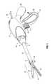
- FIG. 9is a perspective view of an end effector depicted in FIG. 1 with a knife blade lockout mechanism according to an alternate embodiment of the present disclosure
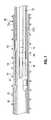
- FIG. 10is a perspective view of the knife blade lockout mechanism depicted in FIG. 9 ;
- FIG. 11is a perspective view of the knife blade lockout mechanism shown in an engaged configuration
- FIG. 12is a side view of the end effector depicted in FIG. 9 with the knife blade lockout mechanism shown in the engaged configuration;
- FIG. 13is a side view of the end effector depicted in FIG. 9 with the knife blade lockout mechanism shown in a disengaged configuration;
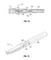
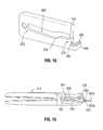
- FIG. 14is a perspective view of an end effector with a knife blade lockout mechanism according to another embodiment of the present disclosure.
- FIG. 15is a perspective view of the knife blade lockout mechanism depicted in FIG. 14 ;
- FIG. 16is a side view of the end effector depicted in FIG. 14 with the knife blade lockout mechanism shown in the engaged configuration;
- FIG. 17is a partial, side view of the end effector depicted in FIG. 14 with the knife blade lockout mechanism shown in a disengaged configuration.
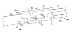
- FIG. 1an electrosurgical endoscopic forceps 2 configured for use with a knife blade lockout mechanism 40 (mechanism 40 , see FIG. 3 ) is illustrated.
- Forceps 2is provided having a longitudinal axis “A-A” defined therethrough, a housing 4 , a handle assembly 6 , a rotating assembly 8 , a trigger assembly 10 and an end effector assembly 12 .
- Forceps 2further includes a shaft 14 having a distal end 16 configured to mechanically engage end effector assembly 12 and a proximal end 18 that mechanically engages housing 4 .
- Forceps 2also includes electrosurgical cable 20 that connects forceps 2 to a generator (not shown) or other suitable power source, although forceps 2 may alternatively be configured as a battery powered instrument.
- Cable 20includes a wire (or wires) (not explicitly shown) extending therethrough that has sufficient length to extend through shaft 14 in order to provide electrosurgical energy, e.g., electrical energy, to one or both of a pair of jaw members 22 and 24 of end effector assembly 12 .
- the jaw members 22 and 24may be configured to treat tissue with ultrasonic energy, thermal energy, mechanical energy or combinations thereof.
- the mechanism 40is described herein configured for use with an endoscopic forceps 2 , it is within the purview of the present disclosure to configure the mechanism 40 for use with open style forceps.
- Rotating assembly 8is rotatable in either direction about longitudinal axis “A-A” to rotate end effector 12 about longitudinal axis “A-A,” FIG. 1 .
- Housing 4houses the internal working components of forceps 2 , such as a drive assembly (not explicitly shown), working components of the handle assembly 6 , electrical raceways associated with the cable 20 , and other working components therein.
- handle assembly 6includes a fixed handle 26 and a moveable handle 28 .
- Fixed handle 26is integrally associated with housing 4 and handle 28 is moveable relative to fixed handle 26 .
- Moveable handle 28 of handle assembly 6is ultimately connected to the drive assembly such that, together, handle 28 and drive assembly mechanically cooperate to impart movement of jaw members 22 and 24 between a spaced-apart position and a clamping position to grasp tissue disposed between sealing surfaces 30 and 32 of jaw members 22 , 24 , respectively.
- moveable handle 28is initially spaced-apart from fixed handle 26 and, correspondingly, jaw members 22 , 24 are in the spaced-apart position ( FIGS. 1-3 ).
- Moveable handle 28is depressible from this initial position to a depressed position (not explicitly shown) corresponding to the approximated position of jaw members 22 , 24 ( FIG. 8 illustrates the jaw members 22 , 24 in a partially approximated position.
- shaft 14is illustrated.
- the housing 4 and rotating assembly 8are removed to better illustrate the shaft 14 and operative components associated therewith.
- Shaft 14includes a generally elongated configuration and is configured to support the jaw members 22 , 24 at a distal end 16 thereof via a pivot pin 34 ( FIGS. 1-3 and 8 ).
- Shaft 14is also configured to provide passage of a drive tube 38 ( FIGS. 2-3 and 5-7 ) therethrough to move the jaw members 22 , 24 from the spaced-apart position to the clamping position.
- Shaft 14includes a generally elongated slot 15 of suitable configuration ( FIGS. 2, 5 and 7 ) to allow the mechanism 40 (or top portion thereof) to pivot therethrough when the mechanism 40 is moved into engagement with a knife blade assembly 50 (see FIGS. 2 and 5 ), described in greater detail below.
- Drive tube 38( FIGS. 2-3, 5 and 7 ) is operably coupled to the drive assembly to effect movement of the jaw members 22 , 24 and to move the mechanism 40 into and out of engagement with knife blade assembly 50 , described in greater detail below.
- drive tube 38includes a tubular configuration and couples to the movable handle 28 via one or more components including, but not limited to, gears, links, sleeves, etc. (not shown).
- Drive tube 38is configured to translate through the shaft 14 when the movable handle 28 is moved from its initial position to the depressed position.
- Drive tube 38couples the jaw members 22 , 24 via a cam pin 44 ( FIG. 8 ).
- cam pin 44is positioned within respective cam slots 46 and 48 on the jaw members 22 , 24 (see FIG. 3 in combination with FIG. 8 ).
- the jaw members 22 , 24may be opened and closed via a linkage system (not shown) or the like.
- the linkage systemcan be housed within the housing 4 and coupled to the movable handle 28 by one or more suitable coupling methods to effect movement of one or both of the jaw members 22 , 24 .
- Drive tube 38includes a first slot 52 that is in vertical registration with the slot 15 on the shaft 14 ( FIGS. 5 and 7 ) to allow the mechanism 40 (or top portion thereof) to pivot therethrough when the mechanism 40 is moved into engagement with a knife blade assembly 50 (see FIGS. 2-3 and 5 ), described in greater detail below.
- the cam slot 52may be configured to allow the mechanism 40 to be assembled into the drive tube 38 . As can be appreciated, this can reduce the overall manufacturing costs of the forceps 2 .
- Drive tube 38includes a pair of second slots 54 ( FIG. 3 illustrates one (1) of the two (2) slots 54 ) of suitable configuration that are configured to house a pivot pin 56 ( FIG. 3 ) therein such that the mechanism 40 is pivotable thereabout when the drive tube 38 is translated in either the proximal or distal direction.
- the second slots 54are oriented approximately 90° from the slots 52 and 15 on the respective drive tube 38 and shaft 14 , and 180 ′ from one another; this facilitates pivoting of the mechanism 40 about the pivot pin 56 .
- a distal end of the second slots 54may be configured to function as a hard stop for the jaw members 22 , 24 to provide a predetermined gap distance between the jaw members 22 , 24 when the jaw members 22 , 24 are in the clamping position.
- mechanism 40is in operative communication with the knife blade assembly 50 .
- Mechanism 40includes a generally rectangular configuration that compliments the shape of the knife blade assembly 50 ( FIGS. 4-8 ).
- Mechanism 40includes open leading and trailing ends 58 and 60 , respectively.
- Open leading end 58is configured to selectively engage a notched portion 62 of the knife, blade assembly 50 ( FIG. 4 ).
- the open leading end 58includes a finger portion 64 that extends laterally across the longitudinal axis “A-A” from a left sidewall 66 of the mechanism 40 thus forming a generally “L” shape ( FIGS. 4 and 6 ).
- open leading end 58may include, for example, one or more other configurations and/or structures to facilitate engagement of the open leading end 58 with the notched portion 62 ; a detailed description of these embodiments is discussed below.
- Mechanism 40includes an elongated cam slot 68 having proximal and distal ends, 70 and 72 , respectively ( FIGS. 4 and 6 ).
- a ramp portion 76(as best seen in FIG. 6 ) is disposed between the respective proximal and distal ends 70 and 72 and is configured to pivot the mechanism 40 about the pivot pin 56 when a cam pin 78 that is housed within the cam slot 68 comes in contact with the ramp portion 76 .
- An aperture 77(shown in phantom in FIG. 4 ) of suitable proportion is provided on the mechanism 40 and is configured to receive the pivot pin 56 therethrough such that the mechanism 40 is free to pivot thereabout when the cam pin 78 contacts the ramp portion 76 .
- Cam pin 78( FIGS. 3-8 ) is operably coupled to the drive tube 38 via one or more suitable coupling methods.
- cam pin 78is ultrasonically welded to the drive tube 38 .
- Proximal translation of the drive tube 38translates the cam pin 78 within the elongated slot 68 from the distal end 72 (corresponding to the jaw members 22 , 24 being in the open configuration and the mechanism 40 engaged with the knife blade assembly 50 , see FIGS. 3 and 4 ) towards the proximal end 70 (corresponding to the jaw members 22 , 24 being in the clamping configuration and the mechanism 40 disengaged from the knife blade assembly, see FIGS. 6 and 8 ).
- the cam pin 78Prior to the cam pin 78 reaching the proximal end 72 , the cam pin 78 contacts the ramp portion 76 , which, in turn, causes the mechanism 40 to pivot about the pivot pin 56 , which, in turn, causes the finger portion 64 to disengage from the notched portion 62 of the knife blade assembly 50 .
- the knife blade 51 of the knife blade assembly 50is free to translate within a pair of knife blade channels 53 disposed on the jaw members 22 , 24 of the end effector 12 ( FIGS. 2-3 and 8 ).
- end effector assembly 12is designed as a bilateral assembly, i.e., where both jaw member 22 and jaw member 24 are moveable about pivot pin 34 relative to one another and to shaft 14 .
- end effector assembly 12may alternatively be configured as a unilateral assembly, i.e., where jaw member 24 is fixed relative to shaft 14 and jaw member 22 is moveable about pivot pin 34 relative to shaft 14 and fixed jaw member 24 .
- the knife blade channels 53 on the jaw members 22 , 24are aligned with the knife blade assembly 50 to accommodate reciprocation of the knife blade 52 therethrough when a trigger 11 of the trigger assembly 10 is moved proximally ( FIG. 8 ).
- Knife blade assembly 50is disposed within shaft 14 and is translatable therethrough from an initial retracted configuration to an extended configuration into the knife blade channels 53 on the jaw members 22 , 24 .
- Knife blade assembly 50includes a generally elongated configuration having a split or bifurcated medial portion 55 including two legs 55 a and 55 b defining an opening 57 therebetween that is configured to receive the pivot pin 56 and cam pin 78 therethrough ( FIGS. 4-8 ).
- the opening 57is configured to permit translation of the knife blade assembly through the mechanism 40 while allowing the mechanism 40 to pivot about the pivot pin 56 and the cam pin 78 to translate within the elongated cam slot 68 when the trigger 11 is moved proximally.
- a knife blade assembly return spring 36( FIGS. 2, 5 and 7 ) is supported on the shaft 14 .
- the knife blade assembly return spring 36is utilized to return the knife blade assembly 50 including the knife blade 51 to the initial retracted configuration when the trigger 11 is released.
- drive tube 38is, initially, in an extended configuration and the jaw members 22 and 24 are an open configuration to receive or position tissue therebetween ( FIGS. 1-3 ).
- the cam pin 78is positioned at the distal end 72 of the elongated cam slot 68 and the finger 64 of the mechanism 40 is engaged with the notched portion 62 of the knife blade assembly 50 .
- the finger 64 of the mechanism 40is engaged with the notched portion 62 , the knife blade assembly 50 including the knife blade 51 is prevented from moving.
- the unique configuration of the mechanism 40overcomes aforementioned drawbacks discussed above that are typically associated with conventional forceps.
- the likelihood of the knife blade assembly 50 including the knife blade 51 inadvertently moving between the jaw members 22 , 24 , such as, for example, when large tissue is positioned therebetween,is greatly reduced, if not completely eliminated. In other words, this greatly reduces, if not completely eliminates “blade trap” from occurring.
- the mechanism 40when the mechanism 40 is engaged with the knife blade assembly 50 , the mechanism 40 could be used to limit the travel of the knife blade assembly 50 .
- the knife blade assembly 50could deploy partially, but not beyond a “safe” distance where the knife blade assembly 50 is at risk of becoming trapped between the jaw members 22 , 24 . As can be appreciated, this may prevent a surgeon from becoming frustrated (or confused) that the knife blade assembly 50 cannot be deployed and would maintain partial functionality of the knife blade assembly 50 even on thick tissue.
- the movable handle 28is approximated toward the fixed handle 26 . Approximation of the movable handle 28 causes the drive tube 38 to move proximally, which has a two-fold effect. One, the drive tube 38 moves the cam pin 44 ( FIGS. 1 and 8 ) proximally, which, in turn, moves the jaw members 22 , 24 toward one another and the clamping configuration.
- the drive tube 38moves the cam pin 78 proximally towards the proximal end 70 until such time that the cam pin 78 contacts the ramp portion 76 , which, in turn, causes the mechanism 40 to pivot about the pivot pin 56 , which, in turn, causes the finger portion 64 to disengage from the notched portion 62 of the knife blade assembly 50 .
- the knife blade 51 of the knife blade assembly 50is free to translate within a pair of knife blade channels 53 disposed on the jaw members 22 , 24 of the end effector 12 ( FIGS. 2-3 and 8 ).
- a mechanism 140according to an alternate embodiment of the present disclosure is illustrated that may be utilized with the forceps 2 . Only those operative features that are unique to the functionality of the mechanism 140 are described herein.
- mechanism 140is positioned between the jaw members 122 , 124 of the end effector 112 ( FIGS. 9, 12 and 13 ). Moreover, unlike mechanism 40 that utilized its own pivot pin 56 and cam pin 78 , mechanism 140 is operably coupled to the pivot pin 134 and cam pin 144 that are configured to function in a manner described above ( FIG. 9 ). Further, in the embodiment illustrated in FIGS. 9-14 , the elongated cam slot 168 is disposed proximal with respect to the aperture 177 , i.e., pivot pin 134 is disposed distal with respect to cam pin 144 ( FIG. 10 ). Finger 64 is replaced by a bottom wall 164 ( FIG. 10 ) that is configured to engage the notched portion 162 of the knife blade assembly 150 . Bottom wall 164 is positioned at the open trailing end 158 as opposed to the finger 64 that is positioned at the open leading end 60 .
- the drive tube 38is, initially, in an extended configuration and the jaw members 122 and 124 are in an open configuration to receive or position tissue therebetween ( FIGS. 9-10 and 12 ).
- the cam pin 144is positioned at the distal end 172 of the elongated cam slot 168 and the bottom wall 164 of the mechanism 140 is engaged with the notched portion 162 ( FIG. 11 ) of the knife blade assembly 150 .
- the knife blade assembly 150 including the knife blade 151is prevented from moving ( FIG. 12 ).
- the movable handle 28is approximated toward the fixed handle 26 .
- Approximation of the movable handle 28causes the drive tube 38 to move proximally, which has a two-fold effect.
- the drive tube 38moves the cam pin 144 proximally, which, in turn, moves the jaw members 122 , 124 toward one another and to the clamping configuration.
- the drive tube 38moves the cam pin 144 proximally towards the proximal end 170 until such time that the cam pin 144 contacts the ramp portion 176 ( FIG.
- a mechanism 240according to another alternate embodiment of the present disclosure is illustrated that may be utilized with the forceps 2 . Only those operative features that are unique to the functionality of the mechanism 240 are described herein.
- mechanism 240includes a protrusion 264 ( FIG. 15 ) that is configured to engage the notch 262 to prevent the knife blade assembly 250 from moving ( FIG. 16 ).
- Protrusion 264includes a generally arcuate configuration and is positioned at the open trailing end 260 .
- a slit 265is provided at a top surface of the protrusion 264 and is configured to releasably engage a portion of the notched portion 262 (e.g., adjacent the bifurcated leg 255 b ) such that a press-fit, friction-fit, etc. is created therebetween.
- this press or friction-fitfacilitates maintaining the protrusion 264 and notched portion 262 in substantial alignment with one another.
- the drive tube 38is, initially, in an extended configuration and the jaw members 222 and 224 are an open configuration to position tissue therebetween ( FIG. 16 ).
- the cam pin 244is positioned at the distal end 272 of the elongated cam slot 268 and the protrusion 264 of the mechanism 240 is engaged with the notched portion 262 of the knife blade assembly 250 ( FIG. 16 ).
- the knife blade assembly 250FIG. 14
- the knife blade 251FIGS. 16-17
- the movable handle 28is approximated toward the fixed handle 26 .
- Approximation of the movable handle 28causes the drive tube 38 to move proximally, which has a two-fold effect.
- the drive tube 38moves the cam pin 244 proximally, which, in turn, moves the jaw members 222 , 224 toward one another and the clamping configuration.
- the drive tube 38moves the cam pin 244 proximally towards the proximal end 270 until such time that the cam pin 244 contacts the ramp portion 276 ( FIG.
- one or more resilient memberssuch as, for example, a spring or the like may be operably coupled to any of the aforementioned mechanisms 40 , 140 , 240 to facilitate pivoting thereof about the respective pivot pins 56 , 134 , 234 .
Landscapes
- Health & Medical Sciences (AREA)
- Surgery (AREA)
- Life Sciences & Earth Sciences (AREA)
- Engineering & Computer Science (AREA)
- Biomedical Technology (AREA)
- Public Health (AREA)
- Nuclear Medicine, Radiotherapy & Molecular Imaging (AREA)
- Veterinary Medicine (AREA)
- General Health & Medical Sciences (AREA)
- Heart & Thoracic Surgery (AREA)
- Medical Informatics (AREA)
- Molecular Biology (AREA)
- Animal Behavior & Ethology (AREA)
- Physics & Mathematics (AREA)
- Otolaryngology (AREA)
- Plasma & Fusion (AREA)
- Ophthalmology & Optometry (AREA)
- Surgical Instruments (AREA)
Abstract
Description
Claims (21)
Priority Applications (2)
| Application Number | Priority Date | Filing Date | Title |
|---|---|---|---|
| US14/604,320US9610116B2 (en) | 2011-11-30 | 2015-01-23 | Electrosurgical instrument with a knife blade lockout mechanism |
| US15/461,153US10595932B2 (en) | 2011-11-30 | 2017-03-16 | Electrosurgical instrument with a knife blade lockout mechanism |
Applications Claiming Priority (2)
| Application Number | Priority Date | Filing Date | Title |
|---|---|---|---|
| US13/308,104US8968310B2 (en) | 2011-11-30 | 2011-11-30 | Electrosurgical instrument with a knife blade lockout mechanism |
| US14/604,320US9610116B2 (en) | 2011-11-30 | 2015-01-23 | Electrosurgical instrument with a knife blade lockout mechanism |
Related Parent Applications (1)
| Application Number | Title | Priority Date | Filing Date |
|---|---|---|---|
| US13/308,104ContinuationUS8968310B2 (en) | 2011-11-30 | 2011-11-30 | Electrosurgical instrument with a knife blade lockout mechanism |
Related Child Applications (1)
| Application Number | Title | Priority Date | Filing Date |
|---|---|---|---|
| US15/461,153ContinuationUS10595932B2 (en) | 2011-11-30 | 2017-03-16 | Electrosurgical instrument with a knife blade lockout mechanism |
Publications (2)
| Publication Number | Publication Date |
|---|---|
| US20150133931A1 US20150133931A1 (en) | 2015-05-14 |
| US9610116B2true US9610116B2 (en) | 2017-04-04 |
Family
ID=48467518
Family Applications (3)
| Application Number | Title | Priority Date | Filing Date |
|---|---|---|---|
| US13/308,104Active2033-09-01US8968310B2 (en) | 2011-11-30 | 2011-11-30 | Electrosurgical instrument with a knife blade lockout mechanism |
| US14/604,320Active2031-12-01US9610116B2 (en) | 2011-11-30 | 2015-01-23 | Electrosurgical instrument with a knife blade lockout mechanism |
| US15/461,153Active2032-07-19US10595932B2 (en) | 2011-11-30 | 2017-03-16 | Electrosurgical instrument with a knife blade lockout mechanism |
Family Applications Before (1)
| Application Number | Title | Priority Date | Filing Date |
|---|---|---|---|
| US13/308,104Active2033-09-01US8968310B2 (en) | 2011-11-30 | 2011-11-30 | Electrosurgical instrument with a knife blade lockout mechanism |
Family Applications After (1)
| Application Number | Title | Priority Date | Filing Date |
|---|---|---|---|
| US15/461,153Active2032-07-19US10595932B2 (en) | 2011-11-30 | 2017-03-16 | Electrosurgical instrument with a knife blade lockout mechanism |
Country Status (1)
| Country | Link |
|---|---|
| US (3) | US8968310B2 (en) |
Cited By (3)
| Publication number | Priority date | Publication date | Assignee | Title |
|---|---|---|---|---|
| US10595932B2 (en) | 2011-11-30 | 2020-03-24 | Covidien Lp | Electrosurgical instrument with a knife blade lockout mechanism |
| US10813683B2 (en) | 2013-01-29 | 2020-10-27 | Ethicon Llc | Bipolar electrosurgical hand shears |
| US11134970B2 (en) | 2018-04-10 | 2021-10-05 | Gyrus Acmi, Inc. | Forceps knife blade lockout mechanism |
Families Citing this family (89)
| Publication number | Priority date | Publication date | Assignee | Title |
|---|---|---|---|---|
| US7364577B2 (en) | 2002-02-11 | 2008-04-29 | Sherwood Services Ag | Vessel sealing system |
| ES2262639T3 (en) | 2001-04-06 | 2006-12-01 | Sherwood Services Ag | SHUTTER AND DIVIDER OF GLASSES WITH BUMPER MEMBERS N OCONDUCTIVES. |
| US7628791B2 (en) | 2005-08-19 | 2009-12-08 | Covidien Ag | Single action tissue sealer |
| US8298232B2 (en) | 2006-01-24 | 2012-10-30 | Tyco Healthcare Group Lp | Endoscopic vessel sealer and divider for large tissue structures |
| ES2442241T3 (en) | 2008-03-31 | 2014-02-10 | Applied Medical Resources Corporation | Electrosurgical system with a switching mechanism |
| US8357158B2 (en) | 2008-04-22 | 2013-01-22 | Covidien Lp | Jaw closure detection system |
| US8114122B2 (en) | 2009-01-13 | 2012-02-14 | Tyco Healthcare Group Lp | Apparatus, system, and method for performing an electrosurgical procedure |
| US8187273B2 (en) | 2009-05-07 | 2012-05-29 | Tyco Healthcare Group Lp | Apparatus, system, and method for performing an electrosurgical procedure |
| US8430876B2 (en) | 2009-08-27 | 2013-04-30 | Tyco Healthcare Group Lp | Vessel sealer and divider with knife lockout |
| US8357159B2 (en) | 2009-09-03 | 2013-01-22 | Covidien Lp | Open vessel sealing instrument with pivot assembly |
| US8133254B2 (en) | 2009-09-18 | 2012-03-13 | Tyco Healthcare Group Lp | In vivo attachable and detachable end effector assembly and laparoscopic surgical instrument and methods therefor |
| US8112871B2 (en) | 2009-09-28 | 2012-02-14 | Tyco Healthcare Group Lp | Method for manufacturing electrosurgical seal plates |
| US8409246B2 (en)* | 2010-06-02 | 2013-04-02 | Covidien Lp | Apparatus for performing an electrosurgical procedure |
| AU2011308509B8 (en) | 2010-10-01 | 2015-04-02 | Applied Medical Resources Corporation | Electrosurgical instrument |
| US9844384B2 (en) | 2011-07-11 | 2017-12-19 | Covidien Lp | Stand alone energy-based tissue clips |
| US8864795B2 (en) | 2011-10-03 | 2014-10-21 | Covidien Lp | Surgical forceps |
| US8968309B2 (en) | 2011-11-10 | 2015-03-03 | Covidien Lp | Surgical forceps |
| US8968360B2 (en) | 2012-01-25 | 2015-03-03 | Covidien Lp | Surgical instrument with resilient driving member and related methods of use |
| US8747434B2 (en) | 2012-02-20 | 2014-06-10 | Covidien Lp | Knife deployment mechanisms for surgical forceps |
| US8887373B2 (en) | 2012-02-24 | 2014-11-18 | Covidien Lp | Vessel sealing instrument with reduced thermal spread and method of manufacture therefor |
| US8961514B2 (en) | 2012-03-06 | 2015-02-24 | Covidien Lp | Articulating surgical apparatus |
| US9078653B2 (en) | 2012-03-26 | 2015-07-14 | Ethicon Endo-Surgery, Inc. | Surgical stapling device with lockout system for preventing actuation in the absence of an installed staple cartridge |
| US9375282B2 (en) | 2012-03-26 | 2016-06-28 | Covidien Lp | Light energy sealing, cutting and sensing surgical device |
| US9265569B2 (en) | 2012-03-29 | 2016-02-23 | Covidien Lp | Method of manufacturing an electrosurgical forceps |
| US9668807B2 (en) | 2012-05-01 | 2017-06-06 | Covidien Lp | Simplified spring load mechanism for delivering shaft force of a surgical instrument |
| US9820765B2 (en) | 2012-05-01 | 2017-11-21 | Covidien Lp | Surgical instrument with stamped double-flange jaws |
| US8968311B2 (en) | 2012-05-01 | 2015-03-03 | Covidien Lp | Surgical instrument with stamped double-flag jaws and actuation mechanism |
| US9375258B2 (en) | 2012-05-08 | 2016-06-28 | Covidien Lp | Surgical forceps |
| US9039731B2 (en) | 2012-05-08 | 2015-05-26 | Covidien Lp | Surgical forceps including blade safety mechanism |
| US9192421B2 (en) | 2012-07-24 | 2015-11-24 | Covidien Lp | Blade lockout mechanism for surgical forceps |
| US9265566B2 (en) | 2012-10-16 | 2016-02-23 | Covidien Lp | Surgical instrument |
| US9877775B2 (en)* | 2013-03-12 | 2018-01-30 | Covidien Lp | Electrosurgical instrument with a knife blade stop |
| USD788302S1 (en) | 2013-10-01 | 2017-05-30 | Covidien Lp | Knife for endoscopic electrosurgical forceps |
| WO2015176074A2 (en) | 2014-05-16 | 2015-11-19 | Applied Medical Resources Corporation | Electrosurgical system |
| JP6735272B2 (en) | 2014-05-30 | 2020-08-05 | アプライド メディカル リソーシーズ コーポレイション | Electrosurgical sealing and incision system |
| US10045781B2 (en)* | 2014-06-13 | 2018-08-14 | Ethicon Llc | Closure lockout systems for surgical instruments |
| CN104068906B (en)* | 2014-07-22 | 2017-02-15 | 李洪湘 | Disposable injection loop ligaturing curer |
| US9987076B2 (en) | 2014-09-17 | 2018-06-05 | Covidien Lp | Multi-function surgical instruments |
| US9877777B2 (en) | 2014-09-17 | 2018-01-30 | Covidien Lp | Surgical instrument having a bipolar end effector assembly and a deployable monopolar assembly |
| US9918785B2 (en) | 2014-09-17 | 2018-03-20 | Covidien Lp | Deployment mechanisms for surgical instruments |
| US10080605B2 (en) | 2014-09-17 | 2018-09-25 | Covidien Lp | Deployment mechanisms for surgical instruments |
| US10039592B2 (en) | 2014-09-17 | 2018-08-07 | Covidien Lp | Deployment mechanisms for surgical instruments |
| KR102545505B1 (en) | 2014-12-23 | 2023-06-20 | 어플라이드 메디컬 리소시스 코포레이션 | Bipolar Electrosurgical Sealers and Dividers |
| US10172612B2 (en) | 2015-01-21 | 2019-01-08 | Covidien Lp | Surgical instruments with force applier and methods of use |
| USD844139S1 (en) | 2015-07-17 | 2019-03-26 | Covidien Lp | Monopolar assembly of a multi-function surgical instrument |
| USD844138S1 (en) | 2015-07-17 | 2019-03-26 | Covidien Lp | Handle assembly of a multi-function surgical instrument |
| US10219818B2 (en)* | 2015-07-24 | 2019-03-05 | Covidien Lp | Shaft-based surgical forceps and method of manufacturing the same |
| US12433574B2 (en) | 2015-09-15 | 2025-10-07 | Cook Medical Technologies Llc | Locking forceps |
| WO2017048594A1 (en) | 2015-09-15 | 2017-03-23 | Cook Medical Technologies Llc | Forceps with locking mechanism |
| US10537381B2 (en) | 2016-02-26 | 2020-01-21 | Covidien Lp | Surgical instrument having a bipolar end effector assembly and a deployable monopolar assembly |
| US10765471B2 (en) | 2016-04-15 | 2020-09-08 | Bolder Surgical, Llc | Electrosurgical sealer and divider |
| US10631887B2 (en) | 2016-08-15 | 2020-04-28 | Covidien Lp | Electrosurgical forceps for video assisted thoracoscopic surgery and other surgical procedures |
| US10813695B2 (en) | 2017-01-27 | 2020-10-27 | Covidien Lp | Reflectors for optical-based vessel sealing |
| WO2018185815A1 (en)* | 2017-04-03 | 2018-10-11 | オリンパス株式会社 | Heat treatment tool |
| US11172980B2 (en) | 2017-05-12 | 2021-11-16 | Covidien Lp | Electrosurgical forceps for grasping, treating, and/or dividing tissue |
| US10973567B2 (en) | 2017-05-12 | 2021-04-13 | Covidien Lp | Electrosurgical forceps for grasping, treating, and/or dividing tissue |
| USD843574S1 (en) | 2017-06-08 | 2019-03-19 | Covidien Lp | Knife for open vessel sealer |
| USD854684S1 (en) | 2017-06-08 | 2019-07-23 | Covidien Lp | Open vessel sealer with mechanical cutter |
| USD854149S1 (en) | 2017-06-08 | 2019-07-16 | Covidien Lp | End effector for open vessel sealer |
| US11154348B2 (en) | 2017-08-29 | 2021-10-26 | Covidien Lp | Surgical instruments and methods of assembling surgical instruments |
| US20190246985A1 (en)* | 2018-02-13 | 2019-08-15 | Covidien Lp | Clamping device for detecting internal blood pressure |
| US11241275B2 (en) | 2018-03-21 | 2022-02-08 | Covidien Lp | Energy-based surgical instrument having multiple operational configurations |
| US11123132B2 (en) | 2018-04-09 | 2021-09-21 | Covidien Lp | Multi-function surgical instruments and assemblies therefor |
| US10828756B2 (en) | 2018-04-24 | 2020-11-10 | Covidien Lp | Disassembly methods facilitating reprocessing of multi-function surgical instruments |
| US10780544B2 (en)* | 2018-04-24 | 2020-09-22 | Covidien Lp | Systems and methods facilitating reprocessing of surgical instruments |
| JP7610777B2 (en) | 2018-09-05 | 2025-01-09 | アプライド メディカル リソーシーズ コーポレイション | Electrosurgical Generator Control System |
| AU2019337548B2 (en)* | 2018-09-14 | 2021-12-09 | Covidien Lp | Articulating blade deployment |
| USD904611S1 (en) | 2018-10-10 | 2020-12-08 | Bolder Surgical, Llc | Jaw design for a surgical instrument |
| US11471211B2 (en) | 2018-10-12 | 2022-10-18 | Covidien Lp | Electrosurgical forceps |
| US11376062B2 (en) | 2018-10-12 | 2022-07-05 | Covidien Lp | Electrosurgical forceps |
| US11696796B2 (en) | 2018-11-16 | 2023-07-11 | Applied Medical Resources Corporation | Electrosurgical system |
| US11350982B2 (en) | 2018-12-05 | 2022-06-07 | Covidien Lp | Electrosurgical forceps |
| US11523861B2 (en) | 2019-03-22 | 2022-12-13 | Covidien Lp | Methods for manufacturing a jaw assembly for an electrosurgical forceps |
| AU2020253238B2 (en) | 2019-03-29 | 2025-03-06 | Gyrus Acmi, Inc. D/B/A Olympus Surgical Technologies America | Forceps motion transfer assembly |
| US12402934B2 (en) | 2019-09-15 | 2025-09-02 | Covidien Lp | Electrosurgical instrument for grasping, treating, and/or dividing tissue incorporating thermal management feature |
| US11622804B2 (en) | 2020-03-16 | 2023-04-11 | Covidien Lp | Forceps with linear trigger mechanism |
| US12295641B2 (en) | 2020-07-01 | 2025-05-13 | Covidien Lp | Electrosurgical forceps with swivel action nerve probe |
| US11660109B2 (en) | 2020-09-08 | 2023-05-30 | Covidien Lp | Cutting elements for surgical instruments such as for use in robotic surgical systems |
| US12185964B2 (en) | 2020-09-10 | 2025-01-07 | Covidien Lp | End effector assemblies for surgical instruments such as for use in robotic surgical systems |
| US12161386B2 (en) | 2020-09-11 | 2024-12-10 | Covidien Lp | Surgical instruments having an articulating section such as for use in robotic surgical systems |
| US11925406B2 (en) | 2020-09-14 | 2024-03-12 | Covidien Lp | End effector assemblies for surgical instruments |
| US11931025B2 (en) | 2020-10-29 | 2024-03-19 | Cilag Gmbh International | Surgical instrument comprising a releasable closure drive lock |
| EP4079240B1 (en)* | 2021-04-19 | 2023-11-15 | Erbe Elektromedizin GmbH | Blade cartridge for a surgical instrument |
| US12279845B2 (en) | 2021-10-18 | 2025-04-22 | Cilag Gmbh International | Cable-driven actuation system for robotic surgical tool attachment |
| US12251105B2 (en) | 2021-10-20 | 2025-03-18 | Cilag Gmbh International | Lockout arrangements for surgical instruments |
| WO2023068381A1 (en)* | 2021-10-21 | 2023-04-27 | Olympus Corporation | Medical intervention device with versatile handle |
| CN114191069B (en)* | 2021-12-06 | 2024-01-12 | 安瑞医疗器械(杭州)有限公司 | Hemostatic forceps and clamp parts thereof |
| CN114376676B (en)* | 2021-12-31 | 2025-01-21 | 杭州德柯医疗科技有限公司 | Rotational synchronized puncture clamp |
| CN114376678B (en)* | 2021-12-31 | 2025-01-21 | 杭州德柯医疗科技有限公司 | Automatic synchronized puncture clamp |
Citations (224)
| Publication number | Priority date | Publication date | Assignee | Title |
|---|---|---|---|---|
| SU401367A1 (en) | 1971-10-05 | 1973-10-12 | Тернопольский государственный медицинский институт | BIAKTIVNYE ELECTRO SURGICAL INSTRUMENT |
| DE2415263A1 (en) | 1974-03-29 | 1975-10-02 | Aesculap Werke Ag | Surgical H.F. coagulation probe has electrode tongs - with exposed ends of insulated conductors forming tong-jaws |
| DE2514501A1 (en) | 1975-04-03 | 1976-10-21 | Karl Storz | Bipolar coagulation instrument for endoscopes - has two high frequency electrodes looped over central insulating piece |
| DE2627679A1 (en) | 1975-06-26 | 1977-01-13 | Marcel Lamidey | HEMATISTIC HIGH FREQUENCY EXTRACTOR FORCEPS |
| USD249549S (en) | 1976-10-22 | 1978-09-19 | Aspen Laboratories, Inc. | Electrosurgical handle |
| USD263020S (en) | 1980-01-22 | 1982-02-16 | Rau Iii David M | Retractable knife |
| JPS61501068A (en) | 1984-01-30 | 1986-05-29 | ハルコフスキイ ナウチノ−イススレドワテルスキイ インスチチユ−ト オブスチエイ イ ネオトロジノイ ヒルルギイ | bipolar electrosurgical instrument |
| DE3423356C2 (en) | 1984-06-25 | 1986-06-26 | Berchtold Medizin-Elektronik GmbH & Co, 7200 Tuttlingen | Electrosurgical high frequency cutting instrument |
| DE3612646A1 (en) | 1985-04-16 | 1987-04-30 | Ellman International | Electrosurgical handle piece for blades, needles and forceps |
| DE8712328U1 (en) | 1987-09-11 | 1988-02-18 | Jakoubek, Franz, 7201 Emmingen-Liptingen | Endoscopy forceps |
| USD295894S (en) | 1985-09-26 | 1988-05-24 | Acme United Corporation | Disposable surgical scissors |
| USD295893S (en) | 1985-09-25 | 1988-05-24 | Acme United Corporation | Disposable surgical clamp |
| USD298353S (en) | 1986-05-06 | 1988-11-01 | Vitalmetrics, Inc. | Handle for surgical instrument |
| USD299413S (en) | 1985-07-17 | 1989-01-17 | The Stanley Works | Folding pocket saw handle |
| JPH055106A (en) | 1990-07-31 | 1993-01-14 | Matsushita Electric Works Ltd | Production of alloy sintered body |
| JPH0540112A (en) | 1991-02-08 | 1993-02-19 | Tokico Ltd | Sample liquid component analyzer |
| USD343453S (en) | 1993-05-05 | 1994-01-18 | Laparomed Corporation | Handle for laparoscopic surgical instrument |
| JPH0630945A (en) | 1992-05-19 | 1994-02-08 | Olympus Optical Co Ltd | Suturing apparatus |
| JPH06502328A (en) | 1990-10-17 | 1994-03-17 | ボストン サイエンティフィック コーポレイション | Surgical instruments and methods |
| JPH06121797A (en) | 1992-02-27 | 1994-05-06 | United States Surgical Corp | Equipment and method for performing intracutaneous stapling of body tissue |
| USD348930S (en) | 1991-10-11 | 1994-07-19 | Ethicon, Inc. | Endoscopic stapler |
| USD349341S (en) | 1992-10-28 | 1994-08-02 | Microsurge, Inc. | Endoscopic grasper |
| JPH06285078A (en) | 1993-04-05 | 1994-10-11 | Olympus Optical Co Ltd | Forceps |
| JPH06343644A (en) | 1993-05-04 | 1994-12-20 | Gyrus Medical Ltd | Surgical peritoneoscope equipment |
| JPH06511401A (en) | 1991-06-07 | 1994-12-22 | バイタル メディカル プロダクツ コーポレイション | Bipolar electrosurgical endoscopic instrument and its method of use |
| USD354564S (en) | 1993-06-25 | 1995-01-17 | Richard-Allan Medical Industries, Inc. | Surgical clip applier |
| DE4303882C2 (en) | 1993-02-10 | 1995-02-09 | Kernforschungsz Karlsruhe | Combination instrument for separation and coagulation for minimally invasive surgery |
| USD358887S (en) | 1993-12-02 | 1995-05-30 | Cobot Medical Corporation | Combined cutting and coagulating forceps |
| DE4403252A1 (en) | 1994-02-03 | 1995-08-10 | Michael Hauser | Instrument shaft for min. invasive surgery |
| JPH07265328A (en) | 1993-11-01 | 1995-10-17 | Gyrus Medical Ltd | Electrode assembly for electric surgery device and electric surgery device using it |
| JPH0856955A (en) | 1994-06-29 | 1996-03-05 | Gyrus Medical Ltd | Electric surgical apparatus |
| DE19515914C1 (en) | 1995-05-02 | 1996-07-25 | Aesculap Ag | Tong or scissor-shaped surgical instrument |
| DE19506363A1 (en) | 1995-02-24 | 1996-08-29 | Frost Lore Geb Haupt | Non-invasive thermometry in organs under hyperthermia and coagulation conditions |
| JPH08252263A (en) | 1994-12-21 | 1996-10-01 | Gyrus Medical Ltd | Electronic surgical incision instrument and electronic surgical incision device using the same |
| JPH08289895A (en) | 1995-04-21 | 1996-11-05 | Olympus Optical Co Ltd | Suture device |
| DE29616210U1 (en) | 1996-09-18 | 1996-11-14 | Olympus Winter & Ibe Gmbh, 22045 Hamburg | Handle for surgical instruments |
| JPH08317934A (en) | 1995-04-12 | 1996-12-03 | Ethicon Endo Surgery Inc | Hemostatic device for electric surgery with adaptable electrode |
| JPH08317936A (en) | 1995-01-18 | 1996-12-03 | Ethicon Endo Surgery Inc | Hemostatic device for electric surgery provided with recessed type and/or crossed type electrode |
| JPH0910223A (en) | 1995-06-23 | 1997-01-14 | Gyrus Medical Ltd | Generator and system for electric operation |
| DE19608716C1 (en) | 1996-03-06 | 1997-04-17 | Aesculap Ag | Bipolar surgical holding instrument |
| JPH09122138A (en) | 1995-10-20 | 1997-05-13 | Ethicon Endo Surgery Inc | Apparatus for operation |
| USD384413S (en) | 1994-10-07 | 1997-09-30 | United States Surgical Corporation | Endoscopic suturing instrument |
| JPH1024051A (en) | 1995-09-20 | 1998-01-27 | Olympus Optical Co Ltd | Coagulation forceps with separating function |
| DE19751106A1 (en) | 1996-11-27 | 1998-05-28 | Eastman Kodak Co | Laser printer with array of laser diodes |
| JPH10155798A (en) | 1996-12-04 | 1998-06-16 | Asahi Optical Co Ltd | Hot biopsy forceps for endoscopes |
| USH1745H (en) | 1995-09-29 | 1998-08-04 | Paraschac; Joseph F. | Electrosurgical clamping device with insulation limited bipolar electrode |
| USD402028S (en) | 1997-10-10 | 1998-12-01 | Invasatec, Inc. | Hand controller for medical system |
| JPH1147150A (en) | 1997-08-06 | 1999-02-23 | Olympus Optical Co Ltd | Endoscopic surgery appliance |
| JPH1170124A (en) | 1997-05-14 | 1999-03-16 | Ethicon Endo Surgery Inc | Improved electrosurgical hemostatic apparatus having anvil |
| USD408018S (en) | 1996-03-12 | 1999-04-13 | Mcnaughton Patrick J | Switch guard |
| DE19751108A1 (en) | 1997-11-18 | 1999-05-20 | Beger Frank Michael Dipl Desig | Electrosurgical operation tool, especially for diathermy |
| JPH11169381A (en) | 1997-12-15 | 1999-06-29 | Olympus Optical Co Ltd | High frequency treating device |
| JPH11192238A (en) | 1997-10-10 | 1999-07-21 | Ethicon Endo Surgery Inc | Ultrasonic forceps coagulation device improved of pivot-attaching of forceps arm |
| JPH11244298A (en) | 1997-12-19 | 1999-09-14 | Gyrus Medical Ltd | Electric surgical instrument |
| USD416089S (en) | 1996-04-08 | 1999-11-02 | Richard-Allan Medical Industries, Inc. | Endoscopic linear stapling and dividing surgical instrument |
| JP2000102545A (en) | 1997-06-18 | 2000-04-11 | Eggers & Associates Inc | Electric tweezers for surgery |
| USD424694S (en) | 1998-10-23 | 2000-05-09 | Sherwood Services Ag | Forceps |
| USD425201S (en) | 1998-10-23 | 2000-05-16 | Sherwood Services Ag | Disposable electrode assembly |
| WO2000036986A1 (en) | 1998-12-18 | 2000-06-29 | Karl Storz Gmbh & Co. Kg | Bipolar medical instrument |
| USH1904H (en) | 1997-05-14 | 2000-10-03 | Ethicon Endo-Surgery, Inc. | Electrosurgical hemostatic method and device |
| WO2000059392A1 (en) | 1999-04-01 | 2000-10-12 | Erbe Elektromedizin | Surgical instrument |
| JP2000342599A (en) | 1999-05-21 | 2000-12-12 | Gyrus Medical Ltd | Generator for electrosurgical operation, electrosurgical operation system, method for operating this system and method for performing amputation and resection of tissue by electrosurgical operation |
| JP2000350732A (en) | 1999-05-21 | 2000-12-19 | Gyrus Medical Ltd | Electrosurgical system, generator for electrosurgery, and method for cutting or excising tissue by electrosurgery |
| JP2001003400A (en) | 1999-06-21 | 2001-01-09 | Sumitomo Constr Mach Co Ltd | Monitor device for hydraulic shovel |
| JP2001008944A (en) | 1999-05-28 | 2001-01-16 | Gyrus Medical Ltd | Electric surgical signal generator and electric surgical system |
| JP2001029356A (en) | 1999-06-11 | 2001-02-06 | Gyrus Medical Ltd | Electric and surgical signal generator |
| WO2001015614A1 (en) | 1999-08-27 | 2001-03-08 | Karl Storz Gmbh & Co. Kg | Bipolar medical instrument |
| JP2001128990A (en) | 1999-05-28 | 2001-05-15 | Gyrus Medical Ltd | Electro surgical instrument and electrosurgical tool converter |
| DE19946527C1 (en) | 1999-09-28 | 2001-07-12 | Storz Karl Gmbh & Co Kg | Bipolar, e.g. laparoscopic surgery instrument, cuts electrically, cauterizes and grips using simple design with high frequency current-concentrating projections |
| JP2001190564A (en) | 2000-01-12 | 2001-07-17 | Olympus Optical Co Ltd | Medical treatment instrument |
| WO2001054604A1 (en) | 2000-01-25 | 2001-08-02 | Aesculap Ag & Co. Kg | Bipolar gripping device |
| USD449886S1 (en) | 1998-10-23 | 2001-10-30 | Sherwood Services Ag | Forceps with disposable electrode |
| EP1159926A2 (en) | 2000-06-03 | 2001-12-05 | Aesculap Ag | Scissor- or forceps-like surgical instrument |
| USD453923S1 (en) | 2000-11-16 | 2002-02-26 | Carling Technologies, Inc. | Electrical rocker switch guard |
| USD454951S1 (en) | 2001-02-27 | 2002-03-26 | Visionary Biomedical, Inc. | Steerable catheter |
| USD457958S1 (en) | 2001-04-06 | 2002-05-28 | Sherwood Services Ag | Vessel sealer and divider |
| USD457959S1 (en) | 2001-04-06 | 2002-05-28 | Sherwood Services Ag | Vessel sealer |
| JP2002528166A (en) | 1998-10-23 | 2002-09-03 | シャーウッド サーヴィシス アクチェンゲゼルシャフト | Externally-opened vascular sealing forceps with disposable electrodes |
| DE10045375C2 (en) | 2000-09-14 | 2002-10-24 | Aesculap Ag & Co Kg | Medical instrument |
| USD465281S1 (en) | 1999-09-21 | 2002-11-05 | Karl Storz Gmbh & Co. Kg | Endoscopic medical instrument |
| USD466209S1 (en) | 2001-02-27 | 2002-11-26 | Visionary Biomedical, Inc. | Steerable catheter |
| JP2003245285A (en) | 2002-01-23 | 2003-09-02 | Ethicon Endo Surgery Inc | Feedback light apparatus and method for use with electrosurgical instrument |
| US20040087943A1 (en) | 2001-04-06 | 2004-05-06 | Dycus Sean T. | Vessel sealer an divider |
| JP2004517668A (en) | 2000-10-20 | 2004-06-17 | オーナックス・メディカル・インコーポレーテッド | Surgical suturing instrument and method of use |
| USD493888S1 (en) | 2003-02-04 | 2004-08-03 | Sherwood Services Ag | Electrosurgical pencil with pistol grip |
| JP2004528869A (en) | 2001-01-26 | 2004-09-24 | エシコン・エンド−サージェリィ・インコーポレイテッド | Electrosurgical instruments for coagulation and cutting |
| USD496997S1 (en) | 2003-05-15 | 2004-10-05 | Sherwood Services Ag | Vessel sealer and divider |
| USD499181S1 (en) | 2003-05-15 | 2004-11-30 | Sherwood Services Ag | Handle for a vessel sealer and divider |
| USD502994S1 (en) | 2003-05-21 | 2005-03-15 | Blake, Iii Joseph W | Repeating multi-clip applier |
| USD509297S1 (en) | 2003-10-17 | 2005-09-06 | Tyco Healthcare Group, Lp | Surgical instrument |
| WO2005110264A2 (en) | 2004-05-14 | 2005-11-24 | Erbe Elektromedizin Gmbh | Electrosurgical instrument |
| US20060030870A1 (en) | 2004-08-03 | 2006-02-09 | Staudner Rupert A | Trocar with retractable cutting surface |
| US7001382B2 (en) | 1999-09-03 | 2006-02-21 | Conmed Corporation | Electrosurgical coagulating and cutting instrument |
| USD525361S1 (en) | 2004-10-06 | 2006-07-18 | Sherwood Services Ag | Hemostat style elongated dissecting and dividing instrument |
| USD531311S1 (en) | 2004-10-06 | 2006-10-31 | Sherwood Services Ag | Pistol grip style elongated dissecting and dividing instrument |
| US20060271042A1 (en) | 2005-05-26 | 2006-11-30 | Gyrus Medical, Inc. | Cutting and coagulating electrosurgical forceps having cam controlled jaw closure |
| USD533274S1 (en) | 2004-10-12 | 2006-12-05 | Allegiance Corporation | Handle for surgical suction-irrigation device |
| USD533942S1 (en) | 2004-06-30 | 2006-12-19 | Sherwood Services Ag | Open vessel sealer with mechanical cutter |
| USD535027S1 (en) | 2004-10-06 | 2007-01-09 | Sherwood Services Ag | Low profile vessel sealing and cutting mechanism |
| USD538932S1 (en) | 2005-06-30 | 2007-03-20 | Medical Action Industries Inc. | Surgical needle holder |
| US20070088375A1 (en) | 2004-03-23 | 2007-04-19 | Correx, Inc. | Apparatus and method for forming a hole in a hollow organ |
| USD541418S1 (en) | 2004-10-06 | 2007-04-24 | Sherwood Services Ag | Lung sealing device |
| USD541611S1 (en) | 2006-01-26 | 2007-05-01 | Robert Bosch Gmbh | Cordless screwdriver |
| USD541938S1 (en) | 2004-04-09 | 2007-05-01 | Sherwood Services Ag | Open vessel sealer with mechanical cutter |
| USD545432S1 (en) | 2003-08-08 | 2007-06-26 | Olympus Corporation | Distal portion of hemostatic forceps for endoscope |
| USD547154S1 (en) | 2006-09-08 | 2007-07-24 | Winsource Industries Limited | Rotary driving tool |
| DE202007009165U1 (en) | 2007-06-29 | 2007-08-30 | Kls Martin Gmbh + Co. Kg | Surgical instrument e.g. tube shaft, for use in e.g. high frequency coagulation instrument, has separator inserted through opening such that largest extension of opening transverse to moving direction corresponds to dimension of separator |
| DE202007009317U1 (en) | 2007-06-26 | 2007-08-30 | Aesculap Ag & Co. Kg | Surgical instrument |
| US20070260242A1 (en) | 2001-04-06 | 2007-11-08 | Dycus Sean T | Vessel sealer and divider |
| US20070260275A1 (en) | 2006-05-03 | 2007-11-08 | Applied Medical Resources Corporation | Flat blade shielded obturator |
| DE202007016233U1 (en) | 2007-11-20 | 2008-01-31 | Aesculap Ag & Co. Kg | Surgical forceps |
| USD564662S1 (en) | 2004-10-13 | 2008-03-18 | Sherwood Services Ag | Hourglass-shaped knife for electrosurgical forceps |
| USD567943S1 (en) | 2004-10-08 | 2008-04-29 | Sherwood Services Ag | Over-ratchet safety for a vessel sealing instrument |
| USD575401S1 (en) | 2007-06-12 | 2008-08-19 | Tyco Healthcare Group Lp | Vessel sealer |
| USD575395S1 (en) | 2007-02-15 | 2008-08-19 | Tyco Healthcare Group Lp | Hemostat style elongated dissecting and dividing instrument |
| USD582038S1 (en) | 2004-10-13 | 2008-12-02 | Medtronic, Inc. | Transurethral needle ablation device |
| DE19738457B4 (en) | 1997-09-03 | 2009-01-02 | Celon Ag Medical Instruments | Method and device for in vivo deep coagulation of biological tissue volumes while sparing the tissue surface with high frequency alternating current |
| US20090182327A1 (en) | 2006-01-24 | 2009-07-16 | Tyco Healthcare Group Lp | Endoscopic Vessel Sealer and Divider for Large Tissue Structures |
| DE102008018406B3 (en) | 2008-04-10 | 2009-07-23 | Bowa-Electronic Gmbh & Co. Kg | Electrosurgical device |
| US20100114137A1 (en) | 1993-04-30 | 2010-05-06 | Tyco Healthcare Group Lp | Surgical instrument having an articulated jaw structure and a detachable knife |
| USD617903S1 (en) | 2009-05-13 | 2010-06-15 | Tyco Healthcare Group Lp | End effector pointed tip |
| USD617900S1 (en) | 2009-05-13 | 2010-06-15 | Tyco Healthcare Group Lp | End effector tip with undercut bottom jaw |
| USD617901S1 (en) | 2009-05-13 | 2010-06-15 | Tyco Healthcare Group Lp | End effector chamfered tip |
| USD617902S1 (en) | 2009-05-13 | 2010-06-15 | Tyco Healthcare Group Lp | End effector tip with undercut top jaw |
| USD618798S1 (en) | 2009-05-13 | 2010-06-29 | Tyco Healthcare Group Lp | Vessel sealing jaw seal plate |
| US20100179545A1 (en) | 2009-01-14 | 2010-07-15 | Tyco Healthcare Group Lp | Vessel Sealer and Divider |
| US20100179540A1 (en) | 2006-10-06 | 2010-07-15 | Stanislaw Marczyk | Endoscopic Vessel Sealer and Divider Having a Flexible Articulating Shaft |
| USD621503S1 (en) | 2009-04-28 | 2010-08-10 | Tyco Healthcare Group Ip | Pistol grip laparoscopic sealing and dissection device |
| US20100204697A1 (en)* | 2005-09-30 | 2010-08-12 | Dumbauld Patrick L | In-Line Vessel Sealer and Divider |
| US20100274244A1 (en) | 2009-04-24 | 2010-10-28 | Tyco Healthcare Group Lp | Electrosurgical Tissue Sealer and Cutter |
| USD627462S1 (en) | 2009-09-09 | 2010-11-16 | Tyco Healthcare Group Lp | Knife channel of a jaw device |
| USD628289S1 (en) | 2009-11-30 | 2010-11-30 | Tyco Healthcare Group Lp | Surgical instrument handle |
| USD628290S1 (en) | 2009-11-30 | 2010-11-30 | Tyco Healthcare Group Lp | Surgical instrument handle |
| USD630324S1 (en) | 2009-08-05 | 2011-01-04 | Tyco Healthcare Group Lp | Dissecting surgical jaw |
| US20110054469A1 (en) | 2009-08-27 | 2011-03-03 | Tyco Healthcare Group Lp | Vessel Sealer and Divider with Knife Lockout |
| US7922718B2 (en) | 2003-11-19 | 2011-04-12 | Covidien Ag | Open vessel sealing instrument with cutting mechanism |
| US7942303B2 (en) | 2008-06-06 | 2011-05-17 | Tyco Healthcare Group Lp | Knife lockout mechanisms for surgical instrument |
| US7959051B2 (en) | 2008-02-15 | 2011-06-14 | Ethicon Endo-Surgery, Inc. | Closure systems for a surgical cutting and stapling instrument |
| JP2011125195A (en) | 2009-12-14 | 2011-06-23 | Chugoku Electric Power Co Inc:The | Supporter for indirect hot-line work |
| US20110184405A1 (en) | 2010-01-22 | 2011-07-28 | Tyco Healthcare Group Lp | Compact Jaw Including Split Pivot Pin |
| US20110251612A1 (en)* | 2010-04-12 | 2011-10-13 | Ethicon Endo-Surgery, Inc. | Electrosurgical cutting and sealing instruments with cam-actuated jaws |
| USD649249S1 (en) | 2007-02-15 | 2011-11-22 | Tyco Healthcare Group Lp | End effectors of an elongated dissecting and dividing instrument |
| USD649643S1 (en) | 2009-05-13 | 2011-11-29 | Tyco Healthcare Group Lp | End effector with a rounded tip |
| US20120123404A1 (en) | 2010-11-16 | 2012-05-17 | Tyco Healthcare Group Lp | Fingertip Electrosurgical Instruments for Use in Hand-Assisted Surgery and Systems Including Same |
| US20120123410A1 (en) | 2010-11-16 | 2012-05-17 | Tyco Healthcare Group Lp | Fingertip Electrosurgical Instruments for Use in Hand-Assisted Surgery and Systems Including Same |
| US20120130367A1 (en) | 2010-11-19 | 2012-05-24 | Tyco Healthcare Group Lp | Apparatus for Performing an Electrosurgical Procedure |
| US20120172868A1 (en) | 2010-12-30 | 2012-07-05 | Tyco Healthcare Group Lp | Apparatus for Performing an Electrosurgical Procedure |
| US20120184989A1 (en) | 2011-01-14 | 2012-07-19 | Tyco Healthcare Group Lp | Latch Mechanism for Surgical Instruments |
| US20120184990A1 (en) | 2011-01-14 | 2012-07-19 | Tyco Healthcare Group Lp | Trigger Lockout and Kickback Mechanism for Surgical Instruments |
| US20120209263A1 (en) | 2011-02-16 | 2012-08-16 | Tyco Healthcare Group Lp | Surgical Instrument with Dispensable Components |
| US20120215219A1 (en) | 2011-02-18 | 2012-08-23 | Tyco Healthcare Group Lp | Apparatus with Multiple Channel Selective Cutting |
| US20120239034A1 (en) | 2011-03-17 | 2012-09-20 | Tyco Healthcare Group Lp | Method of Manufacturing Tissue Seal Plates |
| US20120253344A1 (en) | 2011-03-28 | 2012-10-04 | Tyco Healthcare Group Lp | Surgical Forceps with External Cutter |
| US20120259331A1 (en) | 2011-04-05 | 2012-10-11 | Tyco Healthcare Group Lp. | Electrically-insulative hinge for electrosurgical jaw assembly, bipolar forceps including same, and methods of jaw-assembly alignment using fastened electrically-insulative hinge |
| US20120265241A1 (en) | 2011-04-12 | 2012-10-18 | Tyco Healthcare Group Lp | Surgical Forceps and Method of Manufacturing Thereof |
| US20120296238A1 (en) | 2011-05-16 | 2012-11-22 | Tyco Healthcare Group Lp | System and Methods for Energy-Based Sealing of Tissue with Optical Feedback |
| US20120296317A1 (en) | 2011-05-16 | 2012-11-22 | Tyco Healthcare Group Lp | Optical Energy-Based Methods and Apparatus for Tissue Sealing |
| US20120296205A1 (en) | 2011-05-16 | 2012-11-22 | Tyco Healthcare Group Lp | Optical Recognition of Tissue and Vessels |
| US20120296323A1 (en) | 2011-05-16 | 2012-11-22 | Tyco Healthcare Group Lp | Optical Energy-Based Methods and Apparatus for Tissue Sealing |
| US20120296324A1 (en) | 2011-05-16 | 2012-11-22 | Tyco Healthcare Group Lp | Optical Energy-Based Methods and Apparatus for Tissue Sealing |
| US20120296239A1 (en) | 2011-05-16 | 2012-11-22 | Tyco Healthcare Group Lp | Destruction of Vessel Walls for Energy-Based Vessel Sealing Enhancement |
| US20120303025A1 (en) | 2011-05-23 | 2012-11-29 | Tyco Healthcare Group Lp | Apparatus for Performing an Electrosurgical Procedure |
| US20120323238A1 (en) | 2011-06-17 | 2012-12-20 | Tyco Healthcare Group Lp | Tissue Sealing Forceps |
| US20120330309A1 (en) | 2011-06-22 | 2012-12-27 | Tyco Healthcare Group Lp | Forceps |
| US20120330308A1 (en) | 2011-06-22 | 2012-12-27 | Tyco Healthcare Group Lp | Forceps |
| US20130018372A1 (en) | 2011-07-11 | 2013-01-17 | Tyco Healthcare Group Lp | Surgical Forceps |
| US20130018364A1 (en) | 2011-07-11 | 2013-01-17 | Tyco Healthcare Group Lp | Stand Alone Energy-Based Tissue Clips |
| US20130022495A1 (en) | 2011-07-19 | 2013-01-24 | Tyco Healthcare Group Lp | Sterilization Techniques for Surgical Instruments |
| US20130046295A1 (en) | 2011-08-18 | 2013-02-21 | Tyco Healthcare Group Lp | Surgical Instruments With Removable Components |
| US20130046306A1 (en) | 2011-08-18 | 2013-02-21 | Tyco Healthcare Group Lp | Surgical Forceps |
| US20130060250A1 (en) | 2011-09-01 | 2013-03-07 | Tyco Healthcare Group Lp | Surgical Vessel Sealer and Divider |
| US20130066318A1 (en) | 2011-09-09 | 2013-03-14 | Tyco Healthcare Group Lp | Apparatus For Performing Electrosurgical Procedures Having A Spring Mechanism Associated With The Jaw Members |
| US20130071282A1 (en) | 2011-09-19 | 2013-03-21 | Tyco Healthcare Group Lp | Method For Securing A Stop Member To A Seal Plate Configured For Use With An Electrosurgical Instrument |
| US20130072927A1 (en) | 2011-09-19 | 2013-03-21 | Tyco Healthcare Group Lp | Electrosurgical Instrument |
| US20130079774A1 (en) | 2011-09-23 | 2013-03-28 | Tyco Healthcare Group Lp | End-Effector Assemblies for Electrosurgical Instruments and Methods of Manufacturing Jaw Assembly Components of End-Effector Assemblies |
| US20130079760A1 (en) | 2011-09-28 | 2013-03-28 | Tyco Healthcare Group Lp | Surgical Tissue Occluding Device |
| US20130085496A1 (en) | 2011-09-29 | 2013-04-04 | Tyco Healthcare Group Lp | Surgical Forceps |
| US20130085491A1 (en) | 2011-09-29 | 2013-04-04 | Tyco Healthcare Group Lp | Surgical Instrument Shafts and Methods of Manufacturing Shafts for Surgical Instruments |
| US20130103030A1 (en) | 2011-10-20 | 2013-04-25 | Tyco Healthcare Group Lp | Dissection Scissors on Surgical Device |
| US20130103031A1 (en) | 2011-10-20 | 2013-04-25 | Tyco Healthcare Group Lp | Dissection Scissors on Surgical Device |
| US20130123837A1 (en) | 2011-11-10 | 2013-05-16 | Tyco Healthcare Group Lp | Surgical Forceps |
| US20130138101A1 (en) | 2011-11-29 | 2013-05-30 | Tyco Healthcare Group Lp | Open Vessel Sealing Instrument and Method of Manufacturing the Same |
| US20130138129A1 (en) | 2011-11-29 | 2013-05-30 | Tyco Healthcare Group Lp | Coupling Mechanisms for Surgical Instruments |
| US20130138102A1 (en) | 2011-11-30 | 2013-05-30 | Tyco Healthcare Group Lp | Electrosurgical Instrument with a Knife Blade Lockout Mechanism |
| US20130144284A1 (en) | 2011-12-06 | 2013-06-06 | Tyco Healthcare Group Lp | Vessel Sealing Using Microwave Energy |
| US8469716B2 (en) | 2010-04-19 | 2013-06-25 | Covidien Lp | Laparoscopic surgery simulator |
| US20130178852A1 (en) | 2012-01-06 | 2013-07-11 | Tyco Healthcare Group Lp | Monopolar Pencil With Integrated Bipolar/Ligasure Tweezers |
| US20130190753A1 (en) | 2012-01-25 | 2013-07-25 | Tyco Healthcare Group Lp | Surgical Instrument With Resilient Driving Member and Related Methods of Use |
| US20130185922A1 (en) | 2012-01-23 | 2013-07-25 | Tyco Healthcare Group Lp | Electrosurgical Instrument And Method Of Manufacturing The Same |
| US20130190760A1 (en) | 2012-01-25 | 2013-07-25 | Tyco Healthcare Group Lp | Surgical Tissue Sealer |
| US20130197503A1 (en) | 2012-01-30 | 2013-08-01 | Tyco Healthcare Group Lp | Electrosurgical Apparatus with Integrated Energy Sensing at Tissue Site |
| US20130226178A1 (en) | 2012-02-24 | 2013-08-29 | Tyco Healthcare Group Lp | Vessel Sealing Instrument with Reduced Thermal Spread and Method of Manufacture Therefor |
| US8568408B2 (en) | 2011-04-21 | 2013-10-29 | Covidien Lp | Surgical forceps |
| US8591510B2 (en) | 2008-09-18 | 2013-11-26 | Covidien Lp | Vessel sealing instrument with cutting mechanism |
| US8628557B2 (en) | 2011-07-11 | 2014-01-14 | Covidien Lp | Surgical forceps |
| US8679098B2 (en) | 2011-09-13 | 2014-03-25 | Covidien Lp | Rotation knobs for surgical instruments |
| US8685009B2 (en) | 2011-05-16 | 2014-04-01 | Covidien Lp | Thread-like knife for tissue cutting |
| US8685056B2 (en) | 2011-08-18 | 2014-04-01 | Covidien Lp | Surgical forceps |
| US8685021B2 (en) | 2010-11-17 | 2014-04-01 | Covidien Lp | Method and apparatus for vascular tissue sealing with active cooling of jaws at the end of the sealing cycle |
| US8702737B2 (en) | 2011-08-08 | 2014-04-22 | Covidien Lp | Surgical forceps |
| US8702749B2 (en) | 2011-06-09 | 2014-04-22 | Covidien Lp | Lever latch assemblies for vessel sealer and divider |
| US8747434B2 (en) | 2012-02-20 | 2014-06-10 | Covidien Lp | Knife deployment mechanisms for surgical forceps |
| US8745840B2 (en) | 2011-07-11 | 2014-06-10 | Covidien Lp | Surgical forceps and method of manufacturing thereof |
| US8756785B2 (en) | 2011-09-29 | 2014-06-24 | Covidien Lp | Surgical instrument shafts and methods of manufacturing shafts for surgical instruments |
| US8784418B2 (en) | 2010-11-29 | 2014-07-22 | Covidien Lp | Endoscopic surgical forceps |
| US8840639B2 (en) | 2010-10-29 | 2014-09-23 | Covidien Lp | Apparatus for performing an electrosurgical procedure |
| US8845636B2 (en) | 2011-09-16 | 2014-09-30 | Covidien Lp | Seal plate with insulation displacement connection |
| US8852185B2 (en) | 2011-05-19 | 2014-10-07 | Covidien Lp | Apparatus for performing an electrosurgical procedure |
| US8852228B2 (en) | 2009-01-13 | 2014-10-07 | Covidien Lp | Apparatus, system, and method for performing an electrosurgical procedure |
| US8864753B2 (en) | 2011-12-13 | 2014-10-21 | Covidien Lp | Surgical Forceps Connected to Treatment Light Source |
| US8864795B2 (en) | 2011-10-03 | 2014-10-21 | Covidien Lp | Surgical forceps |
| US8888771B2 (en) | 2011-07-15 | 2014-11-18 | Covidien Lp | Clip-over disposable assembly for use with hemostat-style surgical instrument and methods of manufacturing same |
| US8887373B2 (en) | 2012-02-24 | 2014-11-18 | Covidien Lp | Vessel sealing instrument with reduced thermal spread and method of manufacture therefor |
| US8900232B2 (en) | 2011-05-06 | 2014-12-02 | Covidien Lp | Bifurcated shaft for surgical instrument |
| US8898888B2 (en) | 2009-09-28 | 2014-12-02 | Covidien Lp | System for manufacturing electrosurgical seal plates |
| US8920421B2 (en) | 2010-11-29 | 2014-12-30 | Covidien Lp | System and method for tissue sealing |
| US8932293B2 (en) | 2010-11-17 | 2015-01-13 | Covidien Lp | Method and apparatus for vascular tissue sealing with reduced energy consumption |
| US8936614B2 (en) | 2010-12-30 | 2015-01-20 | Covidien Lp | Combined unilateral/bilateral jaws on a surgical instrument |
| US8939972B2 (en) | 2011-05-06 | 2015-01-27 | Covidien Lp | Surgical forceps |
| US8961515B2 (en) | 2011-09-28 | 2015-02-24 | Covidien Lp | Electrosurgical instrument |
| US8968306B2 (en) | 2011-08-09 | 2015-03-03 | Covidien Lp | Surgical forceps |
| US8968308B2 (en) | 2011-10-20 | 2015-03-03 | Covidien Lp | Multi-circuit seal plates |
| US8968283B2 (en) | 2011-05-19 | 2015-03-03 | Covidien Lp | Ultrasound device for precise tissue sealing and blade-less cutting |
| US8968307B2 (en) | 2011-08-18 | 2015-03-03 | Covidien Lp | Surgical forceps |
Family Cites Families (16)
| Publication number | Priority date | Publication date | Assignee | Title |
|---|---|---|---|---|
| JPS55106B1 (en) | 1975-04-03 | 1980-01-05 | ||
| JPS5890474A (en) | 1981-11-18 | 1983-05-30 | 芝浦メカトロニクス株式会社 | Selectable tightening method bolt tightening device |
| JPS58168310U (en) | 1982-05-07 | 1983-11-10 | オリンパス光学工業株式会社 | Support device with fall prevention mechanism for surgical microscope |
| JPH0211401Y2 (en) | 1984-11-22 | 1990-03-22 | ||
| JPH0540112Y2 (en) | 1987-03-03 | 1993-10-12 | ||
| JPH0630945B2 (en) | 1991-12-20 | 1994-04-27 | 株式会社サトー | Winding mechanism to prevent meandering of carbon ribbon |
| US8328802B2 (en)* | 2008-03-19 | 2012-12-11 | Covidien Ag | Cordless medical cauterization and cutting device |
| US8646164B2 (en)* | 2008-03-31 | 2014-02-11 | Covidien Lp | Automated assembly device to tolerate blade variation |
| CN201299462Y (en) | 2008-10-28 | 2009-09-02 | 宋洪海 | Multi-layer metal composite pot |
| JP6030945B2 (en) | 2012-12-20 | 2016-11-24 | 日本電信電話株式会社 | Viewer video display control device, viewer video display control method, and viewer video display control program |
| EP2956096A1 (en) | 2013-02-15 | 2015-12-23 | Allergan, Inc. | Sustained drug delivery implant |
| JP6121797B2 (en) | 2013-05-21 | 2017-04-26 | 株式会社オーク製作所 | Protective cover device for lamp, lamp with cover device, and method of attaching lamp to lamp holder |
| FR3011095B1 (en) | 2013-09-26 | 2016-12-23 | Valeo Vision | ADAPTIVE OPTICAL FILTER FOR GLASSES OF GLASSES |
| CN104032737B (en) | 2014-05-21 | 2016-05-04 | 苏州市能工基础工程有限责任公司 | Construction method and the structure of pressure dispersing type enlarged footing anchor pole |
| JP7190834B2 (en) | 2018-07-19 | 2022-12-16 | 株式会社野村総合研究所 | Apparatus and computer program |
| JP2020018944A (en) | 2019-11-12 | 2020-02-06 | 株式会社ユニバーサルエンターテインメント | Game machine |
- 2011
- 2011-11-30USUS13/308,104patent/US8968310B2/enactiveActive
- 2015
- 2015-01-23USUS14/604,320patent/US9610116B2/enactiveActive
- 2017
- 2017-03-16USUS15/461,153patent/US10595932B2/enactiveActive
Patent Citations (227)
| Publication number | Priority date | Publication date | Assignee | Title |
|---|---|---|---|---|
| SU401367A1 (en) | 1971-10-05 | 1973-10-12 | Тернопольский государственный медицинский институт | BIAKTIVNYE ELECTRO SURGICAL INSTRUMENT |
| DE2415263A1 (en) | 1974-03-29 | 1975-10-02 | Aesculap Werke Ag | Surgical H.F. coagulation probe has electrode tongs - with exposed ends of insulated conductors forming tong-jaws |
| DE2514501A1 (en) | 1975-04-03 | 1976-10-21 | Karl Storz | Bipolar coagulation instrument for endoscopes - has two high frequency electrodes looped over central insulating piece |
| DE2627679A1 (en) | 1975-06-26 | 1977-01-13 | Marcel Lamidey | HEMATISTIC HIGH FREQUENCY EXTRACTOR FORCEPS |
| USD249549S (en) | 1976-10-22 | 1978-09-19 | Aspen Laboratories, Inc. | Electrosurgical handle |
| USD263020S (en) | 1980-01-22 | 1982-02-16 | Rau Iii David M | Retractable knife |
| JPS61501068A (en) | 1984-01-30 | 1986-05-29 | ハルコフスキイ ナウチノ−イススレドワテルスキイ インスチチユ−ト オブスチエイ イ ネオトロジノイ ヒルルギイ | bipolar electrosurgical instrument |
| DE3423356C2 (en) | 1984-06-25 | 1986-06-26 | Berchtold Medizin-Elektronik GmbH & Co, 7200 Tuttlingen | Electrosurgical high frequency cutting instrument |
| DE3612646A1 (en) | 1985-04-16 | 1987-04-30 | Ellman International | Electrosurgical handle piece for blades, needles and forceps |
| USD299413S (en) | 1985-07-17 | 1989-01-17 | The Stanley Works | Folding pocket saw handle |
| USD295893S (en) | 1985-09-25 | 1988-05-24 | Acme United Corporation | Disposable surgical clamp |
| USD295894S (en) | 1985-09-26 | 1988-05-24 | Acme United Corporation | Disposable surgical scissors |
| USD298353S (en) | 1986-05-06 | 1988-11-01 | Vitalmetrics, Inc. | Handle for surgical instrument |
| DE8712328U1 (en) | 1987-09-11 | 1988-02-18 | Jakoubek, Franz, 7201 Emmingen-Liptingen | Endoscopy forceps |
| JPH055106A (en) | 1990-07-31 | 1993-01-14 | Matsushita Electric Works Ltd | Production of alloy sintered body |
| JPH06502328A (en) | 1990-10-17 | 1994-03-17 | ボストン サイエンティフィック コーポレイション | Surgical instruments and methods |
| JPH0540112A (en) | 1991-02-08 | 1993-02-19 | Tokico Ltd | Sample liquid component analyzer |
| JPH06511401A (en) | 1991-06-07 | 1994-12-22 | バイタル メディカル プロダクツ コーポレイション | Bipolar electrosurgical endoscopic instrument and its method of use |
| USD348930S (en) | 1991-10-11 | 1994-07-19 | Ethicon, Inc. | Endoscopic stapler |
| JPH06121797A (en) | 1992-02-27 | 1994-05-06 | United States Surgical Corp | Equipment and method for performing intracutaneous stapling of body tissue |
| JPH0630945A (en) | 1992-05-19 | 1994-02-08 | Olympus Optical Co Ltd | Suturing apparatus |
| USD349341S (en) | 1992-10-28 | 1994-08-02 | Microsurge, Inc. | Endoscopic grasper |
| DE4303882C2 (en) | 1993-02-10 | 1995-02-09 | Kernforschungsz Karlsruhe | Combination instrument for separation and coagulation for minimally invasive surgery |
| JPH06285078A (en) | 1993-04-05 | 1994-10-11 | Olympus Optical Co Ltd | Forceps |
| US20100114137A1 (en) | 1993-04-30 | 2010-05-06 | Tyco Healthcare Group Lp | Surgical instrument having an articulated jaw structure and a detachable knife |
| JPH06343644A (en) | 1993-05-04 | 1994-12-20 | Gyrus Medical Ltd | Surgical peritoneoscope equipment |
| USD343453S (en) | 1993-05-05 | 1994-01-18 | Laparomed Corporation | Handle for laparoscopic surgical instrument |
| USD354564S (en) | 1993-06-25 | 1995-01-17 | Richard-Allan Medical Industries, Inc. | Surgical clip applier |
| JPH07265328A (en) | 1993-11-01 | 1995-10-17 | Gyrus Medical Ltd | Electrode assembly for electric surgery device and electric surgery device using it |
| USD358887S (en) | 1993-12-02 | 1995-05-30 | Cobot Medical Corporation | Combined cutting and coagulating forceps |
| DE4403252A1 (en) | 1994-02-03 | 1995-08-10 | Michael Hauser | Instrument shaft for min. invasive surgery |
| JPH0856955A (en) | 1994-06-29 | 1996-03-05 | Gyrus Medical Ltd | Electric surgical apparatus |
| USD384413S (en) | 1994-10-07 | 1997-09-30 | United States Surgical Corporation | Endoscopic suturing instrument |
| JPH08252263A (en) | 1994-12-21 | 1996-10-01 | Gyrus Medical Ltd | Electronic surgical incision instrument and electronic surgical incision device using the same |
| JPH08317936A (en) | 1995-01-18 | 1996-12-03 | Ethicon Endo Surgery Inc | Hemostatic device for electric surgery provided with recessed type and/or crossed type electrode |
| DE19506363A1 (en) | 1995-02-24 | 1996-08-29 | Frost Lore Geb Haupt | Non-invasive thermometry in organs under hyperthermia and coagulation conditions |
| JPH08317934A (en) | 1995-04-12 | 1996-12-03 | Ethicon Endo Surgery Inc | Hemostatic device for electric surgery with adaptable electrode |
| JPH08289895A (en) | 1995-04-21 | 1996-11-05 | Olympus Optical Co Ltd | Suture device |
| DE19515914C1 (en) | 1995-05-02 | 1996-07-25 | Aesculap Ag | Tong or scissor-shaped surgical instrument |
| JPH0910223A (en) | 1995-06-23 | 1997-01-14 | Gyrus Medical Ltd | Generator and system for electric operation |
| JPH1024051A (en) | 1995-09-20 | 1998-01-27 | Olympus Optical Co Ltd | Coagulation forceps with separating function |
| USH1745H (en) | 1995-09-29 | 1998-08-04 | Paraschac; Joseph F. | Electrosurgical clamping device with insulation limited bipolar electrode |
| JPH09122138A (en) | 1995-10-20 | 1997-05-13 | Ethicon Endo Surgery Inc | Apparatus for operation |
| DE19608716C1 (en) | 1996-03-06 | 1997-04-17 | Aesculap Ag | Bipolar surgical holding instrument |
| USD408018S (en) | 1996-03-12 | 1999-04-13 | Mcnaughton Patrick J | Switch guard |
| USD416089S (en) | 1996-04-08 | 1999-11-02 | Richard-Allan Medical Industries, Inc. | Endoscopic linear stapling and dividing surgical instrument |
| DE29616210U1 (en) | 1996-09-18 | 1996-11-14 | Olympus Winter & Ibe Gmbh, 22045 Hamburg | Handle for surgical instruments |
| DE19751106A1 (en) | 1996-11-27 | 1998-05-28 | Eastman Kodak Co | Laser printer with array of laser diodes |
| JPH10155798A (en) | 1996-12-04 | 1998-06-16 | Asahi Optical Co Ltd | Hot biopsy forceps for endoscopes |
| JPH1170124A (en) | 1997-05-14 | 1999-03-16 | Ethicon Endo Surgery Inc | Improved electrosurgical hemostatic apparatus having anvil |
| USH2037H1 (en) | 1997-05-14 | 2002-07-02 | David C. Yates | Electrosurgical hemostatic device including an anvil |
| USH1904H (en) | 1997-05-14 | 2000-10-03 | Ethicon Endo-Surgery, Inc. | Electrosurgical hemostatic method and device |
| JP2000102545A (en) | 1997-06-18 | 2000-04-11 | Eggers & Associates Inc | Electric tweezers for surgery |
| JPH1147150A (en) | 1997-08-06 | 1999-02-23 | Olympus Optical Co Ltd | Endoscopic surgery appliance |
| DE19738457B4 (en) | 1997-09-03 | 2009-01-02 | Celon Ag Medical Instruments | Method and device for in vivo deep coagulation of biological tissue volumes while sparing the tissue surface with high frequency alternating current |
| JPH11192238A (en) | 1997-10-10 | 1999-07-21 | Ethicon Endo Surgery Inc | Ultrasonic forceps coagulation device improved of pivot-attaching of forceps arm |
| USD402028S (en) | 1997-10-10 | 1998-12-01 | Invasatec, Inc. | Hand controller for medical system |
| DE19751108A1 (en) | 1997-11-18 | 1999-05-20 | Beger Frank Michael Dipl Desig | Electrosurgical operation tool, especially for diathermy |
| JPH11169381A (en) | 1997-12-15 | 1999-06-29 | Olympus Optical Co Ltd | High frequency treating device |
| JPH11244298A (en) | 1997-12-19 | 1999-09-14 | Gyrus Medical Ltd | Electric surgical instrument |
| USD449886S1 (en) | 1998-10-23 | 2001-10-30 | Sherwood Services Ag | Forceps with disposable electrode |
| USD424694S (en) | 1998-10-23 | 2000-05-09 | Sherwood Services Ag | Forceps |
| USD425201S (en) | 1998-10-23 | 2000-05-16 | Sherwood Services Ag | Disposable electrode assembly |
| JP2002528166A (en) | 1998-10-23 | 2002-09-03 | シャーウッド サーヴィシス アクチェンゲゼルシャフト | Externally-opened vascular sealing forceps with disposable electrodes |
| WO2000036986A1 (en) | 1998-12-18 | 2000-06-29 | Karl Storz Gmbh & Co. Kg | Bipolar medical instrument |
| WO2000059392A1 (en) | 1999-04-01 | 2000-10-12 | Erbe Elektromedizin | Surgical instrument |
| JP2000350732A (en) | 1999-05-21 | 2000-12-19 | Gyrus Medical Ltd | Electrosurgical system, generator for electrosurgery, and method for cutting or excising tissue by electrosurgery |
| JP2000342599A (en) | 1999-05-21 | 2000-12-12 | Gyrus Medical Ltd | Generator for electrosurgical operation, electrosurgical operation system, method for operating this system and method for performing amputation and resection of tissue by electrosurgical operation |
| JP2001008944A (en) | 1999-05-28 | 2001-01-16 | Gyrus Medical Ltd | Electric surgical signal generator and electric surgical system |
| JP2001128990A (en) | 1999-05-28 | 2001-05-15 | Gyrus Medical Ltd | Electro surgical instrument and electrosurgical tool converter |
| JP2001029356A (en) | 1999-06-11 | 2001-02-06 | Gyrus Medical Ltd | Electric and surgical signal generator |
| JP2001003400A (en) | 1999-06-21 | 2001-01-09 | Sumitomo Constr Mach Co Ltd | Monitor device for hydraulic shovel |
| WO2001015614A1 (en) | 1999-08-27 | 2001-03-08 | Karl Storz Gmbh & Co. Kg | Bipolar medical instrument |
| US7001382B2 (en) | 1999-09-03 | 2006-02-21 | Conmed Corporation | Electrosurgical coagulating and cutting instrument |
| USD465281S1 (en) | 1999-09-21 | 2002-11-05 | Karl Storz Gmbh & Co. Kg | Endoscopic medical instrument |
| DE19946527C1 (en) | 1999-09-28 | 2001-07-12 | Storz Karl Gmbh & Co Kg | Bipolar, e.g. laparoscopic surgery instrument, cuts electrically, cauterizes and grips using simple design with high frequency current-concentrating projections |
| JP2001190564A (en) | 2000-01-12 | 2001-07-17 | Olympus Optical Co Ltd | Medical treatment instrument |
| WO2001054604A1 (en) | 2000-01-25 | 2001-08-02 | Aesculap Ag & Co. Kg | Bipolar gripping device |
| EP1159926A2 (en) | 2000-06-03 | 2001-12-05 | Aesculap Ag | Scissor- or forceps-like surgical instrument |
| DE10045375C2 (en) | 2000-09-14 | 2002-10-24 | Aesculap Ag & Co Kg | Medical instrument |
| JP2004517668A (en) | 2000-10-20 | 2004-06-17 | オーナックス・メディカル・インコーポレーテッド | Surgical suturing instrument and method of use |
| USD453923S1 (en) | 2000-11-16 | 2002-02-26 | Carling Technologies, Inc. | Electrical rocker switch guard |
| JP2004528869A (en) | 2001-01-26 | 2004-09-24 | エシコン・エンド−サージェリィ・インコーポレイテッド | Electrosurgical instruments for coagulation and cutting |
| USD466209S1 (en) | 2001-02-27 | 2002-11-26 | Visionary Biomedical, Inc. | Steerable catheter |
| USD454951S1 (en) | 2001-02-27 | 2002-03-26 | Visionary Biomedical, Inc. | Steerable catheter |
| US20040087943A1 (en) | 2001-04-06 | 2004-05-06 | Dycus Sean T. | Vessel sealer an divider |
| US20070260242A1 (en) | 2001-04-06 | 2007-11-08 | Dycus Sean T | Vessel sealer and divider |
| USD457959S1 (en) | 2001-04-06 | 2002-05-28 | Sherwood Services Ag | Vessel sealer |
| USD457958S1 (en) | 2001-04-06 | 2002-05-28 | Sherwood Services Ag | Vessel sealer and divider |
| JP2003245285A (en) | 2002-01-23 | 2003-09-02 | Ethicon Endo Surgery Inc | Feedback light apparatus and method for use with electrosurgical instrument |
| USD493888S1 (en) | 2003-02-04 | 2004-08-03 | Sherwood Services Ag | Electrosurgical pencil with pistol grip |
| USD496997S1 (en) | 2003-05-15 | 2004-10-05 | Sherwood Services Ag | Vessel sealer and divider |
| USD499181S1 (en) | 2003-05-15 | 2004-11-30 | Sherwood Services Ag | Handle for a vessel sealer and divider |
| USD502994S1 (en) | 2003-05-21 | 2005-03-15 | Blake, Iii Joseph W | Repeating multi-clip applier |
| USD545432S1 (en) | 2003-08-08 | 2007-06-26 | Olympus Corporation | Distal portion of hemostatic forceps for endoscope |
| USD509297S1 (en) | 2003-10-17 | 2005-09-06 | Tyco Healthcare Group, Lp | Surgical instrument |
| US7922718B2 (en) | 2003-11-19 | 2011-04-12 | Covidien Ag | Open vessel sealing instrument with cutting mechanism |
| US20070088375A1 (en) | 2004-03-23 | 2007-04-19 | Correx, Inc. | Apparatus and method for forming a hole in a hollow organ |
| USD541938S1 (en) | 2004-04-09 | 2007-05-01 | Sherwood Services Ag | Open vessel sealer with mechanical cutter |
| DE102004026179B4 (en) | 2004-05-14 | 2009-01-22 | Erbe Elektromedizin Gmbh | Electrosurgical instrument |
| WO2005110264A2 (en) | 2004-05-14 | 2005-11-24 | Erbe Elektromedizin Gmbh | Electrosurgical instrument |
| USD533942S1 (en) | 2004-06-30 | 2006-12-19 | Sherwood Services Ag | Open vessel sealer with mechanical cutter |
| US20060030870A1 (en) | 2004-08-03 | 2006-02-09 | Staudner Rupert A | Trocar with retractable cutting surface |
| USD535027S1 (en) | 2004-10-06 | 2007-01-09 | Sherwood Services Ag | Low profile vessel sealing and cutting mechanism |
| USD531311S1 (en) | 2004-10-06 | 2006-10-31 | Sherwood Services Ag | Pistol grip style elongated dissecting and dividing instrument |
| USD541418S1 (en) | 2004-10-06 | 2007-04-24 | Sherwood Services Ag | Lung sealing device |
| USD525361S1 (en) | 2004-10-06 | 2006-07-18 | Sherwood Services Ag | Hemostat style elongated dissecting and dividing instrument |
| USD567943S1 (en) | 2004-10-08 | 2008-04-29 | Sherwood Services Ag | Over-ratchet safety for a vessel sealing instrument |
| USD533274S1 (en) | 2004-10-12 | 2006-12-05 | Allegiance Corporation | Handle for surgical suction-irrigation device |
| USD564662S1 (en) | 2004-10-13 | 2008-03-18 | Sherwood Services Ag | Hourglass-shaped knife for electrosurgical forceps |
| USD582038S1 (en) | 2004-10-13 | 2008-12-02 | Medtronic, Inc. | Transurethral needle ablation device |
| US20060271042A1 (en) | 2005-05-26 | 2006-11-30 | Gyrus Medical, Inc. | Cutting and coagulating electrosurgical forceps having cam controlled jaw closure |
| USD538932S1 (en) | 2005-06-30 | 2007-03-20 | Medical Action Industries Inc. | Surgical needle holder |
| US20100204697A1 (en)* | 2005-09-30 | 2010-08-12 | Dumbauld Patrick L | In-Line Vessel Sealer and Divider |
| US20090182327A1 (en) | 2006-01-24 | 2009-07-16 | Tyco Healthcare Group Lp | Endoscopic Vessel Sealer and Divider for Large Tissue Structures |
| USD541611S1 (en) | 2006-01-26 | 2007-05-01 | Robert Bosch Gmbh | Cordless screwdriver |
| US20070260275A1 (en) | 2006-05-03 | 2007-11-08 | Applied Medical Resources Corporation | Flat blade shielded obturator |
| USD547154S1 (en) | 2006-09-08 | 2007-07-24 | Winsource Industries Limited | Rotary driving tool |
| US20100179540A1 (en) | 2006-10-06 | 2010-07-15 | Stanislaw Marczyk | Endoscopic Vessel Sealer and Divider Having a Flexible Articulating Shaft |
| USD649249S1 (en) | 2007-02-15 | 2011-11-22 | Tyco Healthcare Group Lp | End effectors of an elongated dissecting and dividing instrument |
| USD575395S1 (en) | 2007-02-15 | 2008-08-19 | Tyco Healthcare Group Lp | Hemostat style elongated dissecting and dividing instrument |
| USD575401S1 (en) | 2007-06-12 | 2008-08-19 | Tyco Healthcare Group Lp | Vessel sealer |
| DE202007009317U1 (en) | 2007-06-26 | 2007-08-30 | Aesculap Ag & Co. Kg | Surgical instrument |
| DE202007009165U1 (en) | 2007-06-29 | 2007-08-30 | Kls Martin Gmbh + Co. Kg | Surgical instrument e.g. tube shaft, for use in e.g. high frequency coagulation instrument, has separator inserted through opening such that largest extension of opening transverse to moving direction corresponds to dimension of separator |
| DE202007016233U1 (en) | 2007-11-20 | 2008-01-31 | Aesculap Ag & Co. Kg | Surgical forceps |
| US7959051B2 (en) | 2008-02-15 | 2011-06-14 | Ethicon Endo-Surgery, Inc. | Closure systems for a surgical cutting and stapling instrument |
| DE102008018406B3 (en) | 2008-04-10 | 2009-07-23 | Bowa-Electronic Gmbh & Co. Kg | Electrosurgical device |
| US7942303B2 (en) | 2008-06-06 | 2011-05-17 | Tyco Healthcare Group Lp | Knife lockout mechanisms for surgical instrument |
| US8591510B2 (en) | 2008-09-18 | 2013-11-26 | Covidien Lp | Vessel sealing instrument with cutting mechanism |
| US8852228B2 (en) | 2009-01-13 | 2014-10-07 | Covidien Lp | Apparatus, system, and method for performing an electrosurgical procedure |
| US20100179545A1 (en) | 2009-01-14 | 2010-07-15 | Tyco Healthcare Group Lp | Vessel Sealer and Divider |
| US20100274244A1 (en) | 2009-04-24 | 2010-10-28 | Tyco Healthcare Group Lp | Electrosurgical Tissue Sealer and Cutter |
| USD621503S1 (en) | 2009-04-28 | 2010-08-10 | Tyco Healthcare Group Ip | Pistol grip laparoscopic sealing and dissection device |
| USD617902S1 (en) | 2009-05-13 | 2010-06-15 | Tyco Healthcare Group Lp | End effector tip with undercut top jaw |
| USD617903S1 (en) | 2009-05-13 | 2010-06-15 | Tyco Healthcare Group Lp | End effector pointed tip |
| USD617901S1 (en) | 2009-05-13 | 2010-06-15 | Tyco Healthcare Group Lp | End effector chamfered tip |
| USD618798S1 (en) | 2009-05-13 | 2010-06-29 | Tyco Healthcare Group Lp | Vessel sealing jaw seal plate |
| USD617900S1 (en) | 2009-05-13 | 2010-06-15 | Tyco Healthcare Group Lp | End effector tip with undercut bottom jaw |
| USD649643S1 (en) | 2009-05-13 | 2011-11-29 | Tyco Healthcare Group Lp | End effector with a rounded tip |
| USD630324S1 (en) | 2009-08-05 | 2011-01-04 | Tyco Healthcare Group Lp | Dissecting surgical jaw |
| US20110054469A1 (en) | 2009-08-27 | 2011-03-03 | Tyco Healthcare Group Lp | Vessel Sealer and Divider with Knife Lockout |
| USD627462S1 (en) | 2009-09-09 | 2010-11-16 | Tyco Healthcare Group Lp | Knife channel of a jaw device |
| US8898888B2 (en) | 2009-09-28 | 2014-12-02 | Covidien Lp | System for manufacturing electrosurgical seal plates |
| USD628290S1 (en) | 2009-11-30 | 2010-11-30 | Tyco Healthcare Group Lp | Surgical instrument handle |
| USD628289S1 (en) | 2009-11-30 | 2010-11-30 | Tyco Healthcare Group Lp | Surgical instrument handle |
| JP2011125195A (en) | 2009-12-14 | 2011-06-23 | Chugoku Electric Power Co Inc:The | Supporter for indirect hot-line work |
| US20110184405A1 (en) | 2010-01-22 | 2011-07-28 | Tyco Healthcare Group Lp | Compact Jaw Including Split Pivot Pin |
| US20110251612A1 (en)* | 2010-04-12 | 2011-10-13 | Ethicon Endo-Surgery, Inc. | Electrosurgical cutting and sealing instruments with cam-actuated jaws |
| US8469716B2 (en) | 2010-04-19 | 2013-06-25 | Covidien Lp | Laparoscopic surgery simulator |
| US8840639B2 (en) | 2010-10-29 | 2014-09-23 | Covidien Lp | Apparatus for performing an electrosurgical procedure |
| US20120123410A1 (en) | 2010-11-16 | 2012-05-17 | Tyco Healthcare Group Lp | Fingertip Electrosurgical Instruments for Use in Hand-Assisted Surgery and Systems Including Same |
| US20120123404A1 (en) | 2010-11-16 | 2012-05-17 | Tyco Healthcare Group Lp | Fingertip Electrosurgical Instruments for Use in Hand-Assisted Surgery and Systems Including Same |
| US8932293B2 (en) | 2010-11-17 | 2015-01-13 | Covidien Lp | Method and apparatus for vascular tissue sealing with reduced energy consumption |
| US8685021B2 (en) | 2010-11-17 | 2014-04-01 | Covidien Lp | Method and apparatus for vascular tissue sealing with active cooling of jaws at the end of the sealing cycle |
| US20120130367A1 (en) | 2010-11-19 | 2012-05-24 | Tyco Healthcare Group Lp | Apparatus for Performing an Electrosurgical Procedure |
| US8784418B2 (en) | 2010-11-29 | 2014-07-22 | Covidien Lp | Endoscopic surgical forceps |
| US8920421B2 (en) | 2010-11-29 | 2014-12-30 | Covidien Lp | System and method for tissue sealing |
| US20120172868A1 (en) | 2010-12-30 | 2012-07-05 | Tyco Healthcare Group Lp | Apparatus for Performing an Electrosurgical Procedure |
| US8936614B2 (en) | 2010-12-30 | 2015-01-20 | Covidien Lp | Combined unilateral/bilateral jaws on a surgical instrument |
| US20120184990A1 (en) | 2011-01-14 | 2012-07-19 | Tyco Healthcare Group Lp | Trigger Lockout and Kickback Mechanism for Surgical Instruments |
| US20120184989A1 (en) | 2011-01-14 | 2012-07-19 | Tyco Healthcare Group Lp | Latch Mechanism for Surgical Instruments |
| US20120209263A1 (en) | 2011-02-16 | 2012-08-16 | Tyco Healthcare Group Lp | Surgical Instrument with Dispensable Components |
| US20120215219A1 (en) | 2011-02-18 | 2012-08-23 | Tyco Healthcare Group Lp | Apparatus with Multiple Channel Selective Cutting |
| US20120239034A1 (en) | 2011-03-17 | 2012-09-20 | Tyco Healthcare Group Lp | Method of Manufacturing Tissue Seal Plates |
| US20120253344A1 (en) | 2011-03-28 | 2012-10-04 | Tyco Healthcare Group Lp | Surgical Forceps with External Cutter |
| US20120259331A1 (en) | 2011-04-05 | 2012-10-11 | Tyco Healthcare Group Lp. | Electrically-insulative hinge for electrosurgical jaw assembly, bipolar forceps including same, and methods of jaw-assembly alignment using fastened electrically-insulative hinge |
| US20120265241A1 (en) | 2011-04-12 | 2012-10-18 | Tyco Healthcare Group Lp | Surgical Forceps and Method of Manufacturing Thereof |
| US8568408B2 (en) | 2011-04-21 | 2013-10-29 | Covidien Lp | Surgical forceps |
| US8900232B2 (en) | 2011-05-06 | 2014-12-02 | Covidien Lp | Bifurcated shaft for surgical instrument |
| US8939972B2 (en) | 2011-05-06 | 2015-01-27 | Covidien Lp | Surgical forceps |
| US20120296205A1 (en) | 2011-05-16 | 2012-11-22 | Tyco Healthcare Group Lp | Optical Recognition of Tissue and Vessels |
| US20120296323A1 (en) | 2011-05-16 | 2012-11-22 | Tyco Healthcare Group Lp | Optical Energy-Based Methods and Apparatus for Tissue Sealing |
| US20120296238A1 (en) | 2011-05-16 | 2012-11-22 | Tyco Healthcare Group Lp | System and Methods for Energy-Based Sealing of Tissue with Optical Feedback |
| US20120296317A1 (en) | 2011-05-16 | 2012-11-22 | Tyco Healthcare Group Lp | Optical Energy-Based Methods and Apparatus for Tissue Sealing |
| US8685009B2 (en) | 2011-05-16 | 2014-04-01 | Covidien Lp | Thread-like knife for tissue cutting |
| US20120296324A1 (en) | 2011-05-16 | 2012-11-22 | Tyco Healthcare Group Lp | Optical Energy-Based Methods and Apparatus for Tissue Sealing |
| US20120296239A1 (en) | 2011-05-16 | 2012-11-22 | Tyco Healthcare Group Lp | Destruction of Vessel Walls for Energy-Based Vessel Sealing Enhancement |
| US8852185B2 (en) | 2011-05-19 | 2014-10-07 | Covidien Lp | Apparatus for performing an electrosurgical procedure |
| US8968283B2 (en) | 2011-05-19 | 2015-03-03 | Covidien Lp | Ultrasound device for precise tissue sealing and blade-less cutting |
| US20120303025A1 (en) | 2011-05-23 | 2012-11-29 | Tyco Healthcare Group Lp | Apparatus for Performing an Electrosurgical Procedure |
| US8702749B2 (en) | 2011-06-09 | 2014-04-22 | Covidien Lp | Lever latch assemblies for vessel sealer and divider |
| US20120323238A1 (en) | 2011-06-17 | 2012-12-20 | Tyco Healthcare Group Lp | Tissue Sealing Forceps |
| US20120330309A1 (en) | 2011-06-22 | 2012-12-27 | Tyco Healthcare Group Lp | Forceps |
| US20120330308A1 (en) | 2011-06-22 | 2012-12-27 | Tyco Healthcare Group Lp | Forceps |
| US20130018364A1 (en) | 2011-07-11 | 2013-01-17 | Tyco Healthcare Group Lp | Stand Alone Energy-Based Tissue Clips |
| US8628557B2 (en) | 2011-07-11 | 2014-01-14 | Covidien Lp | Surgical forceps |
| US20130018372A1 (en) | 2011-07-11 | 2013-01-17 | Tyco Healthcare Group Lp | Surgical Forceps |
| US8745840B2 (en) | 2011-07-11 | 2014-06-10 | Covidien Lp | Surgical forceps and method of manufacturing thereof |
| US8888771B2 (en) | 2011-07-15 | 2014-11-18 | Covidien Lp | Clip-over disposable assembly for use with hemostat-style surgical instrument and methods of manufacturing same |
| US20130022495A1 (en) | 2011-07-19 | 2013-01-24 | Tyco Healthcare Group Lp | Sterilization Techniques for Surgical Instruments |
| US8702737B2 (en) | 2011-08-08 | 2014-04-22 | Covidien Lp | Surgical forceps |
| US8968306B2 (en) | 2011-08-09 | 2015-03-03 | Covidien Lp | Surgical forceps |
| US20130046295A1 (en) | 2011-08-18 | 2013-02-21 | Tyco Healthcare Group Lp | Surgical Instruments With Removable Components |
| US20130046306A1 (en) | 2011-08-18 | 2013-02-21 | Tyco Healthcare Group Lp | Surgical Forceps |
| US8968307B2 (en) | 2011-08-18 | 2015-03-03 | Covidien Lp | Surgical forceps |
| US8685056B2 (en) | 2011-08-18 | 2014-04-01 | Covidien Lp | Surgical forceps |
| US20130060250A1 (en) | 2011-09-01 | 2013-03-07 | Tyco Healthcare Group Lp | Surgical Vessel Sealer and Divider |
| US20130066318A1 (en) | 2011-09-09 | 2013-03-14 | Tyco Healthcare Group Lp | Apparatus For Performing Electrosurgical Procedures Having A Spring Mechanism Associated With The Jaw Members |
| US8679098B2 (en) | 2011-09-13 | 2014-03-25 | Covidien Lp | Rotation knobs for surgical instruments |
| US8845636B2 (en) | 2011-09-16 | 2014-09-30 | Covidien Lp | Seal plate with insulation displacement connection |
| US20130071282A1 (en) | 2011-09-19 | 2013-03-21 | Tyco Healthcare Group Lp | Method For Securing A Stop Member To A Seal Plate Configured For Use With An Electrosurgical Instrument |
| US20130072927A1 (en) | 2011-09-19 | 2013-03-21 | Tyco Healthcare Group Lp | Electrosurgical Instrument |
| US20130079774A1 (en) | 2011-09-23 | 2013-03-28 | Tyco Healthcare Group Lp | End-Effector Assemblies for Electrosurgical Instruments and Methods of Manufacturing Jaw Assembly Components of End-Effector Assemblies |
| US20130079760A1 (en) | 2011-09-28 | 2013-03-28 | Tyco Healthcare Group Lp | Surgical Tissue Occluding Device |
| US8961515B2 (en) | 2011-09-28 | 2015-02-24 | Covidien Lp | Electrosurgical instrument |
| US8756785B2 (en) | 2011-09-29 | 2014-06-24 | Covidien Lp | Surgical instrument shafts and methods of manufacturing shafts for surgical instruments |
| US20130085491A1 (en) | 2011-09-29 | 2013-04-04 | Tyco Healthcare Group Lp | Surgical Instrument Shafts and Methods of Manufacturing Shafts for Surgical Instruments |
| US20130085496A1 (en) | 2011-09-29 | 2013-04-04 | Tyco Healthcare Group Lp | Surgical Forceps |
| US8864795B2 (en) | 2011-10-03 | 2014-10-21 | Covidien Lp | Surgical forceps |
| US8968308B2 (en) | 2011-10-20 | 2015-03-03 | Covidien Lp | Multi-circuit seal plates |
| US20130103030A1 (en) | 2011-10-20 | 2013-04-25 | Tyco Healthcare Group Lp | Dissection Scissors on Surgical Device |
| US20130103031A1 (en) | 2011-10-20 | 2013-04-25 | Tyco Healthcare Group Lp | Dissection Scissors on Surgical Device |
| US20130123837A1 (en) | 2011-11-10 | 2013-05-16 | Tyco Healthcare Group Lp | Surgical Forceps |
| US20130138101A1 (en) | 2011-11-29 | 2013-05-30 | Tyco Healthcare Group Lp | Open Vessel Sealing Instrument and Method of Manufacturing the Same |
| US20130138129A1 (en) | 2011-11-29 | 2013-05-30 | Tyco Healthcare Group Lp | Coupling Mechanisms for Surgical Instruments |
| US20130138102A1 (en) | 2011-11-30 | 2013-05-30 | Tyco Healthcare Group Lp | Electrosurgical Instrument with a Knife Blade Lockout Mechanism |
| US8968310B2 (en) | 2011-11-30 | 2015-03-03 | Covidien Lp | Electrosurgical instrument with a knife blade lockout mechanism |
| US20130144284A1 (en) | 2011-12-06 | 2013-06-06 | Tyco Healthcare Group Lp | Vessel Sealing Using Microwave Energy |
| US8864753B2 (en) | 2011-12-13 | 2014-10-21 | Covidien Lp | Surgical Forceps Connected to Treatment Light Source |
| US20130178852A1 (en) | 2012-01-06 | 2013-07-11 | Tyco Healthcare Group Lp | Monopolar Pencil With Integrated Bipolar/Ligasure Tweezers |
| US20130185922A1 (en) | 2012-01-23 | 2013-07-25 | Tyco Healthcare Group Lp | Electrosurgical Instrument And Method Of Manufacturing The Same |
| US20130190760A1 (en) | 2012-01-25 | 2013-07-25 | Tyco Healthcare Group Lp | Surgical Tissue Sealer |
| US20130190753A1 (en) | 2012-01-25 | 2013-07-25 | Tyco Healthcare Group Lp | Surgical Instrument With Resilient Driving Member and Related Methods of Use |
| US20130197503A1 (en) | 2012-01-30 | 2013-08-01 | Tyco Healthcare Group Lp | Electrosurgical Apparatus with Integrated Energy Sensing at Tissue Site |
| US8747434B2 (en) | 2012-02-20 | 2014-06-10 | Covidien Lp | Knife deployment mechanisms for surgical forceps |
| US20130226178A1 (en) | 2012-02-24 | 2013-08-29 | Tyco Healthcare Group Lp | Vessel Sealing Instrument with Reduced Thermal Spread and Method of Manufacture Therefor |
| US8887373B2 (en) | 2012-02-24 | 2014-11-18 | Covidien Lp | Vessel sealing instrument with reduced thermal spread and method of manufacture therefor |
Non-Patent Citations (189)
| Title |
|---|
| "Electrosurgery: A Historical Overview" Innovations in Electrosurgery; Sales/Product Literature; Dec. 31, 2000. |
| "Reducing Needlestick Injuries in the Operating Room" Sales/Product Literature 2001. |
| Barbara Levy, "Use of a New Vessel Ligation Device During Vaginal Hysterectomy" FIGO 2000, Washington, D.C. |
| Benaron et al., "Optical Time-Of-Flight and Absorbance Imaging of Biologic Media", Science, American Association for the Advancement of Science, Washington, DC, vol. 259, Mar. 5, 1993, pp. 1463-1466. |
| Bergdahl et al. "Studies on Coagulation and the Development of an Automatic Computerized Bipolar Coagulator" J. Neurosurg, vol. 75, Jul. 1991, pp. 148-151. |
| Burdette et al. "In Vivo Probe Measurement Technique for Determining Dielectric Properties at VHF Through Microwave Frequencies", IEEE Transactions on Microwave Theory and Techniques, vol. MTT-28, No. 4, Apr. 1980 pp. 414-427. |
| Carbonell et al., "Comparison of theGyrus PlasmaKinetic Sealer and the Valleylab LigaSure Device in the Hemostasis of Small, Medium, and Large-Sized Arteries" Carolinas Laparoscopic and Advanced Surgery Program, Carolinas Medical Center, Charlotte,NC; Date: Aug. 2003. |
| Carus et al., "Initial Experience With the LigaSure Vessel Sealing System in Abdominal Surgery" Innovations That Work, Jun. 2002. |
| Chung et al., "Clinical Experience of Sutureless Closed Hemorrhoidectomy with LigaSure" Diseases of the Colon & Rectum vol. 46, No. 1 Jan. 2003. |
| Craig Johnson, "Use of the LigaSure Vessel Sealing System in Bloodless Hemorrhoidectomy" Innovations That Work, Mar. 2000. |
| Crawford et al. "Use of the LigaSure Vessel Sealing System in Urologic Cancer Surgery" Grand Rounds in Urology 1999 vol. 1 Issue 4 pp. 10-17. |
| Crouch et al. "A Velocity-Dependent Model for Needle Insertion in Soft Tissue" MICCAI 2005; LNCS 3750 pp. 624-632, Dated: 2005. |
| Dulemba et al. "Use of a Bipolar Electrothermal Vessel Sealer in Laparoscopically Assisted Vaginal Hysterectomy" Sales/Product Literature; Jan. 2004. |
| E. David Crawford "Evaluation of a New Vessel Sealing Device in Urologic Cancer Surgery" Sales/Product Literature 2000. |
| E. David Crawford "Use of a Novel Vessel Sealing Technology in Management of the Dorsal Veinous Complex" Sales/Product Literature 2000. |
| Heniford et al. "Initial Research and Clinical Results with an Electrothermal Bipolar Vessel Sealer" Oct. 1999. |
| Heniford et al. "Initial Results with an Electrothermal Bipolar Vessel Sealer" Surgical Endoscopy (2000) 15:799-801. |
| Herman et al., "Laparoscopic Intestinal Resection With the LigaSure Vessel Sealing System: A Case Report"; Innovations That Work, Feb. 2002. |
| Int'l Search Report EP 04013772.1 dated Apr. 1, 2005. |
| Int'l Search Report EP 04027314.6 dated Mar. 10, 2005. |
| Int'l Search Report EP 04027479.7 dated Mar. 8, 2005. |
| Int'l Search Report EP 04027705.5 dated Feb. 3, 2005. |
| Int'l Search Report EP 04709033.7 dated Dec. 8, 2010. |
| Int'l Search Report EP 04752343.6 dated Jul. 20, 2007. |
| Int'l Search Report EP 05002671.5 dated Dec. 22, 2008. |
| Int'l Search Report EP 05002674.9 dated Jan. 16, 2009. |
| Int'l Search Report EP 05013463.4 dated Oct. 7, 2005. |
| Int'l Search Report EP 05013894 dated Feb. 3, 2006. |
| Int'l Search Report EP 05013895.7 dated Oct. 21, 2005. |
| Int'l Search Report EP 05016399.7 dated Jan. 13, 2006. |
| Int'l Search Report EP 05017281.6 dated Nov. 24, 2005. |
| Int'l Search Report EP 05019130.3 dated Oct. 27, 2005. |
| Int'l Search Report EP 05019429.9 dated May 6, 2008. |
| Int'l Search Report EP 05020532 dated Jan. 10, 2006. |
| Int'l Search Report EP 05020665.5 dated Feb. 27, 2006. |
| Int'l Search Report EP 05020666.3 dated Feb. 27, 2006. |
| Int'l Search Report EP 05021197.8 dated Feb. 20, 2006. |
| Int'l Search Report EP 05021779.3 dated Feb. 2, 2006. |
| Int'l Search Report EP 05021780.1 dated Feb. 23, 2006. |
| Int'l Search Report EP 05021937.7 dated Jan. 23, 2006. |
| Int'l Search Report EP 05023017.6 dated Feb. 24, 2006. |
| Int'l Search Report EP 06 024122.1 dated Apr. 16, 2007. |
| Int'l Search Report EP 06002279.5 dated Mar. 30, 2006. |
| Int'l Search Report EP 06005185.1 dated May 10, 2006. |
| Int'l Search Report EP 06006716.2 dated Aug. 4, 2006. |
| Int'l Search Report EP 06008515.6 dated Jan. 8, 2009. |
| Int'l Search Report EP 06008779.8 dated Jul. 13, 2006. |
| Int'l Search Report EP 06014461.5 dated Oct. 31, 2006. |
| Int'l Search Report EP 06020574.7 dated Oct. 2, 2007. |
| Int'l Search Report EP 06020583.8 dated Feb. 7, 2007. |
| Int'l Search Report EP 06020584.6 dated Feb. 1, 2007. |
| Int'l Search Report EP 06020756.0 dated Feb. 16, 2007. |
| Int'l Search Report EP 06024123.9 dated Mar. 6, 2007. |
| Int'l Search Report EP 07 001480.8 dated Apr. 19, 2007. |
| Int'l Search Report EP 07 001488.1 dated Jun. 5, 2007. |
| Int'l Search Report EP 07 004429.2 dated Nov. 2, 2010. |
| Int'l Search Report EP 07 009026.1 dated Oct. 8, 2007. |
| Int'l Search Report EP 07 009321.6 dated Aug. 28, 2007. |
| Int'l Search Report EP 07 010672.9 dated Oct. 16, 2007. |
| Int'l Search Report EP 07 013779.9 dated Oct. 26, 2007. |
| Int'l Search Report EP 07 014016 dated Jan. 28, 2008. |
| Int'l Search Report EP 07 015191.5 dated Jan. 23, 2008. |
| Int'l Search Report EP 07 015601.3 dated Jan. 4, 2008. |
| Int'l Search Report EP 07 016911 dated May 28, 2010. |
| Int'l Search Report EP 07 016911.5 extended dated Mar. 2, 2011. |
| Int'l Search Report EP 07 020283.3 dated Feb. 5, 2008. |
| Int'l Search Report EP 07 021646.0 dated Jul. 9, 2008. |
| Int'l Search Report EP 07 021646.0 dated Mar. 20, 2008. |
| Int'l Search Report EP 07 021647.8 dated May 2, 2008. |
| Int'l Search Report EP 08 002692.5 dated Dec. 12, 2008. |
| Int'l Search Report EP 08 004655.0 dated Jun. 24, 2008. |
| Int'l Search Report EP 08 006732.5 dated Jul. 29, 2008. |
| Int'l Search Report EP 08 006917.2 dated Jul. 3, 2008. |
| Int'l Search Report EP 08 016539.2 dated Jan. 8, 2009. |
| Int'l Search Report EP 08 020807.7 dated Apr. 24, 2009. |
| Int'l Search Report EP 09 003677.3 dated May 4, 2009. |
| Int'l Search Report EP 09 003813.4 dated Aug. 3, 2009. |
| Int'l Search Report EP 09 004491.8 dated Sep. 9, 2009. |
| Int'l Search Report EP 09 005051.9 dated Jul. 6, 2009. |
| Int'l Search Report EP 09 005575.7 dated Sep. 9, 2009. |
| Int'l Search Report EP 09 010521.4 dated Dec. 16, 2009. |
| Int'l Search Report EP 09 011745.8 dated Jan. 5, 2010. |
| Int'l Search Report EP 09 012629.3 dated Dec. 8, 2009. |
| Int'l Search Report EP 09 012687.1 dated Dec. 23, 2009. |
| Int'l Search Report EP 09 012688.9 dated Dec. 28, 2009. |
| Int'l Search Report EP 09 152267.2 dated Jun. 15, 2009. |
| Int'l Search Report EP 09 152898.4 dated Jun. 10, 2009. |
| Int'l Search Report EP 09 154850.3 dated Jul. 20, 2009. |
| Int'l Search Report EP 09 160476.9 dated Aug. 4, 2009. |
| Int'l Search Report EP 09 164903.8 dated Aug. 21, 2009. |
| Int'l Search Report EP 09 165753.6 dated Nov. 11, 2009. |
| Int'l Search Report EP 09 168153.6 dated Jan. 14, 2010. |
| Int'l Search Report EP 09 168810.1 dated Feb. 2, 2010. |
| Int'l Search Report EP 09 172749.5 dated Dec. 4, 2009. |
| Int'l Search Report EP 10 000259.1 dated Jun. 30, 2010. |
| Int'l Search Report EP 10 011750.6 dated Feb. 1, 2011. |
| Int'l Search Report EP 10 157500.9 dated Jul. 30, 2010. |
| Int'l Search Report EP 10 159205.3 dated Jul. 7, 2010. |
| Int'l Search Report EP 10 160870.1 dated Aug. 9, 2010. |
| Int'l Search Report EP 10 161596.1 dated Jul. 28, 2010. |
| Int'l Search Report EP 10 167655.9 dated Aug. 31, 2011. |
| Int'l Search Report EP 10 168705.1 dated Oct. 4, 2010. |
| Int'l Search Report EP 10 169647.4 dated Oct. 29, 2010. |
| Int'l Search Report EP 10 172005.0 dated Sep. 30, 2010. |
| Int'l Search Report EP 10 175956.1 dated Nov. 12, 2010. |
| Int'l Search Report EP 10 181034.9 dated Jan. 26, 2011. |
| Int'l Search Report EP 10 181575.1 dated Apr. 5, 2011. |
| Int'l Search Report EP 10 181969.6 dated Feb. 4, 2011. |
| Int'l Search Report EP 10 182019 dated Aug. 4, 2011. |
| Int'l Search Report EP 10 182022.3 dated Mar. 11, 2011. |
| Int'l Search Report EP 10 185386.9 dated Jan. 10, 2011. |
| Int'l Search Report EP 10 185405.7 dated Jan. 5, 2011. |
| Int'l Search Report EP 10 186527.7 dated Jun. 17, 2011. |
| Int'l Search Report EP 10 189206.5 dated Mar. 17, 2011. |
| Int'l Search Report EP 10 191320.0 dated Feb. 15, 2011. |
| Int'l Search Report EP 11 151509.4 dated Jun. 6, 2011. |
| Int'l Search Report EP 11 152220.7 dated May 19, 2011. |
| Int'l Search Report EP 11 152360.1 dated Jun. 6, 2011. |
| Int'l Search Report EP 11 159771.2 dated May 28, 2010. |
| Int'l Search Report EP 11 161117.4 dated Jun. 30, 2011. |
| Int'l Search Report EP 11 161118.2 dated Oct. 12, 2011. |
| Int'l Search Report EP 11 164274.0 dated Aug. 3, 2011. |
| Int'l Search Report EP 11 164275.7 dated Aug. 25, 2011. |
| Int'l Search Report EP 11 167437.0 dated Aug. 8, 2011. |
| Int'l Search Report EP 11 168458.5 dated Jul. 29, 2011. |
| Int'l Search Report EP 11 173008.1 dated Nov. 4, 2011. |
| Int'l Search Report EP 11 179514 dated Nov. 4, 2011. |
| Int'l Search Report EP 11 180182.5 dated Nov. 15, 2011. |
| Int'l Search Report EP 98944778.4 dated Oct. 31, 2000. |
| Int'l Search Report EP 98957771 dated Aug. 9, 2001. |
| Int'l Search Report EP 98957773 dated Aug. 1, 2001. |
| Int'l Search Report EP 98958575.7 dated Sep. 20, 2002. |
| Int'l Search Report Extended—EP 07 009029.5 dated Jul. 20, 2007. |
| Int'l Search Report PCT/US01/11218 dated Aug. 14, 2001. |
| Int'l Search Report PCT/US01/11224 dated Nov. 13, 2001. |
| Int'l Search Report PCT/US01/11340 dated Aug. 16, 2001. |
| Int'l Search Report PCT/US01/11420 dated Oct. 16, 2001. |
| Int'l Search Report PCT/US02/01890 dated Jul. 25, 2002. |
| Int'l Search Report PCT/US02/11100 dated Jul. 16, 2002. |
| Int'l Search Report PCT/US03/08146 dated Aug. 8, 2003. |
| Int'l Search Report PCT/US03/18674 dated Sep. 18, 2003. |
| Int'l Search Report PCT/US03/18676 dated Sep. 19, 2003. |
| Int'l Search Report PCT/US03/28534 dated Dec. 19, 2003. |
| Int'l Search Report PCT/US03/28539 dated Jan. 6, 2004. |
| Int'l Search Report PCT/US04/03436 dated Mar. 3, 2005. |
| Int'l Search Report PCT/US04/13273 dated Dec. 15, 2004. |
| Int'l Search Report PCT/US04/15311dated Jan. 12, 2005. |
| Int'l Search Report PCT/US07/021438 dated Apr. 1, 2008. |
| Int'l Search Report PCT/US07/021440 dated Apr. 8, 2008. |
| Int'l Search Report PCT/US08/52460 dated Apr. 24, 2008. |
| Int'l Search Report PCT/US08/61498 dated Sep. 22, 2008. |
| Int'l Search Report PCT/US09/032690 dated Jun. 16, 2009. |
| Int'l Search Report PCT/US98/18640 dated Jan. 29, 1999. |
| Int'l Search Report PCT/US98/23950 dated Jan. 14, 1999. |
| Int'l Search Report PCT/US98/24281 dated Feb. 22, 1999. |
| Int'l Search Report PCT/US99/24869 dated Feb. 3, 2000. |
| Int'l Search Report—extended—EP 05021937.7 dated Mar. 15, 2006. |
| Jarrett et al., "Use of the LigaSure Vessel Sealing System for Peri-Hilar Vessels in Laparoscopic Nephrectomy" Sales/Product Literature 2000. |
| Johnson et al. "Evaluation of a Bipolar Electrothermal Vessel Sealing Device in Hemorrhoidectomy" Sales/Product Literature; Jan. 2004. |
| Johnson et al. "Evaluation of the LigaSure Vessel Sealing System in Hemorrhoidectormy" American College of Surgeons (ACS) Clinicla Congress Poster (2000). |
| Joseph Ortenberg "LigaSure System Used in Laparoscopic 1st and 2nd Stage Orchiopexy" Innovations That Work, Nov. 2002. |
| Kennedy et al. "High-burst-strength, feedback-controlled bipolar vessel sealing" Surgical Endoscopy (1998) 12: 876-878. |
| Koyle et al., "Laparoscopic Palomo Varicocele Ligation in Children and Adolescents" Pediatric Endosurgery & Innovative Techniques, vol. 6, No. 1, 2002. |
| Levy et al. "Randomized Trial of Suture Versus Electrosurgical Bipolar Vessel Sealing in Vaginal Hysterectomy" Obstetrics & Gynecology, vol. 102, No. 1, Jul. 2003. |
| Levy et al. "Use of a New Energy-based Vessel Ligation Device During Vaginal Hysterectomy" Int'l Federation of Gynecology and Obstetrics (FIGO) World Congress 1999. |
| Levy et al., "Update on Hysterectomy—New Technologies and Techniques" OBG Management, Feb. 2003. |
| LigaSure Vessel Sealing System, the Seal of Confidence in General, Gynecologic, Urologic, and Laparaoscopic Surgery; Sales/Product Literature; Apr. 2002. |
| McLellan et al. "Vessel Sealing for Hemostasis During Gynecologic Surgery" Sales/Product Literature 1999. |
| McLellan et al. "Vessel Sealing for Hemostasis During Pelvic Surgery" Int'l Federation of Gynecology and Obstetrics FIGO World Congress 2000, Washington, D.C. |
| Michael Choti, "Abdominoperineal Resection with the LigaSure Vessel Sealing System and LigaSure Atlas 20 cm Open Instrument"; Innovations That Work, Jun. 2003. |
| Muller et al., "Extended Left Hemicolectomy Using the LigaSure Vessel Sealing System" Innovations That Work, Sep. 1999. |
| Olsson et al. "Radical Cystectomy in Females" Current Surgical Techniques in Urology, vol. 14, Issue 3, 2001. |
| Palazzo et al. "Randomized clinical trial of Ligasure versus open haemorrhoidectomy" British Journal of Surgery 2002, 89, 154-157. |
| Paul G. Horgan, "A Novel Technique for Parenchymal Division During Hepatectomy" The American Journal of Surgery, vol. 181, No. 3, Apr. 2001 pp. 236-237. |
| Peterson et al. "Comparison of Healing Process Following Ligation with Sutures and Bipolar Vessel Sealing" Surgical Technology International (2001). |
| Rothenberg et al. "Use of the LigaSure Vessel Sealing System in Minimally Invasive Surgery in Children" Int'l Pediatric Endosurgery Group (IPEG) 2000. |
| Sampayan et al, "Multilayer Ultra-High Gradient Insulator Technology" Discharges and Electrical Insulation in Vacuum, 1998. Netherlands Aug. 17-21, 1998; vol. 2, pp. 740-743. |
| Sayfan et al. "Sutureless Closed Hemorrhoidectomy: A New Technique" Annals of Surgery vol. 234 No. 1 Jul. 2001; pp. 21-24. |
| Sengupta et al., "Use of a Computer-Controlled Bipolar Diathermy System in Radical Prostatectomies and Other Open Urological Surgery" ANZ Journal of Surgery (2001) 71.9 pp. 538-540. |
| Sigel et al. "The Mechanism of Blood Vessel Closure by High Frequency Electrocoagulation" Surgery Gynecology & Obstetrics, Oct. 1965 pp. 823-831. |
| Strasberg et al. "A Phase I Study of the LigaSure Vessel Sealing System in Hepatic Surgery" Section of HPB Surger, Washington University School of Medicine, St. Louis MO, Presented at AHPBA, Feb. 2001. |
| Strasberg et al., "Use of a Bipolar Vessel-Sealing Device for Parenchymal Transection During Liver Surgery" Journal of Gastrointestinal Surgery, vol. 6, No. 4, Jul./Aug. 2002 pp. 569-574. |
| Tinkcler L.F., "Combined Diathermy and Suction Forceps", Feb. 6, 1967 (Feb. 6, 1965), British Medical Journal Feb. 6, 1976, vol. 1, nr. 5431 p. 361, ISSN: 0007-1447. |
| U.S. Appl. No. 08/926,869, filed Sep. 10, 1997, James G. Chandler. |
| U.S. Appl. No. 09/177,950, filed Oct. 23, 1998, Randel A. Frazier. |
| U.S. Appl. No. 09/387,883, filed Sep. 1, 1999, Dale F. Schmaltz. |
| U.S. Appl. No. 09/591,328, filed Jun. 9, 2000, Thomas P. Ryan. |
| U.S. Appl. No. 12/336,970, filed Dec. 17, 2008, Paul R. Sremeich. |
| W. Scott Helton, "LigaSure Vessel Sealing System: Revolutionary Hemostasis Product for General Surgery"; Sales/Product Literature 1999. |
Cited By (5)
| Publication number | Priority date | Publication date | Assignee | Title |
|---|---|---|---|---|
| US10595932B2 (en) | 2011-11-30 | 2020-03-24 | Covidien Lp | Electrosurgical instrument with a knife blade lockout mechanism |
| US10813683B2 (en) | 2013-01-29 | 2020-10-27 | Ethicon Llc | Bipolar electrosurgical hand shears |
| US10945782B2 (en) | 2013-01-29 | 2021-03-16 | Ethicon Llc | Bipolar electrosurgical hand shears |
| US11134970B2 (en) | 2018-04-10 | 2021-10-05 | Gyrus Acmi, Inc. | Forceps knife blade lockout mechanism |
| US12076039B2 (en) | 2018-04-10 | 2024-09-03 | Gyrus Acmi, Inc. | Forceps knife blade lockout mechanism |
Also Published As
| Publication number | Publication date |
|---|---|
| US20130138102A1 (en) | 2013-05-30 |
| US20150133931A1 (en) | 2015-05-14 |
| US10595932B2 (en) | 2020-03-24 |
| US8968310B2 (en) | 2015-03-03 |
| US20170181790A1 (en) | 2017-06-29 |
Similar Documents
| Publication | Publication Date | Title |
|---|---|---|
| US10595932B2 (en) | Electrosurgical instrument with a knife blade lockout mechanism | |
| US9877775B2 (en) | Electrosurgical instrument with a knife blade stop | |
| US9314297B2 (en) | Electrosurgical instrument with a knife blade stop | |
| US9468453B2 (en) | Endoscopic surgical forceps | |
| US9498280B2 (en) | Blade lockout mechanism for surgical forceps | |
| US9186206B2 (en) | Electrosurgical instrument | |
| EP2368504B1 (en) | Clamp and scissor forceps | |
| US8323310B2 (en) | Vessel sealing jaw with offset sealing surface | |
| US8784418B2 (en) | Endoscopic surgical forceps | |
| US8702749B2 (en) | Lever latch assemblies for vessel sealer and divider | |
| US8343151B2 (en) | Vessel sealer and divider with captured cutting element | |
| US9113906B2 (en) | Compact jaw including split pivot pin | |
| US8968359B2 (en) | Surgical forceps | |
| US8430876B2 (en) | Vessel sealer and divider with knife lockout | |
| US8523898B2 (en) | Endoscopic electrosurgical jaws with offset knife | |
| US20060074416A1 (en) | Slide-activated cutting assembly | |
| US11793520B2 (en) | Trigger mechanisms for surgical instruments and surgical instruments including the same |
Legal Events
| Date | Code | Title | Description |
|---|---|---|---|
| AS | Assignment | Owner name:TYCO HEALTHCARE GROUP LP, MASSACHUSETTS Free format text:ASSIGNMENT OF ASSIGNORS INTEREST;ASSIGNORS:TWOMEY, JOHN R.;CHOJIN, EDWARD M.;SIGNING DATES FROM 20111129 TO 20111130;REEL/FRAME:035048/0608 | |
| AS | Assignment | Owner name:COVIDIEN LP, MASSACHUSETTS Free format text:CHANGE OF NAME;ASSIGNOR:TYCO HEALTHCARE GROUP LP;REEL/FRAME:041537/0129 Effective date:20120928 | |
| AS | Assignment | Owner name:COVIDIEN LP, MASSACHUSETTS Free format text:CHANGE OF NAME;ASSIGNOR:TYCO HEALTHCARE GROUP LP;REEL/FRAME:041716/0053 Effective date:20120928 | |
| STCF | Information on status: patent grant | Free format text:PATENTED CASE | |
| MAFP | Maintenance fee payment | Free format text:PAYMENT OF MAINTENANCE FEE, 4TH YEAR, LARGE ENTITY (ORIGINAL EVENT CODE: M1551); ENTITY STATUS OF PATENT OWNER: LARGE ENTITY Year of fee payment:4 | |
| MAFP | Maintenance fee payment | Free format text:PAYMENT OF MAINTENANCE FEE, 8TH YEAR, LARGE ENTITY (ORIGINAL EVENT CODE: M1552); ENTITY STATUS OF PATENT OWNER: LARGE ENTITY Year of fee payment:8 |