US9610093B2 - Microblister skin grafting - Google Patents
Microblister skin graftingDownload PDFInfo
- Publication number
- US9610093B2 US9610093B2US13/839,518US201313839518AUS9610093B2US 9610093 B2US9610093 B2US 9610093B2US 201313839518 AUS201313839518 AUS 201313839518AUS 9610093 B2US9610093 B2US 9610093B2
- Authority
- US
- United States
- Prior art keywords
- skin
- plate
- blister
- plates
- head
- Prior art date
- Legal status (The legal status is an assumption and is not a legal conclusion. Google has not performed a legal analysis and makes no representation as to the accuracy of the status listed.)
- Expired - Fee Related, expires
Links
Images


Classifications
- A—HUMAN NECESSITIES
- A61—MEDICAL OR VETERINARY SCIENCE; HYGIENE
- A61B—DIAGNOSIS; SURGERY; IDENTIFICATION
- A61B17/00—Surgical instruments, devices or methods
- A61B17/32—Surgical cutting instruments
- A61B17/322—Skin grafting apparatus
- A—HUMAN NECESSITIES
- A61—MEDICAL OR VETERINARY SCIENCE; HYGIENE
- A61B—DIAGNOSIS; SURGERY; IDENTIFICATION
- A61B18/00—Surgical instruments, devices or methods for transferring non-mechanical forms of energy to or from the body
- A61B18/04—Surgical instruments, devices or methods for transferring non-mechanical forms of energy to or from the body by heating
- A61B18/08—Surgical instruments, devices or methods for transferring non-mechanical forms of energy to or from the body by heating by means of electrically-heated probes
- A—HUMAN NECESSITIES
- A61—MEDICAL OR VETERINARY SCIENCE; HYGIENE
- A61B—DIAGNOSIS; SURGERY; IDENTIFICATION
- A61B17/00—Surgical instruments, devices or methods
- A61B2017/00743—Type of operation; Specification of treatment sites
- A61B2017/00747—Dermatology
- A61B2017/00761—Removing layer of skin tissue, e.g. wrinkles, scars or cancerous tissue
- A—HUMAN NECESSITIES
- A61—MEDICAL OR VETERINARY SCIENCE; HYGIENE
- A61B—DIAGNOSIS; SURGERY; IDENTIFICATION
- A61B17/00—Surgical instruments, devices or methods
- A61B17/32—Surgical cutting instruments
- A61B17/322—Skin grafting apparatus
- A61B2017/3225—Skin grafting apparatus with processing of harvested tissue
- A—HUMAN NECESSITIES
- A61—MEDICAL OR VETERINARY SCIENCE; HYGIENE
- A61B—DIAGNOSIS; SURGERY; IDENTIFICATION
- A61B18/00—Surgical instruments, devices or methods for transferring non-mechanical forms of energy to or from the body
- A61B2018/00005—Cooling or heating of the probe or tissue immediately surrounding the probe
- A61B2018/00041—Heating, e.g. defrosting
- A—HUMAN NECESSITIES
- A61—MEDICAL OR VETERINARY SCIENCE; HYGIENE
- A61B—DIAGNOSIS; SURGERY; IDENTIFICATION
- A61B18/00—Surgical instruments, devices or methods for transferring non-mechanical forms of energy to or from the body
- A61B2018/00315—Surgical instruments, devices or methods for transferring non-mechanical forms of energy to or from the body for treatment of particular body parts
- A61B2018/00452—Skin
- A61B2018/0047—Upper parts of the skin, e.g. skin peeling or treatment of wrinkles
- A—HUMAN NECESSITIES
- A61—MEDICAL OR VETERINARY SCIENCE; HYGIENE
- A61B—DIAGNOSIS; SURGERY; IDENTIFICATION
- A61B18/00—Surgical instruments, devices or methods for transferring non-mechanical forms of energy to or from the body
- A61B2018/00636—Sensing and controlling the application of energy
- A61B2018/00773—Sensed parameters
- A61B2018/00791—Temperature
- A—HUMAN NECESSITIES
- A61—MEDICAL OR VETERINARY SCIENCE; HYGIENE
- A61B—DIAGNOSIS; SURGERY; IDENTIFICATION
- A61B18/00—Surgical instruments, devices or methods for transferring non-mechanical forms of energy to or from the body
- A61B18/04—Surgical instruments, devices or methods for transferring non-mechanical forms of energy to or from the body by heating
- A61B18/12—Surgical instruments, devices or methods for transferring non-mechanical forms of energy to or from the body by heating by passing a current through the tissue to be heated, e.g. high-frequency current
- A61B18/14—Probes or electrodes therefor
- A61B2018/1405—Electrodes having a specific shape
- A61B2018/1412—Blade
Definitions
- the present inventiongenerally relates to devices and methods for generating and transferring skin grafts.
- Skinis the largest organ of the human body, representing approximately 16% of a person's total body weight. Because it interfaces with the environment, skin has an important function in body defense, acting as an anatomical barrier from pathogens and other environmental substances. Skin also provides a semi-permeable barrier that prevents excessive fluid loss while ensuring that essential nutrients are not washed out of the body. Other functions of skin include insulation, temperature regulation, and sensation. Skin tissue may be subject to many forms of damage, including burns, trauma, disease, and depigmentation (e.g., vitiligo).
- Skin graftsare often used to repair such skin damage.
- Skin graftingis a surgical procedure in which a section of skin is removed from one area of a person's body (autograft), removed from another human source (allograft), or removed from another animal (xenograft), and transplanted to a recipient site of a patient, such as a wound site.
- graft failureAs with any surgical procedure, skin grafting involves certain risks. Complications may include graft failure, rejection of the skin graft, infections at donor or recipient site, or autograft donor sites oozing fluid and blood as they heal. Certain of these complications (e.g., graft failure and rejection of the skin graft) may be mitigated by using an autograft instead of an allograft or a xenograft.
- a problem encountered when using an autograftis that skin is taken from another area of a person's body to produce the graft, resulting in trauma and wound generation at the donor site.
- the size of the graftmatches the size of the recipient site, and thus a large recipient site requires removal of a large section of skin from a donor site, leading to increased pain and discomfort and longer healing time. Additionally, as the size of the section of skin removed from the donor site increases, so does the possibility of infection.
- skin graftsare often difficult to obtain due to the tendency of the skin layer being cut to curl or fold over onto itself or the surgical instrument (e.g., dermatome), thereby comprising the integrity of the graft and making it unsuitable for use.
- This folding/curling tendencyis particularly problematic the thinner the layer is that is being obtained, such as the epidermal layer.
- micrograftsWhile techniques have been developed for obtaining smaller micrografts that can be transferred onto a substrate for expansion prior to transplantation, such micrografts tend to clump together or can flip or fold during cutting, thereby comprising the integrity of the micrograft such that it will not properly grow on the substrate. As such, multiple cutting attempts are often necessary before a suitable, planar graft or micrograft is obtained, thereby producing multiple wound sites, leading to extreme discomfort, longer healing time, and a greater risk of infection.
- Harvesting of a skin graftmay be accomplished by many different techniques, and the technique used will depend on the type of graft to be harvested.
- a common technique to harvest a skin graftincludes suction blistering. Suction blistering typically involves a heat source to warm the skin which facilitates blister formation.
- the heat source of a suction blistering devicecan become overheated and burn out, causing inconsistent blister formation and potential harm to the patient.
- a skin graft harvesting devicewith design features that prevent the device from overheating.
- a common technique for harvesting a skin graftincludes creating one or more suction blisters, cutting the blister, and transferring the blister to a substrate, for example Tegaderm®. If the substrate is not sufficiently contacted with the suction blister, the blister won't transfer and will thus be unusable. As such, there is a need for a skin grafting device with design features that ensure full contact between the substrate and suction blister.
- the present inventionprovides devices for generating and harvesting a skin graft having improved design features for ensuring sufficient and consistent blister formation and reducing patient harm and discomfort.
- the inventionprovides a device for generating and harvesting a skin graft having design features that prevent a heating element in the device from overheating and burning out.
- the deviceincludes a head that contains a heating element for raising at least one blister, a hollow body configured for placement on a skin surface, at least one plate member and a cutting member, both integrated within the hollow body.
- the heating elementradiates heat between a temperature of about 100° C. to about 750° C. In a particular embodiment, the heating element radiates heat at a temperature of about 500° C.
- the heating elementradiates wavelenths ranging from about 10 nanometers to about 3000 nanometers, or any specific value within said range. Suitable materials for the heating element include, for example, nichrome wire.
- the cutting membercan be a second plate member integrated within the hollow body that is movable with respect to the other plate member(s) to cut the raised blister.
- the plate memberincludes a surface that is configured for attenuating the reflection of heat emitted from the heating element.
- the surface configured for attenuating heat reflectionincludes a material that substantially absorbs the electromagnetic radiation emitted from the heating element contained within the head of the device. Suitable materials include, for example, thermoplastic polymers, including flouropolymers such as polytetrafluoroethylene.
- the materialis a dark colored material, such as a black, brown, purple or blue colored material.
- the surface that attenuates heat reflectioncan be electroplated, anodized, painted (e.g., a dark color such as black, brown, purple or blue) or abraded.
- the inventionprovides a device for generating and harvesting a skin graft having design features that allow a user, such as a clinician, to visually monitor blister formation.
- the deviceincludes a head that contains a heating mechanism for raising at least one blister and at least one viewing window integrated within the head for monitoring blister formation.
- the devicefurther includes a hollow body configured for placement on a skin surface, at least one plate member and a cutting member, both integrated within the hollow body.
- the cutting membercan be a second plate member integrated within the hollow body that is movable with respect to the other plate member(s) to cut the raised blister.
- the viewing windowis preferably made of a substantially transparent material, such as an optical polymer, glass or crystal. Such materials may include an anti-fog treatment, anti-scratch coating, or anti-glare coating. In certain aspects, at least a portion of the viewing window includes a magnification lens. In another aspect, the viewing window can include at least one calibration mark for monitoring blister formation. The viewing window may simultaneously serve as an optical shield and attenuate the entrance of ambient light.
- the inventionprovides a device for generating and harvesting a skin graft having design features for monitoring blister formation that include a gauge integrated within the body of the device.
- the deviceincludes a head comprising a mechanism for raising one or more blisters, a hollow body configured for placement on skin, a plate member and a cutting member integrated within the hollow body.
- the cutting membercan be a second plate member integrated within the hollow body that is movable with respect to the other plate member(s) to cut the raised blister.
- the plate memberincludes one or more holes through which the one or more blisters are raised, and a gauge integrated within the plate for monitoring blister formation within the one or more holes.
- the holeshave a depth substantially equal to the thickness of the plate member.
- the gaugeis proximal to one or more of the holes through which the blisters are raised.
- the gaugeis a counter-bore within one or more of the holes in the plate member.
- the counter borecan be about one-half to three-quarters of the depth of the hole.
- the gaugeis a calibration mark proximal to one or more of the holes in the plate member.
- the calibration markcan be laser etched or painted onto the plate next to one or more holes, or on the inner wall of one or more holes within the plate.
- the inventionprovides a device for generating and harvesting a skin graft having design features for improving heat transfer to facilitate blister formation.
- Such devicesinclude a head that contains a heating mechanism for raising at least one blister, and a transparent or translucent surface distal to the heating mechanism for transferring heat from the heating mechanism to the body of the device.
- the devicefurther includes further includes a hollow body configured for placement on a skin surface, at least one plate member and a cutting member, both integrated within the hollow body.
- the cutting membercan be a second plate member integrated within the hollow body that is movable with respect to the other plate member(s) to cut the raised blister.
- the transparent or translucent surfaceis preferably made of a material that allows light having a wavelength between about 10 nanometers to about 3000 nanometers to be transmitted therethrough (e.g., about 180 nm to about 2500 nm).
- Suitable materialsinclude, for example, crystalline materials such as, sapphire, quartz, silicon, garnet, sillenite, fused quartz, titanium dioxide, zinc selenide, calcium fluoride, barium fluoride, zinc sulphide, caesium iodide, germanium, thallium bromo-iodide, lithium fluoride, magnesium fluoride, potassium bromide, sodium chloride, or strontium fluoride; or glass materials such as silica glass, fused silica, fluoride glass, aluminosilicate glass, phosphate glass, borate glass, chalcogenide glass, or a polymer glass.
- the head of the deviceincludes two transparent or translucent surfaces distal to the heating mechanism, configured such that the two surfaces contain an airspace in between.
- the two surfacescan be made of the same material, or different materials. In a particular embodiment, the two surfaces are both a glass material.
- the inventionprovides a device for generating and harvesting a skin graft having design features for ensuring the capture and transfer of blisters onto a substrate.
- Such devicesinclude a mechanism for raising at least one blister, a hollow body configured for placement on skin, at least one plate member integrated within the body and including at least one hole through which the blister is raised, a substrate removably coupled to the plate member, and a substrate compression mechanism movably coupled to the body.
- the substrate compression mechanismincludes an actuator member coupled to a compression member. Actuation of the compression mechanism removably couples the compression member onto the substrate to ensure full contact between the substrate and the raised blister.
- the devicefurther includes a cutter member integrated within the body for cutting the blister.
- the cutting membercan be a second plate member integrated within the hollow body that is movable with respect to the other plate member(s) to cut the raised blister.
- the deviceis configured such that the blister is attached to the substrate upon cutting the blister.
- the compression memberis movably coupled to the hollow body via an axle, a hinge, or similar mechanism that allows the compression member to be removably applied to the substrate.
- the actuation membercan be a handle coupled to the compression member to facilitate application of the compression member to the substrate.
- the compression membercan be substantially the same size and shape as the substrate.
- the compression membercan be substantially square or rectangular in shape having the same dimensions as the substrate.
- the compression membercan be cylindrical in shape and configured to roll along the surface of the substrate when actuated.
- a cylindrical compression membercan be configured to rotate about the longitudinal axis of a movable arm, whereby actuation of the arm in a horizontal direction translates into rotation of the compression member about the arm to roll the cylindrical member across the substrate
- the compression membercan be made of any substantially solid material, such as any elemental metal, metal alloy, glass, crystal or polymer.
- the compression memberis preferably reusable. However, in certain aspects, the compression member can be disposable.
- the present inventionalso provides devices for producing skin graft material and methods for manufacturing components for use in devices for producing skin graft material.
- the inventionprovides manufacturing methods for creating plates, preferably metallic plates, for use in preparing skin grafts. Manufacturing methods as described herein are useful to fabricate plates for use in devices as described below.
- Methods of the inventionresult in plates for use in harvesting skin grafts produced by the application of blistering to a donor site.
- Methods of the inventioninvolve the generation of a plurality of plates having substantially planar mating surfaces from a material, preferably a metallic material.
- a materialpreferably a metallic material.
- at least one of the plateshas substantially uniform thickness throughout the plate.
- each of the plurality of plateshas a substantially uniform thickness throughout each plate and/or with respect to each other.
- the plurality of platescan be generated from the same material, or different materials.
- a plurality of coupling members for coupling the plurality of plates together in a stacked configurationare preferably generated from the same material as at least one or more of the plate members such that the coupling members are substantially uniform in thickness with respect to each other and the at least one plate member, and contain substantially the same planar surface with respect to each other and the at least one of the plate member.
- a plurality platesare manufactured from the same sheet stock of material.
- a single sheet stock of materialis divided into a plurality of sections having uniform shape and size with respect to each other, each section corresponding to an individual plate member.
- At least one openingis formed in each of the plate members such that the openings are in concentric alignment when the plate members are assembled in a stacked configuration.
- the plurality of coupling members for coupling the plate members together in a stacked configurationare also formed from the same sheet stock from which the plate members are generated. Fabrication of the coupling members does not substantially change the planar surface of the plates, such that the plates are stackable in a form-fitting manner and subsequently movable with respect to one another.
- the coupling membersare disposed between the plate members.
- the coupling memberscan be disposed along the outer surface of the plate members, or between one or more openings (e.g., holes or slots) formed within each plate.
- the coupling membersform a frangible section between the plates that is broken upon movement of the plates with respect to each other in operation, as described below.
- a portion of the plate material at or around the site of the couplingis removed to accommodate at least a portion of the coupling member and forming a depression at or around the frangible section.
- Preferred methods for fabricating plates for use in skin graft generator devicesinvolve obtaining one or more plates of substantially uniform thickness and forming holes in the plates that align upon stacking Plates preferably have integrated coupling members that do not substantially alter the thickness of the plates and allow for coupling of the plates via a frangible linkage.
- the platesare moved in order to break the coupling and to cut a graft from a skin blister formed by the device into which the plates are placed.
- the platesare moved such that the cutting surface interacts with blisters protruding through aligned openings in a plate below.
- coupling membersare substantially uniform in shape and size and the frangible linkage is laser welded, but may also be a mechanical stamp, a mechanical punch, a weld, epoxy or other adhesive, formed via mechanical compression, snap fit, tongue and groove, post and bar, frangible pin or other known connectors.
- Plates manufactured as described hereinare useful in a device for reliably generating skin micrografts in a single attempt.
- a device of the inventionis configured to generate a plurality of substantially planar micrografts in a single cutting motion.
- Devices of the inventionare further capable of simultaneously transferring generated micrografts onto a substrate.
- Devices of the inventionare particularly well-suited for generating and transferring a plurality of substantially planar epidermal micrografts.
- the inventionprovides a device that includes a body having a bottom surface configured for placement on skin, a mechanism for raising at least one blister on the skin, and a cutter configured to cut formed blisters in order to produce grafts for transplantation.
- the cuttermay include a plurality of plates, each plate having an array of openings (e.g., an array of holes or slots).
- the openingsare substantially cylindrical in shape.
- the openings in the arraysare of a size to facilitate production of a plurality of grafts from formed blisters.
- the openingscan range in size from about 1 mm to about 12 mm diameter. In a particular embodiment, the openings are no greater than about 2 mm in diameter.
- At least one of the platesis movable relative to the other plates.
- the plurality of plates in the cutterare configured such that a substantially planar graft (i.e., one that is not curled, folded or clumped) is produced.
- the mechanism for raising the at least one skin blistercan be a vacuum source, a heat source (e.g., a light source or warm air), or a combination of both.
- a removable substrateis applied to the blister simultaneously transfer/retain the blister upon cutting.
- the substratecan include an adhesive to facilitate attachment of the blister to the substrate.
- the device of the inventionmay further include a strap for securely coupling the device against a skin surface such as the inner thigh or buttocks.
- the strapmay be adjustable in size, or may be a fixed size.
- the strapis a belt/loop fastener.
- the strapis a metal or plastic cuff configured to for attachment around the upper thigh.
- the inventionprovides a device for obtaining a skin graft that includes a hollow body having a bottom surface configured for placement on skin, a mechanism for raising at least one blister, and a plurality of plates, each plate including an array of holes configured so as to maintain the integrity of a graft produced by cutting the raised blister.
- the openings in the hole array of each plateare substantially cylindrical in shape and are of a size to facilitate production of a substantially planar graft.
- the holescan range in size from 1 mm to a 12 mm diameter, or any specific value in between such range.
- the openings in the hole arraysare no greater than about 2 mm in diameter.
- the mechanism for raising the at least one skin blistercan be a vacuum source, a heat source (e.g., a light source or warm air), or a combination of both.
- a substrate removably connected to the body of the devicedirectly contacts the generated blister(s) such that upon cutting of the blister, the cut portion of skin is attached to the substrate.
- the substratecan include an adhesive to facilitate attachment of the blister to the substrate.
- the devicemay further include a strap for securely coupling the device against a skin surface such as the inner thigh or buttocks.
- the strapmay be adjustable in size, or may be a fixed size.
- the strapis a belt/loop fastener.
- the strapis a metal or plastic cuff configured to for attachment around the upper thigh.
- the inventionprovides a cutting device that includes a first plate having at least one opening, a second plate having at least one opening, the second plate being attached to said first plate, and a third plate having at least one opening, the third plate being attached to said second plate.
- At least one of the platesis movable with respect to the other plates.
- the second platemay be movable with respect to the first and/or third plates.
- the third platemay be stationary in operation with respect to at least one of said first and second plates.
- the second plateis attached to said first plate via at least one frangible section. The frangible section is broken upon movement of said plates with respect to each other.
- the frangible coupling of the plate members to each othercan be accomplished using a mechanical stamping technique, a mechanical punch technique, spot welding, an epoxy, an adhesive, mechanical compression, a snap-fit assembly, a tongue and groove assembly, a post and bar assembly, a frangible pin, or any combination thereof.
- At least one of the openings in the first, second or third platedefines a cutting surface.
- the cutting surface on one of the platesengages a cutting surface on at least one other of said plates in operation (i.e., when at least one of the plates is moved with respect to the other plates).
- the opening in at least one of the platesmoves with respect to the openings in at least another of said plates, thereby to perform a cutting action.
- the first, second and third plateseach include a plurality of openings that are concentrically aligned with respect to each other in a home position, and offset with respect to each other in an operating position (i.e., when at least one of the plates moves respect to the other plates).
- two part systems for harvesting of skin microblistersare disclosed.
- the two partsare a harvester that is adapted for attachment to a target region of skin and head which delivers negative pressure and/or heat to at least portions of the skin engages by the harvester.
- the headis adapted for coupling to a cutting body (“harvester”) that is disposable on a patient's skin and further adapted for coupling to a vacuum source, the head further providing a sealing surface to engage with a mating surface on the cutting body such that, when the head is engaged with the cutting body on a patient's skin, a evacuated chamber is formed over a target region of skin; and, preferably, a heating element for raising the temperature of the target region of skin and, further preferably at least one viewing window for observing blisters formed by heating the skin in the evacuated chamber.
- a cutting body(“harvester”) that is disposable on a patient's skin and further adapted for coupling to a vacuum source
- the headfurther providing a sealing surface to engage with a mating surface on the cutting body such that, when the head is engaged with the cutting body on a patient's skin, a evacuated chamber is formed over a target region of skin; and, preferably, a heating element for raising the temperature of the target region of skin and, further
- the windowis formed on at least one side surface of the head at a non-parallel angle to the patient skin so skin blisters being raised in the chamber can be more readily observed.
- the headcan further include at least one light source, such as a light emitting diode (LED) for illuminating skin blisters as they are being raised.
- LEDlight emitting diode
- the viewing windowis preferably composed of a substantially transparent material, such as an optical polymer, an optical glass, and an optical crystal and at least a portion of the viewing window further comprises a magnification lens, e.g., that magnifies objects at a magnification ranging from about 2 ⁇ to about 100 ⁇ .
- the viewing windowcan also include one or more materials selected from an anti-fogging material, an anti-scratch coating, and an anti-glare coating and, preferably, is formed of a heat resistant material.
- the viewing windowcomprises an ocular shield configured for attenuating entrance of ambient light.
- the headcan further include a heating element that is a resistive electrical heating element.
- the headcan also include at least one temperature measuring element, such as a thermistor, for measuring the temperature of the skin or evacuated chamber.
- the harvesteris configured for placement on a target region of a patient's skin and further adapted to form a sealing engagement with a head that provides negative pressure to the target region such that the target region of skin is embraced within an evacuated chamber
- the harvesterfurther includes at least one alignment plate having a plurality of holes through which skin blisters can be raised in the presence of negative pressure; and a cutting plate having at least one cutting surface for cleaving skin blisters after they are formed within the chamber.
- At least a part of the harvestere.g., a top alignment plate, can be formed of a radiation absorbing material, such as a fluoropolymer surface coating or layer to enhance heating of the skin.
- a radiation absorbing materialsuch as a fluoropolymer surface coating or layer to enhance heating of the skin.
- the harvesterincludes a top alignment plate and a bottom alignment plate and the cutting plate is disposed therebetween.
- the top and bottom alignment platescan be joined together by a plurality of vertical posts that pass through slots in the cutting plate to maintain the fixed position of the top and bottom plates relative to each other while permitting movement of cutting plate.
- the top plate, bottom plate and cutting platecan each have a plurality of holes that are adapted to be concentrically aligned to facilitate blister formation. In certain embodiments, the holes of the top plate are larger than the holes of the bottom plate.
- the cutting platecan includes a plurality of holes suitable for concentric alignment with holes in the alignment plate in a first position to facilitate blister formation and a plurality of cutting surfaces suitable for cleaving blister in a second position.
- the harvestercan further include an actuator for moving the cutting plate from the first position to the second position and the actuator can configured to also at least partially retract the cutting plate following blister cleavage.
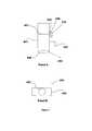
- FIG. 1provides a diagram showing the anatomy of skin.
- FIG. 2 panels A-Care schematics showing a device for generating and harvesting a plurality of micrografts.
- Panel Aprovides an exploded view of the device.
- Panel Bprovides a top view of the assembled device.
- Panel Cprovides a side view of the assembled device.
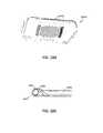
- FIG. 3 panels A-Bis a drawing showing a device of the invention for raising a suction blister.
- FIG. 4 panels A-Dshow different devices of the invention for raising a suction blister.
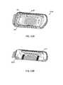
- FIG. 5 panels A-Bshow schematics of head of a device according to the invention.
- Panel Aprovides a top view of the head.
- Panel Bshows a side view of the head.
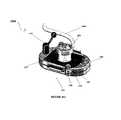
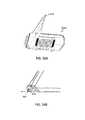
- FIG. 6provides a diagram showing an external schematic of a device with a head coupled to a hollow body.
- FIG. 7Ais a schematic depicting the components of an exemplary embodiment of a blister harvesting device according to the invention
- FIG. 7Bis a schematic depicting the components of an exemplary embodiment of a blister generation module for coupling with the blister harvesting device of FIG. 7A .
- FIGS. 8A-8Care schematics depicting the assembly procedure of the components depicted in FIGS. 7A and 7B .
- FIG. 9is a schematic depicting the components of an exemplary embodiment of a cutter assembly for use in the devices according to the invention.
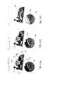
- FIG. 10Ais a schematic depicting an exemplary embodiment of a device according to the invention in a blister generation mode
- FIG. 10Bis a schematic depicting an exemplary embodiment of a device according to the invention in a blister harvesting mode.
- FIGS. 11A-11Care schematics depicting the blister generation steps using the device mode depicted in FIG. 10A .
- FIG. 12A-12Care schematics depicting the blister harvesting steps using the device mode depicted in FIG. 10B .
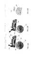
- FIG. 13is exploded schematic perspective view of another embodiment of a skin harvester according to the invention.
- FIG. 13Ais a schematic perspective view of the harvester of FIG. 13 as assembled.
- FIG. 13Bis a schematic perspective sectional view of the harvester of FIG. 13 .
- FIG. 13Cis an exploded schematic perspective view of the cutter and guide plates of the harvester of FIG. 13 .
- FIG. 13Dis a top view of the cutter and guide plates of the harvester of FIG. 13 .
- FIG. 13Eis a top view of a plate connector assembly of the harvester of FIG. 13 .
- FIG. 14Ais a perspective view of the harvester of FIG. 13 in an initial position to further illustrate the cutting mechanism.
- FIG. 14Bis sectional side view of the cutter plate drive elements of the harvester in an initial position.
- FIG. 15Ais a perspective view of the harvester of FIG. 13 in a cocked position (handle up) to further illustrate the cutting mechanism.
- FIG. 15Bis sectional side view of the cutter plate drive elements of the harvester in the cocked position.
- FIG. 16Ais a perspective view of the harvester of FIG. 13 in a mid-cut position to further illustrate the cutting mechanism.
- FIG. 16Bis sectional side view of the cutter plate drive elements of the harvester in mid-cut position.
- FIG. 17Ais a perspective view of the harvester of FIG. 13 in transitional position (from cutting to retraction) to further illustrate the cutting mechanism.
- FIG. 17Bis sectional side view of the cutter plate drive elements of the harvester in the cut-to-retract transitional position.
- FIG. 18Ais a perspective view of the harvester of FIG. 13 in a final (stroke completion) position to further illustrate the cutting mechanism.
- FIG. 18Bis sectional side view of the cutter plate drive elements of the harvester in the final (partially retracted) position.
- the present inventiongenerally relates to a single device that can raise a blister (e.g., a suction blister) and cut the raised blister, i.e., a blister raising device integrated with a cutting member.
- a blistere.g., a suction blister
- Such devicesare useful for harvesting skin grafts.
- a device as shown in FIG. 2 panels A-Cis used to raise and cut a plurality of skin grafts.
- Device 200includes a frame 201 and a lid 202 . Fitted into the frame is a bottom plate 203 , a cutter grid plate 204 , a cutter plate 205 , and a top plate 206 .
- the bottom plate 203 , the cutter plate 205 , and the top plate 206each include a hole array 211 . Once assembled, the hole array 211 of each of plates 203 , 205 , and 206 are aligned. The size of the holes in the hole array will depend on the size of the graft needed, with larger holes being used to produce larger grafts.
- a first substrate 207interacts with the top plate 206 and will receive the harvested grafts.
- Device 200further includes an actuation block 208 , actuation bar 209 , and actuation block guides 210 .
- Actuation components 208 , 209 , and 210control movement of the cutter plate 205 .
- the frame 201includes a vacuum stop 212 and the lid 202 includes a suction hole barb 213 . Once assembled, the frame 201 and lid 202 are arranged such that the vacuum stop 212 and the suction hole barb 213 are aligned with each other ( FIG. 2 panel B).
- a vacuum sourceis then connected to the device 200 such that negative pressure can be generated within the device.
- the device 200can be held together by clamp screws 214 .
- Device 200may also include a heating element.
- device 200is placed on a donor site, such as an inner thigh of a patient.
- the vacuum sourceis turned on, producing negative pressure within device 200 .
- the negative pressurecauses the skin to be pulled toward lid 202 , with a plurality of different portions of skin being pulled through each hole array 211 in each of plates 203 , 205 , and 206 .
- Such actionresults in generation of many microblisters.
- actuation components 208 , 209 , and 210are engaged to move cutter plate 205 .
- cutter plate 205disrupts the alignment of the hole arrays 211 in each of plates 203 , 205 , and 206 , and results in cutting of the microblisters.
- the cut microblistersare captured on the first substrate 207 that is above top plate 206 .
- the amount of negative pressure applied, the amount of time the vacuum is maintained, and/or the depth of the holes in plate 206determine what type of graft will be harvested, e.g., epidermal graft, split thickness graft, or full thickness graft.
- each micrograftwill have a lateral dimension of less than about 2 mm e.g., 100 to 2000 microns.
- Another aspect of the inventionprovides a device for obtaining a single skin graft.
- Such devices of the inventioninclude a hollow body having a distal end configured for placement on skin, a mechanism for raising a blister, and a cutter integrated in the body for cutting the blister produced on the skin.
- a gauge for monitoring blister formationcan be incorporated within one or more plates 203 , 205 , and 206 .
- the gaugeis preferably proximal to one or more holes of hole array 211 through which the blisters are formed.
- the gaugecan be located on the plate next to one or more holes of hole array 211 , or on an inner wall of one or more holes of hole array 211 .
- the gaugecan be configured to provide minimum indicator of a sufficient height or dimension for a blister to be cut, and/or a maximum indicator of a sufficient blister dimension to avoid excessive patient discomfort by application of the device beyond a necessary period of time.
- each hole within the hole arrayhas a depth substantially equal to the thickness of the plate.
- the gaugeis a counterbore through one or more of the holes within hole array 211 .
- the counter boreserves as a marker to indicate to the user (e.g., clinician) when the blister has reached a dimension sufficient to be cut.
- the counterborecan be approximately one-half to three-quarters of the depth of the hole as measured from the bottom or distal-most surface of the plate (i.e., the surface closest to the skin). For example, if the plate is 0.3 inches thick, the counter bore is 0.15 inches to 0.225 inches, as measured from the bottom or distal-most surface of the plate.
- the gaugecan be one or more calibration marks located proximal to or within one or more holes through which the blisters are raised.
- the calibration markscan be one or more lines having a known length that are drawn, painted or etched onto the surface of the plate proximal to one or more of the holes.
- the one or more lineshave a length of about 0.1 mm, about 0.2 mm, about 0.3 mm, about 0.4 mm, about 0.5 mm, about 1.0 mm, about 2.0 mm, about 3.0 mm, about 4.0 mm, about 5.0 mm, about 6.0 mm, about 7.0 mm, about 8.0 mm, about 9.0 mm, about 10.0 mm, about 11.0 mm, about 12.0 mm, about 13.0 mm, about 14.0 mm, about 15.0 mm, about 16.0 mm, about 17.0 mm, about 18.0 mm, about 19.0 mm, about 20.0 mm, about 21.0 mm, about 22.0 mm, about 23.0 mm, about 24.0 mm, or about 25.0 mm.
- At least two calibration markscan be drawn, painted or etched onto the surface of the plate proximal to one or more of the holes, and the distance between the at least two calibration marks can be a known length, for example about 0.1 mm, about 0.2 mm, about 0.3 mm, about 0.4 mm, about 0.5 mm, about 1.0 mm, about 2.0 mm, about 3.0 mm, about 4.0 mm, about 5.0 mm, about 6.0 mm, about 7.0 mm, about 8.0 mm, about 9.0 mm, about 10.0 mm, about 11.0 mm, about 12.0 mm, about 13.0 mm, about 14.0 mm, about 15.0 mm, about 16.0 mm, about 17.0 mm, about 18.0 mm, about 19.0 mm, about 20.0 mm, about 21.0 mm, about 22.0 mm, about 23.0 mm, about 24.0 mm, or about 25.0 mm.
- the lateral dimension of the blistercan be compared to the one or
- the calibration marksmay be one or more markings that are drawn, painted or etched onto the inner wall of one or more holes within hole array 211 of the plates. Such markings can indicate a minimum depth within the hole that is sufficient for a blister to be cut, and a maximum level for sufficient blister formation to avoid excessive patient discomfort by application of the device beyond a necessary period of time.
- a device as shown in FIG. 3 panel Ais used to obtain a skin graft.
- Device 400includes a hollow body 401 and a mechanism for raising a blister 402 .
- Hollow body 401includes a distal end 403 that is configured for placement on the skin.
- Such a distal endmay include an orifice plate 404 .
- Orifice plate 404determines the size and the shape of the blister or blisters that will be raised.
- Orifice plate 404may be any shape or size and will depend on the blister to be raised.
- the diameter or lateral dimension of the blistermay be from about 6 mm to about 12 mm, although larger or smaller blister sizes may be used.
- the mechanism for raising a blistermay be a vacuum component, a heating component, or a combination thereof.
- An exemplary heating componentis a light source.
- mechanism 402is a combination of a vacuum component and a heating component.
- the hollow body 401further includes a cutter 405 , which includes cutter plate 406 and a hole 407 ( FIG. 3 panel B).
- Device 400further includes an actuation block 408 , actuation bar 409 , and actuation block guides 410 .
- Actuation components 408 , 409 , and 410control movement of the cutter 405 .
- Blister formationis accomplished by attaching the distal end 403 of hollow body 401 to donor site of a patient, such as an inner thigh of a patient. Hook and loop fastener straps may be used to keep the device in place.
- the heating component of blister raising mechanism 402provides a slight warming of orifice plate 404 , which is in direct contact with the patient's skin surface.
- the application of a moderate negative pressure to the chamber interior from the vacuum component of blister raising mechanism 402results in the patient's skin being gently drawn through the opening in orifice plate 404 .
- the resultis a blister or blisters, approximately the size of the opening in orifice plate 404 .
- the produced blistermay be fluid-filled or may not contain any fluid, i.e., a blister having air within.
- the skin and blister areais generally not damaged and patient discomfort is minimal.
- the cutter 405is positioned in hollow body 401 such that upon raising the blister, at least a portion of the blister protrudes through hole 407 in cutter plate 406 .
- the actuation components 408 , 409 , and 410are engaged to move cutter plate 406 .
- the movement of cutter plate 406disrupts the alignment of hole 407 with the other components of device 400 , and results in cutting of the raised blister.
- the blister raising mechanism 402is capable of emitting heat ranging between about 100° C. to about 750° C. (e.g., about 500° C.). In certain aspects, the blister raising mechanism 402 emits electromagnetic radiation having a wavelength ranging between about 10 nm and about 3000 nm. In certain aspects, electromagnetic radiation emitted from blister raising mechanism 402 is reflected off one or more of the surfaces within the device, back to mechanism 402 , causing it to overheat and burnout. To prevent overheating of mechanism 402 , at least one plate of plates 203 , 205 , and 206 and/or orifice plate(s) 404 can include at least one surface configured for attenuating the reflection of electromagnetic radiation emitted from mechanism 402 . Preferably such surface is the surface facing mechanism 402 when the device is fully assembled.
- At least one surface of one or more of plate members 206 , 205 , 203 and/or orifice plate 404can be coated with a material that substantially attenuates reflection of the electromagnetic radiation (e.g., by absorbing) emitted from mechanism 402 .
- Suitable materialsinclude, for example, a thermoplastic polymer coating.
- the thermoplastic polymeris a fluoropolymer such as polytetrafluoroethylene.
- the coating materialis a dark color such as a substantially black, brown, blue or purple color.
- one or more of plate members 206 , 205 , 203 and/or orifice plate 404can be anodized, electroplated or painted a dark color such as black, brown, blue or purple to attenuate the reflection (e.g., absorb) of electromagnetic radiation emitted from mechanism 402 .
- one or more of plate members 206 , 205 , 203 and/or orifice plate 404can be abraded, scuffed, brushed, or the like, to minimize or remove a glossy or shiny surface appearance in order to attenuate reflection of electromagnetic radiation from mechanism 402 .
- FIG. 4 panel Ashows a device 500 that further includes a chamber 511 for capturing the cut blister.
- Chamber 511is positioned in hollow body 501 and above cutter 505 .
- Chamber 511may be removable from device 500 .
- Chamber 511may include multiple configurations.
- chamber 511may include a retractable bottom. The bottom is in an open position when chamber 511 is inserted into hollow body 501 . In the open position, chamber 511 is able to receive the cut blister. Once the cut blister is in chamber 511 , the bottom of the chamber is closed, capturing the blister in chamber 511 . Chamber 511 may then be removed from device 500 .
- chamber 511includes a substrate 512 ( FIG. 4 panel C).
- device 500is configured such that substrate 512 is positioned in chamber 511 so that upon raising the blister, a portion of the blister contacts the substrate and becomes attached to the substrate.
- Cutter 505then cuts the blister, and the cut blister becomes attached to the substrate 512 in chamber 511 .
- Chamber 511is then removed from device 500 , and substrate 512 may be removed from chamber 511 .
- a vacuuminstead of a substrate, is used to hold the cut blister within the chamber.
- device 500does not use a chamber, rather a substrate 512 is directly integrated with device 500 in order to capture the cut blister ( FIG. 4 , panel D). Once captured, substrate 512 having an attached cut blister may be removed from device 500 .
- the device 500includes a substrate compression mechanism for pressing the substrate against the blister to ensure that the entire blister surface contacts the substrate 512 . Full contact between the entire blister surface and the substrate ensures transfer of the blister onto the substrate when the blisters are cut.
- the compression memberis movably coupled to an exterior surface of the hollow body and actuated by an actuation member coupled to the compression member.
- the compression membercan be a plate having approximately the same size and shape as substrate 512 .
- the platecan be coupled to the hollow body via a hinged mechanism or axle member and is actuated by an extension arm or handle fixedly attached to the plate.
- the extension arm/handleis engineered to apply at least about 2 ⁇ , at least about 3 ⁇ , at least about 4 ⁇ , at least about 5 ⁇ , at least about 6 ⁇ , at least about 7 ⁇ , at least about 8 ⁇ , at least about 9 ⁇ , at least about 10 ⁇ , at least about 15 ⁇ , at least about 20 ⁇ , at least about 25 ⁇ , at least about 30 ⁇ , at least about 35 ⁇ , at least about 40 ⁇ , at least about 50 ⁇ , at least about 75 ⁇ , at least about 100 ⁇ the pressure applied to the extension arm/handle onto the plate.
- the compression mechanismcan be a cylindrical roller disposed about an actuation arm that defines a longitudinal axis. Movement of the arm in a lateral direction translates into rotational movement of the cylinder about the longitudinal axis of the arm, such that the cylinder is rolled across the surface of the substrate 512 to press the substrate against the blisters.
- the compression member and/or actuation memberare preferably reusable.
- the compression member and/or actuation memberare made of a disposable material.
- Materials for the construction of the compression plate or cylindercan be any substantially solid material such as an elemental metal, a metal alloy, a glass, a crystal, or a polymer.
- the compression member and/or actuation memberare made of titanium or stainless steel.
- the devices according to the inventioninclude a head portion that can be removably coupled with the hollow body 401 of the device.
- FIG. 5shows an exemplary embodiment of a removable head 600 that includes a blister raising mechanism 402 (e.g., a heating element) for raising a suction blister.
- the head 600includes a topmost, proximal portion 610 , and a distal portion 620 that couples with the hollow body of the device.
- the head 600is coupled to the hollow body 401 via holes 608 .
- a vacuum sourcecan be attached to suction tubing 604 to generate negative pressure within the hollow body of the device.
- FIG. 6shows head 600 coupled to hollow body 401 (collectively 700 ).
- the head deviceincludes one or more viewing windows 602 .
- the viewing windowsare located to provide optimal viewing of blister formation within the hollow body of the device.
- a plurality of viewing windows 602can be integrated within the head 600 to allow for alternative views of blister formation, or allow more than one user to monitor the development of the blisters.
- an ocular shieldcircumscribes the viewing lens such then when the user is viewing blister formation, the shield attenuates entrance of ambient light into the viewing lens.
- the viewing window 602can be made of any transparent material.
- the viewing window 602is comprised of optical quality material, for example an optical polymer, an optical glass, or an optical crystal.
- Such materialscan further include one or more of an anti-fogging material, an anti-scratch coating, or an anti-glare coating, located on either the or both the interior surface, the exterior surface, or both.
- the viewing windowis made of a heat resistant optical polymer, optical glass, or optical crystal to prevent warping or distortion from the heating element of the blister raising mechanism 402 within the head 600 .
- At least a portion of the viewing window 602can further include a magnification lens to facilitate viewing of the blisters during formation.
- the magnification power of the lenscan be at least about 2 ⁇ , at least about 3 ⁇ , at least about 4 ⁇ , at least about 5 ⁇ , at least about 6 ⁇ , at least about 7 ⁇ , at least about 8 ⁇ , at least about 9 ⁇ , at least about 10 ⁇ , at least about 15 ⁇ , at least about 20 ⁇ , at least about 25 ⁇ , at least about 30 ⁇ , at least about 35 ⁇ , at least about 40 ⁇ , at least about 50 ⁇ , at least about 75 ⁇ , at least about 100 ⁇ .
- the viewing window 602can include one or more calibration marks etched or painted on the viewing window 602 for monitoring blister formation.
- the calibration markscan be calibrated to the magnification power of the lens to approximate the actual dimensions of the forming blister, such as the actual height, the actual diameter, or both.
- the head 600can include a mechanism for raising a blister 402 .
- Such mechanismtypically includes a heating element, such as nichrome wire, and is located in the topmost, proximal portion 610 of head 600 .
- head 600includes a transparent or a translucent surface 620 forming the distal side 612 of the head 600 (i.e., distal to the heating element).
- the transparent or translucent surfaceis made of a material that facilitates the transmission of electromagnetic radiation emitted from the heating element within head 600 to one or more plate members incorporated within the hollow body, thereby warming the plate members and subsequently the skin surface.
- the transparent or translucent surfaceis made of material that allows light having a wavelength between about 10 nanometers to about 3000 nanometers to be transmitted through the surface.
- Suitable materials for transmission of light within such rangeincludes, for example, crystalline materials such as sapphire, quartz, silicon, garnet, sillenite, fused silica, fused quartz, titanium dioxide, zinc selenide, calcium fluoride, barium fluoride, zinc sulphide, caesium iodide, germanium, thallium bromo-iodide, lithium fluoride, magnesium fluoride, potassium bromide, sodium chloride, or strontium fluoride.
- the crystalline materialcan polarized.
- suitable materialsinclude glass such as silica glass, fluoride glass, aluminosilicate glass, phosphate glass, borate glass, chalcogenide glass, or polymer glass.
- the glasscan be polarized.
- the head 600includes two transparent or translucent surfaces 620 forming the distal side 612 of head 600 .
- the two plates surfacesare in a stacked configuration with an airspace in between them.
- the airspace between the transparent or translucent surfacesis about 0.1 mm, about 0.2 mm, about 0.3 mm, about 0.4 mm, about 0.5 mm, about 0.6 mm, about 0.7 mm, about 0.8 mm, about 0.9 mm, about 1.0 mm, about 2.0 mm, about 3.0 mm, about 4.0 mm, about 5.0 mm, about 6.0 mm, about 7.0 mm, about 8.0 mm, about 9.0 mm, about 10.0 mm, about 11.0 mm, about 12.0 mm, about 13.0 mm, about 14.0 mm, about 15.0 mm, about 16.0 mm, about 17.0 mm, about 18.0 mm, about 19.0 mm, about 20.0 mm, about 21.0 mm, about 22.0 mm, about 23.0 mm, about 24.0 mm
- the two transparent or translucent surfacescan be the same materials, or different materials.
- the two surfacescan both be made of a glass or crystalline material.
- one of the surfacesis a glass material, while the other surface is a crystalline material.
- the inventionrelates to an integrated device for generating micrografts and transferring micrografts. More specifically, the invention relates to a device for generating substantially planar micrografts and for preparing a surgical dressing to facilitate presentation of the micrografts to a patient in need thereof.
- the device of the inventioncan be used to prepare any type of skin graft, such as an epidermal skin graft, a split thickness graft, or a full thickness graft.
- the device of the inventionis particularly well suited for preparing skin grafts including only or substantially only the epidermal layer of skin.
- the device of the inventioncan be used for autografts, allografts, or xenografts. In preferred embodiments, the grafts are autografts.
- device 1200includes a top housing 1201 , a cutter assembly 1202 and a base housing 1203 .
- the top housingincludes a rotatable handle 1213 that is coupled to the cutter assembly 1202 .
- the top housingfurther includes a strap 1211 for coupling the device 1200 (once assembled) against a skin surface.
- the strapmay be adjustable in size, or may be a fixed size.
- the top housing 1201is configured to removably receive a blister generation module 1210 that includes a blister generation device 1204 and an adaptor plate 1205 ( FIG. 2B ).
- FIGS. 3A-3Cdepict the assembly of device 1200 .
- cutter assembly 1202is inserted into top housing 1201 .
- Top housing 1201is then coupled to base housing 1203 via one or more threaded screws 1212 that are received by a corresponding threaded holes 1218 in base housing 1203 , such that cutter assembly 1202 is disposed in between top housing 1201 and bottom housing 1203 ( FIG. 3B ).
- the blister generation module 1210is then inserted into top housing 1201 .
- the bottom of adaptor plate 1205 that interfaces with top housing 1201includes a gasket around the bottom perimeter of the plate 1205 to create an airtight seal between adaptor plate 1205 and top housing 1201 when coupled together.
- the blister generation device 1204 of the blister generation module 1210is coupled to an opening 1205 a within adaptor plate 1205 .
- a gasketis disposed within opening 1205 a to form an airtight seal between blister generation device 1204 and adaptor plate 1205 when coupled together.
- the cutter assembly 1202includes a bottom plate 1202 a , a middle plate 1202 b , and a top plate 1202 c , each of which include an array of openings 1214 (e.g., holes or slots) (sometimes referred to herein as hole array 1214 ).
- One or more openings of the hole array 1214 in the bottom 1202 a , middle 1202 b and/or top 1202 c platesdefine a cutting edge or surface 1215 .
- one or more openings in the hole array 1214 of at least the middle plate 1202 bdefine a cutting edge or surface 1215 ( FIG. 4 ).
- the three platesare assembled in a stacked configuration with the middle plate 1202 b being coupled to the bottom plate 1202 a , and the top plate 1202 c being coupled to the middle plate 1202 b .
- One or more of plates 1202 a , 1202 b and 1202 care configured to be movable in a lateral direction relative to each other.
- the middle plate 1202 bmay be laterally movable relative to the bottom plate 1202 a , the top plate 1202 c , or both.
- the top plate 1202 cmay be movable relative to the middle plate 1202 b , the bottom plate 1202 a , or both.
- the one of more of plates 1202 a , 1202 b and 1202 care configured to laterally move within a fixed distance relative to each other.
- the middle plate 1202 b and/or top plate 1202 ccan be coupled to their respective plates in the stacked configuration via at least one frangible section which serves to keep the plates in alignment until a lateral force is applied to the middle 1202 b and/or top 1202 c plate, which breaks the frangible section(s) and allows lateral movement of the plates relative to each other.
- at least the middle plate 1202 bis coupled to the bottom plate 1202 a via at least one frangible section.
- the at least one frangible sectionis configured to break when a lateral force is applied to the middle plate 1202 b , allowing the middle plate 1202 b to move in a lateral direction relative to the bottom plate 1202 a , the top plate 1202 c , or both.
- middle plate 1202 bis configured to laterally move within a fixed distance relative to the bottom plate 1202 a and/or top plate 1202 c .
- the middle plate 1202 bincludes one or more grooves or channels 1216 that are configured to receive a pin 1217 vertically extending from bottom plate 1202 a .
- Pin 1217is received at one end of channel 1216 when the frangible section is intact, and laterally slides within channel 1216 to the opposite end when the frangible section is broken, such that the lateral movement of plate 1202 b relative to plate 1202 a and/or 1202 c is fixed by the movement of pin 1217 within channel 1216 .
- One or more coupling memberscan be disposed between the plates to form the frangible sections, as described in further detail below.
- the one or more coupling membersare disposed between the openings within hole array 1214 .
- the one or more coupling membersare disposed between the plates outside of hole array 1214 .
- the frangible coupling of the plate members to each othercan be accomplished using a mechanical stamping technique, a mechanical punch technique, spot welding, photo etching, an epoxy, an adhesive, mechanical compression, a snap-fit assembly, a tongue and groove assembly, a post and bar assembly, a frangible pin, or any combination thereof.
- the middle plate 1202 b and/or top plate 1202 ccan be coupled to their respective plates in the stacked configuration via at least one elastic member or spring member which serves to keep the plates in alignment until a lateral force is applied to the middle 1202 b and/or top 1202 c plate, which allows the elastic/spring section(s) to flex and allows lateral movement of the plates relative to each other. Upon removal of the lateral force, the elastic/spring sections relax, which allows the plates to return to their original positions such that the hole arrays 1214 between the plates are once again in concentric alignment.
- the one or more elastic coupling members or spring memberscan be disposed between the openings within hole array 1214 . Alternatively, the one or more elastic coupling members or spring members can be disposed between the plates outside of hole array 1214 .
- the hole arrays 1214 of the bottom 1202 a , middle 1202 b and top 1202 c platesinclude holes that are substantially similar in size and substantially cylindrical in shape.
- the size of the holes in each hole array 1214will depend on the size of the graft needed, with larger holes being used in each plate to produce larger grafts. In certain embodiments, the holes in the hole array 1214 range between 1 mm and 12 mm in diameter, or any specific value in between.
- the diameter of the holes in the hole array 1214 of one or more of plates 1202 a , 1202 b and 1202 ccan be 1 mm, 1.5 mm, 2 mm, 2.5 mm, 3 mm, 3.5 mm, 4 mm, 4.5 mm, 5 mm, 5.5 mm, 6 mm, 6.5 mm, 7 mm, 7.5 mm, 8 mm, 8.5 mm, 9 mm, 9.5 mm, 10 mm, 10.5 mm, 11 mm, 11.5 mm or 12 mm.
- the holes in hole array 1214vary in size and/or shape between the bottom plate 1202 a , middle plate 1202 b and/or top plate 1202 c .
- holes 1202 a , 1202 b and 1202 c of cutter assembly 1202are assembled (i.e., in the stacked configuration), the hole array 1214 of each of plates 1202 a , 1202 b , and 1202 c are aligned.
- hole arrays 1214 of plates 1202 a , 1202 b , and 1202 care concentrically aligned.
- the device 1200has two modes of operation: 1) a blister generation mode ( FIG. 5A ); and 2) a blister harvesting mode ( FIG. 5B ).
- the blister generation modeincludes the assembly with the blister generation module 1210 .
- the blister generation module 1210is removed from the device assembly for blister harvesting mode ( FIG. 5B ).
- device 1200 in the blister generation modei.e., with blister generation module 1210 , as shown in FIG. 5A
- Strap 1211is used to keep the device 1200 in place against the skin surface of donor site 1220 .
- the blister generation device 1204is activated by turning/cranking handle 1204 a of blister generation device 1204 .
- the blister generation device 1204utilizes a vacuum component, a heating component, or a combination thereof, for raising skin blisters.
- An exemplary heating componentis a light source.
- mechanismis a combination of a vacuum component and a heating component.
- the blister generation device 1204is a suction blister device for suction blister grafting.
- Suction blister graftinginvolves raising a skin blister, and then cutting off the raised blister.
- An exemplary suction blister grafting techniqueis shown in Awad, (Dermatol Surg, 34(9):1186-1193, 2008), the content of which is incorporated by reference herein in its entirety.
- This articlealso shows various devices used to form suction blisters.
- a suction blister deviceis also described in Kennedy et al. (U.S. Pat. No. 6,071,247), the content of which is incorporated by reference herein in its entirety.
- An exemplary deviceis the commercially available Negative Pressure Cutaneous Suction System from Electronic Diversities (Finksburg, Md.).
- a device for raising a suction blistertypically operates by use of suction chambers that are attached to a patient's skin.
- An instrumenttypically contains a power source, a vacuum pump, temperature controls and all related controls to operate multiple suction chambers.
- the suction chambersare connected to the console by a flexible connection.
- Each of the chambersis controlled by a preset temperature control to provide an optimal skin warming temperature. Both chambers share an adjustable common vacuum source that affects all chambers equally.
- the chamber heating systemprovides a slight warming of an orifice plate of the device, which is in direct contact with the patient's skin surface.
- the negative pressure chamberis fabricated of mostly plastic components, with two removable threaded caps. The upper cap is fitted with a clear viewing lens so that the actual blister formation can be observed.
- the opposite end of the chamberis fitted with a removable orifice plate that is placed on the patient's skin. Since this plate is simply threaded onto the chamber end, multiple plates with different opening patterns can be interchanged as desired.
- the interior of the deviceis warmed and illuminated by an array of low voltage incandescent lamps.
- This lamp arrayis controlled from the instrument console temperature controller, cycling as needed, to maintain the set point temperature.
- the heat from these lampsis radiated and conducted to the orifice plate, which then warms the patient's skin.
- the chamberis connected to the console via a composite vacuum and low voltage electrical system. Quick connections are used for the vacuum and electrical system to facilitate removal and storage.
- the Negative Pressure Instrument consoleis a self-contained fan cooled unit which is designed to operate on 120 VAC 60 Hz power. Vacuum is supplied by an industrial quality diaphragm type vacuum pump, capable of a typical vacuum of 20 in Hg (0-65 kpa) at 0 CFM. An analog controller that is preset to 40° C. provides the temperature control for each suction chamber. This provides accurate control of the orifice plate temperature.
- the instrument consolehas internal adjustments that allow the user to recalibrate the temperature setting if desired. Other temperatures can be preset if desired.
- the front panelincludes a vacuum gauge and vacuum bleeder adjustment to regulate the vacuum to both chambers. The console front panel also contains the connections for the chamber assemblies.
- the application of a moderate negative pressure from the blister generation device 1204causes the patients skin to be gently drawn through the concentrically aligned hole arrays 1214 of plates 1202 a , 1202 b and 1202 c in cutter assembly 1202 ( FIG. 6B ). Such action results in generation of a plurality of raised microblisters 1221 , particularly epidermal microblisters.
- the blisters 1221may or may not be fluid-filled.
- the plurality of suction blisters 1221 generatedare of uniform size, approximately the size of the openings/holes in the hole arrays 1214 of the three plates of cutter assembly 1202 , and are uniformly spaced in accordance with the configuration of the holes in hole array 1214 , such that a plurality of substantially planar microblisters 1221 are generated.
- the skin and blister areais generally not damaged and patient discomfort is minimal.
- the deviceis converted into the blister harvesting mode by removing the blister generation module 1210 from the top housing 1201 , thereby exposing the hole array 1214 in the top plate 1202 c of cutter assembly 1202 . At least a portion of the raised microblisters 1221 protrude through the top of the hole array 1214 , as shown in FIGS. 6B and 6C .
- a substrate 1219is applied to the surface of hole array 1214 , as shown in FIGS. 5B and 7A , such that the substrate 1219 is in direct contact with the raised blisters 1221 .
- handle 1213is rotated in a clockwise or counterclockwise direction ( FIG. 7B ).
- Handle 1213is coupled to the middle plate 1202 b of cutter assembly 1202 in a configuration that translates the rotational movement of the handle 1213 into lateral movement of middle plate 1202 b .
- the lateral force applied to middle plate 1202 b by handle 1213causes middle plate 1202 b to move in a lateral direction relative to bottom plate 1202 a and/or top plate 1202 c , thereby disrupting the alignment of the hole arrays 1214 between plates 2012 a , 2012 b and 1202 c .
- the lateral displacement of the hole array 1214 of middle plate 1202 bcauses the cutting surface 1215 defined by one or more holes in the hole array 1214 to cut the raised blisters 1221 .
- the raised blisters 1221are simultaneously transferred/retained on substrate 1219 in the same configuration as generated within hole array 1214 , resulting in a substrate containing a plurality of micrografts that are uniformly spaced and oriented on the substrate 1219 (i.e., a substrate containing a plurality of substantially planar micrografts).
- device 1200integrate consumable/single-use components (e.g., substrate 1219 and/or cutter assembly 1202 ) and re-usable, sterilizable or cleaned components (e.g., top housing 1201 , base housing 1203 and blister generation module 1210 ), thereby providing a reliable system that is easy to maintain. All components of device 1200 that come into contact with the donor and/or recipient tissue (both single-use and reusable components) must be sterile/sterilized to reduce the risk of infection.
- consumable/single-use componentse.g., substrate 1219 and/or cutter assembly 1202
- re-usable, sterilizable or cleaned componentse.g., top housing 1201 , base housing 1203 and blister generation module 1210
- substrate 1219includes an adhesive on one side that facilitates attachment of the blisters to the substrate.
- the substrate materialmay have intrinsic adhesive properties, or alternatively, a side of the substrate may be treated with an adhesive material, e.g., an adhesive spray such as LEUKOSPRAY (Beiersdoerf GmbH, Germany).
- the substratemay be a deformable non-resilient material.
- a deformable non-resilient materialrefers to a material that may be manipulated, e.g., stretched or expanded, from a first configuration to a second configuration, and once in the second configuration, there is no residual stress on the substrate. Such materials may be stretched to an expanded configuration without returning to their original size.
- Such deformable non-resilient materialstend to be soft, stiff or both soft and stiff. Softness is measured on the durometer scale.
- An example of such a materialis a soft polyurethane.
- a soft polyurethaneis produced is as follows. Polyurethanes in general usually have soft and hard segments. The hard segments are due to the presence of phenyl bridges. In a soft polyurethane, the phenyl bridge is switched out for an aliphatic, which is more flexible as its 6 carbon ring has no double bonds. Therefore, all the segments are soft. On the Durometer Scale, a soft polyethylene is rated about Shore 80A.
- Other materials suitable for use with the device 1200 of the inventioninclude low density polyethylene, linear low density polyethylene, polyester copolymers, polyamide copolymers, and certain silicones.
- the substrate 1219is TegadermTM.
- the substrate containing the plurality of uniformly spaced and oriented (i.e., substantially planar) micrograftsis applied to a recipient of site of a patient.
- the sitePrior to applying the grafts to the recipient site, the site is prepared to receive the grafts using any technique known in the art. Necrotic, fibrotic or avascular tissue should be removed. The technique used to prepare the site will depend on damage to the recipient site. For example, epidermal tissue, if present at the recipient site, can be removed to prepare the area for receiving the micrografts. Burned or ulcerated sites may not need removal of epidermal tissue, although some cleaning of the site or other preparation of the site may be performed.
- Woundsshould be debrided and then allowed to granulate for several days prior to applying the graft. Most of the granulation tissue should be removed since it has a tendency to harbor bacteria. Applying silver sulfadiazine to the wound for 10 days prior to grafting reduces the bacterial count greatly.
- the size of the area at the recipient sitecan be about the same size as the area of the substrate having micrografts adhered thereto. This size generally will be greater than the area of the original graft tissue that was removed from the donor site to form the micrografts.
- the depigmented or damaged skincan be dermabraded with sandpaper or another rough material.
- the epidermal tissuecan be removed from the recipient site by forming one or more blisters over the area to be treated, e.g., a suction blister or a freezing blister, and the raised epidermal blister tissue can then be removed by cutting or another procedure.
- the substrate having the substantially planar micrograftscan be placed over the area to be treated to form a dressing.
- a portion of the substrate having the micrograftscan be positioned over the area to be repaired, e.g., the area from which the epidermal tissue has been abraded or removed for repigmentation.
- the substratecan be fixed in place over the treatment area, e.g., using tape or the like.
- the substratecan be removed after sufficient time has elapsed to allow attachment and growth of the micrografts in the treatment area, e.g., several days to a few weeks.
- the inventionfurther relates to methods for manufacturing uniform components for use in the integrated devices of the invention.
- the components within cutter assembly 1202must be substantially uniform with respect to one another.
- the planar surfaces of the components within cutter assembly 1202must be substantially uniform.
- one or more coupling membersare used to create a frangible coupling between at least two of plate members 1202 a , 1202 b and 1202 c .
- the coupling membersare disposed between two or more of the plate members to form a frangible section that is broken upon movement of said plates with respect to each other, as previously described.
- the tolerance for any inconsistencies between the planar surfaces of the coupling members and one or more of the plate members and/or inconsistent dimensions (e.g., width) between the coupling members and one or more of the plate membersis very low and could result in non-planar, non-uniform micrografts and device malfunction.
- Inconsistencies between the planar surfaces of different stocks of sheet material, manufacturing methods of blanks for the coupling members and/or plates, and finishing methods of the coupling members and/or platescan each increase tolerance stackups beyond an acceptable level, thereby decreasing the efficiency and function of device and resulting in micrografts that are unusable, and increase patient discomfort/distress.
- the plurality of coupling membersare preferably formed from the same sheet stock of material as at least one plate member in the cutter assembly 1202 .
- the plurality of coupling members and at least middle plate member 1202 b in cutter assembly 1202are preferably formed from the same sheet stock of material (e.g., a single sheet stock of material).
- Forming the coupling members and the middle plate member 1202 b from the same sheet stockensures a uniform thickness between the coupling members and between the coupling members and plate member 1202 b , and ensures uniform, planar mating surfaces between the coupling members and plate member 1202 b , thereby decreasing tolerance stackups within cutter assembly 1202 and ensuring proper device function.
- Plate members 1202 a , 1202 b , and 1202 ccan be formed from the same material, or different materials with respect to each other, so long as the materials used result in substantially planar mating surfaces between the three plates.
- plate members 1202 a , 1202 b , and 1202 care formed from a metallic material (e.g., the same metallic material, or different metallic materials).
- each of plate member 1202 a , 1202 b , and 1202 cis formed from the same sheet stock of material, preferably a single sheet stock of material.
- One or more openingsare formed within each plate member to form hole arrays 1214 that align when the plate members are assembled, as previously described.
- the coupling membersare formed from the same sheet stock from which the plurality of plate members are generated. Forming the coupling members and plate members from the same sheet stock ensures uniformity in the thickness among and between the coupling members and plate members, and uniformly planar mating surfaces between the coupling members and plate members, thereby decreasing tolerance stackups within cutter assembly 1202 and ensuring proper device function.
- the coupling memberscan be any shape or dimension sufficient to couple the plates together without obstructing the holes in the hole arrays 1214 through which the suction blisters are raised.
- the coupling memberscan be substantially square or rectangular in shape.
- the coupling membersare substantially circular in shape.
- the coupling membersare of a sufficient shape and size for location between the holes of the hole arrays 1214 of the plate members.
- the coupling membersare of a sufficient shape and size for location along the edges of the plurality of plates.
- any methodcan be used to manufacture the plates and/or coupling members, such as drilling, milling, laser etching, lithographic processing, photo etching, laser ablation and the like.
- a photo etching processis used to manufacture the plates and/or coupling members.
- the frangible coupling between the coupling members and plate memberscan be accomplished using a variety of techniques.
- the coupling memberscan be frangibly coupled between the plate members via spot welding techniques (e.g., laser spot welding), via an adhesive such as epoxy, polyurethane, acrylic or a resin, via a frangible pin, a snap-fit or tongue and groove assembly.
- frangible coupling techniquescan be accomplished using one or more manufacturing processes such as cold-heading, multiple-die forming, multiple-die progression, multiple-die headers, casting, stamping, punching, atomic hydrogen welding, bare metal arc welding, carbon arc welding, flux cored arc welding, gas metal arc welding, gas tungsten arc welding, plasma arc welding, shielded metal arc welding, submerged arc welding, air acetylene welding, oxyacetylene welding, oxygen/propane welding, oxy hydrogen welding, pressure gas welding, resistance spot welding, resistance seam welding, projection welding, flash welding, upset welding, co-extrusion welding, cold pressure welding, diffusion welding, explosion welding, electromagnetic pulse welding, forge welding, friction welding, friction stir welding, hot pressure welding, hot isostatic pressure welding, roll welding, ultrasonic welding, electron beam welding, electroslag welding, flow welding, induction welding, laser beam welding, percussion welding, thermite welding, electrogas welding, and stud arc welding.
- manufacturing processessuch as cold-head
- a portion of the plate material at or around the site of the frangible couplingis removed to accommodate at least a portion of the coupling member by forming a depression at or around the frangible section.
- laser etching or photo etching on the plate memberis used to circumscribe the coupling point at or proximal to the frangible coupling.
- a depression at or proximal to the plate membercan be removed with any method known in the art, for example drilling, milling, laser etching, photo etching, laser ablation and the like.
- FIG. 13is exploded view of another embodiment of a skin harvester according to the invention.
- Harvester 2000includes a bottom element 2002 with a strap coupler 2004 (e.g., for joining a hook and fastener-type strap to the harvester to facilitate attachment of the harvester 2000 to a patient's skin, e.g., by wrapping the device around a patient's leg for harvesting skin from the inner thigh).
- a strap coupler 2004e.g., for joining a hook and fastener-type strap to the harvester to facilitate attachment of the harvester 2000 to a patient's skin, e.g., by wrapping the device around a patient's leg for harvesting skin from the inner thigh.
- the harvester 2000also includes a cutter assembly with a bottom plate 2006 , a top plate 2008 and a middle (cutter) plate 2010 configurable to initially provide concentrically aligned holes through which blisters can be raised.
- the operation of the plates, 2006 , 2008 and 2010 of the cutter assemblyis similar to that of elements 1202 a , 1202 b and 1202 c described above in connection with FIGS. 7-12 .
- the harvester 2000further includes a cutter drive sled 2012 , handle actuator 2014 and a top element 2016 .
- FIG. 13Ais a schematic perspective view of the harvester 2000 as assembled (with top element 2016 omitted for clarity).
- FIG. 13Bis a schematic perspective sectional view of the harvester 2000 .
- FIG. 13Cis an exploded schematic perspective view of the guide and cutter plates 2006 , 2008 and 2010 of the harvester 2000 .
- the cutter plate 2010is designed to move a direction parallel to guide plates 2006 and 2008 in a one-time, back and forth motion. Following the formation of microblisters that protrude through the aligned holes, the cutter plate moves in the direction 2026 to slice the blisters and then moved in the opposite direction 2028 to at least partially retract the blade elements. The alignment of the plates is further illustrated in FIG.
- FIG. 13Dis a top view of the cutter and guide plates in a configuration where the top holes 2032 , bottom holes 2030 and cutter plate holes 2036 are aligned to permit blisters to form and pass through all three plates (The holes of the top plate can be larger than those of the bottom plate to facilitate blister formation and/or growth of the blister.)
- the cutter plate holesalso provide a cutting edge 2034 (shown in phantom) to occlude the passageway and cleave the blister when the plate 2010 is moved relative to the top and bottom guide plates 2006 , 2008 .
- FIG. 13Dfurther illustrate one of a plurality of plate connecting posts 2040 that join the top and bottom plates together and an alignment slot 2041 which allows the cutter plate to move relative to the stationary top and bottom plates 2006 , 2008 .
- the various features of the cutting platecan be formed, for example, lithographically by depositing a resist and patterning it (e.g., by expose to light) such that portions of an initial plate blank are protected from etching while other portion can be removed by etching (e.g., to form the holes and alignment slots).
- the resistcan also be patterned to provide a limited amount of protection to the cutting edge portions, thereby shaping them to have less thickness (e.g., like a knife edge).
- the sharpness of the cutting edgescan be further enhanced by electro-polishing which will reduce the overall thickness of the cutting plate.
- FIG. 13Eillustrate one way to provide a plate connector assembly.
- the vertical posts 2040can be formed by spot welding the top, bottom and cutter plates together.
- the portion of the cutter plate (“puck” 2046 ) that joins the top and bottom plates in the weldis designed to break away from the cutter plate 2010 , e.g., at the initiation of the cutting stroke.
- FIG. 14Ais a perspective view of the harvester of FIG. 13 in an initial position with the handle (actuator) 2014 in an initial position.
- the cutter plate 2010is joined to a sled 2012 as discussed above.
- the handleis linked to the sled 2012 via a generally cylindrical bar (axle) 2020 .
- the cylindrical bar 2020rotates about an axis when the handle is lifted up or closed.
- Cylindrical bar 2020also has two non-symmetric features: protrusions 2070 and 2074 .
- the handle 2014thus serves as a lever arm.
- FIG. 15Ais a perspective view of the harvester in a cocked position (handle up) to further illustrate the cutting mechanism. As shown in FIG. 15B this results in protrusion 2070 (e.g., a longitudinal ridge on the cylindrical axle) engaging with a mating feature 2072 (e.g., a groove in the sled). As the handle is brought down the sled is thus forces to move by the rotation of axle 2020 .
- FIGS. 16A and 16Billustrates the handle in a in a mid-cut position
- FIG. 17Ais a perspective view of the harvester of FIG. 13 in transitional position (from cutting to retraction) to further illustrate the cutting mechanism.
- protrusion 2070has detached from mating feature 2072 and the second protrusion 2074 has engaged with a different portion 2076 (e.g., a shoulder pad) of the sled.
- a different portion 2076e.g., a shoulder pad
- FIGS. 18A and 18Billustrate the harvester in a final (stroke completion) position.
- devices of the inventionare configured to produce epidermal grafts.
- the skinconsists of 2 layers.
- the outer layer, or epidermisis derived from ectoderm, and the thicker inner layer, or dermis, is derived from mesoderm.
- the epidermisconstitutes about 5% of the skin, and the remaining 95% is dermis.
- FIG. 1provides a diagram showing the anatomy of skin. The skin varies in thickness depending on anatomic location, gender, and age of the individual.
- the epidermisthe more external of the two layers, is a stratified squamous epithelium consisting primarily of melanocytes and keratinocytes in progressive stages of differentiation from deeper to more superficial layers.
- the epidermishas no blood vessels; thus, it must receive nutrients by diffusion from the underlying dermis through the basement membrane, which separates the 2 layers.
- the dermisis a more complex structure. It is composed of 2 layers, the more superficial papillary dermis and the deeper reticular dermis.
- the papillary dermisis thinner, including loose connective tissue that contains capillaries, elastic fibers, reticular fibers, and some collagen.
- the reticular dermisincludes a thicker layer of dense connective tissue containing larger blood vessels, closely interlaced elastic fibers, and coarse, branching collagen fibers arranged in layers parallel to the surface.
- the reticular layeralso contains fibroblasts, mast cells, nerve endings, lymphatics, and some epidermal appendages.
- Surrounding the components of the dermisis the gel-like ground substance composed of mucopolysaccharides (primarily hyaluronic acid), chondroitin sulfates, and glycoproteins.
- a substantially epidermal graft according to the inventionis more likely to adapt to the characteristics of the recipient site.
- An epidermal graftrefers to a graft that consists of substantially epidermal skin and does not include any substantial portion of the dermal layer.
- a split thickness graftrefers to a graft that includes sheets of superficial (epithelial) and some deep layers (dermal) of skin.
- a full-thickness graftrefers to a graft that includes all of the layers of the skin including blood vessels.
- Devices of the inventionmay be used to harvest a skin graft(s) for repair of numerous different types of skin damage.
- harvested graftsmay be used to treat burns (e.g., both thermal and chemical burns), blistering, dermatological conditions (e.g., epidermolysis bullosa or pyoderma gangrenosum), radiation therapy ulcers, diabetic ulcers, ischemic ulcers, trophic ulcers, trauma, or depigmentation (e.g., vitiligo).
- the skin graft(s)are used to treat vitiligo.
- Vitiligois a chronic disorder that causes depigmentation of patches of skin. It occurs when melanocytes, the cells responsible for skin pigmentation, die or are unable to function. Although patches are initially small, they often enlarge and change shape. When skin lesions occur, they are most prominent on the face, hands and wrists. Some lesions have hyper-pigmentation around the edges. Depigmentation is particularly noticeable around body orifices, such as the mouth, eyes, nostrils, genitalia and umbilicus.
- Vitiligois generally classified into two categories, non-segmental vitiligo and Segmental vitiligo.
- non-segmental vitiligoNSV
- Vitiligo where little pigmented skin remainsis referred to as vitiligo universalis.
- Non-segmental vitiligocan come about at any age, unlike segmental vitiligo which is far more prevalent in teenage years.
- Segmental vitiligodiffers in appearance, aetiology and prevalence from associated illnesses. Its treatment is different from that of non-segmental vitiligo. It tends to affect areas of skin that are associated with dorsal roots from the spine. It spreads much more rapidly than non-segmental vitiligo and, without treatment, it is much more stable/static in course and not associated with auto-immune diseases.
- an autograftis provided to the site of depigmented skin.
- the graftincludes melanocytes, and thus upon the recipient site accepting the graft, the graft will produce pigmented skin at the recipient site.
- a donor site of pigmented skinis aseptically cleaned prior to harvesting of a skin graft. Standard methods are used to clean the donor site.
- a typical donor siteis an inner thigh, but any area of pigmented skin may be used.
- a skin graftedis harvested using devices of the invention.
- Devices described hereinraise and cut a blister(s), such as a suction blister.
- the area of depigmented skini.e., the recipient site
- the graft(s)is applied to the dermabraded recipient site.
- the donor site and the recipient siteare dressed and wound care is provided.
Landscapes
- Health & Medical Sciences (AREA)
- Surgery (AREA)
- Life Sciences & Earth Sciences (AREA)
- Engineering & Computer Science (AREA)
- Heart & Thoracic Surgery (AREA)
- Veterinary Medicine (AREA)
- Nuclear Medicine, Radiotherapy & Molecular Imaging (AREA)
- Biomedical Technology (AREA)
- Public Health (AREA)
- Medical Informatics (AREA)
- Molecular Biology (AREA)
- Animal Behavior & Ethology (AREA)
- General Health & Medical Sciences (AREA)
- Plastic & Reconstructive Surgery (AREA)
- Transplantation (AREA)
- Physics & Mathematics (AREA)
- Plasma & Fusion (AREA)
- Otolaryngology (AREA)
- Surgical Instruments (AREA)
Abstract
Description
Claims (17)
Priority Applications (12)
| Application Number | Priority Date | Filing Date | Title |
|---|---|---|---|
| US13/839,518US9610093B2 (en) | 2010-08-06 | 2013-03-15 | Microblister skin grafting |
| CN201811157045.4ACN109288561B (en) | 2013-03-15 | 2014-03-14 | Microblister skin grafting |
| JP2016502380AJP6436157B2 (en) | 2013-03-15 | 2014-03-14 | Microscopic skin graft |
| CA2905978ACA2905978C (en) | 2013-03-15 | 2014-03-14 | Microblister skin grafting |
| TR2018/07063TTR201807063T4 (en) | 2013-03-15 | 2014-03-14 | Microblister skin grafting. |
| CN201480024147.2ACN105163680B8 (en) | 2013-03-15 | 2014-03-14 | microbubble skin grafting |
| EP14771124.6AEP2967641B1 (en) | 2013-03-15 | 2014-03-14 | Microblister skin grafting |
| AU2014239891AAU2014239891B2 (en) | 2013-03-15 | 2014-03-14 | Microblister skin grafting |
| PCT/US2014/027237WO2014152346A1 (en) | 2013-03-15 | 2014-03-14 | Microblister skin grafting |
| US15/439,289US10537355B2 (en) | 2010-08-06 | 2017-02-22 | Microblister skin grafting |
| JP2018202696AJP6665257B2 (en) | 2013-03-15 | 2018-10-29 | Vesicle skin transplant |
| US16/748,756US20200155187A1 (en) | 2010-08-06 | 2020-01-21 | Microblister skin grafting |
Applications Claiming Priority (8)
| Application Number | Priority Date | Filing Date | Title |
|---|---|---|---|
| US12/851,682US9597111B2 (en) | 2010-08-06 | 2010-08-06 | Methods for applying a skin graft |
| US12/851,621US8617181B2 (en) | 2010-08-06 | 2010-08-06 | Methods for preparing a skin graft |
| US12/851,656US8562626B2 (en) | 2010-08-06 | 2010-08-06 | Devices for harvesting a skin graft |
| US12/851,703US8926631B2 (en) | 2010-08-06 | 2010-08-06 | Methods for preparing a skin graft without culturing or use of biologics |
| US201161567946P | 2011-12-07 | 2011-12-07 | |
| US13/346,329US8978234B2 (en) | 2011-12-07 | 2012-01-09 | Methods of manufacturing devices for generating skin grafts |
| US13/346,318US9173674B2 (en) | 2010-08-06 | 2012-01-09 | Devices for harvesting a skin graft |
| US13/839,518US9610093B2 (en) | 2010-08-06 | 2013-03-15 | Microblister skin grafting |
Related Parent Applications (3)
| Application Number | Title | Priority Date | Filing Date |
|---|---|---|---|
| US12/851,621Continuation-In-PartUS8617181B2 (en) | 2010-08-06 | 2010-08-06 | Methods for preparing a skin graft |
| US13/346,318Continuation-In-PartUS9173674B2 (en) | 2010-08-06 | 2012-01-09 | Devices for harvesting a skin graft |
| US13/346,329Continuation-In-PartUS8978234B2 (en) | 2010-08-06 | 2012-01-09 | Methods of manufacturing devices for generating skin grafts |
Related Child Applications (1)
| Application Number | Title | Priority Date | Filing Date |
|---|---|---|---|
| US15/439,289ContinuationUS10537355B2 (en) | 2010-08-06 | 2017-02-22 | Microblister skin grafting |
Publications (2)
| Publication Number | Publication Date |
|---|---|
| US20130204273A1 US20130204273A1 (en) | 2013-08-08 |
| US9610093B2true US9610093B2 (en) | 2017-04-04 |
Family
ID=48903556
Family Applications (3)
| Application Number | Title | Priority Date | Filing Date |
|---|---|---|---|
| US13/839,518Expired - Fee RelatedUS9610093B2 (en) | 2010-08-06 | 2013-03-15 | Microblister skin grafting |
| US15/439,289Active2031-03-16US10537355B2 (en) | 2010-08-06 | 2017-02-22 | Microblister skin grafting |
| US16/748,756AbandonedUS20200155187A1 (en) | 2010-08-06 | 2020-01-21 | Microblister skin grafting |
Family Applications After (2)
| Application Number | Title | Priority Date | Filing Date |
|---|---|---|---|
| US15/439,289Active2031-03-16US10537355B2 (en) | 2010-08-06 | 2017-02-22 | Microblister skin grafting |
| US16/748,756AbandonedUS20200155187A1 (en) | 2010-08-06 | 2020-01-21 | Microblister skin grafting |
Country Status (1)
| Country | Link |
|---|---|
| US (3) | US9610093B2 (en) |
Cited By (4)
| Publication number | Priority date | Publication date | Assignee | Title |
|---|---|---|---|---|
| US20170172599A1 (en)* | 2010-08-06 | 2017-06-22 | Kci Licensing, Inc. | Microblister Skin Grafting |
| US11006974B2 (en) | 2015-11-03 | 2021-05-18 | Kci Licensing, Inc. | Devices for creating an epidermal graft sheet |
| US11344328B2 (en) | 2019-09-19 | 2022-05-31 | Tara Medical Devices, LLC | Devices, systems, and methods for epidermal tissue harvesting |
| US12133662B2 (en) | 2020-08-19 | 2024-11-05 | Timothy Chen | Skin graft harvester |
Families Citing this family (37)
| Publication number | Priority date | Publication date | Assignee | Title |
|---|---|---|---|---|
| US9451979B2 (en) | 2008-09-24 | 2016-09-27 | The General Hospital Corporation | Method and apparatus for grafting of skin tissue |
| US8900181B2 (en) | 2009-12-18 | 2014-12-02 | Srgi Holdings, Llc | Skin treatment and drug delivery device |
| US8978234B2 (en) | 2011-12-07 | 2015-03-17 | MoMelan Technologies, Inc. | Methods of manufacturing devices for generating skin grafts |
| US9173674B2 (en) | 2010-08-06 | 2015-11-03 | MoMelan Technologies, Inc. | Devices for harvesting a skin graft |
| US10219827B2 (en) | 2010-12-17 | 2019-03-05 | Srgi Holdings, Llc | Pixel array medical devices and methods |
| US10314640B2 (en) | 2010-12-17 | 2019-06-11 | Srgi Holdings, Llc | Pixel array medical devices and methods |
| US11278309B2 (en) | 2010-12-17 | 2022-03-22 | Srgi Holdings, Llc | Pixel array medical systems, devices and methods |
| US10967162B2 (en) | 2010-12-17 | 2021-04-06 | Srgi Holdings, Llc | Systems, devices and methods for fractional resection, fractional skin grafting, fractional scar reduction and fractional tattoo removal |
| US11109887B2 (en) | 2013-12-06 | 2021-09-07 | Srgi Holdings, Llc | Pixel array medical systems, devices and methods |
| US11000310B2 (en) | 2010-12-17 | 2021-05-11 | Srgi Holdings, Llc | Pixel array medical systems, devices and methods |
| US10695546B2 (en) | 2010-12-17 | 2020-06-30 | Srgi Holdings, Llc | Systems, devices and methods for fractional resection, fractional skin grafting, fractional scar reduction and fractional tattoo removal |
| US11103275B2 (en) | 2010-12-17 | 2021-08-31 | Srgi Holdings, Llc | Pixel array medical systems, devices and methods |
| US10702684B2 (en) | 2010-12-17 | 2020-07-07 | Srgi Holdings, Llc | Systems, devices and methods for fractional resection, fractional skin grafting, fractional scar reduction and fractional tattoo removal |
| US10856900B2 (en) | 2010-12-17 | 2020-12-08 | Srgi Holdings, Llc | Pixel array medical systems, devices and methods |
| US10736653B2 (en) | 2013-12-06 | 2020-08-11 | Srgi Holdings, Llc | Pixel array medical systems, devices and methods |
| EP3289988A1 (en) | 2013-03-14 | 2018-03-07 | KCI Licensing, Inc. | Absorbent substrates for harvesting skin grafts |
| TR201807063T4 (en)* | 2013-03-15 | 2018-06-21 | Kci Licensing Inc | Microblister skin grafting. |
| CA2926322C (en) | 2013-10-02 | 2022-10-18 | Srgi Holdings, Llc | Pixel array medical devices and methods |
| ES2827049T3 (en) | 2013-10-02 | 2021-05-19 | Srgi Holdings Llc | Pixel Set Medical Devices |
| US20170296214A1 (en) | 2013-12-06 | 2017-10-19 | Edward KNOWLTON | Pixel array medical systems, devices and methods |
| US11937846B2 (en) | 2013-12-06 | 2024-03-26 | Srgi Holdings Llc | Pixel array medical systems, devices and methods |
| US11229452B2 (en) | 2013-12-06 | 2022-01-25 | Srgi Holdings, Llc | Pixel array medical systems, devices and methods |
| US9814485B2 (en) | 2013-12-31 | 2017-11-14 | Kci Licensing, Inc. | Hydraulically actuated skin graft harvesting |
| WO2015103043A1 (en)* | 2013-12-31 | 2015-07-09 | Kci Licensing, Inc. | Sensor systems for skin graft harvesting |
| US10463392B2 (en) | 2013-12-31 | 2019-11-05 | Kci Licensing, Inc. | Fluid-assisted skin graft harvesting |
| WO2016033586A1 (en)* | 2014-08-29 | 2016-03-03 | Srgi Holdings, Llc | Pixel array medical devices and methods |
| JP6805157B2 (en) | 2015-02-05 | 2020-12-23 | エスアールジーアイ ホールディングス エルエルシーSrgi Holdings Llc | Pixel Array Medical Systems, Devices and Methods |
| US10912861B2 (en) | 2015-04-09 | 2021-02-09 | Kci Licensing, Inc. | Soft-tack, porous substrates for harvesting skin grafts |
| US9743949B2 (en)* | 2015-04-22 | 2017-08-29 | Medline Industries, Inc. | Two-dimensional needle array device and method of use |
| US11490952B2 (en) | 2015-08-31 | 2022-11-08 | Srgi Holdings, Llc | Pixel array medical devices and methods |
| US11980389B2 (en) | 2015-08-31 | 2024-05-14 | Srgi Holdings Llc | Handed spiral slotted scalpet array |
| US11751904B2 (en) | 2015-08-31 | 2023-09-12 | Srgi Holdings, Llc | Pixel array medical systems, devices and methods |
| US11564706B2 (en) | 2019-10-28 | 2023-01-31 | Srgi Holdings, Llc | Pixel array medical systems, devices and methods |
| US20190275177A1 (en) | 2016-11-29 | 2019-09-12 | Kci Licensing, Inc. | Identification and visualization of micrografts for monitoring epithelialization |
| WO2018209230A1 (en)* | 2017-05-12 | 2018-11-15 | Kci Usa, Inc. | Adherent, bioresorbable transplant substrate |
| WO2019147991A1 (en)* | 2018-01-26 | 2019-08-01 | Kci Licensing, Inc. | Transfer dressing for epidermal transfer and method for making same |
| WO2019148149A1 (en) | 2018-01-29 | 2019-08-01 | Kci Licensing, Inc. | Epidermal harvester with integrated mechanical stretching mechanism |
Citations (123)
| Publication number | Priority date | Publication date | Assignee | Title |
|---|---|---|---|---|
| US2379574A (en) | 1943-11-05 | 1945-07-03 | Claude R Wickard | Method of producing surgical bandages with improved elastic properties |
| US2721555A (en) | 1952-12-03 | 1955-10-25 | John A Jenney | Dermatome |
| US3054404A (en) | 1961-08-14 | 1962-09-18 | Cicero P Meek | Skin graft applicator |
| US3782387A (en)* | 1972-02-29 | 1974-01-01 | R Falabella | Apparatus and methods for obtaining and making skin grafts |
| SU772544A1 (en) | 1979-01-04 | 1980-10-23 | Тартусский Ордена Трудового Красного Знамени Государственный Университет | Dermatome |
| US4345374A (en) | 1974-01-14 | 1982-08-24 | The Gillette Company | Razor with means to adjust blade geometry |
| EP0099748A1 (en) | 1982-07-21 | 1984-02-01 | Smith and Nephew Associated Companies p.l.c. | Adhesive wound dressing |
| US4600533A (en) | 1984-12-24 | 1986-07-15 | Collagen Corporation | Collagen membranes for medical use |
| US4605010A (en) | 1984-05-17 | 1986-08-12 | Western Clinical Engineering Ltd. | Pressurizing cuff |
| US4666447A (en) | 1985-01-30 | 1987-05-19 | Mentor Corporation | Skin expansion device and method of making the same |
| US4679324A (en) | 1984-11-15 | 1987-07-14 | The Gillette Company | Safety razor blades |
| US4773418A (en) | 1982-12-22 | 1988-09-27 | Rolf Hettich | Method for manufacturing a transplant |
| US4917086A (en) | 1988-05-26 | 1990-04-17 | Snyder Laboratories, Inc. | Dermatome blade assembly |
| US5015584A (en) | 1987-10-14 | 1991-05-14 | Board Of Regents, The University Of Texas System | Epidermal graft system |
| WO1992011879A1 (en) | 1991-01-09 | 1992-07-23 | Principal Ab | Transdermal perfusion of fluids |
| US5163955A (en)* | 1991-01-24 | 1992-11-17 | Autogenics | Rapid assembly, concentric mating stent, tissue heart valve with enhanced clamping and tissue alignment |
| US5386633A (en) | 1993-12-27 | 1995-02-07 | Kanno; Yukio | Hamburger patty knife with blade attachment |
| US5433221A (en)* | 1994-10-05 | 1995-07-18 | Adair; Edwin L. | Windowed self-centering drape for surgical camera |
| US5460939A (en) | 1986-04-18 | 1995-10-24 | Advanced Tissue Sciences, Inc. | Temporary living skin replacement |
| WO1995028886A1 (en) | 1994-04-21 | 1995-11-02 | Medchem Products, Inc. | Skin stretching device |
| US5476478A (en) | 1994-04-18 | 1995-12-19 | Providence Hospital | Preoperative skin stretching apparatus and method |
| US5489304A (en) | 1994-04-19 | 1996-02-06 | Brigham & Women's Hospital | Method of skin regeneration using a collagen-glycosaminoglycan matrix and cultured epithelial autograft |
| US5496339A (en) | 1994-05-17 | 1996-03-05 | Koepnick; Russell G. | Universal automated keratectomy apparatus and method |
| WO1996018432A1 (en) | 1994-12-16 | 1996-06-20 | Gelbfish Gary A | Method and associated device for removing material from body |
| US5545222A (en) | 1991-08-12 | 1996-08-13 | Bonutti; Peter M. | Method using human tissue |
| WO1996033768A2 (en) | 1995-04-27 | 1996-10-31 | Svedman Paul | Suction blister sampling |
| US5571098A (en) | 1994-11-01 | 1996-11-05 | The General Hospital Corporation | Laser surgical devices |
| US5595570A (en) | 1994-12-06 | 1997-01-21 | S.C.M.D., Ltd. | Keratome with spring loaded adjustable plate, cutting length adjustment plate, method of cutting a corneal flap, and gauge-mounted bracket for adjusting plate on keratome head |
| WO1997020509A2 (en) | 1995-12-07 | 1997-06-12 | L.R. Surgical Instruments Ltd. | An adjustable skin mesher device and a system for using the same |
| US5686303A (en) | 1994-12-30 | 1997-11-11 | Korman; Joshua | Method of growing vertebrate skin in vitro |
| WO1998016158A1 (en) | 1996-10-15 | 1998-04-23 | Burncare Bv | Method and instruments for forming skin grafts |
| US5817115A (en) | 1995-12-04 | 1998-10-06 | Chiron Vision Corporation | Apparatus for resecting corneal tissue |
| US5914261A (en) | 1990-06-01 | 1999-06-22 | Regeneron Pharmaceuticals, Inc. | Family of MAP2 protein kinases |
| US5921980A (en) | 1997-12-03 | 1999-07-13 | University Of Kentucky Research Foundation | Laser skin graft harvesting apparatus and related method |
| US5972476A (en) | 1997-11-21 | 1999-10-26 | Means Industries, Inc. | Laminated parts and method of making same |
| US6056738A (en) | 1997-01-31 | 2000-05-02 | Transmedica International, Inc. | Interstitial fluid monitoring |
| US6071247A (en) | 1996-07-21 | 2000-06-06 | Kennedy; William R. | Skin blister biopsy apparatus and method |
| US6071267A (en) | 1998-02-06 | 2000-06-06 | Kinetic Concepts, Inc. | Medical patient fluid management interface system and method |
| US6080166A (en) | 1995-12-05 | 2000-06-27 | Mcewen; James Allen | Direct linear drive dermatome |
| US6083236A (en) | 1998-08-12 | 2000-07-04 | Feingold; Vladimir | Keratome method and apparatus |
| EP1092515A1 (en) | 1999-10-15 | 2001-04-18 | NEWMAN, Martin H. | Atomically sharp edged cutting blades and methods for making same |
| US6358260B1 (en) | 1998-04-20 | 2002-03-19 | Med-Logics, Inc. | Automatic corneal shaper with two separate drive mechanisms |
| US20020052614A1 (en) | 2000-10-16 | 2002-05-02 | Gebauer Detlev P. | Blade with amorphous cutting edge |
| US6402770B1 (en) | 1998-06-01 | 2002-06-11 | Avatar Design & Development, Inc. | Method and apparatus for placing and maintaining a percutaneous tube into a body cavity |
| US20020092529A1 (en) | 2000-06-30 | 2002-07-18 | Betty Rozier | Site guard for intravenous sites and other sensitive areas |
| US6436078B1 (en)* | 1994-12-06 | 2002-08-20 | Pal Svedman | Transdermal perfusion of fluids |
| WO2003020333A2 (en) | 2001-08-29 | 2003-03-13 | Artemis Medical, Inc. | Undamaged tissue collection assembly and method |
| WO2003039382A2 (en) | 2001-11-05 | 2003-05-15 | Medgenics, Inc. | System for processing tissue |
| US6585939B1 (en) | 1999-02-26 | 2003-07-01 | Orchid Biosciences, Inc. | Microstructures for use in biological assays and reactions |
| WO2003068120A1 (en) | 2002-01-18 | 2003-08-21 | Levin John M | Force-transmission-control system and devices employing same |
| US6612310B2 (en)* | 2000-06-22 | 2003-09-02 | Oec Medical Systems, Inc. | Windowed medical drape |
| US6623498B1 (en) | 1999-02-10 | 2003-09-23 | Sis Ltd. | Cutting instrument |
| US20030212357A1 (en) | 2002-05-10 | 2003-11-13 | Pace Edgar Alan | Method and apparatus for treating wounds with oxygen and reduced pressure |
| CN2596950Y (en) | 2003-02-24 | 2004-01-07 | 孙文红 | Epiderm extraction apparatus |
| US20040097967A1 (en) | 2000-10-27 | 2004-05-20 | Ignon Roger G. | Method for skin/surface abrasion |
| WO2004071313A2 (en) | 2003-02-10 | 2004-08-26 | Applied Tissue Technologies, Llc | Apparatus for dermal tissue harvesting |
| US20040172045A1 (en) | 2002-09-28 | 2004-09-02 | Elof Eriksson | System and method for transplantation of dermal tissue |
| WO2004075764A1 (en) | 2003-02-27 | 2004-09-10 | Applied Tissue Technologies Llc | Method and apparatus for processing dermal tissue |
| WO2004078032A2 (en) | 2003-03-03 | 2004-09-16 | Kci Licensing, Inc. | Tissue processing system |
| US20040186498A1 (en) | 2003-03-17 | 2004-09-23 | Barnes Stephen Matthew | Microkeratome blade with blade separation notch |
| US6800282B1 (en) | 1997-06-26 | 2004-10-05 | Smith & Nephew, Plc | Cell culture products |
| US20040215217A1 (en) | 2001-10-01 | 2004-10-28 | The Cleveland Clinic Foundation | Skin lesion exciser and skin-closure device therefor |
| US20040237744A1 (en) | 2003-06-02 | 2004-12-02 | Chien-Fu Lin | Photo cutting apparatus |
| WO2004105576A2 (en) | 2003-05-21 | 2004-12-09 | Kci Licensing, Inc. | Tissue harvesting device and method |
| US20050038520A1 (en) | 2003-08-11 | 2005-02-17 | Francois Binette | Method and apparatus for resurfacing an articular surface |
| US6860904B2 (en) | 1991-08-12 | 2005-03-01 | Bonutti 2003 Trust-A | Method for tissue grafting |
| US20050076921A1 (en) | 2000-06-30 | 2005-04-14 | Rozier Betty M | Site guard for intravenous sites and other sensitive areas |
| US20050101972A1 (en) | 2003-11-06 | 2005-05-12 | University Of Florida Research Foundation, Inc. | Devices and systems for separating and preparing skin |
| US20050221276A1 (en) | 2002-10-11 | 2005-10-06 | Case Western Reserve University | Sensor system |
| US20050234485A1 (en) | 2001-02-16 | 2005-10-20 | Charles Seegert | Skin grafting devices and methods |
| US20050244967A1 (en) | 2004-05-03 | 2005-11-03 | Pearlman Andrew L | Closed automated system for tissue based therapy |
| US20060079852A1 (en) | 2002-12-31 | 2006-04-13 | Bubb Stephen K | Externally-applied patient interface system and method |
| US7056327B2 (en) | 1997-10-24 | 2006-06-06 | Becton, Dickinson & Company | Keratome with suspended stabilized blade, applanator and guided engagement with keratome cutter head |
| US20060141616A1 (en) | 2004-12-28 | 2006-06-29 | Yeou-Bin Guu | Cell colonies dissecting and transplanting apparatus |
| US7078582B2 (en) | 2001-01-17 | 2006-07-18 | 3M Innovative Properties Company | Stretch removable adhesive articles and methods |
| US20060173087A1 (en) | 2003-03-12 | 2006-08-03 | Hyde Patrick D | Absorbent polymer compositions, medical articles, and methods |
| US7137979B2 (en) | 2003-05-31 | 2006-11-21 | Tyrell, Inc. | Methods and devices for the treatment of skin lesions |
| US20060271070A1 (en) | 2003-02-27 | 2006-11-30 | Elof Eriksson | Method and apparatus for processing dermal tissue |
| US20060287696A1 (en)* | 2005-06-21 | 2006-12-21 | Wright David W | Heat and light therapy treatment device and method |
| WO2007034438A2 (en) | 2005-09-26 | 2007-03-29 | Koninklijke Philips Electronics N.V. | Substance sampling and/or substance delivery via skin |
| US7207998B2 (en) | 1998-08-12 | 2007-04-24 | Biovision Ag | Intracorneal lens placement method and apparatus |
| US7208006B2 (en) | 2002-03-01 | 2007-04-24 | Wilhelm Fleischmann | Process and instrument for stretching tissue of skin |
| US7244444B2 (en) | 2004-03-31 | 2007-07-17 | Cook Incorporated | Graft material, stent graft and method |
| CN101053528A (en) | 2007-06-01 | 2007-10-17 | 张磊 | Suction nozzle capable of separating large surface of skin |
| US20070255168A1 (en) | 2006-05-01 | 2007-11-01 | Hibner John A | Grid and rotatable cube guide localization fixture for biopsy device |
| US20080146980A1 (en) | 2004-06-09 | 2008-06-19 | Benny Rousso | Portable Self-Contained Device for Enhancing Circulation |
| US20090085286A1 (en) | 2007-09-26 | 2009-04-02 | T.E. Brangs, Inc. | Mechanical ball projection game devices |
| JP2009095476A (en) | 2007-10-17 | 2009-05-07 | Alcare Co Ltd | Wound dressing and its manufacturing method |
| US7540875B2 (en) | 1998-06-01 | 2009-06-02 | Avatar Design & Development, Inc. | Surgical cutting tool with automatically retractable blade assembly |
| US20100012311A1 (en) | 2006-07-18 | 2010-01-21 | Airbus France | Heat flow device |
| WO2010014716A1 (en) | 2008-07-31 | 2010-02-04 | Clevex, Inc. | Unitary shave biopsy blade |
| WO2010036788A2 (en) | 2008-09-24 | 2010-04-01 | The General Hospital Corporation | Method and apparatus for grafting of skin tissue |
| US20100152750A1 (en) | 2006-09-14 | 2010-06-17 | Omeed Memar | Apparatus and Methods for Repairing Tissue Defects |
| US20100152651A1 (en) | 2008-10-31 | 2010-06-17 | Searete Llc, A Limited Liability Corporation Of The State Of Delaware | Frozen compositions and methods for piercing a substrate |
| US20100286635A1 (en) | 2004-04-05 | 2010-11-11 | Kci Licensing, Inc. | Wound dressing with absorption and suction capabilities support |
| US20100310823A1 (en) | 2007-10-03 | 2010-12-09 | Acell Group Limited | Composite products |
| US20110077664A1 (en) | 2009-09-28 | 2011-03-31 | Wright Medical Technology, Inc. | Device for processing dermal tissue |
| WO2011059441A1 (en) | 2009-11-13 | 2011-05-19 | Smith & Nephew, Inc. | Mesher |
| WO2011075676A2 (en) | 2009-12-18 | 2011-06-23 | Knowlton Edward W | A skin treatment and drug delivery device |
| US8002779B2 (en) | 2007-12-13 | 2011-08-23 | Zimmer Surgical, Inc. | Dermatome blade assembly |
| US20110251602A1 (en) | 2008-04-01 | 2011-10-13 | The General Hospital Corporation | Method and apparatus for tissue expansion |
| US20110282309A1 (en) | 2010-04-27 | 2011-11-17 | Smith & Nephew Plc | Wound dressing and method of use |
| US20120021186A1 (en) | 2010-06-07 | 2012-01-26 | Uwe Schneider | Seam structure and method for making a seam |
| US20120035619A1 (en) | 2010-08-06 | 2012-02-09 | MoMelan Technologies, Inc. | Methods for applying a skin graft |
| WO2012019094A2 (en) | 2010-08-06 | 2012-02-09 | MoMelan Technologies, Inc. | Methods for preparing a skin graft |
| US20120035599A1 (en) | 2010-08-06 | 2012-02-09 | MoMelan Technologies, Inc. | Devices for harvesting a skin graft |
| US20120035620A1 (en) | 2010-08-06 | 2012-02-09 | MoMelan Technologies, Inc. | Methods for preparing a skin graft without culturing or use of biologics |
| US20120041430A1 (en) | 2008-04-01 | 2012-02-16 | The General Hospital Corporation | Method and apparatus for tissue grafting |
| US20120125798A1 (en) | 2009-05-30 | 2012-05-24 | Bayer Innovation Gmbh | Product having bioresorbable carrier materials and packaging |
| US20120136323A1 (en) | 2009-08-21 | 2012-05-31 | Nathan Stasko | Wound Dressings, Methods of Using the Same and Methods of Forming the Same |
| US20120172894A1 (en) | 2010-08-06 | 2012-07-05 | MoMelan Technologies, Inc. | Devices for harvesting a skin graft |
| US20120197267A1 (en) | 2011-01-27 | 2012-08-02 | MoMelan Technologies, Inc. | Devices for generating and transferring micrografts and methods of use thereof |
| US20120201793A1 (en) | 2001-11-05 | 2012-08-09 | Bellomo Stephen F | Dermal micro-organs, methods and apparatuses for producing and using the same |
| US20120244623A1 (en) | 2008-08-20 | 2012-09-27 | Patel Gordhanbhai N | Tamper evident indicating devices |
| US20120271320A1 (en) | 2011-04-20 | 2012-10-25 | Kci Licensing, Inc. | Skin graft devices and methods |
| US20130041385A1 (en) | 2011-08-10 | 2013-02-14 | Joseph Giovannoli | Apparatus for skin reduction |
| US20130145596A1 (en) | 2011-12-07 | 2013-06-13 | MoMelan Technologies, Inc. | Methods of manufacturing devices for generating skin grafts |
| US20130158627A1 (en) | 2011-11-15 | 2013-06-20 | Neurometrix, Inc. | Apparatus and method for relieving pain using transcutaneous electrical nerve stimulation |
| US20130204273A1 (en) | 2010-08-06 | 2013-08-08 | MoMelan Technologies, Inc. | Microblister skin grafting |
| US20140277454A1 (en) | 2013-03-14 | 2014-09-18 | Kci Licensing, Inc. | Absorbent Substrates For Harvesting Skin Grafts |
| EP2837370A1 (en) | 2012-03-01 | 2015-02-18 | Alcare Co., Ltd. | Wound dressing |
| US20150127077A1 (en) | 2012-05-09 | 2015-05-07 | Medoc Advanced Medical Sysytems, Ltd. | Thermal Stimulation Probe And Method |
| US20150182241A1 (en) | 2013-12-31 | 2015-07-02 | Kci Licensing, Inc. | Fluid-assisted skin graft harvesting |
Family Cites Families (3)
| Publication number | Priority date | Publication date | Assignee | Title |
|---|---|---|---|---|
| US6626901B1 (en) | 1997-03-05 | 2003-09-30 | The Trustees Of Columbia University In The City Of New York | Electrothermal instrument for sealing and joining or cutting tissue |
| US8932233B2 (en) | 2004-05-21 | 2015-01-13 | Devicor Medical Products, Inc. | MRI biopsy device |
| US20070093802A1 (en)* | 2005-10-21 | 2007-04-26 | Danek Christopher J | Energy delivery devices and methods |
- 2013
- 2013-03-15USUS13/839,518patent/US9610093B2/ennot_activeExpired - Fee Related
- 2017
- 2017-02-22USUS15/439,289patent/US10537355B2/enactiveActive
- 2020
- 2020-01-21USUS16/748,756patent/US20200155187A1/ennot_activeAbandoned
Patent Citations (172)
| Publication number | Priority date | Publication date | Assignee | Title |
|---|---|---|---|---|
| US2379574A (en) | 1943-11-05 | 1945-07-03 | Claude R Wickard | Method of producing surgical bandages with improved elastic properties |
| US2721555A (en) | 1952-12-03 | 1955-10-25 | John A Jenney | Dermatome |
| US3054404A (en) | 1961-08-14 | 1962-09-18 | Cicero P Meek | Skin graft applicator |
| US3782387A (en)* | 1972-02-29 | 1974-01-01 | R Falabella | Apparatus and methods for obtaining and making skin grafts |
| US4345374A (en) | 1974-01-14 | 1982-08-24 | The Gillette Company | Razor with means to adjust blade geometry |
| SU772544A1 (en) | 1979-01-04 | 1980-10-23 | Тартусский Ордена Трудового Красного Знамени Государственный Университет | Dermatome |
| EP0099748A1 (en) | 1982-07-21 | 1984-02-01 | Smith and Nephew Associated Companies p.l.c. | Adhesive wound dressing |
| US4773418A (en) | 1982-12-22 | 1988-09-27 | Rolf Hettich | Method for manufacturing a transplant |
| US4605010A (en) | 1984-05-17 | 1986-08-12 | Western Clinical Engineering Ltd. | Pressurizing cuff |
| US4679324A (en) | 1984-11-15 | 1987-07-14 | The Gillette Company | Safety razor blades |
| US4600533A (en) | 1984-12-24 | 1986-07-15 | Collagen Corporation | Collagen membranes for medical use |
| US4666447A (en) | 1985-01-30 | 1987-05-19 | Mentor Corporation | Skin expansion device and method of making the same |
| US5460939A (en) | 1986-04-18 | 1995-10-24 | Advanced Tissue Sciences, Inc. | Temporary living skin replacement |
| US5015584A (en) | 1987-10-14 | 1991-05-14 | Board Of Regents, The University Of Texas System | Epidermal graft system |
| US4917086A (en) | 1988-05-26 | 1990-04-17 | Snyder Laboratories, Inc. | Dermatome blade assembly |
| US5914261A (en) | 1990-06-01 | 1999-06-22 | Regeneron Pharmaceuticals, Inc. | Family of MAP2 protein kinases |
| WO1992011879A1 (en) | 1991-01-09 | 1992-07-23 | Principal Ab | Transdermal perfusion of fluids |
| US5441490A (en) | 1991-01-09 | 1995-08-15 | Principal Ab | Transdermal perfusion of fluids |
| US5441490B1 (en) | 1991-01-09 | 1997-09-16 | Svedman Paul | Transdermal perfusion of fluids |
| US5163955A (en)* | 1991-01-24 | 1992-11-17 | Autogenics | Rapid assembly, concentric mating stent, tissue heart valve with enhanced clamping and tissue alignment |
| US5888219A (en) | 1991-08-12 | 1999-03-30 | Bonutti; Peter M. | Method of using human tissue with a tissue press and system |
| US6860904B2 (en) | 1991-08-12 | 2005-03-01 | Bonutti 2003 Trust-A | Method for tissue grafting |
| US5545222A (en) | 1991-08-12 | 1996-08-13 | Bonutti; Peter M. | Method using human tissue |
| US5386633A (en) | 1993-12-27 | 1995-02-07 | Kanno; Yukio | Hamburger patty knife with blade attachment |
| US5476478A (en) | 1994-04-18 | 1995-12-19 | Providence Hospital | Preoperative skin stretching apparatus and method |
| US5489304A (en) | 1994-04-19 | 1996-02-06 | Brigham & Women's Hospital | Method of skin regeneration using a collagen-glycosaminoglycan matrix and cultured epithelial autograft |
| WO1995028886A1 (en) | 1994-04-21 | 1995-11-02 | Medchem Products, Inc. | Skin stretching device |
| US5759193A (en) | 1994-04-21 | 1998-06-02 | Medchem Products, Inc. | Single needle skin stretching device |
| US5496339A (en) | 1994-05-17 | 1996-03-05 | Koepnick; Russell G. | Universal automated keratectomy apparatus and method |
| US5433221A (en)* | 1994-10-05 | 1995-07-18 | Adair; Edwin L. | Windowed self-centering drape for surgical camera |
| US5571098A (en) | 1994-11-01 | 1996-11-05 | The General Hospital Corporation | Laser surgical devices |
| US5595570A (en) | 1994-12-06 | 1997-01-21 | S.C.M.D., Ltd. | Keratome with spring loaded adjustable plate, cutting length adjustment plate, method of cutting a corneal flap, and gauge-mounted bracket for adjusting plate on keratome head |
| US6436078B1 (en)* | 1994-12-06 | 2002-08-20 | Pal Svedman | Transdermal perfusion of fluids |
| WO1996018432A1 (en) | 1994-12-16 | 1996-06-20 | Gelbfish Gary A | Method and associated device for removing material from body |
| US5730717A (en) | 1994-12-16 | 1998-03-24 | Gelbfish; Gary A. | Method and associated device for removing material from body |
| US5914264A (en) | 1994-12-30 | 1999-06-22 | Reconstructive Technologies | Apparatus for growing vertebrate skin in vitro |
| US5686303A (en) | 1994-12-30 | 1997-11-11 | Korman; Joshua | Method of growing vertebrate skin in vitro |
| US6254580B1 (en) | 1995-04-27 | 2001-07-03 | Pal Svedman | Suction blister sampling |
| WO1996033768A2 (en) | 1995-04-27 | 1996-10-31 | Svedman Paul | Suction blister sampling |
| US5976163A (en) | 1995-12-04 | 1999-11-02 | Bausch & Lomb Surgical, Inc. | Apparatus for resecting corneal tissue |
| US5817115A (en) | 1995-12-04 | 1998-10-06 | Chiron Vision Corporation | Apparatus for resecting corneal tissue |
| US6080166A (en) | 1995-12-05 | 2000-06-27 | Mcewen; James Allen | Direct linear drive dermatome |
| US6063094A (en) | 1995-12-07 | 2000-05-16 | L.R. Surgical Instruments Ltd. | Adjustable skin mesher device and a system for using the same |
| WO1997020509A2 (en) | 1995-12-07 | 1997-06-12 | L.R. Surgical Instruments Ltd. | An adjustable skin mesher device and a system for using the same |
| US6071247A (en) | 1996-07-21 | 2000-06-06 | Kennedy; William R. | Skin blister biopsy apparatus and method |
| US6364908B1 (en) | 1996-10-15 | 2002-04-02 | Burncare B.V. | Method and instruments for stretching skin grafts |
| US6248114B1 (en) | 1996-10-15 | 2001-06-19 | Burncare B. V. | Method for forming skin grafts |
| WO1998016158A1 (en) | 1996-10-15 | 1998-04-23 | Burncare Bv | Method and instruments for forming skin grafts |
| US20010029380A1 (en) | 1996-10-15 | 2001-10-11 | Ysebaert Willem Marie | Cutting table for forming skin grafts |
| US6056738A (en) | 1997-01-31 | 2000-05-02 | Transmedica International, Inc. | Interstitial fluid monitoring |
| US6800282B1 (en) | 1997-06-26 | 2004-10-05 | Smith & Nephew, Plc | Cell culture products |
| US7056327B2 (en) | 1997-10-24 | 2006-06-06 | Becton, Dickinson & Company | Keratome with suspended stabilized blade, applanator and guided engagement with keratome cutter head |
| US5972476A (en) | 1997-11-21 | 1999-10-26 | Means Industries, Inc. | Laminated parts and method of making same |
| US5921980A (en) | 1997-12-03 | 1999-07-13 | University Of Kentucky Research Foundation | Laser skin graft harvesting apparatus and related method |
| US6071267A (en) | 1998-02-06 | 2000-06-06 | Kinetic Concepts, Inc. | Medical patient fluid management interface system and method |
| US6358260B1 (en) | 1998-04-20 | 2002-03-19 | Med-Logics, Inc. | Automatic corneal shaper with two separate drive mechanisms |
| US6402770B1 (en) | 1998-06-01 | 2002-06-11 | Avatar Design & Development, Inc. | Method and apparatus for placing and maintaining a percutaneous tube into a body cavity |
| US20030009185A1 (en) | 1998-06-01 | 2003-01-09 | Jessen John W. | Method and apparatus for placing and maintaining a percutaneous tube into a body cavity |
| US7540875B2 (en) | 1998-06-01 | 2009-06-02 | Avatar Design & Development, Inc. | Surgical cutting tool with automatically retractable blade assembly |
| US7207998B2 (en) | 1998-08-12 | 2007-04-24 | Biovision Ag | Intracorneal lens placement method and apparatus |
| US6083236A (en) | 1998-08-12 | 2000-07-04 | Feingold; Vladimir | Keratome method and apparatus |
| US6623498B1 (en) | 1999-02-10 | 2003-09-23 | Sis Ltd. | Cutting instrument |
| EP1614404A2 (en) | 1999-02-10 | 2006-01-11 | SIS AG, Surgical Instrument Systems | Blade assembly |
| US6585939B1 (en) | 1999-02-26 | 2003-07-01 | Orchid Biosciences, Inc. | Microstructures for use in biological assays and reactions |
| EP1092515A1 (en) | 1999-10-15 | 2001-04-18 | NEWMAN, Martin H. | Atomically sharp edged cutting blades and methods for making same |
| US6612310B2 (en)* | 2000-06-22 | 2003-09-02 | Oec Medical Systems, Inc. | Windowed medical drape |
| US20020092529A1 (en) | 2000-06-30 | 2002-07-18 | Betty Rozier | Site guard for intravenous sites and other sensitive areas |
| US20050076921A1 (en) | 2000-06-30 | 2005-04-14 | Rozier Betty M | Site guard for intravenous sites and other sensitive areas |
| US20020052614A1 (en) | 2000-10-16 | 2002-05-02 | Gebauer Detlev P. | Blade with amorphous cutting edge |
| US20040097967A1 (en) | 2000-10-27 | 2004-05-20 | Ignon Roger G. | Method for skin/surface abrasion |
| US7078582B2 (en) | 2001-01-17 | 2006-07-18 | 3M Innovative Properties Company | Stretch removable adhesive articles and methods |
| US20050234485A1 (en) | 2001-02-16 | 2005-10-20 | Charles Seegert | Skin grafting devices and methods |
| US7666192B2 (en) | 2001-02-16 | 2010-02-23 | Kci Licensing, Inc. | Skin grafting devices and methods |
| US20100121311A1 (en) | 2001-02-16 | 2010-05-13 | Kci Licensing, Inc. | Skin Grafting Devices and Methods |
| WO2003020333A2 (en) | 2001-08-29 | 2003-03-13 | Artemis Medical, Inc. | Undamaged tissue collection assembly and method |
| US7513902B2 (en) | 2001-10-01 | 2009-04-07 | The Cleveland Clinic Foundation | Skin lesion exciser and skin-closure device therefor |
| US20040215217A1 (en) | 2001-10-01 | 2004-10-28 | The Cleveland Clinic Foundation | Skin lesion exciser and skin-closure device therefor |
| US20120201793A1 (en) | 2001-11-05 | 2012-08-09 | Bellomo Stephen F | Dermal micro-organs, methods and apparatuses for producing and using the same |
| WO2003049783A2 (en) | 2001-11-05 | 2003-06-19 | Medgenics, Inc. | Device and methods for harvesting tissue samples of known geometry |
| WO2003049626A1 (en) | 2001-11-05 | 2003-06-19 | Medgenics, Inc. | Method and apparatus for production of a skin graft and the graft produced thereby |
| WO2003039382A2 (en) | 2001-11-05 | 2003-05-15 | Medgenics, Inc. | System for processing tissue |
| US20070183974A1 (en) | 2001-11-05 | 2007-08-09 | Pearlman Andrew L | Method and apparatus for production of a skin graft and the graft produced thereby |
| WO2003068120A1 (en) | 2002-01-18 | 2003-08-21 | Levin John M | Force-transmission-control system and devices employing same |
| US7208006B2 (en) | 2002-03-01 | 2007-04-24 | Wilhelm Fleischmann | Process and instrument for stretching tissue of skin |
| US20030212357A1 (en) | 2002-05-10 | 2003-11-13 | Pace Edgar Alan | Method and apparatus for treating wounds with oxygen and reduced pressure |
| US20100145360A1 (en) | 2002-09-28 | 2010-06-10 | Kci Licensing, Inc. | System and method for transplantation of dermal tissue |
| US7666134B2 (en) | 2002-09-28 | 2010-02-23 | Kci Licensing, Inc. | System and method for transplantation of dermal tissue |
| US20040172045A1 (en) | 2002-09-28 | 2004-09-02 | Elof Eriksson | System and method for transplantation of dermal tissue |
| US20050221276A1 (en) | 2002-10-11 | 2005-10-06 | Case Western Reserve University | Sensor system |
| US20120201755A1 (en) | 2002-10-11 | 2012-08-09 | George Rozakis | Sensor system |
| US20060079852A1 (en) | 2002-12-31 | 2006-04-13 | Bubb Stephen K | Externally-applied patient interface system and method |
| WO2004071313A2 (en) | 2003-02-10 | 2004-08-26 | Applied Tissue Technologies, Llc | Apparatus for dermal tissue harvesting |
| US20040225309A1 (en) | 2003-02-10 | 2004-11-11 | Elof Eriksson | Apparatus and method for dermal tissue harvesting |
| CN2596950Y (en) | 2003-02-24 | 2004-01-07 | 孙文红 | Epiderm extraction apparatus |
| US20040230215A1 (en) | 2003-02-27 | 2004-11-18 | Elof Eriksson | Method and apparatus for processing dermal tissue |
| US8187285B2 (en) | 2003-02-27 | 2012-05-29 | Applied Tissue Technologies Llc | Method and apparatus for processing dermal tissue |
| US7625384B2 (en) | 2003-02-27 | 2009-12-01 | Wright Medical Technology, Inc. | Method and apparatus for processing dermal tissue |
| US20100042127A1 (en) | 2003-02-27 | 2010-02-18 | Wright Medical Technology, Inc. | Method and apparatus for processing dermal tissue |
| US20060271070A1 (en) | 2003-02-27 | 2006-11-30 | Elof Eriksson | Method and apparatus for processing dermal tissue |
| WO2004075764A1 (en) | 2003-02-27 | 2004-09-10 | Applied Tissue Technologies Llc | Method and apparatus for processing dermal tissue |
| US7708746B2 (en) | 2003-02-27 | 2010-05-04 | Wright Medical Technology, Inc. | Method and apparatus for processing dermal tissue |
| US7926401B2 (en) | 2003-03-03 | 2011-04-19 | Kci Licensing, Inc. | Tissue harvesting device and method |
| US7651507B2 (en) | 2003-03-03 | 2010-01-26 | Kci Licensing, Inc. | Tissue processing system |
| US8109187B2 (en) | 2003-03-03 | 2012-02-07 | Kci Licensing, Inc. | Tissue harvesting device and method |
| WO2004078032A2 (en) | 2003-03-03 | 2004-09-16 | Kci Licensing, Inc. | Tissue processing system |
| US8162957B2 (en) | 2003-03-03 | 2012-04-24 | Kci Licensing, Inc. | Tissue processing system |
| US20060173087A1 (en) | 2003-03-12 | 2006-08-03 | Hyde Patrick D | Absorbent polymer compositions, medical articles, and methods |
| US20040186498A1 (en) | 2003-03-17 | 2004-09-23 | Barnes Stephen Matthew | Microkeratome blade with blade separation notch |
| WO2004105576A2 (en) | 2003-05-21 | 2004-12-09 | Kci Licensing, Inc. | Tissue harvesting device and method |
| US7137979B2 (en) | 2003-05-31 | 2006-11-21 | Tyrell, Inc. | Methods and devices for the treatment of skin lesions |
| US20040237744A1 (en) | 2003-06-02 | 2004-12-02 | Chien-Fu Lin | Photo cutting apparatus |
| US20050038520A1 (en) | 2003-08-11 | 2005-02-17 | Francois Binette | Method and apparatus for resurfacing an articular surface |
| WO2005033273A2 (en) | 2003-09-29 | 2005-04-14 | Kci Licensing, Inc. | System for transplantation of dermal tissue |
| US20050101972A1 (en) | 2003-11-06 | 2005-05-12 | University Of Florida Research Foundation, Inc. | Devices and systems for separating and preparing skin |
| WO2005046428A2 (en) | 2003-11-06 | 2005-05-26 | University Of Florida Research Foundation, Inc. | Devices and systems for separating and preparing skin |
| US7244444B2 (en) | 2004-03-31 | 2007-07-17 | Cook Incorporated | Graft material, stent graft and method |
| US20100286635A1 (en) | 2004-04-05 | 2010-11-11 | Kci Licensing, Inc. | Wound dressing with absorption and suction capabilities support |
| US20050244967A1 (en) | 2004-05-03 | 2005-11-03 | Pearlman Andrew L | Closed automated system for tissue based therapy |
| US20080146980A1 (en) | 2004-06-09 | 2008-06-19 | Benny Rousso | Portable Self-Contained Device for Enhancing Circulation |
| US20060141616A1 (en) | 2004-12-28 | 2006-06-29 | Yeou-Bin Guu | Cell colonies dissecting and transplanting apparatus |
| US20060287696A1 (en)* | 2005-06-21 | 2006-12-21 | Wright David W | Heat and light therapy treatment device and method |
| WO2007034438A2 (en) | 2005-09-26 | 2007-03-29 | Koninklijke Philips Electronics N.V. | Substance sampling and/or substance delivery via skin |
| WO2007117488A2 (en) | 2006-04-05 | 2007-10-18 | Applied Tissue Technologies, Llc | Method and apparatus for processing dermal tissue |
| US20070255168A1 (en) | 2006-05-01 | 2007-11-01 | Hibner John A | Grid and rotatable cube guide localization fixture for biopsy device |
| US20100012311A1 (en) | 2006-07-18 | 2010-01-21 | Airbus France | Heat flow device |
| US20100152750A1 (en) | 2006-09-14 | 2010-06-17 | Omeed Memar | Apparatus and Methods for Repairing Tissue Defects |
| CN101053528A (en) | 2007-06-01 | 2007-10-17 | 张磊 | Suction nozzle capable of separating large surface of skin |
| US20090085286A1 (en) | 2007-09-26 | 2009-04-02 | T.E. Brangs, Inc. | Mechanical ball projection game devices |
| US20100310823A1 (en) | 2007-10-03 | 2010-12-09 | Acell Group Limited | Composite products |
| JP2009095476A (en) | 2007-10-17 | 2009-05-07 | Alcare Co Ltd | Wound dressing and its manufacturing method |
| US8002779B2 (en) | 2007-12-13 | 2011-08-23 | Zimmer Surgical, Inc. | Dermatome blade assembly |
| US20120041430A1 (en) | 2008-04-01 | 2012-02-16 | The General Hospital Corporation | Method and apparatus for tissue grafting |
| US20110251602A1 (en) | 2008-04-01 | 2011-10-13 | The General Hospital Corporation | Method and apparatus for tissue expansion |
| WO2010014716A1 (en) | 2008-07-31 | 2010-02-04 | Clevex, Inc. | Unitary shave biopsy blade |
| US20120244623A1 (en) | 2008-08-20 | 2012-09-27 | Patel Gordhanbhai N | Tamper evident indicating devices |
| US20110264115A1 (en) | 2008-09-24 | 2011-10-27 | The General Hospital Corporation | Method and apparatus for grafting of skin tissue |
| WO2010036788A2 (en) | 2008-09-24 | 2010-04-01 | The General Hospital Corporation | Method and apparatus for grafting of skin tissue |
| US20100152651A1 (en) | 2008-10-31 | 2010-06-17 | Searete Llc, A Limited Liability Corporation Of The State Of Delaware | Frozen compositions and methods for piercing a substrate |
| US20120125798A1 (en) | 2009-05-30 | 2012-05-24 | Bayer Innovation Gmbh | Product having bioresorbable carrier materials and packaging |
| US20120136323A1 (en) | 2009-08-21 | 2012-05-31 | Nathan Stasko | Wound Dressings, Methods of Using the Same and Methods of Forming the Same |
| US20110077664A1 (en) | 2009-09-28 | 2011-03-31 | Wright Medical Technology, Inc. | Device for processing dermal tissue |
| WO2011038326A1 (en) | 2009-09-28 | 2011-03-31 | Wright Medical Technology, Inc. | Device for processing dermal tissue |
| WO2011059441A1 (en) | 2009-11-13 | 2011-05-19 | Smith & Nephew, Inc. | Mesher |
| WO2011075676A2 (en) | 2009-12-18 | 2011-06-23 | Knowlton Edward W | A skin treatment and drug delivery device |
| US20110282309A1 (en) | 2010-04-27 | 2011-11-17 | Smith & Nephew Plc | Wound dressing and method of use |
| US20120021186A1 (en) | 2010-06-07 | 2012-01-26 | Uwe Schneider | Seam structure and method for making a seam |
| US20120035619A1 (en) | 2010-08-06 | 2012-02-09 | MoMelan Technologies, Inc. | Methods for applying a skin graft |
| US20120035618A1 (en) | 2010-08-06 | 2012-02-09 | MoMelan Technologies, Inc. | Methods for preparing a skin graft |
| WO2012019095A2 (en) | 2010-08-06 | 2012-02-09 | MoMelan Technologies, Inc. | Devices for harvesting a skin graft |
| US20120035599A1 (en) | 2010-08-06 | 2012-02-09 | MoMelan Technologies, Inc. | Devices for harvesting a skin graft |
| WO2012019096A1 (en) | 2010-08-06 | 2012-02-09 | MoMelan Technologies, Inc. | Methods for applying a skin graft |
| US20120172894A1 (en) | 2010-08-06 | 2012-07-05 | MoMelan Technologies, Inc. | Devices for harvesting a skin graft |
| US8562626B2 (en) | 2010-08-06 | 2013-10-22 | MoMelan Technologies, Inc. | Devices for harvesting a skin graft |
| US20130204273A1 (en) | 2010-08-06 | 2013-08-08 | MoMelan Technologies, Inc. | Microblister skin grafting |
| WO2012019098A1 (en) | 2010-08-06 | 2012-02-09 | MoMelan Technologies, Inc. | Methods for preparing a skin graft without culturing or use of biologics |
| US8617181B2 (en) | 2010-08-06 | 2013-12-31 | MoMelan Technologies, Inc. | Methods for preparing a skin graft |
| US20120035620A1 (en) | 2010-08-06 | 2012-02-09 | MoMelan Technologies, Inc. | Methods for preparing a skin graft without culturing or use of biologics |
| US8926631B2 (en) | 2010-08-06 | 2015-01-06 | MoMelan Technologies, Inc. | Methods for preparing a skin graft without culturing or use of biologics |
| US9173674B2 (en) | 2010-08-06 | 2015-11-03 | MoMelan Technologies, Inc. | Devices for harvesting a skin graft |
| WO2012019094A2 (en) | 2010-08-06 | 2012-02-09 | MoMelan Technologies, Inc. | Methods for preparing a skin graft |
| WO2012102812A1 (en) | 2011-01-27 | 2012-08-02 | MoMelan Technologies, Inc. | Device for generating and transferring micrografts and methods of use thereof |
| US20120197267A1 (en) | 2011-01-27 | 2012-08-02 | MoMelan Technologies, Inc. | Devices for generating and transferring micrografts and methods of use thereof |
| WO2012145504A1 (en) | 2011-04-20 | 2012-10-26 | Kci Licensing, Inc. | Skin graft devices and methods |
| US20120271320A1 (en) | 2011-04-20 | 2012-10-25 | Kci Licensing, Inc. | Skin graft devices and methods |
| US20130041385A1 (en) | 2011-08-10 | 2013-02-14 | Joseph Giovannoli | Apparatus for skin reduction |
| US20130158627A1 (en) | 2011-11-15 | 2013-06-20 | Neurometrix, Inc. | Apparatus and method for relieving pain using transcutaneous electrical nerve stimulation |
| US20130145596A1 (en) | 2011-12-07 | 2013-06-13 | MoMelan Technologies, Inc. | Methods of manufacturing devices for generating skin grafts |
| EP2837370A1 (en) | 2012-03-01 | 2015-02-18 | Alcare Co., Ltd. | Wound dressing |
| US20150127077A1 (en) | 2012-05-09 | 2015-05-07 | Medoc Advanced Medical Sysytems, Ltd. | Thermal Stimulation Probe And Method |
| US20140277454A1 (en) | 2013-03-14 | 2014-09-18 | Kci Licensing, Inc. | Absorbent Substrates For Harvesting Skin Grafts |
| WO2014152319A2 (en) | 2013-03-14 | 2014-09-25 | Kci Licensing, Inc. | Absorbent substrates for harvesting skin grafts |
| US20150182241A1 (en) | 2013-12-31 | 2015-07-02 | Kci Licensing, Inc. | Fluid-assisted skin graft harvesting |
Non-Patent Citations (21)
| Title |
|---|
| [No Author Listed] BBC—GCSE Bitsize: Gore-Tex, Article: http://www.bbc.co.uk/schools/gcsebitesize/science/ocr—gateway—pre—2011/carbon—chem/6—designer—polyers3.shtml; retrieved Apr. 22, 2015. |
| Awad, Chinese Cupping: A Simple Method to Obtain Epithelial Grafts for the Management of Resistant Localized Vitiligo, American Society of Dermatologic Surgery, Inc., Dermatol Surg, (2008), 34(9):1186-1193. |
| Balaji et al., Isolation of a Novel Population of Multipotent Stem Cells From Epidermal Layer of Human Skin, Biology and Medicine, (2010), 2(2):57-67. |
| European Search Report mailed Apr. 17, 2015 received in European Application No. 12855127.2, 3 pages. |
| Extended European Search Report mailed Mar. 3, 2016 received in European Application No. 14771124.6, 7 pages. |
| International Search Report and Written Opinion dated Aug. 1, 2014 for International Application No. PCT/US2014/027237, 12 pages. |
| International Search Report and Written Opinion dated Dec. 16, 2011 for PCT/US11/46737. |
| International Search Report and Written Opinion dated Dec. 16, 2011 for PCT/US11/46738. |
| International Search Report and Written Opinion dated Dec. 23, 2011 for PCT/US11/46739. |
| International Search Report and Written Opinion dated Dec. 6, 2011 for PCT/US11/46741. |
| International Search Report and Written Opinion dated Feb. 15, 2013 for International Application No. PCT/US2012/068551, 9 pages. |
| International Search Report and Written Opinion dated Mar. 19, 2015 for PCT/US2014/072170, 12 pages. |
| International Search Report and Written Opinion dated Mar. 19, 2015 for PCT/US2014/072188, 12 pages. |
| International Search Report and Written Opinion dated Mar. 20, 2015 for PCT/US2014/072180, 10 pages. |
| International Search Report and Written Opinion dated Oct. 2, 2014 for International Application No. PCT/US2014/027205, 19 pages. |
| Kreis et al., Expansion techniques for skin grafts: comparison between mesh and Meek Island (sandwich-) grafts, Burns, (1994), 20(1):S39-S42. |
| Lari et al., Expansion technique for skins grafts (Meek technique) in the treatment of severely burned patients, Burns, (2001), 27:61-66. |
| Meek et al., Successful Microdermagrafting Using the Meek-Wall Microdermatome, Am J Surg, (1958), 96(4):557-558. |
| Mulekar et al., Treatment of Vitiligo on Difficult-to-Treat Sites Using Autologous Noncultured Cellular Grafting, Dermatol Surg., (2009), 25(1):66-71. |
| Sams et al.. Useful adjuncts to harvest split-thickness skin grafts. Dermatol Surg. Dec. 2004;30(12 Pt 2):1591-2. |
| Weyandt et al., Split-skin grafting from the scalp: the hidden advantage. Dermatol Surg. Dec. 2009;35(12):1873-9. |
Cited By (5)
| Publication number | Priority date | Publication date | Assignee | Title |
|---|---|---|---|---|
| US20170172599A1 (en)* | 2010-08-06 | 2017-06-22 | Kci Licensing, Inc. | Microblister Skin Grafting |
| US10537355B2 (en)* | 2010-08-06 | 2020-01-21 | Kci Licensing, Inc. | Microblister skin grafting |
| US11006974B2 (en) | 2015-11-03 | 2021-05-18 | Kci Licensing, Inc. | Devices for creating an epidermal graft sheet |
| US11344328B2 (en) | 2019-09-19 | 2022-05-31 | Tara Medical Devices, LLC | Devices, systems, and methods for epidermal tissue harvesting |
| US12133662B2 (en) | 2020-08-19 | 2024-11-05 | Timothy Chen | Skin graft harvester |
Also Published As
| Publication number | Publication date |
|---|---|
| US10537355B2 (en) | 2020-01-21 |
| US20200155187A1 (en) | 2020-05-21 |
| US20130204273A1 (en) | 2013-08-08 |
| US20170172599A1 (en) | 2017-06-22 |
Similar Documents
| Publication | Publication Date | Title |
|---|---|---|
| US10537355B2 (en) | Microblister skin grafting | |
| AU2017279616B2 (en) | Methods of manufacturing devices for generating skin grafts | |
| JP6665257B2 (en) | Vesicle skin transplant | |
| US9173674B2 (en) | Devices for harvesting a skin graft | |
| CA2807415C (en) | Devices for harvesting a skin graft | |
| US10603072B2 (en) | Methods for preparing a skin graft without culturing or use of biologics | |
| US11083487B2 (en) | Methods for preparing a skin graft | |
| KR20010013218A (en) | Surgical microtomes | |
| JP2002507135A (en) | Transmission system and method for surgical laser | |
| KR20200123265A (en) | Methods and devices for thermal tissue vaporization and compression | |
| US20210038245A1 (en) | Epidermal harvester with integrated mechanical stretching mechanism | |
| Strong | Laser surgery in Otolaryngology |
Legal Events
| Date | Code | Title | Description |
|---|---|---|---|
| AS | Assignment | Owner name:MOMELAN TECHNOLOGIES, INC., MASSACHUSETTS Free format text:ASSIGNMENT OF ASSIGNORS INTEREST;ASSIGNORS:SABIR, SAMEER AHMED;ZIEGLER, ANDREW;SIGNING DATES FROM 20150424 TO 20160804;REEL/FRAME:039357/0803 | |
| AS | Assignment | Owner name:KCI LICENSING, INC., TEXAS Free format text:ASSIGNMENT OF ASSIGNORS INTEREST;ASSIGNOR:KCI HOLDING COMPANY, INC.;REEL/FRAME:039587/0991 Effective date:20151231 Owner name:KINETIC CONCEPTS, INC., TEXAS Free format text:MERGER AND CHANGE OF NAME;ASSIGNORS:MOMELAN TECHNOLOGIES, INC;KINETIC CONCEPTS, INC.;REEL/FRAME:039587/0832 Effective date:20151222 Owner name:KCI HOLDING COMPANY, INC., TEXAS Free format text:ASSIGNMENT OF ASSIGNORS INTEREST;ASSIGNOR:KINETIC CONCEPTS, INC.;REEL/FRAME:039587/0927 Effective date:20151231 | |
| AS | Assignment | Owner name:WILMINGTON TRUST, NATIONAL ASSOCIATION, AS COLLATERAL AGENT, MINNESOTA Free format text:SECOND LIEN SECURITY AGREEMENT;ASSIGNORS:KCI USA, INC.;LIFECELL CORPORATION;KCI LICENSING, INC.;REEL/FRAME:040098/0268 Effective date:20160920 Owner name:WILMINGTON TRUST, NATIONAL ASSOCIATION, AS COLLATE Free format text:SECOND LIEN SECURITY AGREEMENT;ASSIGNORS:KCI USA, INC.;LIFECELL CORPORATION;KCI LICENSING, INC.;REEL/FRAME:040098/0268 Effective date:20160920 | |
| AS | Assignment | Owner name:WILMINGTON TRUST, NATIONAL ASSOCIATION, AS COLLATERAL AGENT, MINNESOTA Free format text:LIMITED THIRD LIEN INTELLECTUAL PROPERTY SECURITY AGREEMENT;ASSIGNORS:KCI USA, INC.;LIFECELL CORPORATION;KCI LICENSING, INC.;REEL/FRAME:040291/0237 Effective date:20161006 Owner name:WILMINGTON TRUST, NATIONAL ASSOCIATION, AS COLLATE Free format text:LIMITED THIRD LIEN INTELLECTUAL PROPERTY SECURITY AGREEMENT;ASSIGNORS:KCI USA, INC.;LIFECELL CORPORATION;KCI LICENSING, INC.;REEL/FRAME:040291/0237 Effective date:20161006 | |
| AS | Assignment | Owner name:KCI USA, INC., TEXAS Free format text:RELEASE OF SECURITY INTEREST REEL/FRAME 040098/0268;ASSIGNOR:WILMINGTON TRUST;REEL/FRAME:041666/0320 Effective date:20170203 | |
| STCF | Information on status: patent grant | Free format text:PATENTED CASE | |
| AS | Assignment | Owner name:KCI USA, INC., TEXAS Free format text:RELEASE OF SECURITY INTEREST IN PATENTS;ASSIGNOR:WILMINGTON TRUST, NATIONAL ASSOCIATION;REEL/FRAME:050966/0547 Effective date:20191011 Owner name:KCI LICENSING, INC., TEXAS Free format text:RELEASE OF SECURITY INTEREST IN PATENTS;ASSIGNOR:WILMINGTON TRUST, NATIONAL ASSOCIATION;REEL/FRAME:050966/0547 Effective date:20191011 | |
| MAFP | Maintenance fee payment | Free format text:PAYMENT OF MAINTENANCE FEE, 4TH YEAR, LARGE ENTITY (ORIGINAL EVENT CODE: M1551); ENTITY STATUS OF PATENT OWNER: LARGE ENTITY Year of fee payment:4 | |
| AS | Assignment | Owner name:3M INNOVATIVE PROPERTIES COMPANY, MINNESOTA Free format text:ASSIGNMENT OF ASSIGNORS INTEREST;ASSIGNOR:KCI LICENSING, INC.;REEL/FRAME:064718/0544 Effective date:20230824 | |
| AS | Assignment | Owner name:SOLVENTUM INTELLECTUAL PROPERTIES COMPANY, MINNESOTA Free format text:ASSIGNMENT OF ASSIGNORS INTEREST;ASSIGNOR:3M INNOVATIVE PROPERTIES COMPANY;REEL/FRAME:066443/0513 Effective date:20240201 | |
| FEPP | Fee payment procedure | Free format text:MAINTENANCE FEE REMINDER MAILED (ORIGINAL EVENT CODE: REM.); ENTITY STATUS OF PATENT OWNER: LARGE ENTITY | |
| LAPS | Lapse for failure to pay maintenance fees | Free format text:PATENT EXPIRED FOR FAILURE TO PAY MAINTENANCE FEES (ORIGINAL EVENT CODE: EXP.); ENTITY STATUS OF PATENT OWNER: LARGE ENTITY | |
| STCH | Information on status: patent discontinuation | Free format text:PATENT EXPIRED DUE TO NONPAYMENT OF MAINTENANCE FEES UNDER 37 CFR 1.362 | |
| FP | Lapsed due to failure to pay maintenance fee | Effective date:20250404 |