US9609421B2 - Apparatus and methods related to a tactile vibrator for a speaker system - Google Patents
Apparatus and methods related to a tactile vibrator for a speaker systemDownload PDFInfo
- Publication number
- US9609421B2 US9609421B2US14/630,556US201514630556AUS9609421B2US 9609421 B2US9609421 B2US 9609421B2US 201514630556 AUS201514630556 AUS 201514630556AUS 9609421 B2US9609421 B2US 9609421B2
- Authority
- US
- United States
- Prior art keywords
- beams
- speaker
- radially inner
- suspension member
- inner platform
- Prior art date
- Legal status (The legal status is an assumption and is not a legal conclusion. Google has not performed a legal analysis and makes no representation as to the accuracy of the status listed.)
- Active
Links
Images


Classifications
- H—ELECTRICITY
- H04—ELECTRIC COMMUNICATION TECHNIQUE
- H04R—LOUDSPEAKERS, MICROPHONES, GRAMOPHONE PICK-UPS OR LIKE ACOUSTIC ELECTROMECHANICAL TRANSDUCERS; DEAF-AID SETS; PUBLIC ADDRESS SYSTEMS
- H04R1/00—Details of transducers, loudspeakers or microphones
- H04R1/10—Earpieces; Attachments therefor ; Earphones; Monophonic headphones
- H04R1/1058—Manufacture or assembly
- H—ELECTRICITY
- H04—ELECTRIC COMMUNICATION TECHNIQUE
- H04R—LOUDSPEAKERS, MICROPHONES, GRAMOPHONE PICK-UPS OR LIKE ACOUSTIC ELECTROMECHANICAL TRANSDUCERS; DEAF-AID SETS; PUBLIC ADDRESS SYSTEMS
- H04R1/00—Details of transducers, loudspeakers or microphones
- H04R1/10—Earpieces; Attachments therefor ; Earphones; Monophonic headphones
- H—ELECTRICITY
- H04—ELECTRIC COMMUNICATION TECHNIQUE
- H04R—LOUDSPEAKERS, MICROPHONES, GRAMOPHONE PICK-UPS OR LIKE ACOUSTIC ELECTROMECHANICAL TRANSDUCERS; DEAF-AID SETS; PUBLIC ADDRESS SYSTEMS
- H04R31/00—Apparatus or processes specially adapted for the manufacture of transducers or diaphragms therefor
- H—ELECTRICITY
- H04—ELECTRIC COMMUNICATION TECHNIQUE
- H04R—LOUDSPEAKERS, MICROPHONES, GRAMOPHONE PICK-UPS OR LIKE ACOUSTIC ELECTROMECHANICAL TRANSDUCERS; DEAF-AID SETS; PUBLIC ADDRESS SYSTEMS
- H04R9/00—Transducers of moving-coil, moving-strip, or moving-wire type
- H04R9/18—Resonant transducers, i.e. adapted to produce maximum output at a predetermined frequency
- H—ELECTRICITY
- H04—ELECTRIC COMMUNICATION TECHNIQUE
- H04R—LOUDSPEAKERS, MICROPHONES, GRAMOPHONE PICK-UPS OR LIKE ACOUSTIC ELECTROMECHANICAL TRANSDUCERS; DEAF-AID SETS; PUBLIC ADDRESS SYSTEMS
- H04R1/00—Details of transducers, loudspeakers or microphones
- H04R1/10—Earpieces; Attachments therefor ; Earphones; Monophonic headphones
- H04R1/1058—Manufacture or assembly
- H04R1/1075—Mountings of transducers in earphones or headphones
- H—ELECTRICITY
- H04—ELECTRIC COMMUNICATION TECHNIQUE
- H04R—LOUDSPEAKERS, MICROPHONES, GRAMOPHONE PICK-UPS OR LIKE ACOUSTIC ELECTROMECHANICAL TRANSDUCERS; DEAF-AID SETS; PUBLIC ADDRESS SYSTEMS
- H04R11/00—Transducers of moving-armature or moving-core type
- H04R11/14—Resonant transducers, i.e. adapted to produce maximum output at a predetermined frequency
- H—ELECTRICITY
- H04—ELECTRIC COMMUNICATION TECHNIQUE
- H04R—LOUDSPEAKERS, MICROPHONES, GRAMOPHONE PICK-UPS OR LIKE ACOUSTIC ELECTROMECHANICAL TRANSDUCERS; DEAF-AID SETS; PUBLIC ADDRESS SYSTEMS
- H04R2400/00—Loudspeakers
- H04R2400/03—Transducers capable of generating both sound as well as tactile vibration, e.g. as used in cellular phones
- H—ELECTRICITY
- H04—ELECTRIC COMMUNICATION TECHNIQUE
- H04R—LOUDSPEAKERS, MICROPHONES, GRAMOPHONE PICK-UPS OR LIKE ACOUSTIC ELECTROMECHANICAL TRANSDUCERS; DEAF-AID SETS; PUBLIC ADDRESS SYSTEMS
- H04R2499/00—Aspects covered by H04R or H04S not otherwise provided for in their subgroups
- H04R2499/10—General applications
- H04R2499/11—Transducers incorporated or for use in hand-held devices, e.g. mobile phones, PDA's, camera's
- H—ELECTRICITY
- H04—ELECTRIC COMMUNICATION TECHNIQUE
- H04R—LOUDSPEAKERS, MICROPHONES, GRAMOPHONE PICK-UPS OR LIKE ACOUSTIC ELECTROMECHANICAL TRANSDUCERS; DEAF-AID SETS; PUBLIC ADDRESS SYSTEMS
- H04R3/00—Circuits for transducers, loudspeakers or microphones
- H04R3/12—Circuits for transducers, loudspeakers or microphones for distributing signals to two or more loudspeakers
- H—ELECTRICITY
- H04—ELECTRIC COMMUNICATION TECHNIQUE
- H04R—LOUDSPEAKERS, MICROPHONES, GRAMOPHONE PICK-UPS OR LIKE ACOUSTIC ELECTROMECHANICAL TRANSDUCERS; DEAF-AID SETS; PUBLIC ADDRESS SYSTEMS
- H04R31/00—Apparatus or processes specially adapted for the manufacture of transducers or diaphragms therefor
- H04R31/006—Interconnection of transducer parts
- H—ELECTRICITY
- H04—ELECTRIC COMMUNICATION TECHNIQUE
- H04R—LOUDSPEAKERS, MICROPHONES, GRAMOPHONE PICK-UPS OR LIKE ACOUSTIC ELECTROMECHANICAL TRANSDUCERS; DEAF-AID SETS; PUBLIC ADDRESS SYSTEMS
- H04R7/00—Diaphragms for electromechanical transducers; Cones
- H04R7/02—Diaphragms for electromechanical transducers; Cones characterised by the construction
- H04R7/12—Non-planar diaphragms or cones
- H04R7/14—Non-planar diaphragms or cones corrugated, pleated or ribbed
- H—ELECTRICITY
- H04—ELECTRIC COMMUNICATION TECHNIQUE
- H04R—LOUDSPEAKERS, MICROPHONES, GRAMOPHONE PICK-UPS OR LIKE ACOUSTIC ELECTROMECHANICAL TRANSDUCERS; DEAF-AID SETS; PUBLIC ADDRESS SYSTEMS
- H04R9/00—Transducers of moving-coil, moving-strip, or moving-wire type
- H04R9/06—Loudspeakers
- H04R9/066—Loudspeakers using the principle of inertia
- Y—GENERAL TAGGING OF NEW TECHNOLOGICAL DEVELOPMENTS; GENERAL TAGGING OF CROSS-SECTIONAL TECHNOLOGIES SPANNING OVER SEVERAL SECTIONS OF THE IPC; TECHNICAL SUBJECTS COVERED BY FORMER USPC CROSS-REFERENCE ART COLLECTIONS [XRACs] AND DIGESTS
- Y10—TECHNICAL SUBJECTS COVERED BY FORMER USPC
- Y10T—TECHNICAL SUBJECTS COVERED BY FORMER US CLASSIFICATION
- Y10T29/00—Metal working
- Y10T29/49—Method of mechanical manufacture
- Y10T29/49002—Electrical device making
- Y10T29/49005—Acoustic transducer
Definitions
- the disclosurerelates generally to speaker devices. More specifically, disclosed embodiments relate to speaker devices that include a speaker configured to generate tactile vibrations that may be sensed by a person using the speaker, to headphones including such speakers, to kits that include such speakers, and to methods of making and using such speakers, headphones, and kits.
- Conventional portable audio systemsoften include a headphone that is connected to a media player (e.g., by one or more wires or by wireless technology).
- Conventional headphonesmay include one or two speaker assemblies having an audio driver that produces audible sound waves with a diaphragm.
- FIGS. 1 and 2illustrate speaker assemblies 100 and 200 , respectively, for a conventional headphone.
- the speaker assembly 100may include a diaphragm 110 connected to a rim of a support structure 120 .
- the diaphragm 110may be a disk-shaped element configured to vibrate when a magnet or electromagnetic coil attached to the diaphragm 110 moves back and forth in a magnetic field responsive to an audio signal. As a result, the diaphragm 110 generates audible sound waves in the air proximate the speaker assembly 100 that correspond to the frequencies of the audio signals.
- the diaphragm 110may comprise a relatively stiff plastic material.
- the diaphragm 110may have a resonant frequency of approximately 90 Hz.
- the resonant frequencymay be decreased by increasing the diameter of the diaphragm 110 or by reducing the thickness of the plastic material, it may be difficult or impractical to form a diaphragm 110 having a conventional design that exhibits a lower resonant frequency because the size of the diaphragm 110 would be too large, and/or the diaphragm 110 would be too thin and susceptible to damage.
- a speaker assembly 200may include a metal suspension member 210 (instead of a plastic diaphragm) connected to a rim of a support structure 220 .
- the suspension member 210may be generally circular, and may have beams connecting a radially outer portion and a radially inner platform portion to which a magnet or electromagnetic coil may be attached.
- the suspension member 210is displaced when the attached magnet or electromagnetic coil moves back and forth in a magnetic field in response to an audio signal.
- the suspension member 210generates audible sound waves in the air proximate the speaker assembly 200 that correspond to the frequencies of the audio signals.
- individual beams 212extend in multiple directions and have corners where distinct transitions in direction are made.
- FIG. 1illustrates a conventional speaker assembly for a headphone.
- FIG. 2illustrates another conventional speaker assembly for a headphone.
- FIG. 3is a simplified view of an embodiment of an audio system of the present disclosure.
- FIG. 4is a simplified block diagram of a driver system according to an embodiment of the present disclosure.
- FIG. 5is a cross-sectional side view of a portion of the headphone of FIG. 3 .
- FIG. 6is a side view of a portion of another embodiment of a headphone of the present disclosure.
- FIG. 7is a top view of an embodiment of a suspension member for a tactile bass vibrator of FIG. 5 .
- FIG. 8is a top view of another embodiment of a suspension member for a speaker of the present disclosure.
- FIG. 9is a graph showing resonant frequencies for different widths of beams of a suspension member as described herein.
- FIG. 10is a graph showing stability of the suspension member of FIG. 9 for different widths of beams of the suspension member as described herein.
- FIGS. 11, 12, and 13are top plan views of additional embodiments of suspension members, which may be incorporated in headphone speakers.
- FIG. 14is a flowchart for a method of forming a speaker.
- FIG. 15is a flowchart for another method of forming a speaker.
- FIGS. 16, 17, and 18are graphs showing a spectral analysis of different media content.
- FIG. 19is a simplified block diagram illustrating an embodiment of a kit of the present disclosure that includes at least one speaker as described herein and a media storage device storing media thereon.
- FIG. 20shows a plurality of speakers assemblies configured for channel gain balancing.
- Disclosed embodimentsrelate generally to speakers, headphones, and related products and methods related to generating tactile vibrations in an audio system that may be felt by a person using the audio system.
- a speakerconfigured to vibrate responsive to an electronic audio signal.
- the speakermay include a suspension member having a plurality of beams that are configured such that a resonant frequency of a vibration member (e.g., a magnet or an electromagnetic coil) attached to the suspension member scales linearly with a beam width of the beams of the plurality of beams.
- a vibration membere.g., a magnet or an electromagnetic coil
- a “speaker”is defined herein as an acoustic device configured to contribute to the generation of sound waves, such as with the reproduction of speech, music, or other audible sound.
- a speakermay also produce tactile vibrations that may be felt by a person.
- a speakermay include a tactile bass vibrator.
- a tactile bass vibratormay also be referred to as a transducer, a driver, a shaker, etc. While examples are given for speakers that are incorporated within headphones, incorporation within other devices is also contemplated.
- a “bass frequency”is a relatively low audible frequency generally considered to be within the range extending from approximately 16 Hz to approximately 512 Hz.
- a “low bass frequency”refers to bass frequencies that may be felt as well as heard. Such low bass frequencies may be within the range extending from approximately 16 Hz to approximately 200 Hz.
- the “peak bass frequency” of any particular media contentis a bass frequency that exhibits a power peak when the media content is sampled. Further discussion regarding peak bass frequencies is provided below with respect to FIGS. 16 through 18 .
- FIG. 3illustrates an embodiment of an audio system 300 of the present disclosure.
- the audio system 300includes a headphone 302 , a wiring system 304 , and a media player 306 .
- the headphone 302is connected to the wiring system 304 such that audio signals carried by the wiring system 304 are transmitted to the headphone 302 .
- the wiring system 304is connected to the media player 306 such that audio signals produced by the media player 306 are transmitted through and carried by the wiring system 304 .
- an audio signal from the media player 306may be transmitted through the wiring system 304 to the headphone 302 where the audio signal is converted to audible sound.
- the audio system 300may wirelessly transmit the audio signal to the headphone 302 .
- the headphone 302may comprise two speaker assemblies 308 and a headband 310 .
- the headband 310may be configured to rest on a user's head, and to support the two speaker assemblies 308 when in use.
- the headband 310may also be configured to position the two speaker assemblies 308 attached to the headband 310 proximate (e.g., on or over) a user's ears such that sound from the speaker assemblies 308 is heard by the user.
- the headphone 302may comprise ear bud speaker assemblies (which may or may not be carried on a headband 310 ), which may be inserted into the ears of the user.
- the media player 306may include any device or system capable of producing an audio signal and connectable to a speaker to convert the audio signal to audible sound.
- the media player 306may include portable digital music players, portable CD players, portable cassette players, mobile phones, smart phones, personal digital assistants (PDAs), eBook readers, portable gaming systems, portable DVD players, laptop computers, tablet computers, desktop computers, stereo systems, microphones, etc.
- the media player 306may comprise, for example, an IPOD® commercially available from Apple of Cuppertino, Calif.
- the speaker assemblies 308may be configured to convert the audio signal to audible sound and a tactile response (e.g., vibrations), as described in further detail hereinbelow.
- FIG. 4is a simplified block diagram of a driver system 400 according to an embodiment of the present disclosure.
- the driver system 400may be included with the speaker assemblies 308 of FIG. 3 to convert an audio signal 401 to audible sound and a tactile response.
- the driver system 400includes an audio driver 440 configured to emit sound at audible frequencies, and an additional, separate tactile bass vibrator 450 configured to emit low bass frequencies and to generate tactile vibrations within the speaker assemblies 308 that may be felt by the user.
- the driver system 400may include a signal splitter/controller 404 configured to receive an audio signal 401 (e.g., from the media player 306 ( FIG.
- the signal splitter 404may include filters (e.g., low-pass, high-pass, etc.) such that the first split audio signal 403 includes medium to high frequencies (i.e., non-bass frequencies), while the second split audio signal 405 includes the bass frequencies. In some embodiments, at least some of the frequencies of the first split audio signal 403 and the second split audio signal 405 may at least partially overlap.
- the audio driver 440may be configured to emit some bass frequencies that are further enhanced by the tactile bass vibrator 450 .
- the signal splitter/controller 404may further include control logic configured to modify the split audio signals 403 , 405 responsive to a control signal 407 .
- the control signal 407may control characteristics, such as volume.
- the signal splitter/controller 404may be configured to control the first split audio signal 403 and the second split audio signal 405 independently. For example, a user may desire louder bass frequencies and a stronger tactile response at the bass frequencies. As a result, more power may be supplied to the tactile bass vibrator 450 relative to the power supplied to the audio driver 440 .
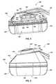
- FIG. 5is a cross-sectional side view of a portion of the headphone 302 of FIG. 3 .
- the headphone 302may include the speaker assembly 308 connected to the headband 310 .
- the headphone 302may include two such speaker assemblies 308 on opposing sides of the headband 310 .
- the speaker assembly 308may have an ear cup configuration configured to rest on or over the ear of the user.
- the speaker assembly 308may include a cushion 520 and an air cavity 530 for comfort when worn over the ear of the user.
- the speaker assembly 308may further include an audio driver 440 configured to emit sound at audible frequencies, and an additional, separate tactile bass vibrator 450 configured to emit low bass frequencies and to generate tactile vibrations within the speaker assembly 308 that may be felt by the user.
- the speaker assembly 308may further include a plate 542 positioned between the audio driver 440 and the air cavity 530 .
- the tactile bass vibrator 450may be located within a housing of the speaker assembly 308 .
- the tactile bass vibrator 450may include a suspension member 552 configured for mounting a vibration member 556 thereon.
- the suspension member 552may suspend the vibration member 556 on a radially inner platform portion of the suspension member 552 .
- the vibration member 556may be attached to the underside of the suspension member 552 .
- the suspension member 552may further include a radially outer portion. Further detail regarding the suspension member 552 will be described below with regard to FIGS. 7 through 14 .
- the tactile bass vibrator 450may further include a support structure 560 having a circumferentially extending rim 562 .
- the radially outer portion of the suspension member 552may be connected to the circumferentially extending rim 562 , such as by a fastener, a snap fit, etc.
- the suspension member 552may be integrally formed with the support structure 560 .
- the tactile bass vibrator 450may further include one or more additional magnetic elements (e.g., coils 558 ).
- the coils 558may be configured to generate a magnetic field responsive to an audio signal (e.g., second split audio signal 405 ( FIG. 4 )).
- the coils 558may be connected to the support structure 560 within a cavity between the support structure 560 and the suspension member 552 , such that the vibration member 556 may be within the magnetic field generated by the coils 558 .
- the support structure 560 and the suspension member 552may be connected to a frame support member 544 of the speaker assembly 308 , which may position the tactile bass vibrator 450 above the audio driver 440 , or in other words, on a side of the audio driver 440 that is opposite the ear of a person using the headphone 302 .
- the suspension member 552may be attached directly to the frame support member 544 such that the frame support member 544 is the support structure for the suspension member 552 .
- the vibration member 556may be configured to be displaced relative to the support structure 560 during operation of the speaker assembly 308 for generating tactile vibrations within the speaker assembly 308 that may be felt by the user.
- the tactile bass vibrator 450may exhibit a resonant frequency that is at least partially a function of the mass of the vibration member 556 , as well as the configuration of the suspension member 552 and the composition of the material of the suspension member 552 .
- an additional weight 554may be attached to the suspension member 552 to provide additional mass, which may increase the effect of the vibration and further contribute to the overall resonant frequency of the tactile bass vibrator 450 .
- the audio driver 440may produce audible sound waves responsive to an input audio signal.
- the input audio signal 401( FIG. 4 ) may be an audio signal received from a media player 306 ( FIG. 3 ).
- the audio signal 401 transmitted by the media player 306may be split and transmitted separately to each of the audio driver 440 and the tactile bass vibrator 450 . (See FIG. 4 ).
- the tactile bass vibrator 450may not be configured to generate audible high frequency sound. In some embodiments, medium and/or high frequencies may be filtered from the audio signal 401 prior to conveying the audio signal 401 to the tactile bass vibrator 450 .
- the coils 558may receive the audio signal (e.g., second split audio signal 405 ) and generate a magnetic field in response to the current flowing through the coils 558 .
- the magnetic fieldmay vary based, at least in part, on the frequency of the audio signal.
- the vibration member 556 and the suspension member 552may respond to the changing magnetic field by the vibration member 556 being displaced relative to the support structure 560 . As a result, the vibration member 556 and the suspension member 552 may produce audible sound in the bass frequencies.
- the tactile bass vibrator 450may also cause vibrations within the speaker assembly 308 while the vibration member 556 is displaced.
- the tactile bass vibrator 450may be oriented horizontally along with the plate 542 .
- the vibrations of the tactile bass vibrator 450may be at least substantially perpendicular to the plate 542 .
- the vibrations caused from the displacement of the tactile bass vibrator 450may cause the plate 542 to vibrate. While vibrating, the plate 542 may produce pressure waves in the air cavity 530 , which may enhance the bass frequencies, and, in particular, having a peak at the resonant frequency of the tactile bass vibrator 450 .
- the pressure waves and other physical vibrations in the headphone 302may also be felt as vibrations to the user, which may further enhance the user's listening experience. Some modifications to the headphone 302 may affect the feel of the vibrations generated by the bass. For example, the size of the air cavity 530 may affect the strength of the vibrations. Forming apertures in the plate 542 may also have a similar effect as increasing the size of the air cavity 530 , as the effective size of the air cavity 530 would be increased.
- the vibration member 556may be configured to passively produce a magnetic field.
- the vibration member 556may comprise a physical magnet located within the active magnetic field generated by the coils.
- the vibration member 556may be configured to actively produce a magnetic field, such as including coils that receive the audio signal.
- the coils 558may be replaced with a physical magnet fixedly attached to the support structure 560 .
- the presence of the physical magnetmay cause the vibration member 556 (coils in this embodiment) to be displaced relative to the support structure 560 .
- FIG. 6is a side view of a portion of a headphone 602 according to another embodiment of the present disclosure.
- the headphone 602may be in an ear cup configuration, which may include a headband 610 connected to a speaker assembly 608 .
- the speaker assembly 608may include a cushion padding 620 and an air cavity 630 for comfort when worn over the ears of a user.
- the speaker assembly 608may further include an audio driver (not shown) located within a housing 612 of the speaker assembly 608 .
- the audio drivermay be configured generally as discussed above.
- the speaker assembly 608may further include a tactile bass vibrator 650 .
- the tactile bass vibrator 650may be configured generally as discussed above.
- the tactile bass vibrator 650including a suspension member 652 configured for mounting a vibration member (not shown) thereon.
- the suspension member 652may also have an additional optional weight 654 mounted thereon.
- the tactile bass vibrator 650may further include a support structure 660 having a circumferentially extending rim 662 .
- the vibration member (not shown) and additional optional weight 654may be configured to be displaced relative to the support structure 660 during operation of the speaker assembly 608 .
- the tactile bass vibrator 650may be connected to an external surface of the speaker assembly 608 .
- the tactile bass vibrator 650may be rigidly attached to a back surface 614 of the housing 612 , or a portion of the headband 610 for generating low frequency vibrations that may be felt by the user.
- the tactile bass vibrator 650may be connected at least substantially horizontal with a plate (not shown) connected with the housing 612 between the audio driver and the air cavity 630 .
- the tactile bass vibrator 650may cause vibrations in the plate that produce pressure waves and other vibrations that are felt by the user.
- FIGS. 5 and 6each show a single speaker assembly 308 , 608 for each headphone 302 , 602 ; however, it should be recognized that the headbands 310 , 610 may be coupled to two such speaker assemblies 308 , 608 (i.e., one for each ear).
- each pair of speaker assemblies 308 , 608may be configured the same.
- the resonant frequencies of each of the tactile bass vibrators 450 , 650may be the same for the right speaker assembly as well as the left speaker assembly.
- the speaker assemblies of a headphonemay have different components therein.
- one of the speaker assembliesmay include a battery for providing power thereto.
- the added weight of the batterymay affect the resonant overall resonant frequency of the tactile base vibrator associated with that headphone.
- the tactile bass vibrator on one side of the headphonemay be configured to exhibit a resonant frequency that is different than the tactile bass vibrator on the other side of the headphone.
- the overall effect of the resonant frequency for vibration of each of the speaker assembliesmay be approximately the same.
- different weightsmay be attached to the suspension members of one or both of the speaker assemblies to alter the resonant frequency of one of the tactile bass vibrator such that the overall effect of the resonant frequencies for each speaker assembly is approximately the same.
- a combination of different configurations of suspension members and different weightsmay be used.
- each of the speaker assembliesmay contribute to a non-uniform response for the audio driver 440 , the tactile bass vibrator 450 , or both.
- the respective responsesmay be non-uniform.
- electrical performance of one or more driversmay be different due to tolerances within the drivers.
- the channel gain for each speaker assemblymay be balanced.
- the audio signal to one speaker assemblymay be amplified relative to the audio signal of the other speaker assembly.
- FIG. 20shows a plurality of speakers assemblies 308 A, 308 B configured for channel gain balancing.
- the first speaker assembly 308 Amay be coupled to a first adjustable resistor 320
- the second speaker assembly 308 Bmay be coupled to a second adjustable resistor 322 in the path of the audio signal 401 (e.g., from an amplifier).
- the resistor values of the first adjustable resistor 320 and the second adjustable resistor 322may be adjusted by a controller until the response for the speaker assemblies 308 A, 308 B are approximately the same (i.e., balanced, uniform, etc.).
- adjustable resistorsmay be coupled in the path of the split audio signals 403 , 405 ( FIG. 4 ) such that the channel gain of the audio driver 440 and tactile bass vibrator 450 may be adjusted separately.
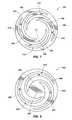
- FIG. 7is a top plan view of the suspension member 552 for the tactile bass vibrator 450 of FIG. 5 .
- the suspension member 552may include a radially outer portion 702 and a radially inner platform portion 704 .
- the radially outer portion 702 of the suspension member 552may be attached to the rim 562 ( FIG. 5 ) of the support structure 560 ( FIG. 5 ), and the radially outer portion 702 may be attached to the vibration member 556 ( FIG. 5 ).
- the vibration member 556may be attached proximate a center 706 of the radially inner platform portion 704 .
- Each of the radially outer portion 702 and the radially inner platform portion 704may be generally circular.
- the center 706 of the radially inner platform portion 704may also be substantially near the center of the circle defined by the radially outer portion 702 . In other words, the radially outer portion 702 and the radially inner platform portion 704 may be concentric.
- the radially outer portion 702 and the radially inner platform portion 704may be connected to one another by a plurality of beams 708 .
- the shape and dimensions of the beams 708may affect the resonant frequency of the suspension member 552 with the vibration member 556 ( FIG. 5 ) attached thereto.
- the plurality of beams 708may be configured such that a resonant frequency of the vibration member 556 attached to the radially inner platform portion 704 of the suspension member 552 scales linearly with a beam width (w) of each beam 708 of the plurality of beams 708 .
- the beams 708may be separated from each other by apertures 710 therebetween. Each beam 708 may contact the radially inner platform portion 704 at a respective single location, and each beam 708 may contact the radially outer portion 702 at a respective single location. Each beam 708 may not intersect or otherwise directly contact any of the other beams 708 . In other words, each beam 708 connects one point of the radially outer portion 702 with one point of the radially inner platform portion 704 . Each beam 708 may extend in a generally spiral direction from the radially outer portion 702 of the suspension member 552 to the radially inner platform portion 704 .
- each of the beams 708may extend in a common spiral direction from the radially outer portion 702 of the suspension member 552 to the radially inner platform portion 704 .
- each of the beams 708may extend in a counter-clockwise direction moving radially inward from the radially outer portion 702 to the radially inner platform portion 704 as shown in FIG. 7 .
- each of the beams 708may extend in a clockwise direction moving radially inward from the radially outer portion 702 to the radially inner platform portion 704 .
- the beams 708may have a monotonic common spiral directionality, and may not bend to change direction, as in the conventional speaker assembly shown in FIG. 2 .
- the beams 708may extend smoothly and continuously in a common generally spiral direction between the radially outer portion 702 and the radially inner platform portion 704 without substantial corners (i.e., bends) or distinct transitions in the spiral direction. Doing so may reduce the stress concentrations and torsional stress along the beams 708 , and may also result in the resonant frequency scaling linearly with the beam width (w).
- a changing magnetic field responsive to the audio signal received by the tactile bass vibrator 450may cause displacement of the vibration member 556 ( FIG. 5 ) and the suspension member 552 .
- the vibration member 556may assist the suspension member 552 in vibrating.
- Vibration of the suspension member 552may cause an increased bass response, as well as cause a tactile response (e.g., vibrations).
- a tactile responsemay be felt by a user, such that the user's listening experience may be enhanced.
- the received audio signalis at the resonant frequency of the attached vibration member 556 and the suspension member 552 , the speaker may resonate, which may result in an increased bass response and tactile response at that resonant frequency.
- the suspension member 552may be formed from a metal material, which may have a stiffness of the material that may affect the resonant frequency of the suspension member 552 , as well as the deflection of the vibration member 556 . For example, reducing the stiffness of the suspension member 552 may increase the deflection of the vibration member 556 .
- Using a metal for the suspension member 552may further permit lower resonance and therefore, a smaller casing, in comparison to other materials (e.g., plastic) that may be used.
- metal materialsmay be relatively strong and less likely to fatigue over time in comparison to some materials.
- Forming the suspension member 552may include methods of forming and shaping a metal, such as laser cutting, press cutting, and other metal shaping and fabrication methods known in the art.
- FIG. 8is a top view of a suspension member 852 for a speaker according to an embodiment of the present disclosure.
- the suspension member 852may have a structure that scales linearly with beam width (w).
- the suspension member 852includes radially outer portion 802 and a radially inner platform portion 804 for mounting a magnet (not shown) proximate a center 806 of the radially inner platform portion 804 .
- Each of the radially outer portion 802 and the radially inner platform portion 804may be generally circular.
- the radially outer portion 802 and the radially inner platform portion 804may be connected through a plurality of beams 808 .
- the plurality of beams 808may be separated from each other through a plurality of apertures 810 therebetween.
- the plurality of beams 808may be configured similar to the plurality of beams 708 of FIG. 7 .
- the plurality of beams 808may be configured such that a resonant frequency of the vibration member attached to the radially inner platform portion 804 of the suspension member 852 scales linearly with a beam width (w) of each beam of the plurality of beams 808 .
- the suspension member 852 of FIG. 8includes three beams 808 . Some embodiments may include from two to five beams, although embodiments of the present disclosure may include any number of beams.
- FIG. 9is a graph 900 showing resonant frequency (Hz) for a variety of beam widths (mm).
- the graph 900shows that resonant frequency scales linearly with beam width (w).
- the resonant frequencyincreases linearly as the beam widths increase.
- FIG. 10is a graph 1000 showing stability of the suspension member (1/mm) for a variety of beam widths. Stability is defined as the reciprocal of the deflection (mm) of the magnet when the suspension member is resonating. According to embodiments of the present disclosure, as the beam widths increase, the stability may also improve.
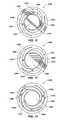
- FIGS. 11, 12, and 13are top views of suspension members 1100 , 1200 , and 1300 , respectively, which may be incorporated with a speaker assembly of a headphone.
- the suspension member 1100may include a radially outer portion 1102 , and a radially inner platform portion 1104 for mounting a vibration member substantially near a center 1106 thereof.
- the radially outer portion 1102 and the radially inner platform portion 1104may be connected together through a plurality of beams 1108 separated by apertures 1110 .
- the suspension member 1200may include a radially outer portion 1202 , and a radially inner platform portion 1204 for mounting a vibration member substantially near a center 1206 thereof.
- the radially outer portion 1202 and the radially inner platform portion 1204may be connected together through a plurality of beams 1208 separated by apertures 1210 .
- the suspension member 1300may include a radially outer portion 1302 , and a radially inner platform portion 1304 for mounting a vibration member substantially near a center 1306 thereof.
- the radially outer portion 1302 and the radially inner platform portion 1304may be connected together through a plurality of beams 1308 separated by apertures 1310 .
- the suspension members 1100 , 1200 , 1300may be configured to exhibit a particular resonant frequency (in the assembled state within the tactile bass vibrators).
- the resonant frequencies of the suspension members 1100 , 1200 , 1300may be scaled according to the width of the respective beams 1108 , 1208 , 1308 , which scaling may be linear with beam width (w).
- the beams 1108may be narrower than the beams 1208 , which may be narrower than the beams 1308 .
- the resonant frequency (e.g., 83 Hz) of the suspension member 1100may be greater than the resonant frequency (e.g., 65 Hz) of the suspension member 1200 , which may be greater than the resonant frequency (e.g., 56 Hz) of the suspension member 1300 .
- a changing magnetic field responsive to the audio signal received by the tactile bass vibrator 450may cause displacement of the vibration member 556 ( FIG. 5 ) and the suspension members 1100 , 1200 , 1300 .
- the vibration member 556may assist the suspension members 1100 , 1200 , 1300 in vibrating. Vibration of the suspension members 1100 , 1200 , 1300 may cause an increased bass response, as well as cause a tactile response (e.g., vibrations). Such a tactile response may be felt by the user, such that the user's listening experience may be enhanced.
- the speakermay resonate, which may result in an increased bass response and tactile response at that resonant frequency.
- Having a design that scales the resonant frequency linearly for a dimension of the beams 1108 , 1208 , 1308may provide methods for tuning the resonant frequency in a predictable manner so that time and money are not wasted producing speakers that do not adequately meet desired requirements.
- FIG. 14is a flowchart 1400 for a method of forming a speaker.
- a suspension membermay be provided.
- the suspension membermay include a radially outer portion, a radially inner platform portion, and a plurality of beams. Each beam of the plurality of beams may extend from the radially outer portion to the radially inner platform portion.
- the beams of the plurality of beamsmay be configured such that a resonant frequency of a vibration member attached to the radially inner platform portion of the suspension member scales linearly with a beam width (w) of the beams of the plurality of beams.
- the suspension membermay also be selected to comprise a metal suspension member.
- a vibration membermay be provided.
- the vibration membermay be attached to the radially inner platform portion of the suspension member.
- the vibration membermay be selected to comprise a physical magnet that is configured to be displaced with the suspension member relative one or more coils that actively generate a magnetic field responsive to an audio signal.
- the coilsmay be fixedly attached to a support structure.
- the vibration membermay be selected to comprise a coil configured to actively generate a magnetic field responsive to the audio signal, wherein the magnetic object is a physical magnet fixedly attached to the support structure.
- the suspension membermay be attached to the support structure.
- the radially outer portion of the suspension membermay be attached to a rim of the support member such that the vibration member is suspended relative to the support member.
- FIG. 15is a flowchart 1500 for a method of forming a speaker.
- the methodmay include forming the speaker to have a resonant frequency tuned to a specific media content.
- a bass frequency of the media contentmay be determined.
- the bass frequencymay be determined by sampling an electrical audio signal for a media device having media content stored thereon.
- Media contentmay include a movie, music, a video game, and other media content that includes audio content.
- a spectrum analysis of the sampled audio contentmay also be performed.
- the bass frequency of interestmay be the peak bass frequency of the media content.
- a suspension membermay be formed that is tuned to the media content, such as to a bass frequency of interest (e.g., peak bass frequency of the media content).
- the suspension membermay be formed from a metal material to include a plurality of beams that curve in a single general direction around the suspension member connecting a radially outer portion and a radially inner platform portion. The dimensions of the beams may be configured to tune the speaker to exhibit a resonant frequency that is approximately the peak bass frequency of the media content of the media device.
- the shape of the beamsmay be smooth and continuous, and may scale linearly with the resonant frequency.
- the plurality of beamsmay be configured such that the resonant frequency of the vibration member attached to the radially inner platform portion of the suspension member is between approximately 40 Hz and approximately 60 Hz.
- each beam of the plurality of beamsmay be formed to extend in a spiral direction from the radially outer portion of the suspension member to the radially inner platform portion. In some embodiments, each beam of the plurality of beams may be formed to extend in a common spiral direction from the radially outer portion of the suspension member to the radially inner platform portion. In some embodiments, each beam of the plurality of beams may be formed to extend continuously without bends in the spiral direction from the radially outer portion of the suspension member to the radially inner platform portion. In some embodiments, the beams of the plurality of beams may be located such that they do not intersect one another.
- the suspension membermay then be provided and attached to a vibration member and a rim of a support member to form a speaker as discussed above with respect to FIG. 14 .
- the speakermay also be packaged with a media storage device that includes the media content to which the speaker is tuned.
- the speaker and media storage devicemay be packaged in a common package for sale or distribution, such as, for example, as a kit.
- FIG. 16is a graph 1600 showing a spectral analysis of a media content.
- the media contentmay be a video game, such as “Mass Effect 3 .”
- the frequencies (in Hz) present in a sampled audio signal 1610are measured along the X-axis, and the signal power (in dB) of the sampled audio signal 1610 are measured along the Y-axis.
- the bass frequenciesinclude relatively low audible frequencies in the range of approximately 16 Hz and approximately 200 Hz. As shown in FIG.
- the sampled audio signal 1610 for the media contenthas a peak bass frequency 1612 (i.e., a frequency within the bass frequencies at which a power peak is determined, or any frequency within a range of frequencies when a power peak extends over a range of frequencies).
- the peak bass frequencymay be a frequency in the range of approximately 30 Hz to approximately 50 Hz.
- the speakermay be considered to be tuned to the media content if the resonant frequency of the speaker is any frequency within the range of approximately 30 Hz to approximately 50 Hz.
- FIG. 17is a graph 1700 showing a spectral analysis of a media content.
- the media contentmay be music, such as the song “Take the Power Back” by the group “Rage against the Machine.”
- the frequencies (in Hz) present in a sampled audio signal 1710are measured along the X-axis
- the power (in dB) of the sampled audio signal 1710are measured along the Y-axis.
- the sampled audio signal 1710 for the media contenthas a peak bass frequency 1712 within the range of approximately 60 Hz to approximately 70 Hz.
- the speakermay be considered to be tuned to the media content if the resonant frequency of the speaker is any frequency within the range of approximately 60 Hz to approximately 70 Hz.
- FIG. 18is a graph 1800 showing a spectral analysis of a media content.
- the media contentmay be a movie, such as the movie “Transformers 3 .”
- the frequencies (in Hz) present in a sampled audio signal 1810are measured along the X-axis, and the power (in dB) of the sampled audio signal 1810 are measured along the Y-axis.
- the sampled audio signal 1810 for the media contenthas a peak bass frequency 1812 within the range of approximately 50 Hz to approximately 60 Hz.
- the speakermay be considered to be tuned to the media content if the speaker is configured to exhibit a resonant frequency of the speaker is any frequency within the range of approximately 50 Hz to approximately 60 Hz.
- FIG. 19is a kit 1900 that includes at least one speaker 1910 and a storage device 1920 .
- the storage devicemay store media content 1930 that is configured to generate an audio signal, such as when played by a media player.
- the at least one speaker 1910may be configured generally as described above.
- the at least one speakermay include a support member having a circumferentially extending rim, a vibration member configured to be displaced relative to the support structure responsive to receipt of the electrical audio signal when sent to the at least one speaker by a media player playing the media content, and a suspension member suspending the vibration member relative to the support member.
- the suspension membermay include a radially outer portion attached to the rim of the support member and a radially inner platform portion attached to the vibration member.
- the suspension membermay further include a plurality of beams, each beam of the plurality of beams extending from the radially outer portion to the radially inner platform portion.
- the beams of the plurality of beamsmay be configured such that a resonant frequency of the vibration member attached to the radially inner platform portion of the suspension member is at least approximately equal to a peak bass frequency of the electrical audio signal.
- the resonant frequency of a tactile bass vibratori.e., speaker 1910
- the storage device 1920 including the media content 1930may be packaged and sold with the at least one speaker 1910 in a common package 1902 .
- the at least one speaker 1910may be included within a headphone.
- the storage device 1920may include any type of computer-readable storage media, such as, for example, a compact disc (CD), a digital video disc (DVD), a BLU-RAY DISC®, a Flash memory device, a gaming device, and other types of memory devices for storing information.
- the media content 1930may include, for example, music, a movie, and a video game.
- a speakercomprising: a support structure having a circumferentially extending rim; a vibration member configured to be displaced relative to the support structure during operation of the speaker for generating vibrations; and a suspension member suspending the vibration member relative to the support structure, the suspension member including: a radially outer portion attached to the rim of the support structure; a radially inner platform portion attached to the vibration member; and a plurality of beams, each beam of the plurality of beams extending from the radially outer portion to the radially inner platform portion, wherein the plurality of beams is configured such that a resonant frequency of the vibration member attached to the radially inner platform portion of the suspension member scales linearly with a beam width of the beams of the plurality of beams.
- vibration membercomprises an electrical coil configured to generate a magnetic field responsive to an audio signal.
- each beam of the plurality of beamsextends in a spiral direction from the radially outer portion of the suspension member to the radially inner platform portion.
- each beam of the plurality of beamsextends in a common spiral direction from the radially outer portion of the suspension member to the radially inner platform portion.
- each beam of the plurality of beamsextends continuously without bends in the spiral direction from the radially outer portion of the suspension member to the radially inner platform portion.
- a speakercomprising: a support structure having a circumferentially extending rim; a vibration member configured to be displaced within the support structure for generating vibrations during operation of the speaker; and a suspension member suspending the vibration member relative to the support structure, the suspension member including a radially outer portion attached to the rim of the support structure and a radially inner platform portion attached to the vibration member, the suspension member further including a plurality of beams, each beam of the plurality of beams extending from the radially outer portion to the radially inner platform portion, wherein each beam of the plurality of beams extends in a spiral direction from the radially outer portion of the suspension member to the radially inner platform portion.
- each beam of the plurality of beamsextends in a common spiral direction from the radially outer portion of the suspension member to the radially inner platform portion.
- each beam of the plurality of beamsextends continuously without bends in the spiral direction from the radially outer portion of the suspension member to the radially inner platform portion.
- a headphoneincluding at least one speaker and a device for operatively coupling the at least one speaker with a media player configured to send an electrical audio signal to the at least one speaker
- the at least one speakercomprising: a support structure having a circumferentially extending rim; a vibration member configured to be displaced within the support structure and generate vibrations responsive to receipt of the electrical audio signal sent to the at least one speaker by the media player; and a suspension member suspending the vibration member relative to the support structure, the suspension member including a radially outer portion attached to the rim of the support structure and a radially inner platform portion attached to the vibration member, the suspension member further including a plurality of beams, each beam of the plurality of beams extending from the radially outer portion to the radially inner platform portion, wherein the beams of the plurality of beams are configured such that a resonant frequency of the vibration member attached to the radially inner platform portion of the suspension member scales linearly with a beam width of the beams of the plurality of beam
- the headphone of Embodiment 16further comprising a headband, the at least one speaker attached to the headband.
- a method of forming a speakercomprising: providing a suspension member including a radially outer portion, a radially inner platform portion, and a plurality of beams, each beam of the plurality of beams extending from the radially outer portion to the radially inner platform portion, the beams of the plurality of beams configured such that a resonant frequency of a vibration member attached to the radially inner platform portion of the suspension member scales linearly with a beam width of the beams of the plurality of beams; attaching the vibration member to the radially inner platform portion of the suspension member; and attaching the radially outer portion of the suspension member to a rim of a support structure such that the vibration member is suspended relative to the support structure.
- Embodiment 20further comprising selecting the vibration member to comprise a physical magnet.
- Embodiment 20 or Embodiment 21further comprising selecting the suspension member to comprise a metal suspension member.
- Embodiment 23wherein forming the suspension member comprises configuring the beams of the plurality of beams such that the resonant frequency of the vibration member attached to the radially inner platform portion of the suspension member is between approximately 40 Hz and approximately 60 Hz.
- Embodiment 23 or Embodiment 24, wherein forming the suspension membercomprises forming each beam of the plurality of beams to extend in a spiral direction from the radially outer portion of the suspension member to the radially inner platform portion.
- forming the suspension memberfurther comprises forming each beam of the plurality of beams to extend in a common spiral direction from the radially outer portion of the suspension member to the radially inner platform portion.
- forming the suspension membercomprises forming each beam of the plurality of beams to extend continuously without bends in the spiral direction from the radially outer portion of the suspension member to the radially inner platform portion.
- forming the suspension membercomprises locating and configuring the beams of the plurality of beams such that they do not intersect one another.
- forming the suspension membercomprises forming a metal suspension member.
- any of Embodiments 20 through 29,further comprising: sampling an electrical audio signal for a media device; determining a peak bass frequency of the electrical audio signal; and configuring the beams of the plurality of beams of the suspension member such that the resonant frequency of the vibration member attached to the radially inner platform portion of the suspension member is at least approximately equal to the peak bass frequency of the electrical audio signal of the media device.
- Embodiment 30further comprising packaging the speaker and the media device in a common package for sale or distribution.
- the at least one speakercomprises: a support structure having a circumferentially extending rim; a vibration member configured to be displaced within the support structure for generating vibrations responsive to receipt of the electrical audio signal when sent to the at least one speaker by a media player playing the media content; and a suspension member suspending the vibration member relative to the support structure, the suspension member including a radially outer portion attached to the rim of the support structure and a radially inner platform portion attached to the vibration member, the suspension member further including a plurality of beams, each beam of the plurality of beams extending from the radially outer portion to the radially inner platform portion, wherein the beams of the plurality of beams are configured such that a resonant frequency of the vibration member attached to the radially inner platform portion of the suspension member is at least approximately equal to a peak bass frequency of the electrical audio signal.
- the kit of Embodiment 32wherein the media content is selected from the group consisting of music, a movie, and a video game.
Landscapes
- Engineering & Computer Science (AREA)
- Physics & Mathematics (AREA)
- Acoustics & Sound (AREA)
- Signal Processing (AREA)
- Manufacturing & Machinery (AREA)
- Details Of Audible-Bandwidth Transducers (AREA)
- Audible-Bandwidth Dynamoelectric Transducers Other Than Pickups (AREA)
- Headphones And Earphones (AREA)
Abstract
Description
Claims (20)
Priority Applications (1)
| Application Number | Priority Date | Filing Date | Title |
|---|---|---|---|
| US14/630,556US9609421B2 (en) | 2012-08-23 | 2015-02-24 | Apparatus and methods related to a tactile vibrator for a speaker system |
Applications Claiming Priority (3)
| Application Number | Priority Date | Filing Date | Title |
|---|---|---|---|
| US201261692570P | 2012-08-23 | 2012-08-23 | |
| US13/969,188US8965028B2 (en) | 2012-08-23 | 2013-08-16 | Speakers, headphones, and kits related to vibrations in an audio system, and methods for forming same |
| US14/630,556US9609421B2 (en) | 2012-08-23 | 2015-02-24 | Apparatus and methods related to a tactile vibrator for a speaker system |
Related Parent Applications (1)
| Application Number | Title | Priority Date | Filing Date |
|---|---|---|---|
| US13/969,188ContinuationUS8965028B2 (en) | 2012-08-23 | 2013-08-16 | Speakers, headphones, and kits related to vibrations in an audio system, and methods for forming same |
Publications (2)
| Publication Number | Publication Date |
|---|---|
| US20150172805A1 US20150172805A1 (en) | 2015-06-18 |
| US9609421B2true US9609421B2 (en) | 2017-03-28 |
Family
ID=48998533
Family Applications (2)
| Application Number | Title | Priority Date | Filing Date |
|---|---|---|---|
| US13/969,188ActiveUS8965028B2 (en) | 2012-08-23 | 2013-08-16 | Speakers, headphones, and kits related to vibrations in an audio system, and methods for forming same |
| US14/630,556ActiveUS9609421B2 (en) | 2012-08-23 | 2015-02-24 | Apparatus and methods related to a tactile vibrator for a speaker system |
Family Applications Before (1)
| Application Number | Title | Priority Date | Filing Date |
|---|---|---|---|
| US13/969,188ActiveUS8965028B2 (en) | 2012-08-23 | 2013-08-16 | Speakers, headphones, and kits related to vibrations in an audio system, and methods for forming same |
Country Status (3)
| Country | Link |
|---|---|
| US (2) | US8965028B2 (en) |
| EP (1) | EP2701400B1 (en) |
| CN (1) | CN103634727B (en) |
Cited By (1)
| Publication number | Priority date | Publication date | Assignee | Title |
|---|---|---|---|---|
| US10152296B2 (en) | 2016-12-28 | 2018-12-11 | Harman International Industries, Incorporated | Apparatus and method for providing a personalized bass tactile output associated with an audio signal |
Families Citing this family (66)
| Publication number | Priority date | Publication date | Assignee | Title |
|---|---|---|---|---|
| USD326918S (en)* | 1991-03-19 | 1992-06-09 | Roberts Sally L | Pacifier holder |
| US9237395B2 (en) | 2009-11-25 | 2016-01-12 | Skullcandy, Inc. | Modular audio systems and related assemblies and methods |
| US9467780B2 (en) | 2010-01-06 | 2016-10-11 | Skullcandy, Inc. | DJ mixing headphones |
| US9422094B2 (en) | 2011-11-15 | 2016-08-23 | Skullcandy, Inc. | Packaging for headphones, packaged headphones, and related methods |
| US8942403B2 (en) | 2011-11-18 | 2015-01-27 | Skullcandy, Inc. | Wiring harness for clothing, electronic devices including such a wiring harness, and garments incorporating such a wiring harness and electronic device |
| US9100745B2 (en) | 2012-01-09 | 2015-08-04 | Skullcandy, Inc. | Modular audio devices configured to emit differing sound profiles and related methods |
| US9439467B2 (en) | 2012-01-24 | 2016-09-13 | Skullcandy, Inc. | Accessory structures for connection between straps and related methods |
| US8965028B2 (en) | 2012-08-23 | 2015-02-24 | Skullcandy, Inc. | Speakers, headphones, and kits related to vibrations in an audio system, and methods for forming same |
| US8845366B2 (en)* | 2012-12-17 | 2014-09-30 | Derrick Lewis Brown | Apparatus, system and method for composite and symmetrical hybrid electronic connectors |
| US9414145B2 (en) | 2013-03-15 | 2016-08-09 | Skullcandy, Inc. | Customizable headphone audio driver assembly, headphone including such an audio driver assembly, and related methods |
| USD733682S1 (en) | 2013-09-25 | 2015-07-07 | Skullcandy, Inc. | Portable speaker |
| EP2890153B1 (en) | 2013-12-30 | 2020-02-26 | Skullcandy, Inc. | Headphones for stereo tactile vibration, and related systems and methods |
| US8977376B1 (en)* | 2014-01-06 | 2015-03-10 | Alpine Electronics of Silicon Valley, Inc. | Reproducing audio signals with a haptic apparatus on acoustic headphones and their calibration and measurement |
| USD728533S1 (en) | 2014-03-31 | 2015-05-05 | Skullcandy, Inc. | Headphone |
| USD790506S1 (en)* | 2014-07-02 | 2017-06-27 | Sonetics Holdings, Inc. | Communication headset |
| USD750042S1 (en) | 2014-07-14 | 2016-02-23 | Skullcandy, Inc. | Headphone microphone |
| USD757678S1 (en) | 2014-07-25 | 2016-05-31 | Skullcandy, Inc. | Portable speaker |
| US10034112B2 (en) | 2014-07-25 | 2018-07-24 | Skullcandy, Inc. | Mass port plug for customizing headphone drivers, and related methods |
| USD758989S1 (en) | 2014-07-25 | 2016-06-14 | Skullcandy, Inc. | Portable speaker |
| USD758336S1 (en) | 2014-07-25 | 2016-06-07 | Skullcandy, Inc. | Portable speaker |
| US9483922B2 (en)* | 2014-09-04 | 2016-11-01 | Glenn Kawamoto | Shaker apparatus and related methods of transmitting vibrational energy to recipients |
| KR20170060114A (en) | 2014-09-24 | 2017-05-31 | 택션 테크놀로지 인코포레이티드 | Systems and methods for generating damped electromagnetically actuated planar motion for audio-frequency vibrations |
| JP6409188B2 (en)* | 2014-11-18 | 2018-10-24 | 株式会社オーディオテクニカ | Electroacoustic transducer and acoustic resistance material |
| US9883290B2 (en) | 2014-12-31 | 2018-01-30 | Skullcandy, Inc. | Audio driver assembly, headphone including such an audio driver assembly, and related methods |
| EP3041258B1 (en) | 2014-12-31 | 2018-02-28 | Skullcandy, Inc. | Methods of generating tactile user feedback utilizing headphone devices and related systems |
| EP3041261B1 (en) | 2014-12-31 | 2020-05-06 | Skullcandy, Inc. | Speaker assemblies for passive generation of vibrations and related headphone devices and methods |
| USD757680S1 (en) | 2015-01-05 | 2016-05-31 | Skullcandy, Inc. | Headphone |
| US9936273B2 (en) | 2015-01-20 | 2018-04-03 | Taction Technology, Inc. | Apparatus and methods for altering the appearance of wearable devices |
| US9648412B2 (en)* | 2015-02-06 | 2017-05-09 | Skullcandy, Inc. | Speakers and headphones related to vibrations in an audio system, and methods for operating same |
| US9706288B2 (en)* | 2015-03-12 | 2017-07-11 | Apple Inc. | Apparatus and method of active noise cancellation in a personal listening device |
| US20160277821A1 (en)* | 2015-03-19 | 2016-09-22 | Panasonic Intellectual Property Management Co., Ltd. | Vibration headphones |
| US9918154B2 (en)* | 2015-07-30 | 2018-03-13 | Skullcandy, Inc. | Tactile vibration drivers for use in audio systems, and methods for operating same |
| US10390139B2 (en)* | 2015-09-16 | 2019-08-20 | Taction Technology, Inc. | Apparatus and methods for audio-tactile spatialization of sound and perception of bass |
| US10573139B2 (en) | 2015-09-16 | 2020-02-25 | Taction Technology, Inc. | Tactile transducer with digital signal processing for improved fidelity |
| USD824879S1 (en) | 2015-11-18 | 2018-08-07 | Skullcandy, Inc. | Portable speaker |
| USD824365S1 (en) | 2015-11-18 | 2018-07-31 | Skullcandy, Inc. | Portable speaker |
| USD787470S1 (en)* | 2015-12-10 | 2017-05-23 | Skullcandy, Inc. | Headphone |
| CN105611453B (en)* | 2016-03-23 | 2019-02-15 | 中名(东莞)电子有限公司 | Active mobile flat plate bass enhancing earphone |
| JP2019041271A (en)* | 2017-08-25 | 2019-03-14 | オンキヨー株式会社 | Frame, speaker unit employing the same, headphone, and earphone |
| US10872592B2 (en)* | 2017-12-15 | 2020-12-22 | Skullcandy, Inc. | Noise-canceling headphones including multiple vibration members and related methods |
| US10484792B2 (en) | 2018-02-16 | 2019-11-19 | Skullcandy, Inc. | Headphone with noise cancellation of acoustic noise from tactile vibration driver |
| USD869432S1 (en)* | 2018-06-28 | 2019-12-10 | Skullcandy, Inc. | Headphone |
| USD868731S1 (en)* | 2018-07-12 | 2019-12-03 | Skullcandy, Inc. | Headphone |
| US10911855B2 (en)* | 2018-11-09 | 2021-02-02 | Vzr, Inc. | Headphone acoustic transformer |
| USD884671S1 (en)* | 2018-11-30 | 2020-05-19 | Shure Acquisition Holdings, Inc. | Headphone |
| USD887391S1 (en) | 2018-12-06 | 2020-06-16 | Razer (Asia-Pacific) Pte. Ltd. | Headphone |
| USD918177S1 (en)* | 2018-12-17 | 2021-05-04 | Sony Corporation | Earphone |
| USD903631S1 (en) | 2019-03-01 | 2020-12-01 | Shure Acquisition Holdings, Inc. | Headphone |
| USD910593S1 (en)* | 2019-03-08 | 2021-02-16 | Austrian Audio Gmbh | Headphones |
| USD896203S1 (en)* | 2019-04-02 | 2020-09-15 | Razer (Asia-Pacific) Pte. Ltd. | Headphone |
| GB201907267D0 (en)* | 2019-05-23 | 2019-07-10 | Pss Belgium Nv | Loudspeaker |
| US11032638B2 (en)* | 2019-07-16 | 2021-06-08 | Ngai Fun Cheung | Speaker with an integrated air pressure and vibration mitigation system |
| USD914635S1 (en)* | 2019-09-27 | 2021-03-30 | Razer (Asia-Pacific) Pte. Ltd. | Headphone |
| USD877716S1 (en)* | 2019-11-13 | 2020-03-10 | Shenzhen Qianhai Patuoxun Network And Technology Co., Ltd | Headphones |
| KR102696599B1 (en)* | 2020-04-30 | 2024-08-21 | 썬전 샥 컴퍼니, 리미티드 | Method for controlling a voice output device, a virtual sound source, and a method for controlling volume |
| USD946551S1 (en)* | 2020-07-01 | 2022-03-22 | ZhongTian DingSheng (Shenzhen) Industry Co., Ltd. | Earphone |
| CN111698608B (en) | 2020-07-02 | 2022-02-01 | 立讯精密工业股份有限公司 | Bone conduction earphone |
| CN111818409B (en)* | 2020-07-20 | 2022-03-25 | 潍坊歌尔微电子有限公司 | Bone voiceprint sensor and electronic device |
| USD970467S1 (en)* | 2020-09-17 | 2022-11-22 | Razer (Asia-Pacific) Pte. Ltd. | Headphone |
| US11700474B2 (en) | 2021-06-24 | 2023-07-11 | New Audio LLC | Multi-microphone headset |
| USD1000416S1 (en)* | 2021-06-24 | 2023-10-03 | New Audio LLC | Wireless headphones |
| USD991216S1 (en)* | 2021-07-06 | 2023-07-04 | Shenzhen Grandsun Industrial Design Co., Ltd. | Wireless headset |
| USD1001771S1 (en)* | 2021-08-26 | 2023-10-17 | Razer (Asia-Pacific) Pte. Ltd. | Headphone |
| USD1007463S1 (en) | 2021-09-02 | 2023-12-12 | Skullcandy, Inc. | Headphone |
| USD986853S1 (en) | 2021-09-02 | 2023-05-23 | Skullcandy, Inc. | Headphone |
| USD1055023S1 (en)* | 2021-11-19 | 2024-12-24 | Bose Corporation | Headset |
Citations (52)
| Publication number | Priority date | Publication date | Assignee | Title |
|---|---|---|---|---|
| US6377145B1 (en) | 1999-03-03 | 2002-04-23 | Tokin Corporation | Vibration actuator having magnetic circuit elastically supported by a spiral damper with increased compliance |
| US6603863B1 (en)* | 1998-12-25 | 2003-08-05 | Matsushita Electric Industrial Co., Ltd. | Headphone apparatus for providing dynamic sound with vibrations and method therefor |
| US20040064066A1 (en) | 2000-05-19 | 2004-04-01 | John Michael S. | System and method for objective evaluation of hearing using auditory steady-state responses |
| US6850138B1 (en)* | 1999-12-02 | 2005-02-01 | Nec Tokin Corporation | Vibration actuator having an elastic member between a suspension plate and a magnetic circuit device |
| US20060171553A1 (en)* | 2005-02-03 | 2006-08-03 | Nokia Corporation | Gaming headset vibrator |
| US20060262954A1 (en) | 2002-10-02 | 2006-11-23 | Oug-Ki Lee | Bone vibrating speaker using the diaphragm and mobile phone thereby |
| CA2697029A1 (en) | 2005-08-10 | 2007-02-10 | Skullcandy, Inc. | Personal portable integrator for music player and mobile phone |
| US7187948B2 (en) | 2002-04-09 | 2007-03-06 | Skullcandy, Inc. | Personal portable integrator for music player and mobile phone |
| EP1841278A1 (en) | 2006-03-27 | 2007-10-03 | Jui-Chen Huang | Loudspeaker with low-frequency oscillation |
| WO2010068495A2 (en) | 2008-11-25 | 2010-06-17 | Skullcandy, Inc. | Interchangeable headphone audio system |
| USD623627S1 (en) | 2010-01-06 | 2010-09-14 | Skullcandy, Inc. | Optic-shaped headphones |
| USD624057S1 (en) | 2010-01-06 | 2010-09-21 | Skullcandy, Inc. | Audio ear bud headphone with extended curvature |
| US20100239115A1 (en) | 2009-03-17 | 2010-09-23 | Naturalpoint, Inc. | Headset accessory device system |
| EP1760896B1 (en) | 2005-08-29 | 2010-09-29 | Skullcandy, Inc. | Product for carrying audio and telephonic communication devices |
| US20100260371A1 (en) | 2009-04-10 | 2010-10-14 | Immerz Inc. | Systems and methods for acousto-haptic speakers |
| WO2010124190A2 (en) | 2009-04-24 | 2010-10-28 | Skullcandy, Inc. | Wireless synchronization mechanism |
| US20110075880A1 (en) | 2009-09-25 | 2011-03-31 | Hosiden Corporation | Speaker damper and speaker including the same |
| USD641003S1 (en) | 2010-07-22 | 2011-07-05 | Skullcandy, Inc. | Headphone band with angled shape |
| US20110164776A1 (en) | 2010-01-06 | 2011-07-07 | Skullcandy, Inc. | Audio ear bud headphone with extended curvature |
| WO2011085096A2 (en) | 2010-01-06 | 2011-07-14 | Skullcandy, Inc. | Dj mixing headphones |
| USD650356S1 (en) | 2010-01-06 | 2011-12-13 | Skullcandy, Inc. | Eyeglass shaped headphones |
| US20110317856A1 (en) | 2009-03-17 | 2011-12-29 | Katsumi Akasu | Headphone |
| WO2012024656A2 (en) | 2010-08-20 | 2012-02-23 | Skullcandy, Inc. | Audio ear bud headphone with extended curvature |
| US20120275615A1 (en) | 2010-01-06 | 2012-11-01 | Skullcandy, Inc. | Dj mixing headphones |
| USD673136S1 (en) | 2011-11-18 | 2012-12-25 | Skullcandy, Inc. | Headphone |
| USD673140S1 (en) | 2011-12-19 | 2012-12-25 | Skullcandy, Inc. | Headphone |
| USD674376S1 (en) | 2011-10-10 | 2013-01-15 | Skull Candy, Inc. | Headphone |
| USD674372S1 (en) | 2011-10-10 | 2013-01-15 | Skullcandy, Inc. | Headphone |
| USD676023S1 (en) | 2012-01-24 | 2013-02-12 | Skullcandy, Inc. | Wireless communication device |
| USD676024S1 (en) | 2012-01-24 | 2013-02-12 | Skullcandy, Inc. | Wireless communication device |
| USD677241S1 (en) | 2011-12-19 | 2013-03-05 | Skullcandy, Inc. | Headphone |
| US20130118944A1 (en) | 2011-11-15 | 2013-05-16 | Mark T. Niiro | Packaging for headphones, packaged headphones, and related methods |
| US20130130540A1 (en) | 2011-11-18 | 2013-05-23 | Skullcandy, Inc. | Wiring harness for clothing, electronic devices including such a wiring harness, and garments incorporating such a wiring harness and electronic device |
| USD685767S1 (en) | 2011-12-19 | 2013-07-09 | Skullcandy, Inc. | Headphone |
| USD685759S1 (en) | 2011-12-19 | 2013-07-09 | Skullcandy, Inc. | Headphone |
| US20130177165A1 (en) | 2012-01-09 | 2013-07-11 | Skullcandy, Inc. | Modular audio devices configured to emit differing sound profiles and related methods |
| US20130177195A1 (en) | 2009-11-25 | 2013-07-11 | Skullcandy, Inc. | Modular audio systems and related assemblies and methods |
| US20130185905A1 (en) | 2012-01-24 | 2013-07-25 | Skullcandy, Inc. | Accessory structures for connection between straps and related methods |
| US20130208909A1 (en) | 2010-09-14 | 2013-08-15 | Phonak Ag | Dynamic hearing protection method and device |
| US20130225915A1 (en) | 2009-06-19 | 2013-08-29 | Randall Redfield | Bone Conduction Apparatus and Multi-Sensory Brain Integration Method |
| USD689464S1 (en) | 2012-08-22 | 2013-09-10 | Skullcandy, Inc. | Headset |
| USD691582S1 (en) | 2012-08-22 | 2013-10-15 | Skullcandy, Inc. | Headset |
| US8594362B2 (en) | 2011-12-13 | 2013-11-26 | Reui Men Co., Ltd. | Speaker |
| EP2701400A2 (en) | 2012-08-23 | 2014-02-26 | Skullcandy, Inc. | Speakers, headphones, and kits related to vibrations in an audio system, and methods for forming same |
| US20140056463A1 (en) | 2012-08-23 | 2014-02-27 | Em-Tech. Co., Ltd. | Suspension for high power micro speaker and high power micro speaker having the same |
| USD701196S1 (en) | 2012-12-26 | 2014-03-18 | Skullcandy, Inc. | Headphone |
| USD701197S1 (en) | 2012-12-26 | 2014-03-18 | Skullcandy, Inc. | Headphone |
| US8767996B1 (en) | 2014-01-06 | 2014-07-01 | Alpine Electronics of Silicon Valley, Inc. | Methods and devices for reproducing audio signals with a haptic apparatus on acoustic headphones |
| CA153644S (en) | 2013-09-25 | 2014-07-15 | Skullcandy Inc | Portable speaker |
| US20140270230A1 (en) | 2013-03-15 | 2014-09-18 | Skullcandy, Inc. | In-ear headphones configured to receive and transmit audio signals and related systems and methods |
| US20140270228A1 (en) | 2013-03-15 | 2014-09-18 | Skullcandy, Inc. | Customizable headphone audio driver assembly, headphone including such an audio driver assembly, and related methods |
| US20160123745A1 (en) | 2014-10-31 | 2016-05-05 | Microsoft Technology Licensing, Llc | Use of Beacons for Assistance to Users in Interacting with their Environments |
- 2013
- 2013-08-16USUS13/969,188patent/US8965028B2/enactiveActive
- 2013-08-20EPEP13181081.4Apatent/EP2701400B1/enactiveActive
- 2013-08-23CNCN201310372921.6Apatent/CN103634727B/enactiveActive
- 2015
- 2015-02-24USUS14/630,556patent/US9609421B2/enactiveActive
Patent Citations (75)
| Publication number | Priority date | Publication date | Assignee | Title |
|---|---|---|---|---|
| US6603863B1 (en)* | 1998-12-25 | 2003-08-05 | Matsushita Electric Industrial Co., Ltd. | Headphone apparatus for providing dynamic sound with vibrations and method therefor |
| US6377145B1 (en) | 1999-03-03 | 2002-04-23 | Tokin Corporation | Vibration actuator having magnetic circuit elastically supported by a spiral damper with increased compliance |
| US6850138B1 (en)* | 1999-12-02 | 2005-02-01 | Nec Tokin Corporation | Vibration actuator having an elastic member between a suspension plate and a magnetic circuit device |
| US20040064066A1 (en) | 2000-05-19 | 2004-04-01 | John Michael S. | System and method for objective evaluation of hearing using auditory steady-state responses |
| US20080267440A1 (en) | 2002-04-09 | 2008-10-30 | Skullcandy, Inc. | Article of manufacture integrated with music and telephonic communication devices |
| US7187948B2 (en) | 2002-04-09 | 2007-03-06 | Skullcandy, Inc. | Personal portable integrator for music player and mobile phone |
| US20070142025A1 (en) | 2002-04-09 | 2007-06-21 | Skullcandy, Inc. | Personal Portable Integrator for Music Player and Mobile Phone |
| US8014824B2 (en) | 2002-04-09 | 2011-09-06 | Skullcandy, Inc. | Article of manufacture integrated with music and telephonic communication devices |
| US7395090B2 (en) | 2002-04-09 | 2008-07-01 | Skullcandy, Inc. | Personal portable integrator for music player and mobile phone |
| US20060262954A1 (en) | 2002-10-02 | 2006-11-23 | Oug-Ki Lee | Bone vibrating speaker using the diaphragm and mobile phone thereby |
| US20060171553A1 (en)* | 2005-02-03 | 2006-08-03 | Nokia Corporation | Gaming headset vibrator |
| CA2515558C (en) | 2005-08-10 | 2010-06-01 | Skullcandy, Inc. | Personal portable integrator for music player and mobile phone |
| CA2697029A1 (en) | 2005-08-10 | 2007-02-10 | Skullcandy, Inc. | Personal portable integrator for music player and mobile phone |
| EP1760896B1 (en) | 2005-08-29 | 2010-09-29 | Skullcandy, Inc. | Product for carrying audio and telephonic communication devices |
| EP2262117A1 (en) | 2005-08-29 | 2010-12-15 | Skullcandy, Inc. | Product for carrying audio and telephonic communication devices |
| EP1841278A1 (en) | 2006-03-27 | 2007-10-03 | Jui-Chen Huang | Loudspeaker with low-frequency oscillation |
| WO2010068495A2 (en) | 2008-11-25 | 2010-06-17 | Skullcandy, Inc. | Interchangeable headphone audio system |
| US8542859B2 (en) | 2008-11-25 | 2013-09-24 | Skullcandy, Inc. | Interchangeable headphone audio system |
| US20110235819A1 (en) | 2008-11-25 | 2011-09-29 | Skullcandy, Inc. | Interchangeable Headphone Audio System |
| US20110317856A1 (en) | 2009-03-17 | 2011-12-29 | Katsumi Akasu | Headphone |
| US20100239115A1 (en) | 2009-03-17 | 2010-09-23 | Naturalpoint, Inc. | Headset accessory device system |
| US20100260371A1 (en) | 2009-04-10 | 2010-10-14 | Immerz Inc. | Systems and methods for acousto-haptic speakers |
| US20120128172A1 (en) | 2009-04-24 | 2012-05-24 | Skullcandy, Inc. | Wireless synchronization mechanism |
| US8457557B2 (en) | 2009-04-24 | 2013-06-04 | Skullcandy, Inc. | Wireless synchronization mechanism |
| WO2010124190A2 (en) | 2009-04-24 | 2010-10-28 | Skullcandy, Inc. | Wireless synchronization mechanism |
| US20130225915A1 (en) | 2009-06-19 | 2013-08-29 | Randall Redfield | Bone Conduction Apparatus and Multi-Sensory Brain Integration Method |
| US20110075880A1 (en) | 2009-09-25 | 2011-03-31 | Hosiden Corporation | Speaker damper and speaker including the same |
| US20130177195A1 (en) | 2009-11-25 | 2013-07-11 | Skullcandy, Inc. | Modular audio systems and related assemblies and methods |
| USD665776S1 (en) | 2010-01-06 | 2012-08-21 | Skullcandy, Inc. | Ear cup for eyeglass shaped headphones |
| US20110164776A1 (en) | 2010-01-06 | 2011-07-07 | Skullcandy, Inc. | Audio ear bud headphone with extended curvature |
| USD656129S1 (en) | 2010-01-06 | 2012-03-20 | Skullcandy, Inc. | Pair of audio ear bud headphones with extended curvature and angled insert |
| USD650356S1 (en) | 2010-01-06 | 2011-12-13 | Skullcandy, Inc. | Eyeglass shaped headphones |
| WO2011085096A2 (en) | 2010-01-06 | 2011-07-14 | Skullcandy, Inc. | Dj mixing headphones |
| USD665777S1 (en) | 2010-01-06 | 2012-08-21 | Skullcandy, Inc. | Headband for eyeglass shaped headphones |
| US20120275615A1 (en) | 2010-01-06 | 2012-11-01 | Skullcandy, Inc. | Dj mixing headphones |
| US8515115B2 (en) | 2010-01-06 | 2013-08-20 | Skullcandy, Inc. | Audio earbud headphone with extended curvature |
| USD624057S1 (en) | 2010-01-06 | 2010-09-21 | Skullcandy, Inc. | Audio ear bud headphone with extended curvature |
| USD623627S1 (en) | 2010-01-06 | 2010-09-14 | Skullcandy, Inc. | Optic-shaped headphones |
| US20130336514A1 (en) | 2010-01-06 | 2013-12-19 | Skullcandy, Inc. | Earbuds securable to users' outer ears and related headphone systems and methods |
| USD641003S1 (en) | 2010-07-22 | 2011-07-05 | Skullcandy, Inc. | Headphone band with angled shape |
| WO2012024656A2 (en) | 2010-08-20 | 2012-02-23 | Skullcandy, Inc. | Audio ear bud headphone with extended curvature |
| US20130208909A1 (en) | 2010-09-14 | 2013-08-15 | Phonak Ag | Dynamic hearing protection method and device |
| USD674376S1 (en) | 2011-10-10 | 2013-01-15 | Skull Candy, Inc. | Headphone |
| USD674372S1 (en) | 2011-10-10 | 2013-01-15 | Skullcandy, Inc. | Headphone |
| USD683717S1 (en) | 2011-10-10 | 2013-06-04 | Skullcandy, Inc. | Headphone |
| US20130118944A1 (en) | 2011-11-15 | 2013-05-16 | Mark T. Niiro | Packaging for headphones, packaged headphones, and related methods |
| US8942403B2 (en) | 2011-11-18 | 2015-01-27 | Skullcandy, Inc. | Wiring harness for clothing, electronic devices including such a wiring harness, and garments incorporating such a wiring harness and electronic device |
| US20130130540A1 (en) | 2011-11-18 | 2013-05-23 | Skullcandy, Inc. | Wiring harness for clothing, electronic devices including such a wiring harness, and garments incorporating such a wiring harness and electronic device |
| USD673136S1 (en) | 2011-11-18 | 2012-12-25 | Skullcandy, Inc. | Headphone |
| US8594362B2 (en) | 2011-12-13 | 2013-11-26 | Reui Men Co., Ltd. | Speaker |
| USD701193S1 (en) | 2011-12-19 | 2014-03-18 | Skullcandy, Inc. | Headphone |
| USD685759S1 (en) | 2011-12-19 | 2013-07-09 | Skullcandy, Inc. | Headphone |
| USD685767S1 (en) | 2011-12-19 | 2013-07-09 | Skullcandy, Inc. | Headphone |
| USD677241S1 (en) | 2011-12-19 | 2013-03-05 | Skullcandy, Inc. | Headphone |
| USD693793S1 (en) | 2011-12-19 | 2013-11-19 | Skullcandy, Inc. | Headphone |
| USD673140S1 (en) | 2011-12-19 | 2012-12-25 | Skullcandy, Inc. | Headphone |
| US20130177165A1 (en) | 2012-01-09 | 2013-07-11 | Skullcandy, Inc. | Modular audio devices configured to emit differing sound profiles and related methods |
| US20130185905A1 (en) | 2012-01-24 | 2013-07-25 | Skullcandy, Inc. | Accessory structures for connection between straps and related methods |
| USD676024S1 (en) | 2012-01-24 | 2013-02-12 | Skullcandy, Inc. | Wireless communication device |
| USD676023S1 (en) | 2012-01-24 | 2013-02-12 | Skullcandy, Inc. | Wireless communication device |
| USD689464S1 (en) | 2012-08-22 | 2013-09-10 | Skullcandy, Inc. | Headset |
| USD699216S1 (en) | 2012-08-22 | 2014-02-11 | Skullcandy, Inc. | Headset |
| USD691582S1 (en) | 2012-08-22 | 2013-10-15 | Skullcandy, Inc. | Headset |
| USD707654S1 (en) | 2012-08-22 | 2014-06-24 | Skullcandy, Inc. | Headset |
| US20140056459A1 (en) | 2012-08-23 | 2014-02-27 | Skullcandy, Inc. | Speakers, headphones, and kits related to vibrations in an audio system, and methods for forming same |
| US20140056463A1 (en) | 2012-08-23 | 2014-02-27 | Em-Tech. Co., Ltd. | Suspension for high power micro speaker and high power micro speaker having the same |
| EP2701400A2 (en) | 2012-08-23 | 2014-02-26 | Skullcandy, Inc. | Speakers, headphones, and kits related to vibrations in an audio system, and methods for forming same |
| US8965028B2 (en) | 2012-08-23 | 2015-02-24 | Skullcandy, Inc. | Speakers, headphones, and kits related to vibrations in an audio system, and methods for forming same |
| USD701197S1 (en) | 2012-12-26 | 2014-03-18 | Skullcandy, Inc. | Headphone |
| USD701196S1 (en) | 2012-12-26 | 2014-03-18 | Skullcandy, Inc. | Headphone |
| US20140270230A1 (en) | 2013-03-15 | 2014-09-18 | Skullcandy, Inc. | In-ear headphones configured to receive and transmit audio signals and related systems and methods |
| US20140270228A1 (en) | 2013-03-15 | 2014-09-18 | Skullcandy, Inc. | Customizable headphone audio driver assembly, headphone including such an audio driver assembly, and related methods |
| CA153644S (en) | 2013-09-25 | 2014-07-15 | Skullcandy Inc | Portable speaker |
| US8767996B1 (en) | 2014-01-06 | 2014-07-01 | Alpine Electronics of Silicon Valley, Inc. | Methods and devices for reproducing audio signals with a haptic apparatus on acoustic headphones |
| US20160123745A1 (en) | 2014-10-31 | 2016-05-05 | Microsoft Technology Licensing, Llc | Use of Beacons for Assistance to Users in Interacting with their Environments |
Non-Patent Citations (6)
| Title |
|---|
| Anonymous, Current Divider, https://en.wikipedia.org/wiki/Current—divider, Nov. 23, 2014, 5 pages. |
| European Office Action for European Application No. 13181081.4 dated Apr. 26, 2016, 5 pages. |
| European Search Report for European Application No. 13181081 dated Sep. 3, 3015, 5 pages. |
| Harris, Wayne, How to—Car Stereo—Nine Ways to Adjust Signal Level, http://www.termpro.com/asp/pubs.asp?ID=119, Jul. 1, 1990, 9 pages. |
| Noertker et al., Methods of Generating Tactile User Feedback Utilizing Headphone Devices and Related Systems, U.S. Appl. No. 14/982,647, filed Dec. 29, 2015. |
| Timothy et al., Speaker Assemblies for Passive Generation of Vibrations and Related Headphone Devices and Methods filed Dec. 29, 2016. |
Cited By (2)
| Publication number | Priority date | Publication date | Assignee | Title |
|---|---|---|---|---|
| US10152296B2 (en) | 2016-12-28 | 2018-12-11 | Harman International Industries, Incorporated | Apparatus and method for providing a personalized bass tactile output associated with an audio signal |
| US10620906B2 (en) | 2016-12-28 | 2020-04-14 | Harman International Industries, Incorporated | Apparatus and method for providing a personalized bass tactile output associated with an audio signal |
Also Published As
| Publication number | Publication date |
|---|---|
| CN103634727A (en) | 2014-03-12 |
| CN103634727B (en) | 2019-01-22 |
| EP2701400A2 (en) | 2014-02-26 |
| EP2701400A3 (en) | 2015-10-14 |
| US8965028B2 (en) | 2015-02-24 |
| US20140056459A1 (en) | 2014-02-27 |
| EP2701400B1 (en) | 2018-04-04 |
| US20150172805A1 (en) | 2015-06-18 |
Similar Documents
| Publication | Publication Date | Title |
|---|---|---|
| US9609421B2 (en) | Apparatus and methods related to a tactile vibrator for a speaker system | |
| US10206027B2 (en) | Speakers and headphones related to vibrations in an audio system, and methods for operating same | |
| US9918154B2 (en) | Tactile vibration drivers for use in audio systems, and methods for operating same | |
| KR101578612B1 (en) | piezoelectric speaker | |
| US20190320258A1 (en) | Wearable speaker and reproduction apparatus | |
| JP5610903B2 (en) | Electroacoustic transducer | |
| US7610991B2 (en) | Speaker and method of outputting acoustic sound | |
| KR20150004079A (en) | Device for improving performance of balanced armature transducer and the device thereof | |
| CN202395968U (en) | Loudspeaker system | |
| JP2016149737A (en) | Piezoelectric speaker | |
| JP6363792B2 (en) | Electroacoustic transducer | |
| CN106941650A (en) | The Microspeaker extended with improved high frequency | |
| JP2002509413A (en) | Mechanical acoustic crossover network and its transducer | |
| CN110958546B (en) | Planar magnetic driver with trace-free radiation area | |
| EP3041260B1 (en) | Audio driver assemblies, headphones including the audio driver assemblies, and related methods | |
| JP2020178336A (en) | Diffuser, speakers equipped with it, electronic musical instruments | |
| CN203896502U (en) | Piezoelectric loudspeaker | |
| CN101483796B (en) | Head phone | |
| TWM578918U (en) | Loudspeaker diaphragm material and structure thereof | |
| RU2804725C1 (en) | Sound output device, method for adjusting imaginary source and method for adjusting volume | |
| JP7415129B2 (en) | Speaker mounting member, speaker equipped with the same, and electronic musical instrument | |
| KR20040046632A (en) | a vibration speaker eguipped with double voice coil | |
| JP2014180031A (en) | Microphone |
Legal Events
| Date | Code | Title | Description |
|---|---|---|---|
| STCF | Information on status: patent grant | Free format text:PATENTED CASE | |
| CC | Certificate of correction | ||
| MAFP | Maintenance fee payment | Free format text:PAYMENT OF MAINTENANCE FEE, 4TH YEAR, LARGE ENTITY (ORIGINAL EVENT CODE: M1551); ENTITY STATUS OF PATENT OWNER: LARGE ENTITY Year of fee payment:4 | |
| AS | Assignment | Owner name:PNC BANK, NATIONAL ASSOCIATION, PENNSYLVANIA Free format text:ASSIGNMENT OF SECURITY INTEREST;ASSIGNOR:SKULLCANDY, INC.;REEL/FRAME:055997/0703 Effective date:20210414 | |
| AS | Assignment | Owner name:PNC BANK, NATIONAL ASSOCIATION, PENNSYLVANIA Free format text:CORRECTIVE ASSIGNMENT TO CORRECT THE THE PATENT INFORMATION PREVIOUSLY RECORDED AT REEL: 055997 FRAME: 0710. ASSIGNOR(S) HEREBY CONFIRMS THE ASSIGNMENT;ASSIGNOR:SKULLCANDY, INC.;REEL/FRAME:059451/0760 Effective date:20210414 | |
| AS | Assignment | Owner name:WELLS FARGO BANK, NATIONAL ASSOCIATION, MASSACHUSETTS Free format text:SECURITY INTEREST;ASSIGNOR:SKULLCANDY, INC.;REEL/FRAME:063489/0869 Effective date:20230428 | |
| AS | Assignment | Owner name:CRYSTAL FINANCIAL LLC (D/B/A SLR CREDIT SOLUTIONS), MASSACHUSETTS Free format text:SECURITY INTEREST;ASSIGNOR:SKULLCANDY, INC.;REEL/FRAME:063501/0918 Effective date:20230428 Owner name:SKULLCANDY, INC., UTAH Free format text:TERMINATION OF ASSIGNMENT;ASSIGNOR:PNC BANK, NATIONAL ASSOCIATION;REEL/FRAME:063502/0910 Effective date:20230428 | |
| AS | Assignment | Owner name:SKULLCANDY, INC., UTAH Free format text:RELEASE BY SECURED PARTY;ASSIGNOR:CRYSTAL FINANCIAL LLC (D/B/A SLR CREDIT SOLUTIONS;REEL/FRAME:067867/0318 Effective date:20240614 | |
| MAFP | Maintenance fee payment | Free format text:PAYMENT OF MAINTENANCE FEE, 8TH YEAR, LARGE ENTITY (ORIGINAL EVENT CODE: M1552); ENTITY STATUS OF PATENT OWNER: LARGE ENTITY Year of fee payment:8 |