US9608674B2 - Method and system for 60 GHz distributed communication - Google Patents
Method and system for 60 GHz distributed communicationDownload PDFInfo
- Publication number
- US9608674B2 US9608674B2US14/638,711US201514638711AUS9608674B2US 9608674 B2US9608674 B2US 9608674B2US 201514638711 AUS201514638711 AUS 201514638711AUS 9608674 B2US9608674 B2US 9608674B2
- Authority
- US
- United States
- Prior art keywords
- signal
- remote
- module
- signals
- amplified
- Prior art date
- Legal status (The legal status is an assumption and is not a legal conclusion. Google has not performed a legal analysis and makes no representation as to the accuracy of the status listed.)
- Active, expires
Links
Images


Classifications
- H—ELECTRICITY
- H04—ELECTRIC COMMUNICATION TECHNIQUE
- H04B—TRANSMISSION
- H04B1/00—Details of transmission systems, not covered by a single one of groups H04B3/00 - H04B13/00; Details of transmission systems not characterised by the medium used for transmission
- H04B1/005—Details of transmission systems, not covered by a single one of groups H04B3/00 - H04B13/00; Details of transmission systems not characterised by the medium used for transmission adapting radio receivers, transmitters andtransceivers for operation on two or more bands, i.e. frequency ranges
- H04B1/0067—Details of transmission systems, not covered by a single one of groups H04B3/00 - H04B13/00; Details of transmission systems not characterised by the medium used for transmission adapting radio receivers, transmitters andtransceivers for operation on two or more bands, i.e. frequency ranges with one or more circuit blocks in common for different bands
- H04B1/0071—Details of transmission systems, not covered by a single one of groups H04B3/00 - H04B13/00; Details of transmission systems not characterised by the medium used for transmission adapting radio receivers, transmitters andtransceivers for operation on two or more bands, i.e. frequency ranges with one or more circuit blocks in common for different bands using a common intermediate frequency for more than one band
- H—ELECTRICITY
- H04—ELECTRIC COMMUNICATION TECHNIQUE
- H04B—TRANSMISSION
- H04B7/00—Radio transmission systems, i.e. using radiation field
- H04B7/02—Diversity systems; Multi-antenna system, i.e. transmission or reception using multiple antennas
- H04B7/04—Diversity systems; Multi-antenna system, i.e. transmission or reception using multiple antennas using two or more spaced independent antennas
- H04B7/0404—Diversity systems; Multi-antenna system, i.e. transmission or reception using multiple antennas using two or more spaced independent antennas the mobile station comprising multiple antennas, e.g. to provide uplink diversity
- H—ELECTRICITY
- H04—ELECTRIC COMMUNICATION TECHNIQUE
- H04B—TRANSMISSION
- H04B7/00—Radio transmission systems, i.e. using radiation field
- H04B7/02—Diversity systems; Multi-antenna system, i.e. transmission or reception using multiple antennas
- H04B7/04—Diversity systems; Multi-antenna system, i.e. transmission or reception using multiple antennas using two or more spaced independent antennas
- H04B7/06—Diversity systems; Multi-antenna system, i.e. transmission or reception using multiple antennas using two or more spaced independent antennas at the transmitting station
- H04B7/0602—Diversity systems; Multi-antenna system, i.e. transmission or reception using multiple antennas using two or more spaced independent antennas at the transmitting station using antenna switching
- H04B7/0608—Antenna selection according to transmission parameters
- H—ELECTRICITY
- H04—ELECTRIC COMMUNICATION TECHNIQUE
- H04W—WIRELESS COMMUNICATION NETWORKS
- H04W88/00—Devices specially adapted for wireless communication networks, e.g. terminals, base stations or access point devices
- H04W88/02—Terminal devices
- H04W88/06—Terminal devices adapted for operation in multiple networks or having at least two operational modes, e.g. multi-mode terminals
- H—ELECTRICITY
- H04—ELECTRIC COMMUNICATION TECHNIQUE
- H04W—WIRELESS COMMUNICATION NETWORKS
- H04W88/00—Devices specially adapted for wireless communication networks, e.g. terminals, base stations or access point devices
- H04W88/02—Terminal devices
- H04W88/04—Terminal devices adapted for relaying to or from another terminal or user
Definitions
- Certain embodiments of the inventionrelate to wireless communication. More specifically, certain embodiments of the invention relate to a method and system for 60 GHz distributed communication.
- the Federal Communications Commissiondesignated a large contiguous block of 7 GHz bandwidth for communications in the 57 GHz to 64 GHz spectrum.
- This frequency bandmay be used by the spectrum users on an unlicensed basis, that is, the spectrum is accessible to anyone, subject to certain basic, technical restrictions such as maximum transmission power and certain coexistence requirements.
- the communications taking place in this bandare often referred to as ‘60 GHz communications’.
- 60 GHz communicationsmay be somewhat similar to other forms of unlicensed spectrum use, for example Wireless LANs or Bluetooth in the 2.4 GHz ISM bands.
- communications at 60 GHzmay be significantly different in aspects other than accessibility.
- 60 GHz signalsmay possess markedly different communications channel and propagation characteristics, at least due to the fact that 60 GHz radiation is partly absorbed by oxygen in the air, thereby leading to higher attenuation with distance.
- 60 GHz communicationsare wireless personal area networks, wireless high-definition television signal, for example from a set top box to a display, or Point-to-Point links.
- a system and/or method for 60 GHz distributed communicationsubstantially as shown in and/or described in connection with at least one of the figures, as set forth more completely in the claims.
- FIG. 1Ais a diagram illustrating an exemplary wireless communication system, in accordance with an embodiment of the invention.
- FIG. 1Bis a block diagram illustrating a laptop computer with an exemplary 60 GHz distributed communication system, in accordance with an embodiment of the invention.
- FIG. 2is a block diagram illustrating an exemplary 60 GHz communication system, in accordance with an embodiment of the invention.
- FIG. 3is a block diagram illustrating an exemplary RF device, in accordance with an embodiment of the invention.
- FIG. 4is a block diagram illustrating exemplary steps in 60 GHz distributed communication, in accordance with an embodiment of the invention.
- Certain aspects of the inventionmay be found in a method and system for 60 GHz distributed communication.
- Exemplary aspects of the inventionmay comprise generating IF signals from baseband signals in a wireless communication device with wireless capability.
- the generated IF signalsmay be communicated to a plurality of remote RF modules within the computing device via one or more coaxial lines.
- the IF signalsmay be up-converted to RF signals in one or more of the remote RF modules and the RF signals may be transmitted via one or more antennas in the remote RF modules.
- the IF signals in the coaxial linesmay be tapped via taps coupled to the plurality of remote RF modules.
- the baseband signalsmay comprise video data, Internet streamed data, and/or data from a local data source.
- the RF signalsmay be communicated to a display device.
- Control signals for the plurality of remote RF devicesmay be communicated utilizing the coaxial lines.
- One or more of the plurality of remote RF devicesmay be selected based on a direction to a receiving device for the transmitted RF signals.
- the plurality of remote RF devicesmay comprise mixers.
- the RF signalsmay comprise 60 GHz signals.
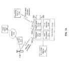
- FIG. 1Ais a diagram illustrating an exemplary wireless communication system, in accordance with an embodiment of the invention.
- an access point 112 bthere is shown an access point 112 b , a host device 110 a , a local data source 113 , a receiving device 114 a , a router 130 , the Internet 132 and a web server 134 .
- the host device 110 aor computer, for example, may comprise a wireless radio 111 a , a short-range radio 111 b , a host processor 111 c , and a host memory 111 d , and a plurality of antennas 120 A- 120 E.
- There is also shown a wireless connection between the wireless radio 111 a and the access point 112 bThere is also shown a wireless connection between the wireless radio 111 a and the access point 112 b , and a short-range wireless connection between the short-range radio 111 b and the receiving device 114 a.
- the host device 110 amay comprise a computer or set-top box device, for example, that may be operable to receive signals from data sources, process the received data, and communicate the processed data to receiving devices. Accordingly, the host device 110 a may comprise processors, such as the host processor 111 c , storage devices such as the host memory 111 d , and communication devices, such as the wireless radio 111 a and the short range radio 111 b.
- processorssuch as the host processor 111 c
- storage devicessuch as the host memory 111 d
- communication devicessuch as the wireless radio 111 a and the short range radio 111 b.
- the wireless radio 111 amay comprise suitable circuitry, logic, interfaces, and/or code that may be operable to communicate wireless signals to between the host device 110 a and external devices, such as the access point 112 b , for example. Accordingly, the wireless radio 111 a may comprise amplifiers, mixers, analog-to-digital and digital-to-analog converters, phase-locked loops, and clock sources, for example, that enable the communication of wireless signals.
- the short-range radio 111 bmay comprise suitable circuitry, logic, interfaces, and/or code that may be operable to communicate wireless signals over short distances. Accordingly, the frequency of transmission/reception may be in the 60 GHz range, which may enable short-range communications due to the attenuation of signals in air at this frequency. Similarly, the short-range radio 111 b may comprise amplifiers, mixers, analog-to-digital and digital-to-analog converters, phase-locked loops, and clock sources, for example, that enable the communication of wireless signals.
- the host processor 111 cmay comprise suitable circuitry, logic, interfaces, and/or code that may be operable to received control and/or data information, which may comprise programmable parameters, to determine an operating mode of the wireless radio 111 a and the short-range radio 111 b .
- the host processor 111 cmay be utilized to select a specific frequency for a local oscillator, a specific gain for a variable gain amplifier, configure the local oscillator and/or configure the variable gain amplifier for operation in accordance with various embodiments of the invention.
- the specific frequency selected and/or parameters needed to calculate the specific frequency, and/or the specific gain value and/or the parameters, which may be utilized to calculate the specific gainmay be stored in the host memory 111 d via the host processor 111 c , for example.
- the information stored in host memory 111 dmay be transferred to the wireless radio 111 a and/or the short-range radio 111 b from the host memory 111 d via the host processor 111 c.
- the host memory 111 dmay comprise suitable circuitry, logic, interfaces, and/or code that may be enabled to store a plurality of control and/or data information, including parameters needed to calculate frequencies and/or gain, and/or the frequency value and/or gain value.
- the host memory 111 dmay store at least a portion of the programmable parameters that may be manipulated by the host processor 111 c.
- the access point 112 bmay comprise suitable circuitry, logic, interfaces, and/or code that may be enabled to provide wireless signals to one or more devices within its range.
- the access point 112 bmay be coupled to the router 130 , thereby enabling connection to the Internet for devices that are operable to communicate with the access point 112 b.
- the local data source 113may comprise suitable circuitry, logic, interfaces, and/or code that may be enabled to communicate data to the host device 110 a .
- the local data sourcemay comprise a DVD player, and MP3 player, and/or a set-top box.
- the receiving device 114 Amay comprise suitable circuitry, logic, interfaces, and/or code that may be enabled to receive data communicated by the host device 110 a via the short-range radio 111 b .
- the receiving device 114 Amay comprise an HDTV that may be operable to display HD video signals and playback associated audio signals.
- the antennas 120 A- 120 Emay comprise suitable circuitry, logic, interfaces, and/or code that may be operable to transmit and/or receive wireless signals.
- the antenna 120 Amay be operable to transmit and receive wireless signals between the access point 112 b and the wireless radio 111 a
- the antennas 120 B- 120 Emay be operable to communicate signals between the short range radio 111 b and one or more external devices, such as the receiving devices 114 A.
- the router 130may comprise suitable circuitry, logic, interfaces, and/or code that may be enabled to communicate signals between the access point 112 b and the Internet. In this manner, devices within range of the access point 112 b may be enabled to connect to the Internet.
- the web server 134may comprise a remote server that may be operable to store content that may be accessed by the host device 110 a via the Internet 132 .
- the web server 134may comprise a movie provider server and may be operable to communicate a desired movie to the host device 110 a via the Internet for display via the receiving device 114 A.
- computing and communication devicesmay comprise hardware and software to communicate using multiple wireless communication standards.
- the wireless radio 111 amay be compliant with a mobile communications standard, for example.
- the wireless radio 111 a and the short-range radio 111 bmay be active concurrently.
- the usermay establish a wireless connection between the host device 110 a and the access point 112 b . Once this connection is established, the streaming content from the Web server 134 may be received via the router 130 , the access point 112 b , and the wireless connection, and consumed by the computer or host device 110 a.
- the user of the host device 110 amay communicate the streaming content to the receiving device 114 a , which may comprise a TV or other type of display, for example. Accordingly, the user of the host device 110 a may establish a short-range wireless connection with the receiving device 114 a . Once the short-range wireless connection is established, and with suitable configurations on the computer enabled, the streaming content may be displayed by the receiving device 114 a .
- the radio frequency (RF) generationmay support fast-switching to enable support of multiple communication standards and/or advanced wideband systems like, for example, Ultrawideband (UWB) radio.
- UWBUltrawideband
- W-HDTVwireless High-Definition TV
- UWBUser Datagram Bus
- 60-GHz communicationsOther applications of short-range communications may be wireless High-Definition TV (W-HDTV), from a set top box to a video display, for example.
- W-HDTVmay require high data rates that may be achieved with large bandwidth communication technologies, for example UWB and/or 60-GHz communications.
- the local data source 113may be operable to provide data to be displayed by the receiving device 114 a via the host device 110 a .
- the local data sourcemay comprise a DVD player or a digital video recorder.
- the local data sourcemay communicate with the host device 110 a via a wired connection or via a wireless connection, either directly with the host device 110 a or via the access point 112 b.
- the short range radio 111 bmay comprise a plurality of antennas 120 b - 120 E and frequency up-conversion devices throughout the host device 110 a for communicating high frequency RF signals.
- the short range radio 111 bmay comprise a baseband and IF stage with a single high power PA that may communicate IF signals over thin coaxial lines. Taps may be configured to couple the IF signals from the coaxial lines to the frequency up-conversion devices before being communicated to the plurality of antennas.
- IF signalsmay be amplified by a single PA and subsequently up-converted to 60 GHz, for example, for transmission via a plurality of antennas 120 B- 120 E without the need for multiple PAs with excessive power requirements.
- the inventionis not limited to the number of antennas shown in FIG. 1A . Accordingly, any number of antennas may be integrated in the host device 110 a , depending on space limitations and desired RF transmission directionality.
- FIG. 1Bis a block diagram illustrating a laptop computer with an exemplary 60 GHz distributed communication system, in accordance with an embodiment of the invention.
- a laptop computercomprising a display 121 , keyboard 123 , and a plurality of antennas 120 A- 120 M.
- the antennas 120 A- 120 Mmay be substantially similar to the antennas 120 A- 120 E described with respect to FIG. 1A , and may comprise antennas coupled to a plurality of remote RF devices throughout the laptop 150 . In this manner, one or more antenna configurations may be enabled, depending on the location of the receiving device, such as the receiving device 114 A, and the antenna configuration that results in the greatest signal strength, lowest bit error rate, highest data throughput, lowest latency, and/or the optimum of any other desired wireless communication characteristic.
- the antennas 120 A- 120 Mmay be coupled to remote RF devices throughout the laptop 150 .
- the remote RF devicesmay receive IF signals from a baseband and IF module via thin coaxial lines, described with respect to FIG. 2 , and may be operable to up-convert received IF signals to RF signals. In this manner, lower frequency signals may be communicated throughout the laptop 150 to the antennas that result in desired signal quality. This may enable a single high-power PA stage that amplifies the IF signals that are then up-converted to RF in the remote RF modules.
- a short-range wireless communication channelmay be enabled between the laptop 150 and the receiving device 114 A.
- a plurality of antenna configurationsmay be assessed for a desired performance characteristic, such as signal strength, bit error rate, data throughput, and/or latency, for example.
- the remote RF device configuration with the resulting desired performancemay then be enabled to receive IF signals via coaxial lines from a centrally located baseband and IF module, and up-convert the signals to RF before transmitting via the appropriate antennas 120 A- 120 M.
- short-range communicationsmay be enabled to one or more devices independent of its location in proximity with the laptop 150 .
- the frequency of the communicated signalsmay be different for different enabled antennas 120 A- 120 M, thereby allowing a plurality of signals to be transmitted concurrently.
- a plurality of IF signalsmay be communicated via coaxial lines to a plurality of remote RF devices, which may up-convert the IF signals to different RF frequencies, or subbands, for transmission.
- These subbandsmay be reused in different geographic locations ti mitigate the effect on co-channel interference. For example, if a certain location has RF interference in one of the subbands, other frequencies may be utilized.
- the laptop 150may store the frequency of blocker or other interference signals based on the location of the laptop, as determined by GPS, for example.
- FIG. 2is a block diagram illustrating an exemplary 60 GHz communication system, in accordance with an embodiment of the invention. Referring to FIG. 2 , there is shown a baseband and IF module 201 , RF devices 203 A- 203 H, taps 205 A- 205 H, and thin coaxial line 207 .
- the baseband and IF module 201may comprise suitable circuitry, logic, interfaces, and/or code that may be operable to generate IF signals comprising baseband data.
- the baseband and IF module 201may comprise one or more processors, such as a baseband processor, memory, and frequency conversion devices, for example.
- the processor or processors in the baseband and IF module 201may be any suitable processor or controller such as a CPU, DSP, ARM, or any type of integrated circuit processor, and may be enabled to update and/or modify programmable parameters and/or values in a plurality of components, devices, and/or processing elements in the baseband and IF module 201 .
- At least a portion of the programmable parametersmay be stored in memory, such as the host memory 111 d , for example, or dedicated memory in the baseband and IF module 201 .
- the RF devices 203 A- 203 Hmay comprise suitable circuitry, logic, interfaces, and/or code that may be operable to convert received IF signals to RF frequencies and transmit the RF signals via one or more antennas.
- the RF devices 203 A- 203 Hmay be configured remotely throughout a wireless communication device, such as the host device 110 a , described with respect to FIG. 1 , so that 60 GHz signals may be communicated from a plurality of directions, depending on the location of a device that is the intended receiving device.
- IF signalsmay be communicated from a single high power PA in the baseband and IF module 201 via the thin coaxial line 207 .
- the taps 205 A- 205 Hmay comprise suitable circuitry, logic, interfaces, and/or code that may be operable to couple a portion of the IF signal being communicated via the thin coaxial line 207 to the associated RF devices 203 A- 203 H. In this manner, taps may be configured to couple signals when it may be desired to transmit RF signals via one or more of the RF devices 203 A- 203 H.
- the thin coaxial line 207may comprise coaxial conductors separated by a dielectric material, for example, and may be operable to communicate IF signals throughout a device, such as the host device 110 a .
- the thin coaxial line 207may be operable to provide DC power for various devices within the host device 110 a , such as the RF devices 203 A- 203 H.
- the baseband and IF module 201may process baseband signals for transmission via the RF devices 203 A- 203 H.
- the baseband signalsmay be up-converted to IF and amplified by a PA prior to communication via the thin coaxial line 207 , which may distribute the IF signals throughout the device, such as the host device 110 a , for example.
- One or more of the taps 205 A- 205 Hmay be enabled to tap a portion of the communicated IF signals to associated RF devices 203 A- 203 H.
- the RF devices 203 A- 203 Hmay up-convert the tapped IF signals to RF frequencies, such as 60 GHz, for example, before transmission via one or more antennas in the RF devices 203 A- 203 H.
- an RF power amplifieris not required at each RF device 203 A- 203 H, which would require more power than by utilizing a single PA, such as the PA 201 A, at the IF stage in the baseband and IF module 201 .
- the thin coaxial line 207may communicate low frequency control signals to the RF devices 203 A- 203 H and the taps 205 A- 205 H.
- the control signalsmay be utilized to configure which of the taps 205 A- 205 H may be activated to tap off part of the IF signals for transmission by the appropriate RF device 202 A- 203 H.
- the control signalsmay be utilized to configure the up-conversion performed in the RF devices 203 A- 203 H. In this manner, only those RF devices 203 A- 203 H that have antennas in an appropriate direction for a desired receiving device may be activated, further reducing power requirements.
- FIG. 3is a block diagram illustrating an exemplary RF device, in accordance with an embodiment of the invention.
- a tap 305there is shown a tap 305 , a coaxial line 307 and an RF device 300 comprising a mixer 301 , a plurality of antennas 303 A- 303 D, and high-pass filter 309 .
- the antennas 303 A- 303 Emay be operable to transmit and/or receive RF signals.
- the tap 305 and the coaxial line 307may be substantially similar to the taps 205 A- 205 H and the coaxial line 207 described with respect to FIG. 2 .
- the mixer 301may comprise suitable circuitry, logic, interfaces, and/or code that may be operable to frequency shift a received input signal.
- the mixer 301may receive an IF input signal and generate an RF output signal.
- the mixer 301may also receive as an input signal, an LO signal that may be utilized to up-convert the received IF signal to RF frequencies.
- the high-pass filter 309may comprise suitable circuitry, logic, interfaces, and/or code that may be operable to attenuate low-frequency signals, defined as signals below a configurable corner frequency, and allow frequencies above the corner frequency to pass. For example, if sum and difference signals are generated by the mixer 301 based on the LO signal and received IF signal, the high-pass filter 309 may allow only the high frequency RF signal to pass to the antennas 303 A- 303 E.
- control signals in the coaxial line 307may configure the tap 305 to tap off a portion of an IF signal communicated via the coaxial line 307 and communicate it to the mixer 301 .
- the LO signalmay be utilized to up-convert the IF signal to RF frequencies, and the high-pass filter 309 may filter out all but the desired signal at a frequency above a configurable corner frequency of the high-pass filter 309 .
- the filtered RF signalmay then be communicated to one or more antennas of the antennas 303 A- 303 E.
- the control signalsmay also be utilized to configure the frequency of the LO signal, thereby configuring the frequency of the RF signal to be communicated.
- FIG. 4is a block diagram illustrating exemplary steps in 60 GHz distributed communication, in accordance with an embodiment of the invention.
- the baseband and IF modulegenerates an IF signal utilizing baseband processed data to be transmitted.
- the generated IF signalmay be communicated via thin coaxial line.
- the IF signalmay be tapped off by one or more taps and up-converted to RF.
- the RF signalsmay be transmitted by one or more antennas, followed by end step 411 .
- a method and systemmay comprise generating IF signals from baseband signals in a wireless communication device 110 a with wireless capability.
- the generated IF signalsmay be communicated to a plurality of remote RF modules 203 A- 203 H, within the communication device 110 a via one or more coaxial lines 207 , 307 .
- the remote RF modules 203 A- 203 Hmay be configured by a processor 111 c in the wireless communication device 110 a .
- the IF signalsmay be up-converted to RF signals in one or more of the remote RF modules 203 A- 203 H, and the RF signals may be transmitted via one or more antennas 303 in the remote RF modules 203 A- 203 H.
- the IF signalsmay be amplified by a power amplifier prior to being communicated via the coaxial lines.
- the IF signals in the coaxial lines 207 , 307may be tapped via taps 205 A- 205 H, 305 coupled to the plurality of remote RF modules 203 A- 203 H.
- the baseband signalsmay comprise video data, streamed Internet data, and/or data from a local data source 113 .
- the RF signalsmay be communicated to a display device. Control signals for the plurality of remote RF devices 203 A- 203 H, may be communicated utilizing the coaxial lines 207 , 307 .
- One or more of the plurality of remote RF devices 203 A- 203 Hmay be selected based on a direction to a receiving device 114 A for the transmitted RF signals.
- the plurality of remote RF devices 203 A- 203 Hmay comprise mixers.
- the RF signalsmay comprise 60 GHz signals.
- inventionsmay provide a non-transitory computer readable medium and/or storage medium, and/or a non-transitory machine readable medium and/or storage medium, having stored thereon, a machine code and/or a computer program having at least one code section executable by a machine and/or a computer, thereby causing the machine and/or computer to perform the steps as described herein for 60 GHz distributed communication.
- aspects of the inventionmay be realized in hardware, software, firmware or a combination thereof.
- the inventionmay be realized in a centralized fashion in at least one computer system or in a distributed fashion where different elements are spread across several interconnected computer systems. Any kind of computer system or other apparatus adapted for carrying out the methods described herein is suited.
- a typical combination of hardware, software and firmwaremay be a general-purpose computer system with a computer program that, when being loaded and executed, controls the computer system such that it carries out the methods described herein.
- One embodiment of the present inventionmay be implemented as a board level product, as a single chip, application specific integrated circuit (ASIC), or with varying levels integrated on a single chip with other portions of the system as separate components.
- the degree of integration of the systemwill primarily be determined by speed and cost considerations. Because of the sophisticated nature of modern processors, it is possible to utilize a commercially available processor, which may be implemented external to an ASIC implementation of the present system. Alternatively, if the processor is available as an ASIC core or logic block, then the commercially available processor may be implemented as part of an ASIC device with various functions implemented as firmware.
- the present inventionmay also be embedded in a computer program product, which comprises all the features enabling the implementation of the methods described herein, and which when loaded in a computer system is able to carry out these methods.
- Computer program in the present contextmay mean, for example, any expression, in any language, code or notation, of a set of instructions intended to cause a system having an information processing capability to perform a particular function either directly or after either or both of the following: a) conversion to another language, code or notation; b) reproduction in a different material form.
- other meanings of computer programwithin the understanding of those skilled in the art are also contemplated by the present invention.
Landscapes
- Engineering & Computer Science (AREA)
- Computer Networks & Wireless Communication (AREA)
- Signal Processing (AREA)
- Mobile Radio Communication Systems (AREA)
- Transceivers (AREA)
Abstract
Description
Claims (18)
Priority Applications (1)
| Application Number | Priority Date | Filing Date | Title |
|---|---|---|---|
| US14/638,711US9608674B2 (en) | 2010-09-30 | 2015-03-04 | Method and system for 60 GHz distributed communication |
Applications Claiming Priority (8)
| Application Number | Priority Date | Filing Date | Title |
|---|---|---|---|
| US12/895,547US8913951B2 (en) | 2007-09-30 | 2010-09-30 | Method and system for 60 GHz distributed communication utilizing a mesh network of repeaters |
| US12/895,514US9008593B2 (en) | 2010-09-30 | 2010-09-30 | Method and system for 60 GHz distributed communication |
| US12/895,520US8977219B2 (en) | 2010-09-30 | 2010-09-30 | Method and system for mitigating leakage of a 60 GHz transmitted signal back into an RF input of a 60 GHz device |
| US12/895,503US8942645B2 (en) | 2010-09-30 | 2010-09-30 | Method and system for communication via subbands in a 60 GHZ distributed communication system |
| US12/895,528US8942646B2 (en) | 2010-09-30 | 2010-09-30 | Method and system for a 60 GHz communication device comprising multi-location antennas for pseudo-beamforming |
| US12/895,537US8942647B2 (en) | 2010-09-30 | 2010-09-30 | Method and system for antenna switching for 60 GHz distributed communication |
| US12/895,573US9002300B2 (en) | 2010-09-30 | 2010-09-30 | Method and system for time division duplexing (TDD) in a 60 GHZ distributed communication system |
| US14/638,711US9608674B2 (en) | 2010-09-30 | 2015-03-04 | Method and system for 60 GHz distributed communication |
Related Parent Applications (1)
| Application Number | Title | Priority Date | Filing Date |
|---|---|---|---|
| US12/895,514ContinuationUS9008593B2 (en) | 2007-09-30 | 2010-09-30 | Method and system for 60 GHz distributed communication |
Publications (2)
| Publication Number | Publication Date |
|---|---|
| US20150180515A1 US20150180515A1 (en) | 2015-06-25 |
| US9608674B2true US9608674B2 (en) | 2017-03-28 |
Family
ID=44799484
Family Applications (2)
| Application Number | Title | Priority Date | Filing Date |
|---|---|---|---|
| US12/895,514Expired - Fee RelatedUS9008593B2 (en) | 2007-09-30 | 2010-09-30 | Method and system for 60 GHz distributed communication |
| US14/638,711Active2030-11-02US9608674B2 (en) | 2010-09-30 | 2015-03-04 | Method and system for 60 GHz distributed communication |
Family Applications Before (1)
| Application Number | Title | Priority Date | Filing Date |
|---|---|---|---|
| US12/895,514Expired - Fee RelatedUS9008593B2 (en) | 2007-09-30 | 2010-09-30 | Method and system for 60 GHz distributed communication |
Country Status (5)
| Country | Link |
|---|---|
| US (2) | US9008593B2 (en) |
| EP (1) | EP2437571B1 (en) |
| KR (1) | KR101316800B1 (en) |
| CN (1) | CN102447508A (en) |
| TW (1) | TWI542176B (en) |
Families Citing this family (18)
| Publication number | Priority date | Publication date | Assignee | Title |
|---|---|---|---|---|
| US8913951B2 (en)* | 2007-09-30 | 2014-12-16 | Broadcom Corporation | Method and system for 60 GHz distributed communication utilizing a mesh network of repeaters |
| US9118217B2 (en)* | 2010-09-30 | 2015-08-25 | Broadcom Corporation | Portable computing device with wireless power distribution |
| US9037094B2 (en) | 2011-10-17 | 2015-05-19 | Golba Llc | Method and system for high-throughput and low-power communication links in a distributed transceiver network |
| US9197982B2 (en) | 2012-08-08 | 2015-11-24 | Golba Llc | Method and system for distributed transceivers for distributed access points connectivity |
| US10321332B2 (en) | 2017-05-30 | 2019-06-11 | Movandi Corporation | Non-line-of-sight (NLOS) coverage for millimeter wave communication |
| US10484078B2 (en) | 2017-07-11 | 2019-11-19 | Movandi Corporation | Reconfigurable and modular active repeater device |
| US10348371B2 (en) | 2017-12-07 | 2019-07-09 | Movandi Corporation | Optimized multi-beam antenna array network with an extended radio frequency range |
| US10862559B2 (en) | 2017-12-08 | 2020-12-08 | Movandi Corporation | Signal cancellation in radio frequency (RF) device network |
| US10090887B1 (en) | 2017-12-08 | 2018-10-02 | Movandi Corporation | Controlled power transmission in radio frequency (RF) device network |
| US10637159B2 (en) | 2018-02-26 | 2020-04-28 | Movandi Corporation | Waveguide antenna element-based beam forming phased array antenna system for millimeter wave communication |
| US11088457B2 (en) | 2018-02-26 | 2021-08-10 | Silicon Valley Bank | Waveguide antenna element based beam forming phased array antenna system for millimeter wave communication |
| US11716558B2 (en) | 2018-04-16 | 2023-08-01 | Charter Communications Operating, Llc | Apparatus and methods for integrated high-capacity data and wireless network services |
| US10911552B1 (en) | 2018-07-31 | 2021-02-02 | Apple Inc. | Shared access to computing resources using wireless communications |
| WO2020077346A1 (en) | 2018-10-12 | 2020-04-16 | Charter Communications Operating, Llc | Apparatus and methods for cell identification in wireless networks |
| US11843474B2 (en) | 2020-02-11 | 2023-12-12 | Charter Communications Operating, Llc | Apparatus and methods for providing high-capacity data services over a content delivery network |
| US11985641B2 (en) | 2020-04-22 | 2024-05-14 | Charter Communications Operating, Llc | Node apparatus and methods for providing high-capacity data services via a content delivery network architecture |
| US11570015B2 (en) | 2020-04-22 | 2023-01-31 | Charter Communications Operating, Llc | Premises apparatus and methods for aggregated high-capacity data services |
| US11612009B2 (en) | 2020-07-31 | 2023-03-21 | Charter Communications Operating, Llc | Apparatus and methods for operating multi-link devices in wireless networks |
Citations (43)
| Publication number | Priority date | Publication date | Assignee | Title |
|---|---|---|---|---|
| US5280472A (en) | 1990-12-07 | 1994-01-18 | Qualcomm Incorporated | CDMA microcellular telephone system and distributed antenna system therefor |
| US5379455A (en) | 1991-02-28 | 1995-01-03 | Hewlett-Packard Company | Modular distributed antenna system |
| US5461646A (en) | 1993-12-29 | 1995-10-24 | Tcsi Corporation | Synchronization apparatus for a diversity receiver |
| EP0685973A2 (en) | 1994-06-03 | 1995-12-06 | AT&T Corp. | Radio-parts assignment in a mobile cellular communication system |
| US5533011A (en) | 1990-12-07 | 1996-07-02 | Qualcomm Incorporated | Dual distributed antenna system |
| US5781847A (en) | 1994-09-10 | 1998-07-14 | U.S. Philips Corporation | Microwave transmitter and communications system |
| US5802173A (en) | 1991-01-15 | 1998-09-01 | Rogers Cable Systems Limited | Radiotelephony system |
| US5805983A (en) | 1996-07-18 | 1998-09-08 | Ericsson Inc. | System and method for equalizing the delay time for transmission paths in a distributed antenna network |
| US5901144A (en) | 1995-04-13 | 1999-05-04 | Hitachi, Ltd. | Mobile radio communications system |
| US5969837A (en) | 1996-12-15 | 1999-10-19 | Foxcom Wireless Ltd. | Communications system |
| US6023458A (en) | 1998-01-26 | 2000-02-08 | Gte Laboratories Incorporated | Method and system for distributing subscriber services using wireless bidirectional broadband loops |
| US6070063A (en) | 1995-08-31 | 2000-05-30 | Sony Corporation | Transmitting apparatus and method of adjusting gain of signal to be transmitted, and receiving apparatus and method of adjusting gain of received signal |
| US6078622A (en) | 1997-12-22 | 2000-06-20 | Delco Electronics Corporation | Distributed digital radio system |
| GB2354674A (en) | 1999-08-23 | 2001-03-28 | Samsung Electronics Co Ltd | Distributed architecture for a base station transceiver subsystem with remotely programmable radio unit |
| US20010046840A1 (en) | 2000-05-24 | 2001-11-29 | Kyung-Hwan Kim | Apparatus for transmitting and receiving radio signals in a pico-BTS |
| US6405018B1 (en) | 1999-01-11 | 2002-06-11 | Metawave Communications Corporation | Indoor distributed microcell |
| US6449477B1 (en) | 2000-04-25 | 2002-09-10 | Qualcomm, Incorporated | Radio frequency coverage of an enclosed region by arrangement of transceivers within the region |
| US20030045284A1 (en) | 2001-09-05 | 2003-03-06 | Copley Richard T. | Wireless communication system, apparatus and method for providing communication service using an additional frequency band through an in-building communication infrastructure |
| US20030207668A1 (en)* | 2002-05-03 | 2003-11-06 | Mcfarland William J. | Dual frequency band wireless lan |
| US20040051598A1 (en) | 2002-09-13 | 2004-03-18 | Stratex Networks, Inc. | Method and apparatus for re-modulation using zero if |
| US6801767B1 (en) | 2001-01-26 | 2004-10-05 | Lgc Wireless, Inc. | Method and system for distributing multiband wireless communications signals |
| US20060253872A1 (en) | 2003-02-28 | 2006-11-09 | Yozo Shoji | Wireless communication system |
| US20070218845A1 (en) | 2004-03-26 | 2007-09-20 | Broadcom Corporation, A California Corporation | Shared antenna control |
| US20070224931A1 (en) | 2003-02-14 | 2007-09-27 | Kabushiki Kaisha Toshiba | Communication network for indoor environment |
| US20070280370A1 (en) | 2004-04-14 | 2007-12-06 | Sheng Liu | Multiple input/multiple output communication method based on distributed transmission sources |
| US20080014948A1 (en) | 2006-07-14 | 2008-01-17 | Lgc Wireless, Inc. | System for and method of for providing dedicated capacity in a cellular network |
| WO2008027213A2 (en) | 2006-08-29 | 2008-03-06 | Lgc Wireless, Inc. | Distributed antenna communications system and methods of implementing thereof |
| US7426231B1 (en) | 2000-06-19 | 2008-09-16 | Bertrand Dorfman | Communication within buildings |
| US7460082B2 (en) | 2003-12-30 | 2008-12-02 | Intel Corporation | Sectored antenna systems for WLAN |
| US20090061940A1 (en) | 2007-08-31 | 2009-03-05 | Stefan Scheinert | System for and method of configuring distributed antenna communications system |
| US7561904B2 (en) | 2005-10-26 | 2009-07-14 | Hewlett-Packard Development Company, L.P. | Systems and methods for managing antenna use |
| US20090258652A1 (en) | 2001-05-02 | 2009-10-15 | Thomas Lambert | Cellular systems with distributed antennas |
| US20090316609A1 (en) | 2008-06-24 | 2009-12-24 | Lgc Wireless, Inc. | System and method for synchronized time-division duplex signal switching |
| US7640035B2 (en) | 2004-07-12 | 2009-12-29 | Samsung Electronics Co., Ltd. | Wireless home LAN system using multiple antennas |
| US20100087227A1 (en) | 2008-10-02 | 2010-04-08 | Alvarion Ltd. | Wireless base station design |
| US20100202557A1 (en) | 2009-02-10 | 2010-08-12 | Thales Holdings Uk Plc | Digital IF Distribution Networks for Radio Communications |
| US7787854B2 (en) | 2005-02-01 | 2010-08-31 | Adc Telecommunications, Inc. | Scalable distributed radio network |
| US20110063169A1 (en) | 2009-09-13 | 2011-03-17 | International Business Machines Corporation | Phased-array transceiver for millimeter-wave frequencies |
| US20110135013A1 (en) | 2008-05-21 | 2011-06-09 | Samplify Systems, Inc. | Compression of baseband signals in base transceiver systems |
| US20110141895A1 (en) | 2008-07-03 | 2011-06-16 | Zte Corporation | Hierarchical Wireless Access System and Access Point Management Unit in the System |
| US8005050B2 (en) | 2007-03-23 | 2011-08-23 | Lgc Wireless, Inc. | Localization of a mobile device in distributed antenna communications system |
| US8010116B2 (en) | 2007-06-26 | 2011-08-30 | Lgc Wireless, Inc. | Distributed antenna communications system |
| US8159399B2 (en) | 2008-06-03 | 2012-04-17 | Apple Inc. | Antenna diversity systems for portable electronic devices |
Family Cites Families (3)
| Publication number | Priority date | Publication date | Assignee | Title |
|---|---|---|---|---|
| CN1452401A (en)* | 2002-04-16 | 2003-10-29 | 宽频多媒体股份有限公司 | Set-top box signal input/output device and method |
| US7965837B2 (en)* | 2003-04-30 | 2011-06-21 | Sony Corporation | Method and system for wireless digital video presentation |
| CN100362752C (en)* | 2006-03-21 | 2008-01-16 | 东南大学 | Realization method and device of low-complexity ultra-wideband radio frequency front-end |
- 2010
- 2010-09-30USUS12/895,514patent/US9008593B2/ennot_activeExpired - Fee Related
- 2011
- 2011-09-26EPEP11007814.4Apatent/EP2437571B1/enactiveActive
- 2011-09-29TWTW100135212Apatent/TWI542176B/ennot_activeIP Right Cessation
- 2011-09-29CNCN2011103022297Apatent/CN102447508A/enactivePending
- 2011-09-30KRKR1020110100009Apatent/KR101316800B1/ennot_activeExpired - Fee Related
- 2015
- 2015-03-04USUS14/638,711patent/US9608674B2/enactiveActive
Patent Citations (46)
| Publication number | Priority date | Publication date | Assignee | Title |
|---|---|---|---|---|
| US5533011A (en) | 1990-12-07 | 1996-07-02 | Qualcomm Incorporated | Dual distributed antenna system |
| US5280472A (en) | 1990-12-07 | 1994-01-18 | Qualcomm Incorporated | CDMA microcellular telephone system and distributed antenna system therefor |
| US5802173A (en) | 1991-01-15 | 1998-09-01 | Rogers Cable Systems Limited | Radiotelephony system |
| US5379455A (en) | 1991-02-28 | 1995-01-03 | Hewlett-Packard Company | Modular distributed antenna system |
| US5461646A (en) | 1993-12-29 | 1995-10-24 | Tcsi Corporation | Synchronization apparatus for a diversity receiver |
| EP0685973A2 (en) | 1994-06-03 | 1995-12-06 | AT&T Corp. | Radio-parts assignment in a mobile cellular communication system |
| US5519691A (en) | 1994-06-03 | 1996-05-21 | At&T Corp. | Arrangement for and method of providing radio frequency access to a switching system |
| US5781847A (en) | 1994-09-10 | 1998-07-14 | U.S. Philips Corporation | Microwave transmitter and communications system |
| US5901144A (en) | 1995-04-13 | 1999-05-04 | Hitachi, Ltd. | Mobile radio communications system |
| US6070063A (en) | 1995-08-31 | 2000-05-30 | Sony Corporation | Transmitting apparatus and method of adjusting gain of signal to be transmitted, and receiving apparatus and method of adjusting gain of received signal |
| US5805983A (en) | 1996-07-18 | 1998-09-08 | Ericsson Inc. | System and method for equalizing the delay time for transmission paths in a distributed antenna network |
| US5969837A (en) | 1996-12-15 | 1999-10-19 | Foxcom Wireless Ltd. | Communications system |
| US6078622A (en) | 1997-12-22 | 2000-06-20 | Delco Electronics Corporation | Distributed digital radio system |
| US6023458A (en) | 1998-01-26 | 2000-02-08 | Gte Laboratories Incorporated | Method and system for distributing subscriber services using wireless bidirectional broadband loops |
| US6405018B1 (en) | 1999-01-11 | 2002-06-11 | Metawave Communications Corporation | Indoor distributed microcell |
| GB2354674A (en) | 1999-08-23 | 2001-03-28 | Samsung Electronics Co Ltd | Distributed architecture for a base station transceiver subsystem with remotely programmable radio unit |
| US6449477B1 (en) | 2000-04-25 | 2002-09-10 | Qualcomm, Incorporated | Radio frequency coverage of an enclosed region by arrangement of transceivers within the region |
| US20010046840A1 (en) | 2000-05-24 | 2001-11-29 | Kyung-Hwan Kim | Apparatus for transmitting and receiving radio signals in a pico-BTS |
| US7426231B1 (en) | 2000-06-19 | 2008-09-16 | Bertrand Dorfman | Communication within buildings |
| US6801767B1 (en) | 2001-01-26 | 2004-10-05 | Lgc Wireless, Inc. | Method and system for distributing multiband wireless communications signals |
| US20090258652A1 (en) | 2001-05-02 | 2009-10-15 | Thomas Lambert | Cellular systems with distributed antennas |
| US20030045284A1 (en) | 2001-09-05 | 2003-03-06 | Copley Richard T. | Wireless communication system, apparatus and method for providing communication service using an additional frequency band through an in-building communication infrastructure |
| US20030207668A1 (en)* | 2002-05-03 | 2003-11-06 | Mcfarland William J. | Dual frequency band wireless lan |
| US20040051598A1 (en) | 2002-09-13 | 2004-03-18 | Stratex Networks, Inc. | Method and apparatus for re-modulation using zero if |
| US20070224931A1 (en) | 2003-02-14 | 2007-09-27 | Kabushiki Kaisha Toshiba | Communication network for indoor environment |
| US20060253872A1 (en) | 2003-02-28 | 2006-11-09 | Yozo Shoji | Wireless communication system |
| US7460082B2 (en) | 2003-12-30 | 2008-12-02 | Intel Corporation | Sectored antenna systems for WLAN |
| US20070218845A1 (en) | 2004-03-26 | 2007-09-20 | Broadcom Corporation, A California Corporation | Shared antenna control |
| US20070280370A1 (en) | 2004-04-14 | 2007-12-06 | Sheng Liu | Multiple input/multiple output communication method based on distributed transmission sources |
| US7640035B2 (en) | 2004-07-12 | 2009-12-29 | Samsung Electronics Co., Ltd. | Wireless home LAN system using multiple antennas |
| US7787854B2 (en) | 2005-02-01 | 2010-08-31 | Adc Telecommunications, Inc. | Scalable distributed radio network |
| US7561904B2 (en) | 2005-10-26 | 2009-07-14 | Hewlett-Packard Development Company, L.P. | Systems and methods for managing antenna use |
| US20080014948A1 (en) | 2006-07-14 | 2008-01-17 | Lgc Wireless, Inc. | System for and method of for providing dedicated capacity in a cellular network |
| US20080058018A1 (en) | 2006-08-29 | 2008-03-06 | Lgc Wireless, Inc. | Distributed antenna communications system and methods of implementing thereof |
| WO2008027213A2 (en) | 2006-08-29 | 2008-03-06 | Lgc Wireless, Inc. | Distributed antenna communications system and methods of implementing thereof |
| JP2010503263A (en) | 2006-08-29 | 2010-01-28 | エルジーシー ワイヤレス,インコーポレイティド | Distributed antenna communication system and its implementation method |
| US8005050B2 (en) | 2007-03-23 | 2011-08-23 | Lgc Wireless, Inc. | Localization of a mobile device in distributed antenna communications system |
| US8010116B2 (en) | 2007-06-26 | 2011-08-30 | Lgc Wireless, Inc. | Distributed antenna communications system |
| US20090061940A1 (en) | 2007-08-31 | 2009-03-05 | Stefan Scheinert | System for and method of configuring distributed antenna communications system |
| US20110135013A1 (en) | 2008-05-21 | 2011-06-09 | Samplify Systems, Inc. | Compression of baseband signals in base transceiver systems |
| US8159399B2 (en) | 2008-06-03 | 2012-04-17 | Apple Inc. | Antenna diversity systems for portable electronic devices |
| US20090316609A1 (en) | 2008-06-24 | 2009-12-24 | Lgc Wireless, Inc. | System and method for synchronized time-division duplex signal switching |
| US20110141895A1 (en) | 2008-07-03 | 2011-06-16 | Zte Corporation | Hierarchical Wireless Access System and Access Point Management Unit in the System |
| US20100087227A1 (en) | 2008-10-02 | 2010-04-08 | Alvarion Ltd. | Wireless base station design |
| US20100202557A1 (en) | 2009-02-10 | 2010-08-12 | Thales Holdings Uk Plc | Digital IF Distribution Networks for Radio Communications |
| US20110063169A1 (en) | 2009-09-13 | 2011-03-17 | International Business Machines Corporation | Phased-array transceiver for millimeter-wave frequencies |
Non-Patent Citations (2)
| Title |
|---|
| Definition of term "Device" located at http://dictionary.reference.com/browse/device. |
| Definition of term "within" located at http://dictionary.reference.com/browse/within. |
Also Published As
| Publication number | Publication date |
|---|---|
| CN102447508A (en) | 2012-05-09 |
| EP2437571A1 (en) | 2012-04-04 |
| KR101316800B1 (en) | 2013-10-11 |
| EP2437571B1 (en) | 2016-08-03 |
| TWI542176B (en) | 2016-07-11 |
| KR20120034056A (en) | 2012-04-09 |
| US20150180515A1 (en) | 2015-06-25 |
| US20120083207A1 (en) | 2012-04-05 |
| US9008593B2 (en) | 2015-04-14 |
| TW201230739A (en) | 2012-07-16 |
Similar Documents
| Publication | Publication Date | Title |
|---|---|---|
| US9608674B2 (en) | Method and system for 60 GHz distributed communication | |
| US8913951B2 (en) | Method and system for 60 GHz distributed communication utilizing a mesh network of repeaters | |
| US8942647B2 (en) | Method and system for antenna switching for 60 GHz distributed communication | |
| US8942645B2 (en) | Method and system for communication via subbands in a 60 GHZ distributed communication system | |
| US8942646B2 (en) | Method and system for a 60 GHz communication device comprising multi-location antennas for pseudo-beamforming | |
| US8509356B2 (en) | Method and system for blocker and/or leakage signal rejection by DC bias cancellation | |
| US8295333B2 (en) | Method and system for inter-PCB communication utilizing a spatial multi-link repeater | |
| US8244175B2 (en) | Method and system for signal repeater with gain control and spatial isolation | |
| US8660168B2 (en) | Method and system for communicating via a spatial multilink repeater | |
| US9002300B2 (en) | Method and system for time division duplexing (TDD) in a 60 GHZ distributed communication system | |
| US20070049330A1 (en) | Wireless transceiver for supporting a plurality of communication or broadcasting services | |
| US20130301519A1 (en) | Wireless Clock Distribution | |
| US8977219B2 (en) | Method and system for mitigating leakage of a 60 GHz transmitted signal back into an RF input of a 60 GHz device | |
| US8514997B2 (en) | Method and system for a receiver with undersampling mixing using multiple clock phases | |
| US8750813B2 (en) | Method and system for a dynamic transmission gain control using a dedicated power amplifier driver in a radio frequency transmitter | |
| US8284704B2 (en) | Method and system for utilizing undersampling for crystal leakage cancellation | |
| HK1173571A (en) | Method and system for 60 ghz distributed communication | |
| HK1167945A (en) | Method and system for 60 ghz distributed communication | |
| US20090280751A1 (en) | Method And System For On-Demand Beamforming |
Legal Events
| Date | Code | Title | Description |
|---|---|---|---|
| AS | Assignment | Owner name:BROADCOM CORPORATION, CALIFORNIA Free format text:ASSIGNMENT OF ASSIGNORS INTEREST;ASSIGNORS:ROFOUGARAN, AHMADREZA;ROFOUGARAN, MARYAM;REEL/FRAME:035665/0961 Effective date:20100930 | |
| AS | Assignment | Owner name:BANK OF AMERICA, N.A., AS COLLATERAL AGENT, NORTH CAROLINA Free format text:PATENT SECURITY AGREEMENT;ASSIGNOR:BROADCOM CORPORATION;REEL/FRAME:037806/0001 Effective date:20160201 Owner name:BANK OF AMERICA, N.A., AS COLLATERAL AGENT, NORTH Free format text:PATENT SECURITY AGREEMENT;ASSIGNOR:BROADCOM CORPORATION;REEL/FRAME:037806/0001 Effective date:20160201 | |
| AS | Assignment | Owner name:AVAGO TECHNOLOGIES GENERAL IP (SINGAPORE) PTE. LTD., SINGAPORE Free format text:ASSIGNMENT OF ASSIGNORS INTEREST;ASSIGNOR:BROADCOM CORPORATION;REEL/FRAME:041706/0001 Effective date:20170120 Owner name:AVAGO TECHNOLOGIES GENERAL IP (SINGAPORE) PTE. LTD Free format text:ASSIGNMENT OF ASSIGNORS INTEREST;ASSIGNOR:BROADCOM CORPORATION;REEL/FRAME:041706/0001 Effective date:20170120 | |
| AS | Assignment | Owner name:BROADCOM CORPORATION, CALIFORNIA Free format text:TERMINATION AND RELEASE OF SECURITY INTEREST IN PATENTS;ASSIGNOR:BANK OF AMERICA, N.A., AS COLLATERAL AGENT;REEL/FRAME:041712/0001 Effective date:20170119 | |
| STCF | Information on status: patent grant | Free format text:PATENTED CASE | |
| AS | Assignment | Owner name:AVAGO TECHNOLOGIES INTERNATIONAL SALES PTE. LIMITE Free format text:MERGER;ASSIGNOR:AVAGO TECHNOLOGIES GENERAL IP (SINGAPORE) PTE. LTD.;REEL/FRAME:047422/0464 Effective date:20180509 | |
| AS | Assignment | Owner name:AVAGO TECHNOLOGIES INTERNATIONAL SALES PTE. LIMITE Free format text:CORRECTIVE ASSIGNMENT TO CORRECT THE EXECUTION DATE PREVIOUSLY RECORDED AT REEL: 047422 FRAME: 0464. ASSIGNOR(S) HEREBY CONFIRMS THE MERGER;ASSIGNOR:AVAGO TECHNOLOGIES GENERAL IP (SINGAPORE) PTE. LTD.;REEL/FRAME:048883/0702 Effective date:20180905 | |
| MAFP | Maintenance fee payment | Free format text:PAYMENT OF MAINTENANCE FEE, 4TH YEAR, LARGE ENTITY (ORIGINAL EVENT CODE: M1551); ENTITY STATUS OF PATENT OWNER: LARGE ENTITY Year of fee payment:4 | |
| MAFP | Maintenance fee payment | Free format text:PAYMENT OF MAINTENANCE FEE, 8TH YEAR, LARGE ENTITY (ORIGINAL EVENT CODE: M1552); ENTITY STATUS OF PATENT OWNER: LARGE ENTITY Year of fee payment:8 |