US9607239B2 - Articulated arm coordinate measurement machine having a 2D camera and method of obtaining 3D representations - Google Patents
Articulated arm coordinate measurement machine having a 2D camera and method of obtaining 3D representationsDownload PDFInfo
- Publication number
- US9607239B2 US9607239B2US14/485,876US201414485876AUS9607239B2US 9607239 B2US9607239 B2US 9607239B2US 201414485876 AUS201414485876 AUS 201414485876AUS 9607239 B2US9607239 B2US 9607239B2
- Authority
- US
- United States
- Prior art keywords
- pattern
- camera
- light
- edge
- aacmm
- Prior art date
- Legal status (The legal status is an assumption and is not a legal conclusion. Google has not performed a legal analysis and makes no representation as to the accuracy of the status listed.)
- Expired - Fee Related, expires
Links
Images


Classifications
- G06K9/4604—
- H—ELECTRICITY
- H04—ELECTRIC COMMUNICATION TECHNIQUE
- H04N—PICTORIAL COMMUNICATION, e.g. TELEVISION
- H04N13/00—Stereoscopic video systems; Multi-view video systems; Details thereof
- H04N13/20—Image signal generators
- H04N13/204—Image signal generators using stereoscopic image cameras
- H04N13/239—Image signal generators using stereoscopic image cameras using two 2D image sensors having a relative position equal to or related to the interocular distance
- G—PHYSICS
- G01—MEASURING; TESTING
- G01B—MEASURING LENGTH, THICKNESS OR SIMILAR LINEAR DIMENSIONS; MEASURING ANGLES; MEASURING AREAS; MEASURING IRREGULARITIES OF SURFACES OR CONTOURS
- G01B11/00—Measuring arrangements characterised by the use of optical techniques
- G01B11/002—Measuring arrangements characterised by the use of optical techniques for measuring two or more coordinates
- G01B11/005—Measuring arrangements characterised by the use of optical techniques for measuring two or more coordinates coordinate measuring machines
- G—PHYSICS
- G01—MEASURING; TESTING
- G01B—MEASURING LENGTH, THICKNESS OR SIMILAR LINEAR DIMENSIONS; MEASURING ANGLES; MEASURING AREAS; MEASURING IRREGULARITIES OF SURFACES OR CONTOURS
- G01B11/00—Measuring arrangements characterised by the use of optical techniques
- G01B11/24—Measuring arrangements characterised by the use of optical techniques for measuring contours or curvatures
- G01B11/25—Measuring arrangements characterised by the use of optical techniques for measuring contours or curvatures by projecting a pattern, e.g. one or more lines, moiré fringes on the object
- G01B11/2509—Color coding
- G—PHYSICS
- G01—MEASURING; TESTING
- G01B—MEASURING LENGTH, THICKNESS OR SIMILAR LINEAR DIMENSIONS; MEASURING ANGLES; MEASURING AREAS; MEASURING IRREGULARITIES OF SURFACES OR CONTOURS
- G01B11/00—Measuring arrangements characterised by the use of optical techniques
- G01B11/24—Measuring arrangements characterised by the use of optical techniques for measuring contours or curvatures
- G01B11/25—Measuring arrangements characterised by the use of optical techniques for measuring contours or curvatures by projecting a pattern, e.g. one or more lines, moiré fringes on the object
- G01B11/2513—Measuring arrangements characterised by the use of optical techniques for measuring contours or curvatures by projecting a pattern, e.g. one or more lines, moiré fringes on the object with several lines being projected in more than one direction, e.g. grids, patterns
- G—PHYSICS
- G01—MEASURING; TESTING
- G01B—MEASURING LENGTH, THICKNESS OR SIMILAR LINEAR DIMENSIONS; MEASURING ANGLES; MEASURING AREAS; MEASURING IRREGULARITIES OF SURFACES OR CONTOURS
- G01B21/00—Measuring arrangements or details thereof, where the measuring technique is not covered by the other groups of this subclass, unspecified or not relevant
- G01B21/02—Measuring arrangements or details thereof, where the measuring technique is not covered by the other groups of this subclass, unspecified or not relevant for measuring length, width, or thickness
- G01B21/04—Measuring arrangements or details thereof, where the measuring technique is not covered by the other groups of this subclass, unspecified or not relevant for measuring length, width, or thickness by measuring coordinates of points
- G01B21/047—Accessories, e.g. for positioning, for tool-setting, for measuring probes
- G—PHYSICS
- G01—MEASURING; TESTING
- G01B—MEASURING LENGTH, THICKNESS OR SIMILAR LINEAR DIMENSIONS; MEASURING ANGLES; MEASURING AREAS; MEASURING IRREGULARITIES OF SURFACES OR CONTOURS
- G01B5/00—Measuring arrangements characterised by the use of mechanical techniques
- G01B5/004—Measuring arrangements characterised by the use of mechanical techniques for measuring coordinates of points
- G01B5/008—Measuring arrangements characterised by the use of mechanical techniques for measuring coordinates of points using coordinate measuring machines
- G01B5/012—Contact-making feeler heads therefor
- G—PHYSICS
- G05—CONTROLLING; REGULATING
- G05B—CONTROL OR REGULATING SYSTEMS IN GENERAL; FUNCTIONAL ELEMENTS OF SUCH SYSTEMS; MONITORING OR TESTING ARRANGEMENTS FOR SUCH SYSTEMS OR ELEMENTS
- G05B19/00—Programme-control systems
- G05B19/02—Programme-control systems electric
- G05B19/18—Numerical control [NC], i.e. automatically operating machines, in particular machine tools, e.g. in a manufacturing environment, so as to execute positioning, movement or co-ordinated operations by means of programme data in numerical form
- G05B19/401—Numerical control [NC], i.e. automatically operating machines, in particular machine tools, e.g. in a manufacturing environment, so as to execute positioning, movement or co-ordinated operations by means of programme data in numerical form characterised by control arrangements for measuring, e.g. calibration and initialisation, measuring workpiece for machining purposes
- G—PHYSICS
- G06—COMPUTING OR CALCULATING; COUNTING
- G06T—IMAGE DATA PROCESSING OR GENERATION, IN GENERAL
- G06T7/00—Image analysis
- G06T7/10—Segmentation; Edge detection
- G06T7/13—Edge detection
- G—PHYSICS
- G06—COMPUTING OR CALCULATING; COUNTING
- G06T—IMAGE DATA PROCESSING OR GENERATION, IN GENERAL
- G06T7/00—Image analysis
- G06T7/50—Depth or shape recovery
- G06T7/521—Depth or shape recovery from laser ranging, e.g. using interferometry; from the projection of structured light
- G—PHYSICS
- G06—COMPUTING OR CALCULATING; COUNTING
- G06T—IMAGE DATA PROCESSING OR GENERATION, IN GENERAL
- G06T7/00—Image analysis
- G06T7/70—Determining position or orientation of objects or cameras
- G06T7/73—Determining position or orientation of objects or cameras using feature-based methods
- G—PHYSICS
- G01—MEASURING; TESTING
- G01B—MEASURING LENGTH, THICKNESS OR SIMILAR LINEAR DIMENSIONS; MEASURING ANGLES; MEASURING AREAS; MEASURING IRREGULARITIES OF SURFACES OR CONTOURS
- G01B2210/00—Aspects not specifically covered by any group under G01B, e.g. of wheel alignment, caliper-like sensors
- G01B2210/58—Wireless transmission of information between a sensor or probe and a control or evaluation unit
- G—PHYSICS
- G05—CONTROLLING; REGULATING
- G05B—CONTROL OR REGULATING SYSTEMS IN GENERAL; FUNCTIONAL ELEMENTS OF SUCH SYSTEMS; MONITORING OR TESTING ARRANGEMENTS FOR SUCH SYSTEMS OR ELEMENTS
- G05B2219/00—Program-control systems
- G05B2219/30—Nc systems
- G05B2219/37—Measurements
- G05B2219/37193—Multicoordinate measuring system, machine, cmm
- G—PHYSICS
- G05—CONTROLLING; REGULATING
- G05B—CONTROL OR REGULATING SYSTEMS IN GENERAL; FUNCTIONAL ELEMENTS OF SUCH SYSTEMS; MONITORING OR TESTING ARRANGEMENTS FOR SUCH SYSTEMS OR ELEMENTS
- G05B2219/00—Program-control systems
- G05B2219/30—Nc systems
- G05B2219/40—Robotics, robotics mapping to robotics vision
- G05B2219/40233—Portable robot
- G—PHYSICS
- G05—CONTROLLING; REGULATING
- G05B—CONTROL OR REGULATING SYSTEMS IN GENERAL; FUNCTIONAL ELEMENTS OF SUCH SYSTEMS; MONITORING OR TESTING ARRANGEMENTS FOR SUCH SYSTEMS OR ELEMENTS
- G05B2219/00—Program-control systems
- G05B2219/30—Nc systems
- G05B2219/45—Nc applications
- G05B2219/45061—Measuring robot
- G—PHYSICS
- G06—COMPUTING OR CALCULATING; COUNTING
- G06T—IMAGE DATA PROCESSING OR GENERATION, IN GENERAL
- G06T2200/00—Indexing scheme for image data processing or generation, in general
- G06T2200/04—Indexing scheme for image data processing or generation, in general involving 3D image data
- G—PHYSICS
- G06—COMPUTING OR CALCULATING; COUNTING
- G06T—IMAGE DATA PROCESSING OR GENERATION, IN GENERAL
- G06T2207/00—Indexing scheme for image analysis or image enhancement
- G06T2207/10—Image acquisition modality
- G06T2207/10028—Range image; Depth image; 3D point clouds
- H—ELECTRICITY
- H04—ELECTRIC COMMUNICATION TECHNIQUE
- H04N—PICTORIAL COMMUNICATION, e.g. TELEVISION
- H04N13/00—Stereoscopic video systems; Multi-view video systems; Details thereof
- H04N13/20—Image signal generators
- H04N13/257—Colour aspects
Definitions
- the present disclosurerelates to a coordinate measuring machine, and more particularly to a portable articulated arm coordinate measuring machine having a connector on a probe end of the coordinate measuring machine that allows accessory devices which use structured light for non-contact three dimensional measurement to be removably connected to the coordinate measuring machine.
- Portable articulated arm coordinate measuring machineshave found widespread use in the manufacturing or production of parts where there is a need to rapidly and accurately verify the dimensions of the part during various stages of the manufacturing or production (e.g., machining) of the part.
- Portable AACMMsrepresent a vast improvement over known stationary or fixed, cost-intensive and relatively difficult to use measurement installations, particularly in the amount of time it takes to perform dimensional measurements of relatively complex parts.
- a user of a portable AACMMsimply guides a probe along the surface of the part or object to be measured. The measurement data are then recorded and provided to the user.
- the dataare provided to the user in visual form, for example, three-dimensional (3-D) form on a computer screen.
- the articulated arm CMMincludes a number of features including an additional rotational axis at the probe end, thereby providing for an arm with either a two-two-two or a two-two-three axis configuration (the latter case being a seven axis arm).
- Three-dimensional surfacesmay be measured using non-contact techniques as well.
- One type of non-contact devicesometimes referred to as a laser line probe or laser line scanner, emits a laser light either on a spot, or along a line.
- An imaging devicesuch as a charge-coupled device (CCD) for example, is positioned adjacent the laser.
- the laseris arranged to emit a line of light which is reflected off of the surface.
- the surface of the object being measuredcauses a diffuse reflection which is captured by the imaging device.
- the image of the reflected line on the sensorwill change as the distance between the sensor and the surface changes.
- triangulation methodsmay be used to measure three-dimensional coordinates of points on the surface.
- a portable articulated arm coordinate measuring machinefor measuring three-dimensional (3D) coordinates of an object in space that includes a base; a manually positionable arm portion having an opposed first end and second end, the arm portion being rotationally coupled to the base, the arm portion including a plurality of connected arm segments, each arm segment including at least one position transducer for producing a position signal; a processor; an electronic circuit which receives the position signal from the at least one position transducer in each arm segment, the electronic circuit configured to send a first electrical signal to the processor in response to the position signal; a probe end coupled to the first end; a noncontact 3D measuring device coupled to the probe end, the noncontact 3D measuring device having a projector and a scanner camera, the projector configured to emit a first pattern of light onto the object, the scanner camera arranged to receive the first pattern of light reflected from the object and to send a second electrical signal to the processor in response; an edge-detecting camera coupled to the probe end, the edge
- a method for measuring an edge point with a portable articulated arm coordinate measuring machineincludes providing the AACMM, the AACMM including a base, a manually positionable arm portion having an opposed first end and second end, the arm portion being rotationally coupled to the base, the arm portion including a plurality of connected arm segments, each arm segment including at least one position transducer for producing a position signal, a processor, an electronic circuit, a probe end coupled to the first end, a noncontact 3D measuring device coupled to the probe end, the noncontact 3D measuring device having a projector and a scanner camera, the AACMM further including and an edge-detecting camera coupled to the probe end, the edge-detecting camera being one of the scanner camera and a second camera different than the scanner camera; receiving by the electronic circuit the position signal from the at least one position transducer in each arm segment; sending from the electronic circuit a first electrical signal to the processor in response to the position signal; emitting from the projector a first pattern of light onto object; receiving
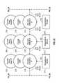
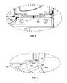
- FIG. 1including FIGS. 1A and 1B , are perspective views of a portable articulated arm coordinate measuring machine (AACMM) having embodiments of various aspects of the present invention therewithin;
- AACMMportable articulated arm coordinate measuring machine
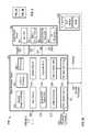
- FIG. 2is a block diagram of electronics utilized as part of the AACMM of FIG. 1 in accordance with an embodiment
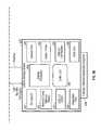
- FIG. 3is a block diagram describing detailed features of the electronic data processing system of FIG. 2 in accordance with an embodiment
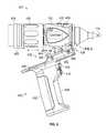
- FIG. 4is an isometric view of the probe end of the AACMM of FIG. 1 ;
- FIG. 5is a side view of the probe end of FIG. 4 with the handle being coupled thereto;
- FIG. 6is a side view of the probe end of FIG. 4 with the handle attached;
- FIG. 7is an enlarged partial side view of the interface portion of the probe end of FIG. 6 ;
- FIG. 8is another enlarged partial side view of the interface portion of the probe end of FIG. 5 ;
- FIG. 9is an isometric view partially in section of the handle of FIG. 4 ;
- FIG. 10is an isometric view of the probe end of the AACMM of FIG. 1 with a structured light device having a single camera attached;
- FIG. 11is an isometric view partially in section of the device of FIG. 10 ;
- FIG. 12is an isometric view of the probe end of the AACMM of FIG. 1 with another structured light device having dual cameras attached;
- FIG. 13A and FIG. 13Bare schematic views illustrating the operation of the device of FIG. 10 when attached to the probe end of the AACMM of FIG. 1 ;
- FIGS. 14A-14B , FIG. 15 , FIG. 16 and FIGS. 17A-17Care sequential projections having an uncoded binary pattern that may be emitted by the structured light device of FIG. 10 or FIG. 12 , in accordance with an embodiment of the present invention
- FIGS. 18-19are spatially varying color coded patterns that may be emitted by the structured light device of FIG. 10 or FIG. 12 , in accordance with an embodiment of the invention.
- FIGS. 20-23are strip index coded patterns that may be emitted by the structured light device of FIG. 10 or FIG. 12 , in accordance with an embodiment of the invention.
- FIGS. 24-31are two-dimensional grid patterns that may be emitted by the structured light device of FIG. 10 or FIG. 12 , in accordance with an embodiment of the invention.
- FIG. 32is a schematic illustration of a photometric technique for acquiring patterns of structured light under a plurality of lighting conditions
- FIG. 33is an illustration of a structured light scanner device independently operable from an AACMM in accordance with another embodiment of the invention.
- FIG. 34is a isometric drawing of a probe end having a triangulation scanner and camera used together to produce sharp 3D representations
- FIG. 35is a schematic illustration of rays projected through a camera perspective center to provide sharp edges for 3D representations.
- FIG. 36is an illustration showing a hole having edges having a surrounding region having a “fuzzy”.
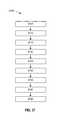
- FIG. 37illustrates a flow diagram of a method for determining 3D coordinates of an edge point located on an edge feature using a combination of a projector, a scanner camera, and an edge-detection camera, in accordance with an embodiment.
- AACMMPortable articulated arm coordinate measuring machines
- Embodiments of the present inventionprovide advantages in allowing an operator to easily and quickly couple accessory devices to a probe end of the AACMM that use structured light to provide for the non-contact measuring of a three-dimensional object.
- Embodiments of the present inventionprovide further advantages in providing for communicating data representing a point cloud measured by the structured light device within the AACMM.
- Embodiments of the present inventionprovide advantages in greater uniformity in the distribution of measured points that may provide enhanced accuracy.
- Embodiments of the present inventionprovide still further advantages in providing power and data communications to a removable accessory without having external connections or wiring.
- Embodiments of the present inventionprovide still further advantages in sharpening edges of features in 3D representations.
- structured lightrefers to a two-dimensional pattern of light projected onto a continuous and enclosed area of an object that conveys information which may be used to determine coordinates of points on the object.
- a structured light patternwill contain at least three non-collinear pattern elements disposed within the contiguous and enclosed area. Each of the three non-collinear pattern elements conveys information which may be used to determine the point coordinates.
- a coded light patternis one in which the three dimensional coordinates of an illuminated surface of the object may be ascertained by the acquisition of a single image.
- the projecting devicemay be moving relative to the object.
- a coded light patternthere will be no significant temporal relationship between the projected pattern and the acquired image.
- a coded light patternwill contain a set of elements (e.g. geometric shapes) arranged so that at least three of the elements are non-collinear.
- the set of elementsmay be arranged into collections of lines. Having at least three of the element be non-collinear ensures that the pattern is not a simple line pattern as would be projected, for example, by a laser line scanner. As a result, the pattern elements are recognizable because of the arrangement of the elements.
- an uncoded structured light pattern as used hereinis a pattern that does not allow measurement through a single pattern when the projector is moving relative to the object.
- An example of an uncoded light patternis one which requires a series of sequential patterns and thus the acquisition of a series of sequential images. Due to the temporal nature of the projection pattern and acquisition of the image, there should be no relative movement between the projector and the object.
- structured lightis different from light projected by a laser line probe or laser line scanner type device that generates a line of light.
- laser line probes used with articulated arms todayhave irregularities or other aspects that may be regarded as features within the generated lines, these features are disposed in a collinear arrangement. Consequently such features within a single generated line are not considered to make the projected light into structured light.
- FIGS. 1A and 1Billustrate, in perspective, an AACMM 100 according to various embodiments of the present invention, an articulated arm being one type of coordinate measuring machine.
- the exemplary AACMM 100may comprise a six or seven axis articulated measurement device having a probe end 401 that includes a measurement probe housing 102 coupled to an arm portion 104 of the AACMM 100 at one end.
- the arm portion 104comprises a first arm segment 106 coupled to a second arm segment 108 by a first grouping of bearing cartridges 110 (e.g., two bearing cartridges).
- a second grouping of bearing cartridges 112couples the second arm segment 108 to the measurement probe housing 102 .
- a third grouping of bearing cartridges 114couples the first arm segment 106 to a base 116 located at the other end of the arm portion 104 of the AACMM 100 .
- Each grouping of bearing cartridges 110 , 112 , 114provides for multiple axes of articulated movement.
- the probe end 401may include a measurement probe housing 102 that comprises the shaft of the seventh axis portion of the AACMM 100 (e.g., a cartridge containing an encoder system that determines movement of the measurement device, for example a probe 118 , in the seventh axis of the AACMM 100 ). In this embodiment, the probe end 401 may rotate about an axis extending through the center of measurement probe housing 102 .
- the base 116is typically affixed to a work surface.
- Each bearing cartridge within each bearing cartridge grouping 110 , 112 , 114typically contains an encoder system (e.g., an optical angular encoder system).
- the encoder systemi.e., transducer
- the arm segments 106 , 108may be made from a suitably rigid material such as but not limited to a carbon composite material for example.
- a portable AACMM 100 with six or seven axes of articulated movementprovides advantages in allowing the operator to position the probe 118 in a desired location within a 360° area about the base 116 while providing an arm portion 104 that may be easily handled by the operator.
- an arm portion 104 having two arm segments 106 , 108is for exemplary purposes, and the claimed invention should not be so limited.
- An AACMM 100may have any number of arm segments coupled together by bearing cartridges (and, thus, more or less than six or seven axes of articulated movement or degrees of freedom).
- the probe 118is detachably mounted to the measurement probe housing 102 , which is connected to bearing cartridge grouping 112 .
- a handle 126is removable with respect to the measurement probe housing 102 by way of, for example, a quick-connect interface. As will be discussed in more detail below, the handle 126 may be replaced with another device configured to emit a structured light to provide non-contact measurement of three-dimensional objects, thereby providing advantages in allowing the operator to make both contact and non-contact measurements with the same AACMM 100 .
- the probe housing 102houses a removable probe 118 , which is a contacting measurement device and may have different tips 118 that physically contact the object to be measured, including, but not limited to: ball, touch-sensitive, curved and extension type probes.
- the measurementis performed, for example, by a non-contacting device such as a coded structured light scanner device.
- a non-contacting devicesuch as a coded structured light scanner device.
- the handle 126is replaced with the coded structured light scanner device using the quick-connect interface.
- Other types of measurement devicesmay replace the removable handle 126 to provide additional functionality. Examples of such measurement devices include, but are not limited to, one or more illumination lights, a temperature sensor, a thermal scanner, a bar code scanner, a projector, a paint sprayer, a camera, or the like, for example.
- the AACMM 100includes the removable handle 126 that provides advantages in allowing accessories or functionality to be changed without removing the measurement probe housing 102 from the bearing cartridge grouping 112 .
- the removable handle 126may also include an electrical connector that allows electrical power and data to be exchanged with the handle 126 and the corresponding electronics located in the probe end 401 .
- each grouping of bearing cartridges 110 , 112 , 114allows the arm portion 104 of the AACMM 100 to move about multiple axes of rotation.
- each bearing cartridge grouping 110 , 112 , 114includes corresponding encoder systems, such as optical angular encoders for example, that are each arranged coaxially with the corresponding axis of rotation of, e.g., the arm segments 106 , 108 .
- the optical encoder systemdetects rotational (swivel) or transverse (hinge) movement of, e.g., each one of the arm segments 106 , 108 about the corresponding axis and transmits a signal to an electronic data processing system within the AACMM 100 as described in more detail herein below.
- Each individual raw encoder countis sent separately to the electronic data processing system as a signal where it is further processed into measurement data.
- No position calculator separate from the AACMM 100 itselfe.g., a serial box
- the base 116may include an attachment device or mounting device 120 .
- the mounting device 120allows the AACMM 100 to be removably mounted to a desired location, such as an inspection table, a machining center, a wall or the floor for example.
- the base 116includes a handle portion 122 that provides a convenient location for the operator to hold the base 116 as the AACMM 100 is being moved.
- the base 116further includes a movable cover portion 124 that folds down to reveal a user interface, such as a display screen.
- the base 116 of the portable AACMM 100contains or houses an electronic circuit having an electronic data processing system that includes two primary components: a base processing system that processes the data from the various encoder systems within the AACMM 100 as well as data representing other arm parameters to support three-dimensional (3-D) positional calculations; and a user interface processing system that includes an on-board operating system, a touch screen display, and resident application software that allows for relatively complete metrology functions to be implemented within the AACMM 100 without the need for connection to an external computer.
- a base processing systemthat processes the data from the various encoder systems within the AACMM 100 as well as data representing other arm parameters to support three-dimensional (3-D) positional calculations
- a user interface processing systemthat includes an on-board operating system, a touch screen display, and resident application software that allows for relatively complete metrology functions to be implemented within the AACMM 100 without the need for connection to an external computer.
- the electronic data processing system in the base 116may communicate with the encoder systems, sensors, and other peripheral hardware located away from the base 116 (e.g., a structured light device that can be mounted to the removable handle 126 on the AACMM 100 ).
- the electronics that support these peripheral hardware devices or featuresmay be located in each of the bearing cartridge groupings 110 , 112 , 114 located within the portable AACMM 100 .
- FIG. 2is a block diagram of electronics utilized in an AACMM 100 in accordance with an embodiment.
- the embodiment shown in FIG. 2Aincludes an electronic data processing system 210 including a base processor board 204 for implementing the base processing system, a user interface board 202 , a base power board 206 for providing power, a Bluetooth module 232 , and a base tilt board 208 .
- the user interface board 202includes a computer processor for executing application software to perform user interface, display, and other functions described herein.
- each encoder systemgenerates encoder data and includes: an encoder arm bus interface 214 , an encoder digital signal processor (DSP) 216 , an encoder read head interface 234 , and a temperature sensor 212 .
- DSPdigital signal processor
- Other devices, such as strain sensors,may be attached to the arm bus 218 .
- the probe end electronics 230include a probe end DSP 228 , a temperature sensor 212 , a handle/device interface bus 240 that connects with the handle 126 or the coded structured light scanner device 242 via the quick-connect interface in an embodiment, and a probe interface 226 .
- the quick-connect interfaceallows access by the handle 126 to the data bus, control lines, and power bus used by the coded structured light scanner device 242 and other accessories.
- the probe end electronics 230are located in the measurement probe housing 102 on the AACMM 100 .
- the handle 126may be removed from the quick-connect interface and measurement may be performed by the structured light device 242 communicating with the probe end electronics 230 of the AACMM 100 via the interface bus 240 .
- the electronic data processing system 210is located in the base 116 of the AACMM 100
- the probe end electronics 230are located in the measurement probe housing 102 of the AACMM 100
- the encoder systemsare located in the bearing cartridge groupings 110 , 112 , 114 .
- the probe interface 226may connect with the probe end DSP 228 by any suitable communications protocol, including commercially-available products from Maxim Integrated Products, Inc. that embody the 1-Wire® communications protocol 236 .
- FIG. 3is a block diagram describing detailed features of the electronic data processing system 210 of the AACMM 100 in accordance with an embodiment.
- the electronic data processing system 210is located in the base 116 of the AACMM 100 and includes the base processor board 204 , the user interface board 202 , a base power board 206 , a Bluetooth module 232 , and a base tilt module 208 .
- the base processor board 204includes the various functional blocks illustrated therein.
- a base processor function 302is utilized to support the collection of measurement data from the AACMM 100 and receives raw arm data (e.g., encoder system data) via the arm bus 218 and a bus control module function 308 .
- the memory function 304stores programs and static arm configuration data.
- the base processor board 204also includes an external hardware option port function 310 for communicating with any external hardware devices or accessories such as a coded structured light scanner device 242 .
- a real time clock (RTC) and log 306 , a battery pack interface (IF) 316 , and a diagnostic port 318are also included in the functionality in an embodiment of the base processor board 204 depicted in FIG. 3A .
- the base processor board 204also manages all the wired and wireless data communication with external (host computer) and internal (display processor 202 ) devices.
- the base processor board 204has the capability of communicating with an Ethernet network via an Ethernet function 320 (e.g., using a clock synchronization standard such as Institute of Electrical and Electronics Engineers (IEEE) 1588), with a wireless local area network (WLAN) via a LAN function 322 , and with Bluetooth module 232 via a parallel to serial communications (PSC) function 314 .
- the base processor board 204also includes a connection to a universal serial bus (USB) device 312 .
- USBuniversal serial bus
- the base processor board 204transmits and collects raw measurement data (e.g., encoder system counts, temperature readings) for processing into measurement data without the need for any preprocessing, such as disclosed in the serial box of the aforementioned '582 patent.
- the base processor 204sends the processed data to the display processor 328 on the user interface board 202 via an RS485 interface (IF) 326 .
- the base processor 204also sends the raw measurement data to an external computer.
- the angle and positional data received by the base processoris utilized by applications executing on the display processor 328 to provide an autonomous metrology system within the AACMM 100 .
- Applicationsmay be executed on the display processor 328 to support functions such as, but not limited to: measurement of features, guidance and training graphics, remote diagnostics, temperature corrections, control of various operational features, connection to various networks, and display of measured objects.
- the user interface board 202includes several interface options including a secure digital (SD) card interface 330 , a memory 332 , a USB Host interface 334 , a diagnostic port 336 , a camera port 340 , an audio/video interface 342 , a dial-up/cell modem 344 and a global positioning system (GPS) port 346 .
- SDsecure digital
- the electronic data processing system 210 shown in FIG. 3Aalso includes a base power board 206 with an environmental recorder 362 for recording environmental data.
- the base power board 206also provides power to the electronic data processing system 210 using an AC/DC converter 358 and a battery charger control 360 .
- the base power board 206communicates with the base processor board 204 using inter-integrated circuit (I2C) serial single ended bus 354 as well as via a DMA serial peripheral interface (DSPI) 357 .
- I2Cinter-integrated circuit
- DSPIDMA serial peripheral interface
- the base power board 206is connected to a tilt sensor and radio frequency identification (RFID) module 208 via an input/output (I/O) expansion function 364 implemented in the base power board 206 .
- RFIDradio frequency identification
- the base processor board 204 and the user interface board 202are combined into one physical board.
- the device 400includes an enclosure 402 that includes a handle portion 404 that is sized and shaped to be held in an operator's hand, such as in a pistol grip for example.
- the enclosure 402is a thin wall structure having a cavity 406 ( FIG. 9 ).
- the cavity 406is sized and configured to receive a controller 408 .
- the controller 408may be a digital circuit, having a microprocessor for example, or an analog circuit.
- the controller 408is in asynchronous bidirectional communication with the electronic data processing system 210 ( FIGS. 2 and 3 ).
- the communication connection between the controller 408 and the electronic data processing system 210may be wired (e.g. via controller 420 ) or may be a direct or indirect wireless connection (e.g. Bluetooth or IEEE 802.11) or a combination of wired and wireless connections.
- the enclosure 402is formed in two halves 410 , 412 , such as from an injection molded plastic material for example.
- the halves 410 , 412may be secured together by fasteners, such as screws 414 for example.
- the enclosure halves 410 , 412may be secured together by adhesives or ultrasonic welding for example.
- the handle portion 404also includes buttons or actuators 416 , 418 that may be manually activated by the operator.
- the actuators 416 , 418are coupled to the controller 408 that transmits a signal to a controller 420 within the probe housing 102 .
- the actuators 416 , 418perform the functions of actuators 422 , 424 located on the probe housing 102 opposite the device 400 .
- the device 400may have additional switches, buttons or other actuators that may also be used to control the device 400 , the AACMM 100 or vice versa.
- the device 400may include indicators, such as light emitting diodes (LEDs), sound generators, meters, displays or gauges for example.
- the device 400may include a digital voice recorder that allows for synchronization of verbal comments with a measured point.
- the device 400includes a microphone that allows the operator to transmit voice activated commands to the electronic data processing system 210 .
- the handle portion 404may be configured to be used with either operator hand or for a particular hand (e.g. left handed or right handed).
- the handle portion 404may also be configured to facilitate operators with disabilities (e.g. operators with missing finders or operators with prosthetic arms).
- the handle portion 404may be removed and the probe housing 102 used by itself when clearance space is limited.
- the probe end 401may also comprise the shaft of the seventh axis of AACMM 100 .
- the device 400may be arranged to rotate about the AACMM seventh axis.
- the probe end 401includes a mechanical and electrical interface 426 having a first connector 429 ( FIG. 8 ) on the device 400 that cooperates with a second connector 428 on the probe housing 102 .
- the connectors 428 , 429may include electrical and mechanical features that allow for coupling of the device 400 to the probe housing 102 .
- the interface 426includes a first surface 430 having a mechanical coupler 432 and an electrical connector 434 thereon.
- the enclosure 402also includes a second surface 436 positioned adjacent to and offset from the first surface 430 .
- the second surface 436is a planar surface offset a distance of approximately 0.5 inches from the first surface 430 .
- the interface 426provides for a relatively quick and secure electronic connection between the device 400 and the probe housing 102 without the need to align connector pins, and without the need for separate cables or connectors.
- the electrical connector 434extends from the first surface 430 and includes one or more connector pins 440 that are electrically coupled in asynchronous bidirectional communication with the electronic data processing system 210 ( FIGS. 2 and 3 ), such as via one or more arm buses 218 for example.
- the bidirectional communication connectionmay be wired (e.g. via arm bus 218 ), wireless (e.g. Bluetooth or IEEE 802.11), or a combination of wired and wireless connections.
- the electrical connector 434is electrically coupled to the controller 420 .
- the controller 420may be in asynchronous bidirectional communication with the electronic data processing system 210 such as via one or more arm buses 218 for example.
- the electrical connector 434is positioned to provide a relatively quick and secure electronic connection with electrical connector 442 on probe housing 102 .
- the electrical connectors 434 , 442connect with each other when the device 400 is attached to the probe housing 102 .
- the electrical connectors 434 , 442may each comprise a metal encased connector housing that provides shielding from electromagnetic interference as well as protecting the connector pins and assisting with pin alignment during the process of attaching the device 400 to the probe housing 102 .
- the mechanical coupler 432provides relatively rigid mechanical coupling between the device 400 and the probe housing 102 to support relatively precise applications in which the location of the device 400 on the end of the arm portion 104 of the AACMM 100 preferably does not shift or move. Any such movement may typically cause an undesirable degradation in the accuracy of the measurement result.
- the mechanical coupler 432includes a first projection 444 positioned on one end 448 (the leading edge or “front” of the device 400 ).
- the first projection 444may include a keyed, notched or ramped interface that forms a lip 446 that extends from the first projection 444 .
- the lip 446is sized to be received in a slot 450 defined by a projection 452 extending from the probe housing 102 ( FIG. 8 ).
- the first projection 444 and the slot 450 along with the collar 438form a coupler arrangement such that when the lip 446 is positioned within the slot 450 , the slot 450 may be used to restrict both the longitudinal and lateral movement of the device 400 when attached to the probe housing 102 .
- the rotation of the collar 438may be used to secure the lip 446 within the slot 450 .
- the mechanical coupler 432may include a second projection 454 .
- the second projection 454may have a keyed, notched-lip or ramped interface surface 456 ( FIG. 5 ).
- the second projection 454is positioned to engage a fastener associated with the probe housing 102 , such as collar 438 for example.
- the mechanical coupler 432includes a raised surface projecting from surface 430 that adjacent to or disposed about the electrical connector 434 which provides a pivot point for the interface 426 ( FIGS. 7 and 8 ). This serves as the third of three points of mechanical contact between the device 400 and the probe housing 102 when the device 400 is attached thereto.
- the probe housing 102includes a collar 438 arranged co-axially on one end.
- the collar 438includes a threaded portion that is movable between a first position ( FIG. 5 ) and a second position ( FIG. 7 ).
- the collar 438may be used to secure or remove the device 400 without the need for external tools.
- Rotation of the collar 438moves the collar 438 along a relatively coarse, square-threaded cylinder 474 .
- the use of such relatively large size, square-thread and contoured surfacesallows for significant clamping force with minimal rotational torque.
- the coarse pitch of the threads of the cylinder 474further allows the collar 438 to be tightened or loosened with minimal rotation.
- the lip 446is inserted into the slot 450 and the device is pivoted to rotate the second projection 454 toward surface 458 as indicated by arrow 464 ( FIG. 5 ).
- the collar 438is rotated causing the collar 438 to move or translate in the direction indicated by arrow 462 into engagement with surface 456 .
- the movement of the collar 438 against the angled surface 456drives the mechanical coupler 432 against the raised surface 460 . This assists in overcoming potential issues with distortion of the interface or foreign objects on the surface of the interface that could interfere with the rigid seating of the device 400 to the probe housing 102 .
- FIG. 5includes arrows 462 , 464 to show the direction of movement of the device 400 and the collar 438 .
- the offset distance of the surface 436 of device 400provides a gap 472 between the collar 438 and the surface 436 ( FIG. 6 ).
- the gap 472allows the operator to obtain a firmer grip on the collar 438 while reducing the risk of pinching fingers as the collar 438 is rotated.
- the probe housing 102is of sufficient stiffness to reduce or prevent the distortion when the collar 438 is tightened.
- Embodiments of the interface 426allow for the proper alignment of the mechanical coupler 432 and electrical connector 434 and also protects the electronics interface from applied stresses that may otherwise arise due to the clamping action of the collar 438 , the lip 446 and the surface 456 . This provides advantages in reducing or eliminating stress damage to circuit board 476 mounted electrical connectors 434 , 442 that may have soldered terminals. Also, embodiments provide advantages over known approaches in that no tools are required for a user to connect or disconnect the device 400 from the probe housing 102 . This allows the operator to manually connect and disconnect the device 400 from the probe housing 102 with relative ease.
- a relatively large number of functionsmay be shared between the AACMM 100 and the device 400 .
- switches, buttons or other actuators located on the AACMM 100may be used to control the device 400 or vice versa.
- commands and datamay be transmitted from electronic data processing system 210 to the device 400 .
- the device 400is a video camera that transmits data of a recorded image to be stored in memory on the base processor 204 or displayed on the display 328 .
- the device 400is an image projector that receives data from the electronic data processing system 210 .
- temperature sensors located in either the AACMM 100 or the device 400may be shared by the other.
- embodiments of the present inventionprovide advantages in providing a flexible interface that allows a wide variety of accessory devices 400 to be quickly, easily and reliably coupled to the AACMM 100 . Further, the capability of sharing functions between the AACMM 100 and the device 400 may allow a reduction in size, power consumption and complexity of the AACMM 100 by eliminating duplicity.
- the controller 408may alter the operation or functionality of the probe end 401 of the AACMM 100 .
- the controller 408may alter indicator lights on the probe housing 102 to either emit a different color light, a different intensity of light, or turn on/off at different times when the device 400 is attached versus when the probe housing 102 is used by itself.
- the device 400includes a range finding sensor (not shown) that measures the distance to an object.
- the controller 408may change indicator lights on the probe housing 102 in order to provide an indication to the operator how far away the object is from the probe tip 118 .
- the controller 408may change the color of the indicator lights based on the quality of the image acquired by the coded structured light scanner device. This provides advantages in simplifying the requirements of controller 420 and allows for upgraded or increased functionality through the addition of accessory devices.
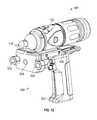
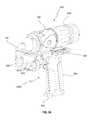
- inventions of the present inventionprovide advantages to projector, camera, signal processing, control and indicator interfaces for a non-contact three-dimensional measurement device 500 .
- the device 500includes a pair of optical devices, such as a light projector 508 and a camera 510 , for example, that project a structured light pattern and receive a two-dimensional pattern that was reflected from an object 501 .
- the device 500uses triangulation-based methods based on the known emitted pattern and the acquired image to determine a point cloud representing the X, Y, Z coordinate data for the object 501 for each pixel of the received image.
- the structured light patternis coded so that a single image is sufficient to determine the three-dimensional coordinates of object points. Such a coded structured light pattern may also be said to measure three-dimensional coordinates in a single shot.
- the projector 508uses a visible light source that illuminates a pattern generator.
- the visible light sourcemay be a laser, a superluminescent diode, an incandescent light, a light emitting diode (LED), or other light emitting device.
- the pattern generatoris a chrome-on-glass slide having a structured light pattern etched thereon. The slide may have a single pattern or multiple patterns that move in and out of position as needed. The slide may be manually or automatically installed in the operating position.
- the source patternmay be light reflected off or transmitted by a digital micro-mirror device (DMD) such as a digital light projector (DLP) manufactured by Texas Instruments Corporation, a liquid crystal device (LCD), a liquid crystal on silicon (LCOS) device, or a similar device used in transmission mode rather than reflection mode.
- DMDdigital micro-mirror device
- the projector 508may further include a lens system 515 that alters the outgoing light to have the desired focal characteristics.
- the device 500further includes an enclosure 502 with a handle portion 504 .
- the device 500may further include an interface 426 on one end that mechanically and electrically couples the device 500 to the probe housing 102 as described herein above.
- the device 500may be integrated into the probe housing 102 .
- the interface 426provides advantages in allowing the device 500 to be coupled and removed from the AACMM 100 quickly and easily without requiring additional tools.
- the camera 510includes a photosensitive sensor which generates a digital image/representation of the area within the sensor's field of view.
- the sensormay be charged-coupled device (CCD) type sensor or a complementary metal-oxide-semiconductor (CMOS) type sensor for example having an array of pixels.
- CMOScomplementary metal-oxide-semiconductor
- the camera 510may further include other components, such as but not limited to lens 503 and other optical devices for example.
- the projector 508 and the camera 510are arranged at an angle such that the sensor may receive light reflected from the surface of the object 501 .
- the projector 508 and camera 510are positioned such that the device 500 may be operated with the probe tip 118 in place.
- the device 500is substantially fixed relative to the probe tip 118 and forces on the handle portion 504 may not influence the alignment of the device 500 relative to the probe tip 118 .
- the device 500may have an additional actuator (not shown) that allows the operator to switch between acquiring data from the device 500 and the probe tip 118 .
- the projector 508 and camera 510are electrically coupled to a controller 512 disposed within the enclosure 502 .
- the controller 512may include one or more microprocessors, digital signal processors, memory and signal conditioning circuits. Due to the digital signal processing and large data volume generated by the device 500 , the controller 512 may be arranged within the handle portion 504 .
- the controller 512is electrically coupled to the arm buses 218 via electrical connector 434 .
- the device 500may further include actuators 514 , 516 which may be manually activated by the operator to initiate operation and data capture by the device 500 .
- the image processing to determine the X, Y, Z coordinate data of the point cloud representing object 501is performed by the controller 512 and the coordinate data is transmitted to the electronic data processing system 210 via bus 240 .
- imagesare transmitted to the electronic data processing system 210 and the calculation of the coordinates is performed by the electronic data processing system 210 .
- the controller 512is configured to communicate with the electronic data processing system 210 to receive structured light pattern images from the electronic data processing system 210 .
- the pattern emitted onto the objectmay be changed by the electronic data processing system 210 either automatically or in response to an input from the operator. This may provide advantages in obtaining higher accuracy measurements with less processing time by allowing the use of patterns that are simpler to decode when the conditions warrant, and use the more complex patterns where it is desired to achieve the desired level of accuracy or resolution.
- the device 520( FIG. 12 ) includes a pair of cameras 510 .
- the cameras 510are arranged on an angle relative to the projector 508 to receive reflected light from the object 501 .
- the use of multiple cameras 510may provide advantages in some applications by providing redundant images to increase the accuracy of the measurement.
- the redundant imagesmay allow for sequential patterns to be quickly acquired by the device 500 by increasing the acquisition speed of images by alternately operating the cameras 510 .
- the device 500first emits a structured light pattern 522 with projector 508 onto surface 524 of the object 501 .
- the structured light pattern 522may include the patterns disclosed in the journal article “DLP-Based Structured Light 3D Imaging Technologies and Applications” by Jason Geng published in the Proceedings of SPIE, Vol. 7932, which is incorporated herein by reference.
- the structured light pattern 522may further include, but is not limited to one of the patterns shown in FIGS. 14-32 .
- the light 509 from projector 508is reflected from the surface 524 and the reflected light 511 is received by the camera 510 .
- variations in the surface 524create distortions in the structured pattern when the image of the pattern is captured by the camera 510 .
- the patternis formed by structured light, it is possible in some instances for the controller 512 or the electronic data processing system 210 to determine a one to one correspondence between the pixels in the emitted pattern, such as pixel 513 for example, and the pixels in the imaged pattern, such as pixel 515 for example. This enables triangulation principals to be used to determine the coordinates of each pixel in the imaged pattern.
- the collection of three-dimensional coordinates of the surface 524is sometimes referred to as a point cloud.
- a point cloudmay be created of the entire object 501 .
- the coupling of the device 500 to the probe endprovides advantages in that the position and orientation of the device 500 is known by the electronic data processing system 210 , so that the location of the object 501 relative to the AACMM 100 may also be ascertained.
- the angle of each projected ray of light 509 intersecting the object 522 in a point 527is known to correspond to a projection angle phi ( ⁇ ), so that ⁇ information is encoded into the emitted pattern.
- the systemis configured to enable the ⁇ value corresponding to each pixel in the imaged pattern to be ascertained.
- an angle omega ( ⁇ ) for each pixel in the camerais known, as is the baseline distance “D” between the projector 508 and the camera. Therefore, the distance “Z” from the camera 510 to the location that the pixel has imaged using the equation:
- a common form of uncoded structured lightsuch as that shown in FIGS. 14-17 and 28-30 , relies on a striped pattern varying in a periodic manner along one dimension. These types of patterns are usually applied in a sequence to provide an approximate distance to the object. Some uncoded pattern embodiments, such as the sinusoidal patterns for example, may provide relatively highly accurate measurements. However, for these types of patterns to be effective, it is usually necessary for the scanner device and the object to be held stationary relative to each other. Where the scanner device or the object are in motion (relative to the other), then a coded pattern, such as that shown in FIGS. 18-27 may be preferable.
- a coded patternallows the image to be analyzed using a single acquired image.
- Some coded patternsmay be placed in a particular orientation on the projector pattern (for example, perpendicular to epipolar lines on the projector plane), thereby simplifying analysis of the three-dimensional surface coordinates based on a single image.
- Epipolar linesare mathematical lines formed by the intersection of epipolar planes and the source plane 517 or the image plane 521 (the plane of the camera sensor) in FIG. 13B .
- An epipolar planemay be any plane that passes through the projector perspective center 519 and the camera perspective center.
- the epipolar lines on the source plane 517 and the image plane 521may be parallel in some cases, but in general are not parallel.
- An aspect of epipolar linesis that a given epipolar line on the projector plane 517 has a corresponding epipolar line on the image plane 521 . Therefore, any particular pattern known on an epipolar line in the projector plane 517 may be immediately observed and evaluated in the image plane 521 .
- the spacing between the coded elements in the image plane 521may be determined using the values read out of the pixels of the camera sensor 510 . This information may be used to determine the three-dimensional coordinates of a point 527 on the object 501 . It is further possible to tilt coded patterns at a known angle with respect to an epipolar line and efficiently extract object surface coordinates. Examples of coded patterns are shown in FIGS. 20-29 .
- the sinusoidal periodrepresents a plurality of pattern elements. Since there is a multiplicity of periodic patterns in two-dimensions, the pattern elements are non-collinear. In some cases, a striped pattern having stripes of varying width may represent a coded pattern.
- gray codeas used in the field of three-dimensional metrology based on structured light is somewhat different than the term as used in the field of electrical engineering, where the term Gray code commonly means the sequential changing of a single bit at a time.
- Gray codecommonly means the sequential changing of a single bit at a time.
- the present applicationfollows the use of the term gray code as is customary for the field of three-dimensional metrology where the gray code typically represents a sequence of binary black and white values.
- FIG. 14Ashows an example of a binary pattern that includes a plurality of sequential images 530 , 532 , 534 , each having a different stripped pattern thereon.
- the stripesalternate between bright (illuminated) and dark (non-illuminated) striped regions.
- the terms white and blackare used to mean illuminated and non-illuminated, respectively.
- the composite pattern 536For each point on the object 501 (represented by a camera pixel in the image) the composite pattern 536 has a unique binary value obtained through the sequential projection of patterns 530 , 532 , 534 , 535 , 537 , which correspond to a relatively small range of possible projection angles ⁇ .
- Eq. (1)may be used to find the distance Z from the camera to the object point.
- a two-dimensional angleis known for each camera pixel. The two-dimensional angle corresponds generally to the one-dimensional angle Omega, which is used in the calculation of the distance Z according to Eq. (1).
- a line drawn from each camera pixel through the camera perspective center and intersecting the object in a pointdefines a two-dimensional angle in space.
- the two pixel anglesprovide three-dimensional coordinates corresponding to a point on the object surface.
- the term grey-scaleusually refers to an amount of irradiance at a point on the object from white (maximum light), to various levels of gray (less light), to black (minimum light). This same nomenclature is used even if the light being projected has a color such as red, and the gray-scale values correspond to levels of red illumination.
- the patternFIG. 15
- the grey scale valuesmay be used to determine the possible projection angles ⁇ to within a relatively small range of possible values. As discussed hereinabove, Eq. (1) may then be used to determine the distance Z.
- the distance Z to an object pointmay be found by measuring a phase shift observed in a plurality of images.
- the gray-scale intensities 546 , 548 , 550 of a projector pattern 552vary in a sinusoidal manner, but with the phase shifted between projected patterns.
- the sinusoid gray-scale intensity 546(representing optical power per unit area) may have a phase of zero degrees at a particular point.
- the sinusoid intensity 548has a phase of 120 degrees at the same point.
- the sinusoid intensity 550may have a phase of 240 degrees at the same point.
- phase shift methodis used to determine a phase of the projected light at each camera pixel, which eliminates the need to consider information from adjacent pixels as in the coded-pattern single shot case.
- Many methodsmay be used to determine the phase of a camera pixel.
- One methodinvolves performing a multiply and accumulate procedure and then taking an arctangent of a quotient. This method is well known to those of ordinary skill in the art and is not discussed further.
- the background lightcancels out in the calculation of phase.
- the value Z calculated for a give pixelis usually more accurate than the value Z calculated using a coded-pattern single shot method.
- all of the calculated phasesvary from 0 to 360 degrees.
- these calculated phasesmay be adequate if “thickness” of the object under test does not vary by too much because the angle for each projected stripe is known ahead of time.
- an ambiguitymay arise between in the phase calculated for a particular pixel since that pixel may have been obtained from first projected ray of light striking the object at a first position or a second projected ray of light striking the object at a second position.
- the phasesmay not be properly decoded and the desired one to one correspondence not achieved.
- FIG. 17Ashows a sequence 1 - 4 of projected gray-code intensities 554 according to a method by which the ambiguity may be eliminated in the distance Z based on a calculated phase.
- a collection of gray code patternsare projected sequentially onto the object.
- the sequential pattern 1has dark (black) on the left half of the pattern (elements 0 - 15 ) and bright (white) on the right half of the pattern (elements 16 - 31 ).
- the sequential pattern 2has a dark band toward the center (elements 8 - 23 ) and bright bands toward the edges (elements 2 - 7 , 24 - 31 ).
- the sequential pattern 3has two separated bright bands near the center (elements 4 - 11 , 20 - 27 ) and three bright bands (elements 0 - 3 , 12 - 19 , 28 - 31 ).
- the sequential pattern 4has four separated dark bands (elements 2 - 5 , 10 - 13 , 18 - 21 , 26 - 29 ) and five separated bright bands (elements 0 - 1 , 6 - 9 , 14 - 17 , 22 - 25 , 30 - 31 ). For any given pixel in the camera, this sequence of patterns enables the “object thickness region” of the object to be improved by a factor of 16 compared to an initial object thickness region corresponding to all the elements 0 to 31 .
- a phase shift methodsimilar to the method of FIG. 16 , is performed.
- a pattern 556 Afour sinusoidal periods are projected onto an object.
- One way to reduce or eliminate the ambiguityis to project one or more additional sinusoidal patterns 556 B, 556 C, each pattern having a different fringe period (pitch). So, for example, in FIG. 17B , a second sinusoidal pattern 555 having three fringe periods rather than four fringe periods is projected onto an object.
- the difference in the phases for the two patterns 555 , 556may be used to help eliminate an ambiguity in the distance Z to the target.
- Another method for eliminating ambiguityis to use a different type of method, such as the gray code method of FIG. 17A for example, to eliminate the ambiguity in the distances Z calculated using the sinusoidal phase shift method.
- patterns 558 , 566have a distribution of colors that may in some cases enable measurement of the object to be based on a single (coded) image.
- the pattern 558uses lines having a continuously spatially varying wavelength of light to create a pattern where the color changes continuously from blue to green to yellow to red to fuchsia for example. Thus for each particular spectral wavelength, a one-to-one correspondence may be made between the emitted image and the imaged pattern.
- the three-dimensional coordinates of the object 501may be determined from a single imaged pattern.
- the stripes of the pattern 558are oriented perpendicular to the epipolar lines on the projector plane. Since the epipolar lines on the projector plane map into epipolar lines on the camera image plane, it is possible to obtain an association between projector points and camera points by moving along the direction of epipolar lines in the camera image plane and noting the color of the line in each case. It should be appreciated that each pixel in the camera image plane corresponds to a two-dimensional angle. The color enables determination of the one-to-one correspondence between particular projection angles and particular camera angles.
- This correspondence informationcombined with the distance between the camera and the projector (the baseline distance D) and the angles of the camera and projector relative to the baseline, is sufficient to enable determination of the distance Z from the camera to the object.
- FIG. 19Another embodiment using color patterns is shown in FIG. 19 .
- a plurality of colored patterns having varying intensities 560 , 562 , 564are combined to create a color pattern 566 .
- the plurality of colored patterns intensities 560 , 562 , 564are primary colors, such that pattern 560 varies the intensity of the color red, pattern 562 varies the intensity of the color green and pattern 564 varies the intensity of the color blue. Since the ratios of colors are known, the resulting emitted image has a known relationship that may be decoded in the imaged pattern.
- the three-dimensional coordinates of the object 501may be determined. Unlike the pattern of FIG.
- the pattern of FIG. 19projects three complete cycles of nearly identical colors.
- the pattern of FIG. 18there is little possibility of ambiguity in the measured distance Z (at least for the case in which the projected lines are perpendicular to epipolar lines) since each camera pixel recognizes a particular color that corresponds uniquely to a particular projection direction. Since the camera angle and projection angles are known, triangulation may be used to determine the three-dimensional object coordinates at each pixel position using only a single camera image.
- the method of FIG. 18may be considered to be a coded, single-shot method.
- FIG. 19there is a chance of ambiguity in the distance Z to an object point.
- the projectormay have projected any of three different angles. Based on the triangulation geometry, three different distances Z are possible. If the thickness of the object is known ahead of time to be within a relatively small range of values, then it may be possible to eliminate two of the values, thereby obtaining three-dimensional coordinates in a single shot. In the general case, however, it would be necessary to use additional projected patterns to eliminate the ambiguity. For example, the spatial period of the colored pattern may be changed, and then used to illuminate the object a second time. In this instance, this method of projected structured light is considered to be a sequential method rather than a coded, single-shot method.
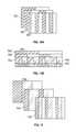
- coded structured light patterns for a single image acquisitionare shown based on a stripe indexing technique.
- patterns having color stripes 568 , 570are emitted by the projector 508 .
- This techniqueutilizes a characteristic of image sensors wherein the sensor has three independent color channels, such as red, green, blue or cyan, yellow, magenta for example. The combinations of the values generated by these sensor channels may produce a large number of colored patterns.
- the ratio of the color distributionis known, therefore the relationship between the emitted pattern and the imaged pattern may be determined and the three-dimensional coordinates calculated.
- Still other types of colored patternsmay be used, such as a pattern based on the De Bruijn sequence.
- the stripe indexing techniques and the De Bruijn sequenceare well known to those of ordinary skill in the art and so are not discussed further.
- the pattern 572provides groups of stripes having multiple intensity (gray-scale) levels and different widths. As a result, a particular group of stripes within the overall image has a unique gray-scale pattern. Due to the uniqueness of the groups, a one-to-one correspondence may be determined between the emitted pattern and the imaged pattern to calculate the coordinates of the object 501 .
- the pattern 574provides a series of stripes having a segmented pattern. Since each line has unique segment design, the correspondence may be determined between the emitted pattern and the imaged pattern to calculate the coordinates of the object 501 .
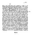
- coded structured light patternsare shown that use a two-dimensional spatial grid pattern technique. These types of patterns are arranged such that a sub window, such as window 576 on pattern 578 for example, is unique relative to other sub windows within the pattern.
- a pseudo random binary array pattern 578is used.
- the pattern 578uses a grid with elements, such as circles 579 for example, that form the coded pattern. It should be appreciated that elements having other geometric shapes may also be used, such as but not limited to squares, rectangles, and triangles for example.
- a pattern 580is shown of a multi-valued pseudo random array wherein each of the numerical values has an assigned shape 582 .
- These shapes 582form a unique sub-window 584 that allows for correspondence between the emitted pattern and the imaged pattern to calculate the coordinates of the object 501 .
- the grid 586is color coded with stripes perpendicular to the projector plane.
- the pattern of FIG. 26will not necessarily provide a pattern that can be decoded in a single shot, but the color information may help to simplify the analysis.
- an array 588 of colored shapessuch as squares or circles, for example, are used to form the pattern.
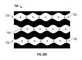
- an exemplary sinusoidal pattern 720is shown.
- the lines 734are perpendicular to epipolar lines on the projector plane.
- the sinusoidal pattern 720is made up of thirty lines 722 which are repeated once to give a total number of lines 722 of sixty.
- Each line 722has a sinusoidal feature 723 that is approximately 180 degrees out of phase with the line above and the line below. This is to allow the lines 722 to be as close as possible and also allows a greater depth of field because the lines can blur on the projected surface or acquired image and still be recognized.
- Each single line 722can be uniquely decoded using just the phase of that line where the line length must be at least one wavelength of the sinusoid.
- the pattern 720Since the pattern 720 is repeated, it would generally cause ambiguities in the line identification. However this is problem is resolved in this system through the geometry of the camera's field of view and depth of field. For a single view of the camera, i.e. a row of pixels, within the depth of field in which the lines can be optically resolved, no two lines with the same phase can be imaged. For example, the first row of pixels on the camera can only receive reflected light from lines 1 - 30 of the pattern. Whereas further down the camera sensor, another row will only receive reflected light from lines 2 - 31 of the pattern, and so on. In FIG. 28B an enlarged portion of the pattern 720 is shown of three lines where the phase between consecutive lines 722 is approximately 180 degrees. It also shows how the phase of each single line is enough to uniquely decode the lines.
- FIGS. 29A-29Banother pattern 730 is shown having square pattern elements.
- the lines 732are perpendicular to epipolar lines on the projector plane.
- the square pattern 730contains twenty seven lines 732 before the pattern 730 is repeated and has a total number of lines of 59.
- the code elements 734 of pattern 730are distinguished by the phase of the square wave from left to right in FIG. 29B .
- the pattern 730is encoded such that a group of sequential lines 732 are distinguished by the relative phases of its members. Within the image, sequential lines are found by scanning vertically for the lines. In an embodiment, scanning vertically means scanning along epipolar lines in the camera image plane. Sequential lines within a camera vertical pixel column are paired together and their relative phases are determined.
- FIG. 29Bshows an enlarged view of four lines 732 of the square pattern. This embodiment shows that the phase of a single line 732 alone is not able to uniquely decode a line because the first and third lines have the same absolute phase.
- This approach to code the relative phases versus the absolute phasesprovides advantages in that there is a higher tolerance for the positions of the phases. Minor errors in the construction of the projector which may cause the phases of the lines to shift throughout the depth of field of the camera, as well as errors due to the projector and camera lenses make an absolute phase much more difficult to determine. This can be overcome in the absolute phase method by increasing the period such that it is sufficiently large enough to overcome the error in determining the phase.
- each sinusoidal periodrepresents a plurality of pattern elements. Since there is a multiplicity of periodic patterns in two dimensions, the pattern elements are non-collinear. In contrast, for the case of the laser line scanner that emits a line of light, all of the pattern elements lie on a straight line.
- the linehas width and the tail of the line cross section may have less optical power than the peak of the signal, these aspects of the line are not evaluated separately in finding surface coordinates of an object and therefore do not represent separate pattern elements.
- the linemay contain multiple pattern elements, these pattern elements are collinear.
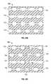
- FIGS. 30-31the various pattern techniques may be combined as shown in FIGS. 30-31 to form either a binary ( FIG. 30 ) checkerboard uncoded pattern 590 or a colored ( FIG. 31 ) checkerboard uncoded pattern 592 .
- a photometric stereo techniquemay be used where a plurality of images 594 are taken on the object 501 where the light source 596 is moved to a plurality of locations.
- the device 704is independently operable when detached from the AACMM 100 .
- the device 704includes a controller 706 and an optional display 708 .
- the display 708may be integrated in the housing of the device 704 or may be a separate component that is coupled to the device 704 when it is used independently from the AACMM 100 .
- the display 708may include a controller (not shown) that provides additional functionality to facilitate to independent operation of the device 704 .
- the controller 706is disposed within the separable display.
- the controller 706includes a communications circuit configured to wirelessly transmit data, such as images or coordinate data via a communications link 712 to the AACMM 100 , to a separate computing device 710 or a combination of both.
- the computing device 710may be, but is not limited to a computer, a laptop, a tablet computer, a personal digital assistant (PDA), or a cell phone for example.
- the display 708may allow the operator see the acquired images, or the point cloud of acquired coordinates of the object 702 .
- the controller 706decodes the patterns in the acquired image to determine the three-dimensional coordinates of the object.
- the imagesare acquired by the device 704 and transmitted to either the AACMM 100 , the computing device 710 or a combination of both.
- the device 704may further include a location device assembly 714 .
- the location device assemblymay include one or more of inertial navigation sensors, such as a Global Positioning System (GPS) sensor, a gyroscopic sensor, an accelerometer sensor. Such sensors may be electrically coupled to the controller 706 . Gyroscopic and accelerometer sensors may be single-axis or multiple-axis devices.
- the location device assembly 714is configured to allow the controller 706 to measure or maintain the orientation of the device 704 when detached from the AACMM 100 .
- a gyroscope within the location device assembly 714may be a MEMS gyroscopic device, a solid-state ring-laser device, a fiber optic device gyroscope, or other type.
- a methodis used to combine images obtained from multiple scans.
- the imagesare each obtained by using coded patterns so that only a single image is needed to obtain three-dimensional coordinates associated with a particular position and orientation of the device 704 .
- One way to combine multiple images captured by the device 704is to provide at least some overlap between adjacent images so that point cloud features may be matched. This matching function may be assisted by the inertial navigation devices described above.
- the reference markersare small markers having an adhesive or sticky backing, for example, circular markers that are placed on an object or objects being measured. Even a relatively small number of such markers can be useful in registering multiple images, especially if the object being measured has a relatively small number of features to use for registration.
- the reference markersmay be projected as spots of light onto the object or objects under inspection. For example, a small portable projector capable of emitting a plurality of small dots may be placed in front of the object or objects to be measured. An advantage of projected dots over sticky dots is that the dots do not have to be attached and later removed.
- the deviceprojects the structured light over a contiguous and enclosed area 716 and can acquire an image over the area 716 at a range of 100 mm to 300 mm with an accuracy of 35 microns.
- the perpendicular area 716 of projectionis approximately 150 to 200 mm 2 .
- the camera or cameras 510may be a digital camera having a 1.2-5.0 megapixel CMOS or CCD sensor.
- the first step in decoding an image of the patternis to extract the centers of gravity (cog) 724 ( FIG. 28C ) of the projected pattern 720 features in the Y direction. This is carried out by calculating a moving average of the pixel grayscale values and moving downwards in the Y direction processing a single column at a time. When a pixel value in an image falls above the moving average value then a starting point for a feature is found. After a starting point is found the width of the feature continues to increase until a pixel value falls below the moving average value. A weighted average is then calculated using the pixel values and their Y positions between the start and end points to give the cog 724 of the pattern feature 723 in the image. The distances between the start and end points are also recorded for later use.
- the resulting cogs 724are used next to find the pattern lines 722 . This is done by moving in a left to right direction (when viewed from the direction shown in the FIGS.) starting with the first column of the image. For each cog 724 in this column the neighboring column to the immediate right is searched for a cog 724 that is within a particular distance. If two matching cogs 724 are found then a potential line has been determined. As the process moves across the image more new lines are determined and other previously determined lines are extended in length as additional cogs 724 are detected within the tolerance. Once the entire image has been processed a filter is applied to the extracted lines to ensure only lines of a desired length, which is the wavelength of the pattern, are used in the remaining steps. FIG. 28C also shows the detected lines where they are all longer than a single wavelength of the pattern. In one embodiment there is no or a small delta between neighboring column's cogs.
- the next step in the decoding processis to extract the projected pattern features along the lines in the X direction in the form of block centers.
- Each patterncontains both wide blocks and narrow blocks.
- This processproceeds in a similar fashion to extracting the features in the Y direction, however the moving average is also calculated using the widths found in the first stage and the direction of movement is along the line.
- the featuresare extracted in the area where widths are above the moving average value but in this process, features are also extracted in the areas where the widths are below the moving average.
- the widths and X positionsare used to calculate a weighted average to find the center of the block 726 in the X direction.
- the Y positions of the cogs 724 between moving average crossingsare also used to calculate a center for the block 726 in the Y direction. This is carried out by taking the average of the Y coordinates of the cogs.
- the start and end points of each lineare also modified based on the features extracted in this step to ensure that both points are where the crossing of the moving average occurs. In one embodiment, only complete blocks are used in later processing steps.
- the lines and blocksare then processed further to ensure that the distance between the block centers 726 on each line are within a predetermined tolerance. This is accomplished by taking the delta between the X center positions between two neighboring blocks on a line and checking that the delta is below the tolerance. If the delta is above the tolerance then the line is broken up into smaller lines. If the break is required between the last two blocks on a line then the last block is removed and no additional line is created. If the break is required between the first and second or second and third blocks on a line then the blocks to the left of the break are also discarded and no additional line is created. For situations where the break occurs in any other place along the line the line is broken into two and a new line is created and the appropriate blocks are transferred to it. After this stage of processing the two patterns require different steps to finish decoding.
- the sinusoidal pattern 720may now be decoded with one additional step of processing using the block centers on the lines.
- the modulus of each block X center and the wavelength of the pattern 720 on a line 722are calculated and the average of these values gives the phase of the line 722 .
- the phase of the line 722may then be used to decode the line in the pattern 720 which in turn allows for the determination of an X, Y, Z coordinate position for all cogs 724 on that line 722 .
- first lines 732be connected vertically before any decoding can take place. This allows a group of lines to be identified and not just a single line like the sinusoidal pattern. Connections 736 are found between lines 732 by using the blocks 734 and the cogs contained in the block calculated in the first stage of processing. The first cog in each block on a line 732 is tested to see if there is another cog directly below it in the same column. If there is no cog below then there is no connection with another line at this point so processing continues. If there is a cog below then the Y distance between the two cogs is determined and compared to a desired maximum spacing between lines. If the distance is less than this value the two lines are considered connected at that point and the connection 736 is stored and processing continues onto the next block. In one embodiment, a line connection 736 is unique such that no two lines will have more than one connection 736 between them.
- the next step of processing for the square pattern 730is phase calculation between connected lines.
- Each pair of lines 732is first processed to determine the length of overlap between them. In one embodiment there is at least one wavelength of overlap between the pair of lines to allow the calculation of the relative phase. If the lines have the desired overlap, then the cog at center of the area of overlap is found.
- the blocks 738 that contain the center cog and the cog directly beloware determined and the relative phase between the block X centers is calculated for that line connection. This process is repeated for all connections between lines. In one embodiment, the process is repeated in only the downwards direction in the Y axis. This is because the code is based on connections below lines and not the other way round or both.
- FIG. 29Cshows the blocks 738 that could be used for calculating the relative phase for this set of lines. The relative phases in embodiment of FIG. 29C are 3, 1 and 2 and these phases would be used in the final stage to decode the top line.
- the next step in decoding the square pattern 730is performing a look up using the relative phases calculated in the previous step.
- Each line 732is processed by tracking down the line connections 736 until a connection depth of four is reached. This depth is used because this is the number of phases to decode the line.
- a hashis determined using the relative phase between the lines 732 .
- the hashis used to look up the line code. If the hash returns a valid code then this is recorded and stored in a voting system. Every line 732 is processed in this way and all connections that are of the desired depth are used to generate a vote if they are a valid phase combination.
- the final stepis then to find out which code received the most votes on each line 732 and assigned the code of the line 732 to this value. If there is not a unique code that received the most votes then the line is not assigned a code.
- the lines 732are identified once a code has been assigned and the X, Y, Z coordinate position for all cogs on that line 732 may now be found.
- edgesare not very sharp.
- the edgemay have a radius or a chamfer.
- Such edgesmay be edges of parts, holes in parts, or sharp aspects of other features. Problems with fuzzy or inaccurately located edges may be seen with line scanners or area scanners.
- the edges viewed in the two-dimensional (2D) image of a triangulation scannermay be sharp, the exact distance to the edge may be less certain.
- a single pixelmay have a distance that is not clearly defined. On one portion of light reflected into the pixel, the light may come from a flat surface.
- the distancemay be that of neighboring pixels on the side or bottom of a hole, or it may be a faraway distance in the case of an edge of a part.
- a plurality of pixelsmay correspond to a feature such as the edge of a hole.
- the apparent distance to the pixelmay not be determined to a single distance to a point on the object.
- the term “mixed pixel”is used to refer to the case in which the distance ascribed to a single pixel on the final image is determined by a plurality of distances on the object.
- the distance as determined by the triangulation scanner for the pixel in questionmay be a simple average of the distances over the extent of the pixel.
- the distance as determined by the triangulation scannermay be a much different value, as for example when an “ambiguity range” is exceeded during a phase shift method of triangulation. In this case, the distance may be in error by an amount that is difficult to predict.
- a solution to this issueuses the sharp edges that appear in one or more 2D images of the feature being measured.
- edge featurescan be clearly identified in 2D images—for example, based on textural shadings.
- These sharp edgesmay be determined in coordination with those surface coordinates that are determined accurately using the triangulation methods.
- the 3D coordinates of the edge featuresmay be accurately determined.
- edges seen in an imageare never perfectly sharp and so an imperfect edge discontinuity (for example, a fillet) will have to be relatively wide to be seen clearly by a camera.
- a position of an imperfect edgemay still be calculated using methods discussed herein (for example, taking a centroid) to obtain an edge value to a subpixel resolution.
- the methods given hereare still valid as there is generally less uncertainty in the position of an edge from a 2D image than from a 3D image, which is relatively higher amount of data noise when compared with 2D images.
- the surfacesmeet to form a substantially 90 degree angle.
- the surfacesmay meet with an intermediary surface that is angled less than 90 degrees (e.g. 45 degrees), such as a chamfer or a bevel for example.
- an intermediary surfacethat is angled less than 90 degrees (e.g. 45 degrees), such as a chamfer or a bevel for example.
- the edgemay be “broken,” such as where the intersection of the surfaces is worked with a file or rasp for example. The methods disclosed herein will be valid for edges having these characteristics.
- empirical datamay be collected to understand how the edge contrast changes in the captured image under prescribed lighting conditions.
- the camera 508 of triangulation scanner 3400captures the image of light projected by projector 510 onto the surface of an object and reflected off the object surface.
- the reflected rays of lightpass through the perspective center 3414 of the camera lens 3412 onto a photosensitive array 3416 within the camera.
- the photosensitive arraysends an electrical signal to an electrical circuit board 3420 that includes a processor for processing digital image data.
- the processordetermines the 3D coordinates to each point on the object surface.
- the projected lightmay cover an area in a single projected image, or it may cover a more limited region such as a stripe or a dot. The comments made herein apply to each of these cases.
- the method of combining the 2D image captured by a camerais to project the rays of light 3440 , 3442 corresponding to the edges of the hole 3432 A, 3432 B captured by the photosensitive array 3416 from the corresponding points on the photosensitive array 3416 so that these rays intersect the edges of the surface 3430 A, 3430 B. This intersection determines the 3D edge coordinates.
- This methodmay be more clearly understood by considering the example of an object 3600 having a flat region 3610 into which is drilled hole 3620 .
- a regionextends from the edge of hole 3620 to a peripheral boundary 3622 in which there is a relatively high level of uncertainty because of mixed pixel effects as discussed above.
- An assumptionis made, based on a priori knowledge of the part being investigated that the edge (in this case of a hole) is sharp and the surface is generally flat. Therefore by projecting the 2D image of hole through the lens perspective center onto the flat region having coordinates determined using triangulation, the 3D coordinates of the sharp edges of the hole may be determined to relatively high accuracy. In a similar manner, the 3D coordinates of any sorts of sharp edges may be determined.
- an uncertainty distance 3424 characteristic of the triangulation systemis provided.
- the uncertainty distanceis based at least in part on the amount of noise observed in a region or a measure of the “smoothness” of edges. In regions of high noise or low smoothness, uncertainty distance may be increased. Other factors such as light level, which might be a level of ambient light or a level of illumination provided by the device 401 , may also be considered in determining an appropriate uncertainty distance 3424 .
- an AACMMis provided that includes a projector, scanner camera, edge-detection scanner, and processor are provided.
- the articulated arm CMMfurther includes mechanical elements such as an arm portion that is rotationally coupled to a base.
- Each arm segmentincludes at least one position transducer, which in most cases, is an angular encoder.
- the position transducerproduces a position signal, which is usually an angular reading.
- One end of the arm portionis attached to the base and the other end is attached to a probe end.
- the projector, scanner camera, and edge-detection scannerare coupled to a probe end.
- the edge-detection cameramay be the same camera as the scanner camera or a camera different than the scanner camera.
- the projector camerahas a projector perspective center through which rays from a first pattern of light pass in traveling to an object.
- the first pattern of lightmay be structured light of the type described hereinabove, the first pattern possibly being a coded or sequential pattern. Alternatively, the first pattern may be projected as a line of light or as a spot of light.
- the rays of lightmay arise from a pattern of light reflected from a MEMS array or generated by an individual light source that sends the light through suitable optical elements.
- an electronic circuit within the AACMMreceives a position signal from the position transducers in the arm segments and sends a first electrical signal to the processor.
- the projectoremits a first pattern of light onto the object.
- the scanner camerareceives the first pattern of light reflected from the object. In response to receiving the reflected light, the scanner camera sends a second electrical signal to the processor.
- the edge-detecting camerareceives a second light reflected from the object and sends a third electrical signal to the processor in response.
- a portion of the second lightis reflected from an edge feature of the object, where the edge point is a point on the edge feature.
- the second lightmay come from a variety of sources. It may be an ambient light coming from background light sources in the environment.
- the second lightmay be intentionally emitted by a light source element coupled to the probe end.
- the light sourcemay provide a uniform illumination over the surface.
- the second lightmay be sent to the object at a different time that the first light pattern.
- the processordetermines first 3D coordinates of first points on a surface of the object. These first 3D points are based at least in part on the first pattern of light from the projector and the second electrical signal, which arises from the image captured by the scanner camera. Using triangulation methods, the 3D coordinates of the first points on the surface are determined in the local frame of reference of the projector and scanner camera. By further including the first electrical signals, the position of the object surface in an AACMM frame of reference may be determined.
- the processorfurther determines a first ray, the first ray going from the object to the object.
- the first rayis that ray that passes from the edge point through the perspective center of the edge-detecting camera.
- the processordetermines the first ray based at least in part on the third electrical signal, which captures the edge in the image of a photosensitive array within the edge-detecting camera.
- the first rayis based on the first electrical signal, which is needed to determine the first ray within the AACMM frame of reference.
- the first raymay be represented as a vector within the AACMM frame of reference.
- the processorfurther determines 3D coordinates of the edge point based at least in part on an intersection of the first ray with the first 3D coordinates of the first surface. This may be done by determining a characteristic distance over which 3D data is considered of less accuracy than desired.
- the characteristic distancemay be based on a rule associated with a given system, or it may be based on image quality—for example, jagged edges or noise in 3D points near the edge.
- the general approachis to mathematically project a smooth surface (characterized by 3D points) along a continuing path across the characteristic distance until the smooth surface intersects the first ray.
- the 3D coordinates of the edge pointare stored.
Landscapes
- Physics & Mathematics (AREA)
- Engineering & Computer Science (AREA)
- General Physics & Mathematics (AREA)
- Computer Vision & Pattern Recognition (AREA)
- Theoretical Computer Science (AREA)
- Manufacturing & Machinery (AREA)
- Human Computer Interaction (AREA)
- Automation & Control Theory (AREA)
- Signal Processing (AREA)
- Multimedia (AREA)
- Optics & Photonics (AREA)
- Length Measuring Devices With Unspecified Measuring Means (AREA)
- A Measuring Device Byusing Mechanical Method (AREA)
- Length Measuring Devices By Optical Means (AREA)
Abstract
Description
Thus three-dimensional coordinates may be calculated for each pixel in the acquired image.
Claims (7)
Priority Applications (7)
| Application Number | Priority Date | Filing Date | Title |
|---|---|---|---|
| US14/485,876US9607239B2 (en) | 2010-01-20 | 2014-09-15 | Articulated arm coordinate measurement machine having a 2D camera and method of obtaining 3D representations |
| US14/679,580US9628775B2 (en) | 2010-01-20 | 2015-04-06 | Articulated arm coordinate measurement machine having a 2D camera and method of obtaining 3D representations |
| DE112015004196.6TDE112015004196T5 (en) | 2014-09-15 | 2015-09-09 | GATE CARRIER COORDINATE GAUGE WITH A 2D CAMERA AND METHOD FOR OBTAINING 3D DISPLAYS |
| PCT/US2015/049078WO2016044014A1 (en) | 2014-09-15 | 2015-09-09 | Articulated arm coordinate measurement machine having a 2d camera and method of obtaining 3d representations |
| US15/334,961US10060722B2 (en) | 2010-01-20 | 2016-10-26 | Articulated arm coordinate measurement machine having a 2D camera and method of obtaining 3D representations |
| US15/481,673US9879976B2 (en) | 2010-01-20 | 2017-04-07 | Articulated arm coordinate measurement machine that uses a 2D camera to determine 3D coordinates of smoothly continuous edge features |
| US15/876,476US10281259B2 (en) | 2010-01-20 | 2018-01-22 | Articulated arm coordinate measurement machine that uses a 2D camera to determine 3D coordinates of smoothly continuous edge features |
Applications Claiming Priority (6)
| Application Number | Priority Date | Filing Date | Title |
|---|---|---|---|
| US29655510P | 2010-01-20 | 2010-01-20 | |
| US35134710P | 2010-06-04 | 2010-06-04 | |
| US35527910P | 2010-06-16 | 2010-06-16 | |
| US13/006,507US8533967B2 (en) | 2010-01-20 | 2011-01-14 | Coordinate measurement machines with removable accessories |
| US13/491,176US8832954B2 (en) | 2010-01-20 | 2012-06-07 | Coordinate measurement machines with removable accessories |
| US14/485,876US9607239B2 (en) | 2010-01-20 | 2014-09-15 | Articulated arm coordinate measurement machine having a 2D camera and method of obtaining 3D representations |
Related Parent Applications (1)
| Application Number | Title | Priority Date | Filing Date |
|---|---|---|---|
| US13/491,176Continuation-In-PartUS8832954B2 (en) | 2010-01-20 | 2012-06-07 | Coordinate measurement machines with removable accessories |
Related Child Applications (2)
| Application Number | Title | Priority Date | Filing Date |
|---|---|---|---|
| US14/679,580Continuation-In-PartUS9628775B2 (en) | 2010-01-20 | 2015-04-06 | Articulated arm coordinate measurement machine having a 2D camera and method of obtaining 3D representations |
| US15/334,961ContinuationUS10060722B2 (en) | 2010-01-20 | 2016-10-26 | Articulated arm coordinate measurement machine having a 2D camera and method of obtaining 3D representations |
Publications (2)
| Publication Number | Publication Date |
|---|---|
| US20150130906A1 US20150130906A1 (en) | 2015-05-14 |
| US9607239B2true US9607239B2 (en) | 2017-03-28 |
Family
ID=53043475
Family Applications (2)
| Application Number | Title | Priority Date | Filing Date |
|---|---|---|---|
| US14/485,876Expired - Fee RelatedUS9607239B2 (en) | 2010-01-20 | 2014-09-15 | Articulated arm coordinate measurement machine having a 2D camera and method of obtaining 3D representations |
| US15/334,961ActiveUS10060722B2 (en) | 2010-01-20 | 2016-10-26 | Articulated arm coordinate measurement machine having a 2D camera and method of obtaining 3D representations |
Family Applications After (1)
| Application Number | Title | Priority Date | Filing Date |
|---|---|---|---|
| US15/334,961ActiveUS10060722B2 (en) | 2010-01-20 | 2016-10-26 | Articulated arm coordinate measurement machine having a 2D camera and method of obtaining 3D representations |
Country Status (1)
| Country | Link |
|---|---|
| US (2) | US9607239B2 (en) |
Cited By (22)
| Publication number | Priority date | Publication date | Assignee | Title |
|---|---|---|---|---|
| US20150219451A1 (en)* | 2012-08-16 | 2015-08-06 | Hexagon Technology Center Gmbh | Method and system for determining spatial coordinates with a mobile coordinate measuring machine |
| US20170048504A1 (en)* | 2014-05-09 | 2017-02-16 | Sony Corporation | Image pickup unit |
| US20170102224A1 (en)* | 2010-01-20 | 2017-04-13 | Faro Technologies, Inc. | Articulated arm coordinate measurement machine having a 2d camera and method of obtaining 3d representations |
| US20170211927A1 (en)* | 2010-01-20 | 2017-07-27 | Faro Technologies, Inc. | Articulated arm coordinate measurement machine that uses a 2d camera to determine 3d coordinates of smoothly continuous edge features |
| USD833894S1 (en)* | 2017-01-27 | 2018-11-20 | Faro Technologies, Inc | Measurement device |
| US20180372649A1 (en)* | 2017-06-23 | 2018-12-27 | Magna Exteriors Inc. | 3d inspection system |
| US10207410B1 (en)* | 2016-01-07 | 2019-02-19 | Physical Optics Corporation | Robotic autonomous navigation and orientation tracking system and methods |
| USD875573S1 (en) | 2018-09-26 | 2020-02-18 | Hexagon Metrology, Inc. | Scanning device |
| US10635758B2 (en) | 2016-07-15 | 2020-04-28 | Fastbrick Ip Pty Ltd | Brick/block laying machine incorporated in a vehicle |
| US10865578B2 (en) | 2016-07-15 | 2020-12-15 | Fastbrick Ip Pty Ltd | Boom for material transport |
| US11022434B2 (en) | 2017-11-13 | 2021-06-01 | Hexagon Metrology, Inc. | Thermal management of an optical scanning device |
| US11262194B2 (en)* | 2015-04-24 | 2022-03-01 | Faro Technologies, Inc. | Triangulation scanner with blue-light projector |
| US20220062915A1 (en)* | 2018-12-27 | 2022-03-03 | Mi Robotic Solutions S.A. [Cl/Cl] | System and method for changing liners, the configuration of which allows the automated removal and insertion of liners of a mill used for ore grinding |
| US11401115B2 (en) | 2017-10-11 | 2022-08-02 | Fastbrick Ip Pty Ltd | Machine for conveying objects and multi-bay carousel for use therewith |
| US11441899B2 (en) | 2017-07-05 | 2022-09-13 | Fastbrick Ip Pty Ltd | Real time position and orientation tracker |
| US11656357B2 (en) | 2017-08-17 | 2023-05-23 | Fastbrick Ip Pty Ltd | Laser tracker with improved roll angle measurement |
| US11673257B2 (en) | 2020-03-17 | 2023-06-13 | Faro Technologies, Inc. | Long-bolt cartridge clamping system |
| US11958193B2 (en) | 2017-08-17 | 2024-04-16 | Fastbrick Ip Pty Ltd | Communication system for an interaction system |
| US12214500B2 (en) | 2018-07-16 | 2025-02-04 | Fastbrick Ip Pty Ltd | Backup tracking for an interaction system |
| US12311546B2 (en) | 2018-07-16 | 2025-05-27 | Fastbrick Ip Pty Ltd | Active damping system |
| US12385265B2 (en) | 2020-04-22 | 2025-08-12 | Fastbrick Ip Pty Ltd | Block transfer apparatus and improved clamping assembly for use therewith |
| US12398574B2 (en) | 2020-07-08 | 2025-08-26 | Fastbrick Ip Pty Ltd | Adhesive application system |
Families Citing this family (31)
| Publication number | Priority date | Publication date | Assignee | Title |
|---|---|---|---|---|
| US7908757B2 (en) | 2008-10-16 | 2011-03-22 | Hexagon Metrology, Inc. | Articulating measuring arm with laser scanner |
| US9628775B2 (en)* | 2010-01-20 | 2017-04-18 | Faro Technologies, Inc. | Articulated arm coordinate measurement machine having a 2D camera and method of obtaining 3D representations |
| JPWO2014192080A1 (en)* | 2013-05-28 | 2017-02-23 | 新光電子株式会社 | Dimension measuring device |
| KR20150010230A (en)* | 2013-07-18 | 2015-01-28 | 삼성전자주식회사 | Method and apparatus for generating color image and depth image of an object using singular filter |
| US10267629B2 (en)* | 2014-04-08 | 2019-04-23 | Nikon Metrology Nv | Measurement probe unit for metrology applications |
| US10021379B2 (en) | 2014-06-12 | 2018-07-10 | Faro Technologies, Inc. | Six degree-of-freedom triangulation scanner and camera for augmented reality |
| US9402070B2 (en) | 2014-06-12 | 2016-07-26 | Faro Technologies, Inc. | Coordinate measuring device with a six degree-of-freedom handheld probe and integrated camera for augmented reality |
| ES2967886T3 (en) | 2014-09-19 | 2024-05-06 | Hexagon Metrology Inc | Multi-mode portable coordinate measuring machine |
| JP6456084B2 (en)* | 2014-09-24 | 2019-01-23 | キヤノン株式会社 | Image processing apparatus, image processing method, and program |
| US10176625B2 (en) | 2014-09-25 | 2019-01-08 | Faro Technologies, Inc. | Augmented reality camera for use with 3D metrology equipment in forming 3D images from 2D camera images |
| CN106999987B (en)* | 2014-10-29 | 2019-08-02 | 菲韦斯内部物流单一股东股份公司 | Device for feeding items to a sorter, sorter and method thereof |
| US9506744B2 (en) | 2014-12-16 | 2016-11-29 | Faro Technologies, Inc. | Triangulation scanner and camera for augmented reality |
| US10032279B2 (en)* | 2015-02-23 | 2018-07-24 | Canon Kabushiki Kaisha | Information processing apparatus, information processing method, and storage medium |
| EP3104118B1 (en)* | 2015-06-12 | 2019-02-27 | Hexagon Technology Center GmbH | Method to control a drive mechanism of an automated machine having a camera |
| US10401145B2 (en)* | 2016-06-13 | 2019-09-03 | Carl Zeiss Industrielle Messtechnik Gmbh | Method for calibrating an optical arrangement |
| US10417533B2 (en)* | 2016-08-09 | 2019-09-17 | Cognex Corporation | Selection of balanced-probe sites for 3-D alignment algorithms |
| EP3545355A4 (en)* | 2017-02-08 | 2020-05-06 | Hewlett-Packard Development Company, L.P. | OBJECT SCANNER WITH OPENINGS |
| JP6308637B1 (en)* | 2017-05-08 | 2018-04-11 | 国立大学法人福井大学 | 3D measurement method and apparatus using feature quantity |
| US10699442B2 (en) | 2017-08-29 | 2020-06-30 | Faro Technologies, Inc. | Articulated arm coordinate measuring machine having a color laser line probe |
| US10591276B2 (en) | 2017-08-29 | 2020-03-17 | Faro Technologies, Inc. | Articulated arm coordinate measuring machine having a color laser line probe |
| JP7045194B2 (en)* | 2018-01-11 | 2022-03-31 | 株式会社ミツトヨ | Lens measuring device and lens measuring method |
| TWI659392B (en)* | 2018-03-05 | 2019-05-11 | National Chung Cheng University | Coding method and system through gray-code for structured-light 3d scanner |
| JP2019190969A (en)* | 2018-04-24 | 2019-10-31 | キヤノン株式会社 | Image processing apparatus, and image processing method |
| CN108985310B (en)* | 2018-05-04 | 2021-12-07 | 长春理工大学 | Stripe code word matching method based on sequence characteristic repetition degree |
| US10679367B2 (en)* | 2018-08-13 | 2020-06-09 | Hand Held Products, Inc. | Methods, systems, and apparatuses for computing dimensions of an object using angular estimates |
| KR102160340B1 (en)* | 2018-10-25 | 2020-09-25 | (주)에스아이에스 | Method and apparatus for generating 3-dimensional data of moving object |
| ES1228774Y (en)* | 2019-03-14 | 2019-07-25 | Ideko S Coop | HIGH RANGE INDUSTRIAL PARTS MEASUREMENT SYSTEM |
| TWI699525B (en)* | 2019-05-21 | 2020-07-21 | 中華學校財團法人中華科技大學 | Three-dimensional phase shift defect detection method and system |
| US12246442B2 (en) | 2020-11-11 | 2025-03-11 | Faro Technologies, Inc. | Articulated arm coordinate measuring machine |
| US20220371200A1 (en)* | 2021-05-18 | 2022-11-24 | Mujin, Inc. | Robotic system for object size measurement |
| US20250124586A1 (en)* | 2022-03-30 | 2025-04-17 | Panasonic Intellectual Property Management Co., Ltd. | Parallax information generation device and parallax information generation method |
Citations (746)
| Publication number | Priority date | Publication date | Assignee | Title |
|---|---|---|---|---|
| US1535312A (en) | 1923-09-15 | 1925-04-28 | Hosking Richard Thomas | Waterproof covering for cameras |
| US1538758A (en) | 1924-09-17 | 1925-05-19 | Taylor Claude Hunter | Piston ring |
| US1918813A (en) | 1932-02-02 | 1933-07-18 | Kinzy Jacob | Camera case |
| US2316573A (en) | 1940-04-01 | 1943-04-13 | W & L E Gurley | Instrument case |
| US2333243A (en) | 1942-12-07 | 1943-11-02 | Morrison Brothers Company | Detachable coupling |
| US2702683A (en) | 1951-08-17 | 1955-02-22 | Harold L Green | Magnetic holder for gasoline filling spout caps |
| US2748926A (en) | 1952-03-17 | 1956-06-05 | Matthew T Leahy | Micrometer support |
| US2924495A (en) | 1958-09-15 | 1960-02-09 | Merz Engineering Inc | Instrument case |
| US2966257A (en) | 1959-11-03 | 1960-12-27 | Gen Radio Co | Instrument carrying case |
| US2983367A (en) | 1958-06-25 | 1961-05-09 | Lee W Parmater | Plural instrument carrying case |
| US3066790A (en) | 1961-11-13 | 1962-12-04 | American Optical Corp | Instrument carrying case |
| GB1112941A (en) | 1965-01-02 | 1968-05-08 | Smiths Industries Ltd | Improvements in or relating to scanning apparatus |
| US3458167A (en) | 1966-12-28 | 1969-07-29 | Fmc Corp | Balancing mechanism |
| US3830567A (en) | 1971-04-28 | 1974-08-20 | Immatra Ag | Method and apparatus for distance measurement |
| US3899145A (en) | 1973-07-20 | 1975-08-12 | Us Navy | Laser transmitting and receiving lens optics |
| US3945729A (en) | 1974-12-30 | 1976-03-23 | Stanford Research Institute | Combined ranging and color sensor |
| US4138045A (en) | 1977-06-15 | 1979-02-06 | Engineered Products, Inc. | Camera case |
| US4178515A (en) | 1978-05-12 | 1979-12-11 | Lockheed Electronics Co., Inc. | Optical signal communicating apparatus |
| US4340008A (en) | 1980-09-22 | 1982-07-20 | Mendelson Ralph R | Tilt indicator for shipping containers |
| US4379461A (en) | 1979-01-17 | 1983-04-12 | Nilsson Erling S | Thermographic apparatus |
| DE3227980A1 (en) | 1981-10-16 | 1983-05-05 | Pentacon Dresden Veb | OPTICAL ARRANGEMENT FOR FOCUSING |
| JPS58171291A (en) | 1982-03-31 | 1983-10-07 | 三菱電機株式会社 | Robot tilt angle detection device |
| US4424899A (en) | 1982-03-08 | 1984-01-10 | Western Electric Co., Inc. | Instrument carrying case |
| US4430796A (en) | 1981-02-09 | 1984-02-14 | Kosaka Laboratory Ltd. | Method and apparatus for determining the location of points on a three dimensional thing |
| US4457625A (en) | 1981-07-13 | 1984-07-03 | Itek Corporation | Self calibrating contour measuring system using fringe counting interferometers |
| JPS59133890A (en) | 1983-01-19 | 1984-08-01 | 市野 勝男 | Multitubular connecting joint device aiming at integral opposite arrangement of plurality of piping for same diameter |
| DE3340317A1 (en) | 1983-11-08 | 1984-08-16 | Walter 4790 Paderborn Hesse | Test set for the simultaneous orientation and height determination of points in cavities where access is difficult |
| US4506448A (en) | 1981-10-27 | 1985-03-26 | British Aerospace Public Limited Company | Teaching robots |
| US4537233A (en) | 1983-06-21 | 1985-08-27 | Continental Emsco Company | Spring balance assembly |
| US4561776A (en) | 1981-03-25 | 1985-12-31 | Diffracto Ltd. | Electro-optical sensors for tool and robotic inspection |
| JPS6162885A (en) | 1984-09-05 | 1986-03-31 | Matsushita Electric Ind Co Ltd | distance speedometer |
| JPS61157095A (en) | 1984-12-28 | 1986-07-16 | Toshiba Corp | phase locked circuit |
| US4606696A (en) | 1984-06-25 | 1986-08-19 | Slocum Alexander H | Mechanism to determine position and orientation in space |
| US4659280A (en) | 1985-01-22 | 1987-04-21 | Gmf Robotics Corporation | Robot with balancing mechanism having a variable counterbalance force |
| US4664588A (en) | 1984-03-09 | 1987-05-12 | Applied Robotics Inc. | Apparatus and method for connecting and exchanging remote manipulable elements to a central control source |
| US4663852A (en) | 1985-09-19 | 1987-05-12 | Digital Electronic Automation, Inc | Active error compensation in a coordinated measuring machine |
| US4667231A (en) | 1979-09-07 | 1987-05-19 | Diffracto Ltd. | Electro-optical part inspection in the presence of contamination and surface finish variation |
| US4676002A (en) | 1984-06-25 | 1987-06-30 | Slocum Alexander H | Mechanisms to determine position and orientation in space |
| US4714339A (en) | 1986-02-28 | 1987-12-22 | The United States Of America As Represented By The Secretary Of Commerce | Three and five axis laser tracking systems |
| FR2603228A1 (en) | 1986-08-28 | 1988-03-04 | Aerospatiale | Composite tubular structures with high specific stiffness - for low mass and inertia for robotic members or machinery components for external use |
| WO1988001924A1 (en) | 1986-09-12 | 1988-03-24 | Raychem Corporation | Manipulator |
| US4733961A (en) | 1983-03-07 | 1988-03-29 | Texas Instruments Incorporated | Amplifier for integrated laser/FLIR rangefinder |
| US4736218A (en) | 1985-10-24 | 1988-04-05 | M.S.E. Engineering Systems Ltd. | Camera support and housing |
| JPS63135814A (en) | 1986-11-28 | 1988-06-08 | Hitachi Constr Mach Co Ltd | Apparatus for controlling posture of probe |
| US4751950A (en) | 1987-01-21 | 1988-06-21 | Bock John S | Camera and lens protector |
| US4767257A (en) | 1985-12-23 | 1988-08-30 | Mitsubishi Denki Kabushiki Kaisha | Industrial robot |
| US4790651A (en) | 1987-09-30 | 1988-12-13 | Chesapeake Laser Systems, Inc. | Tracking laser interferometer |
| US4816822A (en) | 1986-02-14 | 1989-03-28 | Ryan Instruments, Inc. | Remote environmental monitor system |
| US4870274A (en) | 1987-12-07 | 1989-09-26 | Micro Video, Inc. | Laser scanner with rotating mirror and housing which is transparent to the scanning radiation |
| US4882806A (en) | 1988-07-11 | 1989-11-28 | Davis Thomas J | Counterbalancing torsion spring mechanism for devices which move up and down and method of setting the torsion springs thereof |
| US4891509A (en) | 1985-09-06 | 1990-01-02 | The University Of Liverpool | Device and method for determining displacement |
| US4954952A (en) | 1988-02-16 | 1990-09-04 | Trw Inc. | Robotic arm systems |
| US4982841A (en) | 1989-01-26 | 1991-01-08 | Goedecke Hans Joachim | Protective envelope for a camera |
| US4984881A (en) | 1989-12-19 | 1991-01-15 | Ebara Corporation | Rotation supporting device of a polygon mirror |
| US4996909A (en) | 1986-02-14 | 1991-03-05 | Vache John P | Housing for remote environmental monitor system |
| US4999491A (en) | 1986-07-11 | 1991-03-12 | Bodenseewerk Geratetchnik Gmbh | Optical seeker with rosette scanning |
| US5021641A (en) | 1985-02-28 | 1991-06-04 | Symbol Technologies, Inc. | Hand-held bar code scanner with jointly mounted scanning mirrors |
| US5025966A (en) | 1990-05-07 | 1991-06-25 | Potter Stephen B | Magnetic tool holder |
| US5027951A (en) | 1989-06-20 | 1991-07-02 | Johnson Level & Tool Mfg. Co., Inc. | Apparatus and method for packaging of articles |
| US5068971A (en) | 1990-03-23 | 1991-12-03 | Simco Industries, Inc. | Adjustable portable coordinate measuring machine |
| US5069524A (en) | 1988-03-07 | 1991-12-03 | Honda Giken Kogyo Kabushiki Kaisha | Robot hand optical fiber connector coupling assembly |
| DE4027990C1 (en) | 1990-09-04 | 1992-02-20 | Messerschmitt-Boelkow-Blohm Gmbh, 8012 Ottobrunn, De | Laser ranging device - uses modulated semiconductor laser and phase sensitive rectifier |
| JPH04115108A (en) | 1990-09-05 | 1992-04-16 | Matsushita Electric Ind Co Ltd | Three-dimensional scanner |
| WO1992008568A1 (en) | 1990-11-15 | 1992-05-29 | Laser Design Inc. | Laser alignment and control system |
| JPH04225188A (en) | 1990-12-27 | 1992-08-14 | Nec Corp | Object classification device |
| JPH04267214A (en) | 1991-02-22 | 1992-09-22 | Ricoh Co Ltd | Axial mirror deflector |
| US5155684A (en) | 1988-10-25 | 1992-10-13 | Tennant Company | Guiding an unmanned vehicle by reference to overhead features |
| GB2255648A (en) | 1991-04-15 | 1992-11-11 | Sony Corp | Water-proof camera case and detachable hand grip assembly |
| US5168532A (en) | 1990-07-02 | 1992-12-01 | Varian Associates, Inc. | Method for improving the dynamic range of an imaging system |
| US5189797A (en) | 1991-03-12 | 1993-03-02 | Romer | Apparatus for measuring the shape or position of an object |
| JPH0572477A (en) | 1991-09-13 | 1993-03-26 | Toshiba Corp | Afocal optical device |
| US5205111A (en) | 1989-06-20 | 1993-04-27 | Johnson Level & Tool Mfg. Co., Inc. | Packaging method for a level and case |
| US5211476A (en) | 1991-03-04 | 1993-05-18 | Allflex Europe S.A. | Temperature recording system |
| US5212738A (en) | 1991-04-12 | 1993-05-18 | Martin Marietta Magnesia Specialties Inc. | Scanning laser measurement system |
| US5213240A (en) | 1991-05-06 | 1993-05-25 | H. Dietz & Company, Inc. | Magnetic tool holder |
| US5216479A (en) | 1990-07-27 | 1993-06-01 | Optrotech Ltd. | Optical inspection system for distinguishing between first and second components in a laminate |
| US5218427A (en) | 1991-09-06 | 1993-06-08 | Koch Stephen K | Ranging system for three-dimensional object digitizing |
| US5219423A (en) | 1990-11-30 | 1993-06-15 | Sony Corporation | Carrying system |
| EP0546784A2 (en) | 1991-12-11 | 1993-06-16 | Renishaw Metrology Limited | Temperature sensor for coordinate positioning apparatus |
| US5239855A (en) | 1991-07-12 | 1993-08-31 | Hewlett-Packard Company | Positional calibration of robotic arm joints relative to the gravity vector |
| US5251156A (en)* | 1990-08-25 | 1993-10-05 | Carl-Zeiss-Stiftung, Heidenheim/Brenz | Method and apparatus for non-contact measurement of object surfaces |
| US5289265A (en) | 1991-04-11 | 1994-02-22 | Sumitomo Electric Industries, Ltd. | Method and apparatus for measuring a coating state |
| US5289264A (en) | 1991-09-26 | 1994-02-22 | Hans Steinbichler | Method and apparatus for ascertaining the absolute coordinates of an object |
| US5289855A (en) | 1988-10-14 | 1994-03-01 | Elkay Manufacturing Co. | Liquid container support and probe-type hygienic liquid dispensing system |
| US5313261A (en) | 1992-07-13 | 1994-05-17 | Applied Remote Technology Inc. | Method and apparatus for faithful gray scale representation of under water laser images |
| US5319445A (en) | 1992-09-08 | 1994-06-07 | Fitts John M | Hidden change distribution grating and use in 3D moire measurement sensors and CMM applications |
| DE4340756A1 (en) | 1992-12-08 | 1994-06-09 | Sick Optik Elektronik Erwin | Laser range finder, e.g. for driverless transport system - measures distance using pulse travel time and light deflection angle to determine position of object in measuring region |
| US5329347A (en) | 1992-09-16 | 1994-07-12 | Varo Inc. | Multifunction coaxial objective system for a rangefinder |
| US5329467A (en) | 1990-03-30 | 1994-07-12 | Nkk Corporation | Distance measuring method and apparatus therefor |
| US5332315A (en) | 1991-04-27 | 1994-07-26 | Gec Avery Limited | Apparatus and sensor unit for monitoring changes in a physical quantity with time |
| US5337149A (en) | 1992-11-12 | 1994-08-09 | Kozah Ghassan F | Computerized three dimensional data acquisition apparatus and method |
| DE4303804A1 (en) | 1993-02-10 | 1994-08-18 | Leuze Electronic Gmbh & Co | Device for distance measurement (range finding) |
| JPH06313710A (en) | 1993-04-28 | 1994-11-08 | Hitachi Plant Eng & Constr Co Ltd | Arm extension apparatus for three-dimensional space coordinate measuring machine |
| JPH06331733A (en) | 1993-05-24 | 1994-12-02 | Ikuo Arai | Method and equipment for measuring distance |
| US5371347A (en) | 1991-10-15 | 1994-12-06 | Gap Technologies, Incorporated | Electro-optical scanning system with gyrating scan head |
| JPH06341838A (en) | 1993-05-31 | 1994-12-13 | Kaijo Corp | Doppler shift correction pulse-type fishing-net depth meter |
| US5373346A (en) | 1991-06-13 | 1994-12-13 | Onset Computer Corp. | Data gathering computer and analysis display computer interface system and methodology |
| JPH074950A (en) | 1993-02-23 | 1995-01-10 | Faro Technol Inc | Three-dimensional coordinate measuring device |
| US5402365A (en) | 1992-10-28 | 1995-03-28 | Motorola, Inc. | Differential odometer dynamic calibration method and apparatus therefor |
| US5412880A (en) | 1993-02-23 | 1995-05-09 | Faro Technologies Inc. | Method of constructing a 3-dimensional map of a measurable quantity using three dimensional coordinate measuring apparatus |
| US5416505A (en) | 1991-10-29 | 1995-05-16 | Sony Corporation | Image drawing apparatus |
| JPH07128051A (en) | 1993-11-02 | 1995-05-19 | Sekisui Chem Co Ltd | Unevenness survey system |
| US5430384A (en) | 1994-07-22 | 1995-07-04 | Onset Computer Corp. | Temperature compensated soil moisture sensor |
| DE4445464A1 (en) | 1993-12-28 | 1995-07-06 | Amberg Messtechnik Ag | Scanning apparatus for determining spatial co-ordinates |
| EP0667549A2 (en) | 1994-02-14 | 1995-08-16 | The State Of Israel, Ministry Of Defense, Rafael Armament Development Authority | Opto-mechanical system |
| JPH07229963A (en) | 1994-02-21 | 1995-08-29 | Oki Electric Ind Co Ltd | Method for track detection |
| US5446846A (en) | 1990-08-20 | 1995-08-29 | Lennartsson; Kent | Distributed computer system arrangement |
| US5455670A (en) | 1993-05-27 | 1995-10-03 | Associated Universities, Inc. | Optical electronic distance measuring apparatus with movable mirror |
| DE4410775A1 (en) | 1994-03-28 | 1995-10-05 | Siemens Ag | Electronic control system for automobile applications |
| US5455993A (en) | 1991-07-27 | 1995-10-10 | Index-Werke Gmbh & Co. Kg Hahn & Tessky | Tool turret for a machine tool, in particular a lathe |
| DE4412044A1 (en) | 1994-04-08 | 1995-10-12 | Leuze Electronic Gmbh & Co | Opto-electronic system for detecting objects in monitoring region |
| JPH0815413A (en) | 1994-06-24 | 1996-01-19 | Mitsubishi Electric Corp | Distance measuring device |
| JPH0821714A (en) | 1994-05-06 | 1996-01-23 | Tokimec Inc | Road-surface shape measuring device |
| US5510977A (en) | 1994-08-02 | 1996-04-23 | Faro Technologies Inc. | Method and apparatus for measuring features of a part or item |
| US5517297A (en) | 1994-10-13 | 1996-05-14 | Hughes Aircraft Company | Rangefinder with transmitter, receiver, and viewfinder on a single common optical axis |
| JPH08129145A (en) | 1994-11-01 | 1996-05-21 | Nec Eng Ltd | Rotary deflection unit |
| JPH08136849A (en) | 1994-11-08 | 1996-05-31 | Konica Corp | Optical scanner |
| US5528354A (en) | 1992-07-10 | 1996-06-18 | Bodenseewerk Geratetechnik Gmbh | Picture detecting sensor unit |
| US5528505A (en) | 1993-09-20 | 1996-06-18 | Romer | Position-marking method for a machine that measures in three dimensions, and apparatus for implementing the method |
| US5535524A (en) | 1995-01-27 | 1996-07-16 | Brown & Sharpe Manufacturing Company | Vibration damper for coordinate measuring machine |
| EP0727642A1 (en) | 1995-02-14 | 1996-08-21 | Kabushiki Kaisha Topcon | Laser survey instrument |
| CN2236119Y (en) | 1995-03-22 | 1996-09-25 | 付文博 | Single-jig measuring machine |
| US5563655A (en) | 1994-02-28 | 1996-10-08 | Eastman Kodak Company | Intelligent digital image storage for an electronic camera |
| JPH08262140A (en) | 1995-03-20 | 1996-10-11 | Tokyo Gas Co Ltd | Beam tilt mechanism for laser radar and laser device using the tilt mechanism |
| US5577130A (en) | 1991-08-05 | 1996-11-19 | Philips Electronics North America | Method and apparatus for determining the distance between an image and an object |
| US5611147A (en) | 1993-02-23 | 1997-03-18 | Faro Technologies, Inc. | Three dimensional coordinate measuring apparatus |
| US5615489A (en) | 1992-09-25 | 1997-04-01 | Carl-Zeiss-Stiftung | Method of making coordinate measurements on workpieces |
| US5623416A (en) | 1995-01-06 | 1997-04-22 | Onset Computer Corporation | Contact closure data logger |
| US5629756A (en) | 1994-02-03 | 1997-05-13 | Nikon Corporation | Laser beam projection apparatus |
| DE19543763A1 (en) | 1995-11-24 | 1997-05-28 | Leitz Mestechnik Gmbh | Automatically identifying sensors with coordinate measurement devices with fully automatic exchange of sensors |
| DE19601875A1 (en) | 1996-01-19 | 1997-07-24 | Siemens Ag | Interference elimination method for FM-CW laser or microwave radar |
| US5668631A (en) | 1993-12-20 | 1997-09-16 | Minolta Co., Ltd. | Measuring system with improved method of reading image data of an object |
| US5675326A (en) | 1990-04-11 | 1997-10-07 | Auto-Sense, Ltd. | Method of determining optimal detection beam locations using reflective feature mapping |
| US5677760A (en) | 1994-08-23 | 1997-10-14 | Olympus Optical Co., Ltd. | Rangefinding device for use in a camera |
| US5682508A (en) | 1995-03-23 | 1997-10-28 | Onset Computer Corporation | UART protocol that provides predictable delay for communication between computers of disparate ability |
| US5716036A (en) | 1995-03-17 | 1998-02-10 | Ebara Corporation | Mounting structure for mounting a polygon mirror |
| WO1998008050A1 (en) | 1996-08-23 | 1998-02-26 | Nino Camurri | Coordinate measuring apparatus |
| US5724264A (en) | 1993-07-16 | 1998-03-03 | Immersion Human Interface Corp. | Method and apparatus for tracking the position and orientation of a stylus and for digitizing a 3-D object |
| US5734417A (en) | 1995-12-05 | 1998-03-31 | Yokogawa Precision Corporation | Visual presentation equipment |
| US5745225A (en) | 1995-05-02 | 1998-04-28 | Tokimec, Inc. | Apparatus for measuring a shape of road surface |
| JPH10111130A (en) | 1996-10-02 | 1998-04-28 | Sokkia Co Ltd | Target for center coordinate measurement |
| US5752112A (en) | 1996-11-06 | 1998-05-12 | George Paddock, Inc. | Mounting system for body mounted camera equipment |
| US5754449A (en) | 1995-04-25 | 1998-05-19 | Instrumented Sensor Technology, Inc. | Method and apparatus for recording time history data of physical variables |
| US5768792A (en) | 1996-02-09 | 1998-06-23 | Faro Technologies Inc. | Method and apparatus for measuring and tube fitting |
| JPH10213661A (en) | 1996-11-14 | 1998-08-11 | Sick Ag | Laser distance measuring equipment |
| US5793993A (en) | 1995-01-26 | 1998-08-11 | General Magic, Inc. | Method for transmitting bus commands and data over two wires of a serial bus |
| US5804805A (en) | 1986-08-08 | 1998-09-08 | Norand Technology Corporation | Hand-held optical indicia reader having a controlled oscillating system for optimal indicia reading |
| US5805289A (en) | 1997-07-07 | 1998-09-08 | General Electric Company | Portable measurement system using image and point measurement devices |
| US5825666A (en) | 1995-06-07 | 1998-10-20 | Freifeld; Daniel | Optical coordinate measuring machines and optical touch probes |
| US5829148A (en) | 1996-04-23 | 1998-11-03 | Eaton; Homer L. | Spatial measuring device |
| US5831719A (en) | 1996-04-12 | 1998-11-03 | Holometrics, Inc. | Laser scanning system |
| US5832416A (en) | 1995-09-01 | 1998-11-03 | Brown & Sharpe Manufacturing Company | Calibration system for coordinate measuring machine |
| DE19720049A1 (en) | 1997-05-14 | 1998-11-19 | Leitz Brown & Sharpe Mestechni | Controlling motorised hexapod co-ordinate measuring equipment |
| US5844591A (en) | 1994-09-08 | 1998-12-01 | Fuji Xerox Co., Ltd. | Multibeam laser recording apparatus |
| US5856874A (en) | 1996-04-05 | 1999-01-05 | Mitutoyo Corporation | Optical gauge with adjustable light path bending mirror |
| JPH1123993A (en) | 1997-07-09 | 1999-01-29 | Sankyo Seiki Mfg Co Ltd | Light deflector |
| WO1999010706A1 (en) | 1997-08-29 | 1999-03-04 | Perceptron, Inc. | Digital 3-d light modulated position measurement system |
| US5887122A (en) | 1994-12-14 | 1999-03-23 | Fanuc Ltd. | Tracking control method for robot with weaving action |
| US5894123A (en) | 1995-10-30 | 1999-04-13 | Kabushiki Kaisha Topcon | Laser rotary irradiating system for irradiating a laser beam |
| US5898484A (en) | 1997-05-30 | 1999-04-27 | Harris; Steven E. | Hand-held distance-measurement device with an enhanced viewfinder |
| US5898490A (en) | 1996-03-19 | 1999-04-27 | Kabushiki Kaisha Topcon | Laser survey instrument |
| US5909939A (en) | 1995-09-18 | 1999-06-08 | Leitz-Brown & Sharpe Messtechnik Gmbh | High accuracy coordinate measuring machine having a plurality of length-adjustable legs |
| US5926782A (en) | 1996-11-12 | 1999-07-20 | Faro Technologies Inc | Convertible three dimensional coordinate measuring machine |
| US5933267A (en) | 1997-03-05 | 1999-08-03 | Kabushiki Kaisha Sankyo Seiki Sisakusho | Rotary polygon mirror type light deflector |
| US5936721A (en) | 1996-03-18 | 1999-08-10 | Kabushiki Kaisha Topcon | Guide beam direction setting apparatus |
| US5940181A (en) | 1996-06-19 | 1999-08-17 | Canon Kabushiki Kaisha | Measuring method and measuring apparatus |
| US5949530A (en) | 1996-02-27 | 1999-09-07 | Sick Ag | Laser range finding apparatus |
| US5956661A (en) | 1996-10-23 | 1999-09-21 | Lasercad Inc. | Telemetric spacial data recorder |
| DE19811550A1 (en) | 1998-03-18 | 1999-09-23 | Bosch Gmbh Robert | Circuit for producing frequency signals, e.g. for laser distance measurement device, enables signals to be produced with different frequencies with a high degree of accuracy in a simple manner |
| US5956857A (en) | 1997-05-19 | 1999-09-28 | Faro Technologies, Inc. | Mounting device for a coordinate measuring machine |
| US5969321A (en) | 1986-08-08 | 1999-10-19 | Norand Corporation | Hand-held optically readable information set reader with operation over a range of distances |
| US5973788A (en) | 1995-10-12 | 1999-10-26 | Metronor Asa | System for point-by-point measuring of spatial coordinates |
| US5978748A (en) | 1998-07-07 | 1999-11-02 | Faro Technologies, Inc. | Host independent articulated arm |
| US5983936A (en) | 1997-06-12 | 1999-11-16 | The Dover Corporation | Torsion spring balance assembly and adjustment method |
| DE19820307A1 (en) | 1998-05-07 | 1999-11-18 | Mycrona Ges Fuer Innovative Me | Contact-less temperature acquisition for a multi coordinate measurement and test equipment used in quality assurance |
| US5988862A (en) | 1996-04-24 | 1999-11-23 | Cyra Technologies, Inc. | Integrated system for quickly and accurately imaging and modeling three dimensional objects |
| US5997779A (en) | 1996-12-18 | 1999-12-07 | Aki Dryer Manufacturer, Inc. | Temperature monitor for gypsum board manufacturing |
| US5996790A (en) | 1998-06-26 | 1999-12-07 | Asahi Research Corporation | Watertight equipment cover |
| GB2341203A (en) | 1998-09-01 | 2000-03-08 | Faro Tech Inc | Flat web coupler for coordinate measurement systems |
| WO2000014474A1 (en) | 1998-09-08 | 2000-03-16 | Brown & Sharpe Manufacturing Company | Coordinate measuring machine having a machine tool frame |
| US6040898A (en) | 1995-06-20 | 2000-03-21 | Mrosik; Jan Michael | FMCW distance measurement process |
| WO2000020880A2 (en) | 1998-08-18 | 2000-04-13 | Thermotrex Corporation | Improved projectile tracking system |
| US6050615A (en) | 1997-05-31 | 2000-04-18 | Weinhold; Karl | Pipe coupling having clamp halves and quick-action closure |
| USD423534S (en) | 1999-02-19 | 2000-04-25 | Faro Technologies, Inc. | Articulated arm |
| JP2000121724A (en) | 1998-10-16 | 2000-04-28 | Mitsubishi Electric Corp | Laser radar device |
| US6060889A (en) | 1998-02-11 | 2000-05-09 | Onset Computer Corporation | Sensing water and moisture using a delay line |
| DE19850118A1 (en) | 1998-10-30 | 2000-05-11 | Siemens Ag | Profile measurement system and method for implementation |
| US6067116A (en) | 1996-09-27 | 2000-05-23 | Ricoh Company, Ltd. | Digital camera |
| US6069700A (en) | 1997-07-31 | 2000-05-30 | The Boeing Company | Portable laser digitizing system for large parts |
| WO2000033149A1 (en) | 1998-11-28 | 2000-06-08 | Renishaw Plc | Locating arm for a probe on a coordinate positioning machine |
| WO2000034733A1 (en) | 1998-12-08 | 2000-06-15 | Faro Technologies Inc. | Adjustable counterbalance mechanism for a coordinate measurement machine |
| US6077306A (en) | 1992-04-24 | 2000-06-20 | Compaq Computer Corporation | Bus interface slicing mechanism allowing for a control/data path slice |
| US6115511A (en) | 1996-10-28 | 2000-09-05 | Director General Of The 1Th District Port Construction Bureau, Ministry Of Transport | Underwater laser imaging apparatus |
| US6112423A (en) | 1999-01-15 | 2000-09-05 | Brown & Sharpe Manufacturing Co. | Apparatus and method for calibrating a probe assembly of a measuring machine |
| EP1033556A1 (en) | 1998-09-21 | 2000-09-06 | Kabushiki Kaisha TOPCON | Three-dimensional measuring method and surveying instrument using the same |
| JP2000249546A (en) | 1999-02-26 | 2000-09-14 | Seiko Precision Inc | Portable small-sized electronic measure |
| US6134507A (en) | 1996-02-06 | 2000-10-17 | Perceptron, Inc. | Method and apparatus for calibrating a non-contact gauging sensor with respect to an external coordinate system |
| US6131299A (en) | 1998-07-01 | 2000-10-17 | Faro Technologies, Inc. | Display device for a coordinate measurement machine |
| WO2000063681A2 (en) | 1999-04-19 | 2000-10-26 | Fraunhofer-Gesellschaft zur Förderung der angewandten Forschung e.V. | Image editing for preparing a texture analysis |
| US6149112A (en) | 1997-03-28 | 2000-11-21 | Thieltges; Gary P. | Motion stable camera support system |
| DE19928958A1 (en) | 1999-05-22 | 2000-11-23 | Volkswagen Ag | Laser scanner with reception unit having spherical lens having recess with optical axis orthogonal to axis of rotation, for use in automobiles |
| US6151789A (en) | 1998-07-01 | 2000-11-28 | Faro Technologies Inc. | Adjustable handgrip for a coordinate measurement machine |
| US6163294A (en) | 1998-09-10 | 2000-12-19 | Trimble Navigation Limited | Time-tagging electronic distance measurement instrument measurements to serve as legal evidence of calibration |
| US6166811A (en) | 1999-08-12 | 2000-12-26 | Perceptron, Inc. | Robot-based gauging system for determining three-dimensional measurement data |
| US6166504A (en) | 1998-12-22 | 2000-12-26 | Denso Corporation | Control apparatus for robot having an arm moving within allowable working area |
| JP2001013001A (en) | 1999-06-29 | 2001-01-19 | A & D Co Ltd | Electronic weighing apparatus with built-in weight |
| JP2001021303A (en) | 1999-07-09 | 2001-01-26 | Mitsutoyo Corp | Displacement measuring method and system |
| JP2001066158A (en) | 1999-08-30 | 2001-03-16 | Wakayama Univ | Measurement result or analysis result projection apparatus and method |
| US6204651B1 (en) | 2000-04-18 | 2001-03-20 | Sigmatel, Inc. | Method and apparatus for regulating an output voltage of a switch mode converter |
| US6204961B1 (en) | 1995-09-18 | 2001-03-20 | Litton Systems, Inc. | Day and night sighting system |
| US6219928B1 (en) | 1998-07-08 | 2001-04-24 | Faro Technologies Inc. | Serial network for coordinate measurement apparatus |
| USD441632S1 (en) | 1998-07-20 | 2001-05-08 | Faro Technologies Inc. | Adjustable handgrip |
| US6240651B1 (en) | 1998-06-17 | 2001-06-05 | Mycrona Gmbh | Coordinate measuring machine having a non-sensing probe |
| US20010004269A1 (en) | 1999-12-14 | 2001-06-21 | Junichiro Shibata | Portable terminal |
| US6282195B1 (en) | 1997-01-09 | 2001-08-28 | Silicon Graphics, Inc. | Packetized data transmissions in a switched router architecture |
| US6285390B1 (en) | 1998-04-07 | 2001-09-04 | Fujifilm Electronic Imaging Ltd. | Rotatable mirror assembly |
| WO2001077613A1 (en) | 2000-04-06 | 2001-10-18 | Bae Systems Plc | Measurement system and method |
| JP2001337278A (en) | 2000-05-29 | 2001-12-07 | Nikon Corp | microscope |
| US6339410B1 (en) | 1997-07-22 | 2002-01-15 | Tellassist, Inc. | Apparatus and method for language translation between patient and caregiver, and for communication with speech deficient patients |
| DE10026357A1 (en) | 2000-05-27 | 2002-01-31 | Martin Argast | Optoelectronic device used with hand drilling machine, determines and displays structural and geometry data of object surface |
| US6349249B1 (en) | 1998-04-24 | 2002-02-19 | Inco Limited | Automated guided apparatus suitable for toping applications |
| US20020032541A1 (en) | 2000-02-01 | 2002-03-14 | Simon Raab | Method, system and storage medium for providing an executable program to a coordinate measurement system |
| US6366831B1 (en) | 1993-02-23 | 2002-04-02 | Faro Technologies Inc. | Coordinate measurement machine with articulated arm and software interface |
| JP3274290B2 (en) | 1994-09-19 | 2002-04-15 | 三菱電機株式会社 | Video display device and video display system |
| EP0767357B1 (en) | 1995-10-04 | 2002-05-29 | Perceptron GmbH | Measuring device for contactless object or surface analysis |
| US6408252B1 (en) | 1997-08-01 | 2002-06-18 | Dynalog, Inc. | Calibration system and displacement measurement device |
| US6418774B1 (en) | 2001-04-17 | 2002-07-16 | Abb Ab | Device and a method for calibration of an industrial robot |
| US6438507B1 (en) | 1999-05-31 | 2002-08-20 | Minolta Co., Ltd. | Data processing method and processing device |
| US6438856B1 (en) | 1999-10-11 | 2002-08-27 | Leica Microsystems Wetzlar Gmbh | Apparatus for fine positioning of a component, and coordinate measuring machine having an apparatus for fine positioning of a component |
| US6442419B1 (en) | 2000-09-20 | 2002-08-27 | Industrial Technology Research Institute | Infrared 3D scanning system |
| US6445446B1 (en) | 1998-12-16 | 2002-09-03 | Kabushiki Kaisha Topcon | Surveying instrument |
| CN2508896Y (en) | 2001-07-08 | 2002-09-04 | 冯继武 | Digital display multifunction moving three coordinate measuring machine |
| US20020128790A1 (en) | 2001-03-09 | 2002-09-12 | Donald Woodmansee | System and method of automated part evaluation including inspection, disposition recommendation and refurbishment process determination |
| DE10137241A1 (en) | 2001-03-15 | 2002-09-19 | Tecmath Ag | Arrangement, for detecting and measuring objects, optically projects markers onto object, records partial views of object in global coordinate system using information re-detected markers |
| US6460004B2 (en) | 1996-02-06 | 2002-10-01 | Perceptron, Inc. | Method and apparatus for calibrating a non-contact gauging sensor with respect to an external coordinate system |
| US20020143506A1 (en) | 2000-11-24 | 2002-10-03 | Mensi | Device for the three-dimensional recording of a scene using laser emission |
| US20020149694A1 (en) | 2001-04-16 | 2002-10-17 | Asahi Kogaku Kogyo Kabushiki Kaisha | Three-dimensional image capturing device |
| US6480270B1 (en) | 1998-03-10 | 2002-11-12 | Riegl Laser Measurement Systems Gmbh | Method for monitoring objects or an object area |
| US6483106B1 (en) | 1999-01-29 | 2002-11-19 | Kabushiki Kaisha Topcon | Rotary laser irradiating system and object reflector for the same |
| US20020170192A1 (en) | 2001-02-01 | 2002-11-21 | Kenneth Steffey | Method, system and storage medium for providing a tool kit for a coordinate measurement system |
| US20020176097A1 (en) | 2001-04-17 | 2002-11-28 | Rodgers Wayne E. | Apparatus and method for thin film deposition onto substrates |
| WO2002101323A2 (en) | 2001-06-12 | 2002-12-19 | Hexagon Metrology Ab | A communication method and common control bus interconnecting a controller and a precision measurement assembly |
| US6497394B1 (en) | 1999-04-14 | 2002-12-24 | Richard Stephen Dunchock | Cup anchor |
| US20030002055A1 (en) | 2001-06-29 | 2003-01-02 | Alexander Kilthau | Method of calibrating the optical system of a laser machine for processing electrical circuit substrates |
| US6504602B1 (en) | 1999-08-31 | 2003-01-07 | Leica Geosystems Ag | Tacheometer telescope |
| US6512575B1 (en) | 1999-07-06 | 2003-01-28 | Datalogic S.P.A. | Method and a device for measuring the distance of an object |
| US20030033104A1 (en) | 2000-09-13 | 2003-02-13 | Gooche Richard Michael | Marking out method and system |
| US6519860B1 (en) | 2000-10-19 | 2003-02-18 | Sandia Corporation | Position feedback control system |
| JP2003050128A (en) | 2001-08-07 | 2003-02-21 | Sokkia Co Ltd | Distance measuring angle finder |
| US20030043386A1 (en) | 2001-08-30 | 2003-03-06 | Zzoller & Froehlich Gmbh | Laser measurement system |
| US20030053037A1 (en) | 2001-08-22 | 2003-03-20 | Leica Microsystems Semiconductor Gmbh | Coordinate measuring stage and coordinate measuring instrument |
| US6542249B1 (en) | 1999-07-20 | 2003-04-01 | The University Of Western Ontario | Three-dimensional measurement method and apparatus |
| USD472824S1 (en) | 2002-02-14 | 2003-04-08 | Faro Technologies, Inc. | Portable coordinate measurement machine |
| US20030066954A1 (en) | 2001-09-03 | 2003-04-10 | Sick Ag | Optoelectronic detection device |
| US6547397B1 (en) | 2000-04-19 | 2003-04-15 | Laser Projection Technologies, Inc. | Apparatus and method for projecting a 3D image |
| US20030090646A1 (en) | 2001-11-09 | 2003-05-15 | Johannes Riegl | Apparatus for taking up an object space |
| DE10155488A1 (en) | 2001-11-13 | 2003-05-28 | Wilhelm Caspary | Method for recording the condition of a road surface uses a vehicle heading along a road in a preset direction with a scanner emitting pulsed oscillating laser beams at predefined angular stages |
| JP2003156330A (en) | 2001-11-22 | 2003-05-30 | Nec Corp | Airborne topography-measuring apparatus and method |
| JP2003156562A (en) | 2001-11-22 | 2003-05-30 | Optec:Kk | Electronic distance meter |
| US20030125901A1 (en) | 2001-11-16 | 2003-07-03 | Kenneth Steffey | Method and system for assisting a user taking measurements using a coordinate measurement machine |
| JP2003194526A (en) | 2001-12-27 | 2003-07-09 | Kawasaki Heavy Ind Ltd | Cross-sectional shape measuring device |
| US20030137449A1 (en) | 2002-01-22 | 2003-07-24 | E-Businesscontrols Corp. | GPS-enhanced system and method for automatically capturing and co-registering virtual models of a site |
| US6598306B2 (en) | 2001-04-17 | 2003-07-29 | Homer L. Eaton | Self-loading spatial reference point array |
| US20030142631A1 (en) | 2002-01-29 | 2003-07-31 | Silvester Kelan C. | Apparatus and method for wireless/wired communications interface |
| JP2003216255A (en) | 2002-01-18 | 2003-07-31 | Matsushita Electric Ind Co Ltd | Method for controlling converter in solar power generation device |
| US6611617B1 (en) | 1995-07-26 | 2003-08-26 | Stephen James Crampton | Scanning apparatus and method |
| US6611346B2 (en) | 2000-03-21 | 2003-08-26 | Romain Granger | System for identifying the position of a three-dimensional machine in a fixed frame of reference |
| USD479544S1 (en) | 2002-02-14 | 2003-09-09 | Faro Technolgoies, Inc. | Portable coordinate measurement machine |
| EP1342989A2 (en) | 2002-03-04 | 2003-09-10 | Riegl Laser Measurement Systems Gmbh | Method for the recording of an object space |
| US6621065B1 (en) | 1999-11-30 | 2003-09-16 | Mitutoyo Corporation | Imaging probe |
| US20030172536A1 (en) | 2002-02-14 | 2003-09-18 | Simon Raab | Portable coordinate measurement machine with improved counter balance |
| US20030179361A1 (en) | 2002-03-20 | 2003-09-25 | Fumio Ohtomo | Surveying instrument and method for acquiring image data by using the surveying instrument |
| US6626339B2 (en) | 2001-06-27 | 2003-09-30 | All Rite Products | Holder mounted bag |
| US6633051B1 (en) | 1999-04-06 | 2003-10-14 | Renishaw Plc | Surface sensing device with optical sensor |
| JP2003308205A (en) | 2002-04-12 | 2003-10-31 | Aplix Corp | How to pause the program |
| EP1361414A1 (en) | 2002-05-08 | 2003-11-12 | Metris N.V. | Method for the automatic calibration-only, or calibration and qualification simultaneously of a non-contact probe |
| US6650402B2 (en) | 2000-02-10 | 2003-11-18 | Oceanit Laboratories, Inc. | Omni-directional cloud height indicator |
| GB2388661A (en) | 2002-05-18 | 2003-11-19 | Aea Technology Plc | Railway surveying |
| DE10219054A1 (en) | 2002-04-24 | 2003-11-20 | Fraunhofer Ges Forschung | Method for determining the spatial coordinates of an object |
| US6668466B1 (en) | 2000-10-19 | 2003-12-30 | Sandia Corporation | Highly accurate articulated coordinate measuring machine |
| US6675122B1 (en) | 1999-04-19 | 2004-01-06 | Leica Geosystems Ag | Indirect position determination with the aid of a tracker |
| US6681495B2 (en) | 1999-03-31 | 2004-01-27 | Okuma Corporation | Measuring apparatus and method for correcting errors in a machine |
| US20040022416A1 (en) | 1993-08-11 | 2004-02-05 | Lemelson Jerome H. | Motor vehicle warning and control system and method |
| DE10232028A1 (en) | 2002-07-16 | 2004-02-05 | Leuze Electronic Gmbh + Co Kg | Optical sensor detecting objects in monitoring zone, has casing with wall opening closed by gas-permeable, liquid-shedding segment |
| US20040027554A1 (en) | 2002-08-08 | 2004-02-12 | Ikuo Ishinabe | Light wave distance-measuring system |
| US6710859B2 (en) | 2000-12-12 | 2004-03-23 | Denso Corporation | Distance measurement apparatus |
| JP2004109106A (en) | 2002-07-22 | 2004-04-08 | Fujitsu Ltd | Surface defect inspection method and surface defect inspection device |
| DE10244643A1 (en) | 2002-09-25 | 2004-04-08 | Ibeo Automobile Sensor Gmbh | Optoelectronic position monitoring system for road vehicle has two pulsed lasers, sensor and mechanical scanner with rotating mirror at 45 degrees to shaft with calibration disk adjacent to reader |
| USD491210S1 (en) | 2003-02-13 | 2004-06-08 | Faro Technologies, Inc. | Probe for a portable coordinate measurement machine |
| US6750873B1 (en) | 2000-06-27 | 2004-06-15 | International Business Machines Corporation | High quality texture reconstruction from multiple scans |
| EP1429109A2 (en) | 2002-12-11 | 2004-06-16 | Leitz Messtechnik GmbH | Method and apparatus for vibration damping of a coordinate measuring machine |
| US6753876B2 (en) | 2001-12-21 | 2004-06-22 | General Electric Company | Method for high dynamic range image construction based on multiple images with multiple illumination intensities |
| US20040119020A1 (en) | 2001-12-21 | 2004-06-24 | Andrew Bodkin | Multi-mode optical imager |
| US20040139265A1 (en) | 2003-01-10 | 2004-07-15 | Onset Corporation | Interfacing a battery-powered device to a computer using a bus interface |
| US20040135990A1 (en) | 2002-10-18 | 2004-07-15 | Fumio Ohtomo | Position measuring instrument |
| US6764185B1 (en) | 2003-08-07 | 2004-07-20 | Mitsubishi Electric Research Laboratories, Inc. | Projector as an input and output device |
| US20040158355A1 (en) | 2003-01-02 | 2004-08-12 | Holmqvist Hans Robert | Intelligent methods, functions and apparatus for load handling and transportation mobile robots |
| DE10304188A1 (en) | 2003-01-29 | 2004-08-19 | Iqsun Gmbh | Three-dimensional scanner has rotor consisting at least partly of transparent material and multiple parts and inclined rotatable mirror in form of mirroring on surface of rotor part |
| US20040162700A1 (en) | 1995-08-07 | 2004-08-19 | Rosenberg Louis B. | Digitizing system and rotary table for determining 3-D geometry of an object |
| EP1452279A1 (en) | 2003-02-27 | 2004-09-01 | COMAU S.p.A. | Industrial robot with a signal cable including optical fiber conductors |
| JP2004245832A (en) | 2003-01-22 | 2004-09-02 | Pentax Corp | Multi-beam scanning color inspection system |
| US6789327B2 (en) | 2001-02-23 | 2004-09-14 | Carl Zeiss Industrielle Messtechnik Gmbh | Touch probe with deflection measurement and inspection optics |
| JP2004257927A (en) | 2003-02-27 | 2004-09-16 | Pulstec Industrial Co Ltd | Three-dimensional profile measuring system and method for measuring the same |
| US20040179570A1 (en) | 2003-01-24 | 2004-09-16 | Peter Vitruk | RF excited gas laser |
| EP1468791A1 (en) | 2001-11-07 | 2004-10-20 | Kawasaki Jukogyo Kabushiki Kaisha | Robot collaboration control system |
| US20040221790A1 (en) | 2003-05-02 | 2004-11-11 | Sinclair Kenneth H. | Method and apparatus for optical odometry |
| US6822749B1 (en) | 1998-04-11 | 2004-11-23 | Werth Messtechnik Gmbh | Method and arrangement for determining the geometry of objects using a coordinate measuring device |
| JP2004333398A (en) | 2003-05-09 | 2004-11-25 | Kyokuto Sanki Co Ltd | Laser distance measuring device and calibration method for the laser distance meter |
| US6825923B2 (en) | 2000-03-10 | 2004-11-30 | Hamar Laser Instruments, Inc. | Laser alignment system with plural lasers for impingement on a single target |
| US6826664B2 (en) | 2003-01-10 | 2004-11-30 | Onset Computer Corporation | Interleaving synchronous data and asynchronous data in a single data storage file |
| JP2004348575A (en) | 2003-05-23 | 2004-12-09 | Foundation For The Promotion Of Industrial Science | Three-dimensional model construction system and its program |
| US20040246589A1 (en) | 2003-01-27 | 2004-12-09 | Samsung Electronics Co., Ltd. | Color illuminating system and projection type image display apparatus using the same |
| US20040246462A1 (en) | 2000-08-30 | 2004-12-09 | Pentax Precision Co., Ltd. | Surveying instrument having an optical distance meter and an autofocus system, and a surveying instrument having a detachable autofocus system |
| CN2665668Y (en) | 2003-11-26 | 2004-12-22 | 万丙林 | Practical CMM |
| US20040259533A1 (en) | 2003-06-18 | 2004-12-23 | Mark Nixon | Self-configuring communication networks for use with process control systems |
| DE10326848A1 (en) | 2003-06-14 | 2005-01-13 | Leuze Lumiflex Gmbh + Co. Kg | Optical sensor especially for detection of local range objects, includes adjustment unit for adjusting part of visual field of receiving optics detected by local range optics |
| US6847436B2 (en) | 2001-04-10 | 2005-01-25 | Faro Laser Trackers, Llc | Chopper-stabilized absolute distance meter |
| JP2005030937A (en) | 2003-07-07 | 2005-02-03 | Hitachi Metals Ltd | Portable electronic apparatus |
| US20050024625A1 (en) | 2003-07-31 | 2005-02-03 | Hokuyo Automatic Co., Ltd. | Scanning Range Sensor |
| US20050028393A1 (en) | 2002-02-14 | 2005-02-10 | Simon Raab | Method for improving measurement accuracy of a portable coordinate measurement machine |
| US6856381B2 (en) | 2000-07-13 | 2005-02-15 | Werth Messtechnik Gmbh | Method for carrying out the non-contact measurement of geometries of objects |
| US6858836B1 (en) | 1998-02-16 | 2005-02-22 | Fraunhofer Gesellschaft Zur Foerderung Der Angewandten Forschung E.V. | Laser scanner measurement system |
| US6862097B2 (en) | 2002-07-04 | 2005-03-01 | Murata Manufacturing Co., Ltd. | Three-dimensional shape measuring method, and three-dimensional shape measuring apparatus |
| US20050046823A1 (en) | 2003-09-03 | 2005-03-03 | Denso Corporation | Radar apparatus |
| US6868359B2 (en) | 2002-03-20 | 2005-03-15 | Faro Technologies, Inc. | Method and system for CAD engine independence |
| JP2005069700A (en) | 2003-08-25 | 2005-03-17 | East Japan Railway Co | 3D data acquisition device |
| US20050058332A1 (en) | 2003-09-08 | 2005-03-17 | Laser Projection Technologies, Inc. | 3D projection with image recording |
| DE202005000983U1 (en) | 2005-01-20 | 2005-03-24 | Hexagon Metrology Gmbh | Coordinate measurement machine has dovetail guide interface with electrical contact rows on circuit board |
| US20050085940A1 (en) | 2003-10-17 | 2005-04-21 | Griggs Anthony J. | Apparatus and method for dimensional metrology |
| US20050082262A1 (en) | 2003-09-10 | 2005-04-21 | Rueb Kurt D. | Laser projection systems and methods |
| US6889903B1 (en) | 1988-08-31 | 2005-05-10 | Intermec Ip Corp. | Method and apparatus for optically reading information |
| US6895347B2 (en) | 2002-10-15 | 2005-05-17 | Remote Data Systems, Inc. | Computerized methods for data loggers |
| US20050111514A1 (en) | 2003-11-21 | 2005-05-26 | Hamamatsu Photonics K.K. | Optical mask and MOPA laser apparatus including the same |
| US6901673B1 (en) | 2004-05-20 | 2005-06-07 | The Boeing Company | Tie-in device for the correlation of coordinate systems |
| US20050141052A1 (en) | 2003-12-29 | 2005-06-30 | Reinhard Becker | Laser scanner |
| US6914678B1 (en) | 1999-03-19 | 2005-07-05 | Titech Visionsort As | Inspection of matter |
| US6917415B2 (en) | 2001-03-16 | 2005-07-12 | Hilti Aktiengesellschaft | Method of and apparatus for electro-optical distance measurement |
| US20050150123A1 (en) | 2004-01-14 | 2005-07-14 | Homer Eaton | Automated robotic measuring system |
| US6922234B2 (en) | 2002-01-23 | 2005-07-26 | Quantapoint, Inc. | Method and apparatus for generating structural data from laser reflectance images |
| US20050166413A1 (en) | 2003-04-28 | 2005-08-04 | Crampton Stephen J. | CMM arm with exoskeleton |
| WO2005072917A1 (en) | 2004-01-30 | 2005-08-11 | Wisematic Oy | Machine vision controlled robot tool system |
| US20050172503A1 (en) | 2002-09-03 | 2005-08-11 | Kaoru Kumagai | Measurement device |
| JP2005215917A (en) | 2004-01-29 | 2005-08-11 | Hitachi Plant Eng & Constr Co Ltd | Construction drawing creation support method and replacement model creation method |
| WO2005075875A1 (en) | 2004-02-07 | 2005-08-18 | Chumdan Enpla Co., Ltd. | Fluid coupling device |
| JP2005221336A (en) | 2004-02-04 | 2005-08-18 | Nippon Densan Corp | Scanning range sensor |
| US6931745B2 (en) | 2003-10-29 | 2005-08-23 | Hexagon Metrology Ab | Connection device associated with an arm of an articulated three-dimensional measuring appliance |
| US20050188557A1 (en) | 2002-02-14 | 2005-09-01 | Simon Raab | Apparatus for providing sensory feedback to the operator of a portable measurement machine |
| US20050190384A1 (en) | 2004-03-01 | 2005-09-01 | Quantapoint, Inc. | Method and apparatus for creating a registration network of a scene |
| DE102004015668B3 (en) | 2004-03-31 | 2005-09-08 | Hexagon Metrology Gmbh | Apparatus for quick temperature measurement of a work piece on coordinate measurement apparatus with a measuring probe head and using a temperature sensor |
| JP2005257510A (en) | 2004-03-12 | 2005-09-22 | Alpine Electronics Inc | Another car detection device and method |
| JP2005293291A (en) | 2004-03-31 | 2005-10-20 | Brother Ind Ltd | Image input / output device |
| DE102004015111A1 (en) | 2004-03-27 | 2005-10-20 | Fraunhofer Ges Forschung | Determining position, orientation of navigating system, e.g. robot, involves determining parameters of translation, rotation transformations of distance measurement curve to determine characteristic associations between transformed curves |
| WO2005100908A1 (en) | 2004-04-06 | 2005-10-27 | Kreon Technologies | Mixed optical and mechanical sensor and associated resetting method |
| US20050259271A1 (en) | 2000-09-20 | 2005-11-24 | Ralf Christoph | Assembly and method for the optical-tactile measurement of a structure |
| US20050283989A1 (en) | 2004-05-10 | 2005-12-29 | Hexagon Metrology Ab | Method of inspecting workpieces on a measuring machine |
| DE102004028090A1 (en) | 2004-06-09 | 2005-12-29 | Robert Bosch Gmbh | Method for calibrating a sensor for vehicle interior monitoring |
| US20060017720A1 (en) | 2004-07-15 | 2006-01-26 | Li You F | System and method for 3D measurement and surface reconstruction |
| US20060028203A1 (en) | 2004-08-06 | 2006-02-09 | Denso Corporation | Rotation angle detecting device |
| JP2006038683A (en) | 2004-07-28 | 2006-02-09 | Sokkia Co Ltd | CMM |
| WO2006014445A1 (en) | 2004-07-06 | 2006-02-09 | Dimsdale Engineering, Llc | Method and apparatus for high resolution 3d imaging |
| US7006084B1 (en) | 2000-09-26 | 2006-02-28 | Faro Technologies, Inc. | Method and system for computer aided manufacturing measurement analysis |
| US7003892B2 (en) | 2003-04-15 | 2006-02-28 | Hexagon Metrology Ab | Spatial coordinate-based method for identifying work pieces |
| US20060056559A1 (en) | 2004-09-13 | 2006-03-16 | Pleasant Daniel L | System and method for coordinating the actions of a plurality of devices via scheduling the actions based on synchronized local clocks |
| US20060059270A1 (en) | 2004-09-13 | 2006-03-16 | Pleasant Daniel L | System and method for synchronizing operations of a plurality of devices via messages over a communication network |
| US20060056459A1 (en) | 2004-09-13 | 2006-03-16 | Stratton John B | Add-on module for synchronizing operations of a plurality of devices |
| US20060061566A1 (en) | 2004-08-18 | 2006-03-23 | Vivek Verma | Method and apparatus for performing three-dimensional computer modeling |
| US20060066836A1 (en) | 2004-09-30 | 2006-03-30 | Bridges Robert E | Absolute distance meter that measures a moving retroreflector |
| US7024032B2 (en) | 2002-10-31 | 2006-04-04 | Perceptron, Inc. | Method for assessing fit and alignment of a manufactured part |
| US7029126B2 (en) | 2004-01-15 | 2006-04-18 | Tang Yin S | Single panel color image projection system |
| US20060088044A1 (en) | 2004-10-26 | 2006-04-27 | Robert Hammerl | Node for a bus network, a bus network and a method for configuration of the network |
| US20060103853A1 (en) | 2004-11-12 | 2006-05-18 | The Boeing Company | Optical projection system |
| WO2006051264A1 (en) | 2004-11-09 | 2006-05-18 | Stephen Crampton | Probe end module for articulated arms |
| US20060109536A1 (en) | 2004-11-16 | 2006-05-25 | Zzoller & Froehlich Gmbh | Method for driving a laser scanner |
| US7051447B2 (en) | 2003-02-28 | 2006-05-30 | Kosaka Laboratory Ltd. | System and method for measuring coordinate using multi-joint arm |
| EP1669713A1 (en) | 2004-12-10 | 2006-06-14 | Hexagon Metrology GmbH | Method and device for breaking the mechanical connection between a stylus retainer and a scanning head |
| US20060123649A1 (en) | 2004-12-15 | 2006-06-15 | Hexagon Metrology Gmbh | Scanning head for a measuring device |
| US20060129349A1 (en) | 2002-02-14 | 2006-06-15 | Simon Raab | Portable coordinate measurement machine with integrated line laser scanner |
| US20060132803A1 (en) | 2004-12-17 | 2006-06-22 | The Boeing Company | Method and apparatus for combining a targetless optical measurement function and optical projection of information |
| US7069124B1 (en) | 2002-10-28 | 2006-06-27 | Workhorse Technologies, Llc | Robotic modeling of voids |
| US20060145703A1 (en) | 2004-12-20 | 2006-07-06 | Marcus Steinbichler | Automatic component testing |
| US7076420B1 (en) | 2000-10-26 | 2006-07-11 | Cypress Semiconductor Corp. | Emulator chip/board architecture and interface |
| CN1812868A (en) | 2003-04-28 | 2006-08-02 | 斯蒂芬·詹姆斯·克兰普顿 | CMM arm with exoskeleton |
| US20060169050A1 (en) | 2005-01-31 | 2006-08-03 | Fujitsu Limited | Identifying unit for working machine and pressure apparatus |
| US20060169608A1 (en) | 2005-01-28 | 2006-08-03 | Carnevali Jeffrey D | Dry box with protective cover |
| JP2006203404A (en) | 2005-01-19 | 2006-08-03 | Matsushita Electric Ind Co Ltd | Wireless communication apparatus and wireless communication method |
| US20060170870A1 (en) | 2005-02-01 | 2006-08-03 | Laser Projection Technologies, Inc. | Laser projection with object feature detection |
| CN1818537A (en) | 2006-03-17 | 2006-08-16 | 哈尔滨工业大学 | Precisive determining system of mechanical arm location and gesture in space |
| US20060182314A1 (en) | 2005-02-11 | 2006-08-17 | England James N | Method and apparatus for displaying a calculated geometric entity within one or more 3D rangefinder data sets |
| DE10114126B4 (en) | 2000-04-08 | 2006-08-17 | Hexagon Metrology Gmbh | Probe with replaceable stylus |
| US20060186301A1 (en) | 2004-12-27 | 2006-08-24 | Premier Mounts | Mount and leveling system |
| US20060193521A1 (en) | 2005-02-11 | 2006-08-31 | England James N | Method and apparatus for making and displaying measurements based upon multiple 3D rangefinder data sets |
| JP2006226948A (en) | 2005-02-21 | 2006-08-31 | Tokyo Seimitsu Co Ltd | Dimension measuring apparatus |
| US7106421B2 (en) | 2003-04-04 | 2006-09-12 | Omron Corporation | Method of adjusting axial direction of monitoring apparatus |
| JP2006241833A (en) | 2005-03-03 | 2006-09-14 | Yunimatekku Kk | Luminescent guide sign |
| AU2005200937A1 (en) | 2005-03-02 | 2006-09-21 | Maptek Pty Ltd | Imaging system |
| US7120092B2 (en) | 2002-03-07 | 2006-10-10 | Koninklijke Philips Electronics N. V. | System and method for performing clock synchronization of nodes connected via a wireless local area network |
| US20060241791A1 (en) | 2003-10-15 | 2006-10-26 | Henkel Kommanditgesellschaft Auf Aktien | Method for simulating a process line |
| JP2006301991A (en) | 2005-04-21 | 2006-11-02 | Pulstec Industrial Co Ltd | Correction method of coordinate transformation function |
| US20060245717A1 (en) | 2003-12-29 | 2006-11-02 | Martin Ossig | Laser scanner and method for optically scanning an environment |
| US20060244746A1 (en) | 2005-02-11 | 2006-11-02 | England James N | Method and apparatus for displaying a 2D image data set combined with a 3D rangefinder data set |
| DE102004010083B4 (en) | 2003-03-22 | 2006-11-23 | Hexagon Metrology Gmbh | Probe of the measuring type for a coordinate measuring machine |
| US7140213B2 (en) | 2004-02-21 | 2006-11-28 | Strattec Security Corporation | Steering column lock apparatus and method |
| US20060279246A1 (en) | 2005-06-10 | 2006-12-14 | Fanuc Ltd | Robot controller |
| US20060282574A1 (en) | 2005-04-22 | 2006-12-14 | Microsoft Corporation | Mechanism for allowing applications to filter out or opt into table input |
| US20060287769A1 (en) | 2005-05-06 | 2006-12-21 | Fanuc Robotics America, Inc. | Robot multi-arm control system |
| US20060291970A1 (en) | 2005-06-28 | 2006-12-28 | Romer | Machining mechanical parts with a hollow cylindrical tool |
| US20070019212A1 (en) | 2002-12-20 | 2007-01-25 | Trimble A.B., A Corporation Of Sweden | Surveying systems and methods |
| US20070030841A1 (en) | 2005-05-12 | 2007-02-08 | Lee Richard M | System and methods for IP and VoIP device location determination |
| US20070043526A1 (en) | 2005-08-16 | 2007-02-22 | Metris N.V. | Method for the automatic simultaneous synchronization, calibration and qualification of a non-contact probe |
| US7184047B1 (en) | 1996-12-24 | 2007-02-27 | Stephen James Crampton | Method and apparatus for the generation of computer graphic representations of individuals |
| US20070050774A1 (en) | 2005-08-24 | 2007-03-01 | Eldson John C | Time-aware systems |
| US20070055806A1 (en) | 2005-09-02 | 2007-03-08 | John Bruce Stratton | Adapting legacy instruments to an instrument system based on synchronized time |
| US20070058162A1 (en) | 2005-09-01 | 2007-03-15 | Romer | Method of determining a horizontal profile line defined by walls that are essentially vertical, and an apparatus for implementing said method |
| US20070058154A1 (en) | 2003-11-21 | 2007-03-15 | Riegl Laser Measurement Systems Gmbh | System for recording an object space |
| US7191541B1 (en) | 2005-12-06 | 2007-03-20 | Hexagon Metrology Ab | Temperature compensation system for a coordinate measuring machine |
| EP1764579A1 (en) | 2005-09-16 | 2007-03-21 | Hexagon Metrology GmbH | Method to Determine the Orthogonality of the Axes of a Coordinate Measuring Machine |
| US20070064976A1 (en) | 2005-09-20 | 2007-03-22 | Deltasphere, Inc. | Methods, systems, and computer program products for acquiring three-dimensional range information |
| US7196509B2 (en) | 2004-09-23 | 2007-03-27 | Avago Technologies Ecbu Ip (Singapore) Pte. Ltd. | Thermopile temperature sensing with color contouring |
| US7200246B2 (en) | 2000-11-17 | 2007-04-03 | Honeywell International Inc. | Object detection |
| US7199872B2 (en) | 2004-05-18 | 2007-04-03 | Leica Geosystems Ag | Method and apparatus for ground-based surveying in sites having one or more unstable zone(s) |
| US7202941B2 (en) | 2002-11-26 | 2007-04-10 | Munro James F | Apparatus for high accuracy distance and velocity measurement and methods thereof |
| JP2007101836A (en) | 2005-10-04 | 2007-04-19 | Seiko Epson Corp | Projector device |
| US20070100498A1 (en) | 2005-10-27 | 2007-05-03 | Kosei Matsumoto | Mobile robot |
| US20070097382A1 (en) | 2005-10-21 | 2007-05-03 | Romer | System for identifying the position of three-dimensional machine for measuring or machining in a fixed frame of reference |
| WO2007051972A1 (en) | 2005-10-31 | 2007-05-10 | Qinetiq Limited | Navigation system |
| US20070105238A1 (en) | 2004-07-06 | 2007-05-10 | Micro-Epsilon Messtechnik Gmbh & Co. | Method for processing values from a measurement |
| US20070118269A1 (en) | 2005-11-18 | 2007-05-24 | Alex Gibson | Engine control unit to valve control unit interface |
| US20070122250A1 (en) | 2005-11-29 | 2007-05-31 | Mullner Nandor Jr | Double-headed screw |
| US7230689B2 (en) | 2002-08-26 | 2007-06-12 | Lau Kam C | Multi-dimensional measuring system |
| US20070142970A1 (en) | 2005-12-20 | 2007-06-21 | Intuitive Surgical, Inc. | Electro-Mechanical Interfaces to Mount Robotic Surgical Arms |
| US20070147562A1 (en) | 2005-12-23 | 2007-06-28 | Eidson John C | Corrrecting time synchronization inaccuracy caused by asymmetric delay on a communication link |
| US20070150111A1 (en) | 2005-11-04 | 2007-06-28 | Li-Wei Wu | Embedded network-controlled omni-directional motion system with optical flow based navigation |
| DE102005060967A1 (en) | 2005-12-20 | 2007-06-28 | Technische Universität München | Method and device for setting up a trajectory of a robot device |
| US20070147435A1 (en) | 2005-12-23 | 2007-06-28 | Bruce Hamilton | Removing delay fluctuation in network time synchronization |
| US20070147265A1 (en) | 2005-12-23 | 2007-06-28 | Eidson John C | Correcting time synchronization inaccuracy caused by internal asymmetric delays in a device |
| US20070151390A1 (en) | 2005-03-30 | 2007-07-05 | Blumenkranz Stephen J | Force and Torque Sensing For Surgical Instruments |
| US20070153297A1 (en) | 2006-01-04 | 2007-07-05 | Lau Kam C | Photogrammetric Targets |
| US7242590B1 (en) | 2006-03-15 | 2007-07-10 | Agilent Technologies, Inc. | Electronic instrument system with multiple-configuration instrument modules |
| JP2007178943A (en) | 2005-12-28 | 2007-07-12 | Brother Ind Ltd | Image display device |
| US20070171394A1 (en) | 2006-01-25 | 2007-07-26 | Daniel Steiner | Flagstick with integrated reflectors for use with a laser range finder |
| US7249421B2 (en) | 2005-12-22 | 2007-07-31 | Hexagon Metrology Ab | Hysteresis compensation in a coordinate measurement machine |
| US20070177016A1 (en) | 2006-01-27 | 2007-08-02 | Guangzhou Sat Infrared Technology Co., Ltd | Upright infrared camera with foldable monitor |
| US20070176648A1 (en) | 2006-01-30 | 2007-08-02 | Baer Richard L | Precisely adjusting a local clock |
| US7254262B2 (en)* | 2001-04-18 | 2007-08-07 | Carl-Zeiss-Stiftung | Method of optimizing target quantities for optical precision measurement and apparatus therefor |
| US20070183459A1 (en) | 2006-02-06 | 2007-08-09 | Eidson John C | Timestamping signal monitor device |
| US20070181685A1 (en) | 1999-06-07 | 2007-08-09 | Metrologic Instruments, Inc. | Automated package dimensioning subsystem |
| US20070185682A1 (en) | 2006-02-06 | 2007-08-09 | Eidson John C | Time-aware trigger distribution |
| US7256899B1 (en) | 2006-10-04 | 2007-08-14 | Ivan Faul | Wireless methods and systems for three-dimensional non-contact shape sensing |
| CN101024286A (en) | 2007-03-29 | 2007-08-29 | 廊坊智通机器人系统有限公司 | Active-passive joint-arm type measuring robot |
| US20070217169A1 (en) | 2006-03-15 | 2007-09-20 | Yeap Boon L | Clamshell housing for instrument modules |
| US20070221522A1 (en) | 2005-01-05 | 2007-09-27 | Matsushita Electric Industrial Co., Ltd. | Case |
| US20070223477A1 (en) | 2006-03-27 | 2007-09-27 | Eidson John C | Packet recognizer with hardware/software tradeoff |
| US20070229929A1 (en) | 2006-03-29 | 2007-10-04 | Soreide David C | Method and system for correcting angular drift of laser radar systems |
| US20070229801A1 (en) | 2005-09-29 | 2007-10-04 | The General Hospital Corporation | Arrangements and methods for providing multimodality microscopic imaging of one or more biological structures |
| US7285793B2 (en) | 2005-07-15 | 2007-10-23 | Verisurf Software, Inc. | Coordinate tracking system, apparatus and method of use |
| US20070248122A1 (en) | 2006-04-19 | 2007-10-25 | Bruce Hamilton | Methods and systems relating to distributed time markers |
| US20070247615A1 (en) | 2006-04-21 | 2007-10-25 | Faro Technologies, Inc. | Camera based six degree-of-freedom target measuring and target tracking device with rotatable mirror |
| US20070257660A1 (en) | 2006-05-03 | 2007-11-08 | Pleasant Daniel L | Swept-frequency measurements with improved speed using synthetic instruments |
| US20070256311A1 (en) | 2006-05-01 | 2007-11-08 | Paul Ferrari | Sealed battery for coordinate measurement machine |
| DE102006024534A1 (en) | 2006-05-05 | 2007-11-08 | Zoller & Fröhlich GmbH | Laser scanner has rotary head in which mirror is mounted, in section of housing which has triangular cross-section at right angles to its axis |
| US20070258378A1 (en) | 2006-05-05 | 2007-11-08 | Bruce Hamilton | Methods and systems relating to distributed time markers |
| US7296979B2 (en) | 2002-02-26 | 2007-11-20 | Faro Technologies Inc. | Stable vacuum mounting plate adapter |
| US7296955B2 (en) | 2006-02-23 | 2007-11-20 | Dreier Lasermesstechnik Gmbh | Device for examining the precision of a circular path which is to be executed by a working spindle |
| US7296364B2 (en) | 2004-07-23 | 2007-11-20 | Calr Zeiss Industrielle Messtechnik Gmbh | Sensor module for a probe head of a tactile coordinated measuring machine |
| DE102006023902A1 (en) | 2006-05-22 | 2007-11-29 | Weinhold, Karl, Dipl.-Ing. (FH) | Device for connecting two flanged pipe or hose ends |
| US20070282564A1 (en) | 2005-12-06 | 2007-12-06 | Microvision, Inc. | Spatially aware mobile projection |
| US7307701B2 (en) | 2003-10-30 | 2007-12-11 | Raytheon Company | Method and apparatus for detecting a moving projectile |
| US20070294045A1 (en) | 2002-02-14 | 2007-12-20 | Faro Technologies, Inc. | Portable coordinate measurement machine with integrated line laser scanner |
| WO2007144906A1 (en) | 2006-06-12 | 2007-12-21 | Hexagon Metrology S.P.A | Coordinate measuring machine |
| US7312862B2 (en) | 2005-03-29 | 2007-12-25 | Leica Geosystems Ag | Measurement system for determining six degrees of freedom of an object |
| US7319512B2 (en) | 2004-06-10 | 2008-01-15 | Kabushiki Kaisha Topcon | Surveying instrument |
| EP1878543A2 (en) | 2006-07-11 | 2008-01-16 | Delaware Capital Formation, Inc. | Geometric end effector system |
| DE102006035292A1 (en) | 2006-07-26 | 2008-01-31 | Deutsches Zentrum für Luft- und Raumfahrt e.V. | Position associated information transmitting method, involves indicating information in actual reality by indicator, light beam, light source, and beam deflecting unit, where position of light source is determined by tracking system |
| US20080046221A1 (en) | 2006-06-28 | 2008-02-21 | Sam Stathis | Method and system for automatically performing a study of a multidimensional space |
| US7337344B2 (en) | 2003-01-31 | 2008-02-26 | Point Grey Research Inc. | Methods and apparatus for synchronizing devices on different serial data buses |
| US20080052936A1 (en) | 2006-08-31 | 2008-03-06 | Faro Technologies, Inc. | Smart probe |
| US20080052808A1 (en) | 2006-08-29 | 2008-03-06 | Salomon S.A. | Protective helmet and method of manufacture thereof |
| US7342650B2 (en) | 2002-10-12 | 2008-03-11 | Leica Geosystems Ag | Electronic display and control device for a measuring device |
| US20080066583A1 (en) | 2006-08-21 | 2008-03-20 | Lott Glenn D | Flange wrench |
| US20080068103A1 (en) | 2006-08-18 | 2008-03-20 | Robert T Cutler | Distributing Frequency References |
| US20080075326A1 (en) | 2006-09-25 | 2008-03-27 | Kabushiki Kaisha Topcon | Surveying method, surveying system and surveying data processing program |
| US20080075325A1 (en) | 2006-09-22 | 2008-03-27 | Kabushiki Kaisha Topcon | Position measuring system, position measuring method and position measuring program |
| CN101156043A (en) | 2005-04-06 | 2008-04-02 | Faro科技有限公司 | Swivel bearings in articulated measuring arms |
| US20080080562A1 (en) | 2006-09-29 | 2008-04-03 | Burch Jefferson B | Enhancement of IEEE 1588 synchronization using out-of-band communication path |
| US7360648B1 (en) | 2004-09-15 | 2008-04-22 | Tbac Investment Trust | Gun protector |
| JP2008096123A (en) | 2006-10-05 | 2008-04-24 | Keyence Corp | Optical displacement gauge, optical displacement measuring method, optical displacement measuring program, computer-readable memory medium and recording equipment |
| US20080098272A1 (en) | 2006-09-29 | 2008-04-24 | Teradyne, Inc. | Networked test system |
| WO2008047171A1 (en) | 2006-10-20 | 2008-04-24 | Schlumberger Holdings Ltd | Elongate structure curvature sensing device |
| WO2008052348A1 (en) | 2006-11-02 | 2008-05-08 | Northern Digital Inc. | Integrated mapping system |
| JP2008107286A (en) | 2006-10-27 | 2008-05-08 | Mitsui Eng & Shipbuild Co Ltd | Image information acquisition device |
| US7372558B2 (en) | 2001-10-11 | 2008-05-13 | Laser Projection Technologies, Inc. | Method and system for visualizing surface errors |
| US7372581B2 (en) | 2005-04-11 | 2008-05-13 | Faro Technologies, Inc. | Three-dimensional coordinate measuring device |
| WO2008068791A1 (en) | 2006-12-06 | 2008-06-12 | Enea-Ente Per Le Nuove Tecnologie E L'ambiente | Three-dimensional optical radar method and device which use three rgb beams modulated by laser diodes, in particular for metrological and fine arts applications |
| US7388654B2 (en) | 2004-02-24 | 2008-06-17 | Faro Technologies, Inc. | Retroreflector covered by window |
| US7389870B2 (en) | 2005-12-05 | 2008-06-24 | Robert Slappay | Instrument caddy with anti-magnetic shield |
| WO2008075170A1 (en) | 2006-12-15 | 2008-06-26 | Hexagon Metrology S.P.A. | Co-ordinate measuring machine with a device for balancing the weight of a vertically mobile member |
| US20080148585A1 (en) | 2006-11-30 | 2008-06-26 | Faro Technologies, Inc. | Portable coordinate measurement machine |
| US7400384B1 (en) | 2005-04-12 | 2008-07-15 | Lockheed Martin Corporation | Method and apparatus for varying pixel spatial resolution for ladar systems |
| US7403268B2 (en) | 2005-02-11 | 2008-07-22 | Deltasphere, Inc. | Method and apparatus for determining the geometric correspondence between multiple 3D rangefinder data sets |
| US20080183065A1 (en) | 2007-01-31 | 2008-07-31 | Gunter Goldbach | Medical laser target marker and its use |
| US20080179206A1 (en) | 2006-06-26 | 2008-07-31 | Veeco Instruments Inc. | Apparatus and method of transporting and loading probe devices of a metrology instrument |
| US20080196260A1 (en) | 2005-08-04 | 2008-08-21 | Hexagon Ab | Measurement Method and Measuring Device For Use In Measurement Systems |
| US20080204699A1 (en) | 2005-05-18 | 2008-08-28 | Leica Geosystems Ag | Method and System for Determining the Position of a Receiver Unit |
| EP1967930A2 (en) | 2007-03-09 | 2008-09-10 | Regal-Beloit Corporation | Methods and systems for recording operating information of an electronically commutated motor |
| GB2447258A (en) | 2007-03-05 | 2008-09-10 | Geospatial Res Ltd | Camera mount for colour enhanced laser imagery |
| US20080218728A1 (en) | 2004-11-19 | 2008-09-11 | Leica Geosystems Ag | Method for Determining the Orientation of an Orientation Indicator |
| US20080216552A1 (en) | 2004-05-04 | 2008-09-11 | Kuka Roboter Gmbh | Robot-Controlled Optical Measurement Array, and Method and Auxiliary Mechanism for Calibrating Said Measurement Array |
| US20080228331A1 (en) | 2007-03-14 | 2008-09-18 | Boeing Company A Corporation Of Delaware | System and method for measuring parameters at aircraft loci |
| JP2008224516A (en) | 2007-03-14 | 2008-09-25 | Seiko Epson Corp | Construction support device and construction support method |
| US20080232269A1 (en) | 2007-03-23 | 2008-09-25 | Tatman Lance A | Data collection system and method for ip networks |
| US20080235969A1 (en) | 2007-03-26 | 2008-10-02 | Hexagon Metrology Ab | Multi-axis positioning and measuring system and method of using |
| US20080240321A1 (en) | 2007-04-02 | 2008-10-02 | Narus Gabriel L | Aligning Timebases to Share Synchronized Periodic Signals |
| US20080245452A1 (en) | 2007-04-03 | 2008-10-09 | David Law | Weatherproofing Apparatus and Method for Cameras and Video Recorders |
| US20080246943A1 (en) | 2005-02-01 | 2008-10-09 | Laser Projection Technologies, Inc. | Laser radar projection with object feature detection and ranging |
| US20080252671A1 (en) | 2003-06-03 | 2008-10-16 | Dreamscape Interiors, Inc. | Computerized Apparatus and Method for Applying Graphics to Surfaces |
| US20080257023A1 (en) | 2007-04-18 | 2008-10-23 | Hexagon Metrology Ab | Scanning probe with constant scanning speed |
| US20080263411A1 (en) | 2007-04-19 | 2008-10-23 | Baney Douglas M | Test Instrument and System Responsive to Execution Time Data |
| US7443555B2 (en) | 2005-09-15 | 2008-10-28 | Fraunhofer-Gesellschaft Zur Forderung Der Angewandten Forschung E.V. | Laser scanner |
| US7447931B1 (en) | 2005-12-09 | 2008-11-04 | Rockwell Automation Technologies, Inc. | Step time change compensation in an industrial automation network |
| US20080273758A1 (en) | 2005-11-14 | 2008-11-06 | Oliver Fuchs | Apparatus and method for monitoring a spatial area, in particular for safeguarding a hazardous area of an automatically operated installation |
| US7454265B2 (en) | 2006-05-10 | 2008-11-18 | The Boeing Company | Laser and Photogrammetry merged process |
| US20080282564A1 (en) | 2004-06-28 | 2008-11-20 | Hexagon Metrology Ab | Measurement Probe for Use in Coordinate Measuring Machines |
| US20080298254A1 (en) | 2007-06-01 | 2008-12-04 | Eidson John C | Time-Slotted Protocol With Arming |
| US7463368B2 (en) | 2003-09-10 | 2008-12-09 | Metris Canada Inc | Laser projection system, intelligent data correction system and method |
| US20080309546A1 (en) | 2007-06-13 | 2008-12-18 | Mitsubishi Electric Corporation | Radar device |
| US20080309460A1 (en) | 2007-06-13 | 2008-12-18 | Agilent Technologies, Inc. | Method and a system for determining between devices a reference time for execution of a task thereon |
| WO2009001165A1 (en) | 2007-06-28 | 2008-12-31 | Hexagon Metrology S.P.A. | Compensation of measurement errors due to dynamic deformations in a coordinate measuring machine |
| US20090000136A1 (en) | 2005-08-08 | 2009-01-01 | Stephen James Crampton | Cmm Arm with Enhanced Manual Control |
| US20090010740A1 (en) | 2008-03-28 | 2009-01-08 | Paul Ferrari | Coordinate measuring machine with rotatable grip |
| US20090013548A1 (en) | 2006-12-22 | 2009-01-15 | Paul Ferrari | Joint axis for coordinate measurement machine |
| US7480037B2 (en) | 2005-12-02 | 2009-01-20 | The Boeing Company | System for projecting flaws and inspection locations and associated method |
| US20090021351A1 (en) | 2007-07-17 | 2009-01-22 | Hitachi, Ltd. | Information Collection System and Information Collection Robot |
| US20090031575A1 (en) | 2006-02-02 | 2009-02-05 | Raffaele Tomelleri | Probe for gauging machines |
| WO2009016185A1 (en) | 2007-07-30 | 2009-02-05 | Leica Geosystems Ag | Rotary unit for non-contact sensor |
| EP2023077A1 (en) | 2007-08-10 | 2009-02-11 | Leica Geosystems AG | Method and measuring system for contactless coordinate measurement of the surface of an object |
| US20090046895A1 (en) | 2007-08-10 | 2009-02-19 | Leica Geosystems Ag | Method and measurement system for contactless coordinate measurement on an object surface |
| US20090046140A1 (en) | 2005-12-06 | 2009-02-19 | Microvision, Inc. | Mobile Virtual Reality Projector |
| DE102007037162A1 (en) | 2007-08-07 | 2009-02-19 | Gottfried Wilhelm Leibniz Universität Hannover | Artificial and natural objects detection method for vehicle, involves converting measuring information in common standard time, synchronizing information on trigger points, and orienting information on clock signal |
| US20090046752A1 (en) | 2007-06-14 | 2009-02-19 | Trumpf Laser Marking Systems Ag | Gas-cooled laser device |
| GB2452033A (en) | 2007-08-18 | 2009-02-25 | Internat Metrology Systems Ltd | Portable multi-dimensional coordinate measuring machine |
| US20090051938A1 (en) | 2007-08-20 | 2009-02-26 | Marc Miousset | Multi-beam optical probe and system for dimensional measurement |
| US20090049704A1 (en) | 2005-09-06 | 2009-02-26 | Renishaw Plc | Signal transmission apparatus for a measurement probe |
| US7508971B2 (en) | 2004-05-28 | 2009-03-24 | The Boeing Company | Inspection system using coordinate measurement machine and associated method |
| JP2009063339A (en) | 2007-09-05 | 2009-03-26 | Hokuyo Automatic Co | Scanning distance measuring device |
| EP2042905A1 (en) | 2006-07-03 | 2009-04-01 | Nikon Corporation | Laser scanning microscope |
| US20090089078A1 (en) | 2007-09-28 | 2009-04-02 | Great-Circle Technologies, Inc. | Bundling of automated work flow |
| US20090083985A1 (en) | 2007-09-28 | 2009-04-02 | Romer / Cimcore | Coordinate measurement machine |
| US20090089623A1 (en) | 2007-09-28 | 2009-04-02 | Agilent Technologies, Inc | Event timing analyzer for a system of instruments and method of analyzing event timing in a system of intruments |
| US20090089004A1 (en) | 2007-09-27 | 2009-04-02 | Dietrich Werner Vook | Time Learning Test System |
| US20090089233A1 (en) | 2007-09-28 | 2009-04-02 | Rockwell Automation Technologies, Inc. | Correlation of non-times series events in industrial systems |
| US20090095047A1 (en) | 2007-10-16 | 2009-04-16 | Mehul Patel | Dimensioning and barcode reading system |
| US20090100949A1 (en) | 2005-08-25 | 2009-04-23 | Thk Co., Ltd. | Motion guide apparatus |
| US7525276B2 (en) | 2005-09-13 | 2009-04-28 | Romer, Inc. | Vehicle having an articulator |
| US20090109797A1 (en) | 2007-10-29 | 2009-04-30 | Agilent Technologies, Inc. | Method, a device and a system for executing an action at a predetermined time |
| US20090113183A1 (en) | 2007-10-31 | 2009-04-30 | Agilent Technologies, Inc. | Method of controlling a device and a device controlled thereby |
| US20090113229A1 (en) | 2007-10-29 | 2009-04-30 | Agilent Technologies, Inc. | Method and a system for synchronising respective state transitions in a group of devices |
| US20090125196A1 (en) | 2007-11-14 | 2009-05-14 | Honeywell International, Inc. | Apparatus and method for monitoring the stability of a construction machine |
| US20090122805A1 (en) | 2007-11-14 | 2009-05-14 | Gary Paul Epps | Instrumenting packet flows |
| US20090133276A1 (en) | 2005-07-26 | 2009-05-28 | Makex Limited | Coordinate measuring machine |
| US20090133494A1 (en) | 2007-11-28 | 2009-05-28 | General Electric Company | Method and apparatus for balancing a rotor |
| US7541830B2 (en) | 2002-12-30 | 2009-06-02 | Robert Bosch Gmbh | Device for a line termination of two-wire lines |
| US20090139105A1 (en) | 2005-04-20 | 2009-06-04 | Romer | Articulated-arm three-dimensional measurement apparatus having a plurality of articulated axes |
| EP2068114A1 (en) | 2007-12-04 | 2009-06-10 | Metris IPR N.V. | Object measuring machine with optimised calibration system |
| EP2068067A1 (en) | 2007-12-04 | 2009-06-10 | Metris IPR N.V. | Supporting tripod for articulated arm measuring machines |
| US7546689B2 (en) | 2007-07-09 | 2009-06-16 | Hexagon Metrology Ab | Joint for coordinate measurement device |
| US20090161091A1 (en) | 2007-12-25 | 2009-06-25 | Casio Computer Co., Ltd. | Distance measuring system and projector |
| US7552644B2 (en) | 2003-10-30 | 2009-06-30 | Hottinger Baldwin Messtechnik Gmbh | Device for determining strains on fiber composite components |
| CN201266071Y (en) | 2008-09-01 | 2009-07-01 | 爱佩仪中测(成都)精密仪器有限公司 | Automatic tracking balancing device of column coordinate measuring machine |
| US7557824B2 (en) | 2003-12-18 | 2009-07-07 | University Of Durham | Method and apparatus for generating a stereoscopic image |
| US20090177438A1 (en) | 2005-06-23 | 2009-07-09 | Simon Raab | Apparatus and method for relocating an articulating-arm coordinate measuring machine |
| US20090177435A1 (en) | 2006-03-07 | 2009-07-09 | Mikko Heininen | Method, System and Computer Program Product for Locating a Measuring Device and for Measuring Large Objects |
| US7564250B2 (en) | 2006-01-31 | 2009-07-21 | Onset Computer Corporation | Pulsed methods and systems for measuring the resistance of polarizing materials |
| US20090187373A1 (en) | 2002-02-14 | 2009-07-23 | Faro Technologies, Inc. | Portable coordinate measurement machine with integrated line laser scanner |
| US20090185741A1 (en) | 2008-01-09 | 2009-07-23 | Tiltan Systems Engineering Ltd. | Apparatus and method for automatic airborne LiDAR data processing and mapping using data obtained thereby |
| US7589825B2 (en) | 2002-11-11 | 2009-09-15 | Qinetiq Limited | Ranging apparatus |
| US7591077B2 (en) | 2004-04-27 | 2009-09-22 | Hexagon Metrology Ab | Coordinate measuring machine |
| US20090241360A1 (en) | 2008-03-28 | 2009-10-01 | Hogar Tait | Systems and methods for improved coordination acquisition member comprising calibration information |
| US7600061B2 (en) | 2005-03-23 | 2009-10-06 | Seiko Epson Corporation | Data transfer control device and electronic instrument |
| JP2009229255A (en) | 2008-03-24 | 2009-10-08 | Hokuyo Automatic Co | Scanning range finder |
| US20090249634A1 (en) | 2008-04-07 | 2009-10-08 | Leica Geosystems Ag | Articulated arm coordinate measuring machine |
| US7604207B2 (en) | 2002-03-19 | 2009-10-20 | Faro Technologies, Inc. | Tripod and method |
| WO2009127526A1 (en) | 2008-04-18 | 2009-10-22 | 3D Scanners Ltd | Method and computer program for improving the dimensional acquisition of an object |
| WO2009130169A1 (en) | 2008-04-22 | 2009-10-29 | Leica Geosystems Ag | Measuring method for an articulated-arm coordinate measuring machine |
| US20090265946A1 (en) | 2008-04-24 | 2009-10-29 | Hexagon Metrology Ab | Self-powered coordinate probe |
| US20090273771A1 (en) | 2006-07-03 | 2009-11-05 | Juergen Gittinger | Method and an apparatus for capturing three-dimensional data of an area of space |
| US7626690B2 (en) | 2006-09-26 | 2009-12-01 | Kabushiki Kaisha Topcon | Laser scanner |
| US7625335B2 (en) | 2000-08-25 | 2009-12-01 | 3Shape Aps | Method and apparatus for three-dimensional optical scanning of interior surfaces |
| US20090299689A1 (en) | 2008-06-02 | 2009-12-03 | David Robert Stubben | Portable Leveling Table |
| WO2009149740A1 (en) | 2008-06-09 | 2009-12-17 | Abb Technology Ab | A method and a system for facilitating calibration of an off-line programmed robot cell |
| US20090323742A1 (en) | 2008-06-30 | 2009-12-31 | Kumano Koji | Laser light source apparatus |
| US20090323121A1 (en) | 2005-09-09 | 2009-12-31 | Robert Jan Valkenburg | A 3D Scene Scanner and a Position and Orientation System |
| US20090322859A1 (en) | 2008-03-20 | 2009-12-31 | Shelton Damion M | Method and System for 3D Imaging Using a Spacetime Coded Laser Projection System |
| US20100030421A1 (en) | 2004-07-15 | 2010-02-04 | Hitachi, Ltd. | Vehicle control system |
| US7659995B2 (en) | 2000-09-13 | 2010-02-09 | NextPat, Ltd. | Digitizer using plural capture methods to image features of 3-D objects |
| US20100040742A1 (en) | 2008-08-15 | 2010-02-18 | Mia Dijkhuis | Preparation of individually coated edible core products |
| FR2935043A1 (en) | 2008-08-14 | 2010-02-19 | Hexagon Metrology Sas | Three-dimensional measurement apparatus for measuring rotational angles, has reinforcement elements respectively extending on lengths of arms while supporting elements respectively on arms to limit flexion during handling of apparatus |
| US20100049891A1 (en) | 2005-04-22 | 2010-02-25 | Florian Hartwich | Method and device for synchronizing two bus systems and arrangement composed to two bus systems |
| DE102008039838A1 (en) | 2008-08-27 | 2010-03-04 | Deutsches Zentrum für Luft- und Raumfahrt e.V. | Measuring object's three dimensional surface scanning method, involves executing scanning movement of laser light beam by beam deflecting unit, and utilizing laser light beam for measuring and displaying data of scanning points |
| US20100057392A1 (en) | 2008-08-28 | 2010-03-04 | Faro Technologies, Inc. | Indexed optical encoder, method for indexing an optical encoder, and method for dynamically adjusting gain and offset in an optical encoder |
| US20100078866A1 (en) | 2006-12-21 | 2010-04-01 | Hexagon Metrology Ab | Method and device for the compensation of geometrical errors in machining machinery |
| US7693325B2 (en) | 2004-01-14 | 2010-04-06 | Hexagon Metrology, Inc. | Transprojection of geometry data |
| WO2010040742A1 (en) | 2008-10-09 | 2010-04-15 | Leica Geosystems Ag | Device for marking or processing a surface, tool, and articulated arm |
| US20100095542A1 (en) | 2008-10-16 | 2010-04-22 | Romer, Inc. | Articulating measuring arm with laser scanner |
| US7712224B2 (en) | 2007-10-03 | 2010-05-11 | Hexagon Metrology Ab | Validating the error map of CMM using calibrated probe |
| US20100122920A1 (en) | 2007-04-30 | 2010-05-20 | Renishaw Plc | Storage Apparatus |
| JP2010112875A (en) | 2008-11-07 | 2010-05-20 | Sharp Corp | Projection device, projection device control method, and projection device control program |
| US7721396B2 (en) | 2007-01-09 | 2010-05-25 | Stable Solutions Llc | Coupling apparatus with accessory attachment |
| US20100128259A1 (en) | 2008-11-17 | 2010-05-27 | Faro Technologies, Inc. | Device and method for measuring six degrees of freedom |
| US20100135534A1 (en) | 2007-08-17 | 2010-06-03 | Renishaw Plc | Non-contact probe |
| US20100134596A1 (en) | 2006-03-31 | 2010-06-03 | Reinhard Becker | Apparatus and method for capturing an area in 3d |
| DE102005036929B4 (en) | 2005-08-05 | 2010-06-17 | Hexagon Metrology Gmbh | probe magazine |
| US20100148013A1 (en) | 2005-12-23 | 2010-06-17 | General Electric Company | System and method for optical locomotive decoupling detection |
| US7742634B2 (en)* | 2005-03-15 | 2010-06-22 | Omron Corporation | Image processing method, three-dimensional position measuring method and image processing apparatus |
| US7743524B2 (en) | 2006-11-20 | 2010-06-29 | Hexagon Metrology Ab | Coordinate measurement machine with improved joint |
| US7752003B2 (en) | 2008-06-27 | 2010-07-06 | Hexagon Metrology, Inc. | Hysteresis compensation in a coordinate measurement machine |
| US7756615B2 (en) | 2005-07-26 | 2010-07-13 | Macdonald, Dettwiler & Associates Inc. | Traffic management system for a passageway environment |
| DE102008062763B3 (en) | 2008-12-18 | 2010-07-15 | Hexagon Metrology Gmbh | Coordinate measuring device has drive for vertically mobile component of coordinate measuring device, where drive moving counterweight mass is formed as drive rigid in comparison with traction mechanism |
| US7769559B2 (en) | 2004-11-22 | 2010-08-03 | Teradyne, Inc. | Instrument with interface for synchronization in automatic test equipment |
| US7765707B2 (en) | 2008-07-10 | 2010-08-03 | Nikon Metrology Nv | Connection device for articulated arm measuring machines |
| JP2010169405A (en) | 2009-01-20 | 2010-08-05 | Stanley Electric Co Ltd | Optical distance sensor |
| US20100195086A1 (en) | 2008-02-01 | 2010-08-05 | Faro Technologies, Inc. | Method and device for determining a distance from an object |
| US20100195087A1 (en) | 2008-02-01 | 2010-08-05 | Faro Technologies, Inc. | Method and device for determining a distance from an object |
| US7777761B2 (en) | 2005-02-11 | 2010-08-17 | Deltasphere, Inc. | Method and apparatus for specifying and displaying measurements within a 3D rangefinder data set |
| WO2010092131A1 (en) | 2009-02-11 | 2010-08-19 | Leica Geosystems Ag | Coordinate measuring machine (cmm) and method of compensating errors in a cmm |
| US20100207938A1 (en) | 2009-02-18 | 2010-08-19 | International Press Of Boston, Inc. | Simultaneous three-dimensional geometry and color texture acquisition using single color camera |
| US20100208062A1 (en) | 2007-04-03 | 2010-08-19 | Hexagon Metrology Ab | Method and device for exact measurement of objects |
| US7779553B2 (en) | 2007-04-03 | 2010-08-24 | Hexagon Metrology Ab | Oscillating scanning probe with constant contact force |
| US7787670B2 (en) | 2004-05-11 | 2010-08-31 | Canon Kabushiki Kaisha | Radiation imaging device for correcting body movement, image processing method, and computer program |
| US7800758B1 (en) | 1999-07-23 | 2010-09-21 | Faro Laser Trackers, Llc | Laser-based coordinate measuring device and laser-based method for measuring coordinates |
| US7798453B2 (en) | 2007-09-07 | 2010-09-21 | Quickset International, Inc. | Boresight apparatus and method of use |
| WO2010108089A2 (en) | 2009-03-19 | 2010-09-23 | Perceptron, Inc. | Display device for measurement tool |
| US20100245851A1 (en) | 2009-03-31 | 2010-09-30 | Micrometric Vision Technologies | Method and apparatus for high-speed unconstrained three-dimensional digitalization |
| DE102009001894A1 (en) | 2009-03-26 | 2010-09-30 | Ifm Electronic Gmbh | Robot system for sorting objects in e.g. wooden box, has three-dimensional-camera movably or stationary arranged at last articulated arm, and determining operating range based on travel-time of light |
| US7809518B2 (en) | 2008-12-17 | 2010-10-05 | Agilent Technologies, Inc. | Method of calibrating an instrument, a self-calibrating instrument and a system including the instrument |
| US7805854B2 (en) | 2006-05-15 | 2010-10-05 | Hexagon Metrology, Inc. | Systems and methods for positioning and measuring objects using a CMM |
| US20100286941A1 (en) | 2007-07-24 | 2010-11-11 | Hexagon Metrology S.P.A. | Method for compensating measurement errors caused by deformations of a measuring machine bed under the load of a workpiece and measuring machine operating according to said method |
| US20100281705A1 (en) | 2007-09-14 | 2010-11-11 | Hexagon Metrology S.P.A. | Method of aligning arm reference system of a multiple-arm measurement machine |
| US7834985B2 (en) | 2004-12-07 | 2010-11-16 | Instro Precision Limited | Surface profile measurement |
| EP2259013A1 (en) | 2009-05-25 | 2010-12-08 | Siemens Aktiengesellschaft | Topographical measurement of an object |
| US20100312524A1 (en) | 2007-09-14 | 2010-12-09 | Leica Geosystems Ag | Method and measuring device for gauging surfaces |
| US20100318319A1 (en) | 2009-06-12 | 2010-12-16 | Konrad Maierhofer | Projection apparatus |
| US20100321152A1 (en) | 2006-04-10 | 2010-12-23 | Electrolux Home Products Corporation N.V. | Household appliance with fingerprint sensor |
| WO2010148525A1 (en) | 2009-06-23 | 2010-12-29 | Leica Geosystems Ag | Coordinate measuring device |
| US20100325907A1 (en) | 2009-06-30 | 2010-12-30 | Hexagon Metrology Ab | Coordinate measurement machine with vibration detection |
| WO2011000955A1 (en) | 2009-07-03 | 2011-01-06 | Leica Geosystems Ag | Coordinate measuring machine (cmm) and method of compensating errors in a cmm |
| US20110000095A1 (en) | 2009-07-02 | 2011-01-06 | Robert Bruce Carlson | High Precision Hand-held Engineering Survey/Position Data Collector |
| US20110007326A1 (en) | 2009-07-08 | 2011-01-13 | Steinbichler Optotechnik Gmbh | Method for the determination of the 3d coordinates of an object |
| US20110013199A1 (en) | 2007-11-05 | 2011-01-20 | Leica Geosystems Ag | Measuring head system for a coordinate measuring machine and method for optically measuring of displacements of a probe element |
| US20110025905A1 (en) | 2008-04-02 | 2011-02-03 | Seiichi Tanaka | Imaging device and optical axis control method |
| US20110023578A1 (en) | 2008-02-29 | 2011-02-03 | Graesser Christian | Automated calibration of a surveying instrument |
| US7891248B2 (en) | 2005-09-07 | 2011-02-22 | Rolls-Royce Plc | Apparatus for measuring wall thicknesses of objects |
| US20110043515A1 (en) | 2007-04-09 | 2011-02-24 | Sam Stathis | System and method capable of navigating and/or mapping any multi-dimensional space |
| US7900714B2 (en) | 2001-01-23 | 2011-03-08 | Black & Decker Inc. | Power tool with torque clutch |
| AT508635A1 (en) | 2009-08-28 | 2011-03-15 | Riegl Laser Measurement Sys | LASER SCANNING DEVICE FOR MOUNTING ON A VEHICLE WITH PENDANT COUPLING |
| US20110066781A1 (en) | 2008-03-25 | 2011-03-17 | Mtu Friedrichshafen Gmbh | Method for assigning adresses to injectors |
| US7933055B2 (en) | 2006-08-18 | 2011-04-26 | Leica Geosystems Ag | Laser scanner |
| US20110094908A1 (en) | 2009-10-28 | 2011-04-28 | Nam Tim Trieu | Equipment container with integrated stand |
| US7935928B2 (en) | 2003-02-07 | 2011-05-03 | Robert Bosch Gmbh | Device and method for producing images |
| US20110107611A1 (en) | 2009-11-06 | 2011-05-12 | Hexagon Metrology Ab | Systems and methods for control and calibration of a cmm |
| US20110119025A1 (en) | 2009-11-18 | 2011-05-19 | Hexagon Metrology, Inc. | Manipulable aid for dimensional metrology |
| WO2011060899A1 (en) | 2009-11-20 | 2011-05-26 | Faro Technologies Inc. | Device for optically scanning and measuring an environment |
| US20110123097A1 (en) | 2008-04-18 | 2011-05-26 | Bart Van Coppenolle | Method and computer program for improving the dimensional acquisition of an object |
| US20110164114A1 (en) | 2010-01-06 | 2011-07-07 | Canon Kabushiki Kaisha | Three-dimensional measurement apparatus and control method therefor |
| US20110166824A1 (en) | 2009-11-10 | 2011-07-07 | Projection Works, Inc. | Hole Measurement Apparatuses |
| US20110170534A1 (en) | 2010-01-11 | 2011-07-14 | Faro Technologies, Inc. | Method and apparatus for synchronizing measurements taken by multiple metrology devices |
| US7982866B2 (en) | 2003-12-16 | 2011-07-19 | Trimble Jena Gmbh | Calibration of a surveying instrument |
| US20110173823A1 (en) | 2010-01-20 | 2011-07-21 | Faro Technologies, Inc. | Mounting device for a coordinate measuring machine |
| US20110173827A1 (en) | 2010-01-20 | 2011-07-21 | Faro Technologies, Inc. | Coordinate measurement machines with removable accessories |
| WO2011090829A2 (en) | 2010-01-25 | 2011-07-28 | Microsoft Corporation | Voice-body identity correlation |
| US7990397B2 (en) | 2006-10-13 | 2011-08-02 | Leica Geosystems Ag | Image-mapped point cloud with ability to accurately represent point coordinates |
| US7994465B1 (en) | 2006-02-06 | 2011-08-09 | Microsoft Corporation | Methods and devices for improved charge management for three-dimensional and color sensing |
| US7995834B1 (en) | 2006-01-20 | 2011-08-09 | Nextengine, Inc. | Multiple laser scanner |
| US8020657B2 (en) | 2005-10-21 | 2011-09-20 | Deere & Company | Systems and methods for obstacle avoidance |
| US8052857B2 (en) | 2002-09-26 | 2011-11-08 | Barrett Technology, Inc. | Process for anodizing a robotic device |
| US20110273568A1 (en) | 2004-11-03 | 2011-11-10 | Lagassey Paul J | Modular intelligent transportation system |
| US20110282622A1 (en) | 2010-02-05 | 2011-11-17 | Peter Canter | Systems and methods for processing mapping and modeling data |
| US20110288684A1 (en) | 2010-05-20 | 2011-11-24 | Irobot Corporation | Mobile Robot System |
| US8065861B2 (en) | 2008-01-07 | 2011-11-29 | Newell Window Furnishings, Inc. | Blind packaging |
| EP2400261A1 (en) | 2010-06-21 | 2011-12-28 | Leica Geosystems AG | Optical measurement method and system for determining 3D coordination in a measuring object surface |
| US20120019806A1 (en) | 2010-07-26 | 2012-01-26 | Faro Technologies, Inc. | Device for optically scanning and measuring an environment |
| US20120035788A1 (en) | 2006-03-16 | 2012-02-09 | Gray & Company, Inc. | Navigation and control system for autonomous vehicles |
| US8117668B2 (en) | 2006-04-27 | 2012-02-14 | Stephen James Crampton | Optical scanning probe |
| US20120044476A1 (en) | 2008-05-09 | 2012-02-23 | Ball Aerospace & Technologies Corp. | Systems and methods of scene and action capture using imaging system incorporating 3d lidar |
| US20120069325A1 (en) | 2009-03-25 | 2012-03-22 | Faro Technologies, Inc. | Device for optically scanning and measuring an environment |
| US20120069352A1 (en) | 2009-03-25 | 2012-03-22 | Faro Technologies, Inc. | Method for optically scanning and measuring a scene |
| WO2012038446A1 (en) | 2010-09-22 | 2012-03-29 | Hexagon Technology Center Gmbh | Surface spattering device |
| US8152071B2 (en) | 2008-02-08 | 2012-04-10 | Motion Computing, Inc. | Multi-purpose portable computer with integrated devices |
| US20120099100A1 (en) | 2010-10-25 | 2012-04-26 | Faro Technologies, Inc | Automated warm-up and stability check for laser trackers |
| US20120113913A1 (en) | 2009-03-18 | 2012-05-10 | Esa Tapani Tiirola | Method of Scheduling Data |
| US20120140244A1 (en) | 2009-08-20 | 2012-06-07 | Faro Technologies, Inc. | Method for optically scanning and measuring an environment |
| US20120155744A1 (en) | 2009-05-13 | 2012-06-21 | Red Cloud Media Limited | Image generation method |
| US20120154786A1 (en) | 2010-12-21 | 2012-06-21 | Sick Ag | Optoelectronic sensor and method for the detection and distance determination of objects |
| US20120169876A1 (en) | 2009-08-28 | 2012-07-05 | Riegl Laser Measurement Systems Gmbh | Laser scanning device for mounting on the roof rack of a vehicle |
| US20120181194A1 (en) | 2005-01-21 | 2012-07-19 | Technology Advancement Group, Inc. | System for protecting a portable computing device |
| US20120197439A1 (en) | 2011-01-28 | 2012-08-02 | Intouch Health | Interfacing with a mobile telepresence robot |
| US20120210678A1 (en) | 2003-06-09 | 2012-08-23 | Eric Alcouloumre | Method and apparatus for sharps protection |
| US20120217357A1 (en) | 2009-09-09 | 2012-08-30 | Jochen Franke | System and method for monitoring condition of surface subject to wear |
| US20120224052A1 (en) | 2011-03-03 | 2012-09-06 | Sang Mo Bae | Method for Measuring Real Size of Object Using Camera of Mobile Terminal |
| US20120229788A1 (en) | 2009-11-20 | 2012-09-13 | Faro Technologies, Inc. | Device for optically scanning and measuring an environment |
| US8269984B2 (en) | 2007-10-26 | 2012-09-18 | Leica Geosystems Ag | Distance-measuring method for a device projecting a reference line, and such a device |
| WO2012125671A1 (en) | 2011-03-14 | 2012-09-20 | Faro Technologies, Inc. | Automatic measurement of dimensional data with a laser tracker |
| US8284407B2 (en) | 2010-01-20 | 2012-10-09 | Faro Technologies, Inc. | Coordinate measuring machine having an illuminated probe end and method of operation |
| US20120262700A1 (en) | 2009-11-20 | 2012-10-18 | Faro Technologies, Inc. | Device for optically scanning and measuring an environment |
| US20120260512A1 (en) | 2010-01-20 | 2012-10-18 | Faro Technologies, Inc. | Coordinate measurement machines with removable accessories |
| US20120260611A1 (en) | 2008-03-24 | 2012-10-18 | Darren Jones | Electronics device case |
| US8310653B2 (en) | 2008-12-25 | 2012-11-13 | Kabushiki Kaisha Topcon | Laser scanner, laser scanner measuring system, calibration method for laser scanner measuring system and target for calibration |
| US8346392B2 (en) | 2007-12-27 | 2013-01-01 | Leica Geosystems Ag | Method and system for the high-precision positioning of at least one object in a final location in space |
| US20130010307A1 (en) | 2010-07-26 | 2013-01-10 | Faro Technologies, Inc. | Device for optically scanning and measuring an environment |
| US20130027515A1 (en) | 2010-03-30 | 2013-01-31 | Michael Vinther | Scanning of cavities with restricted accessibility |
| US8379191B2 (en) | 2004-06-23 | 2013-02-19 | Leica Geosystems Ag | Scanner system and method for registering surfaces |
| DE202011051975U1 (en) | 2011-11-15 | 2013-02-20 | Sick Ag | Opto-electronic safety sensor with radio-based wireless interface |
| US8384914B2 (en) | 2009-07-22 | 2013-02-26 | Faro Technologies, Inc. | Device for optically scanning and measuring an environment |
| US8391565B2 (en) | 2010-05-24 | 2013-03-05 | Board Of Trustees Of The University Of Arkansas | System and method of determining nitrogen levels from a digital image |
| US20130062243A1 (en) | 2011-09-08 | 2013-03-14 | Taiwan Semiconductor Manufacturing Company, Ltd. | Mask storage device for mask haze prevention and methods thereof |
| US20130070250A1 (en) | 2010-07-29 | 2013-03-21 | Faro Technologies, Inc. | Device for optically scanning and measuring an environment |
| US20130094024A1 (en) | 2010-07-26 | 2013-04-18 | Faro Technologies, Inc. | Device for optically scanning and measuring an environment |
| US20130097882A1 (en) | 2010-01-20 | 2013-04-25 | Faro Technologies, Inc. | Coordinate measurement machines with removable accessories |
| US20130125408A1 (en) | 2010-01-20 | 2013-05-23 | Faro Technologies, Inc. | Coordinate measurement machines with removable accessories |
| JP2013117417A (en) | 2011-12-02 | 2013-06-13 | Ntn Corp | Measurement auxiliary tool, laser tracker, and diameter measurement method using the same |
| US20130162472A1 (en) | 2010-07-29 | 2013-06-27 | Mohamed Najim | Method for determining a protection space in the event of two simultaneous satellite failures |
| US20130176453A1 (en) | 2012-01-06 | 2013-07-11 | Nokia Corporation | Methods, apparatuses and computer program products for facilitating image registration based in part on using sensor data |
| WO2013112455A1 (en) | 2012-01-27 | 2013-08-01 | Faro Technologies, Inc. | Inspection method with barcode identification |
| US20130201487A1 (en) | 2010-07-26 | 2013-08-08 | Faro Technologies, Inc. | Device for optically scanning and measuring an environment |
| US20130205606A1 (en) | 2010-11-16 | 2013-08-15 | Faro Technologies, Inc. | Coordinate measuring machines with dual layer arm |
| US20130222816A1 (en) | 2010-01-20 | 2013-08-29 | Faro Technologies, Inc. | Coordinate measuring machine having an illuminated probe end and method of operation |
| US20130293684A1 (en) | 2011-04-15 | 2013-11-07 | Faro Technologies, Inc. | Three-dimensional coordinate scanner and method of operation |
| US20130300740A1 (en) | 2010-09-13 | 2013-11-14 | Alt Software (Us) Llc | System and Method for Displaying Data Having Spatial Coordinates |
| WO2013188026A1 (en) | 2012-06-11 | 2013-12-19 | Faro Technologies, Inc. | Coordinate measurement machines with removable accessories |
| WO2013190031A1 (en) | 2012-06-22 | 2013-12-27 | Hexagon Technology Center Gmbh | Articulated arm cmm |
| US20140002608A1 (en) | 2011-12-28 | 2014-01-02 | Faro Technologies, Inc. | Line scanner using a low coherence light source |
| US20140009582A1 (en) | 2012-07-03 | 2014-01-09 | Canon Kabushiki Kaisha | Three-dimensional measurement apparatus and robot system |
| US20140028805A1 (en) | 2011-04-15 | 2014-01-30 | Faro Technologies, Inc. | System and method of acquiring three-dimensional coordinates using multiple coordinate measurment devices |
| US20140049784A1 (en) | 2012-08-17 | 2014-02-20 | Faro Technologies, Inc. | Device for optically scanning and measuring an environment |
| US8659748B2 (en) | 2011-02-15 | 2014-02-25 | Optical Air Data Systems, Llc | Scanning non-scanning LIDAR |
| US20140063489A1 (en) | 2012-09-06 | 2014-03-06 | Faro Technologies, Inc. | Laser Scanner |
| DE102012109481A1 (en) | 2012-10-05 | 2014-04-10 | Faro Technologies, Inc. | Device for optically scanning and measuring an environment |
| US20140152769A1 (en) | 2012-12-05 | 2014-06-05 | Paul Atwell | Three-dimensional scanner and method of operation |
| US8784425B2 (en) | 2007-02-28 | 2014-07-22 | Smith & Nephew, Inc. | Systems and methods for identifying landmarks on orthopedic implants |
| US8797552B2 (en) | 2009-07-03 | 2014-08-05 | Leica Geosystems Ag | Apparatus for generating three-dimensional image of object |
| US20140226190A1 (en) | 2009-11-20 | 2014-08-14 | Faro Technologies, Inc. | Three-dimensional scanner with spectroscopic energy detector |
| US20140240690A1 (en) | 2011-09-30 | 2014-08-28 | The Chancellor Masters And Scholars Of The University Of Oxford | Determining extrinsic calibration parameters for a sensor |
| WO2014128498A2 (en) | 2013-02-21 | 2014-08-28 | Isis Innovation Limited | Generation of 3d models of an environment |
| US20140293023A1 (en) | 2013-04-01 | 2014-10-02 | The Boeing Company | Laser videogrammetry |
| US20140362424A1 (en) | 2009-11-20 | 2014-12-11 | Faro Technologies, Inc. | Three-dimensional scanner with dichroic beam splitters to capture a variety of signals |
| US9163922B2 (en)* | 2010-01-20 | 2015-10-20 | Faro Technologies, Inc. | Coordinate measurement machine with distance meter and camera to determine dimensions within camera images |
| US9228816B2 (en)* | 2013-03-15 | 2016-01-05 | Faro Technologies, Inc. | Method of determining a common coordinate system for an articulated arm coordinate measurement machine and a scanner |
Family Cites Families (62)
| Publication number | Priority date | Publication date | Assignee | Title |
|---|---|---|---|---|
| US2452033A (en) | 1945-04-16 | 1948-10-26 | Warner Electric Brake Mfg Co | Tractor trailer brake control |
| GB894320A (en) | 1959-03-13 | 1962-04-18 | Famatex G M B H Fabrik Fur Tex | Tentering device |
| DE3016609A1 (en) | 1980-04-30 | 1981-11-05 | G.L. Rexroth Gmbh, 8770 Lohr | Radial vane type pump - has throughput controlled by positioning valve energised by signal from discharge flow meter |
| JPS5827264A (en) | 1981-08-12 | 1983-02-17 | Omron Tateisi Electronics Co | Abnormal processing method for complex transaction in transaction processing device |
| JP2916687B2 (en) | 1989-07-27 | 1999-07-05 | 飛島建設株式会社 | Automatic surveying equipment |
| JPH07210586A (en) | 1994-01-13 | 1995-08-11 | Nikon Corp | Device for optimizing probe path of three-dimensional coordinate measuring machine |
| JP2729362B2 (en) | 1995-07-05 | 1998-03-18 | 防衛庁技術研究本部長 | Automatic target classifier |
| DE29622033U1 (en) | 1996-12-18 | 1997-02-27 | Siemens AG, 80333 München | Control panel with integrated control elements and a display unit |
| JP2001056275A (en) | 1999-08-18 | 2001-02-27 | Shimadzu Corp | Electromagnetic force type micro material testing machine with microscope |
| JP3670900B2 (en) | 1999-08-30 | 2005-07-13 | 三菱重工業株式会社 | Transmitter automatic calibration method and transmitter automatic calibration apparatus |
| JP2001208846A (en) | 2000-01-28 | 2001-08-03 | Mitsubishi Electric Corp | Vehicle periphery monitoring device |
| US6859747B2 (en) | 2001-04-26 | 2005-02-22 | Siemens Energy & Automation, Inc. | Method and apparatus for self-calibrating a motion control system |
| DE20208077U1 (en) | 2001-08-30 | 2002-09-26 | Z+F Zoller & Fröhlich GmbH, 88239 Wangen | Laser measurement system |
| US6952882B2 (en) | 2002-02-14 | 2005-10-11 | Faro Technologies, Inc. | Portable coordinate measurement machine |
| USRE42082E1 (en) | 2002-02-14 | 2011-02-01 | Faro Technologies, Inc. | Method and apparatus for improving measurement accuracy of a portable coordinate measurement machine |
| ES2297241T3 (en) | 2002-10-18 | 2008-05-01 | Aepsilon Rechteverwaltungs Gmbh | DEVICES AND PROCEDURES FOR THE REGISTRATION OF SURFACES AND FOR THE MANUFACTURE OF DENTAL PROTESIS ELEMENTS. |
| JP2004163346A (en) | 2002-11-15 | 2004-06-10 | Kanto Auto Works Ltd | Noncontact three-dimensional shape measuring device |
| US20060288756A1 (en) | 2003-02-21 | 2006-12-28 | De Meurechy Guido D K | Method and apparatus for scanning corrosion and surface defects |
| JP2005174887A (en) | 2003-12-05 | 2005-06-30 | Tse:Kk | Sensor switch |
| JP4634770B2 (en) | 2004-10-06 | 2011-02-16 | 株式会社東芝 | X-ray CT apparatus and image reconstruction method |
| JP2006266821A (en) | 2005-03-23 | 2006-10-05 | Mitsubishi Electric Corp | Radar device |
| SE531462C2 (en) | 2005-11-17 | 2009-04-14 | Hexagon Metrology Ab | Adjusting device for a measuring head |
| US20110111849A1 (en) | 2005-12-06 | 2011-05-12 | Microvision, Inc. | Spatially Aware Mobile Projection |
| DE102006003362A1 (en) | 2006-01-19 | 2007-07-26 | Carl Zeiss Industrielle Messtechnik Gmbh | Coordinate measuring machine and method for operating a coordinate measuring machine |
| JP2007228315A (en) | 2006-02-24 | 2007-09-06 | Mitsubishi Heavy Ind Ltd | System for supporting construction work and inspection for structure inside building |
| USD551943S1 (en) | 2006-02-28 | 2007-10-02 | The Gates Corporation | Dual-mass damper |
| US20070217170A1 (en) | 2006-03-15 | 2007-09-20 | Yeap Boon L | Multiple configuration stackable instrument modules |
| DE202006020299U1 (en) | 2006-05-16 | 2008-04-24 | Deutsches Zentrum für Luft- und Raumfahrt e.V. | 3D measurement arrangement |
| USD559657S1 (en) | 2006-08-28 | 2008-01-15 | Csav, Inc. | Mounting device for article |
| JP4349405B2 (en) | 2006-10-19 | 2009-10-21 | パナソニック株式会社 | Alkaline battery |
| US9747698B2 (en) | 2006-10-21 | 2017-08-29 | Sam Stathis | System for accurately and precisely locating and marking a position in space using wireless communications and robotics |
| EP1988357B1 (en) | 2007-05-04 | 2018-10-17 | Hexagon Technology Center GmbH | Coordinate measuring method and device |
| JP5247068B2 (en) | 2007-06-05 | 2013-07-24 | 三菱電機株式会社 | Radar equipment |
| WO2008154408A1 (en) | 2007-06-06 | 2008-12-18 | Tobey Wayland E | Modular hybrid snake arm |
| US9020240B2 (en) | 2007-08-10 | 2015-04-28 | Leica Geosystems Ag | Method and surveying system for noncontact coordinate measurement on an object surface |
| KR101048438B1 (en) | 2007-09-13 | 2011-07-11 | 삼성전자주식회사 | Signal to interference and noise ratio estimation apparatus and method in wireless communication system |
| USD607350S1 (en) | 2007-09-24 | 2010-01-05 | Faro Technologies, Inc | Portable coordinate measurement machine |
| US7921575B2 (en) | 2007-12-27 | 2011-04-12 | General Electric Company | Method and system for integrating ultrasound inspection (UT) with a coordinate measuring machine (CMM) |
| USD599226S1 (en) | 2008-04-11 | 2009-09-01 | Hexagon Metrology, Inc. | Portable coordinate measurement machine |
| KR20110031906A (en) | 2008-06-19 | 2011-03-29 | 아사히 가라스 가부시키가이샤 | Reflective Mask Blank for EV Lithography |
| JP5586134B2 (en) | 2008-09-01 | 2014-09-10 | オリンパス株式会社 | Shape measurement method |
| US8031332B2 (en) | 2008-11-20 | 2011-10-04 | Trimble Navigation Limited | Layout method |
| JP2010207990A (en) | 2009-03-11 | 2010-09-24 | Toyota Central R&D Labs Inc | Measuring system |
| DE102009015921A1 (en) | 2009-03-25 | 2010-09-30 | Faro Technologies, Inc., Lake Mary | Method for optically scanning and measuring an environment |
| JP5567908B2 (en) | 2009-06-24 | 2014-08-06 | キヤノン株式会社 | Three-dimensional measuring apparatus, measuring method and program |
| US8118438B2 (en) | 2009-07-24 | 2012-02-21 | Optimet, Optical Metrology Ltd. | Method and apparatus for real-time projection onto an object of data obtained from 3-D measurement |
| US8610761B2 (en) | 2009-11-09 | 2013-12-17 | Prohectionworks, Inc. | Systems and methods for optically projecting three-dimensional text, images and/or symbols onto three-dimensional objects |
| US9628775B2 (en) | 2010-01-20 | 2017-04-18 | Faro Technologies, Inc. | Articulated arm coordinate measurement machine having a 2D camera and method of obtaining 3D representations |
| US8898919B2 (en) | 2010-01-20 | 2014-12-02 | Faro Technologies, Inc. | Coordinate measurement machine with distance meter used to establish frame of reference |
| US9607239B2 (en) | 2010-01-20 | 2017-03-28 | Faro Technologies, Inc. | Articulated arm coordinate measurement machine having a 2D camera and method of obtaining 3D representations |
| EP2372302A1 (en) | 2010-03-26 | 2011-10-05 | Leica Geosystems AG | Measuring method for a surface measuring machine |
| USD643319S1 (en) | 2010-03-29 | 2011-08-16 | Hexagon Metrology Ab | Portable coordinate measurement machine |
| CN101806574B (en) | 2010-04-23 | 2012-05-30 | 浙江大学 | Restructurable joint arm type coordinate measurer |
| USD662427S1 (en) | 2010-11-16 | 2012-06-26 | Faro Technologies, Inc. | Measurement device |
| GB2510510B (en) | 2011-03-14 | 2015-10-07 | Faro Tech Inc | Automatic measurement of dimensional data with a laser tracker |
| EP2505959A1 (en) | 2011-03-28 | 2012-10-03 | Renishaw plc | Coordinate positioning machine controller |
| WO2013091697A1 (en) | 2011-12-21 | 2013-06-27 | Carl Zeiss Industrielle Messtechnik Gmbh | Method for coupling two system components of a measuring device, in particular a co-ordinate measuring device |
| DE102012104745B4 (en) | 2012-06-01 | 2015-03-19 | SmartRay GmbH | Test method and suitable test head |
| DE112013002824T5 (en) | 2012-06-07 | 2015-04-02 | Faro Technologies, Inc. | Coordinate measuring machines with removable accessories |
| JP5827264B2 (en) | 2013-04-15 | 2015-12-02 | 株式会社クボタ | Combine |
| US9772173B2 (en) | 2013-06-27 | 2017-09-26 | Faro Technologies, Inc. | Method for measuring 3D coordinates of a surface with a portable articulated arm coordinate measuring machine having a camera |
| US9658061B2 (en) | 2013-12-31 | 2017-05-23 | Faro Technologies, Inc. | Line scanner that uses a color image sensor to improve dynamic range |
- 2014
- 2014-09-15USUS14/485,876patent/US9607239B2/ennot_activeExpired - Fee Related
- 2016
- 2016-10-26USUS15/334,961patent/US10060722B2/enactiveActive
Patent Citations (928)
| Publication number | Priority date | Publication date | Assignee | Title |
|---|---|---|---|---|
| US1535312A (en) | 1923-09-15 | 1925-04-28 | Hosking Richard Thomas | Waterproof covering for cameras |
| US1538758A (en) | 1924-09-17 | 1925-05-19 | Taylor Claude Hunter | Piston ring |
| US1918813A (en) | 1932-02-02 | 1933-07-18 | Kinzy Jacob | Camera case |
| US2316573A (en) | 1940-04-01 | 1943-04-13 | W & L E Gurley | Instrument case |
| US2333243A (en) | 1942-12-07 | 1943-11-02 | Morrison Brothers Company | Detachable coupling |
| US2702683A (en) | 1951-08-17 | 1955-02-22 | Harold L Green | Magnetic holder for gasoline filling spout caps |
| US2748926A (en) | 1952-03-17 | 1956-06-05 | Matthew T Leahy | Micrometer support |
| US2983367A (en) | 1958-06-25 | 1961-05-09 | Lee W Parmater | Plural instrument carrying case |
| US2924495A (en) | 1958-09-15 | 1960-02-09 | Merz Engineering Inc | Instrument case |
| US2966257A (en) | 1959-11-03 | 1960-12-27 | Gen Radio Co | Instrument carrying case |
| US3066790A (en) | 1961-11-13 | 1962-12-04 | American Optical Corp | Instrument carrying case |
| GB1112941A (en) | 1965-01-02 | 1968-05-08 | Smiths Industries Ltd | Improvements in or relating to scanning apparatus |
| US3447852A (en) | 1965-01-02 | 1969-06-03 | Smith & Sons Ltd S | Scanning apparatus |
| US3458167A (en) | 1966-12-28 | 1969-07-29 | Fmc Corp | Balancing mechanism |
| US3830567A (en) | 1971-04-28 | 1974-08-20 | Immatra Ag | Method and apparatus for distance measurement |
| US3899145A (en) | 1973-07-20 | 1975-08-12 | Us Navy | Laser transmitting and receiving lens optics |
| US3945729A (en) | 1974-12-30 | 1976-03-23 | Stanford Research Institute | Combined ranging and color sensor |
| US4138045A (en) | 1977-06-15 | 1979-02-06 | Engineered Products, Inc. | Camera case |
| US4178515A (en) | 1978-05-12 | 1979-12-11 | Lockheed Electronics Co., Inc. | Optical signal communicating apparatus |
| US4379461A (en) | 1979-01-17 | 1983-04-12 | Nilsson Erling S | Thermographic apparatus |
| US4667231A (en) | 1979-09-07 | 1987-05-19 | Diffracto Ltd. | Electro-optical part inspection in the presence of contamination and surface finish variation |
| US4340008A (en) | 1980-09-22 | 1982-07-20 | Mendelson Ralph R | Tilt indicator for shipping containers |
| US4430796A (en) | 1981-02-09 | 1984-02-14 | Kosaka Laboratory Ltd. | Method and apparatus for determining the location of points on a three dimensional thing |
| US4561776A (en) | 1981-03-25 | 1985-12-31 | Diffracto Ltd. | Electro-optical sensors for tool and robotic inspection |
| US4457625A (en) | 1981-07-13 | 1984-07-03 | Itek Corporation | Self calibrating contour measuring system using fringe counting interferometers |
| DE3227980A1 (en) | 1981-10-16 | 1983-05-05 | Pentacon Dresden Veb | OPTICAL ARRANGEMENT FOR FOCUSING |
| US4506448A (en) | 1981-10-27 | 1985-03-26 | British Aerospace Public Limited Company | Teaching robots |
| US4424899A (en) | 1982-03-08 | 1984-01-10 | Western Electric Co., Inc. | Instrument carrying case |
| JPS58171291A (en) | 1982-03-31 | 1983-10-07 | 三菱電機株式会社 | Robot tilt angle detection device |
| JPS59133890A (en) | 1983-01-19 | 1984-08-01 | 市野 勝男 | Multitubular connecting joint device aiming at integral opposite arrangement of plurality of piping for same diameter |
| US4733961A (en) | 1983-03-07 | 1988-03-29 | Texas Instruments Incorporated | Amplifier for integrated laser/FLIR rangefinder |
| US4537233A (en) | 1983-06-21 | 1985-08-27 | Continental Emsco Company | Spring balance assembly |
| DE3340317A1 (en) | 1983-11-08 | 1984-08-16 | Walter 4790 Paderborn Hesse | Test set for the simultaneous orientation and height determination of points in cavities where access is difficult |
| US4664588A (en) | 1984-03-09 | 1987-05-12 | Applied Robotics Inc. | Apparatus and method for connecting and exchanging remote manipulable elements to a central control source |
| US4664588B1 (en) | 1984-03-09 | 1989-09-26 | ||
| US4606696A (en) | 1984-06-25 | 1986-08-19 | Slocum Alexander H | Mechanism to determine position and orientation in space |
| US4676002A (en) | 1984-06-25 | 1987-06-30 | Slocum Alexander H | Mechanisms to determine position and orientation in space |
| JPS6162885A (en) | 1984-09-05 | 1986-03-31 | Matsushita Electric Ind Co Ltd | distance speedometer |
| JPS61157095A (en) | 1984-12-28 | 1986-07-16 | Toshiba Corp | phase locked circuit |
| US4659280A (en) | 1985-01-22 | 1987-04-21 | Gmf Robotics Corporation | Robot with balancing mechanism having a variable counterbalance force |
| US5021641A (en) | 1985-02-28 | 1991-06-04 | Symbol Technologies, Inc. | Hand-held bar code scanner with jointly mounted scanning mirrors |
| US4891509A (en) | 1985-09-06 | 1990-01-02 | The University Of Liverpool | Device and method for determining displacement |
| US4663852A (en) | 1985-09-19 | 1987-05-12 | Digital Electronic Automation, Inc | Active error compensation in a coordinated measuring machine |
| US4736218A (en) | 1985-10-24 | 1988-04-05 | M.S.E. Engineering Systems Ltd. | Camera support and housing |
| US4767257A (en) | 1985-12-23 | 1988-08-30 | Mitsubishi Denki Kabushiki Kaisha | Industrial robot |
| US4996909A (en) | 1986-02-14 | 1991-03-05 | Vache John P | Housing for remote environmental monitor system |
| US4816822A (en) | 1986-02-14 | 1989-03-28 | Ryan Instruments, Inc. | Remote environmental monitor system |
| US4714339A (en) | 1986-02-28 | 1987-12-22 | The United States Of America As Represented By The Secretary Of Commerce | Three and five axis laser tracking systems |
| US4714339B1 (en) | 1986-02-28 | 1997-03-18 | Us Army | Three and five axis laser tracking systems |
| US4714339B2 (en) | 1986-02-28 | 2000-05-23 | Us Commerce | Three and five axis laser tracking systems |
| US4999491A (en) | 1986-07-11 | 1991-03-12 | Bodenseewerk Geratetchnik Gmbh | Optical seeker with rosette scanning |
| US5804805A (en) | 1986-08-08 | 1998-09-08 | Norand Technology Corporation | Hand-held optical indicia reader having a controlled oscillating system for optimal indicia reading |
| US6138915A (en) | 1986-08-08 | 2000-10-31 | Intermec Ip Corp. | Hand-held optically readable character set reader having automatic focus control for operation over a range of distances |
| US5969321A (en) | 1986-08-08 | 1999-10-19 | Norand Corporation | Hand-held optically readable information set reader with operation over a range of distances |
| FR2603228A1 (en) | 1986-08-28 | 1988-03-04 | Aerospatiale | Composite tubular structures with high specific stiffness - for low mass and inertia for robotic members or machinery components for external use |
| WO1988001924A1 (en) | 1986-09-12 | 1988-03-24 | Raychem Corporation | Manipulator |
| JPS63135814A (en) | 1986-11-28 | 1988-06-08 | Hitachi Constr Mach Co Ltd | Apparatus for controlling posture of probe |
| US4751950A (en) | 1987-01-21 | 1988-06-21 | Bock John S | Camera and lens protector |
| US4790651A (en) | 1987-09-30 | 1988-12-13 | Chesapeake Laser Systems, Inc. | Tracking laser interferometer |
| US4870274A (en) | 1987-12-07 | 1989-09-26 | Micro Video, Inc. | Laser scanner with rotating mirror and housing which is transparent to the scanning radiation |
| US4954952A (en) | 1988-02-16 | 1990-09-04 | Trw Inc. | Robotic arm systems |
| US5069524A (en) | 1988-03-07 | 1991-12-03 | Honda Giken Kogyo Kabushiki Kaisha | Robot hand optical fiber connector coupling assembly |
| US4882806A (en) | 1988-07-11 | 1989-11-28 | Davis Thomas J | Counterbalancing torsion spring mechanism for devices which move up and down and method of setting the torsion springs thereof |
| US6889903B1 (en) | 1988-08-31 | 2005-05-10 | Intermec Ip Corp. | Method and apparatus for optically reading information |
| US5289855A (en) | 1988-10-14 | 1994-03-01 | Elkay Manufacturing Co. | Liquid container support and probe-type hygienic liquid dispensing system |
| US5155684A (en) | 1988-10-25 | 1992-10-13 | Tennant Company | Guiding an unmanned vehicle by reference to overhead features |
| US4982841A (en) | 1989-01-26 | 1991-01-08 | Goedecke Hans Joachim | Protective envelope for a camera |
| US5372250B1 (en) | 1989-06-20 | 1996-10-01 | Johnson Level & Tool Mfg | Level and case package |
| US5372250A (en) | 1989-06-20 | 1994-12-13 | Johnson Level & Tool Mfg. Co., Inc. | Level and case package |
| US5027951A (en) | 1989-06-20 | 1991-07-02 | Johnson Level & Tool Mfg. Co., Inc. | Apparatus and method for packaging of articles |
| US5205111A (en) | 1989-06-20 | 1993-04-27 | Johnson Level & Tool Mfg. Co., Inc. | Packaging method for a level and case |
| US4984881A (en) | 1989-12-19 | 1991-01-15 | Ebara Corporation | Rotation supporting device of a polygon mirror |
| US5068971A (en) | 1990-03-23 | 1991-12-03 | Simco Industries, Inc. | Adjustable portable coordinate measuring machine |
| US5329467A (en) | 1990-03-30 | 1994-07-12 | Nkk Corporation | Distance measuring method and apparatus therefor |
| US5675326A (en) | 1990-04-11 | 1997-10-07 | Auto-Sense, Ltd. | Method of determining optimal detection beam locations using reflective feature mapping |
| US5025966A (en) | 1990-05-07 | 1991-06-25 | Potter Stephen B | Magnetic tool holder |
| US5168532A (en) | 1990-07-02 | 1992-12-01 | Varian Associates, Inc. | Method for improving the dynamic range of an imaging system |
| US5216479A (en) | 1990-07-27 | 1993-06-01 | Optrotech Ltd. | Optical inspection system for distinguishing between first and second components in a laminate |
| US5446846A (en) | 1990-08-20 | 1995-08-29 | Lennartsson; Kent | Distributed computer system arrangement |
| US5251156A (en)* | 1990-08-25 | 1993-10-05 | Carl-Zeiss-Stiftung, Heidenheim/Brenz | Method and apparatus for non-contact measurement of object surfaces |
| DE4027990C1 (en) | 1990-09-04 | 1992-02-20 | Messerschmitt-Boelkow-Blohm Gmbh, 8012 Ottobrunn, De | Laser ranging device - uses modulated semiconductor laser and phase sensitive rectifier |
| JPH04115108A (en) | 1990-09-05 | 1992-04-16 | Matsushita Electric Ind Co Ltd | Three-dimensional scanner |
| WO1992008568A1 (en) | 1990-11-15 | 1992-05-29 | Laser Design Inc. | Laser alignment and control system |
| US5219423A (en) | 1990-11-30 | 1993-06-15 | Sony Corporation | Carrying system |
| JPH04225188A (en) | 1990-12-27 | 1992-08-14 | Nec Corp | Object classification device |
| JPH04267214A (en) | 1991-02-22 | 1992-09-22 | Ricoh Co Ltd | Axial mirror deflector |
| US5211476A (en) | 1991-03-04 | 1993-05-18 | Allflex Europe S.A. | Temperature recording system |
| US5189797A (en) | 1991-03-12 | 1993-03-02 | Romer | Apparatus for measuring the shape or position of an object |
| US5289265A (en) | 1991-04-11 | 1994-02-22 | Sumitomo Electric Industries, Ltd. | Method and apparatus for measuring a coating state |
| US5212738A (en) | 1991-04-12 | 1993-05-18 | Martin Marietta Magnesia Specialties Inc. | Scanning laser measurement system |
| GB2255648A (en) | 1991-04-15 | 1992-11-11 | Sony Corp | Water-proof camera case and detachable hand grip assembly |
| US5332315A (en) | 1991-04-27 | 1994-07-26 | Gec Avery Limited | Apparatus and sensor unit for monitoring changes in a physical quantity with time |
| US5213240A (en) | 1991-05-06 | 1993-05-25 | H. Dietz & Company, Inc. | Magnetic tool holder |
| US5373346A (en) | 1991-06-13 | 1994-12-13 | Onset Computer Corp. | Data gathering computer and analysis display computer interface system and methodology |
| US5239855A (en) | 1991-07-12 | 1993-08-31 | Hewlett-Packard Company | Positional calibration of robotic arm joints relative to the gravity vector |
| US5455993A (en) | 1991-07-27 | 1995-10-10 | Index-Werke Gmbh & Co. Kg Hahn & Tessky | Tool turret for a machine tool, in particular a lathe |
| US5577130A (en) | 1991-08-05 | 1996-11-19 | Philips Electronics North America | Method and apparatus for determining the distance between an image and an object |
| US5218427A (en) | 1991-09-06 | 1993-06-08 | Koch Stephen K | Ranging system for three-dimensional object digitizing |
| JPH0572477A (en) | 1991-09-13 | 1993-03-26 | Toshiba Corp | Afocal optical device |
| US5289264A (en) | 1991-09-26 | 1994-02-22 | Hans Steinbichler | Method and apparatus for ascertaining the absolute coordinates of an object |
| US5371347A (en) | 1991-10-15 | 1994-12-06 | Gap Technologies, Incorporated | Electro-optical scanning system with gyrating scan head |
| US5416505A (en) | 1991-10-29 | 1995-05-16 | Sony Corporation | Image drawing apparatus |
| EP0546784A2 (en) | 1991-12-11 | 1993-06-16 | Renishaw Metrology Limited | Temperature sensor for coordinate positioning apparatus |
| US6077306A (en) | 1992-04-24 | 2000-06-20 | Compaq Computer Corporation | Bus interface slicing mechanism allowing for a control/data path slice |
| US5528354A (en) | 1992-07-10 | 1996-06-18 | Bodenseewerk Geratetechnik Gmbh | Picture detecting sensor unit |
| US5313261A (en) | 1992-07-13 | 1994-05-17 | Applied Remote Technology Inc. | Method and apparatus for faithful gray scale representation of under water laser images |
| US5319445A (en) | 1992-09-08 | 1994-06-07 | Fitts John M | Hidden change distribution grating and use in 3D moire measurement sensors and CMM applications |
| US5329347A (en) | 1992-09-16 | 1994-07-12 | Varo Inc. | Multifunction coaxial objective system for a rangefinder |
| US5615489A (en) | 1992-09-25 | 1997-04-01 | Carl-Zeiss-Stiftung | Method of making coordinate measurements on workpieces |
| US5402365A (en) | 1992-10-28 | 1995-03-28 | Motorola, Inc. | Differential odometer dynamic calibration method and apparatus therefor |
| US5337149A (en) | 1992-11-12 | 1994-08-09 | Kozah Ghassan F | Computerized three dimensional data acquisition apparatus and method |
| DE4340756A1 (en) | 1992-12-08 | 1994-06-09 | Sick Optik Elektronik Erwin | Laser range finder, e.g. for driverless transport system - measures distance using pulse travel time and light deflection angle to determine position of object in measuring region |
| DE4303804A1 (en) | 1993-02-10 | 1994-08-18 | Leuze Electronic Gmbh & Co | Device for distance measurement (range finding) |
| US5402582A (en) | 1993-02-23 | 1995-04-04 | Faro Technologies Inc. | Three dimensional coordinate measuring apparatus |
| US5611147A (en) | 1993-02-23 | 1997-03-18 | Faro Technologies, Inc. | Three dimensional coordinate measuring apparatus |
| JPH074950A (en) | 1993-02-23 | 1995-01-10 | Faro Technol Inc | Three-dimensional coordinate measuring device |
| US5412880A (en) | 1993-02-23 | 1995-05-09 | Faro Technologies Inc. | Method of constructing a 3-dimensional map of a measurable quantity using three dimensional coordinate measuring apparatus |
| US6366831B1 (en) | 1993-02-23 | 2002-04-02 | Faro Technologies Inc. | Coordinate measurement machine with articulated arm and software interface |
| US20020087233A1 (en) | 1993-02-23 | 2002-07-04 | Simon Raab | Portable coordinate measurement machine with pre-stressed bearings |
| JPH06313710A (en) | 1993-04-28 | 1994-11-08 | Hitachi Plant Eng & Constr Co Ltd | Arm extension apparatus for three-dimensional space coordinate measuring machine |
| JPH06331733A (en) | 1993-05-24 | 1994-12-02 | Ikuo Arai | Method and equipment for measuring distance |
| US5455670A (en) | 1993-05-27 | 1995-10-03 | Associated Universities, Inc. | Optical electronic distance measuring apparatus with movable mirror |
| JPH06341838A (en) | 1993-05-31 | 1994-12-13 | Kaijo Corp | Doppler shift correction pulse-type fishing-net depth meter |
| US5724264A (en) | 1993-07-16 | 1998-03-03 | Immersion Human Interface Corp. | Method and apparatus for tracking the position and orientation of a stylus and for digitizing a 3-D object |
| US6125337A (en) | 1993-07-16 | 2000-09-26 | Microscribe, Llc | Probe apparatus and method for tracking the position and orientation of a stylus and controlling a cursor |
| US20040022416A1 (en) | 1993-08-11 | 2004-02-05 | Lemelson Jerome H. | Motor vehicle warning and control system and method |
| US5528505A (en) | 1993-09-20 | 1996-06-18 | Romer | Position-marking method for a machine that measures in three dimensions, and apparatus for implementing the method |
| JPH07128051A (en) | 1993-11-02 | 1995-05-19 | Sekisui Chem Co Ltd | Unevenness survey system |
| US5668631A (en) | 1993-12-20 | 1997-09-16 | Minolta Co., Ltd. | Measuring system with improved method of reading image data of an object |
| DE4445464A1 (en) | 1993-12-28 | 1995-07-06 | Amberg Messtechnik Ag | Scanning apparatus for determining spatial co-ordinates |
| US5629756A (en) | 1994-02-03 | 1997-05-13 | Nikon Corporation | Laser beam projection apparatus |
| EP0667549A2 (en) | 1994-02-14 | 1995-08-16 | The State Of Israel, Ministry Of Defense, Rafael Armament Development Authority | Opto-mechanical system |
| JPH07229963A (en) | 1994-02-21 | 1995-08-29 | Oki Electric Ind Co Ltd | Method for track detection |
| US5563655A (en) | 1994-02-28 | 1996-10-08 | Eastman Kodak Company | Intelligent digital image storage for an electronic camera |
| DE4410775A1 (en) | 1994-03-28 | 1995-10-05 | Siemens Ag | Electronic control system for automobile applications |
| DE4412044A1 (en) | 1994-04-08 | 1995-10-12 | Leuze Electronic Gmbh & Co | Opto-electronic system for detecting objects in monitoring region |
| JPH0821714A (en) | 1994-05-06 | 1996-01-23 | Tokimec Inc | Road-surface shape measuring device |
| JPH0815413A (en) | 1994-06-24 | 1996-01-19 | Mitsubishi Electric Corp | Distance measuring device |
| US5430384A (en) | 1994-07-22 | 1995-07-04 | Onset Computer Corp. | Temperature compensated soil moisture sensor |
| US5510977A (en) | 1994-08-02 | 1996-04-23 | Faro Technologies Inc. | Method and apparatus for measuring features of a part or item |
| US5677760A (en) | 1994-08-23 | 1997-10-14 | Olympus Optical Co., Ltd. | Rangefinding device for use in a camera |
| US5844591A (en) | 1994-09-08 | 1998-12-01 | Fuji Xerox Co., Ltd. | Multibeam laser recording apparatus |
| JP3274290B2 (en) | 1994-09-19 | 2002-04-15 | 三菱電機株式会社 | Video display device and video display system |
| US5517297A (en) | 1994-10-13 | 1996-05-14 | Hughes Aircraft Company | Rangefinder with transmitter, receiver, and viewfinder on a single common optical axis |
| JPH08129145A (en) | 1994-11-01 | 1996-05-21 | Nec Eng Ltd | Rotary deflection unit |
| JPH08136849A (en) | 1994-11-08 | 1996-05-31 | Konica Corp | Optical scanner |
| US5887122A (en) | 1994-12-14 | 1999-03-23 | Fanuc Ltd. | Tracking control method for robot with weaving action |
| US5623416A (en) | 1995-01-06 | 1997-04-22 | Onset Computer Corporation | Contact closure data logger |
| US5793993A (en) | 1995-01-26 | 1998-08-11 | General Magic, Inc. | Method for transmitting bus commands and data over two wires of a serial bus |
| US5535524A (en) | 1995-01-27 | 1996-07-16 | Brown & Sharpe Manufacturing Company | Vibration damper for coordinate measuring machine |
| EP0727642A1 (en) | 1995-02-14 | 1996-08-21 | Kabushiki Kaisha Topcon | Laser survey instrument |
| US5716036A (en) | 1995-03-17 | 1998-02-10 | Ebara Corporation | Mounting structure for mounting a polygon mirror |
| JPH08262140A (en) | 1995-03-20 | 1996-10-11 | Tokyo Gas Co Ltd | Beam tilt mechanism for laser radar and laser device using the tilt mechanism |
| CN2236119Y (en) | 1995-03-22 | 1996-09-25 | 付文博 | Single-jig measuring machine |
| US5682508A (en) | 1995-03-23 | 1997-10-28 | Onset Computer Corporation | UART protocol that provides predictable delay for communication between computers of disparate ability |
| US5754449A (en) | 1995-04-25 | 1998-05-19 | Instrumented Sensor Technology, Inc. | Method and apparatus for recording time history data of physical variables |
| US5745225A (en) | 1995-05-02 | 1998-04-28 | Tokimec, Inc. | Apparatus for measuring a shape of road surface |
| US5825666A (en) | 1995-06-07 | 1998-10-20 | Freifeld; Daniel | Optical coordinate measuring machines and optical touch probes |
| US6040898A (en) | 1995-06-20 | 2000-03-21 | Mrosik; Jan Michael | FMCW distance measurement process |
| US7313264B2 (en) | 1995-07-26 | 2007-12-25 | 3D Scanners Limited | Scanning apparatus and method |
| US6611617B1 (en) | 1995-07-26 | 2003-08-26 | Stephen James Crampton | Scanning apparatus and method |
| US20040162700A1 (en) | 1995-08-07 | 2004-08-19 | Rosenberg Louis B. | Digitizing system and rotary table for determining 3-D geometry of an object |
| US5832416A (en) | 1995-09-01 | 1998-11-03 | Brown & Sharpe Manufacturing Company | Calibration system for coordinate measuring machine |
| US5909939A (en) | 1995-09-18 | 1999-06-08 | Leitz-Brown & Sharpe Messtechnik Gmbh | High accuracy coordinate measuring machine having a plurality of length-adjustable legs |
| US6204961B1 (en) | 1995-09-18 | 2001-03-20 | Litton Systems, Inc. | Day and night sighting system |
| EP0767357B1 (en) | 1995-10-04 | 2002-05-29 | Perceptron GmbH | Measuring device for contactless object or surface analysis |
| US6166809A (en) | 1995-10-12 | 2000-12-26 | Metronor Asa | System for point-by-point measuring of spatial coordinates |
| US5973788A (en) | 1995-10-12 | 1999-10-26 | Metronor Asa | System for point-by-point measuring of spatial coordinates |
| US5894123A (en) | 1995-10-30 | 1999-04-13 | Kabushiki Kaisha Topcon | Laser rotary irradiating system for irradiating a laser beam |
| DE19543763A1 (en) | 1995-11-24 | 1997-05-28 | Leitz Mestechnik Gmbh | Automatically identifying sensors with coordinate measurement devices with fully automatic exchange of sensors |
| US5734417A (en) | 1995-12-05 | 1998-03-31 | Yokogawa Precision Corporation | Visual presentation equipment |
| DE19601875A1 (en) | 1996-01-19 | 1997-07-24 | Siemens Ag | Interference elimination method for FM-CW laser or microwave radar |
| US6134507A (en) | 1996-02-06 | 2000-10-17 | Perceptron, Inc. | Method and apparatus for calibrating a non-contact gauging sensor with respect to an external coordinate system |
| US6460004B2 (en) | 1996-02-06 | 2002-10-01 | Perceptron, Inc. | Method and apparatus for calibrating a non-contact gauging sensor with respect to an external coordinate system |
| US5768792A (en) | 1996-02-09 | 1998-06-23 | Faro Technologies Inc. | Method and apparatus for measuring and tube fitting |
| US5949530A (en) | 1996-02-27 | 1999-09-07 | Sick Ag | Laser range finding apparatus |
| US5936721A (en) | 1996-03-18 | 1999-08-10 | Kabushiki Kaisha Topcon | Guide beam direction setting apparatus |
| US5898490A (en) | 1996-03-19 | 1999-04-27 | Kabushiki Kaisha Topcon | Laser survey instrument |
| US5856874A (en) | 1996-04-05 | 1999-01-05 | Mitutoyo Corporation | Optical gauge with adjustable light path bending mirror |
| US5940170A (en) | 1996-04-12 | 1999-08-17 | Holometrics, Inc. | Laser scanning system |
| US5831719A (en) | 1996-04-12 | 1998-11-03 | Holometrics, Inc. | Laser scanning system |
| US5829148A (en) | 1996-04-23 | 1998-11-03 | Eaton; Homer L. | Spatial measuring device |
| US20020059042A1 (en) | 1996-04-24 | 2002-05-16 | Kacyra Ben K. | Integrated system for quickly and accurately imaging and modeling three-dimensional objects |
| US5988862A (en) | 1996-04-24 | 1999-11-23 | Cyra Technologies, Inc. | Integrated system for quickly and accurately imaging and modeling three dimensional objects |
| US5940181A (en) | 1996-06-19 | 1999-08-17 | Canon Kabushiki Kaisha | Measuring method and measuring apparatus |
| US6057915A (en) | 1996-06-21 | 2000-05-02 | Thermotrex Corporation | Projectile tracking system |
| WO1998008050A1 (en) | 1996-08-23 | 1998-02-26 | Nino Camurri | Coordinate measuring apparatus |
| US6067116A (en) | 1996-09-27 | 2000-05-23 | Ricoh Company, Ltd. | Digital camera |
| JPH10111130A (en) | 1996-10-02 | 1998-04-28 | Sokkia Co Ltd | Target for center coordinate measurement |
| US5956661A (en) | 1996-10-23 | 1999-09-21 | Lasercad Inc. | Telemetric spacial data recorder |
| US6115511A (en) | 1996-10-28 | 2000-09-05 | Director General Of The 1Th District Port Construction Bureau, Ministry Of Transport | Underwater laser imaging apparatus |
| US5752112A (en) | 1996-11-06 | 1998-05-12 | George Paddock, Inc. | Mounting system for body mounted camera equipment |
| US5926782A (en) | 1996-11-12 | 1999-07-20 | Faro Technologies Inc | Convertible three dimensional coordinate measuring machine |
| US5991011A (en) | 1996-11-14 | 1999-11-23 | Sick Ag | Laser distance finding apparatus |
| JPH10213661A (en) | 1996-11-14 | 1998-08-11 | Sick Ag | Laser distance measuring equipment |
| US5997779A (en) | 1996-12-18 | 1999-12-07 | Aki Dryer Manufacturer, Inc. | Temperature monitor for gypsum board manufacturing |
| US7184047B1 (en) | 1996-12-24 | 2007-02-27 | Stephen James Crampton | Method and apparatus for the generation of computer graphic representations of individuals |
| US6282195B1 (en) | 1997-01-09 | 2001-08-28 | Silicon Graphics, Inc. | Packetized data transmissions in a switched router architecture |
| US5933267A (en) | 1997-03-05 | 1999-08-03 | Kabushiki Kaisha Sankyo Seiki Sisakusho | Rotary polygon mirror type light deflector |
| US6149112A (en) | 1997-03-28 | 2000-11-21 | Thieltges; Gary P. | Motion stable camera support system |
| DE19720049A1 (en) | 1997-05-14 | 1998-11-19 | Leitz Brown & Sharpe Mestechni | Controlling motorised hexapod co-ordinate measuring equipment |
| US5956857A (en) | 1997-05-19 | 1999-09-28 | Faro Technologies, Inc. | Mounting device for a coordinate measuring machine |
| US5898484A (en) | 1997-05-30 | 1999-04-27 | Harris; Steven E. | Hand-held distance-measurement device with an enhanced viewfinder |
| US6050615A (en) | 1997-05-31 | 2000-04-18 | Weinhold; Karl | Pipe coupling having clamp halves and quick-action closure |
| US5983936A (en) | 1997-06-12 | 1999-11-16 | The Dover Corporation | Torsion spring balance assembly and adjustment method |
| US5805289A (en) | 1997-07-07 | 1998-09-08 | General Electric Company | Portable measurement system using image and point measurement devices |
| JPH1123993A (en) | 1997-07-09 | 1999-01-29 | Sankyo Seiki Mfg Co Ltd | Light deflector |
| US6339410B1 (en) | 1997-07-22 | 2002-01-15 | Tellassist, Inc. | Apparatus and method for language translation between patient and caregiver, and for communication with speech deficient patients |
| US6069700A (en) | 1997-07-31 | 2000-05-30 | The Boeing Company | Portable laser digitizing system for large parts |
| US6408252B1 (en) | 1997-08-01 | 2002-06-18 | Dynalog, Inc. | Calibration system and displacement measurement device |
| WO1999010706A1 (en) | 1997-08-29 | 1999-03-04 | Perceptron, Inc. | Digital 3-d light modulated position measurement system |
| US6060889A (en) | 1998-02-11 | 2000-05-09 | Onset Computer Corporation | Sensing water and moisture using a delay line |
| US6858836B1 (en) | 1998-02-16 | 2005-02-22 | Fraunhofer Gesellschaft Zur Foerderung Der Angewandten Forschung E.V. | Laser scanner measurement system |
| US6480270B1 (en) | 1998-03-10 | 2002-11-12 | Riegl Laser Measurement Systems Gmbh | Method for monitoring objects or an object area |
| DE19811550A1 (en) | 1998-03-18 | 1999-09-23 | Bosch Gmbh Robert | Circuit for producing frequency signals, e.g. for laser distance measurement device, enables signals to be produced with different frequencies with a high degree of accuracy in a simple manner |
| GB2336493A (en) | 1998-03-18 | 1999-10-20 | Bosch Gmbh Robert | Circuit arrangement for producing frequency signals |
| US6285390B1 (en) | 1998-04-07 | 2001-09-04 | Fujifilm Electronic Imaging Ltd. | Rotatable mirror assembly |
| US6822749B1 (en) | 1998-04-11 | 2004-11-23 | Werth Messtechnik Gmbh | Method and arrangement for determining the geometry of objects using a coordinate measuring device |
| US6349249B1 (en) | 1998-04-24 | 2002-02-19 | Inco Limited | Automated guided apparatus suitable for toping applications |
| DE19820307A1 (en) | 1998-05-07 | 1999-11-18 | Mycrona Ges Fuer Innovative Me | Contact-less temperature acquisition for a multi coordinate measurement and test equipment used in quality assurance |
| US6240651B1 (en) | 1998-06-17 | 2001-06-05 | Mycrona Gmbh | Coordinate measuring machine having a non-sensing probe |
| US6477784B2 (en) | 1998-06-17 | 2002-11-12 | Mycrona Gmbh | Coordinate measuring machine having a non-sensing probe |
| US5996790A (en) | 1998-06-26 | 1999-12-07 | Asahi Research Corporation | Watertight equipment cover |
| US6151789A (en) | 1998-07-01 | 2000-11-28 | Faro Technologies Inc. | Adjustable handgrip for a coordinate measurement machine |
| US6131299A (en) | 1998-07-01 | 2000-10-17 | Faro Technologies, Inc. | Display device for a coordinate measurement machine |
| US5978748A (en) | 1998-07-07 | 1999-11-02 | Faro Technologies, Inc. | Host independent articulated arm |
| US6219928B1 (en) | 1998-07-08 | 2001-04-24 | Faro Technologies Inc. | Serial network for coordinate measurement apparatus |
| USD441632S1 (en) | 1998-07-20 | 2001-05-08 | Faro Technologies Inc. | Adjustable handgrip |
| WO2000020880A2 (en) | 1998-08-18 | 2000-04-13 | Thermotrex Corporation | Improved projectile tracking system |
| GB2341203A (en) | 1998-09-01 | 2000-03-08 | Faro Tech Inc | Flat web coupler for coordinate measurement systems |
| WO2000014474A1 (en) | 1998-09-08 | 2000-03-16 | Brown & Sharpe Manufacturing Company | Coordinate measuring machine having a machine tool frame |
| US6163294A (en) | 1998-09-10 | 2000-12-19 | Trimble Navigation Limited | Time-tagging electronic distance measurement instrument measurements to serve as legal evidence of calibration |
| EP1033556A1 (en) | 1998-09-21 | 2000-09-06 | Kabushiki Kaisha TOPCON | Three-dimensional measuring method and surveying instrument using the same |
| JP2000121724A (en) | 1998-10-16 | 2000-04-28 | Mitsubishi Electric Corp | Laser radar device |
| DE19850118A1 (en) | 1998-10-30 | 2000-05-11 | Siemens Ag | Profile measurement system and method for implementation |
| US6470584B1 (en) | 1998-11-28 | 2002-10-29 | Renishaw, Plc | Locating arm for a probe on a coordinate positioning machine |
| WO2000033149A1 (en) | 1998-11-28 | 2000-06-08 | Renishaw Plc | Locating arm for a probe on a coordinate positioning machine |
| US6298569B1 (en) | 1998-12-08 | 2001-10-09 | Faro Technologies, Inc. | Adjustable counterbalance mechanism for a coordinate measurement machine |
| US6253458B1 (en) | 1998-12-08 | 2001-07-03 | Faro Technologies, Inc. | Adjustable counterbalance mechanism for a coordinate measurement machine |
| WO2000034733A1 (en) | 1998-12-08 | 2000-06-15 | Faro Technologies Inc. | Adjustable counterbalance mechanism for a coordinate measurement machine |
| US6445446B1 (en) | 1998-12-16 | 2002-09-03 | Kabushiki Kaisha Topcon | Surveying instrument |
| US6166504A (en) | 1998-12-22 | 2000-12-26 | Denso Corporation | Control apparatus for robot having an arm moving within allowable working area |
| US6112423A (en) | 1999-01-15 | 2000-09-05 | Brown & Sharpe Manufacturing Co. | Apparatus and method for calibrating a probe assembly of a measuring machine |
| US6483106B1 (en) | 1999-01-29 | 2002-11-19 | Kabushiki Kaisha Topcon | Rotary laser irradiating system and object reflector for the same |
| USD423534S (en) | 1999-02-19 | 2000-04-25 | Faro Technologies, Inc. | Articulated arm |
| JP2000249546A (en) | 1999-02-26 | 2000-09-14 | Seiko Precision Inc | Portable small-sized electronic measure |
| US6914678B1 (en) | 1999-03-19 | 2005-07-05 | Titech Visionsort As | Inspection of matter |
| US6681495B2 (en) | 1999-03-31 | 2004-01-27 | Okuma Corporation | Measuring apparatus and method for correcting errors in a machine |
| US6633051B1 (en) | 1999-04-06 | 2003-10-14 | Renishaw Plc | Surface sensing device with optical sensor |
| US6497394B1 (en) | 1999-04-14 | 2002-12-24 | Richard Stephen Dunchock | Cup anchor |
| US6675122B1 (en) | 1999-04-19 | 2004-01-06 | Leica Geosystems Ag | Indirect position determination with the aid of a tracker |
| WO2000063681A2 (en) | 1999-04-19 | 2000-10-26 | Fraunhofer-Gesellschaft zur Förderung der angewandten Forschung e.V. | Image editing for preparing a texture analysis |
| DE19928958A1 (en) | 1999-05-22 | 2000-11-23 | Volkswagen Ag | Laser scanner with reception unit having spherical lens having recess with optical axis orthogonal to axis of rotation, for use in automobiles |
| US6438507B1 (en) | 1999-05-31 | 2002-08-20 | Minolta Co., Ltd. | Data processing method and processing device |
| US20070181685A1 (en) | 1999-06-07 | 2007-08-09 | Metrologic Instruments, Inc. | Automated package dimensioning subsystem |
| US7527205B2 (en) | 1999-06-07 | 2009-05-05 | Metrologic Instruments, Inc. | Automated package dimensioning system |
| JP2001013001A (en) | 1999-06-29 | 2001-01-19 | A & D Co Ltd | Electronic weighing apparatus with built-in weight |
| US6512575B1 (en) | 1999-07-06 | 2003-01-28 | Datalogic S.P.A. | Method and a device for measuring the distance of an object |
| JP2001021303A (en) | 1999-07-09 | 2001-01-26 | Mitsutoyo Corp | Displacement measuring method and system |
| US6542249B1 (en) | 1999-07-20 | 2003-04-01 | The University Of Western Ontario | Three-dimensional measurement method and apparatus |
| US20110007305A1 (en) | 1999-07-23 | 2011-01-13 | Faro Laser Trackers, Llc | Laser-based coordinate measuring device and laser-based method for measuring coordinates |
| US20110001958A1 (en) | 1999-07-23 | 2011-01-06 | Faro Laser Trackers, Llc | Laser-based coordinate measuring device and laser-based method for measuring coordinates |
| US7800758B1 (en) | 1999-07-23 | 2010-09-21 | Faro Laser Trackers, Llc | Laser-based coordinate measuring device and laser-based method for measuring coordinates |
| US6166811A (en) | 1999-08-12 | 2000-12-26 | Perceptron, Inc. | Robot-based gauging system for determining three-dimensional measurement data |
| JP2001066158A (en) | 1999-08-30 | 2001-03-16 | Wakayama Univ | Measurement result or analysis result projection apparatus and method |
| US6504602B1 (en) | 1999-08-31 | 2003-01-07 | Leica Geosystems Ag | Tacheometer telescope |
| US6438856B1 (en) | 1999-10-11 | 2002-08-27 | Leica Microsystems Wetzlar Gmbh | Apparatus for fine positioning of a component, and coordinate measuring machine having an apparatus for fine positioning of a component |
| US6621065B1 (en) | 1999-11-30 | 2003-09-16 | Mitutoyo Corporation | Imaging probe |
| US20010004269A1 (en) | 1999-12-14 | 2001-06-21 | Junichiro Shibata | Portable terminal |
| US20020032541A1 (en) | 2000-02-01 | 2002-03-14 | Simon Raab | Method, system and storage medium for providing an executable program to a coordinate measurement system |
| US6820346B2 (en) | 2000-02-01 | 2004-11-23 | Faro Technologies, Inc. | Method, system and storage medium for providing an executable program to a coordinate measurement system |
| US6612044B2 (en) | 2000-02-01 | 2003-09-02 | Faro Technologies, Inc. | Method, system and storage medium for providing an executable program to a coordinate measurement system |
| US6650402B2 (en) | 2000-02-10 | 2003-11-18 | Oceanit Laboratories, Inc. | Omni-directional cloud height indicator |
| US6825923B2 (en) | 2000-03-10 | 2004-11-30 | Hamar Laser Instruments, Inc. | Laser alignment system with plural lasers for impingement on a single target |
| US6611346B2 (en) | 2000-03-21 | 2003-08-26 | Romain Granger | System for identifying the position of a three-dimensional machine in a fixed frame of reference |
| WO2001077613A1 (en) | 2000-04-06 | 2001-10-18 | Bae Systems Plc | Measurement system and method |
| DE10114126B4 (en) | 2000-04-08 | 2006-08-17 | Hexagon Metrology Gmbh | Probe with replaceable stylus |
| US6204651B1 (en) | 2000-04-18 | 2001-03-20 | Sigmatel, Inc. | Method and apparatus for regulating an output voltage of a switch mode converter |
| US6547397B1 (en) | 2000-04-19 | 2003-04-15 | Laser Projection Technologies, Inc. | Apparatus and method for projecting a 3D image |
| DE10026357A1 (en) | 2000-05-27 | 2002-01-31 | Martin Argast | Optoelectronic device used with hand drilling machine, determines and displays structural and geometry data of object surface |
| JP2001337278A (en) | 2000-05-29 | 2001-12-07 | Nikon Corp | microscope |
| US6750873B1 (en) | 2000-06-27 | 2004-06-15 | International Business Machines Corporation | High quality texture reconstruction from multiple scans |
| US6856381B2 (en) | 2000-07-13 | 2005-02-15 | Werth Messtechnik Gmbh | Method for carrying out the non-contact measurement of geometries of objects |
| US7625335B2 (en) | 2000-08-25 | 2009-12-01 | 3Shape Aps | Method and apparatus for three-dimensional optical scanning of interior surfaces |
| US20040246462A1 (en) | 2000-08-30 | 2004-12-09 | Pentax Precision Co., Ltd. | Surveying instrument having an optical distance meter and an autofocus system, and a surveying instrument having a detachable autofocus system |
| US7659995B2 (en) | 2000-09-13 | 2010-02-09 | NextPat, Ltd. | Digitizer using plural capture methods to image features of 3-D objects |
| US20030033104A1 (en) | 2000-09-13 | 2003-02-13 | Gooche Richard Michael | Marking out method and system |
| US20050259271A1 (en) | 2000-09-20 | 2005-11-24 | Ralf Christoph | Assembly and method for the optical-tactile measurement of a structure |
| US6442419B1 (en) | 2000-09-20 | 2002-08-27 | Industrial Technology Research Institute | Infrared 3D scanning system |
| US7006084B1 (en) | 2000-09-26 | 2006-02-28 | Faro Technologies, Inc. | Method and system for computer aided manufacturing measurement analysis |
| US6519860B1 (en) | 2000-10-19 | 2003-02-18 | Sandia Corporation | Position feedback control system |
| US6668466B1 (en) | 2000-10-19 | 2003-12-30 | Sandia Corporation | Highly accurate articulated coordinate measuring machine |
| US7076420B1 (en) | 2000-10-26 | 2006-07-11 | Cypress Semiconductor Corp. | Emulator chip/board architecture and interface |
| US7200246B2 (en) | 2000-11-17 | 2007-04-03 | Honeywell International Inc. | Object detection |
| US20020143506A1 (en) | 2000-11-24 | 2002-10-03 | Mensi | Device for the three-dimensional recording of a scene using laser emission |
| US6710859B2 (en) | 2000-12-12 | 2004-03-23 | Denso Corporation | Distance measurement apparatus |
| US7900714B2 (en) | 2001-01-23 | 2011-03-08 | Black & Decker Inc. | Power tool with torque clutch |
| US20020170192A1 (en) | 2001-02-01 | 2002-11-21 | Kenneth Steffey | Method, system and storage medium for providing a tool kit for a coordinate measurement system |
| US6789327B2 (en) | 2001-02-23 | 2004-09-14 | Carl Zeiss Industrielle Messtechnik Gmbh | Touch probe with deflection measurement and inspection optics |
| US20020128790A1 (en) | 2001-03-09 | 2002-09-12 | Donald Woodmansee | System and method of automated part evaluation including inspection, disposition recommendation and refurbishment process determination |
| DE10137241A1 (en) | 2001-03-15 | 2002-09-19 | Tecmath Ag | Arrangement, for detecting and measuring objects, optically projects markers onto object, records partial views of object in global coordinate system using information re-detected markers |
| US6917415B2 (en) | 2001-03-16 | 2005-07-12 | Hilti Aktiengesellschaft | Method of and apparatus for electro-optical distance measurement |
| US6847436B2 (en) | 2001-04-10 | 2005-01-25 | Faro Laser Trackers, Llc | Chopper-stabilized absolute distance meter |
| US20020149694A1 (en) | 2001-04-16 | 2002-10-17 | Asahi Kogaku Kogyo Kabushiki Kaisha | Three-dimensional image capturing device |
| US6649208B2 (en) | 2001-04-17 | 2003-11-18 | Wayne E. Rodgers | Apparatus and method for thin film deposition onto substrates |
| US6418774B1 (en) | 2001-04-17 | 2002-07-16 | Abb Ab | Device and a method for calibration of an industrial robot |
| US7040136B2 (en) | 2001-04-17 | 2006-05-09 | Abb Ab | Apparatus and a method for calibration of an industrial robot |
| US20020176097A1 (en) | 2001-04-17 | 2002-11-28 | Rodgers Wayne E. | Apparatus and method for thin film deposition onto substrates |
| US6598306B2 (en) | 2001-04-17 | 2003-07-29 | Homer L. Eaton | Self-loading spatial reference point array |
| US7254262B2 (en)* | 2001-04-18 | 2007-08-07 | Carl-Zeiss-Stiftung | Method of optimizing target quantities for optical precision measurement and apparatus therefor |
| WO2002101323A2 (en) | 2001-06-12 | 2002-12-19 | Hexagon Metrology Ab | A communication method and common control bus interconnecting a controller and a precision measurement assembly |
| US6948255B2 (en) | 2001-06-12 | 2005-09-27 | Hexagon Metrology, Ab | Communication method and common control bus interconnecting a controller and a precision measurement assembly |
| US6626339B2 (en) | 2001-06-27 | 2003-09-30 | All Rite Products | Holder mounted bag |
| US20030002055A1 (en) | 2001-06-29 | 2003-01-02 | Alexander Kilthau | Method of calibrating the optical system of a laser machine for processing electrical circuit substrates |
| CN2508896Y (en) | 2001-07-08 | 2002-09-04 | 冯继武 | Digital display multifunction moving three coordinate measuring machine |
| JP2003050128A (en) | 2001-08-07 | 2003-02-21 | Sokkia Co Ltd | Distance measuring angle finder |
| US20030053037A1 (en) | 2001-08-22 | 2003-03-20 | Leica Microsystems Semiconductor Gmbh | Coordinate measuring stage and coordinate measuring instrument |
| US20030043386A1 (en) | 2001-08-30 | 2003-03-06 | Zzoller & Froehlich Gmbh | Laser measurement system |
| US7190465B2 (en) | 2001-08-30 | 2007-03-13 | Z + F Zoller & Froehlich Gmbh | Laser measurement system |
| US20030066954A1 (en) | 2001-09-03 | 2003-04-10 | Sick Ag | Optoelectronic detection device |
| US6759649B2 (en) | 2001-09-03 | 2004-07-06 | Sick Ag | Optoelectronic detection device |
| US7372558B2 (en) | 2001-10-11 | 2008-05-13 | Laser Projection Technologies, Inc. | Method and system for visualizing surface errors |
| EP1468791A1 (en) | 2001-11-07 | 2004-10-20 | Kawasaki Jukogyo Kabushiki Kaisha | Robot collaboration control system |
| US20030090646A1 (en) | 2001-11-09 | 2003-05-15 | Johannes Riegl | Apparatus for taking up an object space |
| US6989890B2 (en) | 2001-11-09 | 2006-01-24 | Riegel Laser Measurement Systems, Gmbh | Apparatus for taking up an object space |
| DE10155488A1 (en) | 2001-11-13 | 2003-05-28 | Wilhelm Caspary | Method for recording the condition of a road surface uses a vehicle heading along a road in a preset direction with a scanner emitting pulsed oscillating laser beams at predefined angular stages |
| US20030125901A1 (en) | 2001-11-16 | 2003-07-03 | Kenneth Steffey | Method and system for assisting a user taking measurements using a coordinate measurement machine |
| US6879933B2 (en) | 2001-11-16 | 2005-04-12 | Faro Technologies, Inc. | Method and system for assisting a user taking measurements using a coordinate measurement machine |
| JP2003156562A (en) | 2001-11-22 | 2003-05-30 | Optec:Kk | Electronic distance meter |
| JP2003156330A (en) | 2001-11-22 | 2003-05-30 | Nec Corp | Airborne topography-measuring apparatus and method |
| US20040119020A1 (en) | 2001-12-21 | 2004-06-24 | Andrew Bodkin | Multi-mode optical imager |
| US6753876B2 (en) | 2001-12-21 | 2004-06-22 | General Electric Company | Method for high dynamic range image construction based on multiple images with multiple illumination intensities |
| JP2003194526A (en) | 2001-12-27 | 2003-07-09 | Kawasaki Heavy Ind Ltd | Cross-sectional shape measuring device |
| JP2003216255A (en) | 2002-01-18 | 2003-07-31 | Matsushita Electric Ind Co Ltd | Method for controlling converter in solar power generation device |
| US20030137449A1 (en) | 2002-01-22 | 2003-07-24 | E-Businesscontrols Corp. | GPS-enhanced system and method for automatically capturing and co-registering virtual models of a site |
| US6759979B2 (en) | 2002-01-22 | 2004-07-06 | E-Businesscontrols Corp. | GPS-enhanced system and method for automatically capturing and co-registering virtual models of a site |
| US6922234B2 (en) | 2002-01-23 | 2005-07-26 | Quantapoint, Inc. | Method and apparatus for generating structural data from laser reflectance images |
| US20030142631A1 (en) | 2002-01-29 | 2003-07-31 | Silvester Kelan C. | Apparatus and method for wireless/wired communications interface |
| US7269910B2 (en) | 2002-02-14 | 2007-09-18 | Faro Technologies, Inc. | Method for improving measurement accuracy of a portable coordinate measurement machine |
| US20060129349A1 (en) | 2002-02-14 | 2006-06-15 | Simon Raab | Portable coordinate measurement machine with integrated line laser scanner |
| US7881896B2 (en) | 2002-02-14 | 2011-02-01 | Faro Technologies, Inc. | Portable coordinate measurement machine with integrated line laser scanner |
| USD472824S1 (en) | 2002-02-14 | 2003-04-08 | Faro Technologies, Inc. | Portable coordinate measurement machine |
| USD479544S1 (en) | 2002-02-14 | 2003-09-09 | Faro Technolgoies, Inc. | Portable coordinate measurement machine |
| US20070294045A1 (en) | 2002-02-14 | 2007-12-20 | Faro Technologies, Inc. | Portable coordinate measurement machine with integrated line laser scanner |
| US20030208919A1 (en) | 2002-02-14 | 2003-11-13 | Simon Raab | Portable coordinate measurement machine with integrated touch probe and improved handle assembly |
| US6957496B2 (en) | 2002-02-14 | 2005-10-25 | Faro Technologies, Inc. | Method for improving measurement accuracy of a portable coordinate measurement machine |
| US7174651B2 (en) | 2002-02-14 | 2007-02-13 | Faro Technologies, Inc. | Portable coordinate measurement machine |
| US7246030B2 (en) | 2002-02-14 | 2007-07-17 | Faro Technologies, Inc. | Portable coordinate measurement machine with integrated line laser scanner |
| US20050028393A1 (en) | 2002-02-14 | 2005-02-10 | Simon Raab | Method for improving measurement accuracy of a portable coordinate measurement machine |
| US6920697B2 (en) | 2002-02-14 | 2005-07-26 | Faro Technologies, Inc. | Portable coordinate measurement machine with integrated touch probe and improved handle assembly |
| US6965843B2 (en) | 2002-02-14 | 2005-11-15 | Faro Technologies, Inc. | Portable coordinate measurement machine with integrated line laser scanner |
| USD490831S1 (en) | 2002-02-14 | 2004-06-01 | Faro Technologies, Inc. | Portable coordinate measurement machine |
| US20050188557A1 (en) | 2002-02-14 | 2005-09-01 | Simon Raab | Apparatus for providing sensory feedback to the operator of a portable measurement machine |
| US20060026851A1 (en) | 2002-02-14 | 2006-02-09 | Simon Raab | Portable coordinate measurement machine |
| US6935036B2 (en) | 2002-02-14 | 2005-08-30 | Faro Technologies, Inc. | Portable coordinate measurement machine |
| US20090187373A1 (en) | 2002-02-14 | 2009-07-23 | Faro Technologies, Inc. | Portable coordinate measurement machine with integrated line laser scanner |
| US20060096108A1 (en) | 2002-02-14 | 2006-05-11 | Simon Raab | Portable coordinate measurement machine |
| US20030172536A1 (en) | 2002-02-14 | 2003-09-18 | Simon Raab | Portable coordinate measurement machine with improved counter balance |
| US6973734B2 (en) | 2002-02-14 | 2005-12-13 | Faro Technologies, Inc. | Method for providing sensory feedback to the operator of a portable measurement machine |
| US7032321B2 (en) | 2002-02-14 | 2006-04-25 | Faro Technologies, Inc. | Portable coordinate measurement machine |
| US20060053647A1 (en) | 2002-02-14 | 2006-03-16 | Simon Raab | Method for improving measurement accuracy of a portable coordinate measurement machine |
| US20040040166A1 (en) | 2002-02-14 | 2004-03-04 | Simon Raab | Portable coordinate measurement machine |
| US20030172537A1 (en) | 2002-02-14 | 2003-09-18 | Simon Raab | Portable coordinate measurement machine with improved surface features |
| US6988322B2 (en) | 2002-02-14 | 2006-01-24 | Faro Technologies, Inc. | Apparatus for providing sensory feedback to the operator of a portable measurement machine |
| US6892465B2 (en) | 2002-02-14 | 2005-05-17 | Faro Technologies, Inc. | Portable coordinate measurement machine with integrated magnetic mount |
| US6904691B2 (en) | 2002-02-14 | 2005-06-14 | Faro Technologies, Inc. | Portable coordinate measurement machine with improved counter balance |
| US6925722B2 (en) | 2002-02-14 | 2005-08-09 | Faro Technologies, Inc. | Portable coordinate measurement machine with improved surface features |
| US7296979B2 (en) | 2002-02-26 | 2007-11-20 | Faro Technologies Inc. | Stable vacuum mounting plate adapter |
| EP1342989A2 (en) | 2002-03-04 | 2003-09-10 | Riegl Laser Measurement Systems Gmbh | Method for the recording of an object space |
| US7120092B2 (en) | 2002-03-07 | 2006-10-10 | Koninklijke Philips Electronics N. V. | System and method for performing clock synchronization of nodes connected via a wireless local area network |
| US7604207B2 (en) | 2002-03-19 | 2009-10-20 | Faro Technologies, Inc. | Tripod and method |
| US20030179361A1 (en) | 2002-03-20 | 2003-09-25 | Fumio Ohtomo | Surveying instrument and method for acquiring image data by using the surveying instrument |
| US6859269B2 (en) | 2002-03-20 | 2005-02-22 | Kabushiki Kaisha Topcon | Surveying instrument and method for acquiring image data by using the surveying instrument |
| US6868359B2 (en) | 2002-03-20 | 2005-03-15 | Faro Technologies, Inc. | Method and system for CAD engine independence |
| JP2003308205A (en) | 2002-04-12 | 2003-10-31 | Aplix Corp | How to pause the program |
| DE10219054A1 (en) | 2002-04-24 | 2003-11-20 | Fraunhofer Ges Forschung | Method for determining the spatial coordinates of an object |
| EP1361414A1 (en) | 2002-05-08 | 2003-11-12 | Metris N.V. | Method for the automatic calibration-only, or calibration and qualification simultaneously of a non-contact probe |
| GB2388661A (en) | 2002-05-18 | 2003-11-19 | Aea Technology Plc | Railway surveying |
| US6862097B2 (en) | 2002-07-04 | 2005-03-01 | Murata Manufacturing Co., Ltd. | Three-dimensional shape measuring method, and three-dimensional shape measuring apparatus |
| DE10232028A1 (en) | 2002-07-16 | 2004-02-05 | Leuze Electronic Gmbh + Co Kg | Optical sensor detecting objects in monitoring zone, has casing with wall opening closed by gas-permeable, liquid-shedding segment |
| JP2004109106A (en) | 2002-07-22 | 2004-04-08 | Fujitsu Ltd | Surface defect inspection method and surface defect inspection device |
| US20040027554A1 (en) | 2002-08-08 | 2004-02-12 | Ikuo Ishinabe | Light wave distance-measuring system |
| US6894767B2 (en) | 2002-08-08 | 2005-05-17 | Kabushiki Kaisha Topcon | Light wave distance-measuring system |
| US7230689B2 (en) | 2002-08-26 | 2007-06-12 | Lau Kam C | Multi-dimensional measuring system |
| US20050172503A1 (en) | 2002-09-03 | 2005-08-11 | Kaoru Kumagai | Measurement device |
| US7127822B2 (en) | 2002-09-03 | 2006-10-31 | Kabushiki Kaisha Topcon | Surveying instrument |
| DE10244643A1 (en) | 2002-09-25 | 2004-04-08 | Ibeo Automobile Sensor Gmbh | Optoelectronic position monitoring system for road vehicle has two pulsed lasers, sensor and mechanical scanner with rotating mirror at 45 degrees to shaft with calibration disk adjacent to reader |
| US8052857B2 (en) | 2002-09-26 | 2011-11-08 | Barrett Technology, Inc. | Process for anodizing a robotic device |
| US7342650B2 (en) | 2002-10-12 | 2008-03-11 | Leica Geosystems Ag | Electronic display and control device for a measuring device |
| US6895347B2 (en) | 2002-10-15 | 2005-05-17 | Remote Data Systems, Inc. | Computerized methods for data loggers |
| US7117107B2 (en) | 2002-10-15 | 2006-10-03 | Remote Data Systems, Inc. | Computerized methods for data loggers |
| US20040135990A1 (en) | 2002-10-18 | 2004-07-15 | Fumio Ohtomo | Position measuring instrument |
| US7515256B2 (en) | 2002-10-18 | 2009-04-07 | Kabushiki Kaisha Topcon | Position measuring instrument |
| US7069124B1 (en) | 2002-10-28 | 2006-06-27 | Workhorse Technologies, Llc | Robotic modeling of voids |
| US7024032B2 (en) | 2002-10-31 | 2006-04-04 | Perceptron, Inc. | Method for assessing fit and alignment of a manufactured part |
| US7589825B2 (en) | 2002-11-11 | 2009-09-15 | Qinetiq Limited | Ranging apparatus |
| US7202941B2 (en) | 2002-11-26 | 2007-04-10 | Munro James F | Apparatus for high accuracy distance and velocity measurement and methods thereof |
| EP1429109A2 (en) | 2002-12-11 | 2004-06-16 | Leitz Messtechnik GmbH | Method and apparatus for vibration damping of a coordinate measuring machine |
| US20070019212A1 (en) | 2002-12-20 | 2007-01-25 | Trimble A.B., A Corporation Of Sweden | Surveying systems and methods |
| US7541830B2 (en) | 2002-12-30 | 2009-06-02 | Robert Bosch Gmbh | Device for a line termination of two-wire lines |
| US20040158355A1 (en) | 2003-01-02 | 2004-08-12 | Holmqvist Hans Robert | Intelligent methods, functions and apparatus for load handling and transportation mobile robots |
| US6826664B2 (en) | 2003-01-10 | 2004-11-30 | Onset Computer Corporation | Interleaving synchronous data and asynchronous data in a single data storage file |
| US20040139265A1 (en) | 2003-01-10 | 2004-07-15 | Onset Corporation | Interfacing a battery-powered device to a computer using a bus interface |
| JP2004245832A (en) | 2003-01-22 | 2004-09-02 | Pentax Corp | Multi-beam scanning color inspection system |
| US20040179570A1 (en) | 2003-01-24 | 2004-09-16 | Peter Vitruk | RF excited gas laser |
| US7145926B2 (en) | 2003-01-24 | 2006-12-05 | Peter Vitruk | RF excited gas laser |
| US20040246589A1 (en) | 2003-01-27 | 2004-12-09 | Samsung Electronics Co., Ltd. | Color illuminating system and projection type image display apparatus using the same |
| DE10304188A1 (en) | 2003-01-29 | 2004-08-19 | Iqsun Gmbh | Three-dimensional scanner has rotor consisting at least partly of transparent material and multiple parts and inclined rotatable mirror in form of mirroring on surface of rotor part |
| US7337344B2 (en) | 2003-01-31 | 2008-02-26 | Point Grey Research Inc. | Methods and apparatus for synchronizing devices on different serial data buses |
| US7935928B2 (en) | 2003-02-07 | 2011-05-03 | Robert Bosch Gmbh | Device and method for producing images |
| USD491210S1 (en) | 2003-02-13 | 2004-06-08 | Faro Technologies, Inc. | Probe for a portable coordinate measurement machine |
| EP1452279A1 (en) | 2003-02-27 | 2004-09-01 | COMAU S.p.A. | Industrial robot with a signal cable including optical fiber conductors |
| JP2004257927A (en) | 2003-02-27 | 2004-09-16 | Pulstec Industrial Co Ltd | Three-dimensional profile measuring system and method for measuring the same |
| US7051447B2 (en) | 2003-02-28 | 2006-05-30 | Kosaka Laboratory Ltd. | System and method for measuring coordinate using multi-joint arm |
| DE102004010083B4 (en) | 2003-03-22 | 2006-11-23 | Hexagon Metrology Gmbh | Probe of the measuring type for a coordinate measuring machine |
| US7106421B2 (en) | 2003-04-04 | 2006-09-12 | Omron Corporation | Method of adjusting axial direction of monitoring apparatus |
| US7003892B2 (en) | 2003-04-15 | 2006-02-28 | Hexagon Metrology Ab | Spatial coordinate-based method for identifying work pieces |
| US20050166413A1 (en) | 2003-04-28 | 2005-08-04 | Crampton Stephen J. | CMM arm with exoskeleton |
| US7395606B2 (en) | 2003-04-28 | 2008-07-08 | 3D Scanners Limited | CMM arm with exoskeleton |
| US20080235970A1 (en) | 2003-04-28 | 2008-10-02 | Stephen James Crampton | CMM Arm With Exoskeleton |
| CN1812868A (en) | 2003-04-28 | 2006-08-02 | 斯蒂芬·詹姆斯·克兰普顿 | CMM arm with exoskeleton |
| US7591078B2 (en) | 2003-04-28 | 2009-09-22 | 3D Scanners Ltd. | CMM arm with exoskeleton |
| US20040221790A1 (en) | 2003-05-02 | 2004-11-11 | Sinclair Kenneth H. | Method and apparatus for optical odometry |
| JP2004333398A (en) | 2003-05-09 | 2004-11-25 | Kyokuto Sanki Co Ltd | Laser distance measuring device and calibration method for the laser distance meter |
| JP2004348575A (en) | 2003-05-23 | 2004-12-09 | Foundation For The Promotion Of Industrial Science | Three-dimensional model construction system and its program |
| US20080252671A1 (en) | 2003-06-03 | 2008-10-16 | Dreamscape Interiors, Inc. | Computerized Apparatus and Method for Applying Graphics to Surfaces |
| US8123350B2 (en) | 2003-06-03 | 2012-02-28 | Hexagon Metrology Ab | Computerized apparatus and method for applying graphics to surfaces |
| US20120210678A1 (en) | 2003-06-09 | 2012-08-23 | Eric Alcouloumre | Method and apparatus for sharps protection |
| DE10326848A1 (en) | 2003-06-14 | 2005-01-13 | Leuze Lumiflex Gmbh + Co. Kg | Optical sensor especially for detection of local range objects, includes adjustment unit for adjusting part of visual field of receiving optics detected by local range optics |
| US20040259533A1 (en) | 2003-06-18 | 2004-12-23 | Mark Nixon | Self-configuring communication networks for use with process control systems |
| JP2005030937A (en) | 2003-07-07 | 2005-02-03 | Hitachi Metals Ltd | Portable electronic apparatus |
| US7136153B2 (en) | 2003-07-31 | 2006-11-14 | Nidec Corporation | Scanning range sensor |
| US20050024625A1 (en) | 2003-07-31 | 2005-02-03 | Hokuyo Automatic Co., Ltd. | Scanning Range Sensor |
| US6764185B1 (en) | 2003-08-07 | 2004-07-20 | Mitsubishi Electric Research Laboratories, Inc. | Projector as an input and output device |
| JP2005069700A (en) | 2003-08-25 | 2005-03-17 | East Japan Railway Co | 3D data acquisition device |
| US7142289B2 (en) | 2003-09-03 | 2006-11-28 | Denso Corporation | Radar apparatus |
| US20050046823A1 (en) | 2003-09-03 | 2005-03-03 | Denso Corporation | Radar apparatus |
| US20050058332A1 (en) | 2003-09-08 | 2005-03-17 | Laser Projection Technologies, Inc. | 3D projection with image recording |
| US6935748B2 (en) | 2003-09-08 | 2005-08-30 | Laser Projection Technologies, Inc. | 3D projection with image recording |
| US20100277747A1 (en) | 2003-09-10 | 2010-11-04 | Metris Canada Inc. | Laser projection systems and methods |
| US20050082262A1 (en) | 2003-09-10 | 2005-04-21 | Rueb Kurt D. | Laser projection systems and methods |
| US7545517B2 (en) | 2003-09-10 | 2009-06-09 | Metris Canada Inc. | Laser projection systems and methods |
| US7463368B2 (en) | 2003-09-10 | 2008-12-09 | Metris Canada Inc | Laser projection system, intelligent data correction system and method |
| US20060241791A1 (en) | 2003-10-15 | 2006-10-26 | Henkel Kommanditgesellschaft Auf Aktien | Method for simulating a process line |
| US20050085940A1 (en) | 2003-10-17 | 2005-04-21 | Griggs Anthony J. | Apparatus and method for dimensional metrology |
| US6931745B2 (en) | 2003-10-29 | 2005-08-23 | Hexagon Metrology Ab | Connection device associated with an arm of an articulated three-dimensional measuring appliance |
| US7552644B2 (en) | 2003-10-30 | 2009-06-30 | Hottinger Baldwin Messtechnik Gmbh | Device for determining strains on fiber composite components |
| US7307701B2 (en) | 2003-10-30 | 2007-12-11 | Raytheon Company | Method and apparatus for detecting a moving projectile |
| US20070058154A1 (en) | 2003-11-21 | 2007-03-15 | Riegl Laser Measurement Systems Gmbh | System for recording an object space |
| US7330242B2 (en) | 2003-11-21 | 2008-02-12 | Riegl Laser Measurement System Gmbh | System for recording an object space |
| US20050111514A1 (en) | 2003-11-21 | 2005-05-26 | Hamamatsu Photonics K.K. | Optical mask and MOPA laser apparatus including the same |
| US7599106B2 (en) | 2003-11-21 | 2009-10-06 | Hamamatsu Photonics K.K. | Optical mask and MOPA laser apparatus including the same |
| CN2665668Y (en) | 2003-11-26 | 2004-12-22 | 万丙林 | Practical CMM |
| US7982866B2 (en) | 2003-12-16 | 2011-07-19 | Trimble Jena Gmbh | Calibration of a surveying instrument |
| US7557824B2 (en) | 2003-12-18 | 2009-07-07 | University Of Durham | Method and apparatus for generating a stereoscopic image |
| US7193690B2 (en) | 2003-12-29 | 2007-03-20 | Faro Technologies, Inc. | Laser scanner and method for optically scanning an environment |
| US20050141052A1 (en) | 2003-12-29 | 2005-06-30 | Reinhard Becker | Laser scanner |
| US7733544B2 (en) | 2003-12-29 | 2010-06-08 | Faro Technologies, Inc. | Laser scanner |
| US20060245717A1 (en) | 2003-12-29 | 2006-11-02 | Martin Ossig | Laser scanner and method for optically scanning an environment |
| US7430068B2 (en) | 2003-12-29 | 2008-09-30 | Fero Technologies, Inc. | Laser scanner |
| US7578069B2 (en) | 2004-01-14 | 2009-08-25 | Hexagon Metrology, Inc. | Automated robotic measuring system |
| US20050150123A1 (en) | 2004-01-14 | 2005-07-14 | Homer Eaton | Automated robotic measuring system |
| US7152456B2 (en) | 2004-01-14 | 2006-12-26 | Romer Incorporated | Automated robotic measuring system |
| US7693325B2 (en) | 2004-01-14 | 2010-04-06 | Hexagon Metrology, Inc. | Transprojection of geometry data |
| US20070163136A1 (en) | 2004-01-14 | 2007-07-19 | Homer Eaton | Automated robotic measuring system |
| US7441341B2 (en) | 2004-01-14 | 2008-10-28 | Romer, Inc. | Automated robotic measuring system |
| US7029126B2 (en) | 2004-01-15 | 2006-04-18 | Tang Yin S | Single panel color image projection system |
| JP2005215917A (en) | 2004-01-29 | 2005-08-11 | Hitachi Plant Eng & Constr Co Ltd | Construction drawing creation support method and replacement model creation method |
| WO2005072917A1 (en) | 2004-01-30 | 2005-08-11 | Wisematic Oy | Machine vision controlled robot tool system |
| JP2005221336A (en) | 2004-02-04 | 2005-08-18 | Nippon Densan Corp | Scanning range sensor |
| US7403269B2 (en) | 2004-02-04 | 2008-07-22 | Nidec Corporation | Scanning rangefinder |
| WO2005075875A1 (en) | 2004-02-07 | 2005-08-18 | Chumdan Enpla Co., Ltd. | Fluid coupling device |
| US7140213B2 (en) | 2004-02-21 | 2006-11-28 | Strattec Security Corporation | Steering column lock apparatus and method |
| US7388654B2 (en) | 2004-02-24 | 2008-06-17 | Faro Technologies, Inc. | Retroreflector covered by window |
| US7180072B2 (en) | 2004-03-01 | 2007-02-20 | Quantapoint, Inc. | Method and apparatus for creating a registration network of a scene |
| US20050190384A1 (en) | 2004-03-01 | 2005-09-01 | Quantapoint, Inc. | Method and apparatus for creating a registration network of a scene |
| JP2005257510A (en) | 2004-03-12 | 2005-09-22 | Alpine Electronics Inc | Another car detection device and method |
| DE102004015111A1 (en) | 2004-03-27 | 2005-10-20 | Fraunhofer Ges Forschung | Determining position, orientation of navigating system, e.g. robot, involves determining parameters of translation, rotation transformations of distance measurement curve to determine characteristic associations between transformed curves |
| JP2005293291A (en) | 2004-03-31 | 2005-10-20 | Brother Ind Ltd | Image input / output device |
| DE102004015668B3 (en) | 2004-03-31 | 2005-09-08 | Hexagon Metrology Gmbh | Apparatus for quick temperature measurement of a work piece on coordinate measurement apparatus with a measuring probe head and using a temperature sensor |
| WO2005100908A1 (en) | 2004-04-06 | 2005-10-27 | Kreon Technologies | Mixed optical and mechanical sensor and associated resetting method |
| US7591077B2 (en) | 2004-04-27 | 2009-09-22 | Hexagon Metrology Ab | Coordinate measuring machine |
| US20080216552A1 (en) | 2004-05-04 | 2008-09-11 | Kuka Roboter Gmbh | Robot-Controlled Optical Measurement Array, and Method and Auxiliary Mechanism for Calibrating Said Measurement Array |
| US20050283989A1 (en) | 2004-05-10 | 2005-12-29 | Hexagon Metrology Ab | Method of inspecting workpieces on a measuring machine |
| US7787670B2 (en) | 2004-05-11 | 2010-08-31 | Canon Kabushiki Kaisha | Radiation imaging device for correcting body movement, image processing method, and computer program |
| US7199872B2 (en) | 2004-05-18 | 2007-04-03 | Leica Geosystems Ag | Method and apparatus for ground-based surveying in sites having one or more unstable zone(s) |
| US6901673B1 (en) | 2004-05-20 | 2005-06-07 | The Boeing Company | Tie-in device for the correlation of coordinate systems |
| US7508971B2 (en) | 2004-05-28 | 2009-03-24 | The Boeing Company | Inspection system using coordinate measurement machine and associated method |
| DE102004028090A1 (en) | 2004-06-09 | 2005-12-29 | Robert Bosch Gmbh | Method for calibrating a sensor for vehicle interior monitoring |
| US7319512B2 (en) | 2004-06-10 | 2008-01-15 | Kabushiki Kaisha Topcon | Surveying instrument |
| US8379191B2 (en) | 2004-06-23 | 2013-02-19 | Leica Geosystems Ag | Scanner system and method for registering surfaces |
| US20080282564A1 (en) | 2004-06-28 | 2008-11-20 | Hexagon Metrology Ab | Measurement Probe for Use in Coordinate Measuring Machines |
| US20070105238A1 (en) | 2004-07-06 | 2007-05-10 | Micro-Epsilon Messtechnik Gmbh & Co. | Method for processing values from a measurement |
| WO2006014445A1 (en) | 2004-07-06 | 2006-02-09 | Dimsdale Engineering, Llc | Method and apparatus for high resolution 3d imaging |
| US7697748B2 (en) | 2004-07-06 | 2010-04-13 | Dimsdale Engineering, Llc | Method and apparatus for high resolution 3D imaging as a function of camera position, camera trajectory and range |
| US20100188504A1 (en) | 2004-07-06 | 2010-07-29 | Dimsdale Engineering, Llc | Method and apparatus for high resolution 3d imaging as a function of camera position, camera trajectory and range |
| US20100030421A1 (en) | 2004-07-15 | 2010-02-04 | Hitachi, Ltd. | Vehicle control system |
| US20060017720A1 (en) | 2004-07-15 | 2006-01-26 | Li You F | System and method for 3D measurement and surface reconstruction |
| US8645022B2 (en) | 2004-07-15 | 2014-02-04 | Hitachi, Ltd. | Vehicle control system |
| US7296364B2 (en) | 2004-07-23 | 2007-11-20 | Calr Zeiss Industrielle Messtechnik Gmbh | Sensor module for a probe head of a tactile coordinated measuring machine |
| JP2006038683A (en) | 2004-07-28 | 2006-02-09 | Sokkia Co Ltd | CMM |
| US20060028203A1 (en) | 2004-08-06 | 2006-02-09 | Denso Corporation | Rotation angle detecting device |
| US7728833B2 (en) | 2004-08-18 | 2010-06-01 | Sarnoff Corporation | Method for generating a three-dimensional model of a roof structure |
| US20060061566A1 (en) | 2004-08-18 | 2006-03-23 | Vivek Verma | Method and apparatus for performing three-dimensional computer modeling |
| US20060056459A1 (en) | 2004-09-13 | 2006-03-16 | Stratton John B | Add-on module for synchronizing operations of a plurality of devices |
| US20060056559A1 (en) | 2004-09-13 | 2006-03-16 | Pleasant Daniel L | System and method for coordinating the actions of a plurality of devices via scheduling the actions based on synchronized local clocks |
| US20060059270A1 (en) | 2004-09-13 | 2006-03-16 | Pleasant Daniel L | System and method for synchronizing operations of a plurality of devices via messages over a communication network |
| US7561598B2 (en) | 2004-09-13 | 2009-07-14 | Agilent Technologies, Inc. | Add-on module for synchronizing operations of a plurality of devices |
| US7360648B1 (en) | 2004-09-15 | 2008-04-22 | Tbac Investment Trust | Gun protector |
| US7196509B2 (en) | 2004-09-23 | 2007-03-27 | Avago Technologies Ecbu Ip (Singapore) Pte. Ltd. | Thermopile temperature sensing with color contouring |
| JP2008514967A (en) | 2004-09-30 | 2008-05-08 | ファロ テクノロジーズ インコーポレーテッド | Absolute rangefinder to measure moving retroreflectors |
| US7352446B2 (en) | 2004-09-30 | 2008-04-01 | Faro Technologies, Inc. | Absolute distance meter that measures a moving retroreflector |
| US20060066836A1 (en) | 2004-09-30 | 2006-03-30 | Bridges Robert E | Absolute distance meter that measures a moving retroreflector |
| US20060088044A1 (en) | 2004-10-26 | 2006-04-27 | Robert Hammerl | Node for a bus network, a bus network and a method for configuration of the network |
| US20110273568A1 (en) | 2004-11-03 | 2011-11-10 | Lagassey Paul J | Modular intelligent transportation system |
| WO2006051264A1 (en) | 2004-11-09 | 2006-05-18 | Stephen Crampton | Probe end module for articulated arms |
| US20060103853A1 (en) | 2004-11-12 | 2006-05-18 | The Boeing Company | Optical projection system |
| US7508496B2 (en) | 2004-11-16 | 2009-03-24 | Z+F Zoller & Froelich Gmbh | Method for driving a laser scanner |
| US20060109536A1 (en) | 2004-11-16 | 2006-05-25 | Zzoller & Froehlich Gmbh | Method for driving a laser scanner |
| US20080218728A1 (en) | 2004-11-19 | 2008-09-11 | Leica Geosystems Ag | Method for Determining the Orientation of an Orientation Indicator |
| US7728963B2 (en) | 2004-11-19 | 2010-06-01 | Leica Geosystems Ag | Method for determining the orientation of an orientation indicator |
| US7769559B2 (en) | 2004-11-22 | 2010-08-03 | Teradyne, Inc. | Instrument with interface for synchronization in automatic test equipment |
| US7834985B2 (en) | 2004-12-07 | 2010-11-16 | Instro Precision Limited | Surface profile measurement |
| EP1669713A1 (en) | 2004-12-10 | 2006-06-14 | Hexagon Metrology GmbH | Method and device for breaking the mechanical connection between a stylus retainer and a scanning head |
| US20060123649A1 (en) | 2004-12-15 | 2006-06-15 | Hexagon Metrology Gmbh | Scanning head for a measuring device |
| US7701592B2 (en) | 2004-12-17 | 2010-04-20 | The Boeing Company | Method and apparatus for combining a targetless optical measurement function and optical projection of information |
| US20060132803A1 (en) | 2004-12-17 | 2006-06-22 | The Boeing Company | Method and apparatus for combining a targetless optical measurement function and optical projection of information |
| US7903261B2 (en) | 2004-12-17 | 2011-03-08 | The Boeing Company | Controlling a projected pattern |
| US20060145703A1 (en) | 2004-12-20 | 2006-07-06 | Marcus Steinbichler | Automatic component testing |
| US20060186301A1 (en) | 2004-12-27 | 2006-08-24 | Premier Mounts | Mount and leveling system |
| US20070221522A1 (en) | 2005-01-05 | 2007-09-27 | Matsushita Electric Industrial Co., Ltd. | Case |
| JP2006203404A (en) | 2005-01-19 | 2006-08-03 | Matsushita Electric Ind Co Ltd | Wireless communication apparatus and wireless communication method |
| DE202005000983U1 (en) | 2005-01-20 | 2005-03-24 | Hexagon Metrology Gmbh | Coordinate measurement machine has dovetail guide interface with electrical contact rows on circuit board |
| US20120181194A1 (en) | 2005-01-21 | 2012-07-19 | Technology Advancement Group, Inc. | System for protecting a portable computing device |
| US20060169608A1 (en) | 2005-01-28 | 2006-08-03 | Carnevali Jeffrey D | Dry box with protective cover |
| US20060169050A1 (en) | 2005-01-31 | 2006-08-03 | Fujitsu Limited | Identifying unit for working machine and pressure apparatus |
| US20080246943A1 (en) | 2005-02-01 | 2008-10-09 | Laser Projection Technologies, Inc. | Laser radar projection with object feature detection and ranging |
| US20060170870A1 (en) | 2005-02-01 | 2006-08-03 | Laser Projection Technologies, Inc. | Laser projection with object feature detection |
| US7306339B2 (en) | 2005-02-01 | 2007-12-11 | Laser Projection Technologies, Inc. | Laser projection with object feature detection |
| US20060193521A1 (en) | 2005-02-11 | 2006-08-31 | England James N | Method and apparatus for making and displaying measurements based upon multiple 3D rangefinder data sets |
| US20060244746A1 (en) | 2005-02-11 | 2006-11-02 | England James N | Method and apparatus for displaying a 2D image data set combined with a 3D rangefinder data set |
| US7777761B2 (en) | 2005-02-11 | 2010-08-17 | Deltasphere, Inc. | Method and apparatus for specifying and displaying measurements within a 3D rangefinder data set |
| US20060182314A1 (en) | 2005-02-11 | 2006-08-17 | England James N | Method and apparatus for displaying a calculated geometric entity within one or more 3D rangefinder data sets |
| US7477360B2 (en) | 2005-02-11 | 2009-01-13 | Deltasphere, Inc. | Method and apparatus for displaying a 2D image data set combined with a 3D rangefinder data set |
| US7477359B2 (en) | 2005-02-11 | 2009-01-13 | Deltasphere, Inc. | Method and apparatus for making and displaying measurements based upon multiple 3D rangefinder data sets |
| US7403268B2 (en) | 2005-02-11 | 2008-07-22 | Deltasphere, Inc. | Method and apparatus for determining the geometric correspondence between multiple 3D rangefinder data sets |
| JP2006226948A (en) | 2005-02-21 | 2006-08-31 | Tokyo Seimitsu Co Ltd | Dimension measuring apparatus |
| AU2005200937A1 (en) | 2005-03-02 | 2006-09-21 | Maptek Pty Ltd | Imaging system |
| JP2006241833A (en) | 2005-03-03 | 2006-09-14 | Yunimatekku Kk | Luminescent guide sign |
| US7742634B2 (en)* | 2005-03-15 | 2010-06-22 | Omron Corporation | Image processing method, three-dimensional position measuring method and image processing apparatus |
| US7600061B2 (en) | 2005-03-23 | 2009-10-06 | Seiko Epson Corporation | Data transfer control device and electronic instrument |
| US7312862B2 (en) | 2005-03-29 | 2007-12-25 | Leica Geosystems Ag | Measurement system for determining six degrees of freedom of an object |
| US20070151390A1 (en) | 2005-03-30 | 2007-07-05 | Blumenkranz Stephen J | Force and Torque Sensing For Surgical Instruments |
| CN101156043A (en) | 2005-04-06 | 2008-04-02 | Faro科技有限公司 | Swivel bearings in articulated measuring arms |
| US7372581B2 (en) | 2005-04-11 | 2008-05-13 | Faro Technologies, Inc. | Three-dimensional coordinate measuring device |
| US7400384B1 (en) | 2005-04-12 | 2008-07-15 | Lockheed Martin Corporation | Method and apparatus for varying pixel spatial resolution for ladar systems |
| US20090139105A1 (en) | 2005-04-20 | 2009-06-04 | Romer | Articulated-arm three-dimensional measurement apparatus having a plurality of articulated axes |
| US7614157B2 (en) | 2005-04-20 | 2009-11-10 | Romer | Articulated-arm three-dimensional measurement apparatus having a plurality of articulated axes |
| JP2006301991A (en) | 2005-04-21 | 2006-11-02 | Pulstec Industrial Co Ltd | Correction method of coordinate transformation function |
| US20060282574A1 (en) | 2005-04-22 | 2006-12-14 | Microsoft Corporation | Mechanism for allowing applications to filter out or opt into table input |
| US20100049891A1 (en) | 2005-04-22 | 2010-02-25 | Florian Hartwich | Method and device for synchronizing two bus systems and arrangement composed to two bus systems |
| US8321612B2 (en) | 2005-04-22 | 2012-11-27 | Robert Bosch Gmbh | Method and device for synchronizing two bus systems by transmission of a time associated trigger signal from one system to another |
| US20060287769A1 (en) | 2005-05-06 | 2006-12-21 | Fanuc Robotics America, Inc. | Robot multi-arm control system |
| US20070030841A1 (en) | 2005-05-12 | 2007-02-08 | Lee Richard M | System and methods for IP and VoIP device location determination |
| US20080204699A1 (en) | 2005-05-18 | 2008-08-28 | Leica Geosystems Ag | Method and System for Determining the Position of a Receiver Unit |
| US20060279246A1 (en) | 2005-06-10 | 2006-12-14 | Fanuc Ltd | Robot controller |
| US20090177438A1 (en) | 2005-06-23 | 2009-07-09 | Simon Raab | Apparatus and method for relocating an articulating-arm coordinate measuring machine |
| US7804602B2 (en) | 2005-06-23 | 2010-09-28 | Faro Technologies, Inc. | Apparatus and method for relocating an articulating-arm coordinate measuring machine |
| US20060291970A1 (en) | 2005-06-28 | 2006-12-28 | Romer | Machining mechanical parts with a hollow cylindrical tool |
| US7285793B2 (en) | 2005-07-15 | 2007-10-23 | Verisurf Software, Inc. | Coordinate tracking system, apparatus and method of use |
| US8260483B2 (en) | 2005-07-26 | 2012-09-04 | Macdonald, Dettwiler & Associates Inc | Guidance, navigation, and control system for a vehicle |
| US20090133276A1 (en) | 2005-07-26 | 2009-05-28 | Makex Limited | Coordinate measuring machine |
| US7756615B2 (en) | 2005-07-26 | 2010-07-13 | Macdonald, Dettwiler & Associates Inc. | Traffic management system for a passageway environment |
| US7793425B2 (en) | 2005-07-26 | 2010-09-14 | Makex Limited | Coordinate measuring machine |
| US20120035798A1 (en) | 2005-07-26 | 2012-02-09 | Macdonald, Dettwiler & Associates Inc. | Guidance, navigation, and control system for a vehicle |
| US20080196260A1 (en) | 2005-08-04 | 2008-08-21 | Hexagon Ab | Measurement Method and Measuring Device For Use In Measurement Systems |
| DE102005036929B4 (en) | 2005-08-05 | 2010-06-17 | Hexagon Metrology Gmbh | probe magazine |
| US20090000136A1 (en) | 2005-08-08 | 2009-01-01 | Stephen James Crampton | Cmm Arm with Enhanced Manual Control |
| US20070043526A1 (en) | 2005-08-16 | 2007-02-22 | Metris N.V. | Method for the automatic simultaneous synchronization, calibration and qualification of a non-contact probe |
| US20070050774A1 (en) | 2005-08-24 | 2007-03-01 | Eldson John C | Time-aware systems |
| US20090100949A1 (en) | 2005-08-25 | 2009-04-23 | Thk Co., Ltd. | Motion guide apparatus |
| US20070058162A1 (en) | 2005-09-01 | 2007-03-15 | Romer | Method of determining a horizontal profile line defined by walls that are essentially vertical, and an apparatus for implementing said method |
| US20070055806A1 (en) | 2005-09-02 | 2007-03-08 | John Bruce Stratton | Adapting legacy instruments to an instrument system based on synchronized time |
| US20090049704A1 (en) | 2005-09-06 | 2009-02-26 | Renishaw Plc | Signal transmission apparatus for a measurement probe |
| US7891248B2 (en) | 2005-09-07 | 2011-02-22 | Rolls-Royce Plc | Apparatus for measuring wall thicknesses of objects |
| US20090323121A1 (en) | 2005-09-09 | 2009-12-31 | Robert Jan Valkenburg | A 3D Scene Scanner and a Position and Orientation System |
| US7525276B2 (en) | 2005-09-13 | 2009-04-28 | Romer, Inc. | Vehicle having an articulator |
| US7443555B2 (en) | 2005-09-15 | 2008-10-28 | Fraunhofer-Gesellschaft Zur Forderung Der Angewandten Forschung E.V. | Laser scanner |
| EP1764579A1 (en) | 2005-09-16 | 2007-03-21 | Hexagon Metrology GmbH | Method to Determine the Orthogonality of the Axes of a Coordinate Measuring Machine |
| US20070064976A1 (en) | 2005-09-20 | 2007-03-22 | Deltasphere, Inc. | Methods, systems, and computer program products for acquiring three-dimensional range information |
| US7551771B2 (en) | 2005-09-20 | 2009-06-23 | Deltasphere, Inc. | Methods, systems, and computer program products for acquiring three-dimensional range information |
| US20070229801A1 (en) | 2005-09-29 | 2007-10-04 | The General Hospital Corporation | Arrangements and methods for providing multimodality microscopic imaging of one or more biological structures |
| JP2007101836A (en) | 2005-10-04 | 2007-04-19 | Seiko Epson Corp | Projector device |
| US8020657B2 (en) | 2005-10-21 | 2011-09-20 | Deere & Company | Systems and methods for obstacle avoidance |
| US20070097382A1 (en) | 2005-10-21 | 2007-05-03 | Romer | System for identifying the position of three-dimensional machine for measuring or machining in a fixed frame of reference |
| US20120046820A1 (en) | 2005-10-21 | 2012-02-23 | James Allard | Systems and Methods for Obstacle Avoidance |
| US7383638B2 (en) | 2005-10-21 | 2008-06-10 | Romer | System for identifying the position of three-dimensional machine for measuring or machining in a fixed frame of reference |
| US20070100498A1 (en) | 2005-10-27 | 2007-05-03 | Kosei Matsumoto | Mobile robot |
| US8036775B2 (en) | 2005-10-27 | 2011-10-11 | Hitachi, Ltd. | Obstacle avoidance system for a user guided mobile robot |
| WO2007051972A1 (en) | 2005-10-31 | 2007-05-10 | Qinetiq Limited | Navigation system |
| US20070150111A1 (en) | 2005-11-04 | 2007-06-28 | Li-Wei Wu | Embedded network-controlled omni-directional motion system with optical flow based navigation |
| US20080273758A1 (en) | 2005-11-14 | 2008-11-06 | Oliver Fuchs | Apparatus and method for monitoring a spatial area, in particular for safeguarding a hazardous area of an automatically operated installation |
| US8224032B2 (en) | 2005-11-14 | 2012-07-17 | Pilz Gmbh & Co. Kg | Apparatus and method for monitoring a spatial area, in particular for safeguarding a hazardous area of an automatically operated installation |
| US20070118269A1 (en) | 2005-11-18 | 2007-05-24 | Alex Gibson | Engine control unit to valve control unit interface |
| US20070122250A1 (en) | 2005-11-29 | 2007-05-31 | Mullner Nandor Jr | Double-headed screw |
| US7480037B2 (en) | 2005-12-02 | 2009-01-20 | The Boeing Company | System for projecting flaws and inspection locations and associated method |
| US7389870B2 (en) | 2005-12-05 | 2008-06-24 | Robert Slappay | Instrument caddy with anti-magnetic shield |
| US20090046140A1 (en) | 2005-12-06 | 2009-02-19 | Microvision, Inc. | Mobile Virtual Reality Projector |
| US20070282564A1 (en) | 2005-12-06 | 2007-12-06 | Microvision, Inc. | Spatially aware mobile projection |
| US7191541B1 (en) | 2005-12-06 | 2007-03-20 | Hexagon Metrology Ab | Temperature compensation system for a coordinate measuring machine |
| US7656751B2 (en) | 2005-12-09 | 2010-02-02 | Rockwell Automation Technologies, Inc. | Step time change compensation in an industrial automation network |
| US20090016475A1 (en) | 2005-12-09 | 2009-01-15 | Rockwell Automation Technologies, Inc. | Step time change compensation in an industrial automation network |
| US7447931B1 (en) | 2005-12-09 | 2008-11-04 | Rockwell Automation Technologies, Inc. | Step time change compensation in an industrial automation network |
| US20070142970A1 (en) | 2005-12-20 | 2007-06-21 | Intuitive Surgical, Inc. | Electro-Mechanical Interfaces to Mount Robotic Surgical Arms |
| DE102005060967A1 (en) | 2005-12-20 | 2007-06-28 | Technische Universität München | Method and device for setting up a trajectory of a robot device |
| US7249421B2 (en) | 2005-12-22 | 2007-07-31 | Hexagon Metrology Ab | Hysteresis compensation in a coordinate measurement machine |
| US7602873B2 (en) | 2005-12-23 | 2009-10-13 | Agilent Technologies, Inc. | Correcting time synchronization inaccuracy caused by asymmetric delay on a communication link |
| US20070147265A1 (en) | 2005-12-23 | 2007-06-28 | Eidson John C | Correcting time synchronization inaccuracy caused by internal asymmetric delays in a device |
| US20070147562A1 (en) | 2005-12-23 | 2007-06-28 | Eidson John C | Corrrecting time synchronization inaccuracy caused by asymmetric delay on a communication link |
| US20100148013A1 (en) | 2005-12-23 | 2010-06-17 | General Electric Company | System and method for optical locomotive decoupling detection |
| US20070147435A1 (en) | 2005-12-23 | 2007-06-28 | Bruce Hamilton | Removing delay fluctuation in network time synchronization |
| JP2007178943A (en) | 2005-12-28 | 2007-07-12 | Brother Ind Ltd | Image display device |
| US20070153297A1 (en) | 2006-01-04 | 2007-07-05 | Lau Kam C | Photogrammetric Targets |
| US7995834B1 (en) | 2006-01-20 | 2011-08-09 | Nextengine, Inc. | Multiple laser scanner |
| US20070171394A1 (en) | 2006-01-25 | 2007-07-26 | Daniel Steiner | Flagstick with integrated reflectors for use with a laser range finder |
| US20070177016A1 (en) | 2006-01-27 | 2007-08-02 | Guangzhou Sat Infrared Technology Co., Ltd | Upright infrared camera with foldable monitor |
| US7348822B2 (en) | 2006-01-30 | 2008-03-25 | Agilent Technologies, Inc. | Precisely adjusting a local clock |
| US20070176648A1 (en) | 2006-01-30 | 2007-08-02 | Baer Richard L | Precisely adjusting a local clock |
| US7564250B2 (en) | 2006-01-31 | 2009-07-21 | Onset Computer Corporation | Pulsed methods and systems for measuring the resistance of polarizing materials |
| US20090031575A1 (en) | 2006-02-02 | 2009-02-05 | Raffaele Tomelleri | Probe for gauging machines |
| US7994465B1 (en) | 2006-02-06 | 2011-08-09 | Microsoft Corporation | Methods and devices for improved charge management for three-dimensional and color sensing |
| US20070185682A1 (en) | 2006-02-06 | 2007-08-09 | Eidson John C | Time-aware trigger distribution |
| US7610175B2 (en) | 2006-02-06 | 2009-10-27 | Agilent Technologies, Inc. | Timestamping signal monitor device |
| US20070183459A1 (en) | 2006-02-06 | 2007-08-09 | Eidson John C | Timestamping signal monitor device |
| US7296955B2 (en) | 2006-02-23 | 2007-11-20 | Dreier Lasermesstechnik Gmbh | Device for examining the precision of a circular path which is to be executed by a working spindle |
| US20090177435A1 (en) | 2006-03-07 | 2009-07-09 | Mikko Heininen | Method, System and Computer Program Product for Locating a Measuring Device and for Measuring Large Objects |
| US20070217169A1 (en) | 2006-03-15 | 2007-09-20 | Yeap Boon L | Clamshell housing for instrument modules |
| US7242590B1 (en) | 2006-03-15 | 2007-07-10 | Agilent Technologies, Inc. | Electronic instrument system with multiple-configuration instrument modules |
| US20120035788A1 (en) | 2006-03-16 | 2012-02-09 | Gray & Company, Inc. | Navigation and control system for autonomous vehicles |
| US8346480B2 (en) | 2006-03-16 | 2013-01-01 | Gray & Company, Inc. | Navigation and control system for autonomous vehicles |
| CN1818537A (en) | 2006-03-17 | 2006-08-16 | 哈尔滨工业大学 | Precisive determining system of mechanical arm location and gesture in space |
| US20070223477A1 (en) | 2006-03-27 | 2007-09-27 | Eidson John C | Packet recognizer with hardware/software tradeoff |
| US20070229929A1 (en) | 2006-03-29 | 2007-10-04 | Soreide David C | Method and system for correcting angular drift of laser radar systems |
| US7430070B2 (en) | 2006-03-29 | 2008-09-30 | The Boeing Company | Method and system for correcting angular drift of laser radar systems |
| US20100134596A1 (en) | 2006-03-31 | 2010-06-03 | Reinhard Becker | Apparatus and method for capturing an area in 3d |
| US20100321152A1 (en) | 2006-04-10 | 2010-12-23 | Electrolux Home Products Corporation N.V. | Household appliance with fingerprint sensor |
| US20070248122A1 (en) | 2006-04-19 | 2007-10-25 | Bruce Hamilton | Methods and systems relating to distributed time markers |
| US20070247615A1 (en) | 2006-04-21 | 2007-10-25 | Faro Technologies, Inc. | Camera based six degree-of-freedom target measuring and target tracking device with rotatable mirror |
| US8353059B2 (en) | 2006-04-27 | 2013-01-08 | Metris N.V. | Optical scanning probe |
| US8117668B2 (en) | 2006-04-27 | 2012-02-14 | Stephen James Crampton | Optical scanning probe |
| US7568293B2 (en) | 2006-05-01 | 2009-08-04 | Paul Ferrari | Sealed battery for coordinate measurement machine |
| US20070256311A1 (en) | 2006-05-01 | 2007-11-08 | Paul Ferrari | Sealed battery for coordinate measurement machine |
| US7449876B2 (en) | 2006-05-03 | 2008-11-11 | Agilent Technologies, Inc. | Swept-frequency measurements with improved speed using synthetic instruments |
| US20070257660A1 (en) | 2006-05-03 | 2007-11-08 | Pleasant Daniel L | Swept-frequency measurements with improved speed using synthetic instruments |
| US20070258378A1 (en) | 2006-05-05 | 2007-11-08 | Bruce Hamilton | Methods and systems relating to distributed time markers |
| DE102006024534A1 (en) | 2006-05-05 | 2007-11-08 | Zoller & Fröhlich GmbH | Laser scanner has rotary head in which mirror is mounted, in section of housing which has triangular cross-section at right angles to its axis |
| US7454265B2 (en) | 2006-05-10 | 2008-11-18 | The Boeing Company | Laser and Photogrammetry merged process |
| US7805854B2 (en) | 2006-05-15 | 2010-10-05 | Hexagon Metrology, Inc. | Systems and methods for positioning and measuring objects using a CMM |
| DE102006023902A1 (en) | 2006-05-22 | 2007-11-29 | Weinhold, Karl, Dipl.-Ing. (FH) | Device for connecting two flanged pipe or hose ends |
| WO2007144906A1 (en) | 2006-06-12 | 2007-12-21 | Hexagon Metrology S.P.A | Coordinate measuring machine |
| US20080179206A1 (en) | 2006-06-26 | 2008-07-31 | Veeco Instruments Inc. | Apparatus and method of transporting and loading probe devices of a metrology instrument |
| US20080046221A1 (en) | 2006-06-28 | 2008-02-21 | Sam Stathis | Method and system for automatically performing a study of a multidimensional space |
| US20090273771A1 (en) | 2006-07-03 | 2009-11-05 | Juergen Gittinger | Method and an apparatus for capturing three-dimensional data of an area of space |
| US7847922B2 (en) | 2006-07-03 | 2010-12-07 | Faro Technologies, Inc. | Method and an apparatus for capturing three-dimensional data of an area of space |
| EP2042905A1 (en) | 2006-07-03 | 2009-04-01 | Nikon Corporation | Laser scanning microscope |
| EP1878543A2 (en) | 2006-07-11 | 2008-01-16 | Delaware Capital Formation, Inc. | Geometric end effector system |
| DE102006035292A1 (en) | 2006-07-26 | 2008-01-31 | Deutsches Zentrum für Luft- und Raumfahrt e.V. | Position associated information transmitting method, involves indicating information in actual reality by indicator, light beam, light source, and beam deflecting unit, where position of light source is determined by tracking system |
| US7589595B2 (en) | 2006-08-18 | 2009-09-15 | Agilent Technologies, Inc. | Distributing frequency references |
| US7933055B2 (en) | 2006-08-18 | 2011-04-26 | Leica Geosystems Ag | Laser scanner |
| US20080068103A1 (en) | 2006-08-18 | 2008-03-20 | Robert T Cutler | Distributing Frequency References |
| US20080066583A1 (en) | 2006-08-21 | 2008-03-20 | Lott Glenn D | Flange wrench |
| US20080052808A1 (en) | 2006-08-29 | 2008-03-06 | Salomon S.A. | Protective helmet and method of manufacture thereof |
| US20080052936A1 (en) | 2006-08-31 | 2008-03-06 | Faro Technologies, Inc. | Smart probe |
| US7735234B2 (en) | 2006-08-31 | 2010-06-15 | Faro Technologies, Inc. | Smart probe |
| US8661700B2 (en) | 2006-08-31 | 2014-03-04 | Faro Technologies, Inc. | Smart probe |
| US20080075325A1 (en) | 2006-09-22 | 2008-03-27 | Kabushiki Kaisha Topcon | Position measuring system, position measuring method and position measuring program |
| US8218131B2 (en) | 2006-09-22 | 2012-07-10 | Kabushiki Kaisha Topcon | Position measuring system, position measuring method and position measuring program |
| US20080075326A1 (en) | 2006-09-25 | 2008-03-27 | Kabushiki Kaisha Topcon | Surveying method, surveying system and surveying data processing program |
| US8045762B2 (en) | 2006-09-25 | 2011-10-25 | Kabushiki Kaisha Topcon | Surveying method, surveying system and surveying data processing program |
| US7626690B2 (en) | 2006-09-26 | 2009-12-01 | Kabushiki Kaisha Topcon | Laser scanner |
| US20080098272A1 (en) | 2006-09-29 | 2008-04-24 | Teradyne, Inc. | Networked test system |
| US20080080562A1 (en) | 2006-09-29 | 2008-04-03 | Burch Jefferson B | Enhancement of IEEE 1588 synchronization using out-of-band communication path |
| US7256899B1 (en) | 2006-10-04 | 2007-08-14 | Ivan Faul | Wireless methods and systems for three-dimensional non-contact shape sensing |
| JP2008096123A (en) | 2006-10-05 | 2008-04-24 | Keyence Corp | Optical displacement gauge, optical displacement measuring method, optical displacement measuring program, computer-readable memory medium and recording equipment |
| US7990397B2 (en) | 2006-10-13 | 2011-08-02 | Leica Geosystems Ag | Image-mapped point cloud with ability to accurately represent point coordinates |
| WO2008047171A1 (en) | 2006-10-20 | 2008-04-24 | Schlumberger Holdings Ltd | Elongate structure curvature sensing device |
| JP2008107286A (en) | 2006-10-27 | 2008-05-08 | Mitsui Eng & Shipbuild Co Ltd | Image information acquisition device |
| WO2008052348A1 (en) | 2006-11-02 | 2008-05-08 | Northern Digital Inc. | Integrated mapping system |
| US7743524B2 (en) | 2006-11-20 | 2010-06-29 | Hexagon Metrology Ab | Coordinate measurement machine with improved joint |
| US20080148585A1 (en) | 2006-11-30 | 2008-06-26 | Faro Technologies, Inc. | Portable coordinate measurement machine |
| US7784194B2 (en) | 2006-11-30 | 2010-08-31 | Faro Technologies, Inc. | Portable coordinate measurement machine |
| WO2008068791A1 (en) | 2006-12-06 | 2008-06-12 | Enea-Ente Per Le Nuove Tecnologie E L'ambiente | Three-dimensional optical radar method and device which use three rgb beams modulated by laser diodes, in particular for metrological and fine arts applications |
| WO2008075170A1 (en) | 2006-12-15 | 2008-06-26 | Hexagon Metrology S.P.A. | Co-ordinate measuring machine with a device for balancing the weight of a vertically mobile member |
| US20100078866A1 (en) | 2006-12-21 | 2010-04-01 | Hexagon Metrology Ab | Method and device for the compensation of geometrical errors in machining machinery |
| US7624510B2 (en) | 2006-12-22 | 2009-12-01 | Hexagon Metrology, Inc. | Joint axis for coordinate measurement machine |
| US20090013548A1 (en) | 2006-12-22 | 2009-01-15 | Paul Ferrari | Joint axis for coordinate measurement machine |
| US7721396B2 (en) | 2007-01-09 | 2010-05-25 | Stable Solutions Llc | Coupling apparatus with accessory attachment |
| US20080183065A1 (en) | 2007-01-31 | 2008-07-31 | Gunter Goldbach | Medical laser target marker and its use |
| US8784425B2 (en) | 2007-02-28 | 2014-07-22 | Smith & Nephew, Inc. | Systems and methods for identifying landmarks on orthopedic implants |
| GB2447258A (en) | 2007-03-05 | 2008-09-10 | Geospatial Res Ltd | Camera mount for colour enhanced laser imagery |
| EP1967930A2 (en) | 2007-03-09 | 2008-09-10 | Regal-Beloit Corporation | Methods and systems for recording operating information of an electronically commutated motor |
| JP2008224516A (en) | 2007-03-14 | 2008-09-25 | Seiko Epson Corp | Construction support device and construction support method |
| US20080228331A1 (en) | 2007-03-14 | 2008-09-18 | Boeing Company A Corporation Of Delaware | System and method for measuring parameters at aircraft loci |
| US20080232269A1 (en) | 2007-03-23 | 2008-09-25 | Tatman Lance A | Data collection system and method for ip networks |
| US20080235969A1 (en) | 2007-03-26 | 2008-10-02 | Hexagon Metrology Ab | Multi-axis positioning and measuring system and method of using |
| CN101024286A (en) | 2007-03-29 | 2007-08-29 | 廊坊智通机器人系统有限公司 | Active-passive joint-arm type measuring robot |
| US20080240321A1 (en) | 2007-04-02 | 2008-10-02 | Narus Gabriel L | Aligning Timebases to Share Synchronized Periodic Signals |
| US7779553B2 (en) | 2007-04-03 | 2010-08-24 | Hexagon Metrology Ab | Oscillating scanning probe with constant contact force |
| US20100208062A1 (en) | 2007-04-03 | 2010-08-19 | Hexagon Metrology Ab | Method and device for exact measurement of objects |
| US20080245452A1 (en) | 2007-04-03 | 2008-10-09 | David Law | Weatherproofing Apparatus and Method for Cameras and Video Recorders |
| US8497901B2 (en) | 2007-04-03 | 2013-07-30 | Hexagon Metrology Ab | Method and device for exact measurement of objects |
| US20110043515A1 (en) | 2007-04-09 | 2011-02-24 | Sam Stathis | System and method capable of navigating and/or mapping any multi-dimensional space |
| US20080257023A1 (en) | 2007-04-18 | 2008-10-23 | Hexagon Metrology Ab | Scanning probe with constant scanning speed |
| US20080263411A1 (en) | 2007-04-19 | 2008-10-23 | Baney Douglas M | Test Instrument and System Responsive to Execution Time Data |
| US20100122920A1 (en) | 2007-04-30 | 2010-05-20 | Renishaw Plc | Storage Apparatus |
| US20080298254A1 (en) | 2007-06-01 | 2008-12-04 | Eidson John C | Time-Slotted Protocol With Arming |
| US7528768B2 (en) | 2007-06-13 | 2009-05-05 | Mitsubishi Electric Corporation | Radar device |
| US20080309546A1 (en) | 2007-06-13 | 2008-12-18 | Mitsubishi Electric Corporation | Radar device |
| US20080309460A1 (en) | 2007-06-13 | 2008-12-18 | Agilent Technologies, Inc. | Method and a system for determining between devices a reference time for execution of a task thereon |
| US20090046752A1 (en) | 2007-06-14 | 2009-02-19 | Trumpf Laser Marking Systems Ag | Gas-cooled laser device |
| US8179936B2 (en) | 2007-06-14 | 2012-05-15 | Trumpf Laser Marking Systems Ag | Gas-cooled laser device |
| WO2009001165A1 (en) | 2007-06-28 | 2008-12-31 | Hexagon Metrology S.P.A. | Compensation of measurement errors due to dynamic deformations in a coordinate measuring machine |
| US7546689B2 (en) | 2007-07-09 | 2009-06-16 | Hexagon Metrology Ab | Joint for coordinate measurement device |
| US8022812B2 (en) | 2007-07-17 | 2011-09-20 | Hitachi, Ltd. | Information collection system and information collection robot |
| US20090021351A1 (en) | 2007-07-17 | 2009-01-22 | Hitachi, Ltd. | Information Collection System and Information Collection Robot |
| US20100286941A1 (en) | 2007-07-24 | 2010-11-11 | Hexagon Metrology S.P.A. | Method for compensating measurement errors caused by deformations of a measuring machine bed under the load of a workpiece and measuring machine operating according to said method |
| WO2009016185A1 (en) | 2007-07-30 | 2009-02-05 | Leica Geosystems Ag | Rotary unit for non-contact sensor |
| DE102007037162A1 (en) | 2007-08-07 | 2009-02-19 | Gottfried Wilhelm Leibniz Universität Hannover | Artificial and natural objects detection method for vehicle, involves converting measuring information in common standard time, synchronizing information on trigger points, and orienting information on clock signal |
| US20090046895A1 (en) | 2007-08-10 | 2009-02-19 | Leica Geosystems Ag | Method and measurement system for contactless coordinate measurement on an object surface |
| EP2023077A1 (en) | 2007-08-10 | 2009-02-11 | Leica Geosystems AG | Method and measuring system for contactless coordinate measurement of the surface of an object |
| US20100135534A1 (en) | 2007-08-17 | 2010-06-03 | Renishaw Plc | Non-contact probe |
| GB2452033A (en) | 2007-08-18 | 2009-02-25 | Internat Metrology Systems Ltd | Portable multi-dimensional coordinate measuring machine |
| US7903245B2 (en) | 2007-08-20 | 2011-03-08 | Marc Miousset | Multi-beam optical probe and system for dimensional measurement |
| US20090051938A1 (en) | 2007-08-20 | 2009-02-26 | Marc Miousset | Multi-beam optical probe and system for dimensional measurement |
| JP2009063339A (en) | 2007-09-05 | 2009-03-26 | Hokuyo Automatic Co | Scanning distance measuring device |
| US7798453B2 (en) | 2007-09-07 | 2010-09-21 | Quickset International, Inc. | Boresight apparatus and method of use |
| US20100312524A1 (en) | 2007-09-14 | 2010-12-09 | Leica Geosystems Ag | Method and measuring device for gauging surfaces |
| US20100281705A1 (en) | 2007-09-14 | 2010-11-11 | Hexagon Metrology S.P.A. | Method of aligning arm reference system of a multiple-arm measurement machine |
| US20090089004A1 (en) | 2007-09-27 | 2009-04-02 | Dietrich Werner Vook | Time Learning Test System |
| US20090089078A1 (en) | 2007-09-28 | 2009-04-02 | Great-Circle Technologies, Inc. | Bundling of automated work flow |
| US7774949B2 (en) | 2007-09-28 | 2010-08-17 | Hexagon Metrology Ab | Coordinate measurement machine |
| US20090083985A1 (en) | 2007-09-28 | 2009-04-02 | Romer / Cimcore | Coordinate measurement machine |
| US20090089233A1 (en) | 2007-09-28 | 2009-04-02 | Rockwell Automation Technologies, Inc. | Correlation of non-times series events in industrial systems |
| US20090157419A1 (en) | 2007-09-28 | 2009-06-18 | Great-Circle Technologies, Inc. | Contextual execution of automated workflows |
| US20090089623A1 (en) | 2007-09-28 | 2009-04-02 | Agilent Technologies, Inc | Event timing analyzer for a system of instruments and method of analyzing event timing in a system of intruments |
| US7712224B2 (en) | 2007-10-03 | 2010-05-11 | Hexagon Metrology Ab | Validating the error map of CMM using calibrated probe |
| US20090095047A1 (en) | 2007-10-16 | 2009-04-16 | Mehul Patel | Dimensioning and barcode reading system |
| US8422035B2 (en) | 2007-10-26 | 2013-04-16 | Leica Geosystems Ag | Distance-measuring method for a device projecting a reference line, and such a device |
| US8269984B2 (en) | 2007-10-26 | 2012-09-18 | Leica Geosystems Ag | Distance-measuring method for a device projecting a reference line, and such a device |
| US20090113229A1 (en) | 2007-10-29 | 2009-04-30 | Agilent Technologies, Inc. | Method and a system for synchronising respective state transitions in a group of devices |
| US20090109797A1 (en) | 2007-10-29 | 2009-04-30 | Agilent Technologies, Inc. | Method, a device and a system for executing an action at a predetermined time |
| US20090113183A1 (en) | 2007-10-31 | 2009-04-30 | Agilent Technologies, Inc. | Method of controlling a device and a device controlled thereby |
| US20110013199A1 (en) | 2007-11-05 | 2011-01-20 | Leica Geosystems Ag | Measuring head system for a coordinate measuring machine and method for optically measuring of displacements of a probe element |
| US20090122805A1 (en) | 2007-11-14 | 2009-05-14 | Gary Paul Epps | Instrumenting packet flows |
| US20090125196A1 (en) | 2007-11-14 | 2009-05-14 | Honeywell International, Inc. | Apparatus and method for monitoring the stability of a construction machine |
| US20090133494A1 (en) | 2007-11-28 | 2009-05-28 | General Electric Company | Method and apparatus for balancing a rotor |
| US8051710B2 (en) | 2007-11-28 | 2011-11-08 | General Electric Company | Method and apparatus for balancing a rotor |
| EP2068114A1 (en) | 2007-12-04 | 2009-06-10 | Metris IPR N.V. | Object measuring machine with optimised calibration system |
| EP2068067A1 (en) | 2007-12-04 | 2009-06-10 | Metris IPR N.V. | Supporting tripod for articulated arm measuring machines |
| US20090161091A1 (en) | 2007-12-25 | 2009-06-25 | Casio Computer Co., Ltd. | Distance measuring system and projector |
| US7889324B2 (en) | 2007-12-25 | 2011-02-15 | Casio Computer Co., Ltd. | Distance measuring system and projector |
| US8346392B2 (en) | 2007-12-27 | 2013-01-01 | Leica Geosystems Ag | Method and system for the high-precision positioning of at least one object in a final location in space |
| US8065861B2 (en) | 2008-01-07 | 2011-11-29 | Newell Window Furnishings, Inc. | Blind packaging |
| US20090185741A1 (en) | 2008-01-09 | 2009-07-23 | Tiltan Systems Engineering Ltd. | Apparatus and method for automatic airborne LiDAR data processing and mapping using data obtained thereby |
| US8064046B2 (en) | 2008-02-01 | 2011-11-22 | Faro Technologies, Inc. | Method and device for determining a distance from an object |
| CN101932952A (en) | 2008-02-01 | 2010-12-29 | 法罗技术股份有限公司 | device for determining the distance to an object |
| US7869005B2 (en) | 2008-02-01 | 2011-01-11 | Faro Technologies, Inc. | Method and device for determining a distance from an object |
| US20100195087A1 (en) | 2008-02-01 | 2010-08-05 | Faro Technologies, Inc. | Method and device for determining a distance from an object |
| US20100195086A1 (en) | 2008-02-01 | 2010-08-05 | Faro Technologies, Inc. | Method and device for determining a distance from an object |
| US8152071B2 (en) | 2008-02-08 | 2012-04-10 | Motion Computing, Inc. | Multi-purpose portable computer with integrated devices |
| US20110023578A1 (en) | 2008-02-29 | 2011-02-03 | Graesser Christian | Automated calibration of a surveying instrument |
| US20090322859A1 (en) | 2008-03-20 | 2009-12-31 | Shelton Damion M | Method and System for 3D Imaging Using a Spacetime Coded Laser Projection System |
| JP2009229255A (en) | 2008-03-24 | 2009-10-08 | Hokuyo Automatic Co | Scanning range finder |
| US20120260611A1 (en) | 2008-03-24 | 2012-10-18 | Darren Jones | Electronics device case |
| US8381704B2 (en) | 2008-03-25 | 2013-02-26 | Mtu Friedrichshafen Gmbh | Method for assigning addresses to injectors |
| US20110066781A1 (en) | 2008-03-25 | 2011-03-17 | Mtu Friedrichshafen Gmbh | Method for assigning adresses to injectors |
| US7779548B2 (en) | 2008-03-28 | 2010-08-24 | Hexagon Metrology, Inc. | Coordinate measuring machine with rotatable grip |
| US20090010740A1 (en) | 2008-03-28 | 2009-01-08 | Paul Ferrari | Coordinate measuring machine with rotatable grip |
| US20090241360A1 (en) | 2008-03-28 | 2009-10-01 | Hogar Tait | Systems and methods for improved coordination acquisition member comprising calibration information |
| US20110025905A1 (en) | 2008-04-02 | 2011-02-03 | Seiichi Tanaka | Imaging device and optical axis control method |
| US7805851B2 (en) | 2008-04-07 | 2010-10-05 | Leica Geosystems Ag | Articulated arm coordinate measuring machine |
| US20090249634A1 (en) | 2008-04-07 | 2009-10-08 | Leica Geosystems Ag | Articulated arm coordinate measuring machine |
| WO2009127526A1 (en) | 2008-04-18 | 2009-10-22 | 3D Scanners Ltd | Method and computer program for improving the dimensional acquisition of an object |
| US20110123097A1 (en) | 2008-04-18 | 2011-05-26 | Bart Van Coppenolle | Method and computer program for improving the dimensional acquisition of an object |
| WO2009130169A1 (en) | 2008-04-22 | 2009-10-29 | Leica Geosystems Ag | Measuring method for an articulated-arm coordinate measuring machine |
| US20090265946A1 (en) | 2008-04-24 | 2009-10-29 | Hexagon Metrology Ab | Self-powered coordinate probe |
| US20120044476A1 (en) | 2008-05-09 | 2012-02-23 | Ball Aerospace & Technologies Corp. | Systems and methods of scene and action capture using imaging system incorporating 3d lidar |
| US20090299689A1 (en) | 2008-06-02 | 2009-12-03 | David Robert Stubben | Portable Leveling Table |
| WO2009149740A1 (en) | 2008-06-09 | 2009-12-17 | Abb Technology Ab | A method and a system for facilitating calibration of an off-line programmed robot cell |
| US7752003B2 (en) | 2008-06-27 | 2010-07-06 | Hexagon Metrology, Inc. | Hysteresis compensation in a coordinate measurement machine |
| US20090323742A1 (en) | 2008-06-30 | 2009-12-31 | Kumano Koji | Laser light source apparatus |
| US7965747B2 (en) | 2008-06-30 | 2011-06-21 | Mitsubishi Electric Corporation | Laser light source apparatus |
| US7765707B2 (en) | 2008-07-10 | 2010-08-03 | Nikon Metrology Nv | Connection device for articulated arm measuring machines |
| FR2935043A1 (en) | 2008-08-14 | 2010-02-19 | Hexagon Metrology Sas | Three-dimensional measurement apparatus for measuring rotational angles, has reinforcement elements respectively extending on lengths of arms while supporting elements respectively on arms to limit flexion during handling of apparatus |
| US20100040742A1 (en) | 2008-08-15 | 2010-02-18 | Mia Dijkhuis | Preparation of individually coated edible core products |
| DE102008039838A1 (en) | 2008-08-27 | 2010-03-04 | Deutsches Zentrum für Luft- und Raumfahrt e.V. | Measuring object's three dimensional surface scanning method, involves executing scanning movement of laser light beam by beam deflecting unit, and utilizing laser light beam for measuring and displaying data of scanning points |
| US20100057392A1 (en) | 2008-08-28 | 2010-03-04 | Faro Technologies, Inc. | Indexed optical encoder, method for indexing an optical encoder, and method for dynamically adjusting gain and offset in an optical encoder |
| CN201266071Y (en) | 2008-09-01 | 2009-07-01 | 爱佩仪中测(成都)精密仪器有限公司 | Automatic tracking balancing device of column coordinate measuring machine |
| WO2010040742A1 (en) | 2008-10-09 | 2010-04-15 | Leica Geosystems Ag | Device for marking or processing a surface, tool, and articulated arm |
| US20100095542A1 (en) | 2008-10-16 | 2010-04-22 | Romer, Inc. | Articulating measuring arm with laser scanner |
| US20110192043A1 (en) | 2008-10-16 | 2011-08-11 | Hexagon Metrology, Inc. | Articulating measuring arm with laser scanner |
| US7908757B2 (en) | 2008-10-16 | 2011-03-22 | Hexagon Metrology, Inc. | Articulating measuring arm with laser scanner |
| JP2010112875A (en) | 2008-11-07 | 2010-05-20 | Sharp Corp | Projection device, projection device control method, and projection device control program |
| US20100128259A1 (en) | 2008-11-17 | 2010-05-27 | Faro Technologies, Inc. | Device and method for measuring six degrees of freedom |
| US7809518B2 (en) | 2008-12-17 | 2010-10-05 | Agilent Technologies, Inc. | Method of calibrating an instrument, a self-calibrating instrument and a system including the instrument |
| DE102008062763B3 (en) | 2008-12-18 | 2010-07-15 | Hexagon Metrology Gmbh | Coordinate measuring device has drive for vertically mobile component of coordinate measuring device, where drive moving counterweight mass is formed as drive rigid in comparison with traction mechanism |
| US8310653B2 (en) | 2008-12-25 | 2012-11-13 | Kabushiki Kaisha Topcon | Laser scanner, laser scanner measuring system, calibration method for laser scanner measuring system and target for calibration |
| JP2010169405A (en) | 2009-01-20 | 2010-08-05 | Stanley Electric Co Ltd | Optical distance sensor |
| WO2010092131A1 (en) | 2009-02-11 | 2010-08-19 | Leica Geosystems Ag | Coordinate measuring machine (cmm) and method of compensating errors in a cmm |
| US20100207938A1 (en) | 2009-02-18 | 2010-08-19 | International Press Of Boston, Inc. | Simultaneous three-dimensional geometry and color texture acquisition using single color camera |
| US20120113913A1 (en) | 2009-03-18 | 2012-05-10 | Esa Tapani Tiirola | Method of Scheduling Data |
| WO2010108089A2 (en) | 2009-03-19 | 2010-09-23 | Perceptron, Inc. | Display device for measurement tool |
| US20120069352A1 (en) | 2009-03-25 | 2012-03-22 | Faro Technologies, Inc. | Method for optically scanning and measuring a scene |
| US20120069325A1 (en) | 2009-03-25 | 2012-03-22 | Faro Technologies, Inc. | Device for optically scanning and measuring an environment |
| DE102009001894A1 (en) | 2009-03-26 | 2010-09-30 | Ifm Electronic Gmbh | Robot system for sorting objects in e.g. wooden box, has three-dimensional-camera movably or stationary arranged at last articulated arm, and determining operating range based on travel-time of light |
| US20100245851A1 (en) | 2009-03-31 | 2010-09-30 | Micrometric Vision Technologies | Method and apparatus for high-speed unconstrained three-dimensional digitalization |
| US20120155744A1 (en) | 2009-05-13 | 2012-06-21 | Red Cloud Media Limited | Image generation method |
| EP2259013A1 (en) | 2009-05-25 | 2010-12-08 | Siemens Aktiengesellschaft | Topographical measurement of an object |
| US20100318319A1 (en) | 2009-06-12 | 2010-12-16 | Konrad Maierhofer | Projection apparatus |
| WO2010148525A1 (en) | 2009-06-23 | 2010-12-29 | Leica Geosystems Ag | Coordinate measuring device |
| US20100325907A1 (en) | 2009-06-30 | 2010-12-30 | Hexagon Metrology Ab | Coordinate measurement machine with vibration detection |
| WO2011002908A1 (en) | 2009-07-02 | 2011-01-06 | Carlson Software, Inc. | High precision hand-held engineering survey/position data collector |
| US20110000095A1 (en) | 2009-07-02 | 2011-01-06 | Robert Bruce Carlson | High Precision Hand-held Engineering Survey/Position Data Collector |
| WO2011000955A1 (en) | 2009-07-03 | 2011-01-06 | Leica Geosystems Ag | Coordinate measuring machine (cmm) and method of compensating errors in a cmm |
| US8797552B2 (en) | 2009-07-03 | 2014-08-05 | Leica Geosystems Ag | Apparatus for generating three-dimensional image of object |
| US20110007326A1 (en) | 2009-07-08 | 2011-01-13 | Steinbichler Optotechnik Gmbh | Method for the determination of the 3d coordinates of an object |
| US8384914B2 (en) | 2009-07-22 | 2013-02-26 | Faro Technologies, Inc. | Device for optically scanning and measuring an environment |
| US20120140244A1 (en) | 2009-08-20 | 2012-06-07 | Faro Technologies, Inc. | Method for optically scanning and measuring an environment |
| US20120169876A1 (en) | 2009-08-28 | 2012-07-05 | Riegl Laser Measurement Systems Gmbh | Laser scanning device for mounting on the roof rack of a vehicle |
| AT508635A1 (en) | 2009-08-28 | 2011-03-15 | Riegl Laser Measurement Sys | LASER SCANNING DEVICE FOR MOUNTING ON A VEHICLE WITH PENDANT COUPLING |
| US20120217357A1 (en) | 2009-09-09 | 2012-08-30 | Jochen Franke | System and method for monitoring condition of surface subject to wear |
| US20110094908A1 (en) | 2009-10-28 | 2011-04-28 | Nam Tim Trieu | Equipment container with integrated stand |
| US20110107612A1 (en) | 2009-11-06 | 2011-05-12 | Hexagon Metrology Ab | Articulated arm |
| US8082673B2 (en) | 2009-11-06 | 2011-12-27 | Hexagon Metrology Ab | Systems and methods for control and calibration of a CMM |
| US20110107611A1 (en) | 2009-11-06 | 2011-05-12 | Hexagon Metrology Ab | Systems and methods for control and calibration of a cmm |
| US20110107613A1 (en) | 2009-11-06 | 2011-05-12 | Hexagon Metrology Ab | Cmm with modular functionality |
| US20110112786A1 (en) | 2009-11-06 | 2011-05-12 | Hexagon Metrology Ab | Cmm with improved sensors |
| WO2011057130A2 (en) | 2009-11-06 | 2011-05-12 | Hexagon Metrology Ab | Improved articulated arm |
| US20110107614A1 (en) | 2009-11-06 | 2011-05-12 | Hexagon Metrology Ab | Enhanced position detection for a cmm |
| US8402669B2 (en) | 2009-11-06 | 2013-03-26 | Hexagon Metrology Ab | Articulated arm |
| US8099877B2 (en) | 2009-11-06 | 2012-01-24 | Hexagon Metrology Ab | Enhanced position detection for a CMM |
| US20110166824A1 (en) | 2009-11-10 | 2011-07-07 | Projection Works, Inc. | Hole Measurement Apparatuses |
| US8352212B2 (en) | 2009-11-18 | 2013-01-08 | Hexagon Metrology, Inc. | Manipulable aid for dimensional metrology |
| US20110119025A1 (en) | 2009-11-18 | 2011-05-19 | Hexagon Metrology, Inc. | Manipulable aid for dimensional metrology |
| US20120262700A1 (en) | 2009-11-20 | 2012-10-18 | Faro Technologies, Inc. | Device for optically scanning and measuring an environment |
| WO2011060899A1 (en) | 2009-11-20 | 2011-05-26 | Faro Technologies Inc. | Device for optically scanning and measuring an environment |
| US20140362424A1 (en) | 2009-11-20 | 2014-12-11 | Faro Technologies, Inc. | Three-dimensional scanner with dichroic beam splitters to capture a variety of signals |
| US20120287265A1 (en) | 2009-11-20 | 2012-11-15 | Faro Technologies, Inc. | Device for optically scanning and measuring an environment |
| US20120229788A1 (en) | 2009-11-20 | 2012-09-13 | Faro Technologies, Inc. | Device for optically scanning and measuring an environment |
| US20140226190A1 (en) | 2009-11-20 | 2014-08-14 | Faro Technologies, Inc. | Three-dimensional scanner with spectroscopic energy detector |
| US8705016B2 (en) | 2009-11-20 | 2014-04-22 | Faro Technologies, Inc. | Device for optically scanning and measuring an environment |
| US20110164114A1 (en) | 2010-01-06 | 2011-07-07 | Canon Kabushiki Kaisha | Three-dimensional measurement apparatus and control method therefor |
| JP2013516928A (en) | 2010-01-11 | 2013-05-13 | ファロ テクノロジーズ インコーポレーテッド | Method and apparatus for synchronizing measurements made by multiple measuring devices |
| US20110170534A1 (en) | 2010-01-11 | 2011-07-14 | Faro Technologies, Inc. | Method and apparatus for synchronizing measurements taken by multiple metrology devices |
| US20130025143A1 (en) | 2010-01-20 | 2013-01-31 | Brent Bailey | Display for coordinate measuring machine |
| US20130222816A1 (en) | 2010-01-20 | 2013-08-29 | Faro Technologies, Inc. | Coordinate measuring machine having an illuminated probe end and method of operation |
| US8276286B2 (en) | 2010-01-20 | 2012-10-02 | Faro Technologies, Inc. | Display for coordinate measuring machine |
| US20120260512A1 (en) | 2010-01-20 | 2012-10-18 | Faro Technologies, Inc. | Coordinate measurement machines with removable accessories |
| US9163922B2 (en)* | 2010-01-20 | 2015-10-20 | Faro Technologies, Inc. | Coordinate measurement machine with distance meter and camera to determine dimensions within camera images |
| WO2011090903A1 (en) | 2010-01-20 | 2011-07-28 | Faro Technologies, Inc. | Multi-functional coordinate measurement machines |
| US8832954B2 (en)* | 2010-01-20 | 2014-09-16 | Faro Technologies, Inc. | Coordinate measurement machines with removable accessories |
| US8028432B2 (en) | 2010-01-20 | 2011-10-04 | Faro Technologies, Inc. | Mounting device for a coordinate measuring machine |
| US20110178758A1 (en) | 2010-01-20 | 2011-07-21 | Faro Technologies, Inc. | Integrated part temperature measurement system |
| US8171650B2 (en) | 2010-01-20 | 2012-05-08 | Faro Technologies, Inc. | Intelligent repeatable arm mounting system |
| US8683709B2 (en) | 2010-01-20 | 2014-04-01 | Faro Technologies, Inc. | Portable articulated arm coordinate measuring machine with multi-bus arm technology |
| US8677643B2 (en) | 2010-01-20 | 2014-03-25 | Faro Technologies, Inc. | Coordinate measurement machines with removable accessories |
| US20110173827A1 (en) | 2010-01-20 | 2011-07-21 | Faro Technologies, Inc. | Coordinate measurement machines with removable accessories |
| US20130025144A1 (en) | 2010-01-20 | 2013-01-31 | Briggs Clark H | Coordinate measuring machine having an illuminated probe end and method of operation |
| US8533967B2 (en) | 2010-01-20 | 2013-09-17 | Faro Technologies, Inc. | Coordinate measurement machines with removable accessories |
| US8001697B2 (en) | 2010-01-20 | 2011-08-23 | Faro Technologies, Inc. | Counter balance for coordinate measurement device |
| US20110173823A1 (en) | 2010-01-20 | 2011-07-21 | Faro Technologies, Inc. | Mounting device for a coordinate measuring machine |
| US8537374B2 (en) | 2010-01-20 | 2013-09-17 | Faro Technologies, Inc. | Coordinate measuring machine having an illuminated probe end and method of operation |
| US20110173828A1 (en) | 2010-01-20 | 2011-07-21 | Faro Technologies, Inc. | Intelligent repeatable arm mounting system |
| US20110178754A1 (en) | 2010-01-20 | 2011-07-21 | Faro Technologies, Inc. | Portable Articulated Arm Coordinate Measuring Machine Having Integrated Software Controls |
| US8284407B2 (en) | 2010-01-20 | 2012-10-09 | Faro Technologies, Inc. | Coordinate measuring machine having an illuminated probe end and method of operation |
| US20130212889A9 (en) | 2010-01-20 | 2013-08-22 | Faro Technologies, Inc. | Coordinate measurement machines with removable accessories |
| US20110178762A1 (en) | 2010-01-20 | 2011-07-21 | Faro Technologies, Inc. | Portable Articulated Arm Coordinate Measuring Machine with Multiple Communication Channels |
| US20110178755A1 (en) | 2010-01-20 | 2011-07-21 | Faro Technologies, Inc. | Portable Articulated Arm Coordinate Measuring Machine and Integrated Electronic Data Processing System |
| US20130125408A1 (en) | 2010-01-20 | 2013-05-23 | Faro Technologies, Inc. | Coordinate measurement machines with removable accessories |
| JP2013517508A (en) | 2010-01-20 | 2013-05-16 | ファロ テクノロジーズ インコーポレーテッド | Multifunctional coordinate measuring machine |
| US20130097882A1 (en) | 2010-01-20 | 2013-04-25 | Faro Technologies, Inc. | Coordinate measurement machines with removable accessories |
| WO2011090829A2 (en) | 2010-01-25 | 2011-07-28 | Microsoft Corporation | Voice-body identity correlation |
| US20110282622A1 (en) | 2010-02-05 | 2011-11-17 | Peter Canter | Systems and methods for processing mapping and modeling data |
| US20130027515A1 (en) | 2010-03-30 | 2013-01-31 | Michael Vinther | Scanning of cavities with restricted accessibility |
| US20110288684A1 (en) | 2010-05-20 | 2011-11-24 | Irobot Corporation | Mobile Robot System |
| US8391565B2 (en) | 2010-05-24 | 2013-03-05 | Board Of Trustees Of The University Of Arkansas | System and method of determining nitrogen levels from a digital image |
| EP2400261A1 (en) | 2010-06-21 | 2011-12-28 | Leica Geosystems AG | Optical measurement method and system for determining 3D coordination in a measuring object surface |
| US20130094024A1 (en) | 2010-07-26 | 2013-04-18 | Faro Technologies, Inc. | Device for optically scanning and measuring an environment |
| US20130201487A1 (en) | 2010-07-26 | 2013-08-08 | Faro Technologies, Inc. | Device for optically scanning and measuring an environment |
| US20120019806A1 (en) | 2010-07-26 | 2012-01-26 | Faro Technologies, Inc. | Device for optically scanning and measuring an environment |
| US8705012B2 (en) | 2010-07-26 | 2014-04-22 | Faro Technologies, Inc. | Device for optically scanning and measuring an environment |
| US20130010307A1 (en) | 2010-07-26 | 2013-01-10 | Faro Technologies, Inc. | Device for optically scanning and measuring an environment |
| US20130070250A1 (en) | 2010-07-29 | 2013-03-21 | Faro Technologies, Inc. | Device for optically scanning and measuring an environment |
| US20130162472A1 (en) | 2010-07-29 | 2013-06-27 | Mohamed Najim | Method for determining a protection space in the event of two simultaneous satellite failures |
| US20130300740A1 (en) | 2010-09-13 | 2013-11-14 | Alt Software (Us) Llc | System and Method for Displaying Data Having Spatial Coordinates |
| WO2012038446A1 (en) | 2010-09-22 | 2012-03-29 | Hexagon Technology Center Gmbh | Surface spattering device |
| US8659752B2 (en) | 2010-10-25 | 2014-02-25 | Faro Technologies, Inc. | Automated warm-up and stability check for laser trackers |
| JP2013543970A (en) | 2010-10-25 | 2013-12-09 | ファロ テクノロジーズ インコーポレーテッド | Automatic warm-up and stability check for laser trackers |
| US20120099100A1 (en) | 2010-10-25 | 2012-04-26 | Faro Technologies, Inc | Automated warm-up and stability check for laser trackers |
| US20130205606A1 (en) | 2010-11-16 | 2013-08-15 | Faro Technologies, Inc. | Coordinate measuring machines with dual layer arm |
| US20120154786A1 (en) | 2010-12-21 | 2012-06-21 | Sick Ag | Optoelectronic sensor and method for the detection and distance determination of objects |
| US8718837B2 (en) | 2011-01-28 | 2014-05-06 | Intouch Technologies | Interfacing with a mobile telepresence robot |
| US20120197439A1 (en) | 2011-01-28 | 2012-08-02 | Intouch Health | Interfacing with a mobile telepresence robot |
| US8659748B2 (en) | 2011-02-15 | 2014-02-25 | Optical Air Data Systems, Llc | Scanning non-scanning LIDAR |
| US20120224052A1 (en) | 2011-03-03 | 2012-09-06 | Sang Mo Bae | Method for Measuring Real Size of Object Using Camera of Mobile Terminal |
| US8619265B2 (en) | 2011-03-14 | 2013-12-31 | Faro Technologies, Inc. | Automatic measurement of dimensional data with a laser tracker |
| WO2012125671A1 (en) | 2011-03-14 | 2012-09-20 | Faro Technologies, Inc. | Automatic measurement of dimensional data with a laser tracker |
| US20120236320A1 (en) | 2011-03-14 | 2012-09-20 | Faro Technologies, Inc. | Automatic measurement of dimensional data with a laser tracker |
| US20140028805A1 (en) | 2011-04-15 | 2014-01-30 | Faro Technologies, Inc. | System and method of acquiring three-dimensional coordinates using multiple coordinate measurment devices |
| US20130293684A1 (en) | 2011-04-15 | 2013-11-07 | Faro Technologies, Inc. | Three-dimensional coordinate scanner and method of operation |
| US20130062243A1 (en) | 2011-09-08 | 2013-03-14 | Taiwan Semiconductor Manufacturing Company, Ltd. | Mask storage device for mask haze prevention and methods thereof |
| US20140240690A1 (en) | 2011-09-30 | 2014-08-28 | The Chancellor Masters And Scholars Of The University Of Oxford | Determining extrinsic calibration parameters for a sensor |
| DE202011051975U1 (en) | 2011-11-15 | 2013-02-20 | Sick Ag | Opto-electronic safety sensor with radio-based wireless interface |
| JP2013117417A (en) | 2011-12-02 | 2013-06-13 | Ntn Corp | Measurement auxiliary tool, laser tracker, and diameter measurement method using the same |
| US20140002608A1 (en) | 2011-12-28 | 2014-01-02 | Faro Technologies, Inc. | Line scanner using a low coherence light source |
| US20130176453A1 (en) | 2012-01-06 | 2013-07-11 | Nokia Corporation | Methods, apparatuses and computer program products for facilitating image registration based in part on using sensor data |
| WO2013112455A1 (en) | 2012-01-27 | 2013-08-01 | Faro Technologies, Inc. | Inspection method with barcode identification |
| WO2013188026A1 (en) | 2012-06-11 | 2013-12-19 | Faro Technologies, Inc. | Coordinate measurement machines with removable accessories |
| WO2013190031A1 (en) | 2012-06-22 | 2013-12-27 | Hexagon Technology Center Gmbh | Articulated arm cmm |
| US20140009582A1 (en) | 2012-07-03 | 2014-01-09 | Canon Kabushiki Kaisha | Three-dimensional measurement apparatus and robot system |
| US20140049784A1 (en) | 2012-08-17 | 2014-02-20 | Faro Technologies, Inc. | Device for optically scanning and measuring an environment |
| US8830485B2 (en) | 2012-08-17 | 2014-09-09 | Faro Technologies, Inc. | Device for optically scanning and measuring an environment |
| US20140063489A1 (en) | 2012-09-06 | 2014-03-06 | Faro Technologies, Inc. | Laser Scanner |
| DE102012109481A1 (en) | 2012-10-05 | 2014-04-10 | Faro Technologies, Inc. | Device for optically scanning and measuring an environment |
| US20140152769A1 (en) | 2012-12-05 | 2014-06-05 | Paul Atwell | Three-dimensional scanner and method of operation |
| WO2014128498A2 (en) | 2013-02-21 | 2014-08-28 | Isis Innovation Limited | Generation of 3d models of an environment |
| US9228816B2 (en)* | 2013-03-15 | 2016-01-05 | Faro Technologies, Inc. | Method of determining a common coordinate system for an articulated arm coordinate measurement machine and a scanner |
| US20140293023A1 (en) | 2013-04-01 | 2014-10-02 | The Boeing Company | Laser videogrammetry |
Non-Patent Citations (68)
| Title |
|---|
| "Doctoral Thesis", 1 June 2005, MASSACHUSETTS INSTITUTE OF TECHNOLOGY, article PATRICK WILLOUGHBY: "Elastically Averaged Precision Alignment", XP055005620 |
| "Scanner Basis Configuration for Riegl VQ-250", Riegl Company Webpage, Feb. 16, 2011 (Feb. 16, 2011), XP002693900, Retrieved from the Internet: URL:http://www.riegl.com/uploads/tx-pxpriegldownloads/30-SystemConfiguration-VQ-250-02-11-16-02-2011.pdf [retr. |
| "Scanner Basis Configuration for Riegl VQ-250", RIEGL COMPANY WEBPAGE, pages 1 - 3, XP002693900, Retrieved from the Internet <URL:http://www.riegl.com/uploads/tx_pxpriegldownloads/30_SystemConfiguration_VQ-250_02-11_16-02-2011.pdf> [retrieved on 20130315] |
| A HART: "Kinematic coupling interchangeability", PRECISION ENGINEERING, vol. 28, no. 1, 1 January 2004 (2004-01-01), pages 1 - 15, XP055005507, ISSN: 01416359, DOI: 10.1016/S0141-6359(03)00071-0 |
| A. HARRISON ; P. NEWMAN: "High quality 3D laser ranging under general vehicle motion", 2008 IEEE INTERNATIONAL CONFERENCE ON ROBOTICS AND AUTOMATION. THE HALF-DAY WORKSHOP ON: TOWARDS AUTONOMOUS AGRICULTURE OF TOMORROW, IEEE - PISCATAWAY, NJ, USA, PISCATAWAY, NJ, USA, 19 May 2008 (2008-05-19), Piscataway, NJ, USA, pages 7 - 12, XP031340123, ISBN: 978-1-4244-1646-2 |
| Akca, Devrim, Full Automatic Registration of Laser Scanner Point Clouds, Optical 3D Measurement Techniques, vol. VI, 2003, XP002590305, ETH, Swiss Federal Institute of Technology, Zurich, Institute of Geodesy and Photogrammetry, DOI:10.3929/ethz-a-004656. |
| ANDREW J. DAVISON ; IAN D. REID ; NICHOLAS D. MOLTON ; OLIVIER STASSE: "MonoSLAM: Real-Time Single Camera SLAM", IEEE TRANSACTIONS ON PATTERN ANALYSIS AND MACHINE INTELLIGENCE, IEEE COMPUTER SOCIETY., USA, vol. 29, no. 6, 1 June 2007 (2007-06-01), USA, pages 1052 - 1067, XP011179664, ISSN: 0162-8828, DOI: 10.1109/TPAMI.2007.1049 |
| BIRUK A. GEBRE ; HAO MEN ; KISHORE POCHIRAJU: "Remotely Operated and Autonomous Mapping System (ROAMS)", TECHNOLOGIES FOR PRACTICAL ROBOT APPLICATIONS, 2009. TEPRA 2009. IEEE INTERNATIONAL CONFERENCE ON, IEEE, PISCATAWAY, NJ, USA, 9 November 2009 (2009-11-09), Piscataway, NJ, USA, pages 173 - 178, XP031570394, ISBN: 978-1-4244-4991-0 |
| Bornaz, L., et al., Multiple Scan Registration in Lidar Close-Range Applications, The International Archives of the Photogrammetry, Remote Sensing and Spatial Information Sciences, vol. XXXIV, Part 5/W12, Jul. 2003 (Jul. 2003), pp. 72-77, XP002590306. |
| Brenneke, C., et al., "Using 3D Laser Range Data for Slam in Outdoor Environments", Proceedings of the 2003 IEEE/RSJ International Conference on Intelligent Robots and Systems. (IROS 2003); Las Vegas, NV, Oct. 27-31, 2003; [IEEE/RSJ International Confer. |
| C. YE; J. BORENSTEIN: "Characterization of a 2-D laser scanner for mobile robot obstacle negotiation", PROCEEDINGS / 2002 IEEE INTERNATIONAL CONFERENCE ON ROBOTICS AND AUTOMATION : MAY 11 - 15, 2002, WASHINGTON, D.C., IEEE SERVICE CENTER, PISCATAWAY, NJ, 1 May 2002 (2002-05-01), Piscataway, NJ, pages 2512 - 2518, XP009169742, ISBN: 978-0-7803-7272-6 |
| Chinese Office Action for Application No. 201380030405.3 issued Sep. 20, 2016; 12 pgs. |
| Cho, et al., Implementation of a Precision Time Protocol over Low Rate Wireless Personal Area Networks, IEEE, 2008. |
| Cooklev, et al., An Implementation of IEEE 1588 Over IEEE 802.11b for Syncrhonization of Wireless Local Area Network Nodes, IEEE Transactions on Instrumentation and Measurement, vol. 56, No. 5, Oct. 2007. |
| Davidson, A. et al., "MonoSLAM: Real-Time Single Camera SLAM", IEEE Transactions on Pattern Analysis and Machine Intelligence, vol. 29, No. 6, Jun. 1, 2007, pp. 1052-1067, XP011179664. |
| Elstrom, M.D., Stereo-Based Registration of LADAR and Color Imagery, Part of SPIE Conference on Intelligent Robots and Computer Vision XVII: Algorithms, Techniques, and Active Vision, Boston, MA, Nov. 1998, SPIE vol. 3522, 0277-786X/98; [Retrieved on. |
| EO Edmund Optics "Silicon Detectors" (5 pages) 2013 Edmund Optics, Inc. http://www.edmundoptics.com/electro-optics/detector-components/silicon-detectors/1305[Oct. 15, 2013 10:14:53 AM]. |
| Faro (ScanArm); metrologic group, 6 Chemindu Vieux Chêne, Inovallée—38240 Meylan—France; Nov. 2007; 22 pgs. |
| FARO Gage Basic Training Workbookstudents Book, Version 1.5; FARO Technologies Inc.; 125Technology Park, Lake Mary, FL 32746, USA, Jan. 2006; 76 pgs. |
| FAROARM USB User Guide; FAROTechnologies Inc.; 125 Technology Park, Lake Mary, FL 32746, USA; Nov. 2003; 84 pgs. |
| GB Office Action dated Oct. 6, 2014 corresponding to GB App. No. 1214426.7. |
| GB Office Action for Application #GB1418273.7 mailed Oct. 24, 2014, 8 pages. |
| GB Office Action for Application #GB1422105.5 mailed Jan. 26, 2015, 1 page. |
| Gebre, Biruk A., et al., "Remotely Operated and Autonomous Mapping System (ROAMS)", Technologies for Practical Robot Applications, TEPRA 2009, IEEE International Conference on Nov. 9, 2009, pp. 173-178, XP031570394. |
| German Examination Report, Issued Jul. 22, 2015, Application No. 112013002824.7; 6 pages. |
| German Examination Report, Issued Jul. 23, 2015, Application No. 112013003076.4; 7 pages. |
| German Office Action for Application No. 10 2015 205 110.2 dated Feb. 25, 2016; 5 pgs. |
| Godin, G., et al., A Method for the Registration of Attributed Range Images, Copyright 2001, [Retrieved on Jan. 18, 2010 at 03:29 from IEEE Xplore]. |
| Haag, et al., "Technical Overview and Application of 3D Laser Scanning for Shooting Reconstruction and Crime Scene Investigations", Presented at the American Academy of Forensic Sciences Scientific Meeting, Washington, D.C., Feb. 21, 2008. |
| Harrison A. et al., "High Quality 3D Laser Ranging Under General Vehicle Motion", 2008 IEEE International Conference on Robotics and Automation, May 19-23, 2008, pp. 7-12, XP031340123. |
| Hart, A., "Kinematic Coupling Interchangeability", Precision Engineering, vol. 28, No. 1, Jan. 1, 2004, pp. 1-15, XP55005507, ISSN: 0141-6359, DOI: 10.1016/S0141-6359(03)00071-0. |
| Horn, B.K.P., Closed-Form Solution of Absolute Orientation Using Unit Quaternions, J. Opt. Soc. Am. A., vol. 4., No. 4, Apr. 1987, pp. 629-642, ISSN 0740-3232. |
| Howard, et al., "Virtual Environments for Scene of Crime Reconstruction and Analysis", Advanced Interfaces Group, Department of Computer Science, University of Manchester, Manchester, UK, Feb. 28, 2000. |
| Ingensand, H., Dr., "Introduction to Geodetic Metrology", "Einfuhrung in die Geodatische Messtechnik", Federal Institute of Technology Zurich, 2004, with English translation. |
| International Search Report and Written Opinion for Application No. PCT/US20151049078 dated Nov. 23, 2015; 12 pgs. |
| iQsun Laserscanner Brochure, 2 pages, Apr. 2005. |
| J.Geng "Structured-Light 3D Surface Imaging: A Tutorial" (pub. Mar. 31, 2011) Advances in Optics and Photonics 3, pp. 128-160; IEEE Intelligent Transportation System Society; 2011 Optical Society of America. |
| Jasiobedzki, Piotr, "Laser Eye-A New 3D Sensor for Active Vision", SPIE-Sensor Fusion VI, vol. 2059, Sep. 7, 1993, pp. 316-321, XP00262856, Boston, U.S.A., Retrieved from the Internet: URL:http:.//scitation.aip.org/getpdf/servlet/Ge. |
| Jasperneite, et al., Enhancements to the Time Synchronization Standard IEEE-1588 for a System of Cascaded Bridges, IEEE, 2004. |
| Jgeng "DLP-Based Structured Light 3D Imaging Technologies and Applications" (15 pages) Emerging Digital Micromirror Device Based Systems and Application III; edited by Michael R. Douglass, Patrick I. Oden, Proc. of SPIE, vol. 7932, 79320B; (Feb. 9, 20. |
| KAZUNORI OHNO ; TAKAFUMI NOMURA ; SATOSHI TADOKORO: "Real-Time Robot Trajectory Estimation and 3D Map Construction using 3D Camera", INTELLIGENT ROBOTS AND SYSTEMS, 2006 IEEE/RSJ INTERNATIONAL CONFERENCE ON, IEEE, PI, 1 October 2006 (2006-10-01), Pi, pages 5279 - 5285, XP031006974, ISBN: 978-1-4244-0258-8 |
| KUHNS P. L., ET AL.: "A LOW TEMPERATURE NMR PROBE FOR USE IN A DILUTION REFRIGERATOR.", REVIEW OF SCIENTIFIC INSTRUMENTS., AIP, MELVILLE, NY., US, vol. 62., no. 09., 1 September 1991 (1991-09-01), US, pages 2159 - 2162., XP000262856, ISSN: 0034-6748, DOI: 10.1063/1.1142332 |
| Langford, et al., "Practical Skills in Forensic Science", Pearson Education Limited, Essex, England, First Published 2005, Forensic Chemistry. |
| LEANDRO BORNAZ,ANDREA LINGUA, FULVIO RINAUDO: "MULTIPLE SCAN REGISTRATION IN LIDAR CLOSE-RANGE APPLICATIONS", INTERNATIONAL ARCHIVES OF PHOTOGRAMMETRY, REMOTE SENSING AND SPATIAL INFORMATION SCIENCES, INTERNATIONAL SOCIETY FOR PHOTOGRAMMETRY AND REMOTE SENSING, GB, vol. XXXIV, no. 5/W12, 1 July 2003 (2003-07-01), GB, pages 72 - 77, XP002590306, ISSN: 1682-1750 |
| May, S. et al, "Robust 3D-Mapping with Time-of-Flight Cameras", Intelligent Robots and Systems, IROS 2009, IEEE/RSJ International Conference on Oct. 10, 2009, pp. 1673-1678, XP031581042. |
| Mg Lee; "Compact 3D LIDAR based on optically coupled horizontal and vertical Scanning mechanism for the autonomous navigation of robots" (13 pages) vol. 8037; downloaded from http://proceedings.spiedigitallibrary.org/ on Jul. 2, 2013. |
| MOOG Components Group; "Fiber Optic Rotary Joints; Product Guide" (4 pages) Dec. 2010; MOOG, Inc. 2010. |
| Notice of Allowance for U.S. Appl. No. 14/548,528 mailed Feb. 20, 2015, 51 pages. |
| Office Action for Chinese Application No. 201180004746.4 date Jul. 21, 2015; 1-4 pages. |
| Office Action for Chinese Patent Application for Invention No. 201380029985.4 dated Aug. 7, 2015; 2 pages. |
| Office Action for Japanese Patent Application No. 2014-561197 dated Sep. 1, 2015; 3 pages. |
| Office Action for Japanese Patent Application No. 2015-049378 dated Aug. 11, 2015; 9 pages. |
| Ohno, K. et al., "Real-Time Robot Trajectory Estimation and 3D Map Construction Using 3D Camera", Intelligent Robots and Systems, 2006 IEEE/RSJ International Conference on Oct. 1, 2006, pp. 5279-5285, XP031006974. |
| P BEN-TZVI ; S CHARIFA ; M SHICK: "Extraction of 3D images using pitch-actuated 2D laser range finder for robotic vision", ROBOTIC AND SENSORS ENVIRONMENTS (ROSE), 2010 IEEE INTERNATIONAL WORKSHOP ON, IEEE, PISCATAWAY, NJ, USA, 15 October 2010 (2010-10-15), Piscataway, NJ, USA, pages 1 - 6, XP031840390, ISBN: 978-1-4244-7147-8 |
| P Ben-Tzvi, et al "Extraction of 3D Images Using Pitch-Actuated 2D Laser Range Finder for Robotic Vision" (6 pages) BNSDOCID <XP 31840390A-1->, Oct. 15, 2010. |
| Romer "Romer Absolute Arm Maximum Performance Portable Measurement" (Printed 2010); Hexagon Metrology, Inc., http://us:Romer.com; Hesagon Metrology, Inc. 2010. |
| Romer "Romer Absolute Arm Product Brochure" (2010); Hexagon Metrology; www.hexagonmetrology.com; Hexagon AB 2010. |
| RW Boyd "Radiometry and the Detection of Otpical Radiation" (pp. 20-23) 1983 Jon wiley & Sons, Inc. |
| S. MAY ; D. DROESCHEL ; S. FUCHS ; D. HOLZ ; A. NUCHTER: "Robust 3D-mapping with time-of-flight cameras", INTELLIGENT ROBOTS AND SYSTEMS, 2009. IROS 2009. IEEE/RSJ INTERNATIONAL CONFERENCE ON, IEEE, PISCATAWAY, NJ, USA, 10 October 2009 (2009-10-10), Piscataway, NJ, USA, pages 1673 - 1678, XP031581042, ISBN: 978-1-4244-3803-7 |
| Sauter, et al., Towards New Hybrid Networks for Industrial Automation, IEEE, 2009. |
| Se, et al., "Instant Scene Modeler for Crime Scene Reconstruction", MDA, Space Missions, Ontario, Canada, Copyright 2005, IEEE. |
| Surmann, H. et al., "An Autonomous Mobile Robot with a 3D Laser Range Finder for 3D Exploration and Digitalization of Indoor Environments", Robotics and Autonomous Systems, Elsevier Science Publishers, vol. 45, No. 3-4, Dec. 31, 2003, pp. 181-198. |
| Umeda, K., et al., Registration of Range and Color Images Using Gradient Constraints and Ran Intensity Images, Proceedings of the 17th International Conference onPatern Recognition (ICPR'04), Copyright 2010 IEEE. [Retrieved online Jan. 28, 2010—IEEE. |
| Williams, J.A., et al., Evaluation of a Novel Multiple Point Set Registration Algorithm, Copyright 2000, [Retrieved on Jan. 18, 2010 at 04:10 from IEEE Xplore]. |
| Willoughby, P., "Elastically Averaged Precisoin Alignment", In: "Doctoral Thesis", Jun. 1, 2005, Massachusetts Institute of Technology, XP55005620, abstract 1.1 Motivation, Chapter 3, Chapter 6. |
| Yan, R., et al, "3D Point Cloud Map Construction Based on Line Segments with Two Mutually Perpendicular Laser Sensors", 2013 13th International Conference on Control, Automation and Systems (ICCAS 2013), IEEE, Oct. 20, 2013, pp. 1114-1116. |
| Ye, C. et al., "Characterization of a 2-D Laser Scanner for Mobile Robot Obstacle Negotiation" Proceedings / 2002 IEEE International Conference on Robotics and Automation, May 11-15, 2002, Washington, D.C., May 1, 2002, pp. 2512-2518, XP009169742. |
| Yk Cho, et al. "Light-weight 3D LADAR System for Construction Robotic Operations" (pp. 237-244); 26th International Symposium on Automation and Robotics in Construction (ISARC 2009). |
Cited By (40)
| Publication number | Priority date | Publication date | Assignee | Title |
|---|---|---|---|---|
| US20170102224A1 (en)* | 2010-01-20 | 2017-04-13 | Faro Technologies, Inc. | Articulated arm coordinate measurement machine having a 2d camera and method of obtaining 3d representations |
| US20170211927A1 (en)* | 2010-01-20 | 2017-07-27 | Faro Technologies, Inc. | Articulated arm coordinate measurement machine that uses a 2d camera to determine 3d coordinates of smoothly continuous edge features |
| US9879976B2 (en)* | 2010-01-20 | 2018-01-30 | Faro Technologies, Inc. | Articulated arm coordinate measurement machine that uses a 2D camera to determine 3D coordinates of smoothly continuous edge features |
| US10060722B2 (en)* | 2010-01-20 | 2018-08-28 | Faro Technologies, Inc. | Articulated arm coordinate measurement machine having a 2D camera and method of obtaining 3D representations |
| US10281259B2 (en) | 2010-01-20 | 2019-05-07 | Faro Technologies, Inc. | Articulated arm coordinate measurement machine that uses a 2D camera to determine 3D coordinates of smoothly continuous edge features |
| US9897442B2 (en)* | 2012-08-16 | 2018-02-20 | Hexagon Technology Center Gmbh | Method and system for determining spatial coordinates with a mobile coordinate measuring machine |
| US20150219451A1 (en)* | 2012-08-16 | 2015-08-06 | Hexagon Technology Center Gmbh | Method and system for determining spatial coordinates with a mobile coordinate measuring machine |
| US20170048504A1 (en)* | 2014-05-09 | 2017-02-16 | Sony Corporation | Image pickup unit |
| US10070107B2 (en)* | 2014-05-09 | 2018-09-04 | Sony Corporation | Image pickup unit for concurrently shooting an object and projecting its image |
| US11262194B2 (en)* | 2015-04-24 | 2022-03-01 | Faro Technologies, Inc. | Triangulation scanner with blue-light projector |
| US20220155060A1 (en)* | 2015-04-24 | 2022-05-19 | Faro Technologies, Inc. | Triangulation scanner with blue-light projector |
| US10207410B1 (en)* | 2016-01-07 | 2019-02-19 | Physical Optics Corporation | Robotic autonomous navigation and orientation tracking system and methods |
| US11299894B2 (en) | 2016-07-15 | 2022-04-12 | Fastbrick Ip Pty Ltd | Boom for material transport |
| US12353801B2 (en) | 2016-07-15 | 2025-07-08 | Fastbrick Ip Pty Ltd | Robot base path planning |
| US10865578B2 (en) | 2016-07-15 | 2020-12-15 | Fastbrick Ip Pty Ltd | Boom for material transport |
| US10876308B2 (en) | 2016-07-15 | 2020-12-29 | Fastbrick Ip Pty Ltd | Boom for material transport |
| US12210803B2 (en) | 2016-07-15 | 2025-01-28 | Fastbrick Ip Pty Ltd | Robot arm kinematics for end effector control |
| US11106836B2 (en) | 2016-07-15 | 2021-08-31 | Fastbrick Ip Pty Ltd | Brick/block laying machine incorporated in a vehicle |
| US12197820B2 (en) | 2016-07-15 | 2025-01-14 | Fastbrick Ip Pty Ltd | Virtual robot base |
| US12001761B2 (en) | 2016-07-15 | 2024-06-04 | Fastbrick Ip Pty Ltd | Computer aided design for brick and block constructions and control software to control a machine to construct a building |
| US11842124B2 (en) | 2016-07-15 | 2023-12-12 | Fastbrick Ip Pty Ltd | Dynamic compensation of a robot arm mounted on a flexible arm |
| US11687686B2 (en) | 2016-07-15 | 2023-06-27 | Fastbrick Ip Pty Ltd | Brick/block laying machine incorporated in a vehicle |
| US12175164B2 (en) | 2016-07-15 | 2024-12-24 | Fastbrick Ip Pty Ltd | Path correction for end effector control |
| US12073150B2 (en) | 2016-07-15 | 2024-08-27 | Fastbrick Ip Pty Ltd | Dynamic path for end effector control |
| US10635758B2 (en) | 2016-07-15 | 2020-04-28 | Fastbrick Ip Pty Ltd | Brick/block laying machine incorporated in a vehicle |
| USD833894S1 (en)* | 2017-01-27 | 2018-11-20 | Faro Technologies, Inc | Measurement device |
| US20180372649A1 (en)* | 2017-06-23 | 2018-12-27 | Magna Exteriors Inc. | 3d inspection system |
| US11441899B2 (en) | 2017-07-05 | 2022-09-13 | Fastbrick Ip Pty Ltd | Real time position and orientation tracker |
| US11958193B2 (en) | 2017-08-17 | 2024-04-16 | Fastbrick Ip Pty Ltd | Communication system for an interaction system |
| US11656357B2 (en) | 2017-08-17 | 2023-05-23 | Fastbrick Ip Pty Ltd | Laser tracker with improved roll angle measurement |
| US11401115B2 (en) | 2017-10-11 | 2022-08-02 | Fastbrick Ip Pty Ltd | Machine for conveying objects and multi-bay carousel for use therewith |
| US11022434B2 (en) | 2017-11-13 | 2021-06-01 | Hexagon Metrology, Inc. | Thermal management of an optical scanning device |
| US12214500B2 (en) | 2018-07-16 | 2025-02-04 | Fastbrick Ip Pty Ltd | Backup tracking for an interaction system |
| US12311546B2 (en) | 2018-07-16 | 2025-05-27 | Fastbrick Ip Pty Ltd | Active damping system |
| USD875573S1 (en) | 2018-09-26 | 2020-02-18 | Hexagon Metrology, Inc. | Scanning device |
| US12138633B2 (en)* | 2018-12-27 | 2024-11-12 | Mi Robotic Solutions S.A. | System and method for changing liners, the configuration of which allows the automated removal and insertion of liners of a mill used for ore grinding |
| US20220062915A1 (en)* | 2018-12-27 | 2022-03-03 | Mi Robotic Solutions S.A. [Cl/Cl] | System and method for changing liners, the configuration of which allows the automated removal and insertion of liners of a mill used for ore grinding |
| US11673257B2 (en) | 2020-03-17 | 2023-06-13 | Faro Technologies, Inc. | Long-bolt cartridge clamping system |
| US12385265B2 (en) | 2020-04-22 | 2025-08-12 | Fastbrick Ip Pty Ltd | Block transfer apparatus and improved clamping assembly for use therewith |
| US12398574B2 (en) | 2020-07-08 | 2025-08-26 | Fastbrick Ip Pty Ltd | Adhesive application system |
Also Published As
| Publication number | Publication date |
|---|---|
| US20150130906A1 (en) | 2015-05-14 |
| US10060722B2 (en) | 2018-08-28 |
| US20170102224A1 (en) | 2017-04-13 |
Similar Documents
| Publication | Publication Date | Title |
|---|---|---|
| US10060722B2 (en) | Articulated arm coordinate measurement machine having a 2D camera and method of obtaining 3D representations | |
| US10281259B2 (en) | Articulated arm coordinate measurement machine that uses a 2D camera to determine 3D coordinates of smoothly continuous edge features | |
| US9628775B2 (en) | Articulated arm coordinate measurement machine having a 2D camera and method of obtaining 3D representations | |
| US8832954B2 (en) | Coordinate measurement machines with removable accessories | |
| JP5816773B2 (en) | Coordinate measuring machine with removable accessories | |
| US11262194B2 (en) | Triangulation scanner with blue-light projector | |
| US9228816B2 (en) | Method of determining a common coordinate system for an articulated arm coordinate measurement machine and a scanner | |
| US9500469B2 (en) | Laser line probe having improved high dynamic range | |
| US8875409B2 (en) | Coordinate measurement machines with removable accessories | |
| US20140002608A1 (en) | Line scanner using a low coherence light source | |
| US10089415B2 (en) | Three-dimensional coordinate scanner and method of operation | |
| US20140192187A1 (en) | Non-contact measurement device | |
| WO2013188026A1 (en) | Coordinate measurement machines with removable accessories | |
| EP3322959B1 (en) | Method for measuring an artefact | |
| WO2016044014A1 (en) | Articulated arm coordinate measurement machine having a 2d camera and method of obtaining 3d representations | |
| EP3385661B1 (en) | Articulated arm coordinate measurement machine that uses a 2d camera to determine 3d coordinates of smoothly continuous edge features | |
| WO2014109810A1 (en) | Laser line probe that produces a line of light having a substantially even intensity distribution | |
| Barone et al. | Optical tactile probe for the inspection of mechanical components |
Legal Events
| Date | Code | Title | Description |
|---|---|---|---|
| AS | Assignment | Owner name:FARO TECHNOLOGIES, INC., FLORIDA Free format text:ASSIGNMENT OF ASSIGNORS INTEREST;ASSIGNORS:BRIDGES, ROBERT E.;ATWELL, PAUL C.;SIGNING DATES FROM 20140916 TO 20140918;REEL/FRAME:033785/0139 | |
| STCF | Information on status: patent grant | Free format text:PATENTED CASE | |
| MAFP | Maintenance fee payment | Free format text:PAYMENT OF MAINTENANCE FEE, 4TH YEAR, LARGE ENTITY (ORIGINAL EVENT CODE: M1551); ENTITY STATUS OF PATENT OWNER: LARGE ENTITY Year of fee payment:4 | |
| FEPP | Fee payment procedure | Free format text:MAINTENANCE FEE REMINDER MAILED (ORIGINAL EVENT CODE: REM.); ENTITY STATUS OF PATENT OWNER: LARGE ENTITY | |
| LAPS | Lapse for failure to pay maintenance fees | Free format text:PATENT EXPIRED FOR FAILURE TO PAY MAINTENANCE FEES (ORIGINAL EVENT CODE: EXP.); ENTITY STATUS OF PATENT OWNER: LARGE ENTITY | |
| STCH | Information on status: patent discontinuation | Free format text:PATENT EXPIRED DUE TO NONPAYMENT OF MAINTENANCE FEES UNDER 37 CFR 1.362 | |
| FP | Lapsed due to failure to pay maintenance fee | Effective date:20250328 |