US9604040B1 - System and methods for performing spinal fusion surgery - Google Patents
System and methods for performing spinal fusion surgeryDownload PDFInfo
- Publication number
- US9604040B1 US9604040B1US14/532,316US201414532316AUS9604040B1US 9604040 B1US9604040 B1US 9604040B1US 201414532316 AUS201414532316 AUS 201414532316AUS 9604040 B1US9604040 B1US 9604040B1
- Authority
- US
- United States
- Prior art keywords
- cannula
- wall
- distal end
- expander
- extending
- Prior art date
- Legal status (The legal status is an assumption and is not a legal conclusion. Google has not performed a legal analysis and makes no representation as to the accuracy of the status listed.)
- Active, expires
Links
Images


Classifications
- A—HUMAN NECESSITIES
- A61—MEDICAL OR VETERINARY SCIENCE; HYGIENE
- A61M—DEVICES FOR INTRODUCING MEDIA INTO, OR ONTO, THE BODY; DEVICES FOR TRANSDUCING BODY MEDIA OR FOR TAKING MEDIA FROM THE BODY; DEVICES FOR PRODUCING OR ENDING SLEEP OR STUPOR
- A61M29/00—Dilators with or without means for introducing media, e.g. remedies
- A—HUMAN NECESSITIES
- A61—MEDICAL OR VETERINARY SCIENCE; HYGIENE
- A61B—DIAGNOSIS; SURGERY; IDENTIFICATION
- A61B17/00—Surgical instruments, devices or methods
- A61B17/00234—Surgical instruments, devices or methods for minimally invasive surgery
- A—HUMAN NECESSITIES
- A61—MEDICAL OR VETERINARY SCIENCE; HYGIENE
- A61B—DIAGNOSIS; SURGERY; IDENTIFICATION
- A61B17/00—Surgical instruments, devices or methods
- A61B17/02—Surgical instruments, devices or methods for holding wounds open, e.g. retractors; Tractors
- A61B17/0218—Surgical instruments, devices or methods for holding wounds open, e.g. retractors; Tractors for minimally invasive surgery
- A—HUMAN NECESSITIES
- A61—MEDICAL OR VETERINARY SCIENCE; HYGIENE
- A61B—DIAGNOSIS; SURGERY; IDENTIFICATION
- A61B17/00—Surgical instruments, devices or methods
- A61B17/02—Surgical instruments, devices or methods for holding wounds open, e.g. retractors; Tractors
- A61B17/025—Joint distractors
- A—HUMAN NECESSITIES
- A61—MEDICAL OR VETERINARY SCIENCE; HYGIENE
- A61B—DIAGNOSIS; SURGERY; IDENTIFICATION
- A61B17/00—Surgical instruments, devices or methods
- A61B17/34—Trocars; Puncturing needles
- A61B17/3417—Details of tips or shafts, e.g. grooves, expandable, bendable; Multiple coaxial sliding cannulas, e.g. for dilating
- A61B17/3421—Cannulas
- A61B17/3423—Access ports, e.g. toroid shape introducers for instruments or hands
- A—HUMAN NECESSITIES
- A61—MEDICAL OR VETERINARY SCIENCE; HYGIENE
- A61B—DIAGNOSIS; SURGERY; IDENTIFICATION
- A61B17/00—Surgical instruments, devices or methods
- A61B17/56—Surgical instruments or methods for treatment of bones or joints; Devices specially adapted therefor
- A61B17/58—Surgical instruments or methods for treatment of bones or joints; Devices specially adapted therefor for osteosynthesis, e.g. bone plates, screws or setting implements
- A61B17/88—Osteosynthesis instruments; Methods or means for implanting or extracting internal or external fixation devices
- A61B17/8897—Guide wires or guide pins
- A—HUMAN NECESSITIES
- A61—MEDICAL OR VETERINARY SCIENCE; HYGIENE
- A61B—DIAGNOSIS; SURGERY; IDENTIFICATION
- A61B17/00—Surgical instruments, devices or methods
- A61B17/02—Surgical instruments, devices or methods for holding wounds open, e.g. retractors; Tractors
- A—HUMAN NECESSITIES
- A61—MEDICAL OR VETERINARY SCIENCE; HYGIENE
- A61B—DIAGNOSIS; SURGERY; IDENTIFICATION
- A61B17/00—Surgical instruments, devices or methods
- A61B17/00234—Surgical instruments, devices or methods for minimally invasive surgery
- A61B2017/00238—Type of minimally invasive operation
- A61B2017/00261—Discectomy
- A—HUMAN NECESSITIES
- A61—MEDICAL OR VETERINARY SCIENCE; HYGIENE
- A61B—DIAGNOSIS; SURGERY; IDENTIFICATION
- A61B17/00—Surgical instruments, devices or methods
- A61B17/02—Surgical instruments, devices or methods for holding wounds open, e.g. retractors; Tractors
- A61B17/025—Joint distractors
- A61B2017/0256—Joint distractors for the spine
- A61B2017/0262—Joint distractors for the spine with a provision for protecting nerves
Definitions
- the present applicationdescribes systems and methods used for dilating tissue during surgery.
- Spinal discsserve to cushion and stabilize the spine in addition to distributing stress and damping cyclic loads.
- the discsmay become damaged due to injury or age and symptoms of a damaged disc may include severe pain, numbness or muscle weakness.
- Surgical interventionis often required to alleviate the symptoms of damaged discs.
- fusionis one method of reducing the magnitude of the symptoms of damaged spinal discs.
- the primary goals of fusion proceduresare to provide stability between the vertebrae on either side of the damaged disc and to promote natural fusion of those adjacent vertebrae. In order to intervene, the surgeon must access the spine through layers of body.
- the presentdescribes an improved tissue distraction assembly.
- the tissue distraction assemblyincludes a variety of sub-components dimensioned to allow for sequential dilation of a surgical tissue site in order to establish an operative corridor through a patient's skin to a surgical target site.
- the surgical target site referred to herein throughoutis an intervertebral disc space situated between two adjacent vertebrae.
- the surgical fixation system of the present inventionmay be employed in any number of suitable orthopedic fixation approaches and procedures, including but not limited to anterior, posterior, lateral, antero-lateral, postero-lateral, cervical spine fixation, thoracic spine fixation, as well as any non-spine fixation application such as bone fracture treatment.
- the tissue distraction assemblyincludes an initial dilator, a secondary dilator, a first expander, and a second expander.
- the tissue distraction assemblyis provided with an overall generally oblong shape as opposed to a generally circular shape characterizing many of the sequential dilation systems currently available. This oblong shape serves to provide an initial distraction corridor spanning a target disc space, allowing the placement of pedicle screws at adjacent levels without additional tissue retraction.
- the first and second expandersfunction to bias the distraction corridor in one direction.
- the distraction corridoris biased medially (e.g. toward the patient's longitudinal midline).
- the initial dilatorhas a proximal portion, a distal portion, and an elongated body extending therebetween.
- the initial dilatoris formed from a pair of generally planar panels connected by generally curved sides, such that the initial dilator has a generally oblong cross-section.
- the initial dilatorfurther has a lumen extending through the dilator from the proximal portion to the distal portion.
- the proximal portionfurther includes a proximal opening of the lumen, and a plurality of friction elements provided to enhance user control of the instrument.
- the distal portionincludes a lead element having a leading edge extending along the lead element.
- Lead elementis tapered in a distal direction from the planar panels to the leading edge to enable the lead element to advance through tissue (e.g. muscle tissue) without requiring severing or removal of that tissue.
- the distal portionfurther includes a pair of distal openings positioned on either side of lead element. Distal openings represent the distal terminus of the lumen.
- the lumenextends through the initial dilator from the proximal opening to the distal openings.
- the distal portion of the initial dilatorfurther includes a wedge member extending proximally into the lumen, effectively bifurcating the lumen into a pair of distal channels leading to the distal openings.
- the distal channelsfunction to guide relevant instrumentation (e.g. K-wires) into the proper positioning within the surgical target site.
- the secondary dilatorhas a proximal portion, a distal portion, and an elongated body extending therebetween.
- the secondary dilatorincludes a first side, a second side, and a pair of generally curved lateral sides.
- the first sidecomprises a generally planar surface having an elongated recess extending from the end of the proximal portion substantially the length of the elongated body and terminating near the distal portion.
- the second sidecomprises a surface having a generally convex curvature.
- the convex surface of the second siderepresents one boundary of the distraction corridor because any further distraction at this point will be due to the extensions as explained in further detail below.
- Both the first and second sidesare provided with a plurality of friction elements at the proximal portion provided to enhance user control of the instrument.
- the friction elementsare provided as a plurality of ridges, however any suitable friction-inducing material and/or feature may be employed without departing from the scope of the present invention.
- the secondary dilatorfurther includes a lumen extending through the dilator from the proximal portion to the distal portion.
- the lumenhas an oblong cross-section, and is sized and dimensioned to slideably enagage the initial dilator.
- the lumenfurther includes a proximal opening and a distal opening.
- the distal portionfurther includes a pair of generally planar surfaces that are sloped or tapered from the first and second sides to the distal opening of the lumen.
- the tapered surfacesfunction to urge the body tissue around the path of the dilator.
- the initial dilatormay be removed if desired, and the secondary dilator 14 may act as a stand-alone cannula.
- tissue distraction systemmay be configured such that extensions are provided on one or more sides of the secondary dilator, to achieve a distraction corridor of any customizable shape.
- tissue distraction assembly described hereinis configured to include expanders on only one side of the secondary dilator, creating a biased corridor configuration.
- the first expanderincludes a proximal end portion, a distal end portion, and an elongated body extending therebetween.
- the first expanderfurther includes a first side comprising a generally planar surface and a second side comprising a generally planar surface opposite the first side.
- the first sideincludes an elongated recess extending from the proximal end portion substantially the length of the body portion and terminates near the distal end portion.
- the second sideincludes an elongated raised protrusion extending from the proximal end portion substantially the length of the body portion and terminates near the distal end portion. The protrusion is sized and dimensioned to slideably engage the elongated recess of the secondary dilator.
- the protrusion and recesswill have complementary shapes and sizes. Any such shape is possible, for example including but not limited to the mortise and tenon interfaces shown in the figures.
- the distal end portionfurther includes a distal tapered surface that slopes in a distal direction from the first surface until it forms an edge with the second surface.
- the first expanderfurther includes a pair of lateral tapered surfaces that slopes in a lateral direction from the first surface until it forms an edge with the second surface.
- the lateral tapered surfacesextend along the length of the body portion. Both the distal tapered surface and lateral tapered surfaces function to urge the body tissue around the path of the first expander during tissue distraction, as the first expander is being advanced over the initial dilator to expand the operative corridor.
- the second expanderincludes a proximal end portion, a distal end portion, and an elongated body extending therebetween.
- the second expanderfurther includes a first side comprising a generally convex surface and a second side comprising a generally planar surface opposite the first side.
- the second sideincludes an elongated raised protrusion extending from the proximal end portion substantially the length of the body portion and terminates near the distal end portion.
- the protrusionis sized and dimensioned to slideably engage the elongated recess of the first expander.
- the protrusion and recesswill have complementary shapes and sizes. Any such shape is possible, for example including but not limited to the mortise and tenon interfaces shown in the figures.
- the distal end portionfurther includes a distal tapered surface that slopes in a distal direction from the first surface until it forms an edge with the second surface.
- the distal tapered surfacefunctions to urge the body tissue around the path of the second expander during tissue distraction, as the second expander is being advanced over the first expander to expand the operative corridor.
- the first step in the distraction processis to typically run a guide to the target site.
- the surgeonwould advance a pair of K-wires to the relevant locations (i.e. pedicles) involved in the procedure in order to guide the proper placement of the dilators.
- the initial dilatoris advanced along the K-wires such that one K-wire is in each distal channel of the lumen.
- the secondary dilatoris advanced over the top of the initial dilator. If further distraction is required (e.g. medial distraction), first and second expanders may be employed.
- a tissue retractormay be advanced to the spine over the distraction assembly (not shown).
- the distraction assemblymay be removed and the retractor may be operated to expand to establish an operative corridor.
- the surgeonmay proceed with the desired procedure, for example, a transforaminal lumbar interbody fusion (TLIF) spinal procedure.
- TLIFtransforaminal lumbar interbody fusion
- This procedurecontinues with a facetectomy in which at least a portion of the facet joint is removed, allowing access to the intervertebral disc space.
- the disc spaceis prepared using techniques generally known in the art, including disc brushes, scrapers, etc.
- the interbody implantis then inserted into the cleaned out disc space.
- the retractormay then be removed from the patient, closing the operative corridor. The surgeon will then close the operative wound, completing the procedure.
- FIG. 1is a perspective view of an example of a tissue distraction assembly according to a first embodiment of the present invention
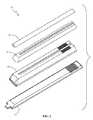
- FIG. 2is an exploded perspective view of the tissue distraction assembly of FIG. 1 ;
- FIG. 3is a front plan view of the tissue distraction assembly of FIG. 1 ;
- FIG. 4is a back plan view of the tissue distraction assembly of FIG. 1 ;
- FIG. 5is a plan view of the distal end of the tissue distraction assembly of FIG. 1 ;
- FIG. 6is a plan view of the proximal end of the tissue distraction assembly of FIG. 1 ;
- FIG. 7is a plan view of the side of the tissue distraction assembly of FIG. 1 ;
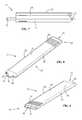
- FIGS. 8 & 9are perspective views of the an initial dilator forming part of the tissue distraction assembly of FIG. 1 ;
- FIG. 10is a front plan view of the initial dilator of FIG. 8 ;
- FIG. 11is a cross-sectional view of the initial dilator of FIG. 8 ;
- FIG. 12is a perspective view of the distal end of the initial dilator of FIG. 8 ;
- FIG. 13is a perspective view of a secondary dilator forming part of the tissue distraction assembly of FIG. 1 ;
- FIG. 14is a perspective view of the secondary dilator of FIG. 13 rotated 180 degrees;
- FIG. 15is a perspective view of the secondary dilator of FIG. 13 ;
- FIG. 16is a perspective view of the proximal end of the secondary dilator of FIG. 13 ;
- FIGS. 17-19are perspective views of a first expander forming part of the tissue distraction assembly of FIG. 1 ;
- FIGS. 20-22are perspective views of a second expander forming part of the tissue distraction assembly of FIG. 1 ;
- FIGS. 23-25are perspective views of the sequential steps in a process of assembling the tissue distraction assembly of FIG. 1 ;
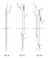
- FIGS. 26-30are plan views of the sequential steps in a process of assembling the tissue distraction assembly of FIG. 1 and in turn distracting a patient's skin tissue to establish an operative corridor according to one embodiment of the present invention.
- tissue distraction systemdisclosed herein boasts a variety of inventive features and components that warrant patent protection, both individually and in combination.
- FIGS. 1-7illustrate an example of a tissue distraction assembly 10 according to one embodiment of the present invention.
- the tissue distraction assembly 10includes a variety of sub-components dimensioned to allow for sequential dilation of a surgical tissue site in order to establish an operative corridor through a patient's skin to a surgical target site.
- the surgical target site referred to herein throughoutis an intervertebral disc space situated between two adjacent vertebrae.
- Tissue distraction assembly 10includes an initial dilator 12 , a secondary dilator 14 , a first expander 16 , and a second expander 18 .
- the tissue distraction assembly 10is provided with an overall generally oblong shape as opposed to a generally circular shape characterizing many of the sequential dilation systems currently available. This oblong shape serves to provide an initial distraction corridor spanning a target disc space, allowing the placement of pedicle screws at adjacent levels without additional tissue retraction.
- the first and second expanders 16 , 18function to bias the distraction corridor in one direction.
- the distraction corridoris biased medially (e.g. toward the patient's longitudinal midline).
- the initial dilator 12has a proximal portion 20 , a distal portion 22 , and an elongated body 24 extending therebetween.
- the initial dilator 12is formed from a pair of generally planar panels 26 connected by generally curved sides 28 , such that the initial dilator 12 has a generally oblong cross-section.
- the initial dilator 12further has a lumen 30 extending through the dilator 12 from the proximal portion 20 to the distal portion 22 .
- the proximal portion 20further includes a proximal opening 32 of the lumen 30 , and a plurality of friction elements 34 provided to enhance user control of the instrument.
- the distal portion 22includes a lead element 36 having a leading edge 38 extending along the lead element 36 .
- Lead element 36is tapered in a distal direction from the planar panels 26 to the leading edge 38 to enable the lead element 36 to advance through tissue (e.g. muscle tissue) without requiring severing or removal of that tissue.
- the distal portion 22further includes a pair of distal openings 40 positioned on either side of lead element 36 . Distal openings 40 represent the distal terminus of the lumen 30 .
- the lumen 30extends through the initial dilator 12 from the proximal opening 32 to the distal openings 40 .
- the distal portion 22 of the initial dilator 12further includes a wedge member 42 extending proximally into the lumen 30 , effectively bifurcating the lumen 30 into a pair of distal channels 44 leading to the distal openings 40 .
- the distal channels 44function to guide relevant instrumentation (e.g. K-wires) into the proper positioning within the surgical target site.
- the secondary dilator 14has a proximal portion 46 , a distal portion 48 , and an elongated body 50 extending therebetween.
- the secondary dilator 14includes a first side 52 , a second side 56 , and a pair of generally curved lateral sides 58 .
- the first side 52comprises a generally planar surface having an elongated recess 54 extending from the end of the proximal portion 46 substantially the length of the elongated body 50 and terminating near the distal portion 48 .
- the second side 56comprises a surface having a generally convex curvature.
- the convex surface of the second side 56represents one boundary of the distraction corridor because any further distraction at this point will be due to the extensions 16 , 18 , as explained in further detail below.
- Both the first and second sides 52 , 56are provided with a plurality of friction elements 60 at the proximal portion 46 provided to enhance user control of the instrument.
- the friction elements 34are provided as a plurality of ridges, however any suitable friction-inducing material and/or feature may be employed without departing from the scope of the present invention.
- the secondary dilator 14further includes a lumen 62 extending through the dilator 14 from the proximal portion 46 to the distal portion 48 .
- the lumen 62has an oblong cross-section, and is sized and dimensioned to slideably enagage the initial dilator 12 .
- the lumenfurther includes a proximal opening 64 and a distal opening 66 .
- the distal portion 48further includes a pair of generally planar surfaces 68 , 70 that are sloped or tapered from the first and second sides 54 , 56 , respectively, to the distal opening 66 of the lumen 62 .
- the tapered surfaces 68 , 70function to urge the body tissue around the path of the dilator 14 .
- the initial dilator 12may be removed if desired, and the secondary dilator 14 may act as a stand-alone cannula.
- tissue distraction system 10may be configured such that extensions are provided on one or more sides of the secondary dilator 14 , to achieve a distraction corridor of any customizable shape.
- tissue distraction assembly 10 described hereinis configured to include expanders on only one side of the secondary dilator 14 , creating a biased corridor configuration.
- First expander 16for use with the tissue distraction assembly 10 of the present invention is described.
- First expander 16includes a proximal end portion 72 , a distal end portion 74 , and an elongated body 76 extending therebetween.
- the first expander 16further includes a first side 78 comprising a generally planar surface and a second side 80 comprising a generally planar surface opposite the first side 78 .
- the first side 78includes an elongated recess 82 extending from the proximal end portion 72 substantially the length of the body portion 76 and terminates near the distal end portion 74 .
- the second side 80includes an elongated raised protrusion 84 extending from the proximal end portion 72 substantially the length of the body portion 76 and terminates near the distal end portion 74 .
- the protrusion 84is sized and dimensioned to slideably engage the elongated recess 54 of the secondary dilator 14 .
- the protrusion 84 and recess 54will have complementary shapes and sizes. Any such shape is possible, for example including but not limited to the mortise and tenon interfaces shown in the figures.
- the distal end portion 72further includes a distal tapered surface 86 that slopes in a distal direction from the first surface 78 until it forms an edge with the second surface 80 .
- the first expander 16further includes a pair of lateral tapered surfaces 88 that slopes in a lateral direction from the first surface 78 until it forms an edge with the second surface 80 .
- the lateral tapered surfaces 88extend along the length of the body portion 76 . Both the distal tapered surface 86 and lateral tapered surfaces 88 function to urge the body tissue around the path of the first expander 16 during tissue distraction, as the first expander 16 is being advanced over the initial dilator 12 to expand the operative corridor.
- Second expander 18includes a proximal end portion 90 , a distal end portion 92 , and an elongated body 94 extending therebetween.
- the second expander 18further includes a first side 96 comprising a generally convex surface and a second side 98 comprising a generally planar surface opposite the first side 96 .
- the second side 98includes an elongated raised protrusion 100 extending from the proximal end portion 90 substantially the length of the body portion 94 and terminates near the distal end portion 92 .
- the protrusion 100is sized and dimensioned to slideably engage the elongated recess 82 of the first expander 16 .
- the protrusion 100 and recess 82will have complementary shapes and sizes. Any such shape is possible, for example including but not limited to the mortise and tenon interfaces shown in the figures.
- the distal end portion 92further includes a distal tapered surface 102 that slopes in a distal direction from the first surface 96 until it forms an edge with the second surface 98 .
- the distal tapered surface 102functions to urge the body tissue around the path of the second expander 18 during tissue distraction, as the second expander 18 is being advanced over the first expander 16 to expand the operative corridor.
- FIGS. 23-25illustrate the sequential steps of assembling the tissue distraction assembly 10 .
- the first step in the distraction processis to typically run a guide to the target site.
- the surgeonwould advance a pair of K-wires to the relevant locations (i.e. pedicles) involved in the procedure in order to guide the proper placement of the dilators.
- the initial dilator 12is advanced along the K-wires such that one K-wire is in each distal channel 44 of the lumen 30 .
- the secondary dilator 14is advanced over the top of the initial dilator 12 as shown in FIG. 22 .
- first and second expanders 16 , 18may be employed as shown in FIGS. 23 and 24 .
- FIG. 28illustrates the addition of second expander 18 to the tissue distraction assembly 10 .
- the second expander 18increases the dilation distance to D 4 , where D 4 >D 3 .
- the second expander 18asymmetrically increases the distraction corridor.
- a tissue retractormay be advanced to the spine over the distraction assembly (not shown).
- the distraction assemblymay be removed and the retractor may be operated to expand to establish an operative corridor.
- the surgeonmay proceed with the desired procedure, for example, a transforaminal lumbar interbody fusion (TLIF) spinal procedure.
- TLIFtransforaminal lumbar interbody fusion
- This procedurecontinues with a facetectomy in which at least a portion of the facet joint is removed, allowing access to the intervertebral disc space.
- the disc spaceis prepared using techniques generally known in the art, including disc brushes, scrapers, etc.
- the interbody implantis then inserted into the cleaned out disc space.
- the retractormay then be removed from the patient, closing the operative corridor. The surgeon will then close the operative wound, completing the procedure.
Landscapes
- Health & Medical Sciences (AREA)
- Life Sciences & Earth Sciences (AREA)
- Surgery (AREA)
- Heart & Thoracic Surgery (AREA)
- Veterinary Medicine (AREA)
- Engineering & Computer Science (AREA)
- Biomedical Technology (AREA)
- Animal Behavior & Ethology (AREA)
- General Health & Medical Sciences (AREA)
- Public Health (AREA)
- Nuclear Medicine, Radiotherapy & Molecular Imaging (AREA)
- Medical Informatics (AREA)
- Molecular Biology (AREA)
- Orthopedic Medicine & Surgery (AREA)
- Anesthesiology (AREA)
- Hematology (AREA)
- Pathology (AREA)
- Surgical Instruments (AREA)
Abstract
Description
Claims (14)
Priority Applications (2)
| Application Number | Priority Date | Filing Date | Title |
|---|---|---|---|
| US14/532,316US9604040B1 (en) | 2008-10-15 | 2014-11-04 | System and methods for performing spinal fusion surgery |
| US15/443,652US9924933B2 (en) | 2008-10-15 | 2017-02-27 | System and methods for performing spinal fusion surgery |
Applications Claiming Priority (4)
| Application Number | Priority Date | Filing Date | Title |
|---|---|---|---|
| US10579108P | 2008-10-15 | 2008-10-15 | |
| US58021409A | 2009-10-15 | 2009-10-15 | |
| US13/831,711US8876851B1 (en) | 2008-10-15 | 2013-03-15 | Systems and methods for performing spinal fusion surgery |
| US14/532,316US9604040B1 (en) | 2008-10-15 | 2014-11-04 | System and methods for performing spinal fusion surgery |
Related Parent Applications (1)
| Application Number | Title | Priority Date | Filing Date |
|---|---|---|---|
| US13/831,711ContinuationUS8876851B1 (en) | 2008-10-15 | 2013-03-15 | Systems and methods for performing spinal fusion surgery |
Related Child Applications (1)
| Application Number | Title | Priority Date | Filing Date |
|---|---|---|---|
| US15/443,652ContinuationUS9924933B2 (en) | 2008-10-15 | 2017-02-27 | System and methods for performing spinal fusion surgery |
Publications (1)
| Publication Number | Publication Date |
|---|---|
| US9604040B1true US9604040B1 (en) | 2017-03-28 |
Family
ID=51798131
Family Applications (3)
| Application Number | Title | Priority Date | Filing Date |
|---|---|---|---|
| US13/831,711ActiveUS8876851B1 (en) | 2008-10-15 | 2013-03-15 | Systems and methods for performing spinal fusion surgery |
| US14/532,316Active2029-12-15US9604040B1 (en) | 2008-10-15 | 2014-11-04 | System and methods for performing spinal fusion surgery |
| US15/443,652ActiveUS9924933B2 (en) | 2008-10-15 | 2017-02-27 | System and methods for performing spinal fusion surgery |
Family Applications Before (1)
| Application Number | Title | Priority Date | Filing Date |
|---|---|---|---|
| US13/831,711ActiveUS8876851B1 (en) | 2008-10-15 | 2013-03-15 | Systems and methods for performing spinal fusion surgery |
Family Applications After (1)
| Application Number | Title | Priority Date | Filing Date |
|---|---|---|---|
| US15/443,652ActiveUS9924933B2 (en) | 2008-10-15 | 2017-02-27 | System and methods for performing spinal fusion surgery |
Country Status (1)
| Country | Link |
|---|---|
| US (3) | US8876851B1 (en) |
Families Citing this family (11)
| Publication number | Priority date | Publication date | Assignee | Title |
|---|---|---|---|---|
| US8876851B1 (en)* | 2008-10-15 | 2014-11-04 | Nuvasive, Inc. | Systems and methods for performing spinal fusion surgery |
| WO2012040206A1 (en) | 2010-09-20 | 2012-03-29 | Synthes Usa, Llc | Spinal access retractor |
| US9339263B2 (en)* | 2014-01-03 | 2016-05-17 | DePuy Synthes Products, Inc. | Dilation system and method |
| USD761957S1 (en) | 2014-11-11 | 2016-07-19 | Nuvasive, Inc. | Combined intradiscal insertion tool and intradiscal shim |
| US9675363B2 (en) | 2015-11-13 | 2017-06-13 | Advance Research System, Llc | Surgical tools having application for spinal surgical procedures and method of use |
| US10631842B1 (en)* | 2019-02-12 | 2020-04-28 | Edward Rustamzadeh | Lateral retraction system for minimizing muscle damage in spinal surgery |
| US12016543B2 (en)* | 2019-02-12 | 2024-06-25 | Edward Rustamzadeh | Lateral retractor system for minimizing muscle damage in spinal surgery |
| US11432810B2 (en) | 2020-05-12 | 2022-09-06 | Innovasis, Inc. | Systems and methods for surgical retraction |
| USD956225S1 (en) | 2020-05-12 | 2022-06-28 | Innovasis, Inc. | Surgical retractor |
| USD956223S1 (en) | 2020-05-12 | 2022-06-28 | Innovasis, Inc. | Surgical retractor |
| USD956224S1 (en) | 2020-05-12 | 2022-06-28 | Innovasis, Inc. | Surgical retractor |
Citations (94)
| Publication number | Priority date | Publication date | Assignee | Title |
|---|---|---|---|---|
| US208227A (en) | 1878-09-24 | Improvement in vaginal speculums | ||
| US972983A (en) | 1909-05-17 | 1910-10-18 | Lester R Lantz | Dilator. |
| US1328624A (en) | 1917-08-13 | 1920-01-20 | Frank B Graham | Dilator |
| US4545374A (en) | 1982-09-03 | 1985-10-08 | Jacobson Robert E | Method and instruments for performing a percutaneous lumbar diskectomy |
| US4573448A (en) | 1983-10-05 | 1986-03-04 | Pilling Co. | Method for decompressing herniated intervertebral discs |
| US5007902A (en) | 1988-03-09 | 1991-04-16 | B. Braun Melsungen Ag | Catheter set for plexus anesthesia |
| US5171279A (en) | 1992-03-17 | 1992-12-15 | Danek Medical | Method for subcutaneous suprafascial pedicular internal fixation |
| US5295994A (en) | 1991-11-15 | 1994-03-22 | Bonutti Peter M | Active cannulas |
| US5312417A (en) | 1992-07-29 | 1994-05-17 | Wilk Peter J | Laparoscopic cannula assembly and associated method |
| US5331975A (en) | 1990-03-02 | 1994-07-26 | Bonutti Peter M | Fluid operated retractors |
| US5342384A (en) | 1992-08-13 | 1994-08-30 | Brigham & Women's Hospital | Surgical dilator |
| US5378241A (en) | 1992-06-24 | 1995-01-03 | Haindl; Hans | Anesthesia instrument |
| US5395317A (en) | 1991-10-30 | 1995-03-07 | Smith & Nephew Dyonics, Inc. | Unilateral biportal percutaneous surgical procedure |
| US5423825A (en)* | 1992-06-10 | 1995-06-13 | Levine; Andrew S. | Spinal fusion instruments and methods |
| US5509893A (en) | 1991-06-06 | 1996-04-23 | Meditech International Pty Ltd. | Speculum |
| US5514153A (en) | 1990-03-02 | 1996-05-07 | General Surgical Innovations, Inc. | Method of dissecting tissue layers |
| US5599279A (en) | 1994-03-16 | 1997-02-04 | Gus J. Slotman | Surgical instruments and method useful for endoscopic spinal procedures |
| WO1997040878A1 (en) | 1996-05-02 | 1997-11-06 | Smith & Nephew, Inc. | Oval cannula assembly |
| US5707359A (en) | 1995-11-14 | 1998-01-13 | Bufalini; Bruno | Expanding trocar assembly |
| US5792044A (en) | 1996-03-22 | 1998-08-11 | Danek Medical, Inc. | Devices and methods for percutaneous surgery |
| US5814073A (en) | 1996-12-13 | 1998-09-29 | Bonutti; Peter M. | Method and apparatus for positioning a suture anchor |
| US5817071A (en) | 1997-01-09 | 1998-10-06 | Medtronic, Inc. | Oval-shaped cardiac cannula |
| US5888196A (en) | 1990-03-02 | 1999-03-30 | General Surgical Innovations, Inc. | Mechanically expandable arthroscopic retractors |
| US5910134A (en) | 1997-03-05 | 1999-06-08 | Fussman; Arie | Device for dilating a puncture hole in a body and for guiding the insertion of an elongated member into the body |
| JPH11290337A (en) | 1998-04-09 | 1999-10-26 | Yasuo Ito | Guide wire piercing auxiliary tool for vertebra fixing operation |
| US5976146A (en) | 1997-07-11 | 1999-11-02 | Olympus Optical Co., Ltd. | Surgical operation system and method of securing working space for surgical operation in body |
| US6152871A (en) | 1996-03-22 | 2000-11-28 | Sdgi Holdings, Inc. | Apparatus for percutaneous surgery |
| US6161047A (en) | 1998-04-30 | 2000-12-12 | Medtronic Inc. | Apparatus and method for expanding a stimulation lead body in situ |
| US6206826B1 (en) | 1997-12-18 | 2001-03-27 | Sdgi Holdings, Inc. | Devices and methods for percutaneous surgery |
| US6217509B1 (en) | 1996-03-22 | 2001-04-17 | Sdgi Holdings, Inc. | Devices and methods for percutaneous surgery |
| US6217527B1 (en) | 1998-09-30 | 2001-04-17 | Lumend, Inc. | Methods and apparatus for crossing vascular occlusions |
| US6224599B1 (en)* | 1999-05-19 | 2001-05-01 | Matthew G. Baynham | Viewable wedge distractor device |
| US6231546B1 (en) | 1998-01-13 | 2001-05-15 | Lumend, Inc. | Methods and apparatus for crossing total occlusions in blood vessels |
| US6270505B1 (en) | 1998-05-20 | 2001-08-07 | Osamu Yoshida | Endo-bag with inflation-type receiving mouth and instrument for inserting endo-bag |
| US6277094B1 (en) | 1999-04-28 | 2001-08-21 | Medtronic, Inc. | Apparatus and method for dilating ligaments and tissue by the alternating insertion of expandable tubes |
| US6292701B1 (en) | 1998-08-12 | 2001-09-18 | Medtronic Xomed, Inc. | Bipolar electrical stimulus probe with planar electrodes |
| US6325764B1 (en) | 1996-08-05 | 2001-12-04 | Becton, Dickinson And Company | Bi-level charge pulse apparatus to facilitate nerve location during peripheral nerve block procedures |
| US20010056280A1 (en) | 1992-01-07 | 2001-12-27 | Underwood Ronald A. | Systems and methods for electrosurgical spine surgery |
| US20020010392A1 (en) | 1993-03-11 | 2002-01-24 | Desai Jawahar M. | Apparatus and method for cardiac ablation |
| US6395007B1 (en) | 1999-03-16 | 2002-05-28 | American Osteomedix, Inc. | Apparatus and method for fixation of osteoporotic bone |
| US6447484B1 (en) | 1997-01-09 | 2002-09-10 | Medtronic, Inc. | Flexible disc obturator for a cannula assembly |
| US6506151B2 (en) | 1998-04-09 | 2003-01-14 | Sdgi Holdings, Inc. | Method and instrumentation for posterior interbody fusion |
| US6535759B1 (en) | 1999-04-30 | 2003-03-18 | Blue Torch Medical Technologies, Inc. | Method and device for locating and mapping nerves |
| US6564078B1 (en) | 1998-12-23 | 2003-05-13 | Nuvasive, Inc. | Nerve surveillance cannula systems |
| US6641613B2 (en) | 2002-01-30 | 2003-11-04 | Cortek, Inc. | Double dowel spinal fusion implant |
| US6641582B1 (en)* | 2000-07-06 | 2003-11-04 | Sulzer Spine-Tech Inc. | Bone preparation instruments and methods |
| US6679833B2 (en) | 1996-03-22 | 2004-01-20 | Sdgi Holdings, Inc. | Devices and methods for percutaneous surgery |
| US6719692B2 (en) | 1999-05-07 | 2004-04-13 | Aesculap Ag & Co. Kg | Rotating surgical tool |
| US20040106999A1 (en) | 2001-07-30 | 2004-06-03 | Mathews Hallett H. | Methods and devices for interbody spinal stabilization |
| US20040181231A1 (en) | 2003-03-13 | 2004-09-16 | Centerpulse Spine-Tech, Inc. | Spinal access instrument |
| US20050004593A1 (en) | 2001-10-30 | 2005-01-06 | Depuy Spine, Inc. | Non cannulated dilators |
| US6847849B2 (en) | 2000-11-15 | 2005-01-25 | Medtronic, Inc. | Minimally invasive apparatus for implanting a sacral stimulation lead |
| US6855105B2 (en) | 2001-07-11 | 2005-02-15 | Jackson, Iii Avery M. | Endoscopic pedicle probe |
| US6926728B2 (en) | 2001-07-18 | 2005-08-09 | St. Francis Medical Technologies, Inc. | Curved dilator and method |
| US6929606B2 (en) | 2001-01-29 | 2005-08-16 | Depuy Spine, Inc. | Retractor and method for spinal pedicle screw placement |
| US7008431B2 (en) | 2001-10-30 | 2006-03-07 | Depuy Spine, Inc. | Configured and sized cannula |
| US20060052669A1 (en) | 2003-01-24 | 2006-03-09 | Hart Charles C | Internal tissue retractor |
| US20060052828A1 (en) | 2004-09-08 | 2006-03-09 | Kim Daniel H | Methods for stimulating a nerve root ganglion |
| US7074226B2 (en) | 2002-09-19 | 2006-07-11 | Sdgi Holdings, Inc. | Oval dilator and retractor set and method |
| US7083625B2 (en) | 2002-06-28 | 2006-08-01 | Sdgi Holdings, Inc. | Instruments and techniques for spinal disc space preparation |
| US20060253132A1 (en) | 2005-05-06 | 2006-11-09 | International Business Machines Corporation | System and devices for the repair of a vertebral disc defect |
| US20070066977A1 (en) | 2004-10-22 | 2007-03-22 | Assell Robert L | Exchange system for axial spinal procedures |
| US7198598B2 (en) | 1996-03-22 | 2007-04-03 | Warsaw Orthopedic, Inc. | Devices and methods for percutaneous surgery |
| US7207949B2 (en) | 2003-09-25 | 2007-04-24 | Nuvasive, Inc. | Surgical access system and related methods |
| US7217246B1 (en) | 2004-06-17 | 2007-05-15 | Biomet Sports Medicine, Inc. | Method and apparatus for retaining a fixation pin to a cannula |
| US7226451B2 (en) | 2003-08-26 | 2007-06-05 | Shluzas Alan E | Minimally invasive access device and method |
| US20070233155A1 (en)* | 2005-12-07 | 2007-10-04 | Lovell John R | Device and method for holding and inserting one or more components of a pedicle screw assembly |
| US7320688B2 (en) | 1999-10-20 | 2008-01-22 | Warsaw Orthopedic, Inc. | Methods and instruments for endoscopic interbody surgical techniques |
| US20080077152A1 (en) | 2006-09-26 | 2008-03-27 | K2M, Inc. | Cervical drill guide apparatus |
| US20080091269A1 (en) | 2005-06-03 | 2008-04-17 | Zipnick Richard I | Minimally invasive apparatus to manipulate and revitalize spinal column disc |
| US7470236B1 (en) | 1999-11-24 | 2008-12-30 | Nuvasive, Inc. | Electromyography system |
| US7569061B2 (en) | 2004-11-16 | 2009-08-04 | Innovative Spinal Technologies, Inc. | Off-axis anchor guidance system |
| US7582058B1 (en) | 2002-06-26 | 2009-09-01 | Nuvasive, Inc. | Surgical access system and related methods |
| US7588588B2 (en) | 2003-10-21 | 2009-09-15 | Innovative Spinal Technologies | System and method for stabilizing of internal structures |
| US7594888B2 (en) | 2004-10-29 | 2009-09-29 | Depuy Spine, Inc. | Expandable ports and methods for minimally invasive surgery |
| US7608094B2 (en) | 2002-10-10 | 2009-10-27 | U.S. Spinal Technologies, Llc | Percutaneous facet fixation system |
| US20090270902A1 (en) | 2003-10-23 | 2009-10-29 | Trans1 Inc. | Bone dilator system and methods |
| US20100022844A1 (en) | 2005-06-22 | 2010-01-28 | Mangiardi John R | Surgical Access Instruments for Use with Spinal or Orthopedic Surgery |
| US20100081885A1 (en) | 2008-09-30 | 2010-04-01 | Aesculap Implant Systems, Inc. | Tissue retractor system |
| US20100106194A1 (en) | 2004-10-26 | 2010-04-29 | P Tech, Llc | Stabilizing a spinal anatomical structure |
| US7708761B2 (en) | 2004-11-22 | 2010-05-04 | Minsurg International, Inc. | Spinal plug for a minimally invasive facet joint fusion system |
| US20100114147A1 (en) | 2008-10-30 | 2010-05-06 | The University Of Toledo | Directional soft tissue dilator and docking pin with integrated light source for optimization of retractor placement in minimally invasive spine surgery |
| US20100280555A1 (en) | 2007-09-11 | 2010-11-04 | Kamran Aflatoon | Method of lateral facet approach, decompression and fusion using screws and staples as well as arthroplasty |
| US7837713B2 (en) | 2004-11-22 | 2010-11-23 | Minsurg International, Inc. | Methods and surgical kits for minimally-invasive facet joint fusion |
| KR20100123083A (en) | 2009-05-14 | 2010-11-24 | 주식회사 위노바 | Instrument for insertion of working sleeve for spinal surgery |
| US20100331891A1 (en) | 2009-06-24 | 2010-12-30 | Interventional Spine, Inc. | System and method for spinal fixation |
| US20110077685A1 (en) | 2009-09-30 | 2011-03-31 | Warsaw Orthopedic, Inc. | Systems and methods and methods for minimally invasive facet fusion |
| US7959564B2 (en) | 2006-07-08 | 2011-06-14 | Stephen Ritland | Pedicle seeker and retractor, and methods of use |
| US20110144687A1 (en) | 2009-12-10 | 2011-06-16 | Kleiner Jeffrey | Lateral Based Retractor System |
| US7981029B2 (en) | 2002-06-26 | 2011-07-19 | Warsaw Orthopedic, Inc. | Instruments and methods for minimally invasive tissue retraction and surgery |
| US20110208226A1 (en) | 2007-10-05 | 2011-08-25 | Fatone Peter | Dilation system and method of using the same |
| US8043212B1 (en)* | 2004-11-05 | 2011-10-25 | Zimmer Spine, Inc. | Methods for treating cervical vertebrae through an access device |
| US8075591B2 (en) | 2004-11-09 | 2011-12-13 | Depuy Spine, Inc. | Minimally invasive spinal fixation guide systems and methods |
| US8142507B2 (en) | 2006-11-16 | 2012-03-27 | Rex Medical, L.P. | Spinal implant and method of use |
Family Cites Families (1)
| Publication number | Priority date | Publication date | Assignee | Title |
|---|---|---|---|---|
| US8876851B1 (en)* | 2008-10-15 | 2014-11-04 | Nuvasive, Inc. | Systems and methods for performing spinal fusion surgery |
- 2013
- 2013-03-15USUS13/831,711patent/US8876851B1/enactiveActive
- 2014
- 2014-11-04USUS14/532,316patent/US9604040B1/enactiveActive
- 2017
- 2017-02-27USUS15/443,652patent/US9924933B2/enactiveActive
Patent Citations (113)
| Publication number | Priority date | Publication date | Assignee | Title |
|---|---|---|---|---|
| US208227A (en) | 1878-09-24 | Improvement in vaginal speculums | ||
| US972983A (en) | 1909-05-17 | 1910-10-18 | Lester R Lantz | Dilator. |
| US1328624A (en) | 1917-08-13 | 1920-01-20 | Frank B Graham | Dilator |
| US4545374A (en) | 1982-09-03 | 1985-10-08 | Jacobson Robert E | Method and instruments for performing a percutaneous lumbar diskectomy |
| US4573448A (en) | 1983-10-05 | 1986-03-04 | Pilling Co. | Method for decompressing herniated intervertebral discs |
| US5007902A (en) | 1988-03-09 | 1991-04-16 | B. Braun Melsungen Ag | Catheter set for plexus anesthesia |
| US5514153A (en) | 1990-03-02 | 1996-05-07 | General Surgical Innovations, Inc. | Method of dissecting tissue layers |
| US5331975A (en) | 1990-03-02 | 1994-07-26 | Bonutti Peter M | Fluid operated retractors |
| US5888196A (en) | 1990-03-02 | 1999-03-30 | General Surgical Innovations, Inc. | Mechanically expandable arthroscopic retractors |
| US7311719B2 (en) | 1990-03-02 | 2007-12-25 | General Surgical Innovations, Inc. | Active cannulas |
| US5509893A (en) | 1991-06-06 | 1996-04-23 | Meditech International Pty Ltd. | Speculum |
| US5762629A (en) | 1991-10-30 | 1998-06-09 | Smith & Nephew, Inc. | Oval cannula assembly and method of use |
| US5395317A (en) | 1991-10-30 | 1995-03-07 | Smith & Nephew Dyonics, Inc. | Unilateral biportal percutaneous surgical procedure |
| US5295994A (en) | 1991-11-15 | 1994-03-22 | Bonutti Peter M | Active cannulas |
| US20010056280A1 (en) | 1992-01-07 | 2001-12-27 | Underwood Ronald A. | Systems and methods for electrosurgical spine surgery |
| US5171279A (en) | 1992-03-17 | 1992-12-15 | Danek Medical | Method for subcutaneous suprafascial pedicular internal fixation |
| US5423825A (en)* | 1992-06-10 | 1995-06-13 | Levine; Andrew S. | Spinal fusion instruments and methods |
| US5378241A (en) | 1992-06-24 | 1995-01-03 | Haindl; Hans | Anesthesia instrument |
| US5312417A (en) | 1992-07-29 | 1994-05-17 | Wilk Peter J | Laparoscopic cannula assembly and associated method |
| US5342384A (en) | 1992-08-13 | 1994-08-30 | Brigham & Women's Hospital | Surgical dilator |
| US20020010392A1 (en) | 1993-03-11 | 2002-01-24 | Desai Jawahar M. | Apparatus and method for cardiac ablation |
| US5599279A (en) | 1994-03-16 | 1997-02-04 | Gus J. Slotman | Surgical instruments and method useful for endoscopic spinal procedures |
| US5707359A (en) | 1995-11-14 | 1998-01-13 | Bufalini; Bruno | Expanding trocar assembly |
| US5792044A (en) | 1996-03-22 | 1998-08-11 | Danek Medical, Inc. | Devices and methods for percutaneous surgery |
| US6217509B1 (en) | 1996-03-22 | 2001-04-17 | Sdgi Holdings, Inc. | Devices and methods for percutaneous surgery |
| US6152871A (en) | 1996-03-22 | 2000-11-28 | Sdgi Holdings, Inc. | Apparatus for percutaneous surgery |
| US7198598B2 (en) | 1996-03-22 | 2007-04-03 | Warsaw Orthopedic, Inc. | Devices and methods for percutaneous surgery |
| US6679833B2 (en) | 1996-03-22 | 2004-01-20 | Sdgi Holdings, Inc. | Devices and methods for percutaneous surgery |
| US6007487A (en) | 1996-03-22 | 1999-12-28 | Sdgi Holdings, Inc. | Tissue retractor for use through a cannula |
| US20030139648A1 (en) | 1996-03-22 | 2003-07-24 | Foley Kevin Thomas | Devices and methods for percutaneous surgery |
| US6425859B1 (en) | 1996-03-22 | 2002-07-30 | Sdgi Holdings, Inc. | Cannula and a retractor for percutaneous surgery |
| US5902231A (en) | 1996-03-22 | 1999-05-11 | Sdgi Holdings, Inc. | Devices and methods for percutaneous surgery |
| US6520907B1 (en) | 1996-03-22 | 2003-02-18 | Sdgi Holdings, Inc. | Methods for accessing the spinal column |
| US7993378B2 (en) | 1996-03-22 | 2011-08-09 | Warsaw Orthopedic, IN. | Methods for percutaneous spinal surgery |
| WO1997040878A1 (en) | 1996-05-02 | 1997-11-06 | Smith & Nephew, Inc. | Oval cannula assembly |
| US6325764B1 (en) | 1996-08-05 | 2001-12-04 | Becton, Dickinson And Company | Bi-level charge pulse apparatus to facilitate nerve location during peripheral nerve block procedures |
| US5814073A (en) | 1996-12-13 | 1998-09-29 | Bonutti; Peter M. | Method and apparatus for positioning a suture anchor |
| US6645194B2 (en) | 1997-01-09 | 2003-11-11 | Medtronic, Inc. | Flexible disc obturator for a cannula assembly |
| US5817071A (en) | 1997-01-09 | 1998-10-06 | Medtronic, Inc. | Oval-shaped cardiac cannula |
| US7276055B2 (en) | 1997-01-09 | 2007-10-02 | Medtronic, Inc. | Oval-shaped cardiac cannula |
| US20070083161A1 (en) | 1997-01-09 | 2007-04-12 | Medtronic, Inc. | Oval-Shaped Cardiac Cannula |
| US6447484B1 (en) | 1997-01-09 | 2002-09-10 | Medtronic, Inc. | Flexible disc obturator for a cannula assembly |
| US6146371A (en) | 1997-01-09 | 2000-11-14 | Medtronic, Inc. | Oval-shaped cardiac cannula |
| US5910134A (en) | 1997-03-05 | 1999-06-08 | Fussman; Arie | Device for dilating a puncture hole in a body and for guiding the insertion of an elongated member into the body |
| US5976146A (en) | 1997-07-11 | 1999-11-02 | Olympus Optical Co., Ltd. | Surgical operation system and method of securing working space for surgical operation in body |
| US6206826B1 (en) | 1997-12-18 | 2001-03-27 | Sdgi Holdings, Inc. | Devices and methods for percutaneous surgery |
| US6231546B1 (en) | 1998-01-13 | 2001-05-15 | Lumend, Inc. | Methods and apparatus for crossing total occlusions in blood vessels |
| US6221049B1 (en) | 1998-01-13 | 2001-04-24 | Lumend, Inc. | Methods and apparatus for crossing vascular occlusions |
| US6514217B1 (en) | 1998-01-13 | 2003-02-04 | Lumend, Inc. | Methods and apparatus for treating vascular occlusions |
| JPH11290337A (en) | 1998-04-09 | 1999-10-26 | Yasuo Ito | Guide wire piercing auxiliary tool for vertebra fixing operation |
| US6506151B2 (en) | 1998-04-09 | 2003-01-14 | Sdgi Holdings, Inc. | Method and instrumentation for posterior interbody fusion |
| US6161047A (en) | 1998-04-30 | 2000-12-12 | Medtronic Inc. | Apparatus and method for expanding a stimulation lead body in situ |
| US6270505B1 (en) | 1998-05-20 | 2001-08-07 | Osamu Yoshida | Endo-bag with inflation-type receiving mouth and instrument for inserting endo-bag |
| US6292701B1 (en) | 1998-08-12 | 2001-09-18 | Medtronic Xomed, Inc. | Bipolar electrical stimulus probe with planar electrodes |
| US6217527B1 (en) | 1998-09-30 | 2001-04-17 | Lumend, Inc. | Methods and apparatus for crossing vascular occlusions |
| US6564078B1 (en) | 1998-12-23 | 2003-05-13 | Nuvasive, Inc. | Nerve surveillance cannula systems |
| US6395007B1 (en) | 1999-03-16 | 2002-05-28 | American Osteomedix, Inc. | Apparatus and method for fixation of osteoporotic bone |
| US6277094B1 (en) | 1999-04-28 | 2001-08-21 | Medtronic, Inc. | Apparatus and method for dilating ligaments and tissue by the alternating insertion of expandable tubes |
| US6535759B1 (en) | 1999-04-30 | 2003-03-18 | Blue Torch Medical Technologies, Inc. | Method and device for locating and mapping nerves |
| US6719692B2 (en) | 1999-05-07 | 2004-04-13 | Aesculap Ag & Co. Kg | Rotating surgical tool |
| US6224599B1 (en)* | 1999-05-19 | 2001-05-01 | Matthew G. Baynham | Viewable wedge distractor device |
| US7320688B2 (en) | 1999-10-20 | 2008-01-22 | Warsaw Orthopedic, Inc. | Methods and instruments for endoscopic interbody surgical techniques |
| US7470236B1 (en) | 1999-11-24 | 2008-12-30 | Nuvasive, Inc. | Electromyography system |
| US6641582B1 (en)* | 2000-07-06 | 2003-11-04 | Sulzer Spine-Tech Inc. | Bone preparation instruments and methods |
| US6847849B2 (en) | 2000-11-15 | 2005-01-25 | Medtronic, Inc. | Minimally invasive apparatus for implanting a sacral stimulation lead |
| US6929606B2 (en) | 2001-01-29 | 2005-08-16 | Depuy Spine, Inc. | Retractor and method for spinal pedicle screw placement |
| US6855105B2 (en) | 2001-07-11 | 2005-02-15 | Jackson, Iii Avery M. | Endoscopic pedicle probe |
| US6926728B2 (en) | 2001-07-18 | 2005-08-09 | St. Francis Medical Technologies, Inc. | Curved dilator and method |
| US20040106999A1 (en) | 2001-07-30 | 2004-06-03 | Mathews Hallett H. | Methods and devices for interbody spinal stabilization |
| US20050004593A1 (en) | 2001-10-30 | 2005-01-06 | Depuy Spine, Inc. | Non cannulated dilators |
| US6916330B2 (en) | 2001-10-30 | 2005-07-12 | Depuy Spine, Inc. | Non cannulated dilators |
| US7008431B2 (en) | 2001-10-30 | 2006-03-07 | Depuy Spine, Inc. | Configured and sized cannula |
| US20100222824A1 (en) | 2001-10-30 | 2010-09-02 | Depuy Spine, Inc. | Configured and sized cannula |
| US6641613B2 (en) | 2002-01-30 | 2003-11-04 | Cortek, Inc. | Double dowel spinal fusion implant |
| US7981029B2 (en) | 2002-06-26 | 2011-07-19 | Warsaw Orthopedic, Inc. | Instruments and methods for minimally invasive tissue retraction and surgery |
| US7582058B1 (en) | 2002-06-26 | 2009-09-01 | Nuvasive, Inc. | Surgical access system and related methods |
| US7083625B2 (en) | 2002-06-28 | 2006-08-01 | Sdgi Holdings, Inc. | Instruments and techniques for spinal disc space preparation |
| US7074226B2 (en) | 2002-09-19 | 2006-07-11 | Sdgi Holdings, Inc. | Oval dilator and retractor set and method |
| US7618431B2 (en) | 2002-09-19 | 2009-11-17 | Warsaw Orthopedic, Inc. | Oval dilator and retractor set and method |
| US7608094B2 (en) | 2002-10-10 | 2009-10-27 | U.S. Spinal Technologies, Llc | Percutaneous facet fixation system |
| US20060052669A1 (en) | 2003-01-24 | 2006-03-09 | Hart Charles C | Internal tissue retractor |
| US20040181231A1 (en) | 2003-03-13 | 2004-09-16 | Centerpulse Spine-Tech, Inc. | Spinal access instrument |
| US7226451B2 (en) | 2003-08-26 | 2007-06-05 | Shluzas Alan E | Minimally invasive access device and method |
| US7207949B2 (en) | 2003-09-25 | 2007-04-24 | Nuvasive, Inc. | Surgical access system and related methods |
| US7588588B2 (en) | 2003-10-21 | 2009-09-15 | Innovative Spinal Technologies | System and method for stabilizing of internal structures |
| US20090270902A1 (en) | 2003-10-23 | 2009-10-29 | Trans1 Inc. | Bone dilator system and methods |
| US7217246B1 (en) | 2004-06-17 | 2007-05-15 | Biomet Sports Medicine, Inc. | Method and apparatus for retaining a fixation pin to a cannula |
| US20060052828A1 (en) | 2004-09-08 | 2006-03-09 | Kim Daniel H | Methods for stimulating a nerve root ganglion |
| US20070066977A1 (en) | 2004-10-22 | 2007-03-22 | Assell Robert L | Exchange system for axial spinal procedures |
| US20100106194A1 (en) | 2004-10-26 | 2010-04-29 | P Tech, Llc | Stabilizing a spinal anatomical structure |
| US7594888B2 (en) | 2004-10-29 | 2009-09-29 | Depuy Spine, Inc. | Expandable ports and methods for minimally invasive surgery |
| US8043212B1 (en)* | 2004-11-05 | 2011-10-25 | Zimmer Spine, Inc. | Methods for treating cervical vertebrae through an access device |
| US8075591B2 (en) | 2004-11-09 | 2011-12-13 | Depuy Spine, Inc. | Minimally invasive spinal fixation guide systems and methods |
| US7569061B2 (en) | 2004-11-16 | 2009-08-04 | Innovative Spinal Technologies, Inc. | Off-axis anchor guidance system |
| US7708761B2 (en) | 2004-11-22 | 2010-05-04 | Minsurg International, Inc. | Spinal plug for a minimally invasive facet joint fusion system |
| US7837713B2 (en) | 2004-11-22 | 2010-11-23 | Minsurg International, Inc. | Methods and surgical kits for minimally-invasive facet joint fusion |
| US20100222829A1 (en) | 2004-11-22 | 2010-09-02 | Petersen David A | Spinal plug for a minimally invasive joint fusion system |
| US20060253132A1 (en) | 2005-05-06 | 2006-11-09 | International Business Machines Corporation | System and devices for the repair of a vertebral disc defect |
| US20080091269A1 (en) | 2005-06-03 | 2008-04-17 | Zipnick Richard I | Minimally invasive apparatus to manipulate and revitalize spinal column disc |
| US20100022844A1 (en) | 2005-06-22 | 2010-01-28 | Mangiardi John R | Surgical Access Instruments for Use with Spinal or Orthopedic Surgery |
| US20070233155A1 (en)* | 2005-12-07 | 2007-10-04 | Lovell John R | Device and method for holding and inserting one or more components of a pedicle screw assembly |
| US7959564B2 (en) | 2006-07-08 | 2011-06-14 | Stephen Ritland | Pedicle seeker and retractor, and methods of use |
| US20080077152A1 (en) | 2006-09-26 | 2008-03-27 | K2M, Inc. | Cervical drill guide apparatus |
| US8142507B2 (en) | 2006-11-16 | 2012-03-27 | Rex Medical, L.P. | Spinal implant and method of use |
| US20100280555A1 (en) | 2007-09-11 | 2010-11-04 | Kamran Aflatoon | Method of lateral facet approach, decompression and fusion using screws and staples as well as arthroplasty |
| US20110208226A1 (en) | 2007-10-05 | 2011-08-25 | Fatone Peter | Dilation system and method of using the same |
| US20100081885A1 (en) | 2008-09-30 | 2010-04-01 | Aesculap Implant Systems, Inc. | Tissue retractor system |
| US20100114147A1 (en) | 2008-10-30 | 2010-05-06 | The University Of Toledo | Directional soft tissue dilator and docking pin with integrated light source for optimization of retractor placement in minimally invasive spine surgery |
| KR20100123083A (en) | 2009-05-14 | 2010-11-24 | 주식회사 위노바 | Instrument for insertion of working sleeve for spinal surgery |
| US20100331891A1 (en) | 2009-06-24 | 2010-12-30 | Interventional Spine, Inc. | System and method for spinal fixation |
| US20110077685A1 (en) | 2009-09-30 | 2011-03-31 | Warsaw Orthopedic, Inc. | Systems and methods and methods for minimally invasive facet fusion |
| WO2011044484A1 (en) | 2009-10-09 | 2011-04-14 | P Tech, Llc | Stabilizing a spinal anatomical structure |
| US20110144687A1 (en) | 2009-12-10 | 2011-06-16 | Kleiner Jeffrey | Lateral Based Retractor System |
Also Published As
| Publication number | Publication date |
|---|---|
| US20170164937A1 (en) | 2017-06-15 |
| US8876851B1 (en) | 2014-11-04 |
| US9924933B2 (en) | 2018-03-27 |
Similar Documents
| Publication | Publication Date | Title |
|---|---|---|
| US9604040B1 (en) | System and methods for performing spinal fusion surgery | |
| US11717421B2 (en) | Lateral insertion spinal implant | |
| US12396863B2 (en) | Methods and apparatus for performing spine surgery | |
| EP1978900B1 (en) | Interspinous process spacer | |
| US9987142B2 (en) | Fixation devices for anterior lumbar or cervical interbody fusion | |
| US9084637B2 (en) | Intervertebral implant | |
| US20120029639A1 (en) | Interbody spinal implants and insertion techniques | |
| US9770236B2 (en) | Spinal surgery distraction with an integrated retractor | |
| US9463052B2 (en) | Access assembly for anterior and lateral spinal procedures | |
| US9839449B2 (en) | Translational plate and compressor instrument | |
| US11389209B2 (en) | Surgical plating systems, devices, and related methods | |
| US20230355408A1 (en) | Systems and methods for treating a sacroiliac joint | |
| US20150105624A1 (en) | Surgical access system and related methods | |
| US20090024171A1 (en) | Anatomical Anterior Vertebral Plating System | |
| US8292923B1 (en) | Systems and methods for treating spinal stenosis | |
| EP2061387B1 (en) | A bone plate for fixation to a patient's vertebrae | |
| US20250275791A1 (en) | Pedicle based retractor with screw gate | |
| AU2012244234A1 (en) | A device for treating the spine |
Legal Events
| Date | Code | Title | Description |
|---|---|---|---|
| AS | Assignment | Owner name:NUVASIVE, INC., CALIFORNIA Free format text:ASSIGNMENT OF ASSIGNORS INTEREST;ASSIGNORS:WOOLLEY, TROY;LOVELL, NATHAN;SERRA, MICHAEL;REEL/FRAME:034815/0751 Effective date:20100202 | |
| AS | Assignment | Owner name:BANK OF AMERICA, N.A., AS ADMINISTRATIVE AGENT, CALIFORNIA Free format text:NOTICE OF GRANT OF SECURITY INTEREST IN PATENTS;ASSIGNORS:NUVASIVE, INC.;IMPULSE MONITORING, INC.;REEL/FRAME:040634/0404 Effective date:20160208 Owner name:BANK OF AMERICA, N.A., AS ADMINISTRATIVE AGENT, CA Free format text:NOTICE OF GRANT OF SECURITY INTEREST IN PATENTS;ASSIGNORS:NUVASIVE, INC.;IMPULSE MONITORING, INC.;REEL/FRAME:040634/0404 Effective date:20160208 | |
| STCF | Information on status: patent grant | Free format text:PATENTED CASE | |
| AS | Assignment | Owner name:BANK OF AMERICA, N.A., AS ADMINISTRATIVE AGENT, TE Free format text:NOTICE OF GRANT OF SECURITY INTEREST IN PATENTS;ASSIGNORS:NUVASIVE, INC.;BIOTRONIC NATIONAL, LLC;NUVASIVE CLINICAL SERVICES MONITORING, INC.;AND OTHERS;REEL/FRAME:042490/0236 Effective date:20170425 Owner name:BANK OF AMERICA, N.A., AS ADMINISTRATIVE AGENT, TEXAS Free format text:NOTICE OF GRANT OF SECURITY INTEREST IN PATENTS;ASSIGNORS:NUVASIVE, INC.;BIOTRONIC NATIONAL, LLC;NUVASIVE CLINICAL SERVICES MONITORING, INC.;AND OTHERS;REEL/FRAME:042490/0236 Effective date:20170425 | |
| AS | Assignment | Owner name:BANK OF AMERICA, N.A., AS ADMINISTRATIVE AGENT, NORTH CAROLINA Free format text:SECURITY INTEREST;ASSIGNORS:NUVASIVE, INC.;NUVASIVE CLINICAL SERVICES MONITORING, INC.;NUVASIVE CLINICAL SERVICES, INC.;AND OTHERS;REEL/FRAME:052918/0595 Effective date:20200224 | |
| MAFP | Maintenance fee payment | Free format text:PAYMENT OF MAINTENANCE FEE, 4TH YEAR, LARGE ENTITY (ORIGINAL EVENT CODE: M1551); ENTITY STATUS OF PATENT OWNER: LARGE ENTITY Year of fee payment:4 | |
| MAFP | Maintenance fee payment | Free format text:PAYMENT OF MAINTENANCE FEE, 8TH YEAR, LARGE ENTITY (ORIGINAL EVENT CODE: M1552); ENTITY STATUS OF PATENT OWNER: LARGE ENTITY Year of fee payment:8 |