US9603718B2 - Spacer with temporary fixation plate - Google Patents
Spacer with temporary fixation plateDownload PDFInfo
- Publication number
- US9603718B2 US9603718B2US14/634,107US201514634107AUS9603718B2US 9603718 B2US9603718 B2US 9603718B2US 201514634107 AUS201514634107 AUS 201514634107AUS 9603718 B2US9603718 B2US 9603718B2
- Authority
- US
- United States
- Prior art keywords
- thread
- spacer
- coupling aperture
- plate
- aperture
- Prior art date
- Legal status (The legal status is an assumption and is not a legal conclusion. Google has not performed a legal analysis and makes no representation as to the accuracy of the status listed.)
- Active
Links
Images


Classifications
- A—HUMAN NECESSITIES
- A61—MEDICAL OR VETERINARY SCIENCE; HYGIENE
- A61F—FILTERS IMPLANTABLE INTO BLOOD VESSELS; PROSTHESES; DEVICES PROVIDING PATENCY TO, OR PREVENTING COLLAPSING OF, TUBULAR STRUCTURES OF THE BODY, e.g. STENTS; ORTHOPAEDIC, NURSING OR CONTRACEPTIVE DEVICES; FOMENTATION; TREATMENT OR PROTECTION OF EYES OR EARS; BANDAGES, DRESSINGS OR ABSORBENT PADS; FIRST-AID KITS
- A61F2/00—Filters implantable into blood vessels; Prostheses, i.e. artificial substitutes or replacements for parts of the body; Appliances for connecting them with the body; Devices providing patency to, or preventing collapsing of, tubular structures of the body, e.g. stents
- A61F2/02—Prostheses implantable into the body
- A61F2/30—Joints
- A61F2/44—Joints for the spine, e.g. vertebrae, spinal discs
- A61F2/4455—Joints for the spine, e.g. vertebrae, spinal discs for the fusion of spinal bodies, e.g. intervertebral fusion of adjacent spinal bodies, e.g. fusion cages
- A61F2/447—Joints for the spine, e.g. vertebrae, spinal discs for the fusion of spinal bodies, e.g. intervertebral fusion of adjacent spinal bodies, e.g. fusion cages substantially parallelepipedal, e.g. having a rectangular or trapezoidal cross-section
- A—HUMAN NECESSITIES
- A61—MEDICAL OR VETERINARY SCIENCE; HYGIENE
- A61B—DIAGNOSIS; SURGERY; IDENTIFICATION
- A61B17/00—Surgical instruments, devices or methods
- A61B17/56—Surgical instruments or methods for treatment of bones or joints; Devices specially adapted therefor
- A61B17/58—Surgical instruments or methods for treatment of bones or joints; Devices specially adapted therefor for osteosynthesis, e.g. bone plates, screws or setting implements
- A61B17/68—Internal fixation devices, including fasteners and spinal fixators, even if a part thereof projects from the skin
- A61B17/70—Spinal positioners or stabilisers, e.g. stabilisers comprising fluid filler in an implant
- A61B17/7059—Cortical plates
- A—HUMAN NECESSITIES
- A61—MEDICAL OR VETERINARY SCIENCE; HYGIENE
- A61B—DIAGNOSIS; SURGERY; IDENTIFICATION
- A61B17/00—Surgical instruments, devices or methods
- A61B17/56—Surgical instruments or methods for treatment of bones or joints; Devices specially adapted therefor
- A61B17/58—Surgical instruments or methods for treatment of bones or joints; Devices specially adapted therefor for osteosynthesis, e.g. bone plates, screws or setting implements
- A61B17/68—Internal fixation devices, including fasteners and spinal fixators, even if a part thereof projects from the skin
- A61B17/84—Fasteners therefor or fasteners being internal fixation devices
- A61B17/86—Pins or screws or threaded wires; nuts therefor
- A61B17/8625—Shanks, i.e. parts contacting bone tissue
- A—HUMAN NECESSITIES
- A61—MEDICAL OR VETERINARY SCIENCE; HYGIENE
- A61F—FILTERS IMPLANTABLE INTO BLOOD VESSELS; PROSTHESES; DEVICES PROVIDING PATENCY TO, OR PREVENTING COLLAPSING OF, TUBULAR STRUCTURES OF THE BODY, e.g. STENTS; ORTHOPAEDIC, NURSING OR CONTRACEPTIVE DEVICES; FOMENTATION; TREATMENT OR PROTECTION OF EYES OR EARS; BANDAGES, DRESSINGS OR ABSORBENT PADS; FIRST-AID KITS
- A61F2/00—Filters implantable into blood vessels; Prostheses, i.e. artificial substitutes or replacements for parts of the body; Appliances for connecting them with the body; Devices providing patency to, or preventing collapsing of, tubular structures of the body, e.g. stents
- A61F2/02—Prostheses implantable into the body
- A61F2/30—Joints
- A61F2/44—Joints for the spine, e.g. vertebrae, spinal discs
- A61F2/4455—Joints for the spine, e.g. vertebrae, spinal discs for the fusion of spinal bodies, e.g. intervertebral fusion of adjacent spinal bodies, e.g. fusion cages
- A61F2/446—Joints for the spine, e.g. vertebrae, spinal discs for the fusion of spinal bodies, e.g. intervertebral fusion of adjacent spinal bodies, e.g. fusion cages having a circular or elliptical cross-section substantially parallel to the axis of the spine, e.g. cylinders or frustocones
- A—HUMAN NECESSITIES
- A61—MEDICAL OR VETERINARY SCIENCE; HYGIENE
- A61F—FILTERS IMPLANTABLE INTO BLOOD VESSELS; PROSTHESES; DEVICES PROVIDING PATENCY TO, OR PREVENTING COLLAPSING OF, TUBULAR STRUCTURES OF THE BODY, e.g. STENTS; ORTHOPAEDIC, NURSING OR CONTRACEPTIVE DEVICES; FOMENTATION; TREATMENT OR PROTECTION OF EYES OR EARS; BANDAGES, DRESSINGS OR ABSORBENT PADS; FIRST-AID KITS
- A61F2/00—Filters implantable into blood vessels; Prostheses, i.e. artificial substitutes or replacements for parts of the body; Appliances for connecting them with the body; Devices providing patency to, or preventing collapsing of, tubular structures of the body, e.g. stents
- A61F2/02—Prostheses implantable into the body
- A61F2/30—Joints
- A61F2/44—Joints for the spine, e.g. vertebrae, spinal discs
- A61F2/4455—Joints for the spine, e.g. vertebrae, spinal discs for the fusion of spinal bodies, e.g. intervertebral fusion of adjacent spinal bodies, e.g. fusion cages
- A61F2/4465—Joints for the spine, e.g. vertebrae, spinal discs for the fusion of spinal bodies, e.g. intervertebral fusion of adjacent spinal bodies, e.g. fusion cages having a circular or kidney shaped cross-section substantially perpendicular to the axis of the spine
- A—HUMAN NECESSITIES
- A61—MEDICAL OR VETERINARY SCIENCE; HYGIENE
- A61F—FILTERS IMPLANTABLE INTO BLOOD VESSELS; PROSTHESES; DEVICES PROVIDING PATENCY TO, OR PREVENTING COLLAPSING OF, TUBULAR STRUCTURES OF THE BODY, e.g. STENTS; ORTHOPAEDIC, NURSING OR CONTRACEPTIVE DEVICES; FOMENTATION; TREATMENT OR PROTECTION OF EYES OR EARS; BANDAGES, DRESSINGS OR ABSORBENT PADS; FIRST-AID KITS
- A61F2/00—Filters implantable into blood vessels; Prostheses, i.e. artificial substitutes or replacements for parts of the body; Appliances for connecting them with the body; Devices providing patency to, or preventing collapsing of, tubular structures of the body, e.g. stents
- A61F2/02—Prostheses implantable into the body
- A61F2/30—Joints
- A61F2002/30001—Additional features of subject-matter classified in A61F2/28, A61F2/30 and subgroups thereof
- A61F2002/30316—The prosthesis having different structural features at different locations within the same prosthesis; Connections between prosthetic parts; Special structural features of bone or joint prostheses not otherwise provided for
- A61F2002/30535—Special structural features of bone or joint prostheses not otherwise provided for
- A61F2002/30593—Special structural features of bone or joint prostheses not otherwise provided for hollow
- A—HUMAN NECESSITIES
- A61—MEDICAL OR VETERINARY SCIENCE; HYGIENE
- A61F—FILTERS IMPLANTABLE INTO BLOOD VESSELS; PROSTHESES; DEVICES PROVIDING PATENCY TO, OR PREVENTING COLLAPSING OF, TUBULAR STRUCTURES OF THE BODY, e.g. STENTS; ORTHOPAEDIC, NURSING OR CONTRACEPTIVE DEVICES; FOMENTATION; TREATMENT OR PROTECTION OF EYES OR EARS; BANDAGES, DRESSINGS OR ABSORBENT PADS; FIRST-AID KITS
- A61F2/00—Filters implantable into blood vessels; Prostheses, i.e. artificial substitutes or replacements for parts of the body; Appliances for connecting them with the body; Devices providing patency to, or preventing collapsing of, tubular structures of the body, e.g. stents
- A61F2/02—Prostheses implantable into the body
- A61F2/30—Joints
- A61F2002/30001—Additional features of subject-matter classified in A61F2/28, A61F2/30 and subgroups thereof
- A61F2002/30667—Features concerning an interaction with the environment or a particular use of the prosthesis
- A61F2002/30672—Features concerning an interaction with the environment or a particular use of the prosthesis temporary
- A—HUMAN NECESSITIES
- A61—MEDICAL OR VETERINARY SCIENCE; HYGIENE
- A61F—FILTERS IMPLANTABLE INTO BLOOD VESSELS; PROSTHESES; DEVICES PROVIDING PATENCY TO, OR PREVENTING COLLAPSING OF, TUBULAR STRUCTURES OF THE BODY, e.g. STENTS; ORTHOPAEDIC, NURSING OR CONTRACEPTIVE DEVICES; FOMENTATION; TREATMENT OR PROTECTION OF EYES OR EARS; BANDAGES, DRESSINGS OR ABSORBENT PADS; FIRST-AID KITS
- A61F2/00—Filters implantable into blood vessels; Prostheses, i.e. artificial substitutes or replacements for parts of the body; Appliances for connecting them with the body; Devices providing patency to, or preventing collapsing of, tubular structures of the body, e.g. stents
- A61F2/02—Prostheses implantable into the body
- A61F2/30—Joints
- A61F2/44—Joints for the spine, e.g. vertebrae, spinal discs
- A61F2/442—Intervertebral or spinal discs, e.g. resilient
- A61F2002/4435—Support means or repair of the natural disc wall, i.e. annulus, e.g. using plates, membranes or meshes
- A—HUMAN NECESSITIES
- A61—MEDICAL OR VETERINARY SCIENCE; HYGIENE
- A61F—FILTERS IMPLANTABLE INTO BLOOD VESSELS; PROSTHESES; DEVICES PROVIDING PATENCY TO, OR PREVENTING COLLAPSING OF, TUBULAR STRUCTURES OF THE BODY, e.g. STENTS; ORTHOPAEDIC, NURSING OR CONTRACEPTIVE DEVICES; FOMENTATION; TREATMENT OR PROTECTION OF EYES OR EARS; BANDAGES, DRESSINGS OR ABSORBENT PADS; FIRST-AID KITS
- A61F2220/00—Fixations or connections for prostheses classified in groups A61F2/00 - A61F2/26 or A61F2/82 or A61F9/00 or A61F11/00 or subgroups thereof
- A61F2220/0008—Fixation appliances for connecting prostheses to the body
- A61F2220/0016—Fixation appliances for connecting prostheses to the body with sharp anchoring protrusions, e.g. barbs, pins, spikes
- A—HUMAN NECESSITIES
- A61—MEDICAL OR VETERINARY SCIENCE; HYGIENE
- A61F—FILTERS IMPLANTABLE INTO BLOOD VESSELS; PROSTHESES; DEVICES PROVIDING PATENCY TO, OR PREVENTING COLLAPSING OF, TUBULAR STRUCTURES OF THE BODY, e.g. STENTS; ORTHOPAEDIC, NURSING OR CONTRACEPTIVE DEVICES; FOMENTATION; TREATMENT OR PROTECTION OF EYES OR EARS; BANDAGES, DRESSINGS OR ABSORBENT PADS; FIRST-AID KITS
- A61F2220/00—Fixations or connections for prostheses classified in groups A61F2/00 - A61F2/26 or A61F2/82 or A61F9/00 or A61F11/00 or subgroups thereof
- A61F2220/0025—Connections or couplings between prosthetic parts, e.g. between modular parts; Connecting elements
- A61F2220/0041—Connections or couplings between prosthetic parts, e.g. between modular parts; Connecting elements using additional screws, bolts, dowels or rivets, e.g. connecting screws
Definitions
- the inventiongenerally relates to spinal surgery and more particularly to interbody spacers with temporary fixation plates.
- the spineis a flexible column formed of a plurality of bones called vertebrae.
- the vertebraeare hollow and piled one upon the other, forming a strong hollow column for support of the cranium and trunk.
- the hollow core of the spinehouses and protects the nerves of the spinal cord.
- the different vertebraeare connected to one another by means of articular processes and intervertebral, fibrocartilaginous bodies.
- Various spinal disordersmay cause the spine to become misaligned, curved, and/or twisted or result in fractured and/or compressed vertebrae. It is often necessary to surgically correct these spinal disorders.
- the spineincludes seven cervical (neck) vertebrae, twelve thoracic (chest) vertebrae, five lumbar (lower back) vertebrae, and the fused vertebrae in the sacrum and coccyx that help to form the hip region. While the shapes of individual vertebrae differ among these regions, each is essentially a short hollow shaft containing the bundle of nerves known as the spinal cord. Individual nerves, such as those carrying messages to the arms or legs, enter and exit the spinal cord through gaps between vertebrae.
- the spinal disksact as shock absorbers, cushioning the spine, and preventing individual bones from contacting each other. Disks also help to hold the vertebrae together.
- the weight of the upper bodyis transferred through the spine to the hips and the legs.
- the spineis held upright through the work of the back muscles, which are attached to the vertebrae. While the normal spine has no side-to-side curve, it does have a series of front-to-back curves, giving it a gentle “3” shape. If the proper shaping and/or curvature are not present due to scoliosis, neuromuscular disease, cerebral palsy, or other disorder, it may be necessary to straighten or adjust the spine into a proper curvature.
- the correct curvatureis obtained by manipulating the vertebrae into their proper position and securing that position with a rigid system of screws, rods, intervertebral spaces, and/or plates.
- the various components of the systemmay be surgically inserted through open or minimally invasive surgeries.
- the componentsmay also be inserted through various approaches to the spine including anterior, lateral, and posterior approaches and others in between.
- Spinal fixation systemsmay be used in surgery to align, adjust, and/or fix portions of the spinal column, i.e., vertebrae, in a desired spatial relationship relative to each other.
- Many spinal fixation systemsemploy a spinal rod for supporting the spine and for properly positioning components of the spine for various treatment purposes.
- Vertebral anchorscomprising pins, bolts, screws, and hooks, engage the vertebrae and connect the supporting rod to different vertebrae.
- the size, length, and shape of the cylindrical roddepend on the size, number, and position of the vertebrae to be held in a desired spatial relationship relative to each other by the apparatus.
- the patientmay be placed first on his side.
- a spacer/cage/interbodymay be inserted into the disc space between adjacent vertebrae after removing some or the entire disc.
- the patientmust then be rotated to his back or his front in order to install additional fixation structures such as screws and rods and/or plates.
- the spacermay migrate anteriorly or posteriorly. This migration may disrupt adjacent tissues such as portions of the vascular system or the nervous system. The damage caused by such migration may jeopardize patient recovery and could even cause paralysis, severe blood loss, or other irreversible damage.
- the present inventionincludes one or more features to enable temporary fixation of the spacer while the patient is rotated into position for attachment of fixation structures.
- a system for spinal fusionincludes a spacer, a plate, an attachment member, and a first temporary fixation screw.
- the spacerincludes a first coupling aperture having a first thread with a thread pitch that is greater than or equal to one third of a depth of the first coupling aperture.
- the plateincludes a first attachment aperture and second coupling aperture.
- the attachment memberincludes a mating thread that mates with the first thread. The attachment member is configured to couple the spacer and the plate when inserted through the second coupling aperture and rotated to engage the first thread of the first coupling aperture.
- the first temporary fixation screwis configured to attach the plate to a first vertebra when inserted through the first attachment aperture and driven into the first vertebra.
- the thread pitchis greater than or equal to the depth of the first coupling aperture of the spacer. In still other features, the thread pitch is greater than or equal to two times the depth of the first coupling aperture of the spacer.
- the first composing apertureincludes a second thread with a second thread pitch equal to the first thread pitch.
- the first threadincludes a long lead trapezoidal form thread.
- one half rotation of the attachment memberengages less than one full thread of the first thread with the first coupling aperture to couple the spacer with the plate.
- the plateincludes a pair of projections extending distally in a fork formation to engage with a pair of recessed portions of the spacer.
- the spacerfurther includes a distal end for insertion between two vertebrae, a middle section including a pair of recessed portions on an outer surface of the middle section, and a proximal end including the coupling aperture.
- the plateincludes a second attachment aperture.
- the systemfurther includes a second temporary fixation screw configured to attach the plate to a second vertebra when inserted through the second attachment aperture and driven into the second vertebra.
- FIG. 1is a perspective view of an exemplary implant according to the principles of the present disclosure.
- FIG. 2is a perspective view of the implant of FIG. 1 looking in an opposite direction of FIG. 1 .
- FIG. 3is a side view of the implant illustrated in FIG. 1 .
- FIG. 4is a top view of the implant illustrated in FIG. 1 .
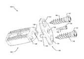
- FIGS. 5 and 6are exploded views of the implant of FIG. 1 .
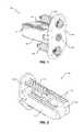
- FIG. 7is side view looking into a distal end of the implant of FIG. 1 .
- FIG. 8is a cross-sectional view of the implant looking into a plane A of FIG. 7 .
- FIG. 9is a perspective view of another exemplary implant according to the principles of the present disclosure.
- FIG. 10is an isometric view of the implant of FIG. 9 looking in an opposite direction of FIG. 9 .
- FIGS. 11-12illustrate an attachment member of the exemplary implant according to the principles of the present disclosure.
- FIG. 13illustrates a bottom view of the attachment member.
- FIG. 14is a cross-sectional view of the attachment member in plane B of FIG. 13 .
- proximal and distalare applied herein to denote specific ends of components of the instrument described herein.
- a proximal endrefers to the end of an instrument nearer to an operator of the instrument when the instrument is being used.
- a distal endrefers to the end of a component further from the operator and extending towards the surgical area of a patient and/or the implant.
- an exemplary implant 100comprises a spacer 102 , a plate 104 , one or more temporary fixation screws 106 , and an attachment member 108 .
- the spacer 102may be configured for insertion through a lateral or anterior aspect of the spine and into a disc space between two adjacent vertebrae.
- the spacer 102may include various recesses and apertures for receiving mating features of the plate 104 and the attachment member 108 .
- the fixation screws 106may be used to attach the plate 104 to the two adjacent vertebrae.
- the spacer 102may be inserted first into the patient through an opening in the side of the patient.
- LLIFlumbar lateral interbody fusion
- the patientmay be placed on his or her side while an opening is made from the side of the abdominal region to the spine.
- the spacer 102may be compressed between the vertebrae providing some amount of force to restrain movement of the spacer 102 .
- fixation structuressuch as rods, screws, and plates.
- the patientIn order to insert the fixation structures, the patient must be rotated from his or her side to the belly or the back side.
- the spacer 102could become dislodged and migrate posteriorly towards the patient's spinal cord or anteriorly towards the patient's vascular structures. Accordingly, the plate 104 may be attached to the spacer 102 and adjacent vertebrae using the temporary fixation screws 106 and attachment member 108 .
- the spacer 102may be formed by a sidewall that includes an anterior wall 118 and a posterior wall 120 which are coupled by a proximal side wall 122 and a distal side wall 124 .
- a middle wall 126may extend from the anterior wall 118 to the posterior wall 120 to provide additional reinforcement of the spacer 102 at a location about halfway between the proximal and distal side walls 118 and 120 .
- the spacer 102includes a superior surface 110 and an inferior surface 112 for engagement with the adjacent vertebrae. Both surfaces 110 and 112 may include teeth 114 or ridges to resist migration of the implant 100 laterally.
- a bullet-nose 116may ease insertion of the spacer 102 into the disc space.
- the spacer 102further includes recessed portions 128 extending partially through portions of the proximal side wall 122 and into the anterior wall 118 and posterior wall 120 .
- the recessed portions 128may include a profile configured to receive projections of an insertion instrument or a pair of projections 130 extending from the plate 104 .
- the proximal side wall 122also includes a first coupling aperture 132 configured to receive the attachment member 108 .
- the plate 104includes apertures 134 configured to receive the temporary fixation screws 106 .
- the apertures 134may include diameters that are less than a diameter of a head portion 107 of the screws 106 .
- the plate 104includes the projections 130 which extend away from the plate 104 in the distal direction to engage with the recessed portions 128 of the spacer 102 .
- the plate 104includes a second coupling aperture 136 configured to receive the attachment member 108 .
- the second coupling aperture 136includes a diameter less than a diameter of a head portion 109 of the attachment member 108 .
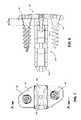
- the attachment member 108may include a thread 138 for engagement with a mating thread 140 of the spacer 102 .
- Prior threaded attachment members for plates and spacerstypically include screws with threads with a thread pitch TP typically less than a depth D of the threaded aperture in the spacer, sometimes by an order of at least three times and typically more on the order of six times such that at least six crests of the thread engage the spacer.
- the thread pitchis at most D/3 or more typically quite less and on the order of approximately D/6.
- the thread 138 of the present attachment member 108may include a thread pitch TP that is significantly greater than prior thread pitches.
- the thread 138may include a TP that is greater than one third of depth D of the first coupling aperture 132 in the proximal wall 122 of the spacer 102 .
- the thread 138permits secure coupling of the spacer 102 with the plate 104 by one half rotation of the attachment member 108 to engage less than one full crest of the thread 138 .
- the thread 138includes a long lead (pitch) trapezoidal form thread as seen in the cross-sectional view of FIG. 14 .
- the thread 138includes a modified Acme thread.
- the threadincludes a first thread 138 a and a second thread 138 b with two separate leads forming a dual lead dual thread.
- the thread 138includes a double lead and a substantially steep thread pitch greater than or equal to approximately two times D where D is a depth of the first coupling aperture 132 (or a thickness of the proximal wall 122 ) of the spacer 102 .
- the thread 138permits secure coupling of the spacer 102 with the plate 104 by 180 degrees of rotation of the attachment member 108 .
- FIGS. 9-10illustrate another exemplary implant 200 including the same or similar features as the first implant 100 . However, in implant 200 a single temporary fixation screw 106 is provided. Otherwise, the same features are present as described above with reference to implant 100 .
Landscapes
- Health & Medical Sciences (AREA)
- Orthopedic Medicine & Surgery (AREA)
- Engineering & Computer Science (AREA)
- Biomedical Technology (AREA)
- Neurology (AREA)
- Life Sciences & Earth Sciences (AREA)
- General Health & Medical Sciences (AREA)
- Heart & Thoracic Surgery (AREA)
- Veterinary Medicine (AREA)
- Public Health (AREA)
- Animal Behavior & Ethology (AREA)
- Surgery (AREA)
- Cardiology (AREA)
- Oral & Maxillofacial Surgery (AREA)
- Transplantation (AREA)
- Vascular Medicine (AREA)
- Molecular Biology (AREA)
- Medical Informatics (AREA)
- Nuclear Medicine, Radiotherapy & Molecular Imaging (AREA)
- Prostheses (AREA)
- Surgical Instruments (AREA)
Abstract
Description
Claims (9)
Priority Applications (6)
| Application Number | Priority Date | Filing Date | Title |
|---|---|---|---|
| US14/634,107US9603718B2 (en) | 2014-02-27 | 2015-02-27 | Spacer with temporary fixation plate |
| EP16156169.1AEP3058898B1 (en) | 2015-02-17 | 2016-02-17 | Spacer with temporary fixation plate |
| CN201680000323.8ACN106068110A (en) | 2015-02-17 | 2016-02-17 | There is the pad of interim fixed plate |
| PCT/IB2016/000148WO2016132209A1 (en) | 2015-02-17 | 2016-02-17 | Spacer with temporary fixation plate |
| BR112017000601ABR112017000601A2 (en) | 2015-02-17 | 2016-02-17 | spacer with temporary mounting plate. |
| US15/283,760US9763805B2 (en) | 2014-02-27 | 2016-10-03 | Spacer with temporary fixation plate |
Applications Claiming Priority (3)
| Application Number | Priority Date | Filing Date | Title |
|---|---|---|---|
| US201461945314P | 2014-02-27 | 2014-02-27 | |
| US201562117384P | 2015-02-17 | 2015-02-17 | |
| US14/634,107US9603718B2 (en) | 2014-02-27 | 2015-02-27 | Spacer with temporary fixation plate |
Related Child Applications (1)
| Application Number | Title | Priority Date | Filing Date |
|---|---|---|---|
| US15/283,760DivisionUS9763805B2 (en) | 2014-02-27 | 2016-10-03 | Spacer with temporary fixation plate |
Publications (2)
| Publication Number | Publication Date |
|---|---|
| US20160235546A1 US20160235546A1 (en) | 2016-08-18 |
| US9603718B2true US9603718B2 (en) | 2017-03-28 |
Family
ID=55450987
Family Applications (2)
| Application Number | Title | Priority Date | Filing Date |
|---|---|---|---|
| US14/634,107ActiveUS9603718B2 (en) | 2014-02-27 | 2015-02-27 | Spacer with temporary fixation plate |
| US15/283,760ActiveUS9763805B2 (en) | 2014-02-27 | 2016-10-03 | Spacer with temporary fixation plate |
Family Applications After (1)
| Application Number | Title | Priority Date | Filing Date |
|---|---|---|---|
| US15/283,760ActiveUS9763805B2 (en) | 2014-02-27 | 2016-10-03 | Spacer with temporary fixation plate |
Country Status (5)
| Country | Link |
|---|---|
| US (2) | US9603718B2 (en) |
| EP (1) | EP3058898B1 (en) |
| CN (1) | CN106068110A (en) |
| BR (1) | BR112017000601A2 (en) |
| WO (1) | WO2016132209A1 (en) |
Cited By (2)
| Publication number | Priority date | Publication date | Assignee | Title |
|---|---|---|---|---|
| US10952870B2 (en)* | 2016-07-26 | 2021-03-23 | Prism Surgical Designs Pty Ltd. | Spinal fixation and guidance system and method |
| US11026726B2 (en) | 2012-06-29 | 2021-06-08 | K2M, Inc. | Minimal-profile anterior cervical plate and cage apparatus and method of using same |
Families Citing this family (15)
| Publication number | Priority date | Publication date | Assignee | Title |
|---|---|---|---|---|
| US20150112444A1 (en)* | 2013-10-18 | 2015-04-23 | Camber Spine Technologies, LLC | Sacroiliac Joint Implants and Implantation Methods |
| US20200000595A1 (en) | 2016-06-07 | 2020-01-02 | HD LifeSciences LLC | High X-Ray Lucency Lattice Structures |
| CA3061043A1 (en) | 2017-02-14 | 2018-08-23 | HD LifeSciences LLC | High x-ray lucency lattice structures and variably x-ray lucent markers |
| CA3058365A1 (en) | 2017-04-01 | 2018-10-04 | HD LifeSciences LLC | Three-dimensional lattice structures for implants |
| EP3654875B1 (en)* | 2017-07-18 | 2024-08-28 | Blue Sky Technologies, LLC | Joint arthrodesis system |
| US10893953B2 (en)* | 2018-01-29 | 2021-01-19 | Seth Neubardt | Side pocket spinal fusion cage |
| US11147690B2 (en)* | 2018-02-28 | 2021-10-19 | Globus Medical Inc. | Systems and methods for performing spinal surgery |
| EP3826582A4 (en)* | 2018-07-26 | 2022-05-25 | Nanohive Medical LLC | DYNAMIC IMPLANT FIXATION PLATE |
| WO2020086914A1 (en)* | 2018-10-24 | 2020-04-30 | Life Spine, Inc. (A Delaware Corporation) | Facet wedge, wedge blocking plate and method of installation |
| US11497617B2 (en) | 2019-01-16 | 2022-11-15 | Nanohive Medical Llc | Variable depth implants |
| US11259936B2 (en) | 2020-06-15 | 2022-03-01 | Nofusco Corporation | Intravertebral implant system and methods of use |
| US11723778B1 (en) | 2021-09-23 | 2023-08-15 | Nofusco Corporation | Vertebral implant system and methods of use |
| US12144742B2 (en) | 2020-06-15 | 2024-11-19 | Foundation Surgical Group, Inc. | Implant system and methods of use |
| US11883300B2 (en) | 2020-06-15 | 2024-01-30 | Nofusco Corporation | Orthopedic implant system and methods of use |
| EP3970645B1 (en) | 2020-09-22 | 2025-06-11 | Biedermann Technologies GmbH & Co. KG | Implant, insertion device and plate assembly |
Citations (29)
| Publication number | Priority date | Publication date | Assignee | Title |
|---|---|---|---|---|
| US5928061A (en)* | 1996-10-21 | 1999-07-27 | Toyoda Koki Kabushiki Kaisha | Wheel-head feed mechanism and grinder using the same |
| US20040037915A1 (en)* | 2000-05-23 | 2004-02-26 | Jorg Dantlgraber | Drive device, in particular for the locking unit, the injection unit or the ejector of an injection-moulding machine for plastics |
| US20040053327A1 (en)* | 2000-07-25 | 2004-03-18 | Ralph Muller | Method and device for analysing chemical or biological samples |
| US20040210218A1 (en)* | 2001-10-15 | 2004-10-21 | Dixon Robert A. | Vertebral implant for bone fixation or interbody use |
| US20050141983A1 (en)* | 2002-11-29 | 2005-06-30 | Hiroshi Fujii | Multi-pitch screw, multi-pitch nut, feed screw device using the screw and nut, and method of producing the nut |
| US20090210064A1 (en)* | 2003-02-06 | 2009-08-20 | Beat Lechmann | Intervertebral implant |
| US7887595B1 (en)* | 2005-12-05 | 2011-02-15 | Nuvasive, Inc. | Methods and apparatus for spinal fusion |
| US20110190892A1 (en)* | 2010-02-01 | 2011-08-04 | X-Spine Systems, Inc. | Spinal implant co-insertion system and method |
| US20130060337A1 (en)* | 2011-09-06 | 2013-03-07 | Samuel Petersheim | Spinal Plate |
| US20130178872A1 (en)* | 2012-01-11 | 2013-07-11 | Edgar Louis Shriver | Intravascular suturing device for simultaneously placing 3-7 sutures with ideal spacing to close large openings in vessels including calfified |
| US20130238095A1 (en)* | 2012-03-06 | 2013-09-12 | Nicholas Pavento | Nubbed Plate |
| US20130345813A1 (en)* | 2012-06-22 | 2013-12-26 | Sheryl Frank | Dual Anchor Lateral Vertebral Body Fixation Plates |
| US20140012380A1 (en)* | 2012-06-29 | 2014-01-09 | DuPuy Synthes Products, LLC | Lateral insertion spinal implant |
| US20140046447A1 (en)* | 2011-07-12 | 2014-02-13 | Spinesmith Partners, L.P. | Cervical implant with exterior face plate |
| US20140277471A1 (en)* | 2013-03-15 | 2014-09-18 | Jason Gray | Expandable Intervertebral Implant |
| US20140277497A1 (en)* | 2013-03-15 | 2014-09-18 | Globus Medical, Inc. | Interbody Standalone Intervertebral Implant |
| US20150005879A1 (en)* | 2013-06-28 | 2015-01-01 | Bacem Georges | Spinal Alignment Clip |
| US20150025635A1 (en)* | 2013-07-17 | 2015-01-22 | Aesculap Implant Systems, Llc | Spinal interbody device, system and method |
| US20150057754A1 (en)* | 2013-08-22 | 2015-02-26 | Globus Medical, Inc. | Interbody Fusion Devices with Self-Affixing Mechanisms |
| US20150238327A1 (en)* | 2014-02-27 | 2015-08-27 | Alphatec Spine, Inc. | Spinal Implants and Insertion Instruments |
| US20150328005A1 (en)* | 2014-05-15 | 2015-11-19 | Globus Medical, Inc | Standalone Interbody Implants |
| US20150328010A1 (en)* | 2014-05-15 | 2015-11-19 | Globus Medical, Inc. | Standalone interbody implants |
| US20150328009A1 (en)* | 2014-05-15 | 2015-11-19 | Globus Medical, Inc. | Standalone Interbody Implants |
| US20150328007A1 (en)* | 2014-05-15 | 2015-11-19 | Globus Medical, Inc | Standalone Interbody Implants |
| US20160007983A1 (en)* | 2008-05-07 | 2016-01-14 | George Frey | Configurable Intervertebral Implant |
| US20160015523A1 (en)* | 2014-07-16 | 2016-01-21 | Amedica Corporation | Intervertebral spacers and related methods and instruments |
| US20160045326A1 (en)* | 2014-08-18 | 2016-02-18 | Eric Hansen | Interbody spacer system |
| US20160058480A1 (en)* | 2014-09-03 | 2016-03-03 | Aesculap Implant Systems, Llc | Fastener, spinal interbody system including same and method |
| US20160067053A1 (en)* | 2014-05-07 | 2016-03-10 | Perumala Corporation | Enhanced Artificial Disk |
Family Cites Families (10)
| Publication number | Priority date | Publication date | Assignee | Title |
|---|---|---|---|---|
| JPH066810Y2 (en)* | 1989-11-29 | 1994-02-23 | 旭光学工業株式会社 | Vertebral body fixation plate |
| US7094239B1 (en)* | 1999-05-05 | 2006-08-22 | Sdgi Holdings, Inc. | Screws of cortical bone and method of manufacture thereof |
| US6984234B2 (en)* | 2003-04-21 | 2006-01-10 | Rsb Spine Llc | Bone plate stabilization system and method for its use |
| US8216312B2 (en)* | 2007-05-31 | 2012-07-10 | Zimmer Spine, Inc. | Spinal interbody system and method |
| US8092505B2 (en)* | 2008-01-28 | 2012-01-10 | Acumed Llc | Bone nail |
| US8328872B2 (en)* | 2008-09-02 | 2012-12-11 | Globus Medical, Inc. | Intervertebral fusion implant |
| AU2012332447A1 (en)* | 2011-11-01 | 2014-05-15 | Amedica Corporation | Implants with a connectable insert and related systems and methods |
| US9186257B2 (en)* | 2012-10-11 | 2015-11-17 | Rhausler, Inc. | Bone plate and fusion cage interface |
| US10864081B2 (en)* | 2012-10-19 | 2020-12-15 | Tyber Medical, LLC | Wedge osteotomy device and method of use |
| US20160151171A1 (en)* | 2013-07-17 | 2016-06-02 | Spinal Usa, Inc. | Modular intervertebral cage system |
- 2015
- 2015-02-27USUS14/634,107patent/US9603718B2/enactiveActive
- 2016
- 2016-02-17EPEP16156169.1Apatent/EP3058898B1/enactiveActive
- 2016-02-17BRBR112017000601Apatent/BR112017000601A2/ennot_activeApplication Discontinuation
- 2016-02-17WOPCT/IB2016/000148patent/WO2016132209A1/ennot_activeCeased
- 2016-02-17CNCN201680000323.8Apatent/CN106068110A/enactivePending
- 2016-10-03USUS15/283,760patent/US9763805B2/enactiveActive
Patent Citations (29)
| Publication number | Priority date | Publication date | Assignee | Title |
|---|---|---|---|---|
| US5928061A (en)* | 1996-10-21 | 1999-07-27 | Toyoda Koki Kabushiki Kaisha | Wheel-head feed mechanism and grinder using the same |
| US20040037915A1 (en)* | 2000-05-23 | 2004-02-26 | Jorg Dantlgraber | Drive device, in particular for the locking unit, the injection unit or the ejector of an injection-moulding machine for plastics |
| US20040053327A1 (en)* | 2000-07-25 | 2004-03-18 | Ralph Muller | Method and device for analysing chemical or biological samples |
| US20040210218A1 (en)* | 2001-10-15 | 2004-10-21 | Dixon Robert A. | Vertebral implant for bone fixation or interbody use |
| US20050141983A1 (en)* | 2002-11-29 | 2005-06-30 | Hiroshi Fujii | Multi-pitch screw, multi-pitch nut, feed screw device using the screw and nut, and method of producing the nut |
| US20090210064A1 (en)* | 2003-02-06 | 2009-08-20 | Beat Lechmann | Intervertebral implant |
| US7887595B1 (en)* | 2005-12-05 | 2011-02-15 | Nuvasive, Inc. | Methods and apparatus for spinal fusion |
| US20160007983A1 (en)* | 2008-05-07 | 2016-01-14 | George Frey | Configurable Intervertebral Implant |
| US20110190892A1 (en)* | 2010-02-01 | 2011-08-04 | X-Spine Systems, Inc. | Spinal implant co-insertion system and method |
| US20140046447A1 (en)* | 2011-07-12 | 2014-02-13 | Spinesmith Partners, L.P. | Cervical implant with exterior face plate |
| US20130060337A1 (en)* | 2011-09-06 | 2013-03-07 | Samuel Petersheim | Spinal Plate |
| US20130178872A1 (en)* | 2012-01-11 | 2013-07-11 | Edgar Louis Shriver | Intravascular suturing device for simultaneously placing 3-7 sutures with ideal spacing to close large openings in vessels including calfified |
| US20130238095A1 (en)* | 2012-03-06 | 2013-09-12 | Nicholas Pavento | Nubbed Plate |
| US20130345813A1 (en)* | 2012-06-22 | 2013-12-26 | Sheryl Frank | Dual Anchor Lateral Vertebral Body Fixation Plates |
| US20140012380A1 (en)* | 2012-06-29 | 2014-01-09 | DuPuy Synthes Products, LLC | Lateral insertion spinal implant |
| US20140277471A1 (en)* | 2013-03-15 | 2014-09-18 | Jason Gray | Expandable Intervertebral Implant |
| US20140277497A1 (en)* | 2013-03-15 | 2014-09-18 | Globus Medical, Inc. | Interbody Standalone Intervertebral Implant |
| US20150005879A1 (en)* | 2013-06-28 | 2015-01-01 | Bacem Georges | Spinal Alignment Clip |
| US20150025635A1 (en)* | 2013-07-17 | 2015-01-22 | Aesculap Implant Systems, Llc | Spinal interbody device, system and method |
| US20150057754A1 (en)* | 2013-08-22 | 2015-02-26 | Globus Medical, Inc. | Interbody Fusion Devices with Self-Affixing Mechanisms |
| US20150238327A1 (en)* | 2014-02-27 | 2015-08-27 | Alphatec Spine, Inc. | Spinal Implants and Insertion Instruments |
| US20160067053A1 (en)* | 2014-05-07 | 2016-03-10 | Perumala Corporation | Enhanced Artificial Disk |
| US20150328009A1 (en)* | 2014-05-15 | 2015-11-19 | Globus Medical, Inc. | Standalone Interbody Implants |
| US20150328007A1 (en)* | 2014-05-15 | 2015-11-19 | Globus Medical, Inc | Standalone Interbody Implants |
| US20150328010A1 (en)* | 2014-05-15 | 2015-11-19 | Globus Medical, Inc. | Standalone interbody implants |
| US20150328005A1 (en)* | 2014-05-15 | 2015-11-19 | Globus Medical, Inc | Standalone Interbody Implants |
| US20160015523A1 (en)* | 2014-07-16 | 2016-01-21 | Amedica Corporation | Intervertebral spacers and related methods and instruments |
| US20160045326A1 (en)* | 2014-08-18 | 2016-02-18 | Eric Hansen | Interbody spacer system |
| US20160058480A1 (en)* | 2014-09-03 | 2016-03-03 | Aesculap Implant Systems, Llc | Fastener, spinal interbody system including same and method |
Cited By (2)
| Publication number | Priority date | Publication date | Assignee | Title |
|---|---|---|---|---|
| US11026726B2 (en) | 2012-06-29 | 2021-06-08 | K2M, Inc. | Minimal-profile anterior cervical plate and cage apparatus and method of using same |
| US10952870B2 (en)* | 2016-07-26 | 2021-03-23 | Prism Surgical Designs Pty Ltd. | Spinal fixation and guidance system and method |
Also Published As
| Publication number | Publication date |
|---|---|
| EP3058898A1 (en) | 2016-08-24 |
| US20160235546A1 (en) | 2016-08-18 |
| WO2016132209A1 (en) | 2016-08-25 |
| BR112017000601A2 (en) | 2018-07-17 |
| CN106068110A (en) | 2016-11-02 |
| EP3058898B1 (en) | 2023-05-10 |
| US20170020680A1 (en) | 2017-01-26 |
| US9763805B2 (en) | 2017-09-19 |
Similar Documents
| Publication | Publication Date | Title |
|---|---|---|
| US9603718B2 (en) | Spacer with temporary fixation plate | |
| US11890035B2 (en) | Articulating rod assembly | |
| US9421112B2 (en) | Fixation system for spinal cages | |
| EP2555715B1 (en) | Intervertebral implant | |
| US7967847B2 (en) | Spinal stabilization and reconstruction with fusion rods | |
| US8246657B1 (en) | Spinal cross connector | |
| US7922746B2 (en) | Spinal rod extenders and methods of use | |
| US10687861B2 (en) | Systems and methods for spinal compression, distraction, and fixation | |
| US8147521B1 (en) | Systems and methods for treating spinal deformities | |
| US8414623B2 (en) | Connector for connecting elongated members | |
| CN108498150A (en) | spinal implant system and method | |
| US20130090688A1 (en) | Posterior vertebral plating system | |
| US8147529B2 (en) | Anterior cervical instrumentation systems, methods and devices | |
| US20120221056A1 (en) | Apparatus for linking implants and reducing deformities | |
| CN111479527B (en) | Spinal implant system and method of use | |
| US12042183B2 (en) | Integral double rod spinal construct | |
| US20170105766A1 (en) | Polyaxial Bone Screw and Bushing | |
| US9795413B2 (en) | Spinal fixation member | |
| US20120245693A1 (en) | Spinal fixation device | |
| JP6677633B2 (en) | Spinal fusion system | |
| EP3419536B1 (en) | Integral double rod spinal construct |
Legal Events
| Date | Code | Title | Description |
|---|---|---|---|
| AS | Assignment | Owner name:ALPHATEC SPINE, INC., CALIFORNIA Free format text:ASSIGNMENT OF ASSIGNORS INTEREST;ASSIGNORS:CHENG, YANG;COSTABILE, JONATHON T.;REEL/FRAME:035724/0561 Effective date:20150526 | |
| AS | Assignment | Owner name:GLOBUS MEDICAL, INC., PENNSYLVANIA Free format text:INTELLECTUAL PROPERTY SECURITY AGREEMENT;ASSIGNORS:ALPHATEC HOLDINGS, INC.;ALPHATEC SPINE, INC.;REEL/FRAME:040108/0202 Effective date:20160901 | |
| STCF | Information on status: patent grant | Free format text:PATENTED CASE | |
| AS | Assignment | Owner name:ALPHATEC HOLDINGS, INC., CALIFORNIA Free format text:RELEASE BY SECURED PARTY;ASSIGNOR:GLOBUS MEDICAL, INC.;REEL/FRAME:047485/0084 Effective date:20181107 Owner name:ALPHATEC SPINE, INC., CALIFORNIA Free format text:RELEASE BY SECURED PARTY;ASSIGNOR:GLOBUS MEDICAL, INC.;REEL/FRAME:047485/0084 Effective date:20181107 | |
| AS | Assignment | Owner name:SQUADRON MEDICAL FINANCE SOLUTIONS LLC, CONNECTICUT Free format text:SECURITY INTEREST;ASSIGNORS:ALPHATEC HOLDINGS, INC.;ALPHATEC SPINE, INC.;REEL/FRAME:047494/0562 Effective date:20181106 Owner name:SQUADRON MEDICAL FINANCE SOLUTIONS LLC, CONNECTICU Free format text:SECURITY INTEREST;ASSIGNORS:ALPHATEC HOLDINGS, INC.;ALPHATEC SPINE, INC.;REEL/FRAME:047494/0562 Effective date:20181106 | |
| MAFP | Maintenance fee payment | Free format text:PAYMENT OF MAINTENANCE FEE, 4TH YR, SMALL ENTITY (ORIGINAL EVENT CODE: M2551); ENTITY STATUS OF PATENT OWNER: SMALL ENTITY Year of fee payment:4 | |
| AS | Assignment | Owner name:ALPHATEC HOLDINGS, INC., CALIFORNIA Free format text:RELEASE OF SECURITY INTEREST IN PATENT COLLATERAL AT REEL/FRAME NO. 47494/0562;ASSIGNOR:SQUADRON MEDICAL FINANCE SOLUTIONS LLC;REEL/FRAME:057177/0687 Effective date:20210804 Owner name:ALPHATEC SPINE, INC., CALIFORNIA Free format text:RELEASE OF SECURITY INTEREST IN PATENT COLLATERAL AT REEL/FRAME NO. 47494/0562;ASSIGNOR:SQUADRON MEDICAL FINANCE SOLUTIONS LLC;REEL/FRAME:057177/0687 Effective date:20210804 | |
| FEPP | Fee payment procedure | Free format text:ENTITY STATUS SET TO UNDISCOUNTED (ORIGINAL EVENT CODE: BIG.); ENTITY STATUS OF PATENT OWNER: LARGE ENTITY | |
| AS | Assignment | Owner name:MIDCAP FUNDING IV TRUST, MARYLAND Free format text:SECURITY INTEREST;ASSIGNORS:ALPHATEC SPINE, INC.;SAFEOP SURGICAL, INC.;REEL/FRAME:062310/0001 Effective date:20230106 | |
| AS | Assignment | Owner name:WILMINGTON TRUST, NATIONAL ASSOCIATION, DELAWARE Free format text:SECURITY INTEREST;ASSIGNORS:ALPHATEC SPINE, INC.;SAFEOP SURGICAL, INC.;REEL/FRAME:062681/0020 Effective date:20230106 | |
| MAFP | Maintenance fee payment | Free format text:PAYMENT OF MAINTENANCE FEE, 8TH YEAR, LARGE ENTITY (ORIGINAL EVENT CODE: M1552); ENTITY STATUS OF PATENT OWNER: LARGE ENTITY Year of fee payment:8 |