US9603641B2 - Device for osteosynthesis - Google Patents
Device for osteosynthesisDownload PDFInfo
- Publication number
- US9603641B2 US9603641B2US14/807,363US201514807363AUS9603641B2US 9603641 B2US9603641 B2US 9603641B2US 201514807363 AUS201514807363 AUS 201514807363AUS 9603641 B2US9603641 B2US 9603641B2
- Authority
- US
- United States
- Prior art keywords
- opening
- engaging
- central axis
- bone
- proximal
- Prior art date
- Legal status (The legal status is an assumption and is not a legal conclusion. Google has not performed a legal analysis and makes no representation as to the accuracy of the status listed.)
- Active
Links
Images


Classifications
- A—HUMAN NECESSITIES
- A61—MEDICAL OR VETERINARY SCIENCE; HYGIENE
- A61B—DIAGNOSIS; SURGERY; IDENTIFICATION
- A61B17/00—Surgical instruments, devices or methods
- A61B17/56—Surgical instruments or methods for treatment of bones or joints; Devices specially adapted therefor
- A61B17/58—Surgical instruments or methods for treatment of bones or joints; Devices specially adapted therefor for osteosynthesis, e.g. bone plates, screws or setting implements
- A61B17/68—Internal fixation devices, including fasteners and spinal fixators, even if a part thereof projects from the skin
- A61B17/80—Cortical plates, i.e. bone plates; Instruments for holding or positioning cortical plates, or for compressing bones attached to cortical plates
- A61B17/8052—Cortical plates, i.e. bone plates; Instruments for holding or positioning cortical plates, or for compressing bones attached to cortical plates immobilised relative to screws by interlocking form of the heads and plate holes, e.g. conical or threaded
- A61B17/8057—Cortical plates, i.e. bone plates; Instruments for holding or positioning cortical plates, or for compressing bones attached to cortical plates immobilised relative to screws by interlocking form of the heads and plate holes, e.g. conical or threaded the interlocking form comprising a thread
- A—HUMAN NECESSITIES
- A61—MEDICAL OR VETERINARY SCIENCE; HYGIENE
- A61B—DIAGNOSIS; SURGERY; IDENTIFICATION
- A61B17/00—Surgical instruments, devices or methods
- A61B17/56—Surgical instruments or methods for treatment of bones or joints; Devices specially adapted therefor
- A61B17/58—Surgical instruments or methods for treatment of bones or joints; Devices specially adapted therefor for osteosynthesis, e.g. bone plates, screws or setting implements
- A61B17/68—Internal fixation devices, including fasteners and spinal fixators, even if a part thereof projects from the skin
- A61B17/82—Internal fixation devices, including fasteners and spinal fixators, even if a part thereof projects from the skin for bone cerclage
- A—HUMAN NECESSITIES
- A61—MEDICAL OR VETERINARY SCIENCE; HYGIENE
- A61B—DIAGNOSIS; SURGERY; IDENTIFICATION
- A61B17/00—Surgical instruments, devices or methods
- A61B17/56—Surgical instruments or methods for treatment of bones or joints; Devices specially adapted therefor
- A61B17/58—Surgical instruments or methods for treatment of bones or joints; Devices specially adapted therefor for osteosynthesis, e.g. bone plates, screws or setting implements
- A61B17/68—Internal fixation devices, including fasteners and spinal fixators, even if a part thereof projects from the skin
- A61B17/84—Fasteners therefor or fasteners being internal fixation devices
- A61B17/86—Pins or screws or threaded wires; nuts therefor
- A—HUMAN NECESSITIES
- A61—MEDICAL OR VETERINARY SCIENCE; HYGIENE
- A61B—DIAGNOSIS; SURGERY; IDENTIFICATION
- A61B17/00—Surgical instruments, devices or methods
- A61B17/04—Surgical instruments, devices or methods for suturing wounds; Holders or packages for needles or suture materials
- A61B17/0401—Suture anchors, buttons or pledgets, i.e. means for attaching sutures to bone, cartilage or soft tissue; Instruments for applying or removing suture anchors
- A61B2017/042—Suture anchors, buttons or pledgets, i.e. means for attaching sutures to bone, cartilage or soft tissue; Instruments for applying or removing suture anchors plastically deformed during insertion
- A61B2017/0422—Suture anchors, buttons or pledgets, i.e. means for attaching sutures to bone, cartilage or soft tissue; Instruments for applying or removing suture anchors plastically deformed during insertion by insertion of a separate member into the body of the anchor
- A61B2017/0425—Suture anchors, buttons or pledgets, i.e. means for attaching sutures to bone, cartilage or soft tissue; Instruments for applying or removing suture anchors plastically deformed during insertion by insertion of a separate member into the body of the anchor the anchor or the separate member comprising threads, e.g. a set screw in the anchor
Definitions
- the present inventiongenerally relates to a device for osteosynthesis and, in particular, to a bone plate for stabilization of bones.
- fixation of osteosynthetic devices to bonesis usually effected by means of anchoring elements such as screws and pins. It is sometimes desirable to allow the fixation of the anchoring elements to the osteosynthetic device and the bone at an angle chosen by the surgeon.
- a device for osteosynthesis for an angularly stable connection of an anchoring element in a bone plateis known from German Patent No. DE 10 2005 042 766 to Orschler.
- This known devicehas the disadvantage that the fixation of an anchoring element and a bone plate is achievable only due to the interaction between a bone screw head with a plate bore.
- increasing forces and loads applied to the bone platemay result in a loosening of the fixation of the bone screw in the plate bore.
- the present inventionrelates to a device for osteosynthesis allowing an angularly stable connection of an anchoring element (e.g., a bone screw) to an osteosynthetic device (e.g., a bone plate) as well as a rigid locking of the anchoring element in the osteosynthetic device.
- an anchoring elemente.g., a bone screw
- an osteosynthetic devicee.g., a bone plate
- the present inventionrelates to a device for osteosynthesis comprising a body having a proximal surface, a distal surface configured and dimensioned to face a target portion of bone over which the body is to be mounted and a through opening extending through the body from the proximal surface to the distal surface along a central axis, the through hole including a first protrusion extending from an inner surface thereof toward the central axis, the first protrusion being biased toward an unstressed state in which the first protrusion extends into the through opening to a first distance from the central axis, the first protrusion being movable toward the inner surface when subjected to a force directed outward from the central axis.
- the present inventionalso relates to a device for osteosynthesis, which comprises a proximal surface, a distal surface configured to face a bone in an operative configuration, and a through opening for receiving an anchoring element connecting the proximal and distal surfaces.
- the through openinghas a central axis, an inner surface and a number, N, of protrusions extending therethrough in a direction of the central axis, wherein the protrusions are movable and/or deformable in a direction from the central axis towards the inner surface of the through opening so that the through opening is radially expandable.
- the through openingis radially expandable by at least 2% of the diameter of the through opening.
- the protrusionscomprise front faces facing the central axis wherein the movability/deformability of the protrusions is not based on the deformability of the front faces.
- the protrusions and the inner surface of the through openingare formed as a unitary element.
- the protrusionsare elastically deformable. This configuration increases the stability of a bone fixation procedure due to a non-positive connection between the osteosynthetic device and a bone fixation element inserted therethrough, as will be described in greater detail later on.
- a first one of the protrusionscomprises a front face facing the central axis, a circumference of the front face being less than 360°, preferably 190° to 220°.
- the protrusionsnumber between 3 and 6.
- the front faces of the protrusionsare circumferentially separated from each other along an inner surface of the through opening.
- the through openinghas a non-circular cross-section.
- front faces of each of the protrusionshave a different surface area f(N).
- front faces of each of the protrusionshave an identical surface area f(N).
- an inner surface of the through opening without the areas f(N)has a total area F, and wherein the ratio f(N)/F is in the range of 2 to 15%.
- the ratio f(N)/Fis between 20% and 50%.
- the surfaces of the front faces of the protrusionscomprise a three-dimensional structure, preferably a macro-structure.
- the front faces of the protrusionsare provided with a thread or a thread-like structure.
- the front facesare provided with lips.
- the front faces of the protrusions facing the central axisform a virtual body having an essentially circular cross-section when measured orthogonal to the central axis.
- the front faces of the protrusionsform a virtual body; the virtual body is conical, preferably with a cone angle in the range of 5° to 15° to permit a non-positive connection with a conical screw head.
- the virtual body formed by the front faces of the protrusions facing the central axishas a form of a spherical segment, preferably of a hemisphere. This configuration allows the advantage of a non-positive connection with a spherical screw head.
- the virtual body formed by the front faces of the protrusionsis a cylinder. This configuration allows the advantage of a non-positive connection with a conical screw head.
- the protrusionsare connected to the inner surface by a connecting part; the connecting part is longitudinally aligned with one of the distal surface of the device and the proximal surface of the device.
- the connecting partmay be positioned to be equidistant from the proximal and distal surfaces.
- the front facesare arranged non-parallel to the central axis of the through opening.
- the front facesare arranged parallel to the central axis of the through opening.
- back sides of the protrusionsare provided with wedge-shaped male elements and the inner surface of the through opening is provided with corresponding cavities.
- a bone fixation assemblyis provided with at least one anchoring element insertable in the through opening.
- FIG. 1illustrates a perspective view of a cross-section of an exemplary embodiment of the device according to the present invention
- FIG. 2illustrates a perspective view of another exemplary embodiment of the device according to the present invention
- FIG. 3illustrates a perspective view of a further exemplary embodiment of the device according to the present invention
- FIG. 4illustrates a partial perspective view of a further exemplary embodiment of the through opening of a device according to the present invention.
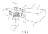
- FIG. 5illustrates a perspective view of a bone fixation assembly comprising the device for osteosynthesis and the anchoring element insertable in the through opening of the device.
- the present inventionrelates to a system and method for the fixation of an osteosynthetic device to a bone via a bone fixation device (e.g., a bone screw) in a manner ensuring that there is no loss of bony purchase over time after implantation.
- a bone fixation devicee.g., a bone screw
- An exemplary bone plate according to the present inventioncomprises a through opening extending therethrough and having a central opening axis.
- the through openingdefines a channel extending therethrough and comprises a first protrusion extending from an inner wall thereof a predetermined distance radially into the channel.
- the first protrusionis provided with an elastically deformable hinge coupled to the inner surface of the through opening.
- the first protrusionis provided with accordioned layers, as will be described in greater detail later on, to aid in radial expansion of the channel.
- the protrusionis configured so that, when subject to a predetermined force (e.g., by a bone fixation screw inserted into the channel), individual layers of the accordioned protrusion radially compress against one another to increase a diameter of the channel and permit the locking insertion of the bone fixation screw into the bone.
- the exemplary bone plate according to the present inventionpermits the insertion of a range of bone fixation screws the outer diameters of whose shafts and heads fall within predetermined ranges.
- FIG. 1illustrates a cross-section of a device 1 according to a first embodiment of the present invention.
- the device 1is a bone fixation plate having a proximal surface 8 , a distal surface 9 configured and dimensioned for facing a bone in an operative configuration and a through opening 2 connecting the proximal surface 8 and the distal surface 9 .
- a cross-section of the through opening 2is substantially clover-shaped and comprises four radial recesses 7 having a first radius of curvature and separated from one another by a plurality of protrusions 5 formed on a portion of the opening having a second radius of curvature, the second radius of curvature being greater than the first radius of curvature, as shown in FIG. 1 . That is, the cross-section of the through opening 2 has a form of a tetragon, wherein the angles of the tetragon are extended by the circular radial recesses 7 .
- the through opening 2has an inner surface 4 and a central axis 3 .
- the protrusions 5extend from the inner surface 4 of the through opening 2 in the direction of the central axis 3 by a predetermined distance. Specifically, as will be described in greater detail hereinafter, the protrusions 5 are first provided in a biased configuration wherein the protrusions extend into a channel 10 defined by the through opening 2 by a first predetermined distance. Compression of the protrusions 5 causes a reduction of the first predetermined distance to a second smaller distance suitable to permit lockable insertion of a bone fixation device through the channel 10 .
- Each of the protrusions 5extends radially into the channel 10 from an inner wall portion 13 having the second radius of curvature as described above.
- First, second, third and fourth walls 14 , 15 , 16 and 17extend out from the inner wall portion 13 in a direction toward the central axis 3 .
- a width of each of the first, second, third and fourth walls 14 , 15 , 16 , 17is sequentially reduced in a direction approaching the central axis to prevent adjacent ones of the protrusions 5 from contacting one another as they approach a reduced diameter portion of the channel 10 toward the central axis 3 , as those skilled in the art will understand.
- a curvature of each of the first, second, third and fourth walls 14 , 15 , 16 , 17is substantially similar to a curvature of the inner wall portion 13 .
- the first wall 14extends out from the inner wall 13 at an angle substantially perpendicular to the central axis 3 by a first predetermined distance.
- a distal face of the first wall 14is aligned with the distal surface 9 of the device 1 , the first wall 14 having a longitudinal length smaller than a longitudinal length of the inner wall portion 13 .
- a second wall 15extends from an end of the first wall 14 , the second wall 15 extending substantially parallel to the central axis 3 in a proximal direction, terminating at a proximal end of the inner wall portion 13 .
- a first groove 18is defined between the second wall 15 and the inner wall portion 13 , the first groove 18 allowing for radial compression of the protrusion 5 , as will be described in greater detail later on.
- the third wall 16extends away from an end of the second wall 15 in a direction also substantially perpendicular to the central axis 3 , the third wall 16 being substantially aligned with the proximal surface 8 .
- a length of the third wallis substantially similar to that of the first wall 14 .
- the fourth wall 17extends distally from an end of the third wall 16 , defining a second groove 19 between the fourth wall 17 and the second wall 15 .
- the fourth and second walls 17 , 15are movable/deformable into the first and second grooves 18 , 19 so that the through opening 2 is radially expandable.
- Each of the protrusions 5 shown in FIG. 1are formed as a single unit
- Front faces 6 of the fourth walls 17 of the protrusions 5 facing the central axis 3are provided with a three-dimensional macro-structure in the form of a thread. It is noted, however, that the front faces 6 may be provided with any other surface treatment or shape configured to conform to the outer wall of a head or shaft of a bone fixation device to be inserted therethrough. For example, the surface treatment may be selected to enhance a frictional engagement between the protrusion 5 and the bone fixation element (not shown).
- Each of the front faces 6has an area f(N). In the exemplary embodiment shown in FIG. 1 , the areas f(N) of each the protrusions 5 are identical to each other.
- the front faces 6 of the protrusions 5are arranged at a non-parallel angle relative to the central axis 3 and form a virtual body having a form of a cylindrical cone.
- a total area f(T) of all protrusions 5corresponds to the sum of the areas f(N), i.e.
- the device 1may first be positioned over a target portion of a bone being treated.
- the bone platemay be temporarily held in place (i.e., via a bone pin, etc.).
- a surgeon or other usermay then determine a required angle of insertion of a bone fixation device 1 through the through hole 2 .
- the insertion anglemay be selected to permit the bone fixation device to attach bone fragments to one another.
- the surgeonmay then insert the bone fixation device 11 into the through hole at the desired angle so that a longitudinal axis 11 ′ of the bone fixation device 11 is angled relative to the central axis 3 by an angle ⁇ .
- the width of the channel 10may be smaller than a width of a head of the bone fixation device 11 so that, as the head is advanced into the through hole 2 , at least a first one of the protrusions 5 is radially compressed.
- the selected angle of insertionwill determine which ones of the plurality of protrusions 5 are radially compressed, wherein those protrusions 5 lying in a plane of insertion of the bone fixation device (not shown) may undergo a greater degree of deflection than those separated from the plane of insertion.
- Each of the protrusions 5may therefore undergo varying degrees of radial compression, wherein some of the protrusions 5 may not undergo any compression at all.
- the exemplary protrusions 5 according to the present inventionpermit a polyaxial insertion of a bone fixation device through the through hole 2 at any desired angle which may be selected prior to or after positioning of the bone plate over the bone.
- FIG. 2illustrates a cross-section of a device 20 according to another embodiment of the present invention, wherein like elements have been referenced with the same reference number.
- the device 1 ′comprises the proximal surface 8 , distal surface 9 for facing a bone and a through opening 22 connecting the proximal surface 8 and the distal surface 9 .
- the through opening 22has the inner surface 4 and the central axis 3 .
- the through openingcomprises a plurality of protrusions 25 formed substantially similarly as the protrusions 5 of FIG. 1 .
- the protrusions 25are movable/deformable in the direction from the central axis 3 towards the inner surface 4 of the through opening 22 , so that the through opening 22 is radially expandable.
- a cross-section of the through opening 22 relative to the central axis 3has a substantially circular shape.
- Front faces 26 of the protrusions 25are arranged parallel to the central axis 3 and form a virtual body having the form of a circular cylinder.
- Areas f(N) of each of the protrusions 25are substantially identical to each other.
- the exemplary protrusions 25are formed of a separate unit selectively insertable into an opening 23 formed through the inner surface 4 of the through opening 22 .
- radially inner walls 12 of the protrusions 5are provided with wedge-shaped male elements 24 which may be locked in the respectively sized and shaped opening 23 .
- the openings 23may be longitudinally aligned with the distal surface 9 .
- the male elements 24may be bonded to the openings to prevent movement relative thereto.
- a proximal portion of the inner surface 4 of the through opening 2may comprise a female opening 14 formed as a pointed groove extending along the inner surface 4 and having a length substantially similar to a length of the radially inner wall 12 .
- the female opening 14may be sized and shaped to receive an abutment 13 extending along the radially inner wall 12 .
- the abutments 13do not contact the female openings 14 in a first operative configuration.
- the radially inner wall 12is formed with an angle extending substantially perpendicular to the central axis.
- the inner surface 4 of the through opening 2is formed with a conical taper so that a diameter of the through opening 2 decreases in a distal direction. Because of this configuration, when the male element 24 is fully seated within the opening 23 , a proximal portion of the protrusion including the abutment 13 does not contact the inner surface 4 or female opening 14 .
- Proximal faces 26 of the protrusions 25are formed with threading or another surface treatment configured to aid in frictional engagement with a bone fixation device and to aid in distal insertion thereof into a bone, as those skilled in the art will understand. As described in greater detail earlier, the front faces 26 may define a virtual conical shape of the channel 10 extending through the through hole 22 . It is noted that although the present embodiment is depicted with six protrusions 25 , any other number of protrusions may be employed without deviating from the spirit and scope of the present invention. For example, a surgeon may determine a required number of protrusions 25 depending on the requirement for a particular procedure and may add or remove protrusions 25 from the device 20 as needed prior to performing the procedure.
- An exemplary method according to the present embodimentis substantially similar to the method discussed above with respect to FIG. 1 .
- a bone fixation device(not shown) is inserted through the through hole 22 at a selected angle, insertion of the bone fixation device causing at least a portion of the protrusions 25 to deflect radially outward toward the inner surface 4 .
- the protrusions 25may deflect away from their biased positions by any distance up to a maximum deflection range wherein the abutments 13 come into contact with the female openings 14 .
- FIG. 3illustrates a cross-section of a device 30 according to another embodiment of the present invention, the device 30 having the proximal surface 8 , the distal surface 9 for facing a bone and a through opening 32 connecting the proximal surface 8 and the distal surface 9 .
- the through opening 32has the inner surface 4 and the central axis 3 .
- the through opening 32further comprises protrusions 35 extending from the inner surface 4 of the through opening 2 .
- the protrusions 35are movable/deformable in a direction from the central axis 3 towards the inner surface 4 of the through opening 32 so that the through opening 2 is radially expandable.
- a cross-sectional shape of the through opening 32is substantially circular and comprises a plurality of grooves 39 extending along its perimeter, as will be described in greater detail later on.
- Front faces 36 of the protrusions 35are arranged non-parallel to the central axis 3 and form a virtual body having a form of a circular cone, as described in greater detail in earlier embodiments.
- Each of the protrusions 36extends radially into the channel 10 from an inner wall 33 .
- the inner wall 33may be recessed into the inner surface 4 by a predetermined depth so as to create the grooves 39 .
- the recessed inner wall 33increases the depth by which the protrusions 35 may be deflected from their biased positions upon application of a force by a bone fixation device, thus providing for a greater degree of angulation of the bone fixation device through the through opening 32 .
- a tab 34extends out of the inner wall 33 at an equidistant position from the proximal and distal surfaces 8 , 9 .
- a width of the tab 34may be substantially equivalent to or smaller than a width of the inner wall 33 .
- the tab 34 and protrusion 35serve to define proximal and distal grooves 37 , 38 therebetween, the grooves 37 , 38 permitting deflection of the protrusion 35 thereinto upon application of a predetermined force by a bone fixation device.
- FIG. 4illustrates a cross-section of a device 40 according to another embodiment of the present invention.
- the device 40is formed substantially similarly as the device 1 of FIG. 1 but comprises only a single protrusion 45 .
- the device 40comprises a through opening 42 having inner surface 4 and central axis 3 .
- a cross-sectional shape of the through opening 42is substantially circular and is open to a substantially oval opening 43 located adjacent thereto.
- the protrusion 45extends through only the substantially circular through opening 42 and is movable/deformable in any direction from the central axis 3 towards the inner surface 4 .
- FIG. 4illustrates a cross-section of a device 40 according to another embodiment of the present invention.
- the device 40is formed substantially similarly as the device 1 of FIG. 1 but comprises only a single protrusion 45 .
- the device 40comprises a through opening 42 having inner surface 4 and central axis 3 .
- a cross-sectional shape of the through opening 42is substantially circular and is open to a substantially oval opening 43
- the protrusion 45comprises first, second, third and fourth walls 14 ′, 15 ′, 16 ′, 17 ′ permitting radial compression of the through opening 45 upon application of a predetermined minimum force from a bone fixation device.
- first wall 14 of FIG. 1was aligned with the distal surface 9
- first wall 14 ′ of the present embodimentis aligned with the proximal surface 8 .
- walls 14 , 15 , 16 , 17 of FIG. 1Subsequent walls 16 ′, 17 ′ and 18 ′ of the protrusion are then positioned respectively so that a free end of the protrusion is located adjacent the proximal surface 8 .
- protrusion 45may also be formed with substantially the same orientation as the protrusions 5 of FIG. 1 without deviating from the spirit and scope of the present invention.
- a front face 46 of the protrusion 45is arranged non-parallel to the central axis 3 and forms a virtual body having the form of a circular cone.
- the exemplary device 40 of FIG. 4may be employed in substantially the same manner as discussed with respect to earlier embodiments.
Landscapes
- Health & Medical Sciences (AREA)
- Orthopedic Medicine & Surgery (AREA)
- Surgery (AREA)
- Life Sciences & Earth Sciences (AREA)
- Heart & Thoracic Surgery (AREA)
- Nuclear Medicine, Radiotherapy & Molecular Imaging (AREA)
- Engineering & Computer Science (AREA)
- Biomedical Technology (AREA)
- Neurology (AREA)
- Medical Informatics (AREA)
- Molecular Biology (AREA)
- Animal Behavior & Ethology (AREA)
- General Health & Medical Sciences (AREA)
- Public Health (AREA)
- Veterinary Medicine (AREA)
- Surgical Instruments (AREA)
- Prostheses (AREA)
Abstract
Description
Claims (19)
Priority Applications (1)
| Application Number | Priority Date | Filing Date | Title |
|---|---|---|---|
| US14/807,363US9603641B2 (en) | 2010-07-21 | 2015-07-23 | Device for osteosynthesis |
Applications Claiming Priority (3)
| Application Number | Priority Date | Filing Date | Title |
|---|---|---|---|
| US36632410P | 2010-07-21 | 2010-07-21 | |
| US13/150,900US9101423B2 (en) | 2010-07-21 | 2011-06-01 | Device for osteosynthesis |
| US14/807,363US9603641B2 (en) | 2010-07-21 | 2015-07-23 | Device for osteosynthesis |
Related Parent Applications (1)
| Application Number | Title | Priority Date | Filing Date |
|---|---|---|---|
| US13/150,900ContinuationUS9101423B2 (en) | 2010-07-21 | 2011-06-01 | Device for osteosynthesis |
Publications (2)
| Publication Number | Publication Date |
|---|---|
| US20150327897A1 US20150327897A1 (en) | 2015-11-19 |
| US9603641B2true US9603641B2 (en) | 2017-03-28 |
Family
ID=44213476
Family Applications (2)
| Application Number | Title | Priority Date | Filing Date |
|---|---|---|---|
| US13/150,900Expired - Fee RelatedUS9101423B2 (en) | 2010-07-21 | 2011-06-01 | Device for osteosynthesis |
| US14/807,363ActiveUS9603641B2 (en) | 2010-07-21 | 2015-07-23 | Device for osteosynthesis |
Family Applications Before (1)
| Application Number | Title | Priority Date | Filing Date |
|---|---|---|---|
| US13/150,900Expired - Fee RelatedUS9101423B2 (en) | 2010-07-21 | 2011-06-01 | Device for osteosynthesis |
Country Status (8)
| Country | Link |
|---|---|
| US (2) | US9101423B2 (en) |
| EP (1) | EP2595554B1 (en) |
| JP (1) | JP6193121B2 (en) |
| KR (1) | KR101781790B1 (en) |
| CN (1) | CN103025256B (en) |
| BR (1) | BR112012033588A2 (en) |
| CA (1) | CA2803072A1 (en) |
| WO (1) | WO2012012029A1 (en) |
Cited By (16)
| Publication number | Priority date | Publication date | Assignee | Title |
|---|---|---|---|---|
| US20180064477A1 (en)* | 2016-09-08 | 2018-03-08 | DePuy Synthes Products, Inc. | Variable Angle Bone Plate |
| US20180064479A1 (en)* | 2016-09-08 | 2018-03-08 | DePuy Synthes Products, Inc. | Variable Angle Bone Plate |
| US20180064476A1 (en)* | 2016-09-08 | 2018-03-08 | DePuy Synthes Products, Inc. | Variable Angle Bone Plate |
| US9924984B2 (en)* | 2013-12-20 | 2018-03-27 | Crossroads Extremity Systems, Llc | Polyaxial locking hole |
| US10299842B2 (en) | 2013-12-20 | 2019-05-28 | Crossroads Extremity Systems, Llc | Bone plates with dynamic elements |
| US10492841B2 (en) | 2014-07-10 | 2019-12-03 | Crossroads Extremity Systems, Llc | Bone implant and means of insertion |
| US10945725B2 (en) | 2017-02-06 | 2021-03-16 | Crossroads Extremity Systems, Llc | Implant inserter |
| US11039865B2 (en) | 2018-03-02 | 2021-06-22 | Stryker European Operations Limited | Bone plates and associated screws |
| US11179149B2 (en) | 2017-02-07 | 2021-11-23 | Crossroads Extremity Systems, Llc | Counter-torque implant |
| US11202626B2 (en) | 2014-07-10 | 2021-12-21 | Crossroads Extremity Systems, Llc | Bone implant with means for multi directional force and means of insertion |
| US11259851B2 (en) | 2003-08-26 | 2022-03-01 | DePuy Synthes Products, Inc. | Bone plate |
| US11291484B2 (en) | 2004-01-26 | 2022-04-05 | DePuy Synthes Products, Inc. | Highly-versatile variable-angle bone plate system |
| USD961081S1 (en) | 2020-11-18 | 2022-08-16 | Crossroads Extremity Systems, Llc | Orthopedic implant |
| US20230165688A1 (en)* | 2018-01-11 | 2023-06-01 | K2M, Inc. | Implants and Instruments with Flexible Features |
| US12059183B2 (en) | 2020-07-31 | 2024-08-13 | Crossroads Extremity Systems, Llc | Bone plates with dynamic elements and screws |
| US12220156B2 (en) | 2022-05-26 | 2025-02-11 | DePuy Synthes Products, Inc. | Orthopedic implant and method of use thereof |
Families Citing this family (36)
| Publication number | Priority date | Publication date | Assignee | Title |
|---|---|---|---|---|
| US7951176B2 (en) | 2003-05-30 | 2011-05-31 | Synthes Usa, Llc | Bone plate |
| DE20321551U1 (en) | 2003-08-26 | 2007-12-27 | Synthes Gmbh | bone plate |
| US8105367B2 (en) | 2003-09-29 | 2012-01-31 | Smith & Nephew, Inc. | Bone plate and bone plate assemblies including polyaxial fasteners |
| US8574268B2 (en) | 2004-01-26 | 2013-11-05 | DePuy Synthes Product, LLC | Highly-versatile variable-angle bone plate system |
| US8382807B2 (en) | 2005-07-25 | 2013-02-26 | Smith & Nephew, Inc. | Systems and methods for using polyaxial plates |
| CA2616798C (en) | 2005-07-25 | 2014-01-28 | Smith & Nephew, Inc. | Systems and methods for using polyaxial plates |
| US10251757B2 (en)* | 2008-09-17 | 2019-04-09 | Skeletal Dynamics Llc | Grooved slot allowing adjustment of the position of a bone fixation device for osteosynthesis |
| US8790379B2 (en) | 2010-06-23 | 2014-07-29 | Zimmer, Inc. | Flexible plate fixation of bone fractures |
| EP3639775B1 (en) | 2010-06-23 | 2024-07-17 | Zimmer, Inc. | Flexible plate fixation of bone fractures |
| KR101781790B1 (en) | 2010-07-21 | 2017-09-26 | 신세스 게엠바하 | Device for osteosynthesis |
| US8728129B2 (en)* | 2011-01-07 | 2014-05-20 | Biomet Manufacturing, Llc | Variable angled locking screw |
| AU2012271441B2 (en)* | 2011-06-15 | 2017-02-02 | Smith & Nephew, Inc. | Variable angle locking implant |
| JP6282596B2 (en) | 2011-12-07 | 2018-02-21 | スミス アンド ネフュー インコーポレイテッド | Orthopedic implant augment |
| US9295508B2 (en) | 2012-02-03 | 2016-03-29 | Zimmer, Inc. | Bone plate for elastic osteosynthesis |
| US9642652B2 (en)* | 2013-02-13 | 2017-05-09 | Choice Spine, Lp | Variable angle bone plate with semi-constrained articulating screw |
| US9545276B2 (en) | 2013-03-15 | 2017-01-17 | Aristotech Industries Gmbh | Fixation device and method of use for a lapidus-type plantar hallux valgus procedure |
| US9510880B2 (en) | 2013-08-13 | 2016-12-06 | Zimmer, Inc. | Polyaxial locking mechanism |
| USD807508S1 (en) | 2015-03-24 | 2018-01-09 | Asfora Ip, Llc | Bone plate |
| US9987062B2 (en) | 2015-03-24 | 2018-06-05 | Advanced Orthopaedic Solutions, Inc. | Variable angle bone plate |
| USD775732S1 (en) | 2015-03-24 | 2017-01-03 | Asfora Ip, Llc | Bone plate |
| USD775731S1 (en) | 2015-03-24 | 2017-01-03 | Asfora Ip, Llc | Bone plate |
| GB2557840B (en) | 2015-09-18 | 2021-07-21 | Smith & Nephew Inc | Bone plate |
| EP3178423B1 (en)* | 2015-12-10 | 2018-02-21 | Stryker European Holdings I, LLC | Bone plate with polyaxial locking mechanism |
| US20190357950A1 (en)* | 2017-02-10 | 2019-11-28 | The Methodist Hospital | Surgical implant system for treating fifth metatarsal jones fractures |
| US10874434B2 (en)* | 2017-10-18 | 2020-12-29 | Texas Scottish Rite Hospital For Children | Deformable dynamization device |
| US11026727B2 (en) | 2018-03-20 | 2021-06-08 | DePuy Synthes Products, Inc. | Bone plate with form-fitting variable-angle locking hole |
| US10772665B2 (en)* | 2018-03-29 | 2020-09-15 | DePuy Synthes Products, Inc. | Locking structures for affixing bone anchors to a bone plate, and related systems and methods |
| US11013541B2 (en) | 2018-04-30 | 2021-05-25 | DePuy Synthes Products, Inc. | Threaded locking structures for affixing bone anchors to a bone plate, and related systems and methods |
| CN109330672B (en) | 2018-12-11 | 2024-04-12 | 北京爱康宜诚医疗器材有限公司 | Locking steel plate and locking steel plate assembly having the same |
| US10925651B2 (en) | 2018-12-21 | 2021-02-23 | DePuy Synthes Products, Inc. | Implant having locking holes with collection cavity for shavings |
| US12070253B2 (en) | 2019-06-07 | 2024-08-27 | Smith & Nephew, Inc. | Orthopedic implant with improved variable angle locking mechanism |
| US11510713B2 (en) | 2019-09-11 | 2022-11-29 | Medline Industries, Lp | Compression device, kit, and method |
| USD1033644S1 (en) | 2019-09-11 | 2024-07-02 | Medline Industries, Lp | Deformable medical compression device |
| US11324538B2 (en) | 2019-12-04 | 2022-05-10 | Biomet Manufacturing, Llc | Active bone plate |
| DE102021202281A1 (en)* | 2021-03-09 | 2022-09-15 | Karl Leibinger Medizintechnik Gmbh & Co. Kg | Anchorable Implant Assembly |
| US11974789B2 (en)* | 2021-06-21 | 2024-05-07 | Medline Industries, Lp | Compression device, bone plate, bone plate assembly, kit, and method |
Citations (31)
| Publication number | Priority date | Publication date | Assignee | Title |
|---|---|---|---|---|
| US6206882B1 (en)* | 1999-03-30 | 2001-03-27 | Surgical Dynamics Inc. | Plating system for the spine |
| US20020120268A1 (en)* | 2001-02-21 | 2002-08-29 | Roger Berger | Occipital plate and system for spinal stabilization |
| FR2832308A1 (en) | 2001-11-22 | 2003-05-23 | Guillaume Derouet | Orthopaedic implant fixing screw has nut for screw having movement in support frame for self aligning action |
| US20050043736A1 (en)* | 2001-12-24 | 2005-02-24 | Claude Mathieu | Device for osteosynthesis |
| JP2006071014A (en) | 2004-09-02 | 2006-03-16 | Toyota Motor Corp | Fastening structure of clip, clip means and member to be fastened |
| US20060200134A1 (en) | 2002-02-01 | 2006-09-07 | James Freid | Spinal plate system for stabilizing a portion of a spine |
| DE102005042766A1 (en) | 2005-07-13 | 2007-01-25 | Königsee Implantate und Instrumente zur Osteosynthese GmbH | Screw connection for bone plate in particular used for osteosynthesis, comprises specifically shaped central bore for flexible use with different screw heads |
| US20070233116A1 (en) | 2006-03-17 | 2007-10-04 | Sven Olerud | Bone fixation assembly |
| US20080021477A1 (en) | 2006-03-07 | 2008-01-24 | Strnad Lee A | Orthopedic plate having threaded holes for locking screws or pegs and non-threaded holes for a variable axis locking mechanism |
| US20080147124A1 (en) | 2006-10-31 | 2008-06-19 | Haidukewych George J | Bone plate system with slidable compression holes |
| US20080234677A1 (en) | 2007-03-21 | 2008-09-25 | The University Of North Carolina At Chapel Hill Anglefix Tech, Llc | Anti-unscrewing and multi-angular fastening apparatuses and methods for surgical bone screw/plate systems |
| US20080234749A1 (en) | 2007-01-26 | 2008-09-25 | Zimmer Technology, Inc. | Bone plate providing threaded locking head screw capture |
| US20080249573A1 (en) | 2003-03-20 | 2008-10-09 | Stryker Trauma Sa | Bone Connection Device |
| US20090024170A1 (en) | 2007-07-16 | 2009-01-22 | X-Spine Systems, Inc. | Implant plate screw locking system and screw having a locking member |
| WO2009058969A1 (en) | 2007-10-30 | 2009-05-07 | Synthes (U.S.A.) | Variable angle locked bone plate |
| US20090149888A1 (en) | 2007-12-07 | 2009-06-11 | Custom Spine, Inc. | Orthopedic anti back-out mechanism |
| US20090192549A1 (en) | 2008-01-30 | 2009-07-30 | Ebi, Llc | Bone plating system |
| USD603964S1 (en)* | 2008-07-03 | 2009-11-10 | Theken Spine, Llc | Cervical plate |
| WO2009148697A1 (en) | 2008-06-03 | 2009-12-10 | Synthes Usa, Llc | Variable angle fixation element system |
| US7641701B2 (en) | 2003-09-30 | 2010-01-05 | X-Spine Systems, Inc. | Spinal fusion system and method for fusing spinal bones |
| US7749257B2 (en)* | 2005-04-12 | 2010-07-06 | Robert J. Medoff | Bearing plate for use in fracture fixation having a spherical bearing hole with yielding expandability |
| US20100312285A1 (en) | 2009-05-06 | 2010-12-09 | Greatbatch Ltd. | Bone Plate Assembly |
| US20110015682A1 (en)* | 2009-07-15 | 2011-01-20 | Orthohelix Surgical Designs, Inc. | Variable axis locking mechanism for use in orthopedic implants |
| US20110118742A1 (en)* | 2009-05-12 | 2011-05-19 | Urs Hulliger | Readjustable Locking Plate Hole |
| US20110184415A1 (en)* | 2010-01-26 | 2011-07-28 | Westmark Medical, Llc | Bone screw retention mechanism |
| US20110319942A1 (en)* | 2010-06-23 | 2011-12-29 | Apex Biomedical Company Llc | Flexible plate fixation of bone fractures |
| WO2012012029A1 (en) | 2010-07-21 | 2012-01-26 | Synthes Usa, Llc | Device for osteosynthesis |
| US8105367B2 (en) | 2003-09-29 | 2012-01-31 | Smith & Nephew, Inc. | Bone plate and bone plate assemblies including polyaxial fasteners |
| US20130150900A1 (en)* | 2011-12-09 | 2013-06-13 | Dr. Steven L. Haddad | Orthopedic plate, orthopedic device, method of coupling bone segments, and method of assembling an orthopedic plate |
| US20160074082A1 (en)* | 2011-10-20 | 2016-03-17 | Stryker Trauma Sa | Flexible locked plate fixation |
| US9295508B2 (en)* | 2012-02-03 | 2016-03-29 | Zimmer, Inc. | Bone plate for elastic osteosynthesis |
Family Cites Families (1)
| Publication number | Priority date | Publication date | Assignee | Title |
|---|---|---|---|---|
| US20040019353A1 (en)* | 2002-02-01 | 2004-01-29 | Freid James M. | Spinal plate system for stabilizing a portion of a spine |
- 2011
- 2011-06-01KRKR1020137001410Apatent/KR101781790B1/ennot_activeExpired - Fee Related
- 2011-06-01JPJP2013520706Apatent/JP6193121B2/ennot_activeExpired - Fee Related
- 2011-06-01USUS13/150,900patent/US9101423B2/ennot_activeExpired - Fee Related
- 2011-06-01CNCN201180036344.2Apatent/CN103025256B/ennot_activeExpired - Fee Related
- 2011-06-01WOPCT/US2011/038752patent/WO2012012029A1/enactiveApplication Filing
- 2011-06-01EPEP11725573.7Apatent/EP2595554B1/ennot_activeNot-in-force
- 2011-06-01CACA2803072Apatent/CA2803072A1/ennot_activeAbandoned
- 2011-06-01BRBR112012033588Apatent/BR112012033588A2/ennot_activeApplication Discontinuation
- 2015
- 2015-07-23USUS14/807,363patent/US9603641B2/enactiveActive
Patent Citations (33)
| Publication number | Priority date | Publication date | Assignee | Title |
|---|---|---|---|---|
| US6206882B1 (en)* | 1999-03-30 | 2001-03-27 | Surgical Dynamics Inc. | Plating system for the spine |
| US20020120268A1 (en)* | 2001-02-21 | 2002-08-29 | Roger Berger | Occipital plate and system for spinal stabilization |
| FR2832308A1 (en) | 2001-11-22 | 2003-05-23 | Guillaume Derouet | Orthopaedic implant fixing screw has nut for screw having movement in support frame for self aligning action |
| US20050043736A1 (en)* | 2001-12-24 | 2005-02-24 | Claude Mathieu | Device for osteosynthesis |
| US20060200134A1 (en) | 2002-02-01 | 2006-09-07 | James Freid | Spinal plate system for stabilizing a portion of a spine |
| US20080249573A1 (en) | 2003-03-20 | 2008-10-09 | Stryker Trauma Sa | Bone Connection Device |
| US8105367B2 (en) | 2003-09-29 | 2012-01-31 | Smith & Nephew, Inc. | Bone plate and bone plate assemblies including polyaxial fasteners |
| US7641701B2 (en) | 2003-09-30 | 2010-01-05 | X-Spine Systems, Inc. | Spinal fusion system and method for fusing spinal bones |
| JP2006071014A (en) | 2004-09-02 | 2006-03-16 | Toyota Motor Corp | Fastening structure of clip, clip means and member to be fastened |
| US7749257B2 (en)* | 2005-04-12 | 2010-07-06 | Robert J. Medoff | Bearing plate for use in fracture fixation having a spherical bearing hole with yielding expandability |
| DE102005042766A1 (en) | 2005-07-13 | 2007-01-25 | Königsee Implantate und Instrumente zur Osteosynthese GmbH | Screw connection for bone plate in particular used for osteosynthesis, comprises specifically shaped central bore for flexible use with different screw heads |
| US20080021477A1 (en) | 2006-03-07 | 2008-01-24 | Strnad Lee A | Orthopedic plate having threaded holes for locking screws or pegs and non-threaded holes for a variable axis locking mechanism |
| US20070233116A1 (en) | 2006-03-17 | 2007-10-04 | Sven Olerud | Bone fixation assembly |
| US20080147124A1 (en) | 2006-10-31 | 2008-06-19 | Haidukewych George J | Bone plate system with slidable compression holes |
| US20080234749A1 (en) | 2007-01-26 | 2008-09-25 | Zimmer Technology, Inc. | Bone plate providing threaded locking head screw capture |
| US20080234677A1 (en) | 2007-03-21 | 2008-09-25 | The University Of North Carolina At Chapel Hill Anglefix Tech, Llc | Anti-unscrewing and multi-angular fastening apparatuses and methods for surgical bone screw/plate systems |
| US20090024170A1 (en) | 2007-07-16 | 2009-01-22 | X-Spine Systems, Inc. | Implant plate screw locking system and screw having a locking member |
| WO2009058969A1 (en) | 2007-10-30 | 2009-05-07 | Synthes (U.S.A.) | Variable angle locked bone plate |
| US20090149888A1 (en) | 2007-12-07 | 2009-06-11 | Custom Spine, Inc. | Orthopedic anti back-out mechanism |
| US20090192549A1 (en) | 2008-01-30 | 2009-07-30 | Ebi, Llc | Bone plating system |
| US20110202092A1 (en)* | 2008-06-03 | 2011-08-18 | Synthes Usa, Llc | Variable Angle Fixation Element System |
| WO2009148697A1 (en) | 2008-06-03 | 2009-12-10 | Synthes Usa, Llc | Variable angle fixation element system |
| USD603964S1 (en)* | 2008-07-03 | 2009-11-10 | Theken Spine, Llc | Cervical plate |
| US20100312285A1 (en) | 2009-05-06 | 2010-12-09 | Greatbatch Ltd. | Bone Plate Assembly |
| US20110118742A1 (en)* | 2009-05-12 | 2011-05-19 | Urs Hulliger | Readjustable Locking Plate Hole |
| US20110015682A1 (en)* | 2009-07-15 | 2011-01-20 | Orthohelix Surgical Designs, Inc. | Variable axis locking mechanism for use in orthopedic implants |
| US20110184415A1 (en)* | 2010-01-26 | 2011-07-28 | Westmark Medical, Llc | Bone screw retention mechanism |
| US20110319942A1 (en)* | 2010-06-23 | 2011-12-29 | Apex Biomedical Company Llc | Flexible plate fixation of bone fractures |
| WO2012012029A1 (en) | 2010-07-21 | 2012-01-26 | Synthes Usa, Llc | Device for osteosynthesis |
| US20160074082A1 (en)* | 2011-10-20 | 2016-03-17 | Stryker Trauma Sa | Flexible locked plate fixation |
| US20130150900A1 (en)* | 2011-12-09 | 2013-06-13 | Dr. Steven L. Haddad | Orthopedic plate, orthopedic device, method of coupling bone segments, and method of assembling an orthopedic plate |
| US8778000B2 (en)* | 2011-12-09 | 2014-07-15 | Zimmer Gmbh | Orthopedic plate, orthopedic device, method of coupling bone segments, and method of assembling an orthopedic plate |
| US9295508B2 (en)* | 2012-02-03 | 2016-03-29 | Zimmer, Inc. | Bone plate for elastic osteosynthesis |
Cited By (29)
| Publication number | Priority date | Publication date | Assignee | Title |
|---|---|---|---|---|
| US11259851B2 (en) | 2003-08-26 | 2022-03-01 | DePuy Synthes Products, Inc. | Bone plate |
| US11291484B2 (en) | 2004-01-26 | 2022-04-05 | DePuy Synthes Products, Inc. | Highly-versatile variable-angle bone plate system |
| US9924984B2 (en)* | 2013-12-20 | 2018-03-27 | Crossroads Extremity Systems, Llc | Polyaxial locking hole |
| US11109902B2 (en) | 2013-12-20 | 2021-09-07 | Crossroads Extremity Systems, Llc | Bone plates with dynamic elements |
| US20180206892A1 (en)* | 2013-12-20 | 2018-07-26 | Crossroads Extremity Systems, Llc | Polyaxial locking hole |
| US10299842B2 (en) | 2013-12-20 | 2019-05-28 | Crossroads Extremity Systems, Llc | Bone plates with dynamic elements |
| US10433885B2 (en)* | 2013-12-20 | 2019-10-08 | Crossroads Extremity Systems, Llc | Polyaxial locking hole |
| US11317951B2 (en) | 2013-12-20 | 2022-05-03 | Crossroads Extremity Systems, Llc | Bone plates with dynamic elements |
| US11871899B2 (en) | 2013-12-20 | 2024-01-16 | Crossroads Extremity Systems, Llc | Bone plates with dynamic elements |
| US10492841B2 (en) | 2014-07-10 | 2019-12-03 | Crossroads Extremity Systems, Llc | Bone implant and means of insertion |
| US11284887B2 (en) | 2014-07-10 | 2022-03-29 | Crossroads Extremity Systems, Llc | Bone implant with means for multi directional force and means of insertion |
| US11998191B2 (en) | 2014-07-10 | 2024-06-04 | Crossroads Extremity Systems, Llc | Bone implant with means for multi directional force and means of insertion |
| US11202626B2 (en) | 2014-07-10 | 2021-12-21 | Crossroads Extremity Systems, Llc | Bone implant with means for multi directional force and means of insertion |
| US11529176B2 (en) | 2016-09-08 | 2022-12-20 | DePuy Synthes Products, Inc. | Variable angle bone plate |
| US20180064477A1 (en)* | 2016-09-08 | 2018-03-08 | DePuy Synthes Products, Inc. | Variable Angle Bone Plate |
| US20180064479A1 (en)* | 2016-09-08 | 2018-03-08 | DePuy Synthes Products, Inc. | Variable Angle Bone Plate |
| US20180064476A1 (en)* | 2016-09-08 | 2018-03-08 | DePuy Synthes Products, Inc. | Variable Angle Bone Plate |
| US10905476B2 (en)* | 2016-09-08 | 2021-02-02 | DePuy Synthes Products, Inc. | Variable angle bone plate |
| US10820930B2 (en)* | 2016-09-08 | 2020-11-03 | DePuy Synthes Products, Inc. | Variable angle bone plate |
| US10624686B2 (en)* | 2016-09-08 | 2020-04-21 | DePuy Synthes Products, Inc. | Variable angel bone plate |
| US11864753B2 (en) | 2017-02-06 | 2024-01-09 | Crossroads Extremity Systems, Llc | Implant inserter |
| US10945725B2 (en) | 2017-02-06 | 2021-03-16 | Crossroads Extremity Systems, Llc | Implant inserter |
| US11179149B2 (en) | 2017-02-07 | 2021-11-23 | Crossroads Extremity Systems, Llc | Counter-torque implant |
| US20230165688A1 (en)* | 2018-01-11 | 2023-06-01 | K2M, Inc. | Implants and Instruments with Flexible Features |
| US11039865B2 (en) | 2018-03-02 | 2021-06-22 | Stryker European Operations Limited | Bone plates and associated screws |
| US12144529B2 (en) | 2018-03-02 | 2024-11-19 | Stryker European Operations Limited | Bone plates and associated screws |
| US12059183B2 (en) | 2020-07-31 | 2024-08-13 | Crossroads Extremity Systems, Llc | Bone plates with dynamic elements and screws |
| USD961081S1 (en) | 2020-11-18 | 2022-08-16 | Crossroads Extremity Systems, Llc | Orthopedic implant |
| US12220156B2 (en) | 2022-05-26 | 2025-02-11 | DePuy Synthes Products, Inc. | Orthopedic implant and method of use thereof |
Also Published As
| Publication number | Publication date |
|---|---|
| CN103025256B (en) | 2016-07-20 |
| CA2803072A1 (en) | 2012-01-26 |
| KR101781790B1 (en) | 2017-09-26 |
| US20120143193A1 (en) | 2012-06-07 |
| US20150327897A1 (en) | 2015-11-19 |
| US9101423B2 (en) | 2015-08-11 |
| KR20130041910A (en) | 2013-04-25 |
| EP2595554A1 (en) | 2013-05-29 |
| EP2595554B1 (en) | 2019-03-20 |
| JP6193121B2 (en) | 2017-09-06 |
| CN103025256A (en) | 2013-04-03 |
| WO2012012029A1 (en) | 2012-01-26 |
| JP2013532511A (en) | 2013-08-19 |
| BR112012033588A2 (en) | 2016-11-29 |
Similar Documents
| Publication | Publication Date | Title |
|---|---|---|
| US9603641B2 (en) | Device for osteosynthesis | |
| US8388666B2 (en) | Locking screw system with relatively hard spiked polyaxial bushing | |
| EP2097025B1 (en) | Multi-axial bone fixation apparatus | |
| AU2006272646B2 (en) | Systems and methods for using polyaxial plates | |
| AU754652B2 (en) | Bone alignment system having variable orientation bone anchors | |
| CN109788976B (en) | Variable angle bone plate | |
| JP5709857B2 (en) | Intramedullary nail and protruding screw fixation mechanism | |
| US6689134B2 (en) | Longitudinal plate assembly having an adjustable length | |
| US8475502B2 (en) | Load distribution crown | |
| US20060235399A1 (en) | Anti-backout mechanism for an implant fastener | |
| US9192412B2 (en) | Anchor member for vertebral osteosynthesis equipment | |
| US8496692B2 (en) | Locking securing member | |
| US11219470B2 (en) | Modular tensioned spinal screw | |
| WO2014142823A1 (en) | Force distribution implant, assembly and kit | |
| AU2016200490B2 (en) | Systems and methods for using polyaxial plates | |
| AU2013202741B2 (en) | Systems and methods for using polyaxial plates |
Legal Events
| Date | Code | Title | Description |
|---|---|---|---|
| AS | Assignment | Owner name:SYNTHES USA, LLC, PENNSYLVANIA Free format text:ASSIGNMENT OF ASSIGNORS INTEREST;ASSIGNOR:SYNTHES GMBH;REEL/FRAME:036171/0769 Effective date:20100819 Owner name:DEPUY SPINE, LLC, MASSACHUSETTS Free format text:ASSIGNMENT OF ASSIGNORS INTEREST;ASSIGNOR:SYNTHES USA, LLC;REEL/FRAME:036171/0711 Effective date:20121230 Owner name:HAND INNOVATIONS LLC, FLORIDA Free format text:ASSIGNMENT OF ASSIGNORS INTEREST;ASSIGNOR:DEPUY SPINE, LLC;REEL/FRAME:036171/0691 Effective date:20121230 Owner name:SYNTHES GMBH, SWITZERLAND Free format text:ASSIGNMENT OF ASSIGNORS INTEREST;ASSIGNOR:HULLIGER, URS;REEL/FRAME:036177/0092 Effective date:20100809 Owner name:DEPUY SYNTHES PRODUCTS, LLC, MASSACHUSETTS Free format text:CHANGE OF NAME;ASSIGNOR:HAND INNOVATIONS LLC;REEL/FRAME:036181/0494 Effective date:20121231 Owner name:DEPUY SYNTHES PRODUCTS, INC., MASSACHUSETTS Free format text:CHANGE OF NAME;ASSIGNOR:DEPUY SYNTHES PRODUCTS, LLC;REEL/FRAME:036254/0751 Effective date:20141219 | |
| FEPP | Fee payment procedure | Free format text:PAYOR NUMBER ASSIGNED (ORIGINAL EVENT CODE: ASPN); ENTITY STATUS OF PATENT OWNER: LARGE ENTITY | |
| STCF | Information on status: patent grant | Free format text:PATENTED CASE | |
| MAFP | Maintenance fee payment | Free format text:PAYMENT OF MAINTENANCE FEE, 4TH YEAR, LARGE ENTITY (ORIGINAL EVENT CODE: M1551); ENTITY STATUS OF PATENT OWNER: LARGE ENTITY Year of fee payment:4 | |
| MAFP | Maintenance fee payment | Free format text:PAYMENT OF MAINTENANCE FEE, 8TH YEAR, LARGE ENTITY (ORIGINAL EVENT CODE: M1552); ENTITY STATUS OF PATENT OWNER: LARGE ENTITY Year of fee payment:8 |