US9597211B2 - Prosthesis delivery system - Google Patents
Prosthesis delivery systemDownload PDFInfo
- Publication number
- US9597211B2 US9597211B2US13/880,341US201113880341AUS9597211B2US 9597211 B2US9597211 B2US 9597211B2US 201113880341 AUS201113880341 AUS 201113880341AUS 9597211 B2US9597211 B2US 9597211B2
- Authority
- US
- United States
- Prior art keywords
- prosthesis
- sheath
- holder
- tethers
- delivery system
- Prior art date
- Legal status (The legal status is an assumption and is not a legal conclusion. Google has not performed a legal analysis and makes no representation as to the accuracy of the status listed.)
- Active, expires
Links
- 238000000034methodMethods0.000claimsdescription28
- 239000000463materialSubstances0.000claimsdescription16
- 210000005166vasculatureAnatomy0.000claimsdescription6
- 210000000056organAnatomy0.000claimsdescription5
- 241000124008MammaliaSpecies0.000claimsdescription2
- 230000002040relaxant effectEffects0.000claimsdescription2
- 210000003709heart valveAnatomy0.000description26
- 230000002792vascularEffects0.000description8
- 238000002513implantationMethods0.000description4
- 230000004323axial lengthEffects0.000description3
- 230000008901benefitEffects0.000description3
- 210000003484anatomyAnatomy0.000description2
- 230000017531blood circulationEffects0.000description2
- 238000001356surgical procedureMethods0.000description2
- 230000007704transitionEffects0.000description2
- 238000002399angioplastyMethods0.000description1
- 238000010420art techniqueMethods0.000description1
- 238000010276constructionMethods0.000description1
- 238000002592echocardiographyMethods0.000description1
- 230000000694effectsEffects0.000description1
- 239000013013elastic materialSubstances0.000description1
- 238000002594fluoroscopyMethods0.000description1
- 230000001435haemodynamic effectEffects0.000description1
- 238000011065in-situ storageMethods0.000description1
- 238000003780insertionMethods0.000description1
- 230000037431insertionEffects0.000description1
- 230000002452interceptive effectEffects0.000description1
- 238000002406microsurgeryMethods0.000description1
- 239000000203mixtureSubstances0.000description1
Images


Classifications
- A—HUMAN NECESSITIES
- A61—MEDICAL OR VETERINARY SCIENCE; HYGIENE
- A61F—FILTERS IMPLANTABLE INTO BLOOD VESSELS; PROSTHESES; DEVICES PROVIDING PATENCY TO, OR PREVENTING COLLAPSING OF, TUBULAR STRUCTURES OF THE BODY, e.g. STENTS; ORTHOPAEDIC, NURSING OR CONTRACEPTIVE DEVICES; FOMENTATION; TREATMENT OR PROTECTION OF EYES OR EARS; BANDAGES, DRESSINGS OR ABSORBENT PADS; FIRST-AID KITS
- A61F2/00—Filters implantable into blood vessels; Prostheses, i.e. artificial substitutes or replacements for parts of the body; Appliances for connecting them with the body; Devices providing patency to, or preventing collapsing of, tubular structures of the body, e.g. stents
- A61F2/95—Instruments specially adapted for placement or removal of stents or stent-grafts
- A—HUMAN NECESSITIES
- A61—MEDICAL OR VETERINARY SCIENCE; HYGIENE
- A61F—FILTERS IMPLANTABLE INTO BLOOD VESSELS; PROSTHESES; DEVICES PROVIDING PATENCY TO, OR PREVENTING COLLAPSING OF, TUBULAR STRUCTURES OF THE BODY, e.g. STENTS; ORTHOPAEDIC, NURSING OR CONTRACEPTIVE DEVICES; FOMENTATION; TREATMENT OR PROTECTION OF EYES OR EARS; BANDAGES, DRESSINGS OR ABSORBENT PADS; FIRST-AID KITS
- A61F2/00—Filters implantable into blood vessels; Prostheses, i.e. artificial substitutes or replacements for parts of the body; Appliances for connecting them with the body; Devices providing patency to, or preventing collapsing of, tubular structures of the body, e.g. stents
- A61F2/02—Prostheses implantable into the body
- A61F2/24—Heart valves ; Vascular valves, e.g. venous valves; Heart implants, e.g. passive devices for improving the function of the native valve or the heart muscle; Transmyocardial revascularisation [TMR] devices; Valves implantable in the body
- A61F2/2427—Devices for manipulating or deploying heart valves during implantation
- A61F2/2436—Deployment by retracting a sheath
- A—HUMAN NECESSITIES
- A61—MEDICAL OR VETERINARY SCIENCE; HYGIENE
- A61F—FILTERS IMPLANTABLE INTO BLOOD VESSELS; PROSTHESES; DEVICES PROVIDING PATENCY TO, OR PREVENTING COLLAPSING OF, TUBULAR STRUCTURES OF THE BODY, e.g. STENTS; ORTHOPAEDIC, NURSING OR CONTRACEPTIVE DEVICES; FOMENTATION; TREATMENT OR PROTECTION OF EYES OR EARS; BANDAGES, DRESSINGS OR ABSORBENT PADS; FIRST-AID KITS
- A61F2/00—Filters implantable into blood vessels; Prostheses, i.e. artificial substitutes or replacements for parts of the body; Appliances for connecting them with the body; Devices providing patency to, or preventing collapsing of, tubular structures of the body, e.g. stents
- A61F2/02—Prostheses implantable into the body
- A61F2/24—Heart valves ; Vascular valves, e.g. venous valves; Heart implants, e.g. passive devices for improving the function of the native valve or the heart muscle; Transmyocardial revascularisation [TMR] devices; Valves implantable in the body
- A61F2/2427—Devices for manipulating or deploying heart valves during implantation
- A61F2/2439—Expansion controlled by filaments
- A—HUMAN NECESSITIES
- A61—MEDICAL OR VETERINARY SCIENCE; HYGIENE
- A61F—FILTERS IMPLANTABLE INTO BLOOD VESSELS; PROSTHESES; DEVICES PROVIDING PATENCY TO, OR PREVENTING COLLAPSING OF, TUBULAR STRUCTURES OF THE BODY, e.g. STENTS; ORTHOPAEDIC, NURSING OR CONTRACEPTIVE DEVICES; FOMENTATION; TREATMENT OR PROTECTION OF EYES OR EARS; BANDAGES, DRESSINGS OR ABSORBENT PADS; FIRST-AID KITS
- A61F2/00—Filters implantable into blood vessels; Prostheses, i.e. artificial substitutes or replacements for parts of the body; Appliances for connecting them with the body; Devices providing patency to, or preventing collapsing of, tubular structures of the body, e.g. stents
- A61F2/95—Instruments specially adapted for placement or removal of stents or stent-grafts
- A61F2/962—Instruments specially adapted for placement or removal of stents or stent-grafts having an outer sleeve
- A61F2/966—Instruments specially adapted for placement or removal of stents or stent-grafts having an outer sleeve with relative longitudinal movement between outer sleeve and prosthesis, e.g. using a push rod
- A—HUMAN NECESSITIES
- A61—MEDICAL OR VETERINARY SCIENCE; HYGIENE
- A61F—FILTERS IMPLANTABLE INTO BLOOD VESSELS; PROSTHESES; DEVICES PROVIDING PATENCY TO, OR PREVENTING COLLAPSING OF, TUBULAR STRUCTURES OF THE BODY, e.g. STENTS; ORTHOPAEDIC, NURSING OR CONTRACEPTIVE DEVICES; FOMENTATION; TREATMENT OR PROTECTION OF EYES OR EARS; BANDAGES, DRESSINGS OR ABSORBENT PADS; FIRST-AID KITS
- A61F2/00—Filters implantable into blood vessels; Prostheses, i.e. artificial substitutes or replacements for parts of the body; Appliances for connecting them with the body; Devices providing patency to, or preventing collapsing of, tubular structures of the body, e.g. stents
- A61F2/01—Filters implantable into blood vessels
- A61F2/011—Instruments for their placement or removal
- A—HUMAN NECESSITIES
- A61—MEDICAL OR VETERINARY SCIENCE; HYGIENE
- A61F—FILTERS IMPLANTABLE INTO BLOOD VESSELS; PROSTHESES; DEVICES PROVIDING PATENCY TO, OR PREVENTING COLLAPSING OF, TUBULAR STRUCTURES OF THE BODY, e.g. STENTS; ORTHOPAEDIC, NURSING OR CONTRACEPTIVE DEVICES; FOMENTATION; TREATMENT OR PROTECTION OF EYES OR EARS; BANDAGES, DRESSINGS OR ABSORBENT PADS; FIRST-AID KITS
- A61F2/00—Filters implantable into blood vessels; Prostheses, i.e. artificial substitutes or replacements for parts of the body; Appliances for connecting them with the body; Devices providing patency to, or preventing collapsing of, tubular structures of the body, e.g. stents
- A61F2/95—Instruments specially adapted for placement or removal of stents or stent-grafts
- A61F2/9522—Means for mounting a stent or stent-graft onto or into a placement instrument
- A61F2002/011—
- A—HUMAN NECESSITIES
- A61—MEDICAL OR VETERINARY SCIENCE; HYGIENE
- A61F—FILTERS IMPLANTABLE INTO BLOOD VESSELS; PROSTHESES; DEVICES PROVIDING PATENCY TO, OR PREVENTING COLLAPSING OF, TUBULAR STRUCTURES OF THE BODY, e.g. STENTS; ORTHOPAEDIC, NURSING OR CONTRACEPTIVE DEVICES; FOMENTATION; TREATMENT OR PROTECTION OF EYES OR EARS; BANDAGES, DRESSINGS OR ABSORBENT PADS; FIRST-AID KITS
- A61F2/00—Filters implantable into blood vessels; Prostheses, i.e. artificial substitutes or replacements for parts of the body; Appliances for connecting them with the body; Devices providing patency to, or preventing collapsing of, tubular structures of the body, e.g. stents
- A61F2/95—Instruments specially adapted for placement or removal of stents or stent-grafts
- A61F2002/9505—Instruments specially adapted for placement or removal of stents or stent-grafts having retaining means other than an outer sleeve, e.g. male-female connector between stent and instrument
- A61F2002/9511—Instruments specially adapted for placement or removal of stents or stent-grafts having retaining means other than an outer sleeve, e.g. male-female connector between stent and instrument the retaining means being filaments or wires
- A61F2002/9522—
- A—HUMAN NECESSITIES
- A61—MEDICAL OR VETERINARY SCIENCE; HYGIENE
- A61F—FILTERS IMPLANTABLE INTO BLOOD VESSELS; PROSTHESES; DEVICES PROVIDING PATENCY TO, OR PREVENTING COLLAPSING OF, TUBULAR STRUCTURES OF THE BODY, e.g. STENTS; ORTHOPAEDIC, NURSING OR CONTRACEPTIVE DEVICES; FOMENTATION; TREATMENT OR PROTECTION OF EYES OR EARS; BANDAGES, DRESSINGS OR ABSORBENT PADS; FIRST-AID KITS
- A61F2/00—Filters implantable into blood vessels; Prostheses, i.e. artificial substitutes or replacements for parts of the body; Appliances for connecting them with the body; Devices providing patency to, or preventing collapsing of, tubular structures of the body, e.g. stents
- A61F2/95—Instruments specially adapted for placement or removal of stents or stent-grafts
- A61F2002/9528—Instruments specially adapted for placement or removal of stents or stent-grafts for retrieval of stents
- A—HUMAN NECESSITIES
- A61—MEDICAL OR VETERINARY SCIENCE; HYGIENE
- A61F—FILTERS IMPLANTABLE INTO BLOOD VESSELS; PROSTHESES; DEVICES PROVIDING PATENCY TO, OR PREVENTING COLLAPSING OF, TUBULAR STRUCTURES OF THE BODY, e.g. STENTS; ORTHOPAEDIC, NURSING OR CONTRACEPTIVE DEVICES; FOMENTATION; TREATMENT OR PROTECTION OF EYES OR EARS; BANDAGES, DRESSINGS OR ABSORBENT PADS; FIRST-AID KITS
- A61F2/00—Filters implantable into blood vessels; Prostheses, i.e. artificial substitutes or replacements for parts of the body; Appliances for connecting them with the body; Devices providing patency to, or preventing collapsing of, tubular structures of the body, e.g. stents
- A61F2/95—Instruments specially adapted for placement or removal of stents or stent-grafts
- A61F2002/9534—Instruments specially adapted for placement or removal of stents or stent-grafts for repositioning of stents
Definitions
- the present inventionrelates to a prosthesis delivery system, a method for collapsing a prosthesis into a sheath and a method for delivering a prosthesis to a target position. More particularly, but not exclusively, the present invention relates to a method for delivery and recapture of a heart valve.
- a prosthetic collapsible heart valvewill be used as an example of a percutaneously implantable prosthesis that needs to be delivered to an organ, in this case the heart.
- the prosthetic heart valvewill generally simply be referred to as a “heart valve”.
- percutaneousrefers to accessing the heart with a minimally invasive technique, as opposed to full open-heart surgery.
- Percutaneous techniquesinclude endovascular implantation and thorasic-microsurgery. According to these techniques, access is done via needle-puncture of the skin, and does not require scalpel incisions to open the thorasic cavity and expose the heart.
- Another technique, known as surgical transapical access, to access the heartinvolves puncturing the apex of the ventricle so as to access the heart with minimal access surgery.
- the valveFor percutaneous delivery of a heart valve, the valve must be collapsible to a compressed state such that it can be delivered e.g. through the venous or arterial system using a catheter and a guidewire, to the required position, and then expanded in situ into its normal operating state.
- the support structureis essentially similar to a stent used for angioplasty.
- PCT/GB 10/000627which is herein incorporated by reference in its entirety, discloses a heart valve prosthesis comprising a support structure and a flow-control structure.
- the support structurecomprises a framework deformable between an expanded state and a compressed state and vice versa.
- the support structuresupports the flow-control structure.
- the flow-control structureis for permitting blood flow in an axial direction of the prosthesis, and for restricting blood flow in a direction opposite to the axial direction.
- At least one end of the support structurecomprises a plurality of apexes of the framework of the support structure.
- the support structureis collapsible into the compressed state by pulling on the apexes, to enable it to be drawn into a sheath in the compressed state.
- the sheathhas an inner radial dimension smaller than the radial dimension of the support structure in the expanded state.
- This heart valvecan be implanted by retrograde access or antegrade access. In both cases, the heart valve is collapsed to a compressed state and held within the sheath on the end of a guidewire that is inserted into the vascular system through a catheter. The heart valve can be inserted by surgical transapical access.
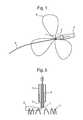
- FIGS. 10 to 13show a sequence of snapshots of collapsing the prosthetic heart valve into a compressed state.
- loops of filiform material 42pass through pairs of adjacent loops 40 of the support structure of the prosthesis 10 .
- the threads of filiform material 42pass out through the sheath 44 .
- the loops 40are gathered together as shown in FIG. 11 , and then the upper petal-like shapes of the prosthesis 10 collapse and can be withdrawn into the sheath 44 as shown in FIG. 12 . In this state, the lower petal-like shapes have also become folded.
- the structureis completely withdrawn into the sheath 44 as shown in FIG. 13 .
- the reverse sequence of FIGS. 10 to 13is performed and the sheath 44 is withdrawn away from the heart valve structure.
- the lower petal-like protrusionsexpand first as shown in FIG. 12 and enable the heart valve to be initially correctly positioned, including rotational positioning. Further withdrawal of the sheath 44 allows the heart valve to self-expand as shown in FIGS. 11 and 10 .
- the filiform material 42can be pulled again to collapse the structure into its compressed state, either partially or fully.
- the filiform material 42 and the sheath 44can be completely withdrawn via the reverse route through which access was obtained.
- the present inventionseeks to alleviate, at least partially, some or any of the above problems.
- a prosthesis delivery systemcomprising a sheath, at least one tether and a holder.
- the sheathdefines an axial direction.
- the at least one tetheris movable axially relative to the sheath.
- the holderis movable within the sheath, and is configured to constrain radially the at least one tether.
- a method of collapsing a prosthesis to a collapsed state in a sheathcomprises the steps of:
- a method of delivering a prosthesis collapsed in a sheath to a target positioncomprises the steps of:
- FIG. 1shows a prosthesis delivery system of an embodiment of the present invention
- FIGS. 2 to 4show the sequence of collapsing the prosthesis into the sheath of an embodiment of the delivery system of the present invention
- FIG. 5shows the step of detaching the at least one tether from the prosthesis
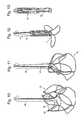
- FIGS. 6 to 9show the sequence of collapsing the prosthesis into the sheath of an embodiment of the delivery system of the present invention.
- FIGS. 10 to 13show the sequence of retrieving a heart valve back into the sheath as known in the prior art.
- FIG. 1depicts a schematic perspective view of an embodiment of the prosthesis delivery system.
- the apparatuscomprises a sheath 2 , at least one tether 4 and a holder 6 .
- the apparatusis connected to a guidewire 8 .
- FIG. 1depicts an embodiment of the apparatus, comprising an internal tube (i.e. holder 6 ), hosting one or more control thread loops (i.e. tethers 4 ), a guidewire 8 for endovascular guidance, and an external sheath 2 to collapse fully the prosthesis 10 and contain it in the collapsed configuration.
- an internal tubei.e. holder 6
- control thread loopsi.e. tethers 4
- guidewire 8for endovascular guidance
- an external sheath 2to collapse fully the prosthesis 10 and contain it in the collapsed configuration.
- the delivery system of the present inventioncomprises a holder 6 (which may take the form of a tube) within a sheath 2 (which may take the form of a tube).
- the tethers 4(which may comprise wires) are fed through the holder 6 and when the tethers 4 are pulled, the top loops of the prosthesis 10 (which may be a valve) draw together. Once in this position the prosthesis 10 can then be pulled into the sheath 2 and removed.
- the delivery system of the present inventionhas an advantage over delivery systems that do not have a holder 6 in that the risk of the top loops of the prosthesis 10 catching on the rim of the sheath 2 and jamming is reduced. Such undesirable catching and jamming can happen particularly if the top loops of the prosthesis 10 are not drawn together adequately when the prosthesis 10 is being pulled into the sheath 2 .
- the guidewire 8helps to control the movement of the apparatus through the vasculature of a living being.
- the apparatusis for delivering a prosthesis to an organ of a living being.
- the living beingmay be a mammal and, in particular, may be a human.
- the apparatusis a size suitable for being inserted into the vasculature of the living being.
- the sheath 2is longitudinal in shape and defines an axial direction.
- the sheath 2is for housing the prosthesis 10 when the prosthesis 10 is in a collapsed state.
- the sheath 2is configured to move through the vasculature of the living being.
- the purpose of the sheath 2is to protect the prosthesis 10 during its delivery from outside the living being to the organ.
- the prosthesis 10is collapsed to a compressed state and held within the sheath 2 on the guidewire 8 that is inserted into the vascular system through a catheter (not shown).
- the sheath 2may take the form of a tube open at both ends.
- the sheath 2is substantially cylindrical, having a substantially constant diameter throughout its axial (i.e. longitudinal) length.
- the diameter of the sheath 2is great enough such that the prosthesis 10 fits inside the sheath 2 when it is in the compressed state.
- the prosthesis 10when the prosthesis 10 is its expanded shape, the prosthesis 10 does not fit inside the sheath 2 .
- the sheath 2has an inner radial dimension smaller than the radial dimension of the prosthesis 10 in the expanded state.
- the diameter of the sheath 2is small enough such that it can fit inside the vascular system of the living being.
- the prosthesis 10is inserted into the sheath 2 and removed from the sheath 2 at one opening of the sheath 2 , which may be termed the lead end 3 of the sheath 2 .
- the at least one tether 4is movable axially relative to the sheath 2 .
- the apparatuscomprises a plurality of tethers 4 .
- the apparatusmay comprise three tethers 4 .
- the number of tethers 4 that may be usedis not particularly limited and may be two, four or more. In the following description, for clarity it will be assumed that there is a plurality of tethers 4 .
- the tethers 4are configured to attach to the prosthesis 10 .
- the tethers 4are configured to attach to the framework of the support structure of the prosthesis 10 .
- the tethers 4may extend along the length of the sheath 2 .
- the tethers 4are disposed within the sheath 2 .
- the tethers 4are configured to be extendable beyond the lead end 3 of the sheath 2 .
- the tethers 4are not integrally connected to the sheath 2 .
- the tethers 4are configured to attach to the prosthesis 10 at a lead end 5 of the tethers 4 .
- the tethers 4may be configured to be controllable so as to be detachable from the prosthesis 10 , via the end of the tethers 4 that is opposite to the lead end 5 of the tethers 4 .
- the purpose of thisis that when the prosthesis is attached to the delivery system via the tethers 4 and is in the correct place in the vascular system ready to be delivered, the prosthesis 10 can be left at the target position and the delivery system retrieved out of the body.
- the detachment of the tethers 4 from the prosthesis 10may be performed either by use of a guidewire attached the tethers 4 .
- Each tether 4may have its own guidewire, or a plurality of tethers 4 may share a single guidewire.
- the detachment of the tethers 4 from the prosthesis 10can be controlled by direct manipulation of the tethers 4 themselves.
- the tethers 4can be directly manipulated to detach from the prosthesis 10 in the case that the tethers 4 extend from the lead end 5 to a position outside the body of the living being.
- FIG. 5depicts such a construction.
- the tethers 4may comprise an unclosed loop of filiform material.
- the loopis formed at the lead end 5 of the tethers 4 .
- the two ends of the unclosed loop of filiform materialare at the opposite end (i.e. the control end) of the tethers 4 .
- the detachment of the tethers 4 from the prosthesis 10can be performed by manipulation at the open ends of the unclosed loop of filiform material.
- the tethers 4may comprise a hooked rib (i.e. a rib 12 with a hook 13 at its lead end).
- the hooked ribmay be attached to a guidewire for controlling the detachment of the tether 4 from the prosthesis 10 .
- the apparatusmay comprise a mixture of tethers 4 that comprise unclosed loops of filiform material and tethers 4 that comprise hooked ribs.
- the holder 6is movable axially within the sheath 2 .
- the holderis configured to constrain radially the tethers 4 .
- the purpose of the constrainingis to allow one end of the prosthesis 10 to be held by the tethers 4 in a collapsed state such that when the partially collapsed prosthesis 10 is fully inserted into the sheath 2 , the part of the prosthesis 10 that first enters the sheath 2 does not catch on the edges of the sheath 2 .
- the holder 6may hold the tethers 4 in a convergence region 7 .
- the convergence region 7may be within an aperture at the lead end 3 of the sheath 2 when viewed in the axial direction.
- the purpose of the convergence region 7is to allow one end of the prosthesis 10 to be collapsed in the convergence region 7 such that the collapsed end of the prosthesis 10 fits inside an aperture of the lead end 3 of the sheath 2 . For this reason, the convergence region 7 is within the internal region of the sheath 2 .
- the holder 6may encircle, or surround the tethers 4 when viewed in cross section.
- the holdergroups, or collects the tethers 4 together.
- the holder 6forms a closed loop when viewed in cross section.
- the radial constraint of the tethers 4 by the holder 6allows a clearance between the outside of the collapsed end of the prosthesis 10 (which is attached to the tethers 4 ) and the inner surface of the sheath 2 such that the collapsed end of the prosthesis 10 does not come into contact with the sheath 2 .
- parts of the prosthesis 10come into contact with the internal surface of the sheath 2 .
- the prosthesis 10can be partially collapsed such that the end of the prosthesis closest to the sheath 2 is collapsed and attached to the radially constrained tethers 4 such that the collapsed part of the prosthesis 10 does not catch on the sheath 2 as it is inserted. Subsequently, as the sheath 2 is forced around the rest of the prosthesis 10 (e.g. the uncollapsed part of the prosthesis 10 ), the prosthesis 10 does not become jammed, but is forced to collapse by the pressure of the sheath 2 .
- the convergence region 7is a region just beyond the lead end of the holder 6 .
- the lead ends 5 of the tethers 4constrain the collapsed end of the prosthesis 10 at the convergence region 7 .
- the convergence region 7may be a convergence area, within the cross sectional area of the sheath 2 when viewed in the axial direction.
- the sheath 2may have a cross sectional area consistent throughout its length. However, if the cross sectional area of the sheath 2 varies throughout its length, then the relevant cross sectional area is the cross sectional area of the sheath 2 at the lead end 3 of the sheath 2 .
- the lead end 3is the end at which the prosthesis 10 enters and exits the sheath 2 .
- FIGS. 2 to 4depict a method of collapsing a prosthesis 10 into the sheath 2 of the delivery system.
- the tethers 4comprise unclosed loops of filiform material.
- the present inventionmay also be implemented with tethers 4 comprising hooked ribs 12 , 13 .
- the loops of the tethers 4are attached to the prosthesis 10 .
- the prosthesismay comprise a support structure having a framework with distal cells.
- the distal cellshave apexes 11 .
- the support structureis collapsible from the fully expanded state into the compressed state by pulling on the apexes 11 . This enables the support structure to be drawn into the sheath 2 in the compressed state.
- the sheath 2has an inner radially dimension smaller than the radial dimension of the support structure in the expanded state.
- Each of the tethers 4forms a loop that passes through a number of the distal cells of the framework of the prosthetic device.
- the tethers 4are attached to the apexes 11 of the support structure of the prosthesis 10 at the lead end 5 of the tethers 4 .
- the tethers 4may be looped around one or more of the apexes 11 . In FIG. 2 , the two tethers 4 are depicted as being looped around three apexes 11 each.
- the method of collapsinginvolves constraining radially the tethers 4 with the holder 6 .
- the holder 6fits within the sheath 2 .
- the radial constraintresults in a clearance between the constrained section of the tethers 4 and the inner surface of the sheath 2 .
- the tethers 4are attached to the prosthesis 10 . This state is depicted in FIG. 2 .
- the tethers 4 and the holder 6are moved axially within the sheath 2 such that the prosthesis 10 is forced to collapse into the sheath 2 and the holder 6 is retracted into the sheath 2 .
- the resulting stateis depicted in FIG. 4 .
- the arrows in FIG. 4indicate the direction of movement of the sheath 2 relative to the holder 6 and the tethers 4 .
- the collapse of the device into the delivery systemmay be achieved by retracting the tethers 4 into and/or through the holder 6 , which may be an internal tube, in order to group the distal edges of the prosthesis frame in the convergence region 7 .
- the dimensions of the convergence region 7are smaller than the diameter of the external sheath 2 (see FIG. 3 ).
- the external sheath 2is advanced relatively to the prosthesis so as to force the prosthesis to collapse into it (see FIG. 4 ).
- This operationcan be repeated once the prosthesis 10 has been fully deployed into the target position of the anatomical region. This process may be performed so as to achieve the complete retrieval of the prosthesis 10 .
- the methodcomprises the step of retracting the tethers 4 relative to the holder 6 so as to collapse partially the prosthesis 10 such that the collapsed end of the prosthesis 10 fits within an aperture at the lead end 3 of the sheath 2 .
- the step of moving the tethers 4 and the holder 6 axially relative to the sheath 2is broken up into two stages.
- the prosthesis 10is partially collapsed such that one end of the prosthesis 10 fits within an aperture at the lead end 3 of the sheath 2 .
- the tethers 4are movable axially within the holder 6 .
- the tethers 4are pulled such that they are retracted into/towards the sheath 2 .
- the arrows in FIG. 3indicate the direction in which the tethers 4 are pulled.
- the end of the prosthesis 10 closest to the sheath 2collapses into the convergence region 7 because the tethers 4 are constrained radially by the holder 6 .
- the tethers 4 together with the holder 6are retracted into/through the sheath 2 .
- the collapsed end of the prosthesis 10enters into the lead end 3 of the sheath 2 without touching the edges of the sheath 2 .
- the collapsed apexes 11are retracted into the sheath 2 , other parts of the prosthesis 2 come into contact with the sheath 2 , thereby having the effect of forcing the rest of the prosthesis 10 to collapse into the sheath 2 .
- the lead ends 5 of the tethers 4are attached to the prosthesis 10 .
- This stepmay be performed outside the body of the living being. However, as explained in relation to FIGS. 6 to 9 , if a tether 4 comprising a hooked rib 12 , 13 is used, this step can be performed in the body of the living being.
- the holder 6may comprise a tube that is substantially co-axial with the sheath 2 .
- the holder 6does not necessarily have to take the form of a tube.
- the holder 6may comprise an annular ring.
- the holder 6is on a guidewire for endovascular guidance.
- the holder 6is different from the sheath 2 .
- the holder 6fits inside the sheath 2 .
- the holder 6may be in the sheath 2 .
- the holderis not attached to the sheath 2 .
- Theremay be a clearance gap between the outer surface of the holder 6 and the inner surface of the sheath 2 .
- the holder 6may be attached to the sheath 2 provided that the holder 6 is movable axially relative to the sheath 2 .
- the holder 6may be movable relative to the sheath 2 between an extended position (as depicted in FIG. 2 ) and a retracted position (see FIG. 4 ). In the extended position, a lead end of the holder 6 extends beyond a lead end 3 of the sheath 2 . In the retracted position, the lead end 3 of the sheath 2 extends beyond the lead end of the holder 6 .
- a lead end of the holder 6is configurable to extend beyond a lead end 3 of the sheath 2 .
- the holder 6may be initially positioned such that the convergence region 7 into which the collapsed apexes 11 are to be fit is extended beyond the lead end 3 of the sheath 2 .
- Thisallows the partially collapsed end of the prosthesis 10 to be collected away from the lead end 3 of the sheath 2 (see FIG. 3 ) before the sheath 2 is forced around the rest of the prosthesis 10 .
- the lead end of the holder 6is initially beyond the lead end 3 of the sheath 2 before being moved to be inside the sheath 2 (as shown in FIG. 4 ).
- the desired functionnamely collecting the collapsed end of the partially collapsed prosthesis 10 such that it does not come into contact with the sheath 2 when the process of forcing the prosthesis 10 into the sheath 2 is begun, can be performed by having the lead end of the holder 6 not extending beyond the lead end 3 of the sheath 2 .
- the collapsed end of the prosthesis 10forms a tapered shape, with the narrow section closest to the sheath 2 .
- the lead end of the holder 6it is possible for the lead end of the holder 6 to be slightly within the sheath 2 , while still having the collapsed end of the prosthesis 10 to be initially inserted into the sheath 2 without touching the sheath 2 .
- the lead end of the holder 6is retracted too far behind the lead end 3 of the sheath 2 , then it would not be possible to collapse one end of the prosthesis 10 such that it does not come into contact with the sheath 2 .
- the prosthesis 10When the prosthesis 10 is in the collapsed state within the sheath 2 as depicted in FIG. 4 , it is ready to be delivered to a target position of an anatomical region, for example in the heart of a living being.
- the sheath 2 with the collapsed prosthesis 10 inside itis entered into the vascular system of the living being via a catheter.
- the sheath 2is moved within the vascular system along the guidewire 8 .
- the method of delivering the prosthesis 10 to the target positioninvolves retracting the sheath 2 axially away from the prosthesis 10 that is attached to the tethers 4 . This results in the prosthesis 10 partially expanding from the collapsed state. This step is depicted in the transition from FIG. 4 to FIG. 3 .
- the tethers 4 to which the prosthesis 10 is attachedare constrained radially by the holder 6 . As a result, the prosthesis 10 is attached to the tethers 4 in the partially collapsed state.
- the delivery of the prosthesis 10further involves positioning in the target position the prosthesis 10 that is in the partially collapsed state and attached to the tethers 4 .
- the position of the prosthesis 10can still be controlled because it is still attached to the tethers 4 .
- the tension on the tethers 4is relaxed, thereby allowing the prosthesis 10 to fully expand (subject to the constraints of the vasculature in which it is situated).
- the deployment of the prosthesis 10is achieved by retracting the external sheath 2 , leaving the prosthesis 10 engaged only on the tethers 4 .
- the prosthesisis still firmly fixed to the delivery system, and can be manoeuvred and repositioned. Releasing the tension from the tethers 4 , the prosthesis 10 deploys fully. If necessary, the collapse sequence of operations can be repeated to retrieve the prosthesis 10 .
- the full expansion of the prosthesis 10is achieved by simply relaxing the tension on the tethers 4 .
- the delivery systemcan be moved away from the prosthesis 10 following the vascular route, keeping the tethers 4 connected to the prosthesis 10 .
- the valve positioning and haemodynamic performancecan be checked with state of the art techniques (e.g. by fluoroscopy, echocardiography and/or aorthography) and, if necessary, the catheter can be readvanced and the prosthesis 10 safely recollapsed and repositioned (or completely removed and exchanged for another solution) by pulling the tethers 4 .
- This feature of allowing the prosthesis 10 to expand fully while still being connected to the tethers 4means that it is not necessary for the delivery system to retrieve the valve to be kept in proximity of the prosthesis 10 . This reduces the possibility of the delivery system from interfering with the performance of the prosthesis 10 when these are verified.
- the tethers 4can be detached from the prosthesis 10 and extracted.
- FIG. 5depicts the prosthesis delivery system during a process of detaching the tether 4 from the prosthesis 10 .
- the tether 4comprises an unclosed loop of filiform material.
- the loopcan be detached from the prosthesis 10 by pulling on one of the open ends of the loop of filiform material. This unthreads the loop from the prosthesis 10 .
- the tethers 4may be removed from the apparatus by disengaging one of their terminations and retracting the other.
- FIG. 5two tethers 4 are depicted at different stages of detachment.
- the tether 4 shown in the left hand side of FIG. 4remains looped around apexes 11 of the prosthesis 10 .
- the tensionhas been released and one of its terminations is moving through the sheath 2 so as to pass through the apexes 11 , thereby detaching the tether 4 from the prosthesis 10 .
- An arrowis shown indicating the direction of movement of the other end of the tether 4 , namely away from the prosthesis 10 .
- the tether 4 shown in the right hand side of FIG. 4is at a later stage of detachment and is no longer attached to the prosthesis 10 . By pulling the tether 4 in the direction of the arrow, the tether 4 is removed completely from the delivery system.
- FIGS. 6 to 9depicts another embodiment of the present invention in which the tethers 4 comprise a hooked rib, 12 , 13 configured to be movable axially relative to the holder 6 .
- the hooked rib 12 , 13is configured to move between a collapsed position and an expanded position. In the collapsed position, which is depicted in FIG. 6 , the hooked rib 12 , 13 is held by the holder 6 in an elastically deformed state. In the expanded position, the hooked rib 12 , 13 extends radially beyond the holder 6 .
- the hooked rib 12 , 13comprises a hook 13 on the end of a rib 12 .
- the hook 13may be formed integrally with the rib 12 .
- the hook 13may be a separate member from the rib 12 , connected to the rib 12 .
- the hook 13is designed to attach to the prosthesis 10 .
- the prosthesis 10may comprise a permanent wire 14 , which is suitable for the hook 13 to attach to.
- the rib 12is formed of an elastic material.
- the ribs 12are constrained by the holder 6 .
- the hooked ribs 12 , 13are moved from the collapsed state to the expanded position (depicted in FIG. 7 ) the hooked ribs 12 , 13 extend beyond a lead end of the holder 6 .
- the hooked ribs 12 , 13extend through the holder 6 . Due to the elastic nature of the ribs 12 , the ribs extend radially beyond the holder 6 . This allows the ribs to be attached by the hooks 13 to the prosthesis 10 even when the prosthesis 10 is in its fully expanded position.
- an embodiment of the present inventioncomprises a holder 6 , which may comprise an internal tube, hosting one or more ribs 12 made terminating with hooks 13 (and a guidewire), and an external sheath 2 to collapse fully the prosthesis 10 and contain it in the collapsed configuration.
- the prosthesis 10may include a permanent wire passing through all distal cells of the framework of the support structure of the prosthesis.
- the process for collapsing the prosthesis into the sheath 2is similar to the process for the embodiments in which the tethers 4 comprise a loop of filiform material as described above.
- the tethers 4 comprising the hooked ribs 12 , 13are moved axially through the holder 6 so as to bring the lead end of the tethers 4 (i.e. the hooks 13 ) towards the holder 6 so as to collapse partially the prosthesis 10 .
- This stepis seen as a transition from the state depicted in FIG. 7 to the state depicted in FIG. 8 .
- the arrows in FIG. 8indicate the direction of movement of the tethers 4 relative to the holder 6 .
- the sheath 2is moved axially relative to the tethers 4 and the holder 6 such that the prosthesis 10 is forced to collapse into the sheath 2 and the holder 6 is retracted into the sheath 2 .
- the hooked ribs 12 , 13are advanced and expanded.
- the arrows in FIG. 7indicate the direction of advancement of the ribs 12 .
- the desired function of the ribs 12 to expand in this waymay be achieved by making the ribs 12 from a superelastic material.
- the hooked ribs 12 , 13engage their hooks 13 with the permanent wire 14 in one more points as depicted in FIG. 7 .
- the ribs 12are pulled back into the holder 6 , which may comprise a tube, thus retracting one or more portions of the permanent wire 14 of the prosthesis 10 .
- the permanent wire 14forms a number of loops that reduce in dimension, grouping the distal edge of the prosthesis frame to the convergence region 7 , which is dimensionally smaller than the diameter of the external sheath 2 , as depicted in FIG. 8 .
- the external sheath 2is advanced so as to force the prosthesis 10 to collapse into it, as depicted in FIG. 9 .
- An advantage of a delivery system that has tethers 4 comprising hooked ribs 12 , 13is that it allows retrieval and repositioning of the prosthesis 10 after the implantation procedure has been completed.
- the prosthesis delivery system of the present inventionmay be used in conjunction with any collapsible prosthetic device and is not limited to use with prosthetic heart valves.
- the average diameter of the prosthesis 10 when in the expanded stateis preferably in the range of from 10 to 40 mm, more preferably, the average diameter of the prosthesis 10 is in the range of from 18 to 32 mm.
- the diameter of the prosthesis when in the compressed stateis preferably less than 12 mm.
- a compressed prosthesis 10 of this sizeis suitable for transapical access, and more preferably, the diameter of the prosthesis when in the compressed state is less than 8 mm.
- the axial length of the prosthesis in the expanded stateis preferably in the range of from 12 to 200 mm, more preferably from 15 to 55 mm. When in the radially compressed state, the axial length occupied by the prosthesis is increased relative to its expanded state because of the way that the structure folds, however the increase in axial length is less than 100%, preferably less than 80%, and can be as little as 20%
Landscapes
- Health & Medical Sciences (AREA)
- Cardiology (AREA)
- Engineering & Computer Science (AREA)
- Biomedical Technology (AREA)
- Heart & Thoracic Surgery (AREA)
- Transplantation (AREA)
- Oral & Maxillofacial Surgery (AREA)
- Vascular Medicine (AREA)
- Life Sciences & Earth Sciences (AREA)
- Animal Behavior & Ethology (AREA)
- General Health & Medical Sciences (AREA)
- Public Health (AREA)
- Veterinary Medicine (AREA)
- Prostheses (AREA)
Abstract
Description
Claims (19)
Applications Claiming Priority (3)
| Application Number | Priority Date | Filing Date | Title |
|---|---|---|---|
| GB1017921.6 | 2010-10-22 | ||
| GBGB1017921.6AGB201017921D0 (en) | 2010-10-22 | 2010-10-22 | Prothesis delivery system |
| PCT/GB2011/001504WO2012052718A1 (en) | 2010-10-22 | 2011-10-19 | Prosthesis delivery system |
Publications (2)
| Publication Number | Publication Date |
|---|---|
| US20130296999A1 US20130296999A1 (en) | 2013-11-07 |
| US9597211B2true US9597211B2 (en) | 2017-03-21 |
Family
ID=43334289
Family Applications (1)
| Application Number | Title | Priority Date | Filing Date |
|---|---|---|---|
| US13/880,341Active2032-09-16US9597211B2 (en) | 2010-10-22 | 2011-10-19 | Prosthesis delivery system |
Country Status (4)
| Country | Link |
|---|---|
| US (1) | US9597211B2 (en) |
| EP (1) | EP2629700B2 (en) |
| GB (1) | GB201017921D0 (en) |
| WO (1) | WO2012052718A1 (en) |
Families Citing this family (75)
| Publication number | Priority date | Publication date | Assignee | Title |
|---|---|---|---|---|
| US20120041550A1 (en) | 2003-12-23 | 2012-02-16 | Sadra Medical, Inc. | Methods and Apparatus for Endovascular Heart Valve Replacement Comprising Tissue Grasping Elements |
| US9526609B2 (en) | 2003-12-23 | 2016-12-27 | Boston Scientific Scimed, Inc. | Methods and apparatus for endovascularly replacing a patient's heart valve |
| US8603160B2 (en) | 2003-12-23 | 2013-12-10 | Sadra Medical, Inc. | Method of using a retrievable heart valve anchor with a sheath |
| US11278398B2 (en) | 2003-12-23 | 2022-03-22 | Boston Scientific Scimed, Inc. | Methods and apparatus for endovascular heart valve replacement comprising tissue grasping elements |
| US20050137687A1 (en) | 2003-12-23 | 2005-06-23 | Sadra Medical | Heart valve anchor and method |
| US7959666B2 (en) | 2003-12-23 | 2011-06-14 | Sadra Medical, Inc. | Methods and apparatus for endovascularly replacing a heart valve |
| US8828078B2 (en) | 2003-12-23 | 2014-09-09 | Sadra Medical, Inc. | Methods and apparatus for endovascular heart valve replacement comprising tissue grasping elements |
| US7381219B2 (en) | 2003-12-23 | 2008-06-03 | Sadra Medical, Inc. | Low profile heart valve and delivery system |
| US8840663B2 (en) | 2003-12-23 | 2014-09-23 | Sadra Medical, Inc. | Repositionable heart valve method |
| DE102005003632A1 (en) | 2005-01-20 | 2006-08-17 | Fraunhofer-Gesellschaft zur Förderung der angewandten Forschung e.V. | Catheter for the transvascular implantation of heart valve prostheses |
| US20070213813A1 (en) | 2005-12-22 | 2007-09-13 | Symetis Sa | Stent-valves for valve replacement and associated methods and systems for surgery |
| EP1988851A2 (en) | 2006-02-14 | 2008-11-12 | Sadra Medical, Inc. | Systems and methods for delivering a medical implant |
| US7896915B2 (en) | 2007-04-13 | 2011-03-01 | Jenavalve Technology, Inc. | Medical device for treating a heart valve insufficiency |
| US9044318B2 (en) | 2008-02-26 | 2015-06-02 | Jenavalve Technology Gmbh | Stent for the positioning and anchoring of a valvular prosthesis |
| BR112012021347A2 (en) | 2008-02-26 | 2019-09-24 | Jenavalve Tecnology Inc | stent for positioning and anchoring a valve prosthesis at an implantation site in a patient's heart |
| EP3238661B1 (en) | 2008-10-10 | 2019-05-22 | Boston Scientific Scimed, Inc. | Medical devices and delivery systems for delivering medical devices |
| US8579964B2 (en) | 2010-05-05 | 2013-11-12 | Neovasc Inc. | Transcatheter mitral valve prosthesis |
| US10856978B2 (en) | 2010-05-20 | 2020-12-08 | Jenavalve Technology, Inc. | Catheter system |
| WO2011147849A1 (en) | 2010-05-25 | 2011-12-01 | Jenavalve Technology Inc. | Prosthetic heart valve and transcatheter delivered endoprosthesis comprising a prosthetic heart valve and a stent |
| AU2011300644B2 (en) | 2010-09-10 | 2015-08-20 | Symetis Sa | Valve replacement devices and a system comprising the valve replacement device and a delivery device therefor |
| CA2822381C (en) | 2010-12-23 | 2019-04-02 | Foundry Newco Xii, Inc. | System for mitral valve repair and replacement |
| US9308087B2 (en) | 2011-04-28 | 2016-04-12 | Neovasc Tiara Inc. | Sequentially deployed transcatheter mitral valve prosthesis |
| US9554897B2 (en) | 2011-04-28 | 2017-01-31 | Neovasc Tiara Inc. | Methods and apparatus for engaging a valve prosthesis with tissue |
| JP5872692B2 (en) | 2011-06-21 | 2016-03-01 | トゥエルヴ, インコーポレイテッド | Artificial therapy device |
| US8998976B2 (en) | 2011-07-12 | 2015-04-07 | Boston Scientific Scimed, Inc. | Coupling system for medical devices |
| US11202704B2 (en) | 2011-10-19 | 2021-12-21 | Twelve, Inc. | Prosthetic heart valve devices, prosthetic mitral valves and associated systems and methods |
| US9655722B2 (en) | 2011-10-19 | 2017-05-23 | Twelve, Inc. | Prosthetic heart valve devices, prosthetic mitral valves and associated systems and methods |
| EA201400478A1 (en) | 2011-10-19 | 2014-10-30 | Твелв, Инк. | DEVICES, SYSTEMS AND METHODS OF PROTESIZING THE HEART VALVE |
| US9763780B2 (en) | 2011-10-19 | 2017-09-19 | Twelve, Inc. | Devices, systems and methods for heart valve replacement |
| JP6133309B2 (en) | 2011-10-19 | 2017-05-24 | トゥエルヴ, インコーポレイテッド | Prosthetic heart valve device |
| US9039757B2 (en) | 2011-10-19 | 2015-05-26 | Twelve, Inc. | Prosthetic heart valve devices, prosthetic mitral valves and associated systems and methods |
| US9579198B2 (en) | 2012-03-01 | 2017-02-28 | Twelve, Inc. | Hydraulic delivery systems for prosthetic heart valve devices and associated methods |
| US9345573B2 (en) | 2012-05-30 | 2016-05-24 | Neovasc Tiara Inc. | Methods and apparatus for loading a prosthesis onto a delivery system |
| US10849755B2 (en) | 2012-09-14 | 2020-12-01 | Boston Scientific Scimed, Inc. | Mitral valve inversion prostheses |
| US9572665B2 (en) | 2013-04-04 | 2017-02-21 | Neovasc Tiara Inc. | Methods and apparatus for delivering a prosthetic valve to a beating heart |
| EP2999436B1 (en) | 2013-05-20 | 2018-08-29 | Edwards Lifesciences Corporation | Prosthetic heart valve delivery apparatus |
| AU2014268631B2 (en) | 2013-05-20 | 2019-08-01 | Twelve, Inc. | Implantable heart valve devices, mitral valve repair devices and associated systems and methods |
| CN105491978A (en) | 2013-08-30 | 2016-04-13 | 耶拿阀门科技股份有限公司 | Radially collapsible frame for a prosthetic valve and method for manufacturing such a frame |
| CN104257444A (en)* | 2014-10-17 | 2015-01-07 | 黄景陶 | Human body endoluminal stent implanting device capable of being recycled midway |
| US9848983B2 (en) | 2015-02-13 | 2017-12-26 | Millipede, Inc. | Valve replacement using rotational anchors |
| EP3270825B1 (en) | 2015-03-20 | 2020-04-22 | JenaValve Technology, Inc. | Heart valve prosthesis delivery system |
| US10709555B2 (en) | 2015-05-01 | 2020-07-14 | Jenavalve Technology, Inc. | Device and method with reduced pacemaker rate in heart valve replacement |
| GB2539444A (en) | 2015-06-16 | 2016-12-21 | Ucl Business Plc | Prosthetic heart valve |
| EP3175821A1 (en)* | 2015-12-02 | 2017-06-07 | Mitricares | Delivery apparatus for self-expanding medical device |
| US10238490B2 (en) | 2015-08-21 | 2019-03-26 | Twelve, Inc. | Implant heart valve devices, mitral valve repair devices and associated systems and methods |
| US10335275B2 (en) | 2015-09-29 | 2019-07-02 | Millipede, Inc. | Methods for delivery of heart valve devices using intravascular ultrasound imaging |
| CN111329541B (en)* | 2015-11-17 | 2023-09-19 | 波士顿科学国际有限公司 | Implantable devices and delivery systems for reshaping cardiac annulus |
| CA3007660A1 (en) | 2015-12-15 | 2017-06-22 | Neovasc Tiara Inc. | Transseptal delivery system |
| US10433952B2 (en) | 2016-01-29 | 2019-10-08 | Neovasc Tiara Inc. | Prosthetic valve for avoiding obstruction of outflow |
| WO2017189276A1 (en) | 2016-04-29 | 2017-11-02 | Medtronic Vascular Inc. | Prosthetic heart valve devices with tethered anchors and associated systems and methods |
| WO2017195125A1 (en) | 2016-05-13 | 2017-11-16 | Jenavalve Technology, Inc. | Heart valve prosthesis delivery system and method for delivery of heart valve prosthesis with introducer sheath and loading system |
| US10201416B2 (en) | 2016-05-16 | 2019-02-12 | Boston Scientific Scimed, Inc. | Replacement heart valve implant with invertible leaflets |
| CA3042588A1 (en) | 2016-11-21 | 2018-05-24 | Neovasc Tiara Inc. | Methods and systems for rapid retraction of a transcatheter heart valve delivery system |
| WO2018138658A1 (en) | 2017-01-27 | 2018-08-02 | Jenavalve Technology, Inc. | Heart valve mimicry |
| US10548731B2 (en) | 2017-02-10 | 2020-02-04 | Boston Scientific Scimed, Inc. | Implantable device and delivery system for reshaping a heart valve annulus |
| US10667934B2 (en)* | 2017-04-04 | 2020-06-02 | Medtronic Vascular, Inc. | System for loading a transcatheter valve prosthesis into a delivery catheter |
| US10702378B2 (en) | 2017-04-18 | 2020-07-07 | Twelve, Inc. | Prosthetic heart valve device and associated systems and methods |
| US10575950B2 (en) | 2017-04-18 | 2020-03-03 | Twelve, Inc. | Hydraulic systems for delivering prosthetic heart valve devices and associated methods |
| US10433961B2 (en)* | 2017-04-18 | 2019-10-08 | Twelve, Inc. | Delivery systems with tethers for prosthetic heart valve devices and associated methods |
| US10792151B2 (en) | 2017-05-11 | 2020-10-06 | Twelve, Inc. | Delivery systems for delivering prosthetic heart valve devices and associated methods |
| US10646338B2 (en) | 2017-06-02 | 2020-05-12 | Twelve, Inc. | Delivery systems with telescoping capsules for deploying prosthetic heart valve devices and associated methods |
| US10709591B2 (en) | 2017-06-06 | 2020-07-14 | Twelve, Inc. | Crimping device and method for loading stents and prosthetic heart valves |
| US10729541B2 (en) | 2017-07-06 | 2020-08-04 | Twelve, Inc. | Prosthetic heart valve devices and associated systems and methods |
| US10786352B2 (en) | 2017-07-06 | 2020-09-29 | Twelve, Inc. | Prosthetic heart valve devices and associated systems and methods |
| CA3073834A1 (en) | 2017-08-25 | 2019-02-28 | Neovasc Tiara Inc. | Sequentially deployed transcatheter mitral valve prosthesis |
| EP3784174B8 (en)* | 2018-04-24 | 2024-12-11 | Caisson Interventional, LLC | Systems for heart valve therapy |
| CN113271890B (en) | 2018-11-08 | 2024-08-30 | 内奥瓦斯克迪亚拉公司 | Ventricular deployment of transcatheter mitral valve prosthesis |
| CA3132873A1 (en) | 2019-03-08 | 2020-09-17 | Neovasc Tiara Inc. | Retrievable prosthesis delivery system |
| CA3135753C (en) | 2019-04-01 | 2023-10-24 | Neovasc Tiara Inc. | Controllably deployable prosthetic valve |
| US11491006B2 (en) | 2019-04-10 | 2022-11-08 | Neovasc Tiara Inc. | Prosthetic valve with natural blood flow |
| US11779742B2 (en) | 2019-05-20 | 2023-10-10 | Neovasc Tiara Inc. | Introducer with hemostasis mechanism |
| JP7520897B2 (en) | 2019-06-20 | 2024-07-23 | ニオバスク ティアラ インコーポレイテッド | Thin prosthetic mitral valve |
| DE102019121930A1 (en)* | 2019-08-14 | 2021-02-18 | Jotec Gmbh | Vascular prosthesis |
| US20210244916A1 (en)* | 2020-02-12 | 2021-08-12 | Cephea Valve Technologies, Inc. | Systems, methods, and devices for controlling re-sheathing forces |
| WO2024102411A1 (en) | 2022-11-09 | 2024-05-16 | Jenavalve Technology, Inc. | Catheter system for sequential deployment of an expandable implant |
Citations (12)
| Publication number | Priority date | Publication date | Assignee | Title |
|---|---|---|---|---|
| US5749921A (en)* | 1996-02-20 | 1998-05-12 | Medtronic, Inc. | Apparatus and methods for compression of endoluminal prostheses |
| US20020161377A1 (en)* | 2001-04-27 | 2002-10-31 | Dmitry Rabkin | Apparatus for delivering, repositioning and/or retrieving self-expanding stents |
| US20040138734A1 (en) | 2001-04-11 | 2004-07-15 | Trivascular, Inc. | Delivery system and method for bifurcated graft |
| US20050137686A1 (en)* | 2003-12-23 | 2005-06-23 | Sadra Medical, A Delaware Corporation | Externally expandable heart valve anchor and method |
| US20060173524A1 (en) | 2003-12-23 | 2006-08-03 | Amr Salahieh | Medical Implant Delivery And Deployment Tool |
| US7329279B2 (en) | 2003-12-23 | 2008-02-12 | Sadra Medical, Inc. | Methods and apparatus for endovascularly replacing a patient's heart valve |
| WO2009094189A1 (en) | 2008-01-24 | 2009-07-30 | Medtronic, Inc. | Delivery systems and methods of implantation for prosthetic heart valves |
| US20090270966A1 (en) | 2008-04-24 | 2009-10-29 | Medtronic Vascular, Inc. | Stent Graft System and Method of Use |
| US20100049313A1 (en) | 2008-08-22 | 2010-02-25 | Edwards Lifesciences Corporation | Prosthetic heart valve and delivery apparatus |
| WO2010042950A2 (en) | 2008-10-10 | 2010-04-15 | Sadra Medical, Inc. | Medical devices and delivery systems for delivering medical devices |
| WO2010079427A1 (en) | 2009-01-12 | 2010-07-15 | Valve Medical Ltd | Modular percutaneous valve structure and delivery method |
| WO2010112844A1 (en) | 2009-03-30 | 2010-10-07 | Ucl Business Plc | Heart valve prosthesis |
Family Cites Families (10)
| Publication number | Priority date | Publication date | Assignee | Title |
|---|---|---|---|---|
| US5957949A (en)† | 1997-05-01 | 1999-09-28 | World Medical Manufacturing Corp. | Percutaneous placement valve stent |
| US7452371B2 (en)† | 1999-06-02 | 2008-11-18 | Cook Incorporated | Implantable vascular device |
| US7011671B2 (en)† | 2001-07-18 | 2006-03-14 | Atritech, Inc. | Cardiac implant device tether system and method |
| US7399315B2 (en)† | 2003-03-18 | 2008-07-15 | Edwards Lifescience Corporation | Minimally-invasive heart valve with cusp positioners |
| FR2863160B1 (en)† | 2003-12-09 | 2006-03-03 | Perouse Laboratoires | DEVICE FOR TREATING A BLOOD VESSEL AND METHOD FOR PREPARING THE SAME |
| DE602005027608D1 (en)† | 2004-10-25 | 2011-06-01 | Merit Medical Systems Inc | DEVICE FOR REMOVING AND DISPLACING A STENT |
| EP1991168B1 (en)† | 2006-02-16 | 2016-01-27 | Transcatheter Technologies GmbH | Minimally invasive heart valve replacement |
| US8454683B2 (en)† | 2006-04-12 | 2013-06-04 | Medtronic Vascular, Inc. | Annuloplasty device having a helical anchor and methods for its use |
| EP2117469B1 (en)† | 2007-02-05 | 2014-07-09 | Boston Scientific Limited | Percutaneous valve system |
| US9149358B2 (en)† | 2008-01-24 | 2015-10-06 | Medtronic, Inc. | Delivery systems for prosthetic heart valves |
- 2010
- 2010-10-22GBGBGB1017921.6Apatent/GB201017921D0/ennot_activeCeased
- 2011
- 2011-10-19EPEP11778653.3Apatent/EP2629700B2/enactiveActive
- 2011-10-19USUS13/880,341patent/US9597211B2/enactiveActive
- 2011-10-19WOPCT/GB2011/001504patent/WO2012052718A1/enactiveApplication Filing
Patent Citations (14)
| Publication number | Priority date | Publication date | Assignee | Title |
|---|---|---|---|---|
| US5749921A (en)* | 1996-02-20 | 1998-05-12 | Medtronic, Inc. | Apparatus and methods for compression of endoluminal prostheses |
| US20040138734A1 (en) | 2001-04-11 | 2004-07-15 | Trivascular, Inc. | Delivery system and method for bifurcated graft |
| US20020161377A1 (en)* | 2001-04-27 | 2002-10-31 | Dmitry Rabkin | Apparatus for delivering, repositioning and/or retrieving self-expanding stents |
| US7824443B2 (en) | 2003-12-23 | 2010-11-02 | Sadra Medical, Inc. | Medical implant delivery and deployment tool |
| US20050137686A1 (en)* | 2003-12-23 | 2005-06-23 | Sadra Medical, A Delaware Corporation | Externally expandable heart valve anchor and method |
| US20060173524A1 (en) | 2003-12-23 | 2006-08-03 | Amr Salahieh | Medical Implant Delivery And Deployment Tool |
| US7329279B2 (en) | 2003-12-23 | 2008-02-12 | Sadra Medical, Inc. | Methods and apparatus for endovascularly replacing a patient's heart valve |
| WO2009094189A1 (en) | 2008-01-24 | 2009-07-30 | Medtronic, Inc. | Delivery systems and methods of implantation for prosthetic heart valves |
| US20090192585A1 (en) | 2008-01-24 | 2009-07-30 | Medtronic, Inc. | Delivery Systems and Methods of Implantation for Prosthetic Heart Valves |
| US20090270966A1 (en) | 2008-04-24 | 2009-10-29 | Medtronic Vascular, Inc. | Stent Graft System and Method of Use |
| US20100049313A1 (en) | 2008-08-22 | 2010-02-25 | Edwards Lifesciences Corporation | Prosthetic heart valve and delivery apparatus |
| WO2010042950A2 (en) | 2008-10-10 | 2010-04-15 | Sadra Medical, Inc. | Medical devices and delivery systems for delivering medical devices |
| WO2010079427A1 (en) | 2009-01-12 | 2010-07-15 | Valve Medical Ltd | Modular percutaneous valve structure and delivery method |
| WO2010112844A1 (en) | 2009-03-30 | 2010-10-07 | Ucl Business Plc | Heart valve prosthesis |
Non-Patent Citations (3)
| Title |
|---|
| Dictionary.com definition for "around" as accessed Aug. 10, 2016; http://www.dictionary.com/browse/around.* |
| International Search Report and Written Opinion issued in PCT/GB2011/001504, Dec. 23, 2011. |
| Search Report issued in GB Application No. 1017921.6, Dec. 21, 2010. |
Also Published As
| Publication number | Publication date |
|---|---|
| GB201017921D0 (en) | 2010-12-01 |
| EP2629700B1 (en) | 2017-04-19 |
| WO2012052718A1 (en) | 2012-04-26 |
| EP2629700B2 (en) | 2024-01-03 |
| US20130296999A1 (en) | 2013-11-07 |
| EP2629700A1 (en) | 2013-08-28 |
Similar Documents
| Publication | Publication Date | Title |
|---|---|---|
| US9597211B2 (en) | Prosthesis delivery system | |
| US20240268828A1 (en) | Devices and methods for effectuating percutaneous shunt procedures | |
| US10206799B2 (en) | Device and method for increasing flow through the left atrial appendage | |
| EP3468480B1 (en) | Sequential delivery of two-part prosthetic mitral valve | |
| EP3043748B1 (en) | A transcatheter valve delivery system with an alignment element | |
| US7815676B2 (en) | Apparatus and method for assisting in the removal of a cardiac valve | |
| EP1482861B1 (en) | An embolic protection system | |
| CN103857361B (en) | percutaneous heart valve delivery system | |
| US9968433B2 (en) | Embolic protection pass through tube | |
| JP7280939B2 (en) | Deployment system for implantable medical devices | |
| US10932932B2 (en) | Delivery device with an expandable positioner for positioning a prosthesis | |
| JP2012523908A (en) | Castered sleeve stent graft delivery system and method | |
| EP3225219B1 (en) | Distal capture device for a self-expanding stent | |
| EP3064176B1 (en) | Prosthesis delivery device | |
| US20230346536A1 (en) | Methods and systems for placing embolic filters in an aortic arch | |
| IE20030157A1 (en) | An embolic protection system |
Legal Events
| Date | Code | Title | Description |
|---|---|---|---|
| AS | Assignment | Owner name:UCL BUSINESS PLC, UNITED KINGDOM Free format text:ASSIGNMENT OF ASSIGNORS INTEREST;ASSIGNORS:BURRIESCI, GAETANO;TZAMTZIS, SPYRIDON;SEIFALIAN, ALEXANDER;SIGNING DATES FROM 20130503 TO 20130509;REEL/FRAME:030442/0728 | |
| STCF | Information on status: patent grant | Free format text:PATENTED CASE | |
| MAFP | Maintenance fee payment | Free format text:PAYMENT OF MAINTENANCE FEE, 4TH YR, SMALL ENTITY (ORIGINAL EVENT CODE: M2551); ENTITY STATUS OF PATENT OWNER: SMALL ENTITY Year of fee payment:4 | |
| AS | Assignment | Owner name:UCL BUSINESS LTD, UNITED KINGDOM Free format text:CHANGE OF LEGAL ENTITY;ASSIGNOR:UCL BUSINESS PLC;REEL/FRAME:061880/0332 Effective date:20190828 Owner name:FONDAZIONE RI.MED, ITALY Free format text:ASSIGNMENT OF ASSIGNORS INTEREST;ASSIGNOR:UCL BUSINESS LTD;REEL/FRAME:061650/0597 Effective date:20200902 | |
| MAFP | Maintenance fee payment | Free format text:PAYMENT OF MAINTENANCE FEE, 8TH YR, SMALL ENTITY (ORIGINAL EVENT CODE: M2552); ENTITY STATUS OF PATENT OWNER: SMALL ENTITY Year of fee payment:8 |