US9597152B2 - Control handles for medical devices - Google Patents
Control handles for medical devicesDownload PDFInfo
- Publication number
- US9597152B2 US9597152B2US13/608,002US201213608002AUS9597152B2US 9597152 B2US9597152 B2US 9597152B2US 201213608002 AUS201213608002 AUS 201213608002AUS 9597152 B2US9597152 B2US 9597152B2
- Authority
- US
- United States
- Prior art keywords
- distal end
- medical device
- opening
- scope
- control handle
- Prior art date
- Legal status (The legal status is an assumption and is not a legal conclusion. Google has not performed a legal analysis and makes no representation as to the accuracy of the status listed.)
- Expired - Fee Related
Links
Images


Classifications
- A—HUMAN NECESSITIES
- A61—MEDICAL OR VETERINARY SCIENCE; HYGIENE
- A61B—DIAGNOSIS; SURGERY; IDENTIFICATION
- A61B18/00—Surgical instruments, devices or methods for transferring non-mechanical forms of energy to or from the body
- A61B18/18—Surgical instruments, devices or methods for transferring non-mechanical forms of energy to or from the body by applying electromagnetic radiation, e.g. microwaves
- A61B18/20—Surgical instruments, devices or methods for transferring non-mechanical forms of energy to or from the body by applying electromagnetic radiation, e.g. microwaves using laser
- A61B18/22—Surgical instruments, devices or methods for transferring non-mechanical forms of energy to or from the body by applying electromagnetic radiation, e.g. microwaves using laser the beam being directed along or through a flexible conduit, e.g. an optical fibre; Couplings or hand-pieces therefor
- A61B18/26—Surgical instruments, devices or methods for transferring non-mechanical forms of energy to or from the body by applying electromagnetic radiation, e.g. microwaves using laser the beam being directed along or through a flexible conduit, e.g. an optical fibre; Couplings or hand-pieces therefor for producing a shock wave, e.g. laser lithotripsy
- A—HUMAN NECESSITIES
- A61—MEDICAL OR VETERINARY SCIENCE; HYGIENE
- A61B—DIAGNOSIS; SURGERY; IDENTIFICATION
- A61B17/00—Surgical instruments, devices or methods
- A61B17/22—Implements for squeezing-off ulcers or the like on inner organs of the body; Implements for scraping-out cavities of body organs, e.g. bones; for invasive removal or destruction of calculus using mechanical vibrations; for removing obstructions in blood vessels, not otherwise provided for
- A61B17/221—Gripping devices in the form of loops or baskets for gripping calculi or similar types of obstructions
- A—HUMAN NECESSITIES
- A61—MEDICAL OR VETERINARY SCIENCE; HYGIENE
- A61B—DIAGNOSIS; SURGERY; IDENTIFICATION
- A61B17/00—Surgical instruments, devices or methods
- A61B17/34—Trocars; Puncturing needles
- A61B17/3417—Details of tips or shafts, e.g. grooves, expandable, bendable; Multiple coaxial sliding cannulas, e.g. for dilating
- A61B17/3421—Cannulas
- A—HUMAN NECESSITIES
- A61—MEDICAL OR VETERINARY SCIENCE; HYGIENE
- A61B—DIAGNOSIS; SURGERY; IDENTIFICATION
- A61B17/00—Surgical instruments, devices or methods
- A61B17/22—Implements for squeezing-off ulcers or the like on inner organs of the body; Implements for scraping-out cavities of body organs, e.g. bones; for invasive removal or destruction of calculus using mechanical vibrations; for removing obstructions in blood vessels, not otherwise provided for
- A61B17/22004—Implements for squeezing-off ulcers or the like on inner organs of the body; Implements for scraping-out cavities of body organs, e.g. bones; for invasive removal or destruction of calculus using mechanical vibrations; for removing obstructions in blood vessels, not otherwise provided for using mechanical vibrations, e.g. ultrasonic shock waves
- A61B17/22012—Implements for squeezing-off ulcers or the like on inner organs of the body; Implements for scraping-out cavities of body organs, e.g. bones; for invasive removal or destruction of calculus using mechanical vibrations; for removing obstructions in blood vessels, not otherwise provided for using mechanical vibrations, e.g. ultrasonic shock waves in direct contact with, or very close to, the obstruction or concrement
- A—HUMAN NECESSITIES
- A61—MEDICAL OR VETERINARY SCIENCE; HYGIENE
- A61B—DIAGNOSIS; SURGERY; IDENTIFICATION
- A61B17/00—Surgical instruments, devices or methods
- A61B2017/0046—Surgical instruments, devices or methods with a releasable handle; with handle and operating part separable
- A61B2017/00469—Surgical instruments, devices or methods with a releasable handle; with handle and operating part separable for insertion of instruments, e.g. guide wire, optical fibre
- A—HUMAN NECESSITIES
- A61—MEDICAL OR VETERINARY SCIENCE; HYGIENE
- A61B—DIAGNOSIS; SURGERY; IDENTIFICATION
- A61B17/00—Surgical instruments, devices or methods
- A61B17/34—Trocars; Puncturing needles
- A61B17/3417—Details of tips or shafts, e.g. grooves, expandable, bendable; Multiple coaxial sliding cannulas, e.g. for dilating
- A61B17/3421—Cannulas
- A61B2017/3445—Cannulas used as instrument channel for multiple instruments
- A—HUMAN NECESSITIES
- A61—MEDICAL OR VETERINARY SCIENCE; HYGIENE
- A61B—DIAGNOSIS; SURGERY; IDENTIFICATION
- A61B90/00—Instruments, implements or accessories specially adapted for surgery or diagnosis and not covered by any of the groups A61B1/00 - A61B50/00, e.g. for luxation treatment or for protecting wound edges
- A61B90/06—Measuring instruments not otherwise provided for
- A61B2090/062—Measuring instruments not otherwise provided for penetration depth
Definitions
- the disclosurerelates generally to medical devices. Particular embodiments disclosed herein relate to control handles for medical devices, such as lithotripters. The disclosure also relates to methods of treatment.
- a lithotripsymay be performed in which a rigid probe attached to a firing handle is inserted into the bodily passage to fragment the stone. The procedure is accomplished by advancing the probe through a sheath disposed in the bodily passage, or the working channel of a scope, until the probe comes into contact with the stone. The firing handle is then activated to fire the probe and fragment the stone for removal.
- An exemplary method of removing a stone disposed within a salivary duct having a salivary duct openingcomprises a step of positioning a control handle on a medical device having a proximal end and a distal end. Another step comprises releasably attaching the control handle to the medical device. Another step comprises inserting the distal end of the medical device through said salivary duct opening such that the distal end of the medical device is disposed distal to said salivary duct opening and in said salivary duct. Another step comprises navigating the distal end of the medical device through said salivary duct and towards a point of treatment. Another step comprises contacting the distal end of the medical device with said stone disposed in said salivary duct. Another step comprises performing treatment using the medical device. Another step comprises withdrawing the medical device from said salivary duct.
- Another exemplary method of removing a stone disposed within a salivary duct having a salivary duct openingcomprises a step of positioning a control handle on a medical device having a proximal end and a distal end. Another step comprises releasably attaching the control handle to the medical device. Another step comprises inserting the distal end of the medical device into a lumen defined by a scope having a proximal end and a distal end such that the distal end of the medical device is disposed distal to the distal end of the scope.
- the lumen of the scopeextends between an opening at the proximal end of the scope and an opening at the distal end of the scope.
- Another stepcomprises inserting the distal end of the medical device through said salivary duct opening such that the distal end of the medical device is disposed distal to said salivary duct opening and in said salivary duct.
- Another stepcomprises inserting the distal end of the scope through said salivary duct opening such that the distal end of the scope is disposed distal to said salivary duct opening and in said salivary duct.
- Another stepcomprises navigating the distal end of the medical device through said salivary duct and towards a point of treatment.
- Another stepcomprises contacting the distal end of the medical device with said stone disposed in said salivary duct.
- Another stepcomprises performing treatment using the medical device.
- Another stepcomprises withdrawing the medical device from said salivary duct.
- An exemplary control handlecomprises a first portion, a second portion, and a compressible member.
- the first portionhas a proximal end, a distal end, a first shaft, a projection, and defines a recess and an aperture.
- the shaftextends from the proximal end towards the distal end of the first portion.
- the projectionextends from a location between the proximal end and the distal end to the distal end of the first portion.
- the recessextends into the projection from the distal end of the first portion towards the proximal end of the first portion to a recess base.
- the apertureextends from a first opening defined on the proximal end of the first portion to a second opening defined on the recess base.
- the second portionhas a proximal end, a distal end, a second shaft, and defines a recess and an aperture.
- the second shaftextends from the proximal end to the distal end of the second portion.
- the recessextends into second shaft and from the proximal end towards the distal end of the second portion to a recess base.
- the apertureextends from a first opening defined on the recess base of the second portion to a second opening defined on the distal end of the second portion.
- the compressible memberhas a proximal end and a distal end. A portion of the compressible member is disposed within one of the recess defined by the first portion or the recess defined by the second portion.
- the first portionis adapted to be releasably attached to the second portion.
- the projectionis adapted to be received by the recess defined by the second portion.
- the control handleis moveable between a first configuration and a second configuration. In the first configuration, the projection is free of the recess of the second portion. In the second configuration, the projection is disposed within the recess of the second portion and the first portion is releasably attached to the second portion.
- FIG. 1is an exploded side view of an exemplary control handle.
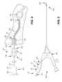
- FIG. 2is a side view of an exemplary control handle disposed on a probe.
- FIG. 3is a side view of an exemplary control handle disposed on a probe that has been advanced through a scope.
- FIG. 3Ais another side view of an exemplary control handle disposed on a probe that has been advanced through a scope.
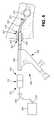
- FIG. 4is a partial cross sectional view of the exemplary control handle illustrated in FIG. 1 disposed on a probe that has been advanced through a sheath disposed in the opening of a salivary duct.
- FIG. 5is a side view of the exemplary control handle illustrated in FIG. 1 disposed on a probe that has been advanced through a scope.
- FIG. 6is a side view of the exemplary control handle illustrated in FIG. 1 disposed on a laser fiber that has been advanced through a scope and a sheath disposed in the opening of a salivary duct.
- FIG. 7is an exploded side view of a second exemplary control handle.
- FIG. 8is a side view of a third exemplary control handle.
- FIG. 9is a perspective view of a fourth exemplary control handle in a first configuration.
- FIG. 10is a side view of the exemplary control handle illustrated in FIG. 9 in a second configuration.
- FIG. 11is a side view of a fifth exemplary control handle in a first configuration.
- FIG. 12is a side view of the fifth exemplary control handle in a second configuration.
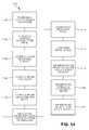
- FIG. 13is a flowchart representation of an exemplary method of treatment.
- FIG. 14is a flowchart representation of another exemplary method of treatment.
- salivary ductrefers to the parotid ducts, submandibular ducts, and/or sublingual ducts.
- exemplaryrefers to “an example of” and is not intended to convey a meaning of an ideal or preferred embodiment.
- FIG. 1illustrates an exemplary detachable control handle 100 comprising a proximal end 102 , a distal end 104 , a first portion 120 , and a second portion 140 .
- the control handle 100has a first configuration and a second configuration, each described in more detail below.
- the first portion 120comprises a proximal end 122 , distal end 124 , shaft 126 , threaded portion 128 , and one or more projections 130 .
- the shaft 126extends from the proximal end 122 towards the distal end 124 .
- the threaded portion 128extends from distal end of the shaft 126 towards the distal end 124 .
- the one or more projections 130extend from a location between the proximal end 122 and the distal end 124 of the first portion 120 to the distal end 124 of the first portion 120 .
- the one or more projections 130extend about the entirety, or a portion of, the circumference of the distal end of the threaded portion 128 to the distal end 124 of the first portion 120 .
- the one or more projections 130form a collet configuration that extends from the distal end of the threaded portion 128 to the distal end 124 of the first portion 120 .
- the one or more projections 130can optionally comprise one or more teeth and or ridges on a portion, or the entirety, of the interior surface of the one or more projections 130 .
- the body of the shaft 126 and threaded portion 128define aperture 132 , which extends from the proximal end 122 to the distal end of the threaded portion 128 between the proximal end 122 and the distal end 124 of first portion 120 .
- the aperture 132provides access through the length of the first portion 120 .
- the second portion 140comprises a proximal end 142 , distal end 144 , and a shaft 146 that defines a recess 148 and an aperture 152 .
- the shaft 146extends from the proximal end 142 to the distal end 144 of the second portion 140 .
- the recess 148extends from the proximal end 142 into the body of the shaft 146 towards the distal end 144 to base 145 .
- the wall of the recess 148defines threaded portion 150 that extends from the proximal end 142 towards the distal end 144 of the second portion 140 .
- the recess 148has a tapered configuration from its proximal end to its distal end at base 145 and is adapted to receive the threaded portion 128 and the one or more projections 130 of the first portion 120 .
- the body of the shaft 146defines aperture 152 that extends from the base 145 of the recess 148 to the distal end 142 of the second portion 140 .
- the control handle 100can be formed of any suitable material and using any suitable method of manufacture.
- Example materials considered suitableinclude, but are not limited to, metals, plastics, or variations thereof, biocompatible materials, materials that can be made biocompatible, and any other material considered suitable for a particular application.
- first portion 120has been described as having threaded portion 128 and the second portion 140 has been described as having threaded portion 150
- other methods of providing releasable attachment between the two componentsare considered suitable, and skilled artisans will be able to select an appropriate type of attachment based on various considerations, such as the outside diameter of the probe, or other device, being utilized.
- Example methods of attachment considered suitable between the first portion and the second portioninclude, but are not limited to, providing a snap fit, pin vice, and/or a Morse taper.
- control handle 100has been illustrated as having a particular external structural arrangement, a control handle can have any suitable external structural arrangement, and skilled artisans will be able to select a suitable external structural arrangement for a control handle according to a particular embodiment based on various considerations, including the structural arrangement of the device upon which the control handle is intended to be used.
- Example external structural arrangements considered suitableinclude, but are not limited to, linear, round, elliptical, oblong, tapered first portion and/or second portion, and any other structural arrangement considered suitable for a particular application.
- FIG. 2illustrates the exemplary detachable control handle 100 disposed on a probe 200 comprising a proximal end 201 , a distal end 202 , and a length that extends between the proximal end 201 and the distal end 202 .
- the control handle 100is disposed along the length of the probe 200 by inserting the distal end 202 of the probe 200 through the aperture 132 of the first portion 120 and the aperture 152 of the second portion 140 .
- control handle 100can be disposed along the length of the probe 200 by inserting the distal end 202 of the probe 200 through the aperture 152 of the second portion 140 and the aperture 132 of the first portion 120 .
- the threaded portion 128 of the first portion 120is free of the threaded portion 150 of the second portion 140 and the control handle 100 is slidably disposed along the length of the probe 200 .
- the first portion 120 along the length, or a portion of the length, of the one or more projections 130is in a first state and has a first inside diameter.
- the first inside diameter in the first stateis greater than, or slightly greater than, the outside diameter of the probe 200 , allowing for the first portion 120 to be moveable along the length of the probe 200 .
- the threaded portion 128 of the first portion 120is engaged with the threaded portion 150 of the second portion 140 such that the one or more projections 130 (e.g., collet configuration) are disposed within the recess 148 of the second portion 140 .
- the tapered configuration of the recess 148compresses the distal end, a portion, or the entirety, of the one or more projections 130 against a portion of the exterior surface of the probe 200 to engage and/or lock the control handle 100 in place along the length of the probe 200 .
- the first portion 120 along the length, or a portion of the length, of the one or more projections 130is in a second state and has a second inside diameter.
- the second inside diameter in the second stateis equal to, or substantially equal to, the outside diameter of the probe 200 , or is less than the inside diameter in the first state, allowing for the one or more projections 130 to engage and/or lock the control handle 100 in place along the length of the probe 200 .
- the control handle 100is releasably attached to the probe 200 .
- the configuration of the control handle 100advantageously allows for removing the control handle 100 from the probe 200 and/or adjusting the position of the control handle 100 along the length of the probe 200 .
- a usermoves the control handle 100 from the second configuration to the first configuration, or a position between the second configuration and the first configuration, and slides the control handle 100 to a desired position along the length of the probe 200 .
- the usermoves the control handle 100 back to the second configuration.
- the usermoves the control handle 100 from the second configuration to the first configuration, or a position between the second configuration and the first configuration, and slides the control handle 100 off of the probe 200 .
- the probe 200optionally comprises one or more indicia (e.g., markers) disposed along its length.
- Each of the one or more indiciacorrelates with a length of probe that extends distal and/or proximal to the one or more indicia.
- any form of measurementcan be utilized to indicate to a user a length of probe disposed distal to the one or more indicia.
- the one or more indiciaassist a user in determining the length of the probe 200 disposed within a bodily passage.
- the one or more indiciacan be embedded within, and/or disposed on the interior or exterior surface of the probe 200 .
- each of the one or more indiciacan comprise a raised protuberance extending radially outward from the exterior surface of the probe 200 .
- the raised protuberancecan extend about the entirety of the circumference, or a portion of the circumference, of the probe 200 .
- the inclusion of a raised protuberanceis considered advantageous at least because it provides a user with tactile feedback as to the disposition of the control handle 100 along the length of the probe 200 as it is being releasably attached to the probe 200 , allowing a user to releasably attached the control handle 100 at a particular location on the probe 200 .
- control handle 100can optionally comprise one or more recesses that circumferentially extend around the entirety, or a portion, of the interior surface of the first portion 120 and/or second portion 140 and are adapted to receive the one or more raised protuberances and position the control handle 100 at a particular location along the length of the probe 200 .
- the probe 200can also optionally comprise a roughened surface along the entirety, or a portion, of the length of the probe 200 .
- the inclusion of a roughened surface along the entirety, or a portion, of the length of the probe 200is considered advantageous at least because it decreases the likelihood of the control handle 100 sliding from its position during use.
- the roughened surfacecan be accomplished in any suitable manner.
- Example methods considered suitable for producing a roughened surface along the entirety, or a portion, of the length of the probe 200include, but are not limited to, grit blasting, sanding, and/or etching.
- the probe 200can be attached to any suitable device for performing treatment within a bodily passage.
- the probe 200can be attached to a medical device such as a pneumatic lithotripter, ultrasonic lithotripter, and/or drill.
- control handle 100can be attached to a laser fiber that is attached to a medical device such as a laser lithotripter. While particular medical devices have been described, the probe 200 and/or control handle 100 can be attached to any suitable medical device, and skilled artisans will be able to select an appropriate medical device according to a particular embodiment based on various considerations, such as the type of procedure being performed.
- Example medical devices considered suitable to include a control handleinclude, but are not limited to, probes, lithotripsy probes, optics, fiber optics, fibers, laser fibers, suction devices, irrigation devices, baskets, stone baskets, graspers, forceps, grasping forceps, drills, balloons, balloon catheters, and any other device considered suitable for a particular application (e.g., to treat a salivary duct).
- the control handle 100advantageously provides a user with fine motor control of the probe 200 and tactile feedback relating to the treatment area and/or bodily passage.
- FIG. 3illustrates fine motor control over the probe 200 using the detachable control handle 100 .
- the probe 200has been advanced through scope 250 .
- FIG. 3Aillustrates the fine motor control the right hand 251 of the user has over the probe 200 using the detachable control handle 100 and the gross motor control the left hand 252 has over the firing handle 260 .
- Fine motor controlis considered advantageous at least because it allows a user to properly position the distal end 204 of the probe 200 prior to activating the firing handle 260 .
- the control handle 100provides a user with the ability to finely control the advancement of the probe 200 and provides tactile feedback as to when the probe 200 is in contact with a stone. Tactile feedback is considered advantageous at least because it allows a user to confirm proper placement of the probe 200 prior to activating the firing handle 260 of the lithotripter.
- FIG. 4illustrates the exemplary control handle 100 illustrated in FIG. 1 disposed on a probe 200 that has been advanced through a sheath 300 disposed in the opening of a salivary duct 320 .
- the control handle 100in addition to providing adjustability along the length of the probe 200 and tactile feedback, the control handle 100 also provides a user with the ability to control the length of the probe 200 that is passed into a bodily passage, such as a salivary duct.
- FIG. 4illustrates a sheath 300 disposed in the opening of a bodily passage to allow for the passage of treatment devices into the bodily passage.
- the sheath 300comprises a proximal end 302 , a distal end 304 , and defines a lumen 306 that extends between an opening at the proximal end 302 and an opening at the distal end 304 .
- the bodily passageis a salivary duct 320 , however it is considered suitable to utilize the control handles and/or probe configurations described herein in any bodily passage.
- the salivary duct 320has a stone 340 disposed in its length.
- the distal end 104 of the control handle 100acts as a mechanical stop by interacting with the proximal end 302 of the sheath, preventing advancement of the probe 200 beyond the position of the control handle 100 .
- the length of the probe 200 located distal to the control handle 100is disposed through the lumen 306 of the sheath 300 and in the salivary duct 320 .
- sheath 300can be omitted and control handle 100 can interact with the wall of the bodily passage.
- the distal end 202 of the probe 200has been inserted through the proximal end and lumen of the scope 400 and the distal end 104 of the control handle 100 is acting as a mechanical stop by preventing advancement of the probe 200 beyond the position of the control handle 100 .
- the length of the probe 200 located distal to the control handle 100is disposed through the lumen of the scope 400 , leaving the scope 400 disposed between the distal end 202 of the probe 200 and the distal end 104 of the control handle 100 .
- FIG. 6illustrates a side view of the exemplary control handle 100 illustrated in FIG. 1 disposed on a laser fiber 500 that has been advanced through a scope 400 and a sheath 300 disposed in the opening of a salivary duct 320 .
- the sheath 300is similar to sheath 300 illustrated in FIG. 4 , and described above, except as detailed below.
- the scope 400is similar to scope 400 illustrated in FIG. 5 , and described above, except as detailed below.
- Reference numbers in FIG. 6refer to the same structural element or feature referenced by the same number in FIGS. 4 and 5 .
- sheath 300has a proximal end 302 , a distal end 304 , and defines a lumen 306 and scope 400 has a proximal end 402 , a distal end 404 , and defines a lumen 406 that extends from an opening on the proximal end 402 to an opening on the distal end 404 .
- sheath 300is disposed in the opening of a salivary duct 320 and the distal end 404 of scope 400 has been advanced through the lumen 306 defined by the sheath 300 and towards a point of treatment (e.g., stone 340 ).
- Control handle 100is disposed along the length of a laser fiber 500 that has a proximal end 502 and a distal end 504 .
- the proximal end 502 of the laser fiber 500is operatively attached to an energy source 506 that is adapted to transmit energy along the length of the laser fiber 500 .
- the control handle 100is disposed between the proximal end 502 and the distal end 504 of the laser fiber 500 such that when the distal end 504 of the laser fiber 500 has been inserted through lumen 406 defined by scope 400 the distal end 104 of the control handle 100 acts as a mechanical stop by preventing advancement of the laser fiber 500 through the scope 400 beyond the position of the control handle 100 .
- the length of the laser fiber 500 located distal to the control handle 100can be advanced through lumen 406 define by the scope 400 , sheath 300 , and salivary duct 320 .
- sheath 300can be omitted and scope 400 can independently be advanced through the opening of a bodily passage.
- Any suitable laser fiber 500 and/or energy source 506can be used in combination with control handle 100 , and skilled artisans will be able to select a suitable laser fiber and/or energy source according to a particular embodiment based on various considerations, including the type of procedure intended to be completed.
- the wall of the first portion 620defines threaded portion 628 between the proximal end 622 and distal end 624 , projection 630 , and a recess 670 that extends into the body of projection 630 from the distal end 624 and towards the proximal end 622 to a recess base 672 .
- projection 630can be omitted and recess 670 can extend into threaded portion 628 .
- control handle 600includes a compressible member 680 and a rigid member 690 .
- Compressible member 680has a proximal end 682 , a distal end 684 , and defines a lumen 686 that extends from an opening on the proximal end 682 to an opening on the distal end 684 .
- Rigid member 690has a proximal end 692 , a distal end 694 , and defines a lumen 696 that extends from an opening on the proximal end 692 to an opening on the distal end 694 .
- Compressible member 680can comprise any suitable compressibility and rigid member 690 can comprise any suitable rigidity.
- Compressible member 680need only be compressible relative to rigid member 690 .
- Compressible member 680 and rigid member 690can be formed of any suitable material, and skilled artisans will be able to select a suitable material for a compressible member and/or a rigid member according to a particular embodiment based on various considerations, including the material forming a control handle.
- Example materials considered suitable to form a compressible memberinclude, but are not limited to, biocompatible materials, materials that can be made biocompatible, polymers, flexible polymers, materials that are deformable, and any other material considered suitable for a particular application.
- Example materials considered suitable to form a rigid memberinclude, but are not limited to, biocompatible materials, materials that can be made biocompatible, polymers, rigid polymers, metals, and any other material considered suitable for a particular application.
- Compressible member 680is disposed within recess 670 such that the proximal end 682 of compressible member 680 is disposed adjacent recess base 672 .
- Rigid member 690is disposed within recess 670 such that the proximal end 692 of rigid member 690 is disposed adjacent the distal end 684 of compressible member 680 and the distal end 694 of the rigid member 690 is disposed adjacent the recess base 645 of the second portion 640 .
- control handle 600When control handle 600 is moved to its second configuration, in which first portion 620 and second portion 640 are releasably attached to one another, the distal end 694 of rigid member 690 contacts recess base 645 of second portion 640 and the proximal end 692 of rigid member 690 compresses against the distal end 684 of compressible member 680 . As first portion 620 is threaded onto second portion 640 , or vice versa, rigid member 690 is compressed against compressible member 680 such that compressible member 680 deforms and the lumen 686 defined by compressible member 680 is reduced in diameter such that it grips any device passing through lumen 632 and/or lumen 652 . Thus, when control handle 600 is in the first configuration lumen 686 defines a first inner diameter and when control handle 600 is in the second configuration lumen 686 defines a second inner diameter that is less than the first inner diameter.
- compressible member 680 and rigid member 690have been illustrated and described as being disposed within recess 670 such that the proximal end 682 of compressible member 680 is disposed adjacent recess base 672 and the proximal end 692 of rigid member 690 is disposed adjacent the distal end 684 of compressible member 680
- any suitable configurationis considered suitable.
- rigid member 690can be disposed within recess 670 such that the proximal end 692 of rigid member 690 is disposed adjacent recess base 672 and compressible member can be disposed within recess 670 such that the proximal end 682 of compressible member 680 is disposed adjacent the distal end 694 of rigid member 690 .
- a portion of compressible member 680 and/or rigid member 690can be disposed within one or the recess 670 defined by the first portion 620 or the recess 648 defined by the second portion 640 .
- compressible member 680 and rigid member 690have been illustrated and described as providing a mechanism for releasably attaching control handle 600 to a device (e.g., probes, lithotripsy probes, optics, fiber optics, fibers, laser fibers, suction devices, irrigation devices, baskets, stone baskets, graspers, forceps, grasping forceps, drills, balloons, balloon catheters), releasable attachment between a control handle and a device can be accomplished using any suitable number of compressible members and/or rigid members.
- a devicee.g., probes, lithotripsy probes, optics, fiber optics, fibers, laser fibers, suction devices, irrigation devices, baskets, stone baskets, graspers, forceps, grasping forceps, drills, balloons, balloon catheters
- releasable attachment between a control handle and a devicecan be accomplished using any suitable number of compressible members and/or rigid members.
- FIG. 8illustrates a third exemplary control handle 700 comprising a body 702 and a fastener 704 .
- Body 702comprises a proximal end 706 , a distal end 708 , and defines a first lumen 710 and a second lumen 712 .
- First lumen 710extends from a first opening 714 defined on the proximal end 706 to a second opening 716 defined on the distal end 708 .
- Second lumen 712extends from a first opening 718 defined between the proximal end 706 and the distal end 708 to a second opening 720 defined along the length of first lumen 710 .
- Second lumen 712is in communication with first lumen 710 .
- Second lumen 712is threaded along its length, or a portion thereof, and is adapted to receive a portion of fastener 704 .
- Fastener 704has a first end 730 and a second end 732 and is threaded from the second end 732 towards the first end 730 .
- Control handle 700has a first configuration and a second configuration.
- fastener 704is disposed between opening 718 and opening 720 and in the second configuration fastener 704 is disposed within opening 720 and/or within lumen 710 .
- a devicee.g., probe 200 , laser fiber 500
- Fastener 704is then advanced through second lumen 712 towards first lumen 710 until it contacts and compresses against the device attaching control handle 700 to the device.
- Control handle 700can be formed of any suitable material using any suitable method of manufacture, and skilled artisans will be able to select a suitable material and method of manufacture according to a particular embodiment based on various considerations, including the material forming the device on which the control handle is intended to be used.
- Example materials considered suitableinclude, but are not limited to, biocompatible materials, materials that can be made biocompatible, metals, polymers, flexible materials, and any other material considered suitable for a particular application.
- FIGS. 9 and 10illustrate a fourth exemplary control handle 800 comprising a first portion 802 and a second portion 804 .
- Control handle 800has a first configuration, as illustrated in FIG. 9 , and a second configuration, as illustrated in FIG. 10 .
- First portion 802has a proximal end 806 , a distal end 808 , and a body 810 that has a first side 812 and defines a recess 814 and a protuberance 816 .
- First side 812extends from the proximal end 806 to the distal end 808 of first portion 802 and is complementary to second side 826 of second portion 804 .
- Recess 812extends from the proximal end 806 to the distal end 808 of first portion 802 and into body 810 from first side 812 .
- Protuberance 816extends radially outward from first side 812 and has a lip 818 that extends towards recess 812 .
- Second portion 804has a proximal end 820 , a distal end 822 , and a body 824 that has a second side 826 and defines a first recess 828 and a second recess 830 .
- Second side 826extends from the proximal end 820 to the distal end 822 of second portion 804 and is complementary to first side 812 of first portion 802 .
- First recess 828extends from the proximal end 820 to the distal end 822 of second portion 804 and into body 824 from second side 826 .
- Second recess 830extends into body 824 between the proximal end 820 and distal end 822 of second portion 804 and is adapted to receive a portion or the entirety of lip 818 .
- Example number of hinges considered suitableinclude, but are not limited to, at least one, one, two, a plurality, three, four, and any other number considered suitable for a particular application.
- Example type of hinges considered suitableinclude, but are not limited to, hinges formed integrally with the first portion and the second portion, and any other type of hinge considered suitable for a particular application.
- a devicee.g., probe 200 , laser fiber 500
- a deviceis placed between the first portion 802 and second portion 804 when control handle 800 is in the first configuration such that the control handle 800 is disposed between the proximal end of the device and the distal end of the device.
- Control handle 800is then moved to its second configuration such that it compresses against the device attaching control handle 800 to the device.
- FIGS. 11 and 12illustrate a fifth exemplary control handle 900 comprising a body 902 and an actuator 904 .
- Control handle 900has a first configuration, as illustrated in FIG. 11 , and a second configuration, as illustrated in FIG. 12 .
- Body 902has a proximal end 906 , a distal end 908 , and defines a lumen 910 , an opening 912 , and a plurality of arms 914 .
- Lumen 910extends from a first opening 916 on the proximal end 906 to second opening 918 on the distal end 908 .
- Opening 912is disposed between the proximal end 906 and the distal end 908 , extends through the body 902 , and is in communication with lumen 910 .
- Each arm of the plurality of arms 914extends from body 902 into lumen 910 and towards the distal end 908 of body 902 to an arm distal end 919 .
- Each arm of the plurality of arms 914is pivotably connected to body 902 such that it can move from a first position to a second position.
- Actuator 904has a first end 920 and a second end 922 and is slidable along the length of body 902 .
- First end 920is disposed on the exterior surface of body 902 and the second end 922 is disposed within lumen 910 .
- the body of actuator 904defines an aperture 924 between the first end 920 and second end 922 of actuator 904 that is disposed within lumen 910 and is adapted to receive each arm of the plurality of arms 914 and a device on which control handle 900 is intended to be releasably attached.
- Actuator 904has a first configuration, as shown in FIG. 11 , and a second configuration, as shown in FIG. 12 .
- Control handle 900can be formed of any suitable material and using any suitable method of manufacture, and skilled artisans will be able to select a suitable material and method of manufacture according to a particular embodiment based on various considerations, including the material forming the device on which a control handle is intended to be used.
- Example materials considered suitableinclude, but are not limited to, metals, polymers, flexible materials, biocompatible materials, materials that can be made biocompatible, and any other material considered suitable for a particular application.
- a devicee.g., probe 200 , laser fiber 500
- actuatoris placed within lumen 910 when actuator is in the first configuration and each arm of the plurality of arms 914 is in the first position such that the control handle 900 is disposed between the proximal end of the device and the distal end of the device.
- Actuator 900is then moved to its second configuration such that it moves each arm of the plurality of arms 914 to its second position attaching control handle 900 to the device.
- control handlee.g., control handle 100 , control handle 600 , control handle 700 , control handle 800 , control handle 900
- other configurationsare considered suitable, and skilled artisans will be able to select an appropriate configuration for a control handle according to a particular embodiment based on various considerations, such as the outside diameter of the device (e.g., probe, laser fiber) upon which the control handle is intended to be used.
- the outside diameter of the devicee.g., probe, laser fiber
- Examples of alternative control handle configurations considered suitableinclude, but are not limited to, pin clamps, locking torque device, tubular members, and/or tubular members that comprise a setscrew.
- FIG. 13is a flowchart representation of an exemplary method 1000 of treatment.
- a step 1002comprises positioning a control handle on a medical device at a predetermined location.
- the medical devicecomprising a proximal end and a distal end.
- Another step 1004comprises releasably attaching the control handle to the medical device.
- Another step 1006comprises inserting a sheath having a proximal end and a distal end through an opening in a bodily passage such that the distal end of the sheath is disposed past the opening and in the bodily passage.
- the sheathdefines a lumen that extends between an opening at the proximal end and an opening at the distal end of the sheath.
- Another step 1008comprises inserting the distal end of the medical device into a lumen defined by a scope having a proximal end and a distal end such that the distal end of the medical device is disposed distal to the distal end of the scope.
- the lumen of the scopeextends between an opening at, or near, the proximal end of the scope and an opening at the distal end of the scope.
- Another step 1010comprises inserting the distal end of the medical device and the distal end of the scope through the lumen defined by the sheath such that the distal end of the medical device and the distal end of the scope are disposed distal to the distal end of the sheath.
- Another step 1012comprises navigating the distal end of the medical device and the distal end of the scope through the bodily passage and towards a point of treatment.
- Another step 1014comprises preforming treatment using the medical device.
- Another step 1016comprises withdrawing the medical device and the scope from the bodily passage.
- Another step 1018comprises withdrawing the medical device and the scope from the lumen defined by the sheath.
- Another step 1020comprises withdrawing the sheath from the opening of the bodily passage.
- the step 1002 of positioning a control handle on a medical device at a predetermined locationcan be accomplished based upon various measured and/or physiological factors, and skilled artisans will be able to select a suitable measurement and/or physiological factor to base the positioning of a control handle on a medical device according to a particular embodiment based on various considerations, including the treatment intended to be performed.
- Example measurements and/or physiological factors considered suitable to base the positioning of a control handle on a medical deviceinclude, but are not limited to, the structural arrangement of a bodily passage, an estimate as to the length of the medical device desired to be introduced into a bodily passage, the location of a point of treatment within a bodily passage, a previously determined measurement (e.g., the location of a stone within a bodily passage), and any other measurement and/or physiological factor considered suitable for a particular application.
- a control handlecan be positioned on a medical device at any suitable location between the proximal end and the distal end of the medical device.
- a control handleon a medical device at least because it provides a mechanism for providing fine motor control over the medical device and it provides a mechanical stop to the distal advancement of the medical device within the bodily passage. For example, if the medical device is advanced through a sheath or scope, the distal end of the control handle will interact with the proximal end of the sheath or scope to prevent the medical device from advancing within a bodily passage beyond the location of the control handle.
- a control handlecan be positioned on any suitable medical device, and skilled artisans will be able to select a suitable medical device according to a particular embodiment based on various considerations, including the procedure intended to be performed.
- Example medical devices considered suitableinclude, but are not limited to, probes, lithotripsy probes, optics, fiber optics, fibers, laser fibers, suction devices, irrigation devices, baskets, stone baskets, graspers, forceps, grasping forceps, drills, balloons, balloon catheters, and any other device considered suitable for a particular application (e.g., to treat a salivary duct).
- An optional stepcomprises measuring the bodily passage and/or determining the distance to a point of treatment within the bodily passage.
- This stepcan be accomplished using any suitable method, and skilled artisans will be able to select a suitable method according to a particular embodiment based on various considerations, including the location of the bodily passage.
- Example methods of measuring a bodily passage and/or determining the distance to a point of treatment within the bodily passageinclude, but are not limited to, using x-ray technology, and any other method considered suitable for a particular application.
- the step 1004 of attaching a control handle to the medical devicecan be accomplished using any of the control handles illustrated and/or described herein and by moving the control handle from a first configuration to a second configuration, or a configuration between the first configuration and the second configuration.
- Example control handles considered suitableinclude, but are not limited to, control handle 100 , control handle 600 , control handle 700 , control handle 800 , control handle 900 , and any other control handle considered suitable for a particular application.
- the step 1006 of inserting a sheath having a proximal end and a distal end through an opening in a bodily passage such that the distal end of the sheath is disposed past the opening and in the bodily passagecan be accomplished by locating an opening of a bodily passage (e.g., salivary duct opening), or creating an opening into a bodily passage, and inserting the distal end of the sheath into and through the opening of the bodily passage.
- the sheathdefines a lumen that extends between an opening at the proximal end and an opening at the distal end (e.g., sheath 300 ).
- Step 1006can be accomplished using any suitable sheath, formed of any suitable material, having any suitable length, and defining at least one lumen. Skilled artisans will be able to select a suitable sheath to insert into a bodily passage according a particular embodiment based on various considerations, including the bodily passage within which the sheath is intended to be deployed. Optionally, step 1006 can be omitted and the medical device and/or scope can be independently inserted through an opening in a bodily passage such that the distal end of the medical device and/or scope is disposed past the opening and in the bodily passage.
- step 1006has been described as using a sheath to provide access to a bodily passage, other devices are considered suitable, and skilled artisans will be able to select a suitable device according to a particular embodiment based on various considerations, such as the treatment intended to be performed.
- Example devices considered suitableinclude, but are not limited to, a scope defining at least one lumen, and any other device considered suitable for a particular application.
- step 1006can be omitted and a medical device and/or scope can be passed through an opening and into a bodily passage independent of a sheath such that the distal end of the medical device and/or scope is disposed within the bodily passage.
- the step 1008 of inserting the distal end of the medical device into a lumen defined by a scope having a proximal end and a distal end such that the distal end of the medical device is disposed distal to the distal end of the scopecan be accomplished by locating a lumen (e.g., working channel) of a scope and inserting the distal end of the medical device through the lumen of the scope.
- the lumen of the scopeextends between an opening at, or near, the proximal end of the scope and an opening at the distal end of the scope.
- Step 1008can be accomplished using any suitable scope, formed of any suitable material, having any suitable length, and defining at least one lumen.
- step 1008can be omitted and a medical device can be passed through a sheath independent of a scope such that the distal end of the medical device is disposed within the bodily passage.
- the step 1010 of inserting the distal end of the medical device and the distal end of the scope through the lumen defined by the sheath such that the distal end of the medical device and the distal end of the scope are disposed distal to the distal end of the sheathcan be accomplished by locating the opening defined on the proximal end of the sheath and inserting the distal end of the medical device and the distal end of the scope into and through the opening of the sheath and advancing the medical device and the scope distally through the sheath.
- the medical devicecan be passed independently through the lumen of the sheath.
- the scopecan be passed independently through the lumen of the sheath.
- the step 1012 of navigating the distal end of the medical device and the distal end of the scope through the bodily passage and towards a point of treatmentcan be accomplished by placing a distal force on any portion of the medical device and/or scope to provide axial movement of the distal end of the medical device and/or scope through the bodily passage.
- a point of treatmente.g., a stone disposed within a salivary duct
- the distal end of the medical devicecan be navigated independent of the scope through the bodily passage and towards a point of treatment.
- the distal end of the scopecan be navigated independent of the medical device through the bodily passage and towards a point of treatment.
- the step 1014 of performing treatment using the medical devicecan be accomplished using any suitable method of treatment, and skilled artisans will be able to select a suitable method of treatment according to a particular embodiment based on various considerations, including the medical device being navigated through the bodily passage.
- Example methods of treatment considered suitableinclude, but are not limited to, performing lithotripsy (e.g., pneumatic lithotripsy, ultrasonic lithotripsy, laser lithotripsy), removing material from the bodily passage with a suction device, irrigating the bodily passage with an irrigation device, and any other method of treatment considered suitable for a particular application.
- An optional stepcomprises contacting the distal end of the medical device (e.g., probe, laser fiber) with a stone disposed in the bodily passage.
- This stepcan be accomplished using direct visualization, with the aid of a scope, and/or through tactile feedback through the control handle. This step can be accomplished prior to, during, or subsequent to, step 1014 of performing treatment using the medical device.
- Another optional stepcomprises adjusting the position of control handle along the length of the medical device. This step can be accomplished prior to, during, or subsequent to the step of measuring the bodily passage, the step of determining the distance to a point of treatment, and/or the step of contacting the distal end of the medical device with a stone disposed in the bodily passage.
- the step 1016 of withdrawing the medical device and scope from the bodily passagecan be accomplished by applying a proximal force on any suitable portion of the medical device and/or scope until the medical device and the scope are completely removed from the bodily passage.
- the medical devicecan be withdrawn from the bodily passage independent of the scope.
- the scopecan be withdrawn from the bodily passage independent of the medical device.
- the step 1018 of withdrawing the medical device and scope from the lumen defined by the sheathcan be accomplished by applying a proximal force on any suitable portion of the medical device and/or scope until the medical device and scope are completely removed from the sheath.
- the medical devicecan be withdrawn from the sheath independent of the scope.
- the scopecan be withdrawn from the sheath independent of the medical device.
- the step 1020 of withdrawing the sheath from the opening of the bodily passagecan be accomplished by applying a proximal force on any suitable portion of the sheath until the sheath is completely removed from the opening of the bodily passage.
- the step of removing the medical device and/or scope from the lumen of the sheathcan be accomplished in combination with the step of removing the sheath from the opening of the bodily passage.
- An optional stepcomprises inserting the distal end of a second medical device into the lumen defined by the sheath or a lumen defined by the scope such that the distal end of the second medical device is disposed within the bodily passage.
- Any suitable medical devicecan be used to accomplish this step, and skilled artisans will be able to select a suitable medical device according to particular embodiment based on various considerations, including the treatment intended to be performed.
- Example medical devices considered suitableinclude, but are not limited to, lithotripsy devices (e.g., probes, laser fibers), suction devices, irrigation devices, graspers, forceps, grasping forceps, baskets, stone baskets, drills, balloons, balloon catheters, optics, fiber optics, fibers, and any other medical device considered suitable for a particular application (e.g., to treat a salivary duct).
- lithotripsy devicese.g., probes, laser fibers
- suction devicese.g., irrigation devices, graspers, forceps, grasping forceps, baskets, stone baskets, drills, balloons, balloon catheters, optics, fiber optics, fibers, and any other medical device considered suitable for a particular application (e.g., to treat a salivary duct).
- Another optional stepcomprises navigating the second medical device towards a point of treatment. This step can be accomplished by placing a distal force on any portion of the medical device to provide axial movement of the distal end of the medical device through the bodily passage.
- Another optional stepcomprises performing treatment using the second medical device. This step can be accomplished by activating the medical device or performing a method of treatment using the medical device.
- Another optional stepcomprises withdrawing the second medical device from the bodily passage. This step can be accomplished by applying a proximal force on any suitable portion of the medical device until the medical device is completely removed from the bodily passage.
- Another optional stepcomprises withdrawing the second medical device from the lumen defined by the sheath. This step can be accomplished by applying a proximal force on any suitable portion of the medical device until the medical device is completely removed from the sheath.
- Another optional stepcomprises confirming the completion of the treatment (e.g., stone fragmentation, removal of the stone fragments from the salivary duct). This step can be accomplished using the scope, direct visualization, or any other suitable method and/or device.
- the treatmente.g., stone fragmentation, removal of the stone fragments from the salivary duct.
- steps, alternative steps, and optional stepshave been described above with respect to performing a method of treatment, these steps, alternative steps, and optional steps can be accomplished with respect to treating any suitable condition within any suitable bodily passage including, but not limited to, a salivary duct, the urinary tract, and any other bodily passage considered suitable for a particular application.
- these steps, alternative steps, and optional stepscan be included in, accomplished concurrently with, and/or accomplished in the alternative to, the methodologies, steps, alternative steps, and/or optional steps described below with respect to the exemplary method 1100 of removing a stone disposed in a salivary duct.
- FIG. 14is a flowchart representation of an exemplary method 1100 of removing a stone disposed in a salivary duct.
- a step 1102comprises positioning a control handle on a probe at a predetermined location. The probe comprises a proximal end and a distal end and is attached to a lithotripter having a firing handle.
- Another step 1104comprises releasably attaching the control handle to the probe.
- Another step 1106comprises inserting a sheath having a proximal end and a distal end through a salivary duct opening such that the distal end of the sheath is disposed past the opening and in the salivary duct.
- the sheathdefines a lumen that extends between an opening at the proximal end and an opening at the distal end of the sheath.
- Another step 1108comprises inserting the distal end of the probe into a lumen defined by a scope having a proximal end and a distal end such that the distal end of the probe is disposed distal to the distal end of the scope.
- the lumen of the scopeextends between an opening at, or near, the proximal end of the scope and an opening at the distal end of the scope.
- Another step 1110comprises inserting the distal end of the probe and the distal end of the scope through the lumen defined by the sheath such that the distal end of the probe and the distal end of the scope are disposed distal to the distal end of the sheath.
- Another step 1112comprises navigating the distal end of the probe and the distal end of the scope through the salivary duct and towards a point of treatment.
- Another step 1114comprises contacting the distal end of the probe with a stone disposed in the salivary duct.
- Another step 1116comprises activating the firing handle of the lithotripter to transmit energy through the probe and to the stone to fragment the stone.
- Another step 1118comprises withdrawing the probe and the scope from the bodily passage.
- Another step 1120comprises withdrawing the probe and the scope from the lumen defined by the sheath.
- Another step 1122comprises withdrawing the sheath from the opening of the bodily passage.
- any suitable medical devicecan be used to perform a method of treatment, such as lithotripsy.
- Skilled artisanswill be able to select a suitable medical device according to a particular embodiment based on various considerations, including the type of treatment intended to be performed.
- Example medical devices considered suitableinclude, but are not limited to, probes, lithotripsy probes, optics, fiber optics, fibers, laser fibers, suction devices, irrigation devices, baskets, stone baskets, graspers, forceps, grasping forceps, drills, balloons, balloon catheters, and any other device considered suitable for a particular application (e.g., to treat a salivary duct).
- methodology 1100can be accomplished using a laser fiber operatively connected to an energy source.
- the step 1116 of activating the firing handle of the lithotripter to transmit energy through the probe and to the stone to fragment the stonecan be accomplished by depressing the firing handle of the lithotripter.
- an energy sourcecan be activated to fragment the stone.
- An optional stepcomprises inserting an irrigation device having a proximal end and a distal end through the lumen of the sheath such that the distal end of the irrigation device is disposed distal to the distal end of the sheath.
- This stepcan be accomplished by locating the opening defined on the proximal end of the sheath and inserting the distal end of the irrigation device into and through the opening of the sheath.
- This stepcan be accomplished using any suitable irrigation device that is adapted to introduce any suitable fluid (e.g., water, saline) into a bodily passage to assist with the removal of material (e.g., stone fragments) from the bodily passage.
- any suitable fluide.g., water, saline
- one or more other medical devicesmay be advanced through the lumen of the sheath and used to remove the stone, and/or stone fragments, disposed within the salivary duct, and skilled artisans will be able to select a suitable medical device based on various considerations, such as the location of the stone within the salivary duct.
- Example medical devices considered suitableinclude, but are not limited to, probes, lithotripsy probes, optics, fiber optics, fibers, laser fibers, suction devices, irrigation devices, baskets, stone baskets, graspers, forceps, grasping forceps, drills, balloons, balloon catheters, and any other device considered suitable for a particular application (e.g., to treat a salivary duct).
- Another optional stepcomprises activating the irrigation device to flush out the stone fragments.
- This stepcan be accomplished by activating a power source to introduce any suitable fluid (e.g., water, saline) into the salivary duct to assist with the removal of material (e.g., stone fragments) from the salivary duct.
- any suitable fluide.g., water, saline
- Another optional stepcomprises removing the irrigation device from the lumen of the sheath. This step can be accomplished by applying a proximal force on any suitable portion of the irrigation device until the irrigation device is completely removed from the salivary duct and sheath.
- steps, alternative steps, and optional stepshave been described above with respect to removing a stone disposed in a salivary duct, these steps, alternative steps, and optional steps can be accomplished with respect to treating any suitable condition within any suitable bodily passage including, but not limited to, a salivary duct, the urinary tract, and any other bodily passage considered suitable for a particular application.
- these steps, alternative steps, and optional stepscan be included in, accomplished concurrently with, and/or accomplished in the alternative to, the methodologies, steps, alternative steps, and/or optional steps described above with respect to the exemplary method 1000 of treatment.
Landscapes
- Health & Medical Sciences (AREA)
- Life Sciences & Earth Sciences (AREA)
- Surgery (AREA)
- Engineering & Computer Science (AREA)
- Animal Behavior & Ethology (AREA)
- Veterinary Medicine (AREA)
- Biomedical Technology (AREA)
- Heart & Thoracic Surgery (AREA)
- Medical Informatics (AREA)
- Molecular Biology (AREA)
- Nuclear Medicine, Radiotherapy & Molecular Imaging (AREA)
- General Health & Medical Sciences (AREA)
- Public Health (AREA)
- Orthopedic Medicine & Surgery (AREA)
- Vascular Medicine (AREA)
- Physics & Mathematics (AREA)
- Optics & Photonics (AREA)
- Electromagnetism (AREA)
- Otolaryngology (AREA)
- Pathology (AREA)
- Mechanical Engineering (AREA)
- Laser Surgery Devices (AREA)
- Media Introduction/Drainage Providing Device (AREA)
Abstract
Description
Claims (11)
Priority Applications (2)
| Application Number | Priority Date | Filing Date | Title |
|---|---|---|---|
| US13/608,002US9597152B2 (en) | 2011-09-10 | 2012-09-10 | Control handles for medical devices |
| US15/463,143US10925623B2 (en) | 2011-09-10 | 2017-03-20 | Control handles for medical devices |
Applications Claiming Priority (2)
| Application Number | Priority Date | Filing Date | Title |
|---|---|---|---|
| US201161533190P | 2011-09-10 | 2011-09-10 | |
| US13/608,002US9597152B2 (en) | 2011-09-10 | 2012-09-10 | Control handles for medical devices |
Related Child Applications (1)
| Application Number | Title | Priority Date | Filing Date |
|---|---|---|---|
| US15/463,143ContinuationUS10925623B2 (en) | 2011-09-10 | 2017-03-20 | Control handles for medical devices |
Publications (2)
| Publication Number | Publication Date |
|---|---|
| US20130237968A1 US20130237968A1 (en) | 2013-09-12 |
| US9597152B2true US9597152B2 (en) | 2017-03-21 |
Family
ID=46888685
Family Applications (2)
| Application Number | Title | Priority Date | Filing Date |
|---|---|---|---|
| US13/608,002Expired - Fee RelatedUS9597152B2 (en) | 2011-09-10 | 2012-09-10 | Control handles for medical devices |
| US15/463,143Expired - Fee RelatedUS10925623B2 (en) | 2011-09-10 | 2017-03-20 | Control handles for medical devices |
Family Applications After (1)
| Application Number | Title | Priority Date | Filing Date |
|---|---|---|---|
| US15/463,143Expired - Fee RelatedUS10925623B2 (en) | 2011-09-10 | 2017-03-20 | Control handles for medical devices |
Country Status (3)
| Country | Link |
|---|---|
| US (2) | US9597152B2 (en) |
| EP (1) | EP2753250B1 (en) |
| WO (1) | WO2013036900A1 (en) |
Cited By (44)
| Publication number | Priority date | Publication date | Assignee | Title |
|---|---|---|---|---|
| US20160058979A1 (en)* | 2013-04-18 | 2016-03-03 | Gioachino Coppi | Guide-Wire Kit and Assembly, Use and Mounting Methods |
| US20170119413A1 (en)* | 2015-10-30 | 2017-05-04 | Auris Surgical Robotics, Inc. | Object removal through a percutaneous suction tube |
| US20170189043A1 (en)* | 2011-09-10 | 2017-07-06 | Cook Medical Technologies Llc | Control Handles for Medical Devices |
| US10252035B2 (en) | 2015-12-07 | 2019-04-09 | Cook Medical Techonologies Llc | Rotatable control handles for medical devices and methods of using rotatable control handles |
| US10350390B2 (en) | 2011-01-20 | 2019-07-16 | Auris Health, Inc. | System and method for endoluminal and translumenal therapy |
| US10426661B2 (en) | 2013-08-13 | 2019-10-01 | Auris Health, Inc. | Method and apparatus for laser assisted cataract surgery |
| US10639109B2 (en) | 2015-04-01 | 2020-05-05 | Auris Health, Inc. | Microsurgical tool for robotic applications |
| US10639114B2 (en) | 2018-08-17 | 2020-05-05 | Auris Health, Inc. | Bipolar medical instrument |
| US10743751B2 (en) | 2017-04-07 | 2020-08-18 | Auris Health, Inc. | Superelastic medical instrument |
| US10744035B2 (en) | 2013-06-11 | 2020-08-18 | Auris Health, Inc. | Methods for robotic assisted cataract surgery |
| US10751140B2 (en) | 2018-06-07 | 2020-08-25 | Auris Health, Inc. | Robotic medical systems with high force instruments |
| US10792466B2 (en) | 2017-03-28 | 2020-10-06 | Auris Health, Inc. | Shaft actuating handle |
| US10828118B2 (en) | 2018-08-15 | 2020-11-10 | Auris Health, Inc. | Medical instruments for tissue cauterization |
| US10959792B1 (en) | 2019-09-26 | 2021-03-30 | Auris Health, Inc. | Systems and methods for collision detection and avoidance |
| US10980669B2 (en) | 2013-01-18 | 2021-04-20 | Auris Health, Inc. | Method, apparatus and system for a water jet |
| US10987174B2 (en) | 2017-04-07 | 2021-04-27 | Auris Health, Inc. | Patient introducer alignment |
| US11033330B2 (en) | 2008-03-06 | 2021-06-15 | Aquabeam, Llc | Tissue ablation and cautery with optical energy carried in fluid stream |
| US11109928B2 (en) | 2019-06-28 | 2021-09-07 | Auris Health, Inc. | Medical instruments including wrists with hybrid redirect surfaces |
| US11350964B2 (en) | 2007-01-02 | 2022-06-07 | Aquabeam, Llc | Minimally invasive treatment device for tissue resection |
| US11357529B2 (en)* | 2016-11-17 | 2022-06-14 | Globus Medical, Inc. | Rotary oscillating and reciprocating surgical tool |
| US11357586B2 (en) | 2020-06-30 | 2022-06-14 | Auris Health, Inc. | Systems and methods for saturated robotic movement |
| US11369386B2 (en) | 2019-06-27 | 2022-06-28 | Auris Health, Inc. | Systems and methods for a medical clip applier |
| US11382650B2 (en) | 2015-10-30 | 2022-07-12 | Auris Health, Inc. | Object capture with a basket |
| US11399905B2 (en) | 2018-06-28 | 2022-08-02 | Auris Health, Inc. | Medical systems incorporating pulley sharing |
| US11439419B2 (en) | 2019-12-31 | 2022-09-13 | Auris Health, Inc. | Advanced basket drive mode |
| US11464536B2 (en) | 2012-02-29 | 2022-10-11 | Procept Biorobotics Corporation | Automated image-guided tissue resection and treatment |
| US11534248B2 (en) | 2019-03-25 | 2022-12-27 | Auris Health, Inc. | Systems and methods for medical stapling |
| US11571229B2 (en) | 2015-10-30 | 2023-02-07 | Auris Health, Inc. | Basket apparatus |
| US11576738B2 (en) | 2018-10-08 | 2023-02-14 | Auris Health, Inc. | Systems and instruments for tissue sealing |
| US11589913B2 (en) | 2019-01-25 | 2023-02-28 | Auris Health, Inc. | Vessel sealer with heating and cooling capabilities |
| US11737835B2 (en) | 2019-10-29 | 2023-08-29 | Auris Health, Inc. | Braid-reinforced insulation sheath |
| US11737845B2 (en) | 2019-09-30 | 2023-08-29 | Auris Inc. | Medical instrument with a capstan |
| US11839969B2 (en) | 2020-06-29 | 2023-12-12 | Auris Health, Inc. | Systems and methods for detecting contact between a link and an external object |
| US11864849B2 (en) | 2018-09-26 | 2024-01-09 | Auris Health, Inc. | Systems and instruments for suction and irrigation |
| US11896330B2 (en) | 2019-08-15 | 2024-02-13 | Auris Health, Inc. | Robotic medical system having multiple medical instruments |
| US11931901B2 (en) | 2020-06-30 | 2024-03-19 | Auris Health, Inc. | Robotic medical system with collision proximity indicators |
| US11950872B2 (en) | 2019-12-31 | 2024-04-09 | Auris Health, Inc. | Dynamic pulley system |
| US11950863B2 (en) | 2018-12-20 | 2024-04-09 | Auris Health, Inc | Shielding for wristed instruments |
| US12108964B2 (en) | 2007-01-02 | 2024-10-08 | Aquabeam, Llc | Minimally invasive tissue treatment device |
| US12138003B2 (en) | 2019-06-25 | 2024-11-12 | Auris Health, Inc. | Medical instruments including wrists with hybrid redirect surfaces |
| US12324645B2 (en) | 2019-09-26 | 2025-06-10 | Auris Health, Inc. | Systems and methods for collision avoidance using object models |
| US12357409B2 (en) | 2019-11-21 | 2025-07-15 | Auris Health, Inc. | Systems and methods for draping a surgical system |
| US12370002B2 (en) | 2020-03-30 | 2025-07-29 | Auris Health, Inc. | Workspace optimization for robotic surgery |
| US12440235B2 (en) | 2023-08-23 | 2025-10-14 | Procept Biorobotics Corporation | Automated image-guided tissue resection and treatment |
Families Citing this family (4)
| Publication number | Priority date | Publication date | Assignee | Title |
|---|---|---|---|---|
| AU2014306232B2 (en) | 2013-08-05 | 2018-12-06 | C2Dx, Inc. | Medical devices having a releasable tubular member and methods of using the same |
| US9974563B2 (en) | 2014-05-28 | 2018-05-22 | Cook Medical Technologies Llc | Medical devices having a releasable member and methods of using the same |
| WO2016022454A1 (en) | 2014-08-04 | 2016-02-11 | Darin Schaeffer | Medical devices having a releasable tubular member and methods of using the same |
| CN115697173A (en)* | 2020-05-26 | 2023-02-03 | 捷锐士阿希迈公司(以奥林巴斯美国外科技术名义) | Endoscope with variable flexibility |
Citations (96)
| Publication number | Priority date | Publication date | Assignee | Title |
|---|---|---|---|---|
| US4589415A (en) | 1984-08-31 | 1986-05-20 | Haaga John R | Method and system for fragmenting kidney stones |
| US4721107A (en) | 1985-06-05 | 1988-01-26 | Richard Wolf Gmbh | Instrument for ultrasonic lithotripsy |
| US4726369A (en) | 1986-07-31 | 1988-02-23 | Advanced Cardiovascular Systems, Inc. | Tool and method for steering an angioplasty guide wire |
| US4774947A (en) | 1986-07-16 | 1988-10-04 | Richard Wolf, Gmbh | Lithotripsy probe |
| US4823793A (en) | 1985-10-30 | 1989-04-25 | The United States Of America As Represented By The Administrator Of The National Aeronuautics & Space Administration | Cutting head for ultrasonic lithotripsy |
| US4858810A (en) | 1987-04-30 | 1989-08-22 | Heart Technology, Inc. | Quick acting pin vise for use with angiographic guidewires |
| US4960108A (en) | 1987-08-28 | 1990-10-02 | Leopold & Co. Chem. Pharm. Fabrik Gesellschaft M.B.H. | Laser-induced shockwave lithotripsy |
| US5045061A (en) | 1990-02-02 | 1991-09-03 | C. R. Bard, Inc. | Balloon catheter and locking guidewire system |
| US5065761A (en) | 1989-07-12 | 1991-11-19 | Diasonics, Inc. | Lithotripsy system |
| US5137288A (en) | 1991-07-22 | 1992-08-11 | Cordis Corporation | Side loading wire grip |
| US5159861A (en) | 1991-09-27 | 1992-11-03 | Cook Incorporated | Wire guide control handle |
| US5161534A (en) | 1991-09-05 | 1992-11-10 | C. R. Bard, Inc. | Tool for manipulating a medical guidewire |
| US5163903A (en) | 1989-01-27 | 1992-11-17 | C. R. Bard, Inc. | Catheter exchange system with detachable luer fitting |
| US5163421A (en) | 1988-01-22 | 1992-11-17 | Angiosonics, Inc. | In vivo ultrasonic system with angioplasty and ultrasonic contrast imaging |
| US5197968A (en) | 1991-08-14 | 1993-03-30 | Mectra Labs, Inc. | Disposable tissue retrieval assembly |
| US5199417A (en) | 1990-12-21 | 1993-04-06 | Circon Corporation | Endoscope having a deflectable distal section and a semi-rigid proximal section |
| US5209719A (en) | 1990-01-23 | 1993-05-11 | Urcan Medical Ltd. | Ultrasonic recanalization system |
| US5219332A (en) | 1992-11-30 | 1993-06-15 | Merit Medical Systems, Inc. | Rotation tool for medical guidewire |
| US5242454A (en)* | 1992-06-12 | 1993-09-07 | Omega Universal Technologies, Ltd. | Method for diagnosis and shock wave lithotripsy of stones in the submaxillary and parotid glands |
| US5273052A (en) | 1992-01-08 | 1993-12-28 | Danforth Biomedical, Incorporated | Guidewire with reversible contact seal for releasable securement to catheter |
| US5281230A (en) | 1991-05-02 | 1994-01-25 | Harald Heidmueller | Extractor |
| US5290294A (en) | 1990-04-17 | 1994-03-01 | Brian Cox | Method and apparatus for removal of a foreign body cavity |
| US5312418A (en) | 1992-04-29 | 1994-05-17 | Richard Wolf Gmbh, A Corporation Of The Federal Republic Of Germany | Instrument for lithotripsy |
| US5325868A (en) | 1993-05-04 | 1994-07-05 | Kimmelstiel Carey D | Self-gripping medical wire torquer |
| US5392778A (en) | 1993-08-11 | 1995-02-28 | B. Braun Medical, Inc. | Guidewire torque device for single-hand manipulation |
| US5425735A (en) | 1989-02-22 | 1995-06-20 | Psi Medical Products, Inc. | Shielded tip catheter for lithotripsy |
| US5484433A (en) | 1993-12-30 | 1996-01-16 | The Spectranetics Corporation | Tissue ablating device having a deflectable ablation area and method of using same |
| US5540656A (en) | 1991-01-11 | 1996-07-30 | Baxter International, Inc. | Ultrasonic angioplasty device having surface disruptions |
| US5792145A (en) | 1994-11-21 | 1998-08-11 | Boston Scientific Corporation | Surgical retrieval baskets |
| US5851189A (en) | 1996-05-24 | 1998-12-22 | B. Braun Medical, Inc. | Torque device for angioplasty guidewire |
| US5868756A (en) | 1996-05-10 | 1999-02-09 | Ferton Holding | Handpiece for use in lithotripsy |
| US5906623A (en)* | 1995-12-11 | 1999-05-25 | Boston Scientific Corporation | Lithotripsy system |
| US5944728A (en) | 1998-04-23 | 1999-08-31 | Boston Scientific Corporation | Surgical retrieval basket with the ability to capture and release material |
| US5954670A (en) | 1994-10-05 | 1999-09-21 | Baker; Gary H. | Mandrel-guided tandem multiple channel biopsy guide device and method of use |
| US6004330A (en) | 1989-08-16 | 1999-12-21 | Medtronic, Inc. | Device or apparatus for manipulating matter |
| US6007560A (en)* | 1997-01-06 | 1999-12-28 | Symbiosis Corporation | Biopsy forceps having detachable handle and distal jaws |
| US6030349A (en) | 1998-02-23 | 2000-02-29 | Cartika Medical, Inc. | Medical guide wire torquer |
| US6033414A (en) | 1998-06-18 | 2000-03-07 | Cardiac Pacemakers, Inc. | Torque device for left ventricular lead systems |
| US6059796A (en) | 1997-04-30 | 2000-05-09 | C R Bard, Inc. | Apparatus and method for infusing fluid through the sheath of a stone basket |
| US6093748A (en) | 1995-02-28 | 2000-07-25 | Ahluwalia; Gurpreet S. | Inhibition of hair growth |
| US6193730B1 (en) | 1999-11-15 | 2001-02-27 | INSTRUMENTS MéDICAUX G.B. INC. | Surgical extractor |
| US6217588B1 (en) | 1998-03-31 | 2001-04-17 | Ferton Holding S.A. | Flexible probe for use in lithotripsy |
| US6238389B1 (en) | 1997-09-30 | 2001-05-29 | Boston Scientific Corporation | Deflectable interstitial ablation device |
| US6241744B1 (en) | 1998-08-14 | 2001-06-05 | Fox Hollow Technologies, Inc. | Apparatus for deploying a guidewire across a complex lesion |
| US6264664B1 (en) | 2000-03-10 | 2001-07-24 | General Science And Technology Corp. | Surgical basket devices |
| US20010016712A1 (en) | 1999-11-30 | 2001-08-23 | Scimed Life Systems, Inc. | Apparatus and method for steering a guidewire and connecting to an extension guidewire |
| US6440123B1 (en) | 1997-04-15 | 2002-08-27 | Konrad Engel | Metal probe for use in intracorporeal lithotripsy |
| US6458137B1 (en) | 1999-05-26 | 2002-10-01 | Cook Incorporated | Assembly for positioning an embolization coil in the vascular system and a method of introducing a detachable embolization coil |
| US6533772B1 (en) | 2000-04-07 | 2003-03-18 | Innex Corporation | Guide wire torque device |
| US20030069522A1 (en) | 1995-12-07 | 2003-04-10 | Jacobsen Stephen J. | Slotted medical device |
| US6613014B1 (en)* | 2000-06-09 | 2003-09-02 | Advanced Cardiovascular Systems, Inc. | Catheter hub with detachable push device |
| US20030176873A1 (en) | 2002-03-12 | 2003-09-18 | Lithotech Medical Ltd. | Method for intracorporeal lithotripsy fragmentation and apparatus for its implementation |
| US6645223B2 (en) | 2001-04-30 | 2003-11-11 | Advanced Cardiovascular Systems, Inc. | Deployment and recovery control systems for embolic protection devices |
| US6660013B2 (en) | 1999-10-05 | 2003-12-09 | Omnisonics Medical Technologies, Inc. | Apparatus for removing plaque from blood vessels using ultrasonic energy |
| US6673080B2 (en) | 2001-01-08 | 2004-01-06 | Scimed Life Systems, Inc. | Retrieval basket with releasable tip |
| US6695834B2 (en) | 2002-01-25 | 2004-02-24 | Scimed Life Systems, Inc. | Apparatus and method for stone removal from a body |
| US20040039372A1 (en) | 2002-08-21 | 2004-02-26 | Carmody Patrick J. | Over-the-wire catheter having a slidable instrument for gripping a guidewire |
| US20040172116A1 (en) | 2003-01-31 | 2004-09-02 | Medtronic, Inc. | Arrangement for implanting a miniaturized cardiac lead having a fixation helix |
| US20040215108A1 (en) | 2003-04-28 | 2004-10-28 | Scimed Life Systems, Inc. | Side attaching guidwire torque device |
| US20040225283A1 (en)* | 2003-01-24 | 2004-11-11 | Oded Nahleili | System and method for pulverizing stones and scar removal in soft tissues |
| US20050070820A1 (en) | 2003-09-30 | 2005-03-31 | Scimed Life Systems, Inc. | Side loading wire torquing device |
| EP1528893A1 (en) | 2002-08-13 | 2005-05-11 | Wilson-Cook Medical Inc. | Ercp catheter with a removable handle for lithotriptor compatible basket |
| WO2005094936A2 (en) | 2004-03-24 | 2005-10-13 | Windcrest Llc | Vascular guidewire control apparatus |
| US20050288655A1 (en) | 2004-06-29 | 2005-12-29 | Howard Root | Laser fiber for endovenous therapy having a shielded distal tip |
| US20060229496A1 (en) | 1996-09-13 | 2006-10-12 | Boston Scientific Corporation | Guidewire and catheter locking device and method |
| US7144378B2 (en) | 2003-10-31 | 2006-12-05 | Arnott Richard J | Quick-release torquer apparatus for delivering and maintaining a medical guideware |
| US20070004991A1 (en) | 2005-05-12 | 2007-01-04 | Wilson-Cook Medical Inc. | Wire guide torque device |
| US20070010849A1 (en) | 2005-06-02 | 2007-01-11 | Keith Balgobin | Embolic coil delivery system with spring wire release mechanism |
| US20070016166A1 (en) | 2005-07-08 | 2007-01-18 | Thistle Robert C | Catheter attachment collet for a central port |
| US20070179486A1 (en) | 2004-06-29 | 2007-08-02 | Jeff Welch | Laser fiber for endovenous therapy having a shielded distal tip |
| US20080103481A1 (en)* | 2006-09-29 | 2008-05-01 | Pluromed, Inc. | Methods for Preventing Retropulsion of Concretions and Fragments During Lithotripsy |
| US20080132906A1 (en) | 2006-11-30 | 2008-06-05 | William Cook Europe Aps | Pusher sheath and deployment device |
| US20080147110A1 (en) | 2006-12-19 | 2008-06-19 | Lalith Hiran Wijeratne | Embolic protection device with distal tubular member for improved torque response |
| US20080312671A1 (en) | 2007-06-12 | 2008-12-18 | Possis Medical, Inc. | Infusion flow guidewire system |
| US7470274B2 (en) | 2003-02-14 | 2008-12-30 | Lma Urology Limited | Single-blow shockwave generation device |
| US20090124934A1 (en) | 2007-11-09 | 2009-05-14 | Abbott Laboratories | Guidewire torque device |
| US20090124899A1 (en) | 2007-10-22 | 2009-05-14 | Peter Alan Jacobs | Methods and devices for crossing chronic total occlusions |
| US20090292278A1 (en)* | 2008-04-11 | 2009-11-26 | Lumenis Ltd. | Multi-Stage Procedures with a Modifiable Fiber and a Guide Tube Containing an Instrument |
| US20100036294A1 (en) | 2008-05-07 | 2010-02-11 | Robert Mantell | Radially-Firing Electrohydraulic Lithotripsy Probe |
| US7682366B2 (en) | 2002-10-16 | 2010-03-23 | Olympus Corporation | Calculus manipulation apparatus |
| US20100100103A1 (en) | 2008-09-15 | 2010-04-22 | Elcam Agricultural Cooperative Association Ltd. | Torque device with side attachment |
| US20100211006A1 (en) | 2007-10-22 | 2010-08-19 | Schmidt-Soerensen Esko Jens | Medical guide wire torquing device and method of applying torque using the device |
| US7831297B2 (en) | 2003-05-24 | 2010-11-09 | Scottsdale Medical Devices, Inc. | Guide wire torque device |
| US7914540B2 (en) | 2005-04-27 | 2011-03-29 | Board Of Trustees Of Southern Illinois University | Material retrieval device and method of using |
| US20110112507A1 (en) | 2009-11-10 | 2011-05-12 | Carefusion 207, Inc. | Curable material delivery systems and methods |
| US7972282B2 (en) | 2006-03-20 | 2011-07-05 | Merit Medical Systems, Inc. | Torque device for a medical guidewire |
| EP2359776A1 (en) | 2005-12-23 | 2011-08-24 | Cook Incorporated | Prosthesis Deployment System |
| US20110245841A1 (en)* | 2010-04-01 | 2011-10-06 | Xenolith Medical Ltd. | Expandable devices and methods of use |
| US8038628B2 (en) | 2007-05-24 | 2011-10-18 | Radi Medical Systems Ab | Torque device for a sensor guide wire |
| US8147481B2 (en) | 2005-03-24 | 2012-04-03 | The Cleveland Clinic Foundation | Vascular guidewire control apparatus |
| US20120136425A1 (en) | 2009-06-29 | 2012-05-31 | Cook Medical Technologies Llc | Slotted pusher rod for flexible delivery system |
| US20130018359A1 (en) | 2011-07-14 | 2013-01-17 | Med Works Limited | Guide Wire Incorporating a Handle |
| US20130035749A1 (en) | 2011-08-02 | 2013-02-07 | Cook Medical Technologies Llc | Delivery device having a variable diameter introducer sheath |
| US20130103001A1 (en) | 2011-10-19 | 2013-04-25 | Imds Corporation | Side-Loading Torque Device |
| US8496603B2 (en) | 2005-06-27 | 2013-07-30 | The Trustees Of Dartmough College | Wire torque apparatus, wire insertion devices, improved aneurysm clips and improved aneurysm clip applicators |
| US20130303330A1 (en) | 2012-05-09 | 2013-11-14 | Merit Medical Systems, Inc. | Torquer device and methods related thereto |
Family Cites Families (3)
| Publication number | Priority date | Publication date | Assignee | Title |
|---|---|---|---|---|
| DE4405656C2 (en)* | 1994-02-22 | 1998-12-10 | Ferton Holding | Body stone removal device |
| WO2001087166A2 (en)* | 2000-05-18 | 2001-11-22 | Cook Urological Inc. | Medical device handle |
| EP2753250B1 (en)* | 2011-09-10 | 2019-03-20 | Cook Medical Technologies LLC | Control handles for medical devices |
- 2012
- 2012-09-10EPEP12762148.0Apatent/EP2753250B1/ennot_activeNot-in-force
- 2012-09-10WOPCT/US2012/054374patent/WO2013036900A1/enunknown
- 2012-09-10USUS13/608,002patent/US9597152B2/ennot_activeExpired - Fee Related
- 2017
- 2017-03-20USUS15/463,143patent/US10925623B2/ennot_activeExpired - Fee Related
Patent Citations (105)
| Publication number | Priority date | Publication date | Assignee | Title |
|---|---|---|---|---|
| US4589415A (en) | 1984-08-31 | 1986-05-20 | Haaga John R | Method and system for fragmenting kidney stones |
| US4721107A (en) | 1985-06-05 | 1988-01-26 | Richard Wolf Gmbh | Instrument for ultrasonic lithotripsy |
| US4823793A (en) | 1985-10-30 | 1989-04-25 | The United States Of America As Represented By The Administrator Of The National Aeronuautics & Space Administration | Cutting head for ultrasonic lithotripsy |
| US4774947A (en) | 1986-07-16 | 1988-10-04 | Richard Wolf, Gmbh | Lithotripsy probe |
| US4726369A (en) | 1986-07-31 | 1988-02-23 | Advanced Cardiovascular Systems, Inc. | Tool and method for steering an angioplasty guide wire |
| US4858810A (en) | 1987-04-30 | 1989-08-22 | Heart Technology, Inc. | Quick acting pin vise for use with angiographic guidewires |
| US4960108A (en) | 1987-08-28 | 1990-10-02 | Leopold & Co. Chem. Pharm. Fabrik Gesellschaft M.B.H. | Laser-induced shockwave lithotripsy |
| US5163421A (en) | 1988-01-22 | 1992-11-17 | Angiosonics, Inc. | In vivo ultrasonic system with angioplasty and ultrasonic contrast imaging |
| US5163903A (en) | 1989-01-27 | 1992-11-17 | C. R. Bard, Inc. | Catheter exchange system with detachable luer fitting |
| US5425735A (en) | 1989-02-22 | 1995-06-20 | Psi Medical Products, Inc. | Shielded tip catheter for lithotripsy |
| US5065761A (en) | 1989-07-12 | 1991-11-19 | Diasonics, Inc. | Lithotripsy system |
| US6004330A (en) | 1989-08-16 | 1999-12-21 | Medtronic, Inc. | Device or apparatus for manipulating matter |
| US5209719A (en) | 1990-01-23 | 1993-05-11 | Urcan Medical Ltd. | Ultrasonic recanalization system |
| US5045061A (en) | 1990-02-02 | 1991-09-03 | C. R. Bard, Inc. | Balloon catheter and locking guidewire system |
| US5290294A (en) | 1990-04-17 | 1994-03-01 | Brian Cox | Method and apparatus for removal of a foreign body cavity |
| US5199417A (en) | 1990-12-21 | 1993-04-06 | Circon Corporation | Endoscope having a deflectable distal section and a semi-rigid proximal section |
| US5540656A (en) | 1991-01-11 | 1996-07-30 | Baxter International, Inc. | Ultrasonic angioplasty device having surface disruptions |
| US5281230A (en) | 1991-05-02 | 1994-01-25 | Harald Heidmueller | Extractor |
| US5137288A (en) | 1991-07-22 | 1992-08-11 | Cordis Corporation | Side loading wire grip |
| US5197968A (en) | 1991-08-14 | 1993-03-30 | Mectra Labs, Inc. | Disposable tissue retrieval assembly |
| US5161534A (en) | 1991-09-05 | 1992-11-10 | C. R. Bard, Inc. | Tool for manipulating a medical guidewire |
| US5159861A (en) | 1991-09-27 | 1992-11-03 | Cook Incorporated | Wire guide control handle |
| US5273052A (en) | 1992-01-08 | 1993-12-28 | Danforth Biomedical, Incorporated | Guidewire with reversible contact seal for releasable securement to catheter |
| US5312418A (en) | 1992-04-29 | 1994-05-17 | Richard Wolf Gmbh, A Corporation Of The Federal Republic Of Germany | Instrument for lithotripsy |
| US5242454A (en)* | 1992-06-12 | 1993-09-07 | Omega Universal Technologies, Ltd. | Method for diagnosis and shock wave lithotripsy of stones in the submaxillary and parotid glands |
| US5219332A (en) | 1992-11-30 | 1993-06-15 | Merit Medical Systems, Inc. | Rotation tool for medical guidewire |
| US5325868A (en) | 1993-05-04 | 1994-07-05 | Kimmelstiel Carey D | Self-gripping medical wire torquer |
| US5392778A (en) | 1993-08-11 | 1995-02-28 | B. Braun Medical, Inc. | Guidewire torque device for single-hand manipulation |
| US5484433A (en) | 1993-12-30 | 1996-01-16 | The Spectranetics Corporation | Tissue ablating device having a deflectable ablation area and method of using same |
| US5954670A (en) | 1994-10-05 | 1999-09-21 | Baker; Gary H. | Mandrel-guided tandem multiple channel biopsy guide device and method of use |
| US5792145A (en) | 1994-11-21 | 1998-08-11 | Boston Scientific Corporation | Surgical retrieval baskets |
| US6093748A (en) | 1995-02-28 | 2000-07-25 | Ahluwalia; Gurpreet S. | Inhibition of hair growth |
| US20030069522A1 (en) | 1995-12-07 | 2003-04-10 | Jacobsen Stephen J. | Slotted medical device |
| US5906623A (en)* | 1995-12-11 | 1999-05-25 | Boston Scientific Corporation | Lithotripsy system |
| US5868756A (en) | 1996-05-10 | 1999-02-09 | Ferton Holding | Handpiece for use in lithotripsy |
| US5851189A (en) | 1996-05-24 | 1998-12-22 | B. Braun Medical, Inc. | Torque device for angioplasty guidewire |
| US20060229496A1 (en) | 1996-09-13 | 2006-10-12 | Boston Scientific Corporation | Guidewire and catheter locking device and method |
| US6007560A (en)* | 1997-01-06 | 1999-12-28 | Symbiosis Corporation | Biopsy forceps having detachable handle and distal jaws |
| US6440123B1 (en) | 1997-04-15 | 2002-08-27 | Konrad Engel | Metal probe for use in intracorporeal lithotripsy |
| US6059796A (en) | 1997-04-30 | 2000-05-09 | C R Bard, Inc. | Apparatus and method for infusing fluid through the sheath of a stone basket |
| US6238389B1 (en) | 1997-09-30 | 2001-05-29 | Boston Scientific Corporation | Deflectable interstitial ablation device |
| US7909821B2 (en) | 1997-09-30 | 2011-03-22 | Boston Scientific Scimed, Inc. | Deflectable interstitial ablation device |
| US6482203B2 (en) | 1997-09-30 | 2002-11-19 | Scimed Life Systems, Inc. | Deflectable interstitial ablation device |
| US6352534B1 (en) | 1997-09-30 | 2002-03-05 | Boston Scientific Corporation | Deflectable interstitial ablation device |
| US6030349A (en) | 1998-02-23 | 2000-02-29 | Cartika Medical, Inc. | Medical guide wire torquer |
| US6217588B1 (en) | 1998-03-31 | 2001-04-17 | Ferton Holding S.A. | Flexible probe for use in lithotripsy |
| US5944728A (en) | 1998-04-23 | 1999-08-31 | Boston Scientific Corporation | Surgical retrieval basket with the ability to capture and release material |
| US6033414A (en) | 1998-06-18 | 2000-03-07 | Cardiac Pacemakers, Inc. | Torque device for left ventricular lead systems |
| US6241744B1 (en) | 1998-08-14 | 2001-06-05 | Fox Hollow Technologies, Inc. | Apparatus for deploying a guidewire across a complex lesion |
| US6458137B1 (en) | 1999-05-26 | 2002-10-01 | Cook Incorporated | Assembly for positioning an embolization coil in the vascular system and a method of introducing a detachable embolization coil |
| US6866670B2 (en) | 1999-10-05 | 2005-03-15 | Omnisonics Medical Technologies, Inc. | Apparatus for removing plaque from blood vessels using ultrasonic energy |
| US6660013B2 (en) | 1999-10-05 | 2003-12-09 | Omnisonics Medical Technologies, Inc. | Apparatus for removing plaque from blood vessels using ultrasonic energy |
| US6193730B1 (en) | 1999-11-15 | 2001-02-27 | INSTRUMENTS MéDICAUX G.B. INC. | Surgical extractor |
| US20010016712A1 (en) | 1999-11-30 | 2001-08-23 | Scimed Life Systems, Inc. | Apparatus and method for steering a guidewire and connecting to an extension guidewire |
| US6264664B1 (en) | 2000-03-10 | 2001-07-24 | General Science And Technology Corp. | Surgical basket devices |
| US6533772B1 (en) | 2000-04-07 | 2003-03-18 | Innex Corporation | Guide wire torque device |
| US6613014B1 (en)* | 2000-06-09 | 2003-09-02 | Advanced Cardiovascular Systems, Inc. | Catheter hub with detachable push device |
| US6673080B2 (en) | 2001-01-08 | 2004-01-06 | Scimed Life Systems, Inc. | Retrieval basket with releasable tip |
| US6645223B2 (en) | 2001-04-30 | 2003-11-11 | Advanced Cardiovascular Systems, Inc. | Deployment and recovery control systems for embolic protection devices |
| US6695834B2 (en) | 2002-01-25 | 2004-02-24 | Scimed Life Systems, Inc. | Apparatus and method for stone removal from a body |
| US7087061B2 (en) | 2002-03-12 | 2006-08-08 | Lithotech Medical Ltd | Method for intracorporeal lithotripsy fragmentation and apparatus for its implementation |
| US20030176873A1 (en) | 2002-03-12 | 2003-09-18 | Lithotech Medical Ltd. | Method for intracorporeal lithotripsy fragmentation and apparatus for its implementation |
| US20070021754A1 (en) | 2002-03-12 | 2007-01-25 | Vladimir Chernenko | Method for intracorporeal lithotripsy fragmentation and apparatus for its implementation |
| US7993329B2 (en) | 2002-08-13 | 2011-08-09 | Cook Medical Technologies Llc | ERCP catheter with a removable handle for lithotriptor compatible basket |
| EP1528893A1 (en) | 2002-08-13 | 2005-05-11 | Wilson-Cook Medical Inc. | Ercp catheter with a removable handle for lithotriptor compatible basket |
| US20040039372A1 (en) | 2002-08-21 | 2004-02-26 | Carmody Patrick J. | Over-the-wire catheter having a slidable instrument for gripping a guidewire |
| US7682366B2 (en) | 2002-10-16 | 2010-03-23 | Olympus Corporation | Calculus manipulation apparatus |
| US20040225283A1 (en)* | 2003-01-24 | 2004-11-11 | Oded Nahleili | System and method for pulverizing stones and scar removal in soft tissues |
| US20040172116A1 (en) | 2003-01-31 | 2004-09-02 | Medtronic, Inc. | Arrangement for implanting a miniaturized cardiac lead having a fixation helix |
| US20090118741A1 (en) | 2003-02-14 | 2009-05-07 | Lma Urology Limited | Single-blow shockwave generation device |
| US7470274B2 (en) | 2003-02-14 | 2008-12-30 | Lma Urology Limited | Single-blow shockwave generation device |
| US20040215108A1 (en) | 2003-04-28 | 2004-10-28 | Scimed Life Systems, Inc. | Side attaching guidwire torque device |
| US7831297B2 (en) | 2003-05-24 | 2010-11-09 | Scottsdale Medical Devices, Inc. | Guide wire torque device |
| US7717865B2 (en) | 2003-09-30 | 2010-05-18 | Boston Scientific Scimed, Inc. | Side loading wire torquing device |
| US20050070820A1 (en) | 2003-09-30 | 2005-03-31 | Scimed Life Systems, Inc. | Side loading wire torquing device |
| US7144378B2 (en) | 2003-10-31 | 2006-12-05 | Arnott Richard J | Quick-release torquer apparatus for delivering and maintaining a medical guideware |
| WO2005094936A2 (en) | 2004-03-24 | 2005-10-13 | Windcrest Llc | Vascular guidewire control apparatus |
| US20070179486A1 (en) | 2004-06-29 | 2007-08-02 | Jeff Welch | Laser fiber for endovenous therapy having a shielded distal tip |
| US20050288655A1 (en) | 2004-06-29 | 2005-12-29 | Howard Root | Laser fiber for endovenous therapy having a shielded distal tip |
| US8147481B2 (en) | 2005-03-24 | 2012-04-03 | The Cleveland Clinic Foundation | Vascular guidewire control apparatus |
| US7914540B2 (en) | 2005-04-27 | 2011-03-29 | Board Of Trustees Of Southern Illinois University | Material retrieval device and method of using |
| US20070004991A1 (en) | 2005-05-12 | 2007-01-04 | Wilson-Cook Medical Inc. | Wire guide torque device |
| US20070010849A1 (en) | 2005-06-02 | 2007-01-11 | Keith Balgobin | Embolic coil delivery system with spring wire release mechanism |
| US8496603B2 (en) | 2005-06-27 | 2013-07-30 | The Trustees Of Dartmough College | Wire torque apparatus, wire insertion devices, improved aneurysm clips and improved aneurysm clip applicators |
| US20070016166A1 (en) | 2005-07-08 | 2007-01-18 | Thistle Robert C | Catheter attachment collet for a central port |
| EP2359776A1 (en) | 2005-12-23 | 2011-08-24 | Cook Incorporated | Prosthesis Deployment System |
| US7972282B2 (en) | 2006-03-20 | 2011-07-05 | Merit Medical Systems, Inc. | Torque device for a medical guidewire |
| US20080103481A1 (en)* | 2006-09-29 | 2008-05-01 | Pluromed, Inc. | Methods for Preventing Retropulsion of Concretions and Fragments During Lithotripsy |
| US20080132906A1 (en) | 2006-11-30 | 2008-06-05 | William Cook Europe Aps | Pusher sheath and deployment device |
| US20080147110A1 (en) | 2006-12-19 | 2008-06-19 | Lalith Hiran Wijeratne | Embolic protection device with distal tubular member for improved torque response |
| US8038628B2 (en) | 2007-05-24 | 2011-10-18 | Radi Medical Systems Ab | Torque device for a sensor guide wire |
| US20080312671A1 (en) | 2007-06-12 | 2008-12-18 | Possis Medical, Inc. | Infusion flow guidewire system |
| US20090124899A1 (en) | 2007-10-22 | 2009-05-14 | Peter Alan Jacobs | Methods and devices for crossing chronic total occlusions |
| US20100211006A1 (en) | 2007-10-22 | 2010-08-19 | Schmidt-Soerensen Esko Jens | Medical guide wire torquing device and method of applying torque using the device |
| US20090124934A1 (en) | 2007-11-09 | 2009-05-14 | Abbott Laboratories | Guidewire torque device |
| US20090292278A1 (en)* | 2008-04-11 | 2009-11-26 | Lumenis Ltd. | Multi-Stage Procedures with a Modifiable Fiber and a Guide Tube Containing an Instrument |
| US20100036294A1 (en) | 2008-05-07 | 2010-02-11 | Robert Mantell | Radially-Firing Electrohydraulic Lithotripsy Probe |
| US20100100103A1 (en) | 2008-09-15 | 2010-04-22 | Elcam Agricultural Cooperative Association Ltd. | Torque device with side attachment |
| US20120136425A1 (en) | 2009-06-29 | 2012-05-31 | Cook Medical Technologies Llc | Slotted pusher rod for flexible delivery system |
| US20110112507A1 (en) | 2009-11-10 | 2011-05-12 | Carefusion 207, Inc. | Curable material delivery systems and methods |
| US20110245841A1 (en)* | 2010-04-01 | 2011-10-06 | Xenolith Medical Ltd. | Expandable devices and methods of use |
| US20130018359A1 (en) | 2011-07-14 | 2013-01-17 | Med Works Limited | Guide Wire Incorporating a Handle |
| US20130035749A1 (en) | 2011-08-02 | 2013-02-07 | Cook Medical Technologies Llc | Delivery device having a variable diameter introducer sheath |
| US20130103001A1 (en) | 2011-10-19 | 2013-04-25 | Imds Corporation | Side-Loading Torque Device |
| US20130303330A1 (en) | 2012-05-09 | 2013-11-14 | Merit Medical Systems, Inc. | Torquer device and methods related thereto |
Non-Patent Citations (4)
| Title |
|---|
| European Patent Office, Extended European Search Report for application No. 13160954.7 mailed Sep. 26, 2013, p. 1-9. |
| European Patent Office, Partial European Search Report, for European Application No. 13160954.7 mailed Jun. 6, 2013, p. 1-5. |
| International Bureau of WIPO. International Preliminary Report on Patentability and Written Opinion, for International Application No. PCT/US2012/054374. Mar. 20, 2014. p. 1-8. |
| International Searching Authority, The International Search Report and the Written Opinion of the International Searching Authority for International Application No. PCT/US2012/054374 mailed Dec. 12, 2012. |
Cited By (73)
| Publication number | Priority date | Publication date | Assignee | Title |
|---|---|---|---|---|
| US12108964B2 (en) | 2007-01-02 | 2024-10-08 | Aquabeam, Llc | Minimally invasive tissue treatment device |
| US11350964B2 (en) | 2007-01-02 | 2022-06-07 | Aquabeam, Llc | Minimally invasive treatment device for tissue resection |
| US12290277B2 (en) | 2007-01-02 | 2025-05-06 | Aquabeam, Llc | Tissue resection with pressure sensing |
| US11478269B2 (en) | 2007-01-02 | 2022-10-25 | Aquabeam, Llc | Minimally invasive methods for multi-fluid tissue ablation |
| US12318137B2 (en) | 2008-03-06 | 2025-06-03 | Aquabeam, Llc | Controlled tissue treatment with energy and control circuitry |
| US12102383B2 (en) | 2008-03-06 | 2024-10-01 | Aquabeam, Llc | Tissue resection device with motors and control circuitry |
| US11759258B2 (en) | 2008-03-06 | 2023-09-19 | Aquabeam, Llc | Controlled ablation with laser energy |
| US11172986B2 (en) | 2008-03-06 | 2021-11-16 | Aquabeam Llc | Ablation with energy carried in fluid stream |
| US11033330B2 (en) | 2008-03-06 | 2021-06-15 | Aquabeam, Llc | Tissue ablation and cautery with optical energy carried in fluid stream |
| US10350390B2 (en) | 2011-01-20 | 2019-07-16 | Auris Health, Inc. | System and method for endoluminal and translumenal therapy |
| US20170189043A1 (en)* | 2011-09-10 | 2017-07-06 | Cook Medical Technologies Llc | Control Handles for Medical Devices |
| US10925623B2 (en)* | 2011-09-10 | 2021-02-23 | Cook Medical Technologies Llc | Control handles for medical devices |
| US11737776B2 (en) | 2012-02-29 | 2023-08-29 | Procept Biorobotics Corporation | Automated image-guided tissue resection and treatment |
| US11464536B2 (en) | 2012-02-29 | 2022-10-11 | Procept Biorobotics Corporation | Automated image-guided tissue resection and treatment |
| US10980669B2 (en) | 2013-01-18 | 2021-04-20 | Auris Health, Inc. | Method, apparatus and system for a water jet |
| US20160058979A1 (en)* | 2013-04-18 | 2016-03-03 | Gioachino Coppi | Guide-Wire Kit and Assembly, Use and Mounting Methods |
| US10065024B2 (en)* | 2013-04-18 | 2018-09-04 | Gioachino Coppi | Guide-wire kit and assembly, use and mounting methods |
| US10744035B2 (en) | 2013-06-11 | 2020-08-18 | Auris Health, Inc. | Methods for robotic assisted cataract surgery |
| US11974948B2 (en) | 2013-06-11 | 2024-05-07 | Auris Health, Inc. | Method, apparatus, and a system for robotic assisted surgery |
| US10426661B2 (en) | 2013-08-13 | 2019-10-01 | Auris Health, Inc. | Method and apparatus for laser assisted cataract surgery |
| US11642242B2 (en) | 2013-08-13 | 2023-05-09 | Auris Health, Inc. | Method and apparatus for light energy assisted surgery |
| US11723730B2 (en) | 2015-04-01 | 2023-08-15 | Auris Health, Inc. | Microsurgical tool for robotic applications |
| US10639109B2 (en) | 2015-04-01 | 2020-05-05 | Auris Health, Inc. | Microsurgical tool for robotic applications |
| US10231793B2 (en)* | 2015-10-30 | 2019-03-19 | Auris Health, Inc. | Object removal through a percutaneous suction tube |
| US11534249B2 (en) | 2015-10-30 | 2022-12-27 | Auris Health, Inc. | Process for percutaneous operations |
| US20170119413A1 (en)* | 2015-10-30 | 2017-05-04 | Auris Surgical Robotics, Inc. | Object removal through a percutaneous suction tube |
| US11382650B2 (en) | 2015-10-30 | 2022-07-12 | Auris Health, Inc. | Object capture with a basket |
| US12433696B2 (en) | 2015-10-30 | 2025-10-07 | Auris Health, Inc. | Tool positioning for medical instruments with working channels |
| US11559360B2 (en) | 2015-10-30 | 2023-01-24 | Auris Health, Inc. | Object removal through a percutaneous suction tube |
| US11571229B2 (en) | 2015-10-30 | 2023-02-07 | Auris Health, Inc. | Basket apparatus |
| US10252035B2 (en) | 2015-12-07 | 2019-04-09 | Cook Medical Techonologies Llc | Rotatable control handles for medical devices and methods of using rotatable control handles |
| US11357529B2 (en)* | 2016-11-17 | 2022-06-14 | Globus Medical, Inc. | Rotary oscillating and reciprocating surgical tool |
| US10792466B2 (en) | 2017-03-28 | 2020-10-06 | Auris Health, Inc. | Shaft actuating handle |
| US11992183B2 (en) | 2017-03-28 | 2024-05-28 | Auris Health, Inc. | Shaft actuating handle |
| US10743751B2 (en) | 2017-04-07 | 2020-08-18 | Auris Health, Inc. | Superelastic medical instrument |
| US12364543B2 (en) | 2017-04-07 | 2025-07-22 | Auris Health, Inc. | Patient introducer alignment |
| US10987174B2 (en) | 2017-04-07 | 2021-04-27 | Auris Health, Inc. | Patient introducer alignment |
| US10751140B2 (en) | 2018-06-07 | 2020-08-25 | Auris Health, Inc. | Robotic medical systems with high force instruments |
| US11826117B2 (en) | 2018-06-07 | 2023-11-28 | Auris Health, Inc. | Robotic medical systems with high force instruments |
| US12285229B2 (en) | 2018-06-28 | 2025-04-29 | Auris Health, Inc. | Medical systems incorporating pulley sharing |
| US11399905B2 (en) | 2018-06-28 | 2022-08-02 | Auris Health, Inc. | Medical systems incorporating pulley sharing |
| US10828118B2 (en) | 2018-08-15 | 2020-11-10 | Auris Health, Inc. | Medical instruments for tissue cauterization |
| US11896335B2 (en) | 2018-08-15 | 2024-02-13 | Auris Health, Inc. | Medical instruments for tissue cauterization |
| US10639114B2 (en) | 2018-08-17 | 2020-05-05 | Auris Health, Inc. | Bipolar medical instrument |
| US11857279B2 (en) | 2018-08-17 | 2024-01-02 | Auris Health, Inc. | Medical instrument with mechanical interlock |
| US11864849B2 (en) | 2018-09-26 | 2024-01-09 | Auris Health, Inc. | Systems and instruments for suction and irrigation |
| US11576738B2 (en) | 2018-10-08 | 2023-02-14 | Auris Health, Inc. | Systems and instruments for tissue sealing |
| US12376926B2 (en) | 2018-10-08 | 2025-08-05 | Cilag Gmbh International | Systems and instruments for tissue sealing |
| US11950863B2 (en) | 2018-12-20 | 2024-04-09 | Auris Health, Inc | Shielding for wristed instruments |
| US11589913B2 (en) | 2019-01-25 | 2023-02-28 | Auris Health, Inc. | Vessel sealer with heating and cooling capabilities |
| US11534248B2 (en) | 2019-03-25 | 2022-12-27 | Auris Health, Inc. | Systems and methods for medical stapling |
| US12138003B2 (en) | 2019-06-25 | 2024-11-12 | Auris Health, Inc. | Medical instruments including wrists with hybrid redirect surfaces |
| US11369386B2 (en) | 2019-06-27 | 2022-06-28 | Auris Health, Inc. | Systems and methods for a medical clip applier |
| US11877754B2 (en) | 2019-06-27 | 2024-01-23 | Auris Health, Inc. | Systems and methods for a medical clip applier |
| US11957428B2 (en) | 2019-06-28 | 2024-04-16 | Auris Health, Inc. | Medical instruments including wrists with hybrid redirect surfaces |
| US11109928B2 (en) | 2019-06-28 | 2021-09-07 | Auris Health, Inc. | Medical instruments including wrists with hybrid redirect surfaces |
| US11896330B2 (en) | 2019-08-15 | 2024-02-13 | Auris Health, Inc. | Robotic medical system having multiple medical instruments |
| US10959792B1 (en) | 2019-09-26 | 2021-03-30 | Auris Health, Inc. | Systems and methods for collision detection and avoidance |
| US11701187B2 (en) | 2019-09-26 | 2023-07-18 | Auris Health, Inc. | Systems and methods for collision detection and avoidance |
| US12324645B2 (en) | 2019-09-26 | 2025-06-10 | Auris Health, Inc. | Systems and methods for collision avoidance using object models |
| US11737845B2 (en) | 2019-09-30 | 2023-08-29 | Auris Inc. | Medical instrument with a capstan |
| US11737835B2 (en) | 2019-10-29 | 2023-08-29 | Auris Health, Inc. | Braid-reinforced insulation sheath |
| US12357409B2 (en) | 2019-11-21 | 2025-07-15 | Auris Health, Inc. | Systems and methods for draping a surgical system |
| US11439419B2 (en) | 2019-12-31 | 2022-09-13 | Auris Health, Inc. | Advanced basket drive mode |
| US12318102B2 (en) | 2019-12-31 | 2025-06-03 | Auris Health, Inc. | Advanced basket drive mode |
| US11950872B2 (en) | 2019-12-31 | 2024-04-09 | Auris Health, Inc. | Dynamic pulley system |
| US12370002B2 (en) | 2020-03-30 | 2025-07-29 | Auris Health, Inc. | Workspace optimization for robotic surgery |
| US12311530B2 (en) | 2020-06-29 | 2025-05-27 | Auris Health, Inc. | Systems and methods for detecting contact between a link and an external object |
| US11839969B2 (en) | 2020-06-29 | 2023-12-12 | Auris Health, Inc. | Systems and methods for detecting contact between a link and an external object |
| US12268460B2 (en) | 2020-06-30 | 2025-04-08 | Auris Health, Inc. | Systems and methods for saturated robotic movement |
| US11357586B2 (en) | 2020-06-30 | 2022-06-14 | Auris Health, Inc. | Systems and methods for saturated robotic movement |
| US11931901B2 (en) | 2020-06-30 | 2024-03-19 | Auris Health, Inc. | Robotic medical system with collision proximity indicators |
| US12440235B2 (en) | 2023-08-23 | 2025-10-14 | Procept Biorobotics Corporation | Automated image-guided tissue resection and treatment |
Also Published As
| Publication number | Publication date |
|---|---|
| US20170189043A1 (en) | 2017-07-06 |
| EP2753250A1 (en) | 2014-07-16 |
| WO2013036900A1 (en) | 2013-03-14 |
| US10925623B2 (en) | 2021-02-23 |
| US20130237968A1 (en) | 2013-09-12 |
| EP2753250B1 (en) | 2019-03-20 |
Similar Documents
| Publication | Publication Date | Title |
|---|---|---|
| US10925623B2 (en) | Control handles for medical devices | |
| US11534190B2 (en) | Medical systems, devices, and related methods | |
| US10123788B2 (en) | Deployment catheter | |
| CN114554974B (en) | Filament cutting device | |
| US20220133340A1 (en) | Lithotripsy Probes and Methods for Performing Lithotripsy | |
| US11850376B2 (en) | Intravascular catheter having an expandable portion | |
| CN112568962A (en) | Stepped needle for an intraosseous access device | |
| EP3664682B1 (en) | Adaptor for an endoscope | |
| US20170265722A1 (en) | Assistance tool and endoscope system | |
| JP5019723B2 (en) | Incision forceps | |
| WO2006073128A1 (en) | Treatment device for endoscope | |
| JP6013664B1 (en) | Auxiliary tool and endoscope system | |
| US12011187B2 (en) | Sheath for catheter length adjustment | |
| EP4216844B1 (en) | Medical articulation devices | |
| JP6533728B2 (en) | Endoscope clip device | |
| JP6454563B2 (en) | Surgical instrument aids |
Legal Events
| Date | Code | Title | Description |
|---|---|---|---|
| AS | Assignment | Owner name:COOK MEDICAL TECHNOLOGIES LLC, INDIANA Free format text:ASSIGNMENT OF ASSIGNORS INTEREST;ASSIGNOR:COOK INCORPORATED;REEL/FRAME:029293/0472 Effective date:20121018 Owner name:COOK INCORPORATED, INDIANA Free format text:ASSIGNMENT OF ASSIGNORS INTEREST;ASSIGNORS:SCHAEFFER, DARIN;RIDGLEY, PAMELA;MCCARTHY, DANIEL;SIGNING DATES FROM 20120928 TO 20121015;REEL/FRAME:029293/0321 | |
| STCF | Information on status: patent grant | Free format text:PATENTED CASE | |
| MAFP | Maintenance fee payment | Free format text:PAYMENT OF MAINTENANCE FEE, 4TH YEAR, LARGE ENTITY (ORIGINAL EVENT CODE: M1551); ENTITY STATUS OF PATENT OWNER: LARGE ENTITY Year of fee payment:4 | |
| AS | Assignment | Owner name:WILMINGTON TRUST, NATIONAL ASSOCIATION, AS COLLATERAL AGENT, DELAWARE Free format text:SECURITY INTEREST;ASSIGNOR:COOK MEDICAL TECHNOLOGIES LLC;REEL/FRAME:066700/0277 Effective date:20240227 | |
| AS | Assignment | Owner name:C2DX, INC., MICHIGAN Free format text:ASSIGNMENT OF ASSIGNORS INTEREST;ASSIGNOR:COOK MEDICAL TECHNOLOGIES LLC;REEL/FRAME:066915/0180 Effective date:20240117 | |
| AS | Assignment | Owner name:FIDELITY DIRECT LENDING LLC, AS AGENT, ILLINOIS Free format text:SECURITY INTEREST;ASSIGNOR:C2DX, INC.;REEL/FRAME:067328/0410 Effective date:20240319 | |
| FEPP | Fee payment procedure | Free format text:MAINTENANCE FEE REMINDER MAILED (ORIGINAL EVENT CODE: REM.); ENTITY STATUS OF PATENT OWNER: LARGE ENTITY | |
| AS | Assignment | Owner name:COOK MEDICAL TECHNOLOGIES LLC, INDIANA Free format text:RELEASE BY SECURED PARTY;ASSIGNOR:WILMINGTON TRUST, NATIONAL ASSOCIATION, AS COLLATERAL AGENT;REEL/FRAME:070617/0717 Effective date:20250324 | |
| LAPS | Lapse for failure to pay maintenance fees | Free format text:PATENT EXPIRED FOR FAILURE TO PAY MAINTENANCE FEES (ORIGINAL EVENT CODE: EXP.); ENTITY STATUS OF PATENT OWNER: LARGE ENTITY | |
| STCH | Information on status: patent discontinuation | Free format text:PATENT EXPIRED DUE TO NONPAYMENT OF MAINTENANCE FEES UNDER 37 CFR 1.362 | |
| FP | Lapsed due to failure to pay maintenance fee | Effective date:20250321 |