US9597122B2 - Occipital fixation assembly, system and method for attaching the same - Google Patents
Occipital fixation assembly, system and method for attaching the sameDownload PDFInfo
- Publication number
- US9597122B2 US9597122B2US14/288,903US201414288903AUS9597122B2US 9597122 B2US9597122 B2US 9597122B2US 201414288903 AUS201414288903 AUS 201414288903AUS 9597122 B2US9597122 B2US 9597122B2
- Authority
- US
- United States
- Prior art keywords
- mounting plate
- threaded post
- coupling member
- skull
- fixation nut
- Prior art date
- Legal status (The legal status is an assumption and is not a legal conclusion. Google has not performed a legal analysis and makes no representation as to the accuracy of the status listed.)
- Active, expires
Links
Images


Classifications
- A—HUMAN NECESSITIES
- A61—MEDICAL OR VETERINARY SCIENCE; HYGIENE
- A61B—DIAGNOSIS; SURGERY; IDENTIFICATION
- A61B17/00—Surgical instruments, devices or methods
- A61B17/56—Surgical instruments or methods for treatment of bones or joints; Devices specially adapted therefor
- A61B17/58—Surgical instruments or methods for treatment of bones or joints; Devices specially adapted therefor for osteosynthesis, e.g. bone plates, screws or setting implements
- A61B17/68—Internal fixation devices, including fasteners and spinal fixators, even if a part thereof projects from the skin
- A61B17/70—Spinal positioners or stabilisers, e.g. stabilisers comprising fluid filler in an implant
- A61B17/7055—Spinal positioners or stabilisers, e.g. stabilisers comprising fluid filler in an implant connected to sacrum, pelvis or skull
- A—HUMAN NECESSITIES
- A61—MEDICAL OR VETERINARY SCIENCE; HYGIENE
- A61B—DIAGNOSIS; SURGERY; IDENTIFICATION
- A61B17/00—Surgical instruments, devices or methods
- A61B17/28—Surgical forceps
- A61B17/2812—Surgical forceps with a single pivotal connection
- A61B17/282—Jaws
- A—HUMAN NECESSITIES
- A61—MEDICAL OR VETERINARY SCIENCE; HYGIENE
- A61B—DIAGNOSIS; SURGERY; IDENTIFICATION
- A61B17/00—Surgical instruments, devices or methods
- A61B17/56—Surgical instruments or methods for treatment of bones or joints; Devices specially adapted therefor
- A61B17/58—Surgical instruments or methods for treatment of bones or joints; Devices specially adapted therefor for osteosynthesis, e.g. bone plates, screws or setting implements
- A61B17/68—Internal fixation devices, including fasteners and spinal fixators, even if a part thereof projects from the skin
- A61B17/70—Spinal positioners or stabilisers, e.g. stabilisers comprising fluid filler in an implant
- A61B17/7074—Tools specially adapted for spinal fixation operations other than for bone removal or filler handling
- A61B17/7076—Tools specially adapted for spinal fixation operations other than for bone removal or filler handling for driving, positioning or assembling spinal clamps or bone anchors specially adapted for spinal fixation
- A61B17/7082—Tools specially adapted for spinal fixation operations other than for bone removal or filler handling for driving, positioning or assembling spinal clamps or bone anchors specially adapted for spinal fixation for driving, i.e. rotating, screws or screw parts specially adapted for spinal fixation, e.g. for driving polyaxial or tulip-headed screws
- A—HUMAN NECESSITIES
- A61—MEDICAL OR VETERINARY SCIENCE; HYGIENE
- A61B—DIAGNOSIS; SURGERY; IDENTIFICATION
- A61B17/00—Surgical instruments, devices or methods
- A61B17/56—Surgical instruments or methods for treatment of bones or joints; Devices specially adapted therefor
- A61B17/58—Surgical instruments or methods for treatment of bones or joints; Devices specially adapted therefor for osteosynthesis, e.g. bone plates, screws or setting implements
- A61B17/68—Internal fixation devices, including fasteners and spinal fixators, even if a part thereof projects from the skin
- A61B17/80—Cortical plates, i.e. bone plates; Instruments for holding or positioning cortical plates, or for compressing bones attached to cortical plates
- A61B17/808—Instruments for holding or positioning bone plates, or for adjusting screw-to-plate locking mechanisms
- A—HUMAN NECESSITIES
- A61—MEDICAL OR VETERINARY SCIENCE; HYGIENE
- A61B—DIAGNOSIS; SURGERY; IDENTIFICATION
- A61B17/00—Surgical instruments, devices or methods
- A61B17/56—Surgical instruments or methods for treatment of bones or joints; Devices specially adapted therefor
- A61B17/58—Surgical instruments or methods for treatment of bones or joints; Devices specially adapted therefor for osteosynthesis, e.g. bone plates, screws or setting implements
- A61B17/68—Internal fixation devices, including fasteners and spinal fixators, even if a part thereof projects from the skin
- A61B17/80—Cortical plates, i.e. bone plates; Instruments for holding or positioning cortical plates, or for compressing bones attached to cortical plates
- A61B17/809—Cortical plates, i.e. bone plates; Instruments for holding or positioning cortical plates, or for compressing bones attached to cortical plates with bone-penetrating elements, e.g. blades or prongs
- A—HUMAN NECESSITIES
- A61—MEDICAL OR VETERINARY SCIENCE; HYGIENE
- A61B—DIAGNOSIS; SURGERY; IDENTIFICATION
- A61B17/00—Surgical instruments, devices or methods
- A61B17/56—Surgical instruments or methods for treatment of bones or joints; Devices specially adapted therefor
- A61B17/58—Surgical instruments or methods for treatment of bones or joints; Devices specially adapted therefor for osteosynthesis, e.g. bone plates, screws or setting implements
- A61B17/88—Osteosynthesis instruments; Methods or means for implanting or extracting internal or external fixation devices
- A61B17/8872—Instruments for putting said fixation devices against or away from the bone
- A—HUMAN NECESSITIES
- A61—MEDICAL OR VETERINARY SCIENCE; HYGIENE
- A61B—DIAGNOSIS; SURGERY; IDENTIFICATION
- A61B17/00—Surgical instruments, devices or methods
- A61B17/56—Surgical instruments or methods for treatment of bones or joints; Devices specially adapted therefor
- A61B17/58—Surgical instruments or methods for treatment of bones or joints; Devices specially adapted therefor for osteosynthesis, e.g. bone plates, screws or setting implements
- A61B17/88—Osteosynthesis instruments; Methods or means for implanting or extracting internal or external fixation devices
- A61B17/8875—Screwdrivers, spanners or wrenches
- A61B17/8886—Screwdrivers, spanners or wrenches holding the screw head
- A61B17/8888—Screwdrivers, spanners or wrenches holding the screw head at its central region
- A—HUMAN NECESSITIES
- A61—MEDICAL OR VETERINARY SCIENCE; HYGIENE
- A61B—DIAGNOSIS; SURGERY; IDENTIFICATION
- A61B17/00—Surgical instruments, devices or methods
- A61B2017/00681—Aspects not otherwise provided for
- A61B2017/00738—Aspects not otherwise provided for part of the tool being offset with respect to a main axis, e.g. for better view for the surgeon
Definitions
- the present disclosurerelates to an occipital fixation assembly, system and method for attaching the same. More particularly, the present disclosure relates to an occipital fixation assembly that is configured to support a surgical implant thereon and securely anchor to an inside of a skull of a patient.
- an occipitocervical junctionincludes an occiput, atlas and axis.
- the occipitocervical junctionis a unique interface between the cranium and cervical spine. More than 50% of the rotation and flexion-extension are provided from this region. Ligaments in this region must resist forces about all six degrees of freedom. Moreover, instrumentation constructs not only must resist forces in all of these vectors, but also must resist the significant moment created by the suboccipital bone and the cervical spine, which meet at a 50° angle. Any instrumentation construct designed for use in this region must, therefore, have adequate geometry to interface with the osseous structures of the spinal structures as well as have sufficient rigidity and purchase to resist these forces until bone fusion can occur.
- occipitocervical instability and lesions located at the occipitocervical junctionwere considered inoperable and terminal. Since the first description of an occipitocervical fusion, multiple methods of fusion in this region have been described. Descriptions of simple bone grafts with halo immobilization; wire, pin, or hook constructs; rigid metallic loops and rectangles fixed to the bone with either screws or wires; and most recently, plate or rod constructs with screws have all been described. In general the evolution of this technology has focused on providing increasingly more rigid constructs to facilitate bone fusion and to minimize the need for and duration of external immobilization.
- a common technique for fixing occipitocervical instabilityis the use of an inverted Y-shaped screw plate.
- the plateis secured to C 1 - 2 with transarticular screws and to the suboccipital bone with paramedian screws; the suboccipital bone varies in thickness, with a mean thickness of 14 mm. Screws must be carefully selected to provide adequate purchase, yet avoid cerebella injury. Utilizing the maximum screw length possible is critical because shorter screws have decreased resistance to pullout. If stabilization is required below the C 1 - 2 level, then lateral mass screws can be placed through additional holes in a longer plate to include these levels as well. In certain instances, a bone graft may be added to promote fusion.
- the Y-shaped plate, in combination with transarticular screws,is an economical alternative. Immediate postoperative stabilization is achieved and very low rates of pseudarthrosis have been reported. Due to the risk of selecting the correct screw size and the potential for cerebellar injury along with the potential for screw pull-out due to the short nature of the screw lengths allowed for use, it may prove advantageous to provide an occipital fixation assembly, and a system and method for attaching the same that can reduce the chance for pull-out and reduce the risk for cerebellar injury.
- the present disclosureprovides an occipital fixation assembly.
- the occipital fixation assemblyincludes a first mounting plate configured for placement within a sinus cavity adjacent a rear portion of a skull of a patient.
- a threaded postextends from the first mounting plate.
- a coupling memberincludes an aperture configured to receive the threaded post therethrough and an offset extension configured to support a surgical rod thereon.
- a fixation nutconfigured to threadably engage the threaded post of the first mounting plate, is rotatable about the threaded post and translatable therealong. The fixation nut is rotatable with respect to the first mounting plate and the coupling member such that rotation of the fixation nut in a predetermined direction brings the first mounting plate and the coupling member toward one another and into secured engagement with the skull of a patient.
- the present disclosureprovides an occipital fixation system or system for attaching an occipital fixation assembly to a patient for subsequent attachment of a surgical rod thereto.
- the systemincludes a first mounting plate configured for placement within a sinus cavity adjacent a rear portion of a skull of a patient.
- the first mounting platehas a threaded post that extends therefrom.
- a coupling memberincludes an aperture configured to receive the threaded post therethrough.
- An offset extension disposed in parallel orientation with respect to the threaded postis configured to support a surgical rod thereon.
- a fixation nutconfigured to threadably engage the threaded post is rotatable about the threaded post and translatable therealong.
- the fixation nutis rotatable with respect to the first mounting plate and the coupling member such that rotation of the fixation nut in a predetermined direction brings the first mounting plate and the coupling member toward one another and into secured engagement with the skull of a patient.
- a forcepsis configured to grasp a portion of the threaded post when the threaded post has been inserted through an aperture that has been previously drilled in the sinus cavity.
- a wrench assemblyis adapted to engage and, subsequently, rotate the fixation nut about the threaded post.
- the present disclosurealso provides a method for attaching an occipital fixation assembly to a patient for subsequent attachment of a surgical rod thereto.
- the methodincludes creating an aperture within a sinus cavity adjacent a rear portion of a skull of a patient.
- a threaded post of a first mounting plate of an occipital fixation assemblyis, subsequently, positioned through the aperture created within the sinus cavity.
- a coupling member of the occipital fixation assemblyis attached to the threaded post of the first mounting plate.
- a fixation nutis then positioned about the threaded post and, subsequently, rotated in a predetermined direction about the threaded post such that the first mounting plate and the coupling member move toward one another and into secured engagement with the skull of a patient.
- a surgical rodis coupled to the coupling member.
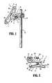
- FIG. 1is a perspective view of an occipital fixation assembly with a surgical rod secured thereon according to an embodiment of the present disclosure
- FIG. 2is a front view of the occipital fixation assembly depicted in FIG. 1 ;
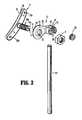
- FIG. 3is an exploded view of the occipital fixation assembly depicted in FIG. 1 with components separated;
- FIG. 4is an exploded view of a coupling member associated with the occipital fixation assembly depicted in FIG. 1 ;
- FIG. 5is a perspective view of an alternative configuration of the occipital fixation assembly depicted in FIG. 1 ;
- FIG. 6is a front view of the occipital fixation assembly depicted in FIG. 5 ;
- FIGS. 7A-7Care perspective views illustrating a mounting plate of the occipital fixation assembly depicted in FIG. 5 with the mounting plate shown in various configurations;
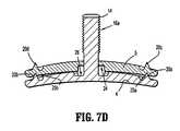
- FIG. 7Dis a cross-sectional view of the mounting plate depicted in the configuration of FIG. 7A taken along section line 7 D- 7 D;
- FIG. 8Ais a perspective view of an alternative embodiment of a threaded post that may be utilized with the occipital fixation assembly depicted in FIG. 1 ;
- FIG. 8Bis a side view of the threaded post depicted in FIG. 8A ;
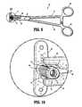
- FIG. 9is a perspective view of a surgical instrument grasping the threaded post depicted in FIG. 8A ;
- FIG. 10is an enlarged area of detail depicted in FIG. 9 ;
- FIGS. 11A-11Dare perspective views illustrating an occipital fixation system and method for attaching the occipital fixation assembly to a patient for subsequent attachment of a surgical rod thereto;
- FIG. 12Ais a cross-sectional view of a coupling member according to another embodiment of the present disclosure.
- FIG. 12Bis the enlarged area of detail depicted in FIG. 12A ;
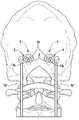
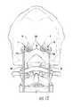
- FIG. 13is a rear view of the occipital fixation assembly depicted in FIG. 1 with the mounting plate shown being inserted within an occipital sinus cavity of a patient.
- proximalrefers to a portion of a surgical instrument closer to the operator while the term “distal” refers to a portion of a surgical instrument farther from the operator.
- distalrefers to a portion of a surgical instrument farther from the operator.
- cephaladis used in this application to indicate a direction toward a patient's head, whereas the term “caudad” indicates a direction toward the patient's feet.
- medialindicates a direction toward the middle of the body of the patient, whilst the term “lateral” indicates a direction toward a side of the body of the patient (i.e., away from the middle of the body of the patient).
- anteriorindicates a direction toward the patient's back
- anteriorindicates a direction toward the patient's front
- an occipital fixation assembly 2is illustrated.
- the occipital fixation assembly 2is positionable within a sinus cavity adjacent a rear portion of the skull, lateral to a brain stem region, i.e., adjacent the occiput.
- the occipital fixation assembly 2includes a first mounting plate 4 , a coupling member 6 and a fixation nut 8 .
- Mounting plate 4includes a generally elongated configuration having top and bottom surfaces 10 and 12 , respectively.
- the mounting plate 4includes a slight curvature or concavity “C” (see FIG. 2 for example) that is configured to follow a contour of the occiput of a skull. As can be appreciated, this curvature or concavity facilitates anchoring the mounting plate 4 to the occiput.
- barbs 20 a and 20 bare operably disposed on the top surface 10 of the mounting plate 4 ( FIG. 1 ).
- Barbs 20 a and 20 bare configured to facilitate anchoring the mounting plate 4 into an interior surface of the skull of a patient and to minimize rotation of the mounting plate 4 when the fixation nut 8 is rotated about a threaded post 14 a ( FIGS. 1-5 ) or movement of the mounting plate 4 when installed in the occiput.
- the barbs 20 a and 20 binclude a generally conical configuration with a substantially pointed tip.
- the barbs 20 a and 20 bmay reside in generally circumferential recesses 21 a and 21 b , respectively, see FIGS. 5-7C .
- the recesses 21 a and 21 bare configured to engage soft tissue that may be disposed adjacent the interior surface of the skull.
- the barbs 20 a and 20 bare set into the recesses 21 a and 21 b at a depth that allows a majority of a surface area of the barbs 20 a and 20 b to sufficiently anchor into the interior surface of the skull.
- the elongated post 14 aextends in a generally orthogonal orientation from the top surface 10 such that the mounting plate 4 has a generally “T” shape ( FIG. 3 ).
- the elongated post 14 amay be monolithically formed with the mounting plate 4 or may be coupled to the mounting plate 4 by one or more suitable coupling methods, e.g., welded to the top surface 10 of the mounting plate 4 .
- the elongated post 14 ais monolithically formed with the mounting plate 4 .
- a plurality of threads 16 aextends along an outer circumferential surface of the elongated post 14 a .
- the plurality of threads 16 aextends along a majority of a length of the elongated post such that a portion of the elongated post 14 a adjacent the top surface 10 of the mounting plate 4 is devoid of the plurality of threads 16 a ( FIGS. 2 and 3 ).
- This portion of the elongated post devoid of the plurality of threads 16 aserves as a relief for cutting the plurality of threads 16 a .
- this portion of the elongated post 16 a devoid of the plurality of threadsallows a mounting plate 5 to be threaded over the threaded post 16 a until the mounting plate 5 passes the plurality of threads 16 a where it can be rotated 360° (see FIG. 7A in combination with FIG. 7B ) without advancing in or out of the occiput when being deployed into a final position ( FIG. 7C ), described in greater detail below.
- this portion of the elongated post devoid of the plurality of threadsis intended to prevent “over-tightening” of the coupling member 6 to the elongated post 14 a.
- a proximal end of the threaded post 14 aincludes a slot 17 ( FIGS. 1 and 3 ) that is configured to receive a working end of a driving device, e.g., a screwdriver (or the like), that is configured to rotate the mounting plate 4 with respect to the fixation nut 8 when the fixation nut 8 is positioned on the threaded post 14 a .
- the driving toolmay include a blade configured for receipt in the slot 17 for holding the mounting plate 4 in a desired orientation while the fixation nut 8 is rotated about the threaded post 14 a.
- the slot 17turns the threaded post 14 a (and, thus, the mounting plate 4 ) after the mounting plate 5 is pulled and set to the inside surface of the occiput (with barbs 20 c and 20 d ) to the final deployed cross position ( FIG. 7C ), described in greater detail below.
- Coupling member 6is configured to operably couple to the mounting plate 4 (or, in some instances, to mounting plate 4 and a second mounting plate 5 , see FIGS. 5-7C ) and to engage an exterior surface of a skull.
- coupling member 6includes a base member 36 .
- Base 36includes a generally annular configuration defined by an outer peripheral wall 35 that joins respective bottom and top surfaces 31 and 33 ( FIGS. 1-4 ) to each other.
- Bottom surface 31includes one or more barbs, e.g., three barbs 20 e - 20 g , disposed thereon (see FIG. 2 in combination with FIG. 4 ) that are configured in a manner as described above with respect to barbs 20 a - 20 b .
- barbs 20 e - 20 gare configured to anchor to an exterior surface of the skull.
- Top surface 33is configured to support the fixation nut 8 thereon.
- An aperture 32FIGS.
- 3 and 4extends from the top surface 33 to the bottom surface 31 and is configured to receive the threaded post 14 a (or in certain embodiments, a threaded post 14 b , described in greater detail below) and a portion of the fixation nut 8 therethrough.
- Coupling member 6is also configured to support the surgical rod “R” thereon ( FIG. 1 ). To this end, coupling member 6 includes an offset extension 34 ( FIGS. 1-4 ).
- Offset extension 34is disposed in parallel orientation with respect to the threaded post 14 a (or in some embodiments with respect to the threaded post 14 b ), see FIGS. 1-3 and 5-7 .
- the offset extension 34includes a generally elongated slot 38 ( FIGS. 3 and 4 ) having an intermittent threaded portion 40 ( FIGS. 3 and 4 show one half of the intermittent threaded portion 40 ) configured to receive a set-screw 42 ( FIGS. 1-3 ) therein and a non-threaded portion 44 ( FIGS. 3 and 4 ) configured to receive the surgical rod “R” therein ( FIGS. 1 and 2 ).
- the threaded and non-threaded portions, 40 and 44 , respectively, of the offset extension 34are arranged such that when the surgical rod “R” is secured thereto, the surgical rod “R” is oriented perpendicular to the set-screw 42 ( FIGS. 1 and 2 ).
- Fixation nut 8is shown.
- Fixation nut 8is configured to threadably engage the threaded post 14 a of the mounting plate 4 (or in some instances threaded post 14 b ( FIG. 8A )).
- Fixation nut 8is rotatable about the threaded post 14 a and translatable therealong.
- fixation nut 8is rotatable with respect to the mounting plate 4 and the coupling member 6 such that rotation of the fixation nut 8 in a predetermined direction, e.g., a clockwise direction, brings the mounting plate 4 and the coupling member 6 toward one another and into secured engagement with the skull of a patient.
- a bottom surface 48 of the fixation nut 8includes a generally elongated extension 50 that is configured to extend into an aperture 52 of a washer 54 and the aperture 32 of the base 36 ( FIG. 4 ).
- the extension 50is configured to facilitate positioning the fixation nut 8 about the threaded post 14 a (or threaded post 14 b ) and the washer 54 distributes or “spreads” a load of the fixation nut 8 evenly across the top surface 33 of the base member 36 when the fixation nut is rotated about the threaded post 14 a .
- the washer 56has a generally conical shape and is also intended to serve as a lock washer. While the fixation nut 8 and washer 56 have been described herein as two separate components that couple to the coupling member 6 , it is within the purview of the present disclosure that the coupling member 6 , fixation nut 8 and washer 56 may be formed as one integral component.
- a second mounting plate 5may be operably coupled to the mounting plate 4 , see FIGS. 5-7C .
- the mounting plate 5includes an opening 23 of suitable dimension, see FIGS. 7A-7C . More particularly, the opening 23 includes an outer diameter that is less than an outer diameter defined by an outer edge of the plurality of threads 16 a .
- the mounting plate 5is rotatable about the threaded post 14 a such that the mounting plate 5 may be rotated from a first position, e.g., a “nested position,” ( FIGS.
- FIGS. 7A and 7Dthat is conducive for positioning the mounting plates 4 and 5 adjacent to an interior surface of a skull, to a subsequent or anchoring position ( FIGS. 7B-7C ) that is conducive for securing or lagging the mounting plates 4 and 5 to the interior surface of a skull.
- the mounting plates 4 and 5may be disposed transverse to each other and form a generally crisscross or “X” shape or configuration, as best seen in FIG. 7C .
- Mounting plate 5includes one or more barbs, e.g., barbs 20 c and 20 d , disposed on a top surface 30 thereof. As described above with respect to barbs 20 a and 20 b , barbs 20 c and 20 d may reside in corresponding recesses 21 c and 21 d , respectively, see FIGS. 5-7C ).
- a bottom surface 28 of the mounting plate 5includes a pair of indents 25 a and 25 b that are configured to releasably engage the barbs 20 a and 20 b ( FIG. 7D ); the indents 25 a and 25 b are shown engaged with the barbs 20 a and 20 b , respectively and, as a result thereof, are not explicitly shown.
- the mounting plate 5 and the mounting plate 4can be inserted together into an aperture or slot in the occiput and rotated together until a final position, e.g., an anchored position, is achieved for the mounting plate 5 , which can be seated or anchored into the occiput by pulling the nested mounting plates 4 and 5 so that the barbs 20 c and 20 d on the mounting plate 5 “dig” into the inside of the occiput. Subsequently, the mounting plate 4 can be deployed to the final (cross) position ( FIG. 7C ) using the slot 17 in the end of the threaded bolt.
- the operable end of a screwdrivermay be utilized to engage the slot 17 and, subsequently, turn the mounting plate 4 that disengages the barbs 20 a and 20 b from the respective indents 25 a and 25 b .
- the barbs 20 a and 20 b on the mounting plate 4may then be brought into contact with the inside of the occiput, thus, fixing both mounting plates 4 and 5 in place.
- a bottom surface 28 of the mounting plate 5includes a notched portion 24 that is configured to receive and/or mate with a portion, e.g., a corresponding notched portion 26 disposed on the top surface 10 , of the mounting plate 4 ( FIGS. 7B and 7D ).
- the notched portions 24 and 26enable the top surface 10 of the mounting plate and top surface 30 of the mounting plate 5 to be flush with each other, as best seen in FIG. 7D ; this provides a substantially uniform contact surface between the mounting plates 4 and 5 and the interior surface of the skull.
- This substantially uniform contact surfacefacilitates positioning the barbs 20 a - 20 d adjacent to the interior surface of the skull, which, in turn, ensures that the barbs 20 a - 20 d properly engage the interior surface of skull.
- having all the barbs 20 a - 20 d properly engaged to the interior surface of the skullreduces and/or eliminates the likelihood of inadvertent movement of the mounting plates 4 and 5 after the occipital fixation assembly 2 a has been affixed to the interior surface of the skull.
- an apertureis, initially, created within a sinus cavity adjacent a rear portion of a skull of a patient, i.e., adjacent the occiput.
- the aperturemay be created utilizing one or more suitable surgical devices, e.g., a surgical drill.
- Mounting plate 4is positioned through the aperture created within the sinus cavity adjacent the occiput. Thereafter, coupling member 6 is positioned about the threaded post 14 a (see FIG. 1 in combination with FIG. 3 ).
- one end of the mounting plate 4is inserted through the opening until the opposing end clears the surface of the skull and can be positioned beneath the surface of the skull. Subsequently, the mounting plate 4 is moved in a generally opposing direction such that the entire mounting plate 4 is disposed beneath the surface of the skull (i.e. on the inside).
- the threaded post 14 aextends through the opening.
- This installation techniqueis applicable to all disclosed embodiments of the occipital fixation assembly. As will be appreciated, the opening will have a dimension that is slightly greater than the dimensions of the mounting plate 4 .
- the fixation nut 8 including the washer 54is positioned about the threaded post 14 a and over the base 36 of coupling member 6 .
- the fixation nut 8 including washer 54is shown engaged with the coupling member 6 .
- the fixation nut 8is rotated in a predetermined direction, e.g., a clockwise direction, about the threaded post 14 a .
- a screwdriveror other suitable device is utilized to engage the slot 17 to facilitate rotation the mounting plate 4 and/or fixation nut 8 .
- Rotation of the fixation nut 8 about the threaded post 14 bcauses the coupling member 6 and the mounting plate 4 to move toward one another and into secured engagement with an interior and exterior surface, respectively, of the skull of a patient.
- the occiputis “sandwiched” between the surgical rod coupling member 6 (with barbs 20 e - 20 g ) and mounting plate 4 (with barbs 20 a - 20 b ) by threading the fixation nut 8 over the threaded post 14 a and tightening to the specified torque.
- the occiputis “sandwiched” between the surgical rod coupling member 6 (with barbs 20 e - 20 g ) and mounting plates 4 and 5 (with barbs 20 a - 20 d ) by threading the fixation nut 8 over the threaded post 14 a and tightening to the specified torque.
- the surgical rod “R”is coupled to the offset extension 34 of the coupling member 6 and secured to the coupling member 6 via the set screw 42 .
- the combination of the unique mounting plate 4 having the threaded post 14 a configured to couple to the coupling member 6reduces and/or eliminates the likelihood of the occipital fixation assembly 2 inadvertently pulling out from the occiput, which, in turn, reduces the risk for cerebellar injury.
- anchoring the barbs 20 a - 20 b and the barbs 20 e - 20 g into the interior and exterior surfaces, respectively, of the skulldiminishes the likelihood of inadvertent rotation of mounting plate 4 and coupling member 6 after the surgical rod “R” has been attached to the occipital fixation assembly and/or the spine.
- an alternate embodiment of an elongated postis designated elongated post 14 b .
- the elongated post 14 bis provided without the slot 17 .
- elongated post 14 bincludes a plurality of non-continuous threads 16 b extending partially along an outer circumferential surface of the elongated post 14 b .
- a proximal end of the elongated post 14 bincludes a threaded aperture 19 that extends into the threaded post 14 b ( FIG. 8A ).
- the threaded aperture 19is configured to receive one end of a surgical device, e.g., wrench assembly 80 , for positioning and turning the fixation nut 8 about the threaded post 14 b ( FIGS. 11A-11D ).
- a non-threaded aperture 21extends traverse to the threaded aperture 19 and is configured to receive one end of a surgical device, e.g., a forceps 60 , for grasping the threaded post 14 b and maintaining the mounting plate 4 a in a non-rotatable state when the fixation nut 8 is rotated about the elongated post 14 b ( FIGS. 9-11B ).
- system 100includes a forceps 60 ( FIGS. 9 and 11A-11C ), a wrench assembly 80 ( FIGS. 11A-11D ) and the occipital fixation assembly 2 b ( FIG. 11D ) that includes the mounting plate 4 a with the threaded post 14 b ( FIG. 10 ).
- Forceps 60is configured to grasp a portion of the threaded post 14 b (as best seen in FIG. 10 ). More particularly, the forceps 60 may be utilized to grasp the threaded post 14 b to facilitate positioning the mounting plate 4 within the aperture created within the sinus cavity adjacent a rear portion of a skull of a patient, i.e., the occiput. Moreover, and as noted above, forceps 60 may be utilized to grasp the threaded post 14 b to maintain the mounting plate 4 a in a non-rotatable state when the fixation nut 8 is rotated about the elongated post 14 b . Forceps 60 includes first and second shafts 61 and 62 .
- Each shaft 61 and 62has a respective jaw member 63 and 64 extending from a distal end thereof and a handle 65 and 66 disposed at a proximal end thereof for effecting movement of the jaw members 63 and 64 relative to one another about a pivot 67 .
- the jaw members 63 and 64are movable from a first position ( FIG. 11C ) wherein the jaw members 63 and 64 are disposed in spaced relation relative to one another to a second position wherein the jaw members 63 and 64 cooperate to grasp the threaded post ( FIGS. 9-11B ).
- Each of the jaw members 63 and 64includes a respective inner facing surface 69 and 68 ( FIGS. 10 and 11C ) having a respective proximal end 70 and 71 ( FIG. 9 ) and a respective distal end 72 and 73 that is offset from the proximal end 70 and 71 ( FIG. 10 ).
- the distal ends 72 and 73 of the inner facing surfaces 69 and 68remain spaced-apart from each other to facilitate grasping the threaded post therebetween ( FIGS. 9-11A ).
- the distal ends 72 and 73 of the jaw members 63 and 64include a protrusion 74 and 75 ( FIGS. 10 and 11C ) thereon that is configured to releasably engage the non-threaded aperture 21 on the threaded post 14 b.
- a ratchet mechanism 90may be operably coupled to the shafts 61 and 62 adjacent the handles 65 and 66 and is configured to maintain the jaw members 63 and 64 in one or more positions. More particularly, each shaft 61 and 62 includes a respective ratchet component 90 a and 90 b each having a plurality of ratchet teeth that are configured to matingly engage with one another.
- the inner facing surfaces 69 and 68 of the forceps 60may be provided without the protrusions 74 and 75 .
- the inner facing surfaces 69 and 68 of forceps 60may include one or more slots or grooves that are configured to matingly engage with the plurality of threads 16 a on the threaded post 14 a.
- Wrench assembly 80is configured to rotate the fixation nut 8 about the threaded post 14 b ( FIGS. 11B and 11C ).
- Wrench assembly 80includes a coupling member 81 that is configured to threadably engage the threaded aperture 19 on the threaded post 14 b of the mounting plate 4 ( FIGS. 11A-11C ).
- Wrench assembly 80includes a wrench head member 82 that is selectively and coaxially engageable with the coupling member 81 ( FIGS. 11A-11C ).
- the coupling member 81includes a generally elongated shaft 83 ( FIGS. 11A and 11D ) having a threaded distal end 84 ( FIGS. 11A and 11C ), and proximal end 85 that is configured to rotate the threaded distal end 84 into the threaded aperture 19 of the threaded post 14 b of the mounting plate 4 a for securement of the coupling member to the mounting plate 4 .
- a portion 86 ( FIGS. 11A and 11D ) of the coupling member 81 proximate to the threaded distal end 84has an outer diameter that is slightly smaller than an inner diameter of the fixation nut 8 , so that the fixation nut 8 can slide over portion 86 .
- the portion 86is configured to facilitate positioning the fixation nut 8 on the threaded post 14 b of the mounting plate 4 a. More particularly, the portion 86 is configured to guide the fixation nut 8 into position on the threaded post 14 b .
- the elongated extension 50 of the fixation nut 8is configured to slide over the portion 86 and guide the fixation nut 8 into position on the threaded post 14 b
- the proximal end 85 of the coupling member 81is complementary shaped to receive an open end of a turn-key 87 .
- the proximal end 85 and the open end of the turn-key 87include a hexagonal shape.
- the turn-key 87is configured to facilitate rotation of the threaded distal end 84 into the threaded aperture 19 on the threaded post 14 b of the mounting plate 4 a.
- a portion 88 of the shaft 81 proximate to the threaded distal end 84is textured or otherwise treated to provide an additional gripping surface for a user, or to provide mechanical interface for maintaining the turn-key 87 at the proximal end 85 .
- the wrench head member 82is configured to releasably engage the fixation nut 8 and rotate the fixation nut 8 about the threaded post 14 b of the mounting plate 4 a .
- the wrench head member 82is complementary shaped to receive and turn the fixation nut 8 .
- a proximal end 89 of the wrench head member 82is textured or otherwise treated to facilitate rotation of the wrench member head.
- the wrench head member 82may be utilized to rotate the fixation nut 8 about the threaded post 14 a.
- An apertureis created within a sinus cavity adjacent a rear portion of a skull of a patient.
- the aperturemay be created utilizing one or more suitable surgical devices, e.g., a surgical drill.
- the forceps 60may be utilized for grasping the threaded post 14 b to insert the mounting plate 4 a through the aperture created within the sinus cavity and to temporarily hold the threaded post 14 b in place ( FIGS. 9-11B ). Thereafter, coupling member 6 is positioned about the threaded post 14 b.
- the fixation nut 8 including the washer 54is positioned about the threaded post 14 b and over the base 36 of coupling member 6 .
- the coupling member 81 of the wrench assembly 80may be coupled to the threaded post 14 b , see FIG. 11A where the coupling member 81 is shown adjacent the threaded post 14 b just before coupling the coupling member 81 to the threaded post 14 b .
- the turn-keymay be utilized to facilitate turning the coupling member 81 about the threaded post 14 b.
- the fixation nut 8is rotated in a predetermined direction, e.g., a clockwise direction, about the threaded post 14 b .
- a predetermined directione.g., a clockwise direction
- the wrench head member 82may be positioned coaxially about the coupling member 81 and into engagement with the fixation nut 8 ( FIG. 11B ). It should be noted that once the fixation nut 8 has been engaged to the threaded post 14 b , the forceps 60 may be removed from engagement with the threaded post 14 b ( FIG. 11C ).
- the threaded engagement between to threaded distal end 84 and the threaded aperture 19may be opposed to the threaded engagement between fixation nut 8 and post 14 b (i.e., one may engage in a clockwise direction and the other in a counterclockwise direction) so that as the fixation nut 8 is tightened the coupling member 81 does not loosen from the threaded post 14 b . In this manner, even after the forceps 60 have been removed, control may be exerted over the threaded post 14 b as the fixation nut 8 is tightened.
- the wrench head member 82is rotated about the fixation nut 8 , which, in turn, rotates the fixation nut 8 about the threaded post 14 b , this in turn, causes the coupling member 6 and the mounting plate 4 a to move toward one another and into secured engagement with an interior and exterior surface, respectively, of the skull of a patient.
- the wrench assembly 80is removed from the occipital fixation assembly 2 ( FIG. 11D ). Thereafter, the surgical rod “R” is coupled to the offset extension 34 of the coupling member 6 and secured to the coupling member 6 via the set screw 42 .
- the slot 38 of the offset extension 34includes a taper locking mechanism for capturing the surgical rod “R” such that a set screw 42 is not required.
- the slot 38 of the offset extension 34includes a polyaxial coupling for capturing the surgical rod “R” such that an angle and trajectory of the surgical rod “R” does not limit the position of the occipital fixation assembly 2 .
- a fixation nutmay be integrally formed with a coupling member. More particularly, and with reference to FIGS. 12A and 12B , a coupling member 6 A and a fixation nut 8 A are integrally formed with one another via one or more suitable coupling methods, e.g., soldering, brazing or welding. In this instance, the fixation nut 8 A is swaged, but rotatable, to the coupling member 8 A along with a washer making it an integral assembly. In this instance, the coupling member 6 A including the fixation nut 8 A are positioned about the threaded post 14 b simultaneously.
- suitable coupling methodse.g., soldering, brazing or welding.
- the fixation nut 8 Ais swaged, but rotatable, to the coupling member 8 A along with a washer making it an integral assembly.
- the coupling member 6 A including the fixation nut 8 Aare positioned about the threaded post 14 b simultaneously.
Landscapes
- Health & Medical Sciences (AREA)
- Orthopedic Medicine & Surgery (AREA)
- Surgery (AREA)
- Life Sciences & Earth Sciences (AREA)
- Neurology (AREA)
- Medical Informatics (AREA)
- Biomedical Technology (AREA)
- Heart & Thoracic Surgery (AREA)
- Engineering & Computer Science (AREA)
- Molecular Biology (AREA)
- Animal Behavior & Ethology (AREA)
- General Health & Medical Sciences (AREA)
- Public Health (AREA)
- Veterinary Medicine (AREA)
- Nuclear Medicine, Radiotherapy & Molecular Imaging (AREA)
- Neurosurgery (AREA)
- Ophthalmology & Optometry (AREA)
- Surgical Instruments (AREA)
Abstract
Description
Claims (14)
Priority Applications (3)
| Application Number | Priority Date | Filing Date | Title |
|---|---|---|---|
| US14/288,903US9597122B2 (en) | 2009-10-14 | 2014-05-28 | Occipital fixation assembly, system and method for attaching the same |
| US15/453,153US10368920B2 (en) | 2009-10-14 | 2017-03-08 | Occipital fixation assembly, system and method for attaching the same |
| US16/446,136US11272962B2 (en) | 2009-10-14 | 2019-06-19 | Occipital fixation assembly, system and method for attaching the same |
Applications Claiming Priority (3)
| Application Number | Priority Date | Filing Date | Title |
|---|---|---|---|
| US27892509P | 2009-10-14 | 2009-10-14 | |
| US12/904,613US20110087292A1 (en) | 2009-10-14 | 2010-10-14 | Occipital fixation assembly, system and method for attaching the same |
| US14/288,903US9597122B2 (en) | 2009-10-14 | 2014-05-28 | Occipital fixation assembly, system and method for attaching the same |
Related Parent Applications (1)
| Application Number | Title | Priority Date | Filing Date |
|---|---|---|---|
| US12/904,613DivisionUS20110087292A1 (en) | 2009-10-14 | 2010-10-14 | Occipital fixation assembly, system and method for attaching the same |
Related Child Applications (1)
| Application Number | Title | Priority Date | Filing Date |
|---|---|---|---|
| US15/453,153DivisionUS10368920B2 (en) | 2009-10-14 | 2017-03-08 | Occipital fixation assembly, system and method for attaching the same |
Publications (2)
| Publication Number | Publication Date |
|---|---|
| US20140324105A1 US20140324105A1 (en) | 2014-10-30 |
| US9597122B2true US9597122B2 (en) | 2017-03-21 |
Family
ID=43855443
Family Applications (4)
| Application Number | Title | Priority Date | Filing Date |
|---|---|---|---|
| US12/904,613AbandonedUS20110087292A1 (en) | 2009-10-14 | 2010-10-14 | Occipital fixation assembly, system and method for attaching the same |
| US14/288,903Active2031-04-20US9597122B2 (en) | 2009-10-14 | 2014-05-28 | Occipital fixation assembly, system and method for attaching the same |
| US15/453,153Active2030-11-20US10368920B2 (en) | 2009-10-14 | 2017-03-08 | Occipital fixation assembly, system and method for attaching the same |
| US16/446,136Active2031-03-19US11272962B2 (en) | 2009-10-14 | 2019-06-19 | Occipital fixation assembly, system and method for attaching the same |
Family Applications Before (1)
| Application Number | Title | Priority Date | Filing Date |
|---|---|---|---|
| US12/904,613AbandonedUS20110087292A1 (en) | 2009-10-14 | 2010-10-14 | Occipital fixation assembly, system and method for attaching the same |
Family Applications After (2)
| Application Number | Title | Priority Date | Filing Date |
|---|---|---|---|
| US15/453,153Active2030-11-20US10368920B2 (en) | 2009-10-14 | 2017-03-08 | Occipital fixation assembly, system and method for attaching the same |
| US16/446,136Active2031-03-19US11272962B2 (en) | 2009-10-14 | 2019-06-19 | Occipital fixation assembly, system and method for attaching the same |
Country Status (1)
| Country | Link |
|---|---|
| US (4) | US20110087292A1 (en) |
Cited By (2)
| Publication number | Priority date | Publication date | Assignee | Title |
|---|---|---|---|---|
| US20170079691A1 (en)* | 2010-04-08 | 2017-03-23 | Globus Medical, Inc. | Jointed rod |
| US10368920B2 (en) | 2009-10-14 | 2019-08-06 | K2M, Inc. | Occipital fixation assembly, system and method for attaching the same |
Families Citing this family (6)
| Publication number | Priority date | Publication date | Assignee | Title |
|---|---|---|---|---|
| US9451990B2 (en)* | 2004-02-17 | 2016-09-27 | Globus Medical, Inc. | Facet joint replacement instruments and methods |
| CN102488549B (en)* | 2011-11-28 | 2014-07-30 | 北京纳通科技集团有限公司 | Split type occipital plate |
| ITUB20155792A1 (en)* | 2015-11-20 | 2017-05-20 | Medacta Int Sa | OCCIPITAL PLATE FOR STATIONARY-CERVICAL FIXING AND SYSTEM FOR STATIONARY-CERVICAL FIXING |
| CN109009380B (en)* | 2018-06-26 | 2021-03-02 | 黄振强 | Spine posterior multi-point fixing device |
| CA3116344A1 (en) | 2018-10-31 | 2020-05-07 | Dignity Health | Systems and methods for fixating, fusing and/or realigning the sacroiliac joint |
| US11559341B2 (en)* | 2020-02-25 | 2023-01-24 | Aesculap Ag | Surgical instrumentation for cervical-occipito fixation |
Citations (45)
| Publication number | Priority date | Publication date | Assignee | Title |
|---|---|---|---|---|
| US1390485A (en) | 1920-01-28 | 1921-09-13 | William L Bell | Bolt |
| US3019887A (en) | 1959-11-06 | 1962-02-06 | Lowden George | Securing bolt |
| US3997138A (en) | 1974-06-18 | 1976-12-14 | Henry Vernon Crock | Securing devices and structures |
| US4648388A (en) | 1985-11-01 | 1987-03-10 | Acromed Corporation | Apparatus and method for maintaining vertebrae in a desired relationship |
| US4743260A (en) | 1985-06-10 | 1988-05-10 | Burton Charles V | Method for a flexible stabilization system for a vertebral column |
| US5024213A (en) | 1989-02-08 | 1991-06-18 | Acromed Corporation | Connector for a corrective device |
| US5098433A (en) | 1989-04-12 | 1992-03-24 | Yosef Freedland | Winged compression bolt orthopedic fastener |
| US5127912A (en) | 1990-10-05 | 1992-07-07 | R. Charles Ray | Sacral implant system |
| US5129899A (en) | 1991-03-27 | 1992-07-14 | Smith & Nephew Richards Inc. | Bone fixation apparatus |
| US5167665A (en) | 1991-12-31 | 1992-12-01 | Mckinney William W | Method of attaching objects to bone |
| US5234432A (en)* | 1992-03-13 | 1993-08-10 | Brown Byron L | Method and apparatus for definitive cutting of a femur |
| US5250049A (en) | 1992-01-10 | 1993-10-05 | Michael Roger H | Bone and tissue connectors |
| US5257994A (en) | 1991-09-23 | 1993-11-02 | Lin Chih I | Vertebral locking and retrieving system |
| US5269784A (en) | 1991-12-10 | 1993-12-14 | Synthes (U.S.A.) | Screw nut for plate osteosynthesis |
| US5312404A (en) | 1990-07-24 | 1994-05-17 | Acromed Corporation | Spinal column retaining apparatus |
| US5380325A (en) | 1992-11-06 | 1995-01-10 | Biomat | Osteosynthesis device for spinal consolidation |
| WO1995005782A1 (en) | 1993-08-27 | 1995-03-02 | Robin Peter Brown | Apparatus and method for surgically securing bone parts |
| US5507745A (en) | 1994-02-18 | 1996-04-16 | Sofamor, S.N.C. | Occipito-cervical osteosynthesis instrumentation |
| US5545228A (en) | 1991-08-15 | 1996-08-13 | Smith & Nephew Richards Inc. | Offset bone bolt |
| US5545164A (en) | 1992-12-28 | 1996-08-13 | Advanced Spine Fixation Systems, Incorporated | Occipital clamp assembly for cervical spine rod fixation |
| US5591166A (en) | 1995-03-27 | 1997-01-07 | Smith & Nephew Richards, Inc. | Multi angle bone bolt |
| US5649926A (en) | 1994-07-14 | 1997-07-22 | Advanced Spine Fixation Systems, Inc. | Spinal segmental reduction derotational fixation system |
| US5653708A (en) | 1992-12-28 | 1997-08-05 | Advanced Spine Fixation Systems, Inc. | Cervical spine rod fixation system |
| US5713898A (en) | 1993-05-18 | 1998-02-03 | Schafer Micomed Gmbh | Orthopedic surgical holding device |
| US5947968A (en)* | 1997-11-03 | 1999-09-07 | Rogozinski; Chaim | Graft anchor and method |
| US6039738A (en) | 1997-07-03 | 2000-03-21 | Depuy Orthopaedics, Inc. | Fastener |
| US6059786A (en) | 1998-10-22 | 2000-05-09 | Jackson; Roger P. | Set screw for medical implants |
| US6083224A (en) | 1995-01-25 | 2000-07-04 | Sdgi Holdings, Inc. | Dynamic spinal screw-rod connectors |
| US6146384A (en) | 1995-10-13 | 2000-11-14 | Sdgi Holdings, Inc. | Orthopedic fixation device and method of implantation |
| US20010011173A1 (en) | 1996-02-03 | 2001-08-02 | Karl-Dieter Lerch | Device for postoperative fixation back into the cranium of a plug of bone removed therefrom during a surgical operation |
| US6287308B1 (en) | 1997-07-14 | 2001-09-11 | Sdgi Holdings, Inc. | Methods and apparatus for fusionless treatment of spinal deformities |
| US6682532B2 (en) | 2002-03-22 | 2004-01-27 | Depuy Acromed, Inc. | Coupling system and method for extending spinal instrumentation |
| US6755834B2 (en) | 2000-09-15 | 2004-06-29 | Medtronic, Inc. | Cranial flap fixation device |
| US20040127908A1 (en) | 2001-09-25 | 2004-07-01 | Roman Shawn David | Cranial clamp with torque-limiting feature |
| US20050070899A1 (en) | 2003-09-26 | 2005-03-31 | Doubler Robert L. | Polyaxial bone screw with torqueless fastening |
| US20050080417A1 (en)* | 2003-10-14 | 2005-04-14 | Eurosurgical Sa | Occipital fixation device |
| US20050137594A1 (en) | 2002-02-04 | 2005-06-23 | Doubler Robert L. | Spinal fixation assembly |
| US20050256510A1 (en)* | 2004-04-28 | 2005-11-17 | Medtronic, Inc. | Ventriculo-sinus shunting for disease treatment |
| US7048737B2 (en) | 2002-06-11 | 2006-05-23 | Bioplate, Inc. | Cranial bone flap fixation system and method |
| US20060247628A1 (en) | 2005-04-29 | 2006-11-02 | Sdgi Holdings, Inc. | Spinal stabilization apparatus and method |
| US20060264932A1 (en)* | 2005-05-06 | 2006-11-23 | Bert Jeffrey K | Attachment to bone |
| US7303563B2 (en) | 2004-06-17 | 2007-12-04 | Sdgi Holdings, Inc. | Orthopedic fixation system and method of use |
| US20080281359A1 (en) | 2007-01-29 | 2008-11-13 | Abdou M S | Spinal stabilization systems and methods of use |
| US20090030463A1 (en)* | 2007-07-09 | 2009-01-29 | Alphatec Spine, Inc. | Occipital fixation screw |
| US9327069B2 (en)* | 2004-12-21 | 2016-05-03 | Boston Scientific Neuromodulation Corporation | Methods and systems for treating a medical condition by promoting neural remodeling within the brain |
Family Cites Families (7)
| Publication number | Priority date | Publication date | Assignee | Title |
|---|---|---|---|---|
| DE10128917C1 (en)* | 2001-06-15 | 2002-10-24 | Aesculap Ag & Co Kg | Surgical implant for fixing bone plates for repair of broken bone has two discs with crenellated edges, interengaging toothed projections and holes for fastening cord |
| US6050997A (en)* | 1999-01-25 | 2000-04-18 | Mullane; Thomas S. | Spinal fixation system |
| US7850719B2 (en)* | 2004-05-26 | 2010-12-14 | Warsaw Orthopedic, Inc. | Spinal implant apparatus |
| EP1758511A4 (en)* | 2004-06-14 | 2008-12-03 | M S Abdou | Occipital fixation system and method of use |
| US8979903B2 (en)* | 2006-04-26 | 2015-03-17 | Warsaw Orthopedic, Inc. | Revision fixation plate and method of use |
| US20110087292A1 (en) | 2009-10-14 | 2011-04-14 | K2M, Inc. | Occipital fixation assembly, system and method for attaching the same |
| US10548637B2 (en)* | 2011-10-03 | 2020-02-04 | Blockhead Of Chicago, Llc | Implantable bone support systems |
- 2010
- 2010-10-14USUS12/904,613patent/US20110087292A1/ennot_activeAbandoned
- 2014
- 2014-05-28USUS14/288,903patent/US9597122B2/enactiveActive
- 2017
- 2017-03-08USUS15/453,153patent/US10368920B2/enactiveActive
- 2019
- 2019-06-19USUS16/446,136patent/US11272962B2/enactiveActive
Patent Citations (47)
| Publication number | Priority date | Publication date | Assignee | Title |
|---|---|---|---|---|
| US1390485A (en) | 1920-01-28 | 1921-09-13 | William L Bell | Bolt |
| US3019887A (en) | 1959-11-06 | 1962-02-06 | Lowden George | Securing bolt |
| US3997138A (en) | 1974-06-18 | 1976-12-14 | Henry Vernon Crock | Securing devices and structures |
| US4743260A (en) | 1985-06-10 | 1988-05-10 | Burton Charles V | Method for a flexible stabilization system for a vertebral column |
| US4648388A (en) | 1985-11-01 | 1987-03-10 | Acromed Corporation | Apparatus and method for maintaining vertebrae in a desired relationship |
| US4648388B1 (en) | 1985-11-01 | 1995-10-31 | Acromed Corp | Apparatus and method for maintaining vertebrae in a desired relationship |
| US5024213A (en) | 1989-02-08 | 1991-06-18 | Acromed Corporation | Connector for a corrective device |
| US5098433A (en) | 1989-04-12 | 1992-03-24 | Yosef Freedland | Winged compression bolt orthopedic fastener |
| US5312404A (en) | 1990-07-24 | 1994-05-17 | Acromed Corporation | Spinal column retaining apparatus |
| US5127912A (en) | 1990-10-05 | 1992-07-07 | R. Charles Ray | Sacral implant system |
| US5129899A (en) | 1991-03-27 | 1992-07-14 | Smith & Nephew Richards Inc. | Bone fixation apparatus |
| US5545228A (en) | 1991-08-15 | 1996-08-13 | Smith & Nephew Richards Inc. | Offset bone bolt |
| US5257994A (en) | 1991-09-23 | 1993-11-02 | Lin Chih I | Vertebral locking and retrieving system |
| US5269784A (en) | 1991-12-10 | 1993-12-14 | Synthes (U.S.A.) | Screw nut for plate osteosynthesis |
| US5167665A (en) | 1991-12-31 | 1992-12-01 | Mckinney William W | Method of attaching objects to bone |
| US5250049A (en) | 1992-01-10 | 1993-10-05 | Michael Roger H | Bone and tissue connectors |
| US5234432A (en)* | 1992-03-13 | 1993-08-10 | Brown Byron L | Method and apparatus for definitive cutting of a femur |
| US5380325A (en) | 1992-11-06 | 1995-01-10 | Biomat | Osteosynthesis device for spinal consolidation |
| US5545164A (en) | 1992-12-28 | 1996-08-13 | Advanced Spine Fixation Systems, Incorporated | Occipital clamp assembly for cervical spine rod fixation |
| US5653708A (en) | 1992-12-28 | 1997-08-05 | Advanced Spine Fixation Systems, Inc. | Cervical spine rod fixation system |
| US5713898A (en) | 1993-05-18 | 1998-02-03 | Schafer Micomed Gmbh | Orthopedic surgical holding device |
| WO1995005782A1 (en) | 1993-08-27 | 1995-03-02 | Robin Peter Brown | Apparatus and method for surgically securing bone parts |
| US5722976A (en) | 1993-08-27 | 1998-03-03 | Brown; Robin Peter | Apparatus and method for surgically securing bone parts |
| US5507745A (en) | 1994-02-18 | 1996-04-16 | Sofamor, S.N.C. | Occipito-cervical osteosynthesis instrumentation |
| US5649926A (en) | 1994-07-14 | 1997-07-22 | Advanced Spine Fixation Systems, Inc. | Spinal segmental reduction derotational fixation system |
| US6083224A (en) | 1995-01-25 | 2000-07-04 | Sdgi Holdings, Inc. | Dynamic spinal screw-rod connectors |
| US5591166A (en) | 1995-03-27 | 1997-01-07 | Smith & Nephew Richards, Inc. | Multi angle bone bolt |
| US6146384A (en) | 1995-10-13 | 2000-11-14 | Sdgi Holdings, Inc. | Orthopedic fixation device and method of implantation |
| US20010011173A1 (en) | 1996-02-03 | 2001-08-02 | Karl-Dieter Lerch | Device for postoperative fixation back into the cranium of a plug of bone removed therefrom during a surgical operation |
| US6039738A (en) | 1997-07-03 | 2000-03-21 | Depuy Orthopaedics, Inc. | Fastener |
| US6287308B1 (en) | 1997-07-14 | 2001-09-11 | Sdgi Holdings, Inc. | Methods and apparatus for fusionless treatment of spinal deformities |
| US5947968A (en)* | 1997-11-03 | 1999-09-07 | Rogozinski; Chaim | Graft anchor and method |
| US6059786A (en) | 1998-10-22 | 2000-05-09 | Jackson; Roger P. | Set screw for medical implants |
| US6755834B2 (en) | 2000-09-15 | 2004-06-29 | Medtronic, Inc. | Cranial flap fixation device |
| US20040127908A1 (en) | 2001-09-25 | 2004-07-01 | Roman Shawn David | Cranial clamp with torque-limiting feature |
| US20050137594A1 (en) | 2002-02-04 | 2005-06-23 | Doubler Robert L. | Spinal fixation assembly |
| US6682532B2 (en) | 2002-03-22 | 2004-01-27 | Depuy Acromed, Inc. | Coupling system and method for extending spinal instrumentation |
| US7048737B2 (en) | 2002-06-11 | 2006-05-23 | Bioplate, Inc. | Cranial bone flap fixation system and method |
| US20050070899A1 (en) | 2003-09-26 | 2005-03-31 | Doubler Robert L. | Polyaxial bone screw with torqueless fastening |
| US20050080417A1 (en)* | 2003-10-14 | 2005-04-14 | Eurosurgical Sa | Occipital fixation device |
| US20050256510A1 (en)* | 2004-04-28 | 2005-11-17 | Medtronic, Inc. | Ventriculo-sinus shunting for disease treatment |
| US7303563B2 (en) | 2004-06-17 | 2007-12-04 | Sdgi Holdings, Inc. | Orthopedic fixation system and method of use |
| US9327069B2 (en)* | 2004-12-21 | 2016-05-03 | Boston Scientific Neuromodulation Corporation | Methods and systems for treating a medical condition by promoting neural remodeling within the brain |
| US20060247628A1 (en) | 2005-04-29 | 2006-11-02 | Sdgi Holdings, Inc. | Spinal stabilization apparatus and method |
| US20060264932A1 (en)* | 2005-05-06 | 2006-11-23 | Bert Jeffrey K | Attachment to bone |
| US20080281359A1 (en) | 2007-01-29 | 2008-11-13 | Abdou M S | Spinal stabilization systems and methods of use |
| US20090030463A1 (en)* | 2007-07-09 | 2009-01-29 | Alphatec Spine, Inc. | Occipital fixation screw |
Non-Patent Citations (4)
| Title |
|---|
| Faheem A. Sandhu, MD, PhD. et al. "Occipitocervical Fusion for Rheumatoid Arthritis Using the Inside-Outside Stabilization Technique", vol. 28, No. 4, 2003, pp. 414-419. |
| James Zucherman, MD, et al. "Early Results of Spinal Fusion Using Variable Spine Plating Systems", vol. 13, No. 5, 1988, pp. 570-579. |
| Rolando M. Puno, MD, et al. "Biochemical Analysis of Transpedicular Rod Systems", vol. 16, No. 8, 1991, pp. 973-980. |
| Vijay K. Goel, PhD. et al. "Effects of Rigidity of an Internal Fixation Device", vol. 16, No. 3 Supplemental, 1991, pp. S155-S161. |
Cited By (4)
| Publication number | Priority date | Publication date | Assignee | Title |
|---|---|---|---|---|
| US10368920B2 (en) | 2009-10-14 | 2019-08-06 | K2M, Inc. | Occipital fixation assembly, system and method for attaching the same |
| US11272962B2 (en) | 2009-10-14 | 2022-03-15 | K2M, Inc. | Occipital fixation assembly, system and method for attaching the same |
| US20170079691A1 (en)* | 2010-04-08 | 2017-03-23 | Globus Medical, Inc. | Jointed rod |
| US10617450B2 (en)* | 2010-04-08 | 2020-04-14 | Globus Medical, Inc. | Jointed rod |
Also Published As
| Publication number | Publication date |
|---|---|
| US20170238972A1 (en) | 2017-08-24 |
| US20190343561A1 (en) | 2019-11-14 |
| US20140324105A1 (en) | 2014-10-30 |
| US20110087292A1 (en) | 2011-04-14 |
| US10368920B2 (en) | 2019-08-06 |
| US11272962B2 (en) | 2022-03-15 |
Similar Documents
| Publication | Publication Date | Title |
|---|---|---|
| US11272962B2 (en) | Occipital fixation assembly, system and method for attaching the same | |
| US20200179009A1 (en) | Orthopedic fastener for stabilization and fixation | |
| EP2467076B1 (en) | Transverse rod connector | |
| US8267980B2 (en) | Spinal stabilizing system | |
| JP6074571B2 (en) | Minimally invasive method and apparatus for stabilizing the spinal column | |
| US8454658B2 (en) | Surgical bone anchoring device and spinal column fixation system | |
| US8894695B2 (en) | Occipital plate for cervical fixation | |
| JP6072012B2 (en) | Minimally invasive spinal fixation system including vertebra alignment features | |
| JP3738243B2 (en) | Bone fixation assembly | |
| JP4536118B2 (en) | Spine implant with a wide range of multiaxial fastener assemblies | |
| EP2434973B1 (en) | Surgical instrument for fixing a clamp to a bone fixation device | |
| US8690923B2 (en) | Bone fixation systems and methods | |
| US20080300638A1 (en) | Break-off screw extensions | |
| US20040267275A1 (en) | Spinal implant holder and rod reduction systems and methods | |
| EP1919381B1 (en) | Apparatus for external fixation of the pelvic ring | |
| KR20090007405A (en) | Methods and devices for the interconnection of bone attachment devices | |
| CA2574174A1 (en) | Bone distraction apparatus | |
| US11246629B2 (en) | Transverse connector | |
| JP2007508118A (en) | Spinal fixation hook and spinal fixation method | |
| WO2008036578A2 (en) | Orthopedic plate system |
Legal Events
| Date | Code | Title | Description |
|---|---|---|---|
| AS | Assignment | Owner name:K2M, INC., VIRGINIA Free format text:ASSIGNMENT OF ASSIGNORS INTEREST;ASSIGNORS:SANDHU, FAHEEM;STRAUSS, KEVIN R;MCCLINTOCK, LARRY;SIGNING DATES FROM 20101027 TO 20101106;REEL/FRAME:032976/0930 | |
| AS | Assignment | Owner name:SILICON VALLEY BANK, CALIFORNIA Free format text:FIRST AMENDMENT TO PATENT SECURITY AGREEMENT;ASSIGNORS:K2M, INC.;K2M UNLIMITED;K2M HOLDINGS, INC.;REEL/FRAME:034034/0097 Effective date:20141021 | |
| AS | Assignment | Owner name:SILICON VALLEY BANK, AS ADMINISTRATIVE AGENT, CALIFORNIA Free format text:SECOND AMENDMENT TO PATENT SECURITY AGREEMENT;ASSIGNORS:K2M, INC.;K2M HOLDINGS, INC.;K2M UK LIMITED;REEL/FRAME:037091/0221 Effective date:20151029 Owner name:SILICON VALLEY BANK, AS ADMINISTRATIVE AGENT, CALI Free format text:SECOND AMENDMENT TO PATENT SECURITY AGREEMENT;ASSIGNORS:K2M, INC.;K2M HOLDINGS, INC.;K2M UK LIMITED;REEL/FRAME:037091/0221 Effective date:20151029 | |
| STCF | Information on status: patent grant | Free format text:PATENTED CASE | |
| FEPP | Fee payment procedure | Free format text:ENTITY STATUS SET TO UNDISCOUNTED (ORIGINAL EVENT CODE: BIG.) | |
| AS | Assignment | Owner name:K2M HOLDINGS, INC., VIRGINIA Free format text:RELEASE BY SECURED PARTY;ASSIGNOR:SILICON VALLEY BANK;REEL/FRAME:047496/0001 Effective date:20181109 Owner name:K2M, INC., VIRGINIA Free format text:RELEASE BY SECURED PARTY;ASSIGNOR:SILICON VALLEY BANK;REEL/FRAME:047496/0001 Effective date:20181109 Owner name:K2M UK LIMITED, UNITED KINGDOM Free format text:RELEASE BY SECURED PARTY;ASSIGNOR:SILICON VALLEY BANK;REEL/FRAME:047496/0001 Effective date:20181109 | |
| MAFP | Maintenance fee payment | Free format text:PAYMENT OF MAINTENANCE FEE, 4TH YEAR, LARGE ENTITY (ORIGINAL EVENT CODE: M1551); ENTITY STATUS OF PATENT OWNER: LARGE ENTITY Year of fee payment:4 | |
| MAFP | Maintenance fee payment | Free format text:PAYMENT OF MAINTENANCE FEE, 8TH YEAR, LARGE ENTITY (ORIGINAL EVENT CODE: M1552); ENTITY STATUS OF PATENT OWNER: LARGE ENTITY Year of fee payment:8 | |
| AS | Assignment | Owner name:ANKURA TRUST COMPANY, LLC, AS COLLATERAL AGENT, CONNECTICUT Free format text:PATENT SECURITY AGREEMENT;ASSIGNORS:K2M, INC.;VB SPINE US OPCO LLC;VB SPINE LLC;REEL/FRAME:071682/0116 Effective date:20250616 | |
| AS | Assignment | Owner name:TEXAS CAPITAL BANK, AS COLLATERAL AGENT, TEXAS Free format text:SECURITY INTEREST;ASSIGNORS:K2M, INC.;VB SPINE US OPCO LLC;REEL/FRAME:072340/0397 Effective date:20250401 |