US9597112B2 - Low-profile surgical access devices with anchoring - Google Patents
Low-profile surgical access devices with anchoringDownload PDFInfo
- Publication number
- US9597112B2 US9597112B2US13/388,644US201013388644AUS9597112B2US 9597112 B2US9597112 B2US 9597112B2US 201013388644 AUS201013388644 AUS 201013388644AUS 9597112 B2US9597112 B2US 9597112B2
- Authority
- US
- United States
- Prior art keywords
- housing
- access device
- surgical
- plenum
- surgical access
- Prior art date
- Legal status (The legal status is an assumption and is not a legal conclusion. Google has not performed a legal analysis and makes no representation as to the accuracy of the status listed.)
- Active, expires
Links
Images


Classifications
- A—HUMAN NECESSITIES
- A61—MEDICAL OR VETERINARY SCIENCE; HYGIENE
- A61B—DIAGNOSIS; SURGERY; IDENTIFICATION
- A61B17/00—Surgical instruments, devices or methods
- A61B17/34—Trocars; Puncturing needles
- A61B17/3417—Details of tips or shafts, e.g. grooves, expandable, bendable; Multiple coaxial sliding cannulas, e.g. for dilating
- A—HUMAN NECESSITIES
- A61—MEDICAL OR VETERINARY SCIENCE; HYGIENE
- A61B—DIAGNOSIS; SURGERY; IDENTIFICATION
- A61B17/00—Surgical instruments, devices or methods
- A61B17/34—Trocars; Puncturing needles
- A—HUMAN NECESSITIES
- A61—MEDICAL OR VETERINARY SCIENCE; HYGIENE
- A61B—DIAGNOSIS; SURGERY; IDENTIFICATION
- A61B1/00—Instruments for performing medical examinations of the interior of cavities or tubes of the body by visual or photographical inspection, e.g. endoscopes; Illuminating arrangements therefor
- A61B1/32—Devices for opening or enlarging the visual field, e.g. of a tube of the body
- A—HUMAN NECESSITIES
- A61—MEDICAL OR VETERINARY SCIENCE; HYGIENE
- A61B—DIAGNOSIS; SURGERY; IDENTIFICATION
- A61B17/00—Surgical instruments, devices or methods
- A61B17/02—Surgical instruments, devices or methods for holding wounds open, e.g. retractors; Tractors
- A—HUMAN NECESSITIES
- A61—MEDICAL OR VETERINARY SCIENCE; HYGIENE
- A61B—DIAGNOSIS; SURGERY; IDENTIFICATION
- A61B90/00—Instruments, implements or accessories specially adapted for surgery or diagnosis and not covered by any of the groups A61B1/00 - A61B50/00, e.g. for luxation treatment or for protecting wound edges
- A—HUMAN NECESSITIES
- A61—MEDICAL OR VETERINARY SCIENCE; HYGIENE
- A61M—DEVICES FOR INTRODUCING MEDIA INTO, OR ONTO, THE BODY; DEVICES FOR TRANSDUCING BODY MEDIA OR FOR TAKING MEDIA FROM THE BODY; DEVICES FOR PRODUCING OR ENDING SLEEP OR STUPOR
- A61M29/00—Dilators with or without means for introducing media, e.g. remedies
- A—HUMAN NECESSITIES
- A61—MEDICAL OR VETERINARY SCIENCE; HYGIENE
- A61M—DEVICES FOR INTRODUCING MEDIA INTO, OR ONTO, THE BODY; DEVICES FOR TRANSDUCING BODY MEDIA OR FOR TAKING MEDIA FROM THE BODY; DEVICES FOR PRODUCING OR ENDING SLEEP OR STUPOR
- A61M39/00—Tubes, tube connectors, tube couplings, valves, access sites or the like, specially adapted for medical use
- A61M39/02—Access sites
- A61M39/0247—Semi-permanent or permanent transcutaneous or percutaneous access sites to the inside of the body
- A—HUMAN NECESSITIES
- A61—MEDICAL OR VETERINARY SCIENCE; HYGIENE
- A61M—DEVICES FOR INTRODUCING MEDIA INTO, OR ONTO, THE BODY; DEVICES FOR TRANSDUCING BODY MEDIA OR FOR TAKING MEDIA FROM THE BODY; DEVICES FOR PRODUCING OR ENDING SLEEP OR STUPOR
- A61M39/00—Tubes, tube connectors, tube couplings, valves, access sites or the like, specially adapted for medical use
- A61M39/02—Access sites
- A61M39/04—Access sites having pierceable self-sealing members
- G—PHYSICS
- G02—OPTICS
- G02B—OPTICAL ELEMENTS, SYSTEMS OR APPARATUS
- G02B23/00—Telescopes, e.g. binoculars; Periscopes; Instruments for viewing the inside of hollow bodies; Viewfinders; Optical aiming or sighting devices
- G02B23/24—Instruments or systems for viewing the inside of hollow bodies, e.g. fibrescopes
- A—HUMAN NECESSITIES
- A61—MEDICAL OR VETERINARY SCIENCE; HYGIENE
- A61B—DIAGNOSIS; SURGERY; IDENTIFICATION
- A61B17/00—Surgical instruments, devices or methods
- A61B17/34—Trocars; Puncturing needles
- A61B17/3417—Details of tips or shafts, e.g. grooves, expandable, bendable; Multiple coaxial sliding cannulas, e.g. for dilating
- A61B17/3421—Cannulas
- A61B17/3423—Access ports, e.g. toroid shape introducers for instruments or hands
- A—HUMAN NECESSITIES
- A61—MEDICAL OR VETERINARY SCIENCE; HYGIENE
- A61B—DIAGNOSIS; SURGERY; IDENTIFICATION
- A61B17/00—Surgical instruments, devices or methods
- A61B17/34—Trocars; Puncturing needles
- A61B17/3417—Details of tips or shafts, e.g. grooves, expandable, bendable; Multiple coaxial sliding cannulas, e.g. for dilating
- A61B17/3421—Cannulas
- A61B17/3431—Cannulas being collapsible, e.g. made of thin flexible material
- A—HUMAN NECESSITIES
- A61—MEDICAL OR VETERINARY SCIENCE; HYGIENE
- A61B—DIAGNOSIS; SURGERY; IDENTIFICATION
- A61B17/00—Surgical instruments, devices or methods
- A61B17/34—Trocars; Puncturing needles
- A61B17/3474—Insufflating needles, e.g. Veress needles
- A—HUMAN NECESSITIES
- A61—MEDICAL OR VETERINARY SCIENCE; HYGIENE
- A61B—DIAGNOSIS; SURGERY; IDENTIFICATION
- A61B17/00—Surgical instruments, devices or methods
- A61B17/34—Trocars; Puncturing needles
- A61B17/3498—Valves therefor, e.g. flapper valves, slide valves
- A—HUMAN NECESSITIES
- A61—MEDICAL OR VETERINARY SCIENCE; HYGIENE
- A61B—DIAGNOSIS; SURGERY; IDENTIFICATION
- A61B17/00—Surgical instruments, devices or methods
- A61B17/34—Trocars; Puncturing needles
- A61B17/3417—Details of tips or shafts, e.g. grooves, expandable, bendable; Multiple coaxial sliding cannulas, e.g. for dilating
- A61B17/3421—Cannulas
- A61B2017/3445—Cannulas used as instrument channel for multiple instruments
- A—HUMAN NECESSITIES
- A61—MEDICAL OR VETERINARY SCIENCE; HYGIENE
- A61B—DIAGNOSIS; SURGERY; IDENTIFICATION
- A61B17/00—Surgical instruments, devices or methods
- A61B17/34—Trocars; Puncturing needles
- A61B2017/348—Means for supporting the trocar against the body or retaining the trocar inside the body
- A61B2017/3482—Means for supporting the trocar against the body or retaining the trocar inside the body inside
- A61B2017/3484—Anchoring means, e.g. spreading-out umbrella-like structure
- A—HUMAN NECESSITIES
- A61—MEDICAL OR VETERINARY SCIENCE; HYGIENE
- A61M—DEVICES FOR INTRODUCING MEDIA INTO, OR ONTO, THE BODY; DEVICES FOR TRANSDUCING BODY MEDIA OR FOR TAKING MEDIA FROM THE BODY; DEVICES FOR PRODUCING OR ENDING SLEEP OR STUPOR
- A61M39/00—Tubes, tube connectors, tube couplings, valves, access sites or the like, specially adapted for medical use
- A61M39/02—Access sites
- A61M39/0247—Semi-permanent or permanent transcutaneous or percutaneous access sites to the inside of the body
- A61M2039/0261—Means for anchoring port to the body, or ports having a special shape or being made of a specific material to allow easy implantation/integration in the body
- A—HUMAN NECESSITIES
- A61—MEDICAL OR VETERINARY SCIENCE; HYGIENE
- A61M—DEVICES FOR INTRODUCING MEDIA INTO, OR ONTO, THE BODY; DEVICES FOR TRANSDUCING BODY MEDIA OR FOR TAKING MEDIA FROM THE BODY; DEVICES FOR PRODUCING OR ENDING SLEEP OR STUPOR
- A61M39/00—Tubes, tube connectors, tube couplings, valves, access sites or the like, specially adapted for medical use
- A61M39/02—Access sites
- A61M39/0247—Semi-permanent or permanent transcutaneous or percutaneous access sites to the inside of the body
- A61M2039/0264—Semi-permanent or permanent transcutaneous or percutaneous access sites to the inside of the body with multiple inlets or multiple outlets
- A—HUMAN NECESSITIES
- A61—MEDICAL OR VETERINARY SCIENCE; HYGIENE
- A61M—DEVICES FOR INTRODUCING MEDIA INTO, OR ONTO, THE BODY; DEVICES FOR TRANSDUCING BODY MEDIA OR FOR TAKING MEDIA FROM THE BODY; DEVICES FOR PRODUCING OR ENDING SLEEP OR STUPOR
- A61M39/00—Tubes, tube connectors, tube couplings, valves, access sites or the like, specially adapted for medical use
- A61M39/02—Access sites
- A61M39/0247—Semi-permanent or permanent transcutaneous or percutaneous access sites to the inside of the body
- A61M2039/0276—Semi-permanent or permanent transcutaneous or percutaneous access sites to the inside of the body for introducing or removing fluids into or out of the body
- A—HUMAN NECESSITIES
- A61—MEDICAL OR VETERINARY SCIENCE; HYGIENE
- A61M—DEVICES FOR INTRODUCING MEDIA INTO, OR ONTO, THE BODY; DEVICES FOR TRANSDUCING BODY MEDIA OR FOR TAKING MEDIA FROM THE BODY; DEVICES FOR PRODUCING OR ENDING SLEEP OR STUPOR
- A61M39/00—Tubes, tube connectors, tube couplings, valves, access sites or the like, specially adapted for medical use
- A61M39/02—Access sites
- A61M39/0247—Semi-permanent or permanent transcutaneous or percutaneous access sites to the inside of the body
- A61M2039/0279—Semi-permanent or permanent transcutaneous or percutaneous access sites to the inside of the body for introducing medical instruments into the body, e.g. endoscope, surgical tools
- A—HUMAN NECESSITIES
- A61—MEDICAL OR VETERINARY SCIENCE; HYGIENE
- A61M—DEVICES FOR INTRODUCING MEDIA INTO, OR ONTO, THE BODY; DEVICES FOR TRANSDUCING BODY MEDIA OR FOR TAKING MEDIA FROM THE BODY; DEVICES FOR PRODUCING OR ENDING SLEEP OR STUPOR
- A61M39/00—Tubes, tube connectors, tube couplings, valves, access sites or the like, specially adapted for medical use
- A61M39/02—Access sites
- A61M39/04—Access sites having pierceable self-sealing members
- A61M39/045—Access sites having pierceable self-sealing members pre-slit to be pierced by blunt instrument
Definitions
- the present inventionrelates to surgical access devices for performing minimally-invasive surgical procedures.
- the present inventionis directed to surgical access devices that are particularly adapted to securely anchoring in an incision, such as one made through the abdominal wall of a patient.
- the present inventionis also directed to such surgical access devices that include a non-mechanical pressure barrier for inhibiting loss of peritoneal pressure under abdominal insufflation.
- a variety of access devicesare known in the art for accessing a surgical site, such as the abdominal cavity. Typically, ensuring that such access devices stay securely mounted in the abdominal wall without causing excessive trauma is a primary goal.
- the present inventionprovides various solutions to these problems.
- the inventionincludes, in one aspect, a surgical access device including a housing having proximal and distal end portions, an access tube extending distally from the distal end of the housing, adapted and configured to extend at least partially though an incision formed in the abdominal wall of a patient, the access tube having a hyperbolic shape in cross section, with an expanded-diameter distal portion to inhibit removal from an incision, and a cover disposed over a proximal end portion of the housing adapted and configured to reduce sound from fluid flowing through the access device.
- the covercan include a removable lid.
- the covercan include a sound-absorbing material.
- the covercan include an engagement portion adapted to engage with the housing, and a lid portion attached to the engagement portion by way of a hinge.
- the housingcan include a distal housing portion having a discontinuous bottom end with extensions interrupted by openings.
- the disclosureprovides a surgical access device having a housing having proximal end and a distal end, wherein the housing defines a side access port through a wall thereof between the proximal and distal ends.
- the devicefurther includes an access tube extending distally from the distal end of the housing, adapted and configured to extend at least partially though an incision formed in the abdominal wall of a patient, the access tube having a an expanded-diameter distal portion to inhibit removal from an incision.
- the devicean further include a door to reduce sound from fluid flowing through the access device.
- the dooris pivotable and/or flexible.
- a plenum chamberis preferably defined within the housing, the plenum chamber being in fluid communication with at least one nozzle, and being configured to direct pressurized fluid in an axial direction from the plenum chamber into a central bore of the access tube to provide a constant gaseous seal around a surgical instrument inserted therethrough, while inhibiting a loss of pressurized fluid from the body cavity therethrough, and wherein the plenum chamber is adapted and configured to receive pressurized fluid and conduct the pressurized fluid to the at least one nozzle.
- the plenum chamberpreferably includes an inlet port for communicating with a source of pressurized fluid.
- the nozzlecan be defined by a gap defined by an outer periphery of a nozzle insert disposed within the proximal housing and an inner periphery of a substantially annular insert disposed within the proximal housing.
- a pressure sensing chambercan be defined within the housing that is adapted and configured to be in fluid communication with the abdominal cavity of the patient to facilitate sensing of abdominal pressure.
- the pressure sensing chambercan have an outlet port for communicating with a pressure sensor of a connected system.
- the sensing chambercan be in fluid communication with a sensing channel defined in the access tube of the surgical access device.
- the access tubecan be a flexible wound retractor.
- the housingcan define a plurality of side access ports through the wall. If desired, the housing can define a plurality of protrusions adjacent to the side access port, the protrusions being adapted and configured to hold and inhibit sliding of surgical instruments inserted through the port.
- the disclosurefurther provides a wound protector having a proximal end portion, a central tubular structure, and a distal anchor portion, wherein the distal anchor portion is connected to the central tubular structure a web, wherein the central tubular structure supports the distal anchor portion by way of the web.
- the webcan define a plurality of apertures therethrough to facilitate manipulation of the wound protector.
- the wound protectorcan include at least one of elastomeric material and a shape-memory alloy.
- the disclosurestill further provides a wound protector having a proximal end portion, a central tubular portion, a distal anchor portion and defines a longitudinal axis along its center between the proximal end portion and distal end portion, wherein the central tubular portion has an undulating configuration and defines a substantially sinusoidal aperture therethrough in a plane that is generally perpendicular to the longitudinal axis.
- the aperturecan be defined between opposing walls of the wound protector.
- the aperturecan be completely sealed by the opposing walls collapsing on each other.
- the aperturecan be adapted and configured to remain partially open.
- the wound protectoris preferably adapted and configured to permit the passage one or more instruments through the aperture, and further wherein the walls move away from one another without stretching when instruments are passed through the aperture to permit the aperture to expand.
- the disclosurefurther provides surgical access device including a nozzle assembly mounted for polyaxial spatial adjustability about a point of rotation, and a base portion adapted and configured to receive the nozzle assembly, the base portion including an access tube extending distally from the base portion, the tube being adapted and configured to extend at least partially though an incision formed in the abdominal wall of a patient, the access tube having a an expanded-diameter distal portion to inhibit removal from an incision.
- the nozzle assemblycan include a tube connection for mating with a high-pressure fluid source.
- the nozzle assemblycan be held in place by a plurality of stanchions extending proximally from the base portion.
- the stanchionscan define substantially spherical inner surface portions for mating with substantially spherical outer surface portions of the nozzle assembly.
- the nozzle assemblycan include an annular upper portion and an annular lower portion separated by a plurality of standoffs to maintain a predetermined spacing between the upper and lower portions, wherein the upper and lower portions cooperate to define a pressure plenum therebetween.
- the upper portion and lower portion of the nozzlecan be sealed within a ring shaped housing by a plurality of seal elements disposed in circumferential grooves on an outer peripheral edge of each of the upper and lower portion.
- the disclosurefurther provides a surgical access device, including an outer cannula, an inner cannula disposed within the outer cannula including a wound protector, a tube center component disposed within a central bore of a ring jet assembly, wherein the tube center component and ring jet assembly cooperate to define a plurality of fluid nozzles disposed about a central axis of the device, and a fluid manifold attached to an exterior portion of the outer cannula.
- the wound protectorcan include a proximal end portion, a central tubular portion, a distal anchor portion and can define a longitudinal axis along its center between the proximal end portion and distal end portion, wherein the central tubular portion has an undulating configuration and defines a substantially sinusoidal aperture therethrough in a plane that is generally perpendicular to the longitudinal axis.
- FIG. 1is a cross sectional view of one embodiment of an example surgical access device in accordance with the invention, having a substantially hyperbolic flexible body tube;
- FIGS. 2-6illustrate a second exemplary embodiment of a surgical access device in accordance with the invention, which is adapted for use with flexible wound retractors and the like;
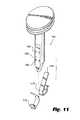
- FIGS. 7-11illustrate a third exemplary embodiment of a surgical access device in accordance with the invention, having opposed distal spring clips for engaging an abdominal wall of a patient;
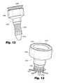
- FIGS. 12 and 13illustrate a fourth exemplary embodiment of a surgical access device in accordance with the invention, having expanding anchor elements at a distal end thereof, and a contractible body tube;
- FIGS. 14-16illustrate a fifth exemplary embodiment of a surgical access device in accordance with the invention, having opposed deployable anchor elements
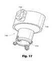
- FIGS. 17-26illustrate a sixth exemplary embodiment of surgical access devices in accordance with the invention, having circumferentially arranged deployable anchor elements
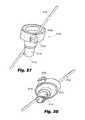
- FIGS. 27-29illustrate a seventh exemplary embodiment of a surgical access device in accordance with the invention having at least one slot formed in a distal body portion thereof to enhance a range of motion of a surgical instrument inserted therethrough;
- FIGS. 30-33illustrate an eighth exemplary embodiment of a surgical access device according to the invention, having distal coiled anchor elements
- FIGS. 34-35illustrate a surgical access device with radially deployable anchor elements actuated by one or more shafts
- FIGS. 36-41illustrate a surgical access device in accordance with a further embodiment of the invention, which can be provided with a proximal end cap;
- FIGS. 42-50illustrate a further embodiment of a surgical access device in accordance with the invention having a housing with a cover, in-turn with an optional removable lid, as well as a side-access port;
- FIG. 51illustrates still a further surgical access device in accordance with the invention having a plurality of side-access ports
- FIGS. 52-57illustrate a wound protector compatible with the surgical access devices, of the invention having an anchor portion, central tubular structure and curved sealing members;
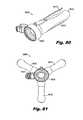
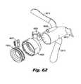
- FIGS. 58-62illustrate a further embodiment of a surgical access device in accordance with the invention, including a plurality of flexible atraumatic anchor portions, which extend outwardly from the body;
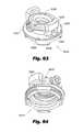
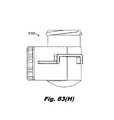
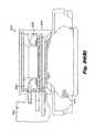
- FIGS. 63-69illustrate still a further embodiment of a surgical access device in accordance with the invention, including a nozzle assembly mounted for spatial adjustability with respect to a base portion thereof;
- FIGS. 70-76 (A)illustrate a nozzle assembly in accordance with the invention, including an upper portion and a lower portion;
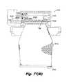
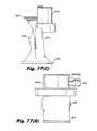
- FIGS. 77-83illustrate yet a further embodiment of a surgical access device in accordance with the disclosure, which is adapted for use with flexible wound retractors and the like;
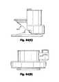
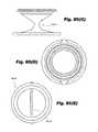
- FIGS. 84-85illustrate still another embodiment of a surgical access device in accordance with the invention, which is adapted for use with flexible wound retractors and the like.
- a surgical access device 100which is advantageously has a relatively low profile, allowing surgical instruments 190 inserted therethrough to be less restricted in movement than with more conventional surgical access devices.
- the access device 100includes a housing 120 , and a compliant access tube 110 extending distally from the distal end of the housing 120 .
- the access tube 110is adapted and configured to extend at least partially though an incision formed in the abdominal wall of a patient.
- the access tube 110has hyperbolic shape in cross section.
- An expanded-diameter distal portion of the access tube 110inhibits removal of the access device 100 from the incision formed in the patient.
- the length of the access tube 110can be sufficiently long so as to extend fully though the abdominal wall of the patient and into the peritoneal space.
- the access device 100can further include insufflation capability, can be adapted and configured to form a fluidic seal or barometric barrier around an instrument inserted therethrough and/or can be adapted to facilitate recirculation of insufflation gasses. Details of such capabilities are set forth in U.S. Pat. No. 7,182,752, U.S. Pat. No. 7,285,112, U.S. Pat. No. 7,338,473, U.S. Pat. Publication No. US 2007/0088275 and PCT Publication No. WO 2008/077080, which documents are incorporated herein by reference in their entirety.
- the surgical access device 100can include an a pressurized fluid plenum 123 defined within the housing 120 .
- the plenum 123is defined between the housing 120 , a lower insert 130 and an upper insert 140 .
- the plenum 123is in fluid communication with at least one nozzle 128 , and is configured to direct pressurized fluid in a substantially axial direction from the plenum 123 into a central lumen 118 of the access tube 110 to provide a constant gaseous seal around a surgical instrument inserted therethrough, and/or across the lumen 118 when an instrument is not inserted therethrough, for example.
- a recirculation chamber 121can be defined in the access device 100 , between the housing 120 and the lower insert 130 .
- One or more sealing elementssuch as resilient O-rings or the like, can be provided in seats 132 , 142 , which are formed respectively in each of the first and second inserts 130 , 140 .
- One or more openings 114can be provided between the lumen 118 and the recirculation chamber 121 to allow gasses to pass into the recirculation chamber 121 .
- One or more additional chambers or other fluid conduitscan further be provided, to facilitate fluid communication between a pressure-sensing device and/or a surgical insufflator, and the operative site.
- a fluid conduitcan be formed within the wall of or on the inner or outer surfaces of the access tube 110 .
- a separate tubecan be passed though the lumen 118 for such purpose, if so desired.
- a pressure sensing and/or insufflation aperture 424can simply be in fluid communication with the upper portion of the lumen 418 .
- connection 125is provided on the housing 120 , and has at least one channel formed therein, in fluid communication with one of the aforementioned chambers and/or conduits. It is in fluid communication with such chambers and/or conduits by passages formed therein and in the housing 120 .
- the connection 125facilitates connection of multiple conduits, which may be embodied in a single set, to the access device 100 quickly and simply.
- the conduits, in-turnare connected to the appropriate equipment, including insufflation devices, recirculation devices and the like.
- the housing 120 and the access tube 110can be detachable from one another.
- the access tube 110can be provided in assorted lengths and shapes, and with assorted features, as desired or required. Accordingly, a surgeon can decide before or during a procedure what length or diameter access tube 110 to use, and can attach it to the body 120 of the access device. Alternatively, a range of access devices of varying diameters, lengths and having varying features can be provided fully assembled to be available to the surgeon.
- the illustrated cross-section of the access tube 110which is taken in a plane parallel to the longitudinal axis 180 of the access device 100 is hyperbolic, and in three-dimensions is shaped as a hyperboloid of revolution.
- the cross-sectionin a plane perpendicular to the central axis 180 , for example, can be circular, oval, elliptical or otherwise oblong in shape.
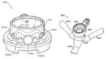
- a surgical access device 200 in accordance with the inventioncan be adapted and configured for use with any desired tubular surgical access device, such as a flexible wound retractor 310 ( FIG. 3 ), for example.
- Example wound retractorsare set forth in U.S. Pat. Nos. 5,524,644, 3,347,226, 3,347,227, 5,159,921, 5,524,644, 6,450,983, 6,254,534, 6,846,287, 5,672,168, 5,906,577, 6,142,936, 5,514,133, 7,238,154, 6,945,932, 6,908,430, 6,972,026, 5,741,298, or 6,945,932, which disclosures are incorporated herein by reference in their entirety.
- the wound retractorcan be inserted through an incision formed in the patient, and secured by any suitable means.
- the body 120can then be secured, such as by interference fit, friction fit, clamps, straps or otherwise secured to the proximal end of the wound retractor, for the purpose of providing insufflation, recirculation and/or filtration and/or fluidic sealing capability to prevent loss of abdominal pressure when insufflated, without introducing a mechanical seal.
- a flexible wound retractor 300which includes a sheath body 312 , distal ring 313 and proximal ring 311 is seated in a distally positioned groove 429 in an expanded-diameter portion of the housing 220 of the surgical access device 200 .
- the distal and proximal rings 311 , 313are typically made of a compliant material, such as a rubber, foam rubber or the like, and thus have an inherent shape and size.
- the housing 200can be applied thereto, with the proximal ring 311 compressing initially during insertion, and then expanding to fit within the groove 429 .
- the internal hoop stressesmaintain the ring 311 and thus the retractor 300 within the groove 429 , and inhibit unintentional removal therefrom.
- Alternate connections between the wound retractor 310 and the housing 200are conceived, including but not limited to use of clamp devices and the like, with the housing being seated at least partially within a lumen of the wound retractor, for example.
- the surgical access device 200 of FIG. 2-6includes a housing 220 , with a connector 225 extending therefrom.
- the internal components thereofwhich will be explained in more detail below in connection with FIG. 4-6 are held within the housing by a retainer, which is embodied as a snap ring or “circlip” 260 , which is used to maintain a relatively low profile, but other configurations are possible.
- the surgical access device 200is provided with a relatively low profile, allowing surgical instruments inserted therethrough to be less restricted in movement than with more conventional surgical access devices, as with the access device 100 of FIG. 1 .
- the access device 200includes a housing 220 , adaptable with a flexible wound retractor 310 extending distally from the distal end of the housing 220 .
- the access device 200can include insufflation capability, can be adapted and configured to form a fluidic seal or barometric barrier around an instrument inserted therethrough and/or can be adapted to facilitate recirculation of insufflation gasses.
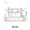
- the surgical access device 200includes a pressurized fluid plenum 423 defined within the housing 220 .
- the plenum 423is defined between the housing 220 , a lower insert 430 and an upper insert 440 .
- the plenum 423is in fluid communication with at least one nozzle 428 , and is configured to direct pressurized fluid in a substantially axial direction from the plenum 423 into a central lumen 418 of the wound retractor to provide a constant gaseous seal around a surgical instrument inserted therethrough, and/or across the lumen 418 when an instrument is not inserted therethrough, for example.
- a recirculation chamber 421can be defined in the access device 200 , between the housing 220 and the lower insert 430 .
- One or more sealing elementssuch as resilient O-rings or the like, can be provided in annular seats which are formed respectively in each of the first and second inserts 430 , 440 .
- An aperture 422is provided in the housing 220 between the lumen 118 and the connector 225 to allow gasses to pass into a recirculation portion of a connected system.
- One or more additional chambers or other fluid passageways or conduits 424can further be provided, to facilitate fluid communication between a pressure-sensing device and/or a surgical insufflator, and the operative site.
- the fluid conduitcan be formed within the wall of or on the inner or outer surfaces of a wound retractor connected thereto. Alternatively, a separate tube can be passed though the lumen 418 for such purpose, if so desired.
- a pressure sensing and/or insufflation aperture 424can simply be in fluid communication with the upper portion of the lumen 418 .
- connection 225is provided on the housing 220 , and has at least one channel formed therein, in fluid communication with one of the aforementioned chambers and/or conduits. It is in fluid communication with such chambers and/or conduits by passages formed therein and in the housing 220 .
- the connection 225facilitates connection of multiple conduits, which may be embodied in a single set, to the access device 200 .
- the conduits, in-turnare connected to the appropriate equipment, including insufflation devices, recirculation devices and the like.
- the cross-section or the lumen portion of the housing 220can be circular, oval, elliptical or otherwise oblong in shape.
- a proximal cap 650can be applied to the housing 220 , and can incorporate sound attenuation features, such as sound absorbing materials or sound attenuation surface features to absorb, cancel or reduce sound created by fluid flowing through the lumen 418 of the access device.
- An internal skirt 660is optionally provided, and is seated within the housing 220 and the lumen 418 . Apertures can be formed in the housing portion of the skirt 660 to allow fluid to enter the recirculation plenum 421 .
- a tube or other passagewaycan be integrated into the skirt 660 , in fluid communication with pressure sensing and/or insufflation components of attached systems, connected through the respective passageway of the connector 425 .
- FIGS. 7-11illustrate a further surgical access device 700 in accordance with the invention, which includes a housing 720 with connector 725 , with internal components that are substantially similar, and may include the same optional features to that of the foregoing embodiments, and which for simplicity will not be discussed in detail with respect to this embodiment.
- the surgical access device 700includes a different anchoring mechanism than that of the foregoing embodiments.
- the surgical access device 700includes spring anchors 715 , which are provided in tracks formed in or alternatively on a surface of the housing 720 , terminating in stops 716 .
- the spring anchorsare formed so as to secure the access device 700 to the abdominal wall of a patient, while preventing trauma thereto, and accordingly include a reverse bend at the distal end thereof.
- the spring anchorscan be maintained within the housing 720 , and not deployed, or can be deployed from a stowed position when the access device 700 is inserted.
- the spring anchors 715can be formed of any suitable material including but not limited to stainless steel or shape-memory alloys.
- the access device 700is provided with a compatible obturator 790 , having opposed planar slots 795 with stubs 792 extending into the slots, offset from a bottom surface of the slots 795 .
- a compatible obturator 790having opposed planar slots 795 with stubs 792 extending into the slots, offset from a bottom surface of the slots 795 .
- notches 1116are defines in the spring anchors 715 .
- the stubs 792pass through the notches 1116 and in combination with the slots 795 engage the spring anchors 715 and straighten them from their inherently curved configuration.
- the obturator 790can be used to hold the spring anchors 715 in a straightened configuration during insertion of the access device 700 , as well as during removal thereof from the patient.
- FIGS. 12-13illustrate a further surgical access device 1200 in accordance with the invention, which includes a housing 1220 with connector 1225 , with internal components that are substantially similar, and may include the same optional features to those of the foregoing embodiments, and which for simplicity will not be discussed in detail with respect to this embodiment.
- the surgical access device 1200includes still a different anchoring mechanism than that of the foregoing embodiments.
- the surgical access device 1200includes spring anchors 1215 , which are maintained during insertion of the access device 1200 by a distal end cap 1210 , which can function as or be integrated with a surgical obturator 1290 .
- the cap 1210is removed by urging the cap distally. The cap 1210 can be reapplied to the access device 1200 to allow for removal of the access device 1200 .
- the spring anchors 1215can be formed of any suitable material, including shape memory alloys.
- the body of the access deviceincludes an adjustable bellows portion 1230 to aid in securing the access device 1200 to the abdominal wall.
- the distal end portion 1229 of the bodycan be pulled proximally to effectively pinch the abdominal wall, securing the access device 1200 thereto.
- Such a connectioncan be accomplished by way of a spring-loaded component which is maintained in an extended configuration during insertion of an obturator 1290 , or alternatively a cable arrangement attached to the distal end portion 1229 and pulled proximally.
- FIGS. 14-16illustrate a further surgical access device 1400 in accordance with the invention, which includes a housing 1420 with connector 1425 , with internal components that are substantially similar, and may include the same optional features to those of the foregoing embodiments, and which for simplicity will not be discussed in detail with respect to this embodiment.
- the surgical access device 1400includes distal anchor elements 1415 , which can be formed of any suitable material, including but not limited to stainless steel or a shape memory alloy, for example.
- the anchor elements 1415are maintained in a straight orientation ( FIG. 14 ), when engaged with a distal end portion 1410 of a surgical obturator 1490 .
- the track 1417is integrated with the anchor elements 1415 and is adapted to engage one or more protrusions on the obturator 1490 to maintain the anchor elements 1415 in the desired position.
- a frame 1416 of the anchor elements 1415defines the overall shape, and terminates as pivots 1419 .
- the frame 1416can be provided with a coating 1418 , which can be made of a cushioning material to minimize trauma to the patient and/or to enhance anchoring of the access device 1400 .
- the cushioning materialcan be silicone rubber for example, but can be another suitable material, and can extend into a web 1481 define within the frame 1416 , effectively increasing the surface area of the anchor element 1415 .
- FIG. 16shows the access device 1400 with the obturator 1490 removed therefrom.
- FIGS. 17-26illustrate a further embodiment of a surgical access device 1700 in accordance with the invention, and detailed views of anchoring elements 1715 thereof.
- the surgical access deviceis similar to the embodiment of FIGS. 14-16 , and includes a housing 1720 with internal components as set forth above, a connection element 1725 and anchor elements 1715 .
- an obturator for use with the access device 1700includes a distal end portion 1810 , which engages the anchor elements 1715 by way of articulating hooks 1811 . Upon insertion, the articulating hooks 1811 . The anchor elements 1715 are maintained in a straight position during insertion and are released when the access device 1700 is fully inserted through the abdominal wall of the patient.
- the access device 1700includes a plurality of circumferentially arranged anchors 1715 , which are formed of a material such but not limited to stainless steel or shape-memory alloys. Alternatively, with this or other embodiments described herein, resilient polymeric materials can be used. Optional features including coverings, a web element or the like can be applied to advantageous effect.
- FIG. 21is a top view of the surgical access device 1700 , which illustrates an overall cross-sectional shape and lumen shaped substantially as an ellipse. As set forth above, alternate shapes are possible, including but not limited to circular, cat-eye shape or oblong of another configuration.
- the anchors 1715include a main body 2275 , spring elements 2273 , pins 2271 extending from the body 2275 , one or more struts 2277 .
- the body 2275can be formed of any suitable material, including but not limited to polymeric materials.
- the tendency of the anchors 1715 to curveis imparted in the illustrated embodiment by way of the spring elements 2273 , which as with foregoing embodiments can be formed of any suitable material including but not limited to polymeric materials and metals, including shape memory alloys.
- the pins 2271are provided to secure the anchors 1715 to the body 1720 of the surgical access device 1700 .
- Further protrusions 2279can be provided on the anchors 1715 to additionally secure the anchors 1715 to the body 1720 .
- FIGS. 27-29illustrate an access device 2700 which includes a slot 2712 formed in a distal end portion 2710 of the body 2720 thereof.
- This featurecan be applied to any other embodiment set forth herein, which includes an elongated body.
- the slotallows for extended range of motion of a surgical instrument 2799 inserted through the access device 2700 .
- the housing 2720includes a connection 2725 .
- the cross-sectional shapeis substantially elliptical, but alternatively can have another shape, as mentioned above.
- FIGS. 30-33illustrate a further embodiment of a surgical access device 3000 in accordance with the invention, having a housing 3020 with connection 3025 .
- the surgical access device 3000includes circularly coiled anchor elements 3015 circumferentially arranged in a distal end portion thereof.
- An axially movable actuator 3076is provided, in connection with the anchor elements 3015 , which when contracted are housed within the body 3020 of the access device 3000 .
- the actuator 3076When the actuator 3076 is urged distally, the anchor elements 3015 extend from the distal end of the housing 3020 , and coil in radial planes, perpendicular to a longitudinal axis of the access device 3000 .
- the anchor elements 3015When deployed, the anchor elements 3015 abut the abdominal wall, thereby helping anchor the access device 3000 .
- the anchor elements 3015can be formed of a spring material, which can be, for example, a resilient polymeric material, or a metal such as stainless steel or a shape memory alloy.
- FIGS. 34 and 35illustrate a surgical access device 3400 having yet a further alternative anchoring mechanism, with radially deployable anchor elements 3415 , actuated by one or more shafts 3417 provided in a housing 3420 thereof.
- the anchor elements 3415are deployed to anchor the access device 3400 to the abdominal wall of the patient.
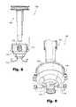
- FIGS. 36-41illustrate a surgical access device 3600 similar to the embodiment illustrated in FIGS. 2-5B .
- the surgical access device 3600includes an upper housing portion 3620 and a distal, or lower, housing portion 3627 .
- the lower housing portion 3627includes a discontinuous bottom end, with extensions 3628 , being interrupted by openings 3629 .
- Such an arrangementfacilitates connection with and removal from a detachable body tube, such as the flexible proximal ring 311 of a flexible wound retractor.
- a nozzle assembly 3630is provided in the housing 3620 .
- a lid assembly 3640is optionally provided, and as embodied includes an engagement portion 3641 , a lid portion 3643 and a hinge 3645 arranged therebetween.
- the engagement portion 3641is a ring that surrounds the housing 3620 . However, it is to be understood that this element need not be limited to such a configuration.
- the engagement portion 3641can be connected to the housing 3620 by friction fit, adhesive, bonding such as solvent, friction welding or ultrasonic welding, for example.
- FIGS. 42-50illustrate a further embodiment of a surgical access device 4200 in accordance with the invention.
- the surgical access device 4200includes a housing 4220 , and a cover 4229 with an optional removable lid 4228 .
- the cover 4229is preferably fit over the body 4220 and serves to reduce sound from fluid flowing through the access device 4200 to an observer, for example, in the operating room during use of device 4200 .
- the cover 4229is, in accordance with one aspect, formed of a sound-absorbing material, at least in part. Further, the cover 4229 can be removed quickly during a surgical procedure if increased access to a surgical site is required.
- the housing 4220includes, defined therein, a side access port 4226 , which can be provided with a pivotable or flexible door 4227 to reduce noise coming through the side access port 4226 when not in use.
- surgical instruments or accessoriessuch as sutures can be inserted through the port 4226 , or specimens can be removed therethrough.
- the configuration of a nozzles, provided in the surgical access device 4200permits openings to the side of the housing 4220 , as with the side access port 4226 .
- a pressure barrieris formed below the port 4226 , and as such, the port 4226 experiences lower pressure than those experienced in the abdomen under insufflation. Accordingly, insufflation gasses remain in the abdominal cavity, or are recirculated through the surgical access device 4200 .
- a plurality of protrusions 4281can be provided adjacent to the side access port 4226 .
- the protrusionsserve to hold and inhibit sliding of surgical instruments inserted through the port 4226 , and also serve as fulcrums for applying leverage to surgical instruments inserted through the port 4226 .
- a plurality of standoffs 4281can be provided to maintain a positioning of a nozzle insert in the housing 4220 .
- an exemplary connection arrangement between the cover 4229 and lid 4228is illustrated, whereby studs 4298 extend from the lid 4228 , and engage corresponding apertures 4299 in the cover 4229 .
- a circlip 260can be provided for securing a nozzle insert within the housing 4220 .
- FIG. 51illustrates a further surgical access device 5100 , which, similar to the embodiment of FIGS. 42-50 , is provided with side access ports 5191 a - e in the housing 5120 thereof.
- the surgical access device 5100is not illustrated with a nozzle insert for simplicity of illustration, but one would be provided, as with other embodiments set forth herein.
- the side access ports 5191 a - epermit insertion of multiple instruments through a surgical incision, while maintaining positioning thereof in respective ports.
- a pressure barrieris formed below the ports 5191 a - e , and therefore no mechanical seals are required.
- one or more ports 5191 a - ccan be used with an endoscope, and such an arrangement can also facilitate use with robotic surgical systems, by defining secure positions in which instruments can be placed, relative to a patient's anatomy.
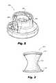
- FIG. 52-57illustrate a wound protector 5200 , compatible with the foregoing surgical access devices.
- the wound protector 5200includes a proximal end portion 5216 , a central tubular structure 5210 , and a distal anchor portion 5214 .
- the anchor portion 5214is supported by the central tubular structure 5210 by a web 5212 .
- Apertures 5213can be defined in the web 5212 to facilitate manipulation of the wound protector 5200 and material reduction.
- the wound protector 5200is preferably molded of an elastomeric material, but can optionally be provided with an internal structure of a shape-memory alloy, if desired.
- the proximal end portion 5216includes an upper surface 5218 with standoffs 5219 , which, as illustrated are configured to directly interface with nozzle components for forming pressure barriers, such as those described herein.
- the surface 5218can partially define a chamber or plenum, such as a return plenum for recirculation capability.
- the central tubular portion 5210includes an undulating configuration, best seen in the top view of FIG. 54 , wherein a substantially sinusoidal aperture 5281 is defined between opposite walls 5280 , 5282 .
- the aperture 5281can be completely sealed by the walls 5280 , 5282 , or alternatively can be configured so as to remain partially open.
- the illustrated configurationpermits passage of one or more instruments through the lumen 5299 and aperture 5281 , while the walls 5280 , 5282 move away or “unfold” from the lumen, but without stretching. In this manner, excessive forces are not applied to instruments inserted therethrough.
- the forces experienced passing through the aperture 5281are substantially less than for an instrument passing through a typical “duckbill” type seal member.
- the configuration of the sinusoidal aperture 5281 and opposed walls 5280 , 5282reduces, the overall cross-sectional area of available area of the lumen 5299 , as compared with a fully open (e.g. circular) lumen.
- the wound protector 5200can be inserted through in incision by inverting the web 5212 and distal anchor portion 5214 , and inserting the distal end of the wound protector 5200 through the incision. Once inserted sufficiently far, the distal anchor portion 5214 then deploys and maintains the position of the wound protector 5200 in the incision.
- FIG. 58-62illustrate a further embodiment of a surgical access device 5800 in accordance with the invention.
- the surgical access device 5800preferably includes a plurality of flexible atraumatic anchor portions 5810 , which extend outwardly from the body 5820 .
- Any nozzle configurationcan be provided in connection with this embodiment, but as illustrated, the nozzle configuration is that 7000 of FIGS. 70-76 (A) (described hereinbelow).
- the surgical access device 5800 as well as other surgical access devices described hereinneed not only be provided in connection with a pressure-barrier nozzle (e.g. nozzle 7000 ), but can be advantageously provided instead, or in addition, with more traditional physical sealing members, such as septum seals, duckbill-type seals, and so on.
- a side access port 5828is provided, which can be advantageously used to permit passage of and hold an endoscope, for example. In such a manner, the endoscope can be inserted and can remain in position, while other surgical instruments are inserted through the lumen 5819 .
- the housing 5820as illustrated, is substantially elliptical. Alternatively, the housing 5820 can be round or another shape, for example, as with any embodiment set for the herein.
- connection 5827 for a tube setis provided on the housing 5820 and offset therefrom with an extension 5825 , which removes any connection from the area of a patient's skin, and thus minimizes any trauma to the patient's skin in the area of the incision, during a surgical procedure.
- the anchor portions 5810are preferably atraumatic in configuration, and therefore have a relatively wide and rounded configuration.
- the anchor portions 5810can be formed of a polymeric material uniquely, or can be formed of a plurality of materials, such as a polymer molded over a metal structure, such as one formed of a spring steel or a shape-memory alloy, for example.
- FIG. 60illustrates the surgical access device 5800 in configuration for insertion through an incision.
- the anchor portions 5810are preferably extended from a resting (relaxed) position into a substantially longitudinally-aligned position.
- the anchor portions 5810can be inserted through an incision, maintained in position by hand, or by an insertion device, and then released within the abdominal cavity, when the anchor portions 5810 return to their resting state, and hold the surgical access device 5800 in position in the incision.
- FIGS. 63-69illustrate still a further embodiment of a surgical access device 6300 in accordance with the invention.
- the surgical access device 6300includes a nozzle assembly 6330 mounted for spatial adjustability with respect to a base portion 6328 of the surgical access device 6300 , and thus an incision to which the surgical access device 6300 is mounted.
- a tube connection 6327is provided on the nozzle assembly 6330 , which is held by opposed stanchions 6323 , having spherical inner surfaces for mating with a spherical outer surface of the nozzle assembly 6330 .
- the nozzle assembly 6330is permitted to rotate in a substantially spherical path, with respect to the stanchions 6323 , the plate portion 6326 to which the stanchions 6323 are secured, a lower portion 6328 of the surgical access device 6300 and therefore, to the incision.
- the plate portion 6326and therefore, the stanchions 6323 and nozzle assembly 6323 are also linearly adjustable, as illustrated, by way of pins 6322 , engaging nuts 6325 , and corresponding slots 6324 formed in the plate portion 6326 .
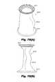
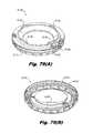
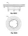
- FIGS. 70-76illustrate various views of a nozzle assembly 7000 in accordance with the invention.
- the nozzle assembly 7000includes an upper portion 7790 and a lower portion 7780 .
- Standoffs 7792 and corresponding recesses 7783are provided to maintain relative spacing, and a pressure plenum therebetween.
- the upper portion 7790 and lower portion 7780are sealed to the housing, into which they are inserted, by seal elements, such as o-rings, held in circumferential grooves 7789 , 7799 on the outside of the lower portion 7780 and upper portion 7790 , respectively.
- seal elementssuch as o-rings
- the upper portion 7790 and lower portion 7780can be sealed at their inner-most edge, causing pressurized fluid to be diverted through discrete jets 7781 distributed about the lower portion 7780 .
- a stepped interface 7079can be provided between the upper portion 7790 and the lower portion 7780 .
- the upper portion 7790 and the lower portion 7780can be mutually adhered at the protrusions 7792 and or at the stepped interface 7079 , for example, to create a sub-assembly and enhance structural stability of the nozzle assembly 7000 .
- FIGS. 77(A)-77(G)a cut away view of a surgical access device 8100 is presented.
- Device 8100is made by assembling a number of nested components discussed in further detail below.
- device 8100includes, in a nested configuration, an outer cannula or body 8120 , an inner cannula/wound retractor 8310 , a ring jet assembly 8130 , a tube center component 8140 and a fluid manifold 8150 attached to an exterior portion of the outer cannula 8120 .
- a cap 8160may also be provided as illustrated in FIGS. 81(A)-81(B) and as discussed in detail below.
- outer cannula 8120has a proximal end 8122 helping to define a proximal region 8122 A, a distal end 8124 helping to define a distal region 8124 A, and defines a longitudinal bore 8126 therethrough.
- the external surface of outer cannula 8120defines thereon a mounting fixture 8125 to receive a fluid manifold 8150 , described below.
- fluid manifold 8150defines therethrough three fluid passages that initiate at ports 8152 on the top of manifold 8150 and that terminate at slots 8123 defined through the side of outer cannula 8120 .
- Each of the aforementioned fluid passagescooperate with the other portions of device 8100 to define fluid passages, or plena.
- Each plenumannotated by reference numerals 8520 , 8530 and 8540 , serves a different purpose in operation of device 8100 as described below.
- Manifold 8150is preferably permanently joined to outer cannula 8120 to ensure that the fluid plena remain fluidly separated from each other by way of a gas tight seal.
- surgical access device 8100 , 8200can be adapted and configured for use with any desired tubular surgical access device, such as a flexible inner cannula/wound retractor 8310 , 8410 ( FIGS. 78(A)-78(E), 85(A)-85(E) ), for example.
- a flexible inner cannula/wound retractor 8310 , 8410FIGS. 78(A)-78(E), 85(A)-85(E)
- wound retractorsare set forth in U.S. Pat. Nos.
- the wound retractor 8310can be inserted through an incision formed in the patient, and secured by any suitable means.
- the outer cannula 8120is assembled with retractor 8310 in advance of any medical procedure.
- a flexible wound retractor 8310which includes a sheath body 8312 , distal ring 8313 and proximal ring 8311 .
- Proximal ring 8311is held in place by the assembly of nested components 8120 , 8130 , 8140 .
- the distal and proximal rings 8311 , 8313are typically made of a compliant material, such as a rubber, foam rubber or the like, and thus have an inherent shape and size.
- tube center component 8140 and ring jet assembly 8130nest to form one or more fluid jets.
- tube center component 8140defines one or more detents 8143 on its outer surface.
- the detents 8143cooperates with the inner surface of ring assembly 8130 to form a conduit that is in fluid communication with high pressure plenum 8520 ( FIG. 77(B) ).
- High pressure plenum 8520is pressurized with a working gas so as to drive a high speed gas flow through each of the jets disposed about the periphery of the distal circumferential interface 8524 of the center component 8140 and the ring jet 8130 .
- a fluid tight seal about plenum 8520is ensured by seals 8554 , 8556 disposed in circumferential grooves 8141 , 8131 formed in each of center tube portion 8140 and ring jet 8130 , respectively.
- Proximal ring 8311 of inner cannula/wound retractor 8310is captured between and seals against inner ridge 8129 of outer cannula 8120 and distal circumferential face 8136 of ring jet 8130 .
- these componentscooperate to define sensing plenum 8540 in cooperation with dedicated passageway 8542 in manifold 8150 and exhaust or recirculation plenum 8530 for evacuating gas and other fluids from device 8100 and/or the abdomen of the patient into a filtration and recirculation assembly (not shown). Openings 8135 in ring jet 8130 facilitate passage of recirculating fluids.
- the gas jetsexit and wrap around the outer distal surface of the center tube component before breaking free of the surface, thus obtaining some angularity with respect to a longitudinal axis of the trocar, such that the main direction of the jet flow is generally off-axis, indicated for example by arrow “A” in FIG. 77(B) .
- the momentum of the gas exiting the circumferentially disposed peripheral jetsforms a pressure gradient inside the bore 8106 of the device 8100 , such that the pressure at the distal end 8102 of the device can be about 15 mm of Hg higher than the atmospheric pressure outside the trocar in the operating room.
- Proper axial spacing between center tube assembly 8140 and ring jet 8130is ensured by the height of proximal spacers 8132 disposed on the proximal face of the ring jet 8130 .
- sensing plenum 8540includes one or more pressure sensors (not shown) in a fluid flow control unit (not shown) to maintain the pressure of a patient's abdomen at a preselected pressure (e.g., 15 mm Hg).
- a preselected pressuree.g. 15 mm Hg.
- Suitable gas flow control unitsare described, for example, in Provisional Patent Application Ser. No. 61/246,921, and provisional Patent Application Ser. No. 61/384,412, filed Sep. 20, 2010, each of which is incorporated by reference herein in its entirety.
- the flow control unitdecreases the delivery of gas to plenum 8520 , resulting in less gas being delivered through the high speed jets and into the bore 8106 of the device 8100 .
- the flow control unitincreases the delivery of gas to plenum 8520 , resulting in more gas being delivered through the high speed jets and into the bore 106 of the device 8100 .
- the outer cannula 8120 and the inner cannula/wound retractor 8310can be detachable from one another.
- the inner cannula/wound retractor 8310can be provided in assorted lengths (see, e.g., the embodiment of FIGS. 84-85 ) and shapes, and with assorted features, as desired or required.
- the inner cannula/wound retractor 8310 of FIG. 2defines an “S”-shaped narrowed region 8315 ( FIG. 2(E) ) while that of FIG. 85 defines a straight elongate narrowed region 8415 ( FIG. 85(E) ).
- a surgeoncan decide before or during a procedure what length or diameter inner cannula/wound retractor 8310 to use, and can attach it to the outer cannula 8120 of the access device 8100 .
- a range of access devices of varying diameters, lengths and having varying featurescan be provided fully assembled to be available to the surgeon.
- the access device 8100can include insufflation capability, can be adapted and configured to form a fluidic seal or barometric barrier around an instrument inserted therethrough and/or can be adapted to facilitate recirculation of insufflation gasses.
- a proximal cap 8160can be applied to the device 8100 , and if desired can incorporate sound attenuation features, such as sound absorbing materials or sound attenuation surface features to absorb, cancel or reduce sound created by fluid flowing through the bore 8106 of the access device 8100 .
- cap 8160can be provided with an internal circumferential groove 8162 that is adapted and configured to engage flange 8122 B (illustrated in FIG. 77(F) ) at proximal end 8122 of outer cannula 8120 .
- FIGS. 84-85illustrate a further surgical access device 8200 in accordance with the disclosure, which includes an outer cannula 8220 , a ring jet 8230 , a center tube adapter 8240 and manifold 8250 .
- Embodiment 8200is substantially the same as embodiment 8100 , but has a truncated inner cannula/wound retractor 8410 .
Landscapes
- Health & Medical Sciences (AREA)
- Life Sciences & Earth Sciences (AREA)
- Surgery (AREA)
- Heart & Thoracic Surgery (AREA)
- Veterinary Medicine (AREA)
- General Health & Medical Sciences (AREA)
- Engineering & Computer Science (AREA)
- Biomedical Technology (AREA)
- Public Health (AREA)
- Animal Behavior & Ethology (AREA)
- Molecular Biology (AREA)
- Nuclear Medicine, Radiotherapy & Molecular Imaging (AREA)
- Medical Informatics (AREA)
- Pathology (AREA)
- Physics & Mathematics (AREA)
- Anesthesiology (AREA)
- Hematology (AREA)
- Biophysics (AREA)
- Pulmonology (AREA)
- Optics & Photonics (AREA)
- Gastroenterology & Hepatology (AREA)
- General Physics & Mathematics (AREA)
- Astronomy & Astrophysics (AREA)
- Oral & Maxillofacial Surgery (AREA)
- Radiology & Medical Imaging (AREA)
- Surgical Instruments (AREA)
Abstract
Description
Claims (10)
Priority Applications (1)
| Application Number | Priority Date | Filing Date | Title |
|---|---|---|---|
| US13/388,644US9597112B2 (en) | 2008-10-10 | 2010-10-08 | Low-profile surgical access devices with anchoring |
Applications Claiming Priority (7)
| Application Number | Priority Date | Filing Date | Title |
|---|---|---|---|
| US10447508P | 2008-10-10 | 2008-10-10 | |
| PCT/US2009/060299WO2010042915A2 (en) | 2008-10-10 | 2009-10-10 | Low-profile surgical access devices with anchoring |
| US25052109P | 2009-10-11 | 2009-10-11 | |
| US12/577,189US9289233B2 (en) | 2008-10-10 | 2009-10-11 | Low-profile surgical access devices with anchoring |
| US37093810P | 2010-08-05 | 2010-08-05 | |
| PCT/US2010/051955WO2011044448A2 (en) | 2009-10-10 | 2010-10-08 | Low-profile surgical access devices with anchoring |
| US13/388,644US9597112B2 (en) | 2008-10-10 | 2010-10-08 | Low-profile surgical access devices with anchoring |
Related Parent Applications (2)
| Application Number | Title | Priority Date | Filing Date |
|---|---|---|---|
| US12/577,189ContinuationUS9289233B2 (en) | 2006-10-06 | 2009-10-11 | Low-profile surgical access devices with anchoring |
| PCT/US2010/051955A-371-Of-InternationalWO2011044448A2 (en) | 2008-10-10 | 2010-10-08 | Low-profile surgical access devices with anchoring |
Related Child Applications (1)
| Application Number | Title | Priority Date | Filing Date |
|---|---|---|---|
| US15/355,882ContinuationUS20190167302A9 (en) | 2008-10-10 | 2016-11-18 | Low-profile surgical access devices with anchoring |
Publications (2)
| Publication Number | Publication Date |
|---|---|
| US20130012782A1 US20130012782A1 (en) | 2013-01-10 |
| US9597112B2true US9597112B2 (en) | 2017-03-21 |
Family
ID=42101253
Family Applications (2)
| Application Number | Title | Priority Date | Filing Date |
|---|---|---|---|
| US12/577,189Active2033-11-10US9289233B2 (en) | 2006-10-06 | 2009-10-11 | Low-profile surgical access devices with anchoring |
| US13/388,644Active2032-11-27US9597112B2 (en) | 2008-10-10 | 2010-10-08 | Low-profile surgical access devices with anchoring |
Family Applications Before (1)
| Application Number | Title | Priority Date | Filing Date |
|---|---|---|---|
| US12/577,189Active2033-11-10US9289233B2 (en) | 2006-10-06 | 2009-10-11 | Low-profile surgical access devices with anchoring |
Country Status (7)
| Country | Link |
|---|---|
| US (2) | US9289233B2 (en) |
| EP (1) | EP2349033B1 (en) |
| JP (1) | JP5745413B2 (en) |
| KR (3) | KR101829726B1 (en) |
| CN (1) | CN102264309B (en) |
| ES (1) | ES2817573T3 (en) |
| WO (1) | WO2010042915A2 (en) |
Cited By (4)
| Publication number | Priority date | Publication date | Assignee | Title |
|---|---|---|---|---|
| US10405884B2 (en) | 2017-10-23 | 2019-09-10 | Conmed Corporation | Devices for performing minimally invasive surgery having rotating multiport access |
| US10413324B2 (en) | 2017-10-23 | 2019-09-17 | Conmed Corporation | Devices for performing minimally invasive surgery having foam support housing |
| US10463396B2 (en) | 2017-10-23 | 2019-11-05 | Conmed Corporation | Devices for performing minimally invasive surgery having bellows support housing |
| US11013530B2 (en) | 2019-03-08 | 2021-05-25 | Medos International Sarl | Surface features for device retention |
Families Citing this family (36)
| Publication number | Priority date | Publication date | Assignee | Title |
|---|---|---|---|---|
| KR101829726B1 (en) | 2008-10-10 | 2018-02-19 | 서지퀘스트, 인코포레이티드 | Low-profile surgical access devices with anchoring |
| US20190167302A9 (en)* | 2008-10-10 | 2019-06-06 | Surgiquest, Inc. | Low-profile surgical access devices with anchoring |
| WO2010068265A1 (en) | 2008-12-10 | 2010-06-17 | Minimally Invasive Devices, Llc | Systems and methods for optimizing and maintaining visualization of a surgical field during the use of surgical scopes |
| JP5415925B2 (en)* | 2009-03-02 | 2014-02-12 | オリンパス株式会社 | Endoscope |
| US8747297B2 (en)* | 2009-03-02 | 2014-06-10 | Olympus Corporation | Endoscopic heart surgery method |
| US8206291B2 (en)* | 2009-03-27 | 2012-06-26 | Tyco Healthcare Group Lp | Portal device |
| EP2481377A4 (en)* | 2009-09-22 | 2017-12-20 | Olympus Corporation | Space-securing device |
| US8932212B2 (en) | 2009-10-01 | 2015-01-13 | Covidien Lp | Seal anchor with non-parallel lumens |
| EP2485664B1 (en)* | 2009-10-10 | 2019-02-27 | SurgiQuest, Incorporated | Low-profile surgical access devices |
| US20110112373A1 (en)* | 2009-11-10 | 2011-05-12 | Trans1 Inc. | Soft tissue access apparatus and methods for spinal surgery |
| US9078562B2 (en) | 2010-01-11 | 2015-07-14 | Minimally Invasive Devices, Inc. | Systems and methods for optimizing and maintaining visualization of a surgical field during the use of surgical scopes |
| JP5914466B2 (en)* | 2010-05-24 | 2016-05-11 | サージクェスト,インコーポレーテッド | Automatic surgical device |
| US20110301419A1 (en)* | 2010-06-07 | 2011-12-08 | Brandon Wesley Craft | Pressure feedback access ports for minimally invasive surgery |
| JP5968886B2 (en) | 2010-08-04 | 2016-08-10 | ミニマリー インべーシブ デバイシーズ, インコーポレイテッド | System and method for optimizing and maintaining operative field visualization while using a surgical microscope |
| JP6396657B2 (en)* | 2010-10-01 | 2018-09-26 | アプライド メディカル リソーシーズ コーポレイション | Natural orifice surgery system |
| US9522017B2 (en) | 2010-12-03 | 2016-12-20 | Minimally Invasive Devices, Inc. | Devices, systems, and methods for performing endoscopic surgical procedures |
| US9149265B2 (en) | 2011-02-26 | 2015-10-06 | Abbott Cardiovascular Systems, Inc. | Hinged tissue support device |
| WO2012122263A2 (en) | 2011-03-08 | 2012-09-13 | Surgiquest, Inc. | Trocar assembly with pneumatic sealing |
| JP5779076B2 (en)* | 2011-10-17 | 2015-09-16 | 猛 大平 | Single-hole endoscopic surgical port |
| WO2014100210A1 (en) | 2012-12-19 | 2014-06-26 | Surgiquest, Inc. | Coupling for connecting a tube set to a trocar |
| US9486132B2 (en)* | 2013-01-17 | 2016-11-08 | Abbott Cardiovascular Systems, Inc. | Access device for accessing tissue |
| WO2014151824A1 (en) | 2013-03-14 | 2014-09-25 | Minimally Invasive Devices, Inc. | Fluid dispensing control systems and methods |
| ES2806266T3 (en) | 2013-03-15 | 2021-02-17 | Applied Med Resources | Trocar Surgical Seal Gasket |
| WO2015084157A1 (en)* | 2013-12-04 | 2015-06-11 | Fortimedix Surgical B.V. | Access device and assembly comprising such device |
| USD753303S1 (en) | 2014-07-29 | 2016-04-05 | Ethicon Endo-Surgery, Llc | Trocar |
| JP7080642B2 (en)* | 2015-04-23 | 2022-06-06 | アプライド メディカル リソーシーズ コーポレイション | Tissue retrieval system and method |
| US10076358B2 (en)* | 2015-09-01 | 2018-09-18 | Surgiquest, Inc. | Multi-port access device for minimally invasive surgical procedures |
| US10213194B2 (en) | 2016-09-27 | 2019-02-26 | Ethicon, Inc. | Surgical retraction systems including sternal retractors and hemostatic inserts |
| US10806490B2 (en) | 2017-03-08 | 2020-10-20 | Conmed Corporation | Single lumen gas sealed access port for use during endoscopic surgical procedures |
| CN106963379B (en)* | 2017-03-17 | 2020-08-21 | 中国人民解放军第三军医大学第一附属医院 | Terahertz imaging system |
| JP2021164491A (en)* | 2018-04-11 | 2021-10-14 | オリンパス株式会社 | Endoscope fluid controller |
| TWI865458B (en)* | 2018-08-17 | 2024-12-11 | 紐西蘭商費雪派克保健有限公司 | Venting surgical cannula and system for providing gases to a patient |
| WO2020036498A1 (en)* | 2018-08-17 | 2020-02-20 | Fisher & Paykel Healthcare Limited | Directed gas flow surgical cannula for providing gases to a patient |
| CN109124738B (en)* | 2018-08-28 | 2021-02-09 | 浙江天松医疗器械股份有限公司 | Puncture outfit casing pipe and use method of inner pipe and outer pipe thereof |
| US10932818B2 (en) | 2019-05-07 | 2021-03-02 | Covidien Lp | Removable seal assembly and access system including the same |
| US20220211263A1 (en)* | 2021-03-23 | 2022-07-07 | Axcess Instruments Inc. | Multi-piece access port imaging systems |
Citations (75)
| Publication number | Priority date | Publication date | Assignee | Title |
|---|---|---|---|---|
| US4184510A (en) | 1977-03-15 | 1980-01-22 | Fibra-Sonics, Inc. | Valued device for controlling vacuum in surgery |
| US4535773A (en) | 1982-03-26 | 1985-08-20 | Inbae Yoon | Safety puncturing instrument and method |
| US4735603A (en) | 1986-09-10 | 1988-04-05 | James H. Goodson | Laser smoke evacuation system and method |
| US4792335A (en) | 1987-02-11 | 1988-12-20 | Goosen Carl C | Pressure controlled valve apparatus |
| US4869717A (en) | 1988-04-25 | 1989-09-26 | Adair Edwin Lloyd | Gas insufflation needle with instrument port |
| US5002557A (en) | 1989-04-06 | 1991-03-26 | Hasson Harrith M | Laparoscopic cannula |
| US5013294A (en) | 1987-11-17 | 1991-05-07 | Richard Wolf Gmbh | Insufflation device for endoscopic intervention |
| US5190068A (en) | 1992-07-02 | 1993-03-02 | Brian Philbin | Control apparatus and method for controlling fluid flows and pressures |
| US5199944A (en) | 1990-05-23 | 1993-04-06 | Ioan Cosmescu | Automatic smoke evacuator system for a surgical laser apparatus and method therefor |
| US5203767A (en) | 1991-01-08 | 1993-04-20 | Cloyd David W | Laparoscopic surgical gauze and the like |
| EP0323018B1 (en) | 1987-12-31 | 1993-06-16 | United States Surgical Corporation | Self-seating flapper valve for an insufflation cannula assembly |
| US5284473A (en) | 1991-07-16 | 1994-02-08 | C. R. Bard, Inc. | Perfusion catheter with flow amplifier |
| US5290249A (en) | 1990-10-09 | 1994-03-01 | Vance Products Incorporated | Surgical access sheath |
| US5300047A (en) | 1992-09-29 | 1994-04-05 | Beurrier Henry R | Trocar cannula and catheter |
| US5312351A (en) | 1993-01-29 | 1994-05-17 | Gerrone Carmen J | Combined pneumo-needle and trocar apparatus |
| US5328458A (en) | 1991-12-03 | 1994-07-12 | Olympus Optical Co., Ltd. | Insufflation apparatus |
| US5366446A (en) | 1993-11-17 | 1994-11-22 | Unisurge, Inc. | Introducer assembly |
| US5429483A (en) | 1989-09-22 | 1995-07-04 | Tamari; Yehuda | Pressure sensitive valves for extracorporeal pumping |
| WO1996001132A1 (en) | 1994-07-01 | 1996-01-18 | Northgate Technologies Incorporated | High flow insufflation instrument for laparoscopic surgery |
| US5545150A (en) | 1994-05-06 | 1996-08-13 | Endoscopic Concepts, Inc. | Trocar |
| US5545179A (en)* | 1995-07-21 | 1996-08-13 | Ethicon Endo-Surgery, Inc. | Endoscopic access assembly |
| US5556386A (en) | 1995-04-03 | 1996-09-17 | Research Medical, Inc. | Medical pressure relief valve |
| DE19523685A1 (en) | 1995-07-04 | 1997-01-09 | Guenter Schaller | Means of assistance for use with a trocar - has hollow body formed by two elastomers with suction source connected to it and gas supply from insufflator connected to other side of valve to chamber. |
| US5720759A (en) | 1993-07-14 | 1998-02-24 | United States Surgical Corporation | Seal assembly for accommodating introduction of surgical instruments |
| WO1998019736A1 (en) | 1996-11-04 | 1998-05-14 | Frederick Paget Milsom | Cardiac recovery |
| US5800381A (en) | 1994-02-25 | 1998-09-01 | Ognier; Jean-François | Medical gas insufflator with automatic gas flow control |
| US5849005A (en) | 1995-06-07 | 1998-12-15 | Heartport, Inc. | Method and apparatus for minimizing the risk of air embolism when performing a procedure in a patient's thoracic cavity |
| US5906577A (en)* | 1997-04-30 | 1999-05-25 | University Of Massachusetts | Device, surgical access port, and method of retracting an incision into an opening and providing a channel through the incision |
| WO1999029250A1 (en) | 1997-12-11 | 1999-06-17 | Smith & Nephew, Inc. | Laparoscopic access port with controlled sealing valve |
| US5916198A (en) | 1997-08-05 | 1999-06-29 | Femrx, Inc. | Non-binding surgical valve |
| WO2000037134A1 (en) | 1998-12-22 | 2000-06-29 | Respironics, Inc. | Insufflation system, attachment and method |
| US6162196A (en)* | 1994-07-14 | 2000-12-19 | Applied Medical Resources Corporation | Multiport access device |
| US6217555B1 (en) | 1994-07-14 | 2001-04-17 | Charles C. Hart | Multiport trocar |
| US6228058B1 (en) | 1997-04-03 | 2001-05-08 | Core Dynamics, Inc. | Sleeve trocar with penetration indicator |
| US6253766B1 (en) | 1999-08-24 | 2001-07-03 | Dhd Healthcare Corporation | Continuous positive airway pressure therapy device |
| US6299592B1 (en) | 1998-03-31 | 2001-10-09 | Northgate Technologies Inc. | Laparoscopic insufflator |
| US6302873B1 (en) | 2000-02-23 | 2001-10-16 | Stephen P. Moenning | Minimally invasive medical apparatus for dispensing a biologically active compound and an associated medical procedure for dispensing a biologically active compound |
| WO2001091653A2 (en) | 2000-05-30 | 2001-12-06 | Genicon Lc | Trocar system |
| EP1188415A2 (en) | 2000-09-08 | 2002-03-20 | Pall Corporation | Cannula assembly |
| WO2002033108A2 (en) | 2000-10-20 | 2002-04-25 | Medical Research Council | Biolistic device |
| US20020120226A1 (en) | 1999-12-10 | 2002-08-29 | Beck Robert C. | Fluidic interventional device and method of distal protection |
| US20020161387A1 (en) | 2000-06-22 | 2002-10-31 | Blanco Ernesto E. | Safety trocar with progressive cutting tip guards and gas jet tissue deflector |
| WO2002085444A1 (en) | 2001-04-24 | 2002-10-31 | Northgate Technologies Inc. | Laparoscopic insertion device |
| US6482181B1 (en) | 1997-05-28 | 2002-11-19 | Tyco Healthcare Group Lp | Trocar seal system |
| US6497687B1 (en) | 1999-06-22 | 2002-12-24 | Erblan Surgical Inc. | Safety trocar with progressive cutting tip guards and gas jet tissue deflector |
| US20030014076A1 (en) | 1995-05-19 | 2003-01-16 | Mollenauer Kenneth H. | Skin seal with inflatable membrane |
| US6508859B1 (en) | 2000-11-13 | 2003-01-21 | Porous Media Corporation | Method and apparatus for removing air or gas from fluid |
| US20030045834A1 (en) | 2001-08-31 | 2003-03-06 | Conmed Corporation | Obturator and cannula for a trocar adapted for ease of insertion and removal |
| US6544210B1 (en) | 1998-10-22 | 2003-04-08 | Gregory J. Trudel | Disposable laparoscopic smoke evacuation system |
| US6551270B1 (en)* | 2000-08-30 | 2003-04-22 | Snowden Pencer, Inc. | Dual lumen access port |
| WO2003034908A2 (en) | 2001-10-20 | 2003-05-01 | Applied Medical Resources Corporation | Sealed surgical access device |
| US20040034339A1 (en) | 2002-08-16 | 2004-02-19 | The Regents Of The University Of California | Device for improved visualization of operative sites during surgery |
| US20040199121A1 (en) | 2001-08-01 | 2004-10-07 | Thomas Wenchell | Apparatus and method for providing percutaneous access and medicament to a target surgical site |
| US20040204671A1 (en) | 2003-04-08 | 2004-10-14 | Stubbs Jack B. | Continuous gas flow trocar assembly |
| US6811546B1 (en)* | 2000-08-25 | 2004-11-02 | Origin Medsystems, Inc. | Endoscopic surgical access port and method |
| US20050004512A1 (en) | 2003-04-08 | 2005-01-06 | Campbell Michael J. | Pneumoseal trocar arrangement |
| US20050015043A1 (en) | 2003-04-08 | 2005-01-20 | Stubbs Jack B. | Gas flow trocar arrangement |
| US20050059865A1 (en) | 2003-09-17 | 2005-03-17 | Applied Medical Resources Corporation | Surgical instrument access device |
| JP2005110978A (en) | 2003-10-08 | 2005-04-28 | Olympus Corp | Gas feeding device |
| US6942671B1 (en) | 2000-11-06 | 2005-09-13 | Tyco Healthcare Group Lp | Surgical sealing apparatus |
| US20050241647A1 (en) | 2002-06-05 | 2005-11-03 | Applied Medical Resources Corporation | Wound retractor |
| US20060079925A1 (en) | 2002-10-23 | 2006-04-13 | Stephen Kerr | Direct vision port site dissector |
| WO2006040748A1 (en) | 2004-10-11 | 2006-04-20 | Atropos Limited | An instrument access device |
| US20060182637A1 (en) | 2005-02-16 | 2006-08-17 | Sarcos Investments Lc. | Method and apparatus for reducing free flow risk |
| US20060217665A1 (en)* | 2004-11-18 | 2006-09-28 | Laparoscopic Partners Llc | Surgical instrument seal assembly and triple lead thread |
| US20060247500A1 (en) | 2005-04-08 | 2006-11-02 | Voegele James W | Surgical access device |
| JP2007044395A (en) | 2005-08-12 | 2007-02-22 | Hakko Co Ltd | Wound retractor |
| US20070088275A1 (en) | 2003-04-08 | 2007-04-19 | Ralph Stearns | Trocar assembly with pneumatic sealing |
| US7297141B2 (en) | 2004-01-20 | 2007-11-20 | Ethicon Endo-Surgery, Inc. | Method for accessing an operative space |
| WO2008077080A2 (en) | 2006-12-18 | 2008-06-26 | Surgiquest, Incorporated | System for surgical insufflation and gas recirculation |
| WO2008093313A1 (en) | 2007-02-01 | 2008-08-07 | Atropos Limited | An instrument insertion device |
| US20080281161A1 (en)* | 2007-05-11 | 2008-11-13 | Applied Medical Resources Corporation | Surgical retractor with gel pad |
| US7563250B2 (en) | 2002-11-08 | 2009-07-21 | Tyco Healthcare Group | Self-sealing cannula |
| WO2010042915A2 (en) | 2008-10-10 | 2010-04-15 | Surgiquest, Inc. | Low-profile surgical access devices with anchoring |
| WO2010051955A1 (en) | 2008-11-05 | 2010-05-14 | Carsten Michalski | Electro-optical inclination measurement system |
Family Cites Families (4)
| Publication number | Priority date | Publication date | Assignee | Title |
|---|---|---|---|---|
| WO2008030256A1 (en)* | 2006-09-08 | 2008-03-13 | Surgiquest, Incorporated | Trocar assembly with pneumatic sealing |
| EP2485664B1 (en) | 2009-10-10 | 2019-02-27 | SurgiQuest, Incorporated | Low-profile surgical access devices |
| US9662002B2 (en) | 2014-07-10 | 2017-05-30 | Amendia, Inc. | Endoscopic portal protective shield assembly |
| US10524831B2 (en) | 2015-03-20 | 2020-01-07 | Spinecraft, LLC | MIS access port and methods of using |
- 2009
- 2009-10-10KRKR1020177014703Apatent/KR101829726B1/enactiveActive
- 2009-10-10EPEP09820023.1Apatent/EP2349033B1/enactiveActive
- 2009-10-10WOPCT/US2009/060299patent/WO2010042915A2/enactiveApplication Filing
- 2009-10-10KRKR1020167021622Apatent/KR20160099114A/ennot_activeCeased
- 2009-10-10KRKR1020117009618Apatent/KR20110079885A/ennot_activeCeased
- 2009-10-10JPJP2011531240Apatent/JP5745413B2/enactiveActive
- 2009-10-10CNCN200980149241.XApatent/CN102264309B/enactiveActive
- 2009-10-10ESES09820023Tpatent/ES2817573T3/enactiveActive
- 2009-10-11USUS12/577,189patent/US9289233B2/enactiveActive
- 2010
- 2010-10-08USUS13/388,644patent/US9597112B2/enactiveActive
Patent Citations (92)
| Publication number | Priority date | Publication date | Assignee | Title |
|---|---|---|---|---|
| US4184510A (en) | 1977-03-15 | 1980-01-22 | Fibra-Sonics, Inc. | Valued device for controlling vacuum in surgery |
| US4535773A (en) | 1982-03-26 | 1985-08-20 | Inbae Yoon | Safety puncturing instrument and method |
| US4735603A (en) | 1986-09-10 | 1988-04-05 | James H. Goodson | Laser smoke evacuation system and method |
| US4792335A (en) | 1987-02-11 | 1988-12-20 | Goosen Carl C | Pressure controlled valve apparatus |
| US5013294A (en) | 1987-11-17 | 1991-05-07 | Richard Wolf Gmbh | Insufflation device for endoscopic intervention |
| EP0323018B1 (en) | 1987-12-31 | 1993-06-16 | United States Surgical Corporation | Self-seating flapper valve for an insufflation cannula assembly |
| US4869717A (en) | 1988-04-25 | 1989-09-26 | Adair Edwin Lloyd | Gas insufflation needle with instrument port |
| US5002557A (en) | 1989-04-06 | 1991-03-26 | Hasson Harrith M | Laparoscopic cannula |
| US5429483A (en) | 1989-09-22 | 1995-07-04 | Tamari; Yehuda | Pressure sensitive valves for extracorporeal pumping |
| US5199944A (en) | 1990-05-23 | 1993-04-06 | Ioan Cosmescu | Automatic smoke evacuator system for a surgical laser apparatus and method therefor |
| US5290249A (en) | 1990-10-09 | 1994-03-01 | Vance Products Incorporated | Surgical access sheath |
| US5203767A (en) | 1991-01-08 | 1993-04-20 | Cloyd David W | Laparoscopic surgical gauze and the like |
| US5284473A (en) | 1991-07-16 | 1994-02-08 | C. R. Bard, Inc. | Perfusion catheter with flow amplifier |
| US5328458A (en) | 1991-12-03 | 1994-07-12 | Olympus Optical Co., Ltd. | Insufflation apparatus |
| US5190068A (en) | 1992-07-02 | 1993-03-02 | Brian Philbin | Control apparatus and method for controlling fluid flows and pressures |
| US5300047A (en) | 1992-09-29 | 1994-04-05 | Beurrier Henry R | Trocar cannula and catheter |
| US5312351A (en) | 1993-01-29 | 1994-05-17 | Gerrone Carmen J | Combined pneumo-needle and trocar apparatus |
| US5720759A (en) | 1993-07-14 | 1998-02-24 | United States Surgical Corporation | Seal assembly for accommodating introduction of surgical instruments |
| US5366446A (en) | 1993-11-17 | 1994-11-22 | Unisurge, Inc. | Introducer assembly |
| US5800381A (en) | 1994-02-25 | 1998-09-01 | Ognier; Jean-François | Medical gas insufflator with automatic gas flow control |
| US5545150A (en) | 1994-05-06 | 1996-08-13 | Endoscopic Concepts, Inc. | Trocar |
| WO1996001132A1 (en) | 1994-07-01 | 1996-01-18 | Northgate Technologies Incorporated | High flow insufflation instrument for laparoscopic surgery |
| US6162196A (en)* | 1994-07-14 | 2000-12-19 | Applied Medical Resources Corporation | Multiport access device |
| US6217555B1 (en) | 1994-07-14 | 2001-04-17 | Charles C. Hart | Multiport trocar |
| US6309382B1 (en) | 1995-03-30 | 2001-10-30 | Michi E. Garrison | Method and apparatus for minimizing the risk of air embolism when performing a procedure in a patient's thoracic cavity |
| US5556386A (en) | 1995-04-03 | 1996-09-17 | Research Medical, Inc. | Medical pressure relief valve |
| US20030014076A1 (en) | 1995-05-19 | 2003-01-16 | Mollenauer Kenneth H. | Skin seal with inflatable membrane |
| US5849005A (en) | 1995-06-07 | 1998-12-15 | Heartport, Inc. | Method and apparatus for minimizing the risk of air embolism when performing a procedure in a patient's thoracic cavity |
| US6645197B2 (en) | 1995-06-07 | 2003-11-11 | Heartport, Inc. | Method and apparatus for minimizing the risk of air embolism when performing a procedure in a patient's thoracic cavity |
| DE19523685A1 (en) | 1995-07-04 | 1997-01-09 | Guenter Schaller | Means of assistance for use with a trocar - has hollow body formed by two elastomers with suction source connected to it and gas supply from insufflator connected to other side of valve to chamber. |
| US5545179A (en)* | 1995-07-21 | 1996-08-13 | Ethicon Endo-Surgery, Inc. | Endoscopic access assembly |
| WO1998019736A1 (en) | 1996-11-04 | 1998-05-14 | Frederick Paget Milsom | Cardiac recovery |
| US6228058B1 (en) | 1997-04-03 | 2001-05-08 | Core Dynamics, Inc. | Sleeve trocar with penetration indicator |
| US5906577A (en)* | 1997-04-30 | 1999-05-25 | University Of Massachusetts | Device, surgical access port, and method of retracting an incision into an opening and providing a channel through the incision |
| US20030040711A1 (en) | 1997-05-28 | 2003-02-27 | Racenet David C. | Trocar seal system |
| US6482181B1 (en) | 1997-05-28 | 2002-11-19 | Tyco Healthcare Group Lp | Trocar seal system |
| US5916198A (en) | 1997-08-05 | 1999-06-29 | Femrx, Inc. | Non-binding surgical valve |
| JP2002508195A (en) | 1997-12-11 | 2002-03-19 | スミス アンド ネフュー インコーポレーテッド | Laparoscopic surgical access port with controlled sealing valve |
| US6042573A (en) | 1997-12-11 | 2000-03-28 | Smith & Nephew, Inc. | Surgical valve |
| WO1999029250A1 (en) | 1997-12-11 | 1999-06-17 | Smith & Nephew, Inc. | Laparoscopic access port with controlled sealing valve |
| US6299592B1 (en) | 1998-03-31 | 2001-10-09 | Northgate Technologies Inc. | Laparoscopic insufflator |
| US6544210B1 (en) | 1998-10-22 | 2003-04-08 | Gregory J. Trudel | Disposable laparoscopic smoke evacuation system |
| US20060247498A1 (en) | 1998-12-01 | 2006-11-02 | Frank Bonadio | Instrument access device |
| WO2000037134A1 (en) | 1998-12-22 | 2000-06-29 | Respironics, Inc. | Insufflation system, attachment and method |
| US6497687B1 (en) | 1999-06-22 | 2002-12-24 | Erblan Surgical Inc. | Safety trocar with progressive cutting tip guards and gas jet tissue deflector |
| US6253766B1 (en) | 1999-08-24 | 2001-07-03 | Dhd Healthcare Corporation | Continuous positive airway pressure therapy device |
| US20020120226A1 (en) | 1999-12-10 | 2002-08-29 | Beck Robert C. | Fluidic interventional device and method of distal protection |
| US6302873B1 (en) | 2000-02-23 | 2001-10-16 | Stephen P. Moenning | Minimally invasive medical apparatus for dispensing a biologically active compound and an associated medical procedure for dispensing a biologically active compound |
| WO2001091653A3 (en) | 2000-05-30 | 2002-05-16 | Genicon Lc | Trocar system |
| WO2001091653A2 (en) | 2000-05-30 | 2001-12-06 | Genicon Lc | Trocar system |
| US20020161387A1 (en) | 2000-06-22 | 2002-10-31 | Blanco Ernesto E. | Safety trocar with progressive cutting tip guards and gas jet tissue deflector |
| US6811546B1 (en)* | 2000-08-25 | 2004-11-02 | Origin Medsystems, Inc. | Endoscopic surgical access port and method |
| US6551270B1 (en)* | 2000-08-30 | 2003-04-22 | Snowden Pencer, Inc. | Dual lumen access port |
| EP1188415A2 (en) | 2000-09-08 | 2002-03-20 | Pall Corporation | Cannula assembly |
| EP1188415A3 (en) | 2000-09-08 | 2002-05-08 | Pall Corporation | Cannula assembly |
| US20020128603A1 (en) | 2000-09-08 | 2002-09-12 | Pall Corporation | Cannula assembly |
| US6685665B2 (en) | 2000-09-08 | 2004-02-03 | Pall Corporation | Cannula assembly |
| WO2002033108A3 (en) | 2000-10-20 | 2003-10-16 | Medical Res Council | Biolistic device |
| WO2002033108A2 (en) | 2000-10-20 | 2002-04-25 | Medical Research Council | Biolistic device |
| US6942671B1 (en) | 2000-11-06 | 2005-09-13 | Tyco Healthcare Group Lp | Surgical sealing apparatus |
| US6508859B1 (en) | 2000-11-13 | 2003-01-21 | Porous Media Corporation | Method and apparatus for removing air or gas from fluid |
| US6905489B2 (en) | 2001-04-24 | 2005-06-14 | Northgate Technologies, Inc. | Laparoscopic insertion device |
| WO2002085444A1 (en) | 2001-04-24 | 2002-10-31 | Northgate Technologies Inc. | Laparoscopic insertion device |
| US20040199121A1 (en) | 2001-08-01 | 2004-10-07 | Thomas Wenchell | Apparatus and method for providing percutaneous access and medicament to a target surgical site |
| US20030045834A1 (en) | 2001-08-31 | 2003-03-06 | Conmed Corporation | Obturator and cannula for a trocar adapted for ease of insertion and removal |
| WO2003034908A2 (en) | 2001-10-20 | 2003-05-01 | Applied Medical Resources Corporation | Sealed surgical access device |
| JP2005506144A (en) | 2001-10-20 | 2005-03-03 | アプライド メディカル リソーシーズ コーポレイション | Hermetic surgical access device |
| US20050241647A1 (en) | 2002-06-05 | 2005-11-03 | Applied Medical Resources Corporation | Wound retractor |
| US20040034339A1 (en) | 2002-08-16 | 2004-02-19 | The Regents Of The University Of California | Device for improved visualization of operative sites during surgery |
| US20060079925A1 (en) | 2002-10-23 | 2006-04-13 | Stephen Kerr | Direct vision port site dissector |
| US7563250B2 (en) | 2002-11-08 | 2009-07-21 | Tyco Healthcare Group | Self-sealing cannula |
| US20070088274A1 (en) | 2003-04-08 | 2007-04-19 | Surgiquest, Inc. | Gas flow trocar arrangement |
| US20050015043A1 (en) | 2003-04-08 | 2005-01-20 | Stubbs Jack B. | Gas flow trocar arrangement |
| US20050004512A1 (en) | 2003-04-08 | 2005-01-06 | Campbell Michael J. | Pneumoseal trocar arrangement |
| US20040204671A1 (en) | 2003-04-08 | 2004-10-14 | Stubbs Jack B. | Continuous gas flow trocar assembly |
| US20070088275A1 (en) | 2003-04-08 | 2007-04-19 | Ralph Stearns | Trocar assembly with pneumatic sealing |
| US20050059865A1 (en) | 2003-09-17 | 2005-03-17 | Applied Medical Resources Corporation | Surgical instrument access device |
| JP2005110978A (en) | 2003-10-08 | 2005-04-28 | Olympus Corp | Gas feeding device |
| US7297141B2 (en) | 2004-01-20 | 2007-11-20 | Ethicon Endo-Surgery, Inc. | Method for accessing an operative space |
| JP2008515523A (en) | 2004-10-11 | 2008-05-15 | アトロポス・リミテッド | Instrument access device |
| WO2006040748A1 (en) | 2004-10-11 | 2006-04-20 | Atropos Limited | An instrument access device |
| US20060217665A1 (en)* | 2004-11-18 | 2006-09-28 | Laparoscopic Partners Llc | Surgical instrument seal assembly and triple lead thread |
| US20060182637A1 (en) | 2005-02-16 | 2006-08-17 | Sarcos Investments Lc. | Method and apparatus for reducing free flow risk |
| US20060258899A1 (en) | 2005-04-08 | 2006-11-16 | Gill Robert P | Tissue suspension device |
| US20060247500A1 (en) | 2005-04-08 | 2006-11-02 | Voegele James W | Surgical access device |
| JP2007044395A (en) | 2005-08-12 | 2007-02-22 | Hakko Co Ltd | Wound retractor |
| WO2008077080A2 (en) | 2006-12-18 | 2008-06-26 | Surgiquest, Incorporated | System for surgical insufflation and gas recirculation |
| US20090137943A1 (en) | 2006-12-18 | 2009-05-28 | Ralph Stearns | System for surgical insufflation and gas recirculation |
| WO2008093313A1 (en) | 2007-02-01 | 2008-08-07 | Atropos Limited | An instrument insertion device |
| US20080281161A1 (en)* | 2007-05-11 | 2008-11-13 | Applied Medical Resources Corporation | Surgical retractor with gel pad |
| WO2010042915A2 (en) | 2008-10-10 | 2010-04-15 | Surgiquest, Inc. | Low-profile surgical access devices with anchoring |
| WO2010051955A1 (en) | 2008-11-05 | 2010-05-14 | Carsten Michalski | Electro-optical inclination measurement system |
Non-Patent Citations (12)
| Title |
|---|
| EME: "Infant Flow System," Electro Medical Equipment Ltd., brochure, from www.ememed.co.uk., 2003. |
| Exair: Air Jets and Nozzles "How Air Jet Nozzles Work" brochure from www.exair.com, 2003. |
| Extended Search Report issued Jun. 3, 2016 in connection with corresponding EP Publication No. EP2349033. |
| International Search Report and Written Opinion issued Aug. 23, 2007 in connection with PCT Application No. PCT/US2006/045961. |
| International Search Report and Written Opinion issued Mar. 9, 2009 in connection with PCT Application No. PCT/US2007/088017. |
| International Search Report issued Apr. 14, 2011 for corresponding PCT Application No. PCT/US2010/051955. |
| International Search Report issued Jun. 14, 2010 for corresponding PCT Application No. PCT/US2009/060299. |
| Invitation to Pay Additional Fees issued Jun. 15, 2007 in connection with PCT Application No. PCT/US2006/045961. |
| Office Action for Korean Patent Application No. 1020117009618, dated Oct. 8, 2015. |
| Office Action issued Sep. 17, 2013 for corresponding JP Application No. 2011-531240 including English translation. |
| Written Opinion issued Apr. 10, 2011 for corresponding PCT Application No. PCT/US2009/060299. |
| Written Opinion issued Apr. 10, 2012 for corresponding PCT Application No. PCT/US2010/0051955. |
Cited By (5)
| Publication number | Priority date | Publication date | Assignee | Title |
|---|---|---|---|---|
| US10405884B2 (en) | 2017-10-23 | 2019-09-10 | Conmed Corporation | Devices for performing minimally invasive surgery having rotating multiport access |
| US10413324B2 (en) | 2017-10-23 | 2019-09-17 | Conmed Corporation | Devices for performing minimally invasive surgery having foam support housing |
| US10463396B2 (en) | 2017-10-23 | 2019-11-05 | Conmed Corporation | Devices for performing minimally invasive surgery having bellows support housing |
| US11147585B2 (en) | 2017-10-23 | 2021-10-19 | Conmed Corporation | Device for performing trans-anal minimally invasive surgery having foam support housing |
| US11013530B2 (en) | 2019-03-08 | 2021-05-25 | Medos International Sarl | Surface features for device retention |
Also Published As
| Publication number | Publication date |
|---|---|
| KR20170068606A (en) | 2017-06-19 |
| US9289233B2 (en) | 2016-03-22 |
| EP2349033A2 (en) | 2011-08-03 |
| EP2349033B1 (en) | 2020-04-08 |
| CN102264309A (en) | 2011-11-30 |
| JP2012505057A (en) | 2012-03-01 |
| KR20160099114A (en) | 2016-08-19 |
| KR101829726B1 (en) | 2018-02-19 |
| EP2349033A4 (en) | 2016-07-06 |
| WO2010042915A2 (en) | 2010-04-15 |
| US20100185057A1 (en) | 2010-07-22 |
| US20130012782A1 (en) | 2013-01-10 |
| JP5745413B2 (en) | 2015-07-08 |
| CN102264309B (en) | 2014-01-29 |
| KR20110079885A (en) | 2011-07-11 |
| ES2817573T3 (en) | 2021-04-07 |
| WO2010042915A3 (en) | 2010-07-29 |
Similar Documents
| Publication | Publication Date | Title |
|---|---|---|
| US9597112B2 (en) | Low-profile surgical access devices with anchoring | |
| EP2485664B1 (en) | Low-profile surgical access devices | |
| US8206294B2 (en) | Surgical access device with flexible seal channel | |
| EP2170186B1 (en) | Duckbill seal with fluid drainage feature | |
| US8414485B2 (en) | Single port device with multi-lumen cap | |
| AU2002230538B2 (en) | Surgical sealing apparatus | |
| US9775642B2 (en) | Devices and methods for automated surgery | |
| EP2241278A1 (en) | Cannula with sealing elements | |
| US20190167302A9 (en) | Low-profile surgical access devices with anchoring | |
| AU2010270021B2 (en) | Accessory clip for an endoscope | |
| WO2012122263A2 (en) | Trocar assembly with pneumatic sealing | |
| EP3700445B1 (en) | Devices for performing minimally invasive surgery having foam support housing | |
| JP2008289884A (en) | Access assembly with whisker seal | |
| WO2010045702A1 (en) | Improved trocar sealing | |
| JP2006150132A (en) | Insertion port for medical treatment instrument | |
| US9585690B2 (en) | Surgical access device including universal seal mechanism associated with bellows |
Legal Events
| Date | Code | Title | Description |
|---|---|---|---|
| AS | Assignment | Owner name:SURGIQUEST, INC., CONNECTICUT Free format text:ASSIGNMENT OF ASSIGNORS INTEREST;ASSIGNORS:AZARBARZIN, KURT;PARYS, JAMES R;MATULA, PAUL A;AND OTHERS;SIGNING DATES FROM 20101110 TO 20101111;REEL/FRAME:025354/0450 | |
| AS | Assignment | Owner name:SURGIQUEST, INC., CONNECTICUT Free format text:ASSIGNMENT OF ASSIGNORS INTEREST;ASSIGNORS:STEARNS, RALPH, MR.;PARYS, JAMES RAYMOND, MR.;AZARBARZIN, KURT, MR.;SIGNING DATES FROM 20120921 TO 20120924;REEL/FRAME:029120/0857 | |
| AS | Assignment | Owner name:JPMORGAN CHASE BANK, N.A., AS ADMINISTRATIVE AGENT, ILLINOIS Free format text:SECURITY INTEREST;ASSIGNOR:SURGIQUEST, INC.;REEL/FRAME:037440/0364 Effective date:20160104 Owner name:JPMORGAN CHASE BANK, N.A., AS ADMINISTRATIVE AGENT Free format text:SECURITY INTEREST;ASSIGNOR:SURGIQUEST, INC.;REEL/FRAME:037440/0364 Effective date:20160104 | |
| STCF | Information on status: patent grant | Free format text:PATENTED CASE | |
| FEPP | Fee payment procedure | Free format text:ENTITY STATUS SET TO UNDISCOUNTED (ORIGINAL EVENT CODE: BIG.) | |
| FEPP | Fee payment procedure | Free format text:MAINTENANCE FEE REMINDER MAILED (ORIGINAL EVENT CODE: REM.); ENTITY STATUS OF PATENT OWNER: LARGE ENTITY | |
| FEPP | Fee payment procedure | Free format text:SURCHARGE FOR LATE PAYMENT, LARGE ENTITY (ORIGINAL EVENT CODE: M1554); ENTITY STATUS OF PATENT OWNER: LARGE ENTITY | |
| MAFP | Maintenance fee payment | Free format text:PAYMENT OF MAINTENANCE FEE, 4TH YEAR, LARGE ENTITY (ORIGINAL EVENT CODE: M1551); ENTITY STATUS OF PATENT OWNER: LARGE ENTITY Year of fee payment:4 | |
| MAFP | Maintenance fee payment | Free format text:PAYMENT OF MAINTENANCE FEE, 8TH YEAR, LARGE ENTITY (ORIGINAL EVENT CODE: M1552); ENTITY STATUS OF PATENT OWNER: LARGE ENTITY Year of fee payment:8 | |
| AS | Assignment | Owner name:JPMORGAN CHASE BANK, N.A., AS ADMINISTRATIVE AGENT, ILLINOIS Free format text:SECURITY INTEREST;ASSIGNORS:CONMED CORPORATION;BIOREZ, INC.;BUFFALO FILTER LLC;AND OTHERS;REEL/FRAME:072097/0762 Effective date:20250610 |