US9592763B2 - Vehicular safety assistive device - Google Patents
Vehicular safety assistive deviceDownload PDFInfo
- Publication number
- US9592763B2 US9592763B2US14/275,864US201414275864AUS9592763B2US 9592763 B2US9592763 B2US 9592763B2US 201414275864 AUS201414275864 AUS 201414275864AUS 9592763 B2US9592763 B2US 9592763B2
- Authority
- US
- United States
- Prior art keywords
- safety device
- vehicular safety
- periods
- intensity
- vehicle
- Prior art date
- Legal status (The legal status is an assumption and is not a legal conclusion. Google has not performed a legal analysis and makes no representation as to the accuracy of the status listed.)
- Active
Links
- 238000005286illuminationMethods0.000claimsabstractdescription34
- 230000004913activationEffects0.000claimsabstract3
- 230000005669field effectEffects0.000claims1
- 229910044991metal oxideInorganic materials0.000claims1
- 150000004706metal oxidesChemical class0.000claims1
- 241001417501LobotidaeSpecies0.000description9
- 238000004519manufacturing processMethods0.000description7
- 238000009434installationMethods0.000description6
- WABPQHHGFIMREM-OIOBTWANSA-Nlead-204Chemical compound[204Pb]WABPQHHGFIMREM-OIOBTWANSA-N0.000description4
- 238000000034methodMethods0.000description4
- 230000000994depressogenic effectEffects0.000description3
- WABPQHHGFIMREM-OUBTZVSYSA-Nlead-208Chemical compound[208Pb]WABPQHHGFIMREM-OUBTZVSYSA-N0.000description3
- 239000000758substrateSubstances0.000description3
- 230000008878couplingEffects0.000description2
- 238000010168coupling processMethods0.000description2
- 238000005859coupling reactionMethods0.000description2
- WABPQHHGFIMREM-BJUDXGSMSA-Nlead-206Chemical compound[206Pb]WABPQHHGFIMREM-BJUDXGSMSA-N0.000description2
- 241000049552Pteris tremulaSpecies0.000description1
- 239000003990capacitorSubstances0.000description1
- 238000010586diagramMethods0.000description1
- 238000011900installation processMethods0.000description1
- 238000004806packaging method and processMethods0.000description1
- 230000003252repetitive effectEffects0.000description1
- 230000000007visual effectEffects0.000description1
Images


Classifications
- B—PERFORMING OPERATIONS; TRANSPORTING
- B60—VEHICLES IN GENERAL
- B60Q—ARRANGEMENT OF SIGNALLING OR LIGHTING DEVICES, THE MOUNTING OR SUPPORTING THEREOF OR CIRCUITS THEREFOR, FOR VEHICLES IN GENERAL
- B60Q1/00—Arrangement of optical signalling or lighting devices, the mounting or supporting thereof or circuits therefor
- B60Q1/26—Arrangement of optical signalling or lighting devices, the mounting or supporting thereof or circuits therefor the devices being primarily intended to indicate the vehicle, or parts thereof, or to give signals, to other traffic
- B60Q1/44—Arrangement of optical signalling or lighting devices, the mounting or supporting thereof or circuits therefor the devices being primarily intended to indicate the vehicle, or parts thereof, or to give signals, to other traffic for indicating braking action or preparation for braking, e.g. by detection of the foot approaching the brake pedal
- B—PERFORMING OPERATIONS; TRANSPORTING
- B60—VEHICLES IN GENERAL
- B60Q—ARRANGEMENT OF SIGNALLING OR LIGHTING DEVICES, THE MOUNTING OR SUPPORTING THEREOF OR CIRCUITS THEREFOR, FOR VEHICLES IN GENERAL
- B60Q2900/00—Features of lamps not covered by other groups in B60Q
- B60Q2900/10—Retrofit arrangements
Definitions
- This inventionrelates to an improved novel design for a vehicular safety device for use with center high-mounted stop lamps (CHMSL) (brake lights) for vehicles.
- CHMSLcenter high-mounted stop lamps
- Stop lamp flashers of various designsare known in the art. Stop lamp flashers turn a CHMSL on and off rapidly to alert a driver behind a stopping vehicle that the flasher-equipped vehicle is stopping. Persons who frequently drive in stop-and-go city traffic can become less responsive to ordinary brake lights over time, and stop lamp flashers create a more compelling visual image to get the attention of the driver of the rear vehicle. Stop lamp flashers have run into legal problems, because, by virtue of being turned off during part of the cycle, they do not meet federal safety standards for stop lamps (a.k.a. brake lights). Most brake light patents during the years 1971-2004 are for flashers. For example, U.S. Pat. Nos.
- Some commercially available vehicular safety devicesdo not shut off for part of the cycle, but leave room for improvements is size, production cost, ease of installation, and reliability.
- the earliest vehicular safety device foundis U.S. Pat. No. 3,740,715, which uses modulation of intensity between two illumination states, rather than ON/OFF switching, as with flashers.
- U.S. Pat. No. 3,740,715also discloses an inertial sensor as part of the system, which increases cost and complexity.
- U.S. Pat. Nos. 6,720,871 and 6,943,677disclose a brake light pulser that has an after-braking delay to prevent repetitive flashing in stop-and-go traffic, which can give the driver observing the CHMSL an inaccurate representation of what the car in front is doing.
- ICintegrated circuit
- a primary object and feature of the present inventionis to overcome the above-mentioned problems and fulfill the above-mentioned needs.
- Another object and feature of the present inventionis to provide a vehicular safety device having lower production and marketing costs, higher reliability, and smaller size. It is a further object and feature of the present invention to provide a vehicular safety device that does not require additional sensors and can rely exclusively on the brake light switch already in the vehicle. It is yet a further object and feature of the present invention to provide a vehicular safety device that uses only one integrated circuit (IC). It is a further object and feature of the present invention to provide a vehicular safety device that attaches to the inside of the CHMSL cavity to prevent strain on the electrical connections. It is a further object and feature of the present invention to provide a vehicular safety device that has more than two intensity states. It is yet a further object and feature of the present invention to provide packages containing large numbers of vehicular safety devices for sale to car dealerships.
- this inventionprovides a vehicular safety device for a center high-mounted stop lamp, the device having a multi-layer substrate that is no greater than 1.2 inches long and no greater than 0.5 inches wide; imprinted using circuit masks on the layers; and having a single CMOS integrated circuit on the substrate, such as a 14-bit ripple counter with internal oscillator.
- the vehicular safety deviceoptionally has three or more intensity states per illumination pattern, with the duration of each intensity plateau being optionally unequal. In some embodiments, each illumination pattern is different from immediately preceding or immediately following illumination patterns.
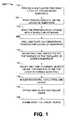
- FIG. 1is a flowchart illustrating an exemplary vehicular safety device production method, according to a preferred embodiment of the present invention
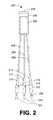
- FIG. 2is a top plan view illustrating an exemplary vehicular safety device, according to a preferred embodiment of the present invention
- FIGS. 3A and 3Bare perspective views of an exemplary ground wire connector for connecting the vehicular safety device to vehicle ground, according to a preferred embodiment of the present invention
- FIG. 3Cis a schematic diagram of the vehicular safety device depicted in FIG. 2 ;
- FIG. 4is a process chart view, illustrating an exemplary installation process for the exemplary vehicular safety device of FIG. 2 , according to a preferred embodiment of the present invention
- FIG. 5is a time vs. intensity graph illustrating two exemplary illumination patterns of the exemplary vehicular safety device of FIG. 2 , according to a preferred embodiment of the present invention
- FIG. 6is a time vs. intensity graph illustrating two exemplary illumination patterns of a second embodiment of the exemplary vehicular safety device of FIG. 2 , according to a preferred embodiment of the present invention.
- FIG. 7is a time vs. intensity graph illustrating two exemplary illumination patterns of a third embodiment the exemplary vehicular safety device of FIG. 2 , according to a preferred embodiment of the present invention.
- FIG. 1is a flowchart 100 illustrating an exemplary method for producing a vehicular safety device 200 (shown in FIG. 2 ), according to a preferred embodiment of the present invention.
- the methodbegins with providing 102 a multi-layer printable circuit board substrate.
- the multi-layer printable circuit boardis printed 104 as one board and then cut into sections (layers) one-half inch wide and 1.2 inches long.
- each layeris separately printed 104 .
- the layersare bonded 106 , as is known in the art of circuit board manufacture, to form a multi-plane circuit board. Seven vias are then drilled and plated 108 to form inter-plane connections. Once the production of the bare board is complete, components are added to the bare board.
- CMOS IC 232(shown in FIG. 3C ) is mounted on the top surface of the printed circuit board.
- the CMOS ICis preferably a CD4060BC CMOS IC, which is a 14-stage ripple binary counter IC.
- P-Channel MOSFET 234(shown in FIG. 3C ) is mounted on the top surface of the printed circuit board.
- the MOSFETis preferably a TCP8114. In additional embodiments, other P-channel MOSFETS may be used.
- resistors, capacitors, and diodesare added to the circuit board. Steps 110 , 112 , and 114 may be performed in any order, or intermixed, or done all at once, or done at once for the top of the circuit board and at once for the bottom of the circuit board.
- three leads 208 , 206 , 204(shown in FIGS. 2 and 3C ) (red, yellow, and black, respectively) are attached to the circuit board and the circuit board is covered 118 with a shrink wrapping.
- FIG. 2is a diagrammatic view illustrating an exemplary vehicular safety device 200 , according to a preferred embodiment of the present invention, produced in accordance with the method described with reference to FIG. 1 .
- Vehicular safety device 200comprises a circuit board 230 electrically connected to three leads 204 , 206 , and 208 (black, yellow, and red, respectively) and covered by a shrink wrap 202 .
- Black lead 204has a crimpable connector 226 .
- a sleeve 210 and a cover 216slide on black lead 204 to cover at least a portion of the crimped connection after installation.
- Yellow lead 206has a crimpable connector 224 .
- a sleeve 212 and a cover 218slide on yellow lead 206 to cover at least a portion of the crimped connection after installation.
- Red lead 208has a crimpable connector 222 .
- a sleeve 214 and a cover 220slide on red lead 208 to cover at least a portion of the crimped connection after installation.
- Vehicular safety device 200further comprises a coupling portion 228 , such as a hook or loop section of a hook and loop fastener, for attaching vehicular safety device 200 to the inside of the vehicle.
- FIGS. 3A and 3Bare perspective views of an exemplary ground wire connector 300 for connecting vehicular safety device 200 to a ground of the vehicle, according to a preferred embodiment of the present invention.
- Ground wire connector 300comprises two sides 302 , 304 and clamps 306 , 308 and 310 therebetween. Clamps 306 and 308 are shown on FIG. 3A and clamp 310 is shown in FIG. 3B , which depicts an opposite side of the view of exemplary ground wire connector 300 shown in FIG. 3A .
- the ground wire in the vehicleis severed and the ends are stripped and preferably inserted in clamps 306 and 310 .
- Sides 302 and 304may open hingedly to facilitate this clamping.
- Black lead crimpable connector 226is preferably inserted in clamp 308 , giving the black lead 204 an electrical connection to ground.
- ground wire connector 300may be of various types having equivalent functionality.
- FIG. 4is a flowchart illustrating an exemplary process 400 for the installation of vehicular safety device 200 , according to a preferred embodiment of the present invention.
- step 402the vehicular safety device 200 ; the installation instructions; and a wire stripper, wire cutter, and crimper (which three may be the same tool), are gathered together.
- step 404the installer verifies that the engine and lights are off.
- step 406physical access to the CHMSL is obtained.
- step 408the ground wire in the vehicle and within the CHMSL housing is severed and the ends are stripped and inserted in clamps 306 and 310 . Sides 302 and 304 may open hingedly to facilitate this clamping.
- Black lead crimpable connector 226is inserted in clamp 308 , giving the black lead 204 an electrical connection to ground.
- the power lead (wire) going to and within the CHMSL from the brake switch 320 (shown in FIG. 3C )is severed 410 and the ends stripped and crimpable connector 222 is crimped 412 onto the lead 208 ′ leading to the brake switch 320 and crimpable connector 224 is crimped 414 onto the end of the brake light wire 208 ′′ of the brake light 330 (shown in FIG. 3C ) within the CHMSL housing and leading to the CHMSL.
- the vehicular safety device 200is then attached 416 to a wall or other surface within the vehicle cavity holding the CHMSL using a coupling portion 228 that is either generic, such as hook and loop fasteners, or that is specifically designed for the particular vehicle cavity. Access to the CHMSL housing is closed 418 and the tools put away in step 420 .
- FIG. 5is a time vs. intensity graph 500 illustrating two exemplary illumination patterns 510 and 512 of the exemplary vehicular safety device 200 of FIG. 2 , according to a preferred embodiment of the present invention.
- the output of one embodiment of the vehicular safety device 200are illumination patterns 510 and 512 of various amounts of power to produce various intensities of light from the CHMSL.
- Four intensity levelsare shown: the highest intensity 508 is the highest intensity at which the CHMSL can be operated.
- a middle intensity 506not used in the embodiment graphed in FIG. 5 , is above the minimum visible intensity 504 and below the highest intensity 508 .
- the intensity level 502indicates that the CHMSL is off.
- each illumination pattern 510 and 512consists of three high intensity outputs 522 having periods 516 (one of six labeled) interlaced between lower intensity outputs 524 having periods 514 .
- Each period 514 and 516must be longer than one-thirtieth of a second and is preferably longer than one-tenth of a second.
- the lower intensity CHMSL output 524is preferably slightly higher than the minimum visible level 504 , as shown.
- the higher intensity CHMSL output 522is preferably equal to the highest intensity level 508 , as shown.
- Each illumination pattern 510 and 512is separated by an interval 518 that varies depending on the driver's use of the brake pedal. Each illumination pattern 510 and 512 begins when the driver steps on the brake pedal.
- interval 518can be thought of as potentially negative, i.e., if the driver pumps the brakes during illumination pattern 510 , then illumination pattern 512 will start immediately, replacing the remainder of illumination pattern 510 .
- each illumination pattern 510 and 512may have more or fewer high intensity outputs 522 and more or fewer low intensity outputs 524 .
- periods 514 and 516may not be of equal duration.
- the illumination pattern 510 or 512may begin with the higher intensity output 522 rather than the lower intensity output 524 .
- FIG. 6is a time vs. intensity graph 600 illustrating two exemplary illumination patterns 610 and 612 of a second embodiment of the exemplary vehicular safety device 200 of FIG. 2 , according to a preferred embodiment of the present invention.
- Illumination patterns 610 and 612use a middle intensity output 626 (one of six labeled) in between high intensity output 622 and low intensity output 624 .
- high intensity output 622 duration 616is preferably longer than either the middle intensity output 626 duration 620 or the low intensity output 624 duration 614 .
- Interval 618 between illumination patterns 610 and 612depends on the driver's use, with the illumination pattern 610 or 612 beginning each time the brake pedal is depressed, regardless of whether or not an earlier illumination pattern is still in progress.
- FIG. 6shows three visible levels of output 622 , 624 , and 626
- the inventionis not limited to any particular number of intensity levels, within the constraint that the duration of each intensity output is preferably greater than or equal to one-tenth of a second.
- One novelty of this embodimentis having more than two visible intensity levels 622 , 624 , and 626 .
- FIG. 7is a time vs. intensity graph illustrating two exemplary illumination patterns 710 and 712 of a third embodiment 700 the exemplary vehicular safety device 200 of FIG. 2 , according to a preferred embodiment of the present invention.
- graph 700shows three visible intensity levels: low 724 , middle 726 , and highest 722 .
- high intensity outputs 728 , 730 , and 732Within a illumination pattern 710 , there are three high intensity outputs 728 , 730 , and 732 .
- High intensity output periods 716are not equal, nor are the middle intensity output periods 720 (one of five in illumination pattern 712 labeled), nor the low intensity output periods 714 (one of four labeled).
- a novelty of this embodimentis that output periods 716 , 714 , and 720 may not be equal to each other, giving the light output a distinctive difference from the prior art.
- Another novel aspect of the inventionis that no two sequential illumination patterns 710 and 712 are the same, due to the variation in output periods 716 , 714 , and 720 in each illumination pattern 710 and 712 . Intensities and durations may be uncorrelated. As a result, observing drivers do not get desensitized to the light output, as they do when looking at the same thing over and over again.
- the vehicular safety devicemay be integrated into a vehicle's electronics system during manufacture.
Landscapes
- Engineering & Computer Science (AREA)
- Mechanical Engineering (AREA)
- Lighting Device Outwards From Vehicle And Optical Signal (AREA)
Abstract
Description
Claims (3)
Priority Applications (1)
| Application Number | Priority Date | Filing Date | Title |
|---|---|---|---|
| US14/275,864US9592763B2 (en) | 2013-05-13 | 2014-05-12 | Vehicular safety assistive device |
Applications Claiming Priority (2)
| Application Number | Priority Date | Filing Date | Title |
|---|---|---|---|
| US201361822741P | 2013-05-13 | 2013-05-13 | |
| US14/275,864US9592763B2 (en) | 2013-05-13 | 2014-05-12 | Vehicular safety assistive device |
Publications (2)
| Publication Number | Publication Date |
|---|---|
| US20140333426A1 US20140333426A1 (en) | 2014-11-13 |
| US9592763B2true US9592763B2 (en) | 2017-03-14 |
Family
ID=51864374
Family Applications (1)
| Application Number | Title | Priority Date | Filing Date |
|---|---|---|---|
| US14/275,864ActiveUS9592763B2 (en) | 2013-05-13 | 2014-05-12 | Vehicular safety assistive device |
Country Status (1)
| Country | Link |
|---|---|
| US (1) | US9592763B2 (en) |
Cited By (1)
| Publication number | Priority date | Publication date | Assignee | Title |
|---|---|---|---|---|
| US10766408B2 (en) | 2016-02-29 | 2020-09-08 | Safely Brake, Inc. | Safety brake light module and method of engaging a safety brake light |
Citations (34)
| Publication number | Priority date | Publication date | Assignee | Title |
|---|---|---|---|---|
| US3576527A (en) | 1968-06-10 | 1971-04-27 | Bendix Corp | Safety alert for automobile brake systems |
| US3740715A (en) | 1970-10-19 | 1973-06-19 | Rexroth & Szekkessy | Circuit system for brake lights |
| US3760353A (en) | 1971-10-18 | 1973-09-18 | Dv Displays Corp | Emergency vehicular warning system |
| US3846749A (en) | 1973-02-01 | 1974-11-05 | Massachusetts Inst Technology | Vehicle brake light control system |
| US3914739A (en) | 1972-01-31 | 1975-10-21 | James Daniel Caughlin | Vehicle brake and indicator light control system |
| US4403210A (en) | 1982-01-29 | 1983-09-06 | P. Sully Co. | Brake light enhancer circuit |
| US4651129A (en) | 1985-05-03 | 1987-03-17 | Bac-Off Corporation | Motor vehicle rear light assembly |
| US4876525A (en) | 1988-02-22 | 1989-10-24 | Sylvia Gross | Emergency warning brake system |
| US4956633A (en) | 1989-11-14 | 1990-09-11 | Dr. Fernald Wentzell | Break light enhancer with fail safe protection |
| US4983952A (en) | 1990-01-10 | 1991-01-08 | Improved Performance Systems, Inc. | Brake actuated flashing light system for a motor vehicle |
| US4987405A (en) | 1990-06-04 | 1991-01-22 | Jakobowski Walter T | Elevated brake light signal module |
| US5001398A (en)* | 1989-07-03 | 1991-03-19 | Motorola, Inc. | Lamp intensity control system having over-current protection |
| US5028908A (en) | 1990-04-24 | 1991-07-02 | Juang Ing Bin | Control circuit for vehicle taillights |
| US5172095A (en) | 1991-11-04 | 1992-12-15 | Scott Terrell L | Vehicle deceleration alert system |
| US5231373A (en)* | 1991-06-28 | 1993-07-27 | William H. Freeman | Multi-level illumination control system for automotive signalling use |
| US5345218A (en) | 1992-08-31 | 1994-09-06 | Woods Daniel S | Flashing brake light system |
| US5404130A (en) | 1991-04-12 | 1995-04-04 | Lee; Dong H. | Sudden-stop brake-light warning system |
| US5442333A (en) | 1991-02-22 | 1995-08-15 | Scott Allan Pitcher | Urgent braking device |
| US5565841A (en) | 1994-12-02 | 1996-10-15 | Pandohie; Sobas R. | Brake light perception enhancement system |
| US5606310A (en) | 1995-09-26 | 1997-02-25 | Egger; Christopher M. | Safety braking control for a vehicle that is responsive to hard braking by a driver of the vehicle |
| US5677670A (en) | 1995-07-20 | 1997-10-14 | Gangloff; Rodney W. | Flashing brake light apparatus |
| US5847513A (en) | 1995-10-16 | 1998-12-08 | Host; Rudolph P. | Automotive high mount brake light improvement |
| US5909174A (en) | 1996-03-20 | 1999-06-01 | Mercedes-Benz Ag | Control device, especially for vehicle braking light control |
| US6025775A (en)* | 1997-06-26 | 2000-02-15 | Erlandson; Glenn E. | Driving-safety ancillary white-flash alerting-system |
| US6111500A (en)* | 1998-10-20 | 2000-08-29 | Wilson; James Hoover | Automatic brakes initiated annunciator |
| US6160476A (en) | 1997-04-21 | 2000-12-12 | Itt Manufacturing Enterprises, Inc. | Method and system for providing an optical signal at the rear of a vehicle to warn the driver of a following vehicle |
| US6175305B1 (en) | 1994-12-20 | 2001-01-16 | Louis E. Johnson | Stoplamp modulator module electronic device |
| US20030164035A1 (en)* | 2002-03-01 | 2003-09-04 | Lear Corporation | Tire pressure monitoring system with low frequency initiation approach |
| US6693526B1 (en) | 2003-06-04 | 2004-02-17 | Gasper P. Puccio | Brake light system for a vehicle |
| US6710709B1 (en) | 2000-04-03 | 2004-03-23 | Louis F. Morin | Motor vehicle safety lights |
| US6720871B2 (en) | 2000-12-20 | 2004-04-13 | Transalert, Inc. | Modulated intensity flasher for vehicle brake light with lockout |
| US6744361B1 (en) | 2001-12-10 | 2004-06-01 | Harold Maddox | Vehicular safety brake light system |
| US20100066528A1 (en) | 2008-09-16 | 2010-03-18 | Kim Peter P | Automatic flashing brake lights and associated method |
| US20110181197A1 (en)* | 2007-08-07 | 2011-07-28 | Rohm Co., Ltd. | Light source turn-on/off controller |
- 2014
- 2014-05-12USUS14/275,864patent/US9592763B2/enactiveActive
Patent Citations (35)
| Publication number | Priority date | Publication date | Assignee | Title |
|---|---|---|---|---|
| US3576527A (en) | 1968-06-10 | 1971-04-27 | Bendix Corp | Safety alert for automobile brake systems |
| US3740715A (en) | 1970-10-19 | 1973-06-19 | Rexroth & Szekkessy | Circuit system for brake lights |
| US3760353A (en) | 1971-10-18 | 1973-09-18 | Dv Displays Corp | Emergency vehicular warning system |
| US3914739A (en) | 1972-01-31 | 1975-10-21 | James Daniel Caughlin | Vehicle brake and indicator light control system |
| US3846749A (en) | 1973-02-01 | 1974-11-05 | Massachusetts Inst Technology | Vehicle brake light control system |
| US4403210A (en) | 1982-01-29 | 1983-09-06 | P. Sully Co. | Brake light enhancer circuit |
| US4651129A (en) | 1985-05-03 | 1987-03-17 | Bac-Off Corporation | Motor vehicle rear light assembly |
| US4876525A (en) | 1988-02-22 | 1989-10-24 | Sylvia Gross | Emergency warning brake system |
| US5001398A (en)* | 1989-07-03 | 1991-03-19 | Motorola, Inc. | Lamp intensity control system having over-current protection |
| US4956633A (en) | 1989-11-14 | 1990-09-11 | Dr. Fernald Wentzell | Break light enhancer with fail safe protection |
| US4983952A (en) | 1990-01-10 | 1991-01-08 | Improved Performance Systems, Inc. | Brake actuated flashing light system for a motor vehicle |
| US5028908A (en) | 1990-04-24 | 1991-07-02 | Juang Ing Bin | Control circuit for vehicle taillights |
| US4987405A (en) | 1990-06-04 | 1991-01-22 | Jakobowski Walter T | Elevated brake light signal module |
| US5442333A (en) | 1991-02-22 | 1995-08-15 | Scott Allan Pitcher | Urgent braking device |
| US5404130A (en) | 1991-04-12 | 1995-04-04 | Lee; Dong H. | Sudden-stop brake-light warning system |
| US5231373A (en)* | 1991-06-28 | 1993-07-27 | William H. Freeman | Multi-level illumination control system for automotive signalling use |
| US5172095A (en) | 1991-11-04 | 1992-12-15 | Scott Terrell L | Vehicle deceleration alert system |
| US5345218A (en) | 1992-08-31 | 1994-09-06 | Woods Daniel S | Flashing brake light system |
| US5565841A (en) | 1994-12-02 | 1996-10-15 | Pandohie; Sobas R. | Brake light perception enhancement system |
| US6175305B1 (en) | 1994-12-20 | 2001-01-16 | Louis E. Johnson | Stoplamp modulator module electronic device |
| US5677670A (en) | 1995-07-20 | 1997-10-14 | Gangloff; Rodney W. | Flashing brake light apparatus |
| US5606310A (en) | 1995-09-26 | 1997-02-25 | Egger; Christopher M. | Safety braking control for a vehicle that is responsive to hard braking by a driver of the vehicle |
| US5847513A (en) | 1995-10-16 | 1998-12-08 | Host; Rudolph P. | Automotive high mount brake light improvement |
| US5909174A (en) | 1996-03-20 | 1999-06-01 | Mercedes-Benz Ag | Control device, especially for vehicle braking light control |
| US6160476A (en) | 1997-04-21 | 2000-12-12 | Itt Manufacturing Enterprises, Inc. | Method and system for providing an optical signal at the rear of a vehicle to warn the driver of a following vehicle |
| US6025775A (en)* | 1997-06-26 | 2000-02-15 | Erlandson; Glenn E. | Driving-safety ancillary white-flash alerting-system |
| US6111500A (en)* | 1998-10-20 | 2000-08-29 | Wilson; James Hoover | Automatic brakes initiated annunciator |
| US6710709B1 (en) | 2000-04-03 | 2004-03-23 | Louis F. Morin | Motor vehicle safety lights |
| US6720871B2 (en) | 2000-12-20 | 2004-04-13 | Transalert, Inc. | Modulated intensity flasher for vehicle brake light with lockout |
| US6943677B2 (en) | 2000-12-20 | 2005-09-13 | Transalert, Inc. | Modulated intensity flasher for vehicle brake light with lockout |
| US6744361B1 (en) | 2001-12-10 | 2004-06-01 | Harold Maddox | Vehicular safety brake light system |
| US20030164035A1 (en)* | 2002-03-01 | 2003-09-04 | Lear Corporation | Tire pressure monitoring system with low frequency initiation approach |
| US6693526B1 (en) | 2003-06-04 | 2004-02-17 | Gasper P. Puccio | Brake light system for a vehicle |
| US20110181197A1 (en)* | 2007-08-07 | 2011-07-28 | Rohm Co., Ltd. | Light source turn-on/off controller |
| US20100066528A1 (en) | 2008-09-16 | 2010-03-18 | Kim Peter P | Automatic flashing brake lights and associated method |
Cited By (2)
| Publication number | Priority date | Publication date | Assignee | Title |
|---|---|---|---|---|
| US10766408B2 (en) | 2016-02-29 | 2020-09-08 | Safely Brake, Inc. | Safety brake light module and method of engaging a safety brake light |
| US11305687B2 (en) | 2016-02-29 | 2022-04-19 | Safely Brake, Inc. | Safety brake light module and method of engaging a safety brake light |
Also Published As
| Publication number | Publication date |
|---|---|
| US20140333426A1 (en) | 2014-11-13 |
Similar Documents
| Publication | Publication Date | Title |
|---|---|---|
| US7172315B2 (en) | LED lamp assembly | |
| US10351050B1 (en) | Emergency or work related light bar | |
| CN103269907B (en) | Wire harness assembly and lighting unit | |
| US7154387B2 (en) | Vehicle deceleration warning system | |
| US20180119904A1 (en) | Light bar | |
| US4663609A (en) | Brake alert device | |
| US5606309A (en) | Road hazard warning apparatus | |
| CN2402549Y (en) | Double-circuit car safety belt automatic warning device | |
| JP6108648B2 (en) | Vehicle brake lighting | |
| US20190217769A1 (en) | Rear Light Safety System | |
| DE602006014728D1 (en) | PROCESS FOR PREVENTING ACCIDENTS CAUSED BY PASSING VEHICLES | |
| US20140218190A1 (en) | Brake intensity light display | |
| US11299090B2 (en) | Remote lighting system operable to correspond with vehicle lighting | |
| US9592763B2 (en) | Vehicular safety assistive device | |
| US20050274050A1 (en) | Moving condition display apparatus for a vehicle | |
| US20070109113A1 (en) | Vehicle signaling system | |
| US20040175249A1 (en) | Lighted tie down anchor and method for using same | |
| US6111500A (en) | Automatic brakes initiated annunciator | |
| JP2739325B2 (en) | Display body | |
| KR100537660B1 (en) | U-turn indication device of automobile | |
| US20070132574A1 (en) | Pre-braking warning device for vehicles | |
| CN2546272Y (en) | Automobile safety belt warning device | |
| GB2232259A (en) | Vehicle socket tester | |
| JP2791561B2 (en) | Accelerator operation degree display device | |
| HUP0302394A2 (en) | Automatic signaling device for automobiles |
Legal Events
| Date | Code | Title | Description |
|---|---|---|---|
| AS | Assignment | Owner name:BRAKEPLUS, LLC, ARIZONA Free format text:ASSIGNMENT OF ASSIGNORS INTEREST;ASSIGNOR:CHRISTIAN, RON;REEL/FRAME:033165/0832 Effective date:20130912 Owner name:EVANS, RICHARD W., INDIANA Free format text:SECURITY INTEREST;ASSIGNOR:BRAKE PLUS, LLC;REEL/FRAME:033224/0783 Effective date:20130913 | |
| AS | Assignment | Owner name:EVANS, RICHARD W., INDIANA Free format text:ASSIGNMENT OF ASSIGNORS INTEREST;ASSIGNOR:BRAKEPLUS, LLC;REEL/FRAME:033323/0025 Effective date:20140716 | |
| AS | Assignment | Owner name:SAFELY BRAKE. INC., INDIANA Free format text:ASSIGNMENT OF ASSIGNORS INTEREST;ASSIGNOR:EVANS, RICHARD W.;REEL/FRAME:035407/0789 Effective date:20150408 | |
| STCF | Information on status: patent grant | Free format text:PATENTED CASE | |
| MAFP | Maintenance fee payment | Free format text:PAYMENT OF MAINTENANCE FEE, 4TH YR, SMALL ENTITY (ORIGINAL EVENT CODE: M2551); ENTITY STATUS OF PATENT OWNER: SMALL ENTITY Year of fee payment:4 | |
| MAFP | Maintenance fee payment | Free format text:PAYMENT OF MAINTENANCE FEE, 8TH YR, SMALL ENTITY (ORIGINAL EVENT CODE: M2552); ENTITY STATUS OF PATENT OWNER: SMALL ENTITY Year of fee payment:8 |