US9592029B2 - Vascular access monitoring device - Google Patents
Vascular access monitoring deviceDownload PDFInfo
- Publication number
- US9592029B2 US9592029B2US13/393,429US201013393429AUS9592029B2US 9592029 B2US9592029 B2US 9592029B2US 201013393429 AUS201013393429 AUS 201013393429AUS 9592029 B2US9592029 B2US 9592029B2
- Authority
- US
- United States
- Prior art keywords
- vascular access
- patient
- ultrasonic
- transmitter
- skin
- Prior art date
- Legal status (The legal status is an assumption and is not a legal conclusion. Google has not performed a legal analysis and makes no representation as to the accuracy of the status listed.)
- Active, expires
Links
- 230000002792vascularEffects0.000titleclaimsabstractdescription37
- 238000012806monitoring deviceMethods0.000titleclaimsabstractdescription13
- 238000002604ultrasonographyMethods0.000claimsabstractdescription27
- 238000012544monitoring processMethods0.000claimsabstractdescription6
- 239000012528membraneSubstances0.000claimsdescription25
- 230000008878couplingEffects0.000claimsdescription19
- 238000010168coupling processMethods0.000claimsdescription19
- 238000005859coupling reactionMethods0.000claimsdescription19
- 238000001704evaporationMethods0.000claimsdescription14
- 230000008020evaporationEffects0.000claimsdescription12
- 230000005540biological transmissionEffects0.000claimsdescription8
- XLYOFNOQVPJJNP-UHFFFAOYSA-NwaterSubstancesOXLYOFNOQVPJJNP-UHFFFAOYSA-N0.000claimsdescription8
- 238000004092self-diagnosisMethods0.000claimsdescription4
- 238000004891communicationMethods0.000claimsdescription3
- 230000001808coupling effectEffects0.000claimsdescription3
- 239000000463materialSubstances0.000claimsdescription3
- 230000003292diminished effectEffects0.000claimsdescription2
- 238000000034methodMethods0.000claimsdescription2
- 238000001228spectrumMethods0.000claims1
- 238000011282treatmentMethods0.000abstractdescription4
- 239000000499gelSubstances0.000description36
- 238000000502dialysisMethods0.000description5
- 239000002184metalSubstances0.000description5
- 239000008280bloodSubstances0.000description4
- 210000004369bloodAnatomy0.000description4
- 239000003814drugSubstances0.000description4
- 229940079593drugDrugs0.000description4
- 210000001519tissueAnatomy0.000description3
- 239000012530fluidSubstances0.000description2
- 238000001631haemodialysisMethods0.000description2
- 230000000322hemodialysisEffects0.000description2
- 238000000968medical method and processMethods0.000description2
- 239000000203mixtureSubstances0.000description2
- 230000000422nocturnal effectEffects0.000description2
- 230000002035prolonged effectEffects0.000description2
- 238000010521absorption reactionMethods0.000description1
- 230000006978adaptationEffects0.000description1
- 210000000988bone and boneAnatomy0.000description1
- 230000015556catabolic processEffects0.000description1
- 230000001010compromised effectEffects0.000description1
- 238000006731degradation reactionMethods0.000description1
- 238000003745diagnosisMethods0.000description1
- 238000010586diagramMethods0.000description1
- 230000003670easy-to-cleanEffects0.000description1
- 230000000694effectsEffects0.000description1
- 229920002457flexible plasticPolymers0.000description1
- 230000001939inductive effectEffects0.000description1
- 238000001802infusionMethods0.000description1
- 238000003780insertionMethods0.000description1
- 230000037431insertionEffects0.000description1
- 230000003287optical effectEffects0.000description1
- 238000004806packaging method and processMethods0.000description1
- 238000012545processingMethods0.000description1
Images


Classifications
- A—HUMAN NECESSITIES
- A61—MEDICAL OR VETERINARY SCIENCE; HYGIENE
- A61B—DIAGNOSIS; SURGERY; IDENTIFICATION
- A61B8/00—Diagnosis using ultrasonic, sonic or infrasonic waves
- A61B8/42—Details of probe positioning or probe attachment to the patient
- A61B8/4209—Details of probe positioning or probe attachment to the patient by using holders, e.g. positioning frames
- A61B8/4227—Details of probe positioning or probe attachment to the patient by using holders, e.g. positioning frames characterised by straps, belts, cuffs or braces
- A—HUMAN NECESSITIES
- A61—MEDICAL OR VETERINARY SCIENCE; HYGIENE
- A61B—DIAGNOSIS; SURGERY; IDENTIFICATION
- A61B8/00—Diagnosis using ultrasonic, sonic or infrasonic waves
- A61B8/08—Clinical applications
- A61B8/0833—Clinical applications involving detecting or locating foreign bodies or organic structures
- A61B8/0841—Clinical applications involving detecting or locating foreign bodies or organic structures for locating instruments
- A—HUMAN NECESSITIES
- A61—MEDICAL OR VETERINARY SCIENCE; HYGIENE
- A61M—DEVICES FOR INTRODUCING MEDIA INTO, OR ONTO, THE BODY; DEVICES FOR TRANSDUCING BODY MEDIA OR FOR TAKING MEDIA FROM THE BODY; DEVICES FOR PRODUCING OR ENDING SLEEP OR STUPOR
- A61M1/00—Suction or pumping devices for medical purposes; Devices for carrying-off, for treatment of, or for carrying-over, body-liquids; Drainage systems
- A61M1/36—Other treatment of blood in a by-pass of the natural circulatory system, e.g. temperature adaptation, irradiation ; Extra-corporeal blood circuits
- A61M1/3621—Extra-corporeal blood circuits
- A61M1/3653—Interfaces between patient blood circulation and extra-corporal blood circuit
- A61M1/3656—Monitoring patency or flow at connection sites; Detecting disconnections
- A—HUMAN NECESSITIES
- A61—MEDICAL OR VETERINARY SCIENCE; HYGIENE
- A61M—DEVICES FOR INTRODUCING MEDIA INTO, OR ONTO, THE BODY; DEVICES FOR TRANSDUCING BODY MEDIA OR FOR TAKING MEDIA FROM THE BODY; DEVICES FOR PRODUCING OR ENDING SLEEP OR STUPOR
- A61M1/00—Suction or pumping devices for medical purposes; Devices for carrying-off, for treatment of, or for carrying-over, body-liquids; Drainage systems
- A61M1/36—Other treatment of blood in a by-pass of the natural circulatory system, e.g. temperature adaptation, irradiation ; Extra-corporeal blood circuits
- A61M1/3621—Extra-corporeal blood circuits
- A61M1/3653—Interfaces between patient blood circulation and extra-corporal blood circuit
- A61M1/3659—Cannulae pertaining to extracorporeal circulation
- A—HUMAN NECESSITIES
- A61—MEDICAL OR VETERINARY SCIENCE; HYGIENE
- A61M—DEVICES FOR INTRODUCING MEDIA INTO, OR ONTO, THE BODY; DEVICES FOR TRANSDUCING BODY MEDIA OR FOR TAKING MEDIA FROM THE BODY; DEVICES FOR PRODUCING OR ENDING SLEEP OR STUPOR
- A61M5/00—Devices for bringing media into the body in a subcutaneous, intra-vascular or intramuscular way; Accessories therefor, e.g. filling or cleaning devices, arm-rests
- A61M5/14—Infusion devices, e.g. infusing by gravity; Blood infusion; Accessories therefor
- A61M5/168—Means for controlling media flow to the body or for metering media to the body, e.g. drip meters, counters ; Monitoring media flow to the body
- A61M5/16831—Monitoring, detecting, signalling or eliminating infusion flow anomalies
- A61M5/16836—Monitoring, detecting, signalling or eliminating infusion flow anomalies by sensing tissue properties at the infusion site, e.g. for detecting infiltration
- A—HUMAN NECESSITIES
- A61—MEDICAL OR VETERINARY SCIENCE; HYGIENE
- A61B—DIAGNOSIS; SURGERY; IDENTIFICATION
- A61B5/00—Measuring for diagnostic purposes; Identification of persons
- A61B5/0002—Remote monitoring of patients using telemetry, e.g. transmission of vital signals via a communication network
- A—HUMAN NECESSITIES
- A61—MEDICAL OR VETERINARY SCIENCE; HYGIENE
- A61B—DIAGNOSIS; SURGERY; IDENTIFICATION
- A61B5/00—Measuring for diagnostic purposes; Identification of persons
- A61B5/02—Detecting, measuring or recording for evaluating the cardiovascular system, e.g. pulse, heart rate, blood pressure or blood flow
- A61B5/02042—Determining blood loss or bleeding, e.g. during a surgical procedure
- A—HUMAN NECESSITIES
- A61—MEDICAL OR VETERINARY SCIENCE; HYGIENE
- A61B—DIAGNOSIS; SURGERY; IDENTIFICATION
- A61B8/00—Diagnosis using ultrasonic, sonic or infrasonic waves
- A61B8/08—Clinical applications
- A61B8/0891—Clinical applications for diagnosis of blood vessels
- A—HUMAN NECESSITIES
- A61—MEDICAL OR VETERINARY SCIENCE; HYGIENE
- A61B—DIAGNOSIS; SURGERY; IDENTIFICATION
- A61B8/00—Diagnosis using ultrasonic, sonic or infrasonic waves
- A61B8/42—Details of probe positioning or probe attachment to the patient
- A61B8/4272—Details of probe positioning or probe attachment to the patient involving the acoustic interface between the transducer and the tissue
- A61B8/4281—Details of probe positioning or probe attachment to the patient involving the acoustic interface between the transducer and the tissue characterised by sound-transmitting media or devices for coupling the transducer to the tissue
- A—HUMAN NECESSITIES
- A61—MEDICAL OR VETERINARY SCIENCE; HYGIENE
- A61B—DIAGNOSIS; SURGERY; IDENTIFICATION
- A61B8/00—Diagnosis using ultrasonic, sonic or infrasonic waves
- A61B8/44—Constructional features of the ultrasonic, sonic or infrasonic diagnostic device
- A61B8/4444—Constructional features of the ultrasonic, sonic or infrasonic diagnostic device related to the probe
- A61B8/4472—Wireless probes
- A—HUMAN NECESSITIES
- A61—MEDICAL OR VETERINARY SCIENCE; HYGIENE
- A61M—DEVICES FOR INTRODUCING MEDIA INTO, OR ONTO, THE BODY; DEVICES FOR TRANSDUCING BODY MEDIA OR FOR TAKING MEDIA FROM THE BODY; DEVICES FOR PRODUCING OR ENDING SLEEP OR STUPOR
- A61M2205/00—General characteristics of the apparatus
- A61M2205/13—General characteristics of the apparatus with means for the detection of operative contact with patient, e.g. lip sensor
- A—HUMAN NECESSITIES
- A61—MEDICAL OR VETERINARY SCIENCE; HYGIENE
- A61M—DEVICES FOR INTRODUCING MEDIA INTO, OR ONTO, THE BODY; DEVICES FOR TRANSDUCING BODY MEDIA OR FOR TAKING MEDIA FROM THE BODY; DEVICES FOR PRODUCING OR ENDING SLEEP OR STUPOR
- A61M2205/00—General characteristics of the apparatus
- A61M2205/33—Controlling, regulating or measuring
- A61M2205/3375—Acoustical, e.g. ultrasonic, measuring means
- A—HUMAN NECESSITIES
- A61—MEDICAL OR VETERINARY SCIENCE; HYGIENE
- A61M—DEVICES FOR INTRODUCING MEDIA INTO, OR ONTO, THE BODY; DEVICES FOR TRANSDUCING BODY MEDIA OR FOR TAKING MEDIA FROM THE BODY; DEVICES FOR PRODUCING OR ENDING SLEEP OR STUPOR
- A61M5/00—Devices for bringing media into the body in a subcutaneous, intra-vascular or intramuscular way; Accessories therefor, e.g. filling or cleaning devices, arm-rests
- A61M5/14—Infusion devices, e.g. infusing by gravity; Blood infusion; Accessories therefor
- A61M5/168—Means for controlling media flow to the body or for metering media to the body, e.g. drip meters, counters ; Monitoring media flow to the body
- A61M5/16831—Monitoring, detecting, signalling or eliminating infusion flow anomalies
Definitions
- This inventionrelates to vascular access monitoring, in particular it relates to a device and method for monitoring for the presence of a needle or cannular to determine if it becomes dislodged from a patient.
- a dislodged needlecan cause serious medical consequences, for example dislodgement of a needle providing life supporting drugs, if not detected could even result in death, as could dislodgement of a blood return needle in a hemodialysis treatment whereby the dialyser can pull blood from the body but not return it. This is especially dangerous in overnight dialysis while the patent is asleep as they would not see the blood escaping.
- a monitoring device for monitoring the presence of a skin piercing vascular access devicecomprising:
- the deviceperiodically emits an ultrasonic pulse and receives the reflected ultrasonic signal.
- the vascular access devicee.g. a needle
- the vascular access devicee.g. a needle
- control electronicsmonitor the received signal received within in a particular time window, that time window being based on a maximum and minimum expected time of flight of the ultrasonic pulse from the transmitter, to the needle and back to the receiver.
- windowexceeds the expected window by a factor relating to a margin of error.
- the senoris configured to identify ultrasonic reflections from first and second surfaces, one of which is the needle, and the sensor detects a change in the received signals.
- the second surfaceis a deeper part of the body, e.g. a bone.
- the amplitude of the reflected signalchanges dependant on the presence of the vascular access device.
- an ultrasonic gelis used between the device and the patients skin to effectively ultrasonically couple the device to the patient.
- this coupling gelmay be applied directly to the skin.
- the devicefurther comprises a thin flexible gel pack, comprising an ultrasonic coupling gel, encapsulated within a flexible membrane, for insertion between the device and the skin.
- a thin flexible gel packcomprising an ultrasonic coupling gel, encapsulated within a flexible membrane, for insertion between the device and the skin.
- the gel packhas a thin flexible outer membrane that conforms easily to the skin thereby, in use, conforming to the contours of the patient's skin.
- the flexible outer membraneprevents the ultrasonic coupling gel, which is usually water based, from evaporating over time. While normal gels applied to the skin are very useful for short term use, in some applications such as nocturnal dialysis, it may be necessary to monitor for dislodgement of the needle over a prolonged period of time, the water base of the ultrasonic gel will evaporate and eventually ultrasonic coupling may be lost resulting in false alarms. By encapsulating the ultrasonic gel in a thin pack the evaporation can be prevented or minimised, thereby overcoming the problem of gel evaporation.
- the attachment meanscomprises a strap to pass around a section of the patients body, for example an arm.
- the deviceis provided with an electrical connection for connecting the device to a medical apparatus, for example a dialysis machine.
- the devicehas a wireless transceiver for connection to a medical apparatus. In this manner, if dislodgement of the vascular access device is sensed then this can be transmitted to the medical apparatus which can take appropriate action, i.e. it may sound a warning or stop an automated medical process.
- the devicehas control electronics configured to periodically receive an interrogation from a medical apparatus to do a self diagnosis check, to carry out a self diagnosis check and to send a signal to the medical apparatus indicative that the diagnosis check was successful and the device is working properly.
- the ultrasonic transmitteris a piezo transmitter.
- the transmitter and receivercomprise a single transceiver.
- the devicefurther comprises a power source.
- the power sourceis a re-chargeable battery and more preferably the re-chargeable battery is wirelessly re-chargeable and is fully encapsulated within the device. In this manner the device can easily be sanitised between uses.
- a thin flexible gel packfor use with the device of the first aspect of the invention, comprising:
- the gel packcomprises two planar sides of flexible membrane material joined around their edges to encapsulate the gel therein.
- the thin flexible gelis inserted between the device and the skin to ultrasonically couple the device to the patient's skin.
- the flexible membraneprevents the ultrasonic coupling gel, which is usually water based, from evaporating over time. While normal gels applied to the skin are very useful for short term use, in some applications such as nocturnal dialysis, it may be necessary to monitor for dislodgement of the needle over a prolonged period of time, the water base of the ultrasonic gel will evaporate and eventually ultrasonic coupling may be lost resulting in false alarms.
- the ultrasonic gelBy encapsulating the ultrasonic gel in a thin pack the evaporation can be prevented or minimised, thereby overcoming the problem of gel evaporation.
- the gel packhas a thin flexible outer membrane that conforms easily to the skin thereby, in use, conforming to the contours of the patient's skin.
- the gel packhas characteristics specific to the device for which it is intended to be used with.
- the flexible membranehas a thickness is equal to, or less than one third of the wavelength of the ultrasound transmitted from the device.
- the composition of the gelis such that it has an optimum transmission frequency substantially that of the transmission frequency of the device with which it is intended to be used. More preferably it is composed to have an optimum transmission frequency in the range of 100 kHz to 2 MHz.
- the flexible membraneprevents evaporation of water therethrough.
- the flexible membraneis semi permeable, and permits the slow evaporation of water therethrough.
- the gel packis provided in a sealed outer package, the outer package preventing evaporation from the gel. More preferably the membrane retards evaporation such after removal from the outer package the gel pack retains sufficient gel therein to function for at least 12 hours before its ultrasonic coupling properties become diminished.
- the ultrasonic coupling properties of the gel packcan be allowed to diminish over time. Therefore, if the outer packaging becomes compromised, for example in transit, and the gel will slowly evaporate such that by the time it is used it should not function. Also, as the packs are a consumable part, near a skin puncture site, it is advantageous to provide a necessity for it to be changed on a time basis, and also that the pads can not be re-used from one patient to another. The time based degradation discourages such re-use.
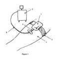
- FIG. 1is a perspective view of one embodiment of the device in use
- FIG. 2is a cross section through same embodiment of the device in use.
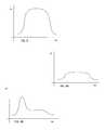
- FIGS. 3, 4A and 4Bare diagrams of ultrasonic signals.
- FIG. 3is shows a typical ultrasonic pulse emitted by the device.
- FIG. 4Ashows a typical reflection of the ultrasonic pulse by the patient's body when a metal needle is not present
- FIG. 4Bshows a typical reflection of the ultrasonic pulse when a metal needle is present.
- the device 1is shown attached to a patient's arm 2 by means of an attachment strap 3 .
- the device 1is located adjacent the entry point of a needle 4 which is connected to a medical apparatus 5 by means of a conduit 6 .
- the medical apparatus 5can be used to either add fluid to or remove fluid from the patient via the needle 4 .
- FIG. 2a cross section through the device in use is shown.
- the device 1is positioned adjacent a patients arm 2 and between the patent's arm 2 and the device 1 is a thin gel pack 7 which comprises an ultrasonic coupling gel in a thin flexible plastic pouch.
- the gel pack 7conforms to the surface of the patient's arm 2 and to the device 1 such that the space between the patients arm 2 and the device 1 is substantially filled with ultrasonic coupling gel.
- an ultrasonic transceiver 8transmits an ultrasonic pulse through the gel pack and into the patient's arm 2 .
- the gel pack 7has walls made of a flexible membrane that has a thickness less than one third of the wavelength of the ultrasound transmitted from the device and the composition of the gel is such that it has an optimum transmission frequency substantially that of the transmission frequency of the device.
- the patient's armwill absorb some of the ultrasonic signal and reflect some of the signal.
- the transceiveralso receives the reflected signal.
- the transceiveris connected to control electronics 10 which control the transmitter to transmit ultrasound and receive signals indicative of the received reflected signal from the transceiver 8 .
- the control electronicsthen compare the received signal, either to the transmitted signal or to a model signal stores in storage means 9 connected to the control electronics 10 to detect if it shows characteristics relating to absorption and reflection by the patient's arm 2 , or if it also shows characteristics relating to reflection by a needle 4 .
- Signals relating to a needle 4will be clearly distinguishable from signals relating to just the patients body as a needle 4 , in particular a metal needle as is commonly used, will reflect a much greater amount of ultrasound.
- the control deviceis powered by a battery 11 which is encapsulated within the device 1 .
- the batterymay be recharged by an inductive recharger. In this way the battery can be recharged without needing to open the device to remove the battery. Furthermore, as the device is totally encapsulated it is easy to clean and/or sanitise between uses.
- the device 1further comprises a wireless communications module 12 by which the device can wirelessly communication with the control system of a medical apparatus.
- a wireless communications module 12by which the device can wirelessly communication with the control system of a medical apparatus.
- the device 1senses it and sends a signal t the medical apparatus to which the needle 4 is connected. He apparatus can then take appropriate action, for example it may sound a warning and/or may stop the medical process using the needle. For example, if the needle is being used to infuse drugs into a patient then if the needle 4 becomes dislodged then the medical apparatus can sound a warning to alert a nurse and can also stop the dispense of drugs through the needle 4 .
- FIGS. 3, 4A and 4Bsignal comparisons typical of those used in the device are shown.
- FIG. 3shows a typical ultrasonic pulse emitted by the device.
- FIGS. 4A and 4Bshow two signals, one in FIG. 4A relating to the reflection of ultrasound by the patient's body when a metal needle is not present and the other in FIG. 4B showing how this changes when a metal needle is present.
- the control electronicscan compare the shape of the received signals and easily identify whether there is a needle present or not.
- the wireless connectioncould be replaced with a wires connection and the battery could be replaced with a connection to a remote power source.
Landscapes
- Health & Medical Sciences (AREA)
- Life Sciences & Earth Sciences (AREA)
- Heart & Thoracic Surgery (AREA)
- Engineering & Computer Science (AREA)
- Biomedical Technology (AREA)
- Vascular Medicine (AREA)
- Veterinary Medicine (AREA)
- Animal Behavior & Ethology (AREA)
- General Health & Medical Sciences (AREA)
- Public Health (AREA)
- Hematology (AREA)
- Anesthesiology (AREA)
- Cardiology (AREA)
- Radiology & Medical Imaging (AREA)
- Surgery (AREA)
- Molecular Biology (AREA)
- Medical Informatics (AREA)
- Physics & Mathematics (AREA)
- Pathology (AREA)
- Nuclear Medicine, Radiotherapy & Molecular Imaging (AREA)
- Biophysics (AREA)
- Ultra Sonic Daignosis Equipment (AREA)
- Infusion, Injection, And Reservoir Apparatuses (AREA)
- External Artificial Organs (AREA)
Abstract
Description
- a mount having an ultrasonic transmitter and an ultrasonic receiver therein;
- attachment means for attaching the mount to a patient adjacent a vascular access point such that, in use, a vascular access device entering the patient at the vascular access point, passes underneath a sensing section of the base;
- a control circuit to monitor the signal received at the receiver, and wherein
- when the vascular access device is underneath said sensing section, ultrasound produced by said transmitter passes through the patient skin and is reflected by the patients body tissues and by the vascular access device, and
- when the vascular access device is not underneath said sensing section, ultrasound produced by said transmitter passes through the patients skin and is reflected by the patients body tissue only, and wherein
- the control electronics detects the presence of a vascular access device by performing a comparison on the received ultrasonic signal.
- an ultrasonic coupling gel, encapsulated within a flexible membrane and wherein the flexible membrane allows the passage of ultrasound therethrough.
Claims (30)
Applications Claiming Priority (3)
| Application Number | Priority Date | Filing Date | Title |
|---|---|---|---|
| GB0910467.0 | 2009-06-18 | ||
| GBGB0910467.0AGB0910467D0 (en) | 2009-06-18 | 2009-06-18 | Vascular access monitoring device |
| PCT/GB2010/001202WO2010146372A2 (en) | 2009-06-18 | 2010-06-18 | Vascular access monitoring device |
Publications (2)
| Publication Number | Publication Date |
|---|---|
| US20120271160A1 US20120271160A1 (en) | 2012-10-25 |
| US9592029B2true US9592029B2 (en) | 2017-03-14 |
Family
ID=45840713
Family Applications (1)
| Application Number | Title | Priority Date | Filing Date |
|---|---|---|---|
| US13/393,429Active2031-04-30US9592029B2 (en) | 2009-06-18 | 2010-06-18 | Vascular access monitoring device |
Country Status (2)
| Country | Link |
|---|---|
| US (1) | US9592029B2 (en) |
| EP (1) | EP2442851B1 (en) |
Cited By (7)
| Publication number | Priority date | Publication date | Assignee | Title |
|---|---|---|---|---|
| US10433790B2 (en) | 2015-09-25 | 2019-10-08 | C. R. Bard, Inc. | Catheter assembly including monitoring capabilities |
| US11305040B2 (en) | 2014-04-29 | 2022-04-19 | Outset Medical, Inc. | Dialysis system and methods |
| US11534537B2 (en) | 2016-08-19 | 2022-12-27 | Outset Medical, Inc. | Peritoneal dialysis system and methods |
| US11724013B2 (en) | 2010-06-07 | 2023-08-15 | Outset Medical, Inc. | Fluid purification system |
| US11992292B2 (en) | 2020-01-07 | 2024-05-28 | Bard Access Systems, Inc. | Diagnostic systems and methods including temperature-sensing vascular devices |
| US12201762B2 (en) | 2018-08-23 | 2025-01-21 | Outset Medical, Inc. | Dialysis system and methods |
| US12390565B2 (en) | 2019-04-30 | 2025-08-19 | Outset Medical, Inc. | Dialysis systems and methods |
Families Citing this family (5)
| Publication number | Priority date | Publication date | Assignee | Title |
|---|---|---|---|---|
| US8152751B2 (en) | 2007-02-09 | 2012-04-10 | Baxter International Inc. | Acoustic access disconnection systems and methods |
| AU2013201556B2 (en) | 2012-07-13 | 2014-06-05 | Gambro Lundia Ab | Filtering of pressure signals for suppression of periodic pulses |
| DE102013008720B4 (en)* | 2013-05-23 | 2019-05-09 | Fresenius Medical Care Deutschland Gmbh | Method and device for monitoring extracorporeal blood circulation |
| CA3188633A1 (en)* | 2020-07-02 | 2022-01-06 | Fresenius Medical Care Holdings, Inc. | System and method for detecting venous needle dislodgement |
| WO2025090713A1 (en) | 2023-10-27 | 2025-05-01 | Fresenius Medical Care Holdings, Inc. | Needle dislodgement detection systems and methods |
Citations (55)
| Publication number | Priority date | Publication date | Assignee | Title |
|---|---|---|---|---|
| US3921622A (en)* | 1973-02-27 | 1975-11-25 | Edward Michael Cole | Method and apparatus for ultrasonic detection of inclusions in a flowing fluid |
| US3972320A (en)* | 1974-08-12 | 1976-08-03 | Gabor Ujhelyi Kalman | Patient monitoring system |
| US4205686A (en)* | 1977-09-09 | 1980-06-03 | Picker Corporation | Ultrasonic transducer and examination method |
| EP0121931A2 (en) | 1983-04-11 | 1984-10-17 | Ivac Corporation | Fault detection apparatus for parenteral infusion system |
| US4648869A (en) | 1985-12-04 | 1987-03-10 | American Hospital Supply Corporation | Automatic infiltration detection system and method |
| US4710163A (en) | 1986-06-06 | 1987-12-01 | Ivac Corporation | Detection of fluid flow faults in the parenteral administration of fluids |
| US4771792A (en) | 1985-02-19 | 1988-09-20 | Seale Joseph B | Non-invasive determination of mechanical characteristics in the body |
| EP0328163A2 (en) | 1983-04-11 | 1989-08-16 | Ivac Corporation | Fault detection apparatus for parenteral infusion system and method of detecting faults in such a system |
| EP0330761A1 (en) | 1988-02-27 | 1989-09-06 | Fresenius AG | Method for measuring and indicating in liquid systems of medical devices, and device for carrying out this method |
| EP0332330A2 (en) | 1988-03-08 | 1989-09-13 | BAXTER INTERNATIONAL INC. (a Delaware corporation) | Automatic infiltration detection system |
| EP0361793A2 (en) | 1988-09-26 | 1990-04-04 | Baxter International Inc. | An In-Line infiltration detection apparatus and method |
| WO1991000113A2 (en) | 1989-06-22 | 1991-01-10 | Baxter International Inc. | Infusion system, methodology, and algorithm for identifying patient-induced pressure artifacts |
| US5095910A (en) | 1990-04-18 | 1992-03-17 | Advanced Technology Laboratories, Inc. | Ultrasonic imaging of biopsy needle |
| WO1997010013A1 (en) | 1995-09-12 | 1997-03-20 | Gambro Ab | Method and arrangement for detecting the condition of a blood vessel access |
| DE19609698A1 (en) | 1996-03-13 | 1997-09-18 | Metrax Gmbh | Blood pressure and pulse rate measuring apparatus |
| US5727550A (en)* | 1996-04-09 | 1998-03-17 | Lectec Corporation | Dual purpose ultrasonic biomedical couplant pad and electrode |
| EP0895787A1 (en) | 1997-08-06 | 1999-02-10 | Fresenius Medical Care Deutschland GmbH | Method for monitoring a blood vessel access during a dialysis treatment and apparatus for dialysis treatment with a device for monitoring a blood vessel access |
| US5882300A (en)* | 1996-11-07 | 1999-03-16 | Spacelabs Medical, Inc. | Wireless patient monitoring apparatus using inductive coupling |
| WO1999029356A1 (en) | 1997-12-05 | 1999-06-17 | Meier Peter F | Method and device for monitoring a catheter unit |
| DE19802985A1 (en) | 1998-01-28 | 1999-07-29 | Torsten Dr Siepmann | Sensor to monitor position of catheter in patient's body |
| DE19848235C1 (en) | 1998-10-20 | 2000-03-16 | Fresenius Medical Care De Gmbh | Method for monitoring supply to vessel and extra-corporeal blood treatment device for monitoring supply to vessel; inputs blood circulation pressure to computer to calculate values to identify errors in supply during dialysis |
| US6132378A (en)* | 1998-08-10 | 2000-10-17 | Marino; Sharon | Cover for ultrasound probe |
| US6216029B1 (en) | 1995-07-16 | 2001-04-10 | Ultraguide Ltd. | Free-hand aiming of a needle guide |
| US20030128125A1 (en) | 2002-01-04 | 2003-07-10 | Burbank Jeffrey H. | Method and apparatus for machine error detection by combining multiple sensor inputs |
| US20030126910A1 (en) | 2002-01-04 | 2003-07-10 | Burbank Jeffrey H. | Method and apparatus for leak detection in blood circuits combining external fluid detection and air infiltration detection |
| US6626832B1 (en)* | 1999-04-15 | 2003-09-30 | Ultraguide Ltd. | Apparatus and method for detecting the bending of medical invasive tools in medical interventions |
| EP1472973A1 (en) | 2003-04-28 | 2004-11-03 | Nemoto Kyorindo Co., Ltd. | Leak detector using pulse signals |
| US20050010118A1 (en) | 2003-07-10 | 2005-01-13 | Nikkiso Co. Ltd. | Method and device for measuring pulse rate, blood pressure, and monitoring blood vessel access |
| JP2005040518A (en) | 2003-07-25 | 2005-02-17 | Toin Gakuen | Access trouble detection system in dialysis |
| US20050038325A1 (en) | 2003-08-13 | 2005-02-17 | Bradley Jon Moll, Rodney L. Moll And Anne E. Moll Family Trust | Method and device for monitoring loss of body fluid and dislodgment of medical instrument from body |
| US20070016053A1 (en)* | 2005-06-08 | 2007-01-18 | Lo Thomas Y | Ultrasonic monitor with an adhesive member |
| US20070073155A1 (en) | 2005-09-02 | 2007-03-29 | Ultrasound Ventures, Llc | Ultrasound guidance system |
| US20070167808A1 (en) | 2005-12-09 | 2007-07-19 | Mitsuhiro Nozaki | Ultrasound probe for paracentesis and ultrasound diagnostic apparatus |
| US20080108930A1 (en) | 2006-11-03 | 2008-05-08 | The Regents Of The University Of Michigan | Methods and Systems for Determining Volume Flow in a Blood or Fluid Conduit, Motion, and Mechanical Properties of Structures Within the Body |
| US20080195021A1 (en)* | 2007-02-09 | 2008-08-14 | Baxter International Inc. | Acoustic access disconnection systems and methods |
| US20080195060A1 (en) | 2007-02-09 | 2008-08-14 | Baxter International Inc. | Optical access disconnection systems and methods |
| US20080221519A1 (en)* | 2005-06-10 | 2008-09-11 | Koninklijke Philips Electronics, N.V. | System for Guiding a Probe Over the Surface of the Skin of a Patient or an Animal |
| US20080275396A1 (en) | 2005-05-10 | 2008-11-06 | Koninklijke Philips Electronics, N.V. | Cannula Inserting System |
| WO2009024333A1 (en) | 2007-08-22 | 2009-02-26 | Fresenius Medical Care Deutschland Gmbh | Device and method for monitoring an access to a patient |
| US20090082649A1 (en)* | 2007-09-21 | 2009-03-26 | Baxter International Inc. | Access disconnect system with optical and other sensors |
| US20090082676A1 (en) | 2007-09-21 | 2009-03-26 | Baxter International Inc. | Acoustic access disconnect detection system |
| US20090088683A1 (en) | 2007-10-01 | 2009-04-02 | Baxter International Inc. | Adaptive algorithm for access disconnect detection |
| WO2010089130A1 (en) | 2009-02-06 | 2010-08-12 | Fresenius Medical Care Deutschland Gmbh | Device and method for exciting vibration of at least one segment of a vascular access device for monitoring the same |
| US20100234786A1 (en) | 2009-02-12 | 2010-09-16 | Barry Neil Fulkerson | System and Method for Detection of Disconnection in an Extracorporeal Blood Circuit |
| US7874999B2 (en) | 2007-09-24 | 2011-01-25 | Baxter International, Inc. | Detecting access disconnect using needle sleeve |
| US8114043B2 (en) | 2008-07-25 | 2012-02-14 | Baxter International Inc. | Electromagnetic induction access disconnect sensor |
| US8137300B2 (en) | 2002-04-10 | 2012-03-20 | Baxter International Inc. | Access disconnection systems and methods using conductive contacts |
| US8192388B2 (en) | 2008-07-25 | 2012-06-05 | Baxter International Inc. | System and method for detecting access disconnection |
| US8221320B2 (en) | 2007-09-21 | 2012-07-17 | Baxter International Inc. | Access disconnect detection system |
| US8348850B2 (en) | 2001-07-30 | 2013-01-08 | Henry Ford Health System | Method of monitoring dislodgement of venous needles in dialysis patients |
| US8360977B2 (en) | 2007-09-27 | 2013-01-29 | Baxter International Inc. | Continuity circuits for detecting access disconnection |
| US8529490B2 (en) | 2002-04-10 | 2013-09-10 | Baxter International Inc. | Systems and methods for dialysis access disconnection |
| US8597505B2 (en) | 2007-09-13 | 2013-12-03 | Fresenius Medical Care Holdings, Inc. | Portable dialysis machine |
| US8974394B2 (en) | 2001-07-30 | 2015-03-10 | Henry Ford Health System | Device and method for detecting irregular placement of an extracorporeal vascular access needle |
| US9011334B2 (en) | 2007-09-27 | 2015-04-21 | Baxter International Inc. | Access disconnect detection |
- 2010
- 2010-06-18EPEP10760373.0Apatent/EP2442851B1/enactiveActive
- 2010-06-18USUS13/393,429patent/US9592029B2/enactiveActive
Patent Citations (70)
| Publication number | Priority date | Publication date | Assignee | Title |
|---|---|---|---|---|
| US3921622A (en)* | 1973-02-27 | 1975-11-25 | Edward Michael Cole | Method and apparatus for ultrasonic detection of inclusions in a flowing fluid |
| US3972320A (en)* | 1974-08-12 | 1976-08-03 | Gabor Ujhelyi Kalman | Patient monitoring system |
| US4205686A (en)* | 1977-09-09 | 1980-06-03 | Picker Corporation | Ultrasonic transducer and examination method |
| EP0121931A2 (en) | 1983-04-11 | 1984-10-17 | Ivac Corporation | Fault detection apparatus for parenteral infusion system |
| US4534756A (en) | 1983-04-11 | 1985-08-13 | Ivac Corporation | Fault detection apparatus and method for parenteral infusion system |
| EP0328163A2 (en) | 1983-04-11 | 1989-08-16 | Ivac Corporation | Fault detection apparatus for parenteral infusion system and method of detecting faults in such a system |
| US4771792A (en) | 1985-02-19 | 1988-09-20 | Seale Joseph B | Non-invasive determination of mechanical characteristics in the body |
| US4648869A (en) | 1985-12-04 | 1987-03-10 | American Hospital Supply Corporation | Automatic infiltration detection system and method |
| EP0232599A1 (en) | 1985-12-04 | 1987-08-19 | BAXTER INTERNATIONAL INC. (a Delaware corporation) | Automatic infiltration detection system |
| EP0248633A2 (en) | 1986-06-06 | 1987-12-09 | Ivac Corporation | Detection of fluid flow faults in the parenteral administration of fluids |
| US4710163A (en) | 1986-06-06 | 1987-12-01 | Ivac Corporation | Detection of fluid flow faults in the parenteral administration of fluids |
| EP0330761A1 (en) | 1988-02-27 | 1989-09-06 | Fresenius AG | Method for measuring and indicating in liquid systems of medical devices, and device for carrying out this method |
| EP0332330A2 (en) | 1988-03-08 | 1989-09-13 | BAXTER INTERNATIONAL INC. (a Delaware corporation) | Automatic infiltration detection system |
| EP0361793A2 (en) | 1988-09-26 | 1990-04-04 | Baxter International Inc. | An In-Line infiltration detection apparatus and method |
| WO1991000113A2 (en) | 1989-06-22 | 1991-01-10 | Baxter International Inc. | Infusion system, methodology, and algorithm for identifying patient-induced pressure artifacts |
| US5095910A (en) | 1990-04-18 | 1992-03-17 | Advanced Technology Laboratories, Inc. | Ultrasonic imaging of biopsy needle |
| US6216029B1 (en) | 1995-07-16 | 2001-04-10 | Ultraguide Ltd. | Free-hand aiming of a needle guide |
| WO1997010013A1 (en) | 1995-09-12 | 1997-03-20 | Gambro Ab | Method and arrangement for detecting the condition of a blood vessel access |
| DE19609698A1 (en) | 1996-03-13 | 1997-09-18 | Metrax Gmbh | Blood pressure and pulse rate measuring apparatus |
| US5727550A (en)* | 1996-04-09 | 1998-03-17 | Lectec Corporation | Dual purpose ultrasonic biomedical couplant pad and electrode |
| US5882300A (en)* | 1996-11-07 | 1999-03-16 | Spacelabs Medical, Inc. | Wireless patient monitoring apparatus using inductive coupling |
| EP0895787A1 (en) | 1997-08-06 | 1999-02-10 | Fresenius Medical Care Deutschland GmbH | Method for monitoring a blood vessel access during a dialysis treatment and apparatus for dialysis treatment with a device for monitoring a blood vessel access |
| US6077443A (en) | 1997-08-06 | 2000-06-20 | Fresenius Medical Care Deutschland Gmbh | Method and device for monitoring a vascular access during a dialysis treatment |
| WO1999029356A1 (en) | 1997-12-05 | 1999-06-17 | Meier Peter F | Method and device for monitoring a catheter unit |
| DE19802985A1 (en) | 1998-01-28 | 1999-07-29 | Torsten Dr Siepmann | Sensor to monitor position of catheter in patient's body |
| US6132378A (en)* | 1998-08-10 | 2000-10-17 | Marino; Sharon | Cover for ultrasound probe |
| DE19848235C1 (en) | 1998-10-20 | 2000-03-16 | Fresenius Medical Care De Gmbh | Method for monitoring supply to vessel and extra-corporeal blood treatment device for monitoring supply to vessel; inputs blood circulation pressure to computer to calculate values to identify errors in supply during dialysis |
| US6626832B1 (en)* | 1999-04-15 | 2003-09-30 | Ultraguide Ltd. | Apparatus and method for detecting the bending of medical invasive tools in medical interventions |
| US8974394B2 (en) | 2001-07-30 | 2015-03-10 | Henry Ford Health System | Device and method for detecting irregular placement of an extracorporeal vascular access needle |
| US8348850B2 (en) | 2001-07-30 | 2013-01-08 | Henry Ford Health System | Method of monitoring dislodgement of venous needles in dialysis patients |
| US20030126910A1 (en) | 2002-01-04 | 2003-07-10 | Burbank Jeffrey H. | Method and apparatus for leak detection in blood circuits combining external fluid detection and air infiltration detection |
| US20030128125A1 (en) | 2002-01-04 | 2003-07-10 | Burbank Jeffrey H. | Method and apparatus for machine error detection by combining multiple sensor inputs |
| US7040142B2 (en) | 2002-01-04 | 2006-05-09 | Nxstage Medical, Inc. | Method and apparatus for leak detection in blood circuits combining external fluid detection and air infiltration detection |
| US8137300B2 (en) | 2002-04-10 | 2012-03-20 | Baxter International Inc. | Access disconnection systems and methods using conductive contacts |
| US8801646B2 (en) | 2002-04-10 | 2014-08-12 | Baxter International Inc. | Access disconnection systems with arterial and venous line conductive pathway |
| US8708946B2 (en) | 2002-04-10 | 2014-04-29 | Baxter International Inc. | Access disconnection systems using conductive contacts |
| US8529490B2 (en) | 2002-04-10 | 2013-09-10 | Baxter International Inc. | Systems and methods for dialysis access disconnection |
| EP1472973A1 (en) | 2003-04-28 | 2004-11-03 | Nemoto Kyorindo Co., Ltd. | Leak detector using pulse signals |
| US20050010118A1 (en) | 2003-07-10 | 2005-01-13 | Nikkiso Co. Ltd. | Method and device for measuring pulse rate, blood pressure, and monitoring blood vessel access |
| JP2005040518A (en) | 2003-07-25 | 2005-02-17 | Toin Gakuen | Access trouble detection system in dialysis |
| US20050038325A1 (en) | 2003-08-13 | 2005-02-17 | Bradley Jon Moll, Rodney L. Moll And Anne E. Moll Family Trust | Method and device for monitoring loss of body fluid and dislodgment of medical instrument from body |
| US20080275396A1 (en) | 2005-05-10 | 2008-11-06 | Koninklijke Philips Electronics, N.V. | Cannula Inserting System |
| US20070016053A1 (en)* | 2005-06-08 | 2007-01-18 | Lo Thomas Y | Ultrasonic monitor with an adhesive member |
| US20080221519A1 (en)* | 2005-06-10 | 2008-09-11 | Koninklijke Philips Electronics, N.V. | System for Guiding a Probe Over the Surface of the Skin of a Patient or an Animal |
| US20070073155A1 (en) | 2005-09-02 | 2007-03-29 | Ultrasound Ventures, Llc | Ultrasound guidance system |
| US20070167808A1 (en) | 2005-12-09 | 2007-07-19 | Mitsuhiro Nozaki | Ultrasound probe for paracentesis and ultrasound diagnostic apparatus |
| US20080108930A1 (en) | 2006-11-03 | 2008-05-08 | The Regents Of The University Of Michigan | Methods and Systems for Determining Volume Flow in a Blood or Fluid Conduit, Motion, and Mechanical Properties of Structures Within the Body |
| WO2008100671A1 (en) | 2007-02-09 | 2008-08-21 | Baxter International Inc. | Acoustic access disconnection systems and methods |
| US20080195021A1 (en)* | 2007-02-09 | 2008-08-14 | Baxter International Inc. | Acoustic access disconnection systems and methods |
| US20080195060A1 (en) | 2007-02-09 | 2008-08-14 | Baxter International Inc. | Optical access disconnection systems and methods |
| WO2009024333A1 (en) | 2007-08-22 | 2009-02-26 | Fresenius Medical Care Deutschland Gmbh | Device and method for monitoring an access to a patient |
| US8597505B2 (en) | 2007-09-13 | 2013-12-03 | Fresenius Medical Care Holdings, Inc. | Portable dialysis machine |
| US8197431B2 (en) | 2007-09-21 | 2012-06-12 | Baxter International Inc. | Acoustic access disconnect detection system |
| US8187184B2 (en) | 2007-09-21 | 2012-05-29 | Baxter International, Inc. | Access disconnect system with optical and other sensors |
| US8708908B2 (en) | 2007-09-21 | 2014-04-29 | Baxter International Inc. | Access disconnect detection system |
| US8221320B2 (en) | 2007-09-21 | 2012-07-17 | Baxter International Inc. | Access disconnect detection system |
| WO2009038834A1 (en) | 2007-09-21 | 2009-03-26 | Baxter International Inc. | Acoustic access disconnect detection system |
| US20090082676A1 (en) | 2007-09-21 | 2009-03-26 | Baxter International Inc. | Acoustic access disconnect detection system |
| US20090082649A1 (en)* | 2007-09-21 | 2009-03-26 | Baxter International Inc. | Access disconnect system with optical and other sensors |
| US7874999B2 (en) | 2007-09-24 | 2011-01-25 | Baxter International, Inc. | Detecting access disconnect using needle sleeve |
| US8696571B2 (en) | 2007-09-27 | 2014-04-15 | Baxter International Inc. | Continuity circuits for detecting access disconnection |
| US9011334B2 (en) | 2007-09-27 | 2015-04-21 | Baxter International Inc. | Access disconnect detection |
| US8360977B2 (en) | 2007-09-27 | 2013-01-29 | Baxter International Inc. | Continuity circuits for detecting access disconnection |
| US20090088683A1 (en) | 2007-10-01 | 2009-04-02 | Baxter International Inc. | Adaptive algorithm for access disconnect detection |
| US8192388B2 (en) | 2008-07-25 | 2012-06-05 | Baxter International Inc. | System and method for detecting access disconnection |
| US8114043B2 (en) | 2008-07-25 | 2012-02-14 | Baxter International Inc. | Electromagnetic induction access disconnect sensor |
| US8926544B2 (en) | 2008-07-25 | 2015-01-06 | Baxter International Inc. | System and method for detecting access disconnection |
| WO2010089130A1 (en) | 2009-02-06 | 2010-08-12 | Fresenius Medical Care Deutschland Gmbh | Device and method for exciting vibration of at least one segment of a vascular access device for monitoring the same |
| US8535522B2 (en) | 2009-02-12 | 2013-09-17 | Fresenius Medical Care Holdings, Inc. | System and method for detection of disconnection in an extracorporeal blood circuit |
| US20100234786A1 (en) | 2009-02-12 | 2010-09-16 | Barry Neil Fulkerson | System and Method for Detection of Disconnection in an Extracorporeal Blood Circuit |
Non-Patent Citations (1)
| Title |
|---|
| May 18, 2015 Office Action in connection with U.S. Appl. No. 13/393,438. |
Cited By (10)
| Publication number | Priority date | Publication date | Assignee | Title |
|---|---|---|---|---|
| US11724013B2 (en) | 2010-06-07 | 2023-08-15 | Outset Medical, Inc. | Fluid purification system |
| US11305040B2 (en) | 2014-04-29 | 2022-04-19 | Outset Medical, Inc. | Dialysis system and methods |
| US10433790B2 (en) | 2015-09-25 | 2019-10-08 | C. R. Bard, Inc. | Catheter assembly including monitoring capabilities |
| US11129573B2 (en) | 2015-09-25 | 2021-09-28 | C. R. Bard, Inc. | Catheter assembly including monitoring capabilities |
| US11826171B2 (en) | 2015-09-25 | 2023-11-28 | C. R. Bard, Inc. | Catheter assembly including monitoring capabilities |
| US11534537B2 (en) | 2016-08-19 | 2022-12-27 | Outset Medical, Inc. | Peritoneal dialysis system and methods |
| US11951241B2 (en) | 2016-08-19 | 2024-04-09 | Outset Medical, Inc. | Peritoneal dialysis system and methods |
| US12201762B2 (en) | 2018-08-23 | 2025-01-21 | Outset Medical, Inc. | Dialysis system and methods |
| US12390565B2 (en) | 2019-04-30 | 2025-08-19 | Outset Medical, Inc. | Dialysis systems and methods |
| US11992292B2 (en) | 2020-01-07 | 2024-05-28 | Bard Access Systems, Inc. | Diagnostic systems and methods including temperature-sensing vascular devices |
Also Published As
| Publication number | Publication date |
|---|---|
| EP2442851A2 (en) | 2012-04-25 |
| EP2442851B1 (en) | 2013-09-04 |
| US20120271160A1 (en) | 2012-10-25 |
Similar Documents
| Publication | Publication Date | Title |
|---|---|---|
| US9592029B2 (en) | Vascular access monitoring device | |
| EP2442725B1 (en) | Vascular access monitoring device | |
| WO2010146372A2 (en) | Vascular access monitoring device | |
| US8525643B2 (en) | Medical system with identification patch | |
| JP5589100B2 (en) | Optical access disconnection system | |
| JP5986608B2 (en) | Electrical heart rate access disconnection system | |
| US9549688B2 (en) | Implantable medical device detection | |
| US9782532B2 (en) | Apparatus and method for the vibratory stimulation of at least one portion of a vascular access device for its monitoring | |
| RU2753720C2 (en) | Observation device, probe for research and observation system | |
| WO1997006413A2 (en) | Disposable electromagnetic fluid level sensor | |
| KR102377682B1 (en) | Device for monitoring a vessel opening for an extracorporeal blood treatment device and method for monitoring a vessel opening | |
| US20140213939A1 (en) | Treatment apparatus for external application to a mammal body |
Legal Events
| Date | Code | Title | Description |
|---|---|---|---|
| AS | Assignment | Owner name:QUANTA FLUID SOLUTIONS LTD, UNITED KINGDOM Free format text:ASSIGNMENT OF ASSIGNORS INTEREST;ASSIGNOR:BUCKBERRY, CLIVE;REEL/FRAME:028522/0467 Effective date:20120611 | |
| AS | Assignment | Owner name:HERCULES CAPITAL, INC., CALIFORNIA Free format text:INTELLECTUAL PROPERTY SECURITY AGREEMENT;ASSIGNOR:QUANTA FLUID SOLUTIONS LIMITED;REEL/FRAME:038389/0395 Effective date:20160331 | |
| STCF | Information on status: patent grant | Free format text:PATENTED CASE | |
| AS | Assignment | Owner name:QUANTA DIALYSIS TECHNOLOGIES LIMITED, UNITED KINGDOM Free format text:CHANGE OF NAME;ASSIGNOR:QUANTA FLUID SOLUTIONS LTD;REEL/FRAME:046649/0810 Effective date:20160701 Owner name:QUANTA DIALYSIS TECHNOLOGIES LIMITED, UNITED KINGD Free format text:CHANGE OF NAME;ASSIGNOR:QUANTA FLUID SOLUTIONS LTD;REEL/FRAME:046649/0810 Effective date:20160701 | |
| AS | Assignment | Owner name:QUANTA DIALYSIS TECHNOLOGIES LIMITED, ENGLAND Free format text:RELEASE BY SECURED PARTY;ASSIGNOR:HERCULES CAPITAL, INC.;REEL/FRAME:051596/0970 Effective date:20191212 | |
| MAFP | Maintenance fee payment | Free format text:PAYMENT OF MAINTENANCE FEE, 4TH YR, SMALL ENTITY (ORIGINAL EVENT CODE: M2551); ENTITY STATUS OF PATENT OWNER: SMALL ENTITY Year of fee payment:4 | |
| MAFP | Maintenance fee payment | Free format text:PAYMENT OF MAINTENANCE FEE, 8TH YR, SMALL ENTITY (ORIGINAL EVENT CODE: M2552); ENTITY STATUS OF PATENT OWNER: SMALL ENTITY Year of fee payment:8 |