US9591434B1 - Virtual private network (VPN) tunneling in a user equipment (UE) brokered by a radio frequency identity (RFID) chip communicatively coupled to the user equipment - Google Patents
Virtual private network (VPN) tunneling in a user equipment (UE) brokered by a radio frequency identity (RFID) chip communicatively coupled to the user equipmentDownload PDFInfo
- Publication number
- US9591434B1 US9591434B1US14/696,835US201514696835AUS9591434B1US 9591434 B1US9591434 B1US 9591434B1US 201514696835 AUS201514696835 AUS 201514696835AUS 9591434 B1US9591434 B1US 9591434B1
- Authority
- US
- United States
- Prior art keywords
- rfid
- identity
- consumer electronic
- electronic device
- processor
- Prior art date
- Legal status (The legal status is an assumption and is not a legal conclusion. Google has not performed a legal analysis and makes no representation as to the accuracy of the status listed.)
- Active, expires
Links
- 230000005641tunnelingEffects0.000title1
- 238000004891communicationMethods0.000claimsabstractdescription112
- 230000015654memoryEffects0.000claimsabstractdescription97
- 230000001413cellular effectEffects0.000claimsabstractdescription14
- 238000000034methodMethods0.000claimsdescription26
- 238000010295mobile communicationMethods0.000claimsdescription18
- 238000013475authorizationMethods0.000claimsdescription12
- 238000012423maintenanceMethods0.000claimsdescription12
- 230000009471actionEffects0.000claimsdescription3
- 230000007774longtermEffects0.000claimsdescription3
- 230000010267cellular communicationEffects0.000claims1
- 238000003860storageMethods0.000description26
- LMESMTMYZUOGFN-STZQEDGTSA-Nram-388Chemical compoundC1C2=CC=C(OC)C(O)=C2[C@]23CCN(CCCCC)[C@H]1[C@]2(O)CCC(=O)C3LMESMTMYZUOGFN-STZQEDGTSA-N0.000description15
- 238000004590computer programMethods0.000description12
- 238000013461designMethods0.000description7
- 238000010586diagramMethods0.000description7
- 230000006870functionEffects0.000description6
- 238000012545processingMethods0.000description5
- 230000003287optical effectEffects0.000description4
- 230000002093peripheral effectEffects0.000description4
- 238000012797qualificationMethods0.000description4
- 230000004044responseEffects0.000description4
- 239000007787solidSubstances0.000description4
- 230000008569processEffects0.000description3
- 238000004883computer applicationMethods0.000description2
- 230000008878couplingEffects0.000description2
- 238000010168coupling processMethods0.000description2
- 238000005859coupling reactionMethods0.000description2
- 238000013500data storageMethods0.000description2
- 239000004973liquid crystal related substanceSubstances0.000description2
- 238000004519manufacturing processMethods0.000description2
- 230000007246mechanismEffects0.000description2
- 238000013515scriptMethods0.000description2
- 238000009987spinningMethods0.000description2
- 241000699670Mus sp.Species0.000description1
- 230000004075alterationEffects0.000description1
- 230000008859changeEffects0.000description1
- 238000013479data entryMethods0.000description1
- 238000011161developmentMethods0.000description1
- 238000009826distributionMethods0.000description1
- 230000009977dual effectEffects0.000description1
- 230000000694effectsEffects0.000description1
- 238000004870electrical engineeringMethods0.000description1
- 239000000835fiberSubstances0.000description1
- 230000003993interactionEffects0.000description1
- 238000007726management methodMethods0.000description1
- 230000006855networkingEffects0.000description1
- 238000009419refurbishmentMethods0.000description1
- 238000011160researchMethods0.000description1
- 230000000717retained effectEffects0.000description1
- 239000004065semiconductorSubstances0.000description1
- 230000003068static effectEffects0.000description1
- 238000006467substitution reactionMethods0.000description1
- 238000012546transferMethods0.000description1
- 230000001131transforming effectEffects0.000description1
Images


Classifications
- H04W4/008—
- H—ELECTRICITY
- H04—ELECTRIC COMMUNICATION TECHNIQUE
- H04L—TRANSMISSION OF DIGITAL INFORMATION, e.g. TELEGRAPHIC COMMUNICATION
- H04L63/00—Network architectures or network communication protocols for network security
- H04L63/02—Network architectures or network communication protocols for network security for separating internal from external traffic, e.g. firewalls
- H04L63/0272—Virtual private networks
- H—ELECTRICITY
- H04—ELECTRIC COMMUNICATION TECHNIQUE
- H04W—WIRELESS COMMUNICATION NETWORKS
- H04W12/00—Security arrangements; Authentication; Protecting privacy or anonymity
- H04W12/06—Authentication
- H—ELECTRICITY
- H04—ELECTRIC COMMUNICATION TECHNIQUE
- H04W—WIRELESS COMMUNICATION NETWORKS
- H04W4/00—Services specially adapted for wireless communication networks; Facilities therefor
- H04W4/80—Services using short range communication, e.g. near-field communication [NFC], radio-frequency identification [RFID] or low energy communication
Definitions
- UEsUser equipments
- a variety of computer applicationsmay execute on UEs providing gaming, navigation, search, media, and news services to the user of the UE.
- UEsmay be used as working tools by technicians and workmen.
- Functionality and/or applications on UEsmay be integrated with server applications that execute remotely from the UE.
- a user equipmentcomprising a motherboard comprising a communication bus, a cellular radio frequency transceiver connected to the communication bus of the motherboard, a processor connected to the communication bus of the motherboard, a radio frequency identity (RFID) chip connected to the communication bus of the motherboard, a memory connected to the communication bus of the motherboard, and an application stored in the memory.
- the RFID chipcomprises an RFID near field communication (NFC) transceiver, an RFID internal processor, an RFID internal memory, and an RFID application stored in the RFID internal memory, wherein the RFID chip provides wireless read access to the RFID internal memory and provides write access to the RFID internal memory to the communication bus of the motherboard.
- NFCnear field communication
- the applicationWhen executed by the processor, the application receives a request from the RFID chip to establish a virtual private network (VPN) tunnel via the cellular radio frequency transceiver based on information encapsulated in the request.
- the RFID applicationwhen executed by the RFID internal processor, receives a message from an NFC device via the RFID NFC transceiver, wherein the message comprises a command to open the VPN tunnel and, responsive to receiving the message from the NFC device, sends the request to establish the VPN tunnel to the application executed on the processor.
- VPNvirtual private network
- a method of servicing a consumer electronic devicecomprises receiving a near field communication (NFC) message from a mobile communication device, by a radio frequency identity (RFID) chip coupled to a motherboard of the consumer electronic device and, responsive to receiving the NFC message, sending by the RFID chip a request to a communication transceiver coupled to the motherboard to establish a virtual private network tunnel over an Internet to a cloud computing service.
- NFCnear field communication
- RFIDradio frequency identity
- the methodfurther comprises, responsive to the request from the RFID chip, establishing by the communication transceiver the VPN tunnel over the Internet to the cloud computing service and transmitting by the communication transceiver consumer electronic device information to the cloud computing service via the VPN tunnel, wherein the device information comprises an identity of the device, user settings of the device, and current state of the device, whereby the consumer electronic device information is made available to the mobile communication device via the cloud computing service for use by a technician to maintain the consumer electronic device.
- a memory devicecomprises a memory media, a communication bus, an memory reader communicatively coupled to a communication bus, and a radio frequency transceiver coupled to the communication bus.
- the memory devicefurther comprises a radio frequency identity (RFID) chip coupled to the communication bus and a processor coupled to the communication bus.
- RFID chipcomprises an RFID near field communication (NFC) transceiver, an RFID internal processor, an RFID internal memory, and an RFID application stored in the RFID local memory, wherein the RFID internal memory stores an identity of a paired computing device.
- NFCRFID near field communication
- the processoris operable to receive a request to read data from the memory media from the radio frequency transceiver, to request authorization from the RFID chip, to read data from the memory media via the memory reader, and to transmit the read data via the radio frequency transceiver.
- the RFID applicationreceives an identity from an external device, compares the identity of the external device to the identity of the paired computing device stored in the RFID internal memory, and responsive to agreement between the identity of the external device and the identity of the paired computing device stored in the RFID internal memory and responsive to the authorization request from the processor sends authorization to the processor.
- FIG. 1is a block diagram of a communication system according to an embodiment of the disclosure.
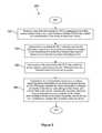
- FIG. 2is a flow chart of a method according to an embodiment of the disclosure.
- FIG. 3is a block diagram of a disk drive memory device according to an embodiment of the disclosure.
- FIG. 4is an illustration of a user equipment (UE) according to an embodiment of the disclosure.
- FIG. 5is a block diagram of a hardware architecture for a UE according to an embodiment of the disclosure.
- FIG. 6Ais a block diagram of a software architecture for a UE according to an embodiment of the disclosure.
- FIG. 6Bis a block diagram of another software architecture for a UE according to an embodiment of the disclosure.
- FIG. 7is a block diagram of a computer system according to an embodiment of the disclosure.
- the present disclosureteaches a radio frequency identity (RFID) chip coupled to the motherboard of a user equipment (UE) or mobile communication device (e.g., a mobile phone or smart phone) that promotes establishment of a virtual private network (VPN) tunnel between the user equipment and a content server or application server.
- RFIDradio frequency identity
- the RFID chip and UEmay establish a VPN tunnel to a content server to access privileged video or to a provisioning application server to configure communication service parameters of the UE in a retail store of a wireless communication service provider.
- the RFID chipmay provide an additional authentication factor in the establishment of the VPN tunnel, thereby reducing the risk of loss or expropriation of confidential and/or privileged information.
- this extra authentication factoris inherently linked to a qualifying location, due to the relatively short communication range of the RFID chip and an external reader/writer device that communicates with the RFID chip. Said in another way, the RFID chip introduces the opportunity to qualify the communication link—the VPN tunnel—based on a robust assurance of the current location of the UE.
- the security bar for deeming a UE as being worthy of extending a VPN tunnel tomay be lower if the system can be confident that the UE is located in a specific place, for example in a retail store of a wireless communication service provider. This inherent location qualification may be considered to be a quasi-third authentication factor.
- Such an inherent location qualificationalso may be said to be provided by the macro cellular radio transceiver of the UE, but it is to be noted that the location qualification of being in the coverage area of a known enhanced node B (i.e., a cellular tower) is a highly coarse grained location qualification relative to being in the coverage area of a near field communication (NFC) area of a RFID chip.
- a known enhanced node Bi.e., a cellular tower
- NFCnear field communication
- the RFID chipmay receive a request message from a near field communication (NFC) scanner (e.g., a kiosk in a retail store of a wireless communication service provider) via near field communications.
- NFCnear field communication
- the request messagerequests that the UE to which the RFID chip is coupled establish a VPN tunnel with a destination identified in the request message (e.g., a uniform resource locator (URL) or an Internet protocol (IP) address).
- the request messagefurther provides an authentication token.
- the RFID chipcommunicates with an application executing on a processor of the UE via a communication bus of the UE, communicating the request to open the VPN tunnel, the destination identification, and the authentication token.
- the application executing on the processor of the UEcommunicates with the destination node (e.g., a content server, an application server, a provisioning server, or the like) via a wireless communication link.
- the wireless communication linkmay be established using a cellular network or using a short range wireless communication protocol such as WiFi or Bluetooth.
- the applicationrequests a VPN tunnel from the destination node or from the communication network, providing an identity of the UE and providing the authentication token provided by the NFC scanner (e.g., the kiosk).
- the NFC scannertransmits the authentication token via a wired network to the destination node, and the destination node may compare the authentication token received from the UE with the authentication token received from the NFC scanner. If the authentication tokens match, the destination node can conclude that the UE is proximate to the NFC scanner (e.g., proximate to the kiosk and hence within the retail store of the service provider). This may be referred to as a first authentication factor.
- the destination nodemay further compare the identity of the UE against a list or data store of UEs that are provisioned to receive service from the service provider. If the UE is determined to be associated with a subscription account in good standing, this may be referred to as a second authentication factor. With the dual factor authentication completed, the destination node may establish the requested VPN tunnel.
- the RFID chipmay store a second authentication token locally, in the RFID chip, and may send this second authentication token to the application executing on the UE and to the NFC scanner.
- the NFC scannermay transmit this second authentication token to the destination node.
- the destination nodemay send a second VPN tunnel request to the UE carrying the second authentication token.
- the application executing on the processor of the UEmay compare the second authentication factor provided by the destination node to a local stored copy of the second authentication factor, and if the two authentication factors match, the UE may establish the VPN tunnel requested by the destination node as a second VPN tunnel.
- the first VPN tunnelmay be used for secure communication in one direction between the UE and the destination node while the second VPN tunnel may be used for secure communication in the opposite direction between the UE and the destination node.
- the UEmay be used by a service technician performing on-premises maintenance on a consumer electronic device, for example a large screen television.
- the UE of the service technicianfeatures an RFID chip as described above that communicates with an NFC radio transceiver (to some extent analogous to the kiosk in the above example).
- the RFID chip of the UEmay send a request to the NFC radio transceiver in the consumer electronic device.
- the consumer electronic devicesends data up to be stored in a cloud storage location along with an authentication token.
- the NFC radio transceiver of the consumer electronic devicesends the authentication token to the UE of the service technician.
- the UE of the service technicianmay then request the information stored in the cloud via an application server mediating access to the stored information, providing the authentication token in this request.
- the application servercompares the authentication tokens, and when they match, retrieves the information from the consumer electronic device stored in the cloud and transmits this information to the UE of the service technician, and the service technician may maintain the consumer electronic device, at least in part, based on the information presented on a display of the UE. After transmitting the information, the application server may delete the information from the cloud storage.
- the consumer electronic device informationmay comprise one or more of a history or log of previous maintenance actions performed on the consumer electronic device, an error log or fault log created by the device, user configuration settings of the device, user service subscriptions associated with the device (e.g., premium content services), premium service authentication tokens, a manufacturer identity (e.g., a ‘make’ or maker of the device), a device model identity, a device serial number, a device software version identity, and the like.
- the NFC communicationas a result of the communication range limitations inherent in NFC communications, contributes an element of security as the information exchanged over NFC cannot readily be intercepted, for example by devices lurking outside the residence, for example in a car parked on the street outside the residence. While the RFID chip contemplated by the present disclosure may be capable of transmitting and receiving over distances of about 15 feet of less, this range is still largely inconsistent from interception at a distance.
- the RFID chipmay be embedded in a hard disk memory drive.
- the hard disk drivemay desirably be paired with a unique computer via a wireless communication link. Should the hard disk drive be separated from the paired computer (e.g., the disk drive is left behind, lost, or stolen) it is desirable that the drive not be accessible or interoperable with a different computer.
- the unique pairingmay be established and maintained by a corresponding RFID chip in the computer, or another NFC transceiver peripheral coupled to the computer, where the two RFID chips periodically handshake with each other, for example sharing secret keys. When the handshake does not occur for a threshold period of time, the disk drive may deny requests to read or write the memory of the disk drive. It is understood that the functionality described with reference to a disk memory device is contemplated to be applicable to another form of mass storage device, such as a solid state mass storage device.
- the system 100comprises a user equipment (UE) 102 , a near field communication (NFC) scanner 104 , an enhanced node B (eNB) 106 , a network 108 , a content data store ( 110 ), and an application server 112 .
- the eNB 106provides a wireless communication link to the UE 102 according to one or more of a long term evolution (LTE), a code division multiple access (CDMA), a global system for mobile communication (GSM), or a worldwide interoperability for microwave access (WiMAX) wireless communication protocol.
- LTElong term evolution
- CDMAcode division multiple access
- GSMglobal system for mobile communication
- WiMAXworldwide interoperability for microwave access
- the eNB 106provides communication coupling to the network 108 , via a wireless link to the UE 102 and a wired or wireless link from the eNB 106 to the network 108 .
- the network 108comprises one or more of a private network, one or more of a public network, or a combination thereof.
- the UE 102may be a mobile phone, a smart phone, a media player, a media player, a headset computer, a wearable computer, a laptop computer, a notebook computer, or a tablet computer. It is understood that the system 100 may comprise any number of UEs 102 , eNBs 106 , NFC scanners 104 , content data stores 110 , and application servers 112 .
- the UE 102comprises a cellular radio transceiver 116 , a processor 118 , a memory 120 , a radio frequency identity (RFID) chip 124 , a communication bus 125 , and a motherboard 126 .
- the UE 102may comprise a short range radio transceiver (not shown) such as a WiFi radio transceiver and/or a Bluetooth® radio transceiver for establishing wireless communication links with an access point (not shown) and there through to the network 108 .
- the cellular radio transceiver 116 , the processor 118 , the memory 120 , and the RFID chip 124may communicate with each other via the communication bus 125 .
- the cellular radio transceiver 116 , the processor 118 , the memory 120 , the RFID chip 124 , and the communication bus 125may be mechanically secured by the motherboard 126 and retained within a package (e.g., an exterior) of the UE 102 . It is understood that the UE 102 also comprises a user interface such as a touchscreen display and control keys. Other details of an embodiment of a UE are described further hereinafter with reference to FIGS. 4, 5, 6A, and 6B .
- the memory 120may store an application 122 that, when executed by the processor 118 , may promote establishment of VPN tunnels and/or performing authentications with remote nodes or hosts, for example to establish a VPN tunnel to the application server 112 and/or to the content data store 110 . It is understood that the memory 120 may store a variety of other applications that may be executed by the processor 118 , both system applications installed by an original equipment manufacturer (OEM) of the UE 102 as well as user applications installed by a user of the UE 102 .
- System applicationsmay comprise applications such as an email application, a browser application, a contacts directory application, a dialer application (e.g., an application to promote establishing phone calls), a calendar application, and the like.
- User applicationsmay comprise a streaming media player application, a social networking application, a live news application, and the like.
- the RFID chip 124comprises an internal processor 128 , an internal memory 130 , and a near field communication (NFC) transceiver 132 .
- the internal memory 130may store a local application 134 that promotes mediating between the NFC scanner 104 and the application 122 , for example mediating establishment of a VPN tunnel from the UE 102 to the application server 112 and/or to the content data store 110 based on an authentication token received from and in response to a request message received from the NFC scanner 104 .
- the internal memory 130further stores at least a second authentication token 136 .
- the internal memory 130stores a plurality of “second” authentication tokens, a different “second” authentication token for each of a plurality of independent VPN tunnels that may be supported by the UE 102 .
- the internal memory 130may further store an identity of the UE 102 , for example a mobile equipment identity (MEID) and/or a phone number associated with the UE 102 .
- the internal processor 128may be referred to as an RFID internal processor
- the NFC transceiver 132may be referred to as an RFID NFC transceiver
- the internal memory 130may be referred to as an RFID internal memory
- the local application 134may be referred to as an RFID application.
- the NFC transceiver 132is configured to establish a wireless communication link using NFC communication protocols with an external NFC device, for example the NFC scanner 104 , over a range of about fifteen feet or less. In an embodiment, the NFC transceiver 132 is configured to establish a wireless communication link over a range of about five feet or less. In an embodiment, the NFC transceiver 132 is configured to establish a wireless communication link over a range of about two feet or less. The NFC transceiver 132 may conduct wireless communication with one or more antennas internal to the RFID chip 124 .
- the NFC transceiver 132may conduct wireless communication using an antenna external to the RFID chip 124 and located within the UE 102 , for example an antenna coupled to the RFID chip 124 via a coupling or connector external to the RFID chip 124 .
- the NFC transceiver 132may establish wireless communication with other devices, for example with an NFC transceiver that reads from the internal memory 314 , possibly subject to successfully completing an authentication handshake.
- Such an NFC transceivermay read identity, manufacturing, and configuration information stored in the internal memory 314 .
- the RFID chip 124is coupled to the motherboard 126 and to the communication bus 125 of the UE 102 .
- the RFID chip 124 and/or an application executing on the internal processor 128may provide write access to the internal memory 130 from the communication bus 125 , for example a write operation generated by the processor 118 .
- the RFID chip 124 in at least some operation modesreceives power from the UE 102 , for example from a battery of the UE 102 .
- the RFID chip 124is operable to extract power from an external radio frequency field, for example when the battery of the UE 102 is not installed (e.g., when the UE 102 is in a retail package before purchase by a user), when the battery of the UE 102 is discharged, or when the UE 102 is turned off.
- a passive mode of operation of the RFID chip 124may support a variety of useful operations, for example providing identification and state information to maintenance technicians at a refurbishment facility and/or to employees in a fulfillment and/or distribution center.
- RFID chips coupled to a mother board of a UE and/or a mobile communication devicesee U.S.
- the NFC scanner 104may be a component or device that promotes near field communications with NFC transceivers, for example communication with the NFC transceiver 132 of the RFID chip 124 .
- the NFC scanner 104may comprise both a NFC transceiver as well as a radio frequency power field emitter that may radiate a radio frequency signal suitable for being employed by the RFID chip 124 to induce power in a passive power operation mode (e.g., when not receiving power from the UE 102 and/or from a battery within the UE 102 ).
- the NFC scanner 104may be embedded within a kiosk or other device.
- the NFC scanner 104may be located in a retail store of a mobile communication service provider.
- the application server 112may mediate access to content stored in content data store 110 .
- the application server 112may mediate the opening of one or more VPN tunnels between the UE 102 and the application server 112 and may transmit content to the UE 102 over the VPN tunnel.
- the application server 112may provide services to the UE 102 over the one or more VPN tunnels, such as provisioning or premium services.
- the NFC scanner 104may transmit a request message via NFC to the NFC transceiver 132 of the RFID chip 124 .
- the requestmay comprise a first authentication token, an identity or address of the application server 112 or the content data store 110 , and an indication that the UE 102 is requested to establish a VPN tunnel to the identified destination (e.g., the application server 112 or the content data store 110 ).
- the internal processor 128executes the local application 134 , and the local application 134 transmits the request, the identity or address of the destination node (e.g., the application server 112 or the content data store 110 ), and the first authentication token to the application 122 executed by the processor 118 .
- the application 122based on the information received from the local application 134 , requests a VPN tunnel with the application server 112 , providing the first authentication token with this request. This may involve establishing a wireless communication link between the cellular radio transceiver 116 and the eNB 106 to the network 108 or establishing a wireless communication link between a short range radio transceiver (not shown) of the UE 102 to an access point (not shown) to the network 108 .
- the NFC scanner 104may transmit the first authentication token to the application server 112 .
- the application server 112may store the first authentication token, either temporarily or indefinitely.
- the NFC scannermay create a different authentication token for every request to a UE to open a VPN tunnel, for example treat the first authentication token as a one-time use authentication token.
- the NFC scanner 104may periodically create the an authentication token 138 a (e.g., once per hour, once per day, once per week, or some other frequency), and the application server 112 may store the authentication token 138 b until the NFC scanner 104 sends a message to replace the authentication token with a new first authentication token.
- the application server 112When the application server 112 receives the request to establish a VPN tunnel from the application 122 and/or from the UE 102 , the application server 112 compares the first authentication token received from the UE 102 to the authentication token 138 b received from the NFC scanner 104 . If the authentication tokens match, the application server 112 establishes the VPN tunnel. Once the VPN tunnel is established, data, service transactions, or content may be sent over the VPN tunnel.
- the RFID chip 124 and the local application 134send a second authentication token, for example an authentication token 136 stored in the internal memory 130 of the RFID chip 124 , to the NFC scanner 104 , an identification of the UE 102 (e.g., a mobile equipment identity and/or a phone number), and a request to open a second VPN tunnel between the UE 102 and the destination node that operates in the sense opposite to the first VPN tunnel.
- the NFC scanner 104sends the request, the second authentication token, and the identification of the UE 102 to the destination node (e.g., the application server 112 or the content data store 110 ).
- the destination nodemay then request the UE 102 to establish a VPN tunnel between the UE 102 and the destination node.
- VPN tunnel(s)With two VPN tunnels established data, content, messages, and/or transactions flow from the UE 102 to the destination node on a first of the VPN tunnels and data, content, messages, and/or transactions flow from the destination node to the UE 102 on the second of the VPN tunnels.
- the VPN tunnel(s)is taken down or closed.
- the UE 102may promote multiple VPN tunnels at different points in time.
- the internal memory 130 of the RFID chip 124may store a plurality of authentication tokens 136 , one token for each of the plurality of VPN tunnels. It is appreciated that the VPN tunnels associated with the authentication tokens 136 may be one way VPN tunnels all associated with data, content, message, and/or transaction flowing from a remote node or host to the UE 102 .
- a consumer electronic devicefor example a large screen television, may use some of the teachings described with reference to FIG. 1 .
- the consumer electronic devicemay embed a NFC scanner analogous to the NFC scanner 104 .
- a maintenance technicianmay make a service call to maintain the consumer electronic device and use a wireless communication device in the conduct of that maintenance that is analogous to the UE 102 .
- a NFC transceiver in an RFID chip embedded in the technician's wireless communication devicemay transmit a request to the NFC scanner of the consumer electronic device. The request may ask the consumer electronic device to transmit information about the device to a storage location in a cloud computing environment.
- the requestmay further request that the cloud computing environment or an application server in the cloud computing environment open a VPN tunnel to the wireless communication device of the technician using the authentication token provided in the request by the wireless communication device and then download the information to the wireless communication device.
- the consumer electronic device informationmay comprise one or more of a history or log of previous maintenance actions performed on the consumer electronic device, an error log or fault log created by the device, user configuration settings of the device, user service subscriptions associated with the device (e.g., premium content services), premium service authentication tokens, a manufacturer identity (e.g., a ‘make’ or maker of the device), a device model identity, a device serial number, a device software version identity, and the like.
- the wireless communication device of the technicianmay allow the technician to use the information from the device to perform a maintenance procedure on the device and/or to diagnose a problem experienced by the device.
- the wireless communication devicemay send an update to the consumer electronic device, for example a record or log of what maintenance was performed, a time and date the maintenance was performed, and the like.
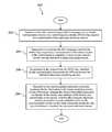
- a method 200is described.
- RFIDradio frequency identity
- send by the RFID chipa request to a communication transceiver coupled to the motherboard to establish a virtual private network tunnel over an Internet to a cloud computing service.
- the communication transceiverconsumer electronic device information to the cloud computing service via the VPN tunnel, wherein the device information comprises an identity of the device, user settings of the device, and current state of the device, whereby the consumer electronic device information is made available to the mobile communication device via the cloud computing service for use by a technician to maintain the consumer electronic device
- the system 300comprises a disk drive memory device 301 and a paired device 330 .
- the disk drive memory device 301comprises a radio frequency transceiver 302 , a processor 304 , a disk memory media 306 , a disk reader/writer 308 , a radio frequency identity (RFID) chip 310 , and a communication bus 311 .
- the disk memory media 306may be a rotating memory disk.
- the memory diskmay be an optical media or a magnetic media.
- the disk reader/writer 308may be referred to in some contexts as an electromechanical disk reader.
- the radio frequency transceiver 302may be a short range radio transceiver configured for transmitting and receiving over relatively short distances, for example less than 500 feet, less than 100 feet, or less than 10 feet.
- the radio frequency transceiver 302is a WiFi transceiver, a Bluetooth® transceiver, or an industrial, scientific, and medical (ISM) radio band transceiver.
- the RFID chip 310comprises an internal processor 312 , an internal memory 314 , and a near field communication (NFC) transceiver 320 .
- the internal memory 314comprises a local application 316 and a pair identity 318 .
- the radio frequency transceiver 302 , the processor 304 , the disk read/writer 308 , and the RFID chip 310communicate with each other, as needed, via the communication bus 311 .
- the RFID chip 310may receive power from the disk drive memory device 301 in some operation modes, for example from a battery (not shown) or from a power supply (not shown) of the disk drive memory device 301 .
- the RFID chip 310is further configured to operate in a passive power mode where it derives electrical power from an incident radio frequency field.
- the passive power modemay provide a number of advantageous functions.
- the disk drive memory device 301may be read, via the RFID chip 310 , in a maintenance facility or a distribution facility to determine a state of the disk drive memory device 301 or to determine other information about the disk drive memory device 301 .
- the disk drive memory device 301may have the pair identity 318 transmitted to the RFID chip 310 and stored in the pair identity 318 of the internal memory 314 during a passive power mode.
- the radio frequency transceiver 302receives a request from the radio frequency transceiver 332 of the paired device 330 to read or write the disk memory media 306 .
- the processor 304generates a read or write request, sends this request over the communication bus 311 to the disk reader/writer 308 , and the disk reader/writer 308 writes data to or reads data from the disk memory media 306 responsive to the request from the processor 304 .
- the disk reader/writer 308sends the read data to the processor 304 , the processor 304 sends the data to the radio frequency transceiver 302 , and the radio frequency transceiver 302 transmits the data wirelessly to the radio frequency transceiver 332 of the paired device 330 .
- the system 300represents an association between the disk drive memory device 301 and the paired device 330 .
- the disk drive memory device 301is physically separate from or separable from (e.g., separable by disconnecting a communication cable or dongle).
- the disk drive memory device 301is intended to support operations of the paired device 330 and store data, access to which may desirably be restricted to the paired device 330 .
- the disk drive memory device 301may be, for example, an expansion memory device associated with the paired device 330 .
- the paired device 330may be a laptop computer, a desktop computer, a tablet computer, a notebook computer, a headset computer, a wearable computer, or a mobile phone.
- the paired device 330comprises a radio frequency transceiver 332 , a processor 334 , a memory 336 storing an identity of the paired device 330 , and an NFC transceiver 340 .
- the radio frequency transceiver 332may be a short range radio transceiver configured for transmitting and receiving over relatively short distances, for example less than 500 feet, less than 100 feet, or less than 10 feet.
- the radio frequency transceiver 302is a WiFi transceiver, a Bluetooth® transceiver, or an industrial, scientific, and medical (ISM) radio band transceiver.
- the NFC transceiver 320periodically challenges the NFC transceiver 340 of the paired device 330 to return the identity 338 of the paired device 330 stored in the memory 336 .
- the disk drive memory device 301continues to provide access to the disk memory media 306 via the radio frequency transceiver 302 .
- the identity returned to the NFC transceiver 320 of the RFID chip 310does not match the pair identity 318 or if no identity is returned to the NFC transceiver 320 , access to the disk memory media 306 may be suspended.
- the local application 316may communicate via the communication bus 311 with an application executing on the processor 304 , and that application executing on the processor 304 may refuse authorized access to the disk memory media 306 via the radio frequency transceiver 302 . This may be referred to as sending an authorization denial from the RFID chip 310 and/or from the local application 316 to the processor 304 .
- the RFID chip 310sends the identity 338 of the paired device 330 or the pair identity 318 stored in the internal memory 314 to the processor 304 , and the processor 304 compares the identity 318 / 338 with a corresponding identity presented in the memory read/write request from the paired device 330 received via the radio frequency transceiver 302 .
- the processor 304compares the identities and in the event of match allows the access and in the event of mismatch, disallows the access.
- the functionality described above with reference to FIG. 3may be advantageously extended to a solid state (i.e., semiconductor based) mass memory device. In such a solid state memory device, the disk drive memory device 301 may be substituted for by a memory device.
- the memory devicemay comprise a memory media in the place of the disk memory media 306 , a memory reader/writer in the place of the disk reader/writer 308 .
- the memory reader/writermay be referred to solely as a memory reader, for example when the reader function is referred to.
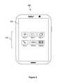
- FIG. 4depicts the user equipment (UE) 400 , which is operable for implementing aspects of the present disclosure, but the present disclosure should not be limited to these implementations.
- the UE 400may take various forms including a wireless handset, a pager, a personal digital assistant (PDA), a gaming device, or a media player.
- the UE 400includes a touchscreen display 402 having a touch-sensitive surface for input by a user.
- a small number of application icons 404are illustrated within the touch screen display 402 . It is understood that in different embodiments, any number of application icons 404 may be presented in the touch screen display 402 .
- a usermay be able to download and install additional applications on the UE 400 , and an icon associated with such downloaded and installed applications may be added to the touch screen display 402 or to an alternative screen.
- the UE 400may have other components such as electro-mechanical switches, speakers, camera lenses, microphones, input and/or output connectors, and other components as are well known in the art.
- the UE 400may present options for the user to select, controls for the user to actuate, and/or cursors or other indicators for the user to direct.
- the UE 400may further accept data entry from the user, including numbers to dial or various parameter values for configuring the operation of the handset.
- the UE 400may further execute one or more software or firmware applications in response to user commands.
- the UE 400may be programmed and/or configured over-the-air, for example from a wireless base station, a wireless access point, or a peer UE 400 .
- the UE 400may execute a web browser application which enables the touch screen display 402 to show a web page.
- the web pagemay be obtained via wireless communications with a base transceiver station, a wireless network access node, a peer UE 400 or any other wireless communication network or system.
- FIG. 5shows a block diagram of the UE 400 . While a variety of known components of handsets are depicted, in an embodiment a subset of the listed components and/or additional components not listed may be included in the UE 400 .
- the UE 400includes a digital signal processor (DSP) 502 and a memory 504 .
- DSPdigital signal processor
- the UE 400may further include an antenna and front end unit 506 , a radio frequency (RF) transceiver 508 , a baseband processing unit 510 , a microphone 512 , an earpiece speaker 514 , a headset port 516 , an input/output interface 518 , a removable memory card 520 , a universal serial bus (USB) port 522 , an infrared port 524 , a vibrator 526 , one or more electro-mechanical switches 528 , a touch screen liquid crystal display (LCD) with a touch screen display 530 , a touch screen/LCD controller 532 , a camera 534 , a camera controller 536 , and a global positioning system (GPS) receiver 538 .
- RFradio frequency
- the UE 400may include another kind of display that does not provide a touch sensitive screen. In an embodiment, the UE 400 may include both the touch screen display 530 and additional display component that does not provide a touch sensitive screen. In an embodiment, the DSP 502 may communicate directly with the memory 504 without passing through the input/output interface 518 . Additionally, in an embodiment, the UE 400 may comprise other peripheral devices that provide other functionality.
- the DSP 502or some other form of controller or central processing unit operates to control the various components of the UE 400 in accordance with embedded software or firmware stored in memory 504 or stored in memory contained within the DSP 502 itself.
- the DSP 502may execute other applications stored in the memory 504 or made available via information carrier media such as portable data storage media like the removable memory card 520 or via wired or wireless network communications.
- the application softwaremay comprise a compiled set of machine-readable instructions that configure the DSP 502 to provide the desired functionality, or the application software may be high-level software instructions to be processed by an interpreter or compiler to indirectly configure the DSP 502 .
- the DSP 502may communicate with a wireless network via the analog baseband processing unit 510 .
- the communicationmay provide Internet connectivity, enabling a user to gain access to content on the Internet and to send and receive e-mail or text messages.
- the input/output interface 518interconnects the DSP 502 and various memories and interfaces.
- the memory 504 and the removable memory card 520may provide software and data to configure the operation of the DSP 502 .
- the interfacesmay be the USB port 522 and the infrared port 524 .
- the USB port 522may enable the UE 400 to function as a peripheral device to exchange information with a personal computer or other computer system.
- the infrared port 524 and other optional portsmay enable the UE 400 to communicate wirelessly with other nearby handsets and/or wireless base stations.
- the UE 400may comprise a near field communication (NFC) transceiver.
- the NFC transceivermay be used to complete payment transactions with point-of-sale terminals or other communications exchanges.
- the UE 400may comprise a radio frequency identify (RFID) reader and/or writer device.
- RFIDradio frequency identify
- the switches 528may couple to the DSP 502 via the input/output interface 518 to provide one mechanism for the user to provide input to the UE 400 .
- one or more of the switches 528may be coupled to a motherboard of the UE 400 and/or to components of the UE 400 via a different path (e.g., not via the input/output interface 518 ), for example coupled to a power control circuit (power button) of the UE 400 .
- the touch screen display 530is another input mechanism, which further displays text and/or graphics to the user.
- the touch screen LCD controller 532couples the DSP 502 to the touch screen display 530 .
- the GPS receiver 538is coupled to the DSP 502 to decode global positioning system signals, thereby enabling the UE 400 to determine its position.
- FIG. 6Aillustrates a software environment 602 that may be implemented by the DSP 502 .
- the DSP 502executes operating system software 604 that provides a platform from which the rest of the software operates.
- the operating system software 604may provide a variety of drivers for the handset hardware with standardized interfaces that are accessible to application software.
- the operating system software 604may be coupled to and interact with application management services (AMS) 606 that transfer control between applications running on the UE 400 .
- AMSapplication management services
- FIG. 6Aare also shown in FIG. 6A a web browser application 608 , a media player application 610 , and JAVA applets 612 .
- the web browser application 608may be executed by the UE 400 to browse content and/or the Internet, for example when the UE 400 is coupled to a network via a wireless link.
- the web browser application 608may permit a user to enter information into forms and select links to retrieve and view web pages.
- the media player application 610may be executed by the UE 400 to play audio or audiovisual media.
- the JAVA applets 612may be executed by the UE 400 to provide a variety of functionality including games, utilities, and other functionality.
- FIG. 6Billustrates an alternative software environment 620 that may be implemented by the DSP 502 .
- the DSP 502executes operating system kernel (OS kernel) 628 and an execution runtime 630 .
- the DSP 502executes applications 622 that may execute in the execution runtime 630 and may rely upon services provided by the application framework 624 .
- Applications 622 and the application framework 624may rely upon functionality provided via the libraries 626 .
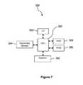
- FIG. 7illustrates a computer system 380 suitable for implementing one or more embodiments disclosed herein.
- the application server 112may be implemented as a computer system.
- the content data store 110may be implemented as or may be accessed via a computer system.
- the NFC scanner 104may be implemented as a computer system.
- the computer system 380includes a processor 382 (which may be referred to as a central processor unit or CPU) that is in communication with memory devices including secondary storage 384 , read only memory (ROM) 386 , random access memory (RAM) 388 , input/output (I/O) devices 390 , and network connectivity devices 392 .
- the processor 382may be implemented as one or more CPU chips.
- a design that is still subject to frequent changemay be preferred to be implemented in software, because re-spinning a hardware implementation is more expensive than re-spinning a software design.
- a design that is stable that will be produced in large volumemay be preferred to be implemented in hardware, for example in an application specific integrated circuit (ASIC), because for large production runs the hardware implementation may be less expensive than the software implementation.
- ASICapplication specific integrated circuit
- a designmay be developed and tested in a software form and later transformed, by well-known design rules, to an equivalent hardware implementation in an application specific integrated circuit that hardwires the instructions of the software.
- a machine controlled by a new ASICis a particular machine or apparatus, likewise a computer that has been programmed and/or loaded with executable instructions may be viewed as a particular machine or apparatus.
- the CPU 382may execute a computer program or application.
- the CPU 382may execute software or firmware stored in the ROM 386 or stored in the RAM 388 .
- the CPU 382may copy the application or portions of the application from the secondary storage 384 to the RAM 388 or to memory space within the CPU 382 itself, and the CPU 382 may then execute instructions that the application is comprised of.
- the CPU 382may copy the application or portions of the application from memory accessed via the network connectivity devices 392 or via the I/O devices 390 to the RAM 388 or to memory space within the CPU 382 , and the CPU 382 may then execute instructions that the application is comprised of.
- an applicationmay load instructions into the CPU 382 , for example load some of the instructions of the application into a cache of the CPU 382 .
- an application that is executedmay be said to configure the CPU 382 to do something, e.g., to configure the CPU 382 to perform the function or functions promoted by the subject application.
- the CPU 382becomes a specific purpose computer or a specific purpose machine.
- the secondary storage 384is typically comprised of one or more disk drives or tape drives and is used for non-volatile storage of data and as an over-flow data storage device if RAM 388 is not large enough to hold all working data. Secondary storage 384 may be used to store programs which are loaded into RAM 388 when such programs are selected for execution.
- the ROM 386is used to store instructions and perhaps data which are read during program execution. ROM 386 is a non-volatile memory device which typically has a small memory capacity relative to the larger memory capacity of secondary storage 384 .
- the RAM 388is used to store volatile data and perhaps to store instructions. Access to both ROM 386 and RAM 388 is typically faster than to secondary storage 384 .
- the secondary storage 384 , the RAM 388 , and/or the ROM 386may be referred to in some contexts as computer readable storage media and/or non-transitory computer readable media.
- I/O devices 390may include printers, video monitors, liquid crystal displays (LCDs), touch screen displays, keyboards, keypads, switches, dials, mice, track balls, voice recognizers, card readers, paper tape readers, or other well-known input devices.
- LCDsliquid crystal displays
- touch screen displayskeyboards, keypads, switches, dials, mice, track balls, voice recognizers, card readers, paper tape readers, or other well-known input devices.
- the network connectivity devices 392may take the form of modems, modem banks, Ethernet cards, universal serial bus (USB) interface cards, serial interfaces, token ring cards, fiber distributed data interface (FDDI) cards, wireless local area network (WLAN) cards, radio transceiver cards that promote radio communications using protocols such as code division multiple access (CDMA), global system for mobile communications (GSM), long-term evolution (LTE), worldwide interoperability for microwave access (WiMAX), near field communications (NFC), radio frequency identity (RFID), and/or other air interface protocol radio transceiver cards, and other well-known network devices. These network connectivity devices 392 may enable the processor 382 to communicate with the Internet or one or more intranets.
- CDMAcode division multiple access
- GSMglobal system for mobile communications
- LTElong-term evolution
- WiMAXworldwide interoperability for microwave access
- NFCnear field communications
- RFIDradio frequency identity
- RFIDradio frequency identity
- the processor 382might receive information from the network, or might output information to the network in the course of performing the above-described method steps. Such information, which is often represented as a sequence of instructions to be executed using processor 382 , may be received from and outputted to the network, for example, in the form of a computer data signal embodied in a carrier wave.
- Such informationmay be received from and outputted to the network, for example, in the form of a computer data baseband signal or signal embodied in a carrier wave.
- the baseband signal or signal embedded in the carrier wavemay be generated according to several methods well-known to one skilled in the art.
- the baseband signal and/or signal embedded in the carrier wavemay be referred to in some contexts as a transitory signal.
- the processor 382executes instructions, codes, computer programs, scripts which it accesses from hard disk, floppy disk, optical disk (these various disk based systems may all be considered secondary storage 384 ), flash drive, ROM 386 , RAM 388 , or the network connectivity devices 392 . While only one processor 382 is shown, multiple processors may be present. Thus, while instructions may be discussed as executed by a processor, the instructions may be executed simultaneously, serially, or otherwise executed by one or multiple processors.
- Instructions, codes, computer programs, scripts, and/or data that may be accessed from the secondary storage 384for example, hard drives, floppy disks, optical disks, and/or other device, the ROM 386 , and/or the RAM 388 may be referred to in some contexts as non-transitory instructions and/or non-transitory information.
- the computer system 380may comprise two or more computers in communication with each other that collaborate to perform a task.
- an applicationmay be partitioned in such a way as to permit concurrent and/or parallel processing of the instructions of the application.
- the data processed by the applicationmay be partitioned in such a way as to permit concurrent and/or parallel processing of different portions of a data set by the two or more computers.
- virtualization softwaremay be employed by the computer system 380 to provide the functionality of a number of servers that is not directly bound to the number of computers in the computer system 380 .
- virtualization softwaremay provide twenty virtual servers on four physical computers.
- Cloud computingmay comprise providing computing services via a network connection using dynamically scalable computing resources.
- Cloud computingmay be supported, at least in part, by virtualization software.
- a cloud computing environmentmay be established by an enterprise and/or may be hired on an as-needed basis from a third party provider.
- Some cloud computing environmentsmay comprise cloud computing resources owned and operated by the enterprise as well as cloud computing resources hired and/or leased from a third party provider.
- the computer program productmay comprise one or more computer readable storage medium having computer usable program code embodied therein to implement the functionality disclosed above.
- the computer program productmay comprise data structures, executable instructions, and other computer usable program code.
- the computer program productmay be embodied in removable computer storage media and/or non-removable computer storage media.
- the removable computer readable storage mediummay comprise, without limitation, a paper tape, a magnetic tape, magnetic disk, an optical disk, a solid state memory chip, for example analog magnetic tape, compact disk read only memory (CD-ROM) disks, floppy disks, jump drives, digital cards, multimedia cards, and others.
- the computer program productmay be suitable for loading, by the computer system 380 , at least portions of the contents of the computer program product to the secondary storage 384 , to the ROM 386 , to the RAM 388 , and/or to other non-volatile memory and volatile memory of the computer system 380 .
- the processor 382may process the executable instructions and/or data structures in part by directly accessing the computer program product, for example by reading from a CD-ROM disk inserted into a disk drive peripheral of the computer system 380 .
- the processor 382may process the executable instructions and/or data structures by remotely accessing the computer program product, for example by downloading the executable instructions and/or data structures from a remote server through the network connectivity devices 392 .
- the computer program productmay comprise instructions that promote the loading and/or copying of data, data structures, files, and/or executable instructions to the secondary storage 384 , to the ROM 386 , to the RAM 388 , and/or to other non-volatile memory and volatile memory of the computer system 380 .
- the secondary storage 384 , the ROM 386 , and the RAM 388may be referred to as a non-transitory computer readable medium or a computer readable storage media.
- a dynamic RAM embodiment of the RAM 388likewise, may be referred to as a non-transitory computer readable medium in that while the dynamic RAM receives electrical power and is operated in accordance with its design, for example during a period of time during which the computer system 380 is turned on and operational, the dynamic RAM stores information that is written to it.
- the processor 382may comprise an internal RAM, an internal ROM, a cache memory, and/or other internal non-transitory storage blocks, sections, or components that may be referred to in some contexts as non-transitory computer readable media or computer readable storage media.
Landscapes
- Engineering & Computer Science (AREA)
- Computer Networks & Wireless Communication (AREA)
- Signal Processing (AREA)
- Computer Security & Cryptography (AREA)
- Computer Hardware Design (AREA)
- Computing Systems (AREA)
- General Engineering & Computer Science (AREA)
- Mobile Radio Communication Systems (AREA)
Abstract
Description
Claims (19)
Priority Applications (1)
| Application Number | Priority Date | Filing Date | Title |
|---|---|---|---|
| US14/696,835US9591434B1 (en) | 2015-04-27 | 2015-04-27 | Virtual private network (VPN) tunneling in a user equipment (UE) brokered by a radio frequency identity (RFID) chip communicatively coupled to the user equipment |
Applications Claiming Priority (1)
| Application Number | Priority Date | Filing Date | Title |
|---|---|---|---|
| US14/696,835US9591434B1 (en) | 2015-04-27 | 2015-04-27 | Virtual private network (VPN) tunneling in a user equipment (UE) brokered by a radio frequency identity (RFID) chip communicatively coupled to the user equipment |
Publications (1)
| Publication Number | Publication Date |
|---|---|
| US9591434B1true US9591434B1 (en) | 2017-03-07 |
Family
ID=58162305
Family Applications (1)
| Application Number | Title | Priority Date | Filing Date |
|---|---|---|---|
| US14/696,835Active2035-08-10US9591434B1 (en) | 2015-04-27 | 2015-04-27 | Virtual private network (VPN) tunneling in a user equipment (UE) brokered by a radio frequency identity (RFID) chip communicatively coupled to the user equipment |
Country Status (1)
| Country | Link |
|---|---|
| US (1) | US9591434B1 (en) |
Cited By (8)
| Publication number | Priority date | Publication date | Assignee | Title |
|---|---|---|---|---|
| US9712999B1 (en) | 2013-04-04 | 2017-07-18 | Sprint Communications Company L.P. | Digest of biographical information for an electronic device with static and dynamic portions |
| US9763033B1 (en) | 2013-04-30 | 2017-09-12 | Sprint Communications Company L.P. | Prevention of inductive coupling between components of a mobile communication device |
| US20170345043A1 (en)* | 2016-05-31 | 2017-11-30 | Ncr Corporation | Contactless identification and locating |
| US20180095435A1 (en)* | 2016-09-30 | 2018-04-05 | Siemens Industry Inc. | Systems and methods for rapid industrial network troubleshooting for automation systems |
| US20180234395A1 (en)* | 2017-02-16 | 2018-08-16 | Telia Company Ab | Methods and Apparatuses for Providing Security in a Roaming Environment |
| US20220174046A1 (en)* | 2016-02-01 | 2022-06-02 | Airwatch Llc | Configuring network security based on device management characteristics |
| US20230040723A1 (en)* | 2021-08-09 | 2023-02-09 | International Business Machines Corporation | Packet authentication in a vxlan system |
| US20240388900A1 (en)* | 2023-05-17 | 2024-11-21 | Verizon Patent And Licensing Inc. | Systems and methods for ephemeral token-based device identifier detection |
Citations (65)
| Publication number | Priority date | Publication date | Assignee | Title |
|---|---|---|---|---|
| US6177860B1 (en) | 1997-11-17 | 2001-01-23 | International Business Machines Corporation | Method and economical direct connected apparatus for deploying and tracking computers |
| US6726099B2 (en)* | 2002-09-05 | 2004-04-27 | Honeywell International Inc. | RFID tag having multiple transceivers |
| US6842106B2 (en)* | 2002-10-04 | 2005-01-11 | Battelle Memorial Institute | Challenged-based tag authentication model |
| US20050045719A1 (en) | 2003-08-06 | 2005-03-03 | Samsung Electronics Co., Ltd. | Apparatus and method for managing address book in portable wireless terminal |
| US20050123596A1 (en) | 2003-09-23 | 2005-06-09 | Kohane Daniel S. | pH-triggered microparticles |
| US20050125396A1 (en) | 2003-12-05 | 2005-06-09 | Li-Sen Liu | Electronic apparatus and file search method thereof |
| US20060258289A1 (en) | 2005-05-12 | 2006-11-16 | Robin Dua | Wireless media system and player and method of operation |
| US20070035381A1 (en) | 2005-08-15 | 2007-02-15 | Davis Michael L | Photon authenticated rfid transponder |
| US20070069852A1 (en) | 2005-09-23 | 2007-03-29 | Hee-Sook Mo | Method for securing information between RFID reader and tag, and RFID reader and tag using the same |
| US20070075140A1 (en) | 2005-10-04 | 2007-04-05 | Gregory Guez | Means to deactivate a contactless device |
| US7245213B1 (en) | 2004-05-24 | 2007-07-17 | Impinj, Inc. | RFID readers and RFID tags exchanging encrypted password |
| US20080051142A1 (en) | 2004-03-31 | 2008-02-28 | Telenor Asa | Subscriber Identity Module |
| US7339476B2 (en)* | 2004-11-10 | 2008-03-04 | Rockwell Automation Technologies, Inc. | Systems and methods that integrate radio frequency identification (RFID) technology with industrial controllers |
| US7366806B2 (en)* | 2004-07-27 | 2008-04-29 | Intel Corporation | Method and apparatus for RFID tag wherein memory of RFID tag is partitioned into two sections for reading using wireless interface and writing using bus |
| US20080198098A1 (en) | 2006-10-21 | 2008-08-21 | Metrologic Instruments, Inc. | Electronic sign |
| US20080232259A1 (en) | 2007-03-21 | 2008-09-25 | Cisco Technology, Inc. | Fault Reporting Tag for Mesh Access Points |
| US7450010B1 (en) | 2006-04-17 | 2008-11-11 | Tc License Ltd. | RFID mutual authentication verification session |
| US20080303637A1 (en) | 2003-09-03 | 2008-12-11 | Metrologic Instruments, Inc. | Updateable electronic-ink based display label device |
| US20090164800A1 (en) | 2007-12-21 | 2009-06-25 | Petri Mikael Johansson | Secure End-of-Life Handling of Electronic Devices |
| US20090227290A1 (en) | 2001-12-05 | 2009-09-10 | Herman Chien | Methods and apparatus for anonymous user identification and content personalization in wireless communication |
| US20100075669A1 (en) | 2008-08-15 | 2010-03-25 | Sparks Robert J | Systems, methods, and computer readable media for providing dynaminc steering of roaming in a telecommunications network |
| US7834743B2 (en) | 2004-06-10 | 2010-11-16 | Panasonic Corporation | RFID tag and RFID tag communication distance modification method |
| US20110063093A1 (en) | 2009-07-10 | 2011-03-17 | Certicom Corp. | System and method for performing serialization of devices |
| US7924156B2 (en)* | 2005-05-06 | 2011-04-12 | Colby Steven M | Electronically switchable RFID tags |
| US20110254687A1 (en) | 2010-04-15 | 2011-10-20 | Nokia Corporation | Method and apparatus for activating a device |
| US8138922B2 (en) | 2004-04-30 | 2012-03-20 | Binforma Group Limited Liability Company | Deactivating a data tag for user privacy or tamper-evident packaging |
| US20120077468A1 (en)* | 2010-09-24 | 2012-03-29 | At&T Intellectual Property I, L.P. | Providing integrated service-entity premium communication services |
| US20120079100A1 (en) | 2010-05-28 | 2012-03-29 | Motorola Mobility, Inc. | Electronic device diagnostic systems and methods |
| US8174384B2 (en) | 2008-09-05 | 2012-05-08 | Psion Teklogix Inc. | Method and system for controlling read range of a portable RFID reader |
| US20120149338A1 (en) | 2007-02-14 | 2012-06-14 | Brian Roundtree | System and method for securely managing data stored on mobile devices, such as enterprise mobility data |
| US20120150601A1 (en) | 2006-08-25 | 2012-06-14 | Blaze Mobile, Inc. | Single tap transactions using an nfc enabled mobile device |
| US8217793B2 (en) | 2008-12-12 | 2012-07-10 | Symbol Technologies, Inc. | Rogue RFID detector |
| US20120184367A1 (en) | 2011-01-14 | 2012-07-19 | Igt | Wearable casino gaming display and tracking system |
| US20120196586A1 (en) | 2011-01-31 | 2012-08-02 | Bank Of America Corporation | Transferring content to a mobile device |
| US20120238206A1 (en)* | 2011-03-14 | 2012-09-20 | Research In Motion Limited | Communications device providing near field communication (nfc) secure element disabling features related methods |
| US20120262281A1 (en) | 2011-04-15 | 2012-10-18 | Polycom, Inc. | System and method for in-box electronic device provisioning |
| US8311509B2 (en) | 2005-08-03 | 2012-11-13 | Kamilo Feher | Detection, communication and control in multimode cellular, TDMA, GSM, spread spectrum, CDMA, OFDM WiLAN and WiFi systems |
| US20130105565A1 (en) | 2011-10-29 | 2013-05-02 | Richard Alan Kamprath | Nutritional Information System |
| US8471708B1 (en) | 2010-02-22 | 2013-06-25 | Impinj, Inc. | RFID tags and readers employing QT command to switch tag profiles |
| US20130175984A1 (en) | 2012-01-05 | 2013-07-11 | Nitto Denko Corporation | Mobile terminal power receiving module utilizing wireless power transmission and mobile terminal rechargable battery including mobile terminal power receiving module |
| US8487769B2 (en) | 2004-04-30 | 2013-07-16 | Binforma Group Limited Liability Company | Reversibly deactivating a radio frequency identification data tag |
| US8718554B2 (en) | 2006-02-15 | 2014-05-06 | Microsoft Corporation | Means for provisioning and managing mobile device configuration over a near-field communication link |
| US20140141718A1 (en) | 2010-01-05 | 2014-05-22 | Iota, Inc. | Mobile communications resource management system |
| US8752127B2 (en)* | 2011-05-26 | 2014-06-10 | First Data Corporation | Systems and methods for identifying devices by a trusted service manager |
| US8797144B2 (en) | 2011-10-31 | 2014-08-05 | Eastman Kodak Company | Authorizing RFID reader and inhibiting skimming |
| US8811971B2 (en)* | 2007-08-01 | 2014-08-19 | Nxp B.V. | Mobile communication device and method for disabling applications |
| US8816826B2 (en)* | 2005-05-06 | 2014-08-26 | Steven M. Colby | Passive radio frequency data logger |
| US8866594B1 (en) | 2011-02-17 | 2014-10-21 | Impinj, Inc. | RFID tag and reader authentication by trusted authority |
| US20150019444A1 (en)* | 2013-07-11 | 2015-01-15 | Visa International Service Association | Augmented Smart Tag Security Apparatuses, Methods and Systems |
| US9087318B1 (en)* | 2013-11-08 | 2015-07-21 | Sprint Communications Company L.P. | Visually readable electronic label |
| US9111280B2 (en)* | 2010-04-16 | 2015-08-18 | Visa International Service Association | General purpose messaging |
| US9161325B1 (en)* | 2013-11-20 | 2015-10-13 | Sprint Communications Company L.P. | Subscriber identity module virtualization |
| US9171243B1 (en)* | 2013-04-04 | 2015-10-27 | Sprint Communications Company L.P. | System for managing a digest of biographical information stored in a radio frequency identity chip coupled to a mobile communication device |
| US9191522B1 (en)* | 2013-11-08 | 2015-11-17 | Sprint Communications Company L.P. | Billing varied service based on tier |
| US9226145B1 (en)* | 2014-03-28 | 2015-12-29 | Sprint Communications Company L.P. | Verification of mobile device integrity during activation |
| US9230085B1 (en)* | 2014-07-29 | 2016-01-05 | Sprint Communications Company L.P. | Network based temporary trust extension to a remote or mobile device enabled via specialized cloud services |
| US9253589B2 (en) | 2012-03-12 | 2016-02-02 | Blackberry Limited | Wireless local area network hotspot registration using near field communications |
| US9324016B1 (en) | 2013-04-04 | 2016-04-26 | Sprint Communications Company L.P. | Digest of biographical information for an electronic device with static and dynamic portions |
| US9384498B1 (en)* | 2012-08-25 | 2016-07-05 | Sprint Communications Company L.P. | Framework for real-time brokering of digital content delivery |
| US9398428B2 (en)* | 2014-08-26 | 2016-07-19 | Verizon Patent And Licensing Inc. | Enterprise messaging client and messaging archive |
| US9396424B1 (en)* | 2014-11-04 | 2016-07-19 | Sprint Communications Company L.P. | Radio frequency induced power reception management for a radio frequency identity (RFID) chip embedded in a mobile communication device |
| US9426604B1 (en) | 2013-04-30 | 2016-08-23 | Sprint Communications Company L.P. | Prevention of inductive coupling between components of a mobile communication device |
| US9432364B2 (en)* | 2008-12-12 | 2016-08-30 | Sk Telecom Co., Ltd. | System and method for providing a service to end terminal that uses authentication information of another mobile communication terminal, service server, mobile communication terminal, end terminal, and storage medium |
| US9454723B1 (en) | 2013-04-04 | 2016-09-27 | Sprint Communications Company L.P. | Radio frequency identity (RFID) chip electrically and communicatively coupled to motherboard of mobile communication device |
| US9460573B1 (en) | 2014-02-27 | 2016-10-04 | Sprint Communications Company, L.P. | Autonomous authentication of a reader by a radio frequency identity (RFID) device |
- 2015
- 2015-04-27USUS14/696,835patent/US9591434B1/enactiveActive
Patent Citations (68)
| Publication number | Priority date | Publication date | Assignee | Title |
|---|---|---|---|---|
| US6177860B1 (en) | 1997-11-17 | 2001-01-23 | International Business Machines Corporation | Method and economical direct connected apparatus for deploying and tracking computers |
| US20090227290A1 (en) | 2001-12-05 | 2009-09-10 | Herman Chien | Methods and apparatus for anonymous user identification and content personalization in wireless communication |
| US6726099B2 (en)* | 2002-09-05 | 2004-04-27 | Honeywell International Inc. | RFID tag having multiple transceivers |
| US6842106B2 (en)* | 2002-10-04 | 2005-01-11 | Battelle Memorial Institute | Challenged-based tag authentication model |
| US20050045719A1 (en) | 2003-08-06 | 2005-03-03 | Samsung Electronics Co., Ltd. | Apparatus and method for managing address book in portable wireless terminal |
| US20080303637A1 (en) | 2003-09-03 | 2008-12-11 | Metrologic Instruments, Inc. | Updateable electronic-ink based display label device |
| US20050123596A1 (en) | 2003-09-23 | 2005-06-09 | Kohane Daniel S. | pH-triggered microparticles |
| US20050125396A1 (en) | 2003-12-05 | 2005-06-09 | Li-Sen Liu | Electronic apparatus and file search method thereof |
| US20080051142A1 (en) | 2004-03-31 | 2008-02-28 | Telenor Asa | Subscriber Identity Module |
| US8487769B2 (en) | 2004-04-30 | 2013-07-16 | Binforma Group Limited Liability Company | Reversibly deactivating a radio frequency identification data tag |
| US8138922B2 (en) | 2004-04-30 | 2012-03-20 | Binforma Group Limited Liability Company | Deactivating a data tag for user privacy or tamper-evident packaging |
| US7245213B1 (en) | 2004-05-24 | 2007-07-17 | Impinj, Inc. | RFID readers and RFID tags exchanging encrypted password |
| US7834743B2 (en) | 2004-06-10 | 2010-11-16 | Panasonic Corporation | RFID tag and RFID tag communication distance modification method |
| US7366806B2 (en)* | 2004-07-27 | 2008-04-29 | Intel Corporation | Method and apparatus for RFID tag wherein memory of RFID tag is partitioned into two sections for reading using wireless interface and writing using bus |
| US7339476B2 (en)* | 2004-11-10 | 2008-03-04 | Rockwell Automation Technologies, Inc. | Systems and methods that integrate radio frequency identification (RFID) technology with industrial controllers |
| US8816826B2 (en)* | 2005-05-06 | 2014-08-26 | Steven M. Colby | Passive radio frequency data logger |
| US7924156B2 (en)* | 2005-05-06 | 2011-04-12 | Colby Steven M | Electronically switchable RFID tags |
| US8244179B2 (en)* | 2005-05-12 | 2012-08-14 | Robin Dua | Wireless inter-device data processing configured through inter-device transmitted data |
| US20060258289A1 (en) | 2005-05-12 | 2006-11-16 | Robin Dua | Wireless media system and player and method of operation |
| US8311509B2 (en) | 2005-08-03 | 2012-11-13 | Kamilo Feher | Detection, communication and control in multimode cellular, TDMA, GSM, spread spectrum, CDMA, OFDM WiLAN and WiFi systems |
| US20070035381A1 (en) | 2005-08-15 | 2007-02-15 | Davis Michael L | Photon authenticated rfid transponder |
| US20070069852A1 (en) | 2005-09-23 | 2007-03-29 | Hee-Sook Mo | Method for securing information between RFID reader and tag, and RFID reader and tag using the same |
| US20070075140A1 (en) | 2005-10-04 | 2007-04-05 | Gregory Guez | Means to deactivate a contactless device |
| US8718554B2 (en) | 2006-02-15 | 2014-05-06 | Microsoft Corporation | Means for provisioning and managing mobile device configuration over a near-field communication link |
| US7450010B1 (en) | 2006-04-17 | 2008-11-11 | Tc License Ltd. | RFID mutual authentication verification session |
| US20120150601A1 (en) | 2006-08-25 | 2012-06-14 | Blaze Mobile, Inc. | Single tap transactions using an nfc enabled mobile device |
| US20080198098A1 (en) | 2006-10-21 | 2008-08-21 | Metrologic Instruments, Inc. | Electronic sign |
| US20120149338A1 (en) | 2007-02-14 | 2012-06-14 | Brian Roundtree | System and method for securely managing data stored on mobile devices, such as enterprise mobility data |
| US20080232259A1 (en) | 2007-03-21 | 2008-09-25 | Cisco Technology, Inc. | Fault Reporting Tag for Mesh Access Points |
| US8811971B2 (en)* | 2007-08-01 | 2014-08-19 | Nxp B.V. | Mobile communication device and method for disabling applications |
| US20090164800A1 (en) | 2007-12-21 | 2009-06-25 | Petri Mikael Johansson | Secure End-of-Life Handling of Electronic Devices |
| US20100075669A1 (en) | 2008-08-15 | 2010-03-25 | Sparks Robert J | Systems, methods, and computer readable media for providing dynaminc steering of roaming in a telecommunications network |
| US8174384B2 (en) | 2008-09-05 | 2012-05-08 | Psion Teklogix Inc. | Method and system for controlling read range of a portable RFID reader |
| US9432364B2 (en)* | 2008-12-12 | 2016-08-30 | Sk Telecom Co., Ltd. | System and method for providing a service to end terminal that uses authentication information of another mobile communication terminal, service server, mobile communication terminal, end terminal, and storage medium |
| US8217793B2 (en) | 2008-12-12 | 2012-07-10 | Symbol Technologies, Inc. | Rogue RFID detector |
| US20110063093A1 (en) | 2009-07-10 | 2011-03-17 | Certicom Corp. | System and method for performing serialization of devices |
| US20140141718A1 (en) | 2010-01-05 | 2014-05-22 | Iota, Inc. | Mobile communications resource management system |
| US8471708B1 (en) | 2010-02-22 | 2013-06-25 | Impinj, Inc. | RFID tags and readers employing QT command to switch tag profiles |
| US20110254687A1 (en) | 2010-04-15 | 2011-10-20 | Nokia Corporation | Method and apparatus for activating a device |
| US9111280B2 (en)* | 2010-04-16 | 2015-08-18 | Visa International Service Association | General purpose messaging |
| US20120079100A1 (en) | 2010-05-28 | 2012-03-29 | Motorola Mobility, Inc. | Electronic device diagnostic systems and methods |
| US20120077468A1 (en)* | 2010-09-24 | 2012-03-29 | At&T Intellectual Property I, L.P. | Providing integrated service-entity premium communication services |
| US20120184367A1 (en) | 2011-01-14 | 2012-07-19 | Igt | Wearable casino gaming display and tracking system |
| US20120196586A1 (en) | 2011-01-31 | 2012-08-02 | Bank Of America Corporation | Transferring content to a mobile device |
| US8866594B1 (en) | 2011-02-17 | 2014-10-21 | Impinj, Inc. | RFID tag and reader authentication by trusted authority |
| US20120238206A1 (en)* | 2011-03-14 | 2012-09-20 | Research In Motion Limited | Communications device providing near field communication (nfc) secure element disabling features related methods |
| US20120262281A1 (en) | 2011-04-15 | 2012-10-18 | Polycom, Inc. | System and method for in-box electronic device provisioning |
| US8752127B2 (en)* | 2011-05-26 | 2014-06-10 | First Data Corporation | Systems and methods for identifying devices by a trusted service manager |
| US9331996B2 (en)* | 2011-05-26 | 2016-05-03 | First Data Corporation | Systems and methods for identifying devices by a trusted service manager |
| US20130105565A1 (en) | 2011-10-29 | 2013-05-02 | Richard Alan Kamprath | Nutritional Information System |
| US8797144B2 (en) | 2011-10-31 | 2014-08-05 | Eastman Kodak Company | Authorizing RFID reader and inhibiting skimming |
| US20130175984A1 (en) | 2012-01-05 | 2013-07-11 | Nitto Denko Corporation | Mobile terminal power receiving module utilizing wireless power transmission and mobile terminal rechargable battery including mobile terminal power receiving module |
| US9253589B2 (en) | 2012-03-12 | 2016-02-02 | Blackberry Limited | Wireless local area network hotspot registration using near field communications |
| US9384498B1 (en)* | 2012-08-25 | 2016-07-05 | Sprint Communications Company L.P. | Framework for real-time brokering of digital content delivery |
| US9171243B1 (en)* | 2013-04-04 | 2015-10-27 | Sprint Communications Company L.P. | System for managing a digest of biographical information stored in a radio frequency identity chip coupled to a mobile communication device |
| US9324016B1 (en) | 2013-04-04 | 2016-04-26 | Sprint Communications Company L.P. | Digest of biographical information for an electronic device with static and dynamic portions |
| US9454723B1 (en) | 2013-04-04 | 2016-09-27 | Sprint Communications Company L.P. | Radio frequency identity (RFID) chip electrically and communicatively coupled to motherboard of mobile communication device |
| US9426604B1 (en) | 2013-04-30 | 2016-08-23 | Sprint Communications Company L.P. | Prevention of inductive coupling between components of a mobile communication device |
| US20150019444A1 (en)* | 2013-07-11 | 2015-01-15 | Visa International Service Association | Augmented Smart Tag Security Apparatuses, Methods and Systems |
| US9286594B1 (en) | 2013-11-08 | 2016-03-15 | Sprint Communications Company L.P. | Visually readable electronic label |
| US9191522B1 (en)* | 2013-11-08 | 2015-11-17 | Sprint Communications Company L.P. | Billing varied service based on tier |
| US9087318B1 (en)* | 2013-11-08 | 2015-07-21 | Sprint Communications Company L.P. | Visually readable electronic label |
| US9161325B1 (en)* | 2013-11-20 | 2015-10-13 | Sprint Communications Company L.P. | Subscriber identity module virtualization |
| US9460573B1 (en) | 2014-02-27 | 2016-10-04 | Sprint Communications Company, L.P. | Autonomous authentication of a reader by a radio frequency identity (RFID) device |
| US9226145B1 (en)* | 2014-03-28 | 2015-12-29 | Sprint Communications Company L.P. | Verification of mobile device integrity during activation |
| US9230085B1 (en)* | 2014-07-29 | 2016-01-05 | Sprint Communications Company L.P. | Network based temporary trust extension to a remote or mobile device enabled via specialized cloud services |
| US9398428B2 (en)* | 2014-08-26 | 2016-07-19 | Verizon Patent And Licensing Inc. | Enterprise messaging client and messaging archive |
| US9396424B1 (en)* | 2014-11-04 | 2016-07-19 | Sprint Communications Company L.P. | Radio frequency induced power reception management for a radio frequency identity (RFID) chip embedded in a mobile communication device |
Non-Patent Citations (31)
| Title |
|---|
| Cordes, Kevin R., et al., "Autonomous Authentication of a Reader by a Radio Frequency Identity (RFID) Device," filed Feb. 27, 2014, U.S. Appl. No. 14/192,316. |
| Cordes, Kevin R., et al., "Digest of Biographical Information for an Electronic Device with Static and Dynamic Portions," filed Apr. 4, 2013, U.S. Appl. No. 13/857,141. |
| Cordes, Kevin R., et al., "Digest of Biographical Information for an Electronic Device with Static and Dynamic Portions," filed Mar. 14, 2016, U.S. Appl. No. 15/069,921. |
| Cordes, Kevin R., et al., "Prevention of Inductive Coupling Between Components of a Mobile Communication Device ," filed Apr. 30, 2013, U.S. Appl. No. 13/873,813. |
| Cordes, Kevin R., et al., "Prevention of Inductive Coupling Between Components of a Mobile Communication Device ," filed Jul. 8, 2016, U.S. Appl. No. 15/206,002. |
| Cordes, Kevin R., et al., "Radio Frequency Identity (RFID) Chip Electrically and Communicatively Coupled to Motherboard of Mobile Communication Device," filed Apr. 4, 2013, U.S. Appl. No. 13/857,139. |
| Cordes, Kevin R., et al., "System for Managing a Digest of Biographical Information Stored in a Radio Frequency Identity Chip Coupled to a Mobile Communication Device," filed Apr. 4, 2013, U.S. Appl. No. 13/857,138. |
| Cordes, Kevin R., et al., "Visually Readable Electronic Label," filed Jun. 8, 2015, U.S. Appl. No. 14/732,846. |
| Cordes, Kevin R., et al., "Visually Readable Electronic Label," filed Nov. 8, 2013, U.S. Appl. No. 14/076,164. |
| FAIPP Pre-Interview Communication dated Aug. 5, 2015, U.S. Appl. No. 13/857,141, filed Apr. 4, 2013. |
| FAIPP Pre-Interview Communication dated Dec. 30, 2015, U.S. Appl. No. 14/532,954, filed Nov. 4, 2014. |
| FAIPP Pre-Interview Communication dated Feb. 25, 2016, U.S. Appl. No. 14/192,316, filed Feb. 27, 2014. |
| FAIPP Pre-Interview Communication dated Jun. 2, 2015, U.S. Appl. No. 13/857,139 filed Apr. 4, 2013. |
| FAIPP Pre-Interview Communication dated Mar. 2, 2015, U.S. Appl. No. 13/857,138, filed Apr. 4, 2013. |
| FAIPP Pre-Interview Communication dated Oct. 5, 2016, U.S. Appl. No. 15/069,921, filed Mar. 14, 2016. |
| First Action Interview Office Action dated Apr. 20, 2015, U.S. Appl. No. 13/857,138, filed Apr. 4, 2013. |
| Loman, Clint H., et al., "Radio Frequency Induced Power Reception Management for a Radio Frequency Identity (RFID) Chip Embedded in a Mobile Communication Device," filed Nov. 4, 2014, U.S. Appl. No. 14/532,954. |
| Notice of Allowance dated Apr. 22, 2016, U.S. Appl. No. 13/873,813, filed Apr. 30, 2013. |
| Notice of Allowance dated Dec. 17, 2015, U.S. Appl. No. 13/857,141, filed Apr. 4, 2013. |
| Notice of Allowance dated Jun. 1, 2016, U.S. Appl. No. 14/192,316, filed Feb. 27, 2014. |
| Notice of Allowance dated Jun. 11, 2015, U.S. Appl. No. 13/857,138, filed Apr. 4, 2013. |
| Notice of Allowance dated Mar. 24, 2016, U.S. Appl. No. 14/532,954, filed Nov. 4, 2014. |
| Notice of Allowance dated Mar. 26, 2016, U.S. Appl. No. 13/857,139 filed Apr. 4, 2013. |
| Notice of Allowance dated Mar. 6, 2015, U.S. Appl. No. 14/076,164, filed Nov. 8, 2013. |
| Notice of Allowance dated Oct. 29, 2015, U.S. Appl. No. 14/732,846, filed Jun. 8, 2015. |
| Office Action dated Jul. 9, 2015, U.S. Appl. No. 14/732,846, filed Jun. 8, 2015. |
| Office Action dated Nov. 19, 2015, U.S. Appl. No. 13/857,139, filed Apr. 4, 2013. |
| Office Action dated Nov. 2, 2015, U.S. Appl. No. 13/873,813, filed Apr. 30, 2013. |
| Office Action dated Nov. 4, 2014, U.S. Appl. No. 14/076,164, filed Nov. 8, 2013. |
| Restriction Requirement dated Jan. 5, 2015, U.S. Appl. No. 13/857,139, filed Apr. 4, 2013. |
| Restriction Requirement dated Jul. 31, 2015, U.S. Appl. No. 13/873,813, filed Apr. 30, 2013. |
Cited By (11)
| Publication number | Priority date | Publication date | Assignee | Title |
|---|---|---|---|---|
| US9712999B1 (en) | 2013-04-04 | 2017-07-18 | Sprint Communications Company L.P. | Digest of biographical information for an electronic device with static and dynamic portions |
| US9763033B1 (en) | 2013-04-30 | 2017-09-12 | Sprint Communications Company L.P. | Prevention of inductive coupling between components of a mobile communication device |
| US20220174046A1 (en)* | 2016-02-01 | 2022-06-02 | Airwatch Llc | Configuring network security based on device management characteristics |
| US12126596B2 (en)* | 2016-02-01 | 2024-10-22 | Omnissa, Llc | Configuring network security based on device management characteristics |
| US20170345043A1 (en)* | 2016-05-31 | 2017-11-30 | Ncr Corporation | Contactless identification and locating |
| US20180095435A1 (en)* | 2016-09-30 | 2018-04-05 | Siemens Industry Inc. | Systems and methods for rapid industrial network troubleshooting for automation systems |
| US20180234395A1 (en)* | 2017-02-16 | 2018-08-16 | Telia Company Ab | Methods and Apparatuses for Providing Security in a Roaming Environment |
| US10812454B2 (en)* | 2017-02-16 | 2020-10-20 | Telia Company Ab | Methods and apparatuses for providing security in a roaming environment |
| US20230040723A1 (en)* | 2021-08-09 | 2023-02-09 | International Business Machines Corporation | Packet authentication in a vxlan system |
| US11652825B2 (en)* | 2021-08-09 | 2023-05-16 | International Business Machines Corporation | Packet authentication in a VXLAN system |
| US20240388900A1 (en)* | 2023-05-17 | 2024-11-21 | Verizon Patent And Licensing Inc. | Systems and methods for ephemeral token-based device identifier detection |
Similar Documents
| Publication | Publication Date | Title |
|---|---|---|
| US11064347B1 (en) | Electronic subscriber identity module (eSIM) transfer from inactive device | |
| US9591434B1 (en) | Virtual private network (VPN) tunneling in a user equipment (UE) brokered by a radio frequency identity (RFID) chip communicatively coupled to the user equipment | |
| US10614212B1 (en) | Secure software containers | |
| US9191388B1 (en) | Trusted security zone communication addressing on an electronic device | |
| US9118655B1 (en) | Trusted display and transmission of digital ticket documentation | |
| US11678176B1 (en) | Electronic subscriber identity module (eSIM) transfer via activation code | |
| US9230085B1 (en) | Network based temporary trust extension to a remote or mobile device enabled via specialized cloud services | |
| US9049186B1 (en) | Trusted security zone re-provisioning and re-use capability for refurbished mobile devices | |
| US10311246B1 (en) | System and method for secure USIM wireless network access | |
| US9819679B1 (en) | Hardware assisted provenance proof of named data networking associated to device data, addresses, services, and servers | |
| US11910194B2 (en) | Secondary device authentication proxied from authenticated primary device | |
| US9473945B1 (en) | Infrastructure for secure short message transmission | |
| US11716612B1 (en) | Bootstrap electronic subscriber identity module configuration | |
| US9838379B1 (en) | Security tiering in a mobile communication device application framework | |
| US10868808B1 (en) | Server application access authentication based on SIM | |
| US10757089B1 (en) | Mobile phone client application authentication through media access gateway (MAG) | |
| US10694381B1 (en) | System and method for authentication and sharing of subscriber data | |
| US12063509B2 (en) | Hyperledger authorization into a radio access network (RAN) | |
| US11146944B1 (en) | Mobile phone peer-to-peer electronic subscriber identity module (eSIM) transfer | |
| US11570620B2 (en) | Network profile anti-spoofing on wireless gateways | |
| US10045216B1 (en) | WiFi access point connection protocol adaptation | |
| US10282719B1 (en) | Secure and trusted device-based billing and charging process using privilege for network proxy authentication and audit | |
| US11741175B2 (en) | Performance metrics collection and promulgation from within a mobile application | |
| US10798574B1 (en) | Mobile communication device certification framework | |
| US10251064B1 (en) | Unlock of a mobile communication device in a locked state using a 2-dimensional barcode |
Legal Events
| Date | Code | Title | Description |
|---|---|---|---|
| AS | Assignment | Owner name:SPRINT COMMUNICATIONS COMPANY L.P., KANSAS Free format text:ASSIGNMENT OF ASSIGNORS INTEREST;ASSIGNORS:CORDES, KEVIN R.;LOMAN, CLINT H.;PACZKOWSKI, LYLE W.;AND OTHERS;REEL/FRAME:035508/0792 Effective date:20150427 | |
| STCF | Information on status: patent grant | Free format text:PATENTED CASE | |
| AS | Assignment | Owner name:DEUTSCHE BANK TRUST COMPANY AMERICAS, NEW YORK Free format text:GRANT OF FIRST PRIORITY AND JUNIOR PRIORITY SECURITY INTEREST IN PATENT RIGHTS;ASSIGNOR:SPRINT COMMUNICATIONS COMPANY L.P.;REEL/FRAME:041895/0210 Effective date:20170203 | |
| AS | Assignment | Owner name:SPRINT COMMUNICATIONS COMPANY L.P., KANSAS Free format text:TERMINATION AND RELEASE OF FIRST PRIORITY AND JUNIOR PRIORITY SECURITY INTEREST IN PATENT RIGHTS;ASSIGNOR:DEUTSCHE BANK TRUST COMPANY AMERICAS;REEL/FRAME:052969/0475 Effective date:20200401 Owner name:DEUTSCHE BANK TRUST COMPANY AMERICAS, NEW YORK Free format text:SECURITY AGREEMENT;ASSIGNORS:T-MOBILE USA, INC.;ISBV LLC;T-MOBILE CENTRAL LLC;AND OTHERS;REEL/FRAME:053182/0001 Effective date:20200401 | |
| MAFP | Maintenance fee payment | Free format text:PAYMENT OF MAINTENANCE FEE, 4TH YEAR, LARGE ENTITY (ORIGINAL EVENT CODE: M1551); ENTITY STATUS OF PATENT OWNER: LARGE ENTITY Year of fee payment:4 | |
| AS | Assignment | Owner name:T-MOBILE INNOVATIONS LLC, KANSAS Free format text:ASSIGNMENT OF ASSIGNORS INTEREST;ASSIGNOR:SPRINT COMMUNICATIONS COMPANY L.P.;REEL/FRAME:055604/0001 Effective date:20210303 | |
| AS | Assignment | Owner name:SPRINT SPECTRUM LLC, KANSAS Free format text:RELEASE BY SECURED PARTY;ASSIGNOR:DEUTSCHE BANK TRUST COMPANY AMERICAS;REEL/FRAME:062595/0001 Effective date:20220822 Owner name:SPRINT INTERNATIONAL INCORPORATED, KANSAS Free format text:RELEASE BY SECURED PARTY;ASSIGNOR:DEUTSCHE BANK TRUST COMPANY AMERICAS;REEL/FRAME:062595/0001 Effective date:20220822 Owner name:SPRINT COMMUNICATIONS COMPANY L.P., KANSAS Free format text:RELEASE BY SECURED PARTY;ASSIGNOR:DEUTSCHE BANK TRUST COMPANY AMERICAS;REEL/FRAME:062595/0001 Effective date:20220822 Owner name:SPRINTCOM LLC, KANSAS Free format text:RELEASE BY SECURED PARTY;ASSIGNOR:DEUTSCHE BANK TRUST COMPANY AMERICAS;REEL/FRAME:062595/0001 Effective date:20220822 Owner name:CLEARWIRE IP HOLDINGS LLC, KANSAS Free format text:RELEASE BY SECURED PARTY;ASSIGNOR:DEUTSCHE BANK TRUST COMPANY AMERICAS;REEL/FRAME:062595/0001 Effective date:20220822 Owner name:CLEARWIRE COMMUNICATIONS LLC, KANSAS Free format text:RELEASE BY SECURED PARTY;ASSIGNOR:DEUTSCHE BANK TRUST COMPANY AMERICAS;REEL/FRAME:062595/0001 Effective date:20220822 Owner name:BOOST WORLDWIDE, LLC, KANSAS Free format text:RELEASE BY SECURED PARTY;ASSIGNOR:DEUTSCHE BANK TRUST COMPANY AMERICAS;REEL/FRAME:062595/0001 Effective date:20220822 Owner name:ASSURANCE WIRELESS USA, L.P., KANSAS Free format text:RELEASE BY SECURED PARTY;ASSIGNOR:DEUTSCHE BANK TRUST COMPANY AMERICAS;REEL/FRAME:062595/0001 Effective date:20220822 Owner name:T-MOBILE USA, INC., WASHINGTON Free format text:RELEASE BY SECURED PARTY;ASSIGNOR:DEUTSCHE BANK TRUST COMPANY AMERICAS;REEL/FRAME:062595/0001 Effective date:20220822 Owner name:T-MOBILE CENTRAL LLC, WASHINGTON Free format text:RELEASE BY SECURED PARTY;ASSIGNOR:DEUTSCHE BANK TRUST COMPANY AMERICAS;REEL/FRAME:062595/0001 Effective date:20220822 Owner name:PUSHSPRING, LLC, WASHINGTON Free format text:RELEASE BY SECURED PARTY;ASSIGNOR:DEUTSCHE BANK TRUST COMPANY AMERICAS;REEL/FRAME:062595/0001 Effective date:20220822 Owner name:LAYER3 TV, LLC, WASHINGTON Free format text:RELEASE BY SECURED PARTY;ASSIGNOR:DEUTSCHE BANK TRUST COMPANY AMERICAS;REEL/FRAME:062595/0001 Effective date:20220822 Owner name:IBSV LLC, WASHINGTON Free format text:RELEASE BY SECURED PARTY;ASSIGNOR:DEUTSCHE BANK TRUST COMPANY AMERICAS;REEL/FRAME:062595/0001 Effective date:20220822 | |
| MAFP | Maintenance fee payment | Free format text:PAYMENT OF MAINTENANCE FEE, 8TH YEAR, LARGE ENTITY (ORIGINAL EVENT CODE: M1552); ENTITY STATUS OF PATENT OWNER: LARGE ENTITY Year of fee payment:8 |