US9588516B1 - Unmanned aerial vehicle visual line of sight control - Google Patents
Unmanned aerial vehicle visual line of sight controlDownload PDFInfo
- Publication number
- US9588516B1 US9588516B1US15/094,802US201615094802AUS9588516B1US 9588516 B1US9588516 B1US 9588516B1US 201615094802 AUS201615094802 AUS 201615094802AUS 9588516 B1US9588516 B1US 9588516B1
- Authority
- US
- United States
- Prior art keywords
- uav
- location
- flight
- vlos
- determining
- Prior art date
- Legal status (The legal status is an assumption and is not a legal conclusion. Google has not performed a legal analysis and makes no representation as to the accuracy of the status listed.)
- Active
Links
Images


Classifications
- G—PHYSICS
- G08—SIGNALLING
- G08G—TRAFFIC CONTROL SYSTEMS
- G08G5/00—Traffic control systems for aircraft
- G08G5/50—Navigation or guidance aids
- G08G5/55—Navigation or guidance aids for a single aircraft
- G—PHYSICS
- G05—CONTROLLING; REGULATING
- G05D—SYSTEMS FOR CONTROLLING OR REGULATING NON-ELECTRIC VARIABLES
- G05D1/00—Control of position, course, altitude or attitude of land, water, air or space vehicles, e.g. using automatic pilots
- G05D1/0011—Control of position, course, altitude or attitude of land, water, air or space vehicles, e.g. using automatic pilots associated with a remote control arrangement
- G05D1/0033—Control of position, course, altitude or attitude of land, water, air or space vehicles, e.g. using automatic pilots associated with a remote control arrangement by having the operator tracking the vehicle either by direct line of sight or via one or more cameras located remotely from the vehicle
- B—PERFORMING OPERATIONS; TRANSPORTING
- B64—AIRCRAFT; AVIATION; COSMONAUTICS
- B64C—AEROPLANES; HELICOPTERS
- B64C39/00—Aircraft not otherwise provided for
- B64C39/02—Aircraft not otherwise provided for characterised by special use
- B64C39/024—Aircraft not otherwise provided for characterised by special use of the remote controlled vehicle type, i.e. RPV
- B—PERFORMING OPERATIONS; TRANSPORTING
- B64—AIRCRAFT; AVIATION; COSMONAUTICS
- B64D—EQUIPMENT FOR FITTING IN OR TO AIRCRAFT; FLIGHT SUITS; PARACHUTES; ARRANGEMENT OR MOUNTING OF POWER PLANTS OR PROPULSION TRANSMISSIONS IN AIRCRAFT
- B64D47/00—Equipment not otherwise provided for
- B64D47/08—Arrangements of cameras
- G—PHYSICS
- G05—CONTROLLING; REGULATING
- G05D—SYSTEMS FOR CONTROLLING OR REGULATING NON-ELECTRIC VARIABLES
- G05D1/00—Control of position, course, altitude or attitude of land, water, air or space vehicles, e.g. using automatic pilots
- G05D1/0055—Control of position, course, altitude or attitude of land, water, air or space vehicles, e.g. using automatic pilots with safety arrangements
- G05D1/0061—Control of position, course, altitude or attitude of land, water, air or space vehicles, e.g. using automatic pilots with safety arrangements for transition from automatic pilot to manual pilot and vice versa
- G—PHYSICS
- G05—CONTROLLING; REGULATING
- G05D—SYSTEMS FOR CONTROLLING OR REGULATING NON-ELECTRIC VARIABLES
- G05D1/00—Control of position, course, altitude or attitude of land, water, air or space vehicles, e.g. using automatic pilots
- G05D1/0094—Control of position, course, altitude or attitude of land, water, air or space vehicles, e.g. using automatic pilots involving pointing a payload, e.g. camera, weapon, sensor, towards a fixed or moving target
- G—PHYSICS
- G05—CONTROLLING; REGULATING
- G05D—SYSTEMS FOR CONTROLLING OR REGULATING NON-ELECTRIC VARIABLES
- G05D1/00—Control of position, course, altitude or attitude of land, water, air or space vehicles, e.g. using automatic pilots
- G05D1/02—Control of position or course in two dimensions
- G05D1/021—Control of position or course in two dimensions specially adapted to land vehicles
- G05D1/0268—Control of position or course in two dimensions specially adapted to land vehicles using internal positioning means
- G05D1/0274—Control of position or course in two dimensions specially adapted to land vehicles using internal positioning means using mapping information stored in a memory device
- G—PHYSICS
- G05—CONTROLLING; REGULATING
- G05D—SYSTEMS FOR CONTROLLING OR REGULATING NON-ELECTRIC VARIABLES
- G05D1/00—Control of position, course, altitude or attitude of land, water, air or space vehicles, e.g. using automatic pilots
- G05D1/20—Control system inputs
- G05D1/22—Command input arrangements
- G05D1/221—Remote-control arrangements
- G05D1/222—Remote-control arrangements operated by humans
- G05D1/2235—Remote-control arrangements operated by humans involving the operator tracking the vehicle by direct line of sight
- G—PHYSICS
- G05—CONTROLLING; REGULATING
- G05D—SYSTEMS FOR CONTROLLING OR REGULATING NON-ELECTRIC VARIABLES
- G05D1/00—Control of position, course, altitude or attitude of land, water, air or space vehicles, e.g. using automatic pilots
- G05D1/20—Control system inputs
- G05D1/22—Command input arrangements
- G05D1/229—Command input data, e.g. waypoints
- G—PHYSICS
- G05—CONTROLLING; REGULATING
- G05D—SYSTEMS FOR CONTROLLING OR REGULATING NON-ELECTRIC VARIABLES
- G05D1/00—Control of position, course, altitude or attitude of land, water, air or space vehicles, e.g. using automatic pilots
- G05D1/20—Control system inputs
- G05D1/24—Arrangements for determining position or orientation
- G05D1/246—Arrangements for determining position or orientation using environment maps, e.g. simultaneous localisation and mapping [SLAM]
- G—PHYSICS
- G05—CONTROLLING; REGULATING
- G05D—SYSTEMS FOR CONTROLLING OR REGULATING NON-ELECTRIC VARIABLES
- G05D1/00—Control of position, course, altitude or attitude of land, water, air or space vehicles, e.g. using automatic pilots
- G05D1/80—Arrangements for reacting to or preventing system or operator failure
- G—PHYSICS
- G06—COMPUTING OR CALCULATING; COUNTING
- G06T—IMAGE DATA PROCESSING OR GENERATION, IN GENERAL
- G06T5/00—Image enhancement or restoration
- G06T5/70—Denoising; Smoothing
- G—PHYSICS
- G06—COMPUTING OR CALCULATING; COUNTING
- G06V—IMAGE OR VIDEO RECOGNITION OR UNDERSTANDING
- G06V20/00—Scenes; Scene-specific elements
- G06V20/60—Type of objects
- G06V20/64—Three-dimensional objects
- G—PHYSICS
- G08—SIGNALLING
- G08G—TRAFFIC CONTROL SYSTEMS
- G08G5/00—Traffic control systems for aircraft
- G08G5/50—Navigation or guidance aids
- G08G5/57—Navigation or guidance aids for unmanned aircraft
- G—PHYSICS
- G08—SIGNALLING
- G08G—TRAFFIC CONTROL SYSTEMS
- G08G5/00—Traffic control systems for aircraft
- G08G5/50—Navigation or guidance aids
- G08G5/59—Navigation or guidance aids in accordance with predefined flight zones, e.g. to avoid prohibited zones
- H—ELECTRICITY
- H04—ELECTRIC COMMUNICATION TECHNIQUE
- H04B—TRANSMISSION
- H04B7/00—Radio transmission systems, i.e. using radiation field
- H04B7/14—Relay systems
- H04B7/15—Active relay systems
- H04B7/185—Space-based or airborne stations; Stations for satellite systems
- H04B7/18502—Airborne stations
- H04B7/18506—Communications with or from aircraft, i.e. aeronautical mobile service
- B—PERFORMING OPERATIONS; TRANSPORTING
- B64—AIRCRAFT; AVIATION; COSMONAUTICS
- B64U—UNMANNED AERIAL VEHICLES [UAV]; EQUIPMENT THEREFOR
- B64U10/00—Type of UAV
- B64U10/10—Rotorcrafts
- B64U10/13—Flying platforms
- B—PERFORMING OPERATIONS; TRANSPORTING
- B64—AIRCRAFT; AVIATION; COSMONAUTICS
- B64U—UNMANNED AERIAL VEHICLES [UAV]; EQUIPMENT THEREFOR
- B64U20/00—Constructional aspects of UAVs
- B64U20/80—Arrangement of on-board electronics, e.g. avionics systems or wiring
- B64U20/87—Mounting of imaging devices, e.g. mounting of gimbals
- B—PERFORMING OPERATIONS; TRANSPORTING
- B64—AIRCRAFT; AVIATION; COSMONAUTICS
- B64U—UNMANNED AERIAL VEHICLES [UAV]; EQUIPMENT THEREFOR
- B64U2101/00—UAVs specially adapted for particular uses or applications
- B64U2101/30—UAVs specially adapted for particular uses or applications for imaging, photography or videography
- B64U2101/32—UAVs specially adapted for particular uses or applications for imaging, photography or videography for cartography or topography
- B—PERFORMING OPERATIONS; TRANSPORTING
- B64—AIRCRAFT; AVIATION; COSMONAUTICS
- B64U—UNMANNED AERIAL VEHICLES [UAV]; EQUIPMENT THEREFOR
- B64U2201/00—UAVs characterised by their flight controls
- B64U2201/10—UAVs characterised by their flight controls autonomous, i.e. by navigating independently from ground or air stations, e.g. by using inertial navigation systems [INS]
- B—PERFORMING OPERATIONS; TRANSPORTING
- B64—AIRCRAFT; AVIATION; COSMONAUTICS
- B64U—UNMANNED AERIAL VEHICLES [UAV]; EQUIPMENT THEREFOR
- B64U2201/00—UAVs characterised by their flight controls
- B64U2201/20—Remote controls
- G—PHYSICS
- G01—MEASURING; TESTING
- G01S—RADIO DIRECTION-FINDING; RADIO NAVIGATION; DETERMINING DISTANCE OR VELOCITY BY USE OF RADIO WAVES; LOCATING OR PRESENCE-DETECTING BY USE OF THE REFLECTION OR RERADIATION OF RADIO WAVES; ANALOGOUS ARRANGEMENTS USING OTHER WAVES
- G01S19/00—Satellite radio beacon positioning systems; Determining position, velocity or attitude using signals transmitted by such systems
- G01S19/01—Satellite radio beacon positioning systems transmitting time-stamped messages, e.g. GPS [Global Positioning System], GLONASS [Global Orbiting Navigation Satellite System] or GALILEO
- G01S19/13—Receivers
- G—PHYSICS
- G06—COMPUTING OR CALCULATING; COUNTING
- G06T—IMAGE DATA PROCESSING OR GENERATION, IN GENERAL
- G06T2207/00—Indexing scheme for image analysis or image enhancement
- G06T2207/10—Image acquisition modality
- G06T2207/10016—Video; Image sequence
- G—PHYSICS
- G06—COMPUTING OR CALCULATING; COUNTING
- G06T—IMAGE DATA PROCESSING OR GENERATION, IN GENERAL
- G06T2207/00—Indexing scheme for image analysis or image enhancement
- G06T2207/10—Image acquisition modality
- G06T2207/10032—Satellite or aerial image; Remote sensing
- G—PHYSICS
- G06—COMPUTING OR CALCULATING; COUNTING
- G06T—IMAGE DATA PROCESSING OR GENERATION, IN GENERAL
- G06T2207/00—Indexing scheme for image analysis or image enhancement
- G06T2207/20—Special algorithmic details
- G06T2207/20004—Adaptive image processing
- G06T2207/20012—Locally adaptive
- G—PHYSICS
- G06—COMPUTING OR CALCULATING; COUNTING
- G06T—IMAGE DATA PROCESSING OR GENERATION, IN GENERAL
- G06T2207/00—Indexing scheme for image analysis or image enhancement
- G06T2207/30—Subject of image; Context of image processing
- G06T2207/30232—Surveillance
- G—PHYSICS
- G06—COMPUTING OR CALCULATING; COUNTING
- G06T—IMAGE DATA PROCESSING OR GENERATION, IN GENERAL
- G06T2207/00—Indexing scheme for image analysis or image enhancement
- G06T2207/30—Subject of image; Context of image processing
- G06T2207/30244—Camera pose
- G—PHYSICS
- G06—COMPUTING OR CALCULATING; COUNTING
- G06V—IMAGE OR VIDEO RECOGNITION OR UNDERSTANDING
- G06V2201/00—Indexing scheme relating to image or video recognition or understanding
- G06V2201/10—Recognition assisted with metadata
- H—ELECTRICITY
- H04—ELECTRIC COMMUNICATION TECHNIQUE
- H04W—WIRELESS COMMUNICATION NETWORKS
- H04W4/00—Services specially adapted for wireless communication networks; Facilities therefor
- H04W4/02—Services making use of location information
- H04W4/021—Services related to particular areas, e.g. point of interest [POI] services, venue services or geofences
Definitions
- UAVunmanned aerial vehicle
- a visual flight rulecan require an operator of a UAV to maintain visual contact with the UAV when the UAV is in flight.
- Various conditionsmay cause the UAV to fly out of visual line of sight of the operator.
- a UAV computer systemmay be configured to ensure the UAV is operating in visual line of sight (VLOS) with one or more ground operators navigating the UAV.
- the UAVmay confirm that it has VLOS with a user device of a ground operator, such as a ground control station, or the UAV may ensure that the UAV does not fly behind or below a structure such that a ground operator would not be able to visually spot the UAV.
- the UAV computer systemmay be configured in such a way that UAV operation will maintain the UAV in visual line of sight of a base location.
- Subject matter described in this specificationcan be embodied in a system, method or computer program product including the actions of navigating a UAV so that the UAV stays within visual line of sight of a ground operator.
- one innovative aspect of the subject described in this specificationcan be embodied in systems, computer readable media, and methods that include the actions of obtaining a base location of a UAV; obtaining an in-flight location of the UAV; determining that VLOS between the base location and the in-flight location is interrupted or will be interrupted; and in response to the determining, instructing the UAV to perform a contingency action.
- one innovative aspect of the subject matter described in this specificationcan be embodied in systems, computer readable media, and methods that include the actions of navigating the UAV either in an auto-pilot mode, partial auto-pilot mode or manual mode; periodically receiving global navigation satellite system (GNSS) signals; identifying a geospatial location of the UAV using the GNSS signals; determining whether the UAV is beyond VLOS of one or more user devices; and performing contingency actions including navigating the UAV to a landing location if the UAV is beyond VLOS of the one or more user devices.
- GNSSglobal navigation satellite system
- one innovative aspect of the subject matter described in this specificationcan be embodied in systems, computer readable media, and methods that include the actions of navigating the UAV either in an auto-pilot mode or manual mode; determining a base location of the UAV; periodically receiving GNSS signals; identifying a geospatial location of the UAV using the GNSS signals; determining whether the UAV is beyond VLOS of the base location; and navigating the UAV to a landing location.
- FIG. 1is a block diagram of an example flight control system architecture for an unmanned aerial vehicle (UAV).
- UAVunmanned aerial vehicle
- FIG. 2is a block diagram illustrating an example flight planning system.
- FIG. 3illustrates an example user interface for determining a flight boundary geofence.
- FIG. 4is a flowchart of an example process for navigating a UAV within visual line of sight from a base location.
- FIG. 5is a flowchart of an example process for navigating a UAV within visual line of sight from a base location.
- FIG. 6is a flowchart of an example process for navigating a UAV within visual line of sight from a base location.
- FIG. 7is a flowchart of an example process for navigating a UAV within visual line of sight from a base location.
- FIG. 8is a flowchart of an example process for navigating a UAV within visual line of sight from base location.
- FIG. 9Aillustrates example operations of maintaining a UAV within visual line of sight from a base location.
- FIG. 9Billustrates example operations of maintaining a UAV within visual line of sight based on 3D geofences.
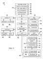
- FIG. 1is a block diagram of an example Unmanned Aerial Vehicle (UAV) architecture for implementing the features and processes described herein.
- UAVcan include a primary computer system 100 and a secondary computer system 102 .
- the UAV primary computer system 100can be a system of one or more computers, or software executing on a system of one or more computers, which is in communication with, or maintains, one or more databases.
- the UAV primary computer system 100can include a processing subsystem 130 including one or more processors 135 , graphics processing units 136 , I/O subsystem 134 , and an inertial measurement unit (IMU) 132 .
- IMUinertial measurement unit
- the UAV primary computer system 100can include logic circuits, analog circuits, associated volatile and/or non-volatile memory, associated input/output data ports, power ports, etc., and include one or more software processes executing on one or more processors or computers.
- the UAV primary computer system 100can include memory 118 .
- Memory 118may include non-volatile memory, such as one or more magnetic disk storage devices, solid-state hard drives, or flash memory. Other volatile memory such as RAM, DRAM, SRAM may be used for temporary storage of data while the UAV is operational.
- Databasesmay store information describing UAV flight operations, flight plans, contingency events, geofence information, component information and other information.
- the UAV primary computer system 100may be coupled to one or more sensors, such as GNSS receivers 150 (e.g., GPS receivers), thermometer 154 , gyroscopes 156 , accelerometers 158 , pressure sensors (static or differential) 152 , current sensors, voltage sensors, magnetometers, hydrometers, and motor sensors.
- the UAVmay use IMU 132 in inertial navigation of the UAV.
- Sensorscan be coupled to the UAV primary computer system 100 , or to controller boards coupled to the UAV primary computer system 100 .
- One or more communication buses, such as a controller area network (CAN) bus, or signal lines,may couple the various sensor and components.
- CANcontroller area network
- the UAV primary computer system 100may use various sensors to determine the UAV's current geo-spatial position, attitude, altitude, velocity, direction, pitch, roll, yaw and/or airspeed and to pilot the UAV along a specified flight path and/or to a specified location and/or to control the UAV's attitude, velocity, altitude, and/or airspeed (optionally even when not navigating the UAV along a specific flight path or to a specific location).
- the flight control module 122handles flight control operations of the UAV.
- the moduleinteracts with one or more controllers 140 that control operation of motors 142 and/or actuators 144 .
- the motorsmay be used for rotation of propellers
- the actuatorsmay be used for flight surface control such as ailerons, rudders, flaps, landing gear and parachute deployment.
- the contingency module 124monitors and handles contingency events. For example, the contingency module 124 may detect that the UAV has crossed a boundary of a geofence, and then instruct the flight control module 122 to return to a predetermined landing location. The contingency module 124 may detect that the UAV has flown or is flying out of a VLOS from a ground operator, and instruct the flight control module 122 to perform a contingency action, e.g., to land at a landing location. Other contingency criteria may be the detection of a low battery or fuel state, a malfunction of an onboard sensor or motor, or a deviation from the flight plan. The foregoing is not meant to be limiting, as other contingency events may be detected. In some instances, if equipped on the UAV, a parachute may be deployed if the motors or actuators fail.
- the mission module 129processes the flight plan, waypoints, and other associated information with the flight plan as provided to the UAV in a flight package.
- the mission module 129works in conjunction with the flight control module 122 .
- the mission modulemay send information concerning the flight plan to the flight control module 122 , for example waypoints (e.g., latitude, longitude and altitude), flight velocity, so that the flight control module 122 can autopilot the UAV.
- waypointse.g., latitude, longitude and altitude
- the UAVmay have various devices connected to the UAV for performing a variety of tasks, such as data collection.
- the UAVmay carry a camera 149 , which can be, for example, a still image camera, a video camera, an infrared camera, or a multispectral camera.
- the UAVmay carry a Lidar, radio transceiver, sonar, and traffic collision avoidance system (TCAS). Data collected by the devices may be stored on the device collecting the data, or the data may be stored on non-volatile memory 118 of the UAV primary computer system 100 .
- TCAStraffic collision avoidance system
- the UAV primary computer system 100may be coupled to various radios, e.g., transceivers 159 for manual control of the UAV, and for wireless or wired data transmission to and from the UAV primary computer system 100 , and optionally a UAV secondary computer system 102 .
- the UAVmay use one or more communications subsystems, such as a wireless communication or wired subsystem, to facilitate communication to and from the UAV.
- Wireless communication subsystemsmay include radio transceivers, infrared, optical ultrasonic and electromagnetic devices.
- Wired communication systemsmay include ports such as Ethernet ports, USB ports, serial ports, or other types of port to establish a wired connection to the UAV with other devices, such as a ground control station (GCS), flight planning system (FPS), or other devices, for example a mobile phone, tablet, personal computer, display monitor, other network-enabled devices.
- GCSground control station
- FPSflight planning system
- the UAVmay use a lightweight tethered wire to a GCS for communication with the UAV.
- the tethered wiremay be affixed to the UAV, for example via a magnetic coupler.
- Flight data logsmay be generated by reading various information from the UAV sensors and operating system 120 and storing the information in computer-readable media (e.g., non-volatile memory 118 ).
- the data logsmay include a combination of various data, such as time, altitude, heading, ambient temperature, processor temperatures, pressure, battery level, fuel level, absolute or relative position, position coordinates (e.g., GPS coordinates), pitch, roll, yaw, ground speed, humidity level, velocity, acceleration, and contingency information.
- position coordinatese.g., GPS coordinates
- the flight data logsmay be stored on a removable medium.
- the mediumcan be installed on the ground control system or onboard the UAV.
- the data logsmay be wirelessly transmitted to the ground control system or to the FPS.
- Modules, programs or instructions for performing flight operations, contingency maneuvers, and other functionsmay be performed with operating system 120 .
- the operating system 120can be a real time operating system (RTOS), UNIX, LINUX, OS X, WINDOWS, ANDROID or other operating system 120 .
- RTOSreal time operating system
- other software modules and applicationsmay run on the operating system 120 , such as a flight control module 122 , contingency module 124 , application module 126 , database module 128 and mission module 129 .
- flight critical functionswill be performed using the UAV primary computer system 100 .
- Operating system 120may include instructions for handling basic system services and for performing hardware dependent tasks.
- the secondary computer system 102may be used to run another operating system 172 to perform other functions.
- the UAV secondary computer system 102can be a system of one or more computers, or software executing on a system of one or more computers, which is in communication with, or maintains, one or more databases.
- the UAV secondary computer system 102can include a processing subsystem 190 of one or more processors 194 , GPU 192 , and I/O subsystem 193 .
- the UAV secondary computer system 102can include logic circuits, analog circuits, associated volatile and/or non-volatile memory, associated input/output data ports, power ports, etc., and include one or more software processes executing on one or more processors or computers.
- the UAV secondary computer system 102can include memory 170 .
- Memory 170may include non-volatile memory, such as one or more magnetic disk storage devices, solid-state hard drives, flash memory. Other volatile memory such a RAM, DRAM, SRAM may be used for storage of data while the UAV is operational.
- the UAV secondary computer system 102can include operating system 172 .
- the operating system 172can be based on real time operating system (RTOS), UNIX, LINUX, OS X, WINDOWS, ANDROID or other operating system.
- RTOSreal time operating system
- other software modules and applicationsmay run on the operating system 172 , such as an application module 174 , database module 176 , mission module 178 and contingency module 180 .
- Operating system 172may include instructions for handling basic system services and for performing hardware dependent tasks.
- the UAVcan include controllers 146 .
- Controllers 146may be used to interact with and operate a payload device 148 , and other devices such as camera 149 .
- Camera 149can include a still-image camera, video camera, infrared camera, multispectral camera, stereo camera pair.
- controllers 146may interact with a Lidar, radio transceiver, sonar, laser ranger, altimeter, TCAS, ADS-B (Automatic dependent surveillance—broadcast) transponder.
- the secondary computer system 102may have controllers to control payload devices.
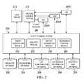
- FIG. 2is a block diagram illustrating an example FPS 200 .
- the various illustrated componentsmay communicate over wired and/or wireless communication channels (e.g., networks, peripheral buses, etc.).
- FPS 200can be a system of one or more computer processors, or software executing on a system of one or more computers.
- the FPS 200can maintain and communicate with one or more databases (e.g., databases 202 - 209 ) storing information describing prior implemented flight plans and information associated with each flight plan (e.g., information describing a UAV, an operator, property/map, mission, database, and so on).
- the databasescan include operator database 202 , operational database 204 , UAV configuration database 206 , UAV mission information database 208 and property and map database 209 .
- the FPS 200can be a system of one or more processors, graphics processors, logic circuits, analog circuits, associated volatile and/or non-volatile memory, associated input/output data ports, power ports, etc., and include one or more software processes executing on one or more processors or computers.
- the FPS 200can be a component of, or be coupled to, one or more user devices 212 or a GCS 213 .
- a user device 212can be a device including one or more processors and configured to send data to and receive data from one or more UAVs 234 A, 234 B and 234 C.
- a GCS 213can be a specialized user device 212 configured to control one or more aspects of a flight of UAVs 234 A, 234 B and 234 C.
- the FPS 200may store, and maintain, flight operation information associated with a UAV. Flight operation information may include configuration information of each UAV, flight mission and planned flight path, operator information, the UAV's precise three-dimensional (3D) location in space, velocity information, UAV status (e.g., health of components included in the UAV), contingency plans, and so on.
- the FPS 200can receive (e.g., from an operator), and determine, information describing a flight plan.
- the FPS 200can provide a flight package 244 associated with the flight plan to a UAV (e.g., UAV 234 A, 234 B, 234 C) to implement. Additionally, the FPS 200 can store flight plan information, flight data log information, job information in the various databases.
- the example FPS 200includes a flight description module 210 that can generate interactive user interfaces (e.g., HTML or XML content for web pages) for rendering on a user device (e.g., user device 212 ).
- the interactive user interfacesmay optionally be transmitted for display to the user device via a wireless network or other communication channel.
- User device 212can receive, from an operator, information describing a flight plan to be performed (e.g., by UAV 234 A, 234 B, or 234 C).
- a user interfacemay be configured to receive, from an operator, location information associated with the flight plan (e.g., an address of a home or property, geospatial coordinates of a structure to be inspected, and so on).
- the flight description module 210can obtain information describing the location.
- the informationcan include property boundaries associated with an address (e.g., boundaries of a home, obtained from a database, or system that stores or configured to access property boundary information), obstacles associated with the location (e.g., nearby trees, electrical towers, telephone poles) and/or other information.
- the flight description module 210can obtain imagery, such as geo-rectified imagery (e.g., satellite imagery), associated with the entered location information.
- the flight description module 210can include some or all of the information describing the location (e.g., the obtained imagery or boundary information) in an interactive user interface to be presented on the user device 212 to an operator.
- the operator of the user device 212may interact with user interfaces to describe a flight boundary geofence (as described further below) for a UAV to enforce.
- the user device 212can receive imagery associated with operator-entered location information, and present one or more geofence shapes layered on the imagery.
- the user interfaceprovides functionality for the operator to select a presented shape (e.g., a polygon), and further provides functionality enabling the operator to drag and/or drop the shape to surround an area of interest in the received imagery to limit allowable locations of a UAV to locations within the shape.
- the user interfacemay allow the user device 212 to receive input (e.g., of a finger or stylus) tracing a particular shape onto a touch-screen display of the user device 212 .
- the flight description module 210can store information describing the trace as a flight boundary geofence. Accordingly, the user device 212 can provide information describing the traced shape to the flight description module 210 (e.g., coordinates associated with the imagery). The flight description module 210 can correlate the traced shape to location information in the real world as illustrated by the imagery (e.g., geospatial coordinates that correspond to the traced shape).
- a user interfacecan enable the operator to describe safe locations for a UAV to begin the flight plan (e.g., a launching location where the UAV takes off from the ground) and end the flight plan (e.g., a landing location where the UAV lands).
- the flight description module 210can analyze the obtained imagery associated with the entered location information, and identify a geometric center of a convex area (e.g., a biggest convex area) within the geofence boundary that does not include obstructions (e.g., trees). For example, the flight description module 210 can determine an open area, such as an open pasture.
- the flight description module 210can obtain topographical information associated with the entered location information, and can detect substantially flat areas (e.g., areas with less than a threshold of variance in height). For instance, the flight description module 210 can determine that an open space (e.g., an open clearing that is substantially flat) is a safe launching location for the UAV to take-off from, and can provide information recommending the open space in an interactive user interface presented on the user device 212 . Additionally, the flight description module 210 can analyze the obtained imagery and locate physical features that are generally known to be safe locations for take-off and landing. For example, the flight description module 210 can determine that a driveway of a home associated with the flight plan is a safe, and can select the driveway as a safe launching and landing location, or can recommend the driveway as a safe launching and landing location.
- substantially flat arease.g., areas with less than a threshold of variance in height.
- an open spacee.g., an open clearing that is substantially flat
- the flight description module 210can analyze
- the flight description module 210can receive (e.g., from a user interface) survey or flight mission information via a flight package, for instance information indicating a particular type of survey for a UAV to perform (e.g., damage inspection, inspection of a vertical structure, or inspection of a rooftop).
- the flight description module 210can receive waypoints for the UAV to travel to, including an order in which the waypoints are to be traveled to, a ranking or importance of each, or a group of, waypoints, and specific actions for the UAV to take while traveling to, or after reaching, each waypoint.
- a user interfacecan optionally enable the operator using the user device 212 to specify that upon reaching a particular waypoint, the UAV is to activate a particular sensor, or other payload devices, such as an infrared camera, a sensor measuring radiation, and so on. Additionally, a user interface can optionally enable the operator to specify transition speeds the UAV is to use when travelling between waypoints, or between particular waypoints.
- operations to be performed at a particular location, or waypointmay be identified by an operator using the FPS 200 or GCS 213 via a user interface.
- the user interfacecan allow an operator to photographically inspect a specified location.
- Operations of the UAVmay be automatically configured by either the FPS 200 or GCS 213 depending on the type of inspection to be performed.
- the flight description module 210can receive information describing, or relevant to, configuration information of a UAV, such as a type of UAV (e.g., fixed-wing, single rotor, multi-rotor, and so on).
- a type of UAVe.g., fixed-wing, single rotor, multi-rotor, and so on.
- the flight description module 210can receive information describing, or relevant to, configuration information of sensors or other payload devices required for the survey or flight mission information, and general functionality to be performed.
- the flight description module 210can then determine recommendations of particular UAVs (e.g., UAVs available to perform the flight plan) that comport with the received information.
- the flight description module 210can determine that, based on the received survey type, a UAV will require particular configuration information, and recommend the configuration information to the operator.
- the flight description module 210can receive information identifying that hail damage is expected, or is to be looked for, and can determine that a UAV that includes particular sensors, and specific visual classifiers to identify hail damage, is needed. For example, the flight description module 210 can determine that a heat and/or thermal imaging sensor that includes specific visual classifiers that can distinguish hail damage from other types of damage (e.g., wind damage, rain damage, and so on) is needed.
- a heat and/or thermal imaging sensorthat includes specific visual classifiers that can distinguish hail damage from other types of damage (e.g., wind damage, rain damage, and so on) is needed.
- the flight description module 210can utilize received survey or flight mission information to determine a flight pattern for a UAV to follow. For instance, the flight description module 210 can determine a path for the UAV to follow between each waypoint (e.g., ensuring that the UAV remains in the geofence boundary). Additionally, the flight description module 210 can determine, or receive information indicating a safe minimum altitude for the UAV to enforce, the safe minimum altitude being an altitude at which the UAV is safe to travel between waypoints. The safe minimum altitude can be an altitude at which the UAV will not encounter obstacles within the geofence boundary (e.g., a height above buildings, trees, towers, poles and so on).
- the safe minimum altitudecan be based on a ground sampling distance (GSD) indicating a minimum resolution that will be required from imagery obtained by the UAV while implementing the flight plan (e.g., based in part on capabilities of an included camera, such as sensor resolution, sensor size, and so on).
- GSDground sampling distance
- the flight description module 210can receive a time that the flight plan is to be performed (e.g., a particular day, a particular time at a particular day, a range of times, and so on). The flight description module 210 can then determine an availability of UAVs and/or operators at the received time(s). For example, the flight description module 210 can obtain scheduling information. Additionally, the flight description module 210 can filter available UAVs according to determined configuration information (e.g., as described above). Optionally, the flight description module 210 can access weather information associated with the received time(s), and determine an optimal time or range of times for the job to be performed.
- a time that the flight plan is to be performede.g., a particular day, a particular time at a particular day, a range of times, and so on.
- the flight description module 210can then determine an availability of UAVs and/or operators at the received time(s). For example, the flight description module 210 can obtain scheduling information. Additionally, the flight description module 210 can filter available U
- a UAV that includes particular sensorscan obtain better real-world information at particular times of day (e.g., at noon on a sunny day can provide better imagery by maximizing image contrast and minimizing the effects of shadows).
- the flight description module 210can determine the flight plan accordingly.
- the FPS 200can provide the determined flight plan as a flight package 244 directly to a UAV (e.g., the UAV 234 A, 234 B or 234 C).
- the FPS 200can provide the flight package 244 to a user device 212 or GCS 213 .
- the user device 212 or GCS 213can modify the flight plan or preserve the flight plan in the flight package 244 as received.
- the user device 212 or GCS 213can transmit the flight package 244 to the UAV 234 A, 234 B or 234 C.
- the flight package 244can include a flight manifest file (e.g., an XML file) identifying necessary application and version information to conduct the flight plan.
- a flight manifest filee.g., an XML file
- the UAVcan be required to execute a particular application (e.g., “app” downloaded from an electronic application store) that provides functionality necessary to conduct the flight plan.
- a particular applicatione.g., “app” downloaded from an electronic application store
- an applicationcan effect a flight plan associated with inspecting vertical structures, and the UAV can be required to execute the application prior to initiation of the flight plan.
- the FPS 200may create a flight plan for automated or partially automated flight of a UAV, taking into consideration structural data to avoid situations where the UAV may fly out of VLOS of a base location.
- the base locationcan include one or more locations of an operator of a UAV.
- the base locationcan be a geospatial position of the user device 212 or a launching location of the UAV.
- the FPS 200may receive, via a user interface, a location for an aerial survey to be conducted by an unmanned aerial vehicle.
- One or more imagesmay be displayed depicting a view of the location.
- the interfaceallows for a selection of a launching location of the UAV. As the images have associated geospatial positions, the FPS 200 can determine an associated latitude/longitude for the launching location.
- the user interfacemay receive an input or selections for one or more flight waypoints. Similar to the launching locations, the flight waypoints having an associated geospatial position.
- the FPS 200may assign altitudes for the flight waypoints, or altitudes for the flight waypoints may be determined by a user, and specific numeric altitudes values may be set.
- the FPS 200may determine based on the launching location and altitude of the one or more flight waypoints whether a flight waypoint may cause a non-VLOS occurrence. From the launching location, a flight plan may be generated using waypoints having an associated latitude and longitude coordinates, and an associated altitude. The FPS 200 may not allow a UAV waypoint where the VLOS from the base location (e.g., the launching location, or an area around the launching location), upon determining that the waypoint would be blocked because of a structure. The FPS 200 may use 3D polygonal data, topographical data or other structure data in generating the flight plan.
- the systemcan use a 3D coordinate system to determine, based on a base location and each waypoint location, whether the UAV would likely enter into a non-VLOS situation.
- the flight planning system 200can then generate flight plan that avoids the non-VLOS situation, and including only the flight waypoints that would not cause a non-VLOS occurrence.
- the flight planning system 200may present, via an interface, one or more recommended launching locations for the UAV that provides an operator an ideal location to obtain a best or maximum VLOS when operating the UAV around a structure.
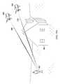
- Lines from multiple points on the flight path, for example from each waypoint, at the flight path altitudecan be computed and projected to various point locations on the ground.
- Point locations on the ground where the lines from the points on the flight path that do not intersect the structuremay be identified as an ideal location for the operator with VLOS vantage point, making the location suitable as a launching location.
- a recommended launching locationmay be selected by the user, and the launching location is used as part of a primary flight plan. Additionally, a backup launching location with a secondary (an alternative) flight plan may be created.
- a physical inspectionproves that the launching location of the primary flight plan is unsuitable. For example, foliage, trees, plants, new structures, etc. not shown in an aerial image used to plan the survey may now be present. These plants and structures may block the UAV from safely ascending to an inspection altitude.
- the operator of the GCS 213may then select the secondary flight plan and launching location to conduct the inspection. Both the primary flight plan, and the secondary flight plans with the alternative launching locations may be transmitted by the flight planning system 200 to the GCS 213 or directly to a UAV. While the FPS 200 is configured to perform operations described for determining a launching location to provide ideal VLOS, the user device 212 or GCS 213 may also perform the operations described for selecting a launching location and waypoints to provide VLOS while operating a UAV.
- the FPS 200may determine a geofence boundary to limit flight of the UAV to a bounded area.
- the user interfacemay display the geofence boundary over one or more location images. Additionally, the FPS 200 may determine a survey area, and set the survey area within the geofence boundary.
- the FPS 200then receives, from a GCS 213 (or directly from the UAV), flight log data and collected sensor data after the UAV has conducted the flight plan.
- a user interface of the FPS 200then displays at least a portion of sensor data collected by the UAV, and information associated with the flight data package.
- the GCS 213may also be used for flight and contingency planning.
- the GCS 213can receive flight plans from the FPS 200 for transmission to the UAV.
- the GCS 213also allows for manual override of a UAV operating in an autopilot mode.
- a flight planmay be transmitted to the UAV either via a wireless or tethered connection.
- the GCS 213is a mobile device, such a laptop, mobile phone, tablet device, with a cellular and other wireless connection for data transmission over the Internet or other network.
- Each of user device 212can be a system of one or more computers, or software executing on a system of one or more computers, which is in communication with, or maintains, one or more databases, e.g., databases, storing information describing UAV flight operations and components.
- Each of user device 212can be a system of one or more processors, graphics processors, logic circuits, analog circuits, associated volatile and/or non-volatile memory, associated input/output data ports, power ports, etc.
- Each of user device 212can include one or more software processes executing on one or more processors or computers.
- the FPS 200may be primarily used to create and transmit a flight package 244 to a UAV or GCS 213
- the UAV or GCS 213can initiate the request for a flight package 244 from the FPS 200 .
- An operatormay take the UAV or GCS 213 to a property location.
- the UAV or GCS 213may then request a flight package, or an updated flight package using a current position of the UAV or GCS 213 .
- the UAV or GCS 213can determine its geospatial position via a GNSS receiver (using GPS, GLONASS, Galileo or Beidou system).
- the UAV or GCS 213can then transmit its location to the FPS 200 , along with other identifying information about the requesting device, such as its unique identifier (UID), or media access control (MAC) address, etc.
- the FPS 200will receive the request, and determine if an updated or changed flight package exists by comparing the device identifier with identifiers in a database storing the new or updated flight package information. If FPS 200 finds a new or updated flight package, then the FPS 200 transmits the flight package from the FPS 200 .
- the UAV or GCS 213can receive the flight package. A confirmation acknowledging receipt of the flight package may then be transmitted from the UAV or GCS 213 to the FPS 200 .
- the FPS 200will then update a database record to indicate that the particular flight package has been received. Moreover, the UAV or GCS 213 can supply the property location, and a new job request can be sent to the FPS 200 . The FPS 200 may create a new flight package for the UAV or GCS 213 .
- a flight planmay be created and transmitted to the UAV.
- the flight planinstructs the UAV with regard to a particular flight path.
- a flight planmay be created using a FPS 200 , or a GCS 213 .
- a flight planinstructs the UAV where it should fly in a 3D space.
- the flight planincludes a series of connected waypoints that define where the UAV should fly and what actions that the UAV should complete during a particular flight.
- the UAVmay have an autopilot flight module operating on a UAV computer system that uses the flight plan to automatically fly the UAV.
- the flight plan informationmay be provided to the GCS 213 and then to the UAV or directly to the UAV, in a flight package 244 comprising the flight plan and other information (such as contingency event instructions).
- a UAV operatormay select a series of geographically-based waypoints and a launching location for the UAV. Based on the waypoints, a flight plan may be constructed allowing the UAV to autonomously navigate itself. In some implementations, the FPS 200 or GCS 213 may automatically define a flight plan based on various criteria, such as an inspection type.
- While the UAV computer system autopilot moduleis navigating the UAV according to a flight plan, certain aspects of the flight pattern may be controlled by the operator's user device 212 .
- the flight plan or patternmay be configured such that for a particular waypoint, a vertical ascent/descent rate, UAV altitude, horizontal UAV rotation, payload gimbal, payload direction, waypoint transition speed, or trigger of a payload sensor may be controlled by the operator.
- the user device 212may have a physical control device such as a toggle or joystick, or virtual control in a user interface that allows the operator to control vertical ascent/descent rate, UAV altitude, UAV attitude, horizontal UAV rotation, payload gimbal, payload direction.
- the user device 212can trigger a payload sensor while conducting the inspection.
- the UAVmay navigate via autopilot to a position over an inspection location.
- An operatorthen can provide input to the user device 212 .
- the user devicemay transmit a signal or information corresponding to the user input to the UAV via radio communication.
- the signal or informationcan control the vertical ascent/descent rate, UAV altitude, UAV attitude, horizontal UAV rotation, payload gimbal, or payload direction, or waypoint transition speed.
- the signal or information tocan trigger a payload sensor to turn on or turn off. This particular mode allows for partial autopilot control and partial or complete manual control of the UAV. Even though the operator may manually control certain aspects of the flight plan, if one has been set, the UAV can remain within a geofence boundary envelope and to remain within VLOS of the operator operating user device 212 .
- the UAVmay be partially manually controlled by an operator using the user device 212 while the UAV is in autopilot mode.
- the UAVmay receive a command from the user device 212 to nudge the UAV in a particular direction.
- the control input of the user device 212causes the user device 212 to send a command to the UAV, instructing the UAV to move slightly, for example between 0.1 to 3 meters, in a particular direction (in an x, y, or z axis, or diagonally).
- the particular distancecan be predetermined, or be variable based on the proximity to a structure. Nudging the UAV allows the operator to move the UAV away from the structure if the operator sees that the UAV flying too close to the structure.
- the nudge commandmay be provided any time to the UAV while it is operating in an auto-piloted mode.
- the UAVshould still enforce geofence boundaries (if one has been set) and not allow a nudge to cause the UAV to move beyond a geofence boundary envelope.
- the FPS 200can include an analysis module 220 , a report generation module 230 and a permission control module 240 .
- the analysis module 220is configured to analyze a flight plan and determine whether a flight path include any sections where a UAV is out of VLOS from a base location, and provides alerts to warn such possible VLOS occurrence.
- the report generation module 230is configured to generate one or more flight reports.
- the flight reportscan include flight data (e.g., path, duration and actions of control surfaces), sensor data (e.g., air pressure, temperature and humidity), and payload data (e.g., information gathered by a payload camera).
- the permission control module 240is configured to impose one or more limits on flights of the UAV. The limits can include, for example, that the UAV shall stay inside or outside an envelope defined by geofences or by geographic coordinates, or that the UAV shall stay within VLOS of a base location (e.g., a location of user device 212 ).
- the user interface 300includes image 302 (e.g., satellite imagery as depicted) of a location entered by the user of the user interface 300 .
- the image 302 included in the user interface 300can be interactive.
- a usercan zoom in and out of the image 302 to target a greater or smaller real-world area.
- the usercan interact with a zoom control, or the user can utilize a touch surface (e.g., a touch screen) to zoom in and out (e.g., the user can pinch to zoom).
- the user interface 300enables the user to select areas on the image 302 that are defined by a user-specified shape.
- the user interface 300can receive a user selection of particular vertices that define the illustrated polygon (e.g., vertices 304 A-E).
- the systemcan shade, or otherwise highlight, the internal portion of the user-specified shape.
- the user interface 300enables the user to select a particular vertex of the illustrated polygon (e.g., vertex 304 A), and drag the shape into existence by moving a finger or stylus on a touch sensitive screen of the user device.
- the user interface 300can receive input for generating a flight path 306 for the UAV to include a launching and landing location 310 .
- the user interface 300may include a menu 308 for creating different representative layers of a flight plan.
- menu 308shows a flight plan specifying a geofence, a photo survey area, a launch/land area, and a base map.
- the menu 308includes a geofence menu item that refers to the geofence as represented by the connected vertices 304 A- 304 E.
- the menu 308includes a photo survey area menu item representing the flight path 306 .
- the menu 308includes a launch/land area menu item representing the launching/landing locations 310 .
- the menu 308includes a base map menu item that represents the base image layer, which includes image 302 .
- the image 302includes a highlighted area that defines a geofence boundary to be enforced by a UAV when implementing a flight plan.
- a geofencecan include a two-dimensional (2D) or 3D location-based boundary.
- a geofencecan be understood as a virtual boundary for a geographic location or a virtual surface around a geographic location in a 3D space.
- the geofence boundarycan be represented on a map as one or more polygonal or rounded shapes, for example, a circle, rectangle, sphere, cylinder, cube, or other shapes or bodies.
- a geofencemay also be a time-based (four-dimensional) virtual boundary where the geofence exists for a particular duration, for example, a number of hours or days, or for a specific time period, for example, from 2:00 PM to 4 PM occurring on certain days, or other periods of time.
- a 3D geofencemay exist in a particular space above ground.
- a geofencemay be represented by latitudinal and longitudinal connected points, or other coordinate systems.
- a geofencemay be created such that the geofence has dynamic aspects where the geofence may increase or decrease in size based on various conditions. For UAV flight operations, geofence structures are received by the UAV and stored in non-volatile memory.
- a 3D geofencemay be created.
- Data representing the flight boundary geofencecan be transmitted to the UAV operating system.
- the exemplary FPS or GCSmay be used to create the geofence and transmit the geofence data structure to the UAV.
- the UAVcan be limited to flight within a flight boundary geofence. If for example, an operator of the UAV in a manually controlled mode attempts to maneuver the UAV outside of the flight boundary geofence, the UAV may detect a contingency condition (e.g., the UAV is about to fly outside of the geofence), and then automatically direct the UAV to return to a specified predetermined landing location. Furthermore, if the UAV is capable of hovering, such as a multi-rotor UAV, the UAV may be inhibited from moving across a flight boundary geofence, or perimeter, of the geofence, and the UAV can be set to hover and not continue past the perimeter of the geofence.
- a contingency conditione.g., the UAV is about to fly outside of the geofence
- the UAVmay be inhibited from moving across a flight boundary geofence, or perimeter, of the geofence, and the UAV can be set to hover and not continue past the perimeter of the geofence.
- the systemcan utilize property information, such as property boundaries, and automatically include a highlighted portion of the image 302 as being a possible flight boundary geofence. For instance, as illustrated in FIG. 3 , portions of the flight boundary geofence defined by connected vertices 304 A, 304 B, 304 C, 304 D and 304 E abut roads included in the real-world geographic area depicted in the image 302 .
- the systemcan determine that the entered location information describes a particular property (e.g., an open clearing that borders the road), and can highlight the particular property.
- the systemcan include a buffer from the property boundaries of the location to ensure that even when facing forces of nature (e.g., in a strong gust of wind), the UAV will remain within the property boundaries.
- Property boundary information from a databasecan be used to create the flight boundary geofence to limit flight of the UAV within the property's boundary.
- the UAVcan then be constrained for flight operations only within this geofence.
- the property information used to create the flight boundary geofencecan be of various data types, for example, parcel polygons, vector, rasterized, shape files or other data types.
- the FPS 200may create the flight boundary geofence based on the property shape data.
- the various data typesideally can have geolocation and/or coordinate information, such as latitudinal/longitudinal points for use in orienting and creating the flight boundary geofence.
- the geofence envelopemay be identical in shape to the property boundary.
- the boundary of the geofencemay be reduced in size.
- the flight boundary geofencemay be reduced in size by a set distance, for example 5 meters, towards a centroid of the property. Reduction of the flight boundary geofence creates a buffer zone. The buffer zone may help avoid an unintentional flyover of an adjacent property boundary.
- the FPSmay display an area with parcel polygonal data. An interface of the FPS may then receive a selection of one or more parcels. The FPS then can use the selections to create one or more jobs, and multiple geofence envelopes. For the multiple parcels, the operator would go to each parcel property, and conduct multiple jobs.
- the user interface 300can be utilized by a UAV operator to indicate waypoints to be traveled to during the flight plan. For instance, the user can select portions of the image 302 to designate as waypoints, and the user interface 300 can be updated to present selectable options associated with each waypoint. As an example, the user can designate an order that each waypoint is to be traveled to, actions the UAV is to take at the waypoint, a transition speed between each or all waypoints, and so on.
- the systemcan determine the flight boundary geofence from the waypoints, such that the geofence perimeter encompasses the waypoints. The determined flight boundary geofence can be presented to the user for review, and the user can modify the boundary by interacting with the user interface 300 .
- the user interface 300can include text provided by the user that describes the flight plan.
- a different usercan access the user interface 300 , and quickly view the determined flight boundary geofence along with text describing the flight plan.
- a usercan quickly describe flight plan information sufficient for a UAV to implement, and other users can quickly view graphical representations of the flight plan (e.g., graphical representation of the flight boundary geofence along with textual data describing the flight plan).
- FIG. 4illustrates an example process 400 of navigating a UAV within visual line of sight.
- a UAV computer systeme.g., UAV primary computer system 100 or UAV secondary computer system 102 , both of FIG. 1
- the UAVmay navigate ( 402 ) in an auto-piloted mode, partially auto-piloted mode, or in a manual mode.
- the UAV processing systemcan determine an in-flight location of the UAV while the UAV is in the air.
- the UAV computer systemcan periodically receive ( 404 ) a geospatial position from a location subsystem of the UAV (e.g., an onboard GNSS receiver or Wi-Fi location module) when the UAV is in the air, and designate the received geospatial position as the in-flight location.
- a location subsystem of the UAVe.g., an onboard GNSS receiver or Wi-Fi location module
- the UAV processing systemdetermines ( 406 ) whether the UAV is about to go beyond or is beyond VLOS of one or more user devices or ground control stations.
- the flight trajectory of the UAVcan be determined by analyzing the direction of flight of the UAV.
- the UAVmay transmit a signal or command to a user device or a GCS.
- the signal or commandcan cause the user device to present an audible or a visual alert indicating the impending or actual non-VLOS occurrence of the UAV.
- the UAVmay display one or more different colored LED lights, or display a repeating visual pattern of lights.
- the UAV computer systemperforms ( 408 ) a contingency action.
- the contingency actioncan include a flight maneuver.
- the UAVcan navigate ( 410 ) to a landing location.
- the user device or GCSmay generate an audible alert of increasing volume as the UAV nears an actual non-VLOS occurrence.
- the UAVmay record its flight path, for example when flying in manual mode.
- the UAVmay periodically record its geospatial position to keep track of its flight path. If the UAV computer system determines that a likely or actual non-VLOS occurrence, then the UAV may conduct a contingency action, where the UAV will backtrack along the recorded flight path until the UAV is within visual line of sight again. In other words, the UAV may navigate along the previous flight path until the VLOS is no longer interrupted between the UAV and the base location.
- the UAVmay backtrack to a point and hover, and wait for additional commands from a ground control station. Backtracking allows the UAV to fly a known safe path.
- the UAVcould also back-track along the known flight path, and then hover at a position where the UAV is again with VLOS. At this point, the operator could move to another location allowing better visibility for flight operations.
- FIG. 5illustrates an example process 500 of navigating a UAV within VLOS.
- a UAV computer systemcan determine a non-VLOS occurrence in relationship to an initial base geospatial location (or simply referred to as a base location).
- One or more processors of the UAV computer systemuser device can determine ( 502 ) a base geospatial location of the UAV.
- a user devicecan transmit to the UAV a geospatial position of the user device.
- the UAV computer systemcan designate the geospatial position as the base location.
- the UAVcan obtain an initial geospatial position (for example, a location of the UAV when the UAV is launching), and designate the initial geospatial position as the base location.
- the UAVmay either navigate ( 504 ) in an auto-piloted mode, partially auto-piloted mode, or in a manual mode.
- the UAV computer systemperiodically receives ( 506 ) a geospatial position from an onboard GNSS receiver when the UAV is in the air, and designates the geospatial position as an in-flight location of the UAV.
- the UAV computer systemdetermines ( 508 ) whether the UAV is about to go beyond or is beyond the VLOS from the base location. In response to determining that the UAV is beyond or is about to go beyond the VLOS from the base location, the UAV computer system performs ( 510 ) a contingency action.
- the UAVmay transmit a signal or command to a user device triggering the user device to present an audible or visual alert indicating a non-VLOS occurrence of the UAV.
- the UAVmay display one or more different colored LED lights, or display a repeating visual pattern of lights.
- the contingency actioncan include a flight maneuver.
- the UAVthen navigates ( 512 ) to a landing location.
- the landing locationcan be the base location or a designated location for UAV recovery.
- FIG. 6illustrates an example process 600 of navigating a UAV within VLOS.
- a user devicedetermines a non-visual line of sight occurrence in relationship to a received geospatial position from the UAV.
- the UAVmay navigate ( 602 ) in an auto-piloted mode, partially auto-piloted mode, or in a manual mode.
- the user deviceobtains ( 604 ) a base location, which can be a geospatial position of the user device, a launching location where the UAV is launched, a designated location or a location of a user.
- the location of the usercan be determined by a location aware device carried by the user.
- the location of the usermay change during flight of the UAV.
- the user deviceperiodically receives ( 606 ) in-flight locations, including geospatial positions from the UAV.
- the in-flight locationcan include latitude, longitude and altitude of the UAV as well as velocity (including speed and direction) of the UAV.
- the UAV computer system or the user devicedetermines ( 608 ) whether the UAV is about to go beyond or is beyond VLOS of the user device.
- the user devicemay perform a contingency action, e.g., by providing ( 610 ) an audible or visual alert indicating a non-VLOS occurrence of the UAV.
- the user devicemay send a signal or command to the UAV (e.g., a contingency operation command).
- the commandcan instruct ( 612 ) the UAV to perform a flight maneuver, e.g., ascending to a higher altitude to fly above a geographic feature to regain (or maintain) VLOS with the user device.
- FIG. 7illustrates an example process 700 of navigating a UAV within visual line of sight of a user device.
- a user deviceperiodically transmits a geospatial position of the user device to a UAV.
- the UAVmay navigate ( 702 ) in an auto-piloted mode, partially auto-piloted mode, or in a manual mode.
- the user deviceperiodically obtains ( 704 ) a geospatial position of the user device.
- the geospatial position of the user devicecan be designated as a base location.
- the user devicecan transmit the base location to the UAV ( 706 ).
- the user devicereceives ( 708 ) an indication that the UAV is about to fly beyond, or has actually flown beyond, VLOS of the base location.
- the user devicemay perform a contingency action. For example, the user device can provide ( 710 ) an audible or visual alert indicating a non-VLOS occurrence of the UAV. In response to the likely or actual non-VLOS occurrence, the user device may send a command to the UAV (e.g., a contingency operation command, or a flight maneuver command directing the UAV to ascend to a higher altitude).
- a command to the UAVe.g., a contingency operation command, or a flight maneuver command directing the UAV to ascend to a higher altitude.
- FIG. 8is a flowchart of an example process 800 for navigating a UAV within visual line of sight.
- Process 800can be performed by one or more computer processors.
- the computer processorscan be components of a user device or a UAV computer system.
- the user devicecan include a GCS.
- the one or more processorscan obtain ( 802 ) a base location of a UAV.
- the base locationcan be a launching location where the UAV took off ground, a geospatial position of the user device, or a geospatial position of an operator of the UAV.
- the user devicecan be a location-aware device equipped with, or coupled to, a location system (e.g., a GNSS processor).
- the user devicecan include a GCS.
- the operator of the UAV and the user devicemay move around during flight of the UAV. Accordingly, a base location can move.
- the one or more processorscan track a moving base location by receiving the location of the user device periodically.
- the base locationcan be determined by the UAV, by the user device, or by another device providing a location (e.g., a location-aware wearable device carried by the operator of the UAV and connected to the user device by a wired or wireless connection).
- the base location that is using the UAV launching locationcan be optionally offset by a standard height, or an input of the height of the operator. Since the launch location will be at ground level, the geo-spatial base location can be increased in altitude to add the height of the operator, or an average height, for example 5 feet, 5 inches. This correction allows for a more accurate visual line of sight for the operator.
- the one or more processorscan obtain ( 804 ) an in-flight location of the UAV.
- the in-flight location of the UAVcan be a geospatial position of the UAV determined by a location subsystem of the UAV when the UAV is in flight.
- the geospatial position of the UAVcan be provided by a GNSS processor onboard the UAV.
- the one or more processorscan create a point cloud of a structure, and determine the in-flight location of the UAV using the point cloud.
- the UAVcan perform a scan of geographic features while in flight, and create a point cloud of the geographic features based on the scan. The UAV can then determine an in-flight location relative to the geographic features using the point cloud.
- the one or more processorscan determine ( 806 ) or predict that a VLOS between the base station and the in-flight location is or will be interrupted. Determining or predicting that the VLOS between the base station and the in-flight location is or will be interrupted can be based on communication between the UAV and a user device, based on a geospatial relationship between the base location, the in-flight location and geographic features, or based on a combination of both. In various implementations, the determination or prediction can be performed on the user device or on the UAV. For example, the UAV can submit the in-flight position to a user device periodically.
- the one or more processors onboard the user devicecan make the determination or prediction based on the base location and the in-flight location received from the UAV. Likewise, the user device can submit the base location to the UAV. The one or more processors onboard the UAV can make the determination or prediction based on the in-flight location of the UAV and the received base location.
- a user devicecan provide updates on the base location to the UAV periodically.
- the user devicemay have a GNSS-enabled receiver.
- the user devicemay periodically obtain geospatial positions of the user device. For example, an operator of the user device may stand at a particular location.
- the user devicecan obtain a first geospatial position, and provide the first geospatial position as a base location to the UAV. After launch of the UAV, the operator may move around to obtain a better vantage point to view while the UAV is in flight.
- the user devicemay periodically obtain a new geospatial position, and provide the position to the UAV as updated based location.
- two or more user devicesmay be used to spot the UAV.
- the base locationmay include multiple geospatial positions of the multiple user devices.
- a second ground operatoror spotter
- This second user devicemay obtain a geospatial position, and transmit the geospatial position to the UAV, and optionally to the first user device that is used to control the UAV.
- Both the geospatial position of the first user device and the geospatial position of the second user devicecan be designated as the base location.
- the one or more processorscan determine that the UAV is beyond VLOS of the base location upon determining that the UAV is out of VLOS of both the first user device and the second user device.
- the location of the user device as the base locationcan be optionally offset by a predetermined height value, or an input of the height of the operator. Since the location of the user device will be above ground level, but below eye level of the operator, the geo-spatial base location altitude of the user device can be increased in by an amount to more accurately reflect the actual visual height of the operator. This correction allows for a more accurate visual line of sight for the operator to the UAV.
- determining or predicting that the VLOS between the base station and the in-flight location is or will be interruptedis based on communication between the UAV and a user device.
- the UAVcan send a UAV signal (e.g., an optical signal such as visible or infrared light signal) periodically.
- the user devicecan respond with a light signal or a wireless signal acknowledging receipt of the UAV signal.
- the UAVmay determine that the VLOS is interrupted upon determining that the UAV has not received the acknowledging signal after a threshold period of time has passed since the UAV sent the original signal.
- the role of the UAV and user devicecan be reversed. For example, the original signal may be sent by the user device.
- the one or more processorscan determine or predict that the VLOS between the base location and the in-flight location is interrupted when a signal strength (RSSI) of a wireless signal received by the user device from the UAV (or by the UAV from the user device) falls below a threshold.
- RSSIsignal strength
- the UAVmay increase the frequency or intensity of the UAV signal based on the altitude of the UAV, or a distance above the height of a structure, or how imminent the VLOS will be interrupted.
- the UAVcan increase the frequency or intensity of the UAV signal upon determining that an interruption of the VLOS is temporally or geospatially imminent.
- a UAVcan include functionality to actively determine whether it is within VLOS of an operator located at the base location.
- the UAVcan utilize cameras to actively ensure that the operator is within VLOS of the UAV.
- the UAVcan be configured to visually detect an object associated with the operator.
- the operatorcan wear an object (e.g., an object having a particular shape, color or other visual property, an object that outputs particular electromagnetic radiation, and so on).
- the UAVcan ensure that the object is within VLOS with the UAV.
- determining or predicting that the VLOS between the base station and the in-flight location is or will be interruptedis based on geospatial relationship between the base location and the in-flight location.
- the one or more processorscan determine or predict the interruption using a database of three-dimensional geographic features.
- the one or more processorscan determine that the UAV has entered a geofence that corresponds to a space that is located behind a building from a viewpoint of the based location. In response, the one or more processors can determine that the VLOS is interrupted.
- a 3D geofencecan be utilized to force a UAV to maintain VLOS with an operator's user device.
- the 3D geofencecan be generated based on a prior 3D map of an inspected geographic area.
- a processorcan use a hidden surface determination or occlusion analysis to determine a location of the operator.
- Other methodscan be utilized to maintain VLOS without a prior 3D map (e.g., the UAV or a cloud system can actively determine a 3D geofence as the UAV traverses an inspectable area).
- One or more 3D geofencesmay be used by a user device or the cloud system, and may be used by the UAV during flight.
- the databasestores a topographical map of the 3D geographic features.
- the one or more processorscan determine a line between the base location and the in-flight location, and determine whether any of the 3D geographic features intersects that line.
- the topographical mapcan indicate a respective height of each 3D feature.
- the one or more processorscan identify features along the line between the base location and the in-flight location.
- the one or more processorscan determine or predict that the VLOS is interrupted upon determining that an altitude of the UAV is below a height of a feature along the line.
- structural polygonal datacan be used to determine at least a height and physical formation of one or more natural or man-made structures (e.g., hills, trees or buildings).
- the structural polygonal datamay be downloaded by the UAV from a server.
- the UAVmay creating a point-cloud using real-time Lidar (or other point measurement device such as Leddar or Sonar) observations.
- the point-cloudthen can be used to determine where the UAV is located in a 3D space in relationship to the base location or in relationship to the structures.
- the one or more processorscan instruct ( 808 ) the UAV to perform a contingency action.
- the contingence actioncan include providing a command to a controller to control at least one of a motor or actuator of the UAV to move a control surface of the UAV, where movement of the control surface causes the UAV to land at a landing location or to fly to a position that is within VLOS of a ground control station of the UAV.
- the contingence actioncan include navigating the UAV to a landing location (e.g., the base location, a pre-specified location or a nearest feasible location that is within the VLOS of the user device).
- the contingency actioncan include navigating the UAV to hold at a waypoint prior to descending.
- the contingency actioncan include navigating the UAV to ascend to a higher altitude until the UAV determines that the UAV is within VLOS of the base location.
- the contingency actioncan include logging the geospatial coordinates of the flight of the UAV, and reversing the flight of the UAV along the previous flight path using the recorded geospatial coordinates of the UAV, or flying back to previous waypoints of a flight plan.
- the contingency actioncan include reversing the flight of the UAV until the UAV reaches a point where the UAV is within VLOS of the base position.
- the previous examplesare not meant to be limiting. Additional and alternative contingency actions are possible.
- the one or more processorscan cause a user device to perform a contingency action.
- the one or more processorscan present an alert on a user device controlling the UAV.
- the alertcan include an instruction of moving the user device to a new base location that is in VLOS with the UAV, or an instruction on how to manually navigate the UAV back to in VLOS of the operator.
- the ground control stationmay provide an audible or visual alert that the UAV is about to go beyond visual line of sight, or that the UAV has gone beyond visual line of sight.
- the UAValso may display one or more different colored LEDs or other lights, or a repeating a visual pattern of lights.
- FIG. 9Aillustrates example operations of maintaining a UAV 908 within visual line of sight from a base location.
- an operatorcontrols operations of the UAV 908 using a user device 902 .
- User device 902can be a GCS.
- the operatoris flying the UAV 908 around the structure 904 .
- Line 906represents the situation when the UAV 908 is within VLOS of the base location.
- the base locationis a geospatial position of the user device 902 .
- Line 910represents the situation when the UAV 908 is about to go beyond, or has gone beyond VLOS of the base location.
- a computer processorcan cause the UAV 908 or the user device 902 to perform a contingency action. For example, the computer processor can instruct the UAV 908 to land at a landing location or ascend to a higher altitude.
- a database onboard UAV 908 or onboard user device 902can store a 3D representation of structure 904 .
- a processorcan determine that line 910 is interrupted base on the base location, an in-flight location of UAV 908 , and the 3D representation of structure 904 .
- the 3D representation of structure 904can be downloaded to the database from a server.
- the user device 902 or the UAV 908may individually, or together as part of a system, determine whether the UAV 908 is about to, or has encountered, a non-VLOS condition.
- the user device 902 or the UAV 908may determine that the UAV 908 is approaching a position beyond VLOS of the base location (e.g., geospatial position of the user device 902 ).
- One or more processors of the user device 902 or the UAV 908may use three geospatial points to determine or predict the non-VLOS occurrence.
- the one or more processorscan use a 3D coordinate system, such as a 3D Cartesian coordinate system, cylindrical coordinate system, or spherical coordinate system to make the determination or prediction.
- a 3D coordinate systemsuch as a 3D Cartesian coordinate system, cylindrical coordinate system, or spherical coordinate system to make the determination or prediction.
- Cartesian coordinate systemsuch as a 3D Cartesian coordinate system, cylindrical coordinate system, or spherical coordinate system to make the determination or prediction.
- a first point P 1 (x,y,z)can be a point defining a place near the ground representing the base location.
- the first point P 1 (x,y,z)can represent, for example, a geospatial position of a ground operator.
- the first point P 1can correspond to the geospatial position of the launching location of the UAV 908 , or a location of the user device 902 .
- the user device 902can periodically update the base location when the operator of the user device is moving around.
- Geospatial datacan be in a WGS-84 format and converted using the Haversine Formula. The geospatial data including altitude information can be used to determine the Cartesian coordinate points.
- a second point P 2 (a,b,c)is a point defining an in-flight location, which is a location of the UAV 908 flying in the air.
- a line between P 1 (x,y,z) and P 2 (a,b,c) in the Cartesian coordinate systemcan be determined.
- Various polygon structures, 3D geofences, or other topographical datacan be used to determine if the UAV 908 is about to enter a non-VLOS condition.
- a polygonal representation of structure 904may be expressed in the Cartesian coordinate system.
- the one or more processorscan then determine that the UAV 908 is in a non-VLOS condition relative to the base location.
- the UAV or user device 902can calculate a particular distance between the line and each polygonal structure. Upon determining that the distance is within a threshold distance or value, the one or more processors can then predict that the UAV 908 is close to entering in a non-VLOS condition.
- the base locationcan be represented by a volumetric shape, such as a cube, sphere, cylinder or other volumetric shape.
- the base locationcan be represented as a two-dimensional boundary around a geospatial position of the user device or a launching location of a UAV.
- the in-flight location of the UAV in the aircan be represented by a volumetric shape, or a 2D shape.
- Various formulaecan be used to compare the various points of the volumetric or 2D shapes.
- FIG. 9Billustrates example operations of maintaining a UAV within VLOS based on 3D geofences.
- An operator with a user device 922is flying UAV 927 above a 3D geofence 924 .
- User device 922can include a GCS.
- Line 926represents the situation where the UAV 927 is within VLOS of a base location, which is a geospatial position of the user device 922 .
- an operator with a user device 922is flying UAV 928 above the 3D geofence 930 .
- UAV 928is within VLOS of the base location, as represented by line 932 .
- Line 931represents the UAV 928 about to go, or going beyond VLOS of the base location.
- a computer processorcan cause the UAV 928 or the user device 922 to perform a contingency action. For example, the computer processor can instruct the UAV 928 to slow down and land at a landing location or ascend to a higher altitude.
- the UAV 928may be prevented from flying more than a threshold distance from a signal source, e.g., the user device 922 controlling flight of the UAV 928 .
- a signal sourcee.g., the user device 922 controlling flight of the UAV 928 .
- the one or more processors of a UAV computer systemdetermines that strength of signals from the signal source falls below a threshold value, the UAV computer system can perform a contingency action.
- the one or more processors of the UAV computerscan direct the UAV 928 to perform a flight maneuver (such as ascended to a higher altitude) by sending a command to a controller of a motor or actuator to increase or decrease airspeed or to move a flight surface, if the determined signal strength falls below a threshold value.
- a flight maneuversuch as ascended to a higher altitude
- the signal sourcecan be one or more of a cellular radio signal, a wireless router signal, a microwave radio signal, an FM transmitter signal, an AM transmitter signal or a Bluetooth signal.
- the UAV 928may transmit a UAV signal to the user device 922 confirming that the UAV is within visual line of sight.
- the user device 922may transmit a signal to the UAV 928 confirming that the UAV 928 is within VLOS of user device 922 .
- the UAV 928can use an optical sensor to determine the ambient visual conditions. For example, the optical sensor can detect fog, smoke, cloud, dust or lighting conditions. The UAV 928 can determine a visibility distance based on the visual conditions. Upon determining that the visibility distance falls below a threshold value, then the UAV 928 can determine that the UAV 928 is flying in non-visual flight conditions. In response, the UAV 928 can trigger a contingency action.
- the UAV 928may detect nearby clouds with various sensors, and the UAV computer system of UAV 928 may maintain the UAV 928 vertically and horizontally separated from the detected cloud by a fixed or variable distance. For example, the UAV 928 may maintain at least a horizontal and vertical distance of 500 feet from the detected cloud.
- the user device 922 or the UAV 928can receive weather updates for current weather conditions.
- the UAV 928 , or the user device 922may determine, based on the received weather updates, that in the local area the UAV 928 will not be able to fly under visual flight conditions. Additionally, the user device 922 or UAV 928 can determine a cloud ceiling level from the weather updates.
- the UAV 928can restrict an altitude of the UAV 928 to an altitude that is lower than the ceiling by a separation distance. For example, upon determining that the cloud ceiling is 1000 feet, the UAV 928 may be restricted to flight up to 500 feet, given a separation distance of 500 feet.
- the separation distance from the cloud ceilingmay be a fixed distance, or may be variable based on the ceiling height, where a higher cloud ceiling corresponds to a larger separation distance.
- a 2000-foot cloud ceilingcan correspond to a separation distance of 600 feet
- a 1500-foot cloud ceilingcan correspond to a separation distance of 500 feet.
- the processes and operationsare described above in terms of a processor one or more processors.
- the processor or processorscan be onboard a UAV, onboard a user device, or part of a cloud-based processing system.
- a user devicecan be designated as a GCS and perform functions of a GCS.
- a user device and a UAV computer systemcan be designated as a FPS and perform functions of an FPS.
- functions of both the GCS and FPScan be performed by a cloud-based processing system.
- a primary operatorcan control the UAV with a GCS, and one or more additional devices that are in communication with the UAV (or directly with the GCS) can cooperatively operate to determine if the UAV is beyond visual line of sight of each or all of the devices. So long as the UAV is determined to be within visual line of sight of at least one of the devices using the techniques described herein, then a contingency event would not be generated.
- the UAVcould receive a base location from a primary operator's GCS and a spotter's user device.
- the primary operatorcould be positioned at a location where the operator's GCS may lose visual line of sight of the UAV.
- the spotter's user devicemay also provide a base location to the UAV, or transmit the base location to the operator's GCS. If the visual line of sight between UAV's in-flight geo-spatial location and at least one of the devices (e.g., the user device or GCS), the UAV would be considered to be within visual line of sight, and no contingency operation would be initiated. However, if the UAV's visual line of sight for both the operator's GCS and the user device is interrupted, then a contingency operation would be conducted as described herein.
- UAVsmay be used to implement the inventions described herein (for example, a fixed wing airplane, helicopter, a multi-rotor vehicle (e.g., a quad-copter in single propeller and coaxial configurations), a vertical takeoff and landing vehicle, lighter than air aircraft).
- a multi-rotor vehicle in a coaxial configurationmay use the same propeller pitch and diameter propellers, use different pitch and diameter propellers, or variable pitch propellers.
- UAVssuch as drones, un-operated aerial vehicles, remotely operated aircraft, unmanned aircraft systems, any aircraft covered under Circular 328 AN/190 classified by the International Civil Aviation Organization, and so on.
- sensorswhich are included in the general term payload (e.g., any hardware, software, module, and so on, that is not critical to the flight operation of the UAV), can include any device that captures real-world information, including cameras, radiation measuring instruments, distance detectors such as Lidar, and so on.
- code modulesexecuted by one or more computer systems or computer processors comprising computer hardware.
- the code modulesmay be stored on any type of non-transitory computer-readable medium or computer storage device, such as hard drives, solid-state memory, optical disc, and/or the like.
- the systems and modulesmay also be transmitted as generated data signals (for example, as part of a carrier wave or other analog or digital propagated signal) on a variety of computer-readable transmission mediums, including wireless-based and wired/cable-based mediums, and may take a variety of forms (for example, as part of a single or multiplexed analog signal, or as multiple discrete digital packets or frames).
- the processes and algorithmsmay be implemented partially or wholly in application-specific circuitry.
- the results of the disclosed processes and process stepsmay be stored, persistently or otherwise, in any type of non-transitory computer storage such as, for example, volatile or non-volatile storage.
- User interfaces described hereinare optionally presented (and user instructions may be received) via a user computing device using a browser, other network resource viewer, a dedicated application, or otherwise.
- Various features described or illustrated as being present in different embodiments or user interfacesmay be combined into the same embodiment or user interface.
- Commands and information received from the usermay be stored and acted on by the various systems disclosed herein using the processes disclosed herein. While the disclosure may reference to a user hovering over, pointing at, or clicking on a particular item, other techniques may be used to detect an item of user interest. For example, the user may touch the item via a touch screen, or otherwise indicate an interest.
- the user interfaces described hereinmay be presented on a user terminal, such as a laptop computer, desktop computer, tablet computer, smartphone, virtual reality headset, augmented reality headset, or other terminal type.
- the user terminalsmay be associated with user input devices, such as touch screens, microphones, touch pads, keyboards, mice, styluses, cameras, etc. While the foregoing discussion and figures may illustrate various types of menus, other types of menus may be used. For example, menus may be provided via a drop down menu, a toolbar, a pop up menu, interactive voice response system, or otherwise.
- engineand “module” as used herein refer to logic embodied in hardware or firmware, or to a collection of software instructions, possibly having entry and exit points, written in a programming language, such as, for example, Java, Lua, C or C++.
- a software modulemay be compiled and linked into an executable program, installed in a dynamic link library, or may be written in an interpreted programming language such as, for example, BASIC, Perl, or Python. It will be appreciated that software modules may be callable from other modules or from themselves, and/or may be invoked in response to detected events or interrupts.
- Software modules configured for execution on computing devicesmay be provided on a computer readable medium, such as a compact disc, digital videodisc, flash drive, or any other tangible medium.
- Such software codemay be stored, partially or fully, on a memory device of the executing computing device.
- Software instructionsmay be embedded in firmware, such as an EPROM.
- hardware modulesmay be comprised of connected logic units, such as gates and flip-flops, and/or may be comprised of programmable units, such as programmable gate arrays or processors.
- the modules described hereinare preferably implemented as software modules, but may be represented in hardware or firmware. Generally, the modules described herein refer to logical modules that may be combined with other modules or divided into sub-modules despite their physical organization or storage.
- Electronic data sourcescan include databases, volatile/non-volatile memory, and any memory system or subsystem that maintains information.
- a general-purpose computercomprising one or more processors should not be interpreted as excluding other computer components, and may possibly include such components as memory, input/output devices, and/or network interfaces, among others.
Landscapes
- Engineering & Computer Science (AREA)
- Aviation & Aerospace Engineering (AREA)
- Physics & Mathematics (AREA)
- General Physics & Mathematics (AREA)
- Radar, Positioning & Navigation (AREA)
- Remote Sensing (AREA)
- Automation & Control Theory (AREA)
- Theoretical Computer Science (AREA)
- Astronomy & Astrophysics (AREA)
- Computer Networks & Wireless Communication (AREA)
- Signal Processing (AREA)
- Multimedia (AREA)
- Control Of Position, Course, Altitude, Or Attitude Of Moving Bodies (AREA)
- Navigation (AREA)
- Traffic Control Systems (AREA)
Abstract
Description
Claims (29)
Priority Applications (5)
| Application Number | Priority Date | Filing Date | Title |
|---|---|---|---|
| US15/094,802US9588516B1 (en) | 2016-02-08 | 2016-04-08 | Unmanned aerial vehicle visual line of sight control |
| PCT/US2017/018863WO2017147142A1 (en) | 2016-02-22 | 2017-02-22 | Unmanned aerial vehicle visual line of sight control |
| US15/449,846US11189180B2 (en) | 2016-02-08 | 2017-03-03 | Unmanned aerial vehicle visual line of sight control |
| US17/512,323US11854413B2 (en) | 2016-02-08 | 2021-10-27 | Unmanned aerial vehicle visual line of sight control |
| US18/394,152US12400552B2 (en) | 2016-02-08 | 2023-12-22 | Unmanned aerial vehicle visual line of sight control |
Applications Claiming Priority (3)
| Application Number | Priority Date | Filing Date | Title |
|---|---|---|---|
| US201662292783P | 2016-02-08 | 2016-02-08 | |
| US201662298429P | 2016-02-22 | 2016-02-22 | |
| US15/094,802US9588516B1 (en) | 2016-02-08 | 2016-04-08 | Unmanned aerial vehicle visual line of sight control |
Related Child Applications (1)
| Application Number | Title | Priority Date | Filing Date |
|---|---|---|---|
| US15/449,846ContinuationUS11189180B2 (en) | 2016-02-08 | 2017-03-03 | Unmanned aerial vehicle visual line of sight control |
Publications (1)
| Publication Number | Publication Date |
|---|---|
| US9588516B1true US9588516B1 (en) | 2017-03-07 |
Family
ID=58162231
Family Applications (7)
| Application Number | Title | Priority Date | Filing Date |
|---|---|---|---|
| US15/088,005AbandonedUS20180025649A1 (en) | 2016-02-08 | 2016-03-31 | Unmanned aerial vehicle privacy controls |
| US15/088,042ActiveUS10762795B2 (en) | 2016-02-08 | 2016-03-31 | Unmanned aerial vehicle privacy controls |
| US15/094,802ActiveUS9588516B1 (en) | 2016-02-08 | 2016-04-08 | Unmanned aerial vehicle visual line of sight control |
| US15/449,846ActiveUS11189180B2 (en) | 2016-02-08 | 2017-03-03 | Unmanned aerial vehicle visual line of sight control |
| US17/008,344ActiveUS11361665B2 (en) | 2016-02-08 | 2020-08-31 | Unmanned aerial vehicle privacy controls |
| US17/512,323ActiveUS11854413B2 (en) | 2016-02-08 | 2021-10-27 | Unmanned aerial vehicle visual line of sight control |
| US18/394,152ActiveUS12400552B2 (en) | 2016-02-08 | 2023-12-22 | Unmanned aerial vehicle visual line of sight control |
Family Applications Before (2)
| Application Number | Title | Priority Date | Filing Date |
|---|---|---|---|
| US15/088,005AbandonedUS20180025649A1 (en) | 2016-02-08 | 2016-03-31 | Unmanned aerial vehicle privacy controls |
| US15/088,042ActiveUS10762795B2 (en) | 2016-02-08 | 2016-03-31 | Unmanned aerial vehicle privacy controls |
Family Applications After (4)
| Application Number | Title | Priority Date | Filing Date |
|---|---|---|---|
| US15/449,846ActiveUS11189180B2 (en) | 2016-02-08 | 2017-03-03 | Unmanned aerial vehicle visual line of sight control |
| US17/008,344ActiveUS11361665B2 (en) | 2016-02-08 | 2020-08-31 | Unmanned aerial vehicle privacy controls |
| US17/512,323ActiveUS11854413B2 (en) | 2016-02-08 | 2021-10-27 | Unmanned aerial vehicle visual line of sight control |
| US18/394,152ActiveUS12400552B2 (en) | 2016-02-08 | 2023-12-22 | Unmanned aerial vehicle visual line of sight control |
Country Status (1)
| Country | Link |
|---|---|
| US (7) | US20180025649A1 (en) |
Cited By (52)
| Publication number | Priority date | Publication date | Assignee | Title |
|---|---|---|---|---|
| US10032078B2 (en) | 2014-01-10 | 2018-07-24 | Pictometry International Corp. | Unmanned aircraft structure evaluation system and method |
| WO2018178758A1 (en)* | 2017-03-31 | 2018-10-04 | Telefonaktiebolaget Lm Ericsson (Publ) | Enhanced flight plan for unmanned traffic aircraft systems |
| WO2018187889A1 (en)* | 2017-04-09 | 2018-10-18 | 深圳市大疆创新科技有限公司 | Flight processing method and control apparatus |
| US20180312274A1 (en)* | 2017-04-27 | 2018-11-01 | Qualcomm Incorporated | Environmentally Aware Status LEDs for Use in Drones |
| US20180359792A1 (en)* | 2017-06-13 | 2018-12-13 | Rumfert, Llc | WIRELESS REAL-TIME DATA-LINK SENSOR METHOD AND SYSTEM FOR SMALL UAVs |
| US10157546B2 (en)* | 2016-06-10 | 2018-12-18 | ETAK Systems, LLC | Anti-drone flight protection systems and methods |
| CN109388148A (en)* | 2017-08-10 | 2019-02-26 | 松下电器(美国)知识产权公司 | Moving body, control method and control program |
| EP3489929A1 (en)* | 2017-11-24 | 2019-05-29 | Thales | Electronic system for remote control of drones, associated method and computer program |
| US10319246B2 (en)* | 2015-09-29 | 2019-06-11 | Airbus Defence and Space GmbH | Unmanned aerial vehicle and method for safely landing an unmanned aerial vehicle |
| US10356367B2 (en)* | 2016-11-30 | 2019-07-16 | Kabushiki Kaisha Toyota Chuo Kenkyusho | Blind spot coverage device, control device, and recording medium storing distributed control program for moving body |
| CN110262540A (en)* | 2018-03-12 | 2019-09-20 | 杭州海康机器人技术有限公司 | The method and apparatus that flight control is carried out to aircraft |
| USD861968S1 (en) | 2017-10-06 | 2019-10-01 | Talon Aerolytics (Holding), Inc. | Strobe component |
| US10455520B2 (en) | 2017-03-30 | 2019-10-22 | At&T Intellectual Property I, L.P. | Altitude based device management in a wireless communications system |
| US10460279B2 (en)* | 2016-06-28 | 2019-10-29 | Wing Aviation Llc | Interactive transport services provided by unmanned aerial vehicles |
| US10520943B2 (en)* | 2016-08-12 | 2019-12-31 | Skydio, Inc. | Unmanned aerial image capture platform |
| EP3598420A1 (en)* | 2018-07-20 | 2020-01-22 | Aurora Flight Sciences Corporation | Flight control systems for aerial vehicles and related methods |
| EP3598419A1 (en)* | 2018-07-20 | 2020-01-22 | Thales | Flight control from a non-avionic device |
| EP3602519A1 (en)* | 2017-03-31 | 2020-02-05 | Telefonaktiebolaget LM Ericsson (PUBL) | Methods and systems for using network location services in a unmanned aircraft systems traffic management framework |
| US10684619B2 (en)* | 2015-09-04 | 2020-06-16 | Panasonic Intellectual Property Corporation Of America | Notification method, notification device, and terminal |
| US10735908B2 (en)* | 2017-03-22 | 2020-08-04 | Nokia Technologies Oy | Systems and apparatuses for detecting unmanned aerial vehicle |
| US20200257003A1 (en)* | 2017-10-30 | 2020-08-13 | Goertek Inc. | Unmanned aerial vehicle communication method and device and unmanned aerial vehicle |
| US10762795B2 (en) | 2016-02-08 | 2020-09-01 | Skydio, Inc. | Unmanned aerial vehicle privacy controls |
| US10795353B2 (en) | 2014-06-19 | 2020-10-06 | Skydio, Inc. | User interaction paradigms for a flying digital assistant |
| US10816967B2 (en) | 2014-06-19 | 2020-10-27 | Skydio, Inc. | Magic wand interface and other user interaction paradigms for a flying digital assistant |
| US20210034078A1 (en)* | 2017-12-27 | 2021-02-04 | Intel Corporation | Dynamic generation of restricted flight zones for drones |
| US10952113B2 (en) | 2017-09-05 | 2021-03-16 | Telefonaktiebolaget Lm Ericsson (Publ) | Planned continuity of unmanned aerial vehicle (UAV) link connectivity in UAV traffic management systems |
| US11029707B2 (en)* | 2016-07-29 | 2021-06-08 | SZ DJI Technology Co., Ltd. | Moving object, moving object control method, moving object control system, and moving object control program |
| US11106225B2 (en)* | 2017-09-01 | 2021-08-31 | Iain Matthew Russell | Unmanned aerial vehicles |
| US11157155B2 (en)* | 2018-08-16 | 2021-10-26 | Autel Robotics Europe Gmbh | Air line displaying method, apparatus and system, ground station and computer-readable storage medium |
| US11166208B2 (en) | 2017-05-05 | 2021-11-02 | Telefonaktiebolaget Lm Ericsson (Publ) | Methods and systems for using an unmanned aerial vehicle (UAV) flight path to coordinate an enhanced handover in 3rd generation partnership project (3GPP) networks |
| US11242143B2 (en) | 2016-06-13 | 2022-02-08 | Skydio, Inc. | Unmanned aerial vehicle beyond visual line of sight control |
| US20220068145A1 (en)* | 2020-08-26 | 2022-03-03 | Michael A. Cummings | System, apparatus and method for improved airport and related vehicle operations and tracking |
| US11294369B2 (en)* | 2016-11-30 | 2022-04-05 | Samsung Electronics Co., Ltd. | Unmanned aerial vehicle and method for controlling flight of the same |
| US11295458B2 (en) | 2016-12-01 | 2022-04-05 | Skydio, Inc. | Object tracking by an unmanned aerial vehicle using visual sensors |
| US11353892B2 (en)* | 2016-10-17 | 2022-06-07 | X Development Llc | Drop-off location planning for delivery vehicle |
| US11445510B2 (en) | 2017-07-10 | 2022-09-13 | Telefonaktiebolaget Lm Ericsson (Publ) | Optimization of radio resource allocation based on unmanned aerial vehicle flight path information |
| US11474539B2 (en) | 2017-04-14 | 2022-10-18 | Telefonaktiebolaget Lm Ericsson (Publ) | Optimal unmanned aerial vehicle flight route planning based on quality-of-service requirements for data, telemetry, and command and control requirements in 3GPP networks |
| US11485493B2 (en) | 2017-12-29 | 2022-11-01 | Telefonaktiebolaget Lm Ericsson (Publ) | Using a cellular interface for Unmanned Aerial Vehicle communications |
| US20220394495A1 (en)* | 2021-06-02 | 2022-12-08 | Verizon Patent And Licensing Inc. | System and method for wireless equipment deployment |
| JP7270199B1 (en) | 2022-10-13 | 2023-05-10 | 九州電力株式会社 | Drone Visible Area Display System |
| US11657720B2 (en) | 2018-03-30 | 2023-05-23 | Telefonaktiebolaget Lm Ericsson (Publ) | Network coverage and policy information generation and distribution for unmanned aerial vehicle flight planning |
| WO2023139628A1 (en)* | 2022-01-18 | 2023-07-27 | 株式会社RedDotDroneJapan | Area setting system and area setting method |
| US11772634B2 (en)* | 2017-10-27 | 2023-10-03 | Nissan Motor Co., Ltd. | Parking control method and parking control device |
| US11817001B2 (en) | 2017-03-31 | 2023-11-14 | Telefonaktiebolaget Lm Ericsson (Publ) | Broadcasting geolocation information in a radio frame transmitted from an unmanned aerial vehicle |
| US11867529B2 (en) | 2018-06-01 | 2024-01-09 | Rumfert, Llc | Altitude initialization and monitoring system and method for remote identification systems (remote Id) monitoring and tracking unmanned aircraft systems (UAS) in the national airspace system (NAS) |
| JP2024057934A (en)* | 2022-10-13 | 2024-04-25 | 九州電力株式会社 | Drone control position search system |
| US12007763B2 (en) | 2014-06-19 | 2024-06-11 | Skydio, Inc. | Magic wand interface and other user interaction paradigms for a flying digital assistant |
| US12079013B2 (en) | 2016-01-08 | 2024-09-03 | Pictometry International Corp. | Systems and methods for taking, processing, retrieving, and displaying images from unmanned aerial vehicles |
| CN118999586A (en)* | 2024-10-24 | 2024-11-22 | 西安山外信息科技有限公司 | Unmanned mining card visual identification and path planning system based on 5G |
| US12254779B2 (en) | 2016-02-08 | 2025-03-18 | Skydio, Inc. | Unmanned aerial vehicle privacy controls |
| US12332660B2 (en) | 2018-11-21 | 2025-06-17 | Eagle View Technologies, Inc. | Navigating unmanned aircraft using pitch |
| US12422843B2 (en) | 2020-12-30 | 2025-09-23 | Rumfert, Llc | Multi-mode remote identification (RID) system for unmanned aircraft systems (UAS) |
Families Citing this family (82)
| Publication number | Priority date | Publication date | Assignee | Title |
|---|---|---|---|---|
| US20220187472A1 (en)* | 2013-10-31 | 2022-06-16 | Invisible Intelligence, Llc | Recording system and apparatus including user-defined polygon geofencing |
| WO2016100601A2 (en)* | 2014-12-17 | 2016-06-23 | Picpocket, Inc. | Drone based systems and methodologies for capturing images |
| CN107409051B (en) | 2015-03-31 | 2021-02-26 | 深圳市大疆创新科技有限公司 | Authentication system and method for generating flight controls |
| JP6459014B2 (en)* | 2015-03-31 | 2019-01-30 | エスゼット ディージェイアイ テクノロジー カンパニー リミテッドSz Dji Technology Co.,Ltd | Geo-fencing device |
| US10134135B1 (en)* | 2015-08-27 | 2018-11-20 | Hrl Laboratories, Llc | System and method for finding open space efficiently in three dimensions for mobile robot exploration |
| EP3345184A1 (en)* | 2015-09-02 | 2018-07-11 | THOMSON Licensing | Method, apparatus and system for facilitating navigation in an extended scene |
| US9740200B2 (en) | 2015-12-30 | 2017-08-22 | Unmanned Innovation, Inc. | Unmanned aerial vehicle inspection system |
| US9609288B1 (en)* | 2015-12-31 | 2017-03-28 | Unmanned Innovation, Inc. | Unmanned aerial vehicle rooftop inspection system |
| JP6540572B2 (en)* | 2016-03-29 | 2019-07-10 | ブラザー工業株式会社 | Display device and display control method |
| US10627821B2 (en)* | 2016-04-22 | 2020-04-21 | Yuneec International (China) Co, Ltd | Aerial shooting method and system using a drone |
| US10382539B1 (en)* | 2016-06-01 | 2019-08-13 | Cape Productions Inc. | Methods and apparatus for data control and transfer with an unmanned aerial vehicle |
| US10789853B2 (en)* | 2016-06-10 | 2020-09-29 | ETAK Systems, LLC | Drone collision avoidance via air traffic control over wireless networks |
| US9959772B2 (en)* | 2016-06-10 | 2018-05-01 | ETAK Systems, LLC | Flying lane management systems and methods for unmanned aerial vehicles |
| US11150654B2 (en)* | 2016-06-30 | 2021-10-19 | Skydio, Inc. | Dynamically adjusting UAV flight operations based on radio frequency signal data |
| US10721375B1 (en)* | 2016-08-26 | 2020-07-21 | Amazon Technologies, Inc. | Vehicle camera contamination detection |
| US10555133B1 (en)* | 2016-09-22 | 2020-02-04 | Apple Inc. | Systems and methods for locating mobile devices within a vehicle |
| US10472062B2 (en)* | 2016-09-30 | 2019-11-12 | Optim Corporation | System, method, and program for controlling drone |
| US11518510B1 (en)* | 2016-10-06 | 2022-12-06 | Gopro, Inc. | Systems and methods for controlling an unmanned aerial vehicle |
| US11157866B2 (en)* | 2016-10-27 | 2021-10-26 | International Business Machines Corporation | Intelligent package delivery |
| AU2017355761A1 (en)* | 2016-11-04 | 2019-04-11 | Sony Corporation | Circuit, base station, method, and recording medium |
| US10346223B1 (en)* | 2016-11-23 | 2019-07-09 | Google Llc | Selective obfuscation of notifications |
| CN106444848B (en)* | 2016-11-28 | 2018-11-30 | 广州极飞科技有限公司 | Control the method and device of unmanned plane during flying |
| US10198841B2 (en) | 2016-11-30 | 2019-02-05 | Gopro, Inc. | Map view |
| CN109997091B (en) | 2016-12-01 | 2022-08-09 | 深圳市大疆创新科技有限公司 | Method for managing 3D flight path and related system |
| EP3347270B1 (en)* | 2016-12-23 | 2019-10-23 | Telefonaktiebolaget LM Ericsson (publ) | Unmanned aerial vehicle in controlled airspace |
| US11017679B2 (en)* | 2017-01-13 | 2021-05-25 | Skydio, Inc. | Unmanned aerial vehicle visual point cloud navigation |
| AT16013U1 (en)* | 2017-04-28 | 2018-10-15 | Ars Electronica Linz Gmbh & Co Kg | Unmanned aerial vehicle with a modular swarm control unit |
| US11438760B2 (en) | 2017-05-03 | 2022-09-06 | Qualcomm Incorporated | Exchanging a message including an in-flight status indicator between a drone-coupled user equipment and a component of a terrestrial wireless communication subscriber network |
| CA3065503A1 (en)* | 2017-05-31 | 2018-12-06 | Geomni, Inc. | System and method for mission planning and flight automation for unmanned aircraft |
| US10794986B2 (en)* | 2017-06-02 | 2020-10-06 | Apple Inc. | Extending a radio map |
| US10979854B2 (en) | 2017-06-02 | 2021-04-13 | Apple Inc. | Extending a radio map |
| GB2560393B (en)* | 2017-07-31 | 2019-01-30 | Matthew Russell Iain | Unmanned aerial vehicles |
| US10938102B2 (en)* | 2017-08-23 | 2021-03-02 | The United States Of America, As Represented By The Secretary Of The Navy | Search track acquire react system (STARS) drone integrated acquisition tracker (DIAT) |
| US10962650B2 (en) | 2017-10-31 | 2021-03-30 | United States Of America As Represented By The Administrator Of Nasa | Polyhedral geofences |
| US10922431B2 (en)* | 2017-12-27 | 2021-02-16 | Honeywell International Inc. | Systems and methods for dynamically masking video and images captured by a drone device camera |
| US20190235501A1 (en)* | 2018-01-31 | 2019-08-01 | Walmart Apollo, Llc | System and method for identifying vehicle delivery locations utilizing scout autonomous vehicles |
| WO2019152693A2 (en)* | 2018-01-31 | 2019-08-08 | Walmart Apollo, Llc | System and method for autonomous remote drone control |
| WO2019178829A1 (en)* | 2018-03-23 | 2019-09-26 | 深圳市大疆创新科技有限公司 | Control method, device and system |
| US10866597B1 (en)* | 2018-05-07 | 2020-12-15 | Securus Technologies, Llc | Drone detection and interception |
| ES2976466T3 (en)* | 2018-07-04 | 2024-08-01 | H3 Dynamics Pte Ltd | Defect detection system using a camera-equipped UAV for building facades in complex building geometry with an optimal flight path automatically free of conflicts with obstacles |
| US11112249B1 (en)* | 2018-09-24 | 2021-09-07 | Rockwell Collins, Inc. | Systems and methods for four-dimensional routing around concave polygon avoidances |
| US11170656B2 (en)* | 2018-11-28 | 2021-11-09 | The Boeing Company | Predicting low visibility set-up options for an airport moving map |
| DE102018221870A1 (en)* | 2018-12-17 | 2020-06-18 | Robert Bosch Gmbh | Dynamic masking or hiding areas of a field of view |
| US12177734B2 (en)* | 2019-01-09 | 2024-12-24 | Whelen Engineering Company, Inc. | System and method for velocity-based geofencing for emergency vehicle |
| US11377231B2 (en)* | 2019-02-06 | 2022-07-05 | Honeywell International Inc. | Automatically adjustable landing lights for aircraft |
| KR102235589B1 (en)* | 2019-02-19 | 2021-04-02 | 주식회사 아르고스다인 | UAV landing system |
| JP2020150417A (en)* | 2019-03-13 | 2020-09-17 | ソニー株式会社 | Information processing device, method, and recording media |
| US11122424B1 (en)* | 2019-05-14 | 2021-09-14 | Hood Mountain, LLC | Systems, methods and apparatus for data privacy protection based on geofence networks |
| KR20190104015A (en)* | 2019-08-16 | 2019-09-05 | 엘지전자 주식회사 | A method for photographing an unmanned aerial robot and a device for supporting the same in an unmanned aerial vehicle system |
| CN110597283A (en)* | 2019-09-06 | 2019-12-20 | 深圳市道通智能航空技术有限公司 | Flight method, terminal device, aircraft and flight system |
| WO2021053670A1 (en)* | 2019-09-20 | 2021-03-25 | Parazero Ltd. | Damage mitigating for an aerial vehicle having a deployable parachute |
| US11868145B1 (en) | 2019-09-27 | 2024-01-09 | Amazon Technologies, Inc. | Selecting safe flight routes based on localized population densities and ground conditions |
| US11238292B2 (en)* | 2019-11-26 | 2022-02-01 | Toyota Research Institute, Inc. | Systems and methods for determining the direction of an object in an image |
| US11280608B1 (en)* | 2019-12-11 | 2022-03-22 | Sentera, Inc. | UAV above ground level determination for precision agriculture |
| KR102182805B1 (en)* | 2019-12-19 | 2020-11-25 | 주식회사 포드림 | Method, Apparatus and System for Protecting Personal Information Against Illegal Photographing of Unmanned Aerial Vehicle |
| US12164309B2 (en)* | 2020-03-02 | 2024-12-10 | Clrobur Co., Ltd. | Drone control system and intelligent drone flight planning method thereof |
| KR102263152B1 (en)* | 2020-03-06 | 2021-06-09 | 주식회사 카르타 | Method and apparatus for object detection in 3d point clouds |
| US11579611B1 (en)* | 2020-03-30 | 2023-02-14 | Amazon Technologies, Inc. | Predicting localized population densities for generating flight routes |
| US11640764B1 (en) | 2020-06-01 | 2023-05-02 | Amazon Technologies, Inc. | Optimal occupancy distribution for route or path planning |
| US11747832B2 (en) | 2020-07-14 | 2023-09-05 | Easy Aerial Inc. | Unmanned aerial vehicle (UAV) systems and methods for maintaining continuous UAV operation |
| US11661190B2 (en) | 2020-07-24 | 2023-05-30 | Easy Aerial Inc. | Rapid aircraft inspection with autonomous drone base station systems |
| US11220335B1 (en) | 2020-08-03 | 2022-01-11 | Easy Aerial Inc. | Hybrid unmanned aerial vehicle systems with quick release tether assembly |
| JP7420048B2 (en)* | 2020-10-22 | 2024-01-23 | トヨタ自動車株式会社 | Control devices, systems, programs, control equipment, aircraft, sensors and system operation methods |
| US11726475B2 (en) | 2020-11-30 | 2023-08-15 | At&T Intellectual Property I, L.P. | Autonomous aerial vehicle airspace claiming and announcing |
| US11797896B2 (en) | 2020-11-30 | 2023-10-24 | At&T Intellectual Property I, L.P. | Autonomous aerial vehicle assisted viewing location selection for event venue |
| US12183110B2 (en) | 2020-11-30 | 2024-12-31 | At&T Intellectual Property I, L.P. | Autonomous aerial vehicle projection zone selection |
| US11443518B2 (en) | 2020-11-30 | 2022-09-13 | At&T Intellectual Property I, L.P. | Uncrewed aerial vehicle shared environment privacy and security |
| US12012094B2 (en)* | 2020-12-07 | 2024-06-18 | Ford Global Technologies, Llc | Detecting vehicle presence at a site |
| EP4020981A1 (en)* | 2020-12-22 | 2022-06-29 | Axis AB | A camera and a method therein for facilitating installation of the camera |
| US11673690B2 (en) | 2021-01-22 | 2023-06-13 | Easy Aerial Inc. | Modular collapsible and portable drone in a box |
| US11582392B2 (en)* | 2021-03-25 | 2023-02-14 | International Business Machines Corporation | Augmented-reality-based video record and pause zone creation |
| US12051114B2 (en) | 2021-04-01 | 2024-07-30 | Allstate Insurance Company | Computer vision methods for loss prediction and asset evaluation based on aerial images |
| US12106462B2 (en) | 2021-04-01 | 2024-10-01 | Allstate Insurance Company | Computer vision methods for loss prediction and asset evaluation based on aerial images |
| US11834199B2 (en) | 2021-04-08 | 2023-12-05 | Easy Aerial Inc. | Hybrid unmanned aerial vehicle systems with automated tether assembly |
| IT202100009311A1 (en)* | 2021-04-14 | 2022-10-14 | Vlab S R L | MONITORING METHOD FOR MONITORING ENVIRONMENTS AND RELATED MONITORING DEVICE |
| CN113362487A (en)* | 2021-06-21 | 2021-09-07 | 广西电网有限责任公司电力科学研究院 | Intelligent autonomous inspection unified management and control system for distribution line unmanned aerial vehicle |
| JPWO2023032292A1 (en)* | 2021-09-02 | 2023-03-09 | ||
| US12214862B2 (en) | 2021-10-30 | 2025-02-04 | Beta Air Llc | Systems and methods for hybrid autonomous control of an electric aircraft |
| US11805175B2 (en)* | 2021-12-01 | 2023-10-31 | International Business Machines Corporation | Management of devices in a smart environment |
| US11997561B2 (en)* | 2022-04-07 | 2024-05-28 | Caterpillar Paving Products Inc. | System and method for defining an area of a worksite |
| US12293672B2 (en) | 2022-11-28 | 2025-05-06 | Motorola Solutions, Inc. | Method and system for drone observation management |
| US20240422570A1 (en)* | 2023-06-19 | 2024-12-19 | Digital Path, Inc. | Fixed wireless self-installation system and method |
Citations (9)
| Publication number | Priority date | Publication date | Assignee | Title |
|---|---|---|---|---|
| US20040249519A1 (en)* | 2002-12-03 | 2004-12-09 | Frink Bentley D. | System and methods for preventing the unauthorized use of aircraft |
| US20080033604A1 (en)* | 2006-04-19 | 2008-02-07 | Jed Margolin | System and Method For Safely Flying Unmanned Aerial Vehicles in Civilian Airspace |
| US20090125223A1 (en)* | 2006-03-31 | 2009-05-14 | Higgins Robert P | Video navigation |
| US20100198514A1 (en)* | 2009-02-02 | 2010-08-05 | Carlos Thomas Miralles | Multimode unmanned aerial vehicle |
| US20110147515A1 (en)* | 2009-12-17 | 2011-06-23 | Gerald Miller | Hand launchable unmanned aerial vehicle |
| US20140371952A1 (en)* | 2013-06-14 | 2014-12-18 | Kabushiki Kaisha Topcon | Flying Vehicle Guiding System And Flying Vehicle Guiding Method |
| US20150062339A1 (en)* | 2013-08-29 | 2015-03-05 | Brian Ostrom | Unmanned aircraft system for video and data communications |
| US20150230150A1 (en)* | 2014-02-10 | 2015-08-13 | SZ DJI Technology Co., Ltd | Adaptive communication mode switching |
| US20160068267A1 (en)* | 2014-09-05 | 2016-03-10 | SZ DJI Technology Co., Ltd | Context-based flight mode selection |
Family Cites Families (77)
| Publication number | Priority date | Publication date | Assignee | Title |
|---|---|---|---|---|
| US6509926B1 (en)* | 2000-02-17 | 2003-01-21 | Sensormatic Electronics Corporation | Surveillance apparatus for camera surveillance system |
| US20040174434A1 (en)* | 2002-12-18 | 2004-09-09 | Walker Jay S. | Systems and methods for suggesting meta-information to a camera user |
| US7460148B1 (en) | 2003-02-19 | 2008-12-02 | Rockwell Collins, Inc. | Near real-time dissemination of surveillance video |
| US7574220B2 (en) | 2004-12-06 | 2009-08-11 | Interdigital Technology Corporation | Method and apparatus for alerting a target that it is subject to sensing and restricting access to sensed content associated with the target |
| TWI319676B (en)* | 2006-10-18 | 2010-01-11 | Quanta Comp Inc | Image processing apparatus and method |
| US7916177B2 (en)* | 2007-08-03 | 2011-03-29 | Panasonic Corporation | Image-capturing apparatus, image-capturing method and program for detecting and correcting image blur |
| US9189875B2 (en)* | 2007-08-06 | 2015-11-17 | Apple Inc. | Advanced import/export panel notifications using a presentation application |
| JP2009043047A (en)* | 2007-08-09 | 2009-02-26 | Seiko Epson Corp | Image display device, image display method, and program |
| US8437956B2 (en) | 2008-02-15 | 2013-05-07 | Kutta Technologies, Inc. | Unmanned aerial system position reporting system and related methods |
| US8244469B2 (en)* | 2008-03-16 | 2012-08-14 | Irobot Corporation | Collaborative engagement for target identification and tracking |
| US8515609B2 (en) | 2009-07-06 | 2013-08-20 | Honeywell International Inc. | Flight technical control management for an unmanned aerial vehicle |
| IL200637A0 (en)* | 2009-08-30 | 2011-08-01 | Rafael Advanced Defense Sys | System and method for virtual range estimation |
| IL201682A0 (en)* | 2009-10-22 | 2010-11-30 | Bluebird Aero Systems Ltd | Imaging system for uav |
| US9036861B2 (en) | 2010-04-22 | 2015-05-19 | The University Of North Carolina At Charlotte | Method and system for remotely inspecting bridges and other structures |
| US9104202B2 (en)* | 2010-05-11 | 2015-08-11 | Irobot Corporation | Remote vehicle missions and systems for supporting remote vehicle missions |
| US8477190B2 (en)* | 2010-07-07 | 2013-07-02 | Pictometry International Corp. | Real-time moving platform management system |
| US8843156B2 (en)* | 2010-07-21 | 2014-09-23 | Raytheon Company | Discovering and preventing a communications disruption in a mobile environment |
| US8644512B2 (en) | 2011-03-17 | 2014-02-04 | Massachusetts Institute Of Technology | Mission planning interface for accessing vehicle resources |
| JP5389879B2 (en)* | 2011-09-20 | 2014-01-15 | 株式会社日立製作所 | Imaging apparatus, surveillance camera, and camera screen masking method |
| US8994578B1 (en)* | 2011-09-27 | 2015-03-31 | Rockwell Collins, Inc. | Adjusting a target value for generating a vertical profile view in a weather radar system |
| WO2013163746A1 (en) | 2012-05-04 | 2013-11-07 | Aeryon Labs Inc. | System and method for controlling unmanned aerial vehicles |
| US9384668B2 (en) | 2012-05-09 | 2016-07-05 | Singularity University | Transportation using network of unmanned aerial vehicles |
| US8798922B2 (en) | 2012-11-16 | 2014-08-05 | The Boeing Company | Determination of flight path for unmanned aircraft in event of in-flight contingency |
| US20140140575A1 (en)* | 2012-11-19 | 2014-05-22 | Mace Wolf | Image capture with privacy protection |
| US20140316614A1 (en) | 2012-12-17 | 2014-10-23 | David L. Newman | Drone for collecting images and system for categorizing image data |
| US8862285B2 (en)* | 2013-02-15 | 2014-10-14 | Disney Enterprises, Inc. | Aerial display system with floating pixels |
| US9466219B1 (en)* | 2014-06-27 | 2016-10-11 | Rockwell Collins, Inc. | Unmanned vehicle mission planning, coordination and collaboration |
| US9058673B2 (en) | 2013-03-15 | 2015-06-16 | Oracle International Corporation | Image mosaicking using a virtual grid |
| JP6132636B2 (en) | 2013-04-10 | 2017-05-24 | 東芝メディカルシステムズ株式会社 | RF coil and magnetic resonance imaging apparatus |
| WO2014177882A1 (en)* | 2013-05-02 | 2014-11-06 | Bae Systems Plc | Goal-based planning system |
| US9363645B2 (en)* | 2013-10-17 | 2016-06-07 | Symbol Technologies, Llc | Locationing system performance in non-line of sight conditions |
| WO2015102731A2 (en) | 2013-10-18 | 2015-07-09 | Aerovironment, Inc. | Privacy shield for unmanned aerial systems |
| EP3111332B1 (en) | 2014-02-24 | 2018-08-29 | Hewlett-Packard Development Company, L.P. | Privacy zone |
| US9643722B1 (en)* | 2014-02-28 | 2017-05-09 | Lucas J. Myslinski | Drone device security system |
| US9407881B2 (en)* | 2014-04-10 | 2016-08-02 | Smartvue Corporation | Systems and methods for automated cloud-based analytics for surveillance systems with unmanned aerial devices |
| US9256994B2 (en)* | 2014-05-12 | 2016-02-09 | Unmanned Innovation, Inc. | Unmanned aerial vehicle authorization and geofence envelope determination |
| US9310221B1 (en)* | 2014-05-12 | 2016-04-12 | Unmanned Innovation, Inc. | Distributed unmanned aerial vehicle architecture |
| US9412279B2 (en)* | 2014-05-20 | 2016-08-09 | Verizon Patent And Licensing Inc. | Unmanned aerial vehicle network-based recharging |
| US9409644B2 (en)* | 2014-07-16 | 2016-08-09 | Ford Global Technologies, Llc | Automotive drone deployment system |
| US10115277B2 (en)* | 2014-07-29 | 2018-10-30 | GeoFrenzy, Inc. | Systems and methods for geofence security |
| CN109002052A (en) | 2014-07-31 | 2018-12-14 | 深圳市大疆创新科技有限公司 | The virtual tours system and method realized using unmanned vehicle |
| US10515416B2 (en)* | 2014-09-03 | 2019-12-24 | Infatics, Inc. | System and methods for hosting missions with unmanned aerial vehicles |
| US20160224766A1 (en)* | 2014-10-30 | 2016-08-04 | Chad Steelberg | Apparatus, system, and method for obfuscation and de-obfuscation of digital content |
| US9563201B1 (en)* | 2014-10-31 | 2017-02-07 | State Farm Mutual Automobile Insurance Company | Feedback to facilitate control of unmanned aerial vehicles (UAVs) |
| US10609270B2 (en)* | 2014-11-18 | 2020-03-31 | The Invention Science Fund Ii, Llc | Devices, methods and systems for visual imaging arrays |
| US9752878B2 (en) | 2014-12-09 | 2017-09-05 | Sikorsky Aircraft Corporation | Unmanned aerial vehicle control handover planning |
| US9945931B2 (en) | 2014-12-12 | 2018-04-17 | University Of Kansas | Techniques for navigating UAVs using ground-based transmitters |
| US20160328983A1 (en) | 2014-12-15 | 2016-11-10 | Kelvin H. Hutchinson | Navigation and collission avoidance systems for unmanned aircraft systems |
| US10777000B2 (en)* | 2014-12-27 | 2020-09-15 | Husqvarna Ab | Garden street view |
| US20160307447A1 (en)* | 2015-02-13 | 2016-10-20 | Unmanned Innovation, Inc. | Unmanned aerial vehicle remote flight planning system |
| WO2016140985A1 (en)* | 2015-03-02 | 2016-09-09 | Izak Van Cruyningen | Flight planning for unmanned aerial tower inspection |
| CN107409051B (en)* | 2015-03-31 | 2021-02-26 | 深圳市大疆创新科技有限公司 | Authentication system and method for generating flight controls |
| JP6431186B2 (en) | 2015-03-31 | 2018-11-28 | エスゼット ディージェイアイ テクノロジー カンパニー リミテッドSz Dji Technology Co.,Ltd | Unmanned aerial vehicle |
| CN112330984B (en) | 2015-03-31 | 2022-11-08 | 深圳市大疆创新科技有限公司 | System and method for regulating the operation of an unmanned aerial vehicle |
| CN107407915B (en) | 2015-03-31 | 2020-11-03 | 深圳市大疆创新科技有限公司 | Authentication system and method for generating flight controls |
| US20160335898A1 (en) | 2015-04-09 | 2016-11-17 | Vulcan, Inc. | Automated drone management system |
| US20160332739A1 (en)* | 2015-05-15 | 2016-11-17 | Disney Enterprises, Inc. | Impact absorption apparatus for unmanned aerial vehicle |
| US10816976B2 (en)* | 2015-06-24 | 2020-10-27 | Ent. Services Development Corporation Lp | Control aerial movement of drone based on line-of-sight of humans using devices |
| US9734723B1 (en)* | 2015-07-15 | 2017-08-15 | Exelis Inc. | Process and system to register and regulate unmanned aerial vehicle operations |
| US20190120954A1 (en)* | 2015-07-29 | 2019-04-25 | Qualcomm Incorporated | Angle and position sensing using arrays of antennas |
| EP3345064A4 (en)* | 2015-09-03 | 2019-05-01 | Commonwealth Scientific and Industrial Research Organisation | CONTROL TECHNIQUES OF AERIAL VEHICLE WITHOUT PILOT |
| US9830706B2 (en)* | 2015-09-17 | 2017-11-28 | Skycatch, Inc. | Generating georeference information for aerial images |
| WO2017059394A1 (en) | 2015-09-30 | 2017-04-06 | Stephen Scott Trundle | Drone detection systems |
| EP4336476A3 (en) | 2015-09-30 | 2024-05-15 | Alarm.com Incorporated | Drone-augmented emergency response services |
| US10937326B1 (en) | 2015-10-05 | 2021-03-02 | 5X5 Technologies, Inc. | Virtual radar system for unmanned aerial vehicles |
| US9721158B2 (en) | 2015-10-19 | 2017-08-01 | Caterpillar Inc. | 3D terrain mapping system and method |
| US9508263B1 (en)* | 2015-10-20 | 2016-11-29 | Skycatch, Inc. | Generating a mission plan for capturing aerial images with an unmanned aerial vehicle |
| US10008123B2 (en)* | 2015-10-20 | 2018-06-26 | Skycatch, Inc. | Generating a mission plan for capturing aerial images with an unmanned aerial vehicle |
| US9928748B2 (en) | 2015-11-25 | 2018-03-27 | International Business Machines Corporation | Dynamic geo-fence for drone |
| US20170187993A1 (en)* | 2015-12-29 | 2017-06-29 | Echostar Technologies L.L.C. | Unmanned aerial vehicle integration with home automation systems |
| US9609288B1 (en)* | 2015-12-31 | 2017-03-28 | Unmanned Innovation, Inc. | Unmanned aerial vehicle rooftop inspection system |
| WO2017116860A1 (en) | 2015-12-31 | 2017-07-06 | Unmanned Innovation, Inc. | Unmanned aerial vehicle rooftop inspection system |
| AU2017206097B2 (en) | 2016-01-08 | 2021-07-08 | Pictometry International Corp. | Systems and methods for taking, processing, retrieving, and displaying images from unmanned aerial vehicles |
| US9744665B1 (en)* | 2016-01-27 | 2017-08-29 | X Development Llc | Optimization of observer robot locations |
| US20180025649A1 (en) | 2016-02-08 | 2018-01-25 | Unmanned Innovation Inc. | Unmanned aerial vehicle privacy controls |
| CN107195167B (en) | 2016-03-15 | 2019-11-08 | 天津远翥科技有限公司 | The communication system and method for controlled plant and the application controlled plant |
| US11242143B2 (en) | 2016-06-13 | 2022-02-08 | Skydio, Inc. | Unmanned aerial vehicle beyond visual line of sight control |
- 2016
- 2016-03-31USUS15/088,005patent/US20180025649A1/ennot_activeAbandoned
- 2016-03-31USUS15/088,042patent/US10762795B2/enactiveActive
- 2016-04-08USUS15/094,802patent/US9588516B1/enactiveActive
- 2017
- 2017-03-03USUS15/449,846patent/US11189180B2/enactiveActive
- 2020
- 2020-08-31USUS17/008,344patent/US11361665B2/enactiveActive
- 2021
- 2021-10-27USUS17/512,323patent/US11854413B2/enactiveActive
- 2023
- 2023-12-22USUS18/394,152patent/US12400552B2/enactiveActive
Patent Citations (11)
| Publication number | Priority date | Publication date | Assignee | Title |
|---|---|---|---|---|
| US20040249519A1 (en)* | 2002-12-03 | 2004-12-09 | Frink Bentley D. | System and methods for preventing the unauthorized use of aircraft |
| US20090125223A1 (en)* | 2006-03-31 | 2009-05-14 | Higgins Robert P | Video navigation |
| US20080033604A1 (en)* | 2006-04-19 | 2008-02-07 | Jed Margolin | System and Method For Safely Flying Unmanned Aerial Vehicles in Civilian Airspace |
| US20100198514A1 (en)* | 2009-02-02 | 2010-08-05 | Carlos Thomas Miralles | Multimode unmanned aerial vehicle |
| US9127908B2 (en)* | 2009-02-02 | 2015-09-08 | Aero Vironment, Inc. | Multimode unmanned aerial vehicle |
| US20160025457A1 (en)* | 2009-02-02 | 2016-01-28 | Aerovironment, Inc. | Multimode unmanned aerial vehicle |
| US20110147515A1 (en)* | 2009-12-17 | 2011-06-23 | Gerald Miller | Hand launchable unmanned aerial vehicle |
| US20140371952A1 (en)* | 2013-06-14 | 2014-12-18 | Kabushiki Kaisha Topcon | Flying Vehicle Guiding System And Flying Vehicle Guiding Method |
| US20150062339A1 (en)* | 2013-08-29 | 2015-03-05 | Brian Ostrom | Unmanned aircraft system for video and data communications |
| US20150230150A1 (en)* | 2014-02-10 | 2015-08-13 | SZ DJI Technology Co., Ltd | Adaptive communication mode switching |
| US20160068267A1 (en)* | 2014-09-05 | 2016-03-10 | SZ DJI Technology Co., Ltd | Context-based flight mode selection |
Cited By (106)
| Publication number | Priority date | Publication date | Assignee | Title |
|---|---|---|---|---|
| US10181081B2 (en) | 2014-01-10 | 2019-01-15 | Pictometry International Corp. | Unmanned aircraft structure evaluation system and method |
| US10037464B2 (en) | 2014-01-10 | 2018-07-31 | Pictometry International Corp. | Unmanned aircraft structure evaluation system and method |
| US10037463B2 (en) | 2014-01-10 | 2018-07-31 | Pictometry International Corp. | Unmanned aircraft structure evaluation system and method |
| US10318809B2 (en) | 2014-01-10 | 2019-06-11 | Pictometry International Corp. | Unmanned aircraft structure evaluation system and method |
| US11747486B2 (en) | 2014-01-10 | 2023-09-05 | Pictometry International Corp. | Unmanned aircraft structure evaluation system and method |
| US10032078B2 (en) | 2014-01-10 | 2018-07-24 | Pictometry International Corp. | Unmanned aircraft structure evaluation system and method |
| US10204269B2 (en) | 2014-01-10 | 2019-02-12 | Pictometry International Corp. | Unmanned aircraft obstacle avoidance |
| US12123959B2 (en) | 2014-01-10 | 2024-10-22 | Pictometry International Corp. | Unmanned aircraft structure evaluation system and method |
| US11087131B2 (en) | 2014-01-10 | 2021-08-10 | Pictometry International Corp. | Unmanned aircraft structure evaluation system and method |
| US11120262B2 (en) | 2014-01-10 | 2021-09-14 | Pictometry International Corp. | Unmanned aircraft structure evaluation system and method |
| US10181080B2 (en) | 2014-01-10 | 2019-01-15 | Pictometry International Corp. | Unmanned aircraft structure evaluation system and method |
| US12276978B2 (en) | 2014-06-19 | 2025-04-15 | Skydio, Inc. | User interaction paradigms for a flying digital assistant |
| US10816967B2 (en) | 2014-06-19 | 2020-10-27 | Skydio, Inc. | Magic wand interface and other user interaction paradigms for a flying digital assistant |
| US12007763B2 (en) | 2014-06-19 | 2024-06-11 | Skydio, Inc. | Magic wand interface and other user interaction paradigms for a flying digital assistant |
| US11573562B2 (en) | 2014-06-19 | 2023-02-07 | Skydio, Inc. | Magic wand interface and other user interaction paradigms for a flying digital assistant |
| US11347217B2 (en) | 2014-06-19 | 2022-05-31 | Skydio, Inc. | User interaction paradigms for a flying digital assistant |
| US10795353B2 (en) | 2014-06-19 | 2020-10-06 | Skydio, Inc. | User interaction paradigms for a flying digital assistant |
| US11644832B2 (en) | 2014-06-19 | 2023-05-09 | Skydio, Inc. | User interaction paradigms for a flying digital assistant |
| US10684619B2 (en)* | 2015-09-04 | 2020-06-16 | Panasonic Intellectual Property Corporation Of America | Notification method, notification device, and terminal |
| US11599110B2 (en) | 2015-09-04 | 2023-03-07 | Panasonic Intellectual Property Corporation Of America | Notification method, notification device, and terminal |
| US10319246B2 (en)* | 2015-09-29 | 2019-06-11 | Airbus Defence and Space GmbH | Unmanned aerial vehicle and method for safely landing an unmanned aerial vehicle |
| US12079013B2 (en) | 2016-01-08 | 2024-09-03 | Pictometry International Corp. | Systems and methods for taking, processing, retrieving, and displaying images from unmanned aerial vehicles |
| US12254779B2 (en) | 2016-02-08 | 2025-03-18 | Skydio, Inc. | Unmanned aerial vehicle privacy controls |
| US11854413B2 (en) | 2016-02-08 | 2023-12-26 | Skydio, Inc | Unmanned aerial vehicle visual line of sight control |
| US11361665B2 (en)* | 2016-02-08 | 2022-06-14 | Skydio, Inc. | Unmanned aerial vehicle privacy controls |
| US11189180B2 (en) | 2016-02-08 | 2021-11-30 | Skydio, Inc. | Unmanned aerial vehicle visual line of sight control |
| US10762795B2 (en) | 2016-02-08 | 2020-09-01 | Skydio, Inc. | Unmanned aerial vehicle privacy controls |
| US12400552B2 (en) | 2016-02-08 | 2025-08-26 | Skydio, Inc. | Unmanned aerial vehicle visual line of sight control |
| US10157546B2 (en)* | 2016-06-10 | 2018-12-18 | ETAK Systems, LLC | Anti-drone flight protection systems and methods |
| US11242143B2 (en) | 2016-06-13 | 2022-02-08 | Skydio, Inc. | Unmanned aerial vehicle beyond visual line of sight control |
| US11897607B2 (en) | 2016-06-13 | 2024-02-13 | Skydio, Inc. | Unmanned aerial vehicle beyond visual line of sight control |
| US12384537B2 (en) | 2016-06-13 | 2025-08-12 | Skydio, Inc. | Unmanned aerial vehicle beyond visual line of sight control |
| US10460279B2 (en)* | 2016-06-28 | 2019-10-29 | Wing Aviation Llc | Interactive transport services provided by unmanned aerial vehicles |
| US10853755B2 (en) | 2016-06-28 | 2020-12-01 | Wing Aviation Llc | Interactive transport services provided by unmanned aerial vehicles |
| US11029707B2 (en)* | 2016-07-29 | 2021-06-08 | SZ DJI Technology Co., Ltd. | Moving object, moving object control method, moving object control system, and moving object control program |
| US11126182B2 (en) | 2016-08-12 | 2021-09-21 | Skydio, Inc. | Unmanned aerial image capture platform |
| US11797009B2 (en) | 2016-08-12 | 2023-10-24 | Skydio, Inc. | Unmanned aerial image capture platform |
| US12416918B2 (en) | 2016-08-12 | 2025-09-16 | Skydio, Inc. | Unmanned aerial image capture platform |
| US11460844B2 (en) | 2016-08-12 | 2022-10-04 | Skydio, Inc. | Unmanned aerial image capture platform |
| US10520943B2 (en)* | 2016-08-12 | 2019-12-31 | Skydio, Inc. | Unmanned aerial image capture platform |
| US11353892B2 (en)* | 2016-10-17 | 2022-06-07 | X Development Llc | Drop-off location planning for delivery vehicle |
| US10356367B2 (en)* | 2016-11-30 | 2019-07-16 | Kabushiki Kaisha Toyota Chuo Kenkyusho | Blind spot coverage device, control device, and recording medium storing distributed control program for moving body |
| US11294369B2 (en)* | 2016-11-30 | 2022-04-05 | Samsung Electronics Co., Ltd. | Unmanned aerial vehicle and method for controlling flight of the same |
| US11861892B2 (en) | 2016-12-01 | 2024-01-02 | Skydio, Inc. | Object tracking by an unmanned aerial vehicle using visual sensors |
| US12367670B2 (en) | 2016-12-01 | 2025-07-22 | Skydio, Inc. | Object tracking by an unmanned aerial vehicle using visual sensors |
| US11295458B2 (en) | 2016-12-01 | 2022-04-05 | Skydio, Inc. | Object tracking by an unmanned aerial vehicle using visual sensors |
| US10735908B2 (en)* | 2017-03-22 | 2020-08-04 | Nokia Technologies Oy | Systems and apparatuses for detecting unmanned aerial vehicle |
| US11595915B2 (en) | 2017-03-30 | 2023-02-28 | At&T Intellectual Property I, L.P. | Altitude based device management in a wireless communications system |
| US10952159B2 (en) | 2017-03-30 | 2021-03-16 | At&T Intellectual Property I, L.P. | Altitude based device management in a next generation wireless communications system |
| US10455520B2 (en) | 2017-03-30 | 2019-10-22 | At&T Intellectual Property I, L.P. | Altitude based device management in a wireless communications system |
| US11817001B2 (en) | 2017-03-31 | 2023-11-14 | Telefonaktiebolaget Lm Ericsson (Publ) | Broadcasting geolocation information in a radio frame transmitted from an unmanned aerial vehicle |
| US12008912B2 (en) | 2017-03-31 | 2024-06-11 | Telefonaktiebolaget Lm Ericsson (Publ) | Broadcasting geolocation information in a radio frame transmitted from an unmanned aerial vehicle |
| CN110651314A (en)* | 2017-03-31 | 2020-01-03 | 瑞典爱立信有限公司 | Enhanced Flight Planning for Unmanned Traffic Aircraft Systems |
| US11645923B2 (en) | 2017-03-31 | 2023-05-09 | Telefonaktiebolaget Lm Ericsson (Publ) | Enhanced flight plan for unmanned traffic aircraft systems |
| WO2018178758A1 (en)* | 2017-03-31 | 2018-10-04 | Telefonaktiebolaget Lm Ericsson (Publ) | Enhanced flight plan for unmanned traffic aircraft systems |
| CN110651314B (en)* | 2017-03-31 | 2023-07-28 | 瑞典爱立信有限公司 | Enhanced Flight Planning for Unmanned Aircraft Systems |
| US11217105B2 (en) | 2017-03-31 | 2022-01-04 | Telefonaktiebolaget Lm Ericsson (Publ) | Enhanced flight plan for unmanned traffic aircraft systems |
| US11218840B2 (en) | 2017-03-31 | 2022-01-04 | Telefonaktiebolaget Lm Ericsson (Publ) | Methods and systems for using network location services in a unmanned aircraft systems traffic management framework |
| WO2018178759A1 (en)* | 2017-03-31 | 2018-10-04 | Telefonaktiebolaget Lm Ericsson (Publ) | Enhanced flight plan for unmanned traffic aircraft systems |
| EP3602519A1 (en)* | 2017-03-31 | 2020-02-05 | Telefonaktiebolaget LM Ericsson (PUBL) | Methods and systems for using network location services in a unmanned aircraft systems traffic management framework |
| WO2018187889A1 (en)* | 2017-04-09 | 2018-10-18 | 深圳市大疆创新科技有限公司 | Flight processing method and control apparatus |
| US11474539B2 (en) | 2017-04-14 | 2022-10-18 | Telefonaktiebolaget Lm Ericsson (Publ) | Optimal unmanned aerial vehicle flight route planning based on quality-of-service requirements for data, telemetry, and command and control requirements in 3GPP networks |
| WO2018200066A1 (en)* | 2017-04-27 | 2018-11-01 | Qualcomm Incorporated | Environmentally aware status leds for use in drones |
| US10472090B2 (en)* | 2017-04-27 | 2019-11-12 | Qualcomm Incorporated | Environmentally aware status LEDs for use in drones |
| US20180312274A1 (en)* | 2017-04-27 | 2018-11-01 | Qualcomm Incorporated | Environmentally Aware Status LEDs for Use in Drones |
| US11166208B2 (en) | 2017-05-05 | 2021-11-02 | Telefonaktiebolaget Lm Ericsson (Publ) | Methods and systems for using an unmanned aerial vehicle (UAV) flight path to coordinate an enhanced handover in 3rd generation partnership project (3GPP) networks |
| US20180359792A1 (en)* | 2017-06-13 | 2018-12-13 | Rumfert, Llc | WIRELESS REAL-TIME DATA-LINK SENSOR METHOD AND SYSTEM FOR SMALL UAVs |
| US10736154B2 (en)* | 2017-06-13 | 2020-08-04 | Rumfert, Llc | Wireless real-time data-link sensor method and system for small UAVs |
| US11445510B2 (en) | 2017-07-10 | 2022-09-13 | Telefonaktiebolaget Lm Ericsson (Publ) | Optimization of radio resource allocation based on unmanned aerial vehicle flight path information |
| CN109388148B (en)* | 2017-08-10 | 2023-08-29 | 松下电器(美国)知识产权公司 | Moving body, control method, and computer-readable recording medium |
| CN109388148A (en)* | 2017-08-10 | 2019-02-26 | 松下电器(美国)知识产权公司 | Moving body, control method and control program |
| US10901412B2 (en)* | 2017-08-10 | 2021-01-26 | Panasonic Intellectual Property Corporation Of America | Moving body, control method, and recording medium |
| JP2019032797A (en)* | 2017-08-10 | 2019-02-28 | パナソニック インテレクチュアル プロパティ コーポレーション オブ アメリカPanasonic Intellectual Property Corporation of America | MOBILE BODY, CONTROL METHOD, AND CONTROL PROGRAM |
| US11106225B2 (en)* | 2017-09-01 | 2021-08-31 | Iain Matthew Russell | Unmanned aerial vehicles |
| US10952113B2 (en) | 2017-09-05 | 2021-03-16 | Telefonaktiebolaget Lm Ericsson (Publ) | Planned continuity of unmanned aerial vehicle (UAV) link connectivity in UAV traffic management systems |
| USD861968S1 (en) | 2017-10-06 | 2019-10-01 | Talon Aerolytics (Holding), Inc. | Strobe component |
| US11772634B2 (en)* | 2017-10-27 | 2023-10-03 | Nissan Motor Co., Ltd. | Parking control method and parking control device |
| US20200257003A1 (en)* | 2017-10-30 | 2020-08-13 | Goertek Inc. | Unmanned aerial vehicle communication method and device and unmanned aerial vehicle |
| US10852445B2 (en)* | 2017-10-30 | 2020-12-01 | Goertek Inc. | Unmanned aerial vehicle communication method and device and unmanned aerial vehicle |
| FR3074347A1 (en)* | 2017-11-24 | 2019-05-31 | Thales | ELECTRONIC DRONES TELE-CONTROL SYSTEM, ASSOCIATED COMPUTER PROGRAM PROCESS |
| CN110045725A (en)* | 2017-11-24 | 2019-07-23 | 泰雷兹公司 | Unmanned plane remotely drives electronic system, correlation technique and calculation procedure |
| US20190164434A1 (en)* | 2017-11-24 | 2019-05-30 | Thales | Drone Remote Piloting Electronic System, Associated Method and Computing Program |
| US10991259B2 (en)* | 2017-11-24 | 2021-04-27 | Thales | Drone remote piloting electronic system, associated method and computing program |
| EP3489929A1 (en)* | 2017-11-24 | 2019-05-29 | Thales | Electronic system for remote control of drones, associated method and computer program |
| US20210034078A1 (en)* | 2017-12-27 | 2021-02-04 | Intel Corporation | Dynamic generation of restricted flight zones for drones |
| US11485493B2 (en) | 2017-12-29 | 2022-11-01 | Telefonaktiebolaget Lm Ericsson (Publ) | Using a cellular interface for Unmanned Aerial Vehicle communications |
| CN110262540A (en)* | 2018-03-12 | 2019-09-20 | 杭州海康机器人技术有限公司 | The method and apparatus that flight control is carried out to aircraft |
| US11657720B2 (en) | 2018-03-30 | 2023-05-23 | Telefonaktiebolaget Lm Ericsson (Publ) | Network coverage and policy information generation and distribution for unmanned aerial vehicle flight planning |
| US11867529B2 (en) | 2018-06-01 | 2024-01-09 | Rumfert, Llc | Altitude initialization and monitoring system and method for remote identification systems (remote Id) monitoring and tracking unmanned aircraft systems (UAS) in the national airspace system (NAS) |
| FR3084199A1 (en)* | 2018-07-20 | 2020-01-24 | Thales | FLIGHT CONTROL FROM A NON-AVIONIC DEVICE |
| EP3598420A1 (en)* | 2018-07-20 | 2020-01-22 | Aurora Flight Sciences Corporation | Flight control systems for aerial vehicles and related methods |
| EP3598419A1 (en)* | 2018-07-20 | 2020-01-22 | Thales | Flight control from a non-avionic device |
| CN110738872A (en)* | 2018-07-20 | 2020-01-31 | 极光飞行科学公司 | Flight control systems and related methods for air vehicles |
| US10692389B2 (en) | 2018-07-20 | 2020-06-23 | Aurora Flight Services Corporation, a subsidiary of The Boeing Company | Flight control systems for aerial vehicles and related methods |
| CN110738872B (en)* | 2018-07-20 | 2023-07-14 | 极光飞行科学公司 | Flight control systems and related methods for air vehicles |
| US11157155B2 (en)* | 2018-08-16 | 2021-10-26 | Autel Robotics Europe Gmbh | Air line displaying method, apparatus and system, ground station and computer-readable storage medium |
| US12332660B2 (en) | 2018-11-21 | 2025-06-17 | Eagle View Technologies, Inc. | Navigating unmanned aircraft using pitch |
| US20220068145A1 (en)* | 2020-08-26 | 2022-03-03 | Michael A. Cummings | System, apparatus and method for improved airport and related vehicle operations and tracking |
| US12422843B2 (en) | 2020-12-30 | 2025-09-23 | Rumfert, Llc | Multi-mode remote identification (RID) system for unmanned aircraft systems (UAS) |
| US20220394495A1 (en)* | 2021-06-02 | 2022-12-08 | Verizon Patent And Licensing Inc. | System and method for wireless equipment deployment |
| US11805424B2 (en)* | 2021-06-02 | 2023-10-31 | Verizon Patent And Licensing Inc. | System and method for wireless equipment deployment |
| WO2023139628A1 (en)* | 2022-01-18 | 2023-07-27 | 株式会社RedDotDroneJapan | Area setting system and area setting method |
| JP7270199B1 (en) | 2022-10-13 | 2023-05-10 | 九州電力株式会社 | Drone Visible Area Display System |
| JP2024057934A (en)* | 2022-10-13 | 2024-04-25 | 九州電力株式会社 | Drone control position search system |
| JP2024058542A (en)* | 2022-10-13 | 2024-04-25 | 九州電力株式会社 | Drone Visible Area Display System |
| CN118999586A (en)* | 2024-10-24 | 2024-11-22 | 西安山外信息科技有限公司 | Unmanned mining card visual identification and path planning system based on 5G |
Also Published As
| Publication number | Publication date |
|---|---|
| US11854413B2 (en) | 2023-12-26 |
| US20220148438A1 (en) | 2022-05-12 |
| US20170229022A1 (en) | 2017-08-10 |
| US20180025473A1 (en) | 2018-01-25 |
| US20240257654A1 (en) | 2024-08-01 |
| US11189180B2 (en) | 2021-11-30 |
| US12400552B2 (en) | 2025-08-26 |
| US11361665B2 (en) | 2022-06-14 |
| US10762795B2 (en) | 2020-09-01 |
| US20180025649A1 (en) | 2018-01-25 |
| US20200402410A1 (en) | 2020-12-24 |
Similar Documents
| Publication | Publication Date | Title |
|---|---|---|
| US12400552B2 (en) | Unmanned aerial vehicle visual line of sight control | |
| US12384537B2 (en) | Unmanned aerial vehicle beyond visual line of sight control | |
| US12148316B2 (en) | Unmanned aerial vehicle visual point cloud navigation | |
| US20220388656A1 (en) | Unmanned Aerial Vehicle Area Surveying | |
| US12153430B2 (en) | Adjusting a UAV flight plan based on radio frequency signal data | |
| US11835561B2 (en) | Unmanned aerial vehicle electromagnetic avoidance and utilization system | |
| US12397675B2 (en) | Unmanned aerial vehicle remote flight planning system | |
| US9835453B2 (en) | Ground control point assignment and determination system | |
| US12254779B2 (en) | Unmanned aerial vehicle privacy controls | |
| US20170285631A1 (en) | Unmanned aerial vehicle modular command priority determination and filtering system | |
| WO2017139282A1 (en) | Unmanned aerial vehicle privacy controls | |
| WO2017147142A1 (en) | Unmanned aerial vehicle visual line of sight control | |
| US12235639B1 (en) | Unmanned aerial vehicle flight control system |
Legal Events
| Date | Code | Title | Description |
|---|---|---|---|
| FEPP | Fee payment procedure | Free format text:PAYOR NUMBER ASSIGNED (ORIGINAL EVENT CODE: ASPN); ENTITY STATUS OF PATENT OWNER: LARGE ENTITY | |
| AS | Assignment | Owner name:UNMANNED INNOVATION INC., CALIFORNIA Free format text:ASSIGNMENT OF ASSIGNORS INTEREST;ASSIGNORS:GUREL, VOLKAN;MICHINI, BERNARD J.;STEAKLEY, EDWARD DALE;SIGNING DATES FROM 20170104 TO 20170112;REEL/FRAME:041030/0219 | |
| STCF | Information on status: patent grant | Free format text:PATENTED CASE | |
| AS | Assignment | Owner name:AIRWARE, LLC, CALIFORNIA Free format text:ASSIGNMENT OF ASSIGNORS INTEREST;ASSIGNOR:UNMMANED INNOVATION, INC.;REEL/FRAME:053144/0591 Effective date:20190411 Owner name:SKYDIO, INC., CALIFORNIA Free format text:ASSIGNMENT OF ASSIGNORS INTEREST;ASSIGNOR:AIRWARE, LLC;REEL/FRAME:053144/0633 Effective date:20200626 | |
| AS | Assignment | Owner name:AIRWARE, LLC, CALIFORNIA Free format text:CORRECTIVE ASSIGNMENT TO CORRECT THE THE CONVEYING PARTY DATA WAS ERRONEOUSLY ENTER AS UNMMANED INNOVATIONS, INC. IT SHOULD READ UNMANNED INNOVATIONS, INC PREVIOUSLY RECORDED AT REEL: 053144 FRAME: 0591. ASSIGNOR(S) HEREBY CONFIRMS THE ASSIGNMENT;ASSIGNOR:UNMANNED INNOVATION, INC.;REEL/FRAME:053210/0586 Effective date:20190411 | |
| MAFP | Maintenance fee payment | Free format text:PAYMENT OF MAINTENANCE FEE, 4TH YR, SMALL ENTITY (ORIGINAL EVENT CODE: M2551); ENTITY STATUS OF PATENT OWNER: SMALL ENTITY Year of fee payment:4 | |
| AS | Assignment | Owner name:SILICON VALLEY BANK, CALIFORNIA Free format text:SECURITY INTEREST;ASSIGNOR:SKYDIO, INC.;REEL/FRAME:058053/0768 Effective date:20211108 | |
| AS | Assignment | Owner name:HERCULES CAPITAL, INC., AS COLLATERAL AND ADMINISTRATIVE AGENT, CALIFORNIA Free format text:INTELLECTUAL PROPERTY SECURITY AGREEMENT;ASSIGNOR:SKYDIO, INC.;REEL/FRAME:058081/0677 Effective date:20211108 | |
| FEPP | Fee payment procedure | Free format text:ENTITY STATUS SET TO UNDISCOUNTED (ORIGINAL EVENT CODE: BIG.); ENTITY STATUS OF PATENT OWNER: LARGE ENTITY | |
| FEPP | Fee payment procedure | Free format text:7.5 YR SURCHARGE - LATE PMT W/IN 6 MO, LARGE ENTITY (ORIGINAL EVENT CODE: M1555); ENTITY STATUS OF PATENT OWNER: LARGE ENTITY | |
| MAFP | Maintenance fee payment | Free format text:PAYMENT OF MAINTENANCE FEE, 8TH YEAR, LARGE ENTITY (ORIGINAL EVENT CODE: M1552); ENTITY STATUS OF PATENT OWNER: LARGE ENTITY Year of fee payment:8 | |
| AS | Assignment | Owner name:SKYDIO, INC., CALIFORNIA Free format text:RELEASE BY SECURED PARTY;ASSIGNOR:SILICON VALLEY BANK, A DIVISION OF FIRST-CITIZENS BANK & TRUST COMPANY;REEL/FRAME:072107/0066 Effective date:20241212 Owner name:SKYDIO, INC., CALIFORNIA Free format text:RELEASE BY SECURED PARTY;ASSIGNOR:HERCULES CAPITAL, INC.;REEL/FRAME:072128/0698 Effective date:20241211 |