US9587878B2 - Medication dispensing cart - Google Patents
Medication dispensing cartDownload PDFInfo
- Publication number
- US9587878B2 US9587878B2US13/312,817US201113312817AUS9587878B2US 9587878 B2US9587878 B2US 9587878B2US 201113312817 AUS201113312817 AUS 201113312817AUS 9587878 B2US9587878 B2US 9587878B2
- Authority
- US
- United States
- Prior art keywords
- cassette
- battery
- medication dispensing
- cart
- dispensing cart
- Prior art date
- Legal status (The legal status is an assumption and is not a legal conclusion. Google has not performed a legal analysis and makes no representation as to the accuracy of the status listed.)
- Active, expires
Links
Images


Classifications
- F—MECHANICAL ENGINEERING; LIGHTING; HEATING; WEAPONS; BLASTING
- F25—REFRIGERATION OR COOLING; COMBINED HEATING AND REFRIGERATION SYSTEMS; HEAT PUMP SYSTEMS; MANUFACTURE OR STORAGE OF ICE; LIQUEFACTION SOLIDIFICATION OF GASES
- F25D—REFRIGERATORS; COLD ROOMS; ICE-BOXES; COOLING OR FREEZING APPARATUS NOT OTHERWISE PROVIDED FOR
- F25D29/00—Arrangement or mounting of control or safety devices
- F25D29/008—Alarm devices
- G—PHYSICS
- G16—INFORMATION AND COMMUNICATION TECHNOLOGY [ICT] SPECIALLY ADAPTED FOR SPECIFIC APPLICATION FIELDS
- G16H—HEALTHCARE INFORMATICS, i.e. INFORMATION AND COMMUNICATION TECHNOLOGY [ICT] SPECIALLY ADAPTED FOR THE HANDLING OR PROCESSING OF MEDICAL OR HEALTHCARE DATA
- G16H20/00—ICT specially adapted for therapies or health-improving plans, e.g. for handling prescriptions, for steering therapy or for monitoring patient compliance
- G16H20/10—ICT specially adapted for therapies or health-improving plans, e.g. for handling prescriptions, for steering therapy or for monitoring patient compliance relating to drugs or medications, e.g. for ensuring correct administration to patients
- G16H20/13—ICT specially adapted for therapies or health-improving plans, e.g. for handling prescriptions, for steering therapy or for monitoring patient compliance relating to drugs or medications, e.g. for ensuring correct administration to patients delivered from dispensers
- G—PHYSICS
- G08—SIGNALLING
- G08B—SIGNALLING OR CALLING SYSTEMS; ORDER TELEGRAPHS; ALARM SYSTEMS
- G08B21/00—Alarms responsive to a single specified undesired or abnormal condition and not otherwise provided for
- G08B21/18—Status alarms
- F—MECHANICAL ENGINEERING; LIGHTING; HEATING; WEAPONS; BLASTING
- F25—REFRIGERATION OR COOLING; COMBINED HEATING AND REFRIGERATION SYSTEMS; HEAT PUMP SYSTEMS; MANUFACTURE OR STORAGE OF ICE; LIQUEFACTION SOLIDIFICATION OF GASES
- F25D—REFRIGERATORS; COLD ROOMS; ICE-BOXES; COOLING OR FREEZING APPARATUS NOT OTHERWISE PROVIDED FOR
- F25D29/00—Arrangement or mounting of control or safety devices
- G—PHYSICS
- G01—MEASURING; TESTING
- G01K—MEASURING TEMPERATURE; MEASURING QUANTITY OF HEAT; THERMALLY-SENSITIVE ELEMENTS NOT OTHERWISE PROVIDED FOR
- G01K3/00—Thermometers giving results other than momentary value of temperature
- G01K3/005—Circuits arrangements for indicating a predetermined temperature
- G—PHYSICS
- G01—MEASURING; TESTING
- G01K—MEASURING TEMPERATURE; MEASURING QUANTITY OF HEAT; THERMALLY-SENSITIVE ELEMENTS NOT OTHERWISE PROVIDED FOR
- G01K3/00—Thermometers giving results other than momentary value of temperature
- G01K3/02—Thermometers giving results other than momentary value of temperature giving means values; giving integrated values
- G01K3/04—Thermometers giving results other than momentary value of temperature giving means values; giving integrated values in respect of time
- G06F19/3462—
- G07F11/002—
- G—PHYSICS
- G07—CHECKING-DEVICES
- G07F—COIN-FREED OR LIKE APPARATUS
- G07F17/00—Coin-freed apparatus for hiring articles; Coin-freed facilities or services
- G07F17/0092—Coin-freed apparatus for hiring articles; Coin-freed facilities or services for assembling and dispensing of pharmaceutical articles
- G—PHYSICS
- G07—CHECKING-DEVICES
- G07F—COIN-FREED OR LIKE APPARATUS
- G07F9/00—Details other than those peculiar to special kinds or types of apparatus
- G07F9/001—Interfacing with vending machines using mobile or wearable devices
- G—PHYSICS
- G07—CHECKING-DEVICES
- G07F—COIN-FREED OR LIKE APPARATUS
- G07F9/00—Details other than those peculiar to special kinds or types of apparatus
- G07F9/002—Vending machines being part of a centrally controlled network of vending machines
- G—PHYSICS
- G07—CHECKING-DEVICES
- G07F—COIN-FREED OR LIKE APPARATUS
- G07F9/00—Details other than those peculiar to special kinds or types of apparatus
- G07F9/10—Casings or parts thereof, e.g. with means for heating or cooling
- G07F9/105—Heating or cooling means, for temperature and humidity control, for the conditioning of articles and their storage
- A—HUMAN NECESSITIES
- A61—MEDICAL OR VETERINARY SCIENCE; HYGIENE
- A61B—DIAGNOSIS; SURGERY; IDENTIFICATION
- A61B50/00—Containers, covers, furniture or holders specially adapted for surgical or diagnostic appliances or instruments, e.g. sterile covers
- A61B2050/001—Temperature-modifying means
- A61B2050/0014—Cooling means
- A—HUMAN NECESSITIES
- A61—MEDICAL OR VETERINARY SCIENCE; HYGIENE
- A61B—DIAGNOSIS; SURGERY; IDENTIFICATION
- A61B50/00—Containers, covers, furniture or holders specially adapted for surgical or diagnostic appliances or instruments, e.g. sterile covers
- A61B50/10—Furniture specially adapted for surgical or diagnostic appliances or instruments
- A—HUMAN NECESSITIES
- A61—MEDICAL OR VETERINARY SCIENCE; HYGIENE
- A61B—DIAGNOSIS; SURGERY; IDENTIFICATION
- A61B50/00—Containers, covers, furniture or holders specially adapted for surgical or diagnostic appliances or instruments, e.g. sterile covers
- A61B50/30—Containers specially adapted for packaging, protecting, dispensing, collecting or disposing of surgical or diagnostic appliances or instruments
- Y10T307/352—
Definitions
- the inventionrelates generally to mobile carts and more specifically to mobile medication carts for dispensing medication to patients in hospitals, nursing homes, rehabilitation centers, and/or other care facilities.
- an important component of patient careis providing and administering the proper medications and/or medical treatments, such as delivering drugs, applying or replacing bandages, treating wounds, and the like.
- Medications or treatmentsin the form of pills (e.g., capsules, liquids, and the like), injections, inhalants, topical medications, bandages, and the like are given to patients to relieve pain, to prevent or eliminate infections, to care for wounds, to promote healing, and/or to treat illnesses and disease.
- Administering medicationsmay involve delivering determined doses at specified intervals throughout the day and/or night over one or several days, weeks, or months depending on the condition being treated.
- Embodiments of the inventionprovide medication dispensing carts and methods.
- a medication dispensing cartmay include a base having wheels that allow the medication dispensing cart to be moved within a facility.
- the medication dispensing cartmay also include a computing device configured to receive input from a user and a monitor communicatively coupled with the computing device for displaying information to the user.
- the medication dispensing cartmay further include a post that couples the monitor with the base.
- the postmay include a plurality of communication ports that couple with cassettes.
- the medication dispensing cartmay additionally include a plurality of cassettes each having at least one bin within which medical supplies are stored. The plurality of cassettes may be coupled with the post and at least one of the plurality of cassettes may be communicatively coupled with the computing device via one of the communication ports of the post.
- one or more of the cassettesinclude a guide light that is configured to illuminate to display a location of a bin of the cassette.
- the medication dispensing cartmay additionally include a stand-by button that sets the monitor in a stand-by mode when activated so that information is not displayed on the monitor when in the stand-by mode.
- the medication dispensing cartmay additionally include a stand-by indicator configured to display a first display when the monitor is in the stand-by-mode and a second display when the monitor is not in the stand-by mode.
- the medication dispensing cartmay additionally include a power system controller and at least one battery.
- the power system controllermay be configured to adjust the power usage of the medication dispensing cart or adjust a power discharge setting of the battery based on an operational need of the medication dispensing cart or a condition of the battery.
- the medication dispensing cartmay include two batteries that provide power to the medication dispensing cart. One of the batteries may be removable from the medication dispensing cart without adversely affecting the power provided to the medication dispensing cart.
- the medication dispensing cartmay also include a housing within which the battery or batteries are inserted. The housing may include a latch mechanism to lock the battery within the housing.
- One or both of the batteriesmay be a hot swappable smart battery and the power system controller may include an interface port that communicatively couples the power system controller with the smart battery.
- the smart batterymay include a gauge (e.g., a gas gauge or other energy gauge) to generate readings of the battery's remaining capacity.
- the medication dispensing cartmay additionally include a backup battery configured to allow access to one or more of the bins during a power failure of the medication dispensing cart.
- the cassettesare coupled with the post to form a cassette stack.
- the cassette stackmay include a combination of large cassettes and small cassettes or only include large or small cassettes.
- the large cassettesmay include bins ranging in height between about 4 inches and about 8 inches, and preferably about 6 inches, and the small cassettes may include bins ranging in height between about 2 inches and about 4 inches, and preferably about 3 inches.
- the postincludes a backplane that includes the plurality of communication ports that couple with the cassettes.
- the computing device or backplanemay be configured to determine a cassette configuration of the plurality of cassettes when the plurality of cassettes are coupled with the post.
- the monitorincludes a discharge element coupled to a touch screen.
- the discharge elementmay be configured to dissipate a static charge generated by a user of the medication dispensing cart or the touch screen.
- the medication dispensing cartmay be one of a plurality of medication dispensing carts wirelessly networked with a central administrator system that centrally controls one or more aspects or functions of the medications dispensing cart and/or centrally gathers, monitors, and/or stores information related to the medication dispensing cart and/or a patient associated therewith.
- medication dispensing cartcan persist data through network outages, transferring information from the cart to the central administration system, or any server, and/or from the central administration system, or server, to the cart when a network connection (wireless or wired) is restored.
- embodiments of the inventionmay provide a method of configuring a medication dispensing cart.
- the methodmay include providing a medication dispensing cart that includes a cassette system controller, a base, a monitor that displays information to a user, and a post that couples the monitor with the base.
- the postmay have at least one interface port that communicatively couples the cassette system controller with one or more cassettes.
- the methodmay also include providing a plurality of cassettes that each include at least one bin within which medical supplies are stored and coupling each of the plurality of cassettes with the post so that the plurality of cassettes form a cassette stack and so that at least one of the cassettes is communicatively coupled with the cassette system controller via the at least one interface port.
- the methodmay further include identifying with the cassette system controller a type of the at least one cassette communicatively coupled with the cassette system controller and/or identifying with the cassette system controller a configuration of the cassette stack.
- the methodmay additionally include configuring the cassette system controller to operate with the at least one cassette based off the identification of the type of the at least one cassette.
- identifying the type of the at least one cassettemay include: determining a size of the cassette from among a plurality of different sized cassettes, determining that the cassette comprises a patient-specific bin, and/or determining that the cassette comprises a utility specific bin.
- identifying a configuration of the cassette stackmay include determining an arrangement of different sized cassettes in the cassette stack and/or determining an association between a patient and a cassette designated to store medical supplies specifically for the patient.
- embodiments of the inventionmay provide a method of configuring a medication dispensing cart that may include providing a medication dispensing cart comprising a cassette system controller, providing a plurality of cassettes that each include at least one bin within which medical supplies are stored, coupling each of the plurality of cassettes with the medication dispensing cart so that the plurality of cassettes form a cassette stack and so that at least one of the cassettes is communicatively coupled with the cassette system controller, and identifying with the cassette system controller either or both: a type of the at least one cassette communicatively coupled with the cassette system controller and/or a configuration of the cassette stack.
- the methodmay also include decoupling a first battery from the medication dispensing cart without adversely affecting an amount of power provided to the medication dispensing cart.
- the first batterymay be one of a plurality of batteries providing the amount of power to the medication dispensing cart and the medication dispensing cart may be operated based entirely or essentially entirely off battery power.
- the methodmay further include queuing information related to the medication dispensing cart or a patient on a storage medium of the medication dispensing cart when a central administrator system is offline and transmitting the information to the central administrator system when the central administrator system is online.
- embodiments of the inventionmay provide a method of providing power to a medication dispensing cart.
- the methodmay include providing a medication dispensing cart comprising a power system controller, providing a plurality of cassettes that each include at least one bin within which medical supplies are stored, coupling each of the plurality of cassettes with the medication dispensing cart, and coupling at least one battery with the power system controller.
- the power system controllermay be configured to adjust a power usage of the medication dispensing cart or adjust a power discharge of the at least one battery based on an operational need of the medication dispensing cart or a condition of the battery.
- the medication dispensing cartmay include at least two batteries coupled with the power system controller and the method may also include decoupling a first battery from the power system controller while the medication dispensing cart is operational without adversely affecting an amount of power provided to the medication dispensing cart.
- the medication dispensing cartmay be operated based entirely or substantially off battery power.
- the medication dispensing cartmay further include a cassette system controller and the plurality of cassettes may be coupled with the medication dispensing cart so that at least one of the cassettes is communicatively coupled with the cassette system controller.
- the methodmay further include identifying (with the cassette system controller) either or both: a type of the at least one cassette communicatively coupled with the cassette system controller and/or a configuration of the cassette stack.
- embodiments of the inventionmay provide a medication dispensing cart including a base having wheels that allow the medication dispensing cart to be moved within a facility, a computing device configured to receive input from a user, a display device communicatively coupled with the computing device for displaying information to the user, a plurality of cassettes each having at least one bin within which medical supplies are stored, a power system controller, and at least one battery coupled with the power system controller.
- the power system controllermay be configured to adjust a power usage of the medication dispensing cart or adjust a power discharge of the at least one battery based on an operational need of the medication dispensing cart or a condition of the battery.
- the medication dispensing cartmay include two batteries that provide power to the medication dispensing cart.
- One of the batteries, and preferably both batteries,may be removable from the medication dispensing cart during operation of the medication dispensing cart without adversely affecting the power provided to the medication dispensing cart.
- the medication dispensing cartmay also include a housing within which the battery (or batteries) is inserted.
- the housingmay include a latch mechanism to lock the battery within the housing.
- the battery, and preferably both batteries,may be a hot swappable smart battery and the power system controller may include an interface port that communicatively couples the power system controller with the smart battery.
- the medication dispensing cartmay further include a backup battery that is configured to allow access to one or more of the bins during a power failure of the medication dispensing cart, or failure of the batteries powering the medication dispensing cart.
- the medication dispensing cartmay further include a post that couples the display device with the base.
- the postmay include a plurality of communication ports that couple with cassettes and the plurality of cassettes may be coupled with the post.
- at least one of the plurality of cassettes, and preferably all cassettesmay be communicatively coupled with the computing device via one of the communication ports of the post.
- embodiments of the inventionmay provide a method of providing power to a medication dispensing cart.
- the methodmay include providing a medication dispensing cart that includes a power system controller, providing a plurality of cassettes that each include at least one bin within which medical supplies are stored, coupling each of the plurality of cassettes with the medication dispensing cart, and coupling at least one battery with the power system controller.
- the power system controllermay be configured to adjust a power usage of the medication dispensing cart or adjust a power discharge of the at least one battery based on an operational need of the medication dispensing cart or a condition of the battery.
- the medication dispensing cartmay include at least two batteries coupled with the power system controller and the method may also include decoupling a first battery from the power system controller while the medication dispensing cart is operational without adversely affecting an amount of power provided to the medication dispensing cart.
- the first batterymay be removed from the medication dispensing cart while the cart is being operated based entirely or substantially off battery power.
- the medication dispensing cartmay also include a cassette system controller and the plurality of cassettes may be coupled with the medication dispensing cart so that at least one of the cassettes is communicatively coupled with the cassette system controller.
- the methodmay further include identifying, with the cassette system controller, a type of the at least one cassette communicatively coupled with the cassette system controller and/or a configuration of the cassette stack.
- FIGS. 1A-Cillustrate various front perspective views of a medication dispensing cart according to an embodiment of the invention.
- FIGS. 2A-Cillustrate various rear perspective views of the medication dispensing cart of FIGS. 1A-C according to an embodiment of the invention.
- FIGS. 3A-Dillustrate various perspective views of a power system for the medication dispensing cart of FIGS. 1A-C according to an embodiment of the invention.
- FIGS. 4A-Billustrate various perspective views of a battery that may be used with the power system of FIGS. 3A-D according to an embodiment of the invention.
- FIGS. 5A-Dillustrate various views of a cassette system and individual cassettes of the medication dispensing cart of FIGS. 1A-C according to an embodiment of the invention.
- FIG. 6illustrates a block diagram of an operating system that may be used for the medication dispensing cart of FIGS. 1A-C according to an embodiment of the invention.
- FIG. 7illustrates a block diagram of a medication cart system according to an embodiment of the invention.
- FIG. 8illustrates a process for using a medication cart according to an embodiment of the invention.
- FIG. 9illustrates a process for configuring a medication cart according to an embodiment of the invention.
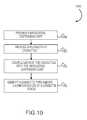
- FIG. 10illustrates another process for configuring a medication cart according to an embodiment of the invention.
- FIG. 11illustrates a method for powering a medication dispensing cart according to an embodiment of the invention.
- circuits, systems, networks, processes, and other elements in the inventionmay be shown as components in block diagram form in order not to obscure the embodiments in unnecessary detail.
- well-known circuits, processes, algorithms, structures, and techniquesmay be shown without unnecessary detail in order to avoid obscuring the embodiments.
- a processmay correspond to a method, a function, a procedure, a subroutine, a subprogram, etc. When a process corresponds to a function, its termination corresponds to a return of the function to the calling function or the main function.
- storage mediumor “machine-readable medium” includes, but is not limited to portable or fixed storage devices, optical storage devices, wireless channels and various other mediums capable of storing, containing or carrying instruction(s) and/or data.
- a code segment or machine-executable instructionsmay represent a procedure, a function, a subprogram, a program, a routine, a subroutine, a module, a software package, a class, or any combination of instructions, data structures, or program statements.
- a code segmentmay be coupled to another code segment or a hardware circuit by passing and/or receiving information, data, arguments, parameters, or memory contents. Information, arguments, parameters, data, etc. may be passed, forwarded, or transmitted via any suitable means including memory sharing, message passing, token passing, network transmission, etc.
- the process described hereinmay be implemented, at least in part, either manually or automatically.
- Manual or automatic implementationsmay be executed, or at least assisted, through the use of machines, hardware, software, firmware, middleware, microcode, hardware description languages, or any combination thereof.
- the program code or code segments to perform the necessary tasksmay be stored in a machine readable medium.
- a processor(s)may perform the necessary tasks.
- embodiments of the inventionprovide an apparatus for dispensing medication, such as a medication dispensing cart having a computer with a computer monitor and a controller.
- the medication dispensing cartmay include a power system having one or more hot swappable batteries and a power system controller.
- the medication dispensing cartmay also include a cassette system with a cassette controller and one or more individual cassettes.
- the computer controller, the power system controller, and the cassette controllermay be interfaced with the medication dispensing cart.
- the computer controllermay receive computer controller input and generate computer controller output.
- the power system controllermay receive power system input and generate power system output.
- the cassette controllermay receive cassette input and generate cassette output.
- cassettesthat are removable from the medication dispensing cart
- the cassettescould be or include drawers that are built into the medication dispensing cart.
- the cassettesare drawers coupled with the cart so that the drawers are not removable from the medication dispensing cart.
- the drawerswill be referred to herein as “cassettes” although it should be realized that use of non-removable drawers is also contemplated.
- one or more of the cassettesmay include a guide light that illuminates when the cassette or a bin of the cassette is accessed so as to visually display the location of the cassette and/or bin.
- the medication dispensing cartmay further include a stand-by button that places the computer monitor in a stand-by mode when pressed, and may include a stand-by indicator associated with the stand-by button.
- the stand-by indicatormay include a first display (e.g., a green LED) that indicates when the stand-by mode is off and a second display (e.g., a red LED) that indicates when the stand-by mode is on.
- the hot-swappable battery or batteriesmay be Li-polymer batteries.
- the power system and/or hot-swappable batteriesare configured so that a battery may be removed from the power system without affecting the power provided to the medication dispensing cart.
- the power systemmay include a battery latch mechanism to lock the hot swappable battery within the power system.
- the hot swappable battery or batteriesmay be a smart battery and the power system may include a System Management Bus (SMB) port that allows the power system to communicate with the smart battery(s).
- SMBSystem Management Bus
- the smart battery(s)may also include a gauge (e.g., gas gauge) to generate readings of the battery's remaining capacity.
- the power system controllermay be communicatively coupled with a backup battery (e.g., a third battery) that is configured to provide access to one or more bins during a power failure of the medication dispensing cart (e.g., the backup battery may provide power to locking mechanisms so that medication stored within the cart can be accessed if the hot-swappable battery(s) fail).
- the backup batterymay also detect and alarm when intrusion or otherwise unauthorized access occurs after the batteries and accessible power sources are removed.
- the cassettes systemmay comprise a combination of large cassettes, small cassettes, and the like. In one embodiment, the large cassettes comprise cassettes ranging in height between about 4 inches and about 8 inches and the small cassettes comprise cassettes ranging in height between about 2 inches and about 4 inches.
- the medication dispensing cartmay additionally include a post having a backplane that communicatively couples with one or more of the cassettes.
- the backplanemay identify the configuration of the cassette system (i.e., the arrangement and number of large and small cassettes included in the cassette system) and/or may identify the size of each of the cassettes of the cassette system (i.e., identify whether each cassette is large or small) when the cassettes are communicatively coupled with the backplane.
- the computer monitormay include a discharge element coupled to a touch screen.
- the discharge elementmay be configured to dissipate a charge generated by a user of the medication dispensing cart and/or the touch screen.
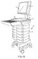
- FIGS. 1A-Cillustrate a medication dispensing cart 10 (e.g., a Mobile Medication System (MMS) cart) that includes a computer/monitor 12 (also referred to herein as touch screen 12 ), preferably an all-in-one unit having the computing device positioned within housing 14 behind the display monitor, although other configurations (e.g., separate computing devices and monitors) could be used.
- FIG. 1Aillustrates medication cart 10 without any cassettes 76 attached to a backplane 27 while FIG. 1B illustrates a plurality of cassettes 76 attached to backplane 27 .
- FIG. 1Cillustrates an enlarged view of backplane 27 of a medication cart 10 showing various features of the backplane.
- computer monitor 12comprises a touch screen display that allows a caregiver or other user to interface with the computing device and input information thereto by selecting one or more menus, inputting information, and the like via contacting monitor 12 with a finger or input device.
- Medication cart 10also includes a work surface 16 comprising a slide out keyboard 18 .
- Keyboard 18 's keypadprovides a second information input mechanism so that various information, such as entry of security access codes, patient related information, and the like may be input into the system. For example, medication information, caregiver ID, doses, patient information, time, date, and the like may be input into the computing system as treatments and/or medications are administered to the patient.
- Work surface 16is mounted atop post 24 , which is carried in turn by a rolling base 26 .
- Work surface 16can optionally include holders 37 for storing items, such as antibacterial lotions, medical supplies (gloves, and the like), writing instruments, writing pads, drinks, and the like which the caregiver or user may need when administering care with medication cart 10 .
- Medication dispensing cart 10may include other peripheral devices, such as a barcode scanner (not shown), mouse (not shown), etc.
- the keyboard 18 , barcode scanner, mouse, and/or other devicesmay be sealed to prevent the spread of infectious diseases.
- Medication cart 10 and/or work surface 16may be configurable so that additional peripheral device may be connected to medication cart 10 , such as a vital life sign monitor, scanner, etc.
- Touch screen 12may include a ground guard 13 to reduce or eliminate electrostatic discharge, which may shock a user of the cart 10 or damage sensitive equipment, such as the computer system or touch screen controller.
- Ground guard 13may discharge electrostatic charges generated as the caregiver/user performs various duties, such as administering treatment or medications to patient located within a facility.
- Ground guard 13may be positioned around an outer periphery of touch screen 12 to dissipate such charges.
- ground guard 13comprises a metal frame (e.g., metal strip and/or gasket) around the periphery of touch screen 12 .
- the metal framemay be electrically grounded to medication cart 10 (e.g., an electrically conductive chassis of medication cart 10 ) so that electric charges are dissipated as the caregiver/user touches and interacts with monitor 12 .
- the computing device positioned within housing 14 behind the touch screen 12may be enclosed in a protective case so that system is encapsulated and protected form any such discharge.
- other commonly handled componentssuch as the keyboard 18 , a mouse (not shown), a scanner (not shown), and the like may be designed to dissipate static charges as the user handles those items, such as by grounding those components with the medication cart's electrically conductive chassis.
- Post 24may be vertically adjustable so that the caregiver/user can interact comfortably with touch screen 12 , cassettes 76 , work surface 16 , and the like from a seated or standing position and/or to accommodate caregivers/users of various height.
- Post 24may be a telescoping device having an outer post member 25 that slidingly receives an inner post member 23 .
- post 24is vertically adjustable by pressing a pivot switch 29 that electronically controls a lifting mechanism.
- switch 29may be electrically coupled with a power system 28 and mechanical means (not shown), such as a screw/nut drive system that utilizes a number of small ball screws, a hydraulic lifting mechanism, and the like.
- Power system 28may control the vertical adjustment of post 24 via an actuator (not shown) connected to the mechanical means (not shown).
- actuatore.g., current sensor
- power system 28includes a sensor (e.g., current sensor) connected to the actuator that may override the vertical adjustment of post 24 based on the occurrence of one or more conditions, such as the weight of an object on work surface 16 and/or the load placed upon post 24 (e.g., the weight of the cassette system and all of its contents) exceeding a defined limit.
- the actuatorwill be tripped and post 24 will not be moveable upon actuation of switch 29 .
- the sensoror an additional sensor, may also function to disable movement of post 24 in response to sensing an obstruction that would impede vertical adjustment of the post 24 , such as an object positioned above or below work surface 16 .
- the sensed obstructionmay trip the actuator by providing a measured current that indicates the obstruction.
- post 24may be mechanically adjusted, such as by turning a hand crank or other mechanical elevating mechanism.
- outer post member 25includes the electrical backplane 27 (see FIG. 1C ).
- Backplane 27includes one or more ports 81 configured to receive and electronically couple with a cassette 76 (see FIG. 1B ).
- cassette 76may be coupled or stacked with other cassettes to form a cassette stack 30 (also referred to herein as cassette system 30 ) as shown in FIG. 1B .
- Backplane 27may also be electronically coupled with a cassette controller unit (see FIG. 6 ) that controls or interfaces with the one or more plurality of cassettes 76 of cassette stack/system 30 to provide the various access controls and/or features described herein.
- Backplane 27may house the cassette controller for monitoring the status and activities of cassettes 76 and/or receiving input for touch screen 12 .
- the cassette controllermay be a separate unit apart from the backplane 27 .
- Some of the features that may be provided by the cassette controller and/or backplane 27include: controlling the locking and unlocking of each of the bins of the individual cassettes, detecting the open/close condition of the individual bins, detecting the lock/unlock condition of the individual bins locking mechanism, automatically detecting the cassette type and configuration (e.g., detecting whether the cassette 76 is a roughly 3 inch or 6 inch cassette), automatically detecting the presence of a cassette 76 electronically coupled with (i.e., plugged into) a port 81 , controlling the guiding lights, charging of the backup battery, switching the power source between the main power source (i.e., lithium ion battery, external power source, etc.) and the backup battery, controlling an alarm mechanism, interfacing with other components of the cart 10 and/or other components of other systems (e.g., central administrator), and the like.
- the main power sourcei.e., lithium ion battery, external power source, etc.
- the cassette controller and/or backplane 27may include a storage medium (e.g., non-volatile memory, EEPROM, etc.) so that the conditions of the cart 10 and/or cassettes 76 may be monitored and recorded.
- the cassette controller and/or backplane 27may record and/or store information about the opening/closing of the bins, alarm conditions such as when unauthorized bin access occurs, power loss and recovery of the cart 10 occurs, and the like.
- This historycan be provided to a central administrator, such as a central administrator 400 shown in FIGS. 6 and 7 , so that the real time condition of the cart 10 and/or the history of the cart 10 can be monitored.
- the cassette controller and/or backplane 27may perform self-diagnostic tests to determine the status of the cassette controller and/or backplane 27 , for example, to determine when a failure of the cassette controller and/or backplane 27 occurs.
- the cassette controller and/or backplane 27may monitor the input voltage from a power source, the backup battery voltage, the cassette controller/backplane board temperature, solenoid load current, and the like. If a malfunction or other abnormality is detected, the cassette controller may report any problems to one or more systems, such as the central administrator 400 , to alert the system that repairs may be needed.
- Cart 10may include a status indicator (not shown) such as an indicator light (not shown) on backplane 27 and/or work surface 16 that notifies the user of a potential problem.
- the cassette controller and/or backplane 27may also monitor the status of cart 10 and/or cassettes 76 .
- the cassette controller and/or backplane 27may be electronically coupled with one or more sensors (not shown) to determine if the lock mechanism is locked or unlocked, if the door is open or closed, etc.
- the sensorsrespond to requests/communications received from the cassette controller and/or backplane 27 .
- the sensorsprovide information without receiving requests from the cassette controller, such as when the sensors sense a bin is opened and/or a locking mechanism is disengaged, etc.
- the cassette controller and/or backplane 27may receive an input from a caregiver or other user to unlock one of the cassettes 76 that includes a patient's medications.
- the cassette controller and/or backplane 27may instruct a locking mechanism, such as a solenoid, to unlock the requested cassette 76 and/or bin.
- a locking mechanismsuch as a solenoid
- the cassette controller and/or backplane 27may be coupled with a sensor (e.g., photointerrupter sensor, etc.) and feedback loop and the status of the locking mechanism may be determined, such as if the solenoid has been disengaged.
- a sensormay be used to determine if the bin door is opened or closed.
- the actual status of the locking mechanism and/or binmay be determined to ensure that the actual status corresponds with what the cart's control system (and/or central administrator) believes the status to be (e.g., verifying that the bin is actually closed).
- the status of the locking mechanism and/or binmay be checked intermittently (e.g., at specified or irregular time intervals) or continuously. If the status of the bin is other than that expected by the cart's control system (e.g., the locking mechanism is unlocked when the control system indicates the locking mechanism as being locked), the cart's control system may be updated, the discrepancy recorded, an alarm triggered, and/or a control system (e.g., central administrator) alerted to notify one or more individuals or systems about the discrepancy. Likewise, the history of any discrepancies can be stored so that the individual carts and/or the entire cart system can be monitored and problems addressed.
- the cassette controller and/or backplane 27may automatically detect the type of cassette that is plugged in. For example, the cassette controller and/or backplane 27 may determine if the cassette 76 is a large or small cassette (e.g., roughly 3 inch cassette, 6 inch cassette, or another size) and may automatically configure the port to interface with the cassette based on this determination, such as be installing or using the appropriate device controls/drivers, using or modifying appropriate software, and the like. In this manner, various combinations of cassette types may be used with the medication cart 10 depending on a patient's needs and/or depending on other situations. In addition, the cassette controller and/or backplane 27 may further monitor the charge of the backup battery, control the charging of the backup battery, control the guide lights, and/or control the cassette override inputs as described below.
- the cassette controller and/or backplane 27may further monitor the charge of the backup battery, control the charging of the backup battery, control the guide lights, and/or control the cassette override inputs as described below.
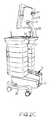
- FIGS. 2A-Cillustrated are various rear views of the present medication cart 10 showing touch screen 12 , work surface 16 , post 24 , and power system 28 , which is supported by rolling base 26 .
- Work surface 16can further include hidden USB port 80 for use if additional electronic devices need to be employed, such as scanners, vital sign monitors, mouse devices, and the like.
- Touch screen 12may be attached to post 24 or the rear surface of work surface 16 via mount 35 to maximize the usable area of work surface 16 (i.e., provide the maximum work space to the caregiver/user).
- Touch screen 12may be mounted using a tiltable bracket 34 so that the viewing angle of touch screen 12 can be adjusted to accommodate the caregiver/user.
- a clear hard coveringmay be applied over the monitor portion of computer/monitor 12 in order to make computer/monitor less susceptible to scratches and impact.
- the coveringmay be about an 1 ⁇ 8 th inch thick and made of acrylic polymeric plastic or other suitable plastic polymer.
- Work surface 16may include a standby button 39 (e.g., a HIPAA (Health Insurance Portability and Accountability Act) button) that may be used to quickly place touch screen 12 into a standby or disabled mode so as to protect sensitive information that may be displayed on touch screen 12 .
- touch screen 12may display patient information, which may include sensitive information such as medical history, prescribed medications, and/or other personal information. If the medication cart 10 is in a public area, such as when the cart is being moved between patient rooms, standby button 39 may be pressed to override the input signals from the computer system and black out touch screen 12 .
- a standby button 39e.g., a HIPAA (Health Insurance Portability and Accountability Act) button
- Standby button 39may include a standby indicator that visually displays the standby status of the standby button and touch screen 12 , such as to display whether the monitor is in standby or disabled mode.
- the standby indicatormay be color coordinated to display the status of the standby button and/or touch screen 12 .
- standby button 39may be green when touch screen 12 is not in standby or disabled mode and red when touch screen 12 is in standby or disabled mode.
- touch screen 12When touch screen 12 is in standby or disabled mode, touch screen 12 may not display anything (e.g., screen is black) so that the monitor and/or computer system appears to be off. In other embodiments, the standby or disabled mode may generate a screen saver image or series of images/videos that are displayed. Providing a standby indicator allows a caregiver or other user to quickly determine whether the screen is blank or in screen save mode due to touch screen 12 being in standby or disabled mode or being powered off. In this manner, accidental restarts may be avoided that may otherwise occur due to a caregiver/user mistakenly powering off cart 10 's computer system's when touch screen 12 does not respond to inputs from a mouse, keyboard, or touch screen input.
- the standby or disabled modemay generate a screen saver image or series of images/videos that are displayed.
- Avoiding accidental restartsmay avoid deletion of material entered into, but not yet stored in, the computer system and/or may avoid other problems associated with not realizing that touch screen 12 is in standby or disabled mode (e.g., interruption of data continuity, mistaken belief that cart 10 is malfunctioning, etc).
- cart 10 ′s computer systemmay automatically switch touch screen 12 to standby or disabled mode after a predefined time has elapsed without input from the caregiver/user to conserve battery power and/or protect sensitive information.
- the standby button's 39 indicatormay display when the monitor 12 is in such standby or disabled mode.
- Power system 28may include a battery receptacle 50 having one or more slots 52 (element 302 of FIGS. 3A-D ) that are configured to receive a battery. Power system 28 may be placed near the bottom of medication cart 10 to lower the cart 10 's center of gravity and provide stability to the cart. Additional aspects of power system 28 are illustrated in FIGS. 3-4 .
- power system 28which is connected through post 24 to touch screen 12 , includes a power system controller (not shown, but see FIG. 6 ) and a plurality of battery slots 302 that are configured to receive a battery 402 (see FIG. 4 ).
- Power system 28is coupled with and supported by rolling base 26 .
- Power system 28may be detachably coupled with an external power supply, such as through a detachable power cord 322 .
- Power system 28may include a universal AC power input so that the power cord 322 may be swapped to match the AC plug, thereby allowing the medication cart to be used in virtually any country.
- Power system 28may power medication cart 10 via the external power supply (i.e., without a battery) and/or may charge batteries 402 when connected with the external power supply. Power system 28 may further include a power supply bracket 326 to secure the external power supply (e.g., power cord 322 ) to the power system 28 .
- the external power supplye.g., power cord 322
- Battery slots 302may each slidably receive a battery 402 . Disposed toward a bottom surface of battery slots 302 may be one or more ports, 306 and 308 , that electrically couple or plug into corresponding connectors on the battery (see FIG. 4 ). Ports, 306 and 308 , may each be a five-pin electrical connector configured to support and/or operate with hot swappable smart Li-polymer battery packs. In one embodiment, port 306 may be a power connection port that draws power from the battery 402 during operation of medication cart 10 and/or provides power to the battery 402 when an external power supply is plugged into the power system 28 . In this manner, power system 28 may recharge battery(s) 402 plugged into power system 28 .
- port 308may be a System Management Bus (SMB) port.
- SMBSystem Management Bus
- the SMB port 308may allow the power system controller to communicate with the battery during use and/or charging. For example, through SMB port 308 and/or power connection port 306 , the power system controller can communicate with the battery to monitor and track usage and/or charging of the battery and thereby maximize the lifespan and/or potential of the battery.
- SMBSystem Management Bus
- the power system controllercan receive information from the battery such as an optimal charge current and/or charge voltage and vary either or both the charge current or voltage during a charge cycle.
- the power system controllercan receive information from the battery about an optimal discharge current and/or discharge voltage during operation of the cart 10 and adjust the cart's power settings and battery usage accordingly. As the battery is charged and/or ages during use, the charge and/or usage requirements of the battery may change.
- This informationmay be provided to the power system controller from the battery so that the charge setting (i.e., current and/or voltage) and/or usage settings (i.e., charge and/or voltage supplied from each battery) may be adjusted in real time, and thereby optimize the charge and/or usage of the battery. In this manner, the charge and/or operation of each battery may be monitored by the power system controller.
- the power system controller and/or batterycan monitor and/or control include: The battery cell voltages, battery pack voltages, charge current, discharge current, charging temperature, discharging temperature, idle mode temperature, and the like.
- the communication between the battery and the power system controllerallows the medication cart to accommodate and adjust to different batteries so that battery usage and/or charging is optimized regardless of the batteries used. Further, this information may be monitored and provided to a central administrator 400 so that battery performance and/or cart performance may be monitored.
- the power control systemmay disconnect the battery from use and/or charging and alert one or more other systems, such as a central administrator 400 and/or the cart's monitor/computer controller.
- the batterymay communicate to the power system controller (via SMB port 308 ) that the current and/or voltage of a charge exceeds a safe amount (or is excessive for optimal charging).
- the power system controllercan adjust the current and/or voltage provided or disconnect the battery from charging so as to avoid malfunctioning or failure of the battery.
- the power system controller, and/or the battery itselfcan reset the battery after the stress condition is cleared.
- the power control systemmay avoid catastrophic failure of the battery and, thus, failure of the medication cart 10 .
- the power system controlleris unresponsive to requests from the battery (e.g., a request to adjust the current and/or voltage)
- the batteryitself may disconnect from the power system to avoid malfunctioning or failure.
- the power system controller and batterymay function in a similar manner during operation so as to adjust the power requirements demanded of the battery and/or disconnect the battery from power system 28 .
- the power system controllermay record historical data about each of the batteries used. This data may be used for debugging or monitoring purposes, such as to determine when a battery needs replacement or to determine an optimal arrangement for the batteries within a fleet of medication carts. This historical data may be provided and/or stored by the central administrator.
- the historical/lifetime data for each batterymay include: maximum/minimum temperature, maximum/minimum cell voltage, maximum/minimum pack voltage, maximum charge current, maximum discharge current, maximum charge power, maximum discharge power, life maximum average discharge current, life maximum average discharge power, average temperature, etc.
- Each batterymay include a unique serial number that is read by the power system controller and/or provided by the battery so that the data (i.e., real time and/or historical) for each battery may be recorded and monitored regardless of whether the battery is used with the same medication cart 10 or different medication carts.
- the power system controlleris able to recognize each battery that is used with the medication cart and provide battery data to central administrator 400 that corresponds with the specific battery used.
- the central administratormay keep a database of each battery used in the system.
- the databasemay include an identifier for each cart the batteries were used with, the performance of each battery over their lifetime, and/or the real time status of each battery.
- Power system 28may include hot swappable dual battery slots 302 , or put another way, the battery slots 302 may be hot swappable. Hot swappable battery slots 302 may allow for a battery to be removed from power system 28 without interrupting the power provided to the medication cart 10 (e.g., without loss of power, or data, to computer/monitor 12 ).
- FIG. 3Dillustrates power system 28 having a single battery 402 inserted within one of two battery slots 302 . The single battery 402 is able to provide sufficient power to operate medication cart 10 . Medication cart 10 may automatically adjust to draw power from one of the batteries as the other battery is detached and removed from one of the battery slots 302 .
- Individual batteries 402may be removed from power system 28 to charge the battery, replace the battery, inspect the battery, perform maintenance, and the like. Further, because an individual battery 402 is capable of powering medication cart 10 , the medication cart is not susceptible to failure due to the failure of a single battery. In other words, each battery 402 may act as a backup power supply in case of failure of the other battery. Further, the hot swappable feature of the power system 28 provides for continuous operability of the medication cart 10 without having to plug in the medication cart to recharge the batteries. For example, the medication cart could essentially run indefinitely without plugging the medication into an external power source, provided the batteries are regularly removed and/or recharged.
- the power system controllermay communicate status information about the battery to power system 28 , which information may be visually displayed via one or more displays 318 (e.g., LED indicators) of power system 28 .
- FIG. 3Aillustrates display 318 comprising the following indicators: an external power supply indicator AC that shows when an external power supply is plugged into power system 28 , a fault indicator F that displays when a battery is malfunctioning or otherwise has a problem, an indicator for one or more battery slots 302 that shows when a battery is connected with each slot (e.g., indicators 1 and 2 ), and a charge level indicator C that shows the charge level of a selected battery or the charge level of the power system.
- an external power supply indicator ACthat shows when an external power supply is plugged into power system 28
- a fault indicator Fthat displays when a battery is malfunctioning or otherwise has a problem
- an indicator for one or more battery slots 302that shows when a battery is connected with each slot (e.g., indicators 1 and 2 )
- a charge level indicator Cthat shows the
- the charge level of each batterymay be displayed via indicator C by selecting either indicator 1 or 2 , otherwise indicator C may display the overall power level of power system 28 . In this manner, the caregiver/medication cart user may quickly determine the real time status of each battery being used for power system 28 or determine the overall power level for power system 28 .
- Each battery slot 302may additionally include a receiving mechanism that facilitates in receiving battery 402 into the slot (see FIG. 3C ).
- power system 28may include a first slide member 310 A and a second slide member 310 B that correspond with slide guides (see FIG. 4 ) on the battery to facilitate in slidably receiving battery 402 within battery slot 302 .
- the first slide member 310 A and second slide member 310 Bmay be sized and/or shaped differently so as to properly orient battery 402 upon insertion into the slot 302 .
- the slide membersmay be shaped and/or sized so that battery 402 is only receivable in one orientation (i.e., the battery only fits into the slot in one direction).
- Each slot 302may further include a latching mechanism 314 that detachably couples the battery in the slot 302 .
- the latching mechanism 314may be a recessed portion in the slot that is configured to receive a latch or hook (see FIG. 4 ) of battery 402 .
- Other forms of detachably coupling the batteryare also contemplated herein, which may include detents, grooves and corresponding members or gaskets, coupling cam mechanisms, locks, pins, screws, and the like.
- the latching mechanismmay allow for quick release of the battery from within the slot so that a user may quickly exchange batteries in one or more of the slots with a single hand. For example, the user may grasp the battery with one hand and engage a removal member with a finger or thumb to unlock the battery within the slot.
- Power system 28may further include a lid 330 (see FIG. 3B ) that is pivotally coupled with power system 28 to enclose and/or secure the batteries within slots 302 .
- FIG. 3Billustrates the power system 28 including two batteries 402 coupled within battery slots 302 with the lid 330 enclosing the batteries within the power system.
- the figurefurther shows displays 318 indicating a full charge level C for power system 28 and/or for one of the selected batteries.
- Battery 402may be a hot swappable smart Li-polymer battery pack (Lithium ion battery).
- the Li-polymer battery packmay provide a longer battery life, higher energy content per weight, and substantially no periodic maintenance charge when compared to similar lead-acid batteries.
- each battery packprovides a voltage range of 13.0 to 16.4 volts, and preferably in the range of 14.8 volts.
- battery 402can be charged in combination with cart 10 or independently of cart 10 .
- Work surface 16may include a plug rest 33 (shown in FIG. 2 ) for conveniently storing the power cord 322 when the cart 10 is being moved, operated solely on battery power, or not in the vicinity of a power source.
- Each individual battery 402may be designed to power cart 10 through at least one eight hour shift before requiring recharging, and preferably through at least one 10 hour shift. In other words, each battery 402 may power medication cart 10 for at least a single 8-10 hour shift. This operational time of a single battery may allow the other battery to be removed for recharging, inspecting, maintenance, and the like. When two batteries are used the operational time can be extended to last beyond two shifts, or approximately 18-20 hours.
- Battery 402may include one or more connectors, 430 and 434 , that allow the battery to communicate information to an external source, such as the power system controller and/or an external battery charger.
- Connector 430may be a power connector that corresponds with port 306 in power system 28 to provide power to power system 28 and/or receive power from an external source.
- connector 434may be a SMB connector that corresponds with SMB port 308 in power system 28 .
- the battery 402may additionally include an internal interface board (not shown) that monitors the characteristics described above (e.g., charge, voltage current, temperature, etc) and communicates this information to the external source. External communication from the interface board may be provided via SMB connector 434 and/or power connector 430 .
- the interface boardmay initially provide, via SMB connector 434 , information to an external battery charger or the power system controller regarding an optimal charge current and/or voltage, which current and/or voltage the battery charger and/or power system controller may provide.
- the optimal charge current and/or voltagemay change, which may be detected by the interface board and relayed to the battery charger and/or power system controller.
- the interface boardmay itself monitor the current and/or voltage provided by battery 402 during operation of the cart 10 and relay this information to the power system controller.
- the interface boardmay also monitor the current and/or voltage provided from or received by the power connector 430 and provide this information to an external source.
- battery 402may include several layers of protection to protect against malfunction and/or catastrophic failure, which may damage the medication cart 10 and/or cart's control system.
- the interface boardmay detect when stress levels (e.g., temperature, current, voltage, etc.) exceed predefined parameters. In such instances, the board may relay this information, via SMB connector 434 , to an external source (e.g., the power system controller and/or battery charger) so that one or more adjustments may be made and/or the battery may disconnect itself from the external source. Further, battery 402 may reset itself once the stress condition is cleared or otherwise taken care of.
- Battery 402may utilize gas gauging technology, such as Texas Instrument Impedance Track® (TI bq20z90 IC), to generate accurate readings of the battery's remaining capacity.
- the batterymay support the Smart Battery Specification (SBS) v1.1 (i.e., may be SBS v1.1 compliant) or other standards.
- Battery 402may include one or more displays 408 that indicate the status of the battery, such as the charge level. To show the status (e.g., charge level), battery 402 may include a battery status button 406 , which, when pressed, provides an status indication via display 408 , such as illuminating one or more LEDs.
- the battery's case 404may be constructed of a flame retardant plastic.
- the casemay be ultrasonically welded together and/or comprise one or more screws to fasten the case together.
- the batterymay also comprise a unique serial identifier that identifies the individual battery.
- the information associated with the unique serial identifiermay be stored internally in one or more storage mediums. This unique identifier may also be provided to an external source via SMB connecter when the battery is coupled with the external source, such as a battery charger or power system 28 .
- the battery's case 404may include slide guides 420 A & B disposed on opposite sides of the case that correspond with slide members 310 A & B, respectively.
- the slide guides 420 A & Bmay be shaped and/or sized so that each slide guide corresponds only with one of slide members 310 A & B to ensure that the battery is properly oriented when it is inserted into slot 302 .
- the batterymay further include a handle 422 so that the battery 402 may be easily transported and may additionally include a locking mechanism (see FIG. 4A ), such as latch 414 that is configured to lock into recess portion 314 of power system 28 .
- latch 414may retract into handle 422 until the battery is fully positioned within slot 302 .
- latch 414may lock into recess 314 , such as by being outwardly biased via a spring (not shown) disposed within handle 422 .
- Latch 414may be coupled with a removal member, such as knob 416 , that retracts latch 414 within handle 422 when engaged (e.g., when slid along handle 422 ). In this manner a user may easily remove the battery by grasping handle 422 and engaging knob 416 , which retracts latch 414 within the handle, thereby unlocking the battery 402 and allowing the battery to be removed from slot 302 .
- battery 402may include other locking mechanisms, which may include detents, pins, compliant members, locking cams, screws, etc.
- Medication cart 10may also include a backup battery (not shown) that provides some cart functionality in case of a complete power failure of battery(s) 402 .
- the backup batterymay be a lead-acid battery or a Li-polymer battery.
- the backup batterymay allow medication cart 10 to remain operational for a short period of time so that one or more operations may be completed, such as administering medications, providing treatment, locking and securing narcotics within cart 10 , entering patient or treatment information into cart 10 's computer system, and the like.
- the backup batterymay be electrically coupled with the cassette controller and/or backplane 27 to provide complete access to all the cassettes 76 in case of a complete power failure.
- Complete access to all the cassettes 76 in the event of a complete power failuremay be provided upon providing one or more inputs, such as by engaging an administrator key and one other key (e.g., nurse key).
- the backup batterymay override the system control locks and provide access to any or all the cassettes 76 .
- any or all cassettes 76may be accessed even when the cart's control system is non-operational, thereby allowing access to medication and/or personal possessions that may be kept in the cassette (i.e., in one of the cassette's bins).
- the power system controllermay control the charging of the backup battery to ensure that the backup battery is charged in case of a complete power failure.
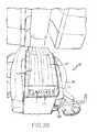
- FIG. 5Aillustrates an exploded, detailed view of the cassette system 30 .
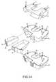
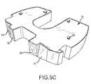
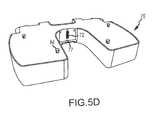
- FIGS. 5B-Dillustrate an individual cassette 76 of the cassette system 30 .
- Cassette system 30is preferably modularized, and includes a cassette manager 70 .
- the cassette system 30is generally connected to work surface 16 and wired to touch screen 12 via backplane 27 . More particularly, the top of cassette manager 70 may be fastened to the under surface of work surface 16 .
- cassette manager 70includes fasteners 74 (e.g., bolts) along its top surface that allow cassette manager 70 to be bolted to the under surface of work surface 16 .
- cassette manager 70includes a first key override lock 71 and a second key override lock 73 that may be operable with the battery backup (not shown) as described above to provide access to any or all the cassettes and/or bins in case of a complete power failure or for any other reason.
- cassettes 76may vary in size. In one embodiment, the cassettes may range in size between about 4 and 8 inches in height (and preferably about 6 inches) and/or about 2 and 4 inches in height (and preferably about 3 inches), although a variety of sizes are contemplated herein.
- Cassette system 30may include any combination of sized cassettes 76 . In one embodiment, if cassette system 30 includes all large sized cassettes (e.g., 4-8 inch cassettes), up to 6 cassettes may be included in cassette system 30 .
- cassette system 30may include all small sized cassettes (e.g., 2-4 inch cassettes), up to 12 cassettes may be included in cassette system 30 .
- cassette system 30may include any combination of large and small sized cassettes so that more or less cassettes may be added (i.e., 8 cassettes, 10 cassettes, etc.).
- backplane 27may automatically configure itself to operate with the various sized cassettes and cassette configurations.
- FIGS. 5B and 5Dillustrate cassette 76 's connector 72 that couples with port 81 on the backplane 27 .
- Connector 72may communicatively couple the cassette system controller or backplane 27 (or cart 10 's computer system) with cassette 76 so that the various cassette functionalities described herein may be provided, such as: locking and unlocking cassette bins, illuminating the guide lights, assigning cassette bins as patient specific or utility specific bins, sensing the lock/unlock status of bins, sensing whether the bins are open or closed, and the like.
- Cassette 76may further include a post 77 that corresponds with an aperture (see FIG. 1C , element 75 ) on backplane 27 .
- Post 77may facilitate in properly aligning cassette 76 with backplane 27 to ensure that connector 72 easily plugs into the port 81 .
- the cassette controller unitmay sense the size of the cassette (i.e., sense whether the cassette is roughly 6 inch or roughly 3 inch cassette as described herein), and may further sense the cassette 76 configuration of cassette system 30 .
- Backplane 27may also sense additional information associated with cassette 76 , such as whether one or both of the bins are designated as patient specific or utility bins.
- Patient specific binsmay be bins that have been assigned for use in storing personal belongings of the patient and/or medication specifically prescribed for the patient and/or specifically for use for the patient.
- Utility binsmay be bins that have been assigned to carry common items used by caregivers or other users as they assist the patients (e.g., bandages, gauze pads, syringes, over the counter medications, etc). Utility bins may automatically open upon receiving an authentication of the caregiver or user or may not require any authentication to open.
- the cassettes and/or binsmay be re-assignable by the nurse and/or central administrator.
- cart 10may include all utility bins and/or cassettes, all patient specific bins and/or cassettes, or any combination thereof.
- Each cassette 76(and cassette manager 70 ) may include a latching mechanism.
- the latching mechanismmay include a plurality of dovetail-shaped cutout portions 80 that are dimensioned to receive dovetail-shaped projections 84 of an adjacent cassette 76 .
- Dovetail shape projections 84may be positioned on the top surface of the cassette 76 , while the dovetail shaped cutouts are positioned on the bottom surface of the cassette 76 .
- cassette manager 70may include a plurality of dovetail-shaped cutout portions 80 on its bottom surface so that cassette manager 70 may couple with a cassette 76 positioned immediately below cassette manager 70 . In operation, dovetail projections 84 may simply slide into dovetail cutouts 80 .
- cassette manager 70 and cassette 76are generally U-shaped to facilitate engagement with post 24 by fitting around post 24 .
- the U-Shaped cut out portion of cassette 76 and/or cassette manager 70may include a flat portion that includes connector 72 and post 77 .
- the flat portionmay correspond with the flat backplane 27 .
- Each cassette 76typically has at least two bins 94 that are independently lockable through electronic locks 100 and that have corresponding sensors 110 . Sensors 110 determine if a bin 94 is open or closed and or may determine if the electronic lock 100 is engaged or disengaged as described above.
- the cassette controller and/or backplane 27may continually monitor the status of the bins 94 so that upon unauthorized access, an alarm is sounded and an email is sent to a system administrator (e.g., central administrator).
- a system administratore.g., central administrator
- all or a majority of locks 100are software controlled, while in other embodiments, locks 100 may use keys or a combination of keys and software lock.
- lock 100could include a software controlled solenoid actuator connected to a lever.
- Cart 10 's computer systeme.g., touch screen 12
- Cart 10 's computer systemcan be programmed to lock and secure every bin 94 unless and until unlocked by an authorized user having an appropriate level of authorization who inputs a correct security code via keyboard 18 , touch screen 12 , a scanner (e.g., bar code scanner), and the like.
- the cassette controllermay have a time out feature so that all cassettes and/or bins are locked if an input is not received from a caregiver or other user within a defined time period, for example, if a bin 94 is not opened within a predefined time after being unlocked.
- cart 10 's computer systemmay provide access to a patients bin 94 upon a positive verification of the patient, such as by scanning a patient's wristband. Access to the bin 94 may also require two positive identifications of the patient, such as by scanning the patients' wristband and receiving a confirmation of a secondary identifier from the caregiver or user that the patient identified by the system is in fact the patient being treated.
- the confirmationi.e., secondary identifier
- the confirmationmay include receiving an input from the caregiver via the touch screen, keyboard, mouse, and the like acknowledging that the patient's characteristics displayed on touch screen 12 (e.g., patient's sex, height, weight, name, age, hair color, etc.) match the actual patient receiving care.
- guide lights 90 for the patient's bin 94may be illuminated to visually guide the caregiver to where the patient's bin is located.
- Access to a bin 94 containing narcoticsmay require two pass codes; otherwise one pass code may unlock a bin 94 .
- Each usere.g., a nurse
- cart 10 's computer systemmay record the time and date of the access by that user. This access information (e.g., date, time, user, etc.) may be reported to the central administrator 400 (see FIG. 6 ) so that bin access may be monitored.
- Central administrator 400may network a plurality of medication carts 10 so that a nurse's identifier and/or password is capable of unlocking and operating any medication cart 10 networked to the central administrator 400 .
- Cart 10may be optionally provided with a plug-in scanner for reading medication containers to facilitate in accurately loading cassettes 76 /bins 94 and/or providing cart 10 's computer system (or central administrator 400 ) with information about the medications being loaded into each bin 94 .
- the system administratore.g., central administrator 400
- each cassette 76may include one or more guiding lights 90 that illuminate (e.g., the exemplary illumination region shown in cross hatch in FIG. 5A ) a portion or the entire face of bin 94 to visually display a bin 94 having a needed medical supply and/or corresponding to an identified patient.
- the guide light 90may illuminate the inner third of the face of the bin 94 (e.g., illuminate a third of the bin closest to the post) so that the nurse may quickly identify which bin is the patient's bin that has been unlocked.
- more than one bin 94may be assigned to a patient so that upon entry of an authorization code and selection of that patient, the face of multiple bins illuminate.
- guide lights 90may illuminate a specific one of the patient's bins 94 based on a selection of a drug to administer to the patient that the system recognizes is kept in the specific bin. In this manner, the system may differentiate between multiple bins 94 assigned to a specific patient. Likewise, the system may illuminate guide lights 90 of a utility bin when general medications are required.
- the operational systemincludes a computer controller and interface logic 200 that receives computer controller input and generates computer controller output.
- computer controller 200processes user input, such as the identity of user, the biometric information of user, pass codes entered by user, etc.
- cassette, bin, power, and/or batter related functionssuch as: locking/unlocking bins, assigning cassettes and/or bins as patient-specific or utility specific, monitoring the status of cassettes and/or bins, identifying or determining the cassette stack configurations and/or cassette sizes, facilitating in loading and administration of medications, monitoring and/or adjusting battery power (e.g., current and/or voltage), monitoring battery status, monitoring and/or adjusting cart 10 's power usage, decoupling unstable batteries, and/or any of the other functions described herein.
- Computer controller 200may perform these various functions with the assistance of the various other controllers described herein and specifically shown and described in FIG. 6 , such as the power system controller, the cassette controller, and the like.
- cart 10's computer system comprises all these controllers or a single controller that performs the controller functions described herein.
- the user information and/or access informationmay be reported to the central administrator 400 so that cassette/bin access and/or user access may be monitored by the central administrator.
- central administrator 400may tie all the medication carts 10 in the system together and may tie all users in the system together so that a nurse's identifier and/or password is capable of unlocking and operating any of the medication carts 10 tied to the central administrator 400 , thereby eliminating the need for passwords specific to each cart.
- central administrator 400may render the user's identifier and password inoperable, thereby eliminating the possibility that the user may use their password to gain access to a cart.
- Computer controller 200may provide output to cassette system 30 via backplane 27 and/or cassette controller 500 relating to the designation of cassettes 76 and/or bins 94 included in the cassette system 30 (e.g., outputs patient cassette and/or bin assignments, patient specific bin assignments, utility bin assignments, etc.).
- the designation of cassettes 76 and/or patient specific bins 94may be tied with the central administrator 400 , such as a hospitals Admission Discharge Transfer (ADT) system so that cassettes 76 and/or bins 94 are automatically assigned by the ADT system upon admittance into the hospital and assignment to a bed.
- ADThospitals Admission Discharge Transfer
- the ADT systemmay assign multiple cassettes or bins and/or determine the size of the cassettes 76 needed (e.g., roughly 6 inch or roughly 3 inch cassettes). Further, the cassette and/or bin assignments may be automatically transferred by the ADT system as the patients is transferred between rooms and/or floors within the hospital. In some embodiments, the cassette/bin assignments are stored in a memory medium of the cassette (or centrally on a network) so that the assignment information is automatically uploaded to the cart 10 's computer system (e.g., computer controller 200 ) when the cassette is plugged into a port 81 of backplane 27 .
- the cart 10 's computer systeme.g., computer controller 200
- the ADT systemprovides information about patients that have been assigned to the ward in which the nurse is working and one or more patients may be assigned to the nurse, such as by the nurse assigning the patients to themselves.
- the systemmay provide the nurse with a listing of the patients in the ward. The nurse may select a patient and then select a cassette 76 and/or bin 94 from a display provided on touch screen 12 or may select an auto-assignment function in which the cart automatically assigns one or more cassettes 76 and/or bins 94 .
- the patient's information(e.g., medical history, medication, room number, etc.) may be automatically provided to the cart 10 and associated with the assigned cassettes 76 and/or bins 94 so as to eliminate the need for the nurse to manually input any information.
- Cassette 76 and/or bin 94 selections/assignmentsmay be provided to the central administrator 400 , so that the cassette/bin assignment is monitored and/or recorded.
- Information that is communicated to the cart and/or from the cartmay be queued so that information that is not immediately deliverable may be subsequently delivered.
- the patient informationsuch as patient assignments, medical history, medications, and the like is provided to a specific medication cart 10 (i.e., computer/monitor controller) from central administrator 400 , but is unable to be delivered due to power failure of the cart and/or network
- the informationmay be queued so that upon returning online (either the cart or network or both), the information is resent to the medication cart 10 .
- each medication cart 10may be fully operational despite the central administrator 400 and/or network (i.e., wireless network 300 ) going down.
- the cart 10may have a redundant system in place so that when the cart becomes disconnected from the network, the cart is still fully operational, thereby allowing cart 10 to interact and record events, such as the battery status, cassette and/or bin status, access status, patient cassette and/or bin association, etc.
- the central administrator 400 and/or networke.g., wireless network 300
- medication cart 10may communicate the information recorded while the central administrator and/or network was down. In this manner, the transition between cart functionality when the network and/or central administrator 400 is online and offline may be seamless or near seamless.
- the operating systeme.g., cart 10 's computer system
- cart 10may be equipped with a wireless network connection 300 , preferably through SMTP (simple mail transfer protocol) so that the cart 10 , or a user of that cart, can communicate with a central administrator 400 about conditions of the cart, such as a low battery, user access, and the like.
- Cart 10may also communicate with administrator 400 without the active assistance of the user. Accordingly, the status and whereabouts of cart 10 can be constantly and effectively monitored through wireless communication along with the status of the batteries, user access history, and the like as described above.
- the cassette system 30may also include cassette controller and interface logic 500 , which may be housed in or otherwise communicatively coupled with backplane 27 .
- This cassette controller 500receives input from the computer controller 200 about the cassettes 76 and/or bins 94 and their designations and also automatically determines the size of the attached cassettes 76 and the configuration of the cassette system 30 , which information may be relayed to computer controller 200 .
- cassette controller 500can lock and unlock bins 94 based upon receiving an authorized input and/or receiving an override input.
- the cassette controller 500may log bin access and status, including when they are opened and by whom. Accordingly, the cassette system 30 has the ability to monitor itself.
- power system 28also includes power system controller and interface logic 600 , which monitors the condition and/or charging of battery(s) 402 .
- the power system controller 600may also control the raising and lowering of post 24 .
- the power system controller 600may communicate with central administrator 400 to provide status information about the battery and/or other conditions of cart 10 .
- Cart 10 's computer systeme.g., touch screen 12
- may also automatically reporte.g., via email, SMS, MMS, and the like) an attempt to break into cart 10 , a log of the charging system, a log of the times and the identities of users who have accessed each cassette. Other information can also be reported.
- FIG. 7Illustrated in FIG. 7 is a simplified system 700 of a central administrator 400 that may centrally manage a plurality of medication carts 10 .
- Central administrator 400may be tied to a hospitals Admission Discharge Transfer (ADT) system, Pharmacy Information System (PIS), administration system, and/or Automated Dispensing Machine (ADM). Further, the central administrator may be a sub-component of the ADT/ADM system or may be a separate control system.
- Each of the medication carts 10may include a power system controller, cassette controller, and computer/monitor controller as described above, which monitors information about various aspects of the cart (e.g., user access, cassette/bin access, battery status, patient information, unauthorized access, etc.).
- This informationmay be provided to the central administrator 400 so that the central administrator can centrally manage the real time status and historical status of each cart 10 .
- the central administrator 400is capable of monitoring and recording every event that occurs at the medication cart 10 , such as the user access history (i.e., based on user identifier and/or password), battery history, cart location history (i.e., floor assignment), patient history, etc. Further, the central administrator may differentiate between events, such as differentiate between whether a bin 94 access occurs due to a nurse authentication (i.e., input user identifier and password) or a patient authentication (i.e., patient wristband scan and secondary identifier).
- a nurse authenticationi.e., input user identifier and password
- a patient authenticationi.e., patient wristband scan and secondary identifier
- the central administrator 400may centrally manage the batteries used in the medication carts 10 and monitor the users that operate the carts.
- the informationmay be provided via one or more networks, such as wireless network 300 or a wired network.
- the central administrator 400may directly interact with the medication carts 10 (shown by the solid lines directly connecting central administrator 400 and carts 10 ) and/or may indirectly interact with the carts by interacting with a sub-controller system 710 , which in turn directly interacts with the carts 10 .
- the medication carts 10may directly interact with a sub-controller system 710 that is located on the floor or ward where the cart resides.
- the sub-controller system 710may be controlled by the central administrator 400 , such as the hospital administration system.
- Information exchanged between the cart 10 and the central administrator 400may be routed through the sub-controller system 710 so that additional information (e.g., floor specific information) may be added and/or unnecessary information removed. Further, the central administrator 400 may quickly transfer or exchange information between carts 10 , such as transferring patient information when a patient is transferred between floors.
- additional informatione.g., floor specific information
- the central administrator 400may quickly transfer or exchange information between carts 10 , such as transferring patient information when a patient is transferred between floors.
- the information provided to the central administrator 400may be stored in a database 702 , which may be remote from central administrator 400 or included therewith.
- the informationmay be stored for a predetermined amount of time (e.g., store information for a year).
- central administrator 400may be coupled with or include a monitoring and reporting system 704 that monitors real time and historical data about each cart 10 including: battery status and/or history (charge rate, discharge state, shutdown events), user access (logon, logoff), access events, bin access/activity (unlock, lock, open, close), etc.
- the monitoring and reporting system 704may generate one or more email notifications/or paper reports (e.g., work orders) based on real time or historical events that occur (or have occurred), such as when a dead battery is detected, low battery is detected, an unauthorized cassette/bin access occurs, a patient medication schedule is missed, excessive and repeated bin access is observed, etc.
- the monitoring and reporting system 704may further generate one or more reports based on system/cart audits performed.
- the auditing and/or monitoring parameters for batteries, users, access events, etc.may be predefined in the system so that reports are automatically generated when the parameters are exceeded.
- central administrator 400may be tied to the hospital's ADT, PIS, and/or ADM systems, information input into one of those systems may be immediately available and provided to the medication chart. For example, as medications are provided or updated by a pharmacist, the additions or modifications can immediately or nearly immediately be displayed, via the PIS, on touch screen 12 of medication cart 10 . Likewise, dosage amounts and/or frequency input into touch screen 12 of cart 10 may be immediately available to the supervising physician or doctor. Medication cart 10 may be operable with pre-existing hospital systems so that no additional hardware and/or software is needed to integrate medication cart 10 into the system. Thus, carts 10 may be essentially plugged into and used with currently operating administration systems.
- FIG. 8Illustrated in FIG. 8 is a process flow diagram for operational use and features of the medication cart system.
- one or more cassettes 76 or a cassette system 30may be plugged into backplane 27 .
- the cassette controller system and/or backplane 27may automatically determine the type of each cassette 76 (i.e., large or small) and the configuration of the cassettes in the cassette system 30 .
- a decisionmay be made by medication cart 10 about the status of the battery(s) 402 (e.g., charge level, operating condition, etc.).
- the battery 402may perform a self-diagnostic test and provide the results to the power system controller via SMB connector 434 and SMB port 308 .
- the power system controllermay provide the battery status to the central administrator 400 via wireless network 300 so that the real time status and/or historical status of the battery may be monitored. If either battery 402 needs replacing, the battery(s) may be hot swapped for a newly charged battery or an external power source may be plugged into power system 28 to recharge the battery(s).
- each of the bins 94may be designated as patient specific or utility bins by the central administrator 400 and/or a nurse or other user of the medication cart 10 .
- one or more patientsmay be assigned to a cassette 76 and/or bin 94 by the central administrator 400 and/or nurse (e.g., the central administrator may assign the patient to a floor or a nurse and the medication cart 10 can auto assign the cassettes 76 and/or bins 94 of the cassette system 30 ).
- the patient's informationmay be automatically provided to the medication cart 10 from the central administrator and associated with the assigned cassettes/bins.
- the information about the bin 94 designations and/or bin assignmentsmay be provided to the central administrator 400 via wireless network 300 (or a wired network), so that the central administrator can centrally manage all the cassette systems 30 and individual bins 94 along with managing hospital staff and patients.
- any reassignments of the bins or transfers of the patientcan be provided to the central administrator 400 so that the central administrator is informed of the real time status of each bin 94 and/or cassette 76 and the patient is always assigned a bin.
- the bin associated with that patientmay be unlocked.
- the medication cart 10may authenticate the nurse, such as by verifying a nurse identifier and password that is specific to the nurse. Upon authenticating the nurse, the nurse may select a patient from a touch screen display and the corresponding bin may be unlocked.
- the nursemay scan the wristband or other identifier of the patient and/or provide a secondary identifier of the patient to unlock the patient's bin 94 .
- the secondary identifiermay include providing a confirmation that the patient displayed on monitor 12 is in fact the patient being treated, such as by selecting a confirmation button on the touch screen.
- the bin controller and/or backplane 27may control a locking mechanism (e.g., solenoid) to unlock the patient's bin).
- the patient's bin 84may be unlocked in a bin management program displayed on touch screen 12 (e.g., when assigning drawers to patients) or when the patient is selected, such as by selecting the patient from a patient list (e.g., from ADT) or scanning a patient identifier on the patient's wrist band, and the like.
- the patient's binmay be locked when the caregiver or user switches from a patient specific screen, selects another patient, logs off, and/or after a period of inactivity.
- utility binsmay be un-locked when a caregiver or user is authenticated into the system. These bins may remain un-locked while the caregiver or user is logged in and may lock when the caregiver or user logs out or after a period of inactivity.
- the bin controller and/or backplane 27may verify, via one or more sensors, that the locking mechanism is disengaged and that the patient's bin 94 is in fact unlocked.
- a guide light 90may be illuminated on the patient's bin 94 to visually notify the nurse of the location of the patient's bin. Any utility bins may also be unlocked upon authenticating the nurse and/or patient.
- the bin controller and/or backplane 27may verify, via one or more sensors, the status of the bin 94 to determine whether a patient's bin is in fact open or closed.
- Information about the authentication of the nurse and/or patient and accessing of the binmay be provided, via wireless (or wired) network 300 , to central administrator 400 so that the real time status of the patient, nurse, and/or bins 94 may be determined and the historical status may be monitored.
- any malfunction of the medications cart 10such as non-unlocking bins, non-opening or closing bins, power failure, etc. may be reported to the central administrator as well.
- Other informationmay also be reported, such as unauthorized access, etc.
- information about the patientmay be input into the medication cart, via touch screen, keyboard, mouse, etc. This information may be provided to the central administrator 400 .
- one or more emails, reports, or other notificationsmay be generated and provided to an appropriate person or system in response to monitoring the cart, users, patients, etc. For example, an email may be provided to a hospital staff to change the cart's low battery or recharge the battery or a report may be generated to transfer a patient to a new floor based on a doctor's recommendation.
- a medication dispensing cartmay be provided.
- the medication dispensing cartmay include a cassette system controller, a base, a monitor that displays information to a user, and a post that couples the monitor with the base, such as those described herein.
- the postmay have at least one interface port that communicatively couples the cassette system controller with one or more cassettes.
- a plurality of cassettesmay be provided that each include at least one bin within which medical supplies are stored.
- each of the plurality of cassettesmay be coupled with the post so that the plurality of cassettes form a cassette stack and so that at least one of the cassettes is communicatively coupled with the cassette system controller via the at least one interface port.
- a medication dispensing cartis provided.
- the medication dispensing cartmay include a cassette system controller.
- a plurality of cassettesare provided that each include at least one bin within which medical supplies are stored.
- each of the plurality of cassettesare coupled with the medication dispensing cart so that the plurality of cassettes form a cassette stack and so that at least one of the cassettes is communicatively coupled with the cassette system controller.
- the cassette system controlleridentifies a type of the at least one cassette communicatively coupled with the cassette system controller and/or a configuration of the cassette stack.
- a medication dispensing cartis provided.
- the medication dispensing cartmay include a power system controller.
- a plurality of cassettesare provided that each include at least one bin within which medical supplies are stored.
- each of the plurality of cassettesare coupled with the medication dispensing cart.
- at least one batteryis coupled with the power system controller.
- the power system controllermay be configured to adjust a power usage of the medication dispensing cart or adjust a power discharge of the at least one battery based on an operational need of the medication dispensing cart or a condition of the battery.
- the medication dispensing cartmay include at least two batteries coupled with the power system controller and the method may also include decoupling a first battery from the power system controller while the medication dispensing cart is operational, or being operated, without adversely affecting an amount of power provided to the medication dispensing cart.
- the first batterymay be a hot swappable battery and/or smart battery as described herein so that the battery may be removed from the medication dispensing cart and inspected, recharged, replaced, repaired, and the like.
- the batterymay also communicate with the power system controller regarding a charge and/or discharge status, a problem, and the like. One or more settings or conditions of the battery may be adjusted by the power system controller and/or the battery itself based on the information communicated to the power system controller.
- the batterymay be removed from the medication dispensing cart while the cart is being operated based entirely or substantially off battery power.
- the medication dispensing cartmay also include a cassette system controller and the plurality of cassettes may be coupled with the medication dispensing cart so that at least one of the cassettes is communicatively coupled with the cassette system controller.
- the methodmay further include identifying (with the cassette system controller) a type of the at least one cassette communicatively coupled with the cassette system controller and/or a configuration of the cassette stack.
Landscapes
- Physics & Mathematics (AREA)
- General Physics & Mathematics (AREA)
- Engineering & Computer Science (AREA)
- Chemical & Material Sciences (AREA)
- Health & Medical Sciences (AREA)
- General Engineering & Computer Science (AREA)
- Combustion & Propulsion (AREA)
- Mechanical Engineering (AREA)
- Thermal Sciences (AREA)
- Medicinal Chemistry (AREA)
- Primary Health Care (AREA)
- Bioinformatics & Cheminformatics (AREA)
- Public Health (AREA)
- Epidemiology (AREA)
- General Health & Medical Sciences (AREA)
- Medical Informatics (AREA)
- Emergency Management (AREA)
- Business, Economics & Management (AREA)
- Accommodation For Nursing Or Treatment Tables (AREA)
- Cold Air Circulating Systems And Constructional Details In Refrigerators (AREA)
- Medical Preparation Storing Or Oral Administration Devices (AREA)
- Lock And Its Accessories (AREA)
- Devices That Are Associated With Refrigeration Equipment (AREA)
- Warehouses Or Storage Devices (AREA)
- Handcart (AREA)
Abstract
Description
Claims (30)
Priority Applications (2)
| Application Number | Priority Date | Filing Date | Title |
|---|---|---|---|
| US13/312,817US9587878B2 (en) | 2006-08-21 | 2011-12-06 | Medication dispensing cart |
| US14/022,291US20140172158A1 (en) | 2010-12-06 | 2013-09-10 | Medication dispensing cart |
Applications Claiming Priority (4)
| Application Number | Priority Date | Filing Date | Title |
|---|---|---|---|
| US83910406P | 2006-08-21 | 2006-08-21 | |
| US12/278,263US8180485B2 (en) | 2006-02-11 | 2007-02-12 | Medication dispensing cart |
| US42026210P | 2010-12-06 | 2010-12-06 | |
| US13/312,817US9587878B2 (en) | 2006-08-21 | 2011-12-06 | Medication dispensing cart |
Related Child Applications (1)
| Application Number | Title | Priority Date | Filing Date |
|---|---|---|---|
| US14/022,291ContinuationUS20140172158A1 (en) | 2010-12-06 | 2013-09-10 | Medication dispensing cart |
Publications (2)
| Publication Number | Publication Date |
|---|---|
| US20120203377A1 US20120203377A1 (en) | 2012-08-09 |
| US9587878B2true US9587878B2 (en) | 2017-03-07 |
Family
ID=46207479
Family Applications (6)
| Application Number | Title | Priority Date | Filing Date |
|---|---|---|---|
| US13/312,817Active2032-01-08US9587878B2 (en) | 2006-08-21 | 2011-12-06 | Medication dispensing cart |
| US13/312,374Active2032-08-05US8773270B2 (en) | 2010-12-06 | 2011-12-06 | Computer controlled and monitored medical storage system |
| US14/022,291AbandonedUS20140172158A1 (en) | 2010-12-06 | 2013-09-10 | Medication dispensing cart |
| US14/299,539AbandonedUS20140338378A1 (en) | 2010-12-06 | 2014-06-09 | Computer controlled and monitored medical storage system |
| US14/312,271Active2031-12-11US9523534B2 (en) | 2010-12-06 | 2014-06-23 | Computer controlled and monitored medical storage system |
| US15/381,384ActiveUS9976801B2 (en) | 2010-12-06 | 2016-12-16 | Computer controlled and monitored medical storage system |
Family Applications After (5)
| Application Number | Title | Priority Date | Filing Date |
|---|---|---|---|
| US13/312,374Active2032-08-05US8773270B2 (en) | 2010-12-06 | 2011-12-06 | Computer controlled and monitored medical storage system |
| US14/022,291AbandonedUS20140172158A1 (en) | 2010-12-06 | 2013-09-10 | Medication dispensing cart |
| US14/299,539AbandonedUS20140338378A1 (en) | 2010-12-06 | 2014-06-09 | Computer controlled and monitored medical storage system |
| US14/312,271Active2031-12-11US9523534B2 (en) | 2010-12-06 | 2014-06-23 | Computer controlled and monitored medical storage system |
| US15/381,384ActiveUS9976801B2 (en) | 2010-12-06 | 2016-12-16 | Computer controlled and monitored medical storage system |
Country Status (10)
| Country | Link |
|---|---|
| US (6) | US9587878B2 (en) |
| EP (2) | EP2649595B1 (en) |
| JP (2) | JP6336277B2 (en) |
| KR (2) | KR101859157B1 (en) |
| CN (2) | CN103339663B (en) |
| AU (2) | AU2011338557B2 (en) |
| BR (2) | BR112013014109B1 (en) |
| CA (2) | CA2820684C (en) |
| ES (2) | ES2762175T3 (en) |
| WO (2) | WO2012078611A1 (en) |
Cited By (13)
| Publication number | Priority date | Publication date | Assignee | Title |
|---|---|---|---|---|
| US20180250089A1 (en)* | 2015-02-27 | 2018-09-06 | Flex Operating Room, Llc | Cantilever organizational rack system for supporting surgical instrumentation |
| US20180353254A1 (en)* | 2016-01-19 | 2018-12-13 | Titan Medical Inc. | Method and apparatus for positioning a workstation for controlling a robotic system |
| US10992144B2 (en)* | 2017-05-17 | 2021-04-27 | Galley Power LLC | Battery balancing and current control with bypass circuit for load switch |
| US11033345B2 (en)* | 2014-02-20 | 2021-06-15 | Intuitive Surgical Operations, Inc. | Limited movement of a surgical mounting platform controlled by manual motion of robotic arms |
| US11121892B2 (en) | 2017-05-11 | 2021-09-14 | Analog Devices International Unlimited Company | Digital modulation scheme for data transfer |
| US11125493B2 (en)* | 2018-03-07 | 2021-09-21 | Carrier Corporation | Method and system for controlling use of a portable cooling container |
| US11382549B2 (en) | 2019-03-22 | 2022-07-12 | Globus Medical, Inc. | System for neuronavigation registration and robotic trajectory guidance, and related methods and devices |
| US20220240894A1 (en)* | 2021-02-03 | 2022-08-04 | GE Precision Healthcare LLC | Reversible Cart Mounted Storage Bin |
| US11497574B2 (en)* | 2019-01-28 | 2022-11-15 | Smart Ageing Tech Co., Ltd. | Smart mobile cart for nursing and caring |
| US11602402B2 (en) | 2018-12-04 | 2023-03-14 | Globus Medical, Inc. | Drill guide fixtures, cranial insertion fixtures, and related methods and robotic systems |
| US11607038B2 (en) | 2019-10-11 | 2023-03-21 | Ergotron, Inc. | Configuration techniques for an appliance with changeable components |
| US11744655B2 (en) | 2018-12-04 | 2023-09-05 | Globus Medical, Inc. | Drill guide fixtures, cranial insertion fixtures, and related methods and robotic systems |
| US12440291B2 (en) | 2023-12-05 | 2025-10-14 | Conavi Medical Inc. | Systems and methods for unpowered release and retraction of robotic tools in a robotic surgical system |
Families Citing this family (74)
| Publication number | Priority date | Publication date | Assignee | Title |
|---|---|---|---|---|
| WO2007095222A2 (en)* | 2006-02-11 | 2007-08-23 | Rioux Vision, Inc. | Medication dispensing cart |
| US20080086489A1 (en)* | 2006-10-05 | 2008-04-10 | David Wilkes | Low error rate interface for untrained users based on a method and system for event tracking |
| JP6336277B2 (en) | 2010-12-06 | 2018-06-06 | オムニセル, インコーポレイテッド | System and method for monitoring and controlling medical storage units |
| US9367984B2 (en)* | 2011-04-14 | 2016-06-14 | GCX Corporation | Enhanced modular drawer structures, systems, and methods |
| US10453572B1 (en)* | 2012-03-01 | 2019-10-22 | Capsa Solutions, Llc | System and method for a hospital cart |
| JP6332811B2 (en)* | 2012-04-27 | 2018-05-30 | スコット クラーク, エル.ピー. | Power supply system for moving cart and operation method of power supply system |
| CA2816630A1 (en)* | 2012-06-07 | 2013-12-07 | Advantage Pharmacy Services Llc | Medication administering apparatus |
| US20140102859A1 (en) | 2012-10-12 | 2014-04-17 | Mckesson Automation Inc. | Apparatuses, systems, and methods for dispensing medications from a central pharmacy to a patient in a healthcare facility |
| US9150119B2 (en) | 2013-03-15 | 2015-10-06 | Aesynt Incorporated | Apparatuses, systems, and methods for anticipating and delivering medications from a central pharmacy to a patient using a track based transport system |
| KR102089650B1 (en) | 2012-11-19 | 2020-03-16 | 옴니셀 인코포레이티드 | Storage cabinet with multiple RFID readers |
| DE102012111260A1 (en) | 2012-11-22 | 2014-06-05 | Karl Storz Gmbh & Co. Kg | Medical device as well as medical device system |
| US10591201B2 (en) | 2013-01-18 | 2020-03-17 | Triteq Lock And Security, Llc | Cooler lock |
| US11493262B2 (en) | 2013-01-18 | 2022-11-08 | Triteq Lock And Security, L.L.C. | Cooler lock |
| US10829960B2 (en)* | 2013-01-18 | 2020-11-10 | Triteq Lock And Security, L.L.C. | Cooler lock |
| US9080707B2 (en)* | 2013-02-12 | 2015-07-14 | Bayer Medical Care Inc. | Intelligent contrast warmer and contrast holder |
| USD863559S1 (en) | 2013-03-01 | 2019-10-15 | Capsa Solutions, Llc | Hospital cart |
| US9680333B1 (en)* | 2013-03-15 | 2017-06-13 | Capsa Solutions, Llc | Power system for a medical cart with a direct current power bus |
| US20150036279A1 (en)* | 2013-07-30 | 2015-02-05 | Tablet Ife Llc | Portable system configured to be deployed in a network |
| US9365315B2 (en) | 2014-01-28 | 2016-06-14 | Omnicell, Inc. | Versatile lighting system for dispensing cabinets |
| US20150223891A1 (en)* | 2014-02-07 | 2015-08-13 | Enovate Medical Llc | Medical cart access control |
| US20150223890A1 (en)* | 2014-02-07 | 2015-08-13 | Enovate Medical,Llc | Medical Cart Application Distribution |
| US9367061B2 (en)* | 2014-02-07 | 2016-06-14 | Enovate Medical, Llc | Medical cart for dispensing medication |
| US9534731B2 (en)* | 2014-02-08 | 2017-01-03 | Franklin B White | Theft resistant upstanding mount for temporary positioning of costly equipment at unattended outdoor locations |
| US9637942B2 (en)* | 2014-02-08 | 2017-05-02 | Franklin B. White | Theft resistant upstanding mount for temporary positioning of costly equipment at unattended outdoor locations |
| US9295345B2 (en) | 2014-03-26 | 2016-03-29 | Sanden Vendo America, Inc. | Open air food display case with automatic closing mechanism |
| US9795228B2 (en) | 2014-03-26 | 2017-10-24 | Sanden Vendo America, Inc. | Open air food display case with automatic closing mechanism |
| CN104042421B (en)* | 2014-05-28 | 2016-06-22 | 苏州科技学院 | A kind of portable medical information go-cart |
| CN104118239A (en)* | 2014-07-29 | 2014-10-29 | 全峰正 | Intelligent file box |
| US10080543B2 (en)* | 2014-12-01 | 2018-09-25 | General Electric Company | Integrated modular system for managing plurality of medical devices |
| CN107408145B (en)* | 2014-12-18 | 2021-01-08 | 迈兰公司 | System and method for medicament storage, dispensing and administration |
| DE102015200043B4 (en)* | 2015-01-06 | 2016-11-03 | Ford Global Technologies, Llc | Arrangement for carrying objects, in particular medicines or medical articles, in a vehicle |
| US9977865B1 (en) | 2015-02-06 | 2018-05-22 | Brain Trust Innovations I, Llc | System, medical item including RFID chip, server and method for capturing medical data |
| US10548237B2 (en) | 2015-02-20 | 2020-01-28 | Hewlett Packard Enterprise Development Lp | Externally accessible replaceable power source |
| US10913594B2 (en)* | 2015-07-07 | 2021-02-09 | Avery Dennison Retail Information Services, Llc | Smart ejection trays for use with medication containers |
| CN104958110A (en)* | 2015-07-23 | 2015-10-07 | 范志宁 | Full-automatic online monitoring system for endoscope storage cabinet |
| CN104997611A (en)* | 2015-08-31 | 2015-10-28 | 济南方宇文化传媒有限公司 | Multifunctional medical intelligent ward rounding cart |
| US10515722B2 (en) | 2015-10-15 | 2019-12-24 | Omnicell, Inc. | Medical equipment with diversion mechanism |
| AU2016354610B2 (en) | 2015-11-13 | 2021-05-27 | Capsa Solutions Llc | A medical technology station and method of use |
| US20170199982A1 (en)* | 2016-01-07 | 2017-07-13 | Ergo Hum Safe Master, Llc | Automated dispenser and regulator |
| US10039380B2 (en)* | 2016-01-28 | 2018-08-07 | International Vending Management, Inc. | Modular locker structure |
| US10337783B2 (en)* | 2016-04-12 | 2019-07-02 | Abigail Weaver | Carry bag with insulated medicine compartment and related methods |
| US10604967B2 (en) | 2016-07-06 | 2020-03-31 | Capsa Solutions Llc | Bin having electronic low profile locking assembly |
| US10045900B2 (en) | 2016-07-06 | 2018-08-14 | Capsa Solutions Llc | Method for controlling access to medications |
| CN106125650A (en)* | 2016-07-29 | 2016-11-16 | 广州奥松电子有限公司 | A kind of monitoring system of medicine refrigerator-freezer |
| CN106236476A (en)* | 2016-08-26 | 2016-12-21 | 苏州德品医疗科技股份有限公司 | A kind of mobile message Hospital trolley for nursing |
| NL2017395B1 (en)* | 2016-08-30 | 2018-03-08 | Dcpower Holding B V | A replaceable smart battery pack, a battery pack holder and a mobile power supply system |
| JP2018059662A (en)* | 2016-10-05 | 2018-04-12 | 原 周平 | Storage temperature monitoring system |
| CN107978349A (en)* | 2016-10-21 | 2018-05-01 | 北京华兴长泰物联网技术研究院有限责任公司 | A kind of medicine management system got it filled of meeting an urgent need |
| CN107074372B (en) | 2016-11-02 | 2019-03-29 | 深圳市大疆创新科技有限公司 | A battery storage device and drone |
| EP3551011B8 (en)* | 2016-12-08 | 2021-10-13 | Health Research, Inc. | Medical instrument cart |
| US11189875B1 (en)* | 2016-12-09 | 2021-11-30 | Green Cubes Technology, Llc | Battery systems containing recyclable battery portions |
| CN106580612A (en)* | 2016-12-19 | 2017-04-26 | 厦门大学附属第医院 | Multifunctional drug dispensing cart |
| CN107270608A (en)* | 2017-07-10 | 2017-10-20 | 绵阳美菱软件技术有限公司 | A kind of refrigerator system and a kind of refrigerator |
| US10818392B1 (en) | 2017-08-10 | 2020-10-27 | Enovate Medical, Llc | Battery and workstation monitoring system and display |
| US10993551B2 (en) | 2017-10-18 | 2021-05-04 | Sanden Vendo America, Inc. | Shelving angle adjustment mechanism and related methods |
| US11536506B2 (en) | 2018-09-12 | 2022-12-27 | Omnicell, Inc. | Temperature controlled dispense drawer |
| US10663218B2 (en) | 2017-11-17 | 2020-05-26 | Omnicell, Inc. | Dispensing system with temperature controlled drawers |
| KR102097274B1 (en)* | 2018-03-12 | 2020-04-06 | 가톨릭관동대학교산학협력단 | Method of controlling medicial cart and medicial cart |
| WO2019232470A1 (en)* | 2018-06-01 | 2019-12-05 | Carefusion 303, Inc. | Secure refrigerated bin systems |
| CN108743160A (en)* | 2018-07-07 | 2018-11-06 | 佳木斯大学 | A kind of Multi functional medical pushing cart |
| ES3024948T3 (en)* | 2018-07-09 | 2025-06-05 | Green Cubes Tech Corporation | Mobile battery powered workstation |
| CN108711251B (en)* | 2018-07-26 | 2023-09-22 | 福州大学 | Intelligent smoke alarm system based on NB-IoT and its implementation method |
| CN109106544B (en)* | 2018-08-27 | 2024-04-05 | 南京涌舟科技有限公司 | Medical bag changing mechanism |
| US11801980B1 (en) | 2019-03-27 | 2023-10-31 | Pendram, Inc. | Container-integrated controlled environment systems and methods |
| US11865035B2 (en)* | 2019-03-29 | 2024-01-09 | Zoll Circulation, Inc. | Transport battery for use with portable thermal management system |
| US11857017B2 (en)* | 2019-06-11 | 2024-01-02 | Cerner Innovation, Inc. | Intelligent laboratory lockbox system |
| US11533784B2 (en) | 2019-09-24 | 2022-12-20 | Sanden Vendo America, Inc. | Hot food merchandising unit with roller grill |
| US12077382B2 (en)* | 2020-01-22 | 2024-09-03 | Pfsweb, Inc. | CloudPick put-to-light picking system |
| TWI804761B (en)* | 2020-10-16 | 2023-06-11 | 戴德森醫療財團法人嘉義基督教醫院 | Emergency treatment system |
| KR102270072B1 (en)* | 2021-05-03 | 2021-06-29 | (주)다솔닷아이엔씨 | Real-time mornitoring vaccine carrier and control method thereof |
| WO2023049990A1 (en)* | 2021-09-30 | 2023-04-06 | Demers, Ambulance Manufacturer Inc./ | Storage structure for emergency vehicles |
| JP2025509154A (en) | 2022-03-08 | 2025-04-11 | エクアシールド メディカル リミテッド | Fluid transfer station in a robotic pharmaceutical preparation system |
| EP4414675B1 (en)* | 2023-02-10 | 2025-07-16 | Ciprian Militaru | Temperature indicator that continuously monitors the holding of a temperature in the vicinity of the temperature indicator, associated method and computer program |
| JP2025098789A (en)* | 2023-12-20 | 2025-07-02 | 株式会社小松製作所 | Work Machine |
Citations (150)
| Publication number | Priority date | Publication date | Assignee | Title |
|---|---|---|---|---|
| US4202586A (en) | 1978-09-28 | 1980-05-13 | Oplinger Terry R | Stackable furniture modules having replaceable panels |
| US4368867A (en) | 1981-06-29 | 1983-01-18 | Honeywell Information Systems Inc. | Tilt base for a CRT display terminal |
| US4372515A (en) | 1980-09-08 | 1983-02-08 | Xerox Corporation | CRT Housing support and rocking tilt apparatus |
| US4471931A (en) | 1983-03-18 | 1984-09-18 | Teletype Corporation | CRT Monitor tilt mechanism |
| USD279007S (en) | 1982-06-01 | 1985-05-28 | Fortune Systems Corporation | Adjustable computer display and base |
| EP0145410A2 (en) | 1983-12-05 | 1985-06-19 | Hauserman Inc. | Adjustable work station and accessories therefor |
| US4556189A (en) | 1984-02-06 | 1985-12-03 | At&T Teletype Corporation | CRT Monitor tilt mechanism |
| US4561620A (en) | 1984-05-03 | 1985-12-31 | International Business Machines Corp. | Tiltable cathode ray tube display device structure |
| US4575033A (en) | 1983-04-04 | 1986-03-11 | Honeywell Information Systems Inc. | Tilt-swivel base for a CRT display terminal |
| US4589621A (en) | 1984-01-03 | 1986-05-20 | International Business Machines Corporation | Ergonomic monitor stand |
| US4616218A (en) | 1983-01-03 | 1986-10-07 | International Business Machines Corporation | Adjustable CRT display |
| US4640199A (en) | 1985-03-15 | 1987-02-03 | Zigman Donald J | Mobile terminal mounting stand |
| US4645153A (en) | 1985-05-23 | 1987-02-24 | Ncr Corporation | Tilt and swivel support |
| USD289873S (en) | 1984-04-20 | 1987-05-19 | Apple Computer, Inc. | Flat panel display for personal computer |
| US4681378A (en) | 1985-02-04 | 1987-07-21 | Microcomputer Accessories, Inc. | Modular cable management system for related electronics equipment |
| USD293382S (en) | 1985-11-19 | 1987-12-22 | Modern Royal Co., Ltd. | Lighter or the like |
| US4717112A (en) | 1986-11-04 | 1988-01-05 | Pirkle Fred L | Computer workstation |
| US4726633A (en) | 1986-03-18 | 1988-02-23 | Symbolics Inc. | Tiltable monitor |
| US4729533A (en) | 1986-04-19 | 1988-03-08 | International Business Machines Corporation | Support apparatus |
| USD295415S (en) | 1985-11-15 | 1988-04-26 | American Telephone And Telegraph Company, At&T Bell Laboratories | Adjustable support for plasma display panel |
| US4769634A (en) | 1986-05-12 | 1988-09-06 | Digital Equipment Corporation | Tilt apparatus for cathode ray tube display |
| US4834329A (en) | 1987-05-29 | 1989-05-30 | Michael Delapp | Monitor support for a terminal |
| US4836478A (en) | 1987-10-15 | 1989-06-06 | Ergotron, Inc. | Suspension system for personal computers and monitors |
| US4836486A (en) | 1987-04-16 | 1989-06-06 | Anthro Corporation | Adjustable support |
| EP0321137A2 (en) | 1987-12-18 | 1989-06-21 | HILL-ROM COMPANY, INC. (an Indiana corporation) | Computer cart |
| US4852500A (en) | 1987-03-18 | 1989-08-01 | Herman Miller, Inc. | Integrated computer implement work area |
| US4918841A (en) | 1989-01-30 | 1990-04-24 | Turner Jerome P | Athletic shoe with improved midsole |
| US4919387A (en) | 1989-03-06 | 1990-04-24 | Bell & Howell Publication Systems Company | Tilt and swivel support apparatus |
| USD310358S (en) | 1988-09-07 | 1990-09-04 | Bell & Howell Publication Systems Company | Combined monitor and process or for computer work station or similar article |
| US4967928A (en) | 1988-06-09 | 1990-11-06 | Carter Cheryl L | Inventory control including individual patient listing and medical chart record for medication cart |
| USD312630S (en) | 1988-06-30 | 1990-12-04 | Next, Inc. | Computer monitor and stand |
| US4989291A (en) | 1990-03-08 | 1991-02-05 | Alternative Resources Corporation | Computer servicing cart |
| USD317912S (en) | 1988-11-29 | 1991-07-02 | Oki Electric Industry Co., Ltd. | Video display |
| US5039928A (en) | 1988-12-09 | 1991-08-13 | Semiconductor Energy Laboratory Co., Ltd. | Accumulator for portable computers |
| US5041770A (en) | 1989-11-16 | 1991-08-20 | Seiler Michael A | Apparatus for adjusting a computer work station to individual needs |
| USD319435S (en) | 1989-04-20 | 1991-08-27 | Northern Telecom Limited | Data display |
| USD319405S (en) | 1989-03-16 | 1991-08-27 | Homestar International, Inc. | Tape measure with a digital display |
| USD326847S (en) | 1990-05-15 | 1992-06-09 | International Business Machines Corporation | Flat panel display with a tilt swivel base |
| US5174223A (en) | 1989-09-20 | 1992-12-29 | Nagy Marta K | Ergonomically designed computer workstation adjustable to various sitting and standing positions |
| US5217064A (en) | 1991-11-05 | 1993-06-08 | Robert C. Kellow | Temperature controlled pharmaceutical storage device with alarm detection and indication means |
| USD337104S (en) | 1991-08-15 | 1993-07-06 | Ncr Corporation | Flat screen display terminal |
| USD339796S (en) | 1991-04-30 | 1993-09-28 | International Business Machines Corporation | Combined flat panel display and folding stand with user interface control and stylus therefor |
| US5260885A (en) | 1991-08-31 | 1993-11-09 | Ma Hsi Kuang | Solar power operated computer |
| US5277392A (en) | 1992-10-19 | 1994-01-11 | Curtis Manufacturing Company, Inc. | Adjustable computer monitor arm and method |
| US5282678A (en)* | 1991-03-01 | 1994-02-01 | Artromick International, Inc. | Cart for medication |
| US5287815A (en) | 1992-05-07 | 1994-02-22 | Milton Gross | Computer workstation |
| USD344933S (en) | 1991-03-26 | 1994-03-08 | International Business Machines Corporation | Display |
| US5321579A (en) | 1991-07-19 | 1994-06-14 | Teknion Furniture Systems | Office panelling system with a monitor screen mounted on a cantilevered adjustable arm |
| USD348449S (en) | 1991-09-20 | 1994-07-05 | International Business Machines Incorporated | Flat panel display |
| USD349489S (en) | 1993-03-09 | 1994-08-09 | Wang Jing Y | LCD monitor |
| US5362025A (en) | 1992-06-15 | 1994-11-08 | Michael Trom | Portable computer support device and means of support |
| USD354052S (en) | 1992-12-25 | 1995-01-03 | International Business Machines Corp. | Video display |
| USD354952S (en) | 1992-11-20 | 1995-01-31 | International Business Machines Corp. | Flat panel display with a palm rest |
| USD357468S (en) | 1993-04-17 | 1995-04-18 | International Business Machines Corporation | Flat panel computer monitor |
| US5437235A (en) | 1993-06-10 | 1995-08-01 | Symbiote, Inc. | Computer work station |
| US5442512A (en) | 1992-01-17 | 1995-08-15 | The I.D.E.A. Corporation | Modular portable computer work station selectively powered by either an internal battery, an internal battery charger, or an external DC input |
| DE29506433U1 (en) | 1995-04-13 | 1995-08-31 | Meier, Hans-Bernd, 76684 Östringen | Reading stand with LCD / flat screen holder (LCD / flat screen stand) |
| US5466058A (en) | 1994-08-15 | 1995-11-14 | One Two One Systems, Inc. | Stackable interlocking modular storage system |
| US5473997A (en) | 1993-09-09 | 1995-12-12 | Am Fab, Inc. | Overbed table with single bar cantilever support |
| US5522323A (en) | 1993-08-24 | 1996-06-04 | Richard; Paul E. | Ergonimic computer workstation and method of using |
| US5536084A (en) | 1994-05-09 | 1996-07-16 | Grandview Hospital And Medical Center | Mobile nursing unit and system therefor |
| USD377720S (en) | 1996-01-26 | 1997-02-04 | Bush Industries, Inc. | Laptop computer cart |
| DE19536664A1 (en) | 1995-09-30 | 1997-04-03 | Desanta | Freestanding computer desk with adjustable keyboard support |
| US5630566A (en) | 1995-05-30 | 1997-05-20 | Case; Laura | Portable ergonomic work station |
| EP0796575A1 (en) | 1996-03-03 | 1997-09-24 | Bucher Leichtbau AG | Office workplace with communication devices |
| US5687717A (en) | 1996-08-06 | 1997-11-18 | Tremont Medical, Inc. | Patient monitoring system with chassis mounted or remotely operable modules and portable computer |
| US5694199A (en) | 1995-09-27 | 1997-12-02 | Rodriguez; Edgar R. | Method and apparatus for performing automated vision performance tests |
| WO1997046824A1 (en) | 1996-06-07 | 1997-12-11 | Ergotron, Inc. | Mounting system for flat panel display or keyboard |
| CH688607A5 (en) | 1995-02-07 | 1997-12-15 | Langhans & Schondelmaier Ag | Work station with at least two planes, esp. for use as computer work station lever arm carrying it so that movements of first plane are tracked up or down by tilting movements of second plane |
| JPH1011172A (en) | 1996-04-25 | 1998-01-16 | Canon Inc | Information processing device |
| JPH1057157A (en) | 1996-11-20 | 1998-03-03 | Itoki Crebio Corp | Wagon desk for personal computer with lifting top plate |
| US5738316A (en) | 1995-04-03 | 1998-04-14 | Ergotron, Inc. | Vertical work center |
| USD393382S (en) | 1996-06-03 | 1998-04-14 | Tiffany Industries, Inc. | Adjustable height computer workstation |
| DE19642425A1 (en) | 1996-10-15 | 1998-04-16 | Martin Dipl Ing Frigger | Free standing computer work station |
| JPH10146224A (en) | 1996-11-21 | 1998-06-02 | Takanashi Sangyo Kk | Desk for personal computer |
| DE19650100A1 (en) | 1996-12-03 | 1998-06-10 | Peter Grohse | Adjustable table for data processing system |
| US5772637A (en) | 1995-06-07 | 1998-06-30 | Deka Products Limited Partnership | Intravenous-line flow-control system |
| US5775234A (en) | 1995-10-12 | 1998-07-07 | Bissell Inc. | Height adjustable overbed table and locking device therefor |
| US5806943A (en) | 1996-09-12 | 1998-09-15 | Sculptor Developmental Technologies, Inc. | Mobile workstation |
| US5822185A (en) | 1996-12-06 | 1998-10-13 | Dell U.S.A., L.P. | Ergonomic docking station for a portable computer |
| US5868079A (en) | 1996-10-16 | 1999-02-09 | Finish Group Ltd. | Stand for a monitor and a keyboard |
| US5897179A (en) | 1997-09-30 | 1999-04-27 | Western Auto Supply Company | Apparatus for mounting computer equipment |
| JPH11127976A (en) | 1997-10-24 | 1999-05-18 | Takeo Watanabe | Rack with angle adjusting function of monitor placing plate |
| US5960901A (en) | 1997-09-04 | 1999-10-05 | Corbin Pacific, Inc. | Battery-powered vehicle |
| US5971341A (en) | 1997-11-05 | 1999-10-26 | Pfister; Joel W. | Adjustable leg system |
| US5992953A (en) | 1996-03-08 | 1999-11-30 | Rabinovitz; Josef | Adjustable interlocking system for computer peripheral and other desktop enclosures |
| US6022088A (en) | 1996-08-29 | 2000-02-08 | Bausch & Lomb Surgical, Inc. | Ophthalmic microsurgical system |
| US6029580A (en) | 1998-07-09 | 2000-02-29 | Dell Usa, L.P. | Hanging support basket for computers |
| US6061104A (en) | 1998-07-22 | 2000-05-09 | Silicon Graphics, Inc. | Flat panel display and stand with vertical adjustment and tilt adjustment |
| US6085972A (en) | 1998-04-30 | 2000-07-11 | Ncr Corporation | Retail terminal having a tilt mechanism which includes a ratchet member for positioning a display monitor relative to a stationary base |
| US6098936A (en) | 1998-02-23 | 2000-08-08 | Birrell; Andrew | Portable ergonomic work station |
| US6117126A (en)* | 1996-08-29 | 2000-09-12 | Bausch & Lomb Surgical, Inc. | Surgical module with independent microprocessor-based communication |
| US6170929B1 (en) | 1998-12-02 | 2001-01-09 | Ronald H. Wilson | Automated medication-dispensing cart |
| US6175779B1 (en) | 1998-09-29 | 2001-01-16 | J. Todd Barrett | Computerized unit dose medication dispensing cart |
| US6199952B1 (en) | 1999-09-14 | 2001-03-13 | Hon Technology Inc. | Chair control gas spring retainer for chair height reduction |
| US20010002448A1 (en)* | 1998-05-27 | 2001-05-31 | Wilson John R. | Automated pharmaceutical management and dispensing system |
| US6269753B1 (en) | 1998-10-26 | 2001-08-07 | Allison C. Roddan | Cantilevered, adjustable, portable computer desk |
| US6298794B1 (en) | 1999-08-26 | 2001-10-09 | Microsphere Inc. | Ergonomic computer workstation |
| US20010032035A1 (en)* | 1996-12-05 | 2001-10-18 | Holmes William K. | Replacement liner and methods for a dispensing device |
| US20020000092A1 (en) | 2000-01-07 | 2002-01-03 | Sharood John N. | Refrigeration monitor unit |
| US6339732B1 (en) | 1998-10-16 | 2002-01-15 | Pyxis Corporation | Apparatus and method for storing, tracking and documenting usage of anesthesiology items |
| US6389992B1 (en) | 2000-03-23 | 2002-05-21 | Jason L. Miller | Computer workstation |
| US6394402B2 (en) | 1999-09-01 | 2002-05-28 | Stinger Industries, Llc | Vertically adjustable mobile computer workstation |
| US20020074905A1 (en) | 1998-02-02 | 2002-06-20 | 500 Group Inc. | Rolling containers assembly |
| US6431580B1 (en) | 1999-02-25 | 2002-08-13 | Darren J. Kady | Accessories for a collapsible rolling caddy |
| US20020171332A1 (en) | 2001-01-12 | 2002-11-21 | Rubbermaid Inc. | Modular shelving with cabinet |
| US6493220B1 (en)* | 1998-09-18 | 2002-12-10 | Lxe, Inc. | Mobile clinical workstation |
| US6557955B2 (en) | 2001-01-13 | 2003-05-06 | Darren Saravis | Snap together modular storage |
| US20030159076A1 (en) | 1996-07-19 | 2003-08-21 | Compaq Information Technologies Group, L.P. | Keyboard controller providing power management for a portable computer system |
| US6626445B2 (en) | 1999-12-02 | 2003-09-30 | Alcon Universal Ltd. | Cart for surgical console |
| US6775591B1 (en) | 2003-01-24 | 2004-08-10 | S&S X-Ray Products, Inc. | Portable medication dispensing unit |
| US6816145B1 (en) | 1998-07-22 | 2004-11-09 | Silicon Graphics, Inc. | Large area wide aspect ratio flat panel monitor having high resolution for high information content display |
| US20050062238A1 (en)* | 2003-03-28 | 2005-03-24 | Laird Broadfield | Point of care station |
| US20050140510A1 (en) | 2003-12-16 | 2005-06-30 | Kendro Laboratory Products, Lp (De Corp.) | Environmental monitoring module and method |
| US20050279122A1 (en) | 2004-04-14 | 2005-12-22 | Cohen Marc L | Combination refrigerator |
| US20060005876A1 (en) | 2000-04-27 | 2006-01-12 | Russell Gaudiana | Mobile photovoltaic communication facilities |
| US6996455B2 (en)* | 2001-11-30 | 2006-02-07 | Mckesson Automation Inc. | Dispensing cabinet with unit dose dispensing drawer |
| US20060125356A1 (en)* | 2004-12-03 | 2006-06-15 | Mckesson Automation Inc. | Mobile point of care system and associated method and computer program product |
| EP1690517A2 (en) | 2005-02-11 | 2006-08-16 | Hill-Rom Services, Inc. | Transferable patient care equipment support |
| US7134673B2 (en) | 2001-06-11 | 2006-11-14 | Ferraro Frank A | Moving cart assemblies |
| US7142944B2 (en)* | 2002-08-07 | 2006-11-28 | Supplypro, Inc. | Apparatus for securing drawer contents |
| US7154397B2 (en) | 2001-08-03 | 2006-12-26 | Hill Rom Services, Inc. | Patient point-of-care computer system |
| US20070069491A1 (en) | 2003-05-15 | 2007-03-29 | Ferraro Frank A | Moving cart assemblies |
| WO2007095222A2 (en) | 2006-02-11 | 2007-08-23 | Rioux Vision, Inc. | Medication dispensing cart |
| US20070228680A1 (en)* | 2006-04-03 | 2007-10-04 | Metro Industries Inc. | Modular Workstation |
| JP2007326653A (en) | 2006-06-06 | 2007-12-20 | Nhk Spring Co Ltd | Management system and storage container |
| US20090037020A1 (en)* | 2007-08-03 | 2009-02-05 | Cardinal Health 303, Inc. | Patient-specific medication dispensing and notification system |
| US20090132090A1 (en) | 2007-11-19 | 2009-05-21 | Compx International Inc. | Field retrofittable refrigerator lock with temperature monitoring, temperature based access control and alarming |
| US20090159608A1 (en) | 2006-04-12 | 2009-06-25 | Shoenfeld Norman A | Wall Mounted Medications Cabinet and system |
| US20090231132A1 (en) | 2006-03-29 | 2009-09-17 | S&S X-Ray Systems, Inc. | Remotely Actuated Refrigerator Lock with Thermal Spoilage Protection |
| US7594668B2 (en)* | 2003-02-24 | 2009-09-29 | Rubbermaid Commercial Products Llc | Medical cart, medication module, height adjustment mechanism, and method of medication transport |
| US20090262266A1 (en)* | 2008-02-25 | 2009-10-22 | Lee Melvin Harbin | Power system petrofit kit for mobile workstation and retrofit method |
| US7630791B2 (en) | 2005-12-09 | 2009-12-08 | CareFusion 303 Inc. | System and method for storing items and tracking item usage |
| US20090312656A1 (en) | 2008-06-13 | 2009-12-17 | Salutron, Inc. | Electrostatic Discharge Protection For Wrist-Worn Device |
| US20090319094A1 (en)* | 2008-06-24 | 2009-12-24 | Sabal Medical, Inc. | Docking system for use with a mobile medication cart |
| US20100042437A1 (en) | 2008-06-17 | 2010-02-18 | Omnicell, Inc. | Cabinet with remote integration |
| US20100106291A1 (en) | 2008-10-23 | 2010-04-29 | Automated Merchandising Systems, Inc. | Multiple drawer and compartment vending |
| US20100102280A1 (en)* | 2007-02-02 | 2010-04-29 | Sony Deutschland Gmbh | Method of producing a film of carbon nanotubes on a substrate |
| US7747347B2 (en)* | 2005-10-03 | 2010-06-29 | Sabal Medical, Inc. | Mobile medication storage and dispensing apparatus |
| US20100218021A1 (en) | 2009-02-04 | 2010-08-26 | Mou-Ming Ma | Notebook Computer |
| US20100222649A1 (en) | 2009-03-02 | 2010-09-02 | American Well Systems | Remote medical servicing |
| US20100241446A1 (en) | 2009-03-23 | 2010-09-23 | Mckesson Automation Inc. | Visibly-Coded Medication Label And Associated Method, Apparatus And Computer Program Product For Providing Same |
| US20100275625A1 (en) | 2006-01-18 | 2010-11-04 | Merck & Co, Inc. | Intelligent refrigerator for storing pharmaceutical product containers |
| US20100300130A1 (en) | 2006-03-29 | 2010-12-02 | S&S X-Ray Products, Inc. | Medical Storage Case with Remote Unlocking Refrigerator with thermal Spoilage Protection |
| US7952315B2 (en)* | 2009-01-08 | 2011-05-31 | Sabal Medical, Inc. | Cam drive system for an automated medication cart |
| US8196939B2 (en) | 2008-02-21 | 2012-06-12 | Rubbermaid Incorporated | Medical cart and drawer assembly and lock |
| WO2012078611A1 (en) | 2010-12-06 | 2012-06-14 | Omnicell, Inc. | Computer controlled and monitored medical storage system |
| US8210548B1 (en)* | 2008-08-15 | 2012-07-03 | June Agyemang | Portable nursing service cart and associated method |
| US8378620B2 (en)* | 2006-08-21 | 2013-02-19 | Omnicell, Inc. | Solar charged mobile working stations |
| US8412375B2 (en) | 2007-02-23 | 2013-04-02 | Cerner Innovation, Inc. | Medication dispensing apparatus |
Family Cites Families (19)
| Publication number | Priority date | Publication date | Assignee | Title |
|---|---|---|---|---|
| DE8114991U1 (en) | 1981-05-20 | 1981-10-08 | Robert Krause KG Zweigniederlassung Weilheim/Teck, 7315 Weilheim | WORK TABLE |
| JPS5810719U (en)* | 1981-07-10 | 1983-01-24 | 松下冷機株式会社 | Constant temperature device |
| JPH05161510A (en) | 1991-12-16 | 1993-06-29 | Sekisui Chem Co Ltd | Bed side table |
| US5572873A (en)* | 1995-03-02 | 1996-11-12 | Emertech Incorporated | Carrier method and apparatus for maintaining pharmaceutical integrity |
| JP3588903B2 (en) | 1996-03-29 | 2004-11-17 | 株式会社岡村製作所 | Computer table |
| FI108774B (en) | 1997-12-03 | 2002-03-28 | Abb Corporate Res Oy | Workstation |
| US6564121B1 (en) | 1999-09-22 | 2003-05-13 | Telepharmacy Solutions, Inc. | Systems and methods for drug dispensing |
| JP2001182394A (en)* | 1999-12-28 | 2001-07-06 | Tokyo Steel Industrial Co Ltd | Storage management device and electric lock unlocking method |
| JP2001343184A (en)* | 2000-03-31 | 2001-12-14 | Sanyo Electric Co Ltd | Storage |
| US20020183882A1 (en) | 2000-10-20 | 2002-12-05 | Michael Dearing | RF point of sale and delivery method and system using communication with remote computer and having features to read a large number of RF tags |
| US6532399B2 (en) | 2001-06-05 | 2003-03-11 | Baxter International Inc. | Dispensing method using indirect coupling |
| US7482928B2 (en)* | 2001-12-28 | 2009-01-27 | Private Pallet Security Systems, Llc | Mini pallet-box moving container |
| US7026929B1 (en)* | 2002-05-10 | 2006-04-11 | A La Cart, Inc. | Food information monitoring system |
| US7172134B2 (en)* | 2004-04-19 | 2007-02-06 | William Welch | Freezer alarm system and apparatus for refrigeration units |
| US8019471B2 (en)* | 2004-04-24 | 2011-09-13 | Inrange Systems, Inc. | Integrated, non-sequential, remote medication management and compliance system |
| JP4383330B2 (en)* | 2004-12-03 | 2009-12-16 | 三洋電機株式会社 | Cold storage |
| US10395327B2 (en)* | 2007-06-19 | 2019-08-27 | Omnicell, Inc. | Management of patient transfer systems, methods, and devices |
| US8818552B2 (en)* | 2007-07-10 | 2014-08-26 | Carefusion 303, Inc. | Point-of-care medication dispensing |
| US8338985B2 (en)* | 2009-04-17 | 2012-12-25 | Anton/Bauer, Inc. | Intelligent battery system |
- 2011
- 2011-12-06JPJP2013543263Apatent/JP6336277B2/enactiveActive
- 2011-12-06AUAU2011338557Apatent/AU2011338557B2/enactiveActive
- 2011-12-06CNCN201180066865.2Apatent/CN103339663B/enactiveActive
- 2011-12-06BRBR112013014109-3Apatent/BR112013014109B1/enactiveIP Right Grant
- 2011-12-06CNCN201180066961.7Apatent/CN103348227B/enactiveActive
- 2011-12-06BRBR112013014098-4Apatent/BR112013014098B1/enactiveIP Right Grant
- 2011-12-06EPEP11847606.8Apatent/EP2649595B1/enactiveActive
- 2011-12-06CACA2820684Apatent/CA2820684C/enactiveActive
- 2011-12-06USUS13/312,817patent/US9587878B2/enactiveActive
- 2011-12-06WOPCT/US2011/063505patent/WO2012078611A1/enactiveApplication Filing
- 2011-12-06JPJP2013543289Apatent/JP5925800B2/enactiveActive
- 2011-12-06WOPCT/US2011/063597patent/WO2012078676A1/enactiveApplication Filing
- 2011-12-06AUAU2011338579Apatent/AU2011338579B2/enactiveActive
- 2011-12-06EPEP11846498.1Apatent/EP2649425B1/enactiveActive
- 2011-12-06USUS13/312,374patent/US8773270B2/enactiveActive
- 2011-12-06ESES11847606Tpatent/ES2762175T3/enactiveActive
- 2011-12-06ESES11846498Tpatent/ES2769401T3/enactiveActive
- 2011-12-06CACA2820470Apatent/CA2820470C/enactiveActive
- 2011-12-06KRKR1020137017549Apatent/KR101859157B1/enactiveActive
- 2011-12-06KRKR1020137017426Apatent/KR101840720B1/enactiveActive
- 2013
- 2013-09-10USUS14/022,291patent/US20140172158A1/ennot_activeAbandoned
- 2014
- 2014-06-09USUS14/299,539patent/US20140338378A1/ennot_activeAbandoned
- 2014-06-23USUS14/312,271patent/US9523534B2/enactiveActive
- 2016
- 2016-12-16USUS15/381,384patent/US9976801B2/enactiveActive
Patent Citations (169)
| Publication number | Priority date | Publication date | Assignee | Title |
|---|---|---|---|---|
| US4202586A (en) | 1978-09-28 | 1980-05-13 | Oplinger Terry R | Stackable furniture modules having replaceable panels |
| US4372515A (en) | 1980-09-08 | 1983-02-08 | Xerox Corporation | CRT Housing support and rocking tilt apparatus |
| US4368867A (en) | 1981-06-29 | 1983-01-18 | Honeywell Information Systems Inc. | Tilt base for a CRT display terminal |
| USD279007S (en) | 1982-06-01 | 1985-05-28 | Fortune Systems Corporation | Adjustable computer display and base |
| US4616218A (en) | 1983-01-03 | 1986-10-07 | International Business Machines Corporation | Adjustable CRT display |
| US4471931A (en) | 1983-03-18 | 1984-09-18 | Teletype Corporation | CRT Monitor tilt mechanism |
| US4575033A (en) | 1983-04-04 | 1986-03-11 | Honeywell Information Systems Inc. | Tilt-swivel base for a CRT display terminal |
| EP0145410A2 (en) | 1983-12-05 | 1985-06-19 | Hauserman Inc. | Adjustable work station and accessories therefor |
| US4589621A (en) | 1984-01-03 | 1986-05-20 | International Business Machines Corporation | Ergonomic monitor stand |
| US4556189A (en) | 1984-02-06 | 1985-12-03 | At&T Teletype Corporation | CRT Monitor tilt mechanism |
| USD289873S (en) | 1984-04-20 | 1987-05-19 | Apple Computer, Inc. | Flat panel display for personal computer |
| US4561620A (en) | 1984-05-03 | 1985-12-31 | International Business Machines Corp. | Tiltable cathode ray tube display device structure |
| US4681378A (en) | 1985-02-04 | 1987-07-21 | Microcomputer Accessories, Inc. | Modular cable management system for related electronics equipment |
| US4640199A (en) | 1985-03-15 | 1987-02-03 | Zigman Donald J | Mobile terminal mounting stand |
| US4645153A (en) | 1985-05-23 | 1987-02-24 | Ncr Corporation | Tilt and swivel support |
| USD295415S (en) | 1985-11-15 | 1988-04-26 | American Telephone And Telegraph Company, At&T Bell Laboratories | Adjustable support for plasma display panel |
| USD293382S (en) | 1985-11-19 | 1987-12-22 | Modern Royal Co., Ltd. | Lighter or the like |
| US4726633A (en) | 1986-03-18 | 1988-02-23 | Symbolics Inc. | Tiltable monitor |
| US4729533A (en) | 1986-04-19 | 1988-03-08 | International Business Machines Corporation | Support apparatus |
| US4769634A (en) | 1986-05-12 | 1988-09-06 | Digital Equipment Corporation | Tilt apparatus for cathode ray tube display |
| US4717112A (en) | 1986-11-04 | 1988-01-05 | Pirkle Fred L | Computer workstation |
| US4852500A (en) | 1987-03-18 | 1989-08-01 | Herman Miller, Inc. | Integrated computer implement work area |
| US4836486A (en) | 1987-04-16 | 1989-06-06 | Anthro Corporation | Adjustable support |
| US4834329A (en) | 1987-05-29 | 1989-05-30 | Michael Delapp | Monitor support for a terminal |
| US4836478A (en) | 1987-10-15 | 1989-06-06 | Ergotron, Inc. | Suspension system for personal computers and monitors |
| EP0321137A2 (en) | 1987-12-18 | 1989-06-21 | HILL-ROM COMPANY, INC. (an Indiana corporation) | Computer cart |
| US4967928A (en) | 1988-06-09 | 1990-11-06 | Carter Cheryl L | Inventory control including individual patient listing and medical chart record for medication cart |
| USD312630S (en) | 1988-06-30 | 1990-12-04 | Next, Inc. | Computer monitor and stand |
| USD310358S (en) | 1988-09-07 | 1990-09-04 | Bell & Howell Publication Systems Company | Combined monitor and process or for computer work station or similar article |
| USD317912S (en) | 1988-11-29 | 1991-07-02 | Oki Electric Industry Co., Ltd. | Video display |
| US5039928A (en) | 1988-12-09 | 1991-08-13 | Semiconductor Energy Laboratory Co., Ltd. | Accumulator for portable computers |
| US4918841A (en) | 1989-01-30 | 1990-04-24 | Turner Jerome P | Athletic shoe with improved midsole |
| US4919387A (en) | 1989-03-06 | 1990-04-24 | Bell & Howell Publication Systems Company | Tilt and swivel support apparatus |
| USD319405S (en) | 1989-03-16 | 1991-08-27 | Homestar International, Inc. | Tape measure with a digital display |
| USD319435S (en) | 1989-04-20 | 1991-08-27 | Northern Telecom Limited | Data display |
| US5174223A (en) | 1989-09-20 | 1992-12-29 | Nagy Marta K | Ergonomically designed computer workstation adjustable to various sitting and standing positions |
| US5041770A (en) | 1989-11-16 | 1991-08-20 | Seiler Michael A | Apparatus for adjusting a computer work station to individual needs |
| US4989291A (en) | 1990-03-08 | 1991-02-05 | Alternative Resources Corporation | Computer servicing cart |
| USD326847S (en) | 1990-05-15 | 1992-06-09 | International Business Machines Corporation | Flat panel display with a tilt swivel base |
| US5282678A (en)* | 1991-03-01 | 1994-02-01 | Artromick International, Inc. | Cart for medication |
| USD344933S (en) | 1991-03-26 | 1994-03-08 | International Business Machines Corporation | Display |
| USD339796S (en) | 1991-04-30 | 1993-09-28 | International Business Machines Corporation | Combined flat panel display and folding stand with user interface control and stylus therefor |
| US5321579A (en) | 1991-07-19 | 1994-06-14 | Teknion Furniture Systems | Office panelling system with a monitor screen mounted on a cantilevered adjustable arm |
| USD337104S (en) | 1991-08-15 | 1993-07-06 | Ncr Corporation | Flat screen display terminal |
| US5260885A (en) | 1991-08-31 | 1993-11-09 | Ma Hsi Kuang | Solar power operated computer |
| USD348449S (en) | 1991-09-20 | 1994-07-05 | International Business Machines Incorporated | Flat panel display |
| US5217064A (en) | 1991-11-05 | 1993-06-08 | Robert C. Kellow | Temperature controlled pharmaceutical storage device with alarm detection and indication means |
| US5442512A (en) | 1992-01-17 | 1995-08-15 | The I.D.E.A. Corporation | Modular portable computer work station selectively powered by either an internal battery, an internal battery charger, or an external DC input |
| US5287815A (en) | 1992-05-07 | 1994-02-22 | Milton Gross | Computer workstation |
| US5362025A (en) | 1992-06-15 | 1994-11-08 | Michael Trom | Portable computer support device and means of support |
| US5277392A (en) | 1992-10-19 | 1994-01-11 | Curtis Manufacturing Company, Inc. | Adjustable computer monitor arm and method |
| USD354952S (en) | 1992-11-20 | 1995-01-31 | International Business Machines Corp. | Flat panel display with a palm rest |
| USD354052S (en) | 1992-12-25 | 1995-01-03 | International Business Machines Corp. | Video display |
| USD349489S (en) | 1993-03-09 | 1994-08-09 | Wang Jing Y | LCD monitor |
| USD357468S (en) | 1993-04-17 | 1995-04-18 | International Business Machines Corporation | Flat panel computer monitor |
| US5437235A (en) | 1993-06-10 | 1995-08-01 | Symbiote, Inc. | Computer work station |
| US5522323A (en) | 1993-08-24 | 1996-06-04 | Richard; Paul E. | Ergonimic computer workstation and method of using |
| US5473997A (en) | 1993-09-09 | 1995-12-12 | Am Fab, Inc. | Overbed table with single bar cantilever support |
| US5536084A (en) | 1994-05-09 | 1996-07-16 | Grandview Hospital And Medical Center | Mobile nursing unit and system therefor |
| US5466058A (en) | 1994-08-15 | 1995-11-14 | One Two One Systems, Inc. | Stackable interlocking modular storage system |
| CH688607A5 (en) | 1995-02-07 | 1997-12-15 | Langhans & Schondelmaier Ag | Work station with at least two planes, esp. for use as computer work station lever arm carrying it so that movements of first plane are tracked up or down by tilting movements of second plane |
| US5738316A (en) | 1995-04-03 | 1998-04-14 | Ergotron, Inc. | Vertical work center |
| DE29506433U1 (en) | 1995-04-13 | 1995-08-31 | Meier, Hans-Bernd, 76684 Östringen | Reading stand with LCD / flat screen holder (LCD / flat screen stand) |
| US5630566A (en) | 1995-05-30 | 1997-05-20 | Case; Laura | Portable ergonomic work station |
| US5772637A (en) | 1995-06-07 | 1998-06-30 | Deka Products Limited Partnership | Intravenous-line flow-control system |
| US5694199A (en) | 1995-09-27 | 1997-12-02 | Rodriguez; Edgar R. | Method and apparatus for performing automated vision performance tests |
| DE19536664A1 (en) | 1995-09-30 | 1997-04-03 | Desanta | Freestanding computer desk with adjustable keyboard support |
| US5775234A (en) | 1995-10-12 | 1998-07-07 | Bissell Inc. | Height adjustable overbed table and locking device therefor |
| USD377720S (en) | 1996-01-26 | 1997-02-04 | Bush Industries, Inc. | Laptop computer cart |
| EP0796575A1 (en) | 1996-03-03 | 1997-09-24 | Bucher Leichtbau AG | Office workplace with communication devices |
| US5992953A (en) | 1996-03-08 | 1999-11-30 | Rabinovitz; Josef | Adjustable interlocking system for computer peripheral and other desktop enclosures |
| JPH1011172A (en) | 1996-04-25 | 1998-01-16 | Canon Inc | Information processing device |
| USD393382S (en) | 1996-06-03 | 1998-04-14 | Tiffany Industries, Inc. | Adjustable height computer workstation |
| US5918841A (en) | 1996-06-07 | 1999-07-06 | Ergotron, Inc. | Computer keyboard and flat panel display cart |
| WO1997046824A1 (en) | 1996-06-07 | 1997-12-11 | Ergotron, Inc. | Mounting system for flat panel display or keyboard |
| US5842672A (en) | 1996-06-07 | 1998-12-01 | Ergotron, Inc. | Mounting system for flat panel display, keyboard and stand |
| US20030159076A1 (en) | 1996-07-19 | 2003-08-21 | Compaq Information Technologies Group, L.P. | Keyboard controller providing power management for a portable computer system |
| US5687717A (en) | 1996-08-06 | 1997-11-18 | Tremont Medical, Inc. | Patient monitoring system with chassis mounted or remotely operable modules and portable computer |
| US6117126A (en)* | 1996-08-29 | 2000-09-12 | Bausch & Lomb Surgical, Inc. | Surgical module with independent microprocessor-based communication |
| US6022088A (en) | 1996-08-29 | 2000-02-08 | Bausch & Lomb Surgical, Inc. | Ophthalmic microsurgical system |
| US5806943A (en) | 1996-09-12 | 1998-09-15 | Sculptor Developmental Technologies, Inc. | Mobile workstation |
| US6435109B1 (en)* | 1996-09-12 | 2002-08-20 | Sculptor Developmental Technologies, Inc. | Mobile workstation |
| DE19642425A1 (en) | 1996-10-15 | 1998-04-16 | Martin Dipl Ing Frigger | Free standing computer work station |
| US5868079A (en) | 1996-10-16 | 1999-02-09 | Finish Group Ltd. | Stand for a monitor and a keyboard |
| JPH1057157A (en) | 1996-11-20 | 1998-03-03 | Itoki Crebio Corp | Wagon desk for personal computer with lifting top plate |
| JPH10146224A (en) | 1996-11-21 | 1998-06-02 | Takanashi Sangyo Kk | Desk for personal computer |
| DE19650100A1 (en) | 1996-12-03 | 1998-06-10 | Peter Grohse | Adjustable table for data processing system |
| US20010032035A1 (en)* | 1996-12-05 | 2001-10-18 | Holmes William K. | Replacement liner and methods for a dispensing device |
| US5822185A (en) | 1996-12-06 | 1998-10-13 | Dell U.S.A., L.P. | Ergonomic docking station for a portable computer |
| US5960901A (en) | 1997-09-04 | 1999-10-05 | Corbin Pacific, Inc. | Battery-powered vehicle |
| US5897179A (en) | 1997-09-30 | 1999-04-27 | Western Auto Supply Company | Apparatus for mounting computer equipment |
| JPH11127976A (en) | 1997-10-24 | 1999-05-18 | Takeo Watanabe | Rack with angle adjusting function of monitor placing plate |
| US5971341A (en) | 1997-11-05 | 1999-10-26 | Pfister; Joel W. | Adjustable leg system |
| US20020074905A1 (en) | 1998-02-02 | 2002-06-20 | 500 Group Inc. | Rolling containers assembly |
| US6098936A (en) | 1998-02-23 | 2000-08-08 | Birrell; Andrew | Portable ergonomic work station |
| US6085972A (en) | 1998-04-30 | 2000-07-11 | Ncr Corporation | Retail terminal having a tilt mechanism which includes a ratchet member for positioning a display monitor relative to a stationary base |
| US6604019B2 (en) | 1998-05-27 | 2003-08-05 | Nextrx Corporation | Automated pharmaceutical management and dispensing system |
| US20010002448A1 (en)* | 1998-05-27 | 2001-05-31 | Wilson John R. | Automated pharmaceutical management and dispensing system |
| US6029580A (en) | 1998-07-09 | 2000-02-29 | Dell Usa, L.P. | Hanging support basket for computers |
| US6816145B1 (en) | 1998-07-22 | 2004-11-09 | Silicon Graphics, Inc. | Large area wide aspect ratio flat panel monitor having high resolution for high information content display |
| US6061104A (en) | 1998-07-22 | 2000-05-09 | Silicon Graphics, Inc. | Flat panel display and stand with vertical adjustment and tilt adjustment |
| US6721178B1 (en)* | 1998-09-18 | 2004-04-13 | Fhs Acquisition, Llc | Mobile clinical workstation |
| US6493220B1 (en)* | 1998-09-18 | 2002-12-10 | Lxe, Inc. | Mobile clinical workstation |
| US7009840B2 (en) | 1998-09-18 | 2006-03-07 | Lxe, Inc. | Mobile clinical workstation |
| US6175779B1 (en) | 1998-09-29 | 2001-01-16 | J. Todd Barrett | Computerized unit dose medication dispensing cart |
| US6339732B1 (en) | 1998-10-16 | 2002-01-15 | Pyxis Corporation | Apparatus and method for storing, tracking and documenting usage of anesthesiology items |
| US6269753B1 (en) | 1998-10-26 | 2001-08-07 | Allison C. Roddan | Cantilevered, adjustable, portable computer desk |
| US6170929B1 (en) | 1998-12-02 | 2001-01-09 | Ronald H. Wilson | Automated medication-dispensing cart |
| US6431580B1 (en) | 1999-02-25 | 2002-08-13 | Darren J. Kady | Accessories for a collapsible rolling caddy |
| US6298794B1 (en) | 1999-08-26 | 2001-10-09 | Microsphere Inc. | Ergonomic computer workstation |
| US6394402B2 (en) | 1999-09-01 | 2002-05-28 | Stinger Industries, Llc | Vertically adjustable mobile computer workstation |
| US6199952B1 (en) | 1999-09-14 | 2001-03-13 | Hon Technology Inc. | Chair control gas spring retainer for chair height reduction |
| US6626445B2 (en) | 1999-12-02 | 2003-09-30 | Alcon Universal Ltd. | Cart for surgical console |
| US20020000092A1 (en) | 2000-01-07 | 2002-01-03 | Sharood John N. | Refrigeration monitor unit |
| US6389992B1 (en) | 2000-03-23 | 2002-05-21 | Jason L. Miller | Computer workstation |
| US20060005876A1 (en) | 2000-04-27 | 2006-01-12 | Russell Gaudiana | Mobile photovoltaic communication facilities |
| US20020171332A1 (en) | 2001-01-12 | 2002-11-21 | Rubbermaid Inc. | Modular shelving with cabinet |
| US6557955B2 (en) | 2001-01-13 | 2003-05-06 | Darren Saravis | Snap together modular storage |
| US7134673B2 (en) | 2001-06-11 | 2006-11-14 | Ferraro Frank A | Moving cart assemblies |
| US7154397B2 (en) | 2001-08-03 | 2006-12-26 | Hill Rom Services, Inc. | Patient point-of-care computer system |
| US6996455B2 (en)* | 2001-11-30 | 2006-02-07 | Mckesson Automation Inc. | Dispensing cabinet with unit dose dispensing drawer |
| US7142944B2 (en)* | 2002-08-07 | 2006-11-28 | Supplypro, Inc. | Apparatus for securing drawer contents |
| US6775591B1 (en) | 2003-01-24 | 2004-08-10 | S&S X-Ray Products, Inc. | Portable medication dispensing unit |
| US7594668B2 (en)* | 2003-02-24 | 2009-09-29 | Rubbermaid Commercial Products Llc | Medical cart, medication module, height adjustment mechanism, and method of medication transport |
| US20050062238A1 (en)* | 2003-03-28 | 2005-03-24 | Laird Broadfield | Point of care station |
| US20070069491A1 (en) | 2003-05-15 | 2007-03-29 | Ferraro Frank A | Moving cart assemblies |
| US20050140510A1 (en) | 2003-12-16 | 2005-06-30 | Kendro Laboratory Products, Lp (De Corp.) | Environmental monitoring module and method |
| US20050279122A1 (en) | 2004-04-14 | 2005-12-22 | Cohen Marc L | Combination refrigerator |
| US20060125356A1 (en)* | 2004-12-03 | 2006-06-15 | Mckesson Automation Inc. | Mobile point of care system and associated method and computer program product |
| EP1690517A2 (en) | 2005-02-11 | 2006-08-16 | Hill-Rom Services, Inc. | Transferable patient care equipment support |
| US20060179571A1 (en)* | 2005-02-11 | 2006-08-17 | Hill-Rom Services, Inc. | Transferable patient care equipment support |
| US7747347B2 (en)* | 2005-10-03 | 2010-06-29 | Sabal Medical, Inc. | Mobile medication storage and dispensing apparatus |
| US7630791B2 (en) | 2005-12-09 | 2009-12-08 | CareFusion 303 Inc. | System and method for storing items and tracking item usage |
| US20100275625A1 (en) | 2006-01-18 | 2010-11-04 | Merck & Co, Inc. | Intelligent refrigerator for storing pharmaceutical product containers |
| US20120245731A1 (en) | 2006-02-11 | 2012-09-27 | Omnicell, Inc. | Medication dispensing cart |
| US20130345861A1 (en)* | 2006-02-11 | 2013-12-26 | Mv Circuit Design Inc. | Medication dispensing cart |
| US20100004780A1 (en)* | 2006-02-11 | 2010-01-07 | Ray Rickelhoff | Medication dispensing cart |
| US8180485B2 (en)* | 2006-02-11 | 2012-05-15 | Omnicell, Inc. | Medication dispensing cart |
| WO2007095222A2 (en) | 2006-02-11 | 2007-08-23 | Rioux Vision, Inc. | Medication dispensing cart |
| US20150100154A1 (en)* | 2006-02-11 | 2015-04-09 | Omnicell, Inc. | Medication dispensing cart |
| US8812153B2 (en)* | 2006-02-11 | 2014-08-19 | Omnicell, Inc. | Medication dispensing cart |
| US20090231132A1 (en) | 2006-03-29 | 2009-09-17 | S&S X-Ray Systems, Inc. | Remotely Actuated Refrigerator Lock with Thermal Spoilage Protection |
| US20100300130A1 (en) | 2006-03-29 | 2010-12-02 | S&S X-Ray Products, Inc. | Medical Storage Case with Remote Unlocking Refrigerator with thermal Spoilage Protection |
| US20070228680A1 (en)* | 2006-04-03 | 2007-10-04 | Metro Industries Inc. | Modular Workstation |
| US20090159608A1 (en) | 2006-04-12 | 2009-06-25 | Shoenfeld Norman A | Wall Mounted Medications Cabinet and system |
| JP2007326653A (en) | 2006-06-06 | 2007-12-20 | Nhk Spring Co Ltd | Management system and storage container |
| US8378620B2 (en)* | 2006-08-21 | 2013-02-19 | Omnicell, Inc. | Solar charged mobile working stations |
| US20120203377A1 (en)* | 2006-08-21 | 2012-08-09 | Omnicell, Inc. | Medication dispensing cart |
| US20100102280A1 (en)* | 2007-02-02 | 2010-04-29 | Sony Deutschland Gmbh | Method of producing a film of carbon nanotubes on a substrate |
| US8412375B2 (en) | 2007-02-23 | 2013-04-02 | Cerner Innovation, Inc. | Medication dispensing apparatus |
| US20090037020A1 (en)* | 2007-08-03 | 2009-02-05 | Cardinal Health 303, Inc. | Patient-specific medication dispensing and notification system |
| US20090132090A1 (en) | 2007-11-19 | 2009-05-21 | Compx International Inc. | Field retrofittable refrigerator lock with temperature monitoring, temperature based access control and alarming |
| US8196939B2 (en) | 2008-02-21 | 2012-06-12 | Rubbermaid Incorporated | Medical cart and drawer assembly and lock |
| US20090262266A1 (en)* | 2008-02-25 | 2009-10-22 | Lee Melvin Harbin | Power system petrofit kit for mobile workstation and retrofit method |
| US20090312656A1 (en) | 2008-06-13 | 2009-12-17 | Salutron, Inc. | Electrostatic Discharge Protection For Wrist-Worn Device |
| US20100042437A1 (en) | 2008-06-17 | 2010-02-18 | Omnicell, Inc. | Cabinet with remote integration |
| US20090319094A1 (en)* | 2008-06-24 | 2009-12-24 | Sabal Medical, Inc. | Docking system for use with a mobile medication cart |
| US8210548B1 (en)* | 2008-08-15 | 2012-07-03 | June Agyemang | Portable nursing service cart and associated method |
| US8140187B2 (en)* | 2008-10-23 | 2012-03-20 | Automated Merchandising Systems, Inc. | Multiple drawer and compartment vending |
| US20100106291A1 (en) | 2008-10-23 | 2010-04-29 | Automated Merchandising Systems, Inc. | Multiple drawer and compartment vending |
| US7952315B2 (en)* | 2009-01-08 | 2011-05-31 | Sabal Medical, Inc. | Cam drive system for an automated medication cart |
| US20100218021A1 (en) | 2009-02-04 | 2010-08-26 | Mou-Ming Ma | Notebook Computer |
| US20100222649A1 (en) | 2009-03-02 | 2010-09-02 | American Well Systems | Remote medical servicing |
| US20100241446A1 (en) | 2009-03-23 | 2010-09-23 | Mckesson Automation Inc. | Visibly-Coded Medication Label And Associated Method, Apparatus And Computer Program Product For Providing Same |
| WO2012078676A1 (en) | 2010-12-06 | 2012-06-14 | Omnicell, Inc. | Medication dispensing cart |
| US20140172158A1 (en)* | 2010-12-06 | 2014-06-19 | Mv Circuit Design, Inc. | Medication dispensing cart |
| US8773270B2 (en)* | 2010-12-06 | 2014-07-08 | Omnicell, Inc. | Computer controlled and monitored medical storage system |
| US20120176245A1 (en) | 2010-12-06 | 2012-07-12 | Omnicell, Inc. | Computer controlled and monitored medical storage system |
| WO2012078611A1 (en) | 2010-12-06 | 2012-06-14 | Omnicell, Inc. | Computer controlled and monitored medical storage system |
Non-Patent Citations (39)
| Title |
|---|
| Advertisement for Ergotron Mobile Work Centers, Integrated Design and Manufacturing, Feb. 1997, 1 page. |
| Author Unknown, "24'' Wide AnthroCart", Anthro Technology Furniture, Date Unknown, [retrieved on Mar. 19, 2007], 4 pages. Retrieved from: http://web.archive.org/web/19970521181347/www.anthro.com/hprods-a/p-3.html. |
| Author Unknown, "24″ Wide AnthroCart", Anthro Technology Furniture, Date Unknown, [retrieved on Mar. 19, 2007], 4 pages. Retrieved from: http://web.archive.org/web/19970521181347/www.anthro.com/hprods-a/p-3.html. |
| Author Unknown, "All the Right Moves . . . ," Flat Panel Monitor Mounting Solutions, Ergotron, Inc., 1997, 4 pages. |
| Author Unknown, "CMS Business," Fieldlink, Ergotron Nov. 1997, 3 pages. |
| Author Unknown, "Computer/Storage Cart," Milcare, Inc., 1997, 2 pages. |
| Author Unknown, "Ergotron ErgoCart," Product Bulletin, Ergotron, Inc., Dec. 1997, 2 pages. |
| Author Unknown, "Ergotron ErgoLift," Product Bulletin, Ergotron, Inc., Apr. 1999, 3 pages. |
| Author Unknown, "Evaluation Program: Mobile WorkCenter Solutions," Ergotron, Inc., 1997, 5 pages. |
| Author Unknown, "Flat Panel Monitor, Keyboard & Laptop," ARMS Product Guide, Ergotron, Inc., 1997, 8 pages. |
| Author Unknown, "Ira Goldklang's TRS-80 Revived Site: Model 200 Page," Aug. 5, 2007, [retrieved on Mar. 24, 2008], 3 pages. Retrieved from: http://www.trs-80.com/trs80-models-model200.htm. |
| Author Unknown, "Korean Makers of TFT-LCD Likely to Have Brisk Year," AsiaPulse News, Jan. 11, 1999, 1 page. |
| Author Unknown, "MediComp 2001 Options and Accessories," JACO, Inc., 1997, 1 page. |
| Author Unknown, "MLT 2001: Variable Height Laptop/Peripheral Cart," Jaco Inc., 1997, 3 pages. |
| Author Unknown, "Mobile WorkCenter System,"Ergotron, Inc., 1997, 5 pages. |
| Author Unknown, "Mobile WorkCenters: Featuring Ergotron's Patented Monitor Suspension System," Ergotron, Inc., 1994, 4 pages. |
| Author Unknown, "PCT-SC: Ergonomically designed Trans-Mobile self-contained clinical computing workstation system," Tremont Medical, 1997, 2 pages. |
| Author Unknown, "Point-of-Care Carts as part of a Clinical Information System," MMP MedCart, date unknown, 8 pages. |
| Author Unknown, "Point-of-Care: Cart Systems," MMP MedCart, 1997, 2 pages. Retrieved from: http://web.archive.org/web/19970301233615/www.medcart.com/pointof.html. |
| Author Unknown, "Technology Furniture," Anthro, Date Unknown, 40 pages. |
| Author Unknown, "Technology Furniture: New Product Update Fall 1996," Anthro, 1996, 12 pages. |
| Author Unknown, "The Ergotron ErgoCart: A mobile and height adjustable solution for an entire computer system," Product Sheet, Ergotron, Inc., May 1999, 2 pages. |
| Author Unknown, "The Ergotron ErgoCart: A Mobile Solution for an entire computer system," Product Sheet, Ergotron, Inc., Apr. 1998, 2 pages. |
| Author Unknown, "The Nursing Station on Wheels," Infoport, Sculptor Development Technologies, Inc., Date Unknown, [retrieved on Mar. 24, 2008], 2 pages. Retrieved from: http://www.sculptorsoftware.com/infoport.asp. |
| Author Unknown, "Welcome to Ergotron," Ergotron, Inc., 1996, [retrieved on Sep. 17, 2008], 1 page. Retrieved from: http://web.archive.org/web/19961104052222/http://www.ergotron.com/. |
| Bassak, G., "Sharp picture, Fuzzy Forecasting," Business & Company Resource Center, Electronic Buyers' News, Jan. 31, 2000, 3 pages. |
| First Office Action issued Aug. 4, 2015 for CN application No. 103339663 A, 11 pages. |
| International Search Report and Written Opinion of PCT/US07/03765 mailed on Jun. 3, 2008, 4 pages. |
| International Search Report and Written Opinion of PCT/US07/76336 mailed on Aug. 13, 2008, 6 pages. |
| International Search Report and Written Opinion of PCT/US11/63505, mailed Apr. 26, 2012, 9 pages. |
| International Search Report and Written Opinion of PCT/US11/63597, mailed Apr. 13, 2012, 15 pages. |
| Notification to Make Divisional Application issued May 6, 2015 for CN patent application No. 103339663 A, 3 pages. |
| Office Action issued on Dec. 1, 2015 in JP Patent Application No. 2013-543289, filed Dec. 6, 2011. |
| Patent Examination Report No. 1 issued Jun. 30, 2015 for AU patent application No. 2011338557, 3 pages. |
| U.S. Appl. No. 13/312,374, filed Dec. 6, 2011, Non-Final Office Action mailed Oct. 7, 2013, 27 pages. |
| U.S. Appl. No. 13/312,374, filed Dec. 6, 2011, Notice of Allowance mailed Feb. 28, 2014, 14 pages. |
| U.S. Appl. No. 13/461,615, filed May 1, 2012, Advisory Action mailed May 21, 2013, 4 pages. |
| U.S. Appl. No. 13/461,615, filed May 1, 2012, Non-Final Office Action mailed Dec. 5, 2012, 24 pages. |
| U.S. Appl. No. 13/461,615, filed May 1, 2012, Notice of Allowance mailed Mar. 7, 2014. |
Cited By (23)
| Publication number | Priority date | Publication date | Assignee | Title |
|---|---|---|---|---|
| US11723733B2 (en) | 2014-02-20 | 2023-08-15 | Intuitive Surgical Operations, Inc. | Limited movement of a surgical mounting platform controlled by manual motion of robotic arms |
| US11033345B2 (en)* | 2014-02-20 | 2021-06-15 | Intuitive Surgical Operations, Inc. | Limited movement of a surgical mounting platform controlled by manual motion of robotic arms |
| US10925683B2 (en)* | 2015-02-27 | 2021-02-23 | Flex Operating Room, Llc | Cantilever organizational rack system for supporting surgical instrumentation |
| US20180250089A1 (en)* | 2015-02-27 | 2018-09-06 | Flex Operating Room, Llc | Cantilever organizational rack system for supporting surgical instrumentation |
| US20180353254A1 (en)* | 2016-01-19 | 2018-12-13 | Titan Medical Inc. | Method and apparatus for positioning a workstation for controlling a robotic system |
| US20190357990A1 (en)* | 2016-01-19 | 2019-11-28 | Titan Medical Inc. | Method and apparatus for positioning a workstation for controlling a robotic system |
| US10820955B2 (en)* | 2016-01-19 | 2020-11-03 | Titan Medical Inc. | Method and apparatus for positioning a workstation for controlling a robotic system |
| US11007029B2 (en)* | 2016-01-19 | 2021-05-18 | Titan Medical Inc. | Method and apparatus for positioning a workstation for controlling a robotic system |
| US20210236222A1 (en)* | 2016-01-19 | 2021-08-05 | Titan Medical Inc. | Method and apparatus for positioning a workstation for controlling a robotic system |
| US12004835B2 (en)* | 2016-01-19 | 2024-06-11 | Titan Medical Inc. | Method and apparatus for positioning a workstation for controlling a robotic system |
| US11121892B2 (en) | 2017-05-11 | 2021-09-14 | Analog Devices International Unlimited Company | Digital modulation scheme for data transfer |
| US10992144B2 (en)* | 2017-05-17 | 2021-04-27 | Galley Power LLC | Battery balancing and current control with bypass circuit for load switch |
| US11125493B2 (en)* | 2018-03-07 | 2021-09-21 | Carrier Corporation | Method and system for controlling use of a portable cooling container |
| US11602402B2 (en) | 2018-12-04 | 2023-03-14 | Globus Medical, Inc. | Drill guide fixtures, cranial insertion fixtures, and related methods and robotic systems |
| US11744655B2 (en) | 2018-12-04 | 2023-09-05 | Globus Medical, Inc. | Drill guide fixtures, cranial insertion fixtures, and related methods and robotic systems |
| US11969224B2 (en) | 2018-12-04 | 2024-04-30 | Globus Medical, Inc. | Drill guide fixtures, cranial insertion fixtures, and related methods and robotic systems |
| US11497574B2 (en)* | 2019-01-28 | 2022-11-15 | Smart Ageing Tech Co., Ltd. | Smart mobile cart for nursing and caring |
| US11382549B2 (en) | 2019-03-22 | 2022-07-12 | Globus Medical, Inc. | System for neuronavigation registration and robotic trajectory guidance, and related methods and devices |
| US11607038B2 (en) | 2019-10-11 | 2023-03-21 | Ergotron, Inc. | Configuration techniques for an appliance with changeable components |
| US12349788B2 (en) | 2019-10-11 | 2025-07-08 | Ergotron, Inc. | Configuration techniques for an appliance with changeable components |
| US20220240894A1 (en)* | 2021-02-03 | 2022-08-04 | GE Precision Healthcare LLC | Reversible Cart Mounted Storage Bin |
| US12076185B2 (en)* | 2021-02-03 | 2024-09-03 | GE Precision Healthcare LLC | Reversible cart mounted storage bin |
| US12440291B2 (en) | 2023-12-05 | 2025-10-14 | Conavi Medical Inc. | Systems and methods for unpowered release and retraction of robotic tools in a robotic surgical system |
Also Published As
Similar Documents
| Publication | Publication Date | Title |
|---|---|---|
| US9587878B2 (en) | Medication dispensing cart | |
| US12347540B2 (en) | Medication dispensing cabinet systems and methods | |
| US10515722B2 (en) | Medical equipment with diversion mechanism | |
| US9801791B2 (en) | Medication dispensing cart | |
| JP2010535543A (en) | Specific patient drug dispensing and notification system |
Legal Events
| Date | Code | Title | Description |
|---|---|---|---|
| AS | Assignment | Owner name:OMNICELL, INC., CALIFORNIA Free format text:ASSIGNMENT OF ASSIGNORS INTEREST;ASSIGNORS:PAYDAR, AKBAR;KIM, STANLEY;RICHARDSON, CHRIS;AND OTHERS;SIGNING DATES FROM 20120222 TO 20120417;REEL/FRAME:028122/0566 | |
| AS | Assignment | Owner name:WELLS FARGO BANK, NATIONAL ASSOCIATION, AS ADMINISTRATIVE AGENT, CALIFORNIA Free format text:SECURITY AGREEMENT;ASSIGNOR:OMNICELL, INC.;REEL/FRAME:031302/0026 Effective date:20130925 Owner name:WELLS FARGO BANK, NATIONAL ASSOCIATION, AS ADMINIS Free format text:SECURITY AGREEMENT;ASSIGNOR:OMNICELL, INC.;REEL/FRAME:031302/0026 Effective date:20130925 | |
| AS | Assignment | Owner name:OMNICELL, INC., CALIFORNIA Free format text:RELEASE BY SECURED PARTY;ASSIGNOR:WELLS FARGO BANK, NATIONAL ASSOCIATION, AS ADMINISTRATIVE AGENT;REEL/FRAME:037451/0480 Effective date:20160105 | |
| AS | Assignment | Owner name:WELLS FARGO BANK, NATIONAL ASSOCIATION, AS ADMINISTRATIVE AGENT, CALIFORNIA Free format text:SECURITY INTEREST;ASSIGNOR:OMNICELL, INC.;REEL/FRAME:037459/0634 Effective date:20160105 Owner name:WELLS FARGO BANK, NATIONAL ASSOCIATION, AS ADMINIS Free format text:SECURITY INTEREST;ASSIGNOR:OMNICELL, INC.;REEL/FRAME:037459/0634 Effective date:20160105 | |
| STCF | Information on status: patent grant | Free format text:PATENTED CASE | |
| MAFP | Maintenance fee payment | Free format text:PAYMENT OF MAINTENANCE FEE, 4TH YEAR, LARGE ENTITY (ORIGINAL EVENT CODE: M1551); ENTITY STATUS OF PATENT OWNER: LARGE ENTITY Year of fee payment:4 | |
| MAFP | Maintenance fee payment | Free format text:PAYMENT OF MAINTENANCE FEE, 8TH YEAR, LARGE ENTITY (ORIGINAL EVENT CODE: M1552); ENTITY STATUS OF PATENT OWNER: LARGE ENTITY Year of fee payment:8 |