US9585743B2 - Surgical implant devices and methods for their manufacture and use - Google Patents
Surgical implant devices and methods for their manufacture and useDownload PDFInfo
- Publication number
- US9585743B2 US9585743B2US13/339,236US201113339236AUS9585743B2US 9585743 B2US9585743 B2US 9585743B2US 201113339236 AUS201113339236 AUS 201113339236AUS 9585743 B2US9585743 B2US 9585743B2
- Authority
- US
- United States
- Prior art keywords
- implant
- implant body
- endograft
- collar
- microcylinder
- Prior art date
- Legal status (The legal status is an assumption and is not a legal conclusion. Google has not performed a legal analysis and makes no representation as to the accuracy of the status listed.)
- Active, expires
Links
Images


Classifications
- A—HUMAN NECESSITIES
- A61—MEDICAL OR VETERINARY SCIENCE; HYGIENE
- A61B—DIAGNOSIS; SURGERY; IDENTIFICATION
- A61B17/00—Surgical instruments, devices or methods
- A61B17/12—Surgical instruments, devices or methods for ligaturing or otherwise compressing tubular parts of the body, e.g. blood vessels or umbilical cord
- A61B17/12022—Occluding by internal devices, e.g. balloons or releasable wires
- A61B17/12099—Occluding by internal devices, e.g. balloons or releasable wires characterised by the location of the occluder
- A61B17/12109—Occluding by internal devices, e.g. balloons or releasable wires characterised by the location of the occluder in a blood vessel
- A—HUMAN NECESSITIES
- A61—MEDICAL OR VETERINARY SCIENCE; HYGIENE
- A61F—FILTERS IMPLANTABLE INTO BLOOD VESSELS; PROSTHESES; DEVICES PROVIDING PATENCY TO, OR PREVENTING COLLAPSING OF, TUBULAR STRUCTURES OF THE BODY, e.g. STENTS; ORTHOPAEDIC, NURSING OR CONTRACEPTIVE DEVICES; FOMENTATION; TREATMENT OR PROTECTION OF EYES OR EARS; BANDAGES, DRESSINGS OR ABSORBENT PADS; FIRST-AID KITS
- A61F2/00—Filters implantable into blood vessels; Prostheses, i.e. artificial substitutes or replacements for parts of the body; Appliances for connecting them with the body; Devices providing patency to, or preventing collapsing of, tubular structures of the body, e.g. stents
- A61F2/95—Instruments specially adapted for placement or removal of stents or stent-grafts
- A61F2/962—Instruments specially adapted for placement or removal of stents or stent-grafts having an outer sleeve
- A61F2/966—Instruments specially adapted for placement or removal of stents or stent-grafts having an outer sleeve with relative longitudinal movement between outer sleeve and prosthesis, e.g. using a push rod
- A—HUMAN NECESSITIES
- A61—MEDICAL OR VETERINARY SCIENCE; HYGIENE
- A61B—DIAGNOSIS; SURGERY; IDENTIFICATION
- A61B17/00—Surgical instruments, devices or methods
- A61B17/12—Surgical instruments, devices or methods for ligaturing or otherwise compressing tubular parts of the body, e.g. blood vessels or umbilical cord
- A61B17/12022—Occluding by internal devices, e.g. balloons or releasable wires
- A61B17/12099—Occluding by internal devices, e.g. balloons or releasable wires characterised by the location of the occluder
- A61B17/12109—Occluding by internal devices, e.g. balloons or releasable wires characterised by the location of the occluder in a blood vessel
- A61B17/12113—Occluding by internal devices, e.g. balloons or releasable wires characterised by the location of the occluder in a blood vessel within an aneurysm
- A—HUMAN NECESSITIES
- A61—MEDICAL OR VETERINARY SCIENCE; HYGIENE
- A61B—DIAGNOSIS; SURGERY; IDENTIFICATION
- A61B17/00—Surgical instruments, devices or methods
- A61B17/12—Surgical instruments, devices or methods for ligaturing or otherwise compressing tubular parts of the body, e.g. blood vessels or umbilical cord
- A61B17/12022—Occluding by internal devices, e.g. balloons or releasable wires
- A61B17/12131—Occluding by internal devices, e.g. balloons or releasable wires characterised by the type of occluding device
- A61B17/12159—Solid plugs; being solid before insertion
- A—HUMAN NECESSITIES
- A61—MEDICAL OR VETERINARY SCIENCE; HYGIENE
- A61F—FILTERS IMPLANTABLE INTO BLOOD VESSELS; PROSTHESES; DEVICES PROVIDING PATENCY TO, OR PREVENTING COLLAPSING OF, TUBULAR STRUCTURES OF THE BODY, e.g. STENTS; ORTHOPAEDIC, NURSING OR CONTRACEPTIVE DEVICES; FOMENTATION; TREATMENT OR PROTECTION OF EYES OR EARS; BANDAGES, DRESSINGS OR ABSORBENT PADS; FIRST-AID KITS
- A61F2/00—Filters implantable into blood vessels; Prostheses, i.e. artificial substitutes or replacements for parts of the body; Appliances for connecting them with the body; Devices providing patency to, or preventing collapsing of, tubular structures of the body, e.g. stents
- A61F2/02—Prostheses implantable into the body
- A61F2/04—Hollow or tubular parts of organs, e.g. bladders, tracheae, bronchi or bile ducts
- A61F2/06—Blood vessels
- A61F2/064—Blood vessels with special features to facilitate anastomotic coupling
- A—HUMAN NECESSITIES
- A61—MEDICAL OR VETERINARY SCIENCE; HYGIENE
- A61F—FILTERS IMPLANTABLE INTO BLOOD VESSELS; PROSTHESES; DEVICES PROVIDING PATENCY TO, OR PREVENTING COLLAPSING OF, TUBULAR STRUCTURES OF THE BODY, e.g. STENTS; ORTHOPAEDIC, NURSING OR CONTRACEPTIVE DEVICES; FOMENTATION; TREATMENT OR PROTECTION OF EYES OR EARS; BANDAGES, DRESSINGS OR ABSORBENT PADS; FIRST-AID KITS
- A61F2/00—Filters implantable into blood vessels; Prostheses, i.e. artificial substitutes or replacements for parts of the body; Appliances for connecting them with the body; Devices providing patency to, or preventing collapsing of, tubular structures of the body, e.g. stents
- A61F2/02—Prostheses implantable into the body
- A61F2/04—Hollow or tubular parts of organs, e.g. bladders, tracheae, bronchi or bile ducts
- A61F2/06—Blood vessels
- A61F2/07—Stent-grafts
- A—HUMAN NECESSITIES
- A61—MEDICAL OR VETERINARY SCIENCE; HYGIENE
- A61F—FILTERS IMPLANTABLE INTO BLOOD VESSELS; PROSTHESES; DEVICES PROVIDING PATENCY TO, OR PREVENTING COLLAPSING OF, TUBULAR STRUCTURES OF THE BODY, e.g. STENTS; ORTHOPAEDIC, NURSING OR CONTRACEPTIVE DEVICES; FOMENTATION; TREATMENT OR PROTECTION OF EYES OR EARS; BANDAGES, DRESSINGS OR ABSORBENT PADS; FIRST-AID KITS
- A61F2/00—Filters implantable into blood vessels; Prostheses, i.e. artificial substitutes or replacements for parts of the body; Appliances for connecting them with the body; Devices providing patency to, or preventing collapsing of, tubular structures of the body, e.g. stents
- A61F2/95—Instruments specially adapted for placement or removal of stents or stent-grafts
- A61F2/9517—Instruments specially adapted for placement or removal of stents or stent-grafts handle assemblies therefor
- A—HUMAN NECESSITIES
- A61—MEDICAL OR VETERINARY SCIENCE; HYGIENE
- A61F—FILTERS IMPLANTABLE INTO BLOOD VESSELS; PROSTHESES; DEVICES PROVIDING PATENCY TO, OR PREVENTING COLLAPSING OF, TUBULAR STRUCTURES OF THE BODY, e.g. STENTS; ORTHOPAEDIC, NURSING OR CONTRACEPTIVE DEVICES; FOMENTATION; TREATMENT OR PROTECTION OF EYES OR EARS; BANDAGES, DRESSINGS OR ABSORBENT PADS; FIRST-AID KITS
- A61F2/00—Filters implantable into blood vessels; Prostheses, i.e. artificial substitutes or replacements for parts of the body; Appliances for connecting them with the body; Devices providing patency to, or preventing collapsing of, tubular structures of the body, e.g. stents
- A61F2/82—Devices providing patency to, or preventing collapsing of, tubular structures of the body, e.g. stents
- A61F2/86—Stents in a form characterised by the wire-like elements; Stents in the form characterised by a net-like or mesh-like structure
- A61F2/89—Stents in a form characterised by the wire-like elements; Stents in the form characterised by a net-like or mesh-like structure the wire-like elements comprising two or more adjacent rings flexibly connected by separate members
- A—HUMAN NECESSITIES
- A61—MEDICAL OR VETERINARY SCIENCE; HYGIENE
- A61F—FILTERS IMPLANTABLE INTO BLOOD VESSELS; PROSTHESES; DEVICES PROVIDING PATENCY TO, OR PREVENTING COLLAPSING OF, TUBULAR STRUCTURES OF THE BODY, e.g. STENTS; ORTHOPAEDIC, NURSING OR CONTRACEPTIVE DEVICES; FOMENTATION; TREATMENT OR PROTECTION OF EYES OR EARS; BANDAGES, DRESSINGS OR ABSORBENT PADS; FIRST-AID KITS
- A61F2/00—Filters implantable into blood vessels; Prostheses, i.e. artificial substitutes or replacements for parts of the body; Appliances for connecting them with the body; Devices providing patency to, or preventing collapsing of, tubular structures of the body, e.g. stents
- A61F2/02—Prostheses implantable into the body
- A61F2/04—Hollow or tubular parts of organs, e.g. bladders, tracheae, bronchi or bile ducts
- A61F2/06—Blood vessels
- A61F2/07—Stent-grafts
- A61F2002/075—Stent-grafts the stent being loosely attached to the graft material, e.g. by stitching
- A—HUMAN NECESSITIES
- A61—MEDICAL OR VETERINARY SCIENCE; HYGIENE
- A61F—FILTERS IMPLANTABLE INTO BLOOD VESSELS; PROSTHESES; DEVICES PROVIDING PATENCY TO, OR PREVENTING COLLAPSING OF, TUBULAR STRUCTURES OF THE BODY, e.g. STENTS; ORTHOPAEDIC, NURSING OR CONTRACEPTIVE DEVICES; FOMENTATION; TREATMENT OR PROTECTION OF EYES OR EARS; BANDAGES, DRESSINGS OR ABSORBENT PADS; FIRST-AID KITS
- A61F2/00—Filters implantable into blood vessels; Prostheses, i.e. artificial substitutes or replacements for parts of the body; Appliances for connecting them with the body; Devices providing patency to, or preventing collapsing of, tubular structures of the body, e.g. stents
- A61F2/95—Instruments specially adapted for placement or removal of stents or stent-grafts
- A61F2002/9505—Instruments specially adapted for placement or removal of stents or stent-grafts having retaining means other than an outer sleeve, e.g. male-female connector between stent and instrument
- A61F2002/9511—Instruments specially adapted for placement or removal of stents or stent-grafts having retaining means other than an outer sleeve, e.g. male-female connector between stent and instrument the retaining means being filaments or wires
- A—HUMAN NECESSITIES
- A61—MEDICAL OR VETERINARY SCIENCE; HYGIENE
- A61F—FILTERS IMPLANTABLE INTO BLOOD VESSELS; PROSTHESES; DEVICES PROVIDING PATENCY TO, OR PREVENTING COLLAPSING OF, TUBULAR STRUCTURES OF THE BODY, e.g. STENTS; ORTHOPAEDIC, NURSING OR CONTRACEPTIVE DEVICES; FOMENTATION; TREATMENT OR PROTECTION OF EYES OR EARS; BANDAGES, DRESSINGS OR ABSORBENT PADS; FIRST-AID KITS
- A61F2/00—Filters implantable into blood vessels; Prostheses, i.e. artificial substitutes or replacements for parts of the body; Appliances for connecting them with the body; Devices providing patency to, or preventing collapsing of, tubular structures of the body, e.g. stents
- A61F2/95—Instruments specially adapted for placement or removal of stents or stent-grafts
- A61F2002/9534—Instruments specially adapted for placement or removal of stents or stent-grafts for repositioning of stents
- A—HUMAN NECESSITIES
- A61—MEDICAL OR VETERINARY SCIENCE; HYGIENE
- A61F—FILTERS IMPLANTABLE INTO BLOOD VESSELS; PROSTHESES; DEVICES PROVIDING PATENCY TO, OR PREVENTING COLLAPSING OF, TUBULAR STRUCTURES OF THE BODY, e.g. STENTS; ORTHOPAEDIC, NURSING OR CONTRACEPTIVE DEVICES; FOMENTATION; TREATMENT OR PROTECTION OF EYES OR EARS; BANDAGES, DRESSINGS OR ABSORBENT PADS; FIRST-AID KITS
- A61F2250/00—Special features of prostheses classified in groups A61F2/00 - A61F2/26 or A61F2/82 or A61F9/00 or A61F11/00 or subgroups thereof
- A61F2250/0001—Means for transferring electromagnetic energy to implants
- A—HUMAN NECESSITIES
- A61—MEDICAL OR VETERINARY SCIENCE; HYGIENE
- A61F—FILTERS IMPLANTABLE INTO BLOOD VESSELS; PROSTHESES; DEVICES PROVIDING PATENCY TO, OR PREVENTING COLLAPSING OF, TUBULAR STRUCTURES OF THE BODY, e.g. STENTS; ORTHOPAEDIC, NURSING OR CONTRACEPTIVE DEVICES; FOMENTATION; TREATMENT OR PROTECTION OF EYES OR EARS; BANDAGES, DRESSINGS OR ABSORBENT PADS; FIRST-AID KITS
- A61F2250/00—Special features of prostheses classified in groups A61F2/00 - A61F2/26 or A61F2/82 or A61F9/00 or A61F11/00 or subgroups thereof
- A61F2250/0004—Special features of prostheses classified in groups A61F2/00 - A61F2/26 or A61F2/82 or A61F9/00 or A61F11/00 or subgroups thereof adjustable
- A61F2250/001—Special features of prostheses classified in groups A61F2/00 - A61F2/26 or A61F2/82 or A61F9/00 or A61F11/00 or subgroups thereof adjustable for adjusting a diameter
- A—HUMAN NECESSITIES
- A61—MEDICAL OR VETERINARY SCIENCE; HYGIENE
- A61F—FILTERS IMPLANTABLE INTO BLOOD VESSELS; PROSTHESES; DEVICES PROVIDING PATENCY TO, OR PREVENTING COLLAPSING OF, TUBULAR STRUCTURES OF THE BODY, e.g. STENTS; ORTHOPAEDIC, NURSING OR CONTRACEPTIVE DEVICES; FOMENTATION; TREATMENT OR PROTECTION OF EYES OR EARS; BANDAGES, DRESSINGS OR ABSORBENT PADS; FIRST-AID KITS
- A61F2250/00—Special features of prostheses classified in groups A61F2/00 - A61F2/26 or A61F2/82 or A61F9/00 or A61F11/00 or subgroups thereof
- A61F2250/0058—Additional features; Implant or prostheses properties not otherwise provided for
- A61F2250/0069—Sealing means
- A—HUMAN NECESSITIES
- A61—MEDICAL OR VETERINARY SCIENCE; HYGIENE
- A61F—FILTERS IMPLANTABLE INTO BLOOD VESSELS; PROSTHESES; DEVICES PROVIDING PATENCY TO, OR PREVENTING COLLAPSING OF, TUBULAR STRUCTURES OF THE BODY, e.g. STENTS; ORTHOPAEDIC, NURSING OR CONTRACEPTIVE DEVICES; FOMENTATION; TREATMENT OR PROTECTION OF EYES OR EARS; BANDAGES, DRESSINGS OR ABSORBENT PADS; FIRST-AID KITS
- A61F2250/00—Special features of prostheses classified in groups A61F2/00 - A61F2/26 or A61F2/82 or A61F9/00 or A61F11/00 or subgroups thereof
- A61F2250/0058—Additional features; Implant or prostheses properties not otherwise provided for
- A61F2250/0096—Markers and sensors for detecting a position or changes of a position of an implant, e.g. RF sensors, ultrasound markers
- A61F2250/0098—Markers and sensors for detecting a position or changes of a position of an implant, e.g. RF sensors, ultrasound markers radio-opaque, e.g. radio-opaque markers
Definitions
- the present inventionrelates to the field of surgical implant devices and methods for their manufacture and use.
- improvements in sealing and retention medical devicesparticularly applicable to vascular surgery and the treatment of aneurysms or other luminal defects in other anatomic conduits, such as sealing and retention of replacement heart valves.
- Medical and surgical implantsare placed often in anatomic spaces where it is desirable for the implant to conform to the unique anatomy of the targeted anatomic space and secure a seal therein, preferably without disturbing or distorting the unique anatomy of that targeted anatomic space.
- the lumens of most hollow anatomic spacesare ideally circular, in fact, the cross-sectional configurations of most anatomic spaces are, at best, ovoid, and may be highly irregular. Such luminal irregularity may be due to anatomic variations and/or to pathologic conditions that may change the shape and topography of the lumen and its associated anatomic wall.
- anatomic spaces where such implants may be deployedinclude, but are not limited to, blood vessels, the heart, other vascular structures, vascular defects (such as thoracic and abdominal aortic aneurysms), the trachea, the oropharynx, the esophagus, the stomach, the duodenum, the ileum, the jejunum, the colon, the rectum, ureters, urethras, fallopian tubes, biliary ducts, pancreatic ducts, or other anatomic structures containing a lumen used for the transport of gases, blood, or other liquids or liquid suspensions within a mammalian body.
- vascular defectssuch as thoracic and abdominal aortic aneurysms
- the tracheasuch as thoracic and abdominal aortic aneurysms
- the tracheasuch as thoracic and abdominal aortic aneurysms
- the tracheasuch as thoracic and
- a proximal neck of, ideally, at least 12 mm of normal aortamust exist downstream of the left subclavian artery for thoracic aortic aneurysms or between the origin of the most inferior renal artery and the origin of the aneurysm in the case of abdominal aneurysms.
- at least 12 mm of normal vesselmust exist distal to the distal extent of the aneurysm for an adequate seal to be achieved.
- Pre-sizingis required currently in all prior art endografts. Such pre-sizing based on CAT-scan measurements is a significant problem. This leads, many times, to mis-sized grafts. In such situations, more grafts segments are required to be placed, can require emergency open surgery, and can lead to an unstable seal and/or migration. Currently there exists no endograft that can be fully repositioned after deployment.
- the inventionprovides surgical implant devices and methods for their manufacture and use that overcome the hereinafore-mentioned disadvantages of the heretofore-known devices and methods of this general type and that provide such features with improvements that increase the ability of such an implant to be precisely positioned and sealed, with better in situ accommodation to the local anatomy of the targeted anatomic site.
- the inventionprovide an adjustment tool that can remotely actuate an adjustment member(s) that causes a configuration change of a portion(s) of an implant, which configuration change includes but is not limited to diameter, perimeter, shape, and/or geometry or a combination of these, to create a seal and provide retention of an implant to a specific area of a target vessel or structure.
- One exemplary aspect of the present inventionis directed towards novel designs for endovascular implant grafts, and methods for their use for the treatment of aortic aneurysms and other structural vascular defects.
- An endograft system for placement in an anatomic structure or blood vesselis disclosed in which an endograft implant comprises, for example, a non-elastic tubular implant body with at least an accommodating proximal end.
- Accommodating, as used herein,is the ability to vary a configuration in one or more ways, which can include elasticity, expansion, contraction, and changes in geometry.
- Both or either of the proximal and distal ends in an implant according to the present inventionfurther comprise one or more circumferential expandable sealable collars and one or more expandable sealing devices, capable of being expanded upon deployment to achieve the desired seal between the collar and the vessel's inner wall.
- Exemplary embodiments of such devicescan be found in co-pending U.S. patent application Ser. No. 11/888,009, filed Jul. 31, 2007, and Ser. No. 12/822,291, filed Jun. 24, 2010, which applications have been incorporated herein in their entireties.
- Further embodiments of endovascular implants according to the present inventionmay be provided with retractable retention tines or other retention devices allowing an implant to be repositioned before final deployment. In other embodiments, the implant can be repositioned after final deployment.
- An endograft systemfurther comprises a delivery catheter with an operable tubular sheath capable of housing a folded or compressed endograft implant prior to deployment and capable of retracting or otherwise opening in at least its proximal end to allow implant deployment.
- the sheathis sized and configured to allow its placement via a peripheral arteriotomy site, and is of appropriate length to allow its advancement into the aortic valve annulus, ascending aorta, aortic arch, and thoracic or abdominal aorta, as required for a specific application.
- Exemplary endografts of the present invention as described hereinallow for better accommodation by the implant of the local anatomy, using a self-expandable or compressible gasket for the sealing interface between the endograft collar and the recipient vessel's inner wall. Furthermore, exemplary endografts of the present invention as disclosed herein are provided with a controllably releasable disconnect mechanism that allows remote removal of an adjustment tool and locking of the retained sealable mechanism after satisfactory positioning and sealing of the endograft.
- controllably releasable disconnect mechanismmay be provided in a manner that allows post-implantation re-docking of an adjustment member to permit post-implantation repositioning and/or resealing of an endograft subsequent to its initial deployment.
- improved devices for sealing other medical devicessuch as vascular cannulae may be provided.
- the present inventionfurther includes novel designs for vascular cannulae to be used when bi-caval cannulation of the heart is indicated, eliminating the need to perform circumferential caval dissection and further reducing the tissue trauma caused by prior art balloon or other bypass cannulae. While the vascular cannulae of the present invention are inserted and positioned by a surgeon in the standard fashion, the need for circumferential dissection of the cavae and tourniquet placement is obviated.
- the surgeondeploys the adjustable sealing devices of the cannulae by turning an adjustment tool or torque wire. Once the sealing devices are deployed, all of the venous return is diverted.
- the sealing devicesdeploy around the distal ends of the cannulae and allow blood to flow through the lumen of the cannulae, but not around the sealing devices. Use of these cannulae minimizes the chance of caval injury by eliminating the need for circumferential dissection.
- the configuration of the adjustable sealing device in relation to the cannulais such that the adjustable sealing device is “flush” with the cannula so that no acute change in diameter exists along the external surface of the cannula, which serves to avoid tissue trauma during insertion and withdrawal into and out of bodily structures.
- the lumensare configured such that a cannula with an adjustable sealing device can be deployed without compromising either the flow within the principle lumen of the cannula or the seal between the cannula and the structure within which the cannula lies.
- a disclosed example of a cannula according to the present inventionis provided with a trough within the cannula body at its distal end in which the adjustable sealing device member lies such that, when undeployed during insertion and withdrawal, there is a smooth interface between the external cannula wall and the undeployed sealing device, allowing for smoother, easier, and safer insertion and withdrawal.
- Vascular cannulae of the present inventionachieve the surprising result of having the flow characteristics of a non-balloon cannula by maintaining the preferred laminar flow characteristics of a circular main lumen of consistent diameter, positioned and maintained in or near the center of vascular flow by an adjustable sealing device originally provided within a recessed trough in the exterior wall of the cannula, with accessory lumens contained within an externally circular cannular wall. This allows for better seal, less vascular trauma, and easier vascular ingress and egress.
- vascular cannulaemay be provided with retractable stabilizing elements to anchor the inflated balloon within a vessel lumen during use.
- Such stabilizing elementsfurther make use of the trough within the cannula body, with the stabilizing elements retracting into this trough during insertion and removal, allowing for smooth and trauma-free entry and egress of the cannula.
- Certain aspects of the present inventionare directed towards novel designs for sealable endovascular implant grafts, and methods for their use for the treatment of aortic aneurysms and other structural vascular defects or for heart valve replacements.
- Various embodiments as contemplated within the present inventionmay include any combination of exemplary elements as disclosed herein or in the co-pending patent applications referenced above.
- a sealable vascular endograft system for placement in a vascular defectcomprising an elongated main implant delivery catheter with an external end and an internal end for placement in a blood vessel with internal walls.
- the main implant delivery catheterfurther comprises a main implant delivery catheter sheath that may be openable or removable at the internal end and a main implant delivery catheter lumen containing within a compressed or folded endovascular implant.
- an endovascular implantcomprises a non-elastic tubular implant body with an accommodating proximal end terminating in a proximal sealable circumferential collar that may be expanded by the operator to achieve a fluid-tight seal between the proximal sealable circumferential collar and the internal walls of the blood vessel proximal to the vascular defect.
- an endovascular implantmay further comprises a non-elastic tubular implant body with an accommodating distal end terminating in a distal sealable circumferential collar controlled by a distal variable sealing device, which may be expanded by the operator to achieve a fluid-tight seal between the distal sealable circumferential collar and the internal walls of the blood vessel distal to the vascular defect.
- an implant interfaceis provided for a sealable attachment of an implant to a wall within the lumen of a blood vessel or other anatomic conduit.
- an implant gasket interfaceis provided for a sealable attachment of an implant to a wall within the lumen of a blood vessel or other anatomic conduit, wherein the sealable attachment provides for auto-adjustment of the seal while maintaining wall attachment to accommodate post-implantation wall remodeling.
- endografts and endograft delivery systemsserve as universal endograft cuffs, being first placed to offer their advantageous anatomic accommodation capabilities, and then serving as a recipient vessel for other endografts, including conventional endografts.
- exemplary embodiments of endografts and endograft delivery systemsmay be provided with a mechanism to permit transfer of torque or other energy from a remote operator to an adjustment member comprising a sealable, adjustable circumferential assembly controlled by an adjustment tool, which may be detachable therefrom and may further cause the assembly to lock upon detachment of the tool.
- the variable sealing devicemay be provided with a re-docking element that may be recaptured by subsequent operator interaction, allowing redocking and repositioning and/or resealing of the endograft at a time after its initial deployment.
- the various exemplary embodiments of the present invention as disclosed hereinmay constitute complete endograft systems, or they may be used as components of a universal endograft system as disclosed in co-pending patent applications that may allow the benefits of the present invention to be combined with the ability to receive other endografts.
- the present inventionencompasses sealable devices that may be used in other medical devices such as adjustable vascular cannulas or other medical or surgical devices or implants, such as aortic valves.
- a surgical implantincluding an implant body and a selectively adjustable assembly attached to the implant body, having adjustable elements, and operable to cause a configuration change in a portion of the implant body and, thereby, permit implantation of the implant body within an anatomic orifice to effect a seal therein under normal physiological conditions.
- FIG. 1is a fragmentary, perspective view of an exemplary embodiment of a proximal aspect of a selectively expandable and contractable endograft according to the present invention with the endograft in a relatively expanded form;
- FIG. 2is a fragmentary, perspective view of the selectively expandable and contractable endograft of FIG. 1 with the endograft in a relatively contracted form;
- FIG. 3is a fragmentary, perspective view of another exemplary embodiment of a proximal aspect of an endograft according to the present invention further incorporating a lattice structure;
- FIG. 4Ais a fragmentary, perspective view of the endograft of FIG. 3 with the endograft in a relatively contracted form;
- FIG. 4Bis a fragmentary, perspective view of the endograft of FIG. 3 with the endograft in a partially expanded form;
- FIG. 4Cis a fragmentary, perspective view of the endograft of FIG. 3 with the endograft in a fully expanded form;
- FIG. 5Ais a fragmentary, partially hidden, perspective view of an exemplary embodiment of a microcylinder locking mechanism with an associated adjustment tool prior to engagement of the microcylinder locking mechanism by the adjustment tool;
- FIG. 5Bis a fragmentary, partially hidden, perspective view of the microcylinder locking mechanism and adjustment tool of FIG. 5B with engagement of the microcylinder locking mechanism by the adjustment tool;
- FIG. 5Cis a fragmentary, partially hidden, perspective view of an exemplary embodiment of the microcylinder locking mechanism and adjustment tool of FIG. 5B after adjustment and disengagement of the adjustment tool from the microcylinder locking mechanism;
- FIG. 6Ais an axial cross-sectional view of the microcylinder and guide bullet along section line A-A of FIG. 5A with tines captures in striations of the microcylinder;
- FIG. 6Bis an axial cross-sectional view of the adjustment tool along section line B-B of FIG. 5A ;
- FIG. 6Cis an axial cross-sectional view of the microcylinder along section line C-C of FIG. 5B ;
- FIG. 6Dis an axial cross-sectional view of the microcylinder, the guide bullet, and the tool sheath along section line D-D of FIG. 5B without the adjustment member with the tines removed from the microcylinder by the adjustment tool;
- FIG. 6Eis an axial cross-sectional view of another exemplary embodiment of a microcylinder locking mechanism and adjustment tool sheath according to the invention where the adjustment tool also has striations having a rectangular cross-sectional shape and has a smooth exterior;
- FIG. 6Fis an axial cross-sectional view of yet another exemplary embodiment of a microcylinder locking mechanism according to the invention in which the microcylinder has striations with a triangular cross-sectional shape and with the tines caught in the striations of the microcylinder;
- FIG. 6Gis an axial cross-sectional view of the microcylinder locking mechanism of FIG. 6F and an adjustment tool according to the invention in which the tines are removed from the microcylinder by the adjustment tool;
- FIG. 7Ais a longitudinal, partial cross-sectional view of an exemplary embodiment of an adjustment control locking mechanism according to the present invention with a controllable catch mechanism disengaged;
- FIG. 7Bis a longitudinal, partial cross-sectional view of the adjustment control locking mechanism of FIG. 7A with the controllable catch mechanism engaged.
- FIG. 8Ais a fragmentary, partially hidden, perspective view of an exemplary embodiment of a microcylinder locking mechanism according to the invention with internal locking tines of unequal length and with an associated adjustment tool sheath prior to engagement of the microcylinder locking mechanism by the adjustment tool sheath;
- FIG. 8Bis a fragmentary, partially hidden, perspective view of the microcylinder locking mechanism and adjustment tool sheath of FIG. 7A with engagement of the microcylinder locking mechanism by the adjustment tool sheath;
- FIG. 8Cis a fragmentary, partially hidden, perspective view of the microcylinder locking mechanism and adjustment tool sheath of FIG. 7B after adjustment and disengagement of the microcylinder locking mechanism with the adjustment tool sheath.
- FIG. 9Ais an axial cross-sectional view of retention tines sheathed by an expanded compressible foam gasket in an exemplary endograft according to the present invention with the tines in a non-extended state;
- FIG. 9Bis a fragmentary, perspective view of the retention tines of FIG. 9A exposed and deployed through a compressible foam gasket by an expanded sealable collar in an exemplary endograft according to the present invention
- FIG. 10Ais a fragmentary, axial cross-sectional view of an exemplary endovascular interface cuff according to the present invention, in which the interface cuff has been positioned over an endovascular guidewire to a desired recipient site in the aorta proximal to an aortic aneurysm sac but has not been expanded therein;
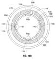
- FIG. 10Bis a fragmentary, transverse cross-sectional view of the interface cuff of FIG. 10A ;
- FIG. 11Ais a fragmentary, axial cross-sectional view of the interface cuff of FIG. 10A , with expansion of the endovascular interface cuff in the aorta to achieve a seal and with retention tine engagement of the aortic wall in the desired recipient site proximal to the aortic aneurysm sac at the level of A-A′;
- FIG. 11Bis a fragmentary, transverse cross-sectional view of the interface cuff of FIG. 11A ;
- FIG. 12is a fragmentary, axial cross-sectional view of the interface cuff of FIG. 10A with delivery of an endograft secured within the rigid cuff of the interface cuff;
- FIG. 13is a fragmentary, axial cross-sectional view of the interface cuff of FIG. 12 with the guidewire removed and with the adjustment tool detached and removed;
- FIG. 14Ais a fragmentary, perspective view of an exemplary embodiment of an actively controllable endograft according to the present invention in which a latticework external to the lumen of an endograft can be radially displaced by controlled rotation of an adjustment member, the lattice structure being in a contracted state;
- FIG. 14Bis a fragmentary, perspective view of the actively controllable endograft of FIG. 14A in which the lattice structure is in an expanded state;
- FIG. 15Ais a side perspective view of an exemplary embodiment of an adjustable vascular cannula according to the present invention.
- FIG. 15Bis a side perspective and partially hidden view of the adjustable vascular cannula of FIG. 15A within a recipient blood vessel with an adjustable seal device in a non-deployed, contracted position;
- FIG. 15Cis a side perspective and partially hidden view of the adjustable vascular cannula of FIG. 15B with the adjustable seal device in a deployed, expanded position.
- Relational terms such as first and second, top and bottom, and the likemay be used solely to distinguish one entity or action from another entity or action without necessarily requiring or implying any actual such relationship or order between such entities or actions.
- the terms “comprises,” “comprising,” or any other variation thereofare intended to cover a non-exclusive inclusion, such that a process, method, article, or apparatus that comprises a list of elements does not include only those elements but may include other elements not expressly listed or inherent to such process, method, article, or apparatus.
- An element proceeded by “comprises . . . a”does not, without more constraints, preclude the existence of additional identical elements in the process, method, article, or apparatus that comprises the element.
- the term “about” or “approximately”applies to all numeric values, whether or not explicitly indicated. These terms generally refer to a range of numbers that one of skill in the art would consider equivalent to the recited values (i.e., having the same function or result). In many instances these terms may include numbers that are rounded to the nearest significant figure.
- FIG. 1a perspective view of an exemplary embodiment of the proximal aspect of a sealable endograft system 1000 according to the present invention, in which the endograft is in a relatively expanded form.
- FIG. 2is a perspective view of the embodiment of the proximal aspect of a sealable endograft system 1000 according to the present invention of FIG. 1 , showing the endograft in a relatively contracted form.
- This exemplary endograft system 1000has the ability to be selectively expanded and contracted to a diameter selected by the implanting physician.
- the endograft system 1000has, along its intermediate extent and, possibly, also at its distal portion (at the downstream end of the prosthesis), a relatively constant diameter portion. At its proximal portion (at the upstream end of the prosthesis), the endograft system 1000 is able to impart a configuration change to selectively adjustable portion of the implant.
- inventive controllable endograft system 1000are described in further detail in U.S. patent application Ser. No. 11/888,009, filed Jul. 31, 2007, and Ser. No. 12/822,291, filed Jun. 24, 2010, which have been incorporated herein and detail of which is not replicated herein for the sake of brevity.
- the exemplary sealable endograft system 1000 shown in FIGS. 1 and 2comprises a hollow tubular endograft body 1005 having an accommodating proximal cuff 1010 and an intermediate, substantially rigid, tubular member 1015 .
- the distal end of such an endograft(not shown in FIGS. 1 and 2 ) may be any or all of accommodating, elastic, rigid, stent-laden, or even replicate the proximal end, depending upon the various exemplary embodiments according to the present invention.
- a selectively adjustable circumferential assembly 1020is disposed at the proximal cuff 1010 .
- the circumferential assembly 1020Contained in one exemplary embodiment of the circumferential assembly 1020 is a circumferential channel enclosing an adjustment member 1025 (indicated only diagrammatically with a solid line).
- the adjustment member 1025causes the expansion/contraction of the accommodating proximal cuff 1010 by looping around the perimeter and by being lengthened or shortened, respectively.
- the adjustment member 1025interacts with a control device 1030 that is operable to cause an increase or decrease in the circumference of the circumferential loop 1025 by the application of rotational torque to the distal aspect of an adjustment tool 1035 emerging from the control device 1030 .
- the adjustment member 1025can be integral with the adjustment tool 1035 in an exemplary embodiment of the circumferential assembly 1020 , or can be removable as shown, for example, in FIG. 10A .
- the adjustment member 1025may take many forms in the present invention.
- the adjustment member 1025is a micro-threaded cable that is fixed at one end to the control device 1030 , which is in the form of a microcylinder, and the adjustment tool 1035 threads through a threaded aspect of the microcylinder 1030 in order to effect a change in the circumference of the proximal cuff 1010 .
- a forwardly imposed torque on the adjustment tool 1035cause expansion of the adjustment tool 1035 .
- Expansion of the adjustment member 1025 in its circumferential extenthas the effect of expanding the proximal aspect of the sealable endograft system 1000 to allow for precise sealing of the sealable endograft system 1000 within a recipient blood vessel such as the aorta (not shown in FIG. 1 or 2 ).
- reverse torque on the adjustment tool 1035has the effect of decreasing the circumference of the circumferential loop of the adjustment member 1025 and, thus, contracting the proximal aspect of the sealable endograft system 1000 , allowing for repositioning as needed.
- the adjustment tool 1035may extend distally through the lumen of the sealable endograft system 1000 .
- the adjustment tool 1035may extend distally through a separate lumen provided in the sealable endograft system 1000 (not shown in FIG. 1 or 2 ).
- FIGS. 3 and 4A to 4Care perspective views of yet another exemplary embodiment of a proximal aspect of a sealable endograft system 1000 according to the present invention that further incorporates a stent or lattice structure 1041 (which, in another embodiment, can be a compressible foam gasket).
- the lattice structure 1041is provided with a lattice interruption 1045 to allow for variations in the circumference of the proximal aspect of the endograft.
- This lattice interruption 1045may take the form of a V-shape as shown in FIGS. 4B and 4C or may be otherwise configured.
- FIGS. 4A to 4Cshow the endograft in a relatively contracted form in FIG. 4A , in a partially expanded form in FIG. 4B , and in a fully expanded form in FIG. 4C .
- the lattice interruption 1045is closed in FIGS.
- One exemplary configuration for the lattice interruption 1045can be a woven material that is stretched in the expanded state and attached to the lattice 1041 and, when allowed to reduce, the woven material resist buckling. This configuration allows the diameter to increase beyond the maximum diameter that the graft will allow with the stent alone.
- FIG. 5Ashows an exemplary embodiment of the control device 1030 in the form of a microcylinder locking mechanism 1050 .
- This locking mechanism 1050is changed from a locked state to an unlocked state by an adjustment tool 1060 , which comprises a tool sheath 1062 having a keyed collar portion 1065 .
- the adjustment tool 1060is fixed, in both the longitudinal and radial extents, to the remote adjustment tool 1035 .
- the progression of FIGS. 5A to 5Cshow how the locking mechanism 1050 is changed from the locked state (in which adjustment of the adjustment member 1025 is prohibited) to the unlocked state (in which adjustment of the adjustment member 1025 is permitted), and, then, back to the locked state.
- the exterior of the locking mechanism 1050is comprised of a microcylinder 1052 having a set of circumferentially spaced-apart, interior striations 1055 .
- the locking mechanism 1050is longitudinally and rotationally fixed to the proximal cuff 1010 .
- a guide bullet 1070is received within the hollow, internally striated microcylinder 1052 .
- the guide bullet 1070has a longitudinal threaded bore that received therein (in a threaded manner) the adjustment member 1025 .
- the adjustment member 1025completely traverses the bore of the guide bullet 1070 and terminates distally of the guide bullet 1070 in a keyed block 1075 that is rotationally fixed to the adjustment member 1025 .
- the guide bullet 1070has at least two opposing, flexible tines 1072 that extend radially outward, in a natural state that, together, has a diameter greater than the internal diameter of the locking microcylinder 1052 (the tines can, as well, be spring loaded outwardly).
- the tines 1072have a terminal portion that is shaped to fit within a corresponding shaped of each striation 1055 within the microcylinder 1052 .
- the tines 1072when the tines 1072 are compressed and the guide bullet 1070 is placed within the microcylinder with the adjustment member 1025 threaded therewithin, the tines 1072 press outwardly against the internal surface of the microcylinder 1052 and, when appropriately rotated therein, the tines 1072 each lock within a respective opposing one of the striations 1055 .
- the tines 1072both form-fittingly and force-fittingly lock within inner striations 1055 when unconstrained. If, for example, there were three tines 1072 separated by 120 degrees each, then the tines 1072 would each lock within a respective one of the striations 1055 that are, also, 120 degrees apart along the interior surface of the microcylinder 1052 .
- the frictional force of the tines 1072 against the inside surface of the microcylinder 1052is sufficiently strong to prevent longitudinal movement of the guide bullet 1070 , even if the keyed block 1075 is rotated unless the tines 1072 are removed from their locked position against the interior surface of the microcylinder.
- the microcylinder 1052 and the guide bullet 1070prevent rotation of the adjustment member 1025 without, not only a particular external force applied thereto, but also a removal of the tines 1072 from the interior surface of the microcylinder 1052 .
- the adjustment tool 1060provides both the ability to rotate the keyed block 1075 but also the ability to separate the tines 1072 from the interior surface of the microcylinder 1052 .
- the tool sheath 1062has a sufficient cylindrical length to slide between the tines 1072 and the interior surface of the microcylinder 1052 anywhere the tines 1072 are contacting the interior surface.
- the longitudinal length of the tool sheath 1062can be, but does not necessarily have to be, as long as the microcylinder 1052 .
- FIG. 5Ashows the microcylinder 1052 with the guide bullet 1070 in a locked position, prior to interface by the remote adjustment tool 1060 .
- the smooth interior surface of the tool sheath 1062first slides along the outer surface of the tines and, then, along and past the distal ends of the tines 1072 , at which time the tines 1072 no longer contact the interior surface of the microcylinder 1052 .
- the orientation of the microcylinder locking mechanism 1050 and the adjustment tool 1060 in FIG. 5Bnow allows for repositioning of the adjustment member 1025 and relocation of the guide bullet 1070 within the microcylinder 1052 .
- the keyed collar portion 1065has a distal taper 1067 that reduces the outer diameter of the tool sheath 1062 inwards to such an extent that it acts as a funnel to direct the keyed block 1075 directly into the radial center of the keyed collar portion 1065 .
- an internal key 1069having an internal circumferential shape corresponding to an external circumferential shape of the keyed block 1075 .
- the tool sheath 1062can pass the tines 1072 (wherever they may be inside the microcylinder 1052 ) sufficiently far to permit the keyed block 1075 to slide along the interior distal taper 1067 and press against the internal bore of the key 1069 .
- the keyed block 1075will fall into the internal bore of the key 1069 in a form-fit, thereby enabling rotation of the adjustment member 1025 (via keyed block 1075 ) in a corresponding manner to any rotation of the adjustment tool 1035 by a user.
- the locking mechanism 1050is longitudinally and rotationally fixed to the circumferential assembly 1020 such that rotation of the locking mechanism 1050 in a first direction causes a contraction of the circumferential assembly 1020 and rotation of the locking mechanism 1050 in the opposition direction causes an expansion of the circumferential assembly 1020 .
- the keyed block 1075is rotated to cause the guide bullet 1070 to advance towards the keyed block 1075 .
- FIG. 5Cshows the microcylinder locking mechanism 1050 with the adjustment tool 1060 after adjustment and disengagement of the microcylinder locking mechanism 1050 by the adjustment tool 1060 with a fixed repositioning of the guide bullet 1070 and a distal lengthening of the adjustment member 1025 with respect to the microcylinder 1052 .
- this exemplary movement of the adjustment member 1025indicates that the circumferential assembly 1020 has reduced in diameter.
- the collar portion 1065 of the remote adjustment tool 1060can contains inner striations (similar to or different from the striations 1055 of the microcylinder 1052 ) that allow it to capture and turn the guide bullet 1070 through removable fixation of the tines 1072 therein (see FIG. 6E ).
- the guide bullet 1070can be fixed rotationally to the adjustment member 1025 .
- the inner striations 1055 of the microcylinder 1052may be grooves, threads, detents, slots, or other surface features sufficient to allow capture of the tines 1072 upon their release as shown in further detail, for example, in the cross-sections of FIGS. 6A to 6G .
- FIG. 6Ais a cross-section along section line A-A of the microcylinder 1052 and guide bullet 1070 of FIG. 5A , in which the tines 1072 having an exemplary triagonal cross-sectional shape are caught within two striations 1055 having an exemplary rectangular cross-sectional shape.
- FIG. 6Bis a cross-section along section line B-B of the tool sheath 1062 of FIG.
- FIG. 6Cis a cross-section along section line C-C of the microcylinder 1052 of FIG. 5B without the adjustment member 1025 depicted.
- FIG. 6Dis a cross-section along section line D-D of the microcylinder 1052 , the guide bullet 1070 , and the tool sheath 1062 of FIG. 5B , in which the tool sheath 1062 captures the guide bullet 1070 and collapses the tines 1072 , thereby removing the tines 1072 from the striations 1055 of the microcylinder 1052 .
- FIG. 6Eshows a cross-sectional view of a variation of another exemplary embodiment of the locking mechanism 1050 ′ with the adjustment tool sheath 1062 ′ also having striations 1055 ′ with an exemplary rectangular cross-sectional shape.
- the tines 1072are illustrated as expanded within two opposing striations 1055 ′ of the tool sheath 1062 ′.
- the tool sheath 1062 ′has a smooth exterior, the tool sheath 1062 ′ can rotate without friction within the microcylinder 1052 ′.
- FIGS. 6F and 6Gshow cross-sectional views of yet another variation of an exemplary embodiment of the microcylinder locking mechanism 1050 ′′ and adjustment tool 1060 ′′.
- the locking mechanism 1050 ′′has a microcylinder 1052 ′′ with striations 1055 ′′ having an exemplary triangular cross-sectional shape.
- the adjustment tool sheath 1062 ′′has a smooth exterior and interior to slide within the microcylinder 1052 ′′ and to slideably capture the tines 1072 ′′′, respectively.
- the tines 1072 ′′are illustrated as expanded within two opposing triangular striations 1055 ′′ of the microcylinder 1052 ′′ in FIG. 6F and are captured within the tool sheath 1062 ′′ in FIG. 6G .
- FIGS. 7A and 7Bshow longitudinal cross-sectional details of one exemplary embodiment of a locking mechanism 1110 for the adjustment tool 1035 according to the present invention.
- FIG. 7Ashows a locking mechanism 1110 comprising a controllable catch 1115 in a disengaged stated.
- FIG. 6Bshows the locking mechanism 1110 with the controllable catch mechanism 1115 engaged.
- FIGS. 8A to 8Cshow details of still another embodiment of a microcylinder locking mechanism 1150 according to the present invention, in which internal locking tines 1152 , 1154 of unequal length are employed to prevent back rotation from torque buildup upon detachment of the remote adjustment tool 1060 .
- FIG. 8Ashows the locking mechanism 1150 comprised of a microcylinder 1151 and a guide bullet 1153 with internal locking tines 1152 , 1154 of unequal length and an associated adjustment tool 1160 having a tool sheath 1164 prior to engagement of the microcylinder locking mechanism 1150 by the tool sheath 1164 .
- FIG. 8Bshows the tool sheath 1164 of FIG.
- FIG. 8Aengaged with the microcylinder locking mechanism 1150 to deflect the tines 1152 , 1154 away from the interior surface of the microcylinder 1151 .
- FIG. 8Cshows the microcylinder locking mechanism 1150 in a locking position different from FIG. 8A after adjustment has occurred and the tool sheath 1164 has been disengaged from the microcylinder 1151 .
- FIGS. 9A and 9Bshow two aspects of details of sheathable retention tines 1130 and a compressible foam sealing gasket 1140 for the proximal terminal aspect of some exemplary embodiments of endografts according to the present invention.
- FIG. 9Ais an axial cross section showing sheathable retention tines 1130 sheathed by an expanded compressible foam gasket 1040 in an exemplary proximal aspect of a sealable endograft system 1000 according to the present invention.
- FIG. 9Bis a perspective view showing sheathable retention tines 1130 exposed and deployed through the compressible foam sealing gasket 1140 disposed at an expanded proximal cuff 1010 in an exemplary endograft according to the present invention.
- the direct pressure of the adjustment member 1025 on the footplate 1145 of the tinesmay be used to extend the sheathable tines 1130 through the compressible foam gasket 1040 and into the wall of a recipient blood vessel.
- direct pressure of the adjustment member 1025may exert force on non-illustrated footplate bands that may be attached to or adjacent the footplates 1145 of the tines 1130 and may be used to extend the sheathable tines 1130 through the compressible foam gasket 1040 and into the wall of a recipient blood vessel.
- footplate bandsmay, themselves, be the base of the sheathable tines 1130 in certain exemplary embodiments of the present invention.
- the adjustment member 1025may course though eyelets, other brackets or may otherwise be movably connected to the footplates 1145 to maintain equal pressure and desired orientation upon expansion of the adjustment member loop.
- the distal attachment of the endograft to the aortic wall distal to the aneurysm sacmay be accomplished in a conventional manner using an expandable lattice component at the distal cuffs, or variations on the adjustable, sealable mechanism disclosed herein may be employed to secure distal seals.
- the distal sealsare subject to lower pressure demands, and the anatomic constraints of sufficient aortic neck distally are generally less problematic than for the proximal seal.
- FIGS. 10 to 13provide anatomic views of another exemplary embodiment of an endograft implant according to the present invention in which the implant is a universal proximal cuff endovascular implant for treatment of an abdominal aortic aneurysm.
- the implantis a universal proximal cuff endovascular implant for treatment of an abdominal aortic aneurysm.
- Endografts with the features shown in the various embodiments of the present inventionhave unique abilities to accommodate to anatomic variations that would preclude or compromise use of conventional endograft systems.
- the universal proximal cuff implants of the present inventionallow an operator to make use of their ability to securely seal and attach in anatomic sites where conventional endografts cannot be securely placed, and then allow a conventional endograft to securely dock with the universal proximal cuff endovascular implants distally.
- Universal proximal cuff endovascular implants of the present inventionmay be provided with any of the elements disclosed in the present and the incorporated co-pending applications referenced herein.
- Such elementsinclude, but are not limited to, attachment of radio-opaque monitoring clip assemblies on the outer surfaces of endografts to allow post-implantation monitoring of slippage or endoleak formation by plain radiographs, steerable delivery systems to permit delivery and seal of an endograft in an anatomically angulated or irregular site, and/or auto-accommodation for post-implantation aortic remodeling,
- FIG. 10Ais an axial cross-sectional view of an exemplary endovascular universal interface cuff 1155 of the present invention to be implanted into an aorta having an aneurysm sac 1170 and an aortic wall 1175 .
- the universal endovascular interface cuff 1155has been positioned over an endovascular guidewire 1160 to a desired recipient site A-A′ proximal to the aortic aneurysm sac 1170 .
- the endovascular universal interface cuff 1155further comprises an accommodating proximal cuff 1010 and a rigid distal cuff 1200 .
- FIG. 10Bprovides a transverse cross-sectional view of the exemplary endovascular interface cuff 1155 of FIG. 10A at the level of A-A′ in FIG. 10A .
- the compressible foam gasket 1140is uncompressed and, therefore, covers the retention tines 1165 .
- the adjustment member 1025courses in a circumferential loop through eyelets 1180 attached to a series of compression footplates 1185 .
- the compression footplates 1185serve to maintain an orientation of the expanding circumferential loop 1035 in a plane transverse to the aortic lumen 1190 , and present a broader pressure contact with the underlying aortic wall 1175 when the circumferential assembly is expanded.
- the compression footplates 1185may abut, be attached to, or be contiguous with the retention tines 1165 , which are displaced through the compressed compressible foam gasket 1140 and allowed to enter the aortic wall 1175 for overall device stabilization and retention. While four retention tines 1165 and footplates 1185 are shown, this embodiment is merely exemplary and can be any number.
- FIG. 11Ashows the same axial cross-sectional view of the endovascular universal interface cuff 1155 of FIG. 10A but after the universal endovascular interface cuff 1155 has expanded to achieve a seal in the aortic wall 1175 . Due to the expansion of the cuff, the foam gasket 1140 becomes compressed, allowing the retention tines 1165 to protrude radially outward to engage the aortic wall 1175 in the desired recipient site A-A′ proximal to the aortic aneurysm sac 1170 . In the exemplary embodiment shown in FIG. 11B , the adjustment member 1025 has expanded to move the eyelets 1180 attached to the footplates 1185 outwards.
- the interior lumen of the circumferential assembly 1020 shown in FIG. 11Bhas increased substantially as compared to the state shown in FIG. 10B .
- the compression of the foam gasket 1140 and the engagement of the aortic wall 1175 by the retention tines 1165creates a firm seal between the universal endovascular interface cuff 1155 and the aortic wall 1175 .
- FIG. 12shows the same axial cross-sectional axial of the universal endovascular interface cuff 1155 of the present invention as in FIGS. 10A and 11A but with delivery of a conventional endograft 1300 into the aortic wall 1175 , which endograft 1300 has been secured within the rigid distal cuff 1200 of the universal endovascular interface cuff 1155 .
- the endograft 1300can include an expandable lattice 1310 .
- FIG. 13shows the same cross-sectional axial view of an exemplary universal endovascular interface cuff 1155 of the present invention as FIG. 12 but after removal of the endovascular guidewire 1160 and detachment and removal of the adjustment member 1025 .
- Such removal and detachmentcan be carried out by a release mechanism 1037 .
- the distal attachment of the conventional endograftis not shown in FIGS. 12 and 13 , but can be accomplished in the usual manner for conventional endograft implantation sufficient to prevent backfill of the aneurysm sac 1170 from the distal aorta or the iliac vessels.
- the rigid distal cuff 1200includes, at its exterior, exemplary radio-opaque monitoring clip assemblies 1225 to allow post-implantation monitoring of slippage or endoleak formation and/or auto-accommodation for post-implantation aortic remodeling.
- the rigid distal cuff 1200can be provided with interior graft retention tines 1227 that add to securing, without leaks, the endograft 1300 to the interior of the rigid distal cuff 1200 .
- the tubular endograft body 1005 , the proximal cuff 1010 , the rigid distal cuffs 1200 , and the endograft body 1300 as described hereinmay be constructed of solid, woven, non-woven, or mesh materials such as, but not limited to, natural or synthetic rubbers, nylon, GORE-TEX®, elastomers, polyisoprenes, polyphosphazenes, polyurethanes, vinyl plastisols, acrylic polyesters, polyvinylpyrrolidone-polyurethane interpolymers, butadiene rubbers, styrene-butadiene rubbers, rubber lattices, DACRON®, PTFE, malleable metals, other biologically compatible materials or a combination of such biologically compatible materials in a molded, woven, or non-woven configuration, coated, non-coated, and other polymers or materials with suitable resilience and pliability qualities.
- natural or synthetic rubberssuch as, but not limited to
- the non-elastic tubular member 1015 and corresponding structuresit is desirable for the non-elastic tubular member 1015 and corresponding structures to be pliable to allow for folding or compressibility without allowing elasticity. In certain exemplary embodiments according to the present invention, it is desirable for the accommodating proximal cuff 1010 and corresponding structures to have plasticity and be compressible or foldable. In any given exemplary embodiment, the non-elastic tubular implant body 1015 , the endograft body 1300 , the accommodating proximal cuff 1010 , and corresponding structures may be constructed of the same material of varying elasticity, or these structures may be constructed of different, but compatible materials.
- the adjustment members 1025 , the retention tines 1130 , 1165 , and the microcylinders 1030 and other mechanical components as disclosed herein and in all other embodiments of the present inventionmay be fabricated of any suitably strong biocompatible material, including, but not limited to titanium, stainless steel, cobalt chromium alloys, other metals, other metal alloys, nitinol, plastics, or ceramics.
- the adjustment members 1025 , the retention tines 1130 , 1165 , and the microcylinders 1030 and other mechanical componentsmay be milled, laser cut, lathed, molded, or extruded.
- the compressible foam gaskets 1140 as disclosed hereinmay be any biocompatible foam material of either an open or closed cell structure with sufficient compressibility and resilience to allow rapid recovery in a non-compressed state.
- foam materialsmay be viscoelastic foam with a compressible cellular material that has both elastic (spring-like) and viscous (time-dependent) properties. Viscoelastic foam differs from regular foam by having time-dependent behaviors such as creep, stress relaxation, and hysteresis.
- FIGS. 14A and 14Bshow an alternate exemplary embodiment of a sealable endograft system 2000 according to the present invention in two different states.
- a hinged lattice structure 2100is attached to an internal or external surface of at least the proximal portion 2210 of an endograft body 2200 (the “lattice” in these figures is only diagrammatic and is not intended to imply that the only possible number of rings of lattice is greater than one).
- Either the lattice structure 2100 or the endograft body 2200can be provided with radially displaced retention tines 2105 that, in a non-distended state of the proximal portion 2210 , can be covered within a compressible foam gasket 2300 .
- the distal portion 2220 of the endograft body 2200comprises a non-distensible material and the proximal portion 2210 of the endograft body 2200 is an accommodating cuff comprising a distensible material forming the proximally terminal aspect of the sealable endograft system 2000 and enclosing the terminal hinged lattice structure 2100 therewithin.
- a control system 2400 or jack screw shown in FIGS. 14A and 14Bis provided to expand and contract the lattice structure 2100 .
- a torque wire 2410can be fixed at two points 2420 , 2430 longitudinally separate from one another on the lattice structure 2100 .
- This torque wire 2410has exterior threads that correspond to threaded bores of one of the two points 2420 , 2430 . Accordingly, when the torque wire 2410 is rotated, the two points 2420 , 2430 of the lattice either approach one another (to expand the proximal portion 2210 ) or retreat from one another (to contract the proximal portion 2210 ) this imparts motion to all contiguously interconnected lattice elements.
- proximal end point 2430be bored for rotation but fixed longitudinally.
- a smooth-bored collar 2440is fixed to the wall of the graft 2200 , for example, on an interior surface distal of the lattice structure 2100 .
- the lattice structure of the present inventionis able to actively open according to the desire of the user surgeon implanting the prosthesis.
- the opening performed by prior art self-expanding stent structures in endograft prosthesisare referred to herein as “passive opening” or “passive expansion”.
- the expansion performed by the inventive controllable, hinged, lattice structure of the present invention for the disclosed endograft prosthesesis referred to herein as “active control” or “active expansion” because it can be actively controlled in both the expansion and contraction directions according to the desire of the user.
- active controlor “active expansion” because it can be actively controlled in both the expansion and contraction directions according to the desire of the user.
- Thisis further in contrast to expansion of stent structures using balloon, which case is referred to as “balloon opening” or “balloon expansion” because it occurs only in one direction (expansion) without any ability to contract actively.
- the single embodiment of the jack screw shown in FIGS. 14A and 14Bcan be replicated any number of times about the circumference of the lattice structure 2100
- FIGS. 10A to 11Bcan be incorporated into the system of FIGS. 14A and 14B to create a hybrid system.
- the circumferential assembly 1020can be positioned at the proximal end of the endograft and action of the circumferential loop 1035 within the proximal cuff 1010 , can be used to expand and contract the latticework 2100 .
- FIG. 15Ais a lateral view of an exemplary embodiment of an adjustable vascular cannula 1230 according to the present invention.
- an adjustable vascular cannula 1230is a generally tubular structure with external cannula walls 1235 defining a cannula lumen 1240 , and comprises a port end 1245 , a cannula body 1250 , and a cannula tip 1255 .
- the cannula body 1250is further provided with a delivery recess 1260 in its external wall structure at or near the junction of the cannula tip 1255 .
- 15Acomprises an adjustable seal device 1265 attached to an adjustment member 1025 such as a torque wire that extends beyond the port end 1245 of the adjustable vascular cannula 1230 as shown in FIG. 15B .
- the adjustment member 1025may course through the cannula lumen 1240 , or it may course through an accessory lumen (not shown in FIG. 15A or 15B ) within the cannula wall 1235 substantially parallel to the cannula lumen 1240 , or it may course externally to the adjustable vascular cannula 1230 as shown partially within and partially outside the lumen 1240 in FIG. 15B .
- the adjustable seal device 1265is substantially flush with the outer diameter of the cannula walls 1235 within the delivery recess 1260 of the cannula body 1250 .
- FIG. 15Cshows the adjustable seal device 1265 in a deployed state, which is the result of torque applied externally to the adjustment member 1025 by a user.
- the adjustable seal device 1265further comprises a hinged adjustable latticework 1270 covered by a sealing cuff 1275 which is constructed of a distensible material.
- the adjustment member 1025terminates, for example, in a circumferential loop 1035 within the sealing cuff 1275 , where it may be further covered by a compressible foam gasket 1140 .
- the adjustment member 1025may further pass through a locking mechanism 1050 as disclosed elsewhere herein which serves to regulate the torque applied to the circumferential loop 1035 .
- the hinged adjustable latticework 1270may further be provided with one or more retention tines 1130 , 1165 , which are radially displaced from the terminal aspect of the hinged adjustable latticework 1270 , and which are enclosed within and covered by the compressible foam gasket 1140 when the adjustable seal device 1265 is not distended.
- the diameter of the circumferential loop 1035is increased, displacing the hinged adjustable latticework 1270 as shown in FIG. 15C until the compressible foam gasket 1140 and the sealing cuff 1275 is able to firmly engage the inner wall 1190 of a recipient blood vessel 1175 .
- the retention tines 1130 , 1165may be provided to engage the vessel wall 1190 in a substantially straight manner or at angles varying from about 1 degree to about 179 degrees.
- the retention tines 1130 , 1165may be angled axially or longitudinally in various embodiments according to the present invention.
- the torque of the adjustment member 1025may be reversed, collapsing the adjustable seal device 1165 , and allowing the compressible foam gasket 1140 to re-expand, thus withdrawing the retention tines 1165 from the vessel wall 1175 and covering the retention tines 1165 to allow atraumatic cannula withdrawal.
Landscapes
- Health & Medical Sciences (AREA)
- Engineering & Computer Science (AREA)
- Biomedical Technology (AREA)
- Life Sciences & Earth Sciences (AREA)
- General Health & Medical Sciences (AREA)
- Veterinary Medicine (AREA)
- Public Health (AREA)
- Heart & Thoracic Surgery (AREA)
- Vascular Medicine (AREA)
- Animal Behavior & Ethology (AREA)
- Transplantation (AREA)
- Oral & Maxillofacial Surgery (AREA)
- Cardiology (AREA)
- Surgery (AREA)
- Gastroenterology & Hepatology (AREA)
- Pulmonology (AREA)
- Reproductive Health (AREA)
- Nuclear Medicine, Radiotherapy & Molecular Imaging (AREA)
- Medical Informatics (AREA)
- Molecular Biology (AREA)
- Neurosurgery (AREA)
- Prostheses (AREA)
Abstract
Description
- claims the priority, under 35 U.S.C. §119, of U.S. Provisional Patent Application No. 61/428,114, filed Dec. 29, 2010;
- is a continuation-in-part of co-pending U.S. patent application Ser. No. 11/888,009, filed Jul. 31, 2007, now U.S. Pat. No. 8,252,036, which application claims priority to U.S. Provisional Patent Application No. 60/834,401, filed Jul. 31, 2006 and 60/834,627, filed Aug. 1, 2006; and
- is a continuation-in-part of co-pending U.S. patent application Ser. No. 12/822,291, filed Jun. 24, 2010, now U.S. Pat. No. 9,408,607, which application claims priority to U.S. Provisional Patent Application No. 61/222,646, filed Jul. 2, 2009,
the prior applications are herewith incorporated by reference herein in their entireties.
Claims (7)
Priority Applications (18)
| Application Number | Priority Date | Filing Date | Title |
|---|---|---|---|
| US13/339,236US9585743B2 (en) | 2006-07-31 | 2011-12-28 | Surgical implant devices and methods for their manufacture and use |
| EP11854121.8AEP2658478B1 (en) | 2010-12-29 | 2011-12-29 | Improved surgical implant devices |
| JP2013547654AJP2014507200A (en) | 2010-12-29 | 2011-12-29 | Improved surgical implant devices and methods for their manufacture and use |
| EP19197565.5AEP3646818B1 (en) | 2010-12-29 | 2011-12-29 | Improved surgical implant devices |
| CA2823328ACA2823328C (en) | 2010-12-29 | 2011-12-29 | Improved surgical implant devices and methods for their manufacture and use |
| CN202010057584.1ACN111195163B (en) | 2010-12-29 | 2011-12-29 | Improved surgical implant devices and methods of making and using the same |
| CN201180068672.0ACN103491899B (en) | 2010-12-29 | 2011-12-29 | Improved surgical implant device and methods of making and using the same |
| EP23213164.9AEP4306085A3 (en) | 2010-12-29 | 2011-12-29 | Improved surgical implant devices |
| CN201710165135.7ACN107242891B (en) | 2010-12-29 | 2011-12-29 | Improved surgical implant devices and methods of making and using the same |
| KR1020137019803AKR101814855B1 (en) | 2010-12-29 | 2011-12-29 | Improved surgical implant devices and methods for their manufacture and use |
| PCT/US2011/067695WO2012092408A1 (en) | 2010-12-29 | 2011-12-29 | Improved surgical implant devices and methods for their manufacture and use |
| KR1020177037198AKR101953056B1 (en) | 2010-12-29 | 2011-12-29 | Improved surgical implant devices and methods for their manufacture and use |
| US13/656,717US9566178B2 (en) | 2010-06-24 | 2012-10-21 | Actively controllable stent, stent graft, heart valve and method of controlling same |
| US13/772,203US9814611B2 (en) | 2007-07-31 | 2013-02-20 | Actively controllable stent, stent graft, heart valve and method of controlling same |
| US15/448,417US10507097B2 (en) | 2006-07-31 | 2017-03-02 | Surgical implant devices and methods for their manufacture and use |
| US16/716,416US11540911B2 (en) | 2010-12-29 | 2019-12-16 | Surgical implant devices and methods for their manufacture and use |
| US18/086,059US12329630B2 (en) | 2010-12-29 | 2022-12-21 | Surgical implant devices and methods for their manufacture and use |
| US19/217,218US20250281275A1 (en) | 2010-12-29 | 2025-05-23 | Surgical implant devices and methods for their manufacture and use |
Applications Claiming Priority (7)
| Application Number | Priority Date | Filing Date | Title |
|---|---|---|---|
| US83440106P | 2006-07-31 | 2006-07-31 | |
| US83462706P | 2006-08-01 | 2006-08-01 | |
| US11/888,009US8252036B2 (en) | 2006-07-31 | 2007-07-31 | Sealable endovascular implants and methods for their use |
| US22264609P | 2009-07-02 | 2009-07-02 | |
| US12/822,291US9408607B2 (en) | 2009-07-02 | 2010-06-24 | Surgical implant devices and methods for their manufacture and use |
| US201061428114P | 2010-12-29 | 2010-12-29 | |
| US13/339,236US9585743B2 (en) | 2006-07-31 | 2011-12-28 | Surgical implant devices and methods for their manufacture and use |
Related Parent Applications (3)
| Application Number | Title | Priority Date | Filing Date |
|---|---|---|---|
| US11/888,009Continuation-In-PartUS8252036B2 (en) | 2006-07-31 | 2007-07-31 | Sealable endovascular implants and methods for their use |
| US12/822,291Continuation-In-PartUS9408607B2 (en) | 2006-07-31 | 2010-06-24 | Surgical implant devices and methods for their manufacture and use |
| US13/544,379Continuation-In-PartUS9138335B2 (en) | 2006-07-31 | 2012-07-09 | Surgical implant devices and methods for their manufacture and use |
Related Child Applications (2)
| Application Number | Title | Priority Date | Filing Date |
|---|---|---|---|
| US12/822,291Continuation-In-PartUS9408607B2 (en) | 2006-07-31 | 2010-06-24 | Surgical implant devices and methods for their manufacture and use |
| US15/448,417ContinuationUS10507097B2 (en) | 2006-07-31 | 2017-03-02 | Surgical implant devices and methods for their manufacture and use |
Publications (2)
| Publication Number | Publication Date |
|---|---|
| US20120239133A1 US20120239133A1 (en) | 2012-09-20 |
| US9585743B2true US9585743B2 (en) | 2017-03-07 |
Family
ID=46383523
Family Applications (5)
| Application Number | Title | Priority Date | Filing Date |
|---|---|---|---|
| US13/339,236Active2030-03-24US9585743B2 (en) | 2006-07-31 | 2011-12-28 | Surgical implant devices and methods for their manufacture and use |
| US15/448,417Active2032-10-21US10507097B2 (en) | 2006-07-31 | 2017-03-02 | Surgical implant devices and methods for their manufacture and use |
| US16/716,416Active2032-03-28US11540911B2 (en) | 2010-12-29 | 2019-12-16 | Surgical implant devices and methods for their manufacture and use |
| US18/086,059Active2032-09-05US12329630B2 (en) | 2010-12-29 | 2022-12-21 | Surgical implant devices and methods for their manufacture and use |
| US19/217,218PendingUS20250281275A1 (en) | 2010-12-29 | 2025-05-23 | Surgical implant devices and methods for their manufacture and use |
Family Applications After (4)
| Application Number | Title | Priority Date | Filing Date |
|---|---|---|---|
| US15/448,417Active2032-10-21US10507097B2 (en) | 2006-07-31 | 2017-03-02 | Surgical implant devices and methods for their manufacture and use |
| US16/716,416Active2032-03-28US11540911B2 (en) | 2010-12-29 | 2019-12-16 | Surgical implant devices and methods for their manufacture and use |
| US18/086,059Active2032-09-05US12329630B2 (en) | 2010-12-29 | 2022-12-21 | Surgical implant devices and methods for their manufacture and use |
| US19/217,218PendingUS20250281275A1 (en) | 2010-12-29 | 2025-05-23 | Surgical implant devices and methods for their manufacture and use |
Country Status (7)
| Country | Link |
|---|---|
| US (5) | US9585743B2 (en) |
| EP (3) | EP2658478B1 (en) |
| JP (1) | JP2014507200A (en) |
| KR (2) | KR101814855B1 (en) |
| CN (3) | CN111195163B (en) |
| CA (1) | CA2823328C (en) |
| WO (1) | WO2012092408A1 (en) |
Cited By (22)
| Publication number | Priority date | Publication date | Assignee | Title |
|---|---|---|---|---|
| DE102017121251A1 (en)* | 2017-09-13 | 2019-03-14 | Universitätsmedizin Der Johannes Gutenberg-Universität Mainz | catheter |
| US10478324B2 (en) | 2014-08-12 | 2019-11-19 | W. L. Gore & Associates, Inc. | Handle for medical device deployment |
| US10695203B2 (en) | 2012-02-14 | 2020-06-30 | W. L. Gore & Associates, Inc. | Endoprosthesis having aligned legs for ease of cannulation |
| US10744015B2 (en) | 2016-08-24 | 2020-08-18 | W. L. Gore & Associates, Inc. | Sleeves for expandable medical devices |
| US10751205B1 (en) | 2013-03-05 | 2020-08-25 | W. L. Gore & Associates, Inc. | Tapered sleeve |
| US10765543B2 (en) | 2014-04-04 | 2020-09-08 | W. L. Gore & Associates, Inc. | Deployment handle for a medical device deployment system |
| US10888414B2 (en) | 2019-03-20 | 2021-01-12 | inQB8 Medical Technologies, LLC | Aortic dissection implant |
| US10987234B2 (en) | 2011-08-12 | 2021-04-27 | W. L. Gore & Associates, Inc. | Devices and methods for approximating the cross-sectional profile of vasculature having branches |
| US11123174B2 (en) | 2012-03-13 | 2021-09-21 | W. L. Gore & Associates, Inc. | External steerable fiber for use in endoluminal deployment of expandable devices |
| US11166806B2 (en) | 2014-01-10 | 2021-11-09 | W. L. Gore & Associates, Inc. | Implantable intraluminal device |
| US11213415B2 (en) | 2017-02-14 | 2022-01-04 | W. L. Gore & Associates, Inc. | Medical device delivery systems and methods |
| US11229539B2 (en) | 2011-08-12 | 2022-01-25 | W. L. Gore & Associates, Inc. | Evertable sheath devices, systems, and methods |
| US11266418B2 (en) | 2016-08-05 | 2022-03-08 | W. L. Gore & Associates, Inc. | Integrated medical device constraining lumen |
| US11324615B2 (en) | 2011-11-14 | 2022-05-10 | W. L. Gore & Associates, Inc. | External steerable fiber for use in endoluminal deployment of expandable devices |
| US11382781B2 (en) | 2011-11-14 | 2022-07-12 | W. L. Gore & Associates, Inc. | External steerable fiber for use in endoluminal deployment of expandable devices |
| US11432952B2 (en) | 2013-03-07 | 2022-09-06 | W. L. Gore & Associates, Inc. | Implantable medical devices and related delivery systems |
| US11540933B2 (en) | 2017-10-11 | 2023-01-03 | W. L. Gore & Associates, Inc. | Implantable medical device constraint and deployment apparatus |
| US11564788B1 (en) | 2015-10-13 | 2023-01-31 | W. L. Gore & Associates, Inc. | Single site access aortic aneurysm repair method |
| US11690742B2 (en) | 2014-04-04 | 2023-07-04 | W. L. Gore & Associates, Inc. | Delivery and deployment systems for bifurcated stent grafts |
| US11801155B2 (en) | 2014-03-06 | 2023-10-31 | W. L. Gore & Associates, Inc. | Implantable medical device constraint and deployment apparatus |
| US12310869B2 (en) | 2017-03-08 | 2025-05-27 | W. L. Gore & Associates, Inc. | Steering wire attach for angulation |
| US12409054B2 (en) | 2018-08-31 | 2025-09-09 | W. L. Gore & Associates, Inc. | Pivot delivery system for implantable medical device |
Families Citing this family (8)
| Publication number | Priority date | Publication date | Assignee | Title |
|---|---|---|---|---|
| EP2929859A1 (en) | 2014-04-10 | 2015-10-14 | Carag AG | A kit for placing a bypass |
| CN106859716B (en)* | 2017-03-02 | 2023-03-14 | 福建医科大学附属协和医院 | Pancreas intestines anastomat |
| US10722351B2 (en)* | 2017-08-24 | 2020-07-28 | Medtronic Vascular, Inc. | Transcatheter prosthesis with sealing component, and systems and methods for delivering and deployment thereof |
| US10709556B2 (en) | 2017-08-24 | 2020-07-14 | Medtronic Vascular, Inc. | Transcatheter prosthesis with sealing component, and systems and methods for delivering and deployment thereof |
| US11051824B2 (en)* | 2017-09-28 | 2021-07-06 | Microvention, Inc. | Embolic delivery |
| US10531883B1 (en)* | 2018-07-20 | 2020-01-14 | Syntheon 2.0, LLC | Aspiration thrombectomy system and methods for thrombus removal with aspiration catheter |
| WO2021178401A1 (en)* | 2020-03-03 | 2021-09-10 | The Regents Of The University Of California | Cerebral dural venous sinus stent |
| CN115040183B (en)* | 2022-06-09 | 2024-04-19 | 广州新诚生物科技有限公司 | Urinary surgery is with bladder urethra anastomotic device |
Citations (323)
| Publication number | Priority date | Publication date | Assignee | Title |
|---|---|---|---|---|
| US2684069A (en) | 1952-07-05 | 1954-07-20 | Donaldson | Precision linear-fracture instrument for heart valve surgery |
| US3490975A (en) | 1965-10-18 | 1970-01-20 | Univ Of Birmingham The | Method of making an artificial artery of wound silicone rubber thread |
| US3657744A (en) | 1970-05-08 | 1972-04-25 | Univ Minnesota | Method for fixing prosthetic implants in a living body |
| US3667474A (en) | 1970-01-05 | 1972-06-06 | Konstantin Vasilievich Lapkin | Dilator for performing mitral and tricuspidal commissurotomy per atrium cordis |
| US4056854A (en) | 1976-09-28 | 1977-11-08 | The United States Of America As Represented By The Department Of Health, Education And Welfare | Aortic heart valve catheter |
| US4323525A (en) | 1978-04-19 | 1982-04-06 | Imperial Chemical Industries Limited | Electrostatic spinning of tubular products |
| US4459252A (en) | 1975-05-09 | 1984-07-10 | Macgregor David C | Method of forming a small bore flexible vascular graft involving eluting solvent-elutable particles from a polymeric tubular article |
| US4475972A (en) | 1981-10-01 | 1984-10-09 | Ontario Research Foundation | Implantable material |
| US4585000A (en) | 1983-09-28 | 1986-04-29 | Cordis Corporation | Expandable device for treating intravascular stenosis |
| US4602911A (en) | 1982-08-19 | 1986-07-29 | General Resorts S.A. | Adjustable ringprosthesis |
| US4655771A (en) | 1982-04-30 | 1987-04-07 | Shepherd Patents S.A. | Prosthesis comprising an expansible or contractile tubular body |
| US4800882A (en) | 1987-03-13 | 1989-01-31 | Cook Incorporated | Endovascular stent and delivery system |
| US4851009A (en) | 1985-12-16 | 1989-07-25 | Corvita Corporation | Crack prevention of implanted prostheses |
| US4906244A (en) | 1988-10-04 | 1990-03-06 | Cordis Corporation | Balloons for medical devices and fabrication thereof |
| US4921484A (en) | 1988-07-25 | 1990-05-01 | Cordis Corporation | Mesh balloon catheter device |
| US4990151A (en) | 1988-09-28 | 1991-02-05 | Medinvent S.A. | Device for transluminal implantation or extraction |
| US5019090A (en) | 1988-09-01 | 1991-05-28 | Corvita Corporation | Radially expandable endoprosthesis and the like |
| US5061275A (en) | 1986-04-21 | 1991-10-29 | Medinvent S.A. | Self-expanding prosthesis |
| US5092877A (en) | 1988-09-01 | 1992-03-03 | Corvita Corporation | Radially expandable endoprosthesis |
| US5133742A (en) | 1990-06-15 | 1992-07-28 | Corvita Corporation | Crack-resistant polycarbonate urethane polymer prostheses |
| US5163951A (en) | 1990-12-27 | 1992-11-17 | Corvita Corporation | Mesh composite graft |
| US5180368A (en) | 1989-09-08 | 1993-01-19 | Advanced Cardiovascular Systems, Inc. | Rapidly exchangeable and expandable cage catheter for repairing damaged blood vessels |
| WO1993008767A1 (en) | 1991-11-05 | 1993-05-13 | New England Deaconess Hospital Corporation | Method and device for performing endovascular repair of aneurysms |
| US5229431A (en) | 1990-06-15 | 1993-07-20 | Corvita Corporation | Crack-resistant polycarbonate urethane polymer prostheses and the like |
| WO1994006372A1 (en) | 1992-09-14 | 1994-03-31 | Meadox Medicals, Inc. | A radially self-expanding implantable intraluminal device |
| WO1995005132A1 (en) | 1993-08-18 | 1995-02-23 | W.L. Gore & Associates, Inc. | An intraluminal stent graft |
| WO1995005131A1 (en) | 1993-08-18 | 1995-02-23 | W.L. Gore & Associates, Inc. | A tubular intraluminal graft |
| US5411552A (en) | 1990-05-18 | 1995-05-02 | Andersen; Henning R. | Valve prothesis for implantation in the body and a catheter for implanting such valve prothesis |
| US5425705A (en) | 1993-02-22 | 1995-06-20 | Stanford Surgical Technologies, Inc. | Thoracoscopic devices and methods for arresting the heart |
| US5441516A (en) | 1994-03-03 | 1995-08-15 | Scimed Lifesystems Inc. | Temporary stent |
| US5443477A (en) | 1994-02-10 | 1995-08-22 | Stentco, Inc. | Apparatus and method for deployment of radially expandable stents by a mechanical linkage |
| US5449372A (en) | 1990-10-09 | 1995-09-12 | Scimed Lifesystems, Inc. | Temporary stent and methods for use and manufacture |
| US5456667A (en) | 1993-05-20 | 1995-10-10 | Advanced Cardiovascular Systems, Inc. | Temporary stenting catheter with one-piece expandable segment |
| US5456694A (en) | 1994-05-13 | 1995-10-10 | Stentco, Inc. | Device for delivering and deploying intraluminal devices |
| US5484565A (en) | 1991-05-21 | 1996-01-16 | Namic Caribe, Inc. | Method for making a medical catheter |
| US5531785A (en) | 1994-05-06 | 1996-07-02 | Autogenics, Inc. | Prosthetic heart valve holder |
| US5554183A (en) | 1994-01-19 | 1996-09-10 | Nazari; Stefano | Vascular prosthesis for the substitution or internal lining of blood vessels of medium or large diameter and device for its application |
| WO1996033066A1 (en) | 1995-04-17 | 1996-10-24 | Baxter International Inc. | Radially-enlargeable ptfe tape-reinforced vascular grafts and their methods of manufacture |
| US5575818A (en) | 1995-02-14 | 1996-11-19 | Corvita Corporation | Endovascular stent with locking ring |
| US5591196A (en) | 1994-02-10 | 1997-01-07 | Endovascular Systems, Inc. | Method for deployment of radially expandable stents |
| US5593417A (en) | 1995-11-27 | 1997-01-14 | Rhodes; Valentine J. | Intravascular stent with secure mounting means |
| US5617878A (en) | 1996-05-31 | 1997-04-08 | Taheri; Syde A. | Stent and method for treatment of aortic occlusive disease |
| WO1997012562A1 (en) | 1995-10-03 | 1997-04-10 | Medtronic, Inc. | Modular intraluminal prostheses construction and methods |
| US5628788A (en) | 1995-11-07 | 1997-05-13 | Corvita Corporation | Self-expanding endoluminal stent-graft |
| WO1997017899A1 (en) | 1995-11-13 | 1997-05-22 | Corvita Corporation | Endoluminal prosthesis deployment device for use with prostheses of variable length and having retraction ability |
| US5632772A (en) | 1993-10-21 | 1997-05-27 | Corvita Corporation | Expandable supportive branched endoluminal grafts |
| US5639278A (en) | 1993-10-21 | 1997-06-17 | Corvita Corporation | Expandable supportive bifurcated endoluminal grafts |
| WO1997021403A1 (en) | 1995-12-14 | 1997-06-19 | Prograft Medical, Inc. | Kink-resistant stent graft |
| WO1997025000A1 (en) | 1996-01-04 | 1997-07-17 | Endo Vascular Technologies, Inc | Flat wire stent |
| WO1997026829A1 (en) | 1996-01-24 | 1997-07-31 | S.M.T. (Medical Technologies) Ltd. | Surgical implement particularly useful for implanting prosthetic heart valves |
| WO1997033532A2 (en) | 1996-03-13 | 1997-09-18 | Medtronic, Inc. | Endoluminal prostheses and therapies for multiple-branch body lumen systems |
| US5693088A (en) | 1993-11-08 | 1997-12-02 | Lazarus; Harrison M. | Intraluminal vascular graft |
| US5713907A (en) | 1995-07-20 | 1998-02-03 | Endotex Interventional Systems, Inc. | Apparatus and method for dilating a lumen and for inserting an intraluminal graft |
| US5713948A (en) | 1995-07-19 | 1998-02-03 | Uflacker; Renan | Adjustable and retrievable graft and graft delivery system for stent-graft system |
| US5718159A (en) | 1996-04-30 | 1998-02-17 | Schneider (Usa) Inc. | Process for manufacturing three-dimensional braided covered stent |
| US5720776A (en) | 1991-10-25 | 1998-02-24 | Cook Incorporated | Barb and expandable transluminal graft prosthesis for repair of aneurysm |
| US5723004A (en) | 1993-10-21 | 1998-03-03 | Corvita Corporation | Expandable supportive endoluminal grafts |
| US5725547A (en) | 1996-01-04 | 1998-03-10 | Chuter; Timothy A. M. | Corrugated stent |
| EP0836451A1 (en) | 1995-06-07 | 1998-04-22 | Endovascular Technologies, Inc. | Intraluminal grafting system |
| US5797951A (en) | 1995-08-09 | 1998-08-25 | Mueller; Edward Gene | Expandable support member |
| WO1998041167A1 (en) | 1997-03-14 | 1998-09-24 | Harry Bernard Joseph Spoelstra | Arrangement for the endovascular repair of a blood vessel section |
| US5824040A (en) | 1995-12-01 | 1998-10-20 | Medtronic, Inc. | Endoluminal prostheses and therapies for highly variable body lumens |
| WO1998049974A1 (en) | 1997-05-05 | 1998-11-12 | Sulzer Carbomedics Inc. | Low profile introducer and rotator for a heart valve prosthesis |
| US5840081A (en) | 1990-05-18 | 1998-11-24 | Andersen; Henning Rud | System and method for implanting cardiac valves |
| US5855565A (en) | 1997-02-21 | 1999-01-05 | Bar-Cohen; Yaniv | Cardiovascular mechanically expanding catheter |
| US5855598A (en) | 1993-10-21 | 1999-01-05 | Corvita Corporation | Expandable supportive branched endoluminal grafts |
| WO1999015108A2 (en) | 1997-09-24 | 1999-04-01 | Med Institute, Inc. | Radially expandable stent |
| US5928258A (en) | 1997-09-26 | 1999-07-27 | Corvita Corporation | Method and apparatus for loading a stent or stent-graft into a delivery sheath |
| WO1999043379A1 (en) | 1998-02-26 | 1999-09-02 | Board Of Regents, The University Of Texas System | Delivery system and method for deployment and endovascular assembly of multi-stage stent graft |
| WO1999047071A1 (en) | 1998-03-16 | 1999-09-23 | Teramed Inc. | Biluminal endovascular graft system |
| US5957949A (en) | 1997-05-01 | 1999-09-28 | World Medical Manufacturing Corp. | Percutaneous placement valve stent |
| EP0937439A3 (en) | 1991-07-16 | 1999-10-13 | Heartport, Inc. | Endovascular aortic valve replacement device |
| US5968091A (en) | 1996-03-26 | 1999-10-19 | Corvita Corp. | Stents and stent grafts having enhanced hoop strength and methods of making the same |
| US5972029A (en) | 1997-05-13 | 1999-10-26 | Fuisz Technologies Ltd. | Remotely operable stent |
| US5976650A (en) | 1993-08-18 | 1999-11-02 | W. L. Gore & Associates, Inc. | Method of securing a thin-wall intraluminal graft |
| US6015431A (en) | 1996-12-23 | 2000-01-18 | Prograft Medical, Inc. | Endolumenal stent-graft with leak-resistant seal |
| US6027529A (en) | 1997-04-15 | 2000-02-22 | Schneider (Usa) Inc | Protheses with selectively welded crossing strands |
| US6036716A (en) | 1996-07-09 | 2000-03-14 | Kruchinin; Boris Petrovich | Micro-surgery fixation device, variants manipulation push-bar for mounting the same |
| WO2000033770A2 (en) | 1998-12-09 | 2000-06-15 | Gore Enterprise Holdings, Inc. | Multi-stage expandable stent-graft |
| US6110198A (en) | 1995-10-03 | 2000-08-29 | Medtronic Inc. | Method for deploying cuff prostheses |
| US6120534A (en) | 1997-10-29 | 2000-09-19 | Ruiz; Carlos E. | Endoluminal prosthesis having adjustable constriction |
| US6126685A (en) | 1994-06-08 | 2000-10-03 | Medtronic, Inc. | Apparatus and methods for placement and repositioning of intraluminal prostheses |
| WO2000071057A1 (en) | 1999-05-20 | 2000-11-30 | Scimed Life Systems, Inc. | Stent-graft with increased flexibility |
| WO2000074598A1 (en) | 1999-06-07 | 2000-12-14 | Boston Scientific Limited | Improved-guidewire-access modular intraluminal prosthesis with connecting section |
| US6168621B1 (en) | 1998-05-29 | 2001-01-02 | Scimed Life Systems, Inc. | Balloon expandable stent with a self-expanding portion |
| US6168616B1 (en) | 1997-06-02 | 2001-01-02 | Global Vascular Concepts | Manually expandable stent |
| WO2001001886A1 (en) | 1999-07-02 | 2001-01-11 | Scimed Life Systems, Inc. | Helically formed stent/graft assembly |
| WO2001006953A1 (en) | 1999-07-26 | 2001-02-01 | Endomed, Inc. | Intraluminal stent graft |
| WO2001015633A1 (en) | 1999-09-01 | 2001-03-08 | Scimed Life Systems, Inc. | Tubular stent-graft composite device and method of manufacture |
| US6217585B1 (en) | 1996-08-16 | 2001-04-17 | Converge Medical, Inc. | Mechanical stent and graft delivery system |
| WO2001026582A1 (en) | 1999-10-13 | 2001-04-19 | Jan Otto Solem | Covered stent and method of making it |
| US6224626B1 (en) | 1998-02-17 | 2001-05-01 | Md3, Inc. | Ultra-thin expandable stent |
| EP1095634A2 (en) | 1999-10-27 | 2001-05-02 | Cordis Corporation | Rapid exchange self-expanding stent delivery catheter system |
| JP2001129001A (en) | 1999-09-27 | 2001-05-15 | World Medical Manufacturing Corp | Tubular graft using single filament fiber |
| WO2001038373A1 (en) | 1999-11-24 | 2001-05-31 | Scimed Life Systems, Inc. | Spider silk covered stent |
| WO2001037892A1 (en) | 1999-11-24 | 2001-05-31 | Scimed Life Systems, Inc. | Thin-layered, endovascular, polymer-coated stent device |
| WO2001052771A1 (en) | 2000-01-19 | 2001-07-26 | Scimed Life Systems, Inc. | Stent-graft with helically arranged securement member |
| US6267783B1 (en) | 1998-11-09 | 2001-07-31 | Cordis Corporation | Stent which is easily recaptured and repositioned within the body |
| US6273895B1 (en) | 1995-06-06 | 2001-08-14 | Corvita Corporation | Method of measuring a body cavity |
| US6276661B1 (en) | 1996-11-06 | 2001-08-21 | Medtronic, Inc. | Pressure actuated introducer valve |
| US20010023369A1 (en) | 1998-02-09 | 2001-09-20 | Michael V. Chobotov | Endovascular graft |
| US20010025161A1 (en) | 1998-09-28 | 2001-09-27 | Embol-X, Inc. | Suction support and method of use |
| US6296661B1 (en) | 2000-02-01 | 2001-10-02 | Luis A. Davila | Self-expanding stent-graft |
| US6295940B1 (en) | 1998-06-22 | 2001-10-02 | Sew-Fine, Llc | System and method for processing workpieces |
| US6299637B1 (en) | 1999-08-20 | 2001-10-09 | Samuel M. Shaolian | Transluminally implantable venous valve |
| US6312460B2 (en) | 1999-05-03 | 2001-11-06 | William J. Drasler | Intravascular hinge stent |
| US6312465B1 (en) | 1999-07-23 | 2001-11-06 | Sulzer Carbomedics Inc. | Heart valve prosthesis with a resiliently deformable retaining member |
| US6319276B1 (en) | 1996-02-13 | 2001-11-20 | Scimed Life Systems, Inc. | Endovascular apparatus |
| US6327772B1 (en) | 1996-01-30 | 2001-12-11 | Medtronic, Inc. | Method for fabricating a planar eversible lattice which forms a stent when everted |
| US6348066B1 (en) | 1995-11-07 | 2002-02-19 | Corvita Corporation | Modular endoluminal stent-grafts and methods for their use |
| US6348061B1 (en) | 2000-02-22 | 2002-02-19 | Powermed, Inc. | Vessel and lumen expander attachment for use with an electromechanical driver device |
| US6355030B1 (en) | 1998-09-25 | 2002-03-12 | Cardiothoracic Systems, Inc. | Instruments and methods employing thermal energy for the repair and replacement of cardiac valves |
| US6355055B1 (en) | 1995-09-01 | 2002-03-12 | Emory University | Endovascular support device and method of use |
| US20020032481A1 (en) | 2000-09-12 | 2002-03-14 | Shlomo Gabbay | Heart valve prosthesis and sutureless implantation of a heart valve prosthesis |
| WO2002039925A2 (en) | 2000-11-17 | 2002-05-23 | Evysio Medical Devices Ulc | Endovascular prosthesis |
| WO2002041789A2 (en) | 2000-11-21 | 2002-05-30 | Rex Medical, L.P. | Percutaneous aortic valve |
| US20020077695A1 (en) | 1998-11-06 | 2002-06-20 | Swanson William J. | Medical anastomosis apparatus |
| US6425916B1 (en) | 1999-02-10 | 2002-07-30 | Michi E. Garrison | Methods and devices for implanting cardiac valves |
| US6451052B1 (en) | 1994-05-19 | 2002-09-17 | Scimed Life Systems, Inc. | Tissue supporting devices |
| US6458092B1 (en) | 1998-09-30 | 2002-10-01 | C. R. Bard, Inc. | Vascular inducing implants |
| US6461327B1 (en) | 1998-08-07 | 2002-10-08 | Embol-X, Inc. | Atrial isolator and method of use |
| WO2002078569A2 (en) | 2001-03-28 | 2002-10-10 | Cook Incorporated | Modular stent graft assembly and use thereof |
| US6497724B1 (en) | 1999-04-30 | 2002-12-24 | The Board Of Trustees Of The Leland Stanford Junior University | Expandable space frame |
| WO2002102234A2 (en) | 2001-06-19 | 2002-12-27 | Eva Corporation | Positioning apparatus for use in repairing a vessel |
| US20030004560A1 (en) | 2001-04-11 | 2003-01-02 | Trivascular, Inc. | Delivery system and method for bifurcated graft |
| US20030009211A1 (en) | 2001-07-03 | 2003-01-09 | Dicarlo Paul | Implant having improved fixation to a body lumen and method for implanting the same |
| US6520988B1 (en) | 1997-09-24 | 2003-02-18 | Medtronic Ave, Inc. | Endolumenal prosthesis and method of use in bifurcation regions of body lumens |
| US20030040791A1 (en)* | 2001-08-22 | 2003-02-27 | Oktay Hasan Semih | Flexible MEMS actuated controlled expansion stent |
| US6530952B2 (en) | 1997-12-29 | 2003-03-11 | The Cleveland Clinic Foundation | Bioprosthetic cardiovascular valve system |
| US20030050694A1 (en) | 2001-09-13 | 2003-03-13 | Jibin Yang | Methods and apparatuses for deploying minimally-invasive heart valves |
| US20030055495A1 (en) | 2001-03-23 | 2003-03-20 | Pease Matthew L. | Rolled minimally-invasive heart valves and methods of manufacture |
| US6540782B1 (en) | 2000-02-02 | 2003-04-01 | Robert V. Snyders | Artificial heart valve |
| WO2003028558A2 (en) | 2001-10-01 | 2003-04-10 | Ample Medical Corporation | Methods and devices for heart valve treatments |
| US20030074048A1 (en) | 2001-10-16 | 2003-04-17 | Scimed Life Systems, Inc. | Tubular prosthesis for external agent delivery |
| US6558396B1 (en) | 1999-05-06 | 2003-05-06 | Kanji Inoue | Apparatus for folding instrument and use of the same apparatus |
| US6569196B1 (en) | 1997-12-29 | 2003-05-27 | The Cleveland Clinic Foundation | System for minimally invasive insertion of a bioprosthetic heart valve |
| US6569191B1 (en) | 2000-07-27 | 2003-05-27 | Bionx Implants, Inc. | Self-expanding stent with enhanced radial expansion and shape memory |
| US20030105516A1 (en) | 2001-12-05 | 2003-06-05 | Scimed Life Systems, Inc. | Combined balloon-expanding and self-expanding stent |
| US6575994B1 (en) | 1994-02-10 | 2003-06-10 | Teramed, Inc. | Method and apparatus concerning bypass grafts |
| WO2003047460A2 (en) | 2001-12-03 | 2003-06-12 | Intek Technology L.L.C. | Temporary, repositionable or retrievable intraluminal devices |
| US6579297B2 (en) | 1997-10-01 | 2003-06-17 | Scimed Life Systems, Inc. | Stent delivery system using shape memory retraction |
| US6582458B1 (en) | 1993-09-30 | 2003-06-24 | Geoffrey H. White | Intraluminal graft |
| US20030120331A1 (en) | 2001-12-20 | 2003-06-26 | Trivascular, Inc. | Advanced endovascular graft |
| WO2003053283A1 (en) | 2001-12-20 | 2003-07-03 | White Geoffrey H | A device for use in intraluminal grafting |
| US20030135268A1 (en) | 2000-04-11 | 2003-07-17 | Ashvin Desai | Secure stent for maintaining a lumenal opening |
| US20030176911A1 (en) | 2000-05-01 | 2003-09-18 | Octavian Iancea | Modular graft component junctions |
| US20030191518A1 (en) | 2002-04-04 | 2003-10-09 | John Spiridigliozzi | Stent-graft with adjustable length |
| WO2003082153A2 (en) | 2002-03-25 | 2003-10-09 | Cook Incorporated | Branched vessel prothesis |
| US20030204249A1 (en) | 2002-04-25 | 2003-10-30 | Michel Letort | Endovascular stent graft and fixation cuff |
| US20030216770A1 (en) | 2002-02-21 | 2003-11-20 | Persidsky Maxim D. | Apparatus and method for making a percutaneous access port of variable size |
| US6656215B1 (en) | 2000-11-16 | 2003-12-02 | Cordis Corporation | Stent graft having an improved means for attaching a stent to a graft |
| US20030229389A1 (en) | 2000-05-01 | 2003-12-11 | Escano Arnold M. | Lock modular graft component junctions |
| US6669720B1 (en) | 1997-01-28 | 2003-12-30 | George E. Pierce | Prosthesis for endovascular repair of abdominal aortic aneurysms |
| US6673103B1 (en) | 1999-05-20 | 2004-01-06 | Scimed Life Systems, Inc. | Mesh and stent for increased flexibility |
| US6682558B2 (en) | 2001-05-10 | 2004-01-27 | 3F Therapeutics, Inc. | Delivery system for a stentless valve bioprosthesis |
| US6695813B1 (en) | 1999-12-30 | 2004-02-24 | Advanced Cardiovascular Systems, Inc. | Embolic protection devices |
| WO2004016201A2 (en) | 2002-08-15 | 2004-02-26 | Cook Incorporated | Stent and method of forming a stent with integral barbs |
| US20040049266A1 (en) | 2002-09-11 | 2004-03-11 | Anduiza James Peter | Percutaneously deliverable heart valve |
| US6719782B1 (en) | 1996-01-04 | 2004-04-13 | Endovascular Technologies, Inc. | Flat wire stent |
| US6730121B2 (en) | 2000-07-06 | 2004-05-04 | Medtentia | Annuloplasty devices and related heart valve repair methods |
| US6730118B2 (en) | 2001-10-11 | 2004-05-04 | Percutaneous Valve Technologies, Inc. | Implantable prosthetic valve |
| US6733525B2 (en) | 2001-03-23 | 2004-05-11 | Edwards Lifesciences Corporation | Rolled minimally-invasive heart valves and methods of use |
| US6733521B2 (en) | 2001-04-11 | 2004-05-11 | Trivascular, Inc. | Delivery system and method for endovascular graft |
| US6740105B2 (en) | 2001-11-23 | 2004-05-25 | Mind Guard Ltd. | Expandable delivery appliance particularly for delivering intravascular devices |
| WO2004058047A2 (en) | 2002-12-20 | 2004-07-15 | Gore Enterprise Holdings, Inc. | Implantable medical device assembly |
| US20040138734A1 (en) | 2001-04-11 | 2004-07-15 | Trivascular, Inc. | Delivery system and method for bifurcated graft |
| US20040148021A1 (en) | 2002-08-29 | 2004-07-29 | Cartledge Richard G. | Implantable devices for controlling the internal circumference of an anatomic orifice or lumen |
| US6773456B1 (en) | 2001-03-23 | 2004-08-10 | Endovascular Technologies, Inc. | Adjustable customized endovascular graft |
| WO2004093746A1 (en) | 2003-03-26 | 2004-11-04 | The Foundry Inc. | Devices and methods for treatment of abdominal aortic aneurysm |
| US6814748B1 (en) | 1995-06-07 | 2004-11-09 | Endovascular Technologies, Inc. | Intraluminal grafting system |
| US20040230289A1 (en) | 2003-05-15 | 2004-11-18 | Scimed Life Systems, Inc. | Sealable attachment of endovascular stent to graft |
| US20040243221A1 (en) | 2003-05-27 | 2004-12-02 | Fawzi Natalie V. | Endovascular graft including substructure for positioning and sealing within vasculature |
| US6837893B2 (en) | 2000-09-01 | 2005-01-04 | Onux Medical, Inc. | Multi-fastener surgical apparatus and method |
| US20050002981A1 (en) | 2001-04-30 | 2005-01-06 | Fit Biotech Oy Plc | Medical device |
| US20050038497A1 (en) | 2003-08-11 | 2005-02-17 | Scimed Life Systems, Inc. | Deformation medical device without material deformation |
| US6860901B1 (en) | 1988-03-09 | 2005-03-01 | Endovascular Technologies, Inc. | Intraluminal grafting system |
| US6860900B2 (en) | 1997-05-27 | 2005-03-01 | Schneider (Usa) Inc. | Stent and stent-graft for treating branched vessels |
| US6863686B2 (en) | 1995-04-17 | 2005-03-08 | Donald Shannon | Radially expandable tape-reinforced vascular grafts |
| US20050055089A1 (en) | 2000-09-20 | 2005-03-10 | Ample Medical, Inc. | Devices, systems, and methods for reshaping a heart valve annulus |
| US20050075725A1 (en) | 2003-10-02 | 2005-04-07 | Rowe Stanton J. | Implantable prosthetic valve with non-laminar flow |
| US20050075712A1 (en) | 2003-10-06 | 2005-04-07 | Brian Biancucci | Minimally invasive valve replacement system |
| WO2005039445A2 (en) | 2003-10-23 | 2005-05-06 | Peacock James C Iii | Stent-graft assembly formed insitu |
| US6890350B1 (en) | 1999-07-28 | 2005-05-10 | Scimed Life Systems, Inc. | Combination self-expandable, balloon-expandable endoluminal device |
| US6893459B1 (en) | 2000-09-20 | 2005-05-17 | Ample Medical, Inc. | Heart valve annulus device and method of using same |
| US6908478B2 (en) | 2001-12-05 | 2005-06-21 | Cardiac Dimensions, Inc. | Anchor and pull mitral valve device and method |
| US20050137699A1 (en) | 2003-12-23 | 2005-06-23 | Sadra Medical, A Delaware Corporation | Methods and apparatus for endovascularly replacing a heart valve |
| US20050137686A1 (en) | 2003-12-23 | 2005-06-23 | Sadra Medical, A Delaware Corporation | Externally expandable heart valve anchor and method |
| US6918926B2 (en) | 2002-04-25 | 2005-07-19 | Medtronic Vascular, Inc. | System for transrenal/intraostial fixation of endovascular prosthesis |
| EP1556116A2 (en) | 2002-10-15 | 2005-07-27 | Scimed Life Systems, Inc. | Medical device comprising a nanoactuator |
| US6929659B2 (en) | 1995-11-07 | 2005-08-16 | Scimed Life Systems, Inc. | Method of preventing the dislodgment of a stent-graft |
| CA2557657A1 (en) | 2004-02-27 | 2005-09-15 | Aortx, Inc. | Prosthetic heart valve delivery systems and methods |
| WO2005086942A2 (en) | 2004-03-11 | 2005-09-22 | Trivascular, Inc. | Modular endovascular graft |
| US6951571B1 (en) | 2004-09-30 | 2005-10-04 | Rohit Srivastava | Valve implanting device |
| WO2005115118A2 (en) | 2004-05-25 | 2005-12-08 | Chestnut Medical Technologies, Inc. | Flexible vascular occluding device |
| US7004176B2 (en) | 2003-10-17 | 2006-02-28 | Edwards Lifesciences Ag | Heart valve leaflet locator |
| US7007396B2 (en) | 2003-05-29 | 2006-03-07 | Plc Medical Systems, Inc. | Replacement heart valve sizing device |
| US20060064151A1 (en) | 2004-09-22 | 2006-03-23 | Guterman Lee R | Cranial aneurysm treatment arrangement |
| US20060089708A1 (en) | 2002-02-20 | 2006-04-27 | Osse Francisco J | Venous bi-valve |
| US7041132B2 (en) | 2002-08-16 | 2006-05-09 | 3F Therapeutics, Inc, | Percutaneously delivered heart valve and delivery means thereof |
| US7052511B2 (en) | 2002-04-04 | 2006-05-30 | Scimed Life Systems, Inc. | Delivery system and method for deployment of foreshortening endoluminal devices |
| US20060135984A1 (en) | 2003-07-18 | 2006-06-22 | Broncus Technologies, Inc. | Devices for maintaining patency of surgically created channels in tissue |
| US20060149350A1 (en) | 2003-06-05 | 2006-07-06 | Flowmedica, Inc. | Systems and methods for performing bi-lateral interventions or diagnosis in branched body lumens |
| WO2006076328A1 (en) | 2005-01-10 | 2006-07-20 | Duke Fiduciary, Llc | Apparatus and method for deploying an implantable device within the body |
| US20060173527A1 (en) | 2004-01-21 | 2006-08-03 | Frank Scherrible | Stent for insertion and expansion in a lumen |
| US7090688B2 (en) | 1997-10-01 | 2006-08-15 | Boston Scientific Scimed, Inc. | Dilation systems and related methods |
| US20060212113A1 (en) | 2005-02-24 | 2006-09-21 | Shaolian Samuel M | Externally adjustable endovascular graft implant |
| US20060217796A1 (en) | 2005-03-25 | 2006-09-28 | Dimatteo Kristian | Variable length endovascular graft prosthesis adapted to prevent endoleaks |
| WO2006107562A2 (en) | 2005-04-01 | 2006-10-12 | Boston Scientific Santa Rosa Corporation | Hybrid modular endovascular graft |
| US7122051B1 (en) | 2002-07-12 | 2006-10-17 | Endovascular Technologies, Inc. | Universal length sizing and dock for modular bifurcated endovascular graft |
| US20060253190A1 (en) | 2005-05-06 | 2006-11-09 | Kuo Michael D | Removeable stents |
| US7137993B2 (en) | 2001-12-03 | 2006-11-21 | Xtent, Inc. | Apparatus and methods for delivery of multiple distributed stents |
| US7141063B2 (en) | 2002-08-06 | 2006-11-28 | Icon Medical Corp. | Stent with micro-latching hinge joints |
| WO2006128017A2 (en) | 2005-05-25 | 2006-11-30 | The Board Of Trustees Of The Leland Stanford Junior University | Devices and methods for the controlled formation and closure of vascular openings |
| US7152605B2 (en) | 1998-11-06 | 2006-12-26 | Ev3 Endovascular, Inc. | Adjustable left atrial appendage implant deployment system |
| US20070010877A1 (en) | 2003-12-23 | 2007-01-11 | Amr Salahieh | Methods and Apparatus for Endovascularly Replacing a Heart Valve |
| US7169172B2 (en) | 2002-11-01 | 2007-01-30 | Counter Clockwise, Inc. | Method and apparatus for caged stent delivery |
| US7175656B2 (en) | 2003-04-18 | 2007-02-13 | Alexander Khairkhahan | Percutaneous transcatheter heart valve replacement |
| US20070088436A1 (en) | 2005-09-29 | 2007-04-19 | Matthew Parsons | Methods and devices for stenting or tamping a fractured vertebral body |
| US20070088431A1 (en) | 2005-10-18 | 2007-04-19 | Henry Bourang | Heart valve delivery system with valve catheter |
| US20070100427A1 (en) | 2005-11-02 | 2007-05-03 | Eric Perouse | Device for treating a blood vessel and associated treatment kit |
| US20070106364A1 (en) | 2005-11-09 | 2007-05-10 | Buzzard Jon D | Deployment system for an intraluminal medical device |
| US7217287B2 (en) | 2002-08-28 | 2007-05-15 | Heart Leaflet Technologies, Inc. | Method of treating diseased valve |
| US20070142907A1 (en) | 2005-12-16 | 2007-06-21 | Micardia Corporation | Adjustable prosthetic valve implant |
| US20070142906A1 (en) | 2005-11-04 | 2007-06-21 | Jen. Cardiotec Gmbh | Self-expandable medical instrument for treating defects in a patient's heart |
| US7235093B2 (en) | 2003-05-20 | 2007-06-26 | Boston Scientific Scimed, Inc. | Mechanism to improve stent securement |
| US7250028B2 (en) | 1999-11-09 | 2007-07-31 | Intuitive Surgical Inc | Endoscopic beating-heart stabilizer and vessel occlusion fastener |
| WO2007088549A2 (en) | 2006-02-03 | 2007-08-09 | Design & Performance - Cyprus Limited | Implantable graft assembly and aneurysm treatment |
| US7258696B2 (en) | 2001-04-27 | 2007-08-21 | Intek Technology L.L.C. | Apparatus for delivering, repositioning and/or retrieving self-expanding stents |
| US20070225797A1 (en) | 2006-03-24 | 2007-09-27 | Medtronic Vascular, Inc. | Prosthesis With Adjustable Opening for Side Branch Access |
| WO2007133809A2 (en) | 2006-05-16 | 2007-11-22 | Carlos Ruiz | Separable sheath and method of use |
| US20070288089A1 (en) | 2006-04-29 | 2007-12-13 | Gurskis Donnell W | Multiple component prosthetic heart valve assemblies and methods for delivering them |
| US20080004398A1 (en) | 2004-06-21 | 2008-01-03 | Marie-Christine Durrieu | Bioactive Biomaterials for Controlled Delivery of Active Principles |
| US20080004696A1 (en) | 2006-06-29 | 2008-01-03 | Valvexchange Inc. | Cardiovascular valve assembly with resizable docking station |
| US20080009746A1 (en) | 2006-05-24 | 2008-01-10 | Aortx, Inc., A California Corporation | Assessment of aortic heart valve to facilitate repair or replacement |
| US20080015687A1 (en) | 2004-05-05 | 2008-01-17 | Direct Flow Medical, Inc. | Method of in situ formation of translumenally deployable heart valve support |
| US20080027483A1 (en) | 2002-08-29 | 2008-01-31 | Mitralsoluations, Inc. | Implantable devices for controlling the size and shape of an anatomical structure or lumen |
| US7326236B2 (en) | 2003-12-23 | 2008-02-05 | Xtent, Inc. | Devices and methods for controlling and indicating the length of an interventional element |
| WO2008016578A2 (en) | 2006-07-31 | 2008-02-07 | Cartledge Richard G | Sealable endovascular implants and methods for their use |
| US7329279B2 (en) | 2003-12-23 | 2008-02-12 | Sadra Medical, Inc. | Methods and apparatus for endovascularly replacing a patient's heart valve |
| US7331991B2 (en) | 2005-02-25 | 2008-02-19 | California Institute Of Technology | Implantable small percutaneous valve and methods of delivery |
| US20080065011A1 (en) | 2006-09-08 | 2008-03-13 | Philippe Marchand | Integrated heart valve delivery system |
| WO2008042266A2 (en) | 2006-09-28 | 2008-04-10 | Cook Incorporated | Thoracic aortic aneurysm repair apparatus and method |
| US7381219B2 (en) | 2003-12-23 | 2008-06-03 | Sadra Medical, Inc. | Low profile heart valve and delivery system |
| US7399315B2 (en) | 2003-03-18 | 2008-07-15 | Edwards Lifescience Corporation | Minimally-invasive heart valve with cusp positioners |
| US20080249534A1 (en) | 2007-04-06 | 2008-10-09 | Gruber William H | Method and device for distending a gynecological cavity |
| US20080255652A1 (en) | 2007-04-12 | 2008-10-16 | Medtronic Vascular, Inc. | Expandable Tip Delivery System and Method |
| US7452371B2 (en) | 1999-06-02 | 2008-11-18 | Cook Incorporated | Implantable vascular device |
| WO2008140796A1 (en) | 2007-05-11 | 2008-11-20 | William A. Cook Australia Pty. Ltd. | Stent grafts for the thoracic aorta |
| US20080306586A1 (en) | 2007-02-05 | 2008-12-11 | Cartledge Richard G | Minimally Invasive System for Delivering and Securing an Annular Implant |
| US7481836B2 (en) | 2006-03-30 | 2009-01-27 | Medtronic Vascular, Inc. | Prosthesis with coupling zone and methods |
| US20090030501A1 (en) | 2005-08-02 | 2009-01-29 | Reva Medical, Inc. | Axially nested slide and lock expandable device |
| US7507252B2 (en) | 2000-01-31 | 2009-03-24 | Edwards Lifesciences Ag | Adjustable transluminal annuloplasty system |
| WO2009046372A2 (en) | 2007-10-04 | 2009-04-09 | Trivascular2, Inc. | Modular vascular graft for low profile percutaneous delivery |
| US20090099638A1 (en) | 2007-10-11 | 2009-04-16 | Med Institute, Inc. | Motorized deployment system |
| US7524331B2 (en) | 2006-04-06 | 2009-04-28 | Medtronic Vascular, Inc. | Catheter delivered valve having a barrier to provide an enhanced seal |
| US20090125098A1 (en) | 2007-11-09 | 2009-05-14 | Cook Incorporated | Aortic valve stent graft |
| US20090132035A1 (en) | 2004-02-27 | 2009-05-21 | Roth Alex T | Prosthetic Heart Valves, Support Structures and Systems and Methods for Implanting the Same |
| US7544206B2 (en) | 2001-06-29 | 2009-06-09 | Medtronic, Inc. | Method and apparatus for resecting and replacing an aortic valve |
| WO2009073767A1 (en) | 2007-12-04 | 2009-06-11 | Cook Incorporated | Tapered loading system for implantable medical devices. |
| US20090216314A1 (en) | 2005-11-10 | 2009-08-27 | Arshad Quadri | Balloon-Expandable, Self-Expanding, Vascular Prosthesis Connecting Stent |
| US20090228093A1 (en) | 2008-02-29 | 2009-09-10 | Edwards Lifesciences Corporation | Expandable member for deploying a prosthetic device |
| US20090234443A1 (en) | 2005-01-20 | 2009-09-17 | Ottma Ruediger | Catheter for the Transvascular Implantation of Prosthetic Heart Valves |
| US7591848B2 (en) | 2006-04-06 | 2009-09-22 | Medtronic Vascular, Inc. | Riveted stent valve for percutaneous use |
| US7597704B2 (en) | 2003-04-28 | 2009-10-06 | Atritech, Inc. | Left atrial appendage occlusion device with active expansion |
| US20090254165A1 (en) | 2008-01-24 | 2009-10-08 | Medtronic,Inc. | Delivery Systems and Methods of Implantation for Prosthetic Heart Valves |
| US7625403B2 (en) | 2006-04-04 | 2009-12-01 | Medtronic Vascular, Inc. | Valved conduit designed for subsequent catheter delivered valve therapy |
| US20090306768A1 (en) | 2006-07-28 | 2009-12-10 | Cardiaq Valve Technologies, Inc. | Percutaneous valve prosthesis and system and method for implanting same |
| US7637935B2 (en) | 2002-05-06 | 2009-12-29 | Abbott Laboratories | Endoprosthesis for controlled contraction and expansion |
| WO2010011699A2 (en)* | 2008-07-21 | 2010-01-28 | White Jennifer K | Repositionable endoluminal support structure and its applications |
| US20100030255A1 (en) | 2008-06-30 | 2010-02-04 | Humberto Berra | Abdominal aortic aneurysms: systems and methods of use |
| US20100049313A1 (en) | 2008-08-22 | 2010-02-25 | Edwards Lifesciences Corporation | Prosthetic heart valve and delivery apparatus |
| US7674296B2 (en) | 2005-04-21 | 2010-03-09 | Globus Medical, Inc. | Expandable vertebral prosthesis |
| US7682390B2 (en) | 2001-07-31 | 2010-03-23 | Medtronic, Inc. | Assembly for setting a valve prosthesis in a corporeal duct |
| US7708773B2 (en) | 2005-01-21 | 2010-05-04 | Gen4 Llc | Modular stent graft employing bifurcated graft and leg locking stent elements |
| US7713282B2 (en) | 1998-11-06 | 2010-05-11 | Atritech, Inc. | Detachable atrial appendage occlusion balloon |
| US7722662B2 (en) | 1998-02-17 | 2010-05-25 | Reva Medical, Inc. | Expandable stent with sliding and locking radial elements |
| US7727270B2 (en) | 2005-05-04 | 2010-06-01 | Wilson Cook Medical Inc | Expandable and retrievable stent |
| US7763065B2 (en) | 2004-07-21 | 2010-07-27 | Reva Medical, Inc. | Balloon expandable crush-recoverable stent device |
| US7780724B2 (en) | 2006-02-24 | 2010-08-24 | California Institute Of Technology | Monolithic in situ forming valve system |
| US7806917B2 (en) | 2007-04-17 | 2010-10-05 | Medtronic Vascular, Inc. | Stent graft fixation system and method |
| US20100280495A1 (en) | 2003-12-23 | 2010-11-04 | David Paul | Medical Devices and Delivery Systems for Delivering Medical Devices |
| US7828839B2 (en) | 2002-05-16 | 2010-11-09 | Cook Incorporated | Flexible barb for anchoring a prosthesis |
| US20100331972A1 (en) | 2009-06-26 | 2010-12-30 | Edwards Lifesciences Corporation | Unitary Quick Connect Prosthetic Heart Valve and Deployment System and Methods |
| US7862577B2 (en) | 1997-11-03 | 2011-01-04 | C. R. Bard, Inc. | Temporary vascular filter guide wire |
| US7896913B2 (en) | 2000-02-28 | 2011-03-01 | Jenavalve Technology, Inc. | Anchoring system for implantable heart valve prostheses |
| US20110054519A1 (en) | 2008-03-26 | 2011-03-03 | Malte Neuss | Device for closing defects in the vascular system |
| US7914574B2 (en) | 2005-08-02 | 2011-03-29 | Reva Medical, Inc. | Axially nested slide and lock expandable device |
| US20110093060A1 (en) | 2009-07-02 | 2011-04-21 | Cartledge Richard G | Surgical Implant Devices and Methods for their Manufacture and Use |
| US20110098802A1 (en) | 2008-07-15 | 2011-04-28 | St. Jude Medical, Inc. | Collapsible and re-expandable prosthetic heart valve cuff designs and complementary technological applications |
| US7935141B2 (en) | 2005-08-17 | 2011-05-03 | C. R. Bard, Inc. | Variable speed stent delivery system |
| US7947071B2 (en) | 2008-10-10 | 2011-05-24 | Reva Medical, Inc. | Expandable slide and lock stent |
| US7972370B2 (en) | 2008-04-24 | 2011-07-05 | Medtronic Vascular, Inc. | Stent graft system and method of use |
| US7988724B2 (en) | 2003-12-23 | 2011-08-02 | Sadra Medical, Inc. | Systems and methods for delivering a medical implant |
| US7998189B2 (en) | 2008-10-10 | 2011-08-16 | Cook Medical Technologies Llc | Curvable stent-graft and apparatus and fitting method |
| US8012197B2 (en) | 2001-08-31 | 2011-09-06 | Boston Scientific Scimed, Inc. | Hybrid ballon expandable/self-expanding stent |
| US20110218619A1 (en) | 2010-03-05 | 2011-09-08 | Edwards Lifesciences Corporation | Low-profile heart valve and delivery system |
| US8016873B1 (en) | 1999-05-03 | 2011-09-13 | Drasler William J | Intravascular hinge stent |
| US8021421B2 (en) | 2003-08-22 | 2011-09-20 | Medtronic, Inc. | Prosthesis heart valve fixturing device |
| US20110230956A1 (en) | 2008-07-21 | 2011-09-22 | White Jennifer K | Repositionable endoluminal support structure and its applications |
| US20110251670A1 (en) | 2010-04-07 | 2011-10-13 | Arash Kheradvar | Expandable stent that collapses into a non-convex shape and expands into an expanded, convex shape |
| US20110251674A1 (en) | 2010-04-10 | 2011-10-13 | Reva Medical, Inc. | Expandable slide and lock stent |
| US8043357B2 (en) | 2003-10-10 | 2011-10-25 | Cook Medical Technologies Llc | Ring stent |
| US8043356B2 (en) | 2008-04-09 | 2011-10-25 | Cook Medical Technologies Llc | Stent-graft and apparatus and fitting method |
| US8052732B2 (en) | 2006-11-14 | 2011-11-08 | Medtronic Vascular, Inc. | Delivery system for stent-graft with anchoring pins |
| US8052749B2 (en) | 2003-12-23 | 2011-11-08 | Sadra Medical, Inc. | Methods and apparatus for endovascular heart valve replacement comprising tissue grasping elements |
| US8052750B2 (en) | 2006-09-19 | 2011-11-08 | Medtronic Ventor Technologies Ltd | Valve prosthesis fixation techniques using sandwiching |
| US8062345B2 (en) | 2003-09-03 | 2011-11-22 | Bolton Medical, Inc. | Delivery systems for delivering and deploying stent grafts |
| US8062344B2 (en) | 2001-04-30 | 2011-11-22 | Angiomed Gmbh & Co. Medizintechnik Kg | Variable speed self-expanding stent delivery system and luer locking connector |
| US20110288622A1 (en) | 2010-05-18 | 2011-11-24 | Abbott Cardiovascular Systems, Inc. | Expandable endoprostheses, systems, and methods for treating a bifurcated lumen |
| US8128681B2 (en) | 2003-12-19 | 2012-03-06 | Boston Scientific Scimed, Inc. | Venous valve apparatus, system, and method |
| US20120089217A1 (en) | 2010-10-08 | 2012-04-12 | Biotronik Ag | Medical implant, in particular a stent, for implantation in an animal body and/or human body |
| US8157860B2 (en) | 2006-11-07 | 2012-04-17 | Dc Devices, Inc. | Devices, systems and methods to treat heart failure |
| US8157853B2 (en) | 2008-01-24 | 2012-04-17 | Medtronic, Inc. | Delivery systems and methods of implantation for prosthetic heart valves |
| US20120323316A1 (en) | 2009-12-04 | 2012-12-20 | Edwards Lifesciences Corporation | Prosthetic apparatus for implantation at mitral valve |
| EP2537487A1 (en) | 2003-12-23 | 2012-12-26 | Sadra Medical, Inc. | Repositionable heart valve |
| US20130046373A1 (en) | 2010-06-24 | 2013-02-21 | Syntheon Cardiology, Llc | Actively Controllable Stent, Stent Graft, Heart Valve and Method of Controlling Same |
| US20130158656A1 (en) | 2011-12-20 | 2013-06-20 | Boston Scientific Scimed, Inc. | Apparatus for endovascularly replacing a heart valve |
| US20130166017A1 (en) | 2007-07-31 | 2013-06-27 | Syntheon Cardiology, Llc | Actively Controllable Stent, Stent Graft, Heart Valve and Method of Controlling Same |
| US8500790B2 (en) | 1999-08-09 | 2013-08-06 | Cardiokinetix, Inc. | Retrievable cardiac devices |
| US8540762B2 (en) | 2007-01-26 | 2013-09-24 | Reva Medical, Inc. | Circumferentially nested expandable device |
| US20130310923A1 (en) | 2011-08-05 | 2013-11-21 | The Regents Of The University Of California | Percutaneous heart valve delivery systems |
| US20140018911A1 (en) | 2012-07-12 | 2014-01-16 | Boston Scientific Scimed, Inc. | Low Profile Heart Valve Delivery System and Method |
| US8998976B2 (en) | 2011-07-12 | 2015-04-07 | Boston Scientific Scimed, Inc. | Coupling system for medical devices |
Family Cites Families (295)
| Publication number | Priority date | Publication date | Assignee | Title |
|---|---|---|---|---|
| DE144167C (en) | 1903-09-28 | |||
| GB1127325A (en) | 1965-08-23 | 1968-09-18 | Henry Berry | Improved instrument for inserting artificial heart valves |
| US3587115A (en) | 1966-05-04 | 1971-06-28 | Donald P Shiley | Prosthetic sutureless heart valves and implant tools therefor |
| US3548417A (en) | 1967-09-05 | 1970-12-22 | Ronnie G Kischer | Heart valve having a flexible wall which rotates between open and closed positions |
| USRE30912E (en) | 1968-09-16 | 1982-04-27 | Hancock Laboratories, Inc. | Stent for heart valve |
| US3671979A (en) | 1969-09-23 | 1972-06-27 | Univ Utah | Catheter mounted artificial heart valve for implanting in close proximity to a defective natural heart valve |
| US3714671A (en) | 1970-11-30 | 1973-02-06 | Cutter Lab | Tissue-type heart valve with a graft support ring or stent |
| US3755823A (en) | 1971-04-23 | 1973-09-04 | Hancock Laboratories Inc | Flexible stent for heart valve |
| GB1402255A (en) | 1971-09-24 | 1975-08-06 | Smiths Industries Ltd | Medical or surgical devices of the kind having an inflatable balloon |
| US4035849A (en) | 1975-11-17 | 1977-07-19 | William W. Angell | Heart valve stent and process for preparing a stented heart valve prosthesis |
| CA1069652A (en) | 1976-01-09 | 1980-01-15 | Alain F. Carpentier | Supported bioprosthetic heart valve with compliant orifice ring |
| US4297749A (en) | 1977-04-25 | 1981-11-03 | Albany International Corp. | Heart valve prosthesis |
| US4222126A (en) | 1978-12-14 | 1980-09-16 | The United States Of America As Represented By The Secretary Of The Department Of Health, Education & Welfare | Unitized three leaflet heart valve |
| US4265694A (en) | 1978-12-14 | 1981-05-05 | The United States Of America As Represented By The Department Of Health, Education And Welfare | Method of making unitized three leaflet heart valve |
| US4574803A (en) | 1979-01-19 | 1986-03-11 | Karl Storz | Tissue cutter |
| GB2056023B (en) | 1979-08-06 | 1983-08-10 | Ross D N Bodnar E | Stent for a cardiac valve |
| US4373216A (en) | 1980-10-27 | 1983-02-15 | Hemex, Inc. | Heart valves having edge-guided occluders |
| US4388735A (en) | 1980-11-03 | 1983-06-21 | Shiley Inc. | Low profile prosthetic xenograft heart valve |
| US4339831A (en) | 1981-03-27 | 1982-07-20 | Medtronic, Inc. | Dynamic annulus heart valve and reconstruction ring |
| US4470157A (en) | 1981-04-27 | 1984-09-11 | Love Jack W | Tricuspid prosthetic tissue heart valve |
| US4345340A (en) | 1981-05-07 | 1982-08-24 | Vascor, Inc. | Stent for mitral/tricuspid heart valve |
| US4406022A (en) | 1981-11-16 | 1983-09-27 | Kathryn Roy | Prosthetic valve means for cardiovascular surgery |
| IT1212547B (en) | 1982-08-09 | 1989-11-30 | Iorio Domenico | INSTRUMENT FOR SURGICAL USE INTENDED TO MAKE INTERVENTIONS FOR THE IMPLANTATION OF BIOPROTESIS IN HUMAN ORGANS EASIER AND SAFER |
| GB8300636D0 (en) | 1983-01-11 | 1983-02-09 | Black M M | Heart valve replacements |
| US4535483A (en) | 1983-01-17 | 1985-08-20 | Hemex, Inc. | Suture rings for heart valves |
| US4612011A (en) | 1983-07-22 | 1986-09-16 | Hans Kautzky | Central occluder semi-biological heart valve |
| US4787899A (en) | 1983-12-09 | 1988-11-29 | Lazarus Harrison M | Intraluminal graft device, system and method |
| US4627436A (en) | 1984-03-01 | 1986-12-09 | Innoventions Biomedical Inc. | Angioplasty catheter and method for use thereof |
| US4592340A (en) | 1984-05-02 | 1986-06-03 | Boyles Paul W | Artificial catheter means |
| US4979939A (en) | 1984-05-14 | 1990-12-25 | Surgical Systems & Instruments, Inc. | Atherectomy system with a guide wire |
| US5007896A (en) | 1988-12-19 | 1991-04-16 | Surgical Systems & Instruments, Inc. | Rotary-catheter for atherectomy |
| US4883458A (en) | 1987-02-24 | 1989-11-28 | Surgical Systems & Instruments, Inc. | Atherectomy system and method of using the same |
| DE3426300A1 (en) | 1984-07-17 | 1986-01-30 | Doguhan Dr.med. 6000 Frankfurt Baykut | TWO-WAY VALVE AND ITS USE AS A HEART VALVE PROSTHESIS |
| DE3442088A1 (en) | 1984-11-17 | 1986-05-28 | Beiersdorf Ag, 2000 Hamburg | HEART VALVE PROSTHESIS |
| SU1271508A1 (en) | 1984-11-29 | 1986-11-23 | Горьковский государственный медицинский институт им.С.М.Кирова | Artificial heart valve |
| US4759758A (en) | 1984-12-07 | 1988-07-26 | Shlomo Gabbay | Prosthetic heart valve |
| FR2587614B1 (en) | 1985-09-23 | 1988-01-15 | Biomasys Sa | PROSTHETIC HEART VALVE |
| US4733665C2 (en) | 1985-11-07 | 2002-01-29 | Expandable Grafts Partnership | Expandable intraluminal graft and method and apparatus for implanting an expandable intraluminal graft |
| DE3640745A1 (en) | 1985-11-30 | 1987-06-04 | Ernst Peter Prof Dr M Strecker | Catheter for producing or extending connections to or between body cavities |
| CH672247A5 (en) | 1986-03-06 | 1989-11-15 | Mo Vysshee Tekhnicheskoe Uchil | |
| US4878906A (en) | 1986-03-25 | 1989-11-07 | Servetus Partnership | Endoprosthesis for repairing a damaged vessel |
| US4777951A (en) | 1986-09-19 | 1988-10-18 | Mansfield Scientific, Inc. | Procedure and catheter instrument for treating patients for aortic stenosis |
| US4762128A (en) | 1986-12-09 | 1988-08-09 | Advanced Surgical Intervention, Inc. | Method and apparatus for treating hypertrophy of the prostate gland |
| US4878495A (en) | 1987-05-15 | 1989-11-07 | Joseph Grayzel | Valvuloplasty device with satellite expansion means |
| US4796629A (en) | 1987-06-03 | 1989-01-10 | Joseph Grayzel | Stiffened dilation balloon catheter device |
| US4829990A (en) | 1987-06-25 | 1989-05-16 | Thueroff Joachim | Implantable hydraulic penile erector |
| US4851001A (en) | 1987-09-17 | 1989-07-25 | Taheri Syde A | Prosthetic valve for a blood vein and an associated method of implantation of the valve |
| US5266073A (en) | 1987-12-08 | 1993-11-30 | Wall W Henry | Angioplasty stent |
| US5032128A (en) | 1988-07-07 | 1991-07-16 | Medtronic, Inc. | Heart valve prosthesis |
| DE8815082U1 (en) | 1988-11-29 | 1989-05-18 | Biotronik Meß- und Therapiegeräte GmbH & Co Ingenieurbüro Berlin, 1000 Berlin | Heart valve prosthesis |
| US4856516A (en) | 1989-01-09 | 1989-08-15 | Cordis Corporation | Endovascular stent apparatus and method |
| US4966604A (en) | 1989-01-23 | 1990-10-30 | Interventional Technologies Inc. | Expandable atherectomy cutter with flexibly bowed blades |
| US4994077A (en) | 1989-04-21 | 1991-02-19 | Dobben Richard L | Artificial heart valve for implantation in a blood vessel |
| JP3127378B2 (en) | 1989-05-31 | 2001-01-22 | バクスター インターナショナル インコーポレーテッド | Biological valve prosthesis |
| US5609626A (en) | 1989-05-31 | 1997-03-11 | Baxter International Inc. | Stent devices and support/restrictor assemblies for use in conjunction with prosthetic vascular grafts |
| US5047041A (en) | 1989-08-22 | 1991-09-10 | Samuels Peter B | Surgical apparatus for the excision of vein valves in situ |
| US4986830A (en) | 1989-09-22 | 1991-01-22 | Schneider (U.S.A.) Inc. | Valvuloplasty catheter with balloon which remains stable during inflation |
| US5089015A (en) | 1989-11-28 | 1992-02-18 | Promedica International | Method for implanting unstented xenografts and allografts |
| US5591185A (en) | 1989-12-14 | 1997-01-07 | Corneal Contouring Development L.L.C. | Method and apparatus for reprofiling or smoothing the anterior or stromal cornea by scraping |
| US5037434A (en) | 1990-04-11 | 1991-08-06 | Carbomedics, Inc. | Bioprosthetic heart valve with elastic commissures |
| US5059177A (en) | 1990-04-19 | 1991-10-22 | Cordis Corporation | Triple lumen balloon catheter |
| US5085635A (en) | 1990-05-18 | 1992-02-04 | Cragg Andrew H | Valved-tip angiographic catheter |
| US5152771A (en) | 1990-12-31 | 1992-10-06 | The Board Of Supervisors Of Louisiana State University | Valve cutter for arterial by-pass surgery |
| US5282847A (en) | 1991-02-28 | 1994-02-01 | Medtronic, Inc. | Prosthetic vascular grafts with a pleated structure |
| JPH05184611A (en) | 1991-03-19 | 1993-07-27 | Kenji Kusuhara | Valvular annulation retaining member and its attaching method |
| US5295958A (en) | 1991-04-04 | 1994-03-22 | Shturman Cardiology Systems, Inc. | Method and apparatus for in vivo heart valve decalcification |
| US5167628A (en) | 1991-05-02 | 1992-12-01 | Boyles Paul W | Aortic balloon catheter assembly for indirect infusion of the coronary arteries |
| US5397351A (en) | 1991-05-13 | 1995-03-14 | Pavcnik; Dusan | Prosthetic valve for percutaneous insertion |
| US5769812A (en) | 1991-07-16 | 1998-06-23 | Heartport, Inc. | System for cardiac procedures |
| US5558644A (en) | 1991-07-16 | 1996-09-24 | Heartport, Inc. | Retrograde delivery catheter and method for inducing cardioplegic arrest |
| US5584803A (en) | 1991-07-16 | 1996-12-17 | Heartport, Inc. | System for cardiac procedures |
| US5192297A (en) | 1991-12-31 | 1993-03-09 | Medtronic, Inc. | Apparatus and method for placement and implantation of a stent |
| US5756476A (en) | 1992-01-14 | 1998-05-26 | The United States Of America As Represented By The Department Of Health And Human Services | Inhibition of cell proliferation using antisense oligonucleotides |
| US5163953A (en) | 1992-02-10 | 1992-11-17 | Vince Dennis J | Toroidal artificial heart valve stent |
| US5683448A (en) | 1992-02-21 | 1997-11-04 | Boston Scientific Technology, Inc. | Intraluminal stent and graft |
| US5628792A (en) | 1992-03-13 | 1997-05-13 | Jcl Technic Ab | Cardiac valve with recessed valve flap hinges |
| US5332402A (en) | 1992-05-12 | 1994-07-26 | Teitelbaum George P | Percutaneously-inserted cardiac valve |
| DE4327825C2 (en) | 1992-11-24 | 1996-10-02 | Mannesmann Ag | Throttle check element |
| US6346074B1 (en) | 1993-02-22 | 2002-02-12 | Heartport, Inc. | Devices for less invasive intracardiac interventions |
| GB9312666D0 (en) | 1993-06-18 | 1993-08-04 | Vesely Ivan | Bioprostetic heart valve |
| CA2125258C (en) | 1993-08-05 | 1998-12-22 | Dinah B Quiachon | Multicapsule intraluminal grafting system and method |
| US5545209A (en) | 1993-09-30 | 1996-08-13 | Texas Petrodet, Inc. | Controlled deployment of a medical device |
| US5480424A (en) | 1993-11-01 | 1996-01-02 | Cox; James L. | Heart valve replacement using flexible tubes |
| US5609627A (en) | 1994-02-09 | 1997-03-11 | Boston Scientific Technology, Inc. | Method for delivering a bifurcated endoluminal prosthesis |
| US5728068A (en) | 1994-06-14 | 1998-03-17 | Cordis Corporation | Multi-purpose balloon catheter |
| US5554185A (en) | 1994-07-18 | 1996-09-10 | Block; Peter C. | Inflatable prosthetic cardiovascular valve for percutaneous transluminal implantation of same |
| DE69622231T2 (en) | 1995-03-01 | 2002-12-05 | Scimed Life Systems, Inc. | LENGTHFLEXIBLE AND EXPANDABLE STENT |
| US5639274A (en) | 1995-06-02 | 1997-06-17 | Fischell; Robert E. | Integrated catheter system for balloon angioplasty and stent delivery |
| CA2221736C (en)* | 1995-06-06 | 2007-07-10 | Endotex Interventional Systems, Inc. | Prosthetic graft and method for aneurysm repair |
| US5571175A (en) | 1995-06-07 | 1996-11-05 | St. Jude Medical, Inc. | Suture guard for prosthetic heart valve |
| US5716417A (en) | 1995-06-07 | 1998-02-10 | St. Jude Medical, Inc. | Integral supporting structure for bioprosthetic heart valve |
| DE19532846A1 (en) | 1995-09-06 | 1997-03-13 | Georg Dr Berg | Valve for use in heart |
| US5591195A (en) | 1995-10-30 | 1997-01-07 | Taheri; Syde | Apparatus and method for engrafting a blood vessel |
| DE19546692C2 (en) | 1995-12-14 | 2002-11-07 | Hans-Reiner Figulla | Self-expanding heart valve prosthesis for implantation in the human body via a catheter system |
| FR2742994B1 (en) | 1995-12-28 | 1998-04-03 | Sgro Jean-Claude | INTRACORPOREAL LIGHT SURGICAL TREATMENT ASSEMBLY |
| US5855602A (en) | 1996-09-09 | 1999-01-05 | Shelhigh, Inc. | Heart valve prosthesis |
| EP0808614B1 (en) | 1996-05-23 | 2003-02-26 | Samsung Electronics Co., Ltd. | Flexible self-expandable stent and method for making the same |
| US5855601A (en) | 1996-06-21 | 1999-01-05 | The Trustees Of Columbia University In The City Of New York | Artificial heart valve and method and device for implanting the same |
| US5749890A (en) | 1996-12-03 | 1998-05-12 | Shaknovich; Alexander | Method and system for stent placement in ostial lesions |
| NL1004827C2 (en) | 1996-12-18 | 1998-06-19 | Surgical Innovations Vof | Device for regulating blood circulation. |
| EP0850607A1 (en) | 1996-12-31 | 1998-07-01 | Cordis Corporation | Valve prosthesis for implantation in body channels |
| GB9701479D0 (en) | 1997-01-24 | 1997-03-12 | Aortech Europ Ltd | Heart valve |
| US6206917B1 (en) | 1997-05-02 | 2001-03-27 | St. Jude Medical, Inc. | Differential treatment of prosthetic devices |
| US6245102B1 (en) | 1997-05-07 | 2001-06-12 | Iowa-India Investments Company Ltd. | Stent, stent graft and stent valve |
| US5855597A (en) | 1997-05-07 | 1999-01-05 | Iowa-India Investments Co. Limited | Stent valve and stent graft for percutaneous surgery |
| AU7722498A (en) | 1997-05-28 | 1998-12-30 | Jay S. Yadav | Locking stent |
| DE19728337A1 (en) | 1997-07-03 | 1999-01-07 | Inst Mikrotechnik Mainz Gmbh | Implantable stent |
| US5925063A (en) | 1997-09-26 | 1999-07-20 | Khosravi; Farhad | Coiled sheet valve, filter or occlusive device and methods of use |
| US6769161B2 (en) | 1997-10-16 | 2004-08-03 | Scimed Life Systems, Inc. | Radial stent crimper |
| US5910170A (en) | 1997-12-17 | 1999-06-08 | St. Jude Medical, Inc. | Prosthetic heart valve stent utilizing mounting clips |
| EP0935978A1 (en) | 1998-02-16 | 1999-08-18 | Medicorp S.A. | Angioplasty and stent delivery catheter |
| US6174327B1 (en) | 1998-02-27 | 2001-01-16 | Scimed Life Systems, Inc. | Stent deployment apparatus and method |
| EP0943300A1 (en) | 1998-03-17 | 1999-09-22 | Medicorp S.A. | Reversible action endoprosthesis delivery device. |
| US6527979B2 (en) | 1999-08-27 | 2003-03-04 | Corazon Technologies, Inc. | Catheter systems and methods for their use in the treatment of calcified vascular occlusions |
| US6334873B1 (en) | 1998-09-28 | 2002-01-01 | Autogenics | Heart valve having tissue retention with anchors and an outer sheath |
| DE19857887B4 (en) | 1998-12-15 | 2005-05-04 | Fraunhofer-Gesellschaft zur Förderung der angewandten Forschung e.V. | Anchoring support for a heart valve prosthesis |
| SG76636A1 (en) | 1998-12-22 | 2000-11-21 | Medinol Ltd | Apparatus and method for securing a stent on a balloon |
| FR2788217A1 (en) | 1999-01-12 | 2000-07-13 | Brice Letac | PROSTHETIC VALVE IMPLANTABLE BY CATHETERISM, OR SURGICAL |
| US6350277B1 (en) | 1999-01-15 | 2002-02-26 | Scimed Life Systems, Inc. | Stents with temporary retaining bands |
| WO2000042950A2 (en) | 1999-01-26 | 2000-07-27 | Edwards Lifesciences Corporation | Flexible heart valve |
| US6896690B1 (en) | 2000-01-27 | 2005-05-24 | Viacor, Inc. | Cardiac valve procedure methods and devices |
| DE19907646A1 (en) | 1999-02-23 | 2000-08-24 | Georg Berg | Valve for blood vessels uses flap holders and counterpart holders on stent to latch together in place and all channeled for guide wire. |
| US6210408B1 (en) | 1999-02-24 | 2001-04-03 | Scimed Life Systems, Inc. | Guide wire system for RF recanalization of vascular blockages |
| US6231602B1 (en) | 1999-04-16 | 2001-05-15 | Edwards Lifesciences Corporation | Aortic annuloplasty ring |
| WO2000064381A2 (en) | 1999-04-28 | 2000-11-02 | St. Jude Medical, Inc. | Heart valve prostheses |
| EP1057460A1 (en) | 1999-06-01 | 2000-12-06 | Numed, Inc. | Replacement valve assembly and method of implanting same |
| US7628803B2 (en) | 2001-02-05 | 2009-12-08 | Cook Incorporated | Implantable vascular device |
| US6352547B1 (en) | 1999-09-22 | 2002-03-05 | Scimed Life Systems, Inc. | Stent crimping system |
| AUPQ302899A0 (en)* | 1999-09-23 | 1999-10-21 | Endogad Research Pty Limited | Implants for the use in the treatment of aneurysmal disease |
| IT1307268B1 (en) | 1999-09-30 | 2001-10-30 | Sorin Biomedica Cardio Spa | DEVICE FOR HEART VALVE REPAIR OR REPLACEMENT. |
| US6689150B1 (en) | 1999-10-27 | 2004-02-10 | Atritech, Inc. | Filter apparatus for ostium of left atrial appendage |
| FR2800984B1 (en) | 1999-11-17 | 2001-12-14 | Jacques Seguin | DEVICE FOR REPLACING A HEART VALVE PERCUTANEOUSLY |
| US7018406B2 (en) | 1999-11-17 | 2006-03-28 | Corevalve Sa | Prosthetic valve for transluminal delivery |
| FR2815844B1 (en) | 2000-10-31 | 2003-01-17 | Jacques Seguin | TUBULAR SUPPORT FOR THE PERCUTANEOUS POSITIONING OF A REPLACEMENT HEART VALVE |
| DE19955490A1 (en) | 1999-11-18 | 2001-06-13 | Thermamed Gmbh | Medical heating device |
| US6458153B1 (en) | 1999-12-31 | 2002-10-01 | Abps Venture One, Ltd. | Endoluminal cardiac and venous valve prostheses and methods of manufacture and delivery thereof |
| BR0107897A (en) | 2000-01-27 | 2002-11-05 | 3F Therapeutics Inc | Prosthetic heart valve without stent, semi-lunar heart valve without stent, process for producing a prosthetic tubular heart valve without stent, process for making a prosthetic heart valve, and, process for producing a prosthetic valve |
| MXPA02007426A (en) | 2000-01-31 | 2003-10-14 | Cook Biotech Inc | Stent valves and uses of same. |
| DE10010074B4 (en) | 2000-02-28 | 2005-04-14 | Fraunhofer-Gesellschaft zur Förderung der angewandten Forschung e.V. | Device for fastening and anchoring heart valve prostheses |
| US6454799B1 (en) | 2000-04-06 | 2002-09-24 | Edwards Lifesciences Corporation | Minimally-invasive heart valves and methods of use |
| WO2002022054A1 (en) | 2000-09-12 | 2002-03-21 | Gabbay S | Valvular prosthesis and method of using same |
| US6461382B1 (en) | 2000-09-22 | 2002-10-08 | Edwards Lifesciences Corporation | Flexible heart valve having moveable commissures |
| DE10047614C2 (en) | 2000-09-26 | 2003-03-27 | Generis Gmbh | Device for building up models in layers |
| DE10049815B4 (en) | 2000-10-09 | 2005-10-13 | Universitätsklinikum Freiburg | Device for local ablation of an aortic valve on the human or animal heart |
| DE10049813C1 (en) | 2000-10-09 | 2002-04-18 | Universitaetsklinikum Freiburg | Instrument for the local removal of built-up matter at an aortic valve, in a human or animal heart, is a hollow catheter with a cutting unit at the far end within a closure cap for minimum invasion |
| DE10049814B4 (en) | 2000-10-09 | 2006-10-19 | Universitätsklinikum Freiburg | Device for supporting surgical procedures within a vessel, in particular for minimally invasive explantation and implantation of heart valves |
| DE10049812B4 (en) | 2000-10-09 | 2004-06-03 | Universitätsklinikum Freiburg | Device for filtering out macroscopic particles from the bloodstream during local removal of an aortic valve on the human or animal heart |
| US6482228B1 (en) | 2000-11-14 | 2002-11-19 | Troy R. Norred | Percutaneous aortic valve replacement |
| US6440764B1 (en) | 2000-11-22 | 2002-08-27 | Agere Systems Guardian Corp. | Enhancement of carrier concentration in As-containing contact layers |
| US6494909B2 (en) | 2000-12-01 | 2002-12-17 | Prodesco, Inc. | Endovascular valve |
| EP1341487B1 (en) | 2000-12-15 | 2005-11-23 | Angiomed GmbH & Co. Medizintechnik KG | Stent with valve |
| US6716244B2 (en) | 2000-12-20 | 2004-04-06 | Carbomedics, Inc. | Sewing cuff assembly for heart valves |
| US6468660B2 (en) | 2000-12-29 | 2002-10-22 | St. Jude Medical, Inc. | Biocompatible adhesives |
| US6783542B2 (en) | 2001-02-22 | 2004-08-31 | Scimed Life Systems, Inc | Crimpable balloon/stent protector |
| US6488704B1 (en) | 2001-05-07 | 2002-12-03 | Biomed Solutions, Llc | Implantable particle measuring apparatus |
| US6503272B2 (en) | 2001-03-21 | 2003-01-07 | Cordis Corporation | Stent-based venous valves |
| EP1245203B1 (en) | 2001-03-30 | 2006-03-08 | Terumo Kabushiki Kaisha | Stent |
| WO2002087474A1 (en) | 2001-05-01 | 2002-11-07 | Imperial Medical Devices Limited | Valve prosthesis |
| US6936067B2 (en) | 2001-05-17 | 2005-08-30 | St. Jude Medical Inc. | Prosthetic heart valve with slit stent |
| US20070073389A1 (en) | 2001-11-28 | 2007-03-29 | Aptus Endosystems, Inc. | Endovascular aneurysm devices, systems, and methods |
| US7147657B2 (en) | 2003-10-23 | 2006-12-12 | Aptus Endosystems, Inc. | Prosthesis delivery systems and methods |
| US20090112303A1 (en) | 2001-11-28 | 2009-04-30 | Lee Bolduc | Devices, systems, and methods for endovascular staple and/or prosthesis delivery and implantation |
| US7182779B2 (en) | 2001-12-03 | 2007-02-27 | Xtent, Inc. | Apparatus and methods for positioning prostheses for deployment from a catheter |
| US7141064B2 (en) | 2002-05-08 | 2006-11-28 | Edwards Lifesciences Corporation | Compressed tissue for heart valve leaflets |
| US20040024452A1 (en) | 2002-08-02 | 2004-02-05 | Kruse Steven D. | Valved prostheses with preformed tissue leaflets |
| US6878162B2 (en) | 2002-08-30 | 2005-04-12 | Edwards Lifesciences Ag | Helical stent having improved flexibility and expandability |
| US7137184B2 (en) | 2002-09-20 | 2006-11-21 | Edwards Lifesciences Corporation | Continuous heart valve support frame and method of manufacture |
| JP2006506209A (en) | 2002-11-15 | 2006-02-23 | サインコア,リミテッド・ライアビリティ・カンパニー | Improved endoprosthesis and method of manufacture |
| US7316710B1 (en) | 2002-12-30 | 2008-01-08 | Advanced Cardiovascular Systems, Inc. | Flexible stent |
| US7918884B2 (en) | 2003-02-25 | 2011-04-05 | Cordis Corporation | Stent for treatment of bifurcated lesions |
| US7571133B2 (en) | 2003-03-10 | 2009-08-04 | Chicago Mercantile Exchange, Inc. | Derivatives trading methods that use a variable order price and a hedge transaction |
| US7096554B2 (en) | 2003-04-04 | 2006-08-29 | Boston Scientific Scimed, Inc. | Protective loading of stents |
| AU2004233848B2 (en) | 2003-04-24 | 2010-03-04 | Cook Medical Technologies Llc | Artificial valve prosthesis with improved flow dynamics |
| US7041127B2 (en) | 2003-05-28 | 2006-05-09 | Ledergerber Walter J | Textured and drug eluting coronary artery stent |
| US7959665B2 (en) | 2003-07-31 | 2011-06-14 | Abbott Cardiovascular Systems Inc. | Intravascular stent with inverted end rings |
| US9579194B2 (en) | 2003-10-06 | 2017-02-28 | Medtronic ATS Medical, Inc. | Anchoring structure with concave landing zone |
| US20060259137A1 (en) | 2003-10-06 | 2006-11-16 | Jason Artof | Minimally invasive valve replacement system |
| JP2007512919A (en) | 2003-12-04 | 2007-05-24 | ザ ブリガム アンド ウィメンズ ホスピタル インコーポレイテッド | Aortic annuloplasty ring |
| EP2529699B1 (en) | 2003-12-23 | 2014-01-29 | Sadra Medical, Inc. | Repositionable heart valve |
| US8182528B2 (en) | 2003-12-23 | 2012-05-22 | Sadra Medical, Inc. | Locking heart valve anchor |
| EP1557138B1 (en) | 2004-01-21 | 2012-12-05 | Admedes Schuessler GmbH | Expandable stent with coupling device |
| CA2556077C (en) | 2004-02-05 | 2012-05-01 | Children's Medical Center Corporation | Transcatheter delivery of a replacement heart valve |
| US7225518B2 (en) | 2004-02-23 | 2007-06-05 | Boston Scientific Scimed, Inc. | Apparatus for crimping a stent assembly |
| US7207204B2 (en) | 2004-02-26 | 2007-04-24 | Boston Scientific Scimed, Inc. | Crimper |
| ITTO20040135A1 (en) | 2004-03-03 | 2004-06-03 | Sorin Biomedica Cardio Spa | CARDIAC VALVE PROSTHESIS |
| JP2007535342A (en) | 2004-03-11 | 2007-12-06 | パーキュテイニアス カルディオバスキュラー ソリューションズ ピー・ティー・ワイ リミテッド | Percutaneous prosthetic heart valve |
| US20060004323A1 (en) | 2004-04-21 | 2006-01-05 | Exploramed Nc1, Inc. | Apparatus and methods for dilating and modifying ostia of paranasal sinuses and other intranasal or paranasal structures |
| BRPI0510107A (en) | 2004-04-23 | 2007-09-25 | 3F Therapeutics Inc | implantable protein valve |
| CA2569876C (en) | 2004-06-16 | 2013-10-08 | Machine Solutions, Inc. | Tissue prosthesis processing technology |
| US7276078B2 (en) | 2004-06-30 | 2007-10-02 | Edwards Lifesciences Pvt | Paravalvular leak detection, sealing, and prevention |
| US7462191B2 (en) | 2004-06-30 | 2008-12-09 | Edwards Lifesciences Pvt, Inc. | Device and method for assisting in the implantation of a prosthetic valve |
| US8864813B2 (en)* | 2004-07-02 | 2014-10-21 | Cook Medical Technologies Llc | Balloon/self-expanding stent graft |
| US7704277B2 (en) | 2004-09-14 | 2010-04-27 | Edwards Lifesciences Ag | Device and method for treatment of heart valve regurgitation |
| AU2004324043A1 (en) | 2004-10-02 | 2006-04-20 | Christoph Hans Huber | Methods and devices for repair or replacement of heart valves or adjacent tissue without the need for full cardiopulmonary support |
| US7316148B2 (en) | 2005-02-15 | 2008-01-08 | Boston Scientific Scimed, Inc. | Protective sheet loader |
| EP2767260B1 (en) | 2005-03-25 | 2019-07-03 | St. Jude Medical, Cardiology Division, Inc. | Apparatus for controlling the internal circumference of an anatomic orifice or lumen |
| US8062359B2 (en) | 2005-04-06 | 2011-11-22 | Edwards Lifesciences Corporation | Highly flexible heart valve connecting band |
| SE531468C2 (en) | 2005-04-21 | 2009-04-14 | Edwards Lifesciences Ag | An apparatus for controlling blood flow |
| US7914569B2 (en) | 2005-05-13 | 2011-03-29 | Medtronics Corevalve Llc | Heart valve prosthesis and methods of manufacture and use |
| JP4912395B2 (en) | 2005-05-24 | 2012-04-11 | エドワーズ ライフサイエンシーズ コーポレイション | Rapid placement prosthetic heart valve |
| US7681430B2 (en) | 2005-05-25 | 2010-03-23 | Boston Scientific Scimed, Inc. | Method and apparatus for reducing a stent |
| US7238200B2 (en) | 2005-06-03 | 2007-07-03 | Arbor Surgical Technologies, Inc. | Apparatus and methods for making leaflets and valve prostheses including such leaflets |
| US7780723B2 (en) | 2005-06-13 | 2010-08-24 | Edwards Lifesciences Corporation | Heart valve delivery system |
| US20080058856A1 (en) | 2005-06-28 | 2008-03-06 | Venkatesh Ramaiah | Non-occluding dilation device |
| CN100501484C (en) | 2005-09-30 | 2009-06-17 | 鸿富锦精密工业(深圳)有限公司 | Digital Camera Module |
| US8778017B2 (en) | 2005-10-26 | 2014-07-15 | Cardiosolutions, Inc. | Safety for mitral valve implant |
| US7785366B2 (en) | 2005-10-26 | 2010-08-31 | Maurer Christopher W | Mitral spacer |
| US8449606B2 (en) | 2005-10-26 | 2013-05-28 | Cardiosolutions, Inc. | Balloon mitral spacer |
| US8764820B2 (en) | 2005-11-16 | 2014-07-01 | Edwards Lifesciences Corporation | Transapical heart valve delivery system and method |
| EP1959864B1 (en) | 2005-12-07 | 2018-03-07 | Medtronic, Inc. | Connection systems for two piece prosthetic heart valve assemblies |
| US20070213813A1 (en) | 2005-12-22 | 2007-09-13 | Symetis Sa | Stent-valves for valve replacement and associated methods and systems for surgery |
| JP5181211B2 (en)* | 2005-12-23 | 2013-04-10 | クック・メディカル・テクノロジーズ・リミテッド・ライアビリティ・カンパニー | Trigger wire release mechanism and introducer for prosthesis including the same |
| US9078781B2 (en) | 2006-01-11 | 2015-07-14 | Medtronic, Inc. | Sterile cover for compressible stents used in percutaneous device delivery systems |
| US8147541B2 (en) | 2006-02-27 | 2012-04-03 | Aortx, Inc. | Methods and devices for delivery of prosthetic heart valves and other prosthetics |
| US8219229B2 (en) | 2006-03-02 | 2012-07-10 | Edwards Lifesciences Corporation | Virtual heart valve |
| US8075615B2 (en) | 2006-03-28 | 2011-12-13 | Medtronic, Inc. | Prosthetic cardiac valve formed from pericardium material and methods of making same |
| WO2007130880A1 (en) | 2006-04-29 | 2007-11-15 | Arbor Surgical Technologies, Inc | Guide shields for multiple component prosthetic heart valve assemblies and apparatus and methods for using them |
| US20070276478A1 (en) | 2006-05-12 | 2007-11-29 | Micardia Corporation | Intraoperative and post-operative adjustment of an annuloplasty ring |
| US20080021546A1 (en) | 2006-07-18 | 2008-01-24 | Tim Patz | System for deploying balloon-expandable heart valves |
| WO2008015257A2 (en) | 2006-08-02 | 2008-02-07 | Syntach Ag | Luminal implant with large expansion ratio |
| US8029556B2 (en) | 2006-10-04 | 2011-10-04 | Edwards Lifesciences Corporation | Method and apparatus for reshaping a ventricle |
| US7862502B2 (en) | 2006-10-20 | 2011-01-04 | Ellipse Technologies, Inc. | Method and apparatus for adjusting a gastrointestinal restriction device |
| US7832251B2 (en) | 2006-11-15 | 2010-11-16 | Abbott Laboratories | Patterned mold for medical device |
| US8236045B2 (en) | 2006-12-22 | 2012-08-07 | Edwards Lifesciences Corporation | Implantable prosthetic valve assembly and method of making the same |
| US8216298B2 (en)* | 2007-01-05 | 2012-07-10 | Medtronic Vascular, Inc. | Branch vessel graft method and delivery system |
| EP2444031B1 (en) | 2007-01-19 | 2015-07-15 | Medtronic, Inc. | Stent delivery device |
| CA2676588A1 (en) | 2007-01-26 | 2008-07-31 | 3F Therapeutics, Inc. | Methods and systems for reducing paravalvular leakage in heart valves |
| US20080183271A1 (en) | 2007-01-31 | 2008-07-31 | Abbott Laboratories | Compliant crimping sheath |
| US20080208327A1 (en) | 2007-02-27 | 2008-08-28 | Rowe Stanton J | Method and apparatus for replacing a prosthetic valve |
| US7896915B2 (en) | 2007-04-13 | 2011-03-01 | Jenavalve Technology, Inc. | Medical device for treating a heart valve insufficiency |
| US8002817B2 (en) | 2007-05-04 | 2011-08-23 | Abbott Cardiovascular Systems Inc. | Stents with high radial strength and methods of manufacturing same |
| US8388673B2 (en) | 2008-05-02 | 2013-03-05 | Abbott Cardiovascular Systems Inc. | Polymeric stent |
| US20080294247A1 (en) | 2007-05-25 | 2008-11-27 | Medical Entrepreneurs Ii, Inc. | Prosthetic Heart Valve |
| ES2788453T3 (en) | 2007-06-04 | 2020-10-21 | St Jude Medical Llc | Prosthetic heart valves |
| US8728154B2 (en) | 2007-08-24 | 2014-05-20 | St. Jude Medical, Inc. | Prosthetic aortic heart valves |
| US20090105794A1 (en) | 2007-09-07 | 2009-04-23 | Ziarno W Andrew | Microprocessor controlled delivery system for cardiac valve prosthesis |
| DE102007043830A1 (en) | 2007-09-13 | 2009-04-02 | Lozonschi, Lucian, Madison | Heart valve stent |
| EP3443938B1 (en) | 2007-09-26 | 2024-01-24 | St. Jude Medical, LLC | Collapsible prosthetic heart valves |
| EP2211779B1 (en) | 2007-10-15 | 2014-08-20 | Edwards Lifesciences Corporation | Transcatheter heart valve with micro-anchors |
| US8114144B2 (en) | 2007-10-17 | 2012-02-14 | Abbott Cardiovascular Systems Inc. | Rapid-exchange retractable sheath self-expanding delivery system with incompressible inner member and flexible distal assembly |
| EP2679198B1 (en) | 2007-10-25 | 2021-03-24 | Symetis SA | Valved-stents and systems for delivery thereof |
| WO2009061389A2 (en) | 2007-11-05 | 2009-05-14 | St. Jude Medical, Inc. | Collapsible/expandable prosthetic heart valves with non-expanding stent posts and retrieval features |
| ES2781686T3 (en) | 2007-12-14 | 2020-09-04 | Edwards Lifesciences Corp | Leaflet Junction Frame for a Prosthetic Valve |
| CA2714062A1 (en) | 2008-01-24 | 2009-07-30 | Medtronic, Inc. | Stents for prosthetic heart valves |
| US8313525B2 (en) | 2008-03-18 | 2012-11-20 | Medtronic Ventor Technologies, Ltd. | Valve suturing and implantation procedures |
| AU2009236062A1 (en) | 2008-04-18 | 2009-10-22 | Cook Medical Technologies Llc | Branched vessel prosthesis |
| US20090276040A1 (en) | 2008-05-01 | 2009-11-05 | Edwards Lifesciences Corporation | Device and method for replacing mitral valve |
| US9061119B2 (en) | 2008-05-09 | 2015-06-23 | Edwards Lifesciences Corporation | Low profile delivery system for transcatheter heart valve |
| EP2119417B2 (en) | 2008-05-16 | 2020-04-29 | Sorin Group Italia S.r.l. | Atraumatic prosthetic heart valve prosthesis |
| US8291570B2 (en) | 2008-05-30 | 2012-10-23 | Boston Scientific Scimed, Inc. | Methods for abluminally coating medical devices |
| PL4223257T3 (en) | 2008-06-06 | 2024-09-23 | Edwards Lifesciences Corporation | LOW-PROFILE TRANSCATHETIC HEART VALVE |
| US8323335B2 (en) | 2008-06-20 | 2012-12-04 | Edwards Lifesciences Corporation | Retaining mechanisms for prosthetic valves and methods for using |
| CN102292053A (en) | 2008-09-29 | 2011-12-21 | 卡迪尔克阀门技术公司 | Heart valve |
| ES2989776T3 (en) | 2008-10-10 | 2024-11-27 | Medicaltree Patent Ltd | An improved artificial valve |
| CA2740867C (en)* | 2008-10-16 | 2018-06-12 | Aptus Endosystems, Inc. | Devices, systems, and methods for endovascular staple and/or prosthesis delivery and implantation |
| EP3613383B1 (en) | 2008-11-21 | 2023-08-30 | Percutaneous Cardiovascular Solutions Pty Limited | Heart valve prosthesis |
| US8241351B2 (en)* | 2008-12-22 | 2012-08-14 | Valtech Cardio, Ltd. | Adjustable partial annuloplasty ring and mechanism therefor |
| CA2961053C (en) | 2009-04-15 | 2019-04-30 | Edwards Lifesciences Cardiaq Llc | Vascular implant and delivery system |
| US8075611B2 (en) | 2009-06-02 | 2011-12-13 | Medtronic, Inc. | Stented prosthetic heart valves |
| US8439970B2 (en) | 2009-07-14 | 2013-05-14 | Edwards Lifesciences Corporation | Transapical delivery system for heart valves |
| JP5685256B2 (en) | 2009-09-21 | 2015-03-18 | メドトロニック,インコーポレイテッド | Stented transcatheter prosthetic heart valve delivery system and method |
| US8652203B2 (en) | 2010-09-23 | 2014-02-18 | Cardiaq Valve Technologies, Inc. | Replacement heart valves, delivery devices and methods |
| US8641757B2 (en) | 2010-09-10 | 2014-02-04 | Edwards Lifesciences Corporation | Systems for rapidly deploying surgical heart valves |
| DK4233795T3 (en) | 2010-10-05 | 2024-08-26 | Edwards Lifesciences Corp | Prosthetic heart valve |
| US8568475B2 (en) | 2010-10-05 | 2013-10-29 | Edwards Lifesciences Corporation | Spiraled commissure attachment for prosthetic valve |
| US8888843B2 (en) | 2011-01-28 | 2014-11-18 | Middle Peak Medical, Inc. | Device, system, and method for transcatheter treatment of valve regurgitation |
| US8945209B2 (en) | 2011-05-20 | 2015-02-03 | Edwards Lifesciences Corporation | Encapsulated heart valve |
| US8795357B2 (en) | 2011-07-15 | 2014-08-05 | Edwards Lifesciences Corporation | Perivalvular sealing for transcatheter heart valve |
| US20130331929A1 (en) | 2011-09-09 | 2013-12-12 | Endoluminal Sciences Pty Ltd. | Means for Controlled Sealing of Endovascular Devices |
| US20130190857A1 (en) | 2011-09-09 | 2013-07-25 | Endoluminal Sciences Pty Ltd. | Means for controlled sealing of endovascular devices |
| US9827093B2 (en) | 2011-10-21 | 2017-11-28 | Edwards Lifesciences Cardiaq Llc | Actively controllable stent, stent graft, heart valve and method of controlling same |
| CN104114127B (en) | 2011-12-09 | 2017-09-05 | 爱德华兹生命科学公司 | Prosthetic heart valve with improved commissural support |
| EP2802290B1 (en) | 2012-01-10 | 2018-07-11 | Jenesis Surgical, LLC | Articulated support structure with secondary strut features |
| EP3424469A1 (en) | 2012-02-22 | 2019-01-09 | Syntheon TAVR, LLC | Actively controllable stent, stent graft and heart valve |
| US20130274873A1 (en) | 2012-03-22 | 2013-10-17 | Symetis Sa | Transcatheter Stent-Valves and Methods, Systems and Devices for Addressing Para-Valve Leakage |
| US9132007B2 (en) | 2013-01-10 | 2015-09-15 | Medtronic CV Luxembourg S.a.r.l. | Anti-paravalvular leakage components for a transcatheter valve prosthesis |
| US9439763B2 (en) | 2013-02-04 | 2016-09-13 | Edwards Lifesciences Corporation | Prosthetic valve for replacing mitral valve |
| US8986375B2 (en) | 2013-03-12 | 2015-03-24 | Medtronic, Inc. | Anti-paravalvular leakage component for a transcatheter valve prosthesis |
| US9636222B2 (en) | 2013-03-12 | 2017-05-02 | St. Jude Medical, Cardiology Division, Inc. | Paravalvular leak protection |
| CN107184292B (en) | 2013-03-13 | 2020-07-10 | 爱德华兹生命科学卡迪尔克有限责任公司 | Articulating commissure valve stents and methods |
| US9326856B2 (en) | 2013-03-14 | 2016-05-03 | St. Jude Medical, Cardiology Division, Inc. | Cuff configurations for prosthetic heart valve |
| WO2014179761A1 (en) | 2013-05-03 | 2014-11-06 | Medtronic Inc. | Medical devices for implanting in a valve and associated methods |
| EP2999436B1 (en) | 2013-05-20 | 2018-08-29 | Edwards Lifesciences Corporation | Prosthetic heart valve delivery apparatus |
| US10117742B2 (en) | 2013-09-12 | 2018-11-06 | St. Jude Medical, Cardiology Division, Inc. | Stent designs for prosthetic heart valves |
| CR20160240A (en) | 2013-11-11 | 2016-08-04 | Edwards Lifesciences Cardiaq Llc | SYSTEMS AND METHODS FOR THE MANUFACTURE OF THE FRAME OF A CANNULA |
| US10098734B2 (en) | 2013-12-05 | 2018-10-16 | Edwards Lifesciences Corporation | Prosthetic heart valve and delivery apparatus |
| US20150201918A1 (en) | 2014-01-02 | 2015-07-23 | Osseodyne Surgical Solutions, Llc | Surgical Handpiece |
| EP3116408B1 (en) | 2014-03-12 | 2018-12-19 | Cibiem, Inc. | Ultrasound ablation catheter |
| EP3172546B1 (en) | 2014-07-25 | 2020-06-03 | LORD Corporation | Remotely powered and remotely interrogated torque measurement devices |
| US9974650B2 (en) | 2015-07-14 | 2018-05-22 | Edwards Lifesciences Corporation | Prosthetic heart valve |
| US11096781B2 (en) | 2016-08-01 | 2021-08-24 | Edwards Lifesciences Corporation | Prosthetic heart valve |
| US10603165B2 (en) | 2016-12-06 | 2020-03-31 | Edwards Lifesciences Corporation | Mechanically expanding heart valve and delivery apparatus therefor |
| US11135056B2 (en) | 2017-05-15 | 2021-10-05 | Edwards Lifesciences Corporation | Devices and methods of commissure formation for prosthetic heart valve |
| US10869759B2 (en) | 2017-06-05 | 2020-12-22 | Edwards Lifesciences Corporation | Mechanically expandable heart valve |
| PL3644904T3 (en) | 2017-06-30 | 2025-06-30 | Ohio State Innovation Foundation | Prosthetic heart valve with tri-leaflet design for use in percutaneous valve replacement procedures |
- 2011
- 2011-12-28USUS13/339,236patent/US9585743B2/enactiveActive
- 2011-12-29JPJP2013547654Apatent/JP2014507200A/enactivePending
- 2011-12-29CNCN202010057584.1Apatent/CN111195163B/enactiveActive
- 2011-12-29EPEP11854121.8Apatent/EP2658478B1/enactiveActive
- 2011-12-29EPEP23213164.9Apatent/EP4306085A3/enactivePending
- 2011-12-29CNCN201710165135.7Apatent/CN107242891B/enactiveActive
- 2011-12-29EPEP19197565.5Apatent/EP3646818B1/enactiveActive
- 2011-12-29WOPCT/US2011/067695patent/WO2012092408A1/enactiveApplication Filing
- 2011-12-29CACA2823328Apatent/CA2823328C/enactiveActive
- 2011-12-29KRKR1020137019803Apatent/KR101814855B1/ennot_activeExpired - Fee Related
- 2011-12-29KRKR1020177037198Apatent/KR101953056B1/ennot_activeExpired - Fee Related
- 2011-12-29CNCN201180068672.0Apatent/CN103491899B/enactiveActive
- 2017
- 2017-03-02USUS15/448,417patent/US10507097B2/enactiveActive
- 2019
- 2019-12-16USUS16/716,416patent/US11540911B2/enactiveActive
- 2022
- 2022-12-21USUS18/086,059patent/US12329630B2/enactiveActive
- 2025
- 2025-05-23USUS19/217,218patent/US20250281275A1/enactivePending
Patent Citations (452)
| Publication number | Priority date | Publication date | Assignee | Title |
|---|---|---|---|---|
| US2684069A (en) | 1952-07-05 | 1954-07-20 | Donaldson | Precision linear-fracture instrument for heart valve surgery |
| US3490975A (en) | 1965-10-18 | 1970-01-20 | Univ Of Birmingham The | Method of making an artificial artery of wound silicone rubber thread |
| US3667474A (en) | 1970-01-05 | 1972-06-06 | Konstantin Vasilievich Lapkin | Dilator for performing mitral and tricuspidal commissurotomy per atrium cordis |
| US3657744A (en) | 1970-05-08 | 1972-04-25 | Univ Minnesota | Method for fixing prosthetic implants in a living body |
| US4459252A (en) | 1975-05-09 | 1984-07-10 | Macgregor David C | Method of forming a small bore flexible vascular graft involving eluting solvent-elutable particles from a polymeric tubular article |
| US4056854A (en) | 1976-09-28 | 1977-11-08 | The United States Of America As Represented By The Department Of Health, Education And Welfare | Aortic heart valve catheter |
| US4323525A (en) | 1978-04-19 | 1982-04-06 | Imperial Chemical Industries Limited | Electrostatic spinning of tubular products |
| US4475972A (en) | 1981-10-01 | 1984-10-09 | Ontario Research Foundation | Implantable material |
| US4655771B1 (en) | 1982-04-30 | 1996-09-10 | Medinvent Ams Sa | Prosthesis comprising an expansible or contractile tubular body |
| US4954126A (en) | 1982-04-30 | 1990-09-04 | Shepherd Patents S.A. | Prosthesis comprising an expansible or contractile tubular body |
| US4655771A (en) | 1982-04-30 | 1987-04-07 | Shepherd Patents S.A. | Prosthesis comprising an expansible or contractile tubular body |
| US4954126B1 (en) | 1982-04-30 | 1996-05-28 | Ams Med Invent S A | Prosthesis comprising an expansible or contractile tubular body |
| US4602911A (en) | 1982-08-19 | 1986-07-29 | General Resorts S.A. | Adjustable ringprosthesis |
| US4585000A (en) | 1983-09-28 | 1986-04-29 | Cordis Corporation | Expandable device for treating intravascular stenosis |
| US6221102B1 (en) | 1983-12-09 | 2001-04-24 | Endovascular Technologies, Inc. | Intraluminal grafting system |
| US20070179591A1 (en) | 1983-12-09 | 2007-08-02 | Endovascular Technologies, Inc. | Intraluminal grafting system |
| US4851009A (en) | 1985-12-16 | 1989-07-25 | Corvita Corporation | Crack prevention of implanted prostheses |
| US5061275A (en) | 1986-04-21 | 1991-10-29 | Medinvent S.A. | Self-expanding prosthesis |
| US4800882A (en) | 1987-03-13 | 1989-01-31 | Cook Incorporated | Endovascular stent and delivery system |
| US6860901B1 (en) | 1988-03-09 | 2005-03-01 | Endovascular Technologies, Inc. | Intraluminal grafting system |
| US7166125B1 (en) | 1988-03-09 | 2007-01-23 | Endovascular Technologies, Inc. | Intraluminal grafting system |
| US4921484A (en) | 1988-07-25 | 1990-05-01 | Cordis Corporation | Mesh balloon catheter device |
| US5019090A (en) | 1988-09-01 | 1991-05-28 | Corvita Corporation | Radially expandable endoprosthesis and the like |
| US5092877A (en) | 1988-09-01 | 1992-03-03 | Corvita Corporation | Radially expandable endoprosthesis |
| US4990151A (en) | 1988-09-28 | 1991-02-05 | Medinvent S.A. | Device for transluminal implantation or extraction |
| US4906244A (en) | 1988-10-04 | 1990-03-06 | Cordis Corporation | Balloons for medical devices and fabrication thereof |
| US5180368A (en) | 1989-09-08 | 1993-01-19 | Advanced Cardiovascular Systems, Inc. | Rapidly exchangeable and expandable cage catheter for repairing damaged blood vessels |
| US6168614B1 (en) | 1990-05-18 | 2001-01-02 | Heartport, Inc. | Valve prosthesis for implantation in the body |
| US5840081A (en) | 1990-05-18 | 1998-11-24 | Andersen; Henning Rud | System and method for implanting cardiac valves |
| US5411552A (en) | 1990-05-18 | 1995-05-02 | Andersen; Henning R. | Valve prothesis for implantation in the body and a catheter for implanting such valve prothesis |
| US6582462B1 (en) | 1990-05-18 | 2003-06-24 | Heartport, Inc. | Valve prosthesis for implantation in the body and a catheter for implanting such valve prosthesis |
| US5133742A (en) | 1990-06-15 | 1992-07-28 | Corvita Corporation | Crack-resistant polycarbonate urethane polymer prostheses |
| US5229431A (en) | 1990-06-15 | 1993-07-20 | Corvita Corporation | Crack-resistant polycarbonate urethane polymer prostheses and the like |
| US5449372A (en) | 1990-10-09 | 1995-09-12 | Scimed Lifesystems, Inc. | Temporary stent and methods for use and manufacture |
| US5163951A (en) | 1990-12-27 | 1992-11-17 | Corvita Corporation | Mesh composite graft |
| US5484565A (en) | 1991-05-21 | 1996-01-16 | Namic Caribe, Inc. | Method for making a medical catheter |
| EP0937439A3 (en) | 1991-07-16 | 1999-10-13 | Heartport, Inc. | Endovascular aortic valve replacement device |
| EP1283027A2 (en) | 1991-07-16 | 2003-02-12 | Heartport, Inc. | Endovascular aortic valve replacement |
| US5720776A (en) | 1991-10-25 | 1998-02-24 | Cook Incorporated | Barb and expandable transluminal graft prosthesis for repair of aneurysm |
| WO1993008767A1 (en) | 1991-11-05 | 1993-05-13 | New England Deaconess Hospital Corporation | Method and device for performing endovascular repair of aneurysms |
| US5211658A (en) | 1991-11-05 | 1993-05-18 | New England Deaconess Hospital Corporation | Method and device for performing endovascular repair of aneurysms |
| US6299636B1 (en) | 1992-09-14 | 2001-10-09 | Meadox Medicals, Inc. | Radially self-expanding implantable intraluminal device |
| US5824034A (en) | 1992-09-14 | 1998-10-20 | Meadox Medicals, Inc. | Method for repositioning a radially self-expanding implantable intraluminal device |
| US5562725A (en) | 1992-09-14 | 1996-10-08 | Meadox Medicals Inc. | Radially self-expanding implantable intraluminal device |
| US6488705B2 (en) | 1992-09-14 | 2002-12-03 | Meadox Medicals, Inc. | Radially self-expanding implantable intraluminal device |
| WO1994006372A1 (en) | 1992-09-14 | 1994-03-31 | Meadox Medicals, Inc. | A radially self-expanding implantable intraluminal device |
| US5425705A (en) | 1993-02-22 | 1995-06-20 | Stanford Surgical Technologies, Inc. | Thoracoscopic devices and methods for arresting the heart |
| US5536251A (en) | 1993-02-22 | 1996-07-16 | Heartport, Inc. | Thoracoscopic devices and methods for arresting the heart |
| US5456667A (en) | 1993-05-20 | 1995-10-10 | Advanced Cardiovascular Systems, Inc. | Temporary stenting catheter with one-piece expandable segment |
| US5993489A (en) | 1993-08-18 | 1999-11-30 | W. L. Gore & Associates, Inc. | Tubular intraluminal graft and stent combination |
| US6027811A (en) | 1993-08-18 | 2000-02-22 | W. L. Gore & Associates, Inc. | Thin-wall intraluminal graft |
| US6547815B2 (en) | 1993-08-18 | 2003-04-15 | Gore Enterprise Holdings, Inc. | Intraluminal stent graft |
| WO1995005131A1 (en) | 1993-08-18 | 1995-02-23 | W.L. Gore & Associates, Inc. | A tubular intraluminal graft |
| US6949119B2 (en) | 1993-08-18 | 2005-09-27 | Gore Enterprise Holdings, Inc. | Method of making an intraluminal stent graft |
| WO1995005132A1 (en) | 1993-08-18 | 1995-02-23 | W.L. Gore & Associates, Inc. | An intraluminal stent graft |
| US5976650A (en) | 1993-08-18 | 1999-11-02 | W. L. Gore & Associates, Inc. | Method of securing a thin-wall intraluminal graft |
| US5718973A (en) | 1993-08-18 | 1998-02-17 | W. L. Gore & Associates, Inc. | Tubular intraluminal graft |
| US6159565A (en) | 1993-08-18 | 2000-12-12 | W. L. Gore & Associates, Inc. | Thin-wall intraluminal graft |
| US6357104B1 (en) | 1993-08-18 | 2002-03-19 | David J. Myers | Method of making an intraluminal stent graft |
| US7691141B2 (en) | 1993-08-18 | 2010-04-06 | Gore Enterprise Holdings, Inc. | Intraluminal stent graft |
| US5735892A (en) | 1993-08-18 | 1998-04-07 | W. L. Gore & Associates, Inc. | Intraluminal stent graft |
| US5810870A (en) | 1993-08-18 | 1998-09-22 | W. L. Gore & Associates, Inc. | Intraluminal stent graft |
| US20060074482A1 (en) | 1993-08-18 | 2006-04-06 | Lewis James D | Intraluminal stent graft |
| US5700285A (en) | 1993-08-18 | 1997-12-23 | W. L. Gore & Associates, Inc. | Intraluminal stent graft |
| US5925075A (en) | 1993-08-18 | 1999-07-20 | W. L. Gore & Associates, Inc. | Intraluminal stent graft |
| US6582458B1 (en) | 1993-09-30 | 2003-06-24 | Geoffrey H. White | Intraluminal graft |
| US5948018A (en) | 1993-10-21 | 1999-09-07 | Corvita Corporation | Expandable supportive endoluminal grafts |
| US5723004A (en) | 1993-10-21 | 1998-03-03 | Corvita Corporation | Expandable supportive endoluminal grafts |
| US5855598A (en) | 1993-10-21 | 1999-01-05 | Corvita Corporation | Expandable supportive branched endoluminal grafts |
| US6165212A (en) | 1993-10-21 | 2000-12-26 | Corvita Corporation | Expandable supportive endoluminal grafts |
| US6309413B1 (en) | 1993-10-21 | 2001-10-30 | Corvita Corporation | Expandable supportive endoluminal grafts |
| US5639278A (en) | 1993-10-21 | 1997-06-17 | Corvita Corporation | Expandable supportive bifurcated endoluminal grafts |
| US5632772A (en) | 1993-10-21 | 1997-05-27 | Corvita Corporation | Expandable supportive branched endoluminal grafts |
| US5871536A (en) | 1993-11-08 | 1999-02-16 | Lazarus; Harrison M. | Intraluminal vascular graft and method |
| US5693088A (en) | 1993-11-08 | 1997-12-02 | Lazarus; Harrison M. | Intraluminal vascular graft |
| US5554183A (en) | 1994-01-19 | 1996-09-10 | Nazari; Stefano | Vascular prosthesis for the substitution or internal lining of blood vessels of medium or large diameter and device for its application |
| US5443477A (en) | 1994-02-10 | 1995-08-22 | Stentco, Inc. | Apparatus and method for deployment of radially expandable stents by a mechanical linkage |
| US5591196A (en) | 1994-02-10 | 1997-01-07 | Endovascular Systems, Inc. | Method for deployment of radially expandable stents |
| US5618300A (en) | 1994-02-10 | 1997-04-08 | Endovascular Systems, Inc. | Apparatus and method for deployment of radially expandable stents by a mechanical linkage |
| US6575994B1 (en) | 1994-02-10 | 2003-06-10 | Teramed, Inc. | Method and apparatus concerning bypass grafts |
| US5441516A (en) | 1994-03-03 | 1995-08-15 | Scimed Lifesystems Inc. | Temporary stent |
| US5531785A (en) | 1994-05-06 | 1996-07-02 | Autogenics, Inc. | Prosthetic heart valve holder |
| US5697948A (en) | 1994-05-13 | 1997-12-16 | Endovascular Systems, Inc. | Device for delivering and deploying intraluminal devices |
| US5456694A (en) | 1994-05-13 | 1995-10-10 | Stentco, Inc. | Device for delivering and deploying intraluminal devices |
| US5569296A (en) | 1994-05-13 | 1996-10-29 | Stentco, Inc. | Method for delivering and deploying intraluminal devices |
| US6451052B1 (en) | 1994-05-19 | 2002-09-17 | Scimed Life Systems, Inc. | Tissue supporting devices |
| US6126685A (en) | 1994-06-08 | 2000-10-03 | Medtronic, Inc. | Apparatus and methods for placement and repositioning of intraluminal prostheses |
| US5575818A (en) | 1995-02-14 | 1996-11-19 | Corvita Corporation | Endovascular stent with locking ring |
| US6863686B2 (en) | 1995-04-17 | 2005-03-08 | Donald Shannon | Radially expandable tape-reinforced vascular grafts |
| US5641373A (en) | 1995-04-17 | 1997-06-24 | Baxter International Inc. | Method of manufacturing a radially-enlargeable PTFE tape-reinforced vascular graft |
| US20050096737A1 (en) | 1995-04-17 | 2005-05-05 | Donald Shannon | Radially-expandable PTFE tape-reinforced vascular grafts |
| WO1996033066A1 (en) | 1995-04-17 | 1996-10-24 | Baxter International Inc. | Radially-enlargeable ptfe tape-reinforced vascular grafts and their methods of manufacture |
| US5843173A (en) | 1995-04-17 | 1998-12-01 | Baxter International Inc. | Radially-enlargeable PTFE tape-reinforced vascular grafts and their methods of manufacture |
| US6267834B1 (en) | 1995-04-17 | 2001-07-31 | Edwards Lifesciences Corp. | Process of manufacturing a radially expandable PTFE tape-reinforced vascular graft |
| US5700269A (en) | 1995-06-06 | 1997-12-23 | Corvita Corporation | Endoluminal prosthesis deployment device for use with prostheses of variable length and having retraction ability |
| US6273895B1 (en) | 1995-06-06 | 2001-08-14 | Corvita Corporation | Method of measuring a body cavity |
| US6814748B1 (en) | 1995-06-07 | 2004-11-09 | Endovascular Technologies, Inc. | Intraluminal grafting system |
| EP0836451A1 (en) | 1995-06-07 | 1998-04-22 | Endovascular Technologies, Inc. | Intraluminal grafting system |
| US5776186A (en) | 1995-07-19 | 1998-07-07 | Endotex Interventional Systems, Inc. | Adjustable and retrievable graft and graft delivery system for stent-graft system and methods of implantation |
| US5713948A (en) | 1995-07-19 | 1998-02-03 | Uflacker; Renan | Adjustable and retrievable graft and graft delivery system for stent-graft system |
| US5713907A (en) | 1995-07-20 | 1998-02-03 | Endotex Interventional Systems, Inc. | Apparatus and method for dilating a lumen and for inserting an intraluminal graft |
| US5797951A (en) | 1995-08-09 | 1998-08-25 | Mueller; Edward Gene | Expandable support member |
| US6355055B1 (en) | 1995-09-01 | 2002-03-12 | Emory University | Endovascular support device and method of use |
| EP0855883A1 (en) | 1995-10-03 | 1998-08-05 | Medtronic, Inc. | Modular intraluminal prostheses construction and methods |
| US6110198A (en) | 1995-10-03 | 2000-08-29 | Medtronic Inc. | Method for deploying cuff prostheses |
| WO1997012562A1 (en) | 1995-10-03 | 1997-04-10 | Medtronic, Inc. | Modular intraluminal prostheses construction and methods |
| US6123722A (en) | 1995-10-03 | 2000-09-26 | Medtronics, Inc. | Stitched stent grafts and methods for their fabrication |
| US6193745B1 (en) | 1995-10-03 | 2001-02-27 | Medtronic, Inc. | Modular intraluminal prosteheses construction and methods |
| US5824037A (en) | 1995-10-03 | 1998-10-20 | Medtronic, Inc. | Modular intraluminal prostheses construction and methods |
| US6348066B1 (en) | 1995-11-07 | 2002-02-19 | Corvita Corporation | Modular endoluminal stent-grafts and methods for their use |
| US5628788A (en) | 1995-11-07 | 1997-05-13 | Corvita Corporation | Self-expanding endoluminal stent-graft |
| US6929659B2 (en) | 1995-11-07 | 2005-08-16 | Scimed Life Systems, Inc. | Method of preventing the dislodgment of a stent-graft |
| WO1997017899A1 (en) | 1995-11-13 | 1997-05-22 | Corvita Corporation | Endoluminal prosthesis deployment device for use with prostheses of variable length and having retraction ability |
| US5593417A (en) | 1995-11-27 | 1997-01-14 | Rhodes; Valentine J. | Intravascular stent with secure mounting means |
| US20020120327A1 (en) | 1995-12-01 | 2002-08-29 | Brian Cox | Endoluminal prostheses and therapies for highly variable body lumens |
| US5824040A (en) | 1995-12-01 | 1998-10-20 | Medtronic, Inc. | Endoluminal prostheses and therapies for highly variable body lumens |
| US6283991B1 (en) | 1995-12-01 | 2001-09-04 | Medtronics Inc. | Endoluminal prostheses and therapies for highly variable body lumens |
| WO1997021403A1 (en) | 1995-12-14 | 1997-06-19 | Prograft Medical, Inc. | Kink-resistant stent graft |
| US6454795B1 (en) | 1996-01-04 | 2002-09-24 | Endovascular Technologies, Inc. | High expansion ratio stent |
| US5725547A (en) | 1996-01-04 | 1998-03-10 | Chuter; Timothy A. M. | Corrugated stent |
| US5993482A (en) | 1996-01-04 | 1999-11-30 | Endovascular Technologies, Inc. | Flat wire stent |
| US6719782B1 (en) | 1996-01-04 | 2004-04-13 | Endovascular Technologies, Inc. | Flat wire stent |
| WO1997025000A1 (en) | 1996-01-04 | 1997-07-17 | Endo Vascular Technologies, Inc | Flat wire stent |
| WO1997026829A1 (en) | 1996-01-24 | 1997-07-31 | S.M.T. (Medical Technologies) Ltd. | Surgical implement particularly useful for implanting prosthetic heart valves |
| US6327772B1 (en) | 1996-01-30 | 2001-12-11 | Medtronic, Inc. | Method for fabricating a planar eversible lattice which forms a stent when everted |
| US6319276B1 (en) | 1996-02-13 | 2001-11-20 | Scimed Life Systems, Inc. | Endovascular apparatus |
| WO1997033532A2 (en) | 1996-03-13 | 1997-09-18 | Medtronic, Inc. | Endoluminal prostheses and therapies for multiple-branch body lumen systems |
| US5968091A (en) | 1996-03-26 | 1999-10-19 | Corvita Corp. | Stents and stent grafts having enhanced hoop strength and methods of making the same |
| US5718159A (en) | 1996-04-30 | 1998-02-17 | Schneider (Usa) Inc. | Process for manufacturing three-dimensional braided covered stent |
| US5617878A (en) | 1996-05-31 | 1997-04-08 | Taheri; Syde A. | Stent and method for treatment of aortic occlusive disease |
| US6036716A (en) | 1996-07-09 | 2000-03-14 | Kruchinin; Boris Petrovich | Micro-surgery fixation device, variants manipulation push-bar for mounting the same |
| US6217585B1 (en) | 1996-08-16 | 2001-04-17 | Converge Medical, Inc. | Mechanical stent and graft delivery system |
| US6276661B1 (en) | 1996-11-06 | 2001-08-21 | Medtronic, Inc. | Pressure actuated introducer valve |
| US6015431A (en) | 1996-12-23 | 2000-01-18 | Prograft Medical, Inc. | Endolumenal stent-graft with leak-resistant seal |
| US6669720B1 (en) | 1997-01-28 | 2003-12-30 | George E. Pierce | Prosthesis for endovascular repair of abdominal aortic aneurysms |
| US5855565A (en) | 1997-02-21 | 1999-01-05 | Bar-Cohen; Yaniv | Cardiovascular mechanically expanding catheter |
| WO1998041167A1 (en) | 1997-03-14 | 1998-09-24 | Harry Bernard Joseph Spoelstra | Arrangement for the endovascular repair of a blood vessel section |
| US6027529A (en) | 1997-04-15 | 2000-02-22 | Schneider (Usa) Inc | Protheses with selectively welded crossing strands |
| US5957949A (en) | 1997-05-01 | 1999-09-28 | World Medical Manufacturing Corp. | Percutaneous placement valve stent |
| WO1998049974A1 (en) | 1997-05-05 | 1998-11-12 | Sulzer Carbomedics Inc. | Low profile introducer and rotator for a heart valve prosthesis |
| US5972029A (en) | 1997-05-13 | 1999-10-26 | Fuisz Technologies Ltd. | Remotely operable stent |
| US6860900B2 (en) | 1997-05-27 | 2005-03-01 | Schneider (Usa) Inc. | Stent and stent-graft for treating branched vessels |
| US6168616B1 (en) | 1997-06-02 | 2001-01-02 | Global Vascular Concepts | Manually expandable stent |
| US7018400B2 (en) | 1997-09-24 | 2006-03-28 | Medtronic Vascular, Inc. | Endolumenal prothesis and method of use in bifurcation regions of body lumens |
| US6520988B1 (en) | 1997-09-24 | 2003-02-18 | Medtronic Ave, Inc. | Endolumenal prosthesis and method of use in bifurcation regions of body lumens |
| US6464720B2 (en) | 1997-09-24 | 2002-10-15 | Cook Incorporated | Radially expandable stent |
| WO1999015108A2 (en) | 1997-09-24 | 1999-04-01 | Med Institute, Inc. | Radially expandable stent |
| US5928258A (en) | 1997-09-26 | 1999-07-27 | Corvita Corporation | Method and apparatus for loading a stent or stent-graft into a delivery sheath |
| US6579297B2 (en) | 1997-10-01 | 2003-06-17 | Scimed Life Systems, Inc. | Stent delivery system using shape memory retraction |
| US7090688B2 (en) | 1997-10-01 | 2006-08-15 | Boston Scientific Scimed, Inc. | Dilation systems and related methods |
| US6120534A (en) | 1997-10-29 | 2000-09-19 | Ruiz; Carlos E. | Endoluminal prosthesis having adjustable constriction |
| US7862577B2 (en) | 1997-11-03 | 2011-01-04 | C. R. Bard, Inc. | Temporary vascular filter guide wire |
| US6569196B1 (en) | 1997-12-29 | 2003-05-27 | The Cleveland Clinic Foundation | System for minimally invasive insertion of a bioprosthetic heart valve |
| US7011681B2 (en) | 1997-12-29 | 2006-03-14 | The Cleveland Clinic Foundation | Bioprosthetic cardiovascular valve system |
| US6530952B2 (en) | 1997-12-29 | 2003-03-11 | The Cleveland Clinic Foundation | Bioprosthetic cardiovascular valve system |
| US20010023369A1 (en) | 1998-02-09 | 2001-09-20 | Michael V. Chobotov | Endovascular graft |
| US7722662B2 (en) | 1998-02-17 | 2010-05-25 | Reva Medical, Inc. | Expandable stent with sliding and locking radial elements |
| US6224626B1 (en) | 1998-02-17 | 2001-05-01 | Md3, Inc. | Ultra-thin expandable stent |
| WO1999043379A1 (en) | 1998-02-26 | 1999-09-02 | Board Of Regents, The University Of Texas System | Delivery system and method for deployment and endovascular assembly of multi-stage stent graft |
| US6123723A (en) | 1998-02-26 | 2000-09-26 | Board Of Regents, The University Of Texas System | Delivery system and method for depolyment and endovascular assembly of multi-stage stent graft |
| US7112217B1 (en) | 1998-03-16 | 2006-09-26 | Cordis Corporation | Biluminal endovascular graft system |
| WO1999047071A1 (en) | 1998-03-16 | 1999-09-23 | Teramed Inc. | Biluminal endovascular graft system |
| US6129756A (en) | 1998-03-16 | 2000-10-10 | Teramed, Inc. | Biluminal endovascular graft system |
| US6168621B1 (en) | 1998-05-29 | 2001-01-02 | Scimed Life Systems, Inc. | Balloon expandable stent with a self-expanding portion |
| US6295940B1 (en) | 1998-06-22 | 2001-10-02 | Sew-Fine, Llc | System and method for processing workpieces |
| US6461327B1 (en) | 1998-08-07 | 2002-10-08 | Embol-X, Inc. | Atrial isolator and method of use |
| US6355030B1 (en) | 1998-09-25 | 2002-03-12 | Cardiothoracic Systems, Inc. | Instruments and methods employing thermal energy for the repair and replacement of cardiac valves |
| US20010025161A1 (en) | 1998-09-28 | 2001-09-27 | Embol-X, Inc. | Suction support and method of use |
| US6458092B1 (en) | 1998-09-30 | 2002-10-01 | C. R. Bard, Inc. | Vascular inducing implants |
| US7713282B2 (en) | 1998-11-06 | 2010-05-11 | Atritech, Inc. | Detachable atrial appendage occlusion balloon |
| US20020077695A1 (en) | 1998-11-06 | 2002-06-20 | Swanson William J. | Medical anastomosis apparatus |
| US7152605B2 (en) | 1998-11-06 | 2006-12-26 | Ev3 Endovascular, Inc. | Adjustable left atrial appendage implant deployment system |
| US6267783B1 (en) | 1998-11-09 | 2001-07-31 | Cordis Corporation | Stent which is easily recaptured and repositioned within the body |
| WO2000033770A2 (en) | 1998-12-09 | 2000-06-15 | Gore Enterprise Holdings, Inc. | Multi-stage expandable stent-graft |
| US6425916B1 (en) | 1999-02-10 | 2002-07-30 | Michi E. Garrison | Methods and devices for implanting cardiac valves |
| US6497724B1 (en) | 1999-04-30 | 2002-12-24 | The Board Of Trustees Of The Leland Stanford Junior University | Expandable space frame |
| US8016873B1 (en) | 1999-05-03 | 2011-09-13 | Drasler William J | Intravascular hinge stent |
| US6312460B2 (en) | 1999-05-03 | 2001-11-06 | William J. Drasler | Intravascular hinge stent |
| US20120065723A1 (en) | 1999-05-03 | 2012-03-15 | William Joseph Drasler | Intravascular hinge stent |
| US6558396B1 (en) | 1999-05-06 | 2003-05-06 | Kanji Inoue | Apparatus for folding instrument and use of the same apparatus |
| US6673103B1 (en) | 1999-05-20 | 2004-01-06 | Scimed Life Systems, Inc. | Mesh and stent for increased flexibility |
| US20040162603A1 (en) | 1999-05-20 | 2004-08-19 | Scimed Life Systems, Inc. | Mesh graft and stent for increased flexibility |
| WO2000071057A1 (en) | 1999-05-20 | 2000-11-30 | Scimed Life Systems, Inc. | Stent-graft with increased flexibility |
| US7452371B2 (en) | 1999-06-02 | 2008-11-18 | Cook Incorporated | Implantable vascular device |
| WO2000074598A1 (en) | 1999-06-07 | 2000-12-14 | Boston Scientific Limited | Improved-guidewire-access modular intraluminal prosthesis with connecting section |
| US6648913B1 (en) | 1999-06-07 | 2003-11-18 | Scimed Life Systems, Inc. | Guidewire-access modular intraluminal prosthesis with connecting section |
| WO2001001886A1 (en) | 1999-07-02 | 2001-01-11 | Scimed Life Systems, Inc. | Helically formed stent/graft assembly |
| US6312465B1 (en) | 1999-07-23 | 2001-11-06 | Sulzer Carbomedics Inc. | Heart valve prosthesis with a resiliently deformable retaining member |
| WO2001006953A1 (en) | 1999-07-26 | 2001-02-01 | Endomed, Inc. | Intraluminal stent graft |
| US6402779B1 (en) | 1999-07-26 | 2002-06-11 | Endomed, Inc. | Balloon-assisted intraluminal stent graft |
| US6890350B1 (en) | 1999-07-28 | 2005-05-10 | Scimed Life Systems, Inc. | Combination self-expandable, balloon-expandable endoluminal device |
| US8500790B2 (en) | 1999-08-09 | 2013-08-06 | Cardiokinetix, Inc. | Retrievable cardiac devices |
| US6299637B1 (en) | 1999-08-20 | 2001-10-09 | Samuel M. Shaolian | Transluminally implantable venous valve |
| WO2001015633A1 (en) | 1999-09-01 | 2001-03-08 | Scimed Life Systems, Inc. | Tubular stent-graft composite device and method of manufacture |
| US6344052B1 (en) | 1999-09-27 | 2002-02-05 | World Medical Manufacturing Corporation | Tubular graft with monofilament fibers |
| JP2001129001A (en) | 1999-09-27 | 2001-05-15 | World Medical Manufacturing Corp | Tubular graft using single filament fiber |
| WO2001026582A1 (en) | 1999-10-13 | 2001-04-19 | Jan Otto Solem | Covered stent and method of making it |
| EP1095634A2 (en) | 1999-10-27 | 2001-05-02 | Cordis Corporation | Rapid exchange self-expanding stent delivery catheter system |
| US7250028B2 (en) | 1999-11-09 | 2007-07-31 | Intuitive Surgical Inc | Endoscopic beating-heart stabilizer and vessel occlusion fastener |
| US20070208223A1 (en) | 1999-11-09 | 2007-09-06 | Intuitive Surgical, Inc. | Endoscopic beating-heart stabilizer and vessel occlusion fastener |
| US20020055768A1 (en) | 1999-11-24 | 2002-05-09 | Kathy Hess | Method of manufacturing a thin-layered, endovascular, polymer-covered stent device |
| WO2001038373A1 (en) | 1999-11-24 | 2001-05-31 | Scimed Life Systems, Inc. | Spider silk covered stent |
| WO2001037892A1 (en) | 1999-11-24 | 2001-05-31 | Scimed Life Systems, Inc. | Thin-layered, endovascular, polymer-coated stent device |
| US20060030927A1 (en) | 1999-11-24 | 2006-02-09 | Scimed Life Systems, Inc. | Thin-layered endovascular silk-covered stent device and method of manufacture thereof |
| US20010053931A1 (en) | 1999-11-24 | 2001-12-20 | Salvatore J. Abbruzzese | Thin-layered, endovascular silk-covered stent device and method of manufacture thereof |
| US6695813B1 (en) | 1999-12-30 | 2004-02-24 | Advanced Cardiovascular Systems, Inc. | Embolic protection devices |
| US6312458B1 (en) | 2000-01-19 | 2001-11-06 | Scimed Life Systems, Inc. | Tubular structure/stent/stent securement member |
| WO2001052771A1 (en) | 2000-01-19 | 2001-07-26 | Scimed Life Systems, Inc. | Stent-graft with helically arranged securement member |
| US6881221B2 (en) | 2000-01-19 | 2005-04-19 | Scimed Life Systems, Inc. | Tubular structure/stent/stent securement member |
| US7507252B2 (en) | 2000-01-31 | 2009-03-24 | Edwards Lifesciences Ag | Adjustable transluminal annuloplasty system |
| US6296661B1 (en) | 2000-02-01 | 2001-10-02 | Luis A. Davila | Self-expanding stent-graft |
| US6540782B1 (en) | 2000-02-02 | 2003-04-01 | Robert V. Snyders | Artificial heart valve |
| US6716230B2 (en) | 2000-02-22 | 2004-04-06 | Power Medical Interventions, Inc. | Vessel and lumen expander attachment for use with an electromechanical driver device |
| US6348061B1 (en) | 2000-02-22 | 2002-02-19 | Powermed, Inc. | Vessel and lumen expander attachment for use with an electromechanical driver device |
| US7896913B2 (en) | 2000-02-28 | 2011-03-01 | Jenavalve Technology, Inc. | Anchoring system for implantable heart valve prostheses |
| US20030135268A1 (en) | 2000-04-11 | 2003-07-17 | Ashvin Desai | Secure stent for maintaining a lumenal opening |
| US20070276462A1 (en) | 2000-04-29 | 2007-11-29 | Endovascular Technologies, Inc. | Modular graft component junctions |
| US20030229389A1 (en) | 2000-05-01 | 2003-12-11 | Escano Arnold M. | Lock modular graft component junctions |
| US20030176911A1 (en) | 2000-05-01 | 2003-09-18 | Octavian Iancea | Modular graft component junctions |
| US6730121B2 (en) | 2000-07-06 | 2004-05-04 | Medtentia | Annuloplasty devices and related heart valve repair methods |
| US6569191B1 (en) | 2000-07-27 | 2003-05-27 | Bionx Implants, Inc. | Self-expanding stent with enhanced radial expansion and shape memory |
| US6837893B2 (en) | 2000-09-01 | 2005-01-04 | Onux Medical, Inc. | Multi-fastener surgical apparatus and method |
| US20020032481A1 (en) | 2000-09-12 | 2002-03-14 | Shlomo Gabbay | Heart valve prosthesis and sutureless implantation of a heart valve prosthesis |
| US7510572B2 (en) | 2000-09-12 | 2009-03-31 | Shlomo Gabbay | Implantation system for delivery of a heart valve prosthesis |
| US7803185B2 (en) | 2000-09-12 | 2010-09-28 | Shlomo Gabbay | Method of implantation of a heart valve prosthesis through a tubular catheter |
| US7887583B2 (en) | 2000-09-20 | 2011-02-15 | Mvrx, Inc. | Heart valve annulus device and method of using same |
| US6893459B1 (en) | 2000-09-20 | 2005-05-17 | Ample Medical, Inc. | Heart valve annulus device and method of using same |
| US20050055089A1 (en) | 2000-09-20 | 2005-03-10 | Ample Medical, Inc. | Devices, systems, and methods for reshaping a heart valve annulus |
| US6656215B1 (en) | 2000-11-16 | 2003-12-02 | Cordis Corporation | Stent graft having an improved means for attaching a stent to a graft |
| US7862609B2 (en) | 2000-11-16 | 2011-01-04 | Cordis Corporation | Stent graft having a pleated graft member |
| WO2002039925A2 (en) | 2000-11-17 | 2002-05-23 | Evysio Medical Devices Ulc | Endovascular prosthesis |
| WO2002041789A2 (en) | 2000-11-21 | 2002-05-30 | Rex Medical, L.P. | Percutaneous aortic valve |
| US6733525B2 (en) | 2001-03-23 | 2004-05-11 | Edwards Lifesciences Corporation | Rolled minimally-invasive heart valves and methods of use |
| US6773456B1 (en) | 2001-03-23 | 2004-08-10 | Endovascular Technologies, Inc. | Adjustable customized endovascular graft |
| US7374571B2 (en) | 2001-03-23 | 2008-05-20 | Edwards Lifesciences Corporation | Rolled minimally-invasive heart valves and methods of manufacture |
| US20030055495A1 (en) | 2001-03-23 | 2003-03-20 | Pease Matthew L. | Rolled minimally-invasive heart valves and methods of manufacture |
| US20070123972A1 (en) | 2001-03-28 | 2007-05-31 | Cook Incorporated | Modular stent graft assembly and use thereof |
| WO2002078569A2 (en) | 2001-03-28 | 2002-10-10 | Cook Incorporated | Modular stent graft assembly and use thereof |
| US7160318B2 (en) | 2001-03-28 | 2007-01-09 | Cook Incorporated | Modular stent graft assembly and use thereof |
| US6761733B2 (en) | 2001-04-11 | 2004-07-13 | Trivascular, Inc. | Delivery system and method for bifurcated endovascular graft |
| US20040138734A1 (en) | 2001-04-11 | 2004-07-15 | Trivascular, Inc. | Delivery system and method for bifurcated graft |
| US20060009833A1 (en) | 2001-04-11 | 2006-01-12 | Trivascular, Inc. | Delivery system and method for bifurcated graft |
| US20030004560A1 (en) | 2001-04-11 | 2003-01-02 | Trivascular, Inc. | Delivery system and method for bifurcated graft |
| US6733521B2 (en) | 2001-04-11 | 2004-05-11 | Trivascular, Inc. | Delivery system and method for endovascular graft |
| US7258696B2 (en) | 2001-04-27 | 2007-08-21 | Intek Technology L.L.C. | Apparatus for delivering, repositioning and/or retrieving self-expanding stents |
| US20050002981A1 (en) | 2001-04-30 | 2005-01-06 | Fit Biotech Oy Plc | Medical device |
| US8062344B2 (en) | 2001-04-30 | 2011-11-22 | Angiomed Gmbh & Co. Medizintechnik Kg | Variable speed self-expanding stent delivery system and luer locking connector |
| US6682558B2 (en) | 2001-05-10 | 2004-01-27 | 3F Therapeutics, Inc. | Delivery system for a stentless valve bioprosthesis |
| WO2002102234A2 (en) | 2001-06-19 | 2002-12-27 | Eva Corporation | Positioning apparatus for use in repairing a vessel |
| US7544206B2 (en) | 2001-06-29 | 2009-06-09 | Medtronic, Inc. | Method and apparatus for resecting and replacing an aortic valve |
| US6994722B2 (en) | 2001-07-03 | 2006-02-07 | Scimed Life Systems, Inc. | Implant having improved fixation to a body lumen and method for implanting the same |
| WO2003003945A2 (en) | 2001-07-03 | 2003-01-16 | Boston Scientific Limited | Implant having means for fixation to a body lumen and method for implanting the same |
| US20030009211A1 (en) | 2001-07-03 | 2003-01-09 | Dicarlo Paul | Implant having improved fixation to a body lumen and method for implanting the same |
| US7682390B2 (en) | 2001-07-31 | 2010-03-23 | Medtronic, Inc. | Assembly for setting a valve prosthesis in a corporeal duct |
| US7097658B2 (en) | 2001-08-22 | 2006-08-29 | Hasan Semih Oktay | Flexible MEMS actuated controlled expansion stent |
| US20030040791A1 (en)* | 2001-08-22 | 2003-02-27 | Oktay Hasan Semih | Flexible MEMS actuated controlled expansion stent |
| WO2003018100A1 (en) | 2001-08-22 | 2003-03-06 | Hasan Semih Oktay | Flexible mems actuated controlled expansion stent |
| US8012197B2 (en) | 2001-08-31 | 2011-09-06 | Boston Scientific Scimed, Inc. | Hybrid ballon expandable/self-expanding stent |
| US20030050694A1 (en) | 2001-09-13 | 2003-03-13 | Jibin Yang | Methods and apparatuses for deploying minimally-invasive heart valves |
| US7556646B2 (en) | 2001-09-13 | 2009-07-07 | Edwards Lifesciences Corporation | Methods and apparatuses for deploying minimally-invasive heart valves |
| WO2003028558A2 (en) | 2001-10-01 | 2003-04-10 | Ample Medical Corporation | Methods and devices for heart valve treatments |
| US7393360B2 (en) | 2001-10-11 | 2008-07-01 | Edwards Lifesciences Pvt, Inc. | Implantable prosthetic valve |
| US6730118B2 (en) | 2001-10-11 | 2004-05-04 | Percutaneous Valve Technologies, Inc. | Implantable prosthetic valve |
| US6893460B2 (en) | 2001-10-11 | 2005-05-17 | Percutaneous Valve Technologies Inc. | Implantable prosthetic valve |
| US7033389B2 (en) | 2001-10-16 | 2006-04-25 | Scimed Life Systems, Inc. | Tubular prosthesis for external agent delivery |
| US20030074048A1 (en) | 2001-10-16 | 2003-04-17 | Scimed Life Systems, Inc. | Tubular prosthesis for external agent delivery |
| US20060161247A1 (en) | 2001-10-16 | 2006-07-20 | Scimed Life Systems, Inc. | Tubular prosthesis for external agent delivery |
| WO2003043539A1 (en) | 2001-10-16 | 2003-05-30 | Scimed Life Systems, Inc. | Tubular prosthesis for external agent delivery |
| US6740105B2 (en) | 2001-11-23 | 2004-05-25 | Mind Guard Ltd. | Expandable delivery appliance particularly for delivering intravascular devices |
| WO2003047460A2 (en) | 2001-12-03 | 2003-06-12 | Intek Technology L.L.C. | Temporary, repositionable or retrievable intraluminal devices |
| US7137993B2 (en) | 2001-12-03 | 2006-11-21 | Xtent, Inc. | Apparatus and methods for delivery of multiple distributed stents |
| US6945994B2 (en) | 2001-12-05 | 2005-09-20 | Boston Scientific Scimed, Inc. | Combined balloon-expanding and self-expanding stent |
| US6908478B2 (en) | 2001-12-05 | 2005-06-21 | Cardiac Dimensions, Inc. | Anchor and pull mitral valve device and method |
| US20030105516A1 (en) | 2001-12-05 | 2003-06-05 | Scimed Life Systems, Inc. | Combined balloon-expanding and self-expanding stent |
| US20030120331A1 (en) | 2001-12-20 | 2003-06-26 | Trivascular, Inc. | Advanced endovascular graft |
| WO2003053283A1 (en) | 2001-12-20 | 2003-07-03 | White Geoffrey H | A device for use in intraluminal grafting |
| US20050171599A1 (en) | 2001-12-20 | 2005-08-04 | White Geoffrey H. | Device for use in intraluminal grafting |
| US20060089708A1 (en) | 2002-02-20 | 2006-04-27 | Osse Francisco J | Venous bi-valve |
| US20030216770A1 (en) | 2002-02-21 | 2003-11-20 | Persidsky Maxim D. | Apparatus and method for making a percutaneous access port of variable size |
| WO2003075798A1 (en) | 2002-03-04 | 2003-09-18 | Endovascular Technologies, Inc. | Modular graft component junctions |
| WO2003082153A2 (en) | 2002-03-25 | 2003-10-09 | Cook Incorporated | Branched vessel prothesis |
| US20030199967A1 (en) | 2002-03-25 | 2003-10-23 | Cook Incorporated | Bifurcated/branch vessel prosthesis |
| US7052511B2 (en) | 2002-04-04 | 2006-05-30 | Scimed Life Systems, Inc. | Delivery system and method for deployment of foreshortening endoluminal devices |
| US20030191518A1 (en) | 2002-04-04 | 2003-10-09 | John Spiridigliozzi | Stent-graft with adjustable length |
| WO2003084440A1 (en) | 2002-04-04 | 2003-10-16 | Boston Scientific Limited | Stent-graft with adjustable length |
| US20030204249A1 (en) | 2002-04-25 | 2003-10-30 | Michel Letort | Endovascular stent graft and fixation cuff |
| US6918926B2 (en) | 2002-04-25 | 2005-07-19 | Medtronic Vascular, Inc. | System for transrenal/intraostial fixation of endovascular prosthesis |
| US7637935B2 (en) | 2002-05-06 | 2009-12-29 | Abbott Laboratories | Endoprosthesis for controlled contraction and expansion |
| US7828839B2 (en) | 2002-05-16 | 2010-11-09 | Cook Incorporated | Flexible barb for anchoring a prosthesis |
| US7122051B1 (en) | 2002-07-12 | 2006-10-17 | Endovascular Technologies, Inc. | Universal length sizing and dock for modular bifurcated endovascular graft |
| US7141063B2 (en) | 2002-08-06 | 2006-11-28 | Icon Medical Corp. | Stent with micro-latching hinge joints |
| WO2004016201A2 (en) | 2002-08-15 | 2004-02-26 | Cook Incorporated | Stent and method of forming a stent with integral barbs |
| US7041132B2 (en) | 2002-08-16 | 2006-05-09 | 3F Therapeutics, Inc, | Percutaneously delivered heart valve and delivery means thereof |
| WO2004016193A2 (en) | 2002-08-16 | 2004-02-26 | Endovascular Technologies, Inc. | Lock modular graft component junctions |
| US7217287B2 (en) | 2002-08-28 | 2007-05-15 | Heart Leaflet Technologies, Inc. | Method of treating diseased valve |
| US20040148021A1 (en) | 2002-08-29 | 2004-07-29 | Cartledge Richard G. | Implantable devices for controlling the internal circumference of an anatomic orifice or lumen |
| CN1684644A (en) | 2002-08-29 | 2005-10-19 | 米特尔溶剂有限公司 | Implantable device for controlling the inner perimeter of an anatomical hole or chamber |
| US7297150B2 (en) | 2002-08-29 | 2007-11-20 | Mitralsolutions, Inc. | Implantable devices for controlling the internal circumference of an anatomic orifice or lumen |
| US20080027483A1 (en) | 2002-08-29 | 2008-01-31 | Mitralsoluations, Inc. | Implantable devices for controlling the size and shape of an anatomical structure or lumen |
| US8673001B2 (en) | 2002-08-29 | 2014-03-18 | StJude Medical, Cardiology Division, Inc. | Methods for controlling the internal circumference of an anatomic orifice or lumen |
| US7455690B2 (en) | 2002-08-29 | 2008-11-25 | Mitralsolutions, Inc. | Methods for controlling the internal circumference of an anatomic orifice or lumen |
| US6875231B2 (en) | 2002-09-11 | 2005-04-05 | 3F Therapeutics, Inc. | Percutaneously deliverable heart valve |
| US20040049266A1 (en) | 2002-09-11 | 2004-03-11 | Anduiza James Peter | Percutaneously deliverable heart valve |
| EP1556116A2 (en) | 2002-10-15 | 2005-07-27 | Scimed Life Systems, Inc. | Medical device comprising a nanoactuator |
| US7169172B2 (en) | 2002-11-01 | 2007-01-30 | Counter Clockwise, Inc. | Method and apparatus for caged stent delivery |
| WO2004058047A2 (en) | 2002-12-20 | 2004-07-15 | Gore Enterprise Holdings, Inc. | Implantable medical device assembly |
| US7399315B2 (en) | 2003-03-18 | 2008-07-15 | Edwards Lifescience Corporation | Minimally-invasive heart valve with cusp positioners |
| WO2004093746A1 (en) | 2003-03-26 | 2004-11-04 | The Foundry Inc. | Devices and methods for treatment of abdominal aortic aneurysm |
| US7175656B2 (en) | 2003-04-18 | 2007-02-13 | Alexander Khairkhahan | Percutaneous transcatheter heart valve replacement |
| US7597704B2 (en) | 2003-04-28 | 2009-10-06 | Atritech, Inc. | Left atrial appendage occlusion device with active expansion |
| US20040230289A1 (en) | 2003-05-15 | 2004-11-18 | Scimed Life Systems, Inc. | Sealable attachment of endovascular stent to graft |
| WO2004103219A2 (en) | 2003-05-15 | 2004-12-02 | Scimed Life Systems, Inc. | Improved sealable attachment on endovascular stent to graft |
| US7235093B2 (en) | 2003-05-20 | 2007-06-26 | Boston Scientific Scimed, Inc. | Mechanism to improve stent securement |
| WO2004105636A2 (en) | 2003-05-27 | 2004-12-09 | Endovascular Technologies, Inc. | Endovascular graft including substructure for positioning and sealing within vasculature |
| US20090299462A1 (en) | 2003-05-27 | 2009-12-03 | Fawzi Natalie V | Endovascular graft including substructure for positioning and sealing within vasculature |
| US20040243221A1 (en) | 2003-05-27 | 2004-12-02 | Fawzi Natalie V. | Endovascular graft including substructure for positioning and sealing within vasculature |
| US7007396B2 (en) | 2003-05-29 | 2006-03-07 | Plc Medical Systems, Inc. | Replacement heart valve sizing device |
| US20060149350A1 (en) | 2003-06-05 | 2006-07-06 | Flowmedica, Inc. | Systems and methods for performing bi-lateral interventions or diagnosis in branched body lumens |
| US20060135984A1 (en) | 2003-07-18 | 2006-06-22 | Broncus Technologies, Inc. | Devices for maintaining patency of surgically created channels in tissue |
| US20050038497A1 (en) | 2003-08-11 | 2005-02-17 | Scimed Life Systems, Inc. | Deformation medical device without material deformation |
| US8021421B2 (en) | 2003-08-22 | 2011-09-20 | Medtronic, Inc. | Prosthesis heart valve fixturing device |
| US8062345B2 (en) | 2003-09-03 | 2011-11-22 | Bolton Medical, Inc. | Delivery systems for delivering and deploying stent grafts |
| US20050075725A1 (en) | 2003-10-02 | 2005-04-07 | Rowe Stanton J. | Implantable prosthetic valve with non-laminar flow |
| US20050075712A1 (en) | 2003-10-06 | 2005-04-07 | Brian Biancucci | Minimally invasive valve replacement system |
| US8043357B2 (en) | 2003-10-10 | 2011-10-25 | Cook Medical Technologies Llc | Ring stent |
| US20120035710A1 (en) | 2003-10-10 | 2012-02-09 | David Ernest Hartley | Ring stent |
| US7004176B2 (en) | 2003-10-17 | 2006-02-28 | Edwards Lifesciences Ag | Heart valve leaflet locator |
| WO2005039445A2 (en) | 2003-10-23 | 2005-05-06 | Peacock James C Iii | Stent-graft assembly formed insitu |
| US8128681B2 (en) | 2003-12-19 | 2012-03-06 | Boston Scientific Scimed, Inc. | Venous valve apparatus, system, and method |
| US7329279B2 (en) | 2003-12-23 | 2008-02-12 | Sadra Medical, Inc. | Methods and apparatus for endovascularly replacing a patient's heart valve |
| US20100280495A1 (en) | 2003-12-23 | 2010-11-04 | David Paul | Medical Devices and Delivery Systems for Delivering Medical Devices |
| US8052749B2 (en) | 2003-12-23 | 2011-11-08 | Sadra Medical, Inc. | Methods and apparatus for endovascular heart valve replacement comprising tissue grasping elements |
| US7959666B2 (en) | 2003-12-23 | 2011-06-14 | Sadra Medical, Inc. | Methods and apparatus for endovascularly replacing a heart valve |
| US20050137699A1 (en) | 2003-12-23 | 2005-06-23 | Sadra Medical, A Delaware Corporation | Methods and apparatus for endovascularly replacing a heart valve |
| US8048153B2 (en) | 2003-12-23 | 2011-11-01 | Sadra Medical, Inc. | Low profile heart valve and delivery system |
| US8894703B2 (en) | 2003-12-23 | 2014-11-25 | Sadra Medical, Inc. | Systems and methods for delivering a medical implant |
| EP2537487A1 (en) | 2003-12-23 | 2012-12-26 | Sadra Medical, Inc. | Repositionable heart valve |
| US7381219B2 (en) | 2003-12-23 | 2008-06-03 | Sadra Medical, Inc. | Low profile heart valve and delivery system |
| US20070010876A1 (en) | 2003-12-23 | 2007-01-11 | Amr Salahieh | Externally Expandable Heart Valve Anchor and Method |
| US20070010877A1 (en) | 2003-12-23 | 2007-01-11 | Amr Salahieh | Methods and Apparatus for Endovascularly Replacing a Heart Valve |
| US7326236B2 (en) | 2003-12-23 | 2008-02-05 | Xtent, Inc. | Devices and methods for controlling and indicating the length of an interventional element |
| US8858620B2 (en) | 2003-12-23 | 2014-10-14 | Sadra Medical Inc. | Methods and apparatus for endovascularly replacing a heart valve |
| US20050137686A1 (en) | 2003-12-23 | 2005-06-23 | Sadra Medical, A Delaware Corporation | Externally expandable heart valve anchor and method |
| US7988724B2 (en) | 2003-12-23 | 2011-08-02 | Sadra Medical, Inc. | Systems and methods for delivering a medical implant |
| US20060173527A1 (en) | 2004-01-21 | 2006-08-03 | Frank Scherrible | Stent for insertion and expansion in a lumen |
| US20090132035A1 (en) | 2004-02-27 | 2009-05-21 | Roth Alex T | Prosthetic Heart Valves, Support Structures and Systems and Methods for Implanting the Same |
| US7785341B2 (en) | 2004-02-27 | 2010-08-31 | Aortx, Inc. | Prosthetic heart valves, scaffolding structures, and systems and methods for implantation of same |
| CA2557657A1 (en) | 2004-02-27 | 2005-09-15 | Aortx, Inc. | Prosthetic heart valve delivery systems and methods |
| WO2005086942A2 (en) | 2004-03-11 | 2005-09-22 | Trivascular, Inc. | Modular endovascular graft |
| US20050228484A1 (en) | 2004-03-11 | 2005-10-13 | Trivascular, Inc. | Modular endovascular graft |
| US7445630B2 (en) | 2004-05-05 | 2008-11-04 | Direct Flow Medical, Inc. | Method of in situ formation of translumenally deployable heart valve support |
| US7435257B2 (en) | 2004-05-05 | 2008-10-14 | Direct Flow Medical, Inc. | Methods of cardiac valve replacement using nonstented prosthetic valve |
| US20080015687A1 (en) | 2004-05-05 | 2008-01-17 | Direct Flow Medical, Inc. | Method of in situ formation of translumenally deployable heart valve support |
| WO2005115118A2 (en) | 2004-05-25 | 2005-12-08 | Chestnut Medical Technologies, Inc. | Flexible vascular occluding device |
| US20080004398A1 (en) | 2004-06-21 | 2008-01-03 | Marie-Christine Durrieu | Bioactive Biomaterials for Controlled Delivery of Active Principles |
| US7763065B2 (en) | 2004-07-21 | 2010-07-27 | Reva Medical, Inc. | Balloon expandable crush-recoverable stent device |
| US20060064151A1 (en) | 2004-09-22 | 2006-03-23 | Guterman Lee R | Cranial aneurysm treatment arrangement |
| US6951571B1 (en) | 2004-09-30 | 2005-10-04 | Rohit Srivastava | Valve implanting device |
| WO2006076325A1 (en) | 2005-01-10 | 2006-07-20 | Duke Fiduciary, Llc | Apparatus and method for deploying an implantable device within the body |
| WO2006076326A2 (en) | 2005-01-10 | 2006-07-20 | Duke Fiduciary, Llc | Vascular implants and methods of fabricating the same |
| WO2006076328A1 (en) | 2005-01-10 | 2006-07-20 | Duke Fiduciary, Llc | Apparatus and method for deploying an implantable device within the body |
| US20090234443A1 (en) | 2005-01-20 | 2009-09-17 | Ottma Ruediger | Catheter for the Transvascular Implantation of Prosthetic Heart Valves |
| US7708773B2 (en) | 2005-01-21 | 2010-05-04 | Gen4 Llc | Modular stent graft employing bifurcated graft and leg locking stent elements |
| US20060212113A1 (en) | 2005-02-24 | 2006-09-21 | Shaolian Samuel M | Externally adjustable endovascular graft implant |
| US7331991B2 (en) | 2005-02-25 | 2008-02-19 | California Institute Of Technology | Implantable small percutaneous valve and methods of delivery |
| WO2006104859A1 (en) | 2005-03-25 | 2006-10-05 | Boston Scientific Limited | Variable length endovascular graft prosthesis adapted to prevent endoleaks |
| US20060217796A1 (en) | 2005-03-25 | 2006-09-28 | Dimatteo Kristian | Variable length endovascular graft prosthesis adapted to prevent endoleaks |
| WO2006107562A2 (en) | 2005-04-01 | 2006-10-12 | Boston Scientific Santa Rosa Corporation | Hybrid modular endovascular graft |
| US7674296B2 (en) | 2005-04-21 | 2010-03-09 | Globus Medical, Inc. | Expandable vertebral prosthesis |
| US7727270B2 (en) | 2005-05-04 | 2010-06-01 | Wilson Cook Medical Inc | Expandable and retrievable stent |
| US20060253190A1 (en) | 2005-05-06 | 2006-11-09 | Kuo Michael D | Removeable stents |
| WO2006128017A2 (en) | 2005-05-25 | 2006-11-30 | The Board Of Trustees Of The Leland Stanford Junior University | Devices and methods for the controlled formation and closure of vascular openings |
| US20080208213A1 (en) | 2005-05-25 | 2008-08-28 | Elad Benjamin | Devices and methods for the controlled formation and closure of vascular openings |
| US20090030501A1 (en) | 2005-08-02 | 2009-01-29 | Reva Medical, Inc. | Axially nested slide and lock expandable device |
| US7914574B2 (en) | 2005-08-02 | 2011-03-29 | Reva Medical, Inc. | Axially nested slide and lock expandable device |
| US7935141B2 (en) | 2005-08-17 | 2011-05-03 | C. R. Bard, Inc. | Variable speed stent delivery system |
| US20070088436A1 (en) | 2005-09-29 | 2007-04-19 | Matthew Parsons | Methods and devices for stenting or tamping a fractured vertebral body |
| US20070088431A1 (en) | 2005-10-18 | 2007-04-19 | Henry Bourang | Heart valve delivery system with valve catheter |
| US20070100427A1 (en) | 2005-11-02 | 2007-05-03 | Eric Perouse | Device for treating a blood vessel and associated treatment kit |
| US20070142906A1 (en) | 2005-11-04 | 2007-06-21 | Jen. Cardiotec Gmbh | Self-expandable medical instrument for treating defects in a patient's heart |
| US20070106364A1 (en) | 2005-11-09 | 2007-05-10 | Buzzard Jon D | Deployment system for an intraluminal medical device |
| US20090216314A1 (en) | 2005-11-10 | 2009-08-27 | Arshad Quadri | Balloon-Expandable, Self-Expanding, Vascular Prosthesis Connecting Stent |
| US20070142907A1 (en) | 2005-12-16 | 2007-06-21 | Micardia Corporation | Adjustable prosthetic valve implant |
| WO2007088549A2 (en) | 2006-02-03 | 2007-08-09 | Design & Performance - Cyprus Limited | Implantable graft assembly and aneurysm treatment |
| US7780724B2 (en) | 2006-02-24 | 2010-08-24 | California Institute Of Technology | Monolithic in situ forming valve system |
| US20070225797A1 (en) | 2006-03-24 | 2007-09-27 | Medtronic Vascular, Inc. | Prosthesis With Adjustable Opening for Side Branch Access |
| US7481836B2 (en) | 2006-03-30 | 2009-01-27 | Medtronic Vascular, Inc. | Prosthesis with coupling zone and methods |
| US7625403B2 (en) | 2006-04-04 | 2009-12-01 | Medtronic Vascular, Inc. | Valved conduit designed for subsequent catheter delivered valve therapy |
| US7591848B2 (en) | 2006-04-06 | 2009-09-22 | Medtronic Vascular, Inc. | Riveted stent valve for percutaneous use |
| US7524331B2 (en) | 2006-04-06 | 2009-04-28 | Medtronic Vascular, Inc. | Catheter delivered valve having a barrier to provide an enhanced seal |
| US20070288089A1 (en) | 2006-04-29 | 2007-12-13 | Gurskis Donnell W | Multiple component prosthetic heart valve assemblies and methods for delivering them |
| WO2007133809A2 (en) | 2006-05-16 | 2007-11-22 | Carlos Ruiz | Separable sheath and method of use |
| US20080009746A1 (en) | 2006-05-24 | 2008-01-10 | Aortx, Inc., A California Corporation | Assessment of aortic heart valve to facilitate repair or replacement |
| US20080004696A1 (en) | 2006-06-29 | 2008-01-03 | Valvexchange Inc. | Cardiovascular valve assembly with resizable docking station |
| US20090306768A1 (en) | 2006-07-28 | 2009-12-10 | Cardiaq Valve Technologies, Inc. | Percutaneous valve prosthesis and system and method for implanting same |
| WO2008016578A2 (en) | 2006-07-31 | 2008-02-07 | Cartledge Richard G | Sealable endovascular implants and methods for their use |
| WO2008016578A3 (en) | 2006-07-31 | 2008-11-13 | Richard G Cartledge | Sealable endovascular implants and methods for their use |
| US20090005760A1 (en) | 2006-07-31 | 2009-01-01 | Richard George Cartledge | Sealable endovascular implants and methods for their use |
| US8252036B2 (en) | 2006-07-31 | 2012-08-28 | Syntheon Cardiology, Llc | Sealable endovascular implants and methods for their use |
| US20080065011A1 (en) | 2006-09-08 | 2008-03-13 | Philippe Marchand | Integrated heart valve delivery system |
| US8052750B2 (en) | 2006-09-19 | 2011-11-08 | Medtronic Ventor Technologies Ltd | Valve prosthesis fixation techniques using sandwiching |
| WO2008042266A2 (en) | 2006-09-28 | 2008-04-10 | Cook Incorporated | Thoracic aortic aneurysm repair apparatus and method |
| US8157860B2 (en) | 2006-11-07 | 2012-04-17 | Dc Devices, Inc. | Devices, systems and methods to treat heart failure |
| US8052732B2 (en) | 2006-11-14 | 2011-11-08 | Medtronic Vascular, Inc. | Delivery system for stent-graft with anchoring pins |
| US8540762B2 (en) | 2007-01-26 | 2013-09-24 | Reva Medical, Inc. | Circumferentially nested expandable device |
| US20080306586A1 (en) | 2007-02-05 | 2008-12-11 | Cartledge Richard G | Minimally Invasive System for Delivering and Securing an Annular Implant |
| US20080249534A1 (en) | 2007-04-06 | 2008-10-09 | Gruber William H | Method and device for distending a gynecological cavity |
| US20080255652A1 (en) | 2007-04-12 | 2008-10-16 | Medtronic Vascular, Inc. | Expandable Tip Delivery System and Method |
| US7806917B2 (en) | 2007-04-17 | 2010-10-05 | Medtronic Vascular, Inc. | Stent graft fixation system and method |
| WO2008140796A1 (en) | 2007-05-11 | 2008-11-20 | William A. Cook Australia Pty. Ltd. | Stent grafts for the thoracic aorta |
| US20130166017A1 (en) | 2007-07-31 | 2013-06-27 | Syntheon Cardiology, Llc | Actively Controllable Stent, Stent Graft, Heart Valve and Method of Controlling Same |
| WO2009046372A3 (en) | 2007-10-04 | 2009-09-24 | Trivascular2, Inc. | Modular vascular graft for low profile percutaneous delivery |
| WO2009046372A2 (en) | 2007-10-04 | 2009-04-09 | Trivascular2, Inc. | Modular vascular graft for low profile percutaneous delivery |
| US20090099649A1 (en) | 2007-10-04 | 2009-04-16 | Chobotov Michael V | Modular vascular graft for low profile percutaneous delivery |
| US20090099638A1 (en) | 2007-10-11 | 2009-04-16 | Med Institute, Inc. | Motorized deployment system |
| US20090125098A1 (en) | 2007-11-09 | 2009-05-14 | Cook Incorporated | Aortic valve stent graft |
| WO2009073767A1 (en) | 2007-12-04 | 2009-06-11 | Cook Incorporated | Tapered loading system for implantable medical devices. |
| US20090254165A1 (en) | 2008-01-24 | 2009-10-08 | Medtronic,Inc. | Delivery Systems and Methods of Implantation for Prosthetic Heart Valves |
| US8157853B2 (en) | 2008-01-24 | 2012-04-17 | Medtronic, Inc. | Delivery systems and methods of implantation for prosthetic heart valves |
| US20090228093A1 (en) | 2008-02-29 | 2009-09-10 | Edwards Lifesciences Corporation | Expandable member for deploying a prosthetic device |
| US20110054519A1 (en) | 2008-03-26 | 2011-03-03 | Malte Neuss | Device for closing defects in the vascular system |
| US8043356B2 (en) | 2008-04-09 | 2011-10-25 | Cook Medical Technologies Llc | Stent-graft and apparatus and fitting method |
| US7972370B2 (en) | 2008-04-24 | 2011-07-05 | Medtronic Vascular, Inc. | Stent graft system and method of use |
| US20100030255A1 (en) | 2008-06-30 | 2010-02-04 | Humberto Berra | Abdominal aortic aneurysms: systems and methods of use |
| US20110098802A1 (en) | 2008-07-15 | 2011-04-28 | St. Jude Medical, Inc. | Collapsible and re-expandable prosthetic heart valve cuff designs and complementary technological applications |
| US20110230956A1 (en) | 2008-07-21 | 2011-09-22 | White Jennifer K | Repositionable endoluminal support structure and its applications |
| US20110288629A1 (en) | 2008-07-21 | 2011-11-24 | White Jennifer K | Repositionable endoluminal support structure and its applications |
| WO2010011699A2 (en)* | 2008-07-21 | 2010-01-28 | White Jennifer K | Repositionable endoluminal support structure and its applications |
| US8852261B2 (en) | 2008-07-21 | 2014-10-07 | Jenesis Surgical, Llc | Repositionable endoluminal support structure and its applications |
| US8685080B2 (en) | 2008-07-21 | 2014-04-01 | Jenesis Surgical, Llc | Repositionable endoluminal support structure and its applications |
| US20110245918A1 (en) | 2008-07-21 | 2011-10-06 | White Jennifer K | Repositionable endoluminal support structure and its applications |
| US8226707B2 (en) | 2008-07-21 | 2012-07-24 | Jenesis Surgical, Llc | Repositionable endoluminal support structure and its applications |
| US20110224781A1 (en) | 2008-07-21 | 2011-09-15 | White Jennifer K | Repositionable endoluminal support structure and its applications |
| US20110219603A1 (en) | 2008-07-21 | 2011-09-15 | White Jennifer K | Repositionable endoluminal support structure and its applications |
| US20100049313A1 (en) | 2008-08-22 | 2010-02-25 | Edwards Lifesciences Corporation | Prosthetic heart valve and delivery apparatus |
| US7947071B2 (en) | 2008-10-10 | 2011-05-24 | Reva Medical, Inc. | Expandable slide and lock stent |
| US7998189B2 (en) | 2008-10-10 | 2011-08-16 | Cook Medical Technologies Llc | Curvable stent-graft and apparatus and fitting method |
| US20100331972A1 (en) | 2009-06-26 | 2010-12-30 | Edwards Lifesciences Corporation | Unitary Quick Connect Prosthetic Heart Valve and Deployment System and Methods |
| US20110093060A1 (en) | 2009-07-02 | 2011-04-21 | Cartledge Richard G | Surgical Implant Devices and Methods for their Manufacture and Use |
| US20120323316A1 (en) | 2009-12-04 | 2012-12-20 | Edwards Lifesciences Corporation | Prosthetic apparatus for implantation at mitral valve |
| US20110218619A1 (en) | 2010-03-05 | 2011-09-08 | Edwards Lifesciences Corporation | Low-profile heart valve and delivery system |
| US20110251670A1 (en) | 2010-04-07 | 2011-10-13 | Arash Kheradvar | Expandable stent that collapses into a non-convex shape and expands into an expanded, convex shape |
| US8523936B2 (en) | 2010-04-10 | 2013-09-03 | Reva Medical, Inc. | Expandable slide and lock stent |
| US20110251674A1 (en) | 2010-04-10 | 2011-10-13 | Reva Medical, Inc. | Expandable slide and lock stent |
| US20110288622A1 (en) | 2010-05-18 | 2011-11-24 | Abbott Cardiovascular Systems, Inc. | Expandable endoprostheses, systems, and methods for treating a bifurcated lumen |
| US20130046373A1 (en) | 2010-06-24 | 2013-02-21 | Syntheon Cardiology, Llc | Actively Controllable Stent, Stent Graft, Heart Valve and Method of Controlling Same |
| US8647378B2 (en) | 2010-10-08 | 2014-02-11 | Biotronik Ag | Medical implant, in particular a stent, for implantation in an animal body and/or human body |
| US20120089217A1 (en) | 2010-10-08 | 2012-04-12 | Biotronik Ag | Medical implant, in particular a stent, for implantation in an animal body and/or human body |
| US8998976B2 (en) | 2011-07-12 | 2015-04-07 | Boston Scientific Scimed, Inc. | Coupling system for medical devices |
| US20130310923A1 (en) | 2011-08-05 | 2013-11-21 | The Regents Of The University Of California | Percutaneous heart valve delivery systems |
| US20130158656A1 (en) | 2011-12-20 | 2013-06-20 | Boston Scientific Scimed, Inc. | Apparatus for endovascularly replacing a heart valve |
| US20140018911A1 (en) | 2012-07-12 | 2014-01-16 | Boston Scientific Scimed, Inc. | Low Profile Heart Valve Delivery System and Method |
Non-Patent Citations (11)
| Title |
|---|
| European Search Report of European Patent App. No. 12 84 1445 dated Mar. 11, 2015. |
| Extended European Search Report & Search Opinion (PCT/US2007/017061) of the European Patent Office dated Apr. 3, 2013. |
| Insternational Seach Report of PCT/US11/67695. |
| International Search Report & Written Opinion (PCT/US07/17061) International Searching Authority. |
| International Search Report and Written Opinion of PCT/US2014/038305 dated Oct. 10, 2014. |
| International Search Report and Written Opinion of the International Searching Authority for International App. No. PCT/US2007/017061 dated Aug. 6, 2008. |
| International Search Report and Written Opinion of the International Searching Authority for International Application No. PCT/US2012/061292 dated Jan. 7, 2013. |
| International Search Report of PCT/US2013/027072 dated Apr. 29, 2013. |
| Office action of China Patent App. No. 201180068672.0 dated Jan. 23, 2015. |
| Office Action of the Australian Patent office for Application No. 2013260693 dated Dec. 1, 2014. |
| Official Communication From the European Patent Office for European Pat. App. No. 12841445.5 Dated Feb. 18, 2016. |
Cited By (33)
| Publication number | Priority date | Publication date | Assignee | Title |
|---|---|---|---|---|
| US11229539B2 (en) | 2011-08-12 | 2022-01-25 | W. L. Gore & Associates, Inc. | Evertable sheath devices, systems, and methods |
| US10987234B2 (en) | 2011-08-12 | 2021-04-27 | W. L. Gore & Associates, Inc. | Devices and methods for approximating the cross-sectional profile of vasculature having branches |
| US12257166B2 (en) | 2011-11-14 | 2025-03-25 | W. L. Gore & Associates, Inc. | External steerable fiber for use in endoluminal deployment of expandable devices |
| US11382781B2 (en) | 2011-11-14 | 2022-07-12 | W. L. Gore & Associates, Inc. | External steerable fiber for use in endoluminal deployment of expandable devices |
| US11324615B2 (en) | 2011-11-14 | 2022-05-10 | W. L. Gore & Associates, Inc. | External steerable fiber for use in endoluminal deployment of expandable devices |
| US10695203B2 (en) | 2012-02-14 | 2020-06-30 | W. L. Gore & Associates, Inc. | Endoprosthesis having aligned legs for ease of cannulation |
| US11672682B2 (en) | 2012-02-14 | 2023-06-13 | W. L. Gore & Associates, Inc. | Endoprosthesis having aligned legs for ease of cannulation |
| US12076227B2 (en) | 2012-03-13 | 2024-09-03 | W. L. Gore & Associates, Inc. | External steerable fiber for use in endoluminal deployment of expandable devices |
| US11123174B2 (en) | 2012-03-13 | 2021-09-21 | W. L. Gore & Associates, Inc. | External steerable fiber for use in endoluminal deployment of expandable devices |
| US10751205B1 (en) | 2013-03-05 | 2020-08-25 | W. L. Gore & Associates, Inc. | Tapered sleeve |
| US11903856B1 (en) | 2013-03-05 | 2024-02-20 | W. L. Gore & Associates, Inc. | Tapered sleeve |
| US11432952B2 (en) | 2013-03-07 | 2022-09-06 | W. L. Gore & Associates, Inc. | Implantable medical devices and related delivery systems |
| US12193957B2 (en) | 2013-03-07 | 2025-01-14 | W. L. Gore & Associates, Inc. | Implantable medical devices and related delivery systems |
| US11857407B2 (en) | 2014-01-10 | 2024-01-02 | W. L. Gore & Associates, Inc. | Implantable intraluminal device |
| US11166806B2 (en) | 2014-01-10 | 2021-11-09 | W. L. Gore & Associates, Inc. | Implantable intraluminal device |
| US12310871B2 (en) | 2014-03-06 | 2025-05-27 | W. L. Gore & Associates, Inc. | Implantable medical device constraint and deployment apparatus |
| US11801155B2 (en) | 2014-03-06 | 2023-10-31 | W. L. Gore & Associates, Inc. | Implantable medical device constraint and deployment apparatus |
| US11766344B2 (en) | 2014-04-04 | 2023-09-26 | W. L. Gore & Associates, Inc. | Deployment handle for a medical device deployment system |
| US11690742B2 (en) | 2014-04-04 | 2023-07-04 | W. L. Gore & Associates, Inc. | Delivery and deployment systems for bifurcated stent grafts |
| US10765543B2 (en) | 2014-04-04 | 2020-09-08 | W. L. Gore & Associates, Inc. | Deployment handle for a medical device deployment system |
| US11903858B2 (en) | 2014-08-12 | 2024-02-20 | W. L. Gore & Associates, Inc. | Handle for medical device deployment |
| US10478324B2 (en) | 2014-08-12 | 2019-11-19 | W. L. Gore & Associates, Inc. | Handle for medical device deployment |
| US11311398B2 (en) | 2014-08-12 | 2022-04-26 | W. L. Gore & Associates, Inc. | Handle for medical device deployment |
| US11564788B1 (en) | 2015-10-13 | 2023-01-31 | W. L. Gore & Associates, Inc. | Single site access aortic aneurysm repair method |
| US11266418B2 (en) | 2016-08-05 | 2022-03-08 | W. L. Gore & Associates, Inc. | Integrated medical device constraining lumen |
| US10744015B2 (en) | 2016-08-24 | 2020-08-18 | W. L. Gore & Associates, Inc. | Sleeves for expandable medical devices |
| US11877942B2 (en) | 2016-08-24 | 2024-01-23 | W. L. Gore & Associates, Inc. | Sleeves for expandable medical devices |
| US11213415B2 (en) | 2017-02-14 | 2022-01-04 | W. L. Gore & Associates, Inc. | Medical device delivery systems and methods |
| US12310869B2 (en) | 2017-03-08 | 2025-05-27 | W. L. Gore & Associates, Inc. | Steering wire attach for angulation |
| DE102017121251A1 (en)* | 2017-09-13 | 2019-03-14 | Universitätsmedizin Der Johannes Gutenberg-Universität Mainz | catheter |
| US11540933B2 (en) | 2017-10-11 | 2023-01-03 | W. L. Gore & Associates, Inc. | Implantable medical device constraint and deployment apparatus |
| US12409054B2 (en) | 2018-08-31 | 2025-09-09 | W. L. Gore & Associates, Inc. | Pivot delivery system for implantable medical device |
| US10888414B2 (en) | 2019-03-20 | 2021-01-12 | inQB8 Medical Technologies, LLC | Aortic dissection implant |
Also Published As
| Publication number | Publication date |
|---|---|
| EP2658478A4 (en) | 2017-03-29 |
| JP2014507200A (en) | 2014-03-27 |
| US20170172724A1 (en) | 2017-06-22 |
| WO2012092408A4 (en) | 2012-08-23 |
| CA2823328A1 (en) | 2012-07-05 |
| EP2658478A1 (en) | 2013-11-06 |
| US20230128901A1 (en) | 2023-04-27 |
| US20200113669A1 (en) | 2020-04-16 |
| CN107242891A (en) | 2017-10-13 |
| WO2012092408A1 (en) | 2012-07-05 |
| CA2823328C (en) | 2019-11-19 |
| KR101953056B1 (en) | 2019-02-27 |
| CN103491899A (en) | 2014-01-01 |
| US20120239133A1 (en) | 2012-09-20 |
| EP4306085A2 (en) | 2024-01-17 |
| CN111195163A (en) | 2020-05-26 |
| US11540911B2 (en) | 2023-01-03 |
| KR20180004830A (en) | 2018-01-12 |
| EP2658478B1 (en) | 2019-09-18 |
| KR20140074250A (en) | 2014-06-17 |
| KR101814855B1 (en) | 2018-01-04 |
| EP3646818B1 (en) | 2024-05-01 |
| CN111195163B (en) | 2022-04-01 |
| US10507097B2 (en) | 2019-12-17 |
| EP4306085A3 (en) | 2024-03-27 |
| US12329630B2 (en) | 2025-06-17 |
| CN107242891B (en) | 2020-02-18 |
| EP3646818A1 (en) | 2020-05-06 |
| US20250281275A1 (en) | 2025-09-11 |
| CN103491899B (en) | 2017-04-19 |
Similar Documents
| Publication | Publication Date | Title |
|---|---|---|
| US12329630B2 (en) | Surgical implant devices and methods for their manufacture and use | |
| US20210169671A1 (en) | Sealable endovascular implants and methods for their use | |
| US8702787B2 (en) | Endoluminal prosthesis | |
| US20190159913A1 (en) | Colorectal stents | |
| AU2016203520B2 (en) | Improved surgical implant devices and methods for their manufacture and use | |
| HK40029373A (en) | Improved surgical implant devices | |
| AU2011352142A1 (en) | Improved surgical implant devices and methods for their manufacture and use | |
| AU2013260693B2 (en) | Sealable endovascular implants and methods for their use | |
| US20230081356A1 (en) | Delivery system with device deployment features, and associated methods | |
| AU2015202509A1 (en) | Sealable endovascular implants and methods for their use |
Legal Events
| Date | Code | Title | Description |
|---|---|---|---|
| AS | Assignment | Owner name:SYNTHEON CARDIOLOGY, LLC, FLORIDA Free format text:ASSIGNMENT OF ASSIGNORS INTEREST;ASSIGNORS:CARTLEDGE, RICHARD GEORGE;CARTLEDGE, JOHN P.;GASKINS, RALPH EDWARD, JR.;SIGNING DATES FROM 20120523 TO 20120607;REEL/FRAME:028369/0329 | |
| AS | Assignment | Owner name:SYNTHEON TAVR, LLC, FLORIDA Free format text:ASSIGNMENT OF ASSIGNORS INTEREST;ASSIGNOR:SYNTHEON CARDIOLOGY, LLC;REEL/FRAME:038690/0728 Effective date:20160510 | |
| AS | Assignment | Owner name:EDWARDS LIFESCIENCES CARDIAQ LLC, CALIFORNIA Free format text:ASSIGNMENT OF ASSIGNORS INTEREST;ASSIGNOR:SYNTHEON TAVR, LLC;REEL/FRAME:039040/0001 Effective date:20160526 | |
| STCF | Information on status: patent grant | Free format text:PATENTED CASE | |
| MAFP | Maintenance fee payment | Free format text:PAYMENT OF MAINTENANCE FEE, 4TH YEAR, LARGE ENTITY (ORIGINAL EVENT CODE: M1551); ENTITY STATUS OF PATENT OWNER: LARGE ENTITY Year of fee payment:4 | |
| MAFP | Maintenance fee payment | Free format text:PAYMENT OF MAINTENANCE FEE, 8TH YEAR, LARGE ENTITY (ORIGINAL EVENT CODE: M1552); ENTITY STATUS OF PATENT OWNER: LARGE ENTITY Year of fee payment:8 |