US9585707B2 - Flanged interbody fusion device with fastener insert and retaining ring - Google Patents
Flanged interbody fusion device with fastener insert and retaining ringDownload PDFInfo
- Publication number
- US9585707B2 US9585707B2US14/318,421US201414318421AUS9585707B2US 9585707 B2US9585707 B2US 9585707B2US 201414318421 AUS201414318421 AUS 201414318421AUS 9585707 B2US9585707 B2US 9585707B2
- Authority
- US
- United States
- Prior art keywords
- lumen
- attachment
- implant
- stabilization plate
- screw
- Prior art date
- Legal status (The legal status is an assumption and is not a legal conclusion. Google has not performed a legal analysis and makes no representation as to the accuracy of the status listed.)
- Expired - Fee Related, expires
Links
Images


Classifications
- A—HUMAN NECESSITIES
- A61—MEDICAL OR VETERINARY SCIENCE; HYGIENE
- A61B—DIAGNOSIS; SURGERY; IDENTIFICATION
- A61B17/00—Surgical instruments, devices or methods
- A61B17/56—Surgical instruments or methods for treatment of bones or joints; Devices specially adapted therefor
- A61B17/58—Surgical instruments or methods for treatment of bones or joints; Devices specially adapted therefor for osteosynthesis, e.g. bone plates, screws or setting implements
- A61B17/68—Internal fixation devices, including fasteners and spinal fixators, even if a part thereof projects from the skin
- A61B17/70—Spinal positioners or stabilisers, e.g. stabilisers comprising fluid filler in an implant
- A61B17/7059—Cortical plates
- A—HUMAN NECESSITIES
- A61—MEDICAL OR VETERINARY SCIENCE; HYGIENE
- A61B—DIAGNOSIS; SURGERY; IDENTIFICATION
- A61B17/00—Surgical instruments, devices or methods
- A61B17/56—Surgical instruments or methods for treatment of bones or joints; Devices specially adapted therefor
- A61B17/58—Surgical instruments or methods for treatment of bones or joints; Devices specially adapted therefor for osteosynthesis, e.g. bone plates, screws or setting implements
- A61B17/68—Internal fixation devices, including fasteners and spinal fixators, even if a part thereof projects from the skin
- A61B17/80—Cortical plates, i.e. bone plates; Instruments for holding or positioning cortical plates, or for compressing bones attached to cortical plates
- A61B17/8033—Cortical plates, i.e. bone plates; Instruments for holding or positioning cortical plates, or for compressing bones attached to cortical plates having indirect contact with screw heads, or having contact with screw heads maintained with the aid of additional components, e.g. nuts, wedges or head covers
- A61B17/8042—Cortical plates, i.e. bone plates; Instruments for holding or positioning cortical plates, or for compressing bones attached to cortical plates having indirect contact with screw heads, or having contact with screw heads maintained with the aid of additional components, e.g. nuts, wedges or head covers the additional component being a cover over the screw head
- A—HUMAN NECESSITIES
- A61—MEDICAL OR VETERINARY SCIENCE; HYGIENE
- A61B—DIAGNOSIS; SURGERY; IDENTIFICATION
- A61B17/00—Surgical instruments, devices or methods
- A61B17/56—Surgical instruments or methods for treatment of bones or joints; Devices specially adapted therefor
- A61B17/58—Surgical instruments or methods for treatment of bones or joints; Devices specially adapted therefor for osteosynthesis, e.g. bone plates, screws or setting implements
- A61B17/68—Internal fixation devices, including fasteners and spinal fixators, even if a part thereof projects from the skin
- A61B17/80—Cortical plates, i.e. bone plates; Instruments for holding or positioning cortical plates, or for compressing bones attached to cortical plates
- A61B17/8033—Cortical plates, i.e. bone plates; Instruments for holding or positioning cortical plates, or for compressing bones attached to cortical plates having indirect contact with screw heads, or having contact with screw heads maintained with the aid of additional components, e.g. nuts, wedges or head covers
- A61B17/8047—Cortical plates, i.e. bone plates; Instruments for holding or positioning cortical plates, or for compressing bones attached to cortical plates having indirect contact with screw heads, or having contact with screw heads maintained with the aid of additional components, e.g. nuts, wedges or head covers wherein the additional element surrounds the screw head in the plate hole
- A—HUMAN NECESSITIES
- A61—MEDICAL OR VETERINARY SCIENCE; HYGIENE
- A61B—DIAGNOSIS; SURGERY; IDENTIFICATION
- A61B17/00—Surgical instruments, devices or methods
- A61B17/56—Surgical instruments or methods for treatment of bones or joints; Devices specially adapted therefor
- A61B17/58—Surgical instruments or methods for treatment of bones or joints; Devices specially adapted therefor for osteosynthesis, e.g. bone plates, screws or setting implements
- A61B17/68—Internal fixation devices, including fasteners and spinal fixators, even if a part thereof projects from the skin
- A61B17/84—Fasteners therefor or fasteners being internal fixation devices
- A61B17/86—Pins or screws or threaded wires; nuts therefor
- A—HUMAN NECESSITIES
- A61—MEDICAL OR VETERINARY SCIENCE; HYGIENE
- A61B—DIAGNOSIS; SURGERY; IDENTIFICATION
- A61B17/00—Surgical instruments, devices or methods
- A61B17/56—Surgical instruments or methods for treatment of bones or joints; Devices specially adapted therefor
- A61B17/58—Surgical instruments or methods for treatment of bones or joints; Devices specially adapted therefor for osteosynthesis, e.g. bone plates, screws or setting implements
- A61B17/88—Osteosynthesis instruments; Methods or means for implanting or extracting internal or external fixation devices
- A—HUMAN NECESSITIES
- A61—MEDICAL OR VETERINARY SCIENCE; HYGIENE
- A61F—FILTERS IMPLANTABLE INTO BLOOD VESSELS; PROSTHESES; DEVICES PROVIDING PATENCY TO, OR PREVENTING COLLAPSING OF, TUBULAR STRUCTURES OF THE BODY, e.g. STENTS; ORTHOPAEDIC, NURSING OR CONTRACEPTIVE DEVICES; FOMENTATION; TREATMENT OR PROTECTION OF EYES OR EARS; BANDAGES, DRESSINGS OR ABSORBENT PADS; FIRST-AID KITS
- A61F2/00—Filters implantable into blood vessels; Prostheses, i.e. artificial substitutes or replacements for parts of the body; Appliances for connecting them with the body; Devices providing patency to, or preventing collapsing of, tubular structures of the body, e.g. stents
- A61F2/02—Prostheses implantable into the body
- A61F2/30—Joints
- A61F2/44—Joints for the spine, e.g. vertebrae, spinal discs
- A61F2/4455—Joints for the spine, e.g. vertebrae, spinal discs for the fusion of spinal bodies, e.g. intervertebral fusion of adjacent spinal bodies, e.g. fusion cages
- A61F2/447—Joints for the spine, e.g. vertebrae, spinal discs for the fusion of spinal bodies, e.g. intervertebral fusion of adjacent spinal bodies, e.g. fusion cages substantially parallelepipedal, e.g. having a rectangular or trapezoidal cross-section
- A—HUMAN NECESSITIES
- A61—MEDICAL OR VETERINARY SCIENCE; HYGIENE
- A61F—FILTERS IMPLANTABLE INTO BLOOD VESSELS; PROSTHESES; DEVICES PROVIDING PATENCY TO, OR PREVENTING COLLAPSING OF, TUBULAR STRUCTURES OF THE BODY, e.g. STENTS; ORTHOPAEDIC, NURSING OR CONTRACEPTIVE DEVICES; FOMENTATION; TREATMENT OR PROTECTION OF EYES OR EARS; BANDAGES, DRESSINGS OR ABSORBENT PADS; FIRST-AID KITS
- A61F2/00—Filters implantable into blood vessels; Prostheses, i.e. artificial substitutes or replacements for parts of the body; Appliances for connecting them with the body; Devices providing patency to, or preventing collapsing of, tubular structures of the body, e.g. stents
- A61F2/02—Prostheses implantable into the body
- A61F2/30—Joints
- A61F2/46—Special tools for implanting artificial joints
- A—HUMAN NECESSITIES
- A61—MEDICAL OR VETERINARY SCIENCE; HYGIENE
- A61B—DIAGNOSIS; SURGERY; IDENTIFICATION
- A61B17/00—Surgical instruments, devices or methods
- A61B17/56—Surgical instruments or methods for treatment of bones or joints; Devices specially adapted therefor
- A61B17/58—Surgical instruments or methods for treatment of bones or joints; Devices specially adapted therefor for osteosynthesis, e.g. bone plates, screws or setting implements
- A61B17/68—Internal fixation devices, including fasteners and spinal fixators, even if a part thereof projects from the skin
- A61B17/84—Fasteners therefor or fasteners being internal fixation devices
- A61B17/86—Pins or screws or threaded wires; nuts therefor
- A61B2017/8655—Pins or screws or threaded wires; nuts therefor with special features for locking in the bone
- A—HUMAN NECESSITIES
- A61—MEDICAL OR VETERINARY SCIENCE; HYGIENE
- A61F—FILTERS IMPLANTABLE INTO BLOOD VESSELS; PROSTHESES; DEVICES PROVIDING PATENCY TO, OR PREVENTING COLLAPSING OF, TUBULAR STRUCTURES OF THE BODY, e.g. STENTS; ORTHOPAEDIC, NURSING OR CONTRACEPTIVE DEVICES; FOMENTATION; TREATMENT OR PROTECTION OF EYES OR EARS; BANDAGES, DRESSINGS OR ABSORBENT PADS; FIRST-AID KITS
- A61F2/00—Filters implantable into blood vessels; Prostheses, i.e. artificial substitutes or replacements for parts of the body; Appliances for connecting them with the body; Devices providing patency to, or preventing collapsing of, tubular structures of the body, e.g. stents
- A61F2/02—Prostheses implantable into the body
- A61F2/28—Bones
- A61F2002/2817—Bone stimulation by chemical reactions or by osteogenic or biological products for enhancing ossification, e.g. by bone morphogenetic or morphogenic proteins [BMP] or by transforming growth factors [TGF]
- A—HUMAN NECESSITIES
- A61—MEDICAL OR VETERINARY SCIENCE; HYGIENE
- A61F—FILTERS IMPLANTABLE INTO BLOOD VESSELS; PROSTHESES; DEVICES PROVIDING PATENCY TO, OR PREVENTING COLLAPSING OF, TUBULAR STRUCTURES OF THE BODY, e.g. STENTS; ORTHOPAEDIC, NURSING OR CONTRACEPTIVE DEVICES; FOMENTATION; TREATMENT OR PROTECTION OF EYES OR EARS; BANDAGES, DRESSINGS OR ABSORBENT PADS; FIRST-AID KITS
- A61F2/00—Filters implantable into blood vessels; Prostheses, i.e. artificial substitutes or replacements for parts of the body; Appliances for connecting them with the body; Devices providing patency to, or preventing collapsing of, tubular structures of the body, e.g. stents
- A61F2/02—Prostheses implantable into the body
- A61F2/28—Bones
- A61F2002/2835—Bone graft implants for filling a bony defect or an endoprosthesis cavity, e.g. by synthetic material or biological material
- A—HUMAN NECESSITIES
- A61—MEDICAL OR VETERINARY SCIENCE; HYGIENE
- A61F—FILTERS IMPLANTABLE INTO BLOOD VESSELS; PROSTHESES; DEVICES PROVIDING PATENCY TO, OR PREVENTING COLLAPSING OF, TUBULAR STRUCTURES OF THE BODY, e.g. STENTS; ORTHOPAEDIC, NURSING OR CONTRACEPTIVE DEVICES; FOMENTATION; TREATMENT OR PROTECTION OF EYES OR EARS; BANDAGES, DRESSINGS OR ABSORBENT PADS; FIRST-AID KITS
- A61F2/00—Filters implantable into blood vessels; Prostheses, i.e. artificial substitutes or replacements for parts of the body; Appliances for connecting them with the body; Devices providing patency to, or preventing collapsing of, tubular structures of the body, e.g. stents
- A61F2/02—Prostheses implantable into the body
- A61F2/30—Joints
- A61F2002/30001—Additional features of subject-matter classified in A61F2/28, A61F2/30 and subgroups thereof
- A61F2002/30003—Material related properties of the prosthesis or of a coating on the prosthesis
- A61F2002/3006—Properties of materials and coating materials
- A61F2002/30062—(bio)absorbable, biodegradable, bioerodable, (bio)resorbable, resorptive
- A—HUMAN NECESSITIES
- A61—MEDICAL OR VETERINARY SCIENCE; HYGIENE
- A61F—FILTERS IMPLANTABLE INTO BLOOD VESSELS; PROSTHESES; DEVICES PROVIDING PATENCY TO, OR PREVENTING COLLAPSING OF, TUBULAR STRUCTURES OF THE BODY, e.g. STENTS; ORTHOPAEDIC, NURSING OR CONTRACEPTIVE DEVICES; FOMENTATION; TREATMENT OR PROTECTION OF EYES OR EARS; BANDAGES, DRESSINGS OR ABSORBENT PADS; FIRST-AID KITS
- A61F2/00—Filters implantable into blood vessels; Prostheses, i.e. artificial substitutes or replacements for parts of the body; Appliances for connecting them with the body; Devices providing patency to, or preventing collapsing of, tubular structures of the body, e.g. stents
- A61F2/02—Prostheses implantable into the body
- A61F2/30—Joints
- A61F2002/30001—Additional features of subject-matter classified in A61F2/28, A61F2/30 and subgroups thereof
- A61F2002/30108—Shapes
- A61F2002/3011—Cross-sections or two-dimensional shapes
- A61F2002/30112—Rounded shapes, e.g. with rounded corners
- A61F2002/30131—Rounded shapes, e.g. with rounded corners horseshoe- or crescent- or C-shaped or U-shaped
- A—HUMAN NECESSITIES
- A61—MEDICAL OR VETERINARY SCIENCE; HYGIENE
- A61F—FILTERS IMPLANTABLE INTO BLOOD VESSELS; PROSTHESES; DEVICES PROVIDING PATENCY TO, OR PREVENTING COLLAPSING OF, TUBULAR STRUCTURES OF THE BODY, e.g. STENTS; ORTHOPAEDIC, NURSING OR CONTRACEPTIVE DEVICES; FOMENTATION; TREATMENT OR PROTECTION OF EYES OR EARS; BANDAGES, DRESSINGS OR ABSORBENT PADS; FIRST-AID KITS
- A61F2/00—Filters implantable into blood vessels; Prostheses, i.e. artificial substitutes or replacements for parts of the body; Appliances for connecting them with the body; Devices providing patency to, or preventing collapsing of, tubular structures of the body, e.g. stents
- A61F2/02—Prostheses implantable into the body
- A61F2/30—Joints
- A61F2002/30001—Additional features of subject-matter classified in A61F2/28, A61F2/30 and subgroups thereof
- A61F2002/30108—Shapes
- A61F2002/3011—Cross-sections or two-dimensional shapes
- A61F2002/30159—Concave polygonal shapes
- A61F2002/30166—H-shaped or I-shaped
- A—HUMAN NECESSITIES
- A61—MEDICAL OR VETERINARY SCIENCE; HYGIENE
- A61F—FILTERS IMPLANTABLE INTO BLOOD VESSELS; PROSTHESES; DEVICES PROVIDING PATENCY TO, OR PREVENTING COLLAPSING OF, TUBULAR STRUCTURES OF THE BODY, e.g. STENTS; ORTHOPAEDIC, NURSING OR CONTRACEPTIVE DEVICES; FOMENTATION; TREATMENT OR PROTECTION OF EYES OR EARS; BANDAGES, DRESSINGS OR ABSORBENT PADS; FIRST-AID KITS
- A61F2/00—Filters implantable into blood vessels; Prostheses, i.e. artificial substitutes or replacements for parts of the body; Appliances for connecting them with the body; Devices providing patency to, or preventing collapsing of, tubular structures of the body, e.g. stents
- A61F2/02—Prostheses implantable into the body
- A61F2/30—Joints
- A61F2002/30001—Additional features of subject-matter classified in A61F2/28, A61F2/30 and subgroups thereof
- A61F2002/30316—The prosthesis having different structural features at different locations within the same prosthesis; Connections between prosthetic parts; Special structural features of bone or joint prostheses not otherwise provided for
- A61F2002/30329—Connections or couplings between prosthetic parts, e.g. between modular parts; Connecting elements
- A61F2002/30331—Connections or couplings between prosthetic parts, e.g. between modular parts; Connecting elements made by longitudinally pushing a protrusion into a complementarily-shaped recess, e.g. held by friction fit
- A61F2002/30378—Spherically-shaped protrusion and recess
- A—HUMAN NECESSITIES
- A61—MEDICAL OR VETERINARY SCIENCE; HYGIENE
- A61F—FILTERS IMPLANTABLE INTO BLOOD VESSELS; PROSTHESES; DEVICES PROVIDING PATENCY TO, OR PREVENTING COLLAPSING OF, TUBULAR STRUCTURES OF THE BODY, e.g. STENTS; ORTHOPAEDIC, NURSING OR CONTRACEPTIVE DEVICES; FOMENTATION; TREATMENT OR PROTECTION OF EYES OR EARS; BANDAGES, DRESSINGS OR ABSORBENT PADS; FIRST-AID KITS
- A61F2/00—Filters implantable into blood vessels; Prostheses, i.e. artificial substitutes or replacements for parts of the body; Appliances for connecting them with the body; Devices providing patency to, or preventing collapsing of, tubular structures of the body, e.g. stents
- A61F2/02—Prostheses implantable into the body
- A61F2/30—Joints
- A61F2002/30001—Additional features of subject-matter classified in A61F2/28, A61F2/30 and subgroups thereof
- A61F2002/30316—The prosthesis having different structural features at different locations within the same prosthesis; Connections between prosthetic parts; Special structural features of bone or joint prostheses not otherwise provided for
- A61F2002/30329—Connections or couplings between prosthetic parts, e.g. between modular parts; Connecting elements
- A61F2002/30462—Connections or couplings between prosthetic parts, e.g. between modular parts; Connecting elements retained or tied with a rope, string, thread, wire or cable
- A—HUMAN NECESSITIES
- A61—MEDICAL OR VETERINARY SCIENCE; HYGIENE
- A61F—FILTERS IMPLANTABLE INTO BLOOD VESSELS; PROSTHESES; DEVICES PROVIDING PATENCY TO, OR PREVENTING COLLAPSING OF, TUBULAR STRUCTURES OF THE BODY, e.g. STENTS; ORTHOPAEDIC, NURSING OR CONTRACEPTIVE DEVICES; FOMENTATION; TREATMENT OR PROTECTION OF EYES OR EARS; BANDAGES, DRESSINGS OR ABSORBENT PADS; FIRST-AID KITS
- A61F2/00—Filters implantable into blood vessels; Prostheses, i.e. artificial substitutes or replacements for parts of the body; Appliances for connecting them with the body; Devices providing patency to, or preventing collapsing of, tubular structures of the body, e.g. stents
- A61F2/02—Prostheses implantable into the body
- A61F2/30—Joints
- A61F2002/30001—Additional features of subject-matter classified in A61F2/28, A61F2/30 and subgroups thereof
- A61F2002/30316—The prosthesis having different structural features at different locations within the same prosthesis; Connections between prosthetic parts; Special structural features of bone or joint prostheses not otherwise provided for
- A61F2002/30329—Connections or couplings between prosthetic parts, e.g. between modular parts; Connecting elements
- A61F2002/30471—Connections or couplings between prosthetic parts, e.g. between modular parts; Connecting elements connected by a hinged linkage mechanism, e.g. of the single-bar or multi-bar linkage type
- A—HUMAN NECESSITIES
- A61—MEDICAL OR VETERINARY SCIENCE; HYGIENE
- A61F—FILTERS IMPLANTABLE INTO BLOOD VESSELS; PROSTHESES; DEVICES PROVIDING PATENCY TO, OR PREVENTING COLLAPSING OF, TUBULAR STRUCTURES OF THE BODY, e.g. STENTS; ORTHOPAEDIC, NURSING OR CONTRACEPTIVE DEVICES; FOMENTATION; TREATMENT OR PROTECTION OF EYES OR EARS; BANDAGES, DRESSINGS OR ABSORBENT PADS; FIRST-AID KITS
- A61F2/00—Filters implantable into blood vessels; Prostheses, i.e. artificial substitutes or replacements for parts of the body; Appliances for connecting them with the body; Devices providing patency to, or preventing collapsing of, tubular structures of the body, e.g. stents
- A61F2/02—Prostheses implantable into the body
- A61F2/30—Joints
- A61F2002/30001—Additional features of subject-matter classified in A61F2/28, A61F2/30 and subgroups thereof
- A61F2002/30316—The prosthesis having different structural features at different locations within the same prosthesis; Connections between prosthetic parts; Special structural features of bone or joint prostheses not otherwise provided for
- A61F2002/30329—Connections or couplings between prosthetic parts, e.g. between modular parts; Connecting elements
- A61F2002/30476—Connections or couplings between prosthetic parts, e.g. between modular parts; Connecting elements locked by an additional locking mechanism
- A61F2002/30484—Mechanically expandable devices located on the first prosthetic part for locking into or onto the second prosthetic part
- A—HUMAN NECESSITIES
- A61—MEDICAL OR VETERINARY SCIENCE; HYGIENE
- A61F—FILTERS IMPLANTABLE INTO BLOOD VESSELS; PROSTHESES; DEVICES PROVIDING PATENCY TO, OR PREVENTING COLLAPSING OF, TUBULAR STRUCTURES OF THE BODY, e.g. STENTS; ORTHOPAEDIC, NURSING OR CONTRACEPTIVE DEVICES; FOMENTATION; TREATMENT OR PROTECTION OF EYES OR EARS; BANDAGES, DRESSINGS OR ABSORBENT PADS; FIRST-AID KITS
- A61F2/00—Filters implantable into blood vessels; Prostheses, i.e. artificial substitutes or replacements for parts of the body; Appliances for connecting them with the body; Devices providing patency to, or preventing collapsing of, tubular structures of the body, e.g. stents
- A61F2/02—Prostheses implantable into the body
- A61F2/30—Joints
- A61F2002/30001—Additional features of subject-matter classified in A61F2/28, A61F2/30 and subgroups thereof
- A61F2002/30316—The prosthesis having different structural features at different locations within the same prosthesis; Connections between prosthetic parts; Special structural features of bone or joint prostheses not otherwise provided for
- A61F2002/30329—Connections or couplings between prosthetic parts, e.g. between modular parts; Connecting elements
- A61F2002/30476—Connections or couplings between prosthetic parts, e.g. between modular parts; Connecting elements locked by an additional locking mechanism
- A61F2002/30495—Connections or couplings between prosthetic parts, e.g. between modular parts; Connecting elements locked by an additional locking mechanism using a locking ring
- A—HUMAN NECESSITIES
- A61—MEDICAL OR VETERINARY SCIENCE; HYGIENE
- A61F—FILTERS IMPLANTABLE INTO BLOOD VESSELS; PROSTHESES; DEVICES PROVIDING PATENCY TO, OR PREVENTING COLLAPSING OF, TUBULAR STRUCTURES OF THE BODY, e.g. STENTS; ORTHOPAEDIC, NURSING OR CONTRACEPTIVE DEVICES; FOMENTATION; TREATMENT OR PROTECTION OF EYES OR EARS; BANDAGES, DRESSINGS OR ABSORBENT PADS; FIRST-AID KITS
- A61F2/00—Filters implantable into blood vessels; Prostheses, i.e. artificial substitutes or replacements for parts of the body; Appliances for connecting them with the body; Devices providing patency to, or preventing collapsing of, tubular structures of the body, e.g. stents
- A61F2/02—Prostheses implantable into the body
- A61F2/30—Joints
- A61F2002/30001—Additional features of subject-matter classified in A61F2/28, A61F2/30 and subgroups thereof
- A61F2002/30316—The prosthesis having different structural features at different locations within the same prosthesis; Connections between prosthetic parts; Special structural features of bone or joint prostheses not otherwise provided for
- A61F2002/30329—Connections or couplings between prosthetic parts, e.g. between modular parts; Connecting elements
- A61F2002/30476—Connections or couplings between prosthetic parts, e.g. between modular parts; Connecting elements locked by an additional locking mechanism
- A61F2002/30505—Connections or couplings between prosthetic parts, e.g. between modular parts; Connecting elements locked by an additional locking mechanism spring biased
- A—HUMAN NECESSITIES
- A61—MEDICAL OR VETERINARY SCIENCE; HYGIENE
- A61F—FILTERS IMPLANTABLE INTO BLOOD VESSELS; PROSTHESES; DEVICES PROVIDING PATENCY TO, OR PREVENTING COLLAPSING OF, TUBULAR STRUCTURES OF THE BODY, e.g. STENTS; ORTHOPAEDIC, NURSING OR CONTRACEPTIVE DEVICES; FOMENTATION; TREATMENT OR PROTECTION OF EYES OR EARS; BANDAGES, DRESSINGS OR ABSORBENT PADS; FIRST-AID KITS
- A61F2/00—Filters implantable into blood vessels; Prostheses, i.e. artificial substitutes or replacements for parts of the body; Appliances for connecting them with the body; Devices providing patency to, or preventing collapsing of, tubular structures of the body, e.g. stents
- A61F2/02—Prostheses implantable into the body
- A61F2/30—Joints
- A61F2002/30001—Additional features of subject-matter classified in A61F2/28, A61F2/30 and subgroups thereof
- A61F2002/30316—The prosthesis having different structural features at different locations within the same prosthesis; Connections between prosthetic parts; Special structural features of bone or joint prostheses not otherwise provided for
- A61F2002/30329—Connections or couplings between prosthetic parts, e.g. between modular parts; Connecting elements
- A61F2002/30476—Connections or couplings between prosthetic parts, e.g. between modular parts; Connecting elements locked by an additional locking mechanism
- A61F2002/30514—Connections or couplings between prosthetic parts, e.g. between modular parts; Connecting elements locked by an additional locking mechanism using a locking washer
- A—HUMAN NECESSITIES
- A61—MEDICAL OR VETERINARY SCIENCE; HYGIENE
- A61F—FILTERS IMPLANTABLE INTO BLOOD VESSELS; PROSTHESES; DEVICES PROVIDING PATENCY TO, OR PREVENTING COLLAPSING OF, TUBULAR STRUCTURES OF THE BODY, e.g. STENTS; ORTHOPAEDIC, NURSING OR CONTRACEPTIVE DEVICES; FOMENTATION; TREATMENT OR PROTECTION OF EYES OR EARS; BANDAGES, DRESSINGS OR ABSORBENT PADS; FIRST-AID KITS
- A61F2/00—Filters implantable into blood vessels; Prostheses, i.e. artificial substitutes or replacements for parts of the body; Appliances for connecting them with the body; Devices providing patency to, or preventing collapsing of, tubular structures of the body, e.g. stents
- A61F2/02—Prostheses implantable into the body
- A61F2/30—Joints
- A61F2002/30001—Additional features of subject-matter classified in A61F2/28, A61F2/30 and subgroups thereof
- A61F2002/30316—The prosthesis having different structural features at different locations within the same prosthesis; Connections between prosthetic parts; Special structural features of bone or joint prostheses not otherwise provided for
- A61F2002/30329—Connections or couplings between prosthetic parts, e.g. between modular parts; Connecting elements
- A61F2002/30476—Connections or couplings between prosthetic parts, e.g. between modular parts; Connecting elements locked by an additional locking mechanism
- A61F2002/30517—Connections or couplings between prosthetic parts, e.g. between modular parts; Connecting elements locked by an additional locking mechanism using a locking plate
- A—HUMAN NECESSITIES
- A61—MEDICAL OR VETERINARY SCIENCE; HYGIENE
- A61F—FILTERS IMPLANTABLE INTO BLOOD VESSELS; PROSTHESES; DEVICES PROVIDING PATENCY TO, OR PREVENTING COLLAPSING OF, TUBULAR STRUCTURES OF THE BODY, e.g. STENTS; ORTHOPAEDIC, NURSING OR CONTRACEPTIVE DEVICES; FOMENTATION; TREATMENT OR PROTECTION OF EYES OR EARS; BANDAGES, DRESSINGS OR ABSORBENT PADS; FIRST-AID KITS
- A61F2/00—Filters implantable into blood vessels; Prostheses, i.e. artificial substitutes or replacements for parts of the body; Appliances for connecting them with the body; Devices providing patency to, or preventing collapsing of, tubular structures of the body, e.g. stents
- A61F2/02—Prostheses implantable into the body
- A61F2/30—Joints
- A61F2002/30001—Additional features of subject-matter classified in A61F2/28, A61F2/30 and subgroups thereof
- A61F2002/30316—The prosthesis having different structural features at different locations within the same prosthesis; Connections between prosthetic parts; Special structural features of bone or joint prostheses not otherwise provided for
- A61F2002/30535—Special structural features of bone or joint prostheses not otherwise provided for
- A61F2002/30576—Special structural features of bone or joint prostheses not otherwise provided for with extending fixation tabs
- A61F2002/30578—Special structural features of bone or joint prostheses not otherwise provided for with extending fixation tabs having apertures, e.g. for receiving fixation screws
- A—HUMAN NECESSITIES
- A61—MEDICAL OR VETERINARY SCIENCE; HYGIENE
- A61F—FILTERS IMPLANTABLE INTO BLOOD VESSELS; PROSTHESES; DEVICES PROVIDING PATENCY TO, OR PREVENTING COLLAPSING OF, TUBULAR STRUCTURES OF THE BODY, e.g. STENTS; ORTHOPAEDIC, NURSING OR CONTRACEPTIVE DEVICES; FOMENTATION; TREATMENT OR PROTECTION OF EYES OR EARS; BANDAGES, DRESSINGS OR ABSORBENT PADS; FIRST-AID KITS
- A61F2/00—Filters implantable into blood vessels; Prostheses, i.e. artificial substitutes or replacements for parts of the body; Appliances for connecting them with the body; Devices providing patency to, or preventing collapsing of, tubular structures of the body, e.g. stents
- A61F2/02—Prostheses implantable into the body
- A61F2/30—Joints
- A61F2002/30001—Additional features of subject-matter classified in A61F2/28, A61F2/30 and subgroups thereof
- A61F2002/30667—Features concerning an interaction with the environment or a particular use of the prosthesis
- A61F2002/30677—Means for introducing or releasing pharmaceutical products, e.g. antibiotics, into the body
- A—HUMAN NECESSITIES
- A61—MEDICAL OR VETERINARY SCIENCE; HYGIENE
- A61F—FILTERS IMPLANTABLE INTO BLOOD VESSELS; PROSTHESES; DEVICES PROVIDING PATENCY TO, OR PREVENTING COLLAPSING OF, TUBULAR STRUCTURES OF THE BODY, e.g. STENTS; ORTHOPAEDIC, NURSING OR CONTRACEPTIVE DEVICES; FOMENTATION; TREATMENT OR PROTECTION OF EYES OR EARS; BANDAGES, DRESSINGS OR ABSORBENT PADS; FIRST-AID KITS
- A61F2/00—Filters implantable into blood vessels; Prostheses, i.e. artificial substitutes or replacements for parts of the body; Appliances for connecting them with the body; Devices providing patency to, or preventing collapsing of, tubular structures of the body, e.g. stents
- A61F2/02—Prostheses implantable into the body
- A61F2/30—Joints
- A61F2/30767—Special external or bone-contacting surface, e.g. coating for improving bone ingrowth
- A61F2/30771—Special external or bone-contacting surface, e.g. coating for improving bone ingrowth applied in original prostheses, e.g. holes or grooves
- A61F2002/30772—Apertures or holes, e.g. of circular cross section
- A61F2002/3079—Stepped or enlarged apertures, e.g. having discrete diameter changes
- A61F2002/30794—
- A—HUMAN NECESSITIES
- A61—MEDICAL OR VETERINARY SCIENCE; HYGIENE
- A61F—FILTERS IMPLANTABLE INTO BLOOD VESSELS; PROSTHESES; DEVICES PROVIDING PATENCY TO, OR PREVENTING COLLAPSING OF, TUBULAR STRUCTURES OF THE BODY, e.g. STENTS; ORTHOPAEDIC, NURSING OR CONTRACEPTIVE DEVICES; FOMENTATION; TREATMENT OR PROTECTION OF EYES OR EARS; BANDAGES, DRESSINGS OR ABSORBENT PADS; FIRST-AID KITS
- A61F2/00—Filters implantable into blood vessels; Prostheses, i.e. artificial substitutes or replacements for parts of the body; Appliances for connecting them with the body; Devices providing patency to, or preventing collapsing of, tubular structures of the body, e.g. stents
- A61F2/02—Prostheses implantable into the body
- A61F2/30—Joints
- A61F2/30767—Special external or bone-contacting surface, e.g. coating for improving bone ingrowth
- A61F2/30771—Special external or bone-contacting surface, e.g. coating for improving bone ingrowth applied in original prostheses, e.g. holes or grooves
- A61F2002/30904—Special external or bone-contacting surface, e.g. coating for improving bone ingrowth applied in original prostheses, e.g. holes or grooves serrated profile, i.e. saw-toothed
- A—HUMAN NECESSITIES
- A61—MEDICAL OR VETERINARY SCIENCE; HYGIENE
- A61F—FILTERS IMPLANTABLE INTO BLOOD VESSELS; PROSTHESES; DEVICES PROVIDING PATENCY TO, OR PREVENTING COLLAPSING OF, TUBULAR STRUCTURES OF THE BODY, e.g. STENTS; ORTHOPAEDIC, NURSING OR CONTRACEPTIVE DEVICES; FOMENTATION; TREATMENT OR PROTECTION OF EYES OR EARS; BANDAGES, DRESSINGS OR ABSORBENT PADS; FIRST-AID KITS
- A61F2/00—Filters implantable into blood vessels; Prostheses, i.e. artificial substitutes or replacements for parts of the body; Appliances for connecting them with the body; Devices providing patency to, or preventing collapsing of, tubular structures of the body, e.g. stents
- A61F2/02—Prostheses implantable into the body
- A61F2/30—Joints
- A61F2/30767—Special external or bone-contacting surface, e.g. coating for improving bone ingrowth
- A61F2002/3092—Special external or bone-contacting surface, e.g. coating for improving bone ingrowth having an open-celled or open-pored structure
- A—HUMAN NECESSITIES
- A61—MEDICAL OR VETERINARY SCIENCE; HYGIENE
- A61F—FILTERS IMPLANTABLE INTO BLOOD VESSELS; PROSTHESES; DEVICES PROVIDING PATENCY TO, OR PREVENTING COLLAPSING OF, TUBULAR STRUCTURES OF THE BODY, e.g. STENTS; ORTHOPAEDIC, NURSING OR CONTRACEPTIVE DEVICES; FOMENTATION; TREATMENT OR PROTECTION OF EYES OR EARS; BANDAGES, DRESSINGS OR ABSORBENT PADS; FIRST-AID KITS
- A61F2/00—Filters implantable into blood vessels; Prostheses, i.e. artificial substitutes or replacements for parts of the body; Appliances for connecting them with the body; Devices providing patency to, or preventing collapsing of, tubular structures of the body, e.g. stents
- A61F2/02—Prostheses implantable into the body
- A61F2/30—Joints
- A61F2/44—Joints for the spine, e.g. vertebrae, spinal discs
- A61F2002/4415—Joints for the spine, e.g. vertebrae, spinal discs elements of the prosthesis being arranged in a chain like manner
- A—HUMAN NECESSITIES
- A61—MEDICAL OR VETERINARY SCIENCE; HYGIENE
- A61F—FILTERS IMPLANTABLE INTO BLOOD VESSELS; PROSTHESES; DEVICES PROVIDING PATENCY TO, OR PREVENTING COLLAPSING OF, TUBULAR STRUCTURES OF THE BODY, e.g. STENTS; ORTHOPAEDIC, NURSING OR CONTRACEPTIVE DEVICES; FOMENTATION; TREATMENT OR PROTECTION OF EYES OR EARS; BANDAGES, DRESSINGS OR ABSORBENT PADS; FIRST-AID KITS
- A61F2/00—Filters implantable into blood vessels; Prostheses, i.e. artificial substitutes or replacements for parts of the body; Appliances for connecting them with the body; Devices providing patency to, or preventing collapsing of, tubular structures of the body, e.g. stents
- A61F2/02—Prostheses implantable into the body
- A61F2/30—Joints
- A61F2/44—Joints for the spine, e.g. vertebrae, spinal discs
- A61F2002/449—Joints for the spine, e.g. vertebrae, spinal discs comprising multiple spinal implants located in different intervertebral spaces or in different vertebrae
- A—HUMAN NECESSITIES
- A61—MEDICAL OR VETERINARY SCIENCE; HYGIENE
- A61F—FILTERS IMPLANTABLE INTO BLOOD VESSELS; PROSTHESES; DEVICES PROVIDING PATENCY TO, OR PREVENTING COLLAPSING OF, TUBULAR STRUCTURES OF THE BODY, e.g. STENTS; ORTHOPAEDIC, NURSING OR CONTRACEPTIVE DEVICES; FOMENTATION; TREATMENT OR PROTECTION OF EYES OR EARS; BANDAGES, DRESSINGS OR ABSORBENT PADS; FIRST-AID KITS
- A61F2210/00—Particular material properties of prostheses classified in groups A61F2/00 - A61F2/26 or A61F2/82 or A61F9/00 or A61F11/00 or subgroups thereof
- A61F2210/0004—Particular material properties of prostheses classified in groups A61F2/00 - A61F2/26 or A61F2/82 or A61F9/00 or A61F11/00 or subgroups thereof bioabsorbable
- A—HUMAN NECESSITIES
- A61—MEDICAL OR VETERINARY SCIENCE; HYGIENE
- A61F—FILTERS IMPLANTABLE INTO BLOOD VESSELS; PROSTHESES; DEVICES PROVIDING PATENCY TO, OR PREVENTING COLLAPSING OF, TUBULAR STRUCTURES OF THE BODY, e.g. STENTS; ORTHOPAEDIC, NURSING OR CONTRACEPTIVE DEVICES; FOMENTATION; TREATMENT OR PROTECTION OF EYES OR EARS; BANDAGES, DRESSINGS OR ABSORBENT PADS; FIRST-AID KITS
- A61F2220/00—Fixations or connections for prostheses classified in groups A61F2/00 - A61F2/26 or A61F2/82 or A61F9/00 or A61F11/00 or subgroups thereof
- A61F2220/0025—Connections or couplings between prosthetic parts, e.g. between modular parts; Connecting elements
- A61F2220/0033—Connections or couplings between prosthetic parts, e.g. between modular parts; Connecting elements made by longitudinally pushing a protrusion into a complementary-shaped recess, e.g. held by friction fit
- A—HUMAN NECESSITIES
- A61—MEDICAL OR VETERINARY SCIENCE; HYGIENE
- A61F—FILTERS IMPLANTABLE INTO BLOOD VESSELS; PROSTHESES; DEVICES PROVIDING PATENCY TO, OR PREVENTING COLLAPSING OF, TUBULAR STRUCTURES OF THE BODY, e.g. STENTS; ORTHOPAEDIC, NURSING OR CONTRACEPTIVE DEVICES; FOMENTATION; TREATMENT OR PROTECTION OF EYES OR EARS; BANDAGES, DRESSINGS OR ABSORBENT PADS; FIRST-AID KITS
- A61F2220/00—Fixations or connections for prostheses classified in groups A61F2/00 - A61F2/26 or A61F2/82 or A61F9/00 or A61F11/00 or subgroups thereof
- A61F2220/0025—Connections or couplings between prosthetic parts, e.g. between modular parts; Connecting elements
- A61F2220/0075—Connections or couplings between prosthetic parts, e.g. between modular parts; Connecting elements sutured, ligatured or stitched, retained or tied with a rope, string, thread, wire or cable
- A—HUMAN NECESSITIES
- A61—MEDICAL OR VETERINARY SCIENCE; HYGIENE
- A61F—FILTERS IMPLANTABLE INTO BLOOD VESSELS; PROSTHESES; DEVICES PROVIDING PATENCY TO, OR PREVENTING COLLAPSING OF, TUBULAR STRUCTURES OF THE BODY, e.g. STENTS; ORTHOPAEDIC, NURSING OR CONTRACEPTIVE DEVICES; FOMENTATION; TREATMENT OR PROTECTION OF EYES OR EARS; BANDAGES, DRESSINGS OR ABSORBENT PADS; FIRST-AID KITS
- A61F2220/00—Fixations or connections for prostheses classified in groups A61F2/00 - A61F2/26 or A61F2/82 or A61F9/00 or A61F11/00 or subgroups thereof
- A61F2220/0025—Connections or couplings between prosthetic parts, e.g. between modular parts; Connecting elements
- A61F2220/0091—Connections or couplings between prosthetic parts, e.g. between modular parts; Connecting elements connected by a hinged linkage mechanism, e.g. of the single-bar or multi-bar linkage type
- A—HUMAN NECESSITIES
- A61—MEDICAL OR VETERINARY SCIENCE; HYGIENE
- A61F—FILTERS IMPLANTABLE INTO BLOOD VESSELS; PROSTHESES; DEVICES PROVIDING PATENCY TO, OR PREVENTING COLLAPSING OF, TUBULAR STRUCTURES OF THE BODY, e.g. STENTS; ORTHOPAEDIC, NURSING OR CONTRACEPTIVE DEVICES; FOMENTATION; TREATMENT OR PROTECTION OF EYES OR EARS; BANDAGES, DRESSINGS OR ABSORBENT PADS; FIRST-AID KITS
- A61F2230/00—Geometry of prostheses classified in groups A61F2/00 - A61F2/26 or A61F2/82 or A61F9/00 or A61F11/00 or subgroups thereof
- A61F2230/0002—Two-dimensional shapes, e.g. cross-sections
- A61F2230/0004—Rounded shapes, e.g. with rounded corners
- A61F2230/0013—Horseshoe-shaped, e.g. crescent-shaped, C-shaped, U-shaped
- A—HUMAN NECESSITIES
- A61—MEDICAL OR VETERINARY SCIENCE; HYGIENE
- A61F—FILTERS IMPLANTABLE INTO BLOOD VESSELS; PROSTHESES; DEVICES PROVIDING PATENCY TO, OR PREVENTING COLLAPSING OF, TUBULAR STRUCTURES OF THE BODY, e.g. STENTS; ORTHOPAEDIC, NURSING OR CONTRACEPTIVE DEVICES; FOMENTATION; TREATMENT OR PROTECTION OF EYES OR EARS; BANDAGES, DRESSINGS OR ABSORBENT PADS; FIRST-AID KITS
- A61F2230/00—Geometry of prostheses classified in groups A61F2/00 - A61F2/26 or A61F2/82 or A61F9/00 or A61F11/00 or subgroups thereof
- A61F2230/0002—Two-dimensional shapes, e.g. cross-sections
- A61F2230/0028—Shapes in the form of latin or greek characters
- A—HUMAN NECESSITIES
- A61—MEDICAL OR VETERINARY SCIENCE; HYGIENE
- A61F—FILTERS IMPLANTABLE INTO BLOOD VESSELS; PROSTHESES; DEVICES PROVIDING PATENCY TO, OR PREVENTING COLLAPSING OF, TUBULAR STRUCTURES OF THE BODY, e.g. STENTS; ORTHOPAEDIC, NURSING OR CONTRACEPTIVE DEVICES; FOMENTATION; TREATMENT OR PROTECTION OF EYES OR EARS; BANDAGES, DRESSINGS OR ABSORBENT PADS; FIRST-AID KITS
- A61F2310/00—Prostheses classified in A61F2/28 or A61F2/30 - A61F2/44 being constructed from or coated with a particular material
- A61F2310/00005—The prosthesis being constructed from a particular material
- A61F2310/00011—Metals or alloys
- A—HUMAN NECESSITIES
- A61—MEDICAL OR VETERINARY SCIENCE; HYGIENE
- A61F—FILTERS IMPLANTABLE INTO BLOOD VESSELS; PROSTHESES; DEVICES PROVIDING PATENCY TO, OR PREVENTING COLLAPSING OF, TUBULAR STRUCTURES OF THE BODY, e.g. STENTS; ORTHOPAEDIC, NURSING OR CONTRACEPTIVE DEVICES; FOMENTATION; TREATMENT OR PROTECTION OF EYES OR EARS; BANDAGES, DRESSINGS OR ABSORBENT PADS; FIRST-AID KITS
- A61F2310/00—Prostheses classified in A61F2/28 or A61F2/30 - A61F2/44 being constructed from or coated with a particular material
- A61F2310/00005—The prosthesis being constructed from a particular material
- A61F2310/00179—Ceramics or ceramic-like structures
Definitions
- the inventionrelates generally to systems and methods for performing spinal fixation.
- the inventioncomprises one or more vertebral spacers that feature an attachment system that resists backing out of the screws used to attach the spacers to the vertebrae.
- the inventionmay be configured so that multiple adjacent spacers may be used along the vertebral column.
- Spinal fusionis a surgical technique where two or more vertebrae of the spinal column are fused together to eliminate the motion between the fused vertebrae.
- Spinal fusionis used to treat conditions where the spine exhibits instability.
- Spine instabilitymay result from causes such as fracture, scoliosis and spondylolisthesis, where one or more vertebrae move in a forward direction relative to the other vertebrae.
- Spinal fusion with discectomyis also performed for herniations of the discs. This surgery involves removal of the affected disc and fusion of the adjacent vertebrae.
- bone graftshave been used to fuse the vertebrae, but various types of vertebral implants have also been used.
- bone plate and bone screw fixation systemsfor treating injuries to bones is well established.
- a bone plateis positioned over and surrounding the bone injury area and secured to the bone.
- the bone plateis secured to the bone by bone screws or other similar fasteners inserted through holes in the bone plate and into the bone itself. The screws are tightened so that the bone plate holds the bone to be treated in place in order to insure proper healing.
- Early fixation devicestended to be applicable only to long bone injuries with only limited uses for lower lumbar spinal injuries and disorders.
- the use of plate/screw fixation systemslater expanded, however, to include more uses for spinal injuries, including fusion of vertebrae including fixation devices for treating cervical vertebrae injuries.
- An integrated fixation plate and spacer having a retaining structure within the screw holes of the fixation plate to resist backout of screws attaching the fixation plate to the boneis provided.
- a screw hole insertis also provided to resist shear forces acting between the screw and fixation plate.
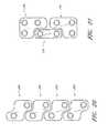
- an integrated fixation plate and spacer systemis provided, comprising two or more integrated fixation plate and spacer implants, wherein the fixation plates of each implant has a complementary configuration to allow attachment of the implants at adjacent intervertebral spaces.
- Alternative fixation systemsare also contemplated.
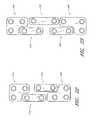
- an intervertebral stabilization systemcomprising a first stabilization plate integrated with a first spacer, wherein the first stabilization plate has an upper portion and a lower portion and a second stabilization plate integrated with a second spacer, wherein the second stabilization plate has an upper portion and a lower portion, wherein the lower portion of the first stabilization plate has a configuration complementary to the configuration of the upper portion of the second stabilization plate.
- the configuration of the lower portion of the second stabilization plateis complementary to the configuration of the upper portion of the second stabilization plate.
- the lower portion of the second stabilization platehas a relative shape equal to the relative shape of the upper portion of the second stabilization plate rotated 180 degrees.
- the upper portion of the first stabilization platemay comprise two attachment holes and the lower portion of the first stabilization plate may comprise one attachment hole.
- the intervertebral stabilization systemmay further comprise a third stabilization plate and a third spacer, wherein the configuration of the upper portion of the third stabilization plate is complementary to the configuration of the lower portion of the second stabilization plate.
- the third stabilization platemay be integrated with the third spacer.
- the lower portion of the third stabilization platemay have a configuration complementary to the configuration of the upper portion of the third stabilization plate.
- the lower portion of the third stabilization platemay have a relative shape equal to the relative shape of the upper portion of the third stabilization plate rotated 180 degrees.
- the intervertebral stabilization systemmay also further comprise a fourth stabilization plate and a fourth spacer, wherein the upper portion of the fourth stabilization plate has a configuration complementary to configuration of the lower portion of the third stabilization plate.
- the second stabilization plate and third stabilization platemay have the same configuration.
- the lower portion of the second stabilization platemay have a relative shape equal to the relative shape of the upper portion of the second stabilization plate rotated 180 degrees.
- the lower portion of the first stabilization platehas a right-sided complementary shape and the upper portion of the second stabilization plate has a left-sided complementary shape.
- the lower portion of the first stabilization platehas a left-sided complementary shape and the upper portion of the second stabilization plate has a right-sided complementary shape.
- the lower portion of the second stabilization platemay have a right-sided complementary shape.
- the lower portion of the second stabilization platemay have a left-sided complementary shape.
- the lower portion of the first stabilization platemay have an inside complementary shape and the upper portion of the second stabilization plate has an outside complementary shape.
- the lower portion of the first stabilization platemay have an underside complementary shape and the upper portion of the second stabilization plate has a topside complementary shape.
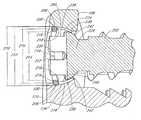
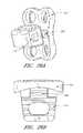
- an implant for treating the spinecomprising a stabilization plate having an access surface and a bone facing surface, an upper portion and a lower portion, a spacer integrated with the stabilization plate at the bone facing surface, a first attachment lumen between the access surface and the bone facing surface of the stabilization plate, the lumen having a first attachment diameter adjacent to the access surface of the stabilization plate, a lumen surface and a second attachment diameter adjacent to the bone facing surface of the stabilization plate, a retaining channel along the lumen surface, and a third attachment diameter about the retaining channel, wherein the first attachment diameter is greater than the second attachment diameter, a deformable retaining ring at least partially located within the retaining channel, and a first attachment lumen insert having an inner insert diameter and an outer insert diameter.
- the at least a portion of the spacermay comprise tissue engagement structures.
- the tissue engagement structuresmay comprise teeth.
- the implantmay further comprise a bone screw, the bone screw having a screw head and a screw body, wherein the screw head has a head diameter less than the first attachment diameter and greater than the second attachment diameter, or a head diameter less than the first attachment diameter and greater than the inner insert diameter.
- the implantmay further comprise a second attachment lumen between the access surface and the bone facing surface of the stabilization plate, the lumen having a fourth attachment diameter adjacent to the access surface of the stabilization plate, a lumen surface and a fifth attachment diameter adjacent to the bone facing surface of the stabilization plate.
- a method for treating a spinecomprising the steps of providing a first stabilization plate integrated with a first spacer, wherein the first stabilization plate comprises an upper portion, a lower portion and a plurality of attachment holes, at least one attachment hole comprising a retaining structure and an attachment insert, inserting the spacer component into a vertebral space between a first vertebra and a second vertebra, attaching the upper portion of the first stabilization plate to the first vertebra, and attaching the lower portion of the first stabilization plate to the second vertebra.
- a method for treating a spinecomprising the steps of providing an integrated stabilization plate and spacer system, comprising a first integrated stabilization plate and first spacer and a second integrated stabilization plate and a second spacer, each stabilization plate having an upper portion and a lower portion and wherein the lower portion of the first integrated stabilization plate has a complementary shape to the upper portion of the second integrated stabilization plate, inserting the first spacer into a first intervertebral space between a first vertebra and a second vertebra, attaching the upper portion of the first integrated stabilization plate to the first vertebra, attaching the lower portion of the first integrated stabilization plate to the second vertebra, inserting the second spacer into a second intervertebral space between the second vertebra and a third vertebra, wherein the second intervertebral space is next to the first intervertebral space along a vertebral column, attaching the upper portion of the second integrated stabilization plate to the second vertebra; and attaching the lower portion of the second integrated stabilization plate
- the integrated stabilization plate and spacer system of the providing stepmay further comprise a third integrated stabilization plate and a second spacer, wherein the lower portion of the second integrated stabilization plate has a complementary shape to the upper portion of the third integrated stabilization plate.
- the method for treating a spinemay further comprise the steps of inserting the third spacer into a third intervertebral space between the third vertebra and a fourth vertebra, wherein the third intervertebral space is next to the second intervertebral space along the vertebral column, attaching the upper portion of the third integrated stabilization plate to the third vertebra, and attaching the lower portion of the third integrated stabilization plate to the fourth vertebra.
- an orthopedic implant assemblycomprising a stabilizing element having a trailing surface, a leading surface and at least one lumen, the lumen having a first opening at the trailing surface, a second opening at the leading surface that is smaller than the first opening, and a passageway extending from the first opening to the second opening, a securing element having an elongated body, a head at one end of the body and integral therewith, and a lumen insert member defining a portion of the passageway, having an inner diameter and an outer diameter, and adapted to substantially reduce any force exerted between the stabilizing element and the securing element, wherein the diameter of the head of the securing element is greater than the lesser diameter between the second opening of the lumen and the inner diameter of the insert.
- the orthopedic implantmay further comprise an interbody element integral with the leading surface of the stabilizing element and/or a locking assembly for resisting movement of securing element in at least one direction.
- an implant for treating the spinecomprising: a fixation plate having an access surface and a bone facing surface, an upper portion and a lower portion; a spacer; and a moveable connection between the spacer and the bone facing surface of the fixation plate.
- the moveable connectionmay be a hinge joint, a ball and socket joint, or a metal cord attached between the spacer and the bone facing surface of the fixation plate.
- an implant for treating the spinecomprising: a fixation plate having an access surface and a bone facing surface, an upper portion and a lower portion; a spacer connected to the bone facing surface of the fixation plate; and one or more locking plates with an alignment structure to non-frictionally resist rotation of the locking plate when partially attached to the fixation plate by a fastener.
- an implant for treating the spinecomprising: a fixation plate having an access surface and a bone facing surface, an upper portion and a lower portion; a spacer connected to the fixation plate at the bone facing surface; a first attachment lumen between the access surface and the bone facing surface of the stabilization plate, the lumen having a first attachment diameter adjacent to the access surface of the stabilization plate, a lumen surface and a second attachment diameter adjacent to the bone facing surface of the stabilization plate, a retaining channel along the lumen surface, and a third attachment diameter about the retaining channel, wherein the first attachment diameter is greater than the second attachment diameter; and a deformable retaining ring having a retaining segment and a polyaxial segment and an abutting surface therebetween, wherein the retaining segment of the deformable retaining ring is at least partially located within the retaining channel.
- a system for attaching to a structurecomprising: an attachment device having an access surface, an facing surface, a first attachment lumen between the access surface and the facing surface of the attachment device, the first attachment lumen having a first attachment diameter adjacent to the access surface of the attachment device, a first lumen surface and a second attachment diameter adjacent to the facing surface of the attachment device, a first retaining channel along the first lumen surface, and a third attachment diameter about the first retaining channel, wherein the first attachment diameter is greater than the second attachment diameter; and a side-biased blocking structure at least partially within the retaining channel having an uncompressed configuration that protrudes into the first attachment lumen and a compressed configuration that does not protrude into the first attachment lumen.
- the blocking structuremay comprise a sloped surface.
- a fastenercomprising: a fastener head and fastener shaft, the fastener head comprising a screw lumen, an external groove and one or more openings between the screw lumen and external groove, and an expandable member located at least partially in the external groove and protruding through the one or more openings into the screw lumen.
- the expandable membermay be a ring.
- the fastenermay further comprise a secondary screw configured for the screw lumen.
- an intervertebral stabilization systemcomprising a first stabilization plate integrated with a first spacer, wherein the first stabilization plate comprises an upper portion and a lower portion, and a second stabilization plate integrated with a second spacer, wherein the second stabilization plate comprises an upper portion and a lower portion, wherein the lower portion of the first stabilization plate has a configuration complementary to the configuration of the upper portion of the second stabilization plate.
- the configuration of the lower portion of the second stabilization platemay be complementary to the configuration of the upper portion of the second stabilization plate.
- the lower portion of the second stabilization platemay have a relative shape equal to the relative shape of the upper portion of the second stabilization plate rotated 180 degrees.
- the upper portion of the first stabilization platemay comprise two attachment holes.
- the lower portion of the first stabilization platemay comprise one attachment hole.
- the intervertebral stabilization systemmay further comprise a third stabilization plate and a third spacer, wherein the configuration of the upper portion of the third stabilization plate may be complementary to the configuration of the lower portion of the second stabilization plate.
- the third stabilization platemay be integrated with the third spacer.
- the lower portion of the third stabilization platemay have a configuration complementary to the configuration of the upper portion of the third stabilization plate.
- the lower portion of the third stabilization platemay have a relative shape equal to the relative shape of the upper portion of the third stabilization plate rotated 180 degrees.
- the intervertebral stabilization systemmay further comprise a fourth stabilization plate and a fourth spacer, wherein the upper portion of the fourth stabilization plate has a configuration complementary to configuration of the lower portion of the third stabilization plate.
- the second stabilization plate and third stabilization platemay have the same configuration.
- the lower portion of the second stabilization platemay have a relative shape equal to the relative shape of the upper portion of the second stabilization plate rotated 180 degrees.
- the lower portion of the first stabilization platemay have a right-sided complementary shape and the upper portion of the second stabilization plate may have a left-sided complementary shape.
- the lower portion of the first stabilization platemay have a left-sided complementary shape and the upper portion of the second stabilization plate may have a right-sided complementary shape.
- the lower portion of the second stabilization platemay have a right-sided complementary shape.
- the lower portion of the second stabilization platemay have a left-sided complementary shape.
- the lower portion of the first stabilization platemay have an inside complementary shape and the upper portion of the second stabilization plate may have an outside complementary shape.
- the lower portion of the first stabilization platemay have an underside complementary shape and the upper portion of the second stabilization plate may have a topside complementary shape.
- an orthopedic implant assemblycomprising a stabilizing element having a trailing surface, a leading surface and at least one lumen, the lumen having a first opening at the trailing surface, a second opening at the leading surface that may be smaller than the first opening, and a passageway extending from the first opening to the second opening, a securing element having an elongated body, a head at one end of the body and integral therewith, and a lumen insert member within a portion of the passageway, the lumen insert member comprising an inner diameter and an outer diameter, and adapted to substantially reduce any force exerted between the stabilizing element and the securing element, wherein the diameter of the head of the securing element may be greater than the lesser diameter between the second opening of the lumen and the inner diameter of the insert.
- the orthopedic implant assemblymay further comprise an interbody element integral with the leading surface of the stabilizing element.
- the orthopedic implant assemblymay further comprise a locking assembly for resisting movement of securing element in at least one direction.
- a method for treating a spinecomprising providing an integrated stabilization plate and spacer system, comprising a first integrated stabilization plate and first spacer and a second integrated stabilization plate and a second spacer, wherein each stabilization plate having an upper portion and a lower portion and wherein the lower portion of the first integrated stabilization plate may have a complementary shape to the upper portion of the second integrated stabilization plate, inserting the first spacer into a first intervertebral space between a first vertebra and a second vertebra, attaching the upper portion of the first integrated stabilization plate to the first vertebra, attaching the lower portion of the first integrated stabilization plate to the second vertebra, inserting the second spacer into a second intervertebral space between the second vertebra and a third vertebra, wherein the second intervertebral space may be next to the first intervertebral space along a vertebral column, attaching the upper portion of the second integrated stabilization plate to the second vertebra, and attaching the lower portion of the second integrated stabilization
- the integrated stabilization plate and spacer system wherein providing the integrated stabilization plate and spacer systemmay further comprise a third integrated stabilization plate and a second spacer, wherein the lower portion of the second integrated stabilization plate may have a complementary shape to the upper portion of the third integrated stabilization plate.
- the method for treating a spinemay further comprise inserting the third spacer into a third intervertebral space between the third vertebra and a fourth vertebra, wherein the third intervertebral space may be next to the second intervertebral space along the vertebral column, attaching the upper portion of the third integrated stabilization plate to the third vertebra, and attaching the lower portion of the third integrated stabilization plate to the fourth vertebra.
- an implant for treating the spinecomprising, a stabilization plate comprising an access surface and a bone facing surface, an upper portion and a lower portion, a spacer integral with the stabilization plate at the bone facing surface, a first attachment lumen between the access surface and the bone facing surface of the stabilization plate, the first attachment lumen having a first attachment diameter adjacent to the access surface of the stabilization plate, a lumen surface and a second attachment diameter adjacent to the bone facing surface of the stabilization plate, a retaining channel along the lumen surface, and a third attachment diameter about the retaining channel, wherein the first attachment diameter may be greater than the second attachment diameter, a deformable retaining ring at least partially located within the retaining channel, and a first attachment lumen insert located at least partially in the first attachment lumen and having an inner insert diameter and an outer insert diameter.
- the spacermay comprise tissue engagement structures.
- the tissue engagement structuresmay comprise teeth.
- the implantmay further comprise a bone screw, the bone screw having a screw head and a screw body, wherein the screw head may have a head diameter less than the first attachment diameter and greater than the second attachment diameter.
- the implantmay further comprise a bone screw, the bone screw having a screw head and a screw body, wherein the screw head may have a head diameter less than the first attachment diameter and greater than the inner insert diameter.
- the outer insert diametermay be greater than the second attachment diameter and the inner insert diameter may be smaller than the second attachment diameter.
- the second attachment diameter and the third attachment diameterare generally equal.
- the first attachment lumen insertmay be located within the first attachment lumen.
- the first attachment lumen insertmay comprise an inner concave surface.
- the screw head of the bone screwmay comprise an outer convex surface.
- the outer convex surface of the screw headmay be complementary to the inner concave surface of the first attachment lumen insert.
- the implantmay further comprise a second attachment lumen between the access surface and the bone facing surface of the stabilization plate, the second attachment lumen having a fourth attachment diameter adjacent to the access surface of the stabilization plate, a lumen surface and a fifth attachment diameter adjacent to the bone facing surface of the stabilization plate.
- a method for treating a spinecomprising providing a first stabilization plate integral with a first spacer, wherein the first stabilization plate comprises an upper portion, a lower portion and a plurality of attachment holes, wherein at least one attachment hole comprising a retaining structure and an attachment insert, inserting the first spacer into a vertebral space between a first vertebra and a second vertebra, attaching the upper portion of the first stabilization plate to the first vertebra, and attaching the lower portion of the first stabilization plate to the second vertebra.
- the at least one attachment holemay further comprise a retaining groove and the retaining structure may be a retaining ring positioned in the retaining groove.
- the attachment insertmay comprise a concave surface.
- the retaining ringmay be integral with the attachment insert.
- Attaching the upper portion of the first stabilization plate to the first vertebramay comprise inserting a bone fastener through one of the plurality of attachment holes located in the upper portion of the first stabilization plate and engaging the first vertebra with the bone fastener.
- the methodmay further comprise providing a second stabilization plate integral with a second spacer, wherein the second stabilization plate may comprise an upper portion and a lower portion.
- the lower portion of the first stabilization platemay have a complementary configuration to the upper portion of the second stabilization plate.
- the methodmay further comprise inserting the second spacer into a vertebral space between the second vertebra and a third vertebra.
- an implant for treating the spinecomprising a fixation plate comprising an access surface and a bone facing surface, an upper portion and a lower portion, a spacer connected to the fixation plate at the bone facing surface, a first attachment lumen between the access surface and the bone facing surface of the stabilization plate, the lumen having a first attachment diameter adjacent to the access surface of the stabilization plate, a lumen surface and a second attachment diameter adjacent to the bone facing surface of the stabilization plate, a retaining channel along the lumen surface, and a third attachment diameter about the retaining channel, wherein the first attachment diameter may be greater than the second attachment diameter, a deformable retaining ring having a retaining segment and a polyaxial segment and an abutting surface therebetween, wherein the retaining segment of the deformable retaining ring may be at least partially located within the retaining channel.
- an implant for treating the spinecomprising a fixation plate having an access surface and a bone facing surface, an upper portion and a lower portion, a spacer, and a non-detachable articulation between the spacer and the bone facing surface of the fixation plate.
- the non-detachable articulationmay be a hinge joint.
- the hinge jointmay have a joint axis that does not intersect the fixation plate.
- the hinge jointmay have a joint axis configured to be generally perpendicular to a longitudinal axis of a vertebral column when implanted.
- the hinge jointmay have a joint axis configured to be generally parallel to a longitudinal axis of a vertebral column when implanted.
- the non-detachable articulationmay be a ball and socket joint.
- the non-detachable articulationmay comprise a metal cord attached between the spacer and the bone facing surface of the fixation plate.
- the non-detachable articulationmay be a pivoting articulation.
- an implant for treating the spinecomprising a fixation plate having an access surface and a bone facing surface, an upper portion and a lower portion, a spacer, and a pivoting articulation between the spacer and the bone facing surface of the fixation plate.
- the pivoting articulationmay be a hinge joint.
- the hinge jointmay have a joint axis configured to be generally perpendicular to a longitudinal axis of a vertebral column when implanted.
- the hinge jointmay have a joint axis configured to be generally parallel to a longitudinal axis of a vertebral column when implanted.
- the pivoting articulationmay be a ball and socket joint.
- the pivoting articulationmay comprise a metal cord attached between the spacer and the bone facing surface of the fixation plate.
- the pivoting articulationmay be a detachable articulation.
- an implant for treating the spinecomprising a fixation plate having an access surface and a bone facing surface, an upper portion and a lower portion, a spacer, and a rotatable articulation between the spacer and the fixation plate and comprising an axis of rotation, wherein the axis of rotation of the rotatable articulation does not intersect the fixation plate.
- the axis of rotation of the rotatable articulationmay be generally parallel to the fixation plate.
- the rotatable articulationmay be configured to allow reversible separation of the fixation plate and spacer.
- an implant for treating the spinecomprising a fixation plate comprising an access surface and a bone facing surface, an upper portion, a lower portion, and at least one attachment lumen between the access surface and the bone facing surface, a spacer connected to the bone facing surface of the fixation plate, and a locking plate configured to overlie the at least one attachment lumen and comprising an alignment structure to non-frictionally resist rotation of the locking plate when the locking plate is partially attached to the fixation plate by a fastener.
- the implantmay further comprise two attachment lumens and the locking plate may overlie at least one of the two attachment lumens.
- the locking platemay overlie both of the two attachment lumens.
- the fixation platemay further comprise a third attachment lumen.
- the locking platemay overlie the two attachment lumens and the third attachment lumen.
- the fixation platemay further comprise a fourth attachment lumen.
- the locking platemay overlie the two attachment lumens, the third attachment lumen and the fourth attachment lumen.
- At least a portion of the spacermay comprise tissue engagement structures.
- the tissue engagement structuresmay comprise teeth.
- the spacermay be integral with the bone facing surface of the fixation plate or may be connected to the bone facing surface of the fixation plate by an articulation joint.
- the articulation jointmay be separable or non-separable.
- the lower portion of the fixation platemay have a configuration complementary to the configuration of the upper portion of the fixation plate.
- the alignment structuremay comprise an elongate member and wherein the fixation plate may further comprise an alignment lumen configured to accept the elongate member.
- the elongate member and the alignment lumenmay be configured to resist rotation of the elongate member when in the alignment lumen.
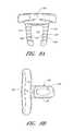
- the locking platemay have an X-shaped configuration or an H-shaped configuration.
- the locking platemay further comprise a second alignment structure and wherein the fixation plate may further comprise a second alignment lumen configured for accepting the second alignment structure.
- the locking platemay overlie one of the two attachment lumens and the implant may further comprise a second locking plate overlying the other of the two attachment lumens.
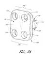
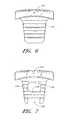
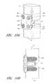
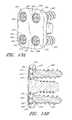
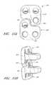
- an implant for treating the spinecomprising a flanged intervertebral spacer comprising a spacer body and a flange section, the flange section comprising an access surface and a bone facing surface, an upper portion, a lower portion, four attachment lumens between the access surface and the bone facing surface and two alignment lumens, a locking plate comprising four attachment cover sections and two alignment pins, wherein the four attachment cover sections are configured to cover the four attachment lumens of the flange section and the two alignment pins are configured for insertion into the two alignment lumens of the flange section.
- a system for attaching to a structurecomprising an attachment device having an access surface, a facing surface, a first attachment lumen between the access surface and the facing surface of the attachment device, the first attachment lumen having a first attachment diameter adjacent to the access surface of the attachment device, a first lumen surface and a second attachment diameter adjacent to the facing surface of the attachment device, a first retaining channel along the first lumen surface, and a third attachment diameter about the first retaining channel, wherein the first attachment diameter may be greater than the second attachment diameter, and a side-biased blocking structure at least partially within the retaining channel and comprising an uncompressed configuration that protrudes into the first attachment lumen and a compressed configuration that does not protrude into the first attachment lumen.
- the blocking structuremay comprise a slope surface.
- the blocking structuremay be an arcuate structure.
- the arcuate structuremay be a ring structure.
- the blocking structuremay be a rectangular plate with a through lumen.
- the through lumenmay be a circular through lumen.
- the attachment structuremay be an interbody spacer, a flanged interbody spacer, a fixation plate a vertebral fixation plate, or an anterior cervical fixation plate.
- the blocking structuremay comprise a helical spring member, a leaf spring member, or an elongate bias member.
- the blocking structuremay comprise a second elongate bias member.
- the elongate bias membermay have an arcuate shape.
- a method for treating the spinecomprising providing an orthopedic device comprising a fastener lumen, a securing structure space about the fastener lumen, a securing structure in the fastener lumen and the securing structure space, wherein the securing structure may comprise a bias element and a non-deformable blocking element, inserting a fastener into the fastener lumen, displacing at least a portion of the non-deformable blocking element from the fastener lumen into the securing structure space by compressing the bias element, and passing the head of the fastener past the non-deformable blocking element to allow re-expansion of the bias element.
- a method for treating the spinecomprising providing an orthopedic device comprising a fastener lumen with a longitudinal lumen axis, a securing structure space about the fastener lumen, a securing structure in the fastener lumen and the securing structure space, wherein the securing structure may comprise a biased lumen blocker, inserting a fastener into the fastener lumen, eccentrically displacing the biased lumen blocker with respect to the longitudinal axis of the fastener lumen, and passing the fastener past biased lumen blocker to allow reversion of the biased lumen blocker toward a prior position.
- the methodmay further comprise reverting the biased lumen blocker toward a prior position or to a prior position.
- a fastenercomprising a fastener head and fastener shaft, the fastener head comprising a screw lumen, an external groove and one or more openings between the screw lumen and external groove, and an expandable member located at least partially in the external groove and protruding through the one or more openings into the screw lumen.
- the expandable membermay be a ring.
- the fastenermay further comprise a secondary screw configured for the screw lumen.
- an orthopedic fastening systemcomprising a fastener comprising a fastener head and a threaded fastener body, wherein the fastener head may comprise a lumen opening, a central internal lumen contiguous with the lumen opening, a side lumen contiguous with the central internal lumen and an expansion member located at least partially within the side lumen and having an expanded configuration and a reduced configuration.
- the fastener headmay further comprise an internal screw and located in the central internal lumen, the internal screw having a proximal position and a distal position. The internal screw in the proximal position may be located about the side lumen and in the distal position may be located distal to the side lumen.
- the proximal position of the internal screwmay displace the expansion member into the expanded configuration.
- the orthopedic proximal position of the internal screwat least partially displaces the expansion member out of the side lumen.
- the proximal position of the internal screwallows the expansion member to be in the reduced configuration.
- the expansion member in the reduced configurationmay be partially located in the central internal lumen.
- the proximal position of the internal screwat least partially displaces the expansion member out of the central internal lumen.
- the fastener headmay further comprise an expansion groove contiguous with the side lumen and the expansion member may comprise an elongate body positioned about the expansion groove.
- the elongate bodymay be an arcuate elongate body.
- the expansion membermay further comprise a radial elongate body located at least partially in the side lumen.
- the orthopedic fastening systemmay further comprise an orthopedic device comprising a fastener lumen adapted to retain the fastener.
- the fastener lumenmay comprise a proximal diameter, a middle diameter and a distal diameter, wherein the proximal diameter is smaller than the middle diameter.
- the distal diameter of the fastener lumenmay be smaller than the proximal diameter of the fastener lumen.
- the fastener lumenmay comprises a hole insert.
- the hole insertmay comprise a proximal diameter, a middle diameter and a distal diameter, wherein the proximal diameter is smaller than the middle diameter.
- the orthopedic devicemay be an interbody spacer, a flanged interbody spacer, a fixation plate, a vertebral fixation plate, or an anterior cervical fixation plate.
- a method for securing an orthopedic device to a bonecomprising providing an orthopedic device comprising a fastener lumen and a fastener, the fastener comprising a fastener head and a fastener body, the fastener head comprising a lumen opening, a central internal lumen contiguous with the lumen opening, an internal screw located within the central internal lumen, a side lumen contiguous with the central internal lumen and an expansion member located at least partially within the side lumen and the central internal lumen and having an expanded configuration and a reduced configuration, attaching the orthopedic device to a bone in a body, moving the internal screw to a position about the side lumen, partially displacing the expansion member with respect to the side lumen, and changing the expansion member to its expanded configuration.
- the fastener lumenmay comprise a middle diameter and a proximal diameter, where the proximal diameter may be less than the middle diameter.
- the reduced configuration of the expansion membermay have a diameter less than the proximal diameter and the expanded configuration of the expansion member may have a diameter between the proximal diameter and the middle diameter.
- Attaching the orthopedic device to a bone in a bodymay comprise inserting the fastener into the fastener lumen, and inserting the fastener into the bone of the body.
- the orthopedic devicemay be an interbody spacer.
- the interbody spacermay be a flanged interbody spacer, a fixation plate, a vertebral fixation plate, or an anterior cervical fixation plate.
- a method for securing a device to an objectcomprising providing a device comprising a fastener lumen and a fastener, the fastener comprising a fastener head and a fastener body, the fastener head comprising a lumen opening, a central internal lumen contiguous with the lumen opening, an internal screw located within the central internal lumen, a side lumen contiguous with the central internal lumen and an expansion member located at least partially within the side lumen and the central internal lumen and having an expanded configuration and a reduced configuration, attaching the device to an object, moving the internal screw to a position about the side lumen, partially displacing the expansion member with respect to the side lumen, and changing the expansion member to its expanded configuration.
- the fastener lumenmay comprise a middle diameter and a proximal diameter, where the proximal diameter may be less than the middle diameter.
- the reduced configuration of the expansion membermay have a diameter less than the proximal diameter and the expanded configuration of the expansion member may have a diameter between the proximal diameter and the middle diameter.
- Attaching the device to the objectmay comprise inserting the fastener into the fastener lumen, and inserting the fastener into the object.
- an intervertebral stabilization systemcomprising a first stabilization plate integrated with a first spacer, wherein the first stabilization plate may comprise an upper portion and a lower portion, and a second stabilization plate integrated with a second spacer, wherein the second stabilization plate may comprise an upper portion and a lower portion, wherein the lower portion of the first stabilization plate may have a configuration complementary to the configuration of the upper portion of the second stabilization plate.
- the configuration of the lower portion of the second stabilization platemay be complementary to the configuration of the upper portion of the second stabilization plate, or may have a relative shape equal to the relative shape of the upper portion of the second stabilization plate rotated 180 degrees.
- the upper portion of the first stabilization platemay comprise two attachment holes.
- the lower portion of the first stabilization platemay comprise one attachment hole.
- the intervertebral stabilization systemmay further comprise a third stabilization plate and a third spacer, wherein the configuration of the upper portion of the third stabilization plate may be complementary to the configuration of the lower portion of the second stabilization plate.
- the third stabilization platemay be integrated with the third spacer.
- the lower portion of the third stabilization platemay have a configuration complementary to the configuration of the upper portion of the third stabilization plate, or may have a relative shape equal to the relative shape of the upper portion of the third stabilization plate rotated 180 degrees.
- the intervertebral stabilization systemmay further comprise a fourth stabilization plate and a fourth spacer, wherein the upper portion of the fourth stabilization plate may have a configuration complementary to configuration of the lower portion of the third stabilization plate.
- the second stabilization plate and third stabilization platehave the same configuration.
- the lower portion of the second stabilization platemay have a relative shape equal to the relative shape of the upper portion of the second stabilization plate rotated 180 degrees.
- the lower portion of the first stabilization platemay have a right-sided complementary shape and the upper portion of the second stabilization plate may have a left-sided complementary shape.
- the lower portion of the first stabilization platemay have a left-sided complementary shape and the upper portion of the second stabilization plate may have a right-sided complementary shape.
- the lower portion of the second stabilization platemay have a right-sided complementary shape.
- the lower portion of the second stabilization platemay have a left-sided complementary shape.
- the lower portion of the first stabilization platemay have an inside complementary shape and the upper portion of the second stabilization plate may have an outside complementary shape.
- the lower portion of the first stabilization platemay have an underside complementary shape and the upper portion of the second stabilization plate may have a topside complementary shape.
- an orthopedic implant assemblycomprising a stabilizing element having a trailing surface, a leading surface and at least one lumen, the lumen having a first opening at the trailing surface, a second opening at the leading surface that may be smaller than the first opening, and a passageway extending from the first opening to the second opening, a securing element having an elongated body, a head at one end of the body and integral therewith, and a lumen insert member within a portion of the passageway, the lumen insert member having an inner diameter and an outer diameter, and adapted to substantially reduce any force exerted between the stabilizing element and the securing element, wherein the diameter of the head of the securing element may be greater than the lesser diameter between the second opening of the lumen and the inner diameter of the insert.
- the orthopedic implant assemblymay further comprise an interbody element integral with the leading surface of the stabilizing element.
- the orthopedic implant assemblymay further comprise a locking assembly for resisting movement of securing element in at least one direction.
- a method for treating a spinecomprising providing an integrated stabilization plate and spacer system, the integrated stabilization plate and spacer system comprising a first integrated stabilization plate and first spacer and a second integrated stabilization plate and a second spacer, wherein each stabilization plate has an upper portion and a lower portion and wherein the lower portion of the first integrated stabilization plate has a complementary shape to the upper portion of the second integrated stabilization plate, inserting the first spacer into a first intervertebral space between a first vertebra and a second vertebra, attaching the upper portion of the first integrated stabilization plate to the first vertebra, attaching the lower portion of the first integrated stabilization plate to the second vertebra, inserting the second spacer into a second intervertebral space between the second vertebra and a third vertebra, wherein the second intervertebral space is next to the first intervertebral space along a vertebral column, attaching the upper portion of the second integrated stabilization plate to the second vertebra, and attaching the lower
- Providing the integrated stabilization plate and spacer systemfurther may comprise a third integrated stabilization plate and a second spacer, wherein the lower portion of the second integrated stabilization plate may have a complementary shape to the upper portion of the third integrated stabilization plate.
- the method for treating a spinemay further comprise the steps of inserting the third spacer into a third intervertebral space between the third vertebra and a fourth vertebra, wherein the third intervertebral space is next to the second intervertebral space along the vertebral column, attaching the upper portion of the third integrated stabilization plate to the third vertebra, and attaching the lower portion of the third integrated stabilization plate to the fourth vertebra.
- an implant for treating the spinecomprising a stabilization plate comprising an access surface and a bone facing surface, an upper portion and a lower portion, a spacer integral with the stabilization plate at the bone facing surface, a first attachment lumen between the access surface and the bone facing surface of the stabilization plate, the first attachment lumen having a first attachment diameter adjacent to the access surface of the stabilization plate, a lumen surface and a second attachment diameter adjacent to the bone facing surface of the stabilization plate, a retaining channel along the lumen surface, and a third attachment diameter about the retaining channel, wherein the first attachment diameter may be greater than the second attachment diameter, a deformable retaining ring at least partially located within the retaining channel, and a first attachment lumen insert located at least partially in the first attachment lumen and having an inner insert diameter and an outer insert diameter.
- the spacermay comprise tissue engagement structures.
- the tissue engagement structuresmay comprise teeth.
- the implant for treating the spinemay further comprise a bone screw, the bone screw having a screw head and a screw body, wherein the screw head has a head diameter less than the first attachment diameter and greater than the second attachment diameter.
- the implant for treating the spinemay further comprise a bone screw, the bone screw having a screw head and a screw body, wherein the screw head may have a head diameter less than the first attachment diameter and greater than the inner insert diameter.
- the outer insert diametermay be greater than the second attachment diameter and the inner insert diameter may be smaller than the second attachment diameter.
- the second attachment diameter and the third attachment diametermay be generally equal.
- the first attachment lumen insertmay be located within the first attachment lumen.
- the first attachment lumen insertmay comprise an inner concave surface.
- the screw head of the bone screwmay comprise an outer convex surface.
- the outer convex surface of the screw headmay be complementary to the inner concave surface of the first attachment lumen insert.
- the implant for treating the spinemay further comprise a second attachment lumen between the access surface and the bone facing surface of the stabilization plate, the lumen having a fourth attachment diameter adjacent to the access surface of the stabilization plate, a lumen surface and a fifth attachment diameter adjacent to the bone facing surface of the stabilization plate.
- a method for treating a spinecomprising providing a first stabilization plate integral with a first spacer, wherein the first stabilization plate may comprise an upper portion, a lower portion and a plurality of attachment holes, wherein at least one attachment hole comprises a retaining structure and an attachment insert, inserting the first spacer into a vertebral space between a first vertebra and a second vertebra, attaching the upper portion of the first stabilization plate to the first vertebra, and attaching the lower portion of the first stabilization plate to the second vertebra.
- the at least one attachment holefurther may comprise a retaining groove and the retaining structure may be a retaining ring positioned in the retaining groove.
- the attachment insertmay comprise a concave surface.
- the retaining ringmay be integral with the attachment insert.
- Attaching the upper portion of the first stabilization plate to the first vertebramay comprise inserting a bone fastener through one of the plurality of attachment holes located in the upper portion of the first stabilization plate and engaging the first vertebra with the bone fastener.
- the method for treating a spinemay further comprise providing a second stabilization plate integral with a second spacer, wherein the second stabilization plate may comprise an upper portion and a lower portion.
- the lower portion of the first stabilization platemay have a complementary configuration to the upper portion of the second stabilization plate.
- the method for treating a spinemay further comprise inserting the second spacer into a vertebral space between the second vertebra and a third vertebra.
- an implant for treating the spinecomprising a fixation plate comprising an access surface and a bone facing surface, an upper portion and a lower portion, a spacer connected to the fixation plate at the bone facing surface, a first attachment lumen between the access surface and the bone facing surface of the stabilization plate, the lumen having a first attachment diameter adjacent to the access surface of the stabilization plate, a lumen surface and a second attachment diameter adjacent to the bone facing surface of the stabilization plate, a retaining channel along the lumen surface, and a third attachment diameter about the retaining channel, wherein the first attachment diameter is greater than the second attachment diameter, a deformable retaining ring having a retaining segment and a polyaxial segment and an abutting surface therebetween, wherein the retaining segment of the deformable retaining ring is at least partially located within the retaining channel.
- an implant for treating the spinecomprising a fixation plate having an access surface and a bone facing surface, an upper portion and a lower portion, a spacer, and a non-detachable articulation between the spacer and the bone facing surface of the fixation plate.
- the non-detachable articulationmay be a hinge joint.
- the hinge jointmay have a joint axis that does not intersect the fixation plate.
- the hinge jointmay have a joint axis configured to be generally perpendicular to a longitudinal axis of a vertebral column when implanted.
- the hinge jointmay have a joint axis configured to be generally parallel to a longitudinal axis of a vertebral column when implanted.
- the non-detachable articulationmay be a ball and socket joint.
- the non-detachable articulationmay comprise a metal cord attached between the spacer and the bone facing surface of the fixation plate.
- the non-detachable articulationmay be a pivoting articulation.
- an implant for treating the spinecomprising a fixation plate having an access surface and a bone facing surface, an upper portion and a lower portion, a spacer, and a pivoting articulation between the spacer and the bone facing surface of the fixation plate.
- the pivoting articulationmay be a hinge joint.
- the hinge jointmay have a joint axis configured to be generally perpendicular to a longitudinal axis of a vertebral column when implanted.
- the hinge jointmay have a joint axis configured to be generally parallel to a longitudinal axis of a vertebral column when implanted.
- the pivoting articulationmay be a ball and socket joint.
- the pivoting articulationmay comprise a metal cord attached between the spacer and the bone facing surface of the fixation plate.
- the pivoting articulationmay be a detachable articulation.
- an implant for treating the spinecomprising a fixation plate having an access surface and a bone facing surface, an upper portion and a lower portion, a spacer, and a rotatable articulation between the spacer and the fixation plate and comprising an axis of rotation, wherein the axis of rotation of the rotatable articulation does not intersect the fixation plate.
- the axis of rotation of the rotatable articulationmay be generally parallel to the fixation plate.
- the rotatable articulationmay be configured to allow reversible separation of the fixation plate and spacer.
- an implant for treating the spinecomprising a fixation plate comprising an access surface and a bone facing surface, an upper portion, a lower portion, and at least one attachment lumen between the access surface and the bone facing surface, a spacer connected to the bone facing surface of the fixation plate, and a locking plate configured to overlie the at least one attachment lumen and comprising an alignment structure to non-frictionally resist rotation of the locking plate when the locking plate may be partially attached to the fixation plate by a fastener.
- the fixation platefurther may comprise two attachment lumens and the locking plate overlies at least one of the two attachment lumens. The locking plate may overlie both of the two attachment lumens.
- the fixation platefurther may comprise a third attachment lumen.
- the locking platemay overlie the two attachment lumens and the third attachment lumen.
- the fixation platefurther may comprise a fourth attachment lumen.
- the locking platemay overlie the two attachment lumens, the third attachment lumen and the fourth attachment lumen.
- At least a portion of the spacermay comprise tissue engagement structures.
- the tissue engagement structuresmay comprise teeth.
- the spacermay be integral with the bone facing surface of the fixation plate.
- the spacermay be connected to the bone facing surface of the fixation plate by an articulation joint.
- the articulation jointmay be separable or non-separable.
- the lower portion of the fixation platemay have a configuration complementary to the configuration of the upper portion of the fixation plate.
- the alignment structuremay comprise an elongate member and wherein the fixation plate further may comprise an alignment lumen configured to accept the elongate member.
- the elongate member and the alignment lumenmay be configured to resist rotation of the elongate member when in the alignment lumen.
- the locking platemay have an X-shaped configuration.
- the locking platemay have an H-shaped configuration.
- the locking platefurther may comprise a second alignment structure and wherein the fixation plate further may comprise a second alignment lumen configured for accepting the second alignment structure.
- the locking platemay overlie one of the two attachment lumens and the implant further may comprise a second locking plate overlying the other of the two attachment lumens.
- an implant for treating the spinecomprising a flanged intervertebral spacer comprising a spacer body and a flange section, the flange section comprising an access surface and a bone facing surface, an upper portion, a lower portion, four attachment lumens between the access surface and the bone facing surface and two alignment lumens, a locking plate comprising four attachment cover sections and two alignment pins, wherein the four attachment cover sections are configured to cover the four attachment lumens of the flange section and the two alignment pins are configured for insertion into the two alignment lumens of the flange section.
- a system for attaching to a structurecomprising an attachment device having an access surface, a facing surface, a first attachment lumen between the access surface and the facing surface of the attachment device, the first attachment lumen having a first attachment diameter adjacent to the access surface of the attachment device, a first lumen surface and a second attachment diameter adjacent to the facing surface of the attachment device, a first retaining channel along the first lumen surface, and a third attachment diameter about the first retaining channel, wherein the first attachment diameter may be greater than the second attachment diameter, and a side-biased blocking structure at least partially within the retaining channel having an uncompressed configuration that protrudes into the first attachment lumen and a compressed configuration that does not protrude into the first attachment lumen.
- the blocking structuremay comprise a slope surface.
- the blocking structuremay be an arcuate structure.
- the arcuate structuremay be a ring structure.
- the blocking structuremay be a rectangular plate with a through lumen.
- the through lumenmay be a circular through lumen.
- the attachment structuremay be an interbody spacer.
- the interbody spacermay be a flanged interbody spacer.
- the attachment structuremay be a fixation plate.
- the attachment structuremay be a vertebral fixation plate.
- the vertebral fixation platemay be an anterior cervical fixation plate.
- the blocking structuremay comprise a helical spring member.
- the blocking structuremay comprise a leaf spring member.
- the blocking structuremay comprise an elongate bias member.
- the blocking structuremay comprise a second elongate bias member.
- the elongate bias membermay have an arcuate shape.
- a method for treating the spinecomprising providing an orthopedic device comprising a fastener lumen, a securing structure space about the fastener lumen, a securing structure in the fastener lumen and the securing structure space, wherein the securing structure is a bias element and a non-deformable blocking element, inserting a fastener into the fastener lumen, displacing at least a portion of the non-deformable blocking element from the fastener lumen into the securing structure space by compressing the bias element, and passing the head of the fastener past the non-deformable blocking element to allow re-expansion of the bias element.
- a method for treating the spinecomprising providing an orthopedic device comprising a fastener lumen with a longitudinal lumen axis, a securing structure space about the fastener lumen, a securing structure in the fastener lumen and the securing structure space, wherein the securing structure may comprise a biased lumen blocker, inserting a fastener into the fastener lumen, eccentrically displacing the biased lumen blocker with respect to the longitudinal axis of the fastener lumen, and passing the fastener past biased lumen blocker to allow reversion of the biased lumen blocker toward a prior position.
- the method for treating the spinemay further comprise reverting the biased lumen blocker toward a prior position.
- the method for treating the spinemay further comprise reverting the biased lumen blocker to a prior position.
- a fastenercomprising a fastener head and fastener shaft, the fastener head comprising a screw lumen, an external groove and one or more openings between the screw lumen and external groove, and an expandable member located at least partially in the external groove and protruding through the one or more openings into the screw lumen.
- the expandable membermay be a ring.
- the fastenermay further comprise a secondary screw configured for the screw lumen.
- an orthopedic fastening systemcomprising a fastener comprising a fastener head and a threaded fastener body, wherein the fastener head may comprise a lumen opening, a central internal lumen contiguous with the lumen opening, a side lumen contiguous with the central internal lumen and an expansion member located at least partially within the side lumen and having an expanded configuration and a reduced configuration.
- the fastener headfurther may comprise an internal screw and located in the central internal lumen, the internal screw having a proximal position and a distal position. The internal screw in the proximal position may be located about the side lumen and in the distal position may be located distal to the side lumen.
- the proximal position of the internal screwmay displace the expansion member into the expanded configuration.
- the proximal position of the internal screwmay at least partially displace the expansion member out of the side lumen.
- the proximal position of the internal screwmay allow the expansion member to be in the reduced configuration.
- the expansion member in the reduced configurationmay be partially located in the central internal lumen.
- the proximal position of the internal screwat least partially displaces the expansion member out of the central internal lumen.
- the expansion membermay be biased to the reduced configuration.
- the fastener headfurther may comprise an expansion groove contiguous with the side lumen and the expansion member may comprise an elongate body positioned about the expansion groove.
- the elongate bodymay be an arcuate elongate body.
- the expansion memberfurther may comprise a radial elongate body located at least partially in the side lumen.
- the orthopedic fastening systemmay further comprise an orthopedic device comprising a fastener lumen adapted to retain the fastener.
- the fastener lumenmay comprise a proximal diameter, a middle diameter and a distal diameter, wherein the proximal diameter may be smaller than the middle diameter.
- the distal diameter of the fastener lumenmay be smaller than the proximal diameter of the fastener lumen.
- the fastener lumenmay comprise a hole insert.
- the hole insertmay comprise a proximal diameter, a middle diameter and a distal diameter, wherein the proximal diameter may be smaller than the middle diameter.
- the orthopedic devicemay be an interbody spacer.
- the interbody spacermay be a flanged interbody spacer.
- the orthopedic devicemay be a fixation plate.
- the orthopedic devicemay be a vertebral fixation plate.
- a method for securing an orthopedic device to a bonecomprising providing an orthopedic device comprising a fastener lumen and a fastener, the fastener comprising a fastener head and a fastener body, the fastener head comprising a lumen opening, a central internal lumen contiguous with the lumen opening, an internal screw located within the central internal lumen, a side lumen contiguous with the central internal lumen and an expansion member located at least partially within the side lumen and the central internal lumen and having an expanded configuration and a reduced configuration, attaching the orthopedic device to a bone in a body, moving the internal screw to a position about the side lumen, partially displacing the expansion member with respect to the side lumen, and changing the expansion member to its expanded configuration.
- the fastener lumenmay comprise a middle diameter and a proximal diameter, where the proximal diameter may be less than the middle diameter.
- the reduced configuration of the expansion membermay have a diameter less than the proximal diameter and the expanded configuration of the expansion member may have a diameter between the proximal diameter and the middle diameter.
- Attaching the orthopedic device to a bone in a bodymay comprise inserting the fastener into the fastener lumen, and inserting the fastener into the bone of the body.
- the orthopedic devicemay be an interbody spacer.
- the interbody spacermay be a flanged interbody spacer.
- the orthopedic devicemay be a fixation plate.
- the orthopedic devicemay be a vertebral fixation plate.
- the vertebral fixation platemay be an anterior cervical fixation plate.
- a method for securing an device to an objectcomprising providing a device comprising a fastener lumen and a fastener, the fastener comprising a fastener head and a fastener body, the fastener head comprising a lumen opening, a central internal lumen contiguous with the lumen opening, an internal screw located within the central internal lumen, a side lumen contiguous with the central internal lumen and an expansion member located at least partially within the side lumen and the central internal lumen and having an expanded configuration and a reduced configuration, attaching the device to an object, moving the internal screw to a position about the side lumen, partially displacing the expansion member with respect to the side lumen, and changing the expansion member to its expanded configuration.
- the fastener lumenmay comprise a middle diameter and a proximal diameter, where the proximal diameter may be less than the middle diameter.
- the reduced configuration of the expansion membermay have a diameter less than the proximal diameter and the expanded configuration of the expansion member may have a diameter between the proximal diameter and the middle diameter.
- Attaching the device to the objectmay comprise inserting the fastener into the fastener lumen, and inserting the fastener into the object.
- FIG. 1is a lateral elevational view of a portion of the vertebral column.
- FIGS. 2A and 2Bare superior and lateral elevational views of a thoracic vertebra.
- FIG. 3illustrates a superior elevational view of a cervical vertebra.
- FIG. 4represents a superior elevational view of a lumbar vertebra.
- FIGS. 5A through 5Care perspective, superior and lateral elevational views of one embodiment of an integrated fixation plate and spacer.
- FIG. 6is a superior elevational view of another embodiment of an integrated fixation plate and spacer.
- FIG. 7is a superior elevational view of another embodiment of an integrated fixation plate and spacer.
- FIGS. 8A and 8Billustrate superior and lateral elevational views of another embodiment of an integrated fixation plate and spacer.
- FIGS. 9A and 9Billustrate superior and lateral elevational views of another embodiment of an integrated fixation plate and spacer.
- FIGS. 10A and 10Bare schematic perspective and lateral views of one embodiment of the invention attached to a vertebral column.
- FIGS. 10C and 10Dare schematic perspective and lateral views of another embodiment of the invention attached to a vertebral column with angled screws.
- FIG. 11depicts a cross sectional magnified view of one embodiment of a screw and a fixation plate hole.
- FIG. 12depicts a cross sectional magnified view of one embodiment of a screw and a polyaxial fixation plate hole.
- FIG. 13Ais a perspective view of one embodiment of the invention comprising a retaining ring and fixation hole insert.
- FIGS. 13B and 13Care cross sectional views of the device in FIG. 13A .
- FIG. 14is a cross sectional view of another embodiment of the invention comprising an angled retaining ring.
- FIGS. 15A and 15Bare frontal and perspective views of one embodiment of a complementary two spacer system.
- FIGS. 16A and 16Bare frontal and perspective views of one embodiment of a complementary three spacer system.
- FIGS. 17A and 17Bare frontal and perspective views of one embodiment of a complementary four spacer system.
- FIG. 18is a frontal view of one embodiment of the invention comprising a variable width spacer system.
- FIG. 19is a frontal view of one embodiment of the invention comprising a variable height spacer system.
- FIG. 20is a frontal view of one embodiment of a complementary identical four spacer system.
- FIG. 21is a frontal view of another embodiment of a complementary three spacer system.
- FIG. 22is a frontal view of another embodiment of a complementary four spacer system.
- FIG. 23is a frontal view of one embodiment of a complementary five spacer system.
- FIG. 24is a frontal view of another embodiment of a complementary four spacer system.
- FIGS. 25A and 25Brepresent frontal and lateral views of one embodiment comprising a complementary overlapping spacer system.
- FIGS. 26A to 26Dare various views of a pivotable interbody-plate device.
- FIG. 27is isometric elevational view of another embodiment of a fastener retaining assembly.
- FIG. 28is a cross-sectional view of a fixation device with the fastener retaining assembly of FIG. 27 and an inserted screw.
- FIG. 29Ais a cross-sectional view of another embodiment of a fastener with an expansion ring.
- FIG. 29Bis an exploded view of the fastener and expansion ring in FIG. 29A .
- FIGS. 30A and 30Bare superior oblique views of a fastener retaining body with side-bias members in uncompressed and compressed positions, respectively.
- FIG. 31is an oblique cut-away view of the fastener retaining body in FIG. 30A within a retaining body space about a fastener lumen.
- FIG. 32Ais a superior elevational of a fastener head positioned within a fastener lumen whereby the fastener has displaced the fastener retaining body into the compressed position.
- FIGS. 32B and 32Care superior side cross-sectional views of fastener head and fastener retaining body from FIG. 32A .
- FIG. 33Ais a superior elevational of a fastener head positioned within a fastener lumen whereby the fastener head has fully passed through the fastener retaining body and the fastener retaining body has reverted to its uncompressed configuration.
- FIGS. 33B and 33Care superior side cross-sectional views of fastener head and fastener retaining body from FIG. 33A .
- FIG. 34Ais an anterior elevational view of one embodiment of the invention comprising a locking plate and flanged interbody fusion device.
- FIG. 34Bdepicts the locking plate of FIG. 34A separated from the flanged interbody fusion device.
- FIGS. 35A and 35Bare oblique and anterior elevational views of another embodiment of the invention comprising dual locking plates.
- FIGS. 36A and 36Bare side and anterior elevational view of another embodiment of the invention comprising an angled locking plate.
- FIG. 37is a cross-sectional view of another embodiment of a fastener with an expansion ring.
- Spinal fusionis a procedure that involves joining two or more adjacent vertebrae so that they no longer are able to move relative to each other.
- an implanthaving a locking mechanism that can be easily and reliably locked in place to prevent the loosening of and backing out of the bone screws used to attach the implant to the vertebrae in the anterior aspect of the cervical, thoracic, and lumbar spine.
- Implants adapted for use in the lumbar spine and the thoracic spinebecome much less usable in the cervical spine because of differences in anatomy.
- the disc spacesare about 25% as tall as the vertebral bodies (i.e., the vertebral bodies are generally four times taller than the intervening disc space).
- the disc spacecan be 50% of the height of the vertebral bodies.
- the disc spaces in the cervical spineare generally not greater than 7 or 8 mm tall in most people.
- Attachment of one fixation plate between two vertebraeoften prevents the attachment of additional fixation plates between one of two vertebrae and an adjacent vertebra. This is especially true in the cervical spine region.
- the attachment of one fixation platewill reduce the surface area available to attach another fixation plate due to the small size of the cervical vertebrae and the minimum size required for each fixation plate. Because of this limitation in existing spinal fixation devices, treatment of spinal disorders may be suboptimal because disease in adjacent vertebrae cannot be treated adequately.
- the vertebral column 2comprises a series of alternating vertebrae 4 and fibrous discs 6 that provide axial support and movement to the upper portions of the body.
- the vertebral column 2typically comprises thirty-three vertebrae 4 , with seven cervical (C1-C7), twelve thoracic (T1-T12), five lumbar (L1-15), five fused sacral (S1-S5) and four fused coccygeal vertebrae.
- FIGS. 2A and 2Bdepict a typical thoracic vertebra.
- Each vertebraincludes an anterior body 8 with a posterior arch 10 .
- the posterior arch 10comprises two pedicles 12 and two laminae 14 that join posteriorly to form a spinous process 16 .
- a transverse 18 , superior 20 and inferior articular process 22Projecting from each side of the posterior arch 10 is a transverse 18 , superior 20 and inferior articular process 22 .
- the facets 24 , 26 of the superior 20 and inferior articular processes 22form facet joints 28 with the articular processes of the adjacent vertebrae.
- the typical cervical vertebrae 30differ from the other vertebrae with relatively larger spinal canals 32 , oval shaped vertebral bodies 34 , bifid spinous processes 36 and foramina 38 in their transverse processes 40 . These foramina transversaria 38 contain the vertebral artery and vein.
- the first and second cervical vertebraealso further differentiated from the other vertebrae.
- the first cervical vertebralacks a vertebral body and instead contains an anterior tubercle. Its superior articular facets articulate with the occipital condyles of the skull and are oriented in a roughly parasagittal plane. The cranium is able to slide forward and backwards on this vertebra.
- the second cervical vertebracontains an odontoid process, or dens, which projects superiorly from its body. It articulates with the anterior tubercle of the atlas, forming a pivot joint. Side to side movements of the head occur at this joint.
- the seventh cervical vertebrais sometimes considered atypical since it lacks a bifid spinous process.
- the typical lumbar vertebrae 42is distinguishable from the other vertebrae by the absence of foramina transversaria and the absence of facets on the surface of the vertebral body 44 .
- the lumbar vertebral bodies 44are larger than the thoracic vertebral bodies and have thicker pedicles 46 and laminae 48 projecting posteriorly.
- the vertebral foramen 50is triangular in shape and larger than the foramina in the thoracic spine but smaller than the foramina in the cervical spine.
- the superior 52 and inferior articular processes(not shown) project superiorly and inferiorly from the pedicles, respectively.
- an interbody vertebral implant 100is provided.
- the implant 100comprises a stabilization or fixation plate 102 having an upper portion 104 and a lower portion 106 , and a bone facing surface 108 and an access surface 110 .
- the bone facing surface 108will actually contact the vertebral bone surface, but in other embodiments, other structures or components may lie in between the bone facing surface 108 and the bone surface of the vertebra.
- Each upper portion 104 and lower portion 106has one or more spaces or holes 112 oriented between the bone facing surface 108 and the access surface 110 that are configured to accept screws and/or other attachment devices for anchoring the implant 100 to the vertebral bone.
- One or more spacers or spacing structures 114are located on the bone facing surface 108 of the fixation plate 102 . The spacers 114 are typically integrated with the fixation plate 102 about the bone facing surface 108 .
- the spacermay comprise any structure configured to maintain a separation and resist compression between two adjacent vertebral bodies.
- the spacermay have any of a variety of overall shapes, including but not limited to a rectangular box, a trapezoidal box, H-shaped, O-shaped, V-shaped, with or without one or more lumens within the spacing structure.
- the spacer 114has a base 116 , a superior surface 118 and an inferior surface 120 , and side surfaces 122 , 124 , and a posterior surface 126 .
- Each surface 118 , 120 , 122 , 124 , 126need not be flat, and may be curved or undulating or any combination thereof.
- the upper and lower surfaces 118 , 120are configured for facing the superior and inferior vertebral bodies 8 or 34 adjacent to an implantation site.
- the relative configuration of the upper surface 118 and lower surface 120may vary, depending upon the relative position desired between the two adjacent vertebrae, the anatomical shape of the vertebrae, ease of insertion of the implant and other factors. For example, if a neutral vertical alignment is desired between two vertebrae, the upper and lower surfaces 118 , 120 may have generally parallel planar orientations. If a non-neutral alignment is desired, for instance to maintain a natural spinal curvature in the cervical region, the upper and lower surfaces 118 , 120 may have a wedge-like relationship to allow fixation of the vertebrae in the desired non-neutral position.
- a non-neutral alignment with respect to the anterior-posterior directionmay also be used to compensate for excessive lordosis or kyphosis in other portions of the vertebral column.
- the height of the spacing structure 116 at any section between the upper and lower surfaces 118 , 120may be further configured to accommodate degenerative changes or anatomical anomalies to provide fixation in the desired relative position.
- the side surfaces 122 , 124 of the spacing structure 114may be generally parallel or skewed.
- the side surfaces 122 , 124 of the implant 100taper with increasing distance from the base 116 of the implant 100 .
- a tapered spacing structuremay facilitate insertion of the implant 100 into the intervertebral space.
- the one or more side surfacesmay flare distally or have both tapering and flaring portions.
- FIGS. 5B and 5Cis one embodiment of the invention comprising a closed-shaped spacer 114 with a lumen 128 between the superior and inferior surfaces 118 , 120 .
- the side surfaces 122 , 124may have a slight taper along the posterior direction.
- FIG. 6depicts one embodiment of the invention with a block spacer 130 that lacks a spacer lumen.
- FIG. 7depicts another embodiment comprising an H-shaped spacer 132 with two protruding members 134 , 136 and one bridge member 138 between the two protruding members 134 , 136 .
- the bridge member 138may be oriented in any of a variety of positions between the two protruding members 134 , 136 .
- the two protruding members 134 , 136need not have a similar or symmetrical shape.
- Some embodiments of the inventionmay have more than two protruding members 134 , 136 and/or one or more bridge members 138 .
- FIGS. 8A and 8Billustrate another embodiment of the invention comprising a spacer 140 with two posterior members 142 , 144 where each posterior member 142 , 144 has a window or hole 146 between the outer side surface 148 and inner side surface 150 of the posterior member. This window or hole may allow bony growth into the window or hole and between the two posterior members 142 , 144 .
- the space 146 , 152 within and/or between the posterior members 142 , 144may also be filled with graft materials (not shown).
- the graft materialmay be an autograft, allograft, xenograft or synthetic material. Synthetic graft material may be ceramic-based, silicon-based or calcium-based.
- the graft materialmay also include osteoinductive factors to promote bone ingrowth.
- synthetic graft materials and constituentsthat may be used between or about the hyoid bone segments.
- One or more surfaces of the implantmay also have surface projections, indentations, or holes or pores that can further alter the characteristics of the implant.
- angled projections, barbs, teeth 154 or ramped surfaceswhich incline outwardly from one or more spacer surfaces toward the fixation plate 102 may be provided on one or more surfaces that allow insertion of the spacing structure in one direction but resist movement in the opposite direction.
- These teeth 154may be advantageous in reducing the migration of the device out of the intervertebral space.
- Improved fixation of the spacer 156may maintain device position during drilling of the screw holes into the vertebral bodies, and may also reduce the forces acting upon the screws or other retaining structures, thereby reducing the risk of backout.
- the teeth 154are preferably provided on the superior and/or inferior surfaces 118 , 120 of the spacer 156 , but other surfaces may also have teeth or other tissue engagement structures.
- the tissue engagement structuresmay be combined with indentations, holes or pores for allowing bony ingrowth or filling with bony matrix or graft materials as previously described. These holes may be utilized with other surface features to further enhance insertion and stabilization of the implant.
- the spacerhas a height of about 4 mm to about 50 mm, or preferably about 4 mm to about 12 mm. Occasionally, the spacer has a height of about 6 mm to about 9 mm. In some embodiments, the spacer has a length along the AP axis, as measured from the bone facing surface of the fixation plate to the most posterior end of the spacer, of about 5 mm to about 25 mm. In some embodiments, the spacer length is about 10 mm to about 15 mm. The width of the spacer is generally about 5 mm to about 25 mm, and in some situations, about 10 mm to about 15 mm. One skilled in the art can dimension the spacer based upon the implantation location and specific vertebral morphology, neurological anatomy and disease state.
- the spinal fusion implantmay include, be made of, treated, coated, filled, used in combination with, or contain artificial or naturally occurring materials suitable for implantation in the human spine. These materials include any source of osteogenesis, bone growth-promoting materials, bone derived substances, bone morphogenetic proteins, hydroxyapatite, genes coding for the production of bone, and bone including, but not limited to, cortical bone.
- the implantcan also be formed of material such as metal including, but not limited to, titanium and its alloys, surgical grade plastics, plastic composites, ceramics, or other materials suitable for use as a spinal fusion implant.
- the devicecomprises a radiolucent material, a radio-opaque material, or a combination thereof.
- a device that is partially or completely radiolucentmay be advantageous when evaluating the effect of the implant post-implantation.
- Many existing spinal fixation plates and/or spacersobscure visualization of the vertebrae, which can complicate post-operative treatment, diagnosis and prognosis of the patient's condition.
- the implantmay include at least in part materials that are bioabsorbable in the body.
- the implant of the present inventioncan be formed of a porous material or can be formed of a material that intrinsically participates in the growth of bone from one of adjacent vertebral bodies to the other of adjacent vertebral bodies.
- the implantmay be treated with, coated with, or used in combination with substances to inhibit scar tissue formation.
- the implant of the present inventionmay be modified, or used in combination with materials to provide antibacterial properties, such as, but not limited to, electroplating or plasma spraying with silver ions or other substance.
- the implantmay optionally comprise an electrical source to provide ionophoresis of the silver ions into the surrounding tissue to prevent infection.
- the antibacterial propertiesmay include bactericidal and/or bacteriostatic characteristics. Similarly, anti-fungal characteristics may also be provided. Any of these materials as appropriate may be used at any time after the implant(s) are inserted.
- the fixation platemay have a generally flat configuration, curved configuration or combination thereof.
- each surface of the fixation platemay also have a generally flat or curved configuration or combination thereof.
- Each surface of the fixation plateneed not have the same configuration.
- the edges of the fixation platemay optionally be rounded, smoothed or polished.
- the flangeis dimensioned such that flange extends about 2 mm beyond the edges of the base of the spacer.
- the fixation componentis dimensioned to extend generally about 1 mm to about 20 mm beyond the cross sectional border of the spacer component at its interface with the fixation plate.
- the flangemay extend by 3 mm or 4 mm or more beyond the spacer base.
- the flangemay or may not extend uniformly along the spacer edges.
- the shape of the flangemay be different from the shape of the spacer base.
- the average thickness of the fixation plateis within the range of about 1 mm to about 5 mm. In other embodiments, the average thickness of the fixation plate is within the range of about 1.5 mm to about 3.0 mm. The thicknesses of the fixation plate need not to be uniform. In one embodiment, the fixation plate is conformable to the vertebral surfaces of the implantation sites.
- the spacer componentis attached to a fixation component comprising a mesh or lattice.
- the fixation componentmay also be made from a material that is the same or different from the spacer component.
- a fixation component and a spacer component having different materialsmay be beneficial because the spacer component may be configured to withstand compressive forces while the fixation component is configured to withstand primarily tension forces.
- the fixation componentmay comprise a polymer, a woven material, or a combination thereof.
- each upper portion and lower portion of the fixation plate 102has one or more spaces or holes 112 oriented between the bone facing surface 108 and access surface 110 that are configured to accept screws and/or other attachment elements for anchoring the implant to the vertebral bone.
- one or more bone screws 158configured for insertion through one or more screw holes 112 in the fixation plate 102 are provided.
- each bone screw 158typically comprises a screw head 160 and a screw body 162 .
- the bone screws 158 and/or anchorsmay or may not be self-tapping.
- the inventionfurther comprises bone anchors comprising an anchor head and an anchor body.
- the anchor headis adapted to interface with the fixation plate to hold the fixation plate against the adjacent vertebral bone structures.
- the anchor bodycomprises threads or barbs for piercing or inserting into bone and fixing the position of the anchor head.
- the anchor bodymay or may not form an interface with the holes of the fixation plate to further fix the position of the fixation plate with respect to the vertebral bone.
- Each hole 112 of the flange or fixation plate 102need not have the same configuration or size.
- the holes 112are typically round in cross section and dimensioned to allow passage of a screw body 162 therethrough while resisting passage of the screw head 160 completely through the hole 112 . In other embodiments, however, at least a portion of the hole 112 may have a non-round cross-section, such as an oval, square, rectangle, polygonal or other closed shape.
- the inside surface of the holes 112may be covered with a lubricious coating to facilitate insertion and/or movement of a screw or other attachment device through the hole.
- each hole FIG. 11depicted in each hole FIG. 11 , comprises a first inside surface 164 adjacent to the access surface 110 having a first diameter 166 , and a second inside surface 168 adjacent to the bone facing surface 108 having a second diameter 170 .
- first inside surface 164 and second inside surface 168may be dimensioned to align a corresponding screw 172 in generally one particular orientation.
- the second inside surface 168 of a screw hole 112comprises threads 174 and adapted to form a rotatable mechanical interfit with threads 176 on a corresponding screw 172 inserted through the hole 112 .
- the first inside surface 164 of the screw hole 112may also be similarly threaded, or may be configured to accept the head 178 of a screw 172 inserted through the hole 112 to allow flush positioning or recessed positioning of the screw head 178 with the access surface 110 of the fixation plate 102 .
- the bone anchor or screw 172 for the particular flange hole 112is typically selected so that the largest diameter of the screw or anchor head 178 is larger than the second diameter 170 of the hole 112 .
- the largest diameter of the screw or anchor head 178may be larger than the first diameter 166 .
- the largest diameter of the screw or anchor head 178is between the first diameter 166 and the second diameter 170 .
- the flange holes 112may have a first diameter 166 of about 3 mm to about 10 mm, and in other embodiments, may have a diameter of about 4 mm to about 6 mm.
- the flange holes 112may have a second diameter 170 of about 0.1 mm to about 4.0 mm smaller than the first diameter, and in one embodiment, may have a second diameter 170 of about 0.2 mm to about 1.0 mm smaller than the first diameter 166 , or even about 0.2 mm to about 0.4 mm smaller than the first diameter 166 .
- the screw head or anchor head 178may have a diameter of about 3.2 mm to about 10.2 mm, and in one embodiment, may have a diameter of about 4.4 mm to about 6.4 mm.
- the recessed positioningmay be partial or complete. With partial recessed positioning, only a portion of an inserted screw lies below the access surface 112 of the fixation plate 102 , while with complete recessed positioning, all the screw head 178 may lie at or below the access surface 112 of the fixation plate 102 .
- the screw hole 112 about the first inside surface 164can have any of a variety of cross sectional shapes.
- the one or more holesare configured to align a screw 172 having a general perpendicular orientation with respect to either or both the access surface 110 or bone facing surface 108 of the flange 102 .
- one or more holes 112may be configured to align a screw in a skewed orientation.
- the skewed orientationmay have a slight superior or inferior angle, depending upon whether the hole is located on the upper portion or lower portion of the flange, respectively.
- a skewed orientation in the superior/inferior directionmay reduce the risk that the screw 172 remains secure in the vertebral body by providing sufficient bone structure between the screw body and the intervertebral space.
- a screw hole 112is configured to accept a screw 172 in an orientation that is within the range of about 0 degrees to about 60 degrees superiorly with respect to the plane between the two corresponding vertebrae. In one embodiment, the screw hole is configured to accept a screw 172 in an orientation that is within the range of about 5 degrees to about 30 degrees superiorly, and in some embodiments, to accept a screw 172 in an orientation that is within the range of about 10 degrees to about 20 degrees superiorly. In one embodiment, a screw hole 172 is configured to accept a screw 172 in an orientation that is within the range of about 0 degrees to about 60 degrees inferiorly with respect to the transverse plane between the two corresponding vertebrae 4 .
- the screw hole 112is configured to accept a screw 172 in an orientation that is within the range of about 5 degrees to about 30 degrees inferiorly, and in some embodiments, to accept a screw 172 in an orientation that is within the range of about 10 degrees to about 20 degrees inferiorly.
- the particular orientation of a screw hole 112may be determined by the dimensions of the screw 172 used with the device and the vertebrae 4 to which the device is to be attached.
- One or more holes 112 of the flange 102may also be configured to a skewed angle in the medial/lateral direction.
- the hole 112may be configured with a medially directed screw orientation to avoid insertion of a screw through the outer surface of the vertebral body or through a pedicle, but a lateral screw orientation may also be used.
- Screw holes 112 located medially on the flange 102may have a lateral orientation.
- a screw hole 112is configured to accept a screw 172 in an orientation that is within the range of about 0 degrees to about 45 degrees medially with respect to the sagittal plane through a vertebra 4 .
- the screw hole 112is configured to accept a screw 172 in an orientation that is within the range of about 5 degrees to about 30 degrees medially, and in some embodiments, to accept a screw 172 in an orientation that is within the range of about 10 degrees to about 20 degrees medially. In one embodiment, a screw hole 112 is configured to accept a screw 172 in an orientation that is within the range of about 0 degrees to about 45 degrees lateral with respect to the sagittal plane through the vertebrae 4 . In one embodiment, the screw hole is configured to accept a screw 172 in an orientation that is within the range of about 5 degrees to about 30 degrees laterally, and in some embodiments, to accept a screw 172 in an orientation that is within the range of about 10 degrees to about 20 degrees laterally.
- first and second inside surfaces 165 , 168may be threaded and capable of forming a rotatable interfit with the threads of a corresponding screw 172 or other attachment device.
- One or more holes 112 of the flange 102may also be configured to accept and/or orient the tip of a corresponding drill guide so that screw holes in the vertebrae 4 may be created after the device has been positioned at its implantation site. By drilling screw holes into the vertebrae 4 after the positioning of the device, the risk of misaligned vertebral screw holes and flange holes 112 may be reduced. Misalignment may result in an ill-fitting and unstable implant.
- one or more screw holes of the fixation plate or flangemay be configured to allow a range of corresponding screw orientations when the screw is inserted through the screw hole.
- a polyaxial screw hole 180wherein at least a portion of the inner surface 182 of the polyaxial screw hole 180 having a concave surface 184 that is capable of accepting a range of screw orientations within the screw hole 180 .
- the concave surface 184typically comprises an entire circumference of the inner surface of the screw hole 180 , but in some embodiments, may comprise only one or more portions of a screw hole 180 circumference.
- Concave surfaces along limited portions of a circumferencemay allow pivoting or a range of movement along one axis of the screw hole 180 while limiting the pivoting along another axis of the screw hole 180 .
- the distal surface 188 of the screw head 190may be configured with a convexity complimentary to the concave surface 184 of the screw hole 180 .
- a screw hole 180is configured to provide a screw orientation range of about 0 degrees to about 60 degrees from the central axis of the screw hole. In one embodiment, the screw hole 180 is configured to provide a screw orientation range up to about 5 degrees to about 30 degrees from the central axis of the screw hole, and in some embodiments, to provide a screw orientation range up to about 10 degrees to about 20 degrees. In one embodiment, a screw hole 180 is configured to provide a screw orientation range of about 0 degrees to about 60 degrees superiorly with respect to the plane between the two corresponding vertebrae 4 .
- the screw hole 180is configured to provide a screw orientation range of about 5 degrees to about 30 degrees superiorly, and in some embodiments, to provide a screw orientation range of about 10 degrees to about 20 degrees superiorly. In one embodiment, a screw hole 180 is configured to provide a screw orientation range of about 0 degrees to about 60 degrees inferiorly with respect to the transverse plane between the two corresponding vertebrae. In one embodiment, the screw hole 180 is configured to provide a screw orientation range of about 5 degrees to about 30 degrees inferiorly, and in some embodiments, to provide a screw orientation range of about 10 degrees to about 20 degrees inferiorly. The particular orientation of a screw hole may be determined by the dimensions of the screw 186 used with the device and the vertebrae 4 for which the device is to be attached.
- One or more holes 180 of the flange 102may also be configured to a skewed angle in the medial/lateral orientation.
- the hole 180may be configured with a medially directed screw orientation to avoid insertion of a screw 186 through the outer surface of the vertebral body 8 or through a pedicle 12 , but a lateral screw orientation may also be used.
- a screw holeis configured to provide a screw orientation range of about 0 degrees to about 45 degrees medially with respect to the sagittal plane through a vertebra.
- the screw holeis configured to provide a screw orientation range of about 5 degrees to about 30 degrees medially, and in some embodiments, to provide a screw orientation range of about 10 degrees to about 20 degrees medially.
- a screw holeis configured to provide a screw orientation range of about 0 degrees to about 45 degrees lateral with respect to the sagittal plane through the vertebra. In one embodiment, the screw hole is configured to provide a screw orientation range of about 5 degrees to about 30 degrees laterally, and in some embodiments, to provide a screw orientation range of about 10 degrees to about 20 degrees laterally.
- the screw holes 164 in the upper portion of the flange 102may be configured in the vertical axis to allow an insertion angle of about +30 degrees to about ⁇ 15 degrees.
- the screw holes 164 in the lower portion of the flange 102may be configured to provide an insertion range of about +20 degrees to about ⁇ 5 degrees in the vertical axis.
- FIGS. 10C and 10Dshows the use of the implant in FIGS. 10A and 10B with at least one screw 158 inserted through an upper screw hole 164 of the implant and into the upper vertebral body of an intervertebral space with a superiorly angled orientation. In some instances, this screw orientation may reduce the risk of bone fracture into the intervertebral space with or without migration of the screw body into the same space.
- FIGS. 13A through 13Cdepict one embodiment of the invention comprising an expandable/collapsible retainer ring or collar 200 .
- the retainer ring/collar 200allows insertion of a corresponding screw 202 in one direction through a screw hole 204 but resists movement of the screw 202 in the opposite direction.
- the retainer ring/collar 200may be positioned within one or more screw holes 204 with a recess or indentation 206 along at least a portion of its circumference capable of accepting at least the outside diameter portion of the retainer ring/collar 200 .
- the recess or indentation 206typically comprises a circumferential channel of the flange hole 204 having a recess diameter 208 that greater than the first diameter 210 of the flange hole 204 .
- the recess or indentation 208is typically located closer to the access surface 110 of the fixation plate 102 , rather than the bone facing surface 108 , but may also be located at other positions within the screw hole 204 .
- the ring or collar 200has an outside retainer diameter 212 and an inside retainer diameter 214 , a first surface 216 between the outside retainer diameter 212 and inside retainer diameter 214 closer to the access surface 110 of the fixation plate 102 and a second surface 218 between the outside retainer diameter 212 and inside retainer diameter 214 closer to the bone facing surface 108 of the fixation plate. Changes in the inside retainer diameter of the retainer may or may not alter the outside retainer diameter of the retainer, and vice versa.
- the retainer ring or collarhas a completely closed configuration, but in other embodiments, as shown in FIGS. 13A to 13C , the ring or collar 200 has an interrupted configuration comprising two ends 220 , 222 about an expansion space 224 .
- the retainer ring/collar 200is capable of radial expansion and collapse by altering the distance between the two ends 220 , 222 .
- the retainer ring 200is configured to resiliently collapse such that the outside retainer diameter 212 is less than the first diameter 166 of the flange hole 204 so that the retainer ring may be passed into the flange hole recess 206 .
- the retainer ring 200can then re-expand its outer retainer diameter 212 to at least partially occupy the flange hole recess 206 .
- the retainer ring 200is further configured to resiliently expand its inside retainer diameter 214 to allow passage of a screw or anchor head 226 through the retainer ring/collar 200 . Expansion of the inside retainer diameter 214 may or may not result in expansion of the outside retainer diameter 212 to occupy additional space within the flange hole recess.
- the retainer ring/collarcomprises a compressible or deformable material such that the inside retainer diameter can be increased without requiring increase in the outside retainer diameter.
- the retainer ring/collar 200By configuring the retainer ring/collar 200 to resiliently deform when the screw or anchor head 226 is passed through the retainer ring/collar 200 with an increased force, the retainer ring/collar 200 can resist backout of the screw 202 or anchor where the backout forces acting on the screw 202 or anchor are insufficient to cause ring/collar 200 expansion and allow movement of the screw 202 or anchor.
- the force required to backout the screw or anchormay be increased relative to the force required to pass the screw or anchor through the retaining ring/collar by providing a ramped surface about the retaining ring/collar and/or the screw or anchor head.
- a surface 228 about the inside retainer diameter 214 of a ring/collar 230 that is ramped or inclined radially inward toward the bone contact surface 108 of the fixation plate 102may facilitate the insertion of the screw 202 or anchor through the retainer ring/collar while providing a larger second surface 232 of the screw or anchor to resist backout.
- a screw or anchor headmay also have a ramped or inclined surface radially outward from the screw body that may facilitate insertion of the screw or anchor through the retainer ring/collar while providing a larger screw or anchor head surface area to resist backout.
- the cross sectional shape of the retainer structuremay be any of a variety shapes, including a circle, oval, squares, rectangles, polygonal or other closed shape.
- the cross sectional shape of the retainermay vary along the length of the retainer.
- the cross sectional shape of the screw hole indentationsmay also be any of a variety of shapes, including a circle, oval, squares, rectangles, polygonal or other closed shape.
- the cross sectional shape of the retainer along the outside diametermay or may not be similar to the cross sectional shape of the screw hole circumferential indentation or recess.
- the implantfurther comprises an flange hole insert 234 that provides an intermediate layer of material between the screw or anchor head 226 and the inner surface 236 of the flange hole 204 .
- the insert 234may comprise a generally polymer, metallic, or ceramic member comprising an outer flange hole contacting surface 238 and an inner anchor contacting surface 240 , where the outer flange hole contacting surface 238 is shaped to conform to at least a portion about the inner surface 236 of the flange hole 204 .
- the anchor contacting surface 240may or may not conform to at least a portion of the screw or anchor head surface 242 .
- the flange hole insert 234is capable of absorbing wear forces transmitted between the fixation plate 102 and the screw 204 or anchor. Absorption of the forces between these two components of the implant may reduce the risk of implant failure and/or loosening that occurs at the interface between the two components.
- the flanged interbody devicecomprises a polyaryl polymer, including but not limited to PEK, PEEK, PEKK, PEKEKK or a blend thereof, and the insert comprises a titanium or titanium alloy. Other combination may also be used as is known by those with skill in the art.
- the flangeis configured for positioning across an intervertebral space such that the upper portion of the flange is adapted to contact the superior vertebra and the lower portion of the flange is adapted to contact the inferior vertebra about an intervertebral space.
- the flangemay be configured to contact a single vertebra about an intervertebral space, or more than two vertebrae. In some embodiments, the flange may span two or more intervertebral spaces.
- the implantis adapted for positioning about the anterior surface of the vertebrae, along the anterior surfaces of vertebral bodies.
- the flange of the implantmay also be configured to contact other vertebral structures such as the pedicles, transverse processes, facet joints, superior and inferior articular processes and spinous processes.
- the implantis configured to attach to these vertebral structures without attaching or contacting the vertebral bodies.
- the flange 102 of implant 100has a general square or rectangular shape and is dimensioned to allow stable attachment of the implant 100 to the adjacent vertebral bodies 8 .
- the corners where any two sides of the flange meetmay be angled, rounded or curved.
- the flanged implant 100 depicted in FIGS. 5A through 5Ccomprises rounded corners.
- the flange 102may comprise any of a variety of other shapes, including trapezoids, circles, ovals, polygons or other closed shapes.
- the flange 102may or may not have a symmetrical configuration with respect the upper and lower portions and/or the left and right portions of the flange.
- the shape and/or dimensions of the flangemay or may not allow implantation of the additional implants at adjacent intervertebral spaces.
- the flange 244 of one implant 246is configured and dimensioned to form a complementary shape with a corresponding adjacent implant and/or to prevent overlap or mechanical interference with an adjacent implant 248 .
- the complementary fit between two adjacent implantsmay be loose or tight.
- the interface between the corresponding flangesmay be non-overlapping as depicted in FIGS. 15A and 15B , or overlapping, as shown in FIGS. 25A and 25B .
- the complementary flangesmay be asymmetric or symmetric with respect to the left and right portions of the flanges, and/or the upper and lower portions.
- the flangemay be configured such that the vertical orientation of the flange, whether used right-side up or upside-down, does not affect the complementary interfacing with adjacent flanges.
- FIGS. 15A and 15Bdepict one embodiment of the invention comprising an implant system with a superior implant and an inferior implant.
- the inferior portion 252 of the superior implant flange 244has a right-sided asymmetry that is complementary to the corresponding left-sided asymmetry of the superior portion 254 of the inferior implant flange 250 .
- the complementary-shaped flangesallow implantation of the superior flange and inferior flange at adjacent intervertebral spaces that would not otherwise allow implantation of traditionally shaped fixation plates.
- the left/right asymmetry of each implant in the fixation systemmay be opposite.
- the superior implant 246 and flange 244is identical to inferior implant 248 and flange 250 but is rotated 180 degrees.
- the fixation systemmay further comprise one or more middle flange implants 256 , a superior end flange implant 246 and/or an inferior end flange implant 248 .
- the superior flange implant 246 and inferior flange implant 248may have configurations and/or dimensions that have a greater surface area than the middle flange implants because there is only one implant, rather than two, adjacent to each of the end implants. This may provide and utilize the greater stability and securement available at the end implants 246 , 248 compared to the middle implants 256 .
- the inferior portion 252 of the superior flange implant 246may have a right-sided asymmetry that is complementary to the corresponding left-sided asymmetry of the superior portion 258 of the middle implant flange 256 .
- the inferior portion 260 of the middle flange 256 implant flangemay have a right-sided asymmetry that is complementary to the corresponding left-sided asymmetry of the superior portion 254 of the inferior flange implant 248 .
- the complementary-shaped flangesallow implantation of the superior, middle and inferior flanges at sequential intervertebral spaces that would not otherwise allow implantation of traditionally shaped fixation plates.
- each middle flange implant 256is provided.
- the flange of each middle implant 256is configured similarly, such that the superior portion 258 of each middle flange implant 256 is complementary to the inferior portion 260 of each middle flange implant 256 , as well as the inferior portion 252 of superior flange implant 246 .
- a fixation system with serial implants of different widthsis provided.
- each implantcomprises a left/right complementary configuration as previously described, but implants 256 , 262 , 264 and 266 having different left/right widths are provided.
- the different widthsdo not interfere with the complementary configurations of the implants 256 , 262 , 264 , 266 in the fixation system.
- Having implants with different widthsallow the selection of differently dimensioned implants as the size of the vertebrae change along a sequential length of the vertebral column. Furthermore, as illustrated in FIG.
- the different widths of implantsneed not increase or decrease incrementally along the implantation sequence and may also allow tailoring of a particular implant to a particular vertebral anatomy along a sequence of vertebral implants.
- the differences in width of each implantneed not be symmetrical with respect to the left and right sides. Spacers of different left/right widths may also be provided. Spacer size need not correlate with changes in flange size or configuration.
- implants 256 , 268 , 270 , 272 of different heightsmay also be provided in some embodiments to compensate for changes in size of lower vertebrae and/or pathological changes in height. Implants of different heights may also have different widths.
- each implant 268 of the fixation systemhas a superior flange portion that is complementary with the inferior flange portion of each implant without particular superior end and inferior end implants.
- FIGS. 21 through 23depict embodiments of the invention where the superior and inferior portions of each implant flange in the fixation system are not complementary in a left/right manner, but each implant flange overall is complementary in a left/right manner.
- FIG. 21depicts a three implant fixation system comprising a right-sided superior implant 274 , a left-sided middle implant 276 , and a right-sided inferior implant 278 .
- FIG. 22depicts a four implant fixation system comprising a right-sided superior implant 274 , a left-sided middle implant 276 , and a right-sided middle implant 278 and a left-sided inferior implant 278 .
- FIG. 23represents a five implant fixation system comprising a left-sided superior implant 274 , two right-sided middle implants 276 , one left-sided middle implant 278 and a right-sided inferior implant 248 .
- six or more implantsmay be similarly configured and sequentially implanted.
- FIGS. 24 and 25A and 25Bdepict embodiments of the invention where the flange is configured to allow sequential implantation along the vertebral column but the flange and flange holes maintain a left/right symmetry. In one embodiment, it is hypothesized that maintaining left/right symmetry may reduce the torsional strain or stress acting upon the implants relative to the asymmetric implants described elsewhere in this application. Flanges with left/right symmetry, however, are not bound by this theory.
- FIG. 24depicts one embodiment of the invention where the upper portions 280 , 282 of the middle and inferior implant flanges 284 , 286 have a bilateral configuration while the inferior portions 288 , 290 of the middle and superior implant flanges 284 have a medial configuration. Although the embodiment shown in FIG. 24 comprises a superior end and inferior end implants 292 , 286 , neither implant 292 , 286 is necessary for the invention.
- FIGS. 25A and 25Billustrate one embodiment of the invention comprising implants 294 , 296 , 298 with complementary overlapping flange shapes.
- the superior portions 300 , 302 of the middle and inferior implants 296 , 298have an anterior configuration while the inferior portions 304 , 306 of the middle and superior implants 296 , 294 have a posterior orientation.
- the patientis intubated and general anesthesia is achieved.
- the patientis prepped and draped in the usual sterile fashion.
- An anterior approach to the spineis used to expose the anterior vertebral bodies. Many anterior approaches to the vertebral column are described in various medical texts such as Campbell's Operative Orthopaedics, 10th ed., edited by Canale et al., pp. 1569-1588, herein incorporated by reference.
- the upper cervical spineis accessed.
- the anterior upper cervical spinemay by a transoral or retropharyngeal route, or by using a subtotal or extended maxillotomy.
- the lower cervical spine, cervicothoracic junction, thoracic spine, thoracolumbar junction, lumbar region, lumbosacral junction, sacrum or combination of the above regionsare accessed.
- the intervertebral spaceis debrided.
- the flanged interbody implantis optionally packed with natural or artificial bone matrix and/or other osteogenesis factors and inserted into the intervertebral space.
- the flangeis positioned against the anterior cervical vertebral bodies and attached with screws or anchors.
- the operative siteis irrigated with antibiotics and the operative field is sutured closed.
- the vertebral columnis accessed and one or more intervertebral spaces are identified and accessed. In some embodiments, two or more intervertebral spaces are accessed, and in still other embodiments, two or more adjacent intervertebral spaces are accessed.
- the operative siteis rinsed with antibiotic solution and the operative field is closed in layers.
- the inventioncomprises the steps of providing an intervertebral implant system comprising a first fixation plate and first spacer and a second fixation plate and spacer, wherein the lower portion of the first fixation plate has a complementary shape to a corresponding complementary shape at the upper portion of the second fixation plate.
- the interbody spacer and the fixation plateare configured to provide some degree of relative movement between each other.
- the devicemay have improved securement to osseous structures with improved conformance to the existing anatomy at the site of implantation.
- FIGS. 26A through 26Ddepict one such embodiment, comprising a hinge joint 308 oriented to allow pivoting in the sagittal plane.
- the hinge joint 308may be oriented to allow pivoting in other planes such as the transverse plane, coronal plane, or any plane in between the three planes.
- the joint provided between the interbody spacer 114 and the fixation plate 102may be further configured to limit the range of movement provided.
- the configuration of the interbody spacer 114 and/or fixation plate 102may restrict the relative range of motion between the two components. Recesses in the fixation plate 102 or a size reduction or tapering of the interbody spacer component 114 about the movement joint 308 may allow greater movement.
- the movement joint 308may be configured to vary other characteristics of the movement joint, including frictional resistance or ratchet-type resistance to movement.
- fixation plate 102 and movement joint 308are depicted, other embodiments will have two or more movement joints 308 and wherein either the fixation plate 102 and/or interbody spacer 114 may have a split configuration so that each split component has its own movement joint 308 and can independently move or pivot to provide additional conformance to the existing anatomy.
- the fixation plate 102 and/or interbody spacer 114may be configured with two or more subcomponents that are provided with an intracomponent hinge or movement joint to provide better conformance of the device to the existing anatomy.
- the fixation plate component of the devicemay be configured as left and right subcomponents with a hinge joint in between.
- the interbody spacermay have superior and inferior subcomponents with a hinge joint therebetween to allow pivoting of the superior and inferior surfaces of the interbody spacer.
- the superior and inferior surfaces of the interbody spacermay pivot laterally or in an anterior-posterior direction, or any direction in between.
- FIGS. 26A to 26DAlthough a hinge-type movement joint is depicted in FIGS. 26A to 26D , other types of joints or connections between the interbody spacer component and fixation plate are also contemplated, including but not limited to a ball-and-socket joint or one or more metallic cords embedded or attached between the fixation plate and interbody spacer to allow limited polyaxial movement.
- screw retaining assembliesare also contemplated and may be used with the interbody fusion devices previously described.
- the other screw retaining assemblies described belowmay also be used with other types of orthopedic and medical devices, as well as non-medical applications, including but not limited to construction, home improvement, consumer appliance, electronic device and other applications.
- FIGS. 27 and 28depict an alternative embodiment of the invention comprising an expandable fastener retaining ring 310 residing partially within an expansion groove 312 of a fastener lumen 112 and partially within the fastener lumen 112 itself.
- the retaining ring 310has a reduced configuration and an expanded configuration but is biased to the reduced configuration.
- the retaining ring 310has a retaining segment 314 and a pivot segment 316 .
- the retaining segment 314has an enlarged outer diameter that is adapted to fit in an expansion groove 312 .
- the retaining segment 314In the expanded configuration of the retaining ring 310 , the retaining segment 314 further expands into the expansion groove 312 , thereby increasing the inner diameter 318 of the retaining segment 314 .
- the inner diameter 318 of the retaining segment 318has a sloped inner surface 320 that narrows from the proximal opening 322 of the retaining ring 310 .
- the sloped surface 320facilitates expansion of the retaining segment 314 as a fastener 158 is inserted through it.
- fastener head 160If backout forces are exerted on the fastener head 160 , the fastener head 160 will abut a generally perpendicular retaining surface 232 located at the transition from the inner diameters 318 , 324 of the retaining and polyaxial segments 314 , 316 of the ring 310 and will resist fastener head 160 backout.
- the polyaxial segment 316 of the retaining ring 310comprises a sloping reduced diameter 326 towards the distal opening 328 of the retaining ring 310 , such that the smallest diameter of the polyaxial segment 316 is smaller than the largest diameter of the fastener head 160 and prevents or resists the fastener head 160 from passing completely through the retaining ring 310 .
- the slope of the cross-section through the retaining ringmay be linear, curved, toothed or jagged or any other sloped surface.
- the fastener 330comprises a secondary screw 332 and screw lumen 334 within the fastener head 336 .
- An expandable ring 338 or dischaving a reduced and an expanded configuration, is provided within a groove 340 about the fastener head 336 , with the expandable ring or disc biased to the reduced configuration.
- the groove 340is contiguous with screw lumen 334 of the fastener head 336 at one or more openings 342 , such that the portion 344 of the inner surface 346 of the expandable ring 338 or disc partially protrudes into the screw lumen 334 when the expandable ring 338 or disc is in the reduced configuration.
- the secondary screw 332 of the fastener 330has an expansion section, typically the head 348 of the secondary screw 332 , which has an outer diameter 350 that is greater than the distance 352 within the screw lumen 334 where the expansion ring 338 or disc protrudes into the screw lumen 334 .
- the expansion section 348 of the secondary screw 332is not in contact with the inner protruding portions 344 of the expandable ring 338 or disc, the expandable ring 338 or disc is able to remain in the reduced configuration.
- the expansion section 348 of the secondary screw 332When the expansion section 348 of the secondary screw 332 is fully positioned against the protruding portions 344 of the expandable ring 338 or disc, it acts against the expandable ring 338 or disc and causes the expandable ring 338 or disc to enlarge to its expanded configuration.
- the outer diameter 354 of the expandable ring 338 or discIn the expanded configuration, the outer diameter 354 of the expandable ring 338 or disc is greater than the largest outer diameter of the remaining portions of the fastener 330 .
- the outer diameter of expandable ring or discmay or may not radially extend from out of the groove.
- the fastener 330is preferably used in devices having one or more fastener lumens 356 with a proximal diameter 358 , middle diameter 360 and distal diameter 362 , wherein the proximal diameter 358 is greater than the distal diameter 362 but less than the middle diameter 360 , and wherein the proximal diameter 358 is less than the outer diameter 364 of the expandable ring 354 or disc in the reduced configuration.
- the outer diameter of the expandable ring 338 or disc, in the expanded configurationis larger than the proximal diameter 358 of the fastener lumen 356 , thereby preventing or resisting backout of the fastener 330 .
- the screw lumenmay be lined by an hole insert 366 having a similar relationship of its proximal, middle and distal diameters.
- a hole insert 366may be preferred, for example, when the orthopedic device utilizing the fastener system comprises a material that may exhibit wear from the metallic fasteners.
- a hole insert 366may be provided to protect against such wear.
- the screw lumen 334 of the fastener 330typically but is not required to extend distally from the openings 342 contiguous with the fastener head groove 340 to allow the secondary screw 332 to completely reside within the screw lumen 334 in a position distal to the screw lumen openings 342 and inner protrusions 344 of the expandable ring 338 or disc. This allows the fastener 330 to be attached to the desired structure without having to later insert the secondary screw 332 into the fastener 330 to enlarge the expandable ring 338 or disc.
- the secondary screw 332need only be moved proximally in the screw lumen 334 to act against the expandable ring 338 or disc and enlarge the expandable ring 338 or disc to its expanded configuration and to retain the fastener in place.
- the use of fastener 330 in cramped or limited access areassuch as the attachment of a cervical fusion plate or interbody fusion device, need not attempt to maintain a tiny secondary screw 332 on the end of an attachment device while attempting to align the tiny secondary screw 332 with the screw lumen 334 of the fastener head.
- the user of the fastener 330only has to align the screwdriver of the secondary screw to the secondary screw in order to manipulate it.
- the screw retaining assemblycomprises a biased blocking body residing in an access space about a fastener lumen.
- the blocking body 368comprises a structure with a fixed opening 370 sized to allow passage of a fastener 158 .
- the blocking body 368further comprises one or more bias members 372 that are biased to an uncompressed configuration in FIG. 30A , but wherein the bias may be overcome to move the bias members 372 to a compressed configuration as in FIG. 30B .
- FIG. 31illustrates the blocking body 368 in FIGS. 30A and 30B located about a fastener lumen 112 in the uncompressed configuration.
- the blocking body 368has a first position within an access space 374 that allows passage of a fastener body 162 through the opening 370 in the blocking body 368 .
- the opening 370 of the blocking body 368preferably has a narrowing sloped surface 376 from its proximal face 378 toward its distal face 380 to facilitate the displacement of the blocking body 368 to its compressed configuration as the fastener head 160 is inserted into the opening 370 of the blocking body 368 .
- FIGS. 33A to 33Cillustrate a second position of the blocking body 368 within the access space 374 that prevents or resists passage of the fastener head 160 past the blocking body 368 .
- FIGS. 30A to 33Cillustrate a blocking body 368 comprising a generally looped structure
- the blocking bodymay be a partial loop, or any other shaped structure configured to protrude into the fastener lumen 112 or passageway in an uncompressed configuration and not protrude into the fastener lumen 112 or passageway in the compressed configuration.
- the blocking body 368need not be curved or looped.
- the bias structures used to bias the blocking body to its second positionneed not be attached to the blocking body. Instead, the bias structures may be attached to one of more surfaces of the access space, or reside in the access space but is not attached to any structure.
- the access spacemay contain a separate blocking body and bias structure, such as a helical or leaf spring, that exerts an expansion force between a surface of the access space and blocking body to bias the blocking body in the second position.
- some embodiments of the flanged interbody fusion device 382may comprise locking plates 384 that may be attached to the fixation plate 102 to overlie at least portion of one or more bone screws 158 or fastener heads 160 to prevent or resist backout.
- FIGS. 34A and 34Brepresent one embodiment of the invention with an X-shaped locking plate 384 attachable to the fixation plate 102 using a fastener 386 .
- Other locking plate configurationsmay also be used, depending on the particular arrangement and number of the bone screws used to fasten the device to the bone. As shown in FIG.
- the locking plate 384may comprise one or more alignment structures 388 that prevent the locking plate 384 from spinning as the fastener 386 , typically a screw, is rotated to engage the locking plate 384 to the fixation plate 102 .
- the alignment structurestypically but not necessarily will interface with complementary structures on the fixation plate 102 .
- a fastenermay not be required as the alignment structures or other portions of the fastener may form a snap fit with the fixation plate 102 .
- more than one locking plate 390may be used.
- the locking plates 392may be angled or otherwise shaped for a particular fixation plate configuration.
Landscapes
- Health & Medical Sciences (AREA)
- Orthopedic Medicine & Surgery (AREA)
- Life Sciences & Earth Sciences (AREA)
- Engineering & Computer Science (AREA)
- Biomedical Technology (AREA)
- Surgery (AREA)
- Neurology (AREA)
- General Health & Medical Sciences (AREA)
- Veterinary Medicine (AREA)
- Heart & Thoracic Surgery (AREA)
- Public Health (AREA)
- Animal Behavior & Ethology (AREA)
- Molecular Biology (AREA)
- Medical Informatics (AREA)
- Nuclear Medicine, Radiotherapy & Molecular Imaging (AREA)
- Transplantation (AREA)
- Cardiology (AREA)
- Oral & Maxillofacial Surgery (AREA)
- Vascular Medicine (AREA)
- Physical Education & Sports Medicine (AREA)
- Prostheses (AREA)
- Surgical Instruments (AREA)
Abstract
Description
Claims (20)
Priority Applications (2)
| Application Number | Priority Date | Filing Date | Title |
|---|---|---|---|
| US14/318,421US9585707B2 (en) | 2005-03-17 | 2014-06-27 | Flanged interbody fusion device with fastener insert and retaining ring |
| US15/413,778US9936984B2 (en) | 2005-03-17 | 2017-01-24 | Flanged interbody fusion device with fastener insert and retaining ring |
Applications Claiming Priority (5)
| Application Number | Priority Date | Filing Date | Title |
|---|---|---|---|
| US66274705P | 2005-03-17 | 2005-03-17 | |
| US70891805P | 2005-08-17 | 2005-08-17 | |
| US11/374,462US8470039B2 (en) | 2005-03-17 | 2006-03-13 | Flanged interbody fusion device with fastener insert and retaining ring |
| US13/901,327US8801794B2 (en) | 2005-03-17 | 2013-05-23 | Flanged interbody fusion device with fastener insert and retaining ring |
| US14/318,421US9585707B2 (en) | 2005-03-17 | 2014-06-27 | Flanged interbody fusion device with fastener insert and retaining ring |
Related Parent Applications (1)
| Application Number | Title | Priority Date | Filing Date |
|---|---|---|---|
| US13/901,327ContinuationUS8801794B2 (en) | 2005-03-17 | 2013-05-23 | Flanged interbody fusion device with fastener insert and retaining ring |
Related Child Applications (1)
| Application Number | Title | Priority Date | Filing Date |
|---|---|---|---|
| US15/413,778ContinuationUS9936984B2 (en) | 2005-03-17 | 2017-01-24 | Flanged interbody fusion device with fastener insert and retaining ring |
Publications (2)
| Publication Number | Publication Date |
|---|---|
| US20140336768A1 US20140336768A1 (en) | 2014-11-13 |
| US9585707B2true US9585707B2 (en) | 2017-03-07 |
Family
ID=36425261
Family Applications (12)
| Application Number | Title | Priority Date | Filing Date |
|---|---|---|---|
| US11/374,662AbandonedUS20060235403A1 (en) | 2005-03-17 | 2006-03-13 | Flanged interbody fusion device with locking plate |
| US11/374,665AbandonedUS20060235409A1 (en) | 2005-03-17 | 2006-03-13 | Flanged interbody fusion device |
| US11/374,659Expired - Fee RelatedUS8496691B2 (en) | 2005-03-17 | 2006-03-13 | Side-biased orthopedic fastener retention |
| US11/374,658Active2028-08-06US8100955B2 (en) | 2005-03-17 | 2006-03-13 | Orthopedic expansion fastener |
| US11/374,668Active2028-03-16US8496708B2 (en) | 2005-03-17 | 2006-03-13 | Flanged interbody fusion device with hinge |
| US11/374,462Active2029-02-28US8470039B2 (en) | 2005-03-17 | 2006-03-13 | Flanged interbody fusion device with fastener insert and retaining ring |
| US11/499,860AbandonedUS20070055252A1 (en) | 2005-03-17 | 2006-08-04 | Flanged interbody fusion device with oblong fastener apertures |
| US13/333,652ActiveUS8696721B2 (en) | 2005-03-17 | 2011-12-21 | Orthopedic expansion fastener |
| US13/893,134Expired - Fee RelatedUS9265546B2 (en) | 2005-03-17 | 2013-05-13 | Side-biased orthopedic fastener retention |
| US13/901,327ActiveUS8801794B2 (en) | 2005-03-17 | 2013-05-23 | Flanged interbody fusion device with fastener insert and retaining ring |
| US14/318,421Expired - Fee RelatedUS9585707B2 (en) | 2005-03-17 | 2014-06-27 | Flanged interbody fusion device with fastener insert and retaining ring |
| US15/413,778ActiveUS9936984B2 (en) | 2005-03-17 | 2017-01-24 | Flanged interbody fusion device with fastener insert and retaining ring |
Family Applications Before (10)
| Application Number | Title | Priority Date | Filing Date |
|---|---|---|---|
| US11/374,662AbandonedUS20060235403A1 (en) | 2005-03-17 | 2006-03-13 | Flanged interbody fusion device with locking plate |
| US11/374,665AbandonedUS20060235409A1 (en) | 2005-03-17 | 2006-03-13 | Flanged interbody fusion device |
| US11/374,659Expired - Fee RelatedUS8496691B2 (en) | 2005-03-17 | 2006-03-13 | Side-biased orthopedic fastener retention |
| US11/374,658Active2028-08-06US8100955B2 (en) | 2005-03-17 | 2006-03-13 | Orthopedic expansion fastener |
| US11/374,668Active2028-03-16US8496708B2 (en) | 2005-03-17 | 2006-03-13 | Flanged interbody fusion device with hinge |
| US11/374,462Active2029-02-28US8470039B2 (en) | 2005-03-17 | 2006-03-13 | Flanged interbody fusion device with fastener insert and retaining ring |
| US11/499,860AbandonedUS20070055252A1 (en) | 2005-03-17 | 2006-08-04 | Flanged interbody fusion device with oblong fastener apertures |
| US13/333,652ActiveUS8696721B2 (en) | 2005-03-17 | 2011-12-21 | Orthopedic expansion fastener |
| US13/893,134Expired - Fee RelatedUS9265546B2 (en) | 2005-03-17 | 2013-05-13 | Side-biased orthopedic fastener retention |
| US13/901,327ActiveUS8801794B2 (en) | 2005-03-17 | 2013-05-23 | Flanged interbody fusion device with fastener insert and retaining ring |
Family Applications After (1)
| Application Number | Title | Priority Date | Filing Date |
|---|---|---|---|
| US15/413,778ActiveUS9936984B2 (en) | 2005-03-17 | 2017-01-24 | Flanged interbody fusion device with fastener insert and retaining ring |
Country Status (6)
| Country | Link |
|---|---|
| US (12) | US20060235403A1 (en) |
| EP (5) | EP3338720A1 (en) |
| JP (3) | JP5161064B2 (en) |
| AU (1) | AU2006227755B2 (en) |
| CA (1) | CA2602277A1 (en) |
| WO (1) | WO2006101837A2 (en) |
Cited By (7)
| Publication number | Priority date | Publication date | Assignee | Title |
|---|---|---|---|---|
| US9936984B2 (en)* | 2005-03-17 | 2018-04-10 | Spinal Elements, Inc. | Flanged interbody fusion device with fastener insert and retaining ring |
| US10568664B2 (en) | 2009-03-27 | 2020-02-25 | Spinal Elements, Inc. | Flanged interbody fusion device |
| US10758361B2 (en) | 2015-01-27 | 2020-09-01 | Spinal Elements, Inc. | Facet joint implant |
| US11039865B2 (en) | 2018-03-02 | 2021-06-22 | Stryker European Operations Limited | Bone plates and associated screws |
| US11382769B2 (en) | 2018-09-20 | 2022-07-12 | Spinal Elements, Inc. | Spinal implant device |
| US11911284B2 (en) | 2020-11-19 | 2024-02-27 | Spinal Elements, Inc. | Curved expandable interbody devices and deployment tools |
| US12279969B2 (en) | 2020-12-17 | 2025-04-22 | Spinal Elements, Inc. | Spinal implant device |
Families Citing this family (308)
| Publication number | Priority date | Publication date | Assignee | Title |
|---|---|---|---|---|
| US6936071B1 (en) | 1999-07-02 | 2005-08-30 | Spine Solutions, Inc. | Intervertebral implant |
| US6793678B2 (en) | 2002-06-27 | 2004-09-21 | Depuy Acromed, Inc. | Prosthetic intervertebral motion disc having dampening |
| US7491204B2 (en) | 2003-04-28 | 2009-02-17 | Spine Solutions, Inc. | Instruments and method for preparing an intervertebral space for receiving an artificial disc implant |
| US20050049595A1 (en) | 2003-09-03 | 2005-03-03 | Suh Sean S. | Track-plate carriage system |
| US7909860B2 (en) | 2003-09-03 | 2011-03-22 | Synthes Usa, Llc | Bone plate with captive clips |
| US7306605B2 (en) | 2003-10-02 | 2007-12-11 | Zimmer Spine, Inc. | Anterior cervical plate |
| US7588590B2 (en) | 2003-12-10 | 2009-09-15 | Facet Solutions, Inc | Spinal facet implant with spherical implant apposition surface and bone bed and methods of use |
| US7846183B2 (en) | 2004-02-06 | 2010-12-07 | Spinal Elements, Inc. | Vertebral facet joint prosthesis and method of fixation |
| US8333789B2 (en) | 2007-01-10 | 2012-12-18 | Gmedelaware 2 Llc | Facet joint replacement |
| US8562649B2 (en) | 2004-02-17 | 2013-10-22 | Gmedelaware 2 Llc | System and method for multiple level facet joint arthroplasty and fusion |
| US7507242B2 (en) | 2004-06-02 | 2009-03-24 | Facet Solutions | Surgical measurement and resection framework |
| US9504583B2 (en)* | 2004-06-10 | 2016-11-29 | Spinal Elements, Inc. | Implant and method for facet immobilization |
| US9055981B2 (en)* | 2004-10-25 | 2015-06-16 | Lanx, Inc. | Spinal implants and methods |
| US8241330B2 (en) | 2007-01-11 | 2012-08-14 | Lanx, Inc. | Spinous process implants and associated methods |
| WO2006058221A2 (en) | 2004-11-24 | 2006-06-01 | Abdou Samy M | Devices and methods for inter-vertebral orthopedic device placement |
| US8118846B2 (en) | 2005-01-28 | 2012-02-21 | Orthohelix Surgical Designs, Inc. | Orthopedic plates for use in clavicle repair and methods for their use |
| US8118848B2 (en)* | 2005-01-28 | 2012-02-21 | Orthohelix Surgical Designs, Inc. | Orthopedic plate for use in fibula repair |
| US8906026B2 (en) | 2005-01-31 | 2014-12-09 | Arthrex, Inc. | Method and apparatus for performing an open wedge, high tibial osteotomy |
| US8696707B2 (en) | 2005-03-08 | 2014-04-15 | Zyga Technology, Inc. | Facet joint stabilization |
| EP1879530A2 (en)* | 2005-04-19 | 2008-01-23 | Ali Adl | Hinged artificial spinal disk device |
| US7452370B2 (en)* | 2005-04-29 | 2008-11-18 | Warsaw Orthopedic, Inc | Apparatus for retaining a bone anchor in a bone plate and method for use thereof |
| US20060247638A1 (en)* | 2005-04-29 | 2006-11-02 | Sdgi Holdings, Inc. | Composite spinal fixation systems |
| US20060247634A1 (en)* | 2005-05-02 | 2006-11-02 | Warner Kenneth D | Spinous Process Spacer Implant and Technique |
| US8562685B2 (en) | 2005-05-06 | 2013-10-22 | Titan Spine, Llc | Spinal implant and integration plate for optimizing vertebral endplate contact load-bearing edges |
| US8758443B2 (en) | 2005-05-06 | 2014-06-24 | Titan Spine, Llc | Implants with integration surfaces having regular repeating surface patterns |
| US8585766B2 (en) | 2005-05-06 | 2013-11-19 | Titan Spine, Llc | Endplate-preserving spinal implant with an integration plate having durable connectors |
| US9125756B2 (en) | 2005-05-06 | 2015-09-08 | Titan Spine, Llc | Processes for producing regular repeating patterns on surfaces of interbody devices |
| US8562684B2 (en) | 2005-05-06 | 2013-10-22 | Titan Spine, Llc | Endplate-preserving spinal implant with an integration plate having a roughened surface topography |
| US8591590B2 (en) | 2005-05-06 | 2013-11-26 | Titan Spine, Llc | Spinal implant having a transverse aperture |
| US8435302B2 (en) | 2005-05-06 | 2013-05-07 | Titan Spine, Llc | Instruments and interbody spinal implants enhancing disc space distraction |
| US8585765B2 (en) | 2005-05-06 | 2013-11-19 | Titan Spine, Llc | Endplate-preserving spinal implant having a raised expulsion-resistant edge |
| US9168147B2 (en) | 2005-05-06 | 2015-10-27 | Titan Spine, Llc | Self-deploying locking screw retention device |
| US8545568B2 (en) | 2005-05-06 | 2013-10-01 | Titan Spine, Llc | Method of using instruments and interbody spinal implants to enhance distraction |
| US8480749B2 (en) | 2005-05-06 | 2013-07-09 | Titan Spine, Llc | Friction fit and vertebral endplate-preserving spinal implant |
| US8551176B2 (en) | 2005-05-06 | 2013-10-08 | Titan Spine, Llc | Spinal implant having a passage for enhancing contact between bone graft material and cortical endplate bone |
| US8814939B2 (en) | 2005-05-06 | 2014-08-26 | Titan Spine, Llc | Implants having three distinct surfaces |
| US8992622B2 (en) | 2005-05-06 | 2015-03-31 | Titan Spine, Llc | Interbody spinal implant having a roughened surface topography |
| US8403991B2 (en) | 2005-05-06 | 2013-03-26 | Titan Spine Llc | Implant with critical ratio of load bearing surface area to central opening area |
| US8617248B2 (en) | 2005-05-06 | 2013-12-31 | Titan Spine, Llc | Spinal implant having variable ratios of the integration surface area to the axial passage area |
| US8262737B2 (en) | 2005-05-06 | 2012-09-11 | Titan Spine, Llc | Composite interbody spinal implant having openings of predetermined size and shape |
| US11096796B2 (en) | 2005-05-06 | 2021-08-24 | Titan Spine, Llc | Interbody spinal implant having a roughened surface topography on one or more internal surfaces |
| US8585767B2 (en) | 2005-05-06 | 2013-11-19 | Titan Spine, Llc | Endplate-preserving spinal implant with an integration plate having durable connectors |
| US20120312779A1 (en) | 2005-05-06 | 2012-12-13 | Titian Spine, LLC | Methods for manufacturing implants having integration surfaces |
| US8758442B2 (en) | 2005-05-06 | 2014-06-24 | Titan Spine, Llc | Composite implants having integration surfaces composed of a regular repeating pattern |
| US8070749B2 (en)* | 2005-05-12 | 2011-12-06 | Stern Joseph D | Revisable anterior cervical plating system |
| US8795367B2 (en)* | 2005-06-03 | 2014-08-05 | Arthrodisc, L.L.C. | Minimally invasive apparatus to manipulate and revitalize spinal column disc |
| US20070083202A1 (en)* | 2005-09-20 | 2007-04-12 | Donald Eli Running | Intramedullary bone plate with sheath |
| JP4861422B2 (en)* | 2005-10-07 | 2012-01-25 | アルファテック スパイン, インコーポレイテッド | Adjustable occipital plate |
| WO2007056516A2 (en)* | 2005-11-09 | 2007-05-18 | Abdou M S | Bone fixation systems and methods of implantation |
| US7887595B1 (en) | 2005-12-05 | 2011-02-15 | Nuvasive, Inc. | Methods and apparatus for spinal fusion |
| EP1968466A2 (en)* | 2005-12-19 | 2008-09-17 | M. S. Abdou | Devices for inter-vertebral orthopedic device placement |
| US20070233108A1 (en)* | 2006-03-15 | 2007-10-04 | Stalcup Gregory C | Spine fixation device |
| WO2007109316A2 (en)* | 2006-03-21 | 2007-09-27 | Alphaspine, Inc. | Cervical pop rivet locking mechanism |
| US8025681B2 (en) | 2006-03-29 | 2011-09-27 | Theken Spine, Llc | Dynamic motion spinal stabilization system |
| US20080097442A1 (en)* | 2006-06-29 | 2008-04-24 | Dixon Robert A | Method and device for improving the function of taper locks used for spinal stabilization |
| EP3628244A1 (en) | 2006-07-24 | 2020-04-01 | Centinel Spine Schweiz GmbH | Intervertebral implant with keel |
| US8303630B2 (en) | 2006-07-27 | 2012-11-06 | Samy Abdou | Devices and methods for the minimally invasive treatment of spinal stenosis |
| BRPI0714955A2 (en) | 2006-07-31 | 2013-07-23 | Systhes Gmbh | instrument system and method for preparing an intervertebral space to receive an implant, and milling guide for use with an instrument system |
| US8114162B1 (en) | 2006-08-09 | 2012-02-14 | Nuvasive, Inc. | Spinal fusion implant and related methods |
| US20080058779A1 (en)* | 2006-09-05 | 2008-03-06 | Ace Vision Usa | Method for Affecting Biomechanical Properties of Biological Tissue |
| USD708747S1 (en) | 2006-09-25 | 2014-07-08 | Nuvasive, Inc. | Spinal fusion implant |
| US8262710B2 (en) | 2006-10-24 | 2012-09-11 | Aesculap Implant Systems, Llc | Dynamic stabilization device for anterior lower lumbar vertebral fusion |
| US9439948B2 (en) | 2006-10-30 | 2016-09-13 | The Regents Of The University Of Michigan | Degradable cage coated with mineral layers for spinal interbody fusion |
| US12171904B2 (en) | 2006-10-30 | 2024-12-24 | Trs Holdings Llc | Mineral coated scaffolds |
| WO2008070863A2 (en) | 2006-12-07 | 2008-06-12 | Interventional Spine, Inc. | Intervertebral implant |
| US9039768B2 (en) | 2006-12-22 | 2015-05-26 | Medos International Sarl | Composite vertebral spacers and instrument |
| US8163019B2 (en)* | 2006-12-22 | 2012-04-24 | Pioneer Surgical Technology, Inc. | Implant restraint device and methods |
| US9265532B2 (en) | 2007-01-11 | 2016-02-23 | Lanx, Inc. | Interspinous implants and methods |
| US9247968B2 (en) | 2007-01-11 | 2016-02-02 | Lanx, Inc. | Spinous process implants and associated methods |
| WO2008102174A2 (en)* | 2007-02-21 | 2008-08-28 | Surgicraft Limited | Orthopaedic implants and prostheses |
| US8992533B2 (en) | 2007-02-22 | 2015-03-31 | Spinal Elements, Inc. | Vertebral facet joint drill and method of use |
| EP2813190B1 (en) | 2007-02-22 | 2017-04-26 | Spinal Elements, Inc. | Vertebral facet joint drill |
| US20080228275A1 (en)* | 2007-03-14 | 2008-09-18 | Heather Cannon | Intervertebral implant component with three points of contact |
| US20080249569A1 (en)* | 2007-04-03 | 2008-10-09 | Warsaw Orthopedic, Inc. | Implant Face Plates |
| US8840650B2 (en)* | 2007-05-18 | 2014-09-23 | Us Spine, Inc. | Cervical plate locking mechanism and associated surgical method |
| US9545275B2 (en) | 2007-05-18 | 2017-01-17 | Us Spine, Inc. | Medical device locking mechanisms and related methods and systems |
| US8480715B2 (en) | 2007-05-22 | 2013-07-09 | Zimmer Spine, Inc. | Spinal implant system and method |
| SE531178C2 (en) | 2007-05-24 | 2009-01-13 | Cochlear Ltd | Anchor elements for permanent anchorage of extraoral prostheses |
| US8216312B2 (en)* | 2007-05-31 | 2012-07-10 | Zimmer Spine, Inc. | Spinal interbody system and method |
| US8900307B2 (en) | 2007-06-26 | 2014-12-02 | DePuy Synthes Products, LLC | Highly lordosed fusion cage |
| US20090043341A1 (en)* | 2007-08-09 | 2009-02-12 | Aesculap, Inc. | Dynamic extension plate for anterior cervical fusion and method of installation |
| US8343189B2 (en) | 2007-09-25 | 2013-01-01 | Zyga Technology, Inc. | Method and apparatus for facet joint stabilization |
| EP3184065B1 (en) | 2007-11-09 | 2019-06-19 | Stryker European Holdings I, LLC | Cervical plate with a feedback device for selective association with bone screw blocking mechanism |
| CA2702585A1 (en)* | 2007-12-19 | 2009-06-25 | Oregon Health & Science University | Method and apparatus for dens fracture fixation |
| US8940019B2 (en) | 2007-12-28 | 2015-01-27 | Osteomed Spine, Inc. | Bone tissue fixation device and method |
| EP2237748B1 (en) | 2008-01-17 | 2012-09-05 | Synthes GmbH | An expandable intervertebral implant |
| US9345517B2 (en) | 2008-02-02 | 2016-05-24 | Globus Medical, Inc. | Pedicle screw having a removable rod coupling |
| GB2457673A (en)* | 2008-02-20 | 2009-08-26 | Surgicraft Ltd | Spinal implant |
| US20090248092A1 (en) | 2008-03-26 | 2009-10-01 | Jonathan Bellas | Posterior Intervertebral Disc Inserter and Expansion Techniques |
| FR2929106A1 (en)* | 2008-04-01 | 2009-10-02 | Biospine Implants Soc Par Acti | ADJUSTABLE BEARING BEFORE FASTENING EASILY INTEGRAL IN A VERTEBRAL BODY REPLACEMENT DEVICE |
| US8936641B2 (en) | 2008-04-05 | 2015-01-20 | DePuy Synthes Products, LLC | Expandable intervertebral implant |
| US8361074B2 (en)* | 2008-04-24 | 2013-01-29 | Flandry Jr Robert E | Adjacent level cervical spine plate |
| WO2009132302A1 (en)* | 2008-04-25 | 2009-10-29 | Pioneer Surgical Technology, Inc. | Bone plate system |
| US11224521B2 (en) | 2008-06-06 | 2022-01-18 | Providence Medical Technology, Inc. | Cervical distraction/implant delivery device |
| US8425514B2 (en) | 2008-06-25 | 2013-04-23 | Westmark Medical, Llc. | Spinal fixation device |
| US20090326589A1 (en)* | 2008-06-26 | 2009-12-31 | Lemoine Jeremy J | Hinged plate for dynamic stabilization |
| JP5602739B2 (en)* | 2008-09-02 | 2014-10-08 | ジンテス ゲゼルシャフト ミット ベシュレンクテル ハフツング | Intervertebral implant having blades for connection to adjacent vertebral bodies |
| WO2010040002A1 (en)* | 2008-10-01 | 2010-04-08 | Life Spine, Inc. | Spinal facet fastener |
| US20100087871A1 (en)* | 2008-10-07 | 2010-04-08 | Loyola Walter X | Vertebral fixation plate assembly |
| US9987057B2 (en)* | 2009-02-13 | 2018-06-05 | Globus Medical, Inc. | Orthopedic anchor assembly |
| US20100241231A1 (en)* | 2009-02-20 | 2010-09-23 | Marino James F | Intervertebral fixation device |
| US20100217399A1 (en)* | 2009-02-22 | 2010-08-26 | Groh Gordon I | Base plate system for shoulder arthroplasty and method of using the same |
| WO2010107692A1 (en)* | 2009-03-16 | 2010-09-23 | Synthes Usa, Llc | System and method for stabilizing vertebrae in spine surgery through a lateral access channel |
| EP2410929B1 (en) | 2009-03-24 | 2019-06-26 | Stabiliz Orthopedics, LLC | Orthopedic fixation device with bioresorbable layer |
| US9526620B2 (en) | 2009-03-30 | 2016-12-27 | DePuy Synthes Products, Inc. | Zero profile spinal fusion cage |
| US10842642B2 (en) | 2009-04-16 | 2020-11-24 | Nuvasive, Inc. | Methods and apparatus of performing spine surgery |
| FR2944692B1 (en)* | 2009-04-27 | 2011-04-15 | Medicrea International | MATERIAL OF VERTEBRAL OSTEOSYNTHESIS |
| AR073636A1 (en)* | 2009-05-04 | 2010-11-24 | Pixis S A | INTERESPINOUS DISTRACTOR IMPLANT |
| EP2253291B1 (en)* | 2009-05-19 | 2016-03-16 | National University of Ireland, Galway | A bone implant with a surface anchoring structure |
| EP2434971A2 (en)* | 2009-05-26 | 2012-04-04 | Synthes GmbH | Variable angle screw plate systems |
| EP2445428A2 (en) | 2009-06-23 | 2012-05-02 | Osteomed Spine, Inc. | Bone tissue clamp |
| US8636772B2 (en) | 2009-06-23 | 2014-01-28 | Osteomed Llc | Bone plates, screws, and instruments |
| US8986353B2 (en) | 2009-07-09 | 2015-03-24 | Orthohelix Surgical Designs, Inc. | Osteotomy plate, plate driver and method for their use |
| US8394125B2 (en) | 2009-07-24 | 2013-03-12 | Zyga Technology, Inc. | Systems and methods for facet joint treatment |
| KR20120082397A (en)* | 2009-07-24 | 2012-07-23 | 스파이널 유에스에이 엘엘씨 | Bone plate system and methods of using the same |
| JP5662442B2 (en) | 2009-07-24 | 2015-01-28 | スパイナル・ユーエスエー・エルエルシー | Bone plate screw block system and method |
| BR112012003050A2 (en) | 2009-08-10 | 2019-09-24 | Osteomed Llc | bone plate assembly, bone surface attachment plate, cushion and bone plate |
| US20110040332A1 (en)* | 2009-08-11 | 2011-02-17 | Interventional Spine, Inc. | Spinous process spacer and implantation procedure |
| FR2949317B1 (en)* | 2009-09-02 | 2012-04-13 | Creaspine | IMPLANT ASSEMBLY FOR BONE FASTENING, PLATE AND SCREW TYPE |
| US8496692B2 (en)* | 2009-09-21 | 2013-07-30 | Jmea Corporation | Locking securing member |
| WO2011056990A2 (en)* | 2009-11-05 | 2011-05-12 | The Johns Hopkins University | Universally deployable and expandable bone screw anchor assembly |
| EP2498721B1 (en)* | 2009-11-09 | 2015-10-14 | Centinel Spine Inc. | Spinal implant with attachment system |
| US8764806B2 (en) | 2009-12-07 | 2014-07-01 | Samy Abdou | Devices and methods for minimally invasive spinal stabilization and instrumentation |
| US9393129B2 (en) | 2009-12-10 | 2016-07-19 | DePuy Synthes Products, Inc. | Bellows-like expandable interbody fusion cage |
| US9408718B2 (en)* | 2009-12-31 | 2016-08-09 | Rhausler, Inc. | Inter-vertebral implant with angled plate |
| US8945226B2 (en)* | 2009-12-31 | 2015-02-03 | Rhausler | Vertebral spacer |
| US8262697B2 (en)* | 2010-01-14 | 2012-09-11 | X-Spine Systems, Inc. | Modular interspinous fixation system and method |
| US8945227B2 (en)* | 2010-02-01 | 2015-02-03 | X-Spine Systems, Inc. | Spinal implant co-insertion system and method |
| US9539101B2 (en)* | 2010-02-03 | 2017-01-10 | Globus Medical, Inc. | Device for stabilizing a vertebral joint and method for anterior insertion thereof |
| WO2011109610A2 (en)* | 2010-03-03 | 2011-09-09 | Lanx, Inc. | Bone plating system and method |
| US8998903B2 (en) | 2010-03-10 | 2015-04-07 | Orthohelix Surgical Designs, Inc. | Wedge opening osteotomy plate |
| EP2547292B1 (en) | 2010-03-16 | 2019-04-24 | Pinnacle Spine Group, LLC | Ntervertebral implants and graft delivery systems |
| US8663293B2 (en) | 2010-06-15 | 2014-03-04 | Zyga Technology, Inc. | Systems and methods for facet joint treatment |
| US9233006B2 (en) | 2010-06-15 | 2016-01-12 | Zyga Technology, Inc. | Systems and methods for facet joint treatment |
| US9907560B2 (en) | 2010-06-24 | 2018-03-06 | DePuy Synthes Products, Inc. | Flexible vertebral body shavers |
| US8979860B2 (en) | 2010-06-24 | 2015-03-17 | DePuy Synthes Products. LLC | Enhanced cage insertion device |
| US8623091B2 (en) | 2010-06-29 | 2014-01-07 | DePuy Synthes Products, LLC | Distractible intervertebral implant |
| US10758367B2 (en)* | 2010-09-03 | 2020-09-01 | Globus Medical Inc. | Expandable fusion device and method of installation thereof |
| US20120078373A1 (en)* | 2010-09-23 | 2012-03-29 | Thomas Gamache | Stand alone intervertebral fusion device |
| US11529241B2 (en) | 2010-09-23 | 2022-12-20 | DePuy Synthes Products, Inc. | Fusion cage with in-line single piece fixation |
| US20120078372A1 (en) | 2010-09-23 | 2012-03-29 | Thomas Gamache | Novel implant inserter having a laterally-extending dovetail engagement feature |
| US9402732B2 (en) | 2010-10-11 | 2016-08-02 | DePuy Synthes Products, Inc. | Expandable interspinous process spacer implant |
| US8821547B2 (en) | 2010-11-01 | 2014-09-02 | Warsaw Orthopedic, Inc. | Spinous process implant with a post and an enlarged boss |
| WO2012094647A2 (en) | 2011-01-06 | 2012-07-12 | Bergey Darren L | Interbody vertebral prosthetic device with blade anchor |
| US11701238B2 (en) | 2011-01-06 | 2023-07-18 | Darren L. BERGEY | Compressive, orthopedic, anchoring apparatus and method |
| US8940030B1 (en) | 2011-01-28 | 2015-01-27 | Nuvasive, Inc. | Spinal fixation system and related methods |
| FR2971139B1 (en)* | 2011-02-03 | 2013-02-15 | Medicrea Int | PLATE FOR THE OSTEOSYNTHESIS OF THE LOMBO-SACRED JOINT |
| US8740949B2 (en) | 2011-02-24 | 2014-06-03 | Spinal Elements, Inc. | Methods and apparatus for stabilizing bone |
| US9271765B2 (en) | 2011-02-24 | 2016-03-01 | Spinal Elements, Inc. | Vertebral facet joint fusion implant and method for fusion |
| US8454694B2 (en)* | 2011-03-03 | 2013-06-04 | Warsaw Orthopedic, Inc. | Interbody device and plate for spinal stabilization and instruments for positioning same |
| WO2012148499A2 (en)* | 2011-04-27 | 2012-11-01 | Spinesmith Partners Lp | Interbody fusion device with snap on anterior plate and associated methods |
| US9918743B2 (en) | 2011-05-10 | 2018-03-20 | DePuy Synthes Products, Inc. | Facet interference cage |
| US9351768B2 (en)* | 2011-08-26 | 2016-05-31 | Life Spine, Inc. | Bone screw retention in a spinal implant |
| US9724132B2 (en) | 2011-08-31 | 2017-08-08 | DePuy Synthes Products, Inc. | Devices and methods for cervical lateral fixation |
| US9248028B2 (en) | 2011-09-16 | 2016-02-02 | DePuy Synthes Products, Inc. | Removable, bone-securing cover plate for intervertebral fusion cage |
| US8845728B1 (en) | 2011-09-23 | 2014-09-30 | Samy Abdou | Spinal fixation devices and methods of use |
| US20140058446A1 (en)* | 2011-09-28 | 2014-02-27 | Avi Bernstein | Spinal implant system |
| US11812923B2 (en) | 2011-10-07 | 2023-11-14 | Alan Villavicencio | Spinal fixation device |
| USD739935S1 (en) | 2011-10-26 | 2015-09-29 | Spinal Elements, Inc. | Interbody bone implant |
| US11123117B1 (en)* | 2011-11-01 | 2021-09-21 | Nuvasive, Inc. | Surgical fixation system and related methods |
| US8992619B2 (en) | 2011-11-01 | 2015-03-31 | Titan Spine, Llc | Microstructured implant surfaces |
| US9380932B1 (en) | 2011-11-02 | 2016-07-05 | Pinnacle Spine Group, Llc | Retractor devices for minimally invasive access to the spine |
| US9370435B2 (en)* | 2011-11-17 | 2016-06-21 | Zimmer Biomet Spine, Inc. | Modular anchor bone fusion cage |
| US8926666B2 (en)* | 2011-11-23 | 2015-01-06 | Globus Medical, Inc. | Cervical spine spacer |
| US9198769B2 (en) | 2011-12-23 | 2015-12-01 | Pioneer Surgical Technology, Inc. | Bone anchor assembly, bone plate system, and method |
| US8734495B2 (en)* | 2012-01-18 | 2014-05-27 | Globus Medical, Inc. | Securing fasteners |
| US9750616B2 (en) | 2012-02-17 | 2017-09-05 | Spinal Elements, Inc. | Interbody fusion device |
| US20130226240A1 (en) | 2012-02-22 | 2013-08-29 | Samy Abdou | Spinous process fixation devices and methods of use |
| US9271836B2 (en)* | 2012-03-06 | 2016-03-01 | DePuy Synthes Products, Inc. | Nubbed plate |
| CA2880825C (en) | 2012-03-20 | 2021-03-16 | Titan Spine, Llc | Friction-fit spinal endplate and endplate-preserving method |
| CN104519812B (en)* | 2012-03-28 | 2018-04-10 | 费瑟特-链接公司 | The reinforcing implant for vertebral plate with cantilevered bridgeware |
| GB201207975D0 (en)* | 2012-05-08 | 2012-06-20 | Ortho Solutions Ltd | Improvements in or relating to pelvic reconstruction |
| US20130317554A1 (en)* | 2012-05-23 | 2013-11-28 | Thomas Purcell | Locking mechanism for an implantable medical device |
| US10076364B2 (en) | 2012-06-29 | 2018-09-18 | K2M, Inc. | Minimal-profile anterior cervical plate and cage apparatus and method of using same |
| AU2013282268A1 (en)* | 2012-06-29 | 2015-01-22 | DePuy Synthes Products, LLC | Lateral insertion spinal implant |
| EP2877127B1 (en) | 2012-07-26 | 2019-08-21 | Synthes GmbH | Expandable implant |
| US9198767B2 (en) | 2012-08-28 | 2015-12-01 | Samy Abdou | Devices and methods for spinal stabilization and instrumentation |
| US20140067069A1 (en) | 2012-08-30 | 2014-03-06 | Interventional Spine, Inc. | Artificial disc |
| JP2014068776A (en)* | 2012-09-28 | 2014-04-21 | Kyocera Medical Corp | Prosthetic member for living body |
| EP2716261A1 (en) | 2012-10-02 | 2014-04-09 | Titan Spine, LLC | Implants with self-deploying anchors |
| US9498349B2 (en) | 2012-10-09 | 2016-11-22 | Titan Spine, Llc | Expandable spinal implant with expansion wedge and anchor |
| US9320617B2 (en) | 2012-10-22 | 2016-04-26 | Cogent Spine, LLC | Devices and methods for spinal stabilization and instrumentation |
| US20160166296A9 (en)* | 2012-10-22 | 2016-06-16 | Globus Medical, Inc. | Posterior Lumbar Plate |
| US9788863B2 (en) | 2012-10-22 | 2017-10-17 | Globus Medical, Inc. | Posterior lumbar plate |
| US10182921B2 (en) | 2012-11-09 | 2019-01-22 | DePuy Synthes Products, Inc. | Interbody device with opening to allow packing graft and other biologics |
| EP2916777A1 (en) | 2012-11-12 | 2015-09-16 | DePuy Synthes Products, Inc. | Interbody interference implant and instrumentation |
| CA2887215A1 (en) | 2012-11-15 | 2014-05-22 | Zyga Technology, Inc. | Systems and methods for facet joint treatment |
| US20140148860A1 (en)* | 2012-11-27 | 2014-05-29 | Jim A. Rinner | Expanding Blade Screw Retention System |
| US9949773B2 (en)* | 2012-12-28 | 2018-04-24 | Paragon 28, Inc. | Orthopedic bone plate and locking tab apparatus and method of use |
| US9107767B2 (en) | 2013-01-16 | 2015-08-18 | DePuy Synthes Products, Inc. | Intervertebral cage with anterior fixation and stabilization |
| US10076369B2 (en) | 2013-01-16 | 2018-09-18 | Spinefrontier, Inc | Bone fastener for a spinal fixation assembly |
| JP6249790B2 (en) | 2013-01-29 | 2017-12-20 | 三菱鉛筆株式会社 | mechanical pencil |
| US20140214081A1 (en)* | 2013-01-31 | 2014-07-31 | Warsaw Orthopedic, Inc. | Spinal implant system and method |
| DE102013202211A1 (en)* | 2013-02-11 | 2014-08-14 | Rita Leibinger GmbH & Co. KG | Canines cervical implant |
| US9642652B2 (en)* | 2013-02-13 | 2017-05-09 | Choice Spine, Lp | Variable angle bone plate with semi-constrained articulating screw |
| US9402738B2 (en)* | 2013-02-14 | 2016-08-02 | Globus Medical, Inc. | Devices and methods for correcting vertebral misalignment |
| US9717601B2 (en) | 2013-02-28 | 2017-08-01 | DePuy Synthes Products, Inc. | Expandable intervertebral implant, system, kit and method |
| US9522070B2 (en) | 2013-03-07 | 2016-12-20 | Interventional Spine, Inc. | Intervertebral implant |
| SG11201507297QA (en)* | 2013-03-12 | 2015-10-29 | Ziptek Llc | Apparatus and method for securing tissue |
| US9820784B2 (en) | 2013-03-14 | 2017-11-21 | Spinal Elements, Inc. | Apparatus for spinal fixation and methods of use |
| USD765853S1 (en) | 2013-03-14 | 2016-09-06 | Spinal Elements, Inc. | Flexible elongate member with a portion configured to receive a bone anchor |
| WO2014159739A1 (en) | 2013-03-14 | 2014-10-02 | Pinnacle Spine Group, Llc | Interbody implants and graft delivery systems |
| US9421044B2 (en) | 2013-03-14 | 2016-08-23 | Spinal Elements, Inc. | Apparatus for bone stabilization and distraction and methods of use |
| US10327910B2 (en)* | 2013-03-14 | 2019-06-25 | X-Spine Systems, Inc. | Spinal implant and assembly |
| WO2014144697A1 (en) | 2013-03-15 | 2014-09-18 | Annmarie Hipsley | Systems and methods for affecting the biomechanical properties of connective tissue |
| US9943341B2 (en) | 2013-07-16 | 2018-04-17 | K2M, Llc | Retention plate member for a spinal plate system |
| US10603187B2 (en)* | 2013-07-17 | 2020-03-31 | Aesculap Implant Systems, Llc | Spinal interbody device, system and method |
| US9456855B2 (en) | 2013-09-27 | 2016-10-04 | Spinal Elements, Inc. | Method of placing an implant between bone portions |
| US9839450B2 (en) | 2013-09-27 | 2017-12-12 | Spinal Elements, Inc. | Device and method for reinforcement of a facet |
| US9283091B2 (en)* | 2013-10-07 | 2016-03-15 | Warsaw Orthopedic, Inc. | Spinal implant system and method |
| US9364341B2 (en)* | 2014-01-09 | 2016-06-14 | Warsaw Orthopedic, Inc. | Spinal implant system and method |
| US9615935B2 (en) | 2014-01-30 | 2017-04-11 | Titan Spine, Llc | Thermally activated shape memory spring assemblies for implant expansion |
| WO2015123693A1 (en)* | 2014-02-14 | 2015-08-20 | Spectrum Spine Ip Holdings, Llc | Cervical minimal access fusion system |
| US10238499B2 (en)* | 2014-03-14 | 2019-03-26 | Atlas Spine, Inc. | Bilateral clamping spacer |
| US9974574B2 (en)* | 2014-03-14 | 2018-05-22 | Atlas Spine, Inc. | Anterior cervical disc replacement |
| US9439773B2 (en)* | 2014-05-07 | 2016-09-13 | Perumala Corporation | Enhanced artificial disk |
| FR3020940B1 (en)* | 2014-05-16 | 2017-02-10 | Kisco Int | ASSEMBLY FOR OSTEOSYNTHESIS FORMED BY A PLATE AND AT LEAST ONE SCREW |
| US20160015426A1 (en) | 2014-07-15 | 2016-01-21 | Treace Medical Concepts, Inc. | Bone positioning and cutting system and method |
| CN105287058B (en)* | 2014-07-24 | 2020-09-11 | 温州医科大学附属第二医院、温州医科大学附属育英儿童医院 | Adapted transpedicular intervertebral disc oblique screw interbody fusion cage |
| US11478275B2 (en) | 2014-09-17 | 2022-10-25 | Spinal Elements, Inc. | Flexible fastening band connector |
| USD779065S1 (en) | 2014-10-08 | 2017-02-14 | Nuvasive, Inc. | Anterior cervical bone plate |
| CN204158475U (en)* | 2014-10-27 | 2015-02-18 | 上海三友医疗器械有限公司 | A kind of fusion device and clamping device thereof |
| US9687250B2 (en) | 2015-01-07 | 2017-06-27 | Treace Medical Concepts, Inc. | Bone cutting guide systems and methods |
| US10028841B2 (en) | 2015-01-27 | 2018-07-24 | K2M, Inc. | Interbody spacer |
| US20160213405A1 (en)* | 2015-01-27 | 2016-07-28 | K2M, Inc. | Vertebral plate systems and methods of use |
| US10342678B2 (en) | 2015-02-02 | 2019-07-09 | Spinal Elements, Inc. | Interbody implant inserter |
| US9381093B1 (en)* | 2015-02-09 | 2016-07-05 | Alliance Partners, Llc | Locking device for fixation mechanism of medical implant |
| US10363072B2 (en) | 2015-02-18 | 2019-07-30 | Degen Medical, Inc. | Vertebral plate revision apparatuses, kits, and methods and osteosynthesis systems |
| WO2016134154A1 (en) | 2015-02-18 | 2016-08-25 | Treace Medical Concepts, Inc. | Pivotable bone cutting guide useful for bone realignment and compression techniques |
| WO2016137983A1 (en) | 2015-02-24 | 2016-09-01 | X-Spine Systems, Inc. | Modular interspinous fixation system with threaded component |
| US11426290B2 (en) | 2015-03-06 | 2022-08-30 | DePuy Synthes Products, Inc. | Expandable intervertebral implant, system, kit and method |
| US9615931B2 (en)* | 2015-03-20 | 2017-04-11 | Globus Medical, Inc. | Surgical plate systems |
| US20180168811A1 (en)* | 2015-06-15 | 2018-06-21 | Rowan University | Novel biodegradable and non-biodegradable 3d printed implants as a drug delivery system |
| US9913727B2 (en) | 2015-07-02 | 2018-03-13 | Medos International Sarl | Expandable implant |
| EP4483824A3 (en) | 2015-07-14 | 2025-03-05 | Treace Medical Concepts, Inc. | Bone positioning guide |
| US10849663B2 (en) | 2015-07-14 | 2020-12-01 | Treace Medical Concepts, Inc. | Bone cutting guide systems and methods |
| US9622805B2 (en) | 2015-08-14 | 2017-04-18 | Treace Medical Concepts, Inc. | Bone positioning and preparing guide systems and methods |
| EP4494582A3 (en) | 2015-08-14 | 2025-04-16 | Treace Medical Concepts, Inc. | Tarsal-metatarsal joint procedure utilizing fulcrum |
| US9907589B2 (en)* | 2015-08-18 | 2018-03-06 | Renovis Surgical Technologies, Inc. | Surgical plate device incorporating a screw locking mechanism |
| CA2998481C (en) | 2015-09-18 | 2024-05-14 | Treace Medical Concepts, Inc. | Joint spacer systems and methods |
| US11123192B2 (en)* | 2015-10-13 | 2021-09-21 | Cg Bio Co., Ltd. | Cervical spine fixation apparatus |
| US10857003B1 (en) | 2015-10-14 | 2020-12-08 | Samy Abdou | Devices and methods for vertebral stabilization |
| US10105169B2 (en) | 2015-11-13 | 2018-10-23 | Leith Medical LLC | Bone fixation systems, apparatuses, and methods with anti-back-out feature |
| WO2017164861A1 (en)* | 2016-03-23 | 2017-09-28 | Wright Medical Technology, Inc | Wedge plates and methods of use |
| US20200000595A1 (en) | 2016-06-07 | 2020-01-02 | HD LifeSciences LLC | High X-Ray Lucency Lattice Structures |
| US11510788B2 (en) | 2016-06-28 | 2022-11-29 | Eit Emerging Implant Technologies Gmbh | Expandable, angularly adjustable intervertebral cages |
| EP3474784A2 (en) | 2016-06-28 | 2019-05-01 | Eit Emerging Implant Technologies GmbH | Expandable and angularly adjustable intervertebral cages with articulating joint |
| US9918750B2 (en)* | 2016-08-04 | 2018-03-20 | Osseus Fusion Systems, Llc | Method, system, and apparatus for temporary anterior cervical plate fixation |
| US20240225705A1 (en)* | 2016-08-17 | 2024-07-11 | Globus Medical, Inc. | Systems and methods for bone fixation anchor, plate, and spacer devices |
| US10687873B2 (en)* | 2016-08-17 | 2020-06-23 | Globus Medical Inc. | Stabilization systems |
| US10744000B1 (en) | 2016-10-25 | 2020-08-18 | Samy Abdou | Devices and methods for vertebral bone realignment |
| US10973648B1 (en) | 2016-10-25 | 2021-04-13 | Samy Abdou | Devices and methods for vertebral bone realignment |
| US11491025B2 (en) | 2016-10-25 | 2022-11-08 | Elevation Spine, Inc. | Intervertebral implant and method of use |
| US10537436B2 (en) | 2016-11-01 | 2020-01-21 | DePuy Synthes Products, Inc. | Curved expandable cage |
| US10888433B2 (en) | 2016-12-14 | 2021-01-12 | DePuy Synthes Products, Inc. | Intervertebral implant inserter and related methods |
| CA3061043A1 (en) | 2017-02-14 | 2018-08-23 | HD LifeSciences LLC | High x-ray lucency lattice structures and variably x-ray lucent markers |
| CA3058365A1 (en) | 2017-04-01 | 2018-10-04 | HD LifeSciences LLC | Three-dimensional lattice structures for implants |
| US10849763B2 (en)* | 2017-04-20 | 2020-12-01 | Life Spine, Inc. | Lateral spine plate with collapsible vertebral attachment arms |
| JP2017159069A (en)* | 2017-04-20 | 2017-09-14 | ファセット−リンク・インコーポレイテッドFacet−Link Inc. | Lamina arcus vertebrae reinforcement implant comprising cantilever shape bridge part |
| US10398563B2 (en) | 2017-05-08 | 2019-09-03 | Medos International Sarl | Expandable cage |
| US10624760B2 (en) | 2017-05-22 | 2020-04-21 | Warsaw Orthopedic, Inc. | Spinal implant system and method |
| EP3415108B1 (en) | 2017-05-25 | 2024-09-04 | Stryker European Operations Holdings LLC | Fusion cage with integrated fixation and insertion features |
| US11344424B2 (en) | 2017-06-14 | 2022-05-31 | Medos International Sarl | Expandable intervertebral implant and related methods |
| US10758370B2 (en) | 2017-06-30 | 2020-09-01 | Elevation Spine, Inc. | Interbody spacer and bone plate assembly |
| US10940016B2 (en) | 2017-07-05 | 2021-03-09 | Medos International Sarl | Expandable intervertebral fusion cage |
| US11006981B2 (en) | 2017-07-07 | 2021-05-18 | K2M, Inc. | Surgical implant and methods of additive manufacturing |
| WO2019051260A1 (en) | 2017-09-08 | 2019-03-14 | Pioneer Surgical Technology, Inc. | Intervertebral implants, instruments, and methods |
| US20190133778A1 (en)* | 2017-11-03 | 2019-05-09 | Terry Johnston | Spinal lateral implant |
| US10973658B2 (en) | 2017-11-27 | 2021-04-13 | Titan Spine, Inc. | Rotating implant and associated instrumentation |
| US11135070B2 (en) | 2018-02-14 | 2021-10-05 | Titan Spine, Inc. | Modular adjustable corpectomy cage |
| KR102122716B1 (en) | 2018-04-30 | 2020-06-15 | (주)엘앤케이바이오메드 | lumbar plate |
| EP3826582A4 (en) | 2018-07-26 | 2022-05-25 | Nanohive Medical LLC | DYNAMIC IMPLANT FIXATION PLATE |
| US11179248B2 (en) | 2018-10-02 | 2021-11-23 | Samy Abdou | Devices and methods for spinal implantation |
| US11446156B2 (en) | 2018-10-25 | 2022-09-20 | Medos International Sarl | Expandable intervertebral implant, inserter instrument, and related methods |
| US11779378B2 (en) | 2019-01-11 | 2023-10-10 | Medcom Advisors, Llc | Self-aligning plating system and method |
| US11497617B2 (en) | 2019-01-16 | 2022-11-15 | Nanohive Medical Llc | Variable depth implants |
| WO2020176514A1 (en)* | 2019-02-25 | 2020-09-03 | University Of Cincinnati | Method and device for endoscopic endonasal occipitocervical fusion |
| US20200281736A1 (en)* | 2019-03-04 | 2020-09-10 | K2M, Inc. | Intervertebral Implant Assembly and Instruments Therefor |
| WO2020210846A2 (en)* | 2019-04-09 | 2020-10-15 | Southern Medical (Pty) Ltd | An interbody spacer |
| JP2022531020A (en) | 2019-05-07 | 2022-07-05 | スパイナル・エレメンツ・インコーポレーテッド | Neck plate and inserter |
| US11457959B2 (en) | 2019-05-22 | 2022-10-04 | Spinal Elements, Inc. | Bone tie and bone tie inserter |
| BR112021022695A2 (en) | 2019-05-22 | 2021-12-28 | Spinal Elements Inc | Bone tethering and bone tethering inserter |
| KR102261823B1 (en)* | 2019-06-03 | 2021-06-08 | 경북대학교 산학협력단 | Spinal Fixation Device |
| KR102261812B1 (en)* | 2019-06-03 | 2021-06-08 | 경북대학교 산학협력단 | Spinal Fixation Device |
| CA3146564A1 (en) | 2019-08-07 | 2021-02-11 | Jason May | Bi-planar instrument for bone cutting and joint realignment procedure |
| US11534307B2 (en) | 2019-09-16 | 2022-12-27 | K2M, Inc. | 3D printed cervical standalone implant |
| EP4034050A4 (en) | 2019-09-24 | 2024-02-07 | Corelink, LLC | INTERBODY SPACER FOR SPINAL COLUMN FUSION |
| MX2022004471A (en) | 2019-10-14 | 2022-08-16 | Leith Medical LLC | A BONE FIXATION SYSTEM WITH FASTENERS AND A REMOVAL TOOL TO DECOUPLATE FROM THE FASTENERS. |
| CA3157932A1 (en) | 2019-10-14 | 2021-04-22 | Leith Medical, LLC | Apparatus for stablization of a bone fracture site |
| US11273057B2 (en) | 2019-11-26 | 2022-03-15 | GetSet Surgical SA | Spinal surgery instruments, systems, and methods |
| US11173042B2 (en) | 2019-11-26 | 2021-11-16 | GetSet Surgical SA | Spinal surgery devices, systems, and methods |
| US11278426B2 (en) | 2019-11-26 | 2022-03-22 | GetSet Surgical SA | Spinal surgery assemblies, systems, and methods |
| USD925740S1 (en) | 2019-11-26 | 2021-07-20 | GetSet Surgical SA | Spinal fusion cage |
| WO2021163313A1 (en) | 2020-02-14 | 2021-08-19 | Spinal Elements, Inc. | Bone tie methods |
| US11426286B2 (en) | 2020-03-06 | 2022-08-30 | Eit Emerging Implant Technologies Gmbh | Expandable intervertebral implant |
| CN112402001B (en)* | 2020-09-11 | 2022-03-08 | 南昌大学第二附属医院 | Universal centrum resetting device for orthopedic spine operation |
| US12161371B2 (en) | 2021-01-18 | 2024-12-10 | Treace Medical Concepts, Inc. | Contoured bone plate with locking screw for bone compression, particularly across a tarsometatarsal joint |
| US12310603B2 (en) | 2021-02-18 | 2025-05-27 | Treace Medical Concepts, Inc. | System and technique for metatarsal realignment with reduced incision length |
| US11850160B2 (en) | 2021-03-26 | 2023-12-26 | Medos International Sarl | Expandable lordotic intervertebral fusion cage |
| US11752009B2 (en) | 2021-04-06 | 2023-09-12 | Medos International Sarl | Expandable intervertebral fusion cage |
| WO2022232339A1 (en)* | 2021-04-29 | 2022-11-03 | Providence Medical Technology, Inc. | System and method for lumbar fusion |
| AU2022276540A1 (en) | 2021-05-20 | 2023-11-30 | Treace Medical Concepts, Inc. | Cut guide with integrated joint realignment features |
| US12369952B2 (en) | 2021-12-10 | 2025-07-29 | Spinal Elements, Inc. | Bone tie and portal |
| USD1075012S1 (en) | 2022-02-23 | 2025-05-13 | Treace Medical Concepts, Inc. | Metatarsal lateral release instrument |
| US12090064B2 (en) | 2022-03-01 | 2024-09-17 | Medos International Sarl | Stabilization members for expandable intervertebral implants, and related systems and methods |
| CN115886961A (en)* | 2022-12-02 | 2023-04-04 | 上海昕健医疗技术有限公司 | A 3D printing-based anterior cervical fixation system |
| USD1068078S1 (en) | 2023-02-08 | 2025-03-25 | Treace Medical Concepts, Inc. | Handle for an orthopedic instrument |
| USD1068077S1 (en) | 2023-02-08 | 2025-03-25 | Treace Medical Concepts, Inc. | Orthopedic rasp for preparing an intercuneiform joint |
Citations (171)
| Publication number | Priority date | Publication date | Assignee | Title |
|---|---|---|---|---|
| US1845428A (en) | 1930-06-30 | 1932-02-16 | Hendey Machine Company | Screw thread lock |
| US2440123A (en) | 1946-10-07 | 1948-04-20 | Chester H Smith | Removable bone plate |
| US2500993A (en) | 1945-03-07 | 1950-03-21 | Mason Christopher | Fracture fixation device |
| US2677369A (en) | 1952-03-26 | 1954-05-04 | Fred L Knowles | Apparatus for treatment of the spinal column |
| US3426364A (en) | 1966-08-25 | 1969-02-11 | Colorado State Univ Research F | Prosthetic appliance for replacing one or more natural vertebrae |
| US3848601A (en) | 1972-06-14 | 1974-11-19 | G Ma | Method for interbody fusion of the spine |
| US3867728A (en) | 1971-12-30 | 1975-02-25 | Cutter Lab | Prosthesis for spinal repair |
| US3893196A (en) | 1970-08-06 | 1975-07-08 | Robert F Hochman | Body implant material |
| US3953140A (en) | 1971-06-18 | 1976-04-27 | Itt Industries, Inc. | Fastener for locking a rotatable part to a shaft |
| US3987499A (en) | 1973-08-10 | 1976-10-26 | Sybron Corporation | Surgical implant and method for its production |
| US4013071A (en) | 1974-11-11 | 1977-03-22 | Lior Rosenberg | Fasteners particularly useful as orthopedic screws |
| US4309777A (en) | 1980-11-13 | 1982-01-12 | Patil Arun A | Artificial intervertebral disc |
| DE3027148C2 (en) | 1980-05-28 | 1982-05-27 | Institut Straumann Ag, Waldenburg | Device with a plate and screws used to attach it to a bone |
| US4349921A (en) | 1980-06-13 | 1982-09-21 | Kuntz J David | Intervertebral disc prosthesis |
| DE3027138C2 (en) | 1980-05-28 | 1983-01-27 | Institut Straumann Ag, Waldenburg | Screw to fix a bone plate |
| US4401112A (en) | 1980-09-15 | 1983-08-30 | Rezaian Seyed M | Spinal fixator |
| US4464090A (en) | 1982-08-20 | 1984-08-07 | Avibank Mfg., Inc. | Captive panel fasteners |
| US4554914A (en) | 1983-10-04 | 1985-11-26 | Kapp John P | Prosthetic vertebral body |
| US4599086A (en) | 1985-06-07 | 1986-07-08 | Doty James R | Spine stabilization device and method |
| WO1988003781A1 (en) | 1986-11-25 | 1988-06-02 | Synthes Ag | Osteosynthetic device |
| WO1989004150A1 (en) | 1987-11-03 | 1989-05-18 | Synthes Ag | Implant for osteosynthesis |
| US4834757A (en) | 1987-01-22 | 1989-05-30 | Brantigan John W | Prosthetic implant |
| US4892545A (en) | 1988-07-14 | 1990-01-09 | Ohio Medical Instrument Company, Inc. | Vertebral lock |
| US4904261A (en) | 1987-08-06 | 1990-02-27 | A. W. Showell (Surgicraft) Limited | Spinal implants |
| US4917704A (en) | 1987-07-09 | 1990-04-17 | Sulzer Brothers Limited | Intervertebral prosthesis |
| US4955908A (en) | 1987-07-09 | 1990-09-11 | Sulzer Brothers Limited | Metallic intervertebral prosthesis |
| US5002576A (en) | 1988-06-06 | 1991-03-26 | Mecron Medizinische Produkte Gmbh | Intervertebral disk endoprosthesis |
| US5057111A (en) | 1987-11-04 | 1991-10-15 | Park Joon B | Non-stress-shielding bone fracture healing device |
| US5085660A (en) | 1990-11-19 | 1992-02-04 | Lin Kwan C | Innovative locking plate system |
| US5147361A (en) | 1989-11-29 | 1992-09-15 | Asahi Kogaku Kogyo Kabushiki Kaisha | Vertebral connecting plate |
| US5176709A (en) | 1989-04-25 | 1993-01-05 | Medevelop Ab | Method for inserting an anchoring element within a bone |
| EP0242842B1 (en) | 1986-04-21 | 1993-03-03 | Dietmar Prof. Dr. Wolter | Bone plate arrangement |
| US5192327A (en) | 1991-03-22 | 1993-03-09 | Brantigan John W | Surgical prosthetic implant for vertebrae |
| WO1993010725A3 (en) | 1991-12-04 | 1993-07-08 | Customflex Limited | Improvements in or relating to spinal vertebrae implants |
| US5269784A (en) | 1991-12-10 | 1993-12-14 | Synthes (U.S.A.) | Screw nut for plate osteosynthesis |
| US5275601A (en) | 1991-09-03 | 1994-01-04 | Synthes (U.S.A) | Self-locking resorbable screws and plates for internal fixation of bone fractures and tendon-to-bone attachment |
| WO1994000066A1 (en) | 1992-06-25 | 1994-01-06 | Synthes Ag Chur | Osteosynthetic fixation device |
| US5304179A (en) | 1993-06-17 | 1994-04-19 | Amei Technologies Inc. | System and method for installing a spinal fixation system at variable angles |
| US5306307A (en) | 1991-07-22 | 1994-04-26 | Calcitek, Inc. | Spinal disk implant |
| US5364399A (en) | 1993-02-05 | 1994-11-15 | Danek Medical, Inc. | Anterior cervical plating system |
| US5397364A (en) | 1993-10-12 | 1995-03-14 | Danek Medical, Inc. | Anterior interbody fusion device |
| US5458641A (en) | 1993-09-08 | 1995-10-17 | Ramirez Jimenez; Juan J. | Vertebral body prosthesis |
| US5474555A (en) | 1990-04-26 | 1995-12-12 | Cross Medical Products | Spinal implant system |
| WO1995035067A3 (en) | 1994-06-17 | 1996-02-08 | Sven Olerud | A bone screw for osteosynthesis |
| US5520690A (en) | 1995-04-13 | 1996-05-28 | Errico; Joseph P. | Anterior spinal polyaxial locking screw plate assembly |
| US5522899A (en) | 1988-06-28 | 1996-06-04 | Sofamor Danek Properties, Inc. | Artificial spinal fusion implants |
| US5534027A (en) | 1993-06-21 | 1996-07-09 | Zimmer, Inc. | Method for providing a barrier to the advancement of wear debris in an orthopaedic implant assembly |
| US5558674A (en) | 1993-12-17 | 1996-09-24 | Smith & Nephew Richards, Inc. | Devices and methods for posterior spinal fixation |
| US5578034A (en) | 1995-06-07 | 1996-11-26 | Danek Medical, Inc. | Apparatus for preventing screw backout in a bone plate fixation system |
| US5607428A (en) | 1995-05-01 | 1997-03-04 | Lin; Kwan C. | Orthopedic fixation device having a double-threaded screw |
| DE29701099U1 (en) | 1997-01-23 | 1997-03-06 | Aesculap Ag, 78532 Tuttlingen | Pin-shaped holding element for an orthopedic holding system |
| US5609635A (en) | 1988-06-28 | 1997-03-11 | Michelson; Gary K. | Lordotic interbody spinal fusion implants |
| US5616144A (en) | 1992-11-25 | 1997-04-01 | Codman & Shurtleff, Inc. | Osteosynthesis plate system |
| US5665089A (en) | 1992-03-19 | 1997-09-09 | Dall; Desmond Meiring | Bone fixation system |
| US5676666A (en) | 1994-08-23 | 1997-10-14 | Spinetech, Inc. | Cervical spine stabilization system |
| US5681311A (en) | 1994-09-15 | 1997-10-28 | Smith & Nephew, Inc. | Osteosynthesis apparatus |
| US5713900A (en) | 1996-05-31 | 1998-02-03 | Acromed Corporation | Apparatus for retaining bone portions in a desired spatial relationship |
| US5743914A (en) | 1996-06-06 | 1998-04-28 | Skiba; Jeffry B. | Bone screw |
| US5755796A (en) | 1996-06-06 | 1998-05-26 | Ibo; Ivo | Prosthesis of the cervical intervertebralis disk |
| US5807396A (en) | 1995-12-22 | 1998-09-15 | Howmedica Leibinger Gmbh | Bone plate with conical holes |
| US5810823A (en) | 1994-09-12 | 1998-09-22 | Synthes (U.S.A.) | Osteosynthetic bone plate and lock washer |
| US5849004A (en) | 1996-07-17 | 1998-12-15 | Bramlet; Dale G. | Surgical anchor |
| US5851207A (en) | 1997-07-01 | 1998-12-22 | Synthes (U.S.A.) | Freely separable surgical drill guide and plate |
| US5888223A (en) | 1995-12-08 | 1999-03-30 | Bray, Jr.; Robert S. | Anterior stabilization device |
| US5904683A (en) | 1998-07-10 | 1999-05-18 | Sulzer Spine-Tech Inc. | Anterior cervical vertebral stabilizing device |
| US5925048A (en) | 1998-03-13 | 1999-07-20 | Osteomed | Bone screw |
| US5931838A (en) | 1997-01-28 | 1999-08-03 | Vito; Raymond P. | Fixation assembly for orthopedic applications |
| US5951558A (en) | 1998-04-22 | 1999-09-14 | Fiz; Daniel | Bone fixation device |
| US5954722A (en) | 1997-07-29 | 1999-09-21 | Depuy Acromed, Inc. | Polyaxial locking plate |
| FR2766353B1 (en) | 1997-07-28 | 1999-11-26 | Dimso Sa | IMPLANT, ESPECIALLY ANTERIOR CERVICAL PLATE |
| US6001130A (en) | 1994-11-14 | 1999-12-14 | Bryan; Vincent | Human spinal disc prosthesis with hinges |
| EP0974319A2 (en) | 1998-07-23 | 2000-01-26 | Howmedica GmbH | A reconstruction system for vertebra |
| US6030389A (en) | 1997-08-04 | 2000-02-29 | Spinal Concepts, Inc. | System and method for stabilizing the human spine with a bone plate |
| WO2000024343A1 (en) | 1998-10-28 | 2000-05-04 | Sdgi Holdings, Inc. | Anterior lateral spine cage-plate fixation device and technique |
| US6066175A (en) | 1993-02-16 | 2000-05-23 | Henderson; Fraser C. | Fusion stabilization chamber |
| US6117173A (en) | 1995-12-07 | 2000-09-12 | Aesculap Ag & Co., Kg | Orthopaedic fixing system |
| US6139550A (en) | 1997-02-11 | 2000-10-31 | Michelson; Gary K. | Skeletal plating system |
| US6152927A (en) | 1997-05-15 | 2000-11-28 | Sdgi Holdings, Inc. | Anterior cervical plating system |
| US6193721B1 (en) | 1997-02-11 | 2001-02-27 | Gary K. Michelson | Multi-lock anterior cervical plating system |
| US6206881B1 (en) | 1995-09-06 | 2001-03-27 | Synthes (Usa) | Bone plate |
| US6231610B1 (en) | 1999-08-25 | 2001-05-15 | Allegiance Corporation | Anterior cervical column support device |
| US6235033B1 (en) | 2000-04-19 | 2001-05-22 | Synthes (Usa) | Bone fixation assembly |
| US6235034B1 (en) | 1997-10-24 | 2001-05-22 | Robert S. Bray | Bone plate and bone screw guide mechanism |
| US6235059B1 (en) | 1996-04-03 | 2001-05-22 | Scient'x (Societe A Responsabilite Limitee) | Intersomatic setting and fusion system |
| US6241731B1 (en) | 1998-08-11 | 2001-06-05 | Daniel Fiz | Plate and screw assembly for fixing bones |
| US20010007941A1 (en) | 1998-08-21 | 2001-07-12 | Beatrice Steiner | Bone anchoring assembly with a snap-in ballhead |
| WO2001049191A1 (en) | 2000-01-06 | 2001-07-12 | Spinal Concepts, Inc. | System and method for stabilizing the human spine with a bone plate |
| US6261291B1 (en) | 1999-07-08 | 2001-07-17 | David J. Talaber | Orthopedic implant assembly |
| US6273889B1 (en) | 1997-05-09 | 2001-08-14 | Spinal Innovations, Llc | Method of fixing a spine with a fixation plate |
| US20010014807A1 (en)* | 1997-08-04 | 2001-08-16 | Erik J. Wagner | System and method for stabilizing the human spine with a bone plate |
| US6287309B1 (en) | 1997-09-23 | 2001-09-11 | Dimso (Distribution Medicale Du Sudouest) | Screw and plate system for backbone osteosynthesis |
| US6302883B1 (en) | 1998-10-22 | 2001-10-16 | Depuy Acromed, Inc. | Bone plate-ratcheting compression apparatus |
| US6306139B1 (en) | 1998-10-19 | 2001-10-23 | Scint'x | Intervertebral connection device with an anti-extraction device to prevent extraction of anchoring screws |
| US6306170B2 (en) | 1997-04-25 | 2001-10-23 | Tegementa, L.L.C. | Threaded fusion cage anchoring device and method |
| US20020004683A1 (en) | 2000-07-10 | 2002-01-10 | Michelson Gary K. | Flanged interbody spinal fusion implants |
| US6342055B1 (en) | 1999-04-29 | 2002-01-29 | Theken Surgical Llc | Bone fixation system |
| US20020022843A1 (en) | 1999-05-05 | 2002-02-21 | Michelson Gary K. | Screws of cortical bone and method of manufacture thereof |
| JP2002515287A (en) | 1998-05-19 | 2002-05-28 | ジンテーズ アクチエンゲゼルシャフト クール | Osteosynthesis implant with flat cardan swivel |
| US6402755B1 (en) | 2000-12-21 | 2002-06-11 | Perumala Corporation | Plate system for bridging and stabilizing spaced apart bone segments |
| US6413259B1 (en) | 2000-12-14 | 2002-07-02 | Blackstone Medical, Inc | Bone plate assembly including a screw retaining member |
| WO2001089428A3 (en) | 2000-05-25 | 2002-08-08 | Sevrain Lionel C | Inter-vertebral disc prosthesis for rachis for an anterior surgery thereof |
| US6432106B1 (en) | 1999-11-24 | 2002-08-13 | Depuy Acromed, Inc. | Anterior lumbar interbody fusion cage with locking plate |
| US6461359B1 (en) | 1999-11-10 | 2002-10-08 | Clifford Tribus | Spine stabilization device |
| US20020147450A1 (en) | 2001-04-06 | 2002-10-10 | Lehuec Jean-Charles | Anterior plating system and method |
| US20020169508A1 (en) | 1998-06-18 | 2002-11-14 | Pioneer Laboratories, Inc. | Spinal fixation system |
| US6503250B2 (en) | 2000-11-28 | 2003-01-07 | Kamaljit S. Paul | Bone support assembly |
| WO2003017856A1 (en) | 2001-08-24 | 2003-03-06 | Sulzer Spine-Tech Inc. | Bone fixation device |
| US20030093082A1 (en) | 2000-06-26 | 2003-05-15 | Stryker Spine | Bone screw retaining system |
| US6565570B2 (en) | 2001-03-14 | 2003-05-20 | Electro-Biology, Inc. | Bone plate and retractor assembly |
| US6579290B1 (en) | 1997-11-29 | 2003-06-17 | Surgicraft Limited | Surgical implant and surgical fixing screw |
| US6599290B2 (en) | 2001-04-17 | 2003-07-29 | Ebi, L.P. | Anterior cervical plating system and associated method |
| US6602255B1 (en) | 2000-06-26 | 2003-08-05 | Stryker Spine | Bone screw retaining system |
| US6602256B1 (en) | 1999-10-11 | 2003-08-05 | Cross Medical Products, Inc. | Bone stabilization plate with a secured-locking mechanism for cervical fixation |
| US6613053B1 (en) | 2001-10-25 | 2003-09-02 | Corin Limited | Surgical implant |
| US20030167091A1 (en) | 2002-03-04 | 2003-09-04 | Scharf Michael S. | Spinal fixation device |
| US6623486B1 (en) | 1999-09-13 | 2003-09-23 | Synthes (U.S.A.) | bone plating system |
| US6626907B2 (en) | 1998-05-19 | 2003-09-30 | Alphatec Manufacturing, Inc. | Anterior cervical plate and fixation system |
| US6626911B1 (en) | 1998-11-11 | 2003-09-30 | Nobel Biocare Ab | Threaded implant, and arrangement and method for such an implant |
| US20030187442A1 (en) | 2002-03-12 | 2003-10-02 | Marc Richelsoph | Bone plate and screw retaining mechanism |
| WO2001003570A3 (en) | 1999-07-07 | 2003-10-09 | M D Eric J Wall | Spinal correction system |
| US6645209B2 (en) | 2000-04-04 | 2003-11-11 | Synthes (Usa) | Device for rotational stabilization of bone segments |
| US6645208B2 (en) | 2000-11-08 | 2003-11-11 | Aesculap Ag & Co. Kg | Osteosynthesis plating apparatus and method with extension plate |
| US20030212399A1 (en) | 2002-02-25 | 2003-11-13 | Dinh Dzung H. | Methods and apparatuses for promoting fusion of vertebrae |
| US6652525B1 (en) | 1998-04-30 | 2003-11-25 | Sofamor S.N.C. | Anterior implant for the spine |
| US6656181B2 (en) | 2000-11-22 | 2003-12-02 | Robert A Dixon | Method and device utilizing tapered screw shanks for spinal stabilization |
| US20040010254A1 (en) | 1999-09-03 | 2004-01-15 | Cook Daniel J. | Lumbar spine fixation device |
| WO2004006792A1 (en) | 2002-07-16 | 2004-01-22 | Sdgi Holdings, Inc. | Bone plate fastener retaining mechanisms and methods |
| US6695845B2 (en) | 2000-10-16 | 2004-02-24 | Robert A Dixon | Method and apparatus utilizing interference fit screw shanks for nonmetallic spinal stabilization |
| US6702817B2 (en) | 2001-01-19 | 2004-03-09 | Aesculap Ag & Co. Kg | Locking mechanism for a bone screw |
| US20040068319A1 (en) | 2002-10-04 | 2004-04-08 | Cordaro Nicholas M. | Cervical plate/screw system for immobilizing vertebral bodies |
| US20040087951A1 (en) | 2002-11-04 | 2004-05-06 | Khalili Farid Bruce | Fastener retention system |
| US6740087B2 (en) | 1999-04-06 | 2004-05-25 | Benjamin D. Knox | Spinal fusion instrumentation system |
| US6755833B1 (en) | 2001-12-14 | 2004-06-29 | Kamaljit S. Paul | Bone support assembly |
| US20040127904A1 (en) | 2002-12-31 | 2004-07-01 | Konieczynski David D. | Bone plate and resilient screw system allowing bi-directional assembly |
| US6780186B2 (en) | 1995-04-13 | 2004-08-24 | Third Millennium Engineering Llc | Anterior cervical plate having polyaxial locking screws and sliding coupling elements |
| US20040176778A1 (en) | 2003-03-06 | 2004-09-09 | Rafail Zubok | Instrumentation and methods for use in implanting a cervical disc replacement device |
| US20040181227A1 (en) | 2003-03-11 | 2004-09-16 | Farid Khalili | System and method for attaching a bone plate to bone |
| US20040210219A1 (en) | 2003-04-21 | 2004-10-21 | Bray Robert S. | Bone plate stabilization system and method for its use |
| US20040210217A1 (en) | 2003-04-21 | 2004-10-21 | Baynham Bret O'neil | Bone fixation plate |
| EP1470803A1 (en) | 2003-04-23 | 2004-10-27 | Sepitec Foundation | Spondylodesis device |
| US20040230192A1 (en) | 2001-07-20 | 2004-11-18 | Henry Graf | Intervertebral linking device |
| DE202004015912U1 (en) | 2004-10-08 | 2004-12-09 | Aesculap Ag & Co. Kg | Bone screw, comprising movable locking element accommodated inside before being joined to bone plate |
| US20040260306A1 (en) | 2003-06-20 | 2004-12-23 | Fallin T. Wade | Method and apparatus for bone plating |
| US20050027296A1 (en) | 2002-06-24 | 2005-02-03 | Jeffrey Thramann | Cervical plate with backout protection |
| US20050049593A1 (en)* | 2003-09-03 | 2005-03-03 | Duong Lan Anh Nguyen | Bone plate with captive clips |
| US20050085913A1 (en) | 2003-03-31 | 2005-04-21 | Robert Fraser | Spinal fixation plate |
| US20050101960A1 (en) | 2001-04-03 | 2005-05-12 | Vincent Fiere | Stabilised interbody fusion system for vertebrae |
| US20050149191A1 (en) | 2000-02-16 | 2005-07-07 | Cragg Andrew H. | Spinal mobility preservation apparatus having an expandable membrane |
| US20050177245A1 (en) | 2004-02-05 | 2005-08-11 | Leatherbury Neil C. | Absorbable orthopedic implants |
| US20050192576A1 (en) | 2001-06-06 | 2005-09-01 | Michelson Gary K. | Method for installing dynamic multilock anterior cervical plate system having detachably fastened and moveable segments |
| WO2005027760A3 (en) | 2003-09-22 | 2005-09-22 | Dlp | Improvement to screw-, pin- or similar-type osteosynthesis devices |
| US7001389B1 (en) | 2002-07-05 | 2006-02-21 | Navarro Richard R | Fixed and variable locking fixation assembly |
| WO2006020464A2 (en) | 2004-08-13 | 2006-02-23 | Ricardo Sasso | Replacement facet joint and method |
| US7025769B1 (en) | 2002-06-04 | 2006-04-11 | Nuvasive, Inc. | Surgical fixation system and related methods |
| US20060122604A1 (en)* | 2004-12-08 | 2006-06-08 | Depuy Spine, Inc. | Locking bone screw and spinal plate system |
| US20060200147A1 (en) | 2005-02-18 | 2006-09-07 | Ensign Michael D | Orthopedic plate system and method for using the same |
| US7112222B2 (en) | 2003-03-31 | 2006-09-26 | Depuy Spine, Inc. | Anterior lumbar interbody fusion cage with locking plate |
| US20060235409A1 (en) | 2005-03-17 | 2006-10-19 | Jason Blain | Flanged interbody fusion device |
| US20060235418A1 (en) | 2005-04-13 | 2006-10-19 | Sdgi Holdings, Inc. | Method and device for preparing a surface for receiving an implant |
| US7232464B2 (en) | 2002-02-19 | 2007-06-19 | Synthes (Usa) | Intervertebral implant |
| US7273481B2 (en) | 2002-10-28 | 2007-09-25 | Blackstone Medical, Inc. | Bone plate assembly provided with screw locking mechanisms |
| US7306605B2 (en) | 2003-10-02 | 2007-12-11 | Zimmer Spine, Inc. | Anterior cervical plate |
| US20080103598A1 (en) | 2006-09-15 | 2008-05-01 | Trudeau Jeffrey L | System and Method for Sizing, Inserting and Securing Artificial Disc in Intervertebral Space |
| US20080177390A1 (en) | 2006-10-24 | 2008-07-24 | St. Francis Medical Technologies, Inc. | Disk Replacement Endoprosthesis |
| US20100070037A1 (en) | 2006-11-29 | 2010-03-18 | John Parry | Orthopaedic implants and prostheses |
| US7693981B2 (en) | 2001-01-24 | 2010-04-06 | Telecommunication Systems, Inc. | System and method to publish information from servers to remote monitor devices |
| US20100249937A1 (en) | 2009-03-27 | 2010-09-30 | Spinal Elements, Inc. | Flanged interbody fusion device |
| US7914561B2 (en) | 2002-12-31 | 2011-03-29 | Depuy Spine, Inc. | Resilient bone plate and screw system allowing bi-directional assembly |
| US7963981B2 (en) | 2004-04-19 | 2011-06-21 | Globus Medical, Inc. | Bone fixation plate |
| US7985255B2 (en) | 2003-04-21 | 2011-07-26 | Rsb Spine Llc | Implant subsidence control |
| US8282675B2 (en) | 2008-01-25 | 2012-10-09 | Depuy Spine, Inc. | Anti-backout mechanism |
Family Cites Families (21)
| Publication number | Priority date | Publication date | Assignee | Title |
|---|---|---|---|---|
| US383186A (en)* | 1888-05-22 | Cultivator | ||
| US640275A (en)* | 1899-03-29 | 1900-01-02 | John B Hicks | Non-refillable bottle. |
| US4833921A (en)* | 1988-05-05 | 1989-05-30 | Hughes Aircraft Company | Gas pressure measurement device |
| US4895545A (en)* | 1988-06-27 | 1990-01-23 | Nelson David C | Balloon cup holder and stick |
| US5022576A (en)* | 1989-01-13 | 1991-06-11 | Jenq Jin Huoo | Lever-operated protective cover for a saw tooth-shaped cutter |
| US5206881A (en)* | 1992-04-15 | 1993-04-27 | Telesystems Slw Inc. | Wireless local area network |
| DE4322253A1 (en)* | 1993-07-05 | 1995-01-19 | Maier G Paschal Werk | Formwork with formwork panels and fasteners |
| US6257459B1 (en) | 1998-11-10 | 2001-07-10 | Gary K. Michelson | Content lifting and removing container assembly and method of manufacture thereof |
| US6605090B1 (en) | 2000-10-25 | 2003-08-12 | Sdgi Holdings, Inc. | Non-metallic implant devices and intra-operative methods for assembly and fixation |
| US6652585B2 (en)* | 2001-02-28 | 2003-11-25 | Sdgi Holdings, Inc. | Flexible spine stabilization system |
| US6864242B2 (en)* | 2001-03-05 | 2005-03-08 | Stephen P. Ernest | Enteral formulation |
| US6679883B2 (en) | 2001-10-31 | 2004-01-20 | Ortho Development Corporation | Cervical plate for stabilizing the human spine |
| US7846183B2 (en) | 2004-02-06 | 2010-12-07 | Spinal Elements, Inc. | Vertebral facet joint prosthesis and method of fixation |
| DE102004026805A1 (en)* | 2004-06-02 | 2006-01-05 | Disetronic Licensing Ag | Container for storing a product to be injected and injection device |
| US8080046B2 (en) | 2008-04-24 | 2011-12-20 | Loubert Suddaby | Facet joint fixation device |
| CA2751288A1 (en) | 2009-04-13 | 2010-10-21 | Rlt Healthcare, Llc | Interspinous spacer and facet joint fixation device |
| US8998905B2 (en) | 2011-04-29 | 2015-04-07 | Warsaw Orthopedic, Inc. | Methods and instruments for use in vertebral treatment |
| US9918743B2 (en) | 2011-05-10 | 2018-03-20 | DePuy Synthes Products, Inc. | Facet interference cage |
| US9668783B2 (en) | 2011-09-06 | 2017-06-06 | Atul Goel | Devices and method for treatment of spondylotic disease |
| US20140066758A1 (en) | 2012-08-28 | 2014-03-06 | Warsaw Orthopedic, Inc. | Spinal implant system and methods of use |
| AU2016212009C1 (en) | 2015-01-27 | 2021-02-25 | Spinal Elements, Inc. | Facet joint implant |
- 2006
- 2006-03-13USUS11/374,662patent/US20060235403A1/ennot_activeAbandoned
- 2006-03-13USUS11/374,665patent/US20060235409A1/ennot_activeAbandoned
- 2006-03-13USUS11/374,659patent/US8496691B2/ennot_activeExpired - Fee Related
- 2006-03-13USUS11/374,658patent/US8100955B2/enactiveActive
- 2006-03-13USUS11/374,668patent/US8496708B2/enactiveActive
- 2006-03-13USUS11/374,462patent/US8470039B2/enactiveActive
- 2006-03-14CACA002602277Apatent/CA2602277A1/ennot_activeAbandoned
- 2006-03-14EPEP18150661.9Apatent/EP3338720A1/ennot_activeWithdrawn
- 2006-03-14EPEP06738204.4Apatent/EP1887954B1/ennot_activeNot-in-force
- 2006-03-14JPJP2008501962Apatent/JP5161064B2/ennot_activeExpired - Fee Related
- 2006-03-14WOPCT/US2006/009120patent/WO2006101837A2/enactiveApplication Filing
- 2006-03-14EPEP11160063.1Apatent/EP2361573B1/ennot_activeNot-in-force
- 2006-03-14AUAU2006227755Apatent/AU2006227755B2/ennot_activeCeased
- 2006-03-14EPEP11160061.5Apatent/EP2361570B1/ennot_activeNot-in-force
- 2006-03-14EPEP14190344.3Apatent/EP2845552B1/ennot_activeNot-in-force
- 2006-08-04USUS11/499,860patent/US20070055252A1/ennot_activeAbandoned
- 2011
- 2011-09-27JPJP2011210533Apatent/JP5555680B2/ennot_activeExpired - Fee Related
- 2011-12-21USUS13/333,652patent/US8696721B2/enactiveActive
- 2013
- 2013-05-13USUS13/893,134patent/US9265546B2/ennot_activeExpired - Fee Related
- 2013-05-23USUS13/901,327patent/US8801794B2/enactiveActive
- 2013-06-04JPJP2013117602Apatent/JP5707444B2/ennot_activeExpired - Fee Related
- 2014
- 2014-06-27USUS14/318,421patent/US9585707B2/ennot_activeExpired - Fee Related
- 2017
- 2017-01-24USUS15/413,778patent/US9936984B2/enactiveActive
Patent Citations (248)
| Publication number | Priority date | Publication date | Assignee | Title |
|---|---|---|---|---|
| US1845428A (en) | 1930-06-30 | 1932-02-16 | Hendey Machine Company | Screw thread lock |
| US2500993A (en) | 1945-03-07 | 1950-03-21 | Mason Christopher | Fracture fixation device |
| US2440123A (en) | 1946-10-07 | 1948-04-20 | Chester H Smith | Removable bone plate |
| US2677369A (en) | 1952-03-26 | 1954-05-04 | Fred L Knowles | Apparatus for treatment of the spinal column |
| US3426364A (en) | 1966-08-25 | 1969-02-11 | Colorado State Univ Research F | Prosthetic appliance for replacing one or more natural vertebrae |
| US3893196A (en) | 1970-08-06 | 1975-07-08 | Robert F Hochman | Body implant material |
| US3953140A (en) | 1971-06-18 | 1976-04-27 | Itt Industries, Inc. | Fastener for locking a rotatable part to a shaft |
| US3867728A (en) | 1971-12-30 | 1975-02-25 | Cutter Lab | Prosthesis for spinal repair |
| US3848601A (en) | 1972-06-14 | 1974-11-19 | G Ma | Method for interbody fusion of the spine |
| US3987499A (en) | 1973-08-10 | 1976-10-26 | Sybron Corporation | Surgical implant and method for its production |
| US4013071A (en) | 1974-11-11 | 1977-03-22 | Lior Rosenberg | Fasteners particularly useful as orthopedic screws |
| US4484570A (en) | 1980-05-28 | 1984-11-27 | Synthes Ltd. | Device comprising an implant and screws for fastening said implant to a bone, and a device for connecting two separated pieces of bone |
| DE3027148C2 (en) | 1980-05-28 | 1982-05-27 | Institut Straumann Ag, Waldenburg | Device with a plate and screws used to attach it to a bone |
| DE3027138C2 (en) | 1980-05-28 | 1983-01-27 | Institut Straumann Ag, Waldenburg | Screw to fix a bone plate |
| US4388921A (en) | 1980-05-28 | 1983-06-21 | Institut Straumann Ag | Device comprising a plate and screws for fastening a plate to a bone |
| US4349921A (en) | 1980-06-13 | 1982-09-21 | Kuntz J David | Intervertebral disc prosthesis |
| US4401112A (en) | 1980-09-15 | 1983-08-30 | Rezaian Seyed M | Spinal fixator |
| US4309777A (en) | 1980-11-13 | 1982-01-12 | Patil Arun A | Artificial intervertebral disc |
| US4464090A (en) | 1982-08-20 | 1984-08-07 | Avibank Mfg., Inc. | Captive panel fasteners |
| US4554914A (en) | 1983-10-04 | 1985-11-26 | Kapp John P | Prosthetic vertebral body |
| US4599086A (en) | 1985-06-07 | 1986-07-08 | Doty James R | Spine stabilization device and method |
| EP0242842B1 (en) | 1986-04-21 | 1993-03-03 | Dietmar Prof. Dr. Wolter | Bone plate arrangement |
| WO1988003781A1 (en) | 1986-11-25 | 1988-06-02 | Synthes Ag | Osteosynthetic device |
| US4834757A (en) | 1987-01-22 | 1989-05-30 | Brantigan John W | Prosthetic implant |
| US4917704A (en) | 1987-07-09 | 1990-04-17 | Sulzer Brothers Limited | Intervertebral prosthesis |
| US4955908A (en) | 1987-07-09 | 1990-09-11 | Sulzer Brothers Limited | Metallic intervertebral prosthesis |
| US4904261A (en) | 1987-08-06 | 1990-02-27 | A. W. Showell (Surgicraft) Limited | Spinal implants |
| WO1989004150A1 (en) | 1987-11-03 | 1989-05-18 | Synthes Ag | Implant for osteosynthesis |
| CA1329525C (en) | 1987-11-03 | 1994-05-17 | Stephan M. Perren | Point contact bone compression plate |
| US5053036A (en) | 1987-11-03 | 1991-10-01 | Synthes (U.S.A.) | Point contact bone compression plate |
| US5057111A (en) | 1987-11-04 | 1991-10-15 | Park Joon B | Non-stress-shielding bone fracture healing device |
| US5002576A (en) | 1988-06-06 | 1991-03-26 | Mecron Medizinische Produkte Gmbh | Intervertebral disk endoprosthesis |
| US5609635A (en) | 1988-06-28 | 1997-03-11 | Michelson; Gary K. | Lordotic interbody spinal fusion implants |
| US5522899A (en) | 1988-06-28 | 1996-06-04 | Sofamor Danek Properties, Inc. | Artificial spinal fusion implants |
| US4892545A (en) | 1988-07-14 | 1990-01-09 | Ohio Medical Instrument Company, Inc. | Vertebral lock |
| US5176709A (en) | 1989-04-25 | 1993-01-05 | Medevelop Ab | Method for inserting an anchoring element within a bone |
| US5147361A (en) | 1989-11-29 | 1992-09-15 | Asahi Kogaku Kogyo Kabushiki Kaisha | Vertebral connecting plate |
| US5474555A (en) | 1990-04-26 | 1995-12-12 | Cross Medical Products | Spinal implant system |
| US5085660A (en) | 1990-11-19 | 1992-02-04 | Lin Kwan C | Innovative locking plate system |
| US5192327A (en) | 1991-03-22 | 1993-03-09 | Brantigan John W | Surgical prosthetic implant for vertebrae |
| US5306307A (en) | 1991-07-22 | 1994-04-26 | Calcitek, Inc. | Spinal disk implant |
| US5275601A (en) | 1991-09-03 | 1994-01-04 | Synthes (U.S.A) | Self-locking resorbable screws and plates for internal fixation of bone fractures and tendon-to-bone attachment |
| WO1993010725A3 (en) | 1991-12-04 | 1993-07-08 | Customflex Limited | Improvements in or relating to spinal vertebrae implants |
| US5269784A (en) | 1991-12-10 | 1993-12-14 | Synthes (U.S.A.) | Screw nut for plate osteosynthesis |
| US5665089A (en) | 1992-03-19 | 1997-09-09 | Dall; Desmond Meiring | Bone fixation system |
| US5501684A (en) | 1992-06-25 | 1996-03-26 | Synthes (U.S.A.) | Osteosynthetic fixation device |
| WO1994000066A1 (en) | 1992-06-25 | 1994-01-06 | Synthes Ag Chur | Osteosynthetic fixation device |
| US5616144A (en) | 1992-11-25 | 1997-04-01 | Codman & Shurtleff, Inc. | Osteosynthesis plate system |
| US5364399A (en) | 1993-02-05 | 1994-11-15 | Danek Medical, Inc. | Anterior cervical plating system |
| US6066175A (en) | 1993-02-16 | 2000-05-23 | Henderson; Fraser C. | Fusion stabilization chamber |
| US5304179A (en) | 1993-06-17 | 1994-04-19 | Amei Technologies Inc. | System and method for installing a spinal fixation system at variable angles |
| US5534027A (en) | 1993-06-21 | 1996-07-09 | Zimmer, Inc. | Method for providing a barrier to the advancement of wear debris in an orthopaedic implant assembly |
| US5458641A (en) | 1993-09-08 | 1995-10-17 | Ramirez Jimenez; Juan J. | Vertebral body prosthesis |
| US5397364A (en) | 1993-10-12 | 1995-03-14 | Danek Medical, Inc. | Anterior interbody fusion device |
| US5558674A (en) | 1993-12-17 | 1996-09-24 | Smith & Nephew Richards, Inc. | Devices and methods for posterior spinal fixation |
| WO1995035067A3 (en) | 1994-06-17 | 1996-02-08 | Sven Olerud | A bone screw for osteosynthesis |
| US5735853A (en)* | 1994-06-17 | 1998-04-07 | Olerud; Sven | Bone screw for osteosynthesis |
| US5676666A (en) | 1994-08-23 | 1997-10-14 | Spinetech, Inc. | Cervical spine stabilization system |
| US5810823A (en) | 1994-09-12 | 1998-09-22 | Synthes (U.S.A.) | Osteosynthetic bone plate and lock washer |
| US5681311A (en) | 1994-09-15 | 1997-10-28 | Smith & Nephew, Inc. | Osteosynthesis apparatus |
| US6001130A (en) | 1994-11-14 | 1999-12-14 | Bryan; Vincent | Human spinal disc prosthesis with hinges |
| US5520690A (en) | 1995-04-13 | 1996-05-28 | Errico; Joseph P. | Anterior spinal polyaxial locking screw plate assembly |
| US5643265A (en) | 1995-04-13 | 1997-07-01 | Fastenetix, L.L.C. | Dynamic compression polyaxial locking screw plate assembly |
| US5607426A (en) | 1995-04-13 | 1997-03-04 | Fastenletix, L.L.C. | Threaded polyaxial locking screw plate assembly |
| US6780186B2 (en) | 1995-04-13 | 2004-08-24 | Third Millennium Engineering Llc | Anterior cervical plate having polyaxial locking screws and sliding coupling elements |
| US5876402A (en) | 1995-04-13 | 1999-03-02 | Errico; Joseph P. | Anterior spinal polyaxial locking screw plate assembly having recessed retaining rings |
| US5607428A (en) | 1995-05-01 | 1997-03-04 | Lin; Kwan C. | Orthopedic fixation device having a double-threaded screw |
| US5578034A (en) | 1995-06-07 | 1996-11-26 | Danek Medical, Inc. | Apparatus for preventing screw backout in a bone plate fixation system |
| US6206881B1 (en) | 1995-09-06 | 2001-03-27 | Synthes (Usa) | Bone plate |
| US6117173A (en) | 1995-12-07 | 2000-09-12 | Aesculap Ag & Co., Kg | Orthopaedic fixing system |
| US5888223A (en) | 1995-12-08 | 1999-03-30 | Bray, Jr.; Robert S. | Anterior stabilization device |
| US5807396A (en) | 1995-12-22 | 1998-09-15 | Howmedica Leibinger Gmbh | Bone plate with conical holes |
| US6235059B1 (en) | 1996-04-03 | 2001-05-22 | Scient'x (Societe A Responsabilite Limitee) | Intersomatic setting and fusion system |
| US5713900A (en) | 1996-05-31 | 1998-02-03 | Acromed Corporation | Apparatus for retaining bone portions in a desired spatial relationship |
| US5743914A (en) | 1996-06-06 | 1998-04-28 | Skiba; Jeffry B. | Bone screw |
| US5755796A (en) | 1996-06-06 | 1998-05-26 | Ibo; Ivo | Prosthesis of the cervical intervertebralis disk |
| US5849004A (en) | 1996-07-17 | 1998-12-15 | Bramlet; Dale G. | Surgical anchor |
| US5902303A (en) | 1997-01-23 | 1999-05-11 | Aesculap Ag & Co. Kg | Pin-type holding element for an orthopaedic holding system |
| DE19702201C1 (en) | 1997-01-23 | 1998-08-06 | Aesculap Ag & Co Kg | Pin-shaped holding component for orthopaedic retention system |
| DE29701099U1 (en) | 1997-01-23 | 1997-03-06 | Aesculap Ag, 78532 Tuttlingen | Pin-shaped holding element for an orthopedic holding system |
| US5931838A (en) | 1997-01-28 | 1999-08-03 | Vito; Raymond P. | Fixation assembly for orthopedic applications |
| US6428542B1 (en) | 1997-02-11 | 2002-08-06 | Gary K. Michelson | Single-lock anterior cervical plate |
| US7077844B2 (en) | 1997-02-11 | 2006-07-18 | Sdgi Holdings, Inc. | Segmentable skeletal plating system |
| US6139550A (en) | 1997-02-11 | 2000-10-31 | Michelson; Gary K. | Skeletal plating system |
| US6193721B1 (en) | 1997-02-11 | 2001-02-27 | Gary K. Michelson | Multi-lock anterior cervical plating system |
| US6383186B1 (en) | 1997-02-11 | 2002-05-07 | Gary K. Michelson | Single-lock skeletal plating system |
| US6306170B2 (en) | 1997-04-25 | 2001-10-23 | Tegementa, L.L.C. | Threaded fusion cage anchoring device and method |
| US6273889B1 (en) | 1997-05-09 | 2001-08-14 | Spinal Innovations, Llc | Method of fixing a spine with a fixation plate |
| US6669700B1 (en) | 1997-05-15 | 2003-12-30 | Sdgi Holdings, Inc. | Anterior cervical plating system |
| US6152927A (en) | 1997-05-15 | 2000-11-28 | Sdgi Holdings, Inc. | Anterior cervical plating system |
| US5851207A (en) | 1997-07-01 | 1998-12-22 | Synthes (U.S.A.) | Freely separable surgical drill guide and plate |
| US6306136B1 (en) | 1997-07-28 | 2001-10-23 | Dimso (Distribution Medicales Du Sud-Ouest) | Implant, in particular front cervical plate |
| FR2766353B1 (en) | 1997-07-28 | 1999-11-26 | Dimso Sa | IMPLANT, ESPECIALLY ANTERIOR CERVICAL PLATE |
| US5954722A (en) | 1997-07-29 | 1999-09-21 | Depuy Acromed, Inc. | Polyaxial locking plate |
| US20010014807A1 (en)* | 1997-08-04 | 2001-08-16 | Erik J. Wagner | System and method for stabilizing the human spine with a bone plate |
| US6454769B2 (en) | 1997-08-04 | 2002-09-24 | Spinal Concepts, Inc. | System and method for stabilizing the human spine with a bone plate |
| US6030389A (en) | 1997-08-04 | 2000-02-29 | Spinal Concepts, Inc. | System and method for stabilizing the human spine with a bone plate |
| US6287309B1 (en) | 1997-09-23 | 2001-09-11 | Dimso (Distribution Medicale Du Sudouest) | Screw and plate system for backbone osteosynthesis |
| US6235034B1 (en) | 1997-10-24 | 2001-05-22 | Robert S. Bray | Bone plate and bone screw guide mechanism |
| US6579290B1 (en) | 1997-11-29 | 2003-06-17 | Surgicraft Limited | Surgical implant and surgical fixing screw |
| US5925048A (en) | 1998-03-13 | 1999-07-20 | Osteomed | Bone screw |
| US5951558A (en) | 1998-04-22 | 1999-09-14 | Fiz; Daniel | Bone fixation device |
| US6652525B1 (en) | 1998-04-30 | 2003-11-25 | Sofamor S.N.C. | Anterior implant for the spine |
| US6626907B2 (en) | 1998-05-19 | 2003-09-30 | Alphatec Manufacturing, Inc. | Anterior cervical plate and fixation system |
| US20040220570A1 (en) | 1998-05-19 | 2004-11-04 | Synthes (Usa) | Osteosynthetic implant with an embedded hinge joint |
| JP2002515287A (en) | 1998-05-19 | 2002-05-28 | ジンテーズ アクチエンゲゼルシャフト クール | Osteosynthesis implant with flat cardan swivel |
| US6682561B2 (en) | 1998-06-18 | 2004-01-27 | Pioneer Laboratories, Inc. | Spinal fixation system |
| US20020169508A1 (en) | 1998-06-18 | 2002-11-14 | Pioneer Laboratories, Inc. | Spinal fixation system |
| US5904683A (en) | 1998-07-10 | 1999-05-18 | Sulzer Spine-Tech Inc. | Anterior cervical vertebral stabilizing device |
| EP0974319A2 (en) | 1998-07-23 | 2000-01-26 | Howmedica GmbH | A reconstruction system for vertebra |
| US6241731B1 (en) | 1998-08-11 | 2001-06-05 | Daniel Fiz | Plate and screw assembly for fixing bones |
| US6508818B2 (en) | 1998-08-21 | 2003-01-21 | Synthes (U.S.A.) | Bone anchoring assembly with a snap-in ballhead |
| US20010007941A1 (en) | 1998-08-21 | 2001-07-12 | Beatrice Steiner | Bone anchoring assembly with a snap-in ballhead |
| US6306139B1 (en) | 1998-10-19 | 2001-10-23 | Scint'x | Intervertebral connection device with an anti-extraction device to prevent extraction of anchoring screws |
| US6302883B1 (en) | 1998-10-22 | 2001-10-16 | Depuy Acromed, Inc. | Bone plate-ratcheting compression apparatus |
| WO2000024343A1 (en) | 1998-10-28 | 2000-05-04 | Sdgi Holdings, Inc. | Anterior lateral spine cage-plate fixation device and technique |
| US6156037A (en) | 1998-10-28 | 2000-12-05 | Sdgi Holdings, Inc. | Anterior lateral spine cage-plate fixation device and technique |
| US6626911B1 (en) | 1998-11-11 | 2003-09-30 | Nobel Biocare Ab | Threaded implant, and arrangement and method for such an implant |
| US6740087B2 (en) | 1999-04-06 | 2004-05-25 | Benjamin D. Knox | Spinal fusion instrumentation system |
| US6342055B1 (en) | 1999-04-29 | 2002-01-29 | Theken Surgical Llc | Bone fixation system |
| US7931840B2 (en) | 1999-05-05 | 2011-04-26 | Warsaw Orthopedic, Inc. | Method for preparing a spinal implant |
| US20020022843A1 (en) | 1999-05-05 | 2002-02-21 | Michelson Gary K. | Screws of cortical bone and method of manufacture thereof |
| US7063701B2 (en) | 1999-05-05 | 2006-06-20 | Sdgi Holdings, Inc. | Screws of cortical bone having a trailing end configured to cooperatively engage an implant |
| US20050033433A1 (en) | 1999-05-05 | 2005-02-10 | Michelson Gary K. | Implant having upper and lower extended members and method for use thereof |
| JP2004500156A (en) | 1999-07-07 | 2004-01-08 | チルドレンズ ホスピタル メディカル センター | Spine correction system |
| US6746450B1 (en) | 1999-07-07 | 2004-06-08 | Children's Hospital Medical Center | Spinal correction system |
| US20050277933A1 (en) | 1999-07-07 | 2005-12-15 | Wall Eric J | Spinal correction system |
| US7481830B2 (en) | 1999-07-07 | 2009-01-27 | Children's Hospital Medical Center | Spinal correction system |
| WO2001003570A3 (en) | 1999-07-07 | 2003-10-09 | M D Eric J Wall | Spinal correction system |
| US6261291B1 (en) | 1999-07-08 | 2001-07-17 | David J. Talaber | Orthopedic implant assembly |
| US6231610B1 (en) | 1999-08-25 | 2001-05-15 | Allegiance Corporation | Anterior cervical column support device |
| US7135024B2 (en) | 1999-09-03 | 2006-11-14 | Cookgas, L.L.C. | Lumbar spine fixation device |
| US20040010254A1 (en) | 1999-09-03 | 2004-01-15 | Cook Daniel J. | Lumbar spine fixation device |
| US6623486B1 (en) | 1999-09-13 | 2003-09-23 | Synthes (U.S.A.) | bone plating system |
| US6602256B1 (en) | 1999-10-11 | 2003-08-05 | Cross Medical Products, Inc. | Bone stabilization plate with a secured-locking mechanism for cervical fixation |
| US6461359B1 (en) | 1999-11-10 | 2002-10-08 | Clifford Tribus | Spine stabilization device |
| US6432106B1 (en) | 1999-11-24 | 2002-08-13 | Depuy Acromed, Inc. | Anterior lumbar interbody fusion cage with locking plate |
| WO2001049191A1 (en) | 2000-01-06 | 2001-07-12 | Spinal Concepts, Inc. | System and method for stabilizing the human spine with a bone plate |
| US6964664B2 (en) | 2000-01-06 | 2005-11-15 | Spinal Concepts Inc. | System and method for stabilizing the human spine with a bone plate |
| US6331179B1 (en) | 2000-01-06 | 2001-12-18 | Spinal Concepts, Inc. | System and method for stabilizing the human spine with a bone plate |
| US20020045898A1 (en) | 2000-01-06 | 2002-04-18 | Spinal Concepts, Inc. | System and method for stabilizing the human spine with a bone plate |
| US20050149191A1 (en) | 2000-02-16 | 2005-07-07 | Cragg Andrew H. | Spinal mobility preservation apparatus having an expandable membrane |
| US7547324B2 (en) | 2000-02-16 | 2009-06-16 | Trans1, Inc. | Spinal mobility preservation apparatus having an expandable membrane |
| US6645209B2 (en) | 2000-04-04 | 2003-11-11 | Synthes (Usa) | Device for rotational stabilization of bone segments |
| US6890334B2 (en) | 2000-04-19 | 2005-05-10 | Synthes (U.S.A.) | Bone fixation assembly |
| WO2001078615A1 (en) | 2000-04-19 | 2001-10-25 | Synthes Ag Chur | Bone fixation assembly |
| US6575975B2 (en) | 2000-04-19 | 2003-06-10 | Synthes (U.S.A.) | Bone fixation method |
| US20030199876A1 (en)* | 2000-04-19 | 2003-10-23 | Synthes (Usa) | Bone fixation assembly |
| US6235033B1 (en) | 2000-04-19 | 2001-05-22 | Synthes (Usa) | Bone fixation assembly |
| WO2001089428A3 (en) | 2000-05-25 | 2002-08-08 | Sevrain Lionel C | Inter-vertebral disc prosthesis for rachis for an anterior surgery thereof |
| US6602255B1 (en) | 2000-06-26 | 2003-08-05 | Stryker Spine | Bone screw retaining system |
| US20030093082A1 (en) | 2000-06-26 | 2003-05-15 | Stryker Spine | Bone screw retaining system |
| US20020004683A1 (en) | 2000-07-10 | 2002-01-10 | Michelson Gary K. | Flanged interbody spinal fusion implants |
| US6730127B2 (en) | 2000-07-10 | 2004-05-04 | Gary K. Michelson | Flanged interbody spinal fusion implants |
| US6695845B2 (en) | 2000-10-16 | 2004-02-24 | Robert A Dixon | Method and apparatus utilizing interference fit screw shanks for nonmetallic spinal stabilization |
| US6645208B2 (en) | 2000-11-08 | 2003-11-11 | Aesculap Ag & Co. Kg | Osteosynthesis plating apparatus and method with extension plate |
| US6656181B2 (en) | 2000-11-22 | 2003-12-02 | Robert A Dixon | Method and device utilizing tapered screw shanks for spinal stabilization |
| US6503250B2 (en) | 2000-11-28 | 2003-01-07 | Kamaljit S. Paul | Bone support assembly |
| US6413259B1 (en) | 2000-12-14 | 2002-07-02 | Blackstone Medical, Inc | Bone plate assembly including a screw retaining member |
| US6402755B1 (en) | 2000-12-21 | 2002-06-11 | Perumala Corporation | Plate system for bridging and stabilizing spaced apart bone segments |
| US6702817B2 (en) | 2001-01-19 | 2004-03-09 | Aesculap Ag & Co. Kg | Locking mechanism for a bone screw |
| US7693981B2 (en) | 2001-01-24 | 2010-04-06 | Telecommunication Systems, Inc. | System and method to publish information from servers to remote monitor devices |
| US6565570B2 (en) | 2001-03-14 | 2003-05-20 | Electro-Biology, Inc. | Bone plate and retractor assembly |
| US20050101960A1 (en) | 2001-04-03 | 2005-05-12 | Vincent Fiere | Stabilised interbody fusion system for vertebrae |
| US7172627B2 (en) | 2001-04-03 | 2007-02-06 | Scient'x | Stabilized interbody fusion system for vertebrae |
| US6884242B2 (en) | 2001-04-06 | 2005-04-26 | Society De Fabrication De Materiel Orthopedique, S.A. | Anterior plating system and method |
| US20020147450A1 (en) | 2001-04-06 | 2002-10-10 | Lehuec Jean-Charles | Anterior plating system and method |
| US6599290B2 (en) | 2001-04-17 | 2003-07-29 | Ebi, L.P. | Anterior cervical plating system and associated method |
| US7621943B2 (en) | 2001-06-06 | 2009-11-24 | Warsaw Orthopedic, Inc. | Method for installing dynamic multilock anterior cervical plate system having detachably fastened and moveable segments |
| US20050192576A1 (en) | 2001-06-06 | 2005-09-01 | Michelson Gary K. | Method for installing dynamic multilock anterior cervical plate system having detachably fastened and moveable segments |
| US20040230192A1 (en) | 2001-07-20 | 2004-11-18 | Henry Graf | Intervertebral linking device |
| US6890335B2 (en) | 2001-08-24 | 2005-05-10 | Zimmer Spine, Inc. | Bone fixation device |
| WO2003017856A1 (en) | 2001-08-24 | 2003-03-06 | Sulzer Spine-Tech Inc. | Bone fixation device |
| US20030171753A1 (en) | 2001-10-25 | 2003-09-11 | Corin Limited | Surgical implant |
| US6613053B1 (en) | 2001-10-25 | 2003-09-02 | Corin Limited | Surgical implant |
| US6755833B1 (en) | 2001-12-14 | 2004-06-29 | Kamaljit S. Paul | Bone support assembly |
| US7232464B2 (en) | 2002-02-19 | 2007-06-19 | Synthes (Usa) | Intervertebral implant |
| US7186254B2 (en) | 2002-02-25 | 2007-03-06 | Dinh Dzung H | Methods and apparatus for promoting fusion of vertebrae |
| WO2003071966B1 (en) | 2002-02-25 | 2004-12-16 | Dzung H Dinh | Methods and apparatuses for promoting fusion of vertebrae |
| US20030212399A1 (en) | 2002-02-25 | 2003-11-13 | Dinh Dzung H. | Methods and apparatuses for promoting fusion of vertebrae |
| US20030167091A1 (en) | 2002-03-04 | 2003-09-04 | Scharf Michael S. | Spinal fixation device |
| US6682563B2 (en) | 2002-03-04 | 2004-01-27 | Michael S. Scharf | Spinal fixation device |
| EP1346697A3 (en) | 2002-03-12 | 2004-08-04 | Spinal Innovations, Inc. | Bone plate and screw retaining mechanism |
| US20030187442A1 (en) | 2002-03-12 | 2003-10-02 | Marc Richelsoph | Bone plate and screw retaining mechanism |
| US20040097935A1 (en) | 2002-03-12 | 2004-05-20 | Marc Richelsoph | Bone plate and screw retaining mechanism |
| US7972366B2 (en) | 2002-03-12 | 2011-07-05 | Aesculap Implant Systems, Llc | Bone plate and screw retaining mechanism |
| US6695846B2 (en) | 2002-03-12 | 2004-02-24 | Spinal Innovations, Llc | Bone plate and screw retaining mechanism |
| US7025769B1 (en) | 2002-06-04 | 2006-04-11 | Nuvasive, Inc. | Surgical fixation system and related methods |
| US20050027296A1 (en) | 2002-06-24 | 2005-02-03 | Jeffrey Thramann | Cervical plate with backout protection |
| US7001389B1 (en) | 2002-07-05 | 2006-02-21 | Navarro Richard R | Fixed and variable locking fixation assembly |
| WO2004006792A1 (en) | 2002-07-16 | 2004-01-22 | Sdgi Holdings, Inc. | Bone plate fastener retaining mechanisms and methods |
| US20040068319A1 (en) | 2002-10-04 | 2004-04-08 | Cordaro Nicholas M. | Cervical plate/screw system for immobilizing vertebral bodies |
| US7220263B2 (en) | 2002-10-04 | 2007-05-22 | Seaspine, Inc. | Cervical plate/screw system for immobilizing vertebral bodies |
| US7273481B2 (en) | 2002-10-28 | 2007-09-25 | Blackstone Medical, Inc. | Bone plate assembly provided with screw locking mechanisms |
| US7524325B2 (en) | 2002-11-04 | 2009-04-28 | Farid Bruce Khalili | Fastener retention system |
| US20040087951A1 (en) | 2002-11-04 | 2004-05-06 | Khalili Farid Bruce | Fastener retention system |
| US7048739B2 (en) | 2002-12-31 | 2006-05-23 | Depuy Spine, Inc. | Bone plate and resilient screw system allowing bi-directional assembly |
| US7914561B2 (en) | 2002-12-31 | 2011-03-29 | Depuy Spine, Inc. | Resilient bone plate and screw system allowing bi-directional assembly |
| US20040127904A1 (en) | 2002-12-31 | 2004-07-01 | Konieczynski David D. | Bone plate and resilient screw system allowing bi-directional assembly |
| US20060241616A1 (en) | 2002-12-31 | 2006-10-26 | Depuy Spine, Inc. | Bone Plate and Resilient Screw System Allowing Bi-Directional Assembly |
| US7651517B2 (en) | 2002-12-31 | 2010-01-26 | Depuy Acromed, Inc. | Bone plate and resilient screw system allowing bi-directional assembly |
| US20040176778A1 (en) | 2003-03-06 | 2004-09-09 | Rafail Zubok | Instrumentation and methods for use in implanting a cervical disc replacement device |
| US7641665B2 (en) | 2003-03-06 | 2010-01-05 | Spinecore, Inc. | Instrumentation and methods for use in implementing a cervical disc replacement device |
| US20040181227A1 (en) | 2003-03-11 | 2004-09-16 | Farid Khalili | System and method for attaching a bone plate to bone |
| US20050085913A1 (en) | 2003-03-31 | 2005-04-21 | Robert Fraser | Spinal fixation plate |
| US7112222B2 (en) | 2003-03-31 | 2006-09-26 | Depuy Spine, Inc. | Anterior lumbar interbody fusion cage with locking plate |
| US7819903B2 (en) | 2003-03-31 | 2010-10-26 | Depuy Spine, Inc. | Spinal fixation plate |
| US7481829B2 (en) | 2003-04-21 | 2009-01-27 | Atlas Spine, Inc. | Bone fixation plate |
| US7985255B2 (en) | 2003-04-21 | 2011-07-26 | Rsb Spine Llc | Implant subsidence control |
| US20040210219A1 (en) | 2003-04-21 | 2004-10-21 | Bray Robert S. | Bone plate stabilization system and method for its use |
| US20040210217A1 (en) | 2003-04-21 | 2004-10-21 | Baynham Bret O'neil | Bone fixation plate |
| US6984234B2 (en) | 2003-04-21 | 2006-01-10 | Rsb Spine Llc | Bone plate stabilization system and method for its use |
| EP1470803A1 (en) | 2003-04-23 | 2004-10-27 | Sepitec Foundation | Spondylodesis device |
| US20070213820A1 (en) | 2003-04-23 | 2007-09-13 | Sepitec Foundation | Spondylodesis Device |
| US7628816B2 (en) | 2003-04-23 | 2009-12-08 | Friedrich Magerl | Spondylodesis device |
| US7309340B2 (en) | 2003-06-20 | 2007-12-18 | Medicinelodge, Inc. | Method and apparatus for bone plating |
| US20040260306A1 (en) | 2003-06-20 | 2004-12-23 | Fallin T. Wade | Method and apparatus for bone plating |
| US7857839B2 (en) | 2003-09-03 | 2010-12-28 | Synthes Usa, Llc | Bone plate with captive clips |
| US20050049593A1 (en)* | 2003-09-03 | 2005-03-03 | Duong Lan Anh Nguyen | Bone plate with captive clips |
| FR2859904B1 (en) | 2003-09-22 | 2006-05-26 | Dlp | IMPROVEMENT TO OSTEOSYNTHESIS DEVICES OF VIS, PIN OR SIMILAR TYPE |
| WO2005027760A3 (en) | 2003-09-22 | 2005-09-22 | Dlp | Improvement to screw-, pin- or similar-type osteosynthesis devices |
| US7306605B2 (en) | 2003-10-02 | 2007-12-11 | Zimmer Spine, Inc. | Anterior cervical plate |
| US20050177245A1 (en) | 2004-02-05 | 2005-08-11 | Leatherbury Neil C. | Absorbable orthopedic implants |
| US7963981B2 (en) | 2004-04-19 | 2011-06-21 | Globus Medical, Inc. | Bone fixation plate |
| WO2006020464A2 (en) | 2004-08-13 | 2006-02-23 | Ricardo Sasso | Replacement facet joint and method |
| DE202004015912U1 (en) | 2004-10-08 | 2004-12-09 | Aesculap Ag & Co. Kg | Bone screw, comprising movable locking element accommodated inside before being joined to bone plate |
| US20060122604A1 (en)* | 2004-12-08 | 2006-06-08 | Depuy Spine, Inc. | Locking bone screw and spinal plate system |
| US7935137B2 (en) | 2004-12-08 | 2011-05-03 | Depuy Spine, Inc. | Locking bone screw and spinal plate system |
| US20060200147A1 (en) | 2005-02-18 | 2006-09-07 | Ensign Michael D | Orthopedic plate system and method for using the same |
| US20070055252A1 (en) | 2005-03-17 | 2007-03-08 | Jason Blain | Flanged interbody fusion device with oblong fastener apertures |
| US20130253590A1 (en) | 2005-03-17 | 2013-09-26 | Spinal Elements, Inc. | Side-biased orthopedic fastener retention |
| US9265546B2 (en) | 2005-03-17 | 2016-02-23 | Spinal Elements, Inc. | Side-biased orthopedic fastener retention |
| US20060235403A1 (en) | 2005-03-17 | 2006-10-19 | Jason Blain | Flanged interbody fusion device with locking plate |
| US8801794B2 (en) | 2005-03-17 | 2014-08-12 | Spinal Elements, Inc. | Flanged interbody fusion device with fastener insert and retaining ring |
| US20060235409A1 (en) | 2005-03-17 | 2006-10-19 | Jason Blain | Flanged interbody fusion device |
| US8100955B2 (en) | 2005-03-17 | 2012-01-24 | Spinal Elements, Inc. | Orthopedic expansion fastener |
| US8696721B2 (en) | 2005-03-17 | 2014-04-15 | Spinal Elements, Inc. | Orthopedic expansion fastener |
| US8470039B2 (en) | 2005-03-17 | 2013-06-25 | Spinal Elements, Inc. | Flanged interbody fusion device with fastener insert and retaining ring |
| US8496708B2 (en) | 2005-03-17 | 2013-07-30 | Spinal Elements, Inc. | Flanged interbody fusion device with hinge |
| US8496691B2 (en) | 2005-03-17 | 2013-07-30 | Spinal Elements, Inc. | Side-biased orthopedic fastener retention |
| US20060235418A1 (en) | 2005-04-13 | 2006-10-19 | Sdgi Holdings, Inc. | Method and device for preparing a surface for receiving an implant |
| US20080103598A1 (en) | 2006-09-15 | 2008-05-01 | Trudeau Jeffrey L | System and Method for Sizing, Inserting and Securing Artificial Disc in Intervertebral Space |
| US20080177390A1 (en) | 2006-10-24 | 2008-07-24 | St. Francis Medical Technologies, Inc. | Disk Replacement Endoprosthesis |
| US20100070037A1 (en) | 2006-11-29 | 2010-03-18 | John Parry | Orthopaedic implants and prostheses |
| US8282675B2 (en) | 2008-01-25 | 2012-10-09 | Depuy Spine, Inc. | Anti-backout mechanism |
| US20100249937A1 (en) | 2009-03-27 | 2010-09-30 | Spinal Elements, Inc. | Flanged interbody fusion device |
| US9220547B2 (en) | 2009-03-27 | 2015-12-29 | Spinal Elements, Inc. | Flanged interbody fusion device |
| US20160058481A1 (en) | 2009-03-27 | 2016-03-03 | Spinal Elements, Inc. | Flanged interbody fusion device |
Non-Patent Citations (29)
| Title |
|---|
| Extended European Search Report for European Application No. 11160061.5, dated Nov. 2, 2011. |
| Extended European Search Report for European Application No. 11160063.1, dated Nov. 2, 2011. |
| International Preliminary Report and Written Opinion in International Application No. PCT/US2006/009120, dated Sep. 18, 2007. |
| International Search Report and Written Opinion in International Application No. PCT/US2006/009120, dated Oct. 20, 2006. |
| International Search Report and Written Opinion in International Application No. PCT/US2016/013062, dated Mar. 16, 2016. |
| Notice of Acceptance in Australian Application No. 2012211502, dated Sep. 10, 2014. |
| Notice of Allowance in Japanese Application No. 2011-210533, dated May 7, 2014. |
| Notice of Allowance in Japanese Application No. 2013-117602, dated Feb. 2, 2015. |
| Notice of Allowance in Japanese Application No. 2013-117602, dated May 7, 2014. |
| Official Communication in Australian Application No. 2006227755, dated Dec. 8, 2010. |
| Official Communication in Australian Application No. 2012211502, dated Jul. 17, 2013. |
| Official Communication in Australian Application No. 2014274519, dated Jun. 17, 2016. |
| Official Communication in Australian Application No. 2014274519, dated Sep. 17, 2015. |
| Official Communication in European Application No. 06738204.4, dated Apr. 5, 2011. |
| Official Communication in European Application No. 06738204.4, dated Apr. 6, 2010. |
| Official Communication in European Application No. 06738204.4, dated Jul. 18, 2012. |
| Official Communication in European Application No. 06738204.4, dated Mar. 26, 2009. |
| Official Communication in European Application No. 06738204.4, dated Oct. 14, 2013. |
| Official Communication in European Application No. 06738204.4, dated Oct. 28, 2011. |
| Official Communication in European Application No. 11160061.5, dated Sep. 9, 2012. |
| Official Communication in European Application No. 11160063.1, dated Jul. 12, 2012. |
| Official Communication in European Application No. 11160063.1, dated Nov. 27, 2012. |
| Official Communication in European Application No. 11160063.1, dated Oct. 14, 2013. |
| Official Communication in European Application No. 14190344.3, dated Feb. 10, 2015. |
| Official Communication in European Application No. 14190344.3, dated Jan. 4, 2016. |
| Official Communication in Japanese Application No. 2008-501962, dated May 10, 2011. |
| Official Communication in Japanese Application No. 2008-501962, dated Nov. 13, 2012. |
| Official Communication in Japanese Application No. 2011-210533, dated Dec. 3, 2013. |
| Official Communication in Japanese Application No. 2011-210533, dated Mar. 5, 2013. |
Cited By (11)
| Publication number | Priority date | Publication date | Assignee | Title |
|---|---|---|---|---|
| US9936984B2 (en)* | 2005-03-17 | 2018-04-10 | Spinal Elements, Inc. | Flanged interbody fusion device with fastener insert and retaining ring |
| US10568664B2 (en) | 2009-03-27 | 2020-02-25 | Spinal Elements, Inc. | Flanged interbody fusion device |
| US11364057B2 (en) | 2009-03-27 | 2022-06-21 | Spinal Elements, Inc. | Flanged interbody fusion device |
| US10758361B2 (en) | 2015-01-27 | 2020-09-01 | Spinal Elements, Inc. | Facet joint implant |
| US11039865B2 (en) | 2018-03-02 | 2021-06-22 | Stryker European Operations Limited | Bone plates and associated screws |
| US12144529B2 (en) | 2018-03-02 | 2024-11-19 | Stryker European Operations Limited | Bone plates and associated screws |
| US11382769B2 (en) | 2018-09-20 | 2022-07-12 | Spinal Elements, Inc. | Spinal implant device |
| US12318311B2 (en) | 2018-09-20 | 2025-06-03 | Spinal Elements, Inc. | Spinal implant device |
| US11911284B2 (en) | 2020-11-19 | 2024-02-27 | Spinal Elements, Inc. | Curved expandable interbody devices and deployment tools |
| US12414858B2 (en) | 2020-11-19 | 2025-09-16 | Spinal Elements, Inc. | Curved expandable interbody devices and deployment tools |
| US12279969B2 (en) | 2020-12-17 | 2025-04-22 | Spinal Elements, Inc. | Spinal implant device |
Also Published As
Similar Documents
| Publication | Publication Date | Title |
|---|---|---|
| US9936984B2 (en) | Flanged interbody fusion device with fastener insert and retaining ring | |
| US20220346843A1 (en) | Flanged interbody fusion device | |
| AU2020257035B2 (en) | Implant system for treating the spine | |
| AU2012211502B2 (en) | Implant and method for treating a spine | |
| AU2018271345B2 (en) | Implant System for Treating the Spine | |
| AU2014274519B2 (en) | Implant and method for treating a spine |
Legal Events
| Date | Code | Title | Description |
|---|---|---|---|
| AS | Assignment | Owner name:SPINAL ELEMENTS, INC., CALIFORNIA Free format text:ASSIGNMENT OF ASSIGNORS INTEREST;ASSIGNOR:BLAIN, JASON;REEL/FRAME:040991/0854 Effective date:20130607 | |
| STCF | Information on status: patent grant | Free format text:PATENTED CASE | |
| AS | Assignment | Owner name:ANTARES CAPITAL LP, AS AGENT, ILLINOIS Free format text:SECURITY INTEREST;ASSIGNOR:SPINAL ELEMENTS, INC.;REEL/FRAME:042247/0572 Effective date:20170413 | |
| AS | Assignment | Owner name:CORTLAND CAPITAL MARKET SERVICES LLC, AS AGENT, IL Free format text:SECURITY INTEREST;ASSIGNOR:SPINAL ELEMENTS, INC.;REEL/FRAME:042369/0295 Effective date:20170413 Owner name:CORTLAND CAPITAL MARKET SERVICES LLC, AS AGENT, ILLINOIS Free format text:SECURITY INTEREST;ASSIGNOR:SPINAL ELEMENTS, INC.;REEL/FRAME:042369/0295 Effective date:20170413 | |
| CC | Certificate of correction | ||
| AS | Assignment | Owner name:AMENDIA, INC., CALIFORNIA Free format text:MERGER;ASSIGNOR:SPINAL ELEMENTS, INC.;REEL/FRAME:052372/0207 Effective date:20191231 | |
| AS | Assignment | Owner name:SPINAL ELEMENTS, INC., CALIFORNIA Free format text:CHANGE OF NAME;ASSIGNOR:AMENDIA, INC.;REEL/FRAME:052919/0070 Effective date:20191231 | |
| MAFP | Maintenance fee payment | Free format text:PAYMENT OF MAINTENANCE FEE, 4TH YR, SMALL ENTITY (ORIGINAL EVENT CODE: M2551); ENTITY STATUS OF PATENT OWNER: SMALL ENTITY Year of fee payment:4 | |
| AS | Assignment | Owner name:PERCEPTIVE CREDIT HOLDINGS IV, LP, NEW YORK Free format text:SECURITY INTEREST;ASSIGNORS:SPINAL ELEMENTS, INC.;CUSTOM SPINE ACQUISITION, INC.;OMNI ACQUISITION INC.;REEL/FRAME:067596/0295 Effective date:20240531 | |
| AS | Assignment | Owner name:SPINAL ELEMENTS, INC. (F.K.A. AMENDIA, INC.), CALIFORNIA Free format text:RELEASE BY SECURED PARTY;ASSIGNOR:CORTLAND CAPITAL MARKET SERVICES LLC, AS AGENT;REEL/FRAME:067605/0676 Effective date:20240531 Owner name:SPINAL ELEMENTS, INC. (F.K.A. AMENDIA, INC.), CALIFORNIA Free format text:RELEASE BY SECURED PARTY;ASSIGNOR:ANTARES CAPITAL LP, AS ADMINISTRATIVE AGENT;REEL/FRAME:067605/0626 Effective date:20240531 | |
| FEPP | Fee payment procedure | Free format text:MAINTENANCE FEE REMINDER MAILED (ORIGINAL EVENT CODE: REM.); ENTITY STATUS OF PATENT OWNER: SMALL ENTITY | |
| LAPS | Lapse for failure to pay maintenance fees | Free format text:PATENT EXPIRED FOR FAILURE TO PAY MAINTENANCE FEES (ORIGINAL EVENT CODE: EXP.); ENTITY STATUS OF PATENT OWNER: SMALL ENTITY | |
| STCH | Information on status: patent discontinuation | Free format text:PATENT EXPIRED DUE TO NONPAYMENT OF MAINTENANCE FEES UNDER 37 CFR 1.362 | |
| FP | Lapsed due to failure to pay maintenance fee | Effective date:20250307 |