US9582937B2 - Method, apparatus and computer program product for displaying an indication of an object within a current field of view - Google Patents
Method, apparatus and computer program product for displaying an indication of an object within a current field of viewDownload PDFInfo
- Publication number
- US9582937B2 US9582937B2US11/968,377US96837708AUS9582937B2US 9582937 B2US9582937 B2US 9582937B2US 96837708 AUS96837708 AUS 96837708AUS 9582937 B2US9582937 B2US 9582937B2
- Authority
- US
- United States
- Prior art keywords
- mobile terminal
- view
- indication
- imaging device
- map image
- Prior art date
- Legal status (The legal status is an assumption and is not a legal conclusion. Google has not performed a legal analysis and makes no representation as to the accuracy of the status listed.)
- Expired - Fee Related, expires
Links
Images


Classifications
- G—PHYSICS
- G06—COMPUTING OR CALCULATING; COUNTING
- G06T—IMAGE DATA PROCESSING OR GENERATION, IN GENERAL
- G06T19/00—Manipulating 3D models or images for computer graphics
- G06T19/006—Mixed reality
- G—PHYSICS
- G01—MEASURING; TESTING
- G01C—MEASURING DISTANCES, LEVELS OR BEARINGS; SURVEYING; NAVIGATION; GYROSCOPIC INSTRUMENTS; PHOTOGRAMMETRY OR VIDEOGRAMMETRY
- G01C21/00—Navigation; Navigational instruments not provided for in groups G01C1/00 - G01C19/00
- G01C21/20—Instruments for performing navigational calculations
- G—PHYSICS
- G01—MEASURING; TESTING
- G01S—RADIO DIRECTION-FINDING; RADIO NAVIGATION; DETERMINING DISTANCE OR VELOCITY BY USE OF RADIO WAVES; LOCATING OR PRESENCE-DETECTING BY USE OF THE REFLECTION OR RERADIATION OF RADIO WAVES; ANALOGOUS ARRANGEMENTS USING OTHER WAVES
- G01S19/00—Satellite radio beacon positioning systems; Determining position, velocity or attitude using signals transmitted by such systems
- G01S19/01—Satellite radio beacon positioning systems transmitting time-stamped messages, e.g. GPS [Global Positioning System], GLONASS [Global Orbiting Navigation Satellite System] or GALILEO
- G01S19/13—Receivers
- G—PHYSICS
- G01—MEASURING; TESTING
- G01S—RADIO DIRECTION-FINDING; RADIO NAVIGATION; DETERMINING DISTANCE OR VELOCITY BY USE OF RADIO WAVES; LOCATING OR PRESENCE-DETECTING BY USE OF THE REFLECTION OR RERADIATION OF RADIO WAVES; ANALOGOUS ARRANGEMENTS USING OTHER WAVES
- G01S5/00—Position-fixing by co-ordinating two or more direction or position line determinations; Position-fixing by co-ordinating two or more distance determinations
- G01S5/02—Position-fixing by co-ordinating two or more direction or position line determinations; Position-fixing by co-ordinating two or more distance determinations using radio waves
- G01S5/0205—Details
- H—ELECTRICITY
- H04—ELECTRIC COMMUNICATION TECHNIQUE
- H04W—WIRELESS COMMUNICATION NETWORKS
- H04W4/00—Services specially adapted for wireless communication networks; Facilities therefor
- H04W4/02—Services making use of location information
- H04W4/029—Location-based management or tracking services
- G—PHYSICS
- G01—MEASURING; TESTING
- G01S—RADIO DIRECTION-FINDING; RADIO NAVIGATION; DETERMINING DISTANCE OR VELOCITY BY USE OF RADIO WAVES; LOCATING OR PRESENCE-DETECTING BY USE OF THE REFLECTION OR RERADIATION OF RADIO WAVES; ANALOGOUS ARRANGEMENTS USING OTHER WAVES
- G01S5/00—Position-fixing by co-ordinating two or more direction or position line determinations; Position-fixing by co-ordinating two or more distance determinations
- G01S5/02—Position-fixing by co-ordinating two or more direction or position line determinations; Position-fixing by co-ordinating two or more distance determinations using radio waves
- H—ELECTRICITY
- H04—ELECTRIC COMMUNICATION TECHNIQUE
- H04W—WIRELESS COMMUNICATION NETWORKS
- H04W4/00—Services specially adapted for wireless communication networks; Facilities therefor
- H04W4/02—Services making use of location information
- H—ELECTRICITY
- H04—ELECTRIC COMMUNICATION TECHNIQUE
- H04W—WIRELESS COMMUNICATION NETWORKS
- H04W64/00—Locating users or terminals or network equipment for network management purposes, e.g. mobility management
Definitions
- Embodiments of the present inventionrelate generally to augmented reality, and more particularly, relate to a method, apparatus and computer program for displaying an indication of an object within a current field of view.
- Positioning informationcan be used in various applications to identify the location of a mobile terminal. Further, as mobile terminals become increasingly integrated into daily activities, owners of mobiles terminals are rarely separated from them. As such, the positioning information provided by the device can be used to reliably locate the owner of the device.
- ARAugmented Reality
- a method, apparatus and computer program productare therefore provided to display an indication of an object within a current field of view.
- various embodiments of the inventioncan access location information associated with an object.
- a current field of view of an imaging devicecan be determined using location information and orientation information associated with an imaging device. If the object location information describes a location within the current field of view, a display of an indication of the object can be provided.
- a display of a live imagecan be provided.
- the current field of view of the imaging devicecan describe a region depicted in the live image.
- a display of an indication of the object within the live imagecan be provided if the object location information describes a location within the current field of view.
- a field of view center axiscan be determined using the location information and the orientation information associated with an imaging device. Accordingly, an action based on a relationship between the field of view center axis and the object location information can be provided.
- a display of a map imagecan be provided.
- a display of an indication of the objectcan be provided within the map image if the object location information describes a location within the current field of view.
- a field of view center axiscan be determined using the imaging device location information and the imaging device orientation information. Further, an action can be provided based on a relationship between the field of view center axis and the location information of the object.
- FIG. 1is a schematic block diagram of a mobile terminal according to an embodiment of the present invention.
- FIG. 2is a schematic block diagram of a wireless communications system according to an embodiment of the present invention.
- FIG. 3is a flow chart of a method of displaying an indication of an object within a current field of view according to an embodiment of the present invention
- FIG. 4 ais a display of a mobile terminal including a map diagram according to an embodiment of the present invention.
- FIG. 4 bis a display of a mobile terminal including a field of view according to an embodiment of the present invention.
- FIG. 4 cis a display of a mobile terminal including an indication of an object according to an embodiment of the present invention.
- FIG. 4 dis a display of a mobile terminal including an indication of an object according to an embodiment of the present invention.
- FIG. 4 eis a display of a mobile terminal including a range control according to an embodiment of the present invention.
- FIG. 1illustrates a block diagram of a mobile terminal 10 that may benefit from embodiments of the present invention.
- a mobile telephone as illustrated and hereinafter describedis merely illustrative of one type of mobile terminal that may benefit from embodiments of the present invention and, therefore, should not be taken to limit the scope of embodiments of the present invention.
- While one embodiment of the mobile terminal 10is illustrated and will be hereinafter described for purposes of example, other types of mobile terminals, such as portable digital assistants (PDAs), pagers, mobile computers, mobile televisions, gaming devices, laptop computers, cameras, video recorders, GPS devices and other types of voice and text communications systems, can readily employ embodiments of the present invention.
- PDAsportable digital assistants
- pagerspagers
- mobile computersmobile televisions
- gaming deviceslaptop computers
- camerasvideo recorders
- GPS devicesGPS devices and other types of voice and text communications systems
- Embodiments of the present inventionwill be primarily described below in conjunction with mobile communications applications. However, it should be understood that the system and method of embodiments of the present invention can be utilized in conjunction with a variety of other applications, both in the mobile communications industries and outside of the mobile communications industries.
- the mobile terminal 10includes an antenna 12 (or multiple antennae) in operable communication with a transmitter 14 and a receiver 16 .
- the mobile terminal 10further includes a processor, such as a controller 20 or other processing element or computing device, that provides signals to and receives signals from the transmitter 14 and receiver 16 , respectively.
- the signalsinclude signaling information in accordance with the air interface standard of the applicable cellular system, and also user speech, received data and/or user generated data.
- the mobile terminal 10is capable of operating with one or more air interface standards, communication protocols, modulation types, and access types.
- the mobile terminal 10is capable of operating in accordance with any of a number of first, second, third and/or fourth-generation communication protocols or the like.
- the mobile terminal 10may be capable of operating in accordance with second-generation (2G) wireless communication protocols IS-136 (time division multiple access (TDMA)), GSM (global system for mobile communication), and IS-95 (code division multiple access (CDMA)), or with third-generation (3G) wireless communication protocols, such as Universal Mobile Telecommunications System (UMTS), CDMA2000, wideband CDMA (WCDMA) and time division-synchronous CDMA (TD-SCDMA), with fourth-generation (4G) wireless communication protocols or the like.
- 2G wireless communication protocolsIS-136 (time division multiple access (TDMA)
- GSMglobal system for mobile communication
- IS-95code division multiple access
- third-generation (3G) wireless communication protocolssuch as Universal Mobile Telecommunications System (UMTS), CDMA2000, wideband CDMA (WCDMA) and time division-synchronous CDMA (TD-SCDMA), with fourth-generation (4G) wireless communication protocols or the like.
- 3G wireless communication protocolssuch as Universal Mobile Telecommunications System (UMTS), CDMA2000, wideband CDMA (WC
- the apparatussuch as the controller 20 includes means, such as circuitry, desirable for implementing audio and logic functions of the mobile terminal 10 .
- the controller 20may be comprised of a digital signal processor device, a microprocessor device, and various analog to digital converters, digital to analog converters, and other support circuits. Control and signal processing functions of the mobile terminal 10 are allocated between these devices according to their respective capabilities.
- the controller 20thus may also include the functionality to convolutionally encode and interleave message and data prior to modulation and transmission.
- the controller 20can additionally include an internal voice coder, and may include an internal data modem. Further, the controller 20 may include functionality to operate one or more software programs, which may be stored in memory.
- the controller 20may be capable of operating a connectivity program, such as a conventional Web browser.
- the connectivity programmay then allow the mobile terminal 10 to transmit and receive Web content, such as location-based content and/or other web page content, according to a Wireless Application Protocol (WAP), Hypertext Transfer Protocol (HTTP) and/or the like, for example.
- WAPWireless Application Protocol
- HTTPHypertext Transfer Protocol
- the mobile terminal 10may also comprise a user interface including an output device such as a conventional earphone or speaker 24 , a microphone 26 , a display 28 , and a user input interface, all of which are coupled to the controller 20 .
- the user input interfacewhich allows the mobile terminal 10 to receive data, may include any of a number of devices allowing the mobile terminal 10 to receive data, such as a keypad 30 , a touch display (not shown) or other input device.
- the keypad 30may include the conventional numeric (0-9) and related keys (#, *), and other hard and/or soft keys used for operating the mobile terminal 10 .
- the keypad 30may include a conventional QWERTY keypad arrangement.
- the keypad 30may also include various soft keys with associated functions.
- the mobile terminal 10may include an interface device such as a joystick or other user input interface.
- the mobile terminal 10further includes a battery 34 , such as a vibrating battery pack, for powering various circuits that are required to operate the mobile terminal 10 , as well as optionally providing mechanical vibration as a detectable output.
- the mobile terminal 10may further include a positioning sensor 37 such as, for example, a global positioning system (GPS) module in communication with the controller 20 .
- the positioning sensor 37may be any means, device or circuitry for locating the position of mobile terminal 10 .
- the positioning sensor 37may include all hardware for locating the position of a mobile terminal 10 .
- the positioning sensor 37may utilize a memory device of the mobile terminal 10 to store instructions for execution by the controller 20 in the form of software necessary to determine the position of the mobile terminal 10 .
- the positioning sensor 37 of this examplemay be a GPS module
- the positioning sensor 37may include or otherwise alternatively be embodied as, for example, an assisted global positioning system (Assisted-GPS) sensor, or a positioning client, which may be in communication with a network device to receive and/or transmit information, such as a sky or floor sensor, for use in determining a position of the mobile terminal 10 .
- Assisted-GPSassisted global positioning system
- the position of the mobile terminal 10may be determined by GPS, as described above, cell ID, signal triangulation, or other mechanisms as well.
- the positioning sensor 37includes a pedometer or inertial sensor.
- the positioning sensor 37may be capable of determining a location of the mobile terminal 10 , with respect to, for example, longitudinal and latitudinal directions, and altitude direction of the mobile terminal 10 , or a position relative to a reference point such as a destination or start point. Information from the positioning sensor 37 may then be communicated to a memory of the mobile terminal 10 or to another memory device to be stored as a position history or location information. Additionally, the positioning sensor 37 may be capable of utilizing the controller 20 to transmit/receive, via the transmitter 14 /receiver 16 , location information such as the position of the mobile terminal 10 .
- mobile terminal 10can include an orientation module 39 .
- Orientation module 39can determine the orientation of mobile terminal 10 , i.e. the direction in which mobile terminal 10 is aimed. In some embodiments, the aimed direction can have a relationship to the positioning of a camera module 36 comprised within mobile terminal 10 .
- the orientation module 39can include means for determining the pan, pitch and yaw, which can collectively be referred to as orientation information, of mobile terminal 10 . In some embodiments, orientation information can refer to some subset of pan, pitch, and yaw information.
- a means for determining pan, pitch and yawcan be an electronic compass, a horizon sensor, gravity sensor or any other sensor.
- Orientation informationcan include values for pan, pitch, and yaw.
- Pancan be the direction about a vertical axis, such as a compass heading.
- Pitchcan be the direction about a horizontal axis, such as a direction with respect to the horizon.
- Yawcan be the positioning of mobile terminal 10 about an axis generated by the combination of the pan and the pitch. In this regard, the yaw of mobile terminal 10 can change when mobile terminal 10 is turned on its side.
- Orientation module 39may be any means, device or circuitry for determining the orientation of mobile terminal 10 .
- Orientation module 39can be comprised of accelerometers, gyroscopes, electronic compasses, magnetometers and the like.
- Orientation module 39may include all hardware for determining the orientation mobile terminal 10 .
- the orientation module 39may utilize a memory device of the mobile terminal 10 to store instructions for execution by the controller 20 in the form of software necessary to determine the orientation of the mobile terminal 10 .
- Information from the orientation module 39may then be communicated to a memory of the mobile terminal 10 or to another memory device to be stored as orientation information.
- orientation module 39may be capable of utilizing the controller 20 to transmit/receive, via the transmitter 14 /receiver 16 , orientation information such as the orientation of the mobile terminal 10 .
- the orientation of the mobile terminal 10may not be indicative of the orientation of a user of mobile terminal 10 .
- the orientation of mobile 10may not be indicative of the orientation of the user.
- the movement of mobile terminal 10 using positioning sensor 37 in conjunction with the orientation module 39may be used to determine orientation information. For example, if the user is moving in a direction as indicated by changes in location information captured from positioning sensor 37 , orientation module 39 can generate orientation information that indicates that the front of the user is oriented in the direction of the movement.
- the mobile terminal 10includes a media capturing element, such as a camera, video and/or audio module, in communication with the controller 20 .
- the media capturing elementmay be any means for capturing images, video and/or audio for storage, display or transmission.
- the camera module 36may include a selective capture mode where camera module 36 can form and save a digital image file from an image captured by camera module 36 .
- the camera module 36can implement a preview mode where the current view from the camera module's optical hardware is displayed on, for example, display 28 .
- image data captured during preview modeis not saved for longevity, but rather continuously overwritten in order to depict the current view from the optical hardware.
- a delaycan exist due to, for example, hardware and software constraints.
- a display of the current view of camera module 36can be a display of the view from camera module 36 at a time in past that can be described by the current time minus the delay.
- the camera module 36can include all hardware, such as a lens or other optical component(s), and software necessary for creating a digital image file from a captured image, in the selective capture mode, or for displaying the current view of the camera module, in a preview mode.
- Camera module 36may also include all hardware, such as a lens or other optical component(s), and software necessary to provide image zooming functionality.
- Image zooming functionalitycan include the ability to magnify or de-magnify an image prior to or subsequent to capturing an image. Image zooming functionality can be used in selective capture mode and preview mode.
- camera module 36can operate in conjunction with positioning sensor 37 and orientation module 39 to associate the location and orientation information of mobile terminal 10 , at the moment of image capture.
- a subset of the location and orientation information of mobile terminal 10 , at the moment of image capturecan be utilized.
- a zoom levelindicating the degree that camera module 36 is zoomed at the moment of image capture, can be associated with a digital image file.
- a set of location information, orientation information and zoom levelcan be associated with each captured image frame, or at some lesser interval in which a common set of information is associated with each image frame capture within the interval.
- the zoom levelcan include information regarding the aspect ratio of a captured image.
- the camera module 36may include only the hardware needed to view an image, while a memory device of the mobile terminal 10 stores instructions for execution by the controller 20 in the form of software necessary to create a digital image file from a captured image.
- the camera module 36may further include a processing element such as a co-processor which assists the controller 20 in processing image data and an encoder and/or decoder for compressing and/or decompressing image data.
- the encoder and/or decodermay encode and/or decode according to, for example, a joint photographic experts group (JPEG) standard or other format.
- JPEGjoint photographic experts group
- the mobile terminal 10may further include a user identity module (UIM) 38 .
- the UIM 38is typically a memory device having a processor built in.
- the UIM 38may include, for example, a subscriber identity module (SIM), a universal integrated circuit card (UICC), a universal subscriber identity module (USIM), a removable user identity module (R-UIM), etc.
- SIMsubscriber identity module
- UICCuniversal integrated circuit card
- USIMuniversal subscriber identity module
- R-UIMremovable user identity module
- the UIM 38typically stores information elements related to a mobile subscriber.
- the mobile terminal 10may be equipped with memory.
- the mobile terminal 10may include volatile memory 40 , such as volatile Random Access Memory (RAM) including a cache area for the temporary storage of data.
- RAMvolatile Random Access Memory
- the mobile terminal 10may also include other non-volatile memory 42 , which can be embedded and/or may be removable.
- the non-volatile memory 42can additionally or alternatively comprise an electrically erasable programmable read only memory (EEPROM), flash memory or the like.
- EEPROMelectrically erasable programmable read only memory
- the memoriescan store any of a number of pieces of information, and data, used by the mobile terminal 10 to implement the functions of the mobile terminal 10 .
- the memoriescan include an identifier, such as an international mobile equipment identification (IMEI) code, capable of uniquely identifying the mobile terminal 10 .
- IMEIinternational mobile equipment identification
- FIG. 2is a schematic block diagram of a wireless communications system according to an exemplary embodiment of the present invention.
- the systemincludes a plurality of network devices.
- one or more mobile terminals 10may each include an antenna 12 for transmitting signals to and for receiving signals from a base site or base station (BS) 44 .
- the base station 44may be a part of one or more cellular or mobile networks each of which includes elements required to operate the network, such as a mobile switching center (MSC) 46 .
- MSCmobile switching center
- the mobile networkmay also be referred to as a Base Station/MSC/Interworking function (BMI).
- BMIBase Station/MSC/Interworking function
- the MSC 46is capable of routing calls to and from the mobile terminal 10 when the mobile terminal 10 is making and receiving calls.
- the MSC 46can also provide a connection to landline trunks when the mobile terminal 10 is involved in a call.
- the MSC 46can be capable of controlling the forwarding of messages to and from the mobile terminal 10 , and can also control the forwarding of messages for the mobile terminal 10 to and from a messaging center. It should be noted that although the MSC 46 is shown in the system of FIG. 2 , the MSC 46 is merely an exemplary network device and embodiments of the present invention are not limited to use in a network employing an MSC.
- the MSC 46can be coupled to a data network, such as a local area network (LAN), a metropolitan area network (MAN), and/or a wide area network (WAN).
- the MSC 46can be directly coupled to the data network.
- the MSC 46is coupled to a gateway device (GTW) 48
- GTW 48is coupled to a WAN, such as the Internet 50 .
- devicessuch as processing elements (e.g., personal computers, server computers or the like) can be coupled to the mobile terminal 10 via the Internet 50 .
- the processing elementscan include one or more processing elements associated with a computing system 52 , origin server 54 , and/or the like, as described below.
- the BS 44can also be coupled to Internet 50 through an internet protocol multimedia subsystem (IMS) 70 and, in some embodiments, application service (AS) 72 .
- IMSinternet protocol multimedia subsystem
- ASapplication service
- IMS 70can provide a link to Internet 50 in a packet switched domain.
- the link between BS 44 and Internet 50 through IMS 70can also optionally include AS 72 .
- AS 72can be an application service that can provide functionality for managing communications sessions.
- the BS 44can also be coupled to a signaling GPRS (General Packet Radio Service) support node (SGSN) 56 .
- GPRSGeneral Packet Radio Service
- the SGSN 56is typically capable of performing functions similar to the MSC 46 for packet switched services.
- the SGSN 56like the MSC 46 , can be coupled to a data network, such as the Internet 50 .
- the SGSN 56can be directly coupled to the data network. In a more typical embodiment, however, the SGSN 56 is coupled to a packet-switched core network, such as a GPRS core network 58 .
- the packet-switched core networkis then coupled to another GTW 48 , such as a GTW GPRS support node (GGSN) 60 , and the GGSN 60 is coupled to the Internet 50 .
- the packet-switched core networkcan also be coupled to a GTW 48 .
- the GGSN 60can be coupled to a messaging center.
- the GGSN 60 and the SGSN 56like the MSC 46 , may be capable of controlling the forwarding of messages, such as MMS messages.
- the GGSN 60 and SGSN 56may also be capable of controlling the forwarding of messages for the mobile terminal 10 to and from the messaging center.
- devicessuch as a computing system 52 and/or origin server 54 may be coupled to the mobile terminal 10 via the Internet 50 , SGSN 56 and GGSN 60 .
- devicessuch as the computing system 52 and/or origin server 54 may communicate with the mobile terminal 10 across the SGSN 56 , GPRS core network 58 and the GGSN 60 .
- the mobile terminals 10may communicate with the other devices and with one another, such as according to the Hypertext Transfer Protocol (HTTP) and/or the like, to thereby carry out various functions of the mobile terminals 10 .
- HTTPHypertext Transfer Protocol
- the mobile terminal 10may be coupled to one or more of any of a number of different networks through the BS 44 .
- the network(s)may be capable of supporting communication in accordance with any one or more of a number of first-generation (1G), second-generation (2G), 2.5G, third-generation (3G), 3.9G, fourth-generation (4G) mobile communication protocols or the like.
- one or more of the network(s)can be capable of supporting communication in accordance with 2G wireless communication protocols IS-136 (TDMA), GSM, and IS-95 (CDMA).
- one or more of the network(s)can be capable of supporting communication in accordance with 2.5G wireless communication protocols GPRS, Enhanced Data GSM Environment (EDGE), or the like. Further, for example, one or more of the network(s) can be capable of supporting communication in accordance with 3G wireless communication protocols such as a UMTS network employing WCDMA radio access technology.
- Some narrow-band analog mobile phone service (NAMPS), as well as total access communication system (TACS), network(s)may also benefit from embodiments of the present invention, as should dual or higher mode mobile stations (e.g., digital/analog or TDMA/CDMA/analog phones).
- the mobile terminal 10can further be coupled to one or more wireless access points (APs) 62 .
- the APs 62may comprise access points configured to communicate with the mobile terminal 10 in accordance with techniques such as, for example, radio frequency (RF), Bluetooth (BT), infrared (IrDA) or any of a number of different wireless networking techniques, including wireless LAN (WLAN) techniques such as IEEE 802.11 (e.g., 802.11a, 802.11b, 802.11g, 802.11n, etc.), world interoperability for microwave access (WiMAX) techniques such as IEEE 802.16, and/or ultra wideband (UWB) techniques such as IEEE 802.15 and/or the like.
- the APs 62may be coupled to the Internet 50 .
- the APs 62can be directly coupled to the Internet 50 . In one embodiment, however, the APs 62 are indirectly coupled to the Internet 50 via a GTW 48 . Furthermore, in one embodiment, the BS 44 may be considered as another AP 62 . As will be appreciated, by directly or indirectly connecting the mobile terminals 10 and the computing system 52 , the origin server 54 , and/or any of a number of other devices, to the Internet 50 , the mobile terminals 10 can communicate with one another, the computing system, etc., to thereby carry out various functions of the mobile terminals 10 , such as to transmit data, content or the like to, and/or receive content, data or the like from, the computing system 52 .
- dataAs used herein, the terms “data,” “content,” “information” and similar terms may be used interchangeably to refer to data capable of being transmitted, received and/or stored in accordance with embodiments of the present invention. Thus, use of any such terms should not be taken to limit the spirit and scope of embodiments of the present invention.
- the mobile terminals 10can communicate with one another, the computing system, 52 , the origin server 54 , etc., to thereby carry out various functions of the mobile terminals 10 , such as to transmit data, content or the like to, and/or receive content, data or the like from, the computing system 52 , and/or the origin server 54 , etc.
- the mobile terminal 10 and computing system 52may be coupled to one another and communicate in accordance with, for example, RF, BT, IrDA or any of a number of different wireline or wireless communication techniques, including LAN, WLAN, WiMAX, UWB techniques and/or the like.
- Computing system 52can additionally, or alternatively, include a removable memory capable of storing content, which can thereafter be transferred to the mobile terminal 10 .
- the mobile terminal 10can be coupled to one or more electronic devices, such as printers, digital projectors and/or other multimedia capturing, producing and/or storing devices (e.g., other terminals).
- the mobile terminal 10may be configured to communicate with the portable electronic devices in accordance with techniques such as, for example, RF, BT, IrDA or any of a number of different wireline or wireless communication techniques, including universal serial bus (USB), LAN, WLAN, WiMAX, UWB techniques and/or the like.
- techniquessuch as, for example, RF, BT, IrDA or any of a number of different wireline or wireless communication techniques, including universal serial bus (USB), LAN, WLAN, WiMAX, UWB techniques and/or the like.
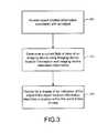
- FIG. 3depicts a flow chart of a method of displaying an indication of an object within a current field of view according to various embodiments of the present invention.
- the method of FIG. 3can include the operations of accessing object location information associated with an object at 300 , determining a current field of view of an imaging device using imaging device location information and imaging device orientation information at 310 , and providing for a display of an indication of the object if the object location information describes a location within the current field of view at 320 .
- location information associated with an objectcan be accessed.
- Object location informationcan be accessed by controller 20 of mobile terminal 10 or other means.
- An objectcan be any entity real or virtual having associated location information.
- an objectcan be mobile such as a person and the location information of the person can be retrieved from, for example, a mobile terminal 10 in the possession of the person.
- an objectcan be stationary such as a landmark and location information can be retrieved from, for example, a street address in a phone book.
- the object location informationcan be any type of information that describes the location of the object.
- the object location informationcan include longitude and latitude. Further, in some embodiments, the object location information can also include altitude.
- location information associated with an objectcan be stored in a database.
- the databasemay reside on, for example, non-volatile memory 42 of mobile terminal 10 .
- the databasecan be a contacts list or a phonebook stored on a mobile terminal.
- controller 20 of mobile terminal 10can access the database, and in particular the object location information, via requests to non-volatile memory 42 .
- the databasecan be stored remote from the mobile terminal.
- a communication systemsuch as the communications system of FIG. 2 can be used to access object location information.
- objectsmay be grouped within a category.
- a usercan define a landmark category, and designate various objects as member of the landmark category.
- object location informationcan be accessed for objects within particular categories. For example, if a category is defined and is selected, in some embodiments, object location information associated with only objects within the category can be accessed. Further, in some instances, objects may be included in a category for landmarks, restaurants, vehicle service stations, or the like. As such, categories can be defined by a user or a computerized method of defining categories can be used.
- the set of objects within a categorymay be static, that is, the set objects within the category can remain constant given a constant data set.
- An example of a static category object setcan be the family member category.
- the set of objects within a categorymay be dynamic, that is, the set objects within the category can change given a constant data set. For example, if the category is defined based upon location of the objects, the movement of objects may change the composition of the category.
- a current field of view of an imaging devicecan be determined.
- the current field of view of an imaging devicecan be determined by controller 20 of mobile terminal 10 or other means.
- the current field of viewcan be continuously determined at some regular or irregular interval.
- a current field of viewcan be the real-world area or volume that describes, using, for example, coordinates, the area or volume currently viewed from the imaging device, such as camera module 36 of mobile terminal 10 in preview mode.
- the current field of viewcan be described by a set of location coordinates, such as, for example, latitude and longitude.
- the current field of viewcan be a volume which describes the three-dimensional volume depicted in the view of an imaging device.
- a current field of viewcan be described by a set of location coordinates that may include, for example, latitude, longitude and altitude coordinates.
- location information, orientation information, and a zoom level, or some subset thereofcan be used to determine the set of location coordinates of the current field of view.
- the content of the image captured by an imaging devicecan also be used to determine the current field of view, such as, by object recognition of objects known to be at a predefined location or by the recognition of addresses visibly notable in the image.
- a display of an indication of the objectcan be provided if the object location information describes a location within the current field of view.
- the display of the indication of the objectcan be provided by controller 20 of mobile terminal 10 or other means.
- the indication of the objectcan be any media content item that has been associated with the object, such as, a picture, avatar, animation, text, or the like. For example, if a picture of a person is associated with an object, the display of the picture, as an indication of the object, can be provided. Accordingly, the indication of the object can be displayed when the location information of the object places the object in the current field of view.
- a comparisoncan be made between the object location information that was accessed at 300 , which can include object location information for a plurality of objects, and the current field of view that was determined at 310 .
- objects having object location information describing a location within the current field of viewcan be displayed.
- FIGS. 4 a through 4 edepict example displays of electronic device according to various embodiments of the invention.
- the content of FIGS. 4 a through 4 eare used for illustration purposes and do not limit to scope of the invention to the embodiments depicted therein.
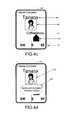
- FIG. 4 adepicts an example map area within a display 400 having various objects located within the map area.
- the example map area and example objects of FIG. 4 acan be used to describe embodiments of the invention with respect to FIGS. 4 b through 4 e .
- user 415can be located within the map area and be in possession of an electronic device having image, position and orientation capabilities.
- Object 405can be an object that is a landmark. By accessing, for example, a phonebook, object location information and other information, such as a logo or other media item, associated with object 405 can be utilized.
- object 405can be a coffee shop having object location information that describes the location where object 405 is located within the map area of display 400 .
- object 410can be an object that is a person. Using information from, for example, a contacts list, object 410 can be associated with a person. In this example, a contact list can also contain a picture associated with object 410 . Object 410 can also have associated object location information that describes the location where object 410 is located within the map area of display 400 .
- FIG. 4 bdepicts a display of an electronic device driven by a processor, such as controller 20 of mobile terminal 10 , that presents a field of view according to an embodiment of the present invention.
- FIG. 4 bdepicts an embodiment of the invention using the objects and information associated with FIG. 4 a for illustration.
- the display 420 of FIG. 4 bincludes the map image depicted in display 400 of FIG. 4 a .
- the display of the map imagecan be provided by controller 20 of mobile terminal 10 or other means.
- the display 420also includes objects 405 and 410 , and reference to the location of a user of an imaging device 415 .
- the display 420 of FIG. 4 bdepicts an example situation where user 415 implements an imaging application on an electronic device, such as the preview mode of camera module 36 .
- a current field of view 425 associated with the devicecan be defined.
- the current field of view 425can be superimposed on the map image to indicate the direction in which an imaging device is currently directed.
- a display of the current field of viewsuch as on a map image as depicted in FIG. 4 b , can be determined, and in turn, provided by controller 20 of mobile terminal 10 or other means. Note that in the example display 420 , objects 405 and 410 are located within current field of view 425 .
- indications of objects 405 and 410can be displayed because object location information associated with objects 405 and 410 describe locations within the current field of view 425 . Further, in an example embodiment where a category has been selected such that only landmarks should be displayed, only an indication of object 405 would be displayed because object 405 is associated with an object that has been defined as a landmark, that is, a coffee shop.
- Current field of view 425can also have an associated field of view center axis 430 .
- a field of view center axiscan be determined using imaging device location and orientation information. In some embodiments, imaging device zoom information can also be used to determine a field of view center axis.
- the field of view center axiscan be located central to the current field in two or three dimensions. In some embodiments, the field of view center axis can be located in any predefined location within the current field of view, such as off center.
- a field of view center axismay be described by a point within the current field of view, a line within the current field of view, or a geometric plane within a current field of view.
- a field of view center axiscan be determined by controller 20 or mobile terminal 10 , camera module 36 of mobile terminal 10 or other means.
- an actioncan be performed with respect to an associated object. For example, when the field of view center axis is aimed or focused on a particular object, additional information regarding the object can be displayed in a pop-up window, the object may be selected and an application, such as a browser, that displays a variety of information can be implemented using information associated with the object, or a selection can be provided that can initiate a telephone call to the associated object.
- a relationship between a field of view center axis that is sufficient to perform an actioncan be based on a distance measurement between the object and the field of view center axis with items less than threshold distance from the axis being considered sufficiently on-axis.
- zooming functionality of an imaging devicecan assist in aiming or focusing the field of view center axis and may also change a distance relationship necessary to perform an action. For example, in some embodiments, as a device is zoomed out to produce a wider, de-magnified image, the threshold distance sufficient to perform an action with respect to an object can be increased.
- FIG. 4 cdepicts a display of an electronic device driven by a processor, such as controller 20 of mobile terminal 10 , that presents an indication of an object according to an embodiment of the present invention.
- FIG. 4 cdepicts a display generated in accordance with an embodiment of the invention using the objects and information associated with FIG. 4 a for illustration.
- the display 445 of FIG. 4 cincludes a live image captured by an imaging device, such as the camera module 36 of mobile terminal 10 in a preview mode. Through the use of, for example, the preview mode of camera module 36 , embodiments of the invention can be implemented without the use of map images.
- the display of the live imagecan be provided by controller 20 of mobile terminal 10 , camera module 36 of mobile terminal 10 or other means.
- the display 445can also include an indication of a first object 450 and associated information 455 , indication of a second object 460 and associated information 465 , and compass display 470 , as described below.
- the live imagecan depict the real world region that is located within the current field of view.
- the current field of view of FIG. 4 cis the same as the current field of view 425 of FIG. 4 b .
- indication of a first object 450can be associated with object 405 and indication of a second object 460 can be associated with object 410 .
- a display of the live imagecan be provided by controller 20 of mobile terminal 10 , camera module 36 of mobile terminal 10 or other means.
- the indications of first and second objects 450 , 460can be displayed within the live image of display 445 .
- a user of an imaging devicecan scan the environment and identify various objects as the location information of objects fall within the current field of view of the imaging device.
- Controller 20 of mobile terminal 10 , camera module 36 of mobile terminal 10 or other meanscan provide for the display of the indications of the first and second objects 450 , 460 within the live image.
- a picture associated with the objectcan be used as the indication of the second object 460 .
- a media item or icon depicting a building structure that is associated with the objectcan be used as the indication of the first object 450 .
- information associated an objectcan be displayed with the indication of an object, such as associated information 455 and 465 .
- associated informationcan be information associated with the object including, but not limited to, the name of the object, or the location of the object.
- the indication of an objectcan be displayed within the live image at a location within the live image that is related to where the object location information is located within the current field of view.
- the size of the display of the indication of an objectcan change. For example, closer objects may have larger indications of an object, and objects that are farther away may have smaller indications of an object.
- only the indications of objects that are associated with objects that are within a selected categorycan be displayed.
- Display 445can also include a compass display 470 .
- the compass display 470can indicate to a user the current heading of an electronic compass that is associated with the imaging device.
- the orientation module 39 of mobile terminal 10can be used to provide the information depicted in the compass display 470 .
- FIG. 4 ddepicts a display of a display of an electronic device driven by a processor, such as controller 20 of mobile terminal 10 , that presents an indication of an object according to an embodiment of the present invention.
- the userhas aimed the imaging device such that the field of view center axis is within a threshold distance of the object associated with indication of an object 460 .
- the relationship between the location information associated with the indication of an object 460 and the field of view center axisis sufficient to cause an action to be performed.
- the example actioncan be to display additional information 480 and allow for selection of various other actions associated with the object.
- FIG. 4 edepicts a display a display of an electronic device driven by a processor, such as controller 20 of mobile terminal 10 , that presents a range control according to an embodiment of the present invention.
- the display 482can include a range control 484 , selected range 486 , a first object icon 488 , a second object icon 490 , and an indication of an object 450 .
- Range control 484can be used to selectively control which indications of an object will be displayed based upon the distance from the imaging device to the object. For example, in some embodiments, a range can be selected such that only objects within some predetermined distance will have indications of the objects displayed. In other embodiments, a range may be defined between two distances, such as farther than 100 meters but closer than 200 meters.
- a rangecan be predefined or selected using any means such as through a keypad or touch screen.
- the selected range 486is set between two distances such that the range includes the first object icon 488 .
- the indication of an object 450can be displayed within the live image since it is associated with the first object icon 488 .
- the example selected range 486 of display 482does not include the second object icon 490 . Accordingly, even though the object location information associated with second object icon 490 is within the current field of view, it is not within the selected range, and as such, and indication of an object associated with second object icon 490 is not displayed.
- the electronic devicesuch as mobile terminal 10
- the electronic devicewhich implements embodiments of the present invention generally operates under control of a computer program product to capture an analyze the image, generate the displays and to present the displays annotated in the manner described above.
- the computer program product for performing the methods of embodiments of the present inventionincludes a computer-readable storage medium and computer-readable program code portions, such as a series of computer instructions, embodied in the computer-readable storage medium.
- FIG. 3is a flowchart of method, apparatus and program products according to exemplary embodiments of the present invention. It will be understood that each block or step of the flowchart, and combinations of blocks in the flowchart, can be implemented by computer program instructions. These computer program instructions may be loaded onto a computer or other programmable apparatus, such as controller 20 , to produce a machine, such that the instructions which execute on the computer or other programmable apparatus create means for implementing the functions specified in the flowchart block(s) or step(s).
- These computer program instructionsmay also be stored in a computer-readable memory that can direct a computer or other programmable apparatus to function in a particular manner, such that the instructions stored in the computer-readable memory produce an article of manufacture including instruction means which implement the function specified in the flowchart block(s) or step(s).
- the computer program instructionsmay also be loaded onto a computer or other programmable apparatus to cause a series of operational steps to be performed on the computer or other programmable apparatus to produce a computer implemented process such that the instructions which execute on the computer or other programmable apparatus provide steps for implementing the functions specified in the flowchart block(s) or step(s).
- blocks or steps of the flowchartsupport combinations of means for performing the specified functions, combinations of steps for performing the specified functions and program instruction means for performing the specified functions. It will also be understood that each block or step of the flowchart, and combinations of blocks or steps in the flowchart, can be implemented by special purpose hardware-based computer systems which perform the specified functions or steps, or combinations of special purpose hardware and computer instructions.
Landscapes
- Engineering & Computer Science (AREA)
- Radar, Positioning & Navigation (AREA)
- Remote Sensing (AREA)
- General Physics & Mathematics (AREA)
- Physics & Mathematics (AREA)
- Computer Networks & Wireless Communication (AREA)
- Automation & Control Theory (AREA)
- Computer Hardware Design (AREA)
- Software Systems (AREA)
- Theoretical Computer Science (AREA)
- General Engineering & Computer Science (AREA)
- Computer Graphics (AREA)
- Signal Processing (AREA)
- Telephone Function (AREA)
Abstract
Description
Claims (13)
Priority Applications (3)
| Application Number | Priority Date | Filing Date | Title |
|---|---|---|---|
| US11/968,377US9582937B2 (en) | 2008-01-02 | 2008-01-02 | Method, apparatus and computer program product for displaying an indication of an object within a current field of view |
| EP08869387AEP2235478A1 (en) | 2008-01-02 | 2008-12-08 | Method, apparatus and computer program product for displaying an indication of an object within a current field of view |
| PCT/IB2008/055152WO2009087509A1 (en) | 2008-01-02 | 2008-12-08 | Method, apparatus and computer program product for displaying an indication of an object within a current field of view |
Applications Claiming Priority (1)
| Application Number | Priority Date | Filing Date | Title |
|---|---|---|---|
| US11/968,377US9582937B2 (en) | 2008-01-02 | 2008-01-02 | Method, apparatus and computer program product for displaying an indication of an object within a current field of view |
Publications (2)
| Publication Number | Publication Date |
|---|---|
| US20090167919A1 US20090167919A1 (en) | 2009-07-02 |
| US9582937B2true US9582937B2 (en) | 2017-02-28 |
Family
ID=40386520
Family Applications (1)
| Application Number | Title | Priority Date | Filing Date |
|---|---|---|---|
| US11/968,377Expired - Fee RelatedUS9582937B2 (en) | 2008-01-02 | 2008-01-02 | Method, apparatus and computer program product for displaying an indication of an object within a current field of view |
Country Status (3)
| Country | Link |
|---|---|
| US (1) | US9582937B2 (en) |
| EP (1) | EP2235478A1 (en) |
| WO (1) | WO2009087509A1 (en) |
Cited By (6)
| Publication number | Priority date | Publication date | Assignee | Title |
|---|---|---|---|---|
| US20180232942A1 (en)* | 2012-12-21 | 2018-08-16 | Apple Inc. | Method for Representing Virtual Information in a Real Environment |
| US11003916B2 (en) | 2017-11-03 | 2021-05-11 | Toyota Research Institute, Inc. | Systems and methods for object historical association |
| US11057734B2 (en)* | 2018-01-05 | 2021-07-06 | Cerence Operating Company | Geospecific information system and method |
| US11562325B2 (en)* | 2012-06-07 | 2023-01-24 | Apple Inc. | Intelligent presentation of documents |
| US11562540B2 (en)* | 2009-08-18 | 2023-01-24 | Apple Inc. | Method for representing virtual information in a real environment |
| US11656737B2 (en)* | 2008-07-09 | 2023-05-23 | Apple Inc. | Adding a contact to a home screen |
Families Citing this family (37)
| Publication number | Priority date | Publication date | Assignee | Title |
|---|---|---|---|---|
| US20100253787A1 (en)* | 2009-04-02 | 2010-10-07 | Isaac Grant | Method for Object Recognition and Communication of Associated Label and Other Information |
| KR101648339B1 (en)* | 2009-09-24 | 2016-08-17 | 삼성전자주식회사 | Apparatus and method for providing service using a sensor and image recognition in portable terminal |
| US8243097B2 (en)* | 2009-10-21 | 2012-08-14 | Apple Inc. | Electronic sighting compass |
| KR101631497B1 (en)* | 2009-11-13 | 2016-06-27 | 삼성전자주식회사 | Display apparatus, User terminal, and methods thereof |
| KR20110118421A (en)* | 2010-04-23 | 2011-10-31 | 엘지전자 주식회사 | Augmented remote control device, augmented remote control device control method and system |
| KR101657565B1 (en)* | 2010-04-21 | 2016-09-19 | 엘지전자 주식회사 | Augmented Remote Controller and Method of Operating the Same |
| KR101694159B1 (en)* | 2010-04-21 | 2017-01-09 | 엘지전자 주식회사 | Augmented Remote Controller and Method of Operating the Same |
| KR101655812B1 (en)* | 2010-05-06 | 2016-09-08 | 엘지전자 주식회사 | Mobile terminal and operation method thereof |
| KR101643869B1 (en)* | 2010-05-06 | 2016-07-29 | 엘지전자 주식회사 | Operating a Mobile Termianl with a Vibration Module |
| US9582166B2 (en) | 2010-05-16 | 2017-02-28 | Nokia Technologies Oy | Method and apparatus for rendering user interface for location-based service having main view portion and preview portion |
| JP5255595B2 (en)* | 2010-05-17 | 2013-08-07 | 株式会社エヌ・ティ・ティ・ドコモ | Terminal location specifying system and terminal location specifying method |
| KR20120004669A (en)* | 2010-07-07 | 2012-01-13 | 삼성전자주식회사 | World time display device and method in portable terminal |
| AT510923A1 (en)* | 2010-12-15 | 2012-07-15 | Mkw Electronics Gmbh | METHOD FOR DISPLAYING INFORMATION MADE TO ANIMAL |
| US8738754B2 (en) | 2011-04-07 | 2014-05-27 | International Business Machines Corporation | Systems and methods for managing computing systems utilizing augmented reality |
| US8913086B2 (en) | 2011-04-07 | 2014-12-16 | International Business Machines Corporation | Systems and methods for managing errors utilizing augmented reality |
| US8810598B2 (en) | 2011-04-08 | 2014-08-19 | Nant Holdings Ip, Llc | Interference based augmented reality hosting platforms |
| EP2783340A4 (en) | 2011-11-21 | 2015-03-25 | Nant Holdings Ip Llc | Subscription bill service, systems and methods |
| JP5858754B2 (en)* | 2011-11-29 | 2016-02-10 | キヤノン株式会社 | Imaging apparatus, display method, and program |
| JP2013149073A (en)* | 2012-01-19 | 2013-08-01 | Toshiba Corp | Augmented reality device, method and program |
| JP2013183433A (en)* | 2012-03-05 | 2013-09-12 | Sony Corp | Client terminal, server, and program |
| US9161167B2 (en)* | 2013-01-23 | 2015-10-13 | Qualcomm Incorporated | Visual identifier of third party location |
| US9582516B2 (en) | 2013-10-17 | 2017-02-28 | Nant Holdings Ip, Llc | Wide area augmented reality location-based services |
| CN103700128B (en)* | 2013-12-30 | 2017-02-15 | 无锡触角科技有限公司 | Mobile equipment and enhanced display method thereof |
| KR20170069092A (en)* | 2015-12-10 | 2017-06-20 | 현대자동차주식회사 | Audio video navigation device and method for providing charging station information using the audio video navigation device |
| EP3398038B1 (en) | 2016-02-04 | 2024-01-17 | Apple Inc. | Controlling electronic devices and displaying information based on wireless ranging |
| US10740502B2 (en) | 2017-02-22 | 2020-08-11 | Middle Chart, LLC | Method and apparatus for position based query with augmented reality headgear |
| US11900023B2 (en)* | 2017-02-22 | 2024-02-13 | Middle Chart, LLC | Agent supportable device for pointing towards an item of interest |
| US11900021B2 (en) | 2017-02-22 | 2024-02-13 | Middle Chart, LLC | Provision of digital content via a wearable eye covering |
| US12314638B2 (en) | 2017-02-22 | 2025-05-27 | Middle Chart, LLC | Methods and apparatus for secure persistent location based digital content associated with a three-dimensional reference |
| US12086507B2 (en) | 2017-02-22 | 2024-09-10 | Middle Chart, LLC | Method and apparatus for construction and operation of connected infrastructure |
| US12400048B2 (en) | 2020-01-28 | 2025-08-26 | Middle Chart, LLC | Methods and apparatus for two dimensional location based digital content |
| US11507714B2 (en) | 2020-01-28 | 2022-11-22 | Middle Chart, LLC | Methods and apparatus for secure persistent location based digital content |
| US11468209B2 (en) | 2017-02-22 | 2022-10-11 | Middle Chart, LLC | Method and apparatus for display of digital content associated with a location in a wireless communications area |
| US10127290B1 (en)* | 2017-07-19 | 2018-11-13 | Facebook, Inc. | Systems and methods for distributing augmented-reality effects |
| CN107806872A (en)* | 2017-09-18 | 2018-03-16 | 东莞新吉凯氏测量技术有限公司 | Augmented reality navigation method based on machine vision |
| US11640486B2 (en) | 2021-03-01 | 2023-05-02 | Middle Chart, LLC | Architectural drawing based exchange of geospatial related digital content |
| US12086943B2 (en) | 2022-08-15 | 2024-09-10 | Middle Chart, LLC | Spatial navigation to digital content |
Citations (62)
| Publication number | Priority date | Publication date | Assignee | Title |
|---|---|---|---|---|
| US5625765A (en) | 1993-09-03 | 1997-04-29 | Criticom Corp. | Vision systems including devices and methods for combining images for extended magnification schemes |
| US5682332A (en) | 1993-09-10 | 1997-10-28 | Criticom Corporation | Vision imaging devices and methods exploiting position and attitude |
| EP0867690A1 (en) | 1997-03-27 | 1998-09-30 | Nippon Telegraph And Telephone Corporation | Device and system for labeling sight images |
| US5991827A (en) | 1996-05-22 | 1999-11-23 | Geovector Corporation | Apparatus for controlling electrical devices in response to sensed conditions |
| US6037936A (en) | 1993-09-10 | 2000-03-14 | Criticom Corp. | Computer vision system with a graphic user interface and remote camera control |
| US6064398A (en) | 1993-09-10 | 2000-05-16 | Geovector Corporation | Electro-optic vision systems |
| US6173239B1 (en) | 1998-09-30 | 2001-01-09 | Geo Vector Corporation | Apparatus and methods for presentation of information relating to objects being addressed |
| US6181302B1 (en)* | 1996-04-24 | 2001-01-30 | C. Macgill Lynde | Marine navigation binoculars with virtual display superimposing real world image |
| US6208353B1 (en)* | 1997-09-05 | 2001-03-27 | ECOLE POLYTECHNIQUE FEDéRALE DE LAUSANNE | Automated cartographic annotation of digital images |
| US6278461B1 (en) | 1993-09-10 | 2001-08-21 | Geovector Corporation | Augmented reality vision systems which derive image information from other vision systems |
| US6346938B1 (en) | 1999-04-27 | 2002-02-12 | Harris Corporation | Computer-resident mechanism for manipulating, navigating through and mensurating displayed image of three-dimensional geometric model |
| US6396475B1 (en) | 1999-08-27 | 2002-05-28 | Geo Vector Corp. | Apparatus and methods of the remote address of objects |
| WO2002063243A1 (en) | 2001-02-08 | 2002-08-15 | Neil Huckle | Navigation system |
| WO2002073818A1 (en)* | 2001-03-13 | 2002-09-19 | Geovector Corporation | Systems for providing point-to-call functionality |
| US20030032436A1 (en) | 2001-08-07 | 2003-02-13 | Casio Computer Co., Ltd. | Apparatus and method for searching target position and recording medium |
| US6522292B1 (en) | 2000-02-23 | 2003-02-18 | Geovector Corp. | Information systems having position measuring capacity |
| US6535210B1 (en) | 1995-06-07 | 2003-03-18 | Geovector Corp. | Vision system computer modeling apparatus including interaction with real scenes with respect to perspective and spatial relationship as measured in real-time |
| US6795768B2 (en)* | 2003-02-20 | 2004-09-21 | Motorola, Inc. | Handheld object selector |
| US6804726B1 (en) | 1996-05-22 | 2004-10-12 | Geovector Corporation | Method and apparatus for controlling electrical devices in response to sensed conditions |
| US20050206654A1 (en)* | 2003-12-12 | 2005-09-22 | Antti Vaha-Sipila | Arrangement for presenting information on a display |
| US20050228860A1 (en)* | 2004-04-12 | 2005-10-13 | Kimmo Hamynen | Methods and apparatus for geographically based Web services |
| US7002551B2 (en)* | 2002-09-25 | 2006-02-21 | Hrl Laboratories, Llc | Optical see-through augmented reality modified-scale display |
| US7031875B2 (en) | 2001-01-24 | 2006-04-18 | Geo Vector Corporation | Pointing systems for addressing objects |
| US7088389B2 (en)* | 2000-09-19 | 2006-08-08 | Olympus Optical Co., Ltd. | System for displaying information in specific region |
| US20070027591A1 (en)* | 2005-07-27 | 2007-02-01 | Rafael-Armament Development Authority Ltd. | Real-time geographic information system and method |
| US20070070186A1 (en)* | 2005-06-30 | 2007-03-29 | Sony Corporation | Interactive communication apparatus and connecting method |
| US20070162942A1 (en)* | 2006-01-09 | 2007-07-12 | Kimmo Hamynen | Displaying network objects in mobile devices based on geolocation |
| US20070188408A1 (en)* | 2004-03-16 | 2007-08-16 | Siemens Aktiengesellschaft | Method for displaying a graphic object and communications device |
| US20070200713A1 (en)* | 2006-02-24 | 2007-08-30 | Weber Karon A | Method and system for communicating with multiple users via a map over the internet |
| US7301536B2 (en) | 1993-09-10 | 2007-11-27 | Geovector Corporation | Electro-optic vision systems |
| JP2008065092A (en)* | 2006-09-07 | 2008-03-21 | Univ Of Yamanashi | Target display method and apparatus |
| US20080132252A1 (en)* | 2006-06-01 | 2008-06-05 | Altman Samuel H | Network Manager System for Location-Aware Mobile Communication Devices |
| US20080182589A1 (en)* | 2007-01-31 | 2008-07-31 | Verizon Laboratories, Inc. | Method and system of providing instant location service |
| US20080186164A1 (en)* | 2003-09-09 | 2008-08-07 | Emigh Aaron T | Mobile surveillance |
| US20080268876A1 (en)* | 2007-04-24 | 2008-10-30 | Natasha Gelfand | Method, Device, Mobile Terminal, and Computer Program Product for a Point of Interest Based Scheme for Improving Mobile Visual Searching Functionalities |
| US7450003B2 (en)* | 2006-02-24 | 2008-11-11 | Yahoo! Inc. | User-defined private maps |
| US20080280600A1 (en)* | 2007-05-08 | 2008-11-13 | Samsung Electronics Co., Ltd. | Geographic Mobile Address Book |
| US7456847B2 (en)* | 2004-08-12 | 2008-11-25 | Russell Steven Krajec | Video with map overlay |
| US20090005981A1 (en)* | 2007-06-28 | 2009-01-01 | Apple Inc. | Integration of Map Services and User Applications in a Mobile Device |
| US20090011707A1 (en)* | 2007-07-04 | 2009-01-08 | Samsung Electronics Co., Ltd. | Method and apparatus for identifying neighboring device |
| US20090098888A1 (en)* | 2007-10-15 | 2009-04-16 | Mu Hy Yoon | Communication device and method of providing location information therein |
| US7564469B2 (en)* | 2005-08-29 | 2009-07-21 | Evryx Technologies, Inc. | Interactivity with a mixed reality |
| US20090278948A1 (en)* | 2008-05-07 | 2009-11-12 | Sony Corporation | Information presentation apparatus, information presentation method, imaging apparatus, and computer program |
| US20090289956A1 (en)* | 2008-05-22 | 2009-11-26 | Yahoo! Inc. | Virtual billboards |
| US20100004005A1 (en)* | 2007-04-11 | 2010-01-07 | Palm, Inc. | Notification on mobile device based on location of other mobile device |
| US20100110105A1 (en)* | 2008-10-31 | 2010-05-06 | Nokia Corporation | Method, apparatus and computer program product for providing synchronized navigation |
| US7728869B2 (en)* | 2005-06-14 | 2010-06-01 | Lg Electronics Inc. | Matching camera-photographed image with map data in portable terminal and travel route guidance method |
| US7737965B2 (en)* | 2005-06-09 | 2010-06-15 | Honeywell International Inc. | Handheld synthetic vision device |
| US20100203904A1 (en)* | 2009-02-06 | 2010-08-12 | Sony Corporation | Handheld electronic device |
| US20100216491A1 (en)* | 2009-02-20 | 2010-08-26 | David Winkler | Dynamic elements on a map within a mobile device, such as elements that facilitate communication between users |
| US20100229082A1 (en)* | 2005-09-21 | 2010-09-09 | Amit Karmarkar | Dynamic context-data tag cloud |
| US20100328344A1 (en)* | 2009-06-25 | 2010-12-30 | Nokia Corporation | Method and apparatus for an augmented reality user interface |
| US20110141254A1 (en)* | 2009-11-17 | 2011-06-16 | Roebke Mark J | Systems and methods for augmented reality |
| US20110221771A1 (en)* | 2010-03-12 | 2011-09-15 | Cramer Donald M | Merging of Grouped Markers in An Augmented Reality-Enabled Distribution Network |
| US20110254860A1 (en)* | 2008-12-03 | 2011-10-20 | Alcatel Lucent | Mobile device for augmented reality application |
| US20120003990A1 (en)* | 2010-06-30 | 2012-01-05 | Pantech Co., Ltd. | Mobile terminal and information display method using the same |
| US20120019557A1 (en)* | 2010-07-22 | 2012-01-26 | Sony Ericsson Mobile Communications Ab | Displaying augmented reality information |
| US8373725B2 (en)* | 2010-01-29 | 2013-02-12 | Intel Corporation | Method for providing information on object which is not included in visual field of terminal device, terminal device and computer readable recording medium |
| US20130166191A1 (en)* | 2011-12-26 | 2013-06-27 | TrueMaps LLC | Method and Apparatus of Physically Moving a Portable Unit to View an Image of a Stationary Map |
| US20140327666A1 (en)* | 2013-05-02 | 2014-11-06 | Nintendo Co., Ltd. | Display control system, display control apparatus, storage medium having stored therein display control program, and display control method |
| US20140375683A1 (en)* | 2013-06-25 | 2014-12-25 | Thomas George Salter | Indicating out-of-view augmented reality images |
| US20150378533A1 (en)* | 2014-06-27 | 2015-12-31 | Kobo Incorporated | Geosocial network for book reading and user interface thereof |
Family Cites Families (1)
| Publication number | Priority date | Publication date | Assignee | Title |
|---|---|---|---|---|
| GB2412520B (en)* | 2004-03-23 | 2006-06-21 | Nec Technologies | Image and location based information viewer |
- 2008
- 2008-01-02USUS11/968,377patent/US9582937B2/ennot_activeExpired - Fee Related
- 2008-12-08WOPCT/IB2008/055152patent/WO2009087509A1/enactiveApplication Filing
- 2008-12-08EPEP08869387Apatent/EP2235478A1/ennot_activeCeased
Patent Citations (70)
| Publication number | Priority date | Publication date | Assignee | Title |
|---|---|---|---|---|
| US5625765A (en) | 1993-09-03 | 1997-04-29 | Criticom Corp. | Vision systems including devices and methods for combining images for extended magnification schemes |
| US6064398A (en) | 1993-09-10 | 2000-05-16 | Geovector Corporation | Electro-optic vision systems |
| US7301536B2 (en) | 1993-09-10 | 2007-11-27 | Geovector Corporation | Electro-optic vision systems |
| US5815411A (en) | 1993-09-10 | 1998-09-29 | Criticom Corporation | Electro-optic vision system which exploits position and attitude |
| US5682332A (en) | 1993-09-10 | 1997-10-28 | Criticom Corporation | Vision imaging devices and methods exploiting position and attitude |
| US6031545A (en) | 1993-09-10 | 2000-02-29 | Geovector Corporation | Vision system for viewing a sporting event |
| US5742521A (en) | 1993-09-10 | 1998-04-21 | Criticom Corp. | Vision system for viewing a sporting event |
| US6307556B1 (en) | 1993-09-10 | 2001-10-23 | Geovector Corp. | Augmented reality vision systems which derive image information from other vision system |
| US6278461B1 (en) | 1993-09-10 | 2001-08-21 | Geovector Corporation | Augmented reality vision systems which derive image information from other vision systems |
| US6037936A (en) | 1993-09-10 | 2000-03-14 | Criticom Corp. | Computer vision system with a graphic user interface and remote camera control |
| US6535210B1 (en) | 1995-06-07 | 2003-03-18 | Geovector Corp. | Vision system computer modeling apparatus including interaction with real scenes with respect to perspective and spatial relationship as measured in real-time |
| US6690370B2 (en) | 1995-06-07 | 2004-02-10 | Geovector Corp. | Vision system computer modeling apparatus including interaction with real scenes with respect to perspective and spatial relationship as measured in real-time |
| US6181302B1 (en)* | 1996-04-24 | 2001-01-30 | C. Macgill Lynde | Marine navigation binoculars with virtual display superimposing real world image |
| US6098118A (en) | 1996-05-22 | 2000-08-01 | Geovector Corp. | Method for controlling electronic devices in response to sensed conditions using physical characteristic signal indicating use or anticipated use of the electronic device |
| US5991827A (en) | 1996-05-22 | 1999-11-23 | Geovector Corporation | Apparatus for controlling electrical devices in response to sensed conditions |
| US6804726B1 (en) | 1996-05-22 | 2004-10-12 | Geovector Corporation | Method and apparatus for controlling electrical devices in response to sensed conditions |
| US6414696B1 (en) | 1996-06-12 | 2002-07-02 | Geo Vector Corp. | Graphical user interfaces for computer vision systems |
| EP0867690A1 (en) | 1997-03-27 | 1998-09-30 | Nippon Telegraph And Telephone Corporation | Device and system for labeling sight images |
| US6208353B1 (en)* | 1997-09-05 | 2001-03-27 | ECOLE POLYTECHNIQUE FEDéRALE DE LAUSANNE | Automated cartographic annotation of digital images |
| US6173239B1 (en) | 1998-09-30 | 2001-01-09 | Geo Vector Corporation | Apparatus and methods for presentation of information relating to objects being addressed |
| US6346938B1 (en) | 1999-04-27 | 2002-02-12 | Harris Corporation | Computer-resident mechanism for manipulating, navigating through and mensurating displayed image of three-dimensional geometric model |
| US6396475B1 (en) | 1999-08-27 | 2002-05-28 | Geo Vector Corp. | Apparatus and methods of the remote address of objects |
| US6522292B1 (en) | 2000-02-23 | 2003-02-18 | Geovector Corp. | Information systems having position measuring capacity |
| US7088389B2 (en)* | 2000-09-19 | 2006-08-08 | Olympus Optical Co., Ltd. | System for displaying information in specific region |
| US7031875B2 (en) | 2001-01-24 | 2006-04-18 | Geo Vector Corporation | Pointing systems for addressing objects |
| WO2002063243A1 (en) | 2001-02-08 | 2002-08-15 | Neil Huckle | Navigation system |
| WO2002073818A1 (en)* | 2001-03-13 | 2002-09-19 | Geovector Corporation | Systems for providing point-to-call functionality |
| US20030032436A1 (en) | 2001-08-07 | 2003-02-13 | Casio Computer Co., Ltd. | Apparatus and method for searching target position and recording medium |
| US7002551B2 (en)* | 2002-09-25 | 2006-02-21 | Hrl Laboratories, Llc | Optical see-through augmented reality modified-scale display |
| US6795768B2 (en)* | 2003-02-20 | 2004-09-21 | Motorola, Inc. | Handheld object selector |
| US20080186164A1 (en)* | 2003-09-09 | 2008-08-07 | Emigh Aaron T | Mobile surveillance |
| US20100176949A1 (en)* | 2003-09-09 | 2010-07-15 | Emigh Aaron T | Mobile surveillance |
| US20050206654A1 (en)* | 2003-12-12 | 2005-09-22 | Antti Vaha-Sipila | Arrangement for presenting information on a display |
| US20070188408A1 (en)* | 2004-03-16 | 2007-08-16 | Siemens Aktiengesellschaft | Method for displaying a graphic object and communications device |
| US20050228860A1 (en)* | 2004-04-12 | 2005-10-13 | Kimmo Hamynen | Methods and apparatus for geographically based Web services |
| US7456847B2 (en)* | 2004-08-12 | 2008-11-25 | Russell Steven Krajec | Video with map overlay |
| US7737965B2 (en)* | 2005-06-09 | 2010-06-15 | Honeywell International Inc. | Handheld synthetic vision device |
| US7728869B2 (en)* | 2005-06-14 | 2010-06-01 | Lg Electronics Inc. | Matching camera-photographed image with map data in portable terminal and travel route guidance method |
| US20070070186A1 (en)* | 2005-06-30 | 2007-03-29 | Sony Corporation | Interactive communication apparatus and connecting method |
| US20070027591A1 (en)* | 2005-07-27 | 2007-02-01 | Rafael-Armament Development Authority Ltd. | Real-time geographic information system and method |
| US7564469B2 (en)* | 2005-08-29 | 2009-07-21 | Evryx Technologies, Inc. | Interactivity with a mixed reality |
| US20100229082A1 (en)* | 2005-09-21 | 2010-09-09 | Amit Karmarkar | Dynamic context-data tag cloud |
| US20070162942A1 (en)* | 2006-01-09 | 2007-07-12 | Kimmo Hamynen | Displaying network objects in mobile devices based on geolocation |
| US7450003B2 (en)* | 2006-02-24 | 2008-11-11 | Yahoo! Inc. | User-defined private maps |
| US20070200713A1 (en)* | 2006-02-24 | 2007-08-30 | Weber Karon A | Method and system for communicating with multiple users via a map over the internet |
| US20080132252A1 (en)* | 2006-06-01 | 2008-06-05 | Altman Samuel H | Network Manager System for Location-Aware Mobile Communication Devices |
| JP2008065092A (en)* | 2006-09-07 | 2008-03-21 | Univ Of Yamanashi | Target display method and apparatus |
| US20080182589A1 (en)* | 2007-01-31 | 2008-07-31 | Verizon Laboratories, Inc. | Method and system of providing instant location service |
| US20100004005A1 (en)* | 2007-04-11 | 2010-01-07 | Palm, Inc. | Notification on mobile device based on location of other mobile device |
| US20080268876A1 (en)* | 2007-04-24 | 2008-10-30 | Natasha Gelfand | Method, Device, Mobile Terminal, and Computer Program Product for a Point of Interest Based Scheme for Improving Mobile Visual Searching Functionalities |
| US20080280600A1 (en)* | 2007-05-08 | 2008-11-13 | Samsung Electronics Co., Ltd. | Geographic Mobile Address Book |
| US20090005981A1 (en)* | 2007-06-28 | 2009-01-01 | Apple Inc. | Integration of Map Services and User Applications in a Mobile Device |
| US20090011707A1 (en)* | 2007-07-04 | 2009-01-08 | Samsung Electronics Co., Ltd. | Method and apparatus for identifying neighboring device |
| US20090098888A1 (en)* | 2007-10-15 | 2009-04-16 | Mu Hy Yoon | Communication device and method of providing location information therein |
| US20090278948A1 (en)* | 2008-05-07 | 2009-11-12 | Sony Corporation | Information presentation apparatus, information presentation method, imaging apparatus, and computer program |
| US20090289956A1 (en)* | 2008-05-22 | 2009-11-26 | Yahoo! Inc. | Virtual billboards |
| US20100110105A1 (en)* | 2008-10-31 | 2010-05-06 | Nokia Corporation | Method, apparatus and computer program product for providing synchronized navigation |
| US20110254860A1 (en)* | 2008-12-03 | 2011-10-20 | Alcatel Lucent | Mobile device for augmented reality application |
| US20100203904A1 (en)* | 2009-02-06 | 2010-08-12 | Sony Corporation | Handheld electronic device |
| US20100216491A1 (en)* | 2009-02-20 | 2010-08-26 | David Winkler | Dynamic elements on a map within a mobile device, such as elements that facilitate communication between users |
| US20100328344A1 (en)* | 2009-06-25 | 2010-12-30 | Nokia Corporation | Method and apparatus for an augmented reality user interface |
| US20110141254A1 (en)* | 2009-11-17 | 2011-06-16 | Roebke Mark J | Systems and methods for augmented reality |
| US8373725B2 (en)* | 2010-01-29 | 2013-02-12 | Intel Corporation | Method for providing information on object which is not included in visual field of terminal device, terminal device and computer readable recording medium |
| US20110221771A1 (en)* | 2010-03-12 | 2011-09-15 | Cramer Donald M | Merging of Grouped Markers in An Augmented Reality-Enabled Distribution Network |
| US20120003990A1 (en)* | 2010-06-30 | 2012-01-05 | Pantech Co., Ltd. | Mobile terminal and information display method using the same |
| US20120019557A1 (en)* | 2010-07-22 | 2012-01-26 | Sony Ericsson Mobile Communications Ab | Displaying augmented reality information |
| US20130166191A1 (en)* | 2011-12-26 | 2013-06-27 | TrueMaps LLC | Method and Apparatus of Physically Moving a Portable Unit to View an Image of a Stationary Map |
| US20140327666A1 (en)* | 2013-05-02 | 2014-11-06 | Nintendo Co., Ltd. | Display control system, display control apparatus, storage medium having stored therein display control program, and display control method |
| US20140375683A1 (en)* | 2013-06-25 | 2014-12-25 | Thomas George Salter | Indicating out-of-view augmented reality images |
| US20150378533A1 (en)* | 2014-06-27 | 2015-12-31 | Kobo Incorporated | Geosocial network for book reading and user interface thereof |
Non-Patent Citations (1)
| Title |
|---|
| PCT Search Report and Written Opinion for Application No. PCT/IB2008/055152 dated Apr. 28, 2009. |
Cited By (7)
| Publication number | Priority date | Publication date | Assignee | Title |
|---|---|---|---|---|
| US11656737B2 (en)* | 2008-07-09 | 2023-05-23 | Apple Inc. | Adding a contact to a home screen |
| US11562540B2 (en)* | 2009-08-18 | 2023-01-24 | Apple Inc. | Method for representing virtual information in a real environment |
| US11562325B2 (en)* | 2012-06-07 | 2023-01-24 | Apple Inc. | Intelligent presentation of documents |
| US20180232942A1 (en)* | 2012-12-21 | 2018-08-16 | Apple Inc. | Method for Representing Virtual Information in a Real Environment |
| US10878617B2 (en)* | 2012-12-21 | 2020-12-29 | Apple Inc. | Method for representing virtual information in a real environment |
| US11003916B2 (en) | 2017-11-03 | 2021-05-11 | Toyota Research Institute, Inc. | Systems and methods for object historical association |
| US11057734B2 (en)* | 2018-01-05 | 2021-07-06 | Cerence Operating Company | Geospecific information system and method |
Also Published As
| Publication number | Publication date |
|---|---|
| US20090167919A1 (en) | 2009-07-02 |
| WO2009087509A1 (en) | 2009-07-16 |
| EP2235478A1 (en) | 2010-10-06 |
Similar Documents
| Publication | Publication Date | Title |
|---|---|---|
| US9582937B2 (en) | Method, apparatus and computer program product for displaying an indication of an object within a current field of view | |
| US8769437B2 (en) | Method, apparatus and computer program product for displaying virtual media items in a visual media | |
| KR102125556B1 (en) | Augmented reality arrangement of nearby location information | |
| US9910866B2 (en) | Methods, apparatuses and computer program products for automatically generating suggested information layers in augmented reality | |
| US11776185B2 (en) | Server, user terminal, and service providing method, and control method thereof for displaying photo images within a map | |
| KR102325495B1 (en) | Method and system for pushing point of interest information | |
| KR101315399B1 (en) | Terminal device and method for providing object information | |
| US20140350978A1 (en) | Method, device and storage medium for reservation based on panoramic map | |
| CN105956999B (en) | Thumbnail generation device and method | |
| US20220076469A1 (en) | Information display device and information display program | |
| JP2004226140A (en) | Information terminal device, navigation system, information processing method, and computer program | |
| CN104380290B (en) | Information processing device, information processing method | |
| TW201024671A (en) | Navigation method and system of geo-locations by identifying web pages | |
| JP5512378B2 (en) | Object display device, object display system, and object display method | |
| CN106354758A (en) | Method and device for processing house information | |
| US20110225151A1 (en) | Methods, devices, and computer program products for classifying digital media files based on associated geographical identification metadata | |
| EP3461138A1 (en) | Processing method and terminal | |
| CN106791449B (en) | Photo shooting method and device | |
| CN102456132A (en) | Positioning method and electronic device using the method | |
| US20130227383A1 (en) | Apparatus and method for searching for resources of e-book | |
| US20110307516A1 (en) | Apparatus and method for searching for content in a portable terminal | |
| JP5562814B2 (en) | Map information providing apparatus, map information providing system, map information providing method, and map information providing program | |
| US20120155708A1 (en) | Apparatus and method for measuring target point in video | |
| CN105812572B (en) | Image saving method and terminal | |
| JP2006178804A (en) | Subject object information providing method and subject object information providing server |
Legal Events
| Date | Code | Title | Description |
|---|---|---|---|
| AS | Assignment | Owner name:NOKIA CORPORATION, FINLAND Free format text:ASSIGNMENT OF ASSIGNORS INTEREST;ASSIGNORS:ANTTILA, AKSELI;JUNG, YOUNGHEE;ICHIKAWA, FUMIKO;AND OTHERS;REEL/FRAME:020581/0677;SIGNING DATES FROM 20080116 TO 20080220 Owner name:NOKIA CORPORATION, FINLAND Free format text:ASSIGNMENT OF ASSIGNORS INTEREST;ASSIGNORS:ANTTILA, AKSELI;JUNG, YOUNGHEE;ICHIKAWA, FUMIKO;AND OTHERS;SIGNING DATES FROM 20080116 TO 20080220;REEL/FRAME:020581/0677 | |
| AS | Assignment | Owner name:NOKIA TECHNOLOGIES OY, FINLAND Free format text:ASSIGNMENT OF ASSIGNORS INTEREST;ASSIGNOR:NOKIA CORPORATION;REEL/FRAME:035561/0438 Effective date:20150116 | |
| STCF | Information on status: patent grant | Free format text:PATENTED CASE | |
| AS | Assignment | Owner name:PROVENANCE ASSET GROUP LLC, CONNECTICUT Free format text:ASSIGNMENT OF ASSIGNORS INTEREST;ASSIGNORS:NOKIA TECHNOLOGIES OY;NOKIA SOLUTIONS AND NETWORKS BV;ALCATEL LUCENT SAS;REEL/FRAME:043877/0001 Effective date:20170912 Owner name:NOKIA USA INC., CALIFORNIA Free format text:SECURITY INTEREST;ASSIGNORS:PROVENANCE ASSET GROUP HOLDINGS, LLC;PROVENANCE ASSET GROUP LLC;REEL/FRAME:043879/0001 Effective date:20170913 Owner name:CORTLAND CAPITAL MARKET SERVICES, LLC, ILLINOIS Free format text:SECURITY INTEREST;ASSIGNORS:PROVENANCE ASSET GROUP HOLDINGS, LLC;PROVENANCE ASSET GROUP, LLC;REEL/FRAME:043967/0001 Effective date:20170913 | |
| AS | Assignment | Owner name:NOKIA US HOLDINGS INC., NEW JERSEY Free format text:ASSIGNMENT AND ASSUMPTION AGREEMENT;ASSIGNOR:NOKIA USA INC.;REEL/FRAME:048370/0682 Effective date:20181220 | |
| MAFP | Maintenance fee payment | Free format text:PAYMENT OF MAINTENANCE FEE, 4TH YEAR, LARGE ENTITY (ORIGINAL EVENT CODE: M1551); ENTITY STATUS OF PATENT OWNER: LARGE ENTITY Year of fee payment:4 | |
| AS | Assignment | Owner name:PROVENANCE ASSET GROUP LLC, CONNECTICUT Free format text:RELEASE BY SECURED PARTY;ASSIGNOR:CORTLAND CAPITAL MARKETS SERVICES LLC;REEL/FRAME:058983/0104 Effective date:20211101 Owner name:PROVENANCE ASSET GROUP HOLDINGS LLC, CONNECTICUT Free format text:RELEASE BY SECURED PARTY;ASSIGNOR:CORTLAND CAPITAL MARKETS SERVICES LLC;REEL/FRAME:058983/0104 Effective date:20211101 Owner name:PROVENANCE ASSET GROUP LLC, CONNECTICUT Free format text:RELEASE BY SECURED PARTY;ASSIGNOR:NOKIA US HOLDINGS INC.;REEL/FRAME:058363/0723 Effective date:20211129 Owner name:PROVENANCE ASSET GROUP HOLDINGS LLC, CONNECTICUT Free format text:RELEASE BY SECURED PARTY;ASSIGNOR:NOKIA US HOLDINGS INC.;REEL/FRAME:058363/0723 Effective date:20211129 | |
| AS | Assignment | Owner name:RPX CORPORATION, CALIFORNIA Free format text:ASSIGNMENT OF ASSIGNORS INTEREST;ASSIGNOR:PROVENANCE ASSET GROUP LLC;REEL/FRAME:059352/0001 Effective date:20211129 | |
| AS | Assignment | Owner name:BARINGS FINANCE LLC, AS COLLATERAL AGENT, NORTH CAROLINA Free format text:PATENT SECURITY AGREEMENT;ASSIGNOR:RPX CORPORATION;REEL/FRAME:063429/0001 Effective date:20220107 | |
| AS | Assignment | Owner name:RPX CORPORATION, CALIFORNIA Free format text:RELEASE OF LIEN ON PATENTS;ASSIGNOR:BARINGS FINANCE LLC;REEL/FRAME:068328/0278 Effective date:20240802 | |
| AS | Assignment | Owner name:BARINGS FINANCE LLC, AS COLLATERAL AGENT, NORTH CAROLINA Free format text:PATENT SECURITY AGREEMENT;ASSIGNORS:RPX CORPORATION;RPX CLEARINGHOUSE LLC;REEL/FRAME:068328/0674 Effective date:20240802 | |
| FEPP | Fee payment procedure | Free format text:MAINTENANCE FEE REMINDER MAILED (ORIGINAL EVENT CODE: REM.); ENTITY STATUS OF PATENT OWNER: LARGE ENTITY | |
| LAPS | Lapse for failure to pay maintenance fees | Free format text:PATENT EXPIRED FOR FAILURE TO PAY MAINTENANCE FEES (ORIGINAL EVENT CODE: EXP.); ENTITY STATUS OF PATENT OWNER: LARGE ENTITY | |
| STCH | Information on status: patent discontinuation | Free format text:PATENT EXPIRED DUE TO NONPAYMENT OF MAINTENANCE FEES UNDER 37 CFR 1.362 | |
| FP | Lapsed due to failure to pay maintenance fee | Effective date:20250228 |