US9582671B2 - Security and data privacy for lighting sensory networks - Google Patents
Security and data privacy for lighting sensory networksDownload PDFInfo
- Publication number
- US9582671B2 US9582671B2US14/639,841US201514639841AUS9582671B2US 9582671 B2US9582671 B2US 9582671B2US 201514639841 AUS201514639841 AUS 201514639841AUS 9582671 B2US9582671 B2US 9582671B2
- Authority
- US
- United States
- Prior art keywords
- customer
- share
- key
- service data
- encrypted
- Prior art date
- Legal status (The legal status is an assumption and is not a legal conclusion. Google has not performed a legal analysis and makes no representation as to the accuracy of the status listed.)
- Expired - Fee Related
Links
Images


Classifications
- G—PHYSICS
- G06—COMPUTING OR CALCULATING; COUNTING
- G06F—ELECTRIC DIGITAL DATA PROCESSING
- G06F21/00—Security arrangements for protecting computers, components thereof, programs or data against unauthorised activity
- G06F21/60—Protecting data
- G06F21/602—Providing cryptographic facilities or services
- G—PHYSICS
- G06—COMPUTING OR CALCULATING; COUNTING
- G06F—ELECTRIC DIGITAL DATA PROCESSING
- G06F21/00—Security arrangements for protecting computers, components thereof, programs or data against unauthorised activity
- G06F21/30—Authentication, i.e. establishing the identity or authorisation of security principals
- G06F21/31—User authentication
- G—PHYSICS
- G06—COMPUTING OR CALCULATING; COUNTING
- G06Q—INFORMATION AND COMMUNICATION TECHNOLOGY [ICT] SPECIALLY ADAPTED FOR ADMINISTRATIVE, COMMERCIAL, FINANCIAL, MANAGERIAL OR SUPERVISORY PURPOSES; SYSTEMS OR METHODS SPECIALLY ADAPTED FOR ADMINISTRATIVE, COMMERCIAL, FINANCIAL, MANAGERIAL OR SUPERVISORY PURPOSES, NOT OTHERWISE PROVIDED FOR
- G06Q10/00—Administration; Management
- G—PHYSICS
- G06—COMPUTING OR CALCULATING; COUNTING
- G06Q—INFORMATION AND COMMUNICATION TECHNOLOGY [ICT] SPECIALLY ADAPTED FOR ADMINISTRATIVE, COMMERCIAL, FINANCIAL, MANAGERIAL OR SUPERVISORY PURPOSES; SYSTEMS OR METHODS SPECIALLY ADAPTED FOR ADMINISTRATIVE, COMMERCIAL, FINANCIAL, MANAGERIAL OR SUPERVISORY PURPOSES, NOT OTHERWISE PROVIDED FOR
- G06Q30/00—Commerce
- G06Q30/02—Marketing; Price estimation or determination; Fundraising
- H—ELECTRICITY
- H04—ELECTRIC COMMUNICATION TECHNIQUE
- H04L—TRANSMISSION OF DIGITAL INFORMATION, e.g. TELEGRAPHIC COMMUNICATION
- H04L63/00—Network architectures or network communication protocols for network security
- H04L63/04—Network architectures or network communication protocols for network security for providing a confidential data exchange among entities communicating through data packet networks
- H04L63/0428—Network architectures or network communication protocols for network security for providing a confidential data exchange among entities communicating through data packet networks wherein the data content is protected, e.g. by encrypting or encapsulating the payload
- H04L63/0442—Network architectures or network communication protocols for network security for providing a confidential data exchange among entities communicating through data packet networks wherein the data content is protected, e.g. by encrypting or encapsulating the payload wherein the sending and receiving network entities apply asymmetric encryption, i.e. different keys for encryption and decryption
- H—ELECTRICITY
- H04—ELECTRIC COMMUNICATION TECHNIQUE
- H04L—TRANSMISSION OF DIGITAL INFORMATION, e.g. TELEGRAPHIC COMMUNICATION
- H04L67/00—Network arrangements or protocols for supporting network services or applications
- H04L67/01—Protocols
- H—ELECTRICITY
- H04—ELECTRIC COMMUNICATION TECHNIQUE
- H04L—TRANSMISSION OF DIGITAL INFORMATION, e.g. TELEGRAPHIC COMMUNICATION
- H04L67/00—Network arrangements or protocols for supporting network services or applications
- H04L67/01—Protocols
- H04L67/10—Protocols in which an application is distributed across nodes in the network
- H—ELECTRICITY
- H04—ELECTRIC COMMUNICATION TECHNIQUE
- H04L—TRANSMISSION OF DIGITAL INFORMATION, e.g. TELEGRAPHIC COMMUNICATION
- H04L67/00—Network arrangements or protocols for supporting network services or applications
- H04L67/01—Protocols
- H04L67/12—Protocols specially adapted for proprietary or special-purpose networking environments, e.g. medical networks, sensor networks, networks in vehicles or remote metering networks
- H—ELECTRICITY
- H04—ELECTRIC COMMUNICATION TECHNIQUE
- H04L—TRANSMISSION OF DIGITAL INFORMATION, e.g. TELEGRAPHIC COMMUNICATION
- H04L67/00—Network arrangements or protocols for supporting network services or applications
- H04L67/50—Network services
- H04L67/53—Network services using third party service providers
- H—ELECTRICITY
- H04—ELECTRIC COMMUNICATION TECHNIQUE
- H04L—TRANSMISSION OF DIGITAL INFORMATION, e.g. TELEGRAPHIC COMMUNICATION
- H04L9/00—Cryptographic mechanisms or cryptographic arrangements for secret or secure communications; Network security protocols
- H04L9/08—Key distribution or management, e.g. generation, sharing or updating, of cryptographic keys or passwords
- H04L9/0816—Key establishment, i.e. cryptographic processes or cryptographic protocols whereby a shared secret becomes available to two or more parties, for subsequent use
- H04L9/085—Secret sharing or secret splitting, e.g. threshold schemes
- H—ELECTRICITY
- H04—ELECTRIC COMMUNICATION TECHNIQUE
- H04L—TRANSMISSION OF DIGITAL INFORMATION, e.g. TELEGRAPHIC COMMUNICATION
- H04L9/00—Cryptographic mechanisms or cryptographic arrangements for secret or secure communications; Network security protocols
- H04L9/08—Key distribution or management, e.g. generation, sharing or updating, of cryptographic keys or passwords
- H04L9/0894—Escrow, recovery or storing of secret information, e.g. secret key escrow or cryptographic key storage
- H—ELECTRICITY
- H04—ELECTRIC COMMUNICATION TECHNIQUE
- H04L—TRANSMISSION OF DIGITAL INFORMATION, e.g. TELEGRAPHIC COMMUNICATION
- H04L9/00—Cryptographic mechanisms or cryptographic arrangements for secret or secure communications; Network security protocols
- H04L9/32—Cryptographic mechanisms or cryptographic arrangements for secret or secure communications; Network security protocols including means for verifying the identity or authority of a user of the system or for message authentication, e.g. authorization, entity authentication, data integrity or data verification, non-repudiation, key authentication or verification of credentials
- H04L9/3247—Cryptographic mechanisms or cryptographic arrangements for secret or secure communications; Network security protocols including means for verifying the identity or authority of a user of the system or for message authentication, e.g. authorization, entity authentication, data integrity or data verification, non-repudiation, key authentication or verification of credentials involving digital signatures
- H—ELECTRICITY
- H04—ELECTRIC COMMUNICATION TECHNIQUE
- H04L—TRANSMISSION OF DIGITAL INFORMATION, e.g. TELEGRAPHIC COMMUNICATION
- H04L9/00—Cryptographic mechanisms or cryptographic arrangements for secret or secure communications; Network security protocols
- H04L9/32—Cryptographic mechanisms or cryptographic arrangements for secret or secure communications; Network security protocols including means for verifying the identity or authority of a user of the system or for message authentication, e.g. authorization, entity authentication, data integrity or data verification, non-repudiation, key authentication or verification of credentials
- H04L9/3263—Cryptographic mechanisms or cryptographic arrangements for secret or secure communications; Network security protocols including means for verifying the identity or authority of a user of the system or for message authentication, e.g. authorization, entity authentication, data integrity or data verification, non-repudiation, key authentication or verification of credentials involving certificates, e.g. public key certificate [PKC] or attribute certificate [AC]; Public key infrastructure [PKI] arrangements
- H04L9/3268—Cryptographic mechanisms or cryptographic arrangements for secret or secure communications; Network security protocols including means for verifying the identity or authority of a user of the system or for message authentication, e.g. authorization, entity authentication, data integrity or data verification, non-repudiation, key authentication or verification of credentials involving certificates, e.g. public key certificate [PKC] or attribute certificate [AC]; Public key infrastructure [PKI] arrangements using certificate validation, registration, distribution or revocation, e.g. certificate revocation list [CRL]
- G—PHYSICS
- G06—COMPUTING OR CALCULATING; COUNTING
- G06Q—INFORMATION AND COMMUNICATION TECHNOLOGY [ICT] SPECIALLY ADAPTED FOR ADMINISTRATIVE, COMMERCIAL, FINANCIAL, MANAGERIAL OR SUPERVISORY PURPOSES; SYSTEMS OR METHODS SPECIALLY ADAPTED FOR ADMINISTRATIVE, COMMERCIAL, FINANCIAL, MANAGERIAL OR SUPERVISORY PURPOSES, NOT OTHERWISE PROVIDED FOR
- G06Q2220/00—Business processing using cryptography
- H—ELECTRICITY
- H04—ELECTRIC COMMUNICATION TECHNIQUE
- H04W—WIRELESS COMMUNICATION NETWORKS
- H04W84/00—Network topologies
- H04W84/18—Self-organising networks, e.g. ad-hoc networks or sensor networks
Definitions
- Embodiments of the present disclosurerelate generally to security and data privacy in a networked environment, and more particularly, but not by way of limitation, to protecting customer data collected by sensor networks.
- sensor networksare being used in a wide range of application areas.
- data collected by sensor networksmay be used for environmental monitoring, security and surveillance, logistics and transportation, control and automation, and traffic monitoring.
- Security and privacyis one of the major concerns when the sensor networks collect sensor data involving human participants.
- Adequate security measuresmay be implemented in a system that collects, stores and processes the sensor data to preserve the privacy of the human participants and to prevent unauthorized access to the sensor data collected by the sensor network.
- FIG. 1is a diagram of a lighting sensor network suitable for use in various embodiments.
- FIG. 2illustrates a block diagram of a lighting sensor network in communication with a public key infrastructure (PKI) and a customer device according to example embodiments.
- PKIpublic key infrastructure
- FIG. 3Aillustrates various examples of certificates and private keys used to implement security within a lighting sensor network, according to example embodiments.
- FIGS. 3B-3Dillustrate various block diagrams of a lighting sensor network having keys, certificates and shares distributed among multiple devices within the lighting sensor network or devices in communication with the lighting sensor network, according to example embodiments.
- FIG. 4is a diagram illustrating a method for a customer to create a certificate and key-pair, according to example embodiments.
- FIG. 5is a diagram illustrating a method for a customer to decrypt and access data stored at a service data platform, according to example embodiments.
- FIG. 6is a diagram illustrating a method for a customer to recover a private key, according to example embodiments.
- FIG. 7illustrates a diagrammatic representation of a machine in the form of a computer system within which a set of instructions may be executed for causing the machine to perform any one or more of the methodologies discussed herein, according to an example embodiment.
- public key cryptography implemented with a private key sharing schememay also be used to secure customer data from unauthorized access by third parties.
- the customer datamay represent sensor data collected by sensor nodes within a sensor network. Examples of sensor data include motion detection data, ambient light sensor data, audio data, image data, video data, and vibration data.
- the customer datamay contain sensitive identification information that requires protection to maintain the privacy of individuals represented by the customer data.
- the sensitive identification informationmay include personally identifiable information and customer identifiable information.
- Systems having access to sensitive identification informationmay be required to conform to various data privacy laws and regulations. A company or entity that owns or manages such a system may implement privacy guidelines to conform to data privacy laws, regulations, and best practices.
- a data privacy guidelinemay include the following provisions: data privacy is managed end-to-end; data privacy is supported during data collection, storage, and display; private data includes personally identifiable information and customer identifiable information; audio related sensing complies with federal wiretapping laws; all data accessed is password protected; data is only stored when required; personally identifiable information and customer identifiable information is transmitted when the relevant privacy guidelines are met, transmitted personally identifiable information and the customer identifiable information is encrypted; and the light infrastructure owners are required to post appropriate signs and get explicit written consent when required from individuals and entities.
- the privacy guidelines for ambient dataare based on prevailing laws and regulations and are developed to benefit end-users of the applications and services while protecting the privacy of individuals. Various guidelines may evolve based on the laws and user preferences as applications and services are developed and deployed.
- sensor nodes within lighting sensor networksmay be configured to obtain various sensor data, such as video and audio data.
- video camera sensors coupled to or residing within sensor nodes within a parking garage or parking lotmay capture video and audio data of cars moving about.
- the obtained sensor datamay often contain identifying data of persons (also referred to as sensitive identification information) within the infrastructures, such as motorists driving their cars within parking decks that include sensor nodes.
- video datamay include faces or likenesses of people, license plate numbers, or other distinguishing information about their respective automobiles.
- the owners of lighting sensor networks who are collecting raw sensor data at the sensor nodesmay have legal obligations or other obligations to protect the privacy of persons whose identity may be potentially discovered by accessing the sensor data collected or recorded by the sensor nodes within a lighting sensor network.
- Some examples of sensitive identification information that may require additional privacy measuresmay include face identification, media access control (MAC) addresses on mobile phones, and license plates of cars.
- MACmedia access control
- public key cryptographymay be used to protect customer data from unwanted sharing or access within a networked environment.
- the public key cryptographymay be implemented using a public key infrastructure (PKI) to create digital certificates which certifies public keys with digital signatures.
- PKIpublic key infrastructure
- the networked environmentmay include a lighting sensor network that includes a sensor network in communication with a server system representing a sensor data storage and management platform (also referred to as a service data platform) via a network (e.g., a wide area network (WAN)).
- a sensor data storage and management platformalso referred to as a service data platform
- WANwide area network
- This framework for collecting and processing sensor datasupports end-to-end security and may be used to implement various privacy guidelines.
- the sensor networkmay be coupled to a lighting infrastructure (or other infrastructure) that is capable of providing the sensor nodes within the sensor network with mechanical support for mounting the sensor nodes, and additional power and networking capabilities to the sensor nodes.
- some or all of the sensor nodesmay be attached, directly or indirectly, to lighting fixtures within the lighting infrastructure.
- Public key cryptographymay be used to reduce or minimize security problems and threats by sending encrypted sensor data over the Internet or other networks and storing the sensor data in an encrypted form at the service data platform. Public key cryptography may also be used to allow or limit access to the sensor data (which may contain sensitive identification information) to only those parties who are authorized to have access to such data.
- public key cryptographymay be used by the lighting sensor network to protect the customer data collected at the sensor nodes.
- the sensor data collected at the sensor nodesmay be encrypted, using a customer public key, at the sensor nodes.
- the encrypted sensor datais transported to the service data platform and stored as encrypted sensor data until the customer decides to access the sensor data.
- the sensor datais decrypted using a customer private key sharing scheme in various embodiments.
- the public key cryptographyallows the customer to manage and control the private key, and therefore limit access to its sensor data to only authorized parties.
- computing devices associated with the lighting sensor networkmay generate data (e.g., certificates, shares, keys, etc.) that only in combination may decrypt encrypted sensor data obtained by sensor nodes.
- datae.g., certificates, shares, keys, etc.
- three types of keys and associated certificatesare used.
- the three types of keys and associated certificatesmay be referred as device, server and customer keys and certificates.
- the device keys and device certificatesare associated with the lighting nodes (and possibly other devices within the lighting network).
- the server keys and server certificatesare associated with the service data platform which represents a server system having multiple servers.
- the customer keys and customer certificatesare associated with customers.
- the customersmay be customers of the service data platform or service provider who may be the owners of the lighting network.
- the customersmay also be customers of the owners of the lighting network.
- the lighting sensor networkmay rely on these three types of keys and certificates.
- the number of each of the types of keys and certificatesdepends on the number of devices within the lighting sensor network that is participating or implementing the public key cryptography scheme described in the various embodiments.
- the various keys, certificates and shares, associated with the various deviceswill be discussed in more detail with FIGS. 3B-3D .
- the customer private keymay be split into three shares: a customer share, a server share, and a third-party share (e.g., trusted agency, escrow company) such that sensor data may only be decrypted using no less than two of the three shares.
- a private key sharing schemeBy using a private key sharing scheme, outside parties hoping to gain access to encrypted data recorded by sensor nodes may not be able to decrypt the data and thus reveal sensitive identity information without the permission or authorization of customers (or owners of the lighting sensor network or sensor nodes) and the designated number of shares from the private key.
- customersmay choose to provide the service data platform with an encrypted local share of their customer share in order to facilitate access to the encrypted sensor data stored by the service data platform by the customer upon their request.
- the combination of the server share the encrypted local sharemay be used to decrypt the encrypted sensor data.
- the encrypted local sharemay be password protected.
- customersmay be enabled to access the encrypted sensor data obtained by sensor nodes via a web interface using the customer share (or encrypted local share of the customer share) of the private key.
- the various embodimentsprovide methods, devices, systems, and non-transitory process-readable storage media for security and data privacy utilized within a lighting sensor network.
- Such networksare described within U.S. Provisional Application No. 61/948,817, filed Mar. 6, 2014 entitled “Security and Data Privacy for Lighting Sensory Network,” the contents of which are incorporated by reference herewith in its entirety, and U.S. Non-Provisional patent application Ser. No. 14/024,561, entitled “Networked Lighting Infrastructure for Sensing Applications,” filed Sep. 11, 2013 and its related U.S. Provisional Application No. 61/699,968, of the same title, filed Sep. 12, 2012.
- the NetSense lighting sensor network platformdeveloped by Sensity Systems Inc. of Sunnyvale Calif., provides an example of a lighting sensor network that may be used to implement various embodiments described.
- the NetSense frameworkenables deployment of a variety of sensors using a lighting infrastructure that allows applications to securely access sensor data information, which may represent sensitive identification information.
- NetSensehas been architected to support the end-to-end data security and evolving set of privacy guidelines.
- the key components of NetSenseincludes end-point sensor data collection devices (e.g., sensor nodes), a server platform that processes and enables applications to securely access the sensor data (e.g., service data platform) and a user interface that displays the sensor data.
- datamay be encrypted for storage or before transmission. This ensures that even if the access to data is compromised, encryption will make the data unusable.
- device level datae.g., data at the sensor nodes
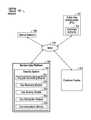
- FIG. 1illustrates an implementation of a lighting sensor network 160 suitable for use in various embodiments.
- the lighting sensor network 160enables deployment of a variety of sensors 111 using a lighting infrastructure and allows the sensor data to be securely transported to the service data platform 140 for secure storage and processing at the request of customers.
- FIG. 1shows the various components of the lighting sensor network 160 .
- the lighting sensor network 160represents a lighting infrastructure integrated with a sensor network 100 that is networked with a service data platform 140 .
- the sensor nodes 100include one or more sensors 111 .
- the lighting infrastructureincludes the sensor nodes 100 , attached directly or indirectly to lighting fixtures within the lighting infrastructure.
- the sensor nodes 100alone or in combination with the lighting infrastructure, may form the sensor network 100 .
- the sensor network 100includes multiple spatially distributed sensor nodes 100 used to monitor physical and environmental conditions, such as temperature, sound, pressure, light, traffic (vehicles and people), and vibrations.
- the sensor nodes 100may include several components, for example, multiple sensors, a radio transceiver with an internal antenna, a microcontroller, an electronic circuit for interfacing with sensors and a power supply.
- the sensor nodes 100may include other networking interfaces.
- the controllerincludes memory for storing the various certificates, keys, and shares locally at the sensor nodes 100 .
- the Customer Certificate 1100 , the Server Root Certificate 2000 , the Device Certificate 3100 , and the Device Private Key 3201may be stored locally at the sensor nodes 100 a in the example embodiment shown in FIG. 3B .
- the sensor network 100usually monitors an area such as a customer site.
- the sensor nodes 100may be attached to lighting fixtures 105 located at a customer site representing a lighting infrastructure.
- the lighting infrastructure(or other types of infrastructures) may be capable of providing power to the sensor nodes and mechanical or physical support for the sensor nodes.
- the infrastructuremay also provide additional networking communication interfaces for the sensor network 100 .
- the sensor nodes 100are deployed within the site to monitor various conditions, events, or phenomenon that provides insights to users of the lighting sensor network 160 . In alternative embodiments, only some of the lighting fixtures 105 within a lighting infrastructure are attached, directly or indirectly, to sensor nodes 100 .
- the sensor nodes 100communicate over a network, such as a wide area network (WAN) 130 with the service data platform 140 , which may represent one or more application servers residing in a cloud computing environment.
- the sensor network 100communicates with a local area network (LAN) or wide area network (WAN) through a gateway.
- the gatewayacts as a bridge between the WAN 130 and the other network (e.g., LAN, which is not shown).
- the sensor data collected at the sensor nodes 100 in the sensor network 100may be securely transported to a remote server system (represented by the service data platform 140 ) for storage and processing. This enables data to be stored and processed by devices with more resources, for example, in a remotely located server system residing in a cloud computing environment.
- the service data platform 140may be owned and operated by an entity referred to as a service provider.
- the owner of the lighting infrastructuremay be referred to as a customer of the service provider.
- the customer of the service providermay allow third parties to access to the sensor data collected at the sensor nodes 100 .
- the sensor data collected at the sensor nodes 100may include sensitive identification information requiring appropriate security measures to be implemented by the lighting sensor network 160 to maintain the confidentiality and privacy of the sensor data, either raw sensor data, event sensor data, or processed sensor data.
- public-key cryptography using key-pairsmay be used by the lighting sensor network 160 to ensure there is no unauthorized access to the sensor data and the data is securely transported.
- Sensor data collected by the sensor nodes 100may be encrypted by the sensor nodes 100 and then securely transported over the WAN 130 to be stored by the service data platform 140 .
- Secure connections between the sensor nodes 100 and the service data platform 140may be established using the various digital certificates and private keys issued to the sensor nodes, the servers, and the customer devices.
- the sensor data stored by the service data platform 140may be stored as encrypted sensor data until an authorized user requests access to the encrypted sensor data.
- the encrypted sensor datamay be decrypted by the service data platform 140 in accordance with a private key sharing scheme or transported from the service data platform 140 to be decrypted by another system or offline from the service data platform 140 .
- the private key sharing scheme used for decrypting the encrypted sensor datawill be described in further detail below.
- the service data platform 140also provides both programmatic access thru API servers and web access thru web servers to data stored in the service data platform 140 .
- Datamay be stored in the service data platform 140 in one more databases, accessed through a database server.
- the service data platform 140may provide application programming interfaces (APIs) for third party applications to access sensor data stored in the service data platform 140 .
- the service data platform 140may also provide access to the sensor data via web servers.
- the service data platform 140may represent a platform for managing sensor data that includes database services for customers. Developers of third party application 150 may access the sensor data stored in the database and build their own applications utilizing the sensor data. Other online data services may also be provided by the service data platform 140 , for example, analyzing and processing the sensor data which are accessible to authorized users of the service data platform 140 .
- the service data platform 140may include APIs and interfaces for third party application developers, a middleware containing the business logic needed for managing and processing the sensor data, a storage model suitable for the efficient storage and retrieval of large volumes of the sensor data, and appropriate security measures that are available to customers for protecting unauthorized access to their sensor data.
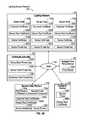
- FIG. 2illustrates a block diagram of a lighting sensor network 160 in communication with a public key infrastructure (PKI) 101 and a customer device 104 according to example embodiments.
- the lighting sensor network 160includes a sensor network 100 and a service data platform 140 .
- the service data platform 140includes a security system 144 that may be used in various embodiments to implement the public key cryptography.
- the security system 144includes a key pair generating module 141 , a key recovery module 142 , a key sharing module 143 , a key distribution module 145 , and a communications module 146 .
- the communications module 146may be used by the service data platform 140 to communicate with the PKI 101 , the certificate authority 102 , the sensor network 100 , the customer device 104 , and the trusted third party device (not shown) via the WAN 130 .
- the key distribution module 145may be used to distribute various keys, certificates, and shares to the various devices within the lighting sensor network 160 or devices in communication with the lighting sensor network 160 (e.g., the customer device 104 or the trusted third party device (not shown).
- the key sharing module 143is described below in conjunction with FIGS. 4-6 .
- the key sharing module 143may be used to create the shares of the private key and also to reconstruct the private key using a subset of the shares required to implement the private key sharing scheme.
- the key recovery module 143is described below in conjunction with FIG. 6 .
- the key-pair generating module 141provides functionality to generate a key-pair using various public key cryptography algorithms.
- the PKI 101is used to create the digital certificates in example embodiments.
- the communications module 146 of the service data platform 140sends the public key portion of a key-pair to the PKI 101 to be certified with the digital signature of the PKI 101 .
- the service data platform 140keeps the private keys (used to decrypt data) secret and does not send it to the PKI 101 .
- the certificate authority 102stores the root private keys for the devices, servers, and customers. The root private keys are difficult to revoke and they are kept very secure by the service data platform 140 .
- the PKI 101creates a root certificate and other associated certificates for the various computing devices within the networked environment.
- the PKI 101may create a customer root certificate and one or more customer certificates associated with a customer key-pair; a server root certificate and one or more server certificates associated with a server key-pair; and a device root certificate and one or more device certificates associated with a device key-pair.
- Sensitive identification information(e.g., sensor data collected at the sensor nodes 100 ) may be exchanged over the Internet by relying on the PKI 101 for security.
- the PKI 101may include hardware and software that may be used to implement policies and standards related to keys and digital certificates.
- the PKI 100may include the following components:
- the key-pairmay be generated by a customer and who then obtains the certificates from the PKI 101 before distributing the various digital certificates and keys to the various computing devices within a networked environment.
- a root certificatemay be the base to issue multiple intermediate certificates.
- a root certificateis part of a PKI scheme.
- the root certificatemay be based on the ITU-T X. 509 standard for public key infrastructure (PKI) and Privilege Management Infrastructure (PMI), which often includes a digital signature from a certificate authority.
- PKIpublic key infrastructure
- PMIPrivilege Management Infrastructure
- the digital certificatesare verified using a chain of trust.
- the trust anchor for the digital certificateis the root certificate authority.
- FIG. 3Aillustrates an example of a certificate 301 and a root certificate 302 .
- the information included within the certificates 301 and 302include the public key information, a cryptographic signature of the certificate authority 102 , identification information of the key-pair owner.
- the certificate 301includes information about the root certificate 302 that was used to sign that particular certificate 302 , in addition to the cryptographic signature of the root certificate 302 .
- the certificate authority 102issues a digital certificate to entities and individuals after verifying their identity.
- a private key 303 and a private key 304that uses a private sharing scheme.
- the private key 304is divided into a first share 140 a , a second share 104 a , and a third share 103 a.
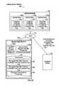
- FIG. 3Billustrates a high level block diagram of a lighting sensor network 160 implementing public-key cryptography using a private key sharing scheme for customer key-pairs.
- the lighting sensor network 160includes the lighting network 100 , the service data platform 140 in communications with a customer device 104 and a trusted third party device 103 .
- the sensor nodes 100 amay encrypt the sensor data available at the sensor nodes 100 a and establish a secure connection with the service data platform 140 over the WAN 130 .
- the customer device 104may represent a client device used by the customer to log into the service data platform 140 to request a new customer key-pair.
- the customermay request the customer key-pair while installing or updating the lighting network 100 to ensure secure communications between the devices within the lighting sensor network 160 and unauthorized access to its customer data.
- the customermay represent the owner of a lighting infrastructure, owner of a sensor network 100 , owner of sensor data or any else authorized to collect and access sensor data from the sensor nodes 100 .
- the customermay also represent the customer of the service data platform 140 .
- the certificate authority 102 within the PKI 101issues the digital certificates associated with key-pairs.
- the digital certificatecontains the public key and the identity of the owner of the key-pair.
- the ownermay be the customer for a customer key-pair.
- the digital certificateprovides a confirmation of validation by the certificate authority 102 that the customer public key contained in the digital certificate belongs to the party (e.g., customer) noted in the digital certificate.
- the PKI 101distributes the digital certificates to the service data platform 140 .
- digital certificates associated with a customer key-pairwhich contains the public key and identity of the owner, are distributed to the sensor nodes 100 within the lighting network 100 .
- the Customer Certificates 1100represent certified public keys owned by the customer.
- the sensor nodes 100 amay encrypt the sensor data collected at the sensor nodes 100 and other data available at the sensor nodes 100 a .
- a secure connectionmay be established between the sensor nodes 100 a within the sensor network 100 and the service data platform 140 to transport the encrypted sensor data.
- the secure connectionmay be established by one or more key-pairs associated with the sensor nodes 100 and the data service platform 140 .
- the sensor nodes 100 amay represent client devices that use the certificates to verify the signature on the certificates, as part of the verification before establishing a secure connection between the lighting network 100 and the service data platform 140 .
- a sensor node 100 amay attempt to establish a connection with the service data platform 140 and the service data platform 140 and sensor node 100 a mutually authenticate each other.
- the service data platform 140may present its Server Certificate 2100 to the sensor node 100 a .
- the sensor node 100 auses a Server Root Certificate 2000 , stored locally at the sensor node 100 a , to verify the signature on the Server Certificate 2100 is traceable back to the Server Root Certificate 2000 and to authenticate the service data platform 140 .
- the sensor node 100 asends the Device Certificate 3100 to the service data platform 140 .
- the service data platform 140uses the Device Root Certificate 3000 , stored locally at the service data platform 140 , to authenticate that the sensor node 100 a .
- the service data platform 140is able to trace the Device Certificate 3100 back to the Root Device Certificate 3000 .
- the digital certificatescertify the ownership of a public key by the named subject of the certificate. The digital certificate allows others to rely upon signatures or assertions made by the private key that corresponds to the certified public key.
- the matching customer private key, used for decrypting the encrypted sensor datais not made available publicly, but is kept secret by the owner or customer who generated the key-pair. In some embodiments, only participants in the private sharing scheme may have access to a share of the customer private key.
- the service data platform 140manages the customer private key for the customer by using a secret sharing algorithm or scheme. In various embodiments, the customer private key (also referred to a “secret”) is distributed among a group of participants, each of whom is allocated a share of the secret. In some embodiments, the key distribution module 145 (shown in FIG. 2 ) is responsible for distributing the shares of the secret to various devices or participants in the secret sharing scheme.
- the secret or customer private keycan be reconstructed when a sufficient number of shares are combined together.
- the key sharing module 143(shown in FIG. 2 ) may be used to create the shares by using the secret sharing algorithm and may also be used to reconstruct the private key by combining multiple shares of the private key as specified by the secret sharing scheme being used. None of the individual shares can decrypt the encrypted data on its own.
- the customer private keyis destroyed or disposed of once the shares are created from the private key.
- the customer private keywas split into three shares (e.g., the first share 140 a , the second share 104 a and the third share 103 ) prior to being destroyed or otherwise disposed of.
- the second share referred to as 104 arepresents customer share stored by a server on the service data platform 140 and the second share referred to as 104 b represents the customer share that is returned to the customer. Any combination of two of the three shares 140 a , 104 a (or 104 b ), and 103 a is sufficient to decrypt the encrypted to sensor data stored in the service data platform 140 in accordance with the private key sharing scheme.
- the key-pair generating module 141shown in FIG.
- each of the three sharescontains at least two thirds of the customer private key so that a combination of two of the shares 140 a , 104 a , and 103 a may be used to reconstruct the customer private key.
- the private sharing schememay use more than three shares with each share including at least a portion of the customer private key necessary to reconstruct the customer private key with the designated number of shares specified in the private key sharing scheme.
- the first share 140 a and the second share 104 awhich are both stored on the service data platform 140 , and may be used to decrypt the encrypted sensor data when the service data platform 140 receives a request from an authorized user.
- the authorized usermay log into the service data platform 140 and provide the password or passcode for the second share 104 a , prior to generating a request to access the encrypted sensor data.
- the authorized usermay use the customer device 104 to log onto the service data platform 140 .
- a combination of the second share 104 a and the third share 103 amay be used to decrypt the encrypted sensor data.
- the first share 140 a and the third share 103 amay be used to decrypt the encrypted sensor data.
- the customer through the customer device 104may request the encrypted sensor data be transmitted over the WAN 130 to the trusted third party device 103 or the customer device 104 .
- the encrypted sensor datamay be decrypted by the combination of the second share 104 b and the third share 103 a .
- the customermay decide to transport the encrypted sensor data off the service data platform 140 before decrypting the encrypted sensor data. In other words, the sensor data is decrypted offline from the service data platform 140 .
- the trusted third party device 103may be an escrow company who holds the third share 103 a in escrow.
- the third share 103 amay be securely sent to the service data platform 140 and used to decrypt the encrypted sensor data stored on the service data platform 140 .
- the third share 103may also be password encrypted for additional security.
- the customermay decide to manage access to the private key itself such that the service data platform 140 may not decrypt any of the encrypted sensor data collected and stored on the service data platform.
- Request for key-pairs and distribution of the key-pairsmay be handled by the customer on a device separate from the service data platform 140 .
- the customer public keysmay be provided to the service data platform 140 for distribution by the service data platform 140 to the sensor nodes 100 .
- the customer private keymay not be provided to the service data platform 140 and the private key sharing scheme may be managed by the customer or another party selected by the customer.
- the service data platform 140primarily provides database services to store the encrypted sensor data.
- the customer private keyis split or divided into three shares.
- the first share 140 amay be referred to as the server share
- the second share 104 a (and 104 b )may be referred to as the customer share
- the third share 103 amay be referred to as the trusted third party share.
- the service data platform 140provides security functionality to split the private key into three shares and then dispose of the customer private key once the three shares are created.
- the key pair generating module 140(shown in FIG. 2 ) may be used to split the private key into multiple shares.
- the private key sharing schememay split the private keys into any number of shares (e.g., four shares, five shares, etc.), where a subset of the number of shares is required to be combined to decrypt the encrypted sensor data.
- the first share 140 a representing the server sharemay be stored in plain text in a database in the service data platform 140 .
- the second share 104 arepresents a password encrypted local customer share, may also be stored in a database in the service data platform 140 .
- the second share 104 arequires a customer password before the encrypted sensor data can be decrypted.
- the second share 104 bwhich may or may not be encrypted, is returned to the customer.
- the customermay use the customer share 104 b in combination with the third share 103 a , to decrypt the encrypted sensor data offline from the service data platform 140 .
- a trusted third partymay represent any entity selected by the customer who represents a trusted party.
- the trusted third partymay be an escrow company.
- the trusted third party sharereferred to as the third share 103 a , may be securely transferred to the trusted third party for safe keeping in the event the second shares 104 a and 104 b are lost, or for use in offline decrypting in combination with the second share 104 b.
- users accessing the lighting sensor network 160 and computers (or computing devices) within the lighting sensor network 160may both securely exchange data over networks such as the Internet and verify the identity of the other party.
- sensor data generated at the sensor nodes 100may be encrypted and securely transported over a network to the service data platform 140 .
- the encrypted sensor datamay be stored at the service data platform 140 and decrypted by using a private key sharing scheme.
- the service data platform 140may verify that that the encrypted sensor data was provided by customer devices (e.g., sensor nodes 100 owned by the customer).
- the customer certified public key(represented by the Customer Certificate 1100 ) may be widely distributed to the various sensor nodes 100 a .
- the key distribution module 145may distribute the Customer Certificates 1000 .
- the customer private keyis made available only to the participants of the private key sharing scheme.
- the sensor nodes 100 amay collect raw sensor data (and other data available at the sensor nodes 100 a ) which is encrypted before being transported over a network (e.g., WAN 130 ) to the service data platform 140 for storage, and in some cases, for further processing.
- a networke.g., WAN 130
- the service data platform 140may represent remote servers located in a cloud computing environment.
- the encrypted sensor datamay be stored in its encrypted form until a request to access the encrypted sensor data is received by the service data platform 140 from an authorized user.
- the encrypted datamay be decrypted using two of the three shares shown in FIG. 3B in example embodiments.
- one or more of the shares of the customer private keymay request a passphrase (or passcode) before decrypting.
- a passphrasemay be supplied manually.
- a usermay be allowed to store the passphrase locally so that messages can be decrypted automatically.
- the second share 104 amay require a passphrase, either manual or automatically.
- responsibility for the customer private keyis shared between multiple parties, such as the administrator or owner of the service data platform 140 , the customer, and a trusted third-party.
- a sharing techniquemay be implemented using cryptographic key-sharing to split the key into multiple parts, some of which can be used together to recover, reconstruct, or replace the entire customer private key.
- the service data platform 140provides a server to hold on to the password encrypted local customer share. In some examples, the service data platform 140 is not able to decrypt the local share unless the customer provides the password, which may need to be provided at least for each login session to the server.
- FIG. 3Billustrates the various keys and digital certificates that may be used to implement public key cryptography for data security of the lighting sensor network 160 , according to example embodiments.
- the computing devices in the lighting sensor network 160 and users of the lighting sensor network 160are assigned signed key-pairs for secure communication.
- the keys and certificates in useare described below.
- the Server Root Certificate 2000 and Server Root Private Key 2200represent the certificate and key-pair that is used to sign all Server Certificates 2100 .
- the Server Root Certificate 2000is distributed to all devices (e.g., sensor nodes 100 e ) that connect to a server in the service data platform 140 .
- FIG. 3Billustrates the Server Root Certificate 2000 stored locally at the sensor nodes 100 a .
- the Server Root Private Key 2200must be kept very secure, as it is difficult to revoke. In some embodiments, the Server Root Private Key 2200 is kept in a secure location that is only known to the certificate authority 102 .
- the Server Root Private Key 2200is only used for signing the Server Certificates 2100 .
- the Server Private Key 2201corresponds to a Server Certificate 2100 and is different from the Server Root Private Key 2200 .
- the Server Certificate 2100 and Server Private Key 2200represent the certificate and key-pair used by the server in the service data platform 140 for all device connections to that server.
- the Server Certificates 2100are signed by the Server Root Private Key 2300 .
- FIG. 3Billustrates the Server Certificate 2100 and the Server Private Key 2200 stored locally at the service data platform 140 .
- the Device Root Certificate 3000 and Device Root Private Key 3200represent the certificate and key-pair used to sign all Device Certificates 3100 .
- the Device Root Certificate 3000is distributed to all servers within the service data platform 140 to validate the identity of devices (e.g., sensor nodes 100 a ).
- the Device Root Private Key 3200must be kept very secure, as it is difficult to revoke. In some embodiments, the Device Root Private Key 3200 is kept in a secure location that is only known to the certificate authority 102 .
- the Device Root Private Key 3200is only used for signing the Device Certificates 3100 .
- the Device Private Key 3201corresponds to a Device Certificate 3100 and is different from the Device Root Private Key 3200 .
- the Device Certificate 3100 and Device Private Key 3201represent the certificate and key-pair that gets assigned to any node, service bridge and any other wireless station or client of a server in the service data platform 140 .
- the Device Certificates 3100are signed by the Device Root Private Key 3200 .
- the Customer Root Certificate 1000 and Customer Root Private Key 1200represent the certificate and key-pair used to sign all Customer Root Certificates 1100 .
- the Customer Root Certificate 1100is distributed to servers within the service data platform 140 and may be used to validate the identity of customers when they log in.
- the Customer Root Private Key 1200must be kept very secure, as it is difficult to revoke. In some embodiments, the Customer Root Private Key 1200 is kept in a secure location that is only known to the certificate authority 102 .
- the Customer Root Private Key 1200is only used for signing the Customer Certificates 1100 .
- the customer private keycorresponds to a Customer Certificate 1100 and is different from the Customer Root Private Key 1200 .
- the customer private keyis reconstructed using a private key sharing algorithm.
- the Customer Certificate 1100 and customer private keyrepresent the key-pair that is used for encrypting all customer identifiable information and the person identifiable information at the sensor node 100 a .
- the customer private keyis under the control of the customer and is signed by the server.
- the Customer Certificate 1100is distributed to the devices owned by the customer (e.g., the sensor nodes 100 a ) for encryption of data. Once the data is encrypted by those devices it cannot be decrypted because those devices never possess the corresponding customer private key.
- the key distribution module 145is responsible for distributing the various keys, certificates, and shares to the various devices shown in FIG. 3B in example embodiments.
- the sensor nodes 100 a(or devices) store the following certificates and keys locally: the Device Certificate 3100 and the Device Private Key 3201 ; the Server Root Certificate 2000 ; and the Customer Certificate 1100 .
- the service data platform 140(or server) stores the following certificates and keys locally: the Server Certificate 2100 and the Server Private Key 2201 ; the Customer Root Certificate 1000 ; the Device Root Certificate 3000 ; the server customer key share (e.g., the first share 140 a ); and the encrypted local customer key share (e.g., the second share 104 a ).
- the customer device 104stores the following certificates and keys locally: the Device Root Certificate 3000 ; the customer private key or at least the customer key share represented by the second share 104 b.
- the certificate authority 102stores locally the root private keys for the devices, servers and customers represented by the Device Root Private Key 3300 , the Server Root Private Key 2300 , and the Customer Root Private Key 1300 , respectively.
- FIG. 3Cillustrates a block diagram of the lighting sensor network 160 with a customer device 104 requesting access (over paths 1040 and 1041 ) to sensor data stored in the service data platform 140 that was encrypted by a Customer Certificate 1100 from first customer key-pair, according to an example embodiment.
- the same customer key-pair that is used to encrypt the sensor data at the sensor nodes 100is being used by the service data platform 140 to decrypt the encrypted sensor data for new sensor data collected by the sensor nodes 100 a.
- FIG. 3Dillustrates a block diagram of the lighting sensor network 160 with a customer device 104 requesting access (over paths 1040 and 1041 ) to sensor data stored in the service data platform 140 (as old sensor data) that was encrypted by a Customer Certificate 1100 from first customer key-pair that is associated with a recovered customer private key from the first customer key-pair.
- the recovered customer private key from the first customer key-pairhas been encrypted by the service data platform 140 and then stored on the service data platform 140 such that the customer 104 may still access sensor data encrypted using the customer certificate associated with the first customer key-pair.
- one or more databases 291stores the encrypted data with the Customer Certificate 1100 from the first customer key-pair 292 ; encrypted data with the Customer Certificate 1100 from the second customer key-pair 293 ; and encrypted first customer private key 294 .
- the key recovery module 142provides functionality to recover private keys in accordance with the method shown in FIG. 6 .
- the private key for the first customer key-pairrepresents a recovered private key
- a new private key associated with a second customer key-pairis generated.
- new data collected by the senor nodes 100 aare then encrypted using the Customer Certificate 1100 associated with the second customer key-pair and then decrypted using the private key sharing scheme associated with the second customer key-pair.
- the recovered private key from the first customer key-pairis encrypted by the service data platform 140 .
- the recovered private key from the first customer key-pairis decrypted by the service data platform 140 before it can be used to decrypt the encrypted old sensor data.
- the private key sharinge.g., shares 140 a , 104 a , 104 b , and 103 a
- the old sensor datamay be accessed by the customer device 104 using a second customer key-pair, according to an example embodiment.
- the customer device 104requests access to sensor data that was encrypted with an old customer key-pair (e.g., the first customer key-pair), and a new customer key-pair (e.g., the second customer key-pair) is currently being used by the lighting sensor network 160 .
- an old customer key-paire.g., the first customer key-pair
- a new customer key-paire.g., the second customer key-pair
- the methods shown in FIGS. 4-6 and the operations described in the methodsmay be implemented using one or more of the modules 141 , 142 , 143 , 145 , and 146 , alone or in combination with other modules, included in the security system 144 (shown in FIG. 2 ). Additional modules which are not shown in FIG. 2 may also be used. For example, an encryption module is not shown and a decryption module is not shown, but are included within the security system 144 .
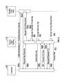
- FIG. 4illustrates an example of a diagram for a method to encrypt sensor data according to various embodiments.
- the diagram shown in FIG. 4may be referred to as the customer initiation procedure.
- the method shown in FIG. 4includes operations 401 - 410 in example embodiments.
- a customer 430makes a request to create a new customer key-pair.
- the new customer key-pairmay include a certified public key represented by the Customer Certificate 1100 .
- the customer 430may wish to create a new digital certificate and private key that implements a private key sharing scheme for data encryption.
- the requestis sent to the service data platform 140 .
- the service data platform 140generates the customer key-pair as shown by operation 402 .
- the service data platform 140synthesizes a new key-pair
- the customer 430generates the customer key-pair and provides the customer public key and possibly the customer private share (e.g., first share 140 a ) to the service data platform 140 .
- the customer private keymay be withheld by the customer 430 in which case the service data platform 140 may not be able to directly decrypt the customer's data.
- the service data platform 140sends a request 403 a to the certificate authority 102 as shown by operation 403 a .
- the certificate authority 102is part of the PKI 101 .
- the request at operation 403 amay be to request the certificate authority 102 to sign the customer pubic key.
- the certificate authorize 102returns the signature of the certificate authority 102 as part of digital certificate to the service data platform 140 .
- the signed digital certificaterepresents a certified customer public key.
- the certificate authority 102may provide Customer Certificates 1100 which are stored locally at the sensor nodes 100 a and a Customer Root Certificate 1000 , which is stored at the service data platform.
- the Customer Certificates 1100may be assigned to or distributed to the various sensor nodes 100 a or other devices within the sensor network 100 .
- the Customer Certificate 1100is used by the sensor nodes 100 a to encrypt sensor data or other data available to the sensor nodes 100 a.
- the service data platform 140may send a request (on behalf of the customer) to the certificate authority 102 to issue a key-pair and associated digital certificates, such as the Customer Certificate 1100 .
- the certificate authority 102then creates the key-pair and associated digital certificates and sends them back to the service data platform 140 .
- the service data platform 140distributes the Customer Certificates 110 representing the certified public keys from the customer key-pairs, to the customer devices (e.g., the sensor nodes 100 ) at operation 404 .
- the sensor nodes 100may represent the devices owned by the customer 430 .
- the public keyis included within the Customer Certificate 1100 in some embodiments.
- the signed Customer Certificate 1100is then returned to the customer who then distributes it to the devices that the customer owns. In some embodiments, if the customer has chosen to withhold the private key, no further action is taken.
- the reference numerals 405 and 406represent operations performed by the service data platform 140 .
- the private keyis split into multiple shares (e.g., three shares) by the service data platform 140 .
- the service data platform 140splits the private key into multiple shares using a private (or secret) sharing algorithm.
- the service data platform 140stores the server share on the service data platform 140 .
- the server shareis stored in plain text in a database in the service data platform 140 .
- the service data platform 140then transfers the third party share to the trusted third party 1031 .
- the third-party shareis securely transferred to the trusted third party device 103 for safe keeping or for use in offline decryption by the customer 430 .
- the service data platform 140sends a request for a password or passcode to the customer 430 that can be used to encrypt the customer share.
- the passcodemay be received from the customer 430 at operation 408 b .
- the customeris prompted for a password to encrypt the customer share.
- the service data platform 140encrypts the customer share of the private key and stores the password encrypted customer share of the private key in one of the database(s) 291 in the service data platform 140 .
- the service data platform 140may then return the customer share at operation 410 to the customer.
- the customer sharemay be encrypted or not encrypted.
- the customermay use the customer share received if the password encrypted customer share is lost, or may be used for encryption of the decrypted sensor data accessed from the service data platform 140 in combination with the trusted third party share, for example.
- the operation 401 , 403 a , 403 b , 408 a , 408 b , and 410may be performed by the communications module 146 .
- operations 404 and 407may be performed by the key distribution module 145 .
- the operation 402may be performed by the key-pair generation module 141 .
- the operations 405 and 406may be performed by the key sharing module 143 .
- the modules 146 , 145 , 141 , and 143are shown in FIG. 2 as part of the security system 144 .
- a methodfor protecting data available to sensor nodes 110 within a sensor network 100 .
- the methodincludes: generating a key-pair associated with a customer including a public encryption key and a private decryption key; requesting certification of the public encryption key; receiving a certificate representing a certified public encryption key; distributing the certificate to the sensor nodes within the sensor network 100 associated with the customer to enable the sensor nodes to encrypt sensor data available at the sensor nodes 110 with the certificate; splitting the private decryption key into multiple shares such that a designated subset of the multiple shares may be used in combination to enable a service data platform 140 to decrypt the encrypted sensor data; storing a first share 140 a of the multiple shares at the service data platform 140 ; storing a password encrypted local share of a second share 104 a of the multiple shares at the service data platform 140 ; and transmitting a third share 103 a of the multiple shares to a third-party device (e.g., the trusted third party device 103 ) for storage.
- the method for protecting data available to sensor nodes 110 within a sensor network 100includes receiving a request associated with the customer to generate the key-pair.
- the key-pairrepresents a customer key-pair.
- the method for protecting data available to sensor nodes 110 within a sensor network 100includes transmitting the second share 104 b of the multiple shares to a customer device 104 .
- the method for protecting data available to sensor nodes 110 within a sensor network 100includes destroying the private decryption key after splitting the private decryption key into multiple shares.
- the service data platform 140may implement various other security algorithms or schemes to provide added security to the sensor data collected at the sensor nodes 100 .
- the sensitive identification datamay be collected by at the sensor nodes 100 , which may include personally identifiable information and customer identifiable information. For example, camera, microphone or other data may be collected at the sensor nodes 100 .
- the sensor nodes 100may be bucket or group the sensor data into hourly or daily digests to remove time sensitivity. This protects against inferring content of the sensor data by monitoring the frequency of communications between the sensor nodes 100 and the service data platform 140 .
- the sensor nodes 100may pad (or adjust the size) of the sensor data to a fixed size to remove size sensitivity. This protects against inferring content of the data by monitoring the quantity of data sent to the server.
- the security algorithms or schemesmay be used alone or together with various embodiments of the public key cryptography described in this specification.
- the sensor data collected at the sensor nodes 100may be sent to the service data platform 140 over a secure connection.
- the service data platform 140stores the sensor data where it can be accessed by the customer in the future.
- a data packageis encrypted using the Customer Certificate 1100 .
- the data packagemay represent sensor data collected at the sensor nodes 100 that is to be transmitted to the service data platform 140 over a network (e.g., WAN 130 ).
- the encrypted data packetis combined with unencrypted metadata in a multipart payload, which is then signed using the Device Private Key 3201 .
- the signed multipart payloadmay be sent to the service data platform 140 over a secure connection.
- the service data platform 140sores the encrypted data package in one or more of database(s) 291 indexed by the unencrypted metadata keys so that the encrypted data package can be retrieved by the customer in the future.
- the service data platform 140may use a cryptographic hash of the signed payload as a content addressable file key.
- FIG. 5illustrates a diagram of a method for decrypting sensor data according to example embodiments.
- the service data platform 140is storing encrypted sensor data received from the sensor nodes 100 .
- the sensor datawas encrypted by the sensor nodes 100 and then transported to the service data platform 140 for storage.
- the customer 430sends a request to access the encrypted sensor data stored at the service data platform 140 .
- the customer 430logs into the service data platform 140 using its credentials (e.g., username and password).
- the customer 430may also request to view the sensor data that is encrypted using the customer certificate.
- the service data platform 140fetches the password protected encrypted local customer share and the server share.
- the service data platform 140obtains the encryption information from its database (e.g., database 291 ), including information on what Customer Certificate 1100 was used to encrypt the sensor data, the server share and the encrypted local share of the customer share.
- the service data platform 140sends a request for the encrypted local customer share password to the customer 430 .
- the service data platform 140receives the password from the customer 430 .
- the service data platform 140obtains the password for the encrypted local share from the customer 430 and decrypts the encrypted local customer share if the correct password is provided.
- the service data platform 140reconstructs the customer private key once the password is received. For example, where the private key sharing scheme uses three shares, each share includes at least two-thirds of the private key so the private key can be reconstructed with only two shares. Together, the decrypted local customer share and the server share are used to decrypt the encrypted sensor data stored at the service data platform 140 . The service data platform 140 retrieves the encrypted sensor data and then decrypts it at operation 505 .
- the service data platform 140provides a response that returns the decrypted sensor data to the customer 430 .
- the decrypted sensor datais transmitted to the customer's browser over a secure connection and rendered to the screen by the browser.
- operations 501 , 503 a , 503 b , and 506are performed by the communication module 146 .
- operations 502 and 504are performed by the key sharing module 143 .
- the operation 505may be performed by the security system 144 .
- the operation 505may be performed by a decryption module (not shown).
- the modules 146 , 143 , 144are shown in FIG. 2 .
- a method of protecting customer data in a networked systemincludes: collecting sensor data available at sensor nodes 110 within a sensor network 100 in communication with a service data platform 140 over a network (e.g., WAN 130 ); encrypting the sensor data using a certified public key associated with a customer key-pair, the sensor data representing the customer data associated with sensitive identification information; cryptographically signing the sensor data with a device private key; transporting the encrypted sensor data to the service data platform 140 for storage; and decrypting, at the service data platform 140 , the encrypted sensor data using a private key sharing scheme that reconstructs the private key associated with the customer key-pair using a first share 140 a and a password encrypted second share 104 a , the first share 140 a assigned to the service data platform 140 and the password encrypted second share 104 a assigned to a customer of the customer key-pair.
- the method of protecting customer data in a networked systemincludes: receiving a request associated with an authorized user of the customer of the service data platform 140 to access the encrypted sensor data stored by the service data platform 140 ; receiving a password associated with password encrypted second share 104 a ; and decrypting the password encrypted second share 104 a.
- the method of protecting customer data in a networked systemincludes combining the first share 140 a and the decrypted password encrypted second share 104 a to reconstruct the private key associated with the customer key-pair.
- the sensitive identification informationrepresents at one of customer identification information and personally identification information.
- the private key sharing schemeincludes at least three shares of the private key where at least two of the at least three shares may be used to reconstruct the private key associated with the customer key-pair for decrypting the encrypted sensor data.
- the customer 430chooses not to share their private key with the service data platform 140 to prevent the service data platform 140 from decrypting the encrypted sensor data stored at the service data platform 140 .
- the service data platform 140may be able to deliver the encrypted sensor data to the customer who can then decrypt the data offline. A method for decrypting sensor data offline from the service data platform 140 is described below.
- the method for decrypting sensor data offline from the service data platform 140may start with the customer 430 who logs into the service data platform 140 using its log in credentials such as user name and password.
- the customer 430then send a request to the service data platform 140 to access or retrieve the encrypted sensor data stored at the service data platform 140 .
- the encrypted sensor datamay be transported as a data package.
- the encrypted sensor data 140may be downloaded from the service data platform 140 by the customer 430 .
- the customer 430may then obtain the Device Root Certificate 3000 from the service data platform 140 .
- the customer 430is able to verify the signatures on the on the data package to ensure that the encrypted sensor data included in the data package is from the one or more of the customer's devices (e.g., sensor nodes 100 ). The customer 430 then decrypts sensor data using the customer's private key. If a private or secret sharing scheme is used, then the data package may be decrypted by a designated number of shares specified by the secret sharing scheme. The customer 430 may then view the decrypted sensor data using the customer's own tools and software applications.
- FIG. 6illustrates a diagram of a method for recovering a customer private key, according to various embodiments.
- the recovered customer private keyis associated with a first customer key-pair.
- a new customer private keyis created for a second customer key-pair.
- the key-pair generating module 141is used to generate the second customer key-pair
- the key recover module 142is used to recover the private key associated with the first customer key-pair when the customer's share is lost or no longer available to reconstruct the customer private key associated with the first customer key share.
- the key sharing module 143splits a customer private-key into multiple shares as required by the particular private key sharing scheme being implemented. The key-pair generating module 141 , the key recovery module 142 , and the key sharing module 143 are shown in FIG. 2 .
- the customer 430has used key sharing to protect itself against loss of the customer's share, or some other share of the private key issued to the customer (e.g., the second shares 104 a and 104 b .
- the customer share 104 b and the password for the encrypted local share of the customer's share 104 ahave been lost by the customer 430 .
- the service data platform 140may be requested to recover the lost data (associated with the customer's share of the private key associated with the first customer key-pair) with the help of the trusted third-party.
- the customer 430authorizes the trusted third-party device 103 to release the third party share 103 a to the service data platform 140 .
- a responsemay be provided by the trusted third party device 103 at operation 601 b that acknowledges this request.
- the customer 430requests that the service data platform 140 recover the lost key or key share (e.g., shares 104 a or 104 b ).
- the service data platform 140requests the third party share referred to as the third share 103 a from the trusted third party 1031 .
- third share 103 ais provided to the service data platform 140 by the trusted third party 1031 .
- the service data platform 140recovers the customer private key (associated with a first customer key-pair) by combining the third share 103 a and the server share represented by the first share 140 a.
- the private key associated with the first customer key-pairis reconstructed using two of the three shares from the private key sharing scheme.
- Each of the sharesincludes at least two-thirds of the customer private key from the first customer key-pair.
- the customercreates a new customer certificate and customer private key following the procedure or method outlined in FIG. 4 for generating a new key-pair.
- This procedure shown in FIG. 4may be referred to as the customer initiation procedure.
- the Customer Certificate 1100 and the customer private keyare associated with a second customer key-pair, referred to as the new key-pair.
- the private key sharing schemefor example as described in FIG. 5 , is used to split the customer private key associated with the second customer key-pair into multiple shares.
- an operation 605 bmay be used to provide the new private key associated with the second customer key-pair to the customer 430 .
- the shares of the new customer private keymay be distributed to the service data platform 140 , the sensor nodes 100 and the customer device 104 , as shown in FIG. 5 or FIGS. 3B-3D .
- the service data platform 140encrypts the recovered customer private key associated with the second customer key-pair with the new Customer Certificate 1100 and signs it with the Server Private Key 2200
- the encrypted recovered private key associated with first customer key-pairis stored in the database 291 .
- the new customer private keyis needed to decrypt it.
- the new customer private keyis reconstructed using the private sharing described above.
- the sensor nodes 100may encrypt sensor data using the Customer Certificate 1100 associated with the second customer key-pair. Such data can then be decrypted using the private key sharing scheme associated with the second customer key-pair. The sensor nodes 100 may also continue to encrypt sensor data using the Customer Certificate 1100 associated with the first customer key-pair.
- the recovered private key associated with the first customer key-pairis encrypted by the service data platform 140 and stored in one of its databases 291 to enable the customer 430 to decrypt data encrypted with the Customer Certificate 1100 associated with the first customer key-pair.
- the sensor nodes 110can continue to encrypt sensor data using the Customer Certificate 1100 from the first customer key-pair until the service data platform 140 distributes the Customer Certificate 1100 from the second customer key-pair to the sensor nodes 110 .
- the customer 430requests encrypted data stored on the service data platform 140 .
- the service data platform 140may stores both data encrypted with the Customer Certificate 1100 from the first customer key-pair 292 and data encrypted with the Customer Certificate 1100 from the second customer key-pair 293 .
- the data encrypted with the Customer Certificate 1100 from the first customer key-pairuses to the old (or recovered) key.
- the old (or recovered key)is used to decrypt the old data encrypted with the Customer Certificate 1100 associated with the first customer key-pair
- the service data platform 140checks to see if the sensor data was encrypted with a previously recovered key. If so, the service data platform 140 , prompts for the password of the new password encrypted local share of the customer share. Once the password for the second share 104 a is received, the service data platform 140 may decrypt the old private key.
- the service data platform 140decrypts the old private key which may be accessed from a database 292 .
- the recovered private key associated with the first customer key-pairmay be decrypted using the private key associated with the second customer key-pair.
- the private key associated with the second customer key-pairmay be reconstructed using the first share 140 a and the second share 104 a or 104 b associated with the second private key-pair.
- the decrypted sensor datamay be displayed to a customer or other authorized user of the customer.
- the operations 602 a , 602 b , 607 , 608 a , 608 b and 610may be performed by the communications module 146 .
- the operations 603 a and 603 b , and 604may be performed by the key recovery module 142 .
- the operation 605may be performed by the key-pair generation module 141 .
- the operation 606may be performed by the encryption module (not shown).
- the operation 609may be performed by the decryption module (not shown).
- the modules 146 , 142 , and 141are shown in FIG. 2 .
- method of protecting customer data in a networked systemincludes: receiving a request to access encrypted sensor data stored at a service data platform 140 ; determining the encrypted sensor data in the request was encrypted with a certified public key associated with a first customer key-pair, the first customer key-pair representing a recovered private key; determining the private key associated with the first customer key-pair is encrypted with the private key associated with a second customer key-pair; decrypting the private key associated with the first customer key-pair by using the private key associated with the second customer key-pair; and decrypting the encrypted sensor data in the request using the decrypted private key associated with the first customer key-pair.
- the networked systemincludes a sensor network 100 .
- the sensor network 100represents at least one of a Wi-Fi wireless network or an ad hoc wireless network.
- the method of protecting customer data in a networked systemincludes: collecting sensor data available at sensor nodes 110 within a sensor network 100 in communication with the service data platform 140 over a network (e.g., WAN 130 ); encrypting the sensor data using the certified public key associated with the first customer key-pair, the sensor data representing the customer data associated with sensitive identification information; cryptographically signing the sensor data using a device private key associated with the first customer key-pair; and transporting the encrypted sensor data to the service data platform 140 for storage.
- a networke.g., WAN 130
- the method of protecting customer data in a networked systemincludes: retrieving a third party share 103 a associated with the first customer key-pair authorized by the customer to provide to the service data platform 140 ; combining the third party share (e.g., third share 103 a ) associated with the first customer key-pair with a server share (e.g., first share 140 a ) assigned to the service data platform; and recovering the private key associated with the first customer key-pair using the server share (e.g., first share 140 a ) and the trusted third party share (e.g., third share 103 a ).
- a server sharee.g., first share 140 a
- the trusted third party sharee.g., third share 103 a
- the method of protecting customer data in a networked systemincludes: encrypting the recovered private key associated with the first customer key-pair; and storing the encrypted private key associated with the first customer key-pair at the service data platform 140 .
- the method of protecting customer data in a networked systemincludes: requesting a password for a password decrypted customer share (e.g., the second share 104 a ) of the private key associated with the second customer key-pair to reconstruct the private key associated with the second customer key-pair; receiving the password and decrypting the password decrypted customer share (e.g., the second share 104 a ) associated with the second customer key-pair; combining a server share (e.g., the first share 140 a ) and the decrypting password encrypted customer share (e.g., the second share 104 a ) associated with the second customer key-pair; and reconstructing the private key associated with the second customer key-pair.
- a server sharee.g., the first share 140 a
- the decrypting password encrypted customer sharee.g., the second share 104 a
- the method of protecting customer data in a networked systemincludes: encrypting the private key associated with the first customer key-pair by using a certified public key associated with the second customer key-pair; and storing the encrypted private key associated with the first customer key-pair.
- sensors 111that may be used in various embodiments in sensor nodes 100 include biometric sensors, motion sensors, environmental sensors and position sensors.
- the biometric sensorsmay include components to detect expressions (e.g., hand expressions, facial expressions, vocal expressions, body gestures, or eye tracking), measure bio signals (e.g., blood pressure, heart rate, body temperature, perspiration, or brain waves), identify a person (e.g., voice identification, retinal identification, facial identification, fingerprint identification, or electroencephalogram based identification), and the like.
- biometric sensorsmay include components to detect expressions (e.g., hand expressions, facial expressions, vocal expressions, body gestures, or eye tracking), measure bio signals (e.g., blood pressure, heart rate, body temperature, perspiration, or brain waves), identify a person (e.g., voice identification, retinal identification, facial identification, fingerprint identification, or electroencephalogram based identification), and the like.
- motions sensorsmay include motion components such as acceleration sensor components (e.g., accelerometer),
- environmental sensorsmay be used which include environmental components such as illumination sensor components (e.g., photometer), temperature sensor components (e.g., one or more thermometer that detect ambient temperature), humidity sensor components, pressure sensor components (e.g., barometer), acoustic sensor components (e.g., one or more microphones that detect background noise), proximity sensor components (e.g., infrared sensors that detect nearby objects), gas sensors (e.g., gas detection sensors to detection concentrations of hazardous gases for safety or to measure pollutants in the atmosphere), or other components that may provide indications, measurements, or signals corresponding to a surrounding physical environment.
- illumination sensor componentse.g., photometer
- temperature sensor componentse.g., one or more thermometer that detect ambient temperature
- humidity sensor componentse.g., pressure sensor components (e.g., barometer)
- acoustic sensor componentse.g., one or more microphones that detect background noise
- proximity sensor componentse.g., infrared sensors that detect nearby objects
- gas sensors
- Various positions sensorsmay include position components such as location sensor components (e.g., a Global Position System (GPS) receiver component), altitude sensor components (e.g., altimeters or barometers that detect air pressure from which altitude may be derived), orientation sensor components (e.g., magnetometers), and the like.
- location sensor componentse.g., a Global Position System (GPS) receiver component
- altitude sensor componentse.g., altimeters or barometers that detect air pressure from which altitude may be derived
- orientation sensor componentse.g., magnetometers
- modules, engines, components, or mechanismsmay be implemented as logic or a number of modules, engines, components, or mechanisms.
- a module, engine, logic, component, or mechanismmay be a tangible unit capable of performing certain operations and configured or arranged in a certain manner.
- one or more computer systemse.g., a standalone, client, or server computer system
- one or more components of a computer systeme.g., a processor or a group of processors
- softwaree.g., an application or application portion
- firmwarenote that software and firmware can generally be used interchangeably herein as is known by a skilled artisan
- a modulemay be implemented mechanically or electronically.
- a modulemay comprise dedicated circuitry or logic that is permanently configured (e.g., within a special-purpose processor, application specific integrated circuit (ASIC), or array) to perform certain operations.
- a modulemay also comprise programmable logic or circuitry (e.g., as encompassed within a general-purpose processor or other programmable processor) that is temporarily configured by software or firmware to perform certain operations. It will be appreciated that a decision to implement a module mechanically, in dedicated and permanently configured circuitry, or in temporarily configured circuitry (e.g., configured by software) may be driven by, for example, cost, time, energy-usage, and package size considerations.
- moduleshould be understood to encompass a tangible entity, be that an entity that is physically constructed, permanently configured (e.g., hardwired), or temporarily configured (e.g., programmed) to operate in a certain manner or to perform certain operations described herein.
- modules or componentsare temporarily configured (e.g., programmed)
- each of the modules or componentsneed not be configured or instantiated at any one instance in time.
- the modules or componentscomprise a general-purpose processor configured using software
- the general-purpose processormay be configured as respective different modules at different times.
- Softwaremay accordingly configure the processor to constitute a particular module at one instance of time and to constitute a different module at a different instance of time.
- Modulescan provide information to, and receive information from, other modules. Accordingly, the described modules may be regarded as being communicatively coupled. Where multiples of such modules exist contemporaneously, communications may be achieved through signal transmission (e.g., over appropriate circuits and buses) that connect the modules. In embodiments in which multiple modules are configured or instantiated at different times, communications between such modules may be achieved, for example, through the storage and retrieval of information in memory structures to which the multiple modules have access. For example, one module may perform an operation and store the output of that operation in a memory device to which it is communicatively coupled. A further module may then, at a later time, access the memory device to retrieve and process the stored output. Modules may also initiate communications with input or output devices and can operate on a resource (e.g., a collection of information).
- a resourcee.g., a collection of information
- an example embodimentextends to a machine in the example form of a computer system 700 within which instructions for causing the machine to perform any one or more of the methodologies discussed herein may be executed.
- the machineoperates as a standalone device or may be connected (e.g., networked) to other machines.
- the machinemay operate in the capacity of a server or a client machine in server-client network environment or n-tier network, as a peer machine in a peer-to-peer (or distributed) network environment or in a virtualized cloud computing environment.
- the machinemay be a personal computer (PC), wearable computing device, a tablet PC, a set-top box (STB), a Personal Digital Assistant (PDA), a cellular telephone, a web appliance, a network router, a switch or bridge, sensor node, or any machine capable of executing instructions (sequential or otherwise) that specify actions to be taken by that machine.
- PCpersonal computer
- PDAPersonal Digital Assistant
- STBset-top box
- a cellular telephonea web appliance
- network routera switch or bridge
- sensor nodeor any machine capable of executing instructions (sequential or otherwise) that specify actions to be taken by that machine.
- machineshall also be taken to include any collection of machines that individually or jointly execute a set (or multiple sets) of instructions to perform any one or more of the methodologies discussed herein.
- the example computer system 700may include a processor 702 (e.g., a central processing unit (CPU), a graphics processing unit (GPU) or both), a main memory 704 and a static memory 706 , which communicate with each other via a bus 708 .
- the computer system 700may further include a video display unit 710 (e.g., a liquid crystal display (LCD) or a cathode ray tube (CRT)).
- the computer system 700also includes one or more of an alpha-numeric input device 712 (e.g., a keyboard), a user interface (UI) navigation device or cursor control device 714 (e.g., a mouse), a storage unit 716 , a signal generation device 718 (e.g., a speaker), and a network interface device 720 .
- an alpha-numeric input device 712e.g., a keyboard
- UIuser interface
- cursor control device 714e.g., a mouse
- the storage unit 716includes a machine-readable storage medium 722 on which is stored one or more sets of instructions 724 and data structures (e.g., software instructions) embodying or used by any one or more of the methodologies or functions described herein.
- the instructions 724may also reside, completely or at least partially, within the main memory 704 or within the processor 702 during execution thereof by the computer system 700 , with the main memory 704 and the processor 702 also constituting machine-readable media.
- machine-readable storage medium 722is shown in an example embodiment to be a single medium, the term “machine-readable storage medium” may include a single medium or multiple media (e.g., a centralized or distributed database, or associated caches and servers) that store the one or more instructions.
- the term “machine-readable medium”shall also be taken to include any tangible medium that is capable of storing, encoding, or carrying instructions for execution by the machine and that cause the machine to perform any one or more of the methodologies of embodiments of the present invention, or that is capable of storing, encoding, or carrying data structures used by or associated with such instructions.
- the term “machine-readable storage medium”shall accordingly be taken to include, but not be limited to, solid-state memories and optical and magnetic media.
- machine-readable storage mediainclude non-volatile memory, including by way of example semiconductor memory devices (e.g., Erasable Programmable Read-Only Memory (EPROM), Electrically Erasable Programmable Read-Only Memory (EEPROM), and flash memory devices); magnetic disks such as internal hard disks and removable disks; magneto-optical disks; and CD-ROM and DVD-ROM disks.
- semiconductor memory devicese.g., Erasable Programmable Read-Only Memory (EPROM), Electrically Erasable Programmable Read-Only Memory (EEPROM), and flash memory devices
- EPROMErasable Programmable Read-Only Memory
- EEPROMElectrically Erasable Programmable Read-Only Memory
- flash memory devicese.g., Electrically Erasable Programmable Read-Only Memory (EEPROM), and flash memory devices
- magnetic diskssuch as internal hard disks and removable disks
- magneto-optical disksmagneto-optical disks
- CD-ROM and DVD-ROM disksCD-ROM
- the instructions 724may further be transmitted or received over a communications network 726 using a transmission medium via the network interface device 720 and utilizing any one of a number of well-known transfer protocols (e.g., HTTP).
- Examples of communication networksinclude a local area network (LAN), a wide area network (WAN), the Internet, mobile telephone networks, POTS networks, and wireless data networks (e.g., Wi-Fi and WiMAX networks).
- the term “transmission medium”shall be taken to include any intangible medium that is capable of storing, encoding, or carrying instructions for execution by the machine, and includes digital or analog communications signals or other intangible medium to facilitate communication of such software.
- inventive subject matterhas been described with reference to specific example embodiments, various modifications and changes may be made to these embodiments without departing from the broader spirit and scope of embodiments of the present invention.
- inventive subject mattermay be referred to herein, individually or collectively, by the term “invention” merely for convenience and without intending to voluntarily limit the scope of this application to any single invention or inventive concept if more than one is, in fact, disclosed.
Landscapes
- Engineering & Computer Science (AREA)
- Computer Security & Cryptography (AREA)
- Computer Networks & Wireless Communication (AREA)
- Signal Processing (AREA)
- Theoretical Computer Science (AREA)
- Business, Economics & Management (AREA)
- General Physics & Mathematics (AREA)
- Physics & Mathematics (AREA)
- Computer Hardware Design (AREA)
- General Engineering & Computer Science (AREA)
- Strategic Management (AREA)
- Software Systems (AREA)
- Computing Systems (AREA)
- Economics (AREA)
- General Business, Economics & Management (AREA)
- General Health & Medical Sciences (AREA)
- Health & Medical Sciences (AREA)
- Entrepreneurship & Innovation (AREA)
- Marketing (AREA)
- Development Economics (AREA)
- Accounting & Taxation (AREA)
- Finance (AREA)
- Bioethics (AREA)
- Operations Research (AREA)
- Quality & Reliability (AREA)
- Tourism & Hospitality (AREA)
- Human Resources & Organizations (AREA)
- Game Theory and Decision Science (AREA)
- Medical Informatics (AREA)
- Telephonic Communication Services (AREA)
- Selective Calling Equipment (AREA)
- Mobile Radio Communication Systems (AREA)
- Storage Device Security (AREA)
Abstract
Description
- a trusted party, also referred to as a certificate authority, who acts as the root of trust and provides services that authenticate the identity of individuals, computers and other entities;
- a registration authority, also referred to as a subordinate certificate authority, is certified by a root certificate authority to issue digital certificates for specific uses permitted by the root;
- a certificate database for storing certificate requests; and
- a certificate store, which may reside on a local computer as a place to store issued certificates and private keys.
In some embodiments, thePKI 101 may be a private PKI owned and operated by theservice data provider 140.
Claims (16)
Priority Applications (7)
| Application Number | Priority Date | Filing Date | Title |
|---|---|---|---|
| US14/639,841US9582671B2 (en) | 2014-03-06 | 2015-03-05 | Security and data privacy for lighting sensory networks |
| PCT/US2015/019286WO2015134929A2 (en) | 2014-03-06 | 2015-03-06 | Security and data privacy for lighting sensor networks |
| KR1020167026986AKR20170015280A (en) | 2014-03-06 | 2015-03-06 | Security and data privacy for lighting sensor networks |
| JP2016573714AJP2017507629A (en) | 2014-03-06 | 2015-03-06 | Security and data privacy for lighting sensor networks |
| EP15758966.4AEP3111585B1 (en) | 2014-03-06 | 2015-03-06 | Security and data privacy for lighting sensor networks |
| CN201580022751.6ACN106797310B (en) | 2014-03-06 | 2015-03-06 | Method and system for protecting customer data in a networked system |
| US15/387,234US9959413B2 (en) | 2012-09-12 | 2016-12-21 | Security and data privacy for lighting sensory networks |
Applications Claiming Priority (2)
| Application Number | Priority Date | Filing Date | Title |
|---|---|---|---|
| US201461948817P | 2014-03-06 | 2014-03-06 | |
| US14/639,841US9582671B2 (en) | 2014-03-06 | 2015-03-05 | Security and data privacy for lighting sensory networks |
Related Parent Applications (1)
| Application Number | Title | Priority Date | Filing Date |
|---|---|---|---|
| US14/024,561ContinuationUS9374870B2 (en) | 2012-09-12 | 2013-09-11 | Networked lighting infrastructure for sensing applications |
Related Child Applications (1)
| Application Number | Title | Priority Date | Filing Date |
|---|---|---|---|
| US15/387,234DivisionUS9959413B2 (en) | 2012-09-12 | 2016-12-21 | Security and data privacy for lighting sensory networks |
Publications (2)
| Publication Number | Publication Date |
|---|---|
| US20150254463A1 US20150254463A1 (en) | 2015-09-10 |
| US9582671B2true US9582671B2 (en) | 2017-02-28 |
Family
ID=54017637
Family Applications (2)
| Application Number | Title | Priority Date | Filing Date |
|---|---|---|---|
| US14/639,841Expired - Fee RelatedUS9582671B2 (en) | 2012-09-12 | 2015-03-05 | Security and data privacy for lighting sensory networks |
| US15/387,234ActiveUS9959413B2 (en) | 2012-09-12 | 2016-12-21 | Security and data privacy for lighting sensory networks |
Family Applications After (1)
| Application Number | Title | Priority Date | Filing Date |
|---|---|---|---|
| US15/387,234ActiveUS9959413B2 (en) | 2012-09-12 | 2016-12-21 | Security and data privacy for lighting sensory networks |
Country Status (6)
| Country | Link |
|---|---|
| US (2) | US9582671B2 (en) |
| EP (1) | EP3111585B1 (en) |
| JP (1) | JP2017507629A (en) |
| KR (1) | KR20170015280A (en) |
| CN (1) | CN106797310B (en) |
| WO (1) | WO2015134929A2 (en) |
Cited By (3)
| Publication number | Priority date | Publication date | Assignee | Title |
|---|---|---|---|---|
| US20190342080A1 (en)* | 2018-05-01 | 2019-11-07 | Huawei Technologies Co., Ltd. | Systems, Devices, and Methods for Hybrid Secret Sharing |
| US20250045736A1 (en)* | 2023-08-01 | 2025-02-06 | Circle Internet Group, Inc. | End-user controlled wallets in blockchain systems |
| US20250045743A1 (en)* | 2023-08-01 | 2025-02-06 | Circle Internet Group, Inc. | Platform controlled wallets in blockchain systems |
Families Citing this family (63)
| Publication number | Priority date | Publication date | Assignee | Title |
|---|---|---|---|---|
| JP6386217B2 (en) | 2012-09-12 | 2018-09-05 | センシティ システムズ インコーポレイテッド | Networked lighting infrastructure for sensing applications |
| US9582671B2 (en) | 2014-03-06 | 2017-02-28 | Sensity Systems Inc. | Security and data privacy for lighting sensory networks |
| US9500739B2 (en) | 2014-03-28 | 2016-11-22 | Knowles Electronics, Llc | Estimating and tracking multiple attributes of multiple objects from multi-sensor data |
| US9558377B2 (en)* | 2015-01-07 | 2017-01-31 | WaveLynx Technologies Corporation | Electronic access control systems including pass-through credential communication devices and methods for modifying electronic access control systems to include pass-through credential communication devices |
| CN106302312B (en)* | 2015-05-13 | 2019-09-17 | 阿里巴巴集团控股有限公司 | Obtain the method and device of electronic document |
| CN108432277B (en) | 2015-11-03 | 2022-06-10 | 诺基亚技术有限公司 | Device and method for privacy protection |
| CN116957790A (en) | 2016-02-23 | 2023-10-27 | 区块链控股有限公司 | Method and system for realizing universal certification of exchange on blockchain |
| AU2017223138B2 (en) | 2016-02-23 | 2022-02-10 | nChain Holdings Limited | Method and system for efficient transfer of cryptocurrency associated with a payroll on a blockchain that leads to an automated payroll method and system based on smart contracts |
| BR112018016821A2 (en) | 2016-02-23 | 2018-12-26 | Nchain Holdings Ltd | computer-implemented system and methods |
| CN115641131A (en) | 2016-02-23 | 2023-01-24 | 区块链控股有限公司 | Method and system for secure transfer of entities over a blockchain |
| CN108292402B (en) | 2016-02-23 | 2022-10-04 | 恩链控股有限公司 | Determination of a common secret and hierarchical deterministic keys for the secure exchange of information |
| BR112018016819A2 (en) | 2016-02-23 | 2018-12-26 | Nchain Holdings Ltd | method and systems for protecting a controlled digital resource using a distributed scatter table and ledger and a blockchain |
| EP3748903A1 (en) | 2016-02-23 | 2020-12-09 | Nchain Holdings Limited | Universal tokenisation system for blockchain-based cryptocurrencies |
| MX2018010050A (en) | 2016-02-23 | 2019-01-21 | Nchain Holdings Ltd | Agent-based turing complete transactions integrating feedback within a blockchain system. |
| BR112018016234A2 (en)* | 2016-02-23 | 2019-01-02 | Nchain Holdings Ltd | computer-implemented method for controlling access to a resource, computer-based systems and method for controlling access to a digital wallet |
| JP6511201B1 (en) | 2016-02-23 | 2019-05-15 | エヌチェーン ホールディングス リミテッドNchain Holdings Limited | Registry and Automated Management Method for Sophisticated Trading Enforced by Blockchain |
| IL261210B (en) | 2016-02-23 | 2022-08-01 | Nchain Holdings Ltd | An exchange based on a 'block chain' with tokenization |
| GB2562622A (en) | 2016-02-23 | 2018-11-21 | Nchain Holdings Ltd | Cryptographic method and system for secure extraction of data from a blockchain |
| EP4235552A3 (en) | 2016-02-23 | 2023-09-13 | nChain Licensing AG | Methods and systems for efficient transfer of entities on a peer-to-peer distributed ledger using the blockchain |
| MX2018010052A (en) | 2016-02-23 | 2019-01-21 | Nchain Holdings Ltd | System and method for controlling asset-related actions via a blockchain. |
| SG11201806702XA (en) | 2016-02-23 | 2018-09-27 | Nchain Holdings Ltd | Personal device security using elliptic curve cryptography for secret sharing |
| AT518298B1 (en)* | 2016-03-07 | 2020-01-15 | Avl List Gmbh | Method for creating and updating a remote instance of a screen view |
| US10609011B2 (en)* | 2016-03-25 | 2020-03-31 | Ca, Inc. | Synchronized issuance of public X.509 digital certificates |
| US10341309B1 (en) | 2016-06-13 | 2019-07-02 | Allstate Insurance Company | Cryptographically protecting data transferred between spatially distributed computing devices using an intermediary database |
| US20170359343A1 (en)* | 2016-06-14 | 2017-12-14 | Comfylight Ag | System and method for secure communications with internet-of-things devices |
| US11251957B2 (en)* | 2016-06-28 | 2022-02-15 | Robert Bosch Gmbh | System and method for delegating ticket authentication to a star network in the internet of things and services |
| CN107666386B (en)* | 2016-07-27 | 2021-05-28 | 复凌科技(上海)有限公司 | Data secure transmission method and device |
| KR101880708B1 (en)* | 2016-08-16 | 2018-07-20 | (주)샌코 | DATA TRANSFER SYSTEM OF DEVICE IN IoT HAVING IMPROVED SECURITY |
| WO2018046103A1 (en)* | 2016-09-10 | 2018-03-15 | Swiss Reinsurance Company Ltd. | Secure key management and peer-to-peer transmission system with a controlled, double-tier cryptographic key structure and corresponding method thereof |
| DE102017102712A1 (en)* | 2017-02-10 | 2018-08-16 | Schréder S.A. | Decentralized data storage |
| US10546145B2 (en)* | 2017-02-17 | 2020-01-28 | International Business Machines Corporation | Storing data from a sensor device into a neighboring device |
| JP6910824B2 (en)* | 2017-03-28 | 2021-07-28 | Necネッツエスアイ株式会社 | Information provision system and information provision method |
| GB201709367D0 (en)* | 2017-06-13 | 2017-07-26 | Nchain Holdings Ltd | Computer-implemented system and method |
| GB201710176D0 (en)* | 2017-06-26 | 2017-08-09 | Nchain Holdings Ltd | Computer-implemented system and method |
| US9998895B1 (en)* | 2017-06-28 | 2018-06-12 | Motorola Solutions, Inc. | Apparatus and method for real-time public safety evidentiary data collection |
| US10306341B2 (en) | 2017-06-28 | 2019-05-28 | Motorola Solutions, Inc. | Method and apparatus for determining sensor data reliability at an incident scene for real-time and post-incident processing |
| WO2019005175A1 (en) | 2017-06-30 | 2019-01-03 | Intel Corporation | Magnetoelectric spin orbit logic with displacement charge |
| WO2019005098A1 (en) | 2017-06-30 | 2019-01-03 | Go Logic Decision Time, Llc | Methods and systems of assertional projective simulation |
| US10476855B1 (en)* | 2017-08-29 | 2019-11-12 | Salesforce.Com, Inc. | Identity confirmation using private keys |
| US10652224B2 (en)* | 2017-12-05 | 2020-05-12 | International Business Machines Corporation | Stateless session synchronization between secure communication interceptors |
| EP3740919A4 (en)* | 2018-01-17 | 2021-11-10 | tZERO IP, LLC | MULTIPLE APPROVAL SYSTEM WITH M OF N KEYS TO RECOVER A CUSTOMER'S WALLET |
| US12160530B2 (en)* | 2018-05-07 | 2024-12-03 | Sony Corporation | Communication terminal, sensing device, and server |
| CN112753033B (en)* | 2018-09-18 | 2024-02-09 | 西门子能源环球有限责任两合公司 | Sensor control components and manufacturing equipment |
| WO2020076722A1 (en) | 2018-10-12 | 2020-04-16 | Medici Ventures, Inc. | Encrypted asset encryption key parts allowing for assembly of an asset encryption key using a subset of the encrypted asset encryption key parts |
| US11038878B2 (en)* | 2019-03-14 | 2021-06-15 | Hector Hoyos | Computer system security using a biometric authentication gateway for user service access with a divided and distributed private encryption key |
| JP2020167509A (en)* | 2019-03-29 | 2020-10-08 | コベルコ建機株式会社 | Information processing system, information processing method, and program |
| US11321491B2 (en)* | 2019-07-24 | 2022-05-03 | Faro Technologies, Inc. | Tracking data acquired by coordinate measurement devices through a workflow |
| US11927948B2 (en)* | 2019-09-26 | 2024-03-12 | Signify Holding, B.V. | Presenting a current status of a device in dependence on a privacy mode |
| CN110704856B (en)* | 2019-10-09 | 2021-08-20 | 成都安恒信息技术有限公司 | Secret sharing method based on operation and maintenance auditing system |
| US11423171B2 (en)* | 2019-12-23 | 2022-08-23 | Intel Corporation | Protection of privacy and data on smart edge devices |
| JP6997821B2 (en)* | 2020-03-09 | 2022-01-18 | 三菱電機インフォメーションシステムズ株式会社 | Decryption system |
| US11405200B1 (en) | 2020-05-21 | 2022-08-02 | Workday, Inc. | Multilevel split keys for wallet recovery |
| US11870898B2 (en)* | 2020-05-21 | 2024-01-09 | Workday, Inc. | Split keys for wallet recovery |
| GB202009728D0 (en)* | 2020-06-25 | 2020-08-12 | British Telecomm | Secure communication of user device data |
| CN112257089A (en)* | 2020-10-28 | 2021-01-22 | 衡阳圣堂科技有限公司 | Automatic storage system for customer information |
| US20220176903A1 (en)* | 2020-12-03 | 2022-06-09 | Sidewalk Labs LLC | Wireless occupancy sensors and methods for using the same |
| US11956324B2 (en)* | 2021-01-07 | 2024-04-09 | Stmicroelectronics S.R.L. | Sensor device, system and method |
| EP4047899A1 (en)* | 2021-02-19 | 2022-08-24 | Nagravision S.A. | Methods and systems for controlling access to sensor data |
| US12177195B2 (en)* | 2021-06-14 | 2024-12-24 | Drkumo Inc. | Network transport independent encrypted sensor data transport system and methods |
| US11522958B1 (en) | 2021-12-12 | 2022-12-06 | Intrado Life & Safety, Inc. | Safety network of things |
| US11522703B1 (en) | 2022-01-19 | 2022-12-06 | Vignet Incorporated | Decentralized applications and data sharing platform for clinical research |
| US12299168B2 (en)* | 2022-12-01 | 2025-05-13 | Sap Se | Automatic generation of implicit information |
| CN118470647B (en)* | 2024-07-09 | 2024-11-15 | 宁波永耀电力投资集团有限公司 | Electric power monitoring method and system based on digital twin technology |
Citations (158)
| Publication number | Priority date | Publication date | Assignee | Title |
|---|---|---|---|---|
| US4384288A (en) | 1980-12-31 | 1983-05-17 | Walton Charles A | Portable radio frequency emitting identifier |
| US5161107A (en) | 1990-10-25 | 1992-11-03 | Mestech Creation Corporation | Traffic surveillance system |
| US5161607A (en) | 1991-08-19 | 1992-11-10 | Chao Wen Hua | Thermal storage device for interacting with a circulating coolant in an air conditioning system |
| US5793491A (en) | 1992-12-30 | 1998-08-11 | Schwartz Electro-Optics, Inc. | Intelligent vehicle highway system multi-lane sensor and method |
| US6118230A (en) | 1998-01-30 | 2000-09-12 | Hewlett-Packard Company | Lighting control system including server for receiving and processing lighting control requests |
| US6364253B1 (en) | 2000-04-25 | 2002-04-02 | The United States Of America As Represented By The Secretary Of The Navy | Remote piloted vehicle powered by beamed radiation |
| US20020195975A1 (en) | 2001-03-13 | 2002-12-26 | Schanberger Eric K. | Systems and methods for synchronizing lighting effects |
| US20030102979A1 (en) | 1995-07-03 | 2003-06-05 | Thomas C. Jednacz | Lighting control system with packet hopping communication |
| WO2003055734A1 (en) | 2001-12-27 | 2003-07-10 | Koninklijke Philips Electronics N.V. | Computer vision based parking assistant |
| US6608453B2 (en) | 1997-08-26 | 2003-08-19 | Color Kinetics Incorporated | Methods and apparatus for controlling devices in a networked lighting system |
| US20030222587A1 (en) | 1997-08-26 | 2003-12-04 | Color Kinetics, Inc. | Universal lighting network methods and systems |
| US6696945B1 (en) | 2001-10-09 | 2004-02-24 | Diamondback Vision, Inc. | Video tripwire |
| US20040124338A1 (en) | 2002-12-31 | 2004-07-01 | Serge Cloutier | Distributed dimmable lighting control system and method |
| US6961313B1 (en) | 2000-11-29 | 2005-11-01 | Advanced Micro Devices, Inc. | Arrangement for verifying randomness of TBEB algorithm in a media access controller |
| US6970083B2 (en) | 2001-10-09 | 2005-11-29 | Objectvideo, Inc. | Video tripwire |
| US20050285547A1 (en) | 1997-08-26 | 2005-12-29 | Color Kinetics Incorporated | Light emitting diode based products |
| US6999882B2 (en) | 2002-07-29 | 2006-02-14 | Siemens Aktiengellschaft | Method for determining a mass airflow |
| EP1658579A1 (en) | 2003-08-15 | 2006-05-24 | Scape A/S | Computer-vision system for classification and spatial localization of bounded 3d-objects |
| KR20070044243A (en) | 2005-10-24 | 2007-04-27 | 주식회사 케이티 | Urban control street light system and its method |
| US20070143608A1 (en)* | 2005-09-21 | 2007-06-21 | Nec (China) Co., Ltd. | Malleable pseudonym certificate system and method |
| KR100760535B1 (en) | 2006-10-30 | 2007-09-20 | 에스케이 텔레콤주식회사 | Ubiquitous Sensor Network System Using Mobile Communication Network and Sensor Information Transmission Method in the System |
| US20070223706A1 (en)* | 2005-12-12 | 2007-09-27 | Alexander Gantman | Certify and split system and method for replacing cryptographic keys |
| US20070234036A1 (en) | 2006-03-30 | 2007-10-04 | Tan Tat K | Network mobility node authentication |
| US20070258585A1 (en) | 2006-05-05 | 2007-11-08 | Tricipher, Inc. | Multifactor split asymmetric crypto-key with persistent key security |
| US7304727B2 (en) | 2005-05-25 | 2007-12-04 | Asia Optical Co., Inc. | Laser distance-measuring device |
| KR100784836B1 (en) | 2007-06-14 | 2007-12-14 | 주식회사 이너스텍 | U-city type columnar network system using Zigbee |
| US20070294393A1 (en) | 2006-05-18 | 2007-12-20 | Harris Corporation | Method and system for functional redundancy based quality of service |
| WO2008008505A2 (en) | 2006-07-14 | 2008-01-17 | Objectvideo, Inc. | Video analytics for retail business process monitoring |
| US7333903B2 (en) | 2005-09-12 | 2008-02-19 | Acuity Brands, Inc. | Light management system having networked intelligent luminaire managers with enhanced diagnostics capabilities |
| WO2008085815A1 (en) | 2007-01-05 | 2008-07-17 | Objectvideo, Inc. | Video-based sensing for lighting controls |
| CA2690148A1 (en) | 2007-06-09 | 2008-12-18 | Sensormatic Electronics Corporation | System and method for integrating video analytics and data analytics/mining |
| US20090026966A1 (en) | 2006-03-07 | 2009-01-29 | Koninklijke Philips Electronics N V | Lighting system with lighting units using optical communication |
| US20090066540A1 (en) | 2007-09-07 | 2009-03-12 | Dimitri Marinakis | Centralized route calculation for a multi-hop streetlight network |
| WO2009076182A1 (en) | 2007-12-13 | 2009-06-18 | Clemson University | Vision based real time traffic monitoring |
| US7583815B2 (en) | 2005-04-05 | 2009-09-01 | Objectvideo Inc. | Wide-area site-based video surveillance system |
| US20090218951A1 (en) | 2008-03-02 | 2009-09-03 | Mpj Lighting, Llc | Lighting and control systems and methods |
| US20090262189A1 (en) | 2008-04-16 | 2009-10-22 | Videoiq, Inc. | Energy savings and improved security through intelligent lighting systems |
| US7613324B2 (en) | 2005-06-24 | 2009-11-03 | ObjectVideo, Inc | Detection of change in posture in video |
| US7613590B2 (en) | 1992-11-17 | 2009-11-03 | Health Hero Network, Inc. | Modular microprocessor-based power tool system |
| US20090278479A1 (en) | 2008-05-06 | 2009-11-12 | Platner Brian P | Networked, wireless lighting control system with distributed intelligence |
| US20090299527A1 (en) | 2008-06-02 | 2009-12-03 | Adura Technologies, Inc. | Distributed intelligence in lighting control |
| US20090307255A1 (en) | 2008-06-06 | 2009-12-10 | Johnson Controls Technology Company | Graphical management of building devices |
| US20100001652A1 (en) | 2006-09-11 | 2010-01-07 | Jan Willy Damsleth | Control device, system and method for public illumination |
| US20100037055A1 (en)* | 2008-08-11 | 2010-02-11 | International Business Machines Corporation | Method For Authenticated Communication In Dynamic Federated Environments |
| US7674018B2 (en) | 2006-02-27 | 2010-03-09 | Illumination Management Solutions Inc. | LED device for wide beam generation |
| US20100204847A1 (en) | 2009-02-10 | 2010-08-12 | Leete Iii Lawrence F | Wireless infrastructure mesh network system using a lighting node |
| US20100228601A1 (en) | 2008-10-01 | 2010-09-09 | Silver Spring Networks, Inc. | Method and System of Applying Environmental Incentives |
| US20100235588A1 (en)* | 2007-02-16 | 2010-09-16 | Manabu Maeda | Shared information distributing device, holding device, certificate authority device, and system |
| US7817063B2 (en) | 2005-10-05 | 2010-10-19 | Abl Ip Holding Llc | Method and system for remotely monitoring and controlling field devices with a street lamp elevated mesh network |
| US7825602B2 (en) | 2007-06-29 | 2010-11-02 | Foxisemicon Integrated Technology, Inc. | Outdoor lighting system with controlled luminance |
| KR20100136186A (en) | 2009-06-18 | 2010-12-28 | (주)와이즈랩 | LED street light control method and apparatus |
| US20110002324A1 (en) | 2008-03-11 | 2011-01-06 | Koninklijke Philips Electronics N.V. | Time synchronization of a plurality of different wireless networks with data sensors |
| US7868912B2 (en) | 2000-10-24 | 2011-01-11 | Objectvideo, Inc. | Video surveillance system employing video primitives |
| KR20110017037A (en) | 2009-08-13 | 2011-02-21 | 유빈스 주식회사 | Wireless Sensor Street Light Control System Using Ubiquitous Sensor Network and Its Method |
| US20110066297A1 (en) | 2008-05-20 | 2011-03-17 | LiveMeters, Inc. | Remote monitoring and control system comprising mesh and time synchronization technology |
| US7925384B2 (en) | 2008-06-02 | 2011-04-12 | Adura Technologies, Inc. | Location-based provisioning of wireless control systems |
| US7925249B2 (en) | 2004-09-20 | 2011-04-12 | Robert Bosch Gmbh | Secure control of a wireless sensor network via the internet |
| WO2011041903A1 (en) | 2009-10-07 | 2011-04-14 | Telewatch Inc. | Video analytics with pre-processing at the source end |
| US7932923B2 (en) | 2000-10-24 | 2011-04-26 | Objectvideo, Inc. | Video surveillance system employing video primitives |
| US20110103583A1 (en)* | 2009-10-29 | 2011-05-05 | Korea Internet & Security Agency | Method and system for preserving security of sensor data and recording medium using thereof |
| WO2011053969A2 (en) | 2009-11-02 | 2011-05-05 | Infinity Laser Measuring Llc | Laser measurement of a vehicle frame |
| WO2011055261A1 (en) | 2009-11-03 | 2011-05-12 | Koninklijke Philips Electronics N.V. | Object-sensing lighting network and control system therefor |
| KR20110055807A (en) | 2009-11-20 | 2011-05-26 | 삼성에스디에스 주식회사 | Lighting control system based on wireless communication and control method thereof |
| US20110133655A1 (en) | 2006-03-28 | 2011-06-09 | Recker Michael V | Autonomous grid shifting lighting device |
| US20110158410A1 (en) | 2008-09-10 | 2011-06-30 | Rainer Falk | Method for transmitting data between network nodes |
| US7983685B2 (en) | 2006-12-07 | 2011-07-19 | Innovative Wireless Technologies, Inc. | Method and apparatus for management of a global wireless sensor network |
| US7986339B2 (en) | 2003-06-12 | 2011-07-26 | Redflex Traffic Systems Pty Ltd | Automated traffic violation monitoring and reporting system with combined video and still-image data |
| US20110197061A1 (en)* | 2009-08-12 | 2011-08-11 | General Instrument Corporation | Configurable online public key infrastructure (pki) management framework |
| US20110199004A1 (en) | 2010-02-18 | 2011-08-18 | Redwood Systems, Inc. | Commissioning lighting systems |
| US8027809B2 (en) | 1992-11-17 | 2011-09-27 | Health Hero Network, Inc. | Home power management system |
| WO2011121470A1 (en) | 2010-03-29 | 2011-10-06 | Koninklijke Philips Electronics N.V. | Network of heterogeneous devices including at least one outdoor lighting fixture node |
| WO2011132013A1 (en) | 2010-04-23 | 2011-10-27 | Nokia Corporation | Method and apparatus for transfer of radio resource allocation |
| US8049592B2 (en) | 2007-07-06 | 2011-11-01 | Chunghwa Telecom Co., Ltd. | Network-based lighting equipment remote monitoring and management system |
| US8073554B2 (en) | 2006-12-20 | 2011-12-06 | Nortel Networks Limited | System and method for providing power management in a sensor network |
| US8078431B2 (en) | 1992-11-17 | 2011-12-13 | Health Hero Network, Inc. | Home power management system |
| US20110309756A1 (en) | 2010-06-17 | 2011-12-22 | Ren-Cheng Chao | Road Lamp Dimming Control Device |
| US20120002406A1 (en) | 2010-06-30 | 2012-01-05 | Kevin Franklin Leadford | Slidable luminaire connectors |
| US8095340B2 (en) | 1992-11-17 | 2012-01-10 | Health Hero Network, Inc. | Home power management system |
| US20120008787A1 (en) | 2007-05-22 | 2012-01-12 | Chieh-Yih Wan | Lightweight key distribution and management method for sensor networks |
| US8111018B2 (en) | 2008-12-30 | 2012-02-07 | Evercomm Opto Ltd. | Application infrastructure for constructing illumination equipments with networking capability |
| US20120036362A1 (en) | 2010-08-05 | 2012-02-09 | International Business Machines Corporation | Secret-Key Exchange for Wireless and Sensor Networks |
| US20120038281A1 (en) | 2007-06-29 | 2012-02-16 | Orion Energy Systems, Inc. | Outdoor lighting fixtures control systems and methods |
| US20120040606A1 (en) | 2007-06-29 | 2012-02-16 | Orion Energy Systems, Inc. | Outdoor lighting systems and methods for wireless network communications |
| US20120043889A1 (en) | 2006-03-28 | 2012-02-23 | Wireless Environment, Llc. | Off-Grid LED Power Failure Lights |
| US20120062123A1 (en) | 2010-09-09 | 2012-03-15 | Jarrell John A | Managing Light System Energy Use |
| US20120068608A1 (en) | 2010-09-17 | 2012-03-22 | Redwood Systems, Inc. | Color and position auto-commissioning |
| US8147267B2 (en) | 2010-09-02 | 2012-04-03 | Xeralux, Inc. | Base for retrofit LED lighting device |
| WO2012042432A1 (en) | 2010-10-01 | 2012-04-05 | Koninklijke Philips Electronics N.V. | Device and method for scheduling data packet transmissions in wireless networks |
| US20120086561A1 (en) | 2010-10-07 | 2012-04-12 | General Electric Company | Outdoor lighting system |
| US20120130774A1 (en) | 2010-11-18 | 2012-05-24 | Dror Daniel Ziv | Analyzing performance using video analytics |
| US20120130544A1 (en) | 2008-09-10 | 2012-05-24 | Enlighted, Inc. | Logical Groupings of Intelligent Building Fixtures |
| US20120143357A1 (en) | 2010-11-04 | 2012-06-07 | Digital Lumens, Inc. | Method, apparatus, and system for occupancy sensing |
| US20120146518A1 (en) | 2010-12-13 | 2012-06-14 | Mark Keating | Predicative lighting control system |
| WO2012092150A2 (en) | 2010-12-30 | 2012-07-05 | Pelco Inc. | Inference engine for video analytics metadata-based event detection and forensic search |
| US20120191770A1 (en) | 2009-02-16 | 2012-07-26 | Amiram Perlmutter | System, a method and a computer program product for automated remote control |
| US8285986B2 (en) | 2008-10-02 | 2012-10-09 | Samsung Electronics Co., Ltd | Apparatus and method for data packet security in a wireless sensor network |
| WO2012140152A1 (en) | 2011-04-12 | 2012-10-18 | Aleksander Gerbec | Network comprising nodes associated with outdoor lighting devices |
| US20120262093A1 (en) | 2011-04-15 | 2012-10-18 | Recker Michael V | Lighting device capable of maintaining light intensity in demand response applications |
| US8295491B2 (en)* | 2007-04-25 | 2012-10-23 | Nec Europe Ltd. | Method for aggregating data in a network |
| US8306051B2 (en) | 2007-02-08 | 2012-11-06 | Lutron Electronics Co., Inc. | Communication protocol for a lighting control system |
| CN102110376B (en) | 2011-02-18 | 2012-11-21 | 汤一平 | Roadside parking space detection device based on computer vision |
| US20120310984A1 (en) | 2011-06-01 | 2012-12-06 | International Business Machines Corporation | Data security for a database in a multi-nodal environment |
| US8334906B2 (en) | 2006-05-24 | 2012-12-18 | Objectvideo, Inc. | Video imagery-based sensor |
| US8334901B1 (en) | 2011-07-26 | 2012-12-18 | ByteLight, Inc. | Method and system for modulating a light source in a light based positioning system using a DC bias |
| US20120321086A1 (en) | 2011-06-17 | 2012-12-20 | Microsoft Corporation | Cloud key escrow system |
| US20130005255A1 (en)* | 2011-06-29 | 2013-01-03 | Trevor Pering | Secure Context-Based Computing |
| CN102867386A (en) | 2012-09-10 | 2013-01-09 | 南京恩博科技有限公司 | Intelligent video analysis-based forest smoke and fire detection method and special system thereof |
| US20130010251A1 (en) | 2007-05-08 | 2013-01-10 | Gunnar Optiks, Llc | Eyewear for reducing symptoms of computer vision syndrome |
| US8379857B1 (en)* | 2011-03-30 | 2013-02-19 | Google Inc. | Secure key distribution for private communication in an unsecured communication channel |
| US20130073192A1 (en) | 2011-09-20 | 2013-03-21 | Infosys Limited | System and method for on-road traffic density analytics using video stream mining and statistical techniques |
| US20130088168A1 (en) | 2009-09-05 | 2013-04-11 | Enlighted, Inc. | Commission of distributed light fixtures of a lighting system |
| EP2581888A1 (en) | 2006-06-02 | 2013-04-17 | Sensormatic Electronics, LLC | Systems and methods for distributed monitoring of remote sites |
| US20130107041A1 (en) | 2011-11-01 | 2013-05-02 | Totus Solutions, Inc. | Networked Modular Security and Lighting Device Grids and Systems, Methods and Devices Thereof |
| US8436542B2 (en) | 2009-05-04 | 2013-05-07 | Hubbell Incorporated | Integrated lighting system and method |
| US8438175B2 (en) | 2010-03-17 | 2013-05-07 | Lighthaus Logic Inc. | Systems, methods and articles for video analysis reporting |
| US8441397B2 (en) | 2008-01-16 | 2013-05-14 | Robert Bosch Gmbh | Monostatic multibeam radar sensor device for a motor vehicle |
| US20130134886A1 (en) | 2008-09-10 | 2013-05-30 | Enlighted, Inc. | Intelligent Lighting Management and Building Control Systems |
| US20130144564A1 (en) | 2005-05-03 | 2013-06-06 | Aware, Inc. | Method and system for real-time signal classification |
| US8461963B2 (en) | 2009-10-14 | 2013-06-11 | Industrial Technology Research Institute | Access authorization method and apparatus for a wireless sensor network |
| US8464182B2 (en) | 2009-06-07 | 2013-06-11 | Apple Inc. | Device, method, and graphical user interface for providing maps, directions, and location-based information |
| US20130159454A1 (en) | 2011-12-16 | 2013-06-20 | Motorola Mobility, Inc. | Customizing distribution of data from a sensor network data |
| US20130158952A1 (en) | 2011-12-16 | 2013-06-20 | The Lighting Partnership, Inc | System and method for lighting optimization |
| US8493209B2 (en) | 2010-09-09 | 2013-07-23 | Enlighted, Inc. | Distributed lighting control of a corridor or open areas |
| US20130191632A1 (en)* | 2012-01-25 | 2013-07-25 | Certivox, Ltd. | System and method for securing private keys issued from distributed private key generator (d-pkg) nodes |
| US8510550B2 (en) | 2005-06-27 | 2013-08-13 | Nec Corporation | Method for managing data in a wireless sensor network |
| US20130211613A1 (en) | 2012-02-15 | 2013-08-15 | Robert M. Praske | Smart Bulb System |
| US8514082B2 (en) | 2009-08-28 | 2013-08-20 | Deal Magic, Inc. | Asset monitoring and tracking system |
| US20130221203A1 (en) | 2012-02-23 | 2013-08-29 | Redwood Systems, Inc. | Directional sensors for auto-commissioning lighting systems |
| US20130227569A1 (en) | 2012-02-23 | 2013-08-29 | Samsung Electronics Co., Ltd. | System and method for information acquisition of wireless sensor network data as cloud based service |
| US8533491B2 (en) | 1999-03-26 | 2013-09-10 | Round Rock Research, Llc | Data security for digital data storage |
| US8531134B2 (en) | 2008-04-14 | 2013-09-10 | Digital Lumens Incorporated | LED-based lighting methods, apparatus, and systems employing LED light bars, occupancy sensing, local state machine, and time-based tracking of operational modes |
| US8532962B2 (en) | 2009-12-23 | 2013-09-10 | Honeywell International Inc. | Approach for planning, designing and observing building systems |
| WO2013131189A1 (en) | 2012-03-08 | 2013-09-12 | Iwatchlife Inc. | Cloud-based video analytics with post-processing at the video source-end |
| US8542130B2 (en) | 2011-04-06 | 2013-09-24 | Ford Global Technologies | Integration of global positioning system and active parking assist functionalities |
| US20130265563A1 (en) | 2010-05-13 | 2013-10-10 | Laser Lions LLC | Concealed light detection and ranging system |
| US8558889B2 (en) | 2010-04-26 | 2013-10-15 | Sensormatic Electronics, LLC | Method and system for security system tampering detection |
| US8560357B2 (en) | 2011-08-31 | 2013-10-15 | International Business Machines Corporation | Retail model optimization through video data capture and analytics |
| US8564661B2 (en) | 2000-10-24 | 2013-10-22 | Objectvideo, Inc. | Video analytic rule detection system and method |
| US8575861B1 (en) | 2006-12-22 | 2013-11-05 | Musco Corporation | Apparatus, method and system for monitoring and maintaining light levels at target area for lighting system |
| EP2660625A1 (en) | 2012-04-30 | 2013-11-06 | Traficon International N.V. | A method for monitoring a traffic stream and a traffic monitoring device |
| US20130297212A1 (en) | 2012-05-03 | 2013-11-07 | David P. Ramer | Networked architecture for system of lighting devices having sensors, for intelligent applications |
| US8582816B2 (en) | 2011-12-08 | 2013-11-12 | Industrial Technology Research Institute | Method and apparatus for video analytics based object counting |
| US8590011B1 (en) | 2005-02-24 | 2013-11-19 | Versata Development Group, Inc. | Variable domain resource data security for data processing systems |
| US8587225B2 (en) | 2009-09-05 | 2013-11-19 | Enlighted, Inc. | Floor plan deduction using lighting control and sensing |
| US8594482B2 (en) | 2010-05-13 | 2013-11-26 | International Business Machines Corporation | Auditing video analytics through essence generation |
| US20130346229A1 (en) | 2012-06-12 | 2013-12-26 | Sensity Systems Inc. | Lighting Infrastructure and Revenue Model |
| US20130342355A1 (en) | 2012-05-10 | 2013-12-26 | University of Alaska Anchorage | Long Lifespan Wireless Sensors And Sensor Network |
| US8619549B2 (en) | 2009-05-14 | 2013-12-31 | Avaya Inc. | Location based load balancing of wireless access points and wireless switches |
| US8619079B2 (en) | 2006-09-19 | 2013-12-31 | Caustic Graphics, Inc. | Ray tracing system architectures and methods |
| US8635049B2 (en) | 2008-07-02 | 2014-01-21 | Evolucia, Inc. | Light unit with light output pattern synthesized from multiple light sources |
| US20140028199A1 (en) | 2012-03-19 | 2014-01-30 | Digital Lumens Incorporated | Methods, systems, and apparatus for providing variable illumination |
| EP2709428A2 (en) | 2012-09-12 | 2014-03-19 | Sensity Systems Inc. | Networked lighting infrastructure for sensing applications |
| US20140136838A1 (en)* | 2012-11-09 | 2014-05-15 | Timothy Mossbarger | Entity network translation (ent) |
| US20140201541A1 (en)* | 2013-01-14 | 2014-07-17 | Accenture Global Services Limited | Secure online distributed data storage services |
| US8880199B2 (en) | 2011-09-16 | 2014-11-04 | Southern Taiwan University | Smart lighting control system |
| US20140359272A1 (en)* | 2013-06-04 | 2014-12-04 | At&T Intellectual Property I, L.P. | Secure multi-party device pairing using sensor data |
| US8994276B2 (en) | 2006-03-28 | 2015-03-31 | Wireless Environment, Llc | Grid shifting system for a lighting circuit |
| WO2015134929A2 (en) | 2014-03-06 | 2015-09-11 | Ryhorchuk Kent W | Security and data privacy for lighting sensor networks |
Family Cites Families (27)
| Publication number | Priority date | Publication date | Assignee | Title |
|---|---|---|---|---|
| US5842148A (en) | 1996-10-07 | 1998-11-24 | Jcp Geologists, Inc. | Method of evaluating and classifying living structures for estimating potential damage thereto from physical disturbances |
| JP4169822B2 (en)* | 1998-03-18 | 2008-10-22 | 富士通株式会社 | Data protection method for storage medium, apparatus therefor, and storage medium therefor |
| JP2001006883A (en) | 1999-06-22 | 2001-01-12 | Toshiba Corp | Outdoor equipment management system and control method in the system |
| US6662299B1 (en)* | 1999-10-28 | 2003-12-09 | Pgp Corporation | Method and apparatus for reconstituting an encryption key based on multiple user responses |
| US10684350B2 (en) | 2000-06-02 | 2020-06-16 | Tracbeam Llc | Services and applications for a communications network |
| US6426708B1 (en) | 2001-06-30 | 2002-07-30 | Koninklijke Philips Electronics N.V. | Smart parking advisor |
| US7257844B2 (en)* | 2001-07-31 | 2007-08-14 | Marvell International Ltd. | System and method for enhanced piracy protection in a wireless personal communication device |
| EP1612636A1 (en)* | 2004-07-01 | 2006-01-04 | Tecnostore AG | Method for archiving data with automatic encryption and decryption |
| US20060182283A1 (en)* | 2005-02-14 | 2006-08-17 | Tricipher, Inc. | Architecture for asymmetric crypto-key storage |
| DE102005036485A1 (en)* | 2005-08-03 | 2007-02-08 | Saurer Gmbh & Co. Kg | Open-end rotor spinning machine |
| WO2007027945A1 (en) | 2005-08-30 | 2007-03-08 | Sensact Applications, Incorporated | Wireless parking guidance system |
| US20070094494A1 (en)* | 2005-10-26 | 2007-04-26 | Honeywell International Inc. | Defending against sybil attacks in sensor networks |
| KR101189318B1 (en) | 2005-12-08 | 2012-10-09 | 현대자동차주식회사 | Apparatus For Providing Aqueous Ammonia Urea |
| KR100763250B1 (en) | 2006-02-22 | 2007-10-04 | 삼성전자주식회사 | Internal power supply voltage generation circuit of semiconductor memory device |
| EP2258148A1 (en) | 2008-02-22 | 2010-12-08 | Tri-concept Technology Limited | Apparatus and system for led street lamp monitoring and control |
| EP2269269B1 (en)* | 2008-03-20 | 2018-12-05 | Cooper Technologies Company | A conductive magnetic coupling system |
| CN102007725A (en)* | 2008-04-14 | 2011-04-06 | 皇家飞利浦电子股份有限公司 | Method for distributed identification, a station in a network |
| US8401231B2 (en) | 2010-11-09 | 2013-03-19 | Biological Illumination, Llc | Sustainable outdoor lighting system for use in environmentally photo-sensitive area |
| JP5432384B2 (en)* | 2011-02-01 | 2014-03-05 | 旭化成エレクトロニクス株式会社 | LED flash generation device and LED flash generation method |
| US8595507B2 (en)* | 2011-02-16 | 2013-11-26 | Novell, Inc. | Client-based authentication |
| US9129524B2 (en) | 2012-03-29 | 2015-09-08 | Xerox Corporation | Method of determining parking lot occupancy from digital camera images |
| CN102610137A (en) | 2012-04-06 | 2012-07-25 | 天津工业大学 | Semiconductor intelligent illumination control experimental teaching platform |
| EP2976856B1 (en) | 2013-03-26 | 2019-08-14 | Sensity Systems Inc. | Sensor nodes with multicast transmissions in lighting sensory network |
| US8949617B2 (en)* | 2013-05-03 | 2015-02-03 | Citrix Systems, Inc. | Disrupting password attack using compression |
| IN2014CH00971A (en)* | 2014-02-26 | 2015-08-28 | Samsung R & D Inst India Bangalore Private Ltd | |
| US10417570B2 (en) | 2014-03-06 | 2019-09-17 | Verizon Patent And Licensing Inc. | Systems and methods for probabilistic semantic sensing in a sensory network |
| US10362112B2 (en) | 2014-03-06 | 2019-07-23 | Verizon Patent And Licensing Inc. | Application environment for lighting sensory networks |
- 2015
- 2015-03-05USUS14/639,841patent/US9582671B2/ennot_activeExpired - Fee Related
- 2015-03-06JPJP2016573714Apatent/JP2017507629A/enactivePending
- 2015-03-06CNCN201580022751.6Apatent/CN106797310B/ennot_activeExpired - Fee Related
- 2015-03-06EPEP15758966.4Apatent/EP3111585B1/ennot_activeNot-in-force
- 2015-03-06KRKR1020167026986Apatent/KR20170015280A/ennot_activeWithdrawn
- 2015-03-06WOPCT/US2015/019286patent/WO2015134929A2/enactiveApplication Filing
- 2016
- 2016-12-21USUS15/387,234patent/US9959413B2/enactiveActive
Patent Citations (173)
| Publication number | Priority date | Publication date | Assignee | Title |
|---|---|---|---|---|
| US4384288A (en) | 1980-12-31 | 1983-05-17 | Walton Charles A | Portable radio frequency emitting identifier |
| US5161107A (en) | 1990-10-25 | 1992-11-03 | Mestech Creation Corporation | Traffic surveillance system |
| US5161607A (en) | 1991-08-19 | 1992-11-10 | Chao Wen Hua | Thermal storage device for interacting with a circulating coolant in an air conditioning system |
| US8027809B2 (en) | 1992-11-17 | 2011-09-27 | Health Hero Network, Inc. | Home power management system |
| US7613590B2 (en) | 1992-11-17 | 2009-11-03 | Health Hero Network, Inc. | Modular microprocessor-based power tool system |
| US8095340B2 (en) | 1992-11-17 | 2012-01-10 | Health Hero Network, Inc. | Home power management system |
| US8078431B2 (en) | 1992-11-17 | 2011-12-13 | Health Hero Network, Inc. | Home power management system |
| US5793491A (en) | 1992-12-30 | 1998-08-11 | Schwartz Electro-Optics, Inc. | Intelligent vehicle highway system multi-lane sensor and method |
| US20030102979A1 (en) | 1995-07-03 | 2003-06-05 | Thomas C. Jednacz | Lighting control system with packet hopping communication |
| US20030222587A1 (en) | 1997-08-26 | 2003-12-04 | Color Kinetics, Inc. | Universal lighting network methods and systems |
| US6608453B2 (en) | 1997-08-26 | 2003-08-19 | Color Kinetics Incorporated | Methods and apparatus for controlling devices in a networked lighting system |
| US20050285547A1 (en) | 1997-08-26 | 2005-12-29 | Color Kinetics Incorporated | Light emitting diode based products |
| US6118230A (en) | 1998-01-30 | 2000-09-12 | Hewlett-Packard Company | Lighting control system including server for receiving and processing lighting control requests |
| US8533491B2 (en) | 1999-03-26 | 2013-09-10 | Round Rock Research, Llc | Data security for digital data storage |
| US6364253B1 (en) | 2000-04-25 | 2002-04-02 | The United States Of America As Represented By The Secretary Of The Navy | Remote piloted vehicle powered by beamed radiation |
| US20080215391A1 (en) | 2000-08-07 | 2008-09-04 | Philips Solid-State Lighting Solutions | Universal lighting network methods and systems |
| US7868912B2 (en) | 2000-10-24 | 2011-01-11 | Objectvideo, Inc. | Video surveillance system employing video primitives |
| US8564661B2 (en) | 2000-10-24 | 2013-10-22 | Objectvideo, Inc. | Video analytic rule detection system and method |
| US7932923B2 (en) | 2000-10-24 | 2011-04-26 | Objectvideo, Inc. | Video surveillance system employing video primitives |
| US6961313B1 (en) | 2000-11-29 | 2005-11-01 | Advanced Micro Devices, Inc. | Arrangement for verifying randomness of TBEB algorithm in a media access controller |
| US20020195975A1 (en) | 2001-03-13 | 2002-12-26 | Schanberger Eric K. | Systems and methods for synchronizing lighting effects |
| US6970083B2 (en) | 2001-10-09 | 2005-11-29 | Objectvideo, Inc. | Video tripwire |
| US6696945B1 (en) | 2001-10-09 | 2004-02-24 | Diamondback Vision, Inc. | Video tripwire |
| WO2003055734A1 (en) | 2001-12-27 | 2003-07-10 | Koninklijke Philips Electronics N.V. | Computer vision based parking assistant |
| US6683539B2 (en) | 2001-12-27 | 2004-01-27 | Koninklijke Philips Electronics N.V. | Computer vision based parking assistant |
| US6999882B2 (en) | 2002-07-29 | 2006-02-14 | Siemens Aktiengellschaft | Method for determining a mass airflow |
| US20040124338A1 (en) | 2002-12-31 | 2004-07-01 | Serge Cloutier | Distributed dimmable lighting control system and method |
| US7986339B2 (en) | 2003-06-12 | 2011-07-26 | Redflex Traffic Systems Pty Ltd | Automated traffic violation monitoring and reporting system with combined video and still-image data |
| EP1658579A1 (en) | 2003-08-15 | 2006-05-24 | Scape A/S | Computer-vision system for classification and spatial localization of bounded 3d-objects |
| US7925249B2 (en) | 2004-09-20 | 2011-04-12 | Robert Bosch Gmbh | Secure control of a wireless sensor network via the internet |
| US8590011B1 (en) | 2005-02-24 | 2013-11-19 | Versata Development Group, Inc. | Variable domain resource data security for data processing systems |
| US7583815B2 (en) | 2005-04-05 | 2009-09-01 | Objectvideo Inc. | Wide-area site-based video surveillance system |
| US20130144564A1 (en) | 2005-05-03 | 2013-06-06 | Aware, Inc. | Method and system for real-time signal classification |
| US7304727B2 (en) | 2005-05-25 | 2007-12-04 | Asia Optical Co., Inc. | Laser distance-measuring device |
| US7613324B2 (en) | 2005-06-24 | 2009-11-03 | ObjectVideo, Inc | Detection of change in posture in video |
| US8510550B2 (en) | 2005-06-27 | 2013-08-13 | Nec Corporation | Method for managing data in a wireless sensor network |
| US7333903B2 (en) | 2005-09-12 | 2008-02-19 | Acuity Brands, Inc. | Light management system having networked intelligent luminaire managers with enhanced diagnostics capabilities |
| US20070143608A1 (en)* | 2005-09-21 | 2007-06-21 | Nec (China) Co., Ltd. | Malleable pseudonym certificate system and method |
| US7817063B2 (en) | 2005-10-05 | 2010-10-19 | Abl Ip Holding Llc | Method and system for remotely monitoring and controlling field devices with a street lamp elevated mesh network |
| KR20070044243A (en) | 2005-10-24 | 2007-04-27 | 주식회사 케이티 | Urban control street light system and its method |
| US20070223706A1 (en)* | 2005-12-12 | 2007-09-27 | Alexander Gantman | Certify and split system and method for replacing cryptographic keys |
| US20130229804A1 (en) | 2006-02-27 | 2013-09-05 | Ronald G. Holder | LED Device for Wide Beam Generation |
| US7674018B2 (en) | 2006-02-27 | 2010-03-09 | Illumination Management Solutions Inc. | LED device for wide beam generation |
| US20090026966A1 (en) | 2006-03-07 | 2009-01-29 | Koninklijke Philips Electronics N V | Lighting system with lighting units using optical communication |
| US20120043889A1 (en) | 2006-03-28 | 2012-02-23 | Wireless Environment, Llc. | Off-Grid LED Power Failure Lights |
| US8994276B2 (en) | 2006-03-28 | 2015-03-31 | Wireless Environment, Llc | Grid shifting system for a lighting circuit |
| US20110133655A1 (en) | 2006-03-28 | 2011-06-09 | Recker Michael V | Autonomous grid shifting lighting device |
| US20070234036A1 (en) | 2006-03-30 | 2007-10-04 | Tan Tat K | Network mobility node authentication |
| US20070258585A1 (en) | 2006-05-05 | 2007-11-08 | Tricipher, Inc. | Multifactor split asymmetric crypto-key with persistent key security |
| US20070294393A1 (en) | 2006-05-18 | 2007-12-20 | Harris Corporation | Method and system for functional redundancy based quality of service |
| US8334906B2 (en) | 2006-05-24 | 2012-12-18 | Objectvideo, Inc. | Video imagery-based sensor |
| EP2581888A1 (en) | 2006-06-02 | 2013-04-17 | Sensormatic Electronics, LLC | Systems and methods for distributed monitoring of remote sites |
| WO2008008505A2 (en) | 2006-07-14 | 2008-01-17 | Objectvideo, Inc. | Video analytics for retail business process monitoring |
| US20100001652A1 (en) | 2006-09-11 | 2010-01-07 | Jan Willy Damsleth | Control device, system and method for public illumination |
| US8619079B2 (en) | 2006-09-19 | 2013-12-31 | Caustic Graphics, Inc. | Ray tracing system architectures and methods |
| KR100760535B1 (en) | 2006-10-30 | 2007-09-20 | 에스케이 텔레콤주식회사 | Ubiquitous Sensor Network System Using Mobile Communication Network and Sensor Information Transmission Method in the System |
| US7983685B2 (en) | 2006-12-07 | 2011-07-19 | Innovative Wireless Technologies, Inc. | Method and apparatus for management of a global wireless sensor network |
| US8244260B2 (en) | 2006-12-07 | 2012-08-14 | Innovative Wireless Technologies, Inc. | Method and apparatus for management of a global wireless sensor network |
| US8073554B2 (en) | 2006-12-20 | 2011-12-06 | Nortel Networks Limited | System and method for providing power management in a sensor network |
| US8575861B1 (en) | 2006-12-22 | 2013-11-05 | Musco Corporation | Apparatus, method and system for monitoring and maintaining light levels at target area for lighting system |
| WO2008085815A1 (en) | 2007-01-05 | 2008-07-17 | Objectvideo, Inc. | Video-based sensing for lighting controls |
| US8306051B2 (en) | 2007-02-08 | 2012-11-06 | Lutron Electronics Co., Inc. | Communication protocol for a lighting control system |
| US20100235588A1 (en)* | 2007-02-16 | 2010-09-16 | Manabu Maeda | Shared information distributing device, holding device, certificate authority device, and system |
| US8295491B2 (en)* | 2007-04-25 | 2012-10-23 | Nec Europe Ltd. | Method for aggregating data in a network |
| US20130010251A1 (en) | 2007-05-08 | 2013-01-10 | Gunnar Optiks, Llc | Eyewear for reducing symptoms of computer vision syndrome |
| US20120008787A1 (en) | 2007-05-22 | 2012-01-12 | Chieh-Yih Wan | Lightweight key distribution and management method for sensor networks |
| CA2690148A1 (en) | 2007-06-09 | 2008-12-18 | Sensormatic Electronics Corporation | System and method for integrating video analytics and data analytics/mining |
| KR100784836B1 (en) | 2007-06-14 | 2007-12-14 | 주식회사 이너스텍 | U-city type columnar network system using Zigbee |
| US20120038281A1 (en) | 2007-06-29 | 2012-02-16 | Orion Energy Systems, Inc. | Outdoor lighting fixtures control systems and methods |
| US7825602B2 (en) | 2007-06-29 | 2010-11-02 | Foxisemicon Integrated Technology, Inc. | Outdoor lighting system with controlled luminance |
| US20120040606A1 (en) | 2007-06-29 | 2012-02-16 | Orion Energy Systems, Inc. | Outdoor lighting systems and methods for wireless network communications |
| US8049592B2 (en) | 2007-07-06 | 2011-11-01 | Chunghwa Telecom Co., Ltd. | Network-based lighting equipment remote monitoring and management system |
| US20090066540A1 (en) | 2007-09-07 | 2009-03-12 | Dimitri Marinakis | Centralized route calculation for a multi-hop streetlight network |
| WO2009076182A1 (en) | 2007-12-13 | 2009-06-18 | Clemson University | Vision based real time traffic monitoring |
| US8441397B2 (en) | 2008-01-16 | 2013-05-14 | Robert Bosch Gmbh | Monostatic multibeam radar sensor device for a motor vehicle |
| US20090218951A1 (en) | 2008-03-02 | 2009-09-03 | Mpj Lighting, Llc | Lighting and control systems and methods |
| US20110002324A1 (en) | 2008-03-11 | 2011-01-06 | Koninklijke Philips Electronics N.V. | Time synchronization of a plurality of different wireless networks with data sensors |
| US8531134B2 (en) | 2008-04-14 | 2013-09-10 | Digital Lumens Incorporated | LED-based lighting methods, apparatus, and systems employing LED light bars, occupancy sensing, local state machine, and time-based tracking of operational modes |
| US20090262189A1 (en) | 2008-04-16 | 2009-10-22 | Videoiq, Inc. | Energy savings and improved security through intelligent lighting systems |
| US20090278479A1 (en) | 2008-05-06 | 2009-11-12 | Platner Brian P | Networked, wireless lighting control system with distributed intelligence |
| US20110066297A1 (en) | 2008-05-20 | 2011-03-17 | LiveMeters, Inc. | Remote monitoring and control system comprising mesh and time synchronization technology |
| US20090299527A1 (en) | 2008-06-02 | 2009-12-03 | Adura Technologies, Inc. | Distributed intelligence in lighting control |
| US7925384B2 (en) | 2008-06-02 | 2011-04-12 | Adura Technologies, Inc. | Location-based provisioning of wireless control systems |
| US20090307255A1 (en) | 2008-06-06 | 2009-12-10 | Johnson Controls Technology Company | Graphical management of building devices |
| US8635049B2 (en) | 2008-07-02 | 2014-01-21 | Evolucia, Inc. | Light unit with light output pattern synthesized from multiple light sources |
| US20100037055A1 (en)* | 2008-08-11 | 2010-02-11 | International Business Machines Corporation | Method For Authenticated Communication In Dynamic Federated Environments |
| US20130134886A1 (en) | 2008-09-10 | 2013-05-30 | Enlighted, Inc. | Intelligent Lighting Management and Building Control Systems |
| US20110158410A1 (en) | 2008-09-10 | 2011-06-30 | Rainer Falk | Method for transmitting data between network nodes |
| US20120130544A1 (en) | 2008-09-10 | 2012-05-24 | Enlighted, Inc. | Logical Groupings of Intelligent Building Fixtures |
| US20100228601A1 (en) | 2008-10-01 | 2010-09-09 | Silver Spring Networks, Inc. | Method and System of Applying Environmental Incentives |
| US8285986B2 (en) | 2008-10-02 | 2012-10-09 | Samsung Electronics Co., Ltd | Apparatus and method for data packet security in a wireless sensor network |
| US8111018B2 (en) | 2008-12-30 | 2012-02-07 | Evercomm Opto Ltd. | Application infrastructure for constructing illumination equipments with networking capability |
| US20100204847A1 (en) | 2009-02-10 | 2010-08-12 | Leete Iii Lawrence F | Wireless infrastructure mesh network system using a lighting node |
| US20120191770A1 (en) | 2009-02-16 | 2012-07-26 | Amiram Perlmutter | System, a method and a computer program product for automated remote control |
| US8436542B2 (en) | 2009-05-04 | 2013-05-07 | Hubbell Incorporated | Integrated lighting system and method |
| US8619549B2 (en) | 2009-05-14 | 2013-12-31 | Avaya Inc. | Location based load balancing of wireless access points and wireless switches |
| US8464182B2 (en) | 2009-06-07 | 2013-06-11 | Apple Inc. | Device, method, and graphical user interface for providing maps, directions, and location-based information |
| KR20100136186A (en) | 2009-06-18 | 2010-12-28 | (주)와이즈랩 | LED street light control method and apparatus |
| US20110197061A1 (en)* | 2009-08-12 | 2011-08-11 | General Instrument Corporation | Configurable online public key infrastructure (pki) management framework |
| KR20110017037A (en) | 2009-08-13 | 2011-02-21 | 유빈스 주식회사 | Wireless Sensor Street Light Control System Using Ubiquitous Sensor Network and Its Method |
| US8514082B2 (en) | 2009-08-28 | 2013-08-20 | Deal Magic, Inc. | Asset monitoring and tracking system |
| US8587225B2 (en) | 2009-09-05 | 2013-11-19 | Enlighted, Inc. | Floor plan deduction using lighting control and sensing |
| US20130088168A1 (en) | 2009-09-05 | 2013-04-11 | Enlighted, Inc. | Commission of distributed light fixtures of a lighting system |
| WO2011041903A1 (en) | 2009-10-07 | 2011-04-14 | Telewatch Inc. | Video analytics with pre-processing at the source end |
| US8461963B2 (en) | 2009-10-14 | 2013-06-11 | Industrial Technology Research Institute | Access authorization method and apparatus for a wireless sensor network |
| US20110103583A1 (en)* | 2009-10-29 | 2011-05-05 | Korea Internet & Security Agency | Method and system for preserving security of sensor data and recording medium using thereof |
| US8607341B2 (en) | 2009-10-29 | 2013-12-10 | Korea Internet & Security Agency | Method and system for preserving security of sensor data and recording medium using thereof |
| WO2011053969A2 (en) | 2009-11-02 | 2011-05-05 | Infinity Laser Measuring Llc | Laser measurement of a vehicle frame |
| WO2011055261A1 (en) | 2009-11-03 | 2011-05-12 | Koninklijke Philips Electronics N.V. | Object-sensing lighting network and control system therefor |
| KR20110055807A (en) | 2009-11-20 | 2011-05-26 | 삼성에스디에스 주식회사 | Lighting control system based on wireless communication and control method thereof |
| US8532962B2 (en) | 2009-12-23 | 2013-09-10 | Honeywell International Inc. | Approach for planning, designing and observing building systems |
| US20110199004A1 (en) | 2010-02-18 | 2011-08-18 | Redwood Systems, Inc. | Commissioning lighting systems |
| US8438175B2 (en) | 2010-03-17 | 2013-05-07 | Lighthaus Logic Inc. | Systems, methods and articles for video analysis reporting |
| US20130013091A1 (en) | 2010-03-29 | 2013-01-10 | Koninklijke Philips Electronics, N.V. | Network of Heterogeneous Devices Including at Least One Outdoor Lighting Fixture Node |
| WO2011121470A1 (en) | 2010-03-29 | 2011-10-06 | Koninklijke Philips Electronics N.V. | Network of heterogeneous devices including at least one outdoor lighting fixture node |
| WO2011132013A1 (en) | 2010-04-23 | 2011-10-27 | Nokia Corporation | Method and apparatus for transfer of radio resource allocation |
| US8558889B2 (en) | 2010-04-26 | 2013-10-15 | Sensormatic Electronics, LLC | Method and system for security system tampering detection |
| US20130265563A1 (en) | 2010-05-13 | 2013-10-10 | Laser Lions LLC | Concealed light detection and ranging system |
| US8594482B2 (en) | 2010-05-13 | 2013-11-26 | International Business Machines Corporation | Auditing video analytics through essence generation |
| US20110309756A1 (en) | 2010-06-17 | 2011-12-22 | Ren-Cheng Chao | Road Lamp Dimming Control Device |
| US20120002406A1 (en) | 2010-06-30 | 2012-01-05 | Kevin Franklin Leadford | Slidable luminaire connectors |
| US8522029B2 (en) | 2010-08-05 | 2013-08-27 | International Business Machines Corporation | Secret-key exchange for wireless and sensor networks |
| US20120036362A1 (en) | 2010-08-05 | 2012-02-09 | International Business Machines Corporation | Secret-Key Exchange for Wireless and Sensor Networks |
| US8147267B2 (en) | 2010-09-02 | 2012-04-03 | Xeralux, Inc. | Base for retrofit LED lighting device |
| US8493209B2 (en) | 2010-09-09 | 2013-07-23 | Enlighted, Inc. | Distributed lighting control of a corridor or open areas |
| US20120062123A1 (en) | 2010-09-09 | 2012-03-15 | Jarrell John A | Managing Light System Energy Use |
| US20120068608A1 (en) | 2010-09-17 | 2012-03-22 | Redwood Systems, Inc. | Color and position auto-commissioning |
| WO2012042432A1 (en) | 2010-10-01 | 2012-04-05 | Koninklijke Philips Electronics N.V. | Device and method for scheduling data packet transmissions in wireless networks |
| US20120086561A1 (en) | 2010-10-07 | 2012-04-12 | General Electric Company | Outdoor lighting system |
| US20120143357A1 (en) | 2010-11-04 | 2012-06-07 | Digital Lumens, Inc. | Method, apparatus, and system for occupancy sensing |
| US20120130774A1 (en) | 2010-11-18 | 2012-05-24 | Dror Daniel Ziv | Analyzing performance using video analytics |
| US20120146518A1 (en) | 2010-12-13 | 2012-06-14 | Mark Keating | Predicative lighting control system |
| WO2012092150A2 (en) | 2010-12-30 | 2012-07-05 | Pelco Inc. | Inference engine for video analytics metadata-based event detection and forensic search |
| CN102110376B (en) | 2011-02-18 | 2012-11-21 | 汤一平 | Roadside parking space detection device based on computer vision |
| US8379857B1 (en)* | 2011-03-30 | 2013-02-19 | Google Inc. | Secure key distribution for private communication in an unsecured communication channel |
| US8542130B2 (en) | 2011-04-06 | 2013-09-24 | Ford Global Technologies | Integration of global positioning system and active parking assist functionalities |
| WO2012140152A1 (en) | 2011-04-12 | 2012-10-18 | Aleksander Gerbec | Network comprising nodes associated with outdoor lighting devices |
| US20120262093A1 (en) | 2011-04-15 | 2012-10-18 | Recker Michael V | Lighting device capable of maintaining light intensity in demand response applications |
| US20120310984A1 (en) | 2011-06-01 | 2012-12-06 | International Business Machines Corporation | Data security for a database in a multi-nodal environment |
| US20120321086A1 (en) | 2011-06-17 | 2012-12-20 | Microsoft Corporation | Cloud key escrow system |
| US20130005255A1 (en)* | 2011-06-29 | 2013-01-03 | Trevor Pering | Secure Context-Based Computing |
| US8334901B1 (en) | 2011-07-26 | 2012-12-18 | ByteLight, Inc. | Method and system for modulating a light source in a light based positioning system using a DC bias |
| US8560357B2 (en) | 2011-08-31 | 2013-10-15 | International Business Machines Corporation | Retail model optimization through video data capture and analytics |
| US8880199B2 (en) | 2011-09-16 | 2014-11-04 | Southern Taiwan University | Smart lighting control system |
| US20130073192A1 (en) | 2011-09-20 | 2013-03-21 | Infosys Limited | System and method for on-road traffic density analytics using video stream mining and statistical techniques |
| US20130107041A1 (en) | 2011-11-01 | 2013-05-02 | Totus Solutions, Inc. | Networked Modular Security and Lighting Device Grids and Systems, Methods and Devices Thereof |
| US8582816B2 (en) | 2011-12-08 | 2013-11-12 | Industrial Technology Research Institute | Method and apparatus for video analytics based object counting |
| US20130159454A1 (en) | 2011-12-16 | 2013-06-20 | Motorola Mobility, Inc. | Customizing distribution of data from a sensor network data |
| US20130158952A1 (en) | 2011-12-16 | 2013-06-20 | The Lighting Partnership, Inc | System and method for lighting optimization |
| US20130191632A1 (en)* | 2012-01-25 | 2013-07-25 | Certivox, Ltd. | System and method for securing private keys issued from distributed private key generator (d-pkg) nodes |
| US20130211613A1 (en) | 2012-02-15 | 2013-08-15 | Robert M. Praske | Smart Bulb System |
| US20130227569A1 (en) | 2012-02-23 | 2013-08-29 | Samsung Electronics Co., Ltd. | System and method for information acquisition of wireless sensor network data as cloud based service |
| US20130221203A1 (en) | 2012-02-23 | 2013-08-29 | Redwood Systems, Inc. | Directional sensors for auto-commissioning lighting systems |
| WO2013131189A1 (en) | 2012-03-08 | 2013-09-12 | Iwatchlife Inc. | Cloud-based video analytics with post-processing at the video source-end |
| US20140028199A1 (en) | 2012-03-19 | 2014-01-30 | Digital Lumens Incorporated | Methods, systems, and apparatus for providing variable illumination |
| EP2660625A1 (en) | 2012-04-30 | 2013-11-06 | Traficon International N.V. | A method for monitoring a traffic stream and a traffic monitoring device |
| WO2013165777A1 (en) | 2012-05-03 | 2013-11-07 | Abl Ip Holding Llc | Networked architecture for system of lighting devices having sensors, for intelligent applications |
| US20130297212A1 (en) | 2012-05-03 | 2013-11-07 | David P. Ramer | Networked architecture for system of lighting devices having sensors, for intelligent applications |
| US20130342355A1 (en) | 2012-05-10 | 2013-12-26 | University of Alaska Anchorage | Long Lifespan Wireless Sensors And Sensor Network |
| US8732031B2 (en) | 2012-06-12 | 2014-05-20 | Sensity Systems, Inc. | Lighting infrastructure and revenue model |
| US20130346229A1 (en) | 2012-06-12 | 2013-12-26 | Sensity Systems Inc. | Lighting Infrastructure and Revenue Model |
| CN102867386A (en) | 2012-09-10 | 2013-01-09 | 南京恩博科技有限公司 | Intelligent video analysis-based forest smoke and fire detection method and special system thereof |
| CN103687200A (en) | 2012-09-12 | 2014-03-26 | 赛西蒂系统股份有限公司 | Networked Lighting Infrastructure for Sensing Applications |
| US20140084795A1 (en) | 2012-09-12 | 2014-03-27 | Sensity Systems Inc. | Networked lighting infrastructure for sensing applications |
| JP2014064274A (en) | 2012-09-12 | 2014-04-10 | Sensity Systems Inc | Lighting infrastructure of network connection for sensing application |
| EP2709428A2 (en) | 2012-09-12 | 2014-03-19 | Sensity Systems Inc. | Networked lighting infrastructure for sensing applications |
| US9374870B2 (en) | 2012-09-12 | 2016-06-21 | Sensity Systems Inc. | Networked lighting infrastructure for sensing applications |
| KR20150089983A (en) | 2012-09-12 | 2015-08-05 | 센시티 시스템즈 아이엔씨. | Networked lighting infrastructure for sensing applications |
| US20140136838A1 (en)* | 2012-11-09 | 2014-05-15 | Timothy Mossbarger | Entity network translation (ent) |
| US20140201541A1 (en)* | 2013-01-14 | 2014-07-17 | Accenture Global Services Limited | Secure online distributed data storage services |
| US20140359272A1 (en)* | 2013-06-04 | 2014-12-04 | At&T Intellectual Property I, L.P. | Secure multi-party device pairing using sensor data |
| WO2015134929A2 (en) | 2014-03-06 | 2015-09-11 | Ryhorchuk Kent W | Security and data privacy for lighting sensor networks |
| WO2015134929A3 (en) | 2014-03-06 | 2015-11-26 | Ryhorchuk Kent W | Security and data privacy for lighting sensor networks |
Non-Patent Citations (23)
| Title |
|---|
| European Application Serial No. 13184124.9, Communication Pursuant to EPC Rule 69 mailed Jul. 13, 2015, 2 pgs. |
| European Application Serial No. 13184124.9, Extended European Search Report mailed Jun. 5, 2015, 9 pgs. |
| European Application Serial No. 13184124.9, Response filed Jan. 8, 2016 to Extended European Search Report mailed Jun. 5, 2015, 22 pgs. |
| International Application Serial No. PCT/US2013/037968, International Search Report mailed Jul. 2, 2013, 2 pgs. |
| International Application Serial No. PCT/US2013/045407, International Search Report mailed Sep. 23, 2013, 8 pgs. |
| International Application Serial No. PCT/US2014/031723, International Search Report mailed Jul. 7, 2014, 3 pgs. |
| International Application Serial No. PCT/US2015/019286, International Preliminary Report on Patentability mailed Sep. 6, 2016, 9 pgs. |
| International Application Serial No. PCT/US2015/019286, International Search Report mailed Jun. 11, 2015, 2 pgs. |
| International Application Serial No. PCT/US2015/019286, Written Opinion mailed Jun. 11, 2015, 8 pgs. |
| International Application Serial No. PCT/US2015/019296, International Search Report mailed Jun. 1, 2015, 3 pgs. |
| International Application Serial No. PCT/US2015/019296, Written Opinion mailed Jun. 1, 2015, 8 pgs. |
| Korean Application Serial No. 2013-0109844, Office Action mailed Jul. 24, 2014, W/ English Translation, 12 pgs. |
| Korean Application Serial No. 2013-0109844, Response filed Oct. 14, 2014 to Office Action mailed Jul. 24, 2014, W/ English Claims. |
| Korean Application Serial No. 2013-109844, Final Rejection After Reexamination mailed Apr. 14, 2015, W/ English Translation, 6 pgs. |
| Korean Application Serial No. 2013109844, Office Action mailed Feb. 26, 2015, 6 pgs. |
| Korean Application Serial No. 2013109844, Response filed Mar. 30, 2015 to Office Action mailed Feb. 26, 2015, W/ English Claims, 20 pgs. |
| Munoz, D, et al., , Position Location Techniques and Applications, Academic Press, (2009), 297 pgs. |
| U.S. Appl. No. 14/024,561, Non Final Office Action mailed Jul. 22, 2015, 12 pgs. |
| U.S. Appl. No. 14/024,561, Notice of Allowance mailed Feb. 19, 2016, 5 pgs. |
| U.S. Appl. No. 14/024,561, Notice of Allowance mailed Nov. 25, 2015, 5 pgs. |
| U.S. Appl. No. 14/024,561, Response filed Oct. 21, 2015 to Non Final Office Action mailed Jul. 22, 2015, 13 pgs. |
| U.S. Appl. No. 14/224,300, Non Final Office Action mailed Jul. 8, 2014, 24 pgs. |
| Xu, J, et al., "Distance Measurement Model Based on RSSI in WSN", Wireless Sensor Network, (2010), 606-611. |
Cited By (4)
| Publication number | Priority date | Publication date | Assignee | Title |
|---|---|---|---|---|
| US20190342080A1 (en)* | 2018-05-01 | 2019-11-07 | Huawei Technologies Co., Ltd. | Systems, Devices, and Methods for Hybrid Secret Sharing |
| US11063754B2 (en)* | 2018-05-01 | 2021-07-13 | Huawei Technologies Co., Ltd. | Systems, devices, and methods for hybrid secret sharing |
| US20250045736A1 (en)* | 2023-08-01 | 2025-02-06 | Circle Internet Group, Inc. | End-user controlled wallets in blockchain systems |
| US20250045743A1 (en)* | 2023-08-01 | 2025-02-06 | Circle Internet Group, Inc. | Platform controlled wallets in blockchain systems |
Also Published As
| Publication number | Publication date |
|---|---|
| EP3111585B1 (en) | 2018-09-19 |
| KR20170015280A (en) | 2017-02-08 |
| EP3111585A4 (en) | 2017-08-30 |
| WO2015134929A2 (en) | 2015-09-11 |
| JP2017507629A (en) | 2017-03-16 |
| CN106797310A (en) | 2017-05-31 |
| US20150254463A1 (en) | 2015-09-10 |
| WO2015134929A3 (en) | 2015-11-26 |
| CN106797310B (en) | 2021-04-16 |
| US9959413B2 (en) | 2018-05-01 |
| EP3111585A2 (en) | 2017-01-04 |
| US20170103216A1 (en) | 2017-04-13 |
Similar Documents
| Publication | Publication Date | Title |
|---|---|---|
| US9959413B2 (en) | Security and data privacy for lighting sensory networks | |
| US12206652B1 (en) | Secure file transfer | |
| US10911431B2 (en) | Local encryption for single sign-on | |
| US11483298B2 (en) | Information masking using certificate authority | |
| US10644886B2 (en) | Providing low risk exceptional access | |
| US11363454B2 (en) | Providing low risk exceptional access with verification of device possession | |
| US9813247B2 (en) | Authenticator device facilitating file security | |
| CN102546607B (en) | Providing security services on the cloud | |
| US20100070769A1 (en) | Log acquisition system, log collection terminal, log acquisition terminal, and log acquisition method and program using the same system and terminals | |
| CN105049877A (en) | Encryption method and device for live and recorded broadcast interaction system | |
| CN112422500B (en) | Cross-platform data transmission method and device, storage medium and electronic device | |
| CN113422683B (en) | Edge cloud cooperative data transmission method, system, storage medium and terminal | |
| CN110912685A (en) | Establish a protected communication channel | |
| Feng et al. | Autonomous vehicles' forensics in smart cities | |
| CN113904830A (en) | SPA authentication method and device, electronic equipment and readable storage medium | |
| US11153288B2 (en) | System and method for monitoring leakage of internal information by analyzing encrypted traffic | |
| HK1233398A1 (en) | Security and data privacy for lighting sensor networks | |
| HK1233398B (en) | Methods and systems for protecting customer data in networked systems | |
| HK40016606A (en) | Method and system for managing communications among consensus nodes and client nodes |
Legal Events
| Date | Code | Title | Description |
|---|---|---|---|
| AS | Assignment | Owner name:WESTERN ALLIANCE BANK, CALIFORNIA Free format text:SECURITY INTEREST;ASSIGNOR:SENSITY SYSTEMS INC.;REEL/FRAME:036595/0934 Effective date:20150914 | |
| AS | Assignment | Owner name:SENSITY SYSTEMS INC., CALIFORNIA Free format text:CHANGE OF NAME;ASSIGNOR:XERALUX, INC.;REEL/FRAME:039456/0964 Effective date:20130415 Owner name:SENSITY SYSTEMS INC., CALIFORNIA Free format text:ASSIGNMENT OF ASSIGNORS INTEREST;ASSIGNOR:RYHORCHUK, KENT W.;REEL/FRAME:039457/0001 Effective date:20160223 Owner name:XERALUX, INC., CALIFORNIA Free format text:AT-WILL EMPLOYMENT, CONFIDENTIAL INFORMATION, INVENTION ASSIGNMENT, AND ARBITRATION AGREEMENT;ASSIGNOR:SACHS, CHRISTOPHER DAVID;REEL/FRAME:039697/0425 Effective date:20130306 | |
| STCF | Information on status: patent grant | Free format text:PATENTED CASE | |
| AS | Assignment | Owner name:VERIZON SMART COMMUNITIES LLC, NEW JERSEY Free format text:CONVERSION;ASSIGNOR:SENSITY SYSTEMS INC.;REEL/FRAME:046464/0310 Effective date:20180501 | |
| AS | Assignment | Owner name:VERIZON PATENT AND LICENSING INC., NEW JERSEY Free format text:ASSIGNMENT OF ASSIGNORS INTEREST;ASSIGNOR:VERIZON SMART COMMUNITIES LLC;REEL/FRAME:047044/0604 Effective date:20180828 | |
| MAFP | Maintenance fee payment | Free format text:PAYMENT OF MAINTENANCE FEE, 4TH YEAR, LARGE ENTITY (ORIGINAL EVENT CODE: M1551); ENTITY STATUS OF PATENT OWNER: LARGE ENTITY Year of fee payment:4 | |
| FEPP | Fee payment procedure | Free format text:MAINTENANCE FEE REMINDER MAILED (ORIGINAL EVENT CODE: REM.); ENTITY STATUS OF PATENT OWNER: LARGE ENTITY | |
| LAPS | Lapse for failure to pay maintenance fees | Free format text:PATENT EXPIRED FOR FAILURE TO PAY MAINTENANCE FEES (ORIGINAL EVENT CODE: EXP.); ENTITY STATUS OF PATENT OWNER: LARGE ENTITY | |
| STCH | Information on status: patent discontinuation | Free format text:PATENT EXPIRED DUE TO NONPAYMENT OF MAINTENANCE FEES UNDER 37 CFR 1.362 | |
| FP | Lapsed due to failure to pay maintenance fee | Effective date:20250228 |