US9582034B2 - Wearable computing device - Google Patents
Wearable computing deviceDownload PDFInfo
- Publication number
- US9582034B2 US9582034B2US14/556,062US201414556062AUS9582034B2US 9582034 B2US9582034 B2US 9582034B2US 201414556062 AUS201414556062 AUS 201414556062AUS 9582034 B2US9582034 B2US 9582034B2
- Authority
- US
- United States
- Prior art keywords
- wcd
- computing device
- wearable computing
- user
- internal
- Prior art date
- Legal status (The legal status is an assumption and is not a legal conclusion. Google has not performed a legal analysis and makes no representation as to the accuracy of the status listed.)
- Active
Links
Images


Classifications
- G—PHYSICS
- G06—COMPUTING OR CALCULATING; COUNTING
- G06F—ELECTRIC DIGITAL DATA PROCESSING
- G06F1/00—Details not covered by groups G06F3/00 - G06F13/00 and G06F21/00
- G06F1/16—Constructional details or arrangements
- G06F1/1613—Constructional details or arrangements for portable computers
- G06F1/163—Wearable computers, e.g. on a belt
- A—HUMAN NECESSITIES
- A61—MEDICAL OR VETERINARY SCIENCE; HYGIENE
- A61B—DIAGNOSIS; SURGERY; IDENTIFICATION
- A61B5/00—Measuring for diagnostic purposes; Identification of persons
- A61B5/01—Measuring temperature of body parts ; Diagnostic temperature sensing, e.g. for malignant or inflamed tissue
- A—HUMAN NECESSITIES
- A61—MEDICAL OR VETERINARY SCIENCE; HYGIENE
- A61B—DIAGNOSIS; SURGERY; IDENTIFICATION
- A61B5/00—Measuring for diagnostic purposes; Identification of persons
- A61B5/02—Detecting, measuring or recording for evaluating the cardiovascular system, e.g. pulse, heart rate, blood pressure or blood flow
- A61B5/0205—Simultaneously evaluating both cardiovascular conditions and different types of body conditions, e.g. heart and respiratory condition
- A—HUMAN NECESSITIES
- A61—MEDICAL OR VETERINARY SCIENCE; HYGIENE
- A61B—DIAGNOSIS; SURGERY; IDENTIFICATION
- A61B5/00—Measuring for diagnostic purposes; Identification of persons
- A61B5/02—Detecting, measuring or recording for evaluating the cardiovascular system, e.g. pulse, heart rate, blood pressure or blood flow
- A61B5/021—Measuring pressure in heart or blood vessels
- A—HUMAN NECESSITIES
- A61—MEDICAL OR VETERINARY SCIENCE; HYGIENE
- A61B—DIAGNOSIS; SURGERY; IDENTIFICATION
- A61B5/00—Measuring for diagnostic purposes; Identification of persons
- A61B5/02—Detecting, measuring or recording for evaluating the cardiovascular system, e.g. pulse, heart rate, blood pressure or blood flow
- A61B5/024—Measuring pulse rate or heart rate
- A61B5/02416—Measuring pulse rate or heart rate using photoplethysmograph signals, e.g. generated by infrared radiation
- A—HUMAN NECESSITIES
- A61—MEDICAL OR VETERINARY SCIENCE; HYGIENE
- A61B—DIAGNOSIS; SURGERY; IDENTIFICATION
- A61B5/00—Measuring for diagnostic purposes; Identification of persons
- A61B5/103—Measuring devices for testing the shape, pattern, colour, size or movement of the body or parts thereof, for diagnostic purposes
- A61B5/11—Measuring movement of the entire body or parts thereof, e.g. head or hand tremor or mobility of a limb
- A61B5/1118—Determining activity level
- A—HUMAN NECESSITIES
- A61—MEDICAL OR VETERINARY SCIENCE; HYGIENE
- A61B—DIAGNOSIS; SURGERY; IDENTIFICATION
- A61B5/00—Measuring for diagnostic purposes; Identification of persons
- A61B5/145—Measuring characteristics of blood in vivo, e.g. gas concentration or pH-value ; Measuring characteristics of body fluids or tissues, e.g. interstitial fluid or cerebral tissue
- A61B5/14532—Measuring characteristics of blood in vivo, e.g. gas concentration or pH-value ; Measuring characteristics of body fluids or tissues, e.g. interstitial fluid or cerebral tissue for measuring glucose, e.g. by tissue impedance measurement
- A—HUMAN NECESSITIES
- A61—MEDICAL OR VETERINARY SCIENCE; HYGIENE
- A61B—DIAGNOSIS; SURGERY; IDENTIFICATION
- A61B5/00—Measuring for diagnostic purposes; Identification of persons
- A61B5/145—Measuring characteristics of blood in vivo, e.g. gas concentration or pH-value ; Measuring characteristics of body fluids or tissues, e.g. interstitial fluid or cerebral tissue
- A61B5/1455—Measuring characteristics of blood in vivo, e.g. gas concentration or pH-value ; Measuring characteristics of body fluids or tissues, e.g. interstitial fluid or cerebral tissue using optical sensors, e.g. spectral photometrical oximeters
- A—HUMAN NECESSITIES
- A61—MEDICAL OR VETERINARY SCIENCE; HYGIENE
- A61B—DIAGNOSIS; SURGERY; IDENTIFICATION
- A61B5/00—Measuring for diagnostic purposes; Identification of persons
- A61B5/24—Detecting, measuring or recording bioelectric or biomagnetic signals of the body or parts thereof
- A61B5/316—Modalities, i.e. specific diagnostic methods
- A61B5/318—Heart-related electrical modalities, e.g. electrocardiography [ECG]
- A61B5/332—Portable devices specially adapted therefor
- A—HUMAN NECESSITIES
- A61—MEDICAL OR VETERINARY SCIENCE; HYGIENE
- A61B—DIAGNOSIS; SURGERY; IDENTIFICATION
- A61B5/00—Measuring for diagnostic purposes; Identification of persons
- A61B5/24—Detecting, measuring or recording bioelectric or biomagnetic signals of the body or parts thereof
- A61B5/316—Modalities, i.e. specific diagnostic methods
- A61B5/318—Heart-related electrical modalities, e.g. electrocardiography [ECG]
- A61B5/346—Analysis of electrocardiograms
- A61B5/349—Detecting specific parameters of the electrocardiograph cycle
- A—HUMAN NECESSITIES
- A61—MEDICAL OR VETERINARY SCIENCE; HYGIENE
- A61B—DIAGNOSIS; SURGERY; IDENTIFICATION
- A61B5/00—Measuring for diagnostic purposes; Identification of persons
- A61B5/68—Arrangements of detecting, measuring or recording means, e.g. sensors, in relation to patient
- A61B5/6801—Arrangements of detecting, measuring or recording means, e.g. sensors, in relation to patient specially adapted to be attached to or worn on the body surface
- A61B5/6802—Sensor mounted on worn items
- A61B5/681—Wristwatch-type devices
- A—HUMAN NECESSITIES
- A61—MEDICAL OR VETERINARY SCIENCE; HYGIENE
- A61B—DIAGNOSIS; SURGERY; IDENTIFICATION
- A61B5/00—Measuring for diagnostic purposes; Identification of persons
- A61B5/68—Arrangements of detecting, measuring or recording means, e.g. sensors, in relation to patient
- A61B5/6801—Arrangements of detecting, measuring or recording means, e.g. sensors, in relation to patient specially adapted to be attached to or worn on the body surface
- A61B5/6813—Specially adapted to be attached to a specific body part
- A61B5/6825—Hand
- A61B5/6826—Finger
- G—PHYSICS
- G01—MEASURING; TESTING
- G01P—MEASURING LINEAR OR ANGULAR SPEED, ACCELERATION, DECELERATION, OR SHOCK; INDICATING PRESENCE, ABSENCE, OR DIRECTION, OF MOVEMENT
- G01P15/00—Measuring acceleration; Measuring deceleration; Measuring shock, i.e. sudden change of acceleration
- G—PHYSICS
- G02—OPTICS
- G02B—OPTICAL ELEMENTS, SYSTEMS OR APPARATUS
- G02B19/00—Condensers, e.g. light collectors or similar non-imaging optics
- G02B19/0033—Condensers, e.g. light collectors or similar non-imaging optics characterised by the use
- G02B19/0047—Condensers, e.g. light collectors or similar non-imaging optics characterised by the use for use with a light source
- G02B19/0052—Condensers, e.g. light collectors or similar non-imaging optics characterised by the use for use with a light source the light source comprising a laser diode
- G—PHYSICS
- G02—OPTICS
- G02B—OPTICAL ELEMENTS, SYSTEMS OR APPARATUS
- G02B19/00—Condensers, e.g. light collectors or similar non-imaging optics
- G02B19/0033—Condensers, e.g. light collectors or similar non-imaging optics characterised by the use
- G02B19/0047—Condensers, e.g. light collectors or similar non-imaging optics characterised by the use for use with a light source
- G02B19/0061—Condensers, e.g. light collectors or similar non-imaging optics characterised by the use for use with a light source the light source comprising a LED
- G—PHYSICS
- G04—HOROLOGY
- G04G—ELECTRONIC TIME-PIECES
- G04G21/00—Input or output devices integrated in time-pieces
- G04G21/02—Detectors of external physical values, e.g. temperature
- G—PHYSICS
- G04—HOROLOGY
- G04G—ELECTRONIC TIME-PIECES
- G04G21/00—Input or output devices integrated in time-pieces
- G04G21/02—Detectors of external physical values, e.g. temperature
- G04G21/025—Detectors of external physical values, e.g. temperature for measuring physiological data
- G—PHYSICS
- G06—COMPUTING OR CALCULATING; COUNTING
- G06F—ELECTRIC DIGITAL DATA PROCESSING
- G06F1/00—Details not covered by groups G06F3/00 - G06F13/00 and G06F21/00
- G06F1/16—Constructional details or arrangements
- G06F1/1613—Constructional details or arrangements for portable computers
- G06F1/1633—Constructional details or arrangements of portable computers not specific to the type of enclosures covered by groups G06F1/1615 - G06F1/1626
- G06F1/1635—Details related to the integration of battery packs and other power supplies such as fuel cells or integrated AC adapter
- G—PHYSICS
- G06—COMPUTING OR CALCULATING; COUNTING
- G06F—ELECTRIC DIGITAL DATA PROCESSING
- G06F21/00—Security arrangements for protecting computers, components thereof, programs or data against unauthorised activity
- G06F21/30—Authentication, i.e. establishing the identity or authorisation of security principals
- G06F21/31—User authentication
- G06F21/32—User authentication using biometric data, e.g. fingerprints, iris scans or voiceprints
- G—PHYSICS
- G06—COMPUTING OR CALCULATING; COUNTING
- G06F—ELECTRIC DIGITAL DATA PROCESSING
- G06F3/00—Input arrangements for transferring data to be processed into a form capable of being handled by the computer; Output arrangements for transferring data from processing unit to output unit, e.g. interface arrangements
- G06F3/01—Input arrangements or combined input and output arrangements for interaction between user and computer
- G06F3/011—Arrangements for interaction with the human body, e.g. for user immersion in virtual reality
- G06F3/014—Hand-worn input/output arrangements, e.g. data gloves
- G—PHYSICS
- G06—COMPUTING OR CALCULATING; COUNTING
- G06F—ELECTRIC DIGITAL DATA PROCESSING
- G06F3/00—Input arrangements for transferring data to be processed into a form capable of being handled by the computer; Output arrangements for transferring data from processing unit to output unit, e.g. interface arrangements
- G06F3/01—Input arrangements or combined input and output arrangements for interaction between user and computer
- G06F3/017—Gesture based interaction, e.g. based on a set of recognized hand gestures
- G—PHYSICS
- G06—COMPUTING OR CALCULATING; COUNTING
- G06F—ELECTRIC DIGITAL DATA PROCESSING
- G06F3/00—Input arrangements for transferring data to be processed into a form capable of being handled by the computer; Output arrangements for transferring data from processing unit to output unit, e.g. interface arrangements
- G06F3/14—Digital output to display device ; Cooperation and interconnection of the display device with other functional units
- G06K9/00885—
- G—PHYSICS
- G06—COMPUTING OR CALCULATING; COUNTING
- G06V—IMAGE OR VIDEO RECOGNITION OR UNDERSTANDING
- G06V10/00—Arrangements for image or video recognition or understanding
- G06V10/70—Arrangements for image or video recognition or understanding using pattern recognition or machine learning
- G06V10/74—Image or video pattern matching; Proximity measures in feature spaces
- G06V10/75—Organisation of the matching processes, e.g. simultaneous or sequential comparisons of image or video features; Coarse-fine approaches, e.g. multi-scale approaches; using context analysis; Selection of dictionaries
- G06V10/751—Comparing pixel values or logical combinations thereof, or feature values having positional relevance, e.g. template matching
- G—PHYSICS
- G06—COMPUTING OR CALCULATING; COUNTING
- G06V—IMAGE OR VIDEO RECOGNITION OR UNDERSTANDING
- G06V40/00—Recognition of biometric, human-related or animal-related patterns in image or video data
- G06V40/10—Human or animal bodies, e.g. vehicle occupants or pedestrians; Body parts, e.g. hands
- G—PHYSICS
- G06—COMPUTING OR CALCULATING; COUNTING
- G06V—IMAGE OR VIDEO RECOGNITION OR UNDERSTANDING
- G06V40/00—Recognition of biometric, human-related or animal-related patterns in image or video data
- G06V40/70—Multimodal biometrics, e.g. combining information from different biometric modalities
- G—PHYSICS
- G08—SIGNALLING
- G08B—SIGNALLING OR CALLING SYSTEMS; ORDER TELEGRAPHS; ALARM SYSTEMS
- G08B21/00—Alarms responsive to a single specified undesired or abnormal condition and not otherwise provided for
- G08B21/02—Alarms for ensuring the safety of persons
- G—PHYSICS
- G08—SIGNALLING
- G08B—SIGNALLING OR CALLING SYSTEMS; ORDER TELEGRAPHS; ALARM SYSTEMS
- G08B5/00—Visible signalling systems, e.g. personal calling systems, remote indication of seats occupied
- G08B5/22—Visible signalling systems, e.g. personal calling systems, remote indication of seats occupied using electric transmission; using electromagnetic transmission
- G08B5/36—Visible signalling systems, e.g. personal calling systems, remote indication of seats occupied using electric transmission; using electromagnetic transmission using visible light sources
- G—PHYSICS
- G08—SIGNALLING
- G08C—TRANSMISSION SYSTEMS FOR MEASURED VALUES, CONTROL OR SIMILAR SIGNALS
- G08C17/00—Arrangements for transmitting signals characterised by the use of a wireless electrical link
- G08C17/02—Arrangements for transmitting signals characterised by the use of a wireless electrical link using a radio link
- H—ELECTRICITY
- H02—GENERATION; CONVERSION OR DISTRIBUTION OF ELECTRIC POWER
- H02J—CIRCUIT ARRANGEMENTS OR SYSTEMS FOR SUPPLYING OR DISTRIBUTING ELECTRIC POWER; SYSTEMS FOR STORING ELECTRIC ENERGY
- H02J7/00—Circuit arrangements for charging or depolarising batteries or for supplying loads from batteries
- H02J7/0042—Circuit arrangements for charging or depolarising batteries or for supplying loads from batteries characterised by the mechanical construction
- H02J7/0044—Circuit arrangements for charging or depolarising batteries or for supplying loads from batteries characterised by the mechanical construction specially adapted for holding portable devices containing batteries
- H—ELECTRICITY
- H02—GENERATION; CONVERSION OR DISTRIBUTION OF ELECTRIC POWER
- H02J—CIRCUIT ARRANGEMENTS OR SYSTEMS FOR SUPPLYING OR DISTRIBUTING ELECTRIC POWER; SYSTEMS FOR STORING ELECTRIC ENERGY
- H02J7/00—Circuit arrangements for charging or depolarising batteries or for supplying loads from batteries
- H02J7/0047—Circuit arrangements for charging or depolarising batteries or for supplying loads from batteries with monitoring or indicating devices or circuits
- H—ELECTRICITY
- H02—GENERATION; CONVERSION OR DISTRIBUTION OF ELECTRIC POWER
- H02J—CIRCUIT ARRANGEMENTS OR SYSTEMS FOR SUPPLYING OR DISTRIBUTING ELECTRIC POWER; SYSTEMS FOR STORING ELECTRIC ENERGY
- H02J7/00—Circuit arrangements for charging or depolarising batteries or for supplying loads from batteries
- H02J7/34—Parallel operation in networks using both storage and other DC sources, e.g. providing buffering
- H02J7/35—Parallel operation in networks using both storage and other DC sources, e.g. providing buffering with light sensitive cells
- H—ELECTRICITY
- H02—GENERATION; CONVERSION OR DISTRIBUTION OF ELECTRIC POWER
- H02S—GENERATION OF ELECTRIC POWER BY CONVERSION OF INFRARED RADIATION, VISIBLE LIGHT OR ULTRAVIOLET LIGHT, e.g. USING PHOTOVOLTAIC [PV] MODULES
- H02S40/00—Components or accessories in combination with PV modules, not provided for in groups H02S10/00 - H02S30/00
- H02S40/20—Optical components
- H02S40/22—Light-reflecting or light-concentrating means
- H—ELECTRICITY
- H02—GENERATION; CONVERSION OR DISTRIBUTION OF ELECTRIC POWER
- H02S—GENERATION OF ELECTRIC POWER BY CONVERSION OF INFRARED RADIATION, VISIBLE LIGHT OR ULTRAVIOLET LIGHT, e.g. USING PHOTOVOLTAIC [PV] MODULES
- H02S99/00—Subject matter not provided for in other groups of this subclass
- A—HUMAN NECESSITIES
- A61—MEDICAL OR VETERINARY SCIENCE; HYGIENE
- A61B—DIAGNOSIS; SURGERY; IDENTIFICATION
- A61B2560/00—Constructional details of operational features of apparatus; Accessories for medical measuring apparatus
- A61B2560/02—Operational features
- A61B2560/0204—Operational features of power management
- A61B2560/0214—Operational features of power management of power generation or supply
- A—HUMAN NECESSITIES
- A61—MEDICAL OR VETERINARY SCIENCE; HYGIENE
- A61B—DIAGNOSIS; SURGERY; IDENTIFICATION
- A61B2560/00—Constructional details of operational features of apparatus; Accessories for medical measuring apparatus
- A61B2560/04—Constructional details of apparatus
- A61B2560/0406—Constructional details of apparatus specially shaped apparatus housings
- A61B2560/0412—Low-profile patch shaped housings
- A—HUMAN NECESSITIES
- A61—MEDICAL OR VETERINARY SCIENCE; HYGIENE
- A61B—DIAGNOSIS; SURGERY; IDENTIFICATION
- A61B2562/00—Details of sensors; Constructional details of sensor housings or probes; Accessories for sensors
- A61B2562/14—Coupling media or elements to improve sensor contact with skin or tissue
- A61B2562/146—Coupling media or elements to improve sensor contact with skin or tissue for optical coupling
- A—HUMAN NECESSITIES
- A61—MEDICAL OR VETERINARY SCIENCE; HYGIENE
- A61B—DIAGNOSIS; SURGERY; IDENTIFICATION
- A61B2562/00—Details of sensors; Constructional details of sensor housings or probes; Accessories for sensors
- A61B2562/16—Details of sensor housings or probes; Details of structural supports for sensors
- A61B2562/164—Details of sensor housings or probes; Details of structural supports for sensors the sensor is mounted in or on a conformable substrate or carrier
- A—HUMAN NECESSITIES
- A61—MEDICAL OR VETERINARY SCIENCE; HYGIENE
- A61B—DIAGNOSIS; SURGERY; IDENTIFICATION
- A61B2562/00—Details of sensors; Constructional details of sensor housings or probes; Accessories for sensors
- A61B2562/16—Details of sensor housings or probes; Details of structural supports for sensors
- A61B2562/166—Details of sensor housings or probes; Details of structural supports for sensors the sensor is mounted on a specially adapted printed circuit board
- G—PHYSICS
- G02—OPTICS
- G02B—OPTICAL ELEMENTS, SYSTEMS OR APPARATUS
- G02B19/00—Condensers, e.g. light collectors or similar non-imaging optics
- G02B19/0033—Condensers, e.g. light collectors or similar non-imaging optics characterised by the use
- G02B19/0038—Condensers, e.g. light collectors or similar non-imaging optics characterised by the use for use with ambient light
- G02B19/0042—Condensers, e.g. light collectors or similar non-imaging optics characterised by the use for use with ambient light for use with direct solar radiation
- G—PHYSICS
- G06—COMPUTING OR CALCULATING; COUNTING
- G06V—IMAGE OR VIDEO RECOGNITION OR UNDERSTANDING
- G06V40/00—Recognition of biometric, human-related or animal-related patterns in image or video data
- G06V40/10—Human or animal bodies, e.g. vehicle occupants or pedestrians; Body parts, e.g. hands
- G06V40/15—Biometric patterns based on physiological signals, e.g. heartbeat, blood flow
- G—PHYSICS
- G08—SIGNALLING
- G08C—TRANSMISSION SYSTEMS FOR MEASURED VALUES, CONTROL OR SIMILAR SIGNALS
- G08C2201/00—Transmission systems of control signals via wireless link
- G08C2201/30—User interface
- Y—GENERAL TAGGING OF NEW TECHNOLOGICAL DEVELOPMENTS; GENERAL TAGGING OF CROSS-SECTIONAL TECHNOLOGIES SPANNING OVER SEVERAL SECTIONS OF THE IPC; TECHNICAL SUBJECTS COVERED BY FORMER USPC CROSS-REFERENCE ART COLLECTIONS [XRACs] AND DIGESTS
- Y02—TECHNOLOGIES OR APPLICATIONS FOR MITIGATION OR ADAPTATION AGAINST CLIMATE CHANGE
- Y02E—REDUCTION OF GREENHOUSE GAS [GHG] EMISSIONS, RELATED TO ENERGY GENERATION, TRANSMISSION OR DISTRIBUTION
- Y02E10/00—Energy generation through renewable energy sources
- Y02E10/50—Photovoltaic [PV] energy
- Y02E10/52—PV systems with concentrators
Definitions
- This inventionis in the field of wearable electronic devices.
- Wearable electronicsare an emerging technology with many applications for the wearer. They can improve lifestyles, ease access to technology and help monitor activity within the wearer's body. However, many current wearable electronics are bulky and can be intrusive or interfere with a person's daily life. In this regard, the wearer may not be comfortable wearing the device for extended periods of time.
- This inventionovercomes the disadvantages of the prior art by providing a wearable computing device (WCD) in the shape of a ring.
- the wearable computing devicecan be worn for extended periods of time and can take many measurements and perform various functions because of its form factor and position on the finger of a user.
- One aspect of the disclosureprovides a wearable computing device, comprising: an interior wall; an exterior wall; a flexible printed circuit board disposed between the interior wall and the exterior wall; at least one component disposed on the flexible printed circuit board; and wherein at least one of the interior wall and the exterior wall defines a window that facilitates at least one of data transmission, battery recharge, and status indication.
- the windowcomprises an internal window defined by the interior wall.
- the windowcomprises an exterior window defined by the exterior wall.
- the windowcomprises a plurality of exterior windows defined by the exterior wall.
- the plurality of exterior windowscomprises a first exterior window and a second exterior window, wherein the first exterior window facilities battery charging and the second exterior window facilities data transmission.
- At least one concentrated photovoltaic cell, an antenna, and at least one LEDare accessible via the window.
- a wearable computing devicecomprising: an internal housing portion configured to be disposed near a finger of a user; a flexible printed circuit board arranged around a portion of a circumference of an interior surface of the internal housing; at least one component disposed on the flexible printed circuit board; and an external housing portion configured to seal the at least one component and the printed circuit board in an internal space defined by the interior surface of the internal housing.
- the external housing portioncomprises a substantially transparent external potting.
- the at least one componentcomprises at least one LED configured to emit at least one of visible light, infrared radiation, and ultraviolet radiation through the external potting.
- the at least one componentcomprises a concentrated photovoltaic cell configured to receive concentrated light through the transparent external potting.
- the flexible printed circuit boardincludes a plurality of stiffener elements configured to engage with a corresponding plurality of flanges disposed on the internal housing portion.
- a wearable computing devicecomprising: an external housing portion; a flexible printed circuit board arranged around a portion of a circumference of an interior surface of the external housing; at least one component disposed on the flexible printed circuit board; and an internal housing portion configured to seal the at least one component and the printed circuit board in an internal space defined by the interior surface of the external housing.
- the internal housing portioncomprises a substantially transparent internal potting.
- the at least one componentcomprises at least one LED configured to emit at least one of visible light, infrared radiation, and ultraviolet radiation through the internal potting.
- the at least one componentcomprises a concentrated photovoltaic cell configured to receive concentrated light through the transparent internal potting.
- the flexible printed circuit boardincludes a plurality of stiffener elements configured to engage with a corresponding plurality of flanges disposed on the external housing portion.
- a wearable computing deviceincluding a housing and a photovoltaic element disposed at least partially within the housing; and a base assembly, the base assembly including a concentrated light source directed at the photovoltaic element.
- the wearable computing deviceincludes at least one ferrous element disposed within the housing, and wherein the base assembly includes at least one magnetic element disposed therein.
- the concentrated light sourceis arranged circumferentially around the wearable computing device when the wearable computing device is engaged with the base assembly.
- the concentrated light sourcecomprises at least one of a laser diode and a light emitting diode (LED).
- a laser diodeand a light emitting diode (LED).
- LEDlight emitting diode
- a housing of the WCDdefines an opening through which the WCD is configured to receive concentrated light.
- the base assemblycomprises an optical element for focusing concentrated light emitted from the concentrated light source.
- the optical elementcomprises a lens and is selected from the group consisting of concave, convex, plano-concave, plano-convex.
- the WCDcomprises at least one transparent potting configured to allow concentrated light to pass therethrough.
- the WCDis ring-shaped and the base assembly comprises at least one post configured to engaged with a finger space of the WCD.
- the photovoltaic cellcomprises a plurality of photovoltaic cells.
- an enclosure for a wearable computing devicecomprising: a base defining a receptacle for receiving the wearable computing; a lid configured to engage with the base to substantially enclose the wearable computing device, the lid having an optical element configured to direct incident electromagnetic radiation to a photovoltaic cell disposed on the wearable computing device to allow charging thereof.
- the lidincludes a plurality of vent holes that prevent overheating within the enclosure.
- the optical elementcomprises a lens
- the lenshas a focal length and wherein a distance between a central portion of the lens and the photovoltaic cell is greater than or less than the focal length.
- a timepiece systemcomprising: a timepiece having a substantially planar under surface; and a timepiece computing device adhered to the planar under surface, the timepiece computing device being substantially cylindrical and comprising: a processor; a memory; and at least one sensor.
- a wearable computing device systemcomprising: a wearable computing device; an attachment frame coupled to the wearable computing device; and an optical element removably coupled to the attachment frame, wherein the optical element is configured to direct electromagnetic radiation to a photovoltaic cell disposed on a surface of the wearable computing device to allow for charging of the wearable computing device.
- the attachment frameis removably coupled to the wearable computing device.
- the attachment frameengages with an inward-facing surface of the wearable computing device.
- Another aspect of the disclosureprovides a method of identifying an authorized user of a wearable computing device, comprising: illuminating a portion of a skin surface of the user; imaging the portion of the skin surface of the user to generate at least one first image; generating a reference capillary map corresponding to the user based at least in part on the at least one image.
- the methodfurther includes rotating the wearable computing device during the illuminating and imaging steps.
- the methodfurther includes imaging the portion of the skin surface of the user to generate at least one second image; and comparing the at least one second image to the reference capillary map in order to authenticate the user.
- Another aspect of the disclosureprovides a method of navigating, comprising: gesturing in a first direction while wearing a wearable computing device; comparing the first direction to a predetermined direction in a predetermined set of directions; providing feedback based on the comparison of the first direction of the predetermined direction.
- the gesturecomprises pointing a finger and the first direction comprises a first heading.
- Another aspect of the disclosureprovides a method of regulating temperature, comprising: measuring a skin temperature of a user via a first temperature sensor; measuring an ambient temperature via a second temperature sensor; comparing the skin temperature to a predetermined threshold temperature; and adjusting the ambient temperature based in part on the comparison.
- measuring the skin temperaturecomprises measuring the skin temperature via a first temperature sensor disposed at an inward facing surface of a wearable computing device.
- measuring the ambient temperaturecomprises measuring the ambient temperature via a second temperature sensor disposed at an outward facing surface of the wearable computing device.
- Another aspect of the disclosureprovides a method for controlling appliances, comprising: identifying a position of a first appliance in a room; gesturing a first gesture in a direction of the first appliance; identifying the direction of the first direction via a wearable computing device; issuing a controlling command to the first appliance based in part on the identified direction of the gesture.
- Another aspect of the disclosureprovides a method of generating an alert, comprising: authenticating a first wearer of a first wearable computing device as a first authenticated user; transmitting first biometric data associated with the first wearer; associating the first biometric data with a first profile associated with the first wearer of the first wearable computing device; comparing the first biometric data with a group profile comprising aggregated biometric data from a plurality of distinct wearers of a plurality of distinct wearable computing devices; and generating an alert if the first biometric data falls outside of a predetermined threshold set by the aggregated biometric data.
- the biometric datacomprises at least one of heart rate; ECG profile; blood sugar, and blood pressure.
- the plurality of distinct wearersshare a common trait, resulting in their aggregation into the group profile.
- the common traitcomprises at least one of: age, gender, profession, and location.
- Another aspect of the disclosureprovides a method of determine a sampling rate of a wearable computing device, comprising: determining an activity level of a wearer of a wearable computing device based at least in part on data from at least one sensor disposed onboard the wearable computing device; comparing the activity level to a predetermined activity threshold; and increasing a first sensor sampling rate if the activity level is above a predetermined activity threshold.
- the methodfurther includes decreasing the first sensor sampling rate if the activity level is below a predetermined activity threshold.
- the predetermined activity thresholdcomprises an acceleration measurement.
- FIG. 1Ais a perspective view of a WCD illustrating an exterior window in accordance with some embodiments
- FIG. 1Bis a perspective view of the WCD of FIG. 1A illustrating an interior window in accordance with some embodiments;
- FIG. 1Cis a perspective view of an alternative WCD design of the ring of FIG. 1A in accordance with some embodiments;
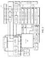
- FIG. 2is an abstract functional diagram illustrating example components within the WCD in accordance with some embodiments
- FIG. 3Ais a view of an exterior window of a WCD with example components exposed in accordance with some embodiments
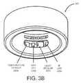
- FIG. 3Bis a view of an interior window of a WCD with example components exposed in accordance with some embodiments
- FIG. 3Cis a view of the exterior windows of an alternative WCD with example components exposed in accordance with some embodiments.
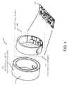
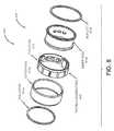
- FIG. 4is an exploded view of a WCD illustrating a battery and a flexible circuit which are configured to fit inside the housing of the WCD in accordance with some embodiments;
- FIG. 5is a perspective view of the flexible circuit of FIG. 4 in accordance with some embodiments.
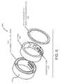
- FIG. 6is an exploded view of a WCD with an alternative charging mechanism in accordance with some embodiments.
- FIG. 7is a perspective view of an alternative design of a WCD in accordance with some embodiments.
- FIG. 8is an exploded view of the WCD of FIG. 7 illustrating another alternative charging mechanism in accordance with some embodiments
- FIG. 9Ais a perspective view of a charging device for the ring station in accordance with some embodiments.
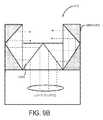
- FIG. 9Bis an abstract diagram illustrating a partial structure of the charging station of FIG. 9A in accordance with some embodiments.
- FIG. 10is an example screenshot illustrating a user interface of a mobile application coupled to the WCD and displaying fitness monitoring readings in accordance with some embodiments;
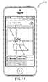
- FIG. 11is an example screenshot illustrating a user interface of a mobile application coupled to the WCD and displaying sensor readings (e.g., for calibration purposes) in accordance with some embodiments;
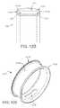
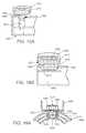
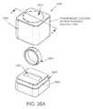
- FIG. 12Ais a perspective view of a wearable computing device (WCD) according to one or more aspects of the disclosure
- FIG. 12Bis a side view of a WCD according to one or more aspects of the disclosure.
- FIG. 12Cis a front view of the WCD according to one or more aspects of the disclosure.
- FIG. 12Dis a cross section of the WCD along the line A-A of FIG. 12C ;
- FIG. 12Eis a perspective view of the internal housing without external potting
- FIG. 12Fis a perspective view of the internal housing with a portion of the external potting removed and showing one or more components and printed circuit board (PCB);
- PCBprinted circuit board
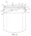
- FIG. 13is a cross section of a WCD according to another aspect of the disclosure.
- FIG. 14Ais a cross section of a WCD according to another aspect of the disclosure.
- FIG. 14Bis a perspective view of the PCB and stiffener element of FIG. 14A ;
- FIG. 14Cis a perspective view of the PCB and stiffener element of FIG. 14A ;
- FIG. 14Dshows a cross section of the WCD at a point in time when the PCB is being inserted into the internal space and prior to the application of potting
- FIG. 14Eis a cross section of the WCD of after a potting material has been applied subsequent to the WCD of FIG. 14D ;
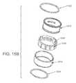
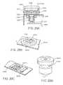
- FIG. 15Adepicts a perspective view of a WCD according to another aspect of the disclosure.
- FIG. 15Bis an exploded view of the WCD of FIG. 15A ;
- FIG. 16Ais an exploded view of a housing and a PCB of a WCD according to one or more aspects of the disclosure
- FIG. 16Bis a cross section of FIG. 16A along line B-B;
- FIG. 16Cis a perspective view of the WCD with potting material
- FIG. 17Adepicts a cross section of a WCD employing charging by concentrated light source according to one or more aspects of the disclosure
- FIG. 17Bdepicts a cross section of a WCD employing charging by concentrated light source according to another aspect of the disclosure
- FIG. 17Cis a perspective view of a base assembly and WCD 700 according to one or more aspects of the disclosure.
- FIG. 17Ddepicts a perspective view of internal components of the base assembly 750 and WCD 700 according to another aspect of the disclosure.
- FIGS. 17E-Fdepict other CPV configurations according to one or more aspects of the disclosure.
- FIG. 17Gis perspective view of a WCD and base assembly with a 1 ⁇ 3 CPV arrangement
- FIG. 18Adepicts a cross section of a WCD 800 employing charging by concentrated light source according to another of the disclosure
- FIG. 18Bdepicts a cross section of a WCD employing charging by concentrated light source according to another of the disclosure
- FIG. 19Adepicts a cross section of a WCD employing charging by concentrated light source according to another of the disclosure.
- FIG. 19Bdepicts a cross section of a WCD employing charging by concentrated light source according to another of the disclosure.
- FIG. 19Cdepicts a schematic diagram of magnets that can be used in a WCD and/or base assembly according to one or more aspects of the disclosure
- FIG. 19Ddepicts a schematic diagram of magnets that can be used in a WCD and/or base assembly according to one or more aspects of the disclosure
- FIG. 19Eis a perspective view of a WCD and a base assembly according to one or more aspects of the disclosure.
- FIG. 20Ais a cross section of a WCD engaged with a base assembly 1050 according to one or more aspects of the disclosure
- FIG. 20Bis a perspective view of a PCB 1040 b with a CPV 1030 b and ferrous element 1020 b configuration according to one or more aspects of the disclosure;
- FIG. 20Cis a perspective view of a PCB with a CPV 1030 c and ferrous element 1020 c configuration according to one or more aspects of the disclosure
- FIG. 20Dis a perspective view of a magnet and a concentrated light source 1070 d according to one or more aspects of the disclosure.
- FIG. 21Ais a schematic view of a WCD showing components used for identifying the wearer of the WCD;
- FIGS. 21B-Care perspective views of a skin surface according to one or more aspects of the disclosure.
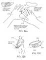
- FIG. 22Ais a perspective view of a user employing ECG monitoring according to one or more aspects of the disclosure.
- FIG. 22Bis a view of a human with an electric pathway though his body according to one or more aspects of the disclosure.
- FIG. 22Cis a perspective view of a WCD that can employ ECG monitoring according to one aspect of the disclosure.
- FIG. 23Ais a perspective view of the hand of a user in various positions employing the navigational features of the WCD;
- FIG. 23Bis a flow chart depicting a method of providing feedback to a user according to one or more aspects of the disclosure.
- FIG. 24Ais a schematic diagram of a system 1400 for controlling an environment of a user according to one or more aspects of the disclosure
- FIG. 24Bis a side view of a WCD showing one or more temperatures sensors according to one or more aspects of the disclosure
- FIG. 24Cis a system diagram of a system for controlling home appliances according to one or more aspects of the disclosure.
- FIG. 24Dis a flow chart depicting a method of controlling home appliances according to one or more aspects of the disclosure.
- FIG. 25is a perspective view of the hand of a user employing a two-factor authentication technique according to one or more aspects of the disclosure.
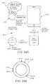
- FIG. 26Ais a schematic view of a charging apparatus for charging the WCD according to one or more aspects of the disclosure.
- FIG. 26Bshows a WCD including an RF antenna and charging circuitry
- FIG. 26Cis a block diagram of the charging apparatus according to one aspect of the disclosure.
- FIG. 26Dis a schematic view of the charging apparatus of FIG. 26A and the WCD of FIG. 26B according to one or more aspects of the disclosure;
- FIG. 27Ais a pictorial diagram and FIG. 27B is a block diagram of a WCD employing flash storage according to one or more aspects of the disclosure;
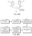
- FIG. 28Ais a schematic diagram of one or more WCDs performing proximity functions according to one or more aspects of the disclosure.
- FIG. 28Bis a schematic diagram of one or more WCDs performing proximity functions according to one or more aspects of the disclosure.
- FIG. 29Ais a flow chart depicting a method of initiating gesture input according to one or more aspects of the disclosure.
- FIG. 29Bis a chart showing acceleration vs. time as measured by the accelerometer of the WCD;
- FIG. 30is a perspective view of a WCD 2000 employing a reset function
- FIG. 31Ais a perspective view of a WCD including an LED indicator according to one or more aspects of the disclosure.
- FIGS. 31B and 31Care cross sections along line C-C of a WCD employing an LED indicator according to one or more aspects of the disclosure
- FIG. 32is flow chart depicting a method of communicating with a near field communication (NFC) device according to one or more aspects of the disclosure
- FIG. 33Adepicts a perspective view of a WCD assembly according to one or more aspects of the disclosure
- FIGS. 33B-Ddepict exploded views of the WCD assembly of FIG. 33A ;
- FIG. 33Edepicts a cross sectional view of the WCD assembly along A-A
- FIGS. 34A-Bdepict a WCD assembly according to one or more aspects of the disclosure
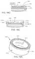
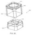
- FIG. 35Adepicts an enclosure or case for storing a WCD according to one or more aspects of the disclosure
- FIG. 35Bis a cross sectional view of the assembled enclosure of FIG. 35A along the line B-B;
- FIG. 35Cdepicts a cross sectional view of the assembled enclosure of FIG. 35B along line A-A;
- FIG. 36depicts an enclosure including air vents according to one or more aspects of the disclosure
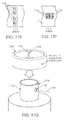
- FIG. 37depicts a method of sizing a finger according to one or more aspects of the disclosure.
- FIG. 38is a pictorial diagram showing a plurality of image perspectives of a user's hand
- FIG. 39depicts a sizing tool for sizing the finger of a user
- FIG. 40depicts a sizing tool for sizing the finger of a user according to an alternate example
- FIG. 41depicts yet another alternate example of a sizing tool for sizing the finger of a user
- FIG. 42depicts a method of monitoring activity according to one or more aspects of the disclosure.
- FIG. 43depicts a method of determining whether a user is wearing gloves according to one or more aspects of the disclosure
- FIG. 44depicts a method of securing data onboard the WCD according to one or more aspects of the disclosure
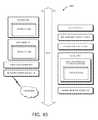
- FIG. 45Ais a timepiece system according to one or more aspects of the disclosure.
- FIG. 45Bis a bottom view of the TCD
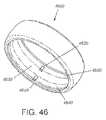
- FIG. 46depicts a WCD with a pair of LED indicators disposed at an inward-facing portion of the WCD;
- FIG. 47Ais a system for generating and managing alerts according to one or more aspects of the disclosure.
- FIG. 47Bdepicts a block process diagram for generating and managing alerts according to one or more aspects of the disclosure
- FIG. 47Cis a flow chart depicting a method for generating and managing alerts according to one or more aspects of the disclosure
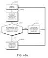
- FIG. 48Ais a method for variable sampling according to one or more aspects of the disclosure
- FIGS. 48B and 48 care graphs depicting one or more aspects of the sample method of FIG. 48A ;
- FIG. 49is a diagrammatic representation of a machine in the example form of a computer system within which a set of instructions, for causing the machine to perform any one or more of the methodologies discussed herein, may be executed.
- the present disclosuredescribes a wearable computing device (WCD) that enables a wearable fitness monitor(s)/computer(s) which is suitable for prolonged usage with accurate results.
- the WCDcan be in the form of a ring that can be worn on the finger of a human (or animal) user.
- the WCD of the present disclosureis depicted as a ring that can be worn on the finger of a user, other shapes, designs, and form factors can be utilized for the WCD.
- the WCDcan be in the form of a wrist band, bracelet, necklace, earring, or any other type of wearable accessory.
- references to the finger of a user in the present applicationcan be considered to apply to other portions of a human body depending on the form of the WCD, such as wrist, neck, ear, etc.
- Coupledmeans connected directly to or connected through one or more intervening components or circuits. Any of the signals provided over various buses described herein may be time-multiplexed with other signals and provided over one or more common buses. Additionally, the interconnection between circuit elements or software blocks may be shown as buses or as single signal lines. Each of the buses may alternatively be a single signal line, and each of the single signal lines may alternatively be buses, and a single line or bus might represent any one or more of a myriad of physical or logical mechanisms for communication (e.g., a network) between components.
- the present embodimentsare not to be construed as limited to specific examples described herein but rather to include within their scope all embodiments defined by the appended claims.
- FIG. 1Ais a perspective view 100 of a WCD 110 illustrating an exterior window 120 in accordance with some embodiments
- FIG. 1Bis a perspective view 102 of the WCD 110 of FIG. 1A illustrating an interior window 130 .
- the present embodiments of the WCD 110can function as fitness monitors/computer which is suitable for prolonged usage so as to create accurate results.
- the WCD 110can function as a remote input device through, for example, gesture recognition.
- the WCD 110can further function as a sleep monitor, a heart rate sensor, a cardiac monitor a body temperature detector, or the like. It is noted that, for those embodiments which can function as a cardiac monitor (e.g., that measures electrocardiogram (EKG)), it may be necessary to establish a closed loop (e.g., for the electrical measurement of EKG) across the heart.
- a separate conductive padcan be coupled to the WCD 110 so that a user can pinch the pad with fingers on an opposite hand,
- the WCD 110can be worn by the user (e.g., on a finger) for fitness, physical activity, biological data monitoring as well as for gestural input or other suitable purposes.
- the WCD 110can include the exterior window 120 on its exterior wall for input/output data transmission and reception, battery recharge, or status indication.
- the WCD 110can also include the interior window 130 on its interior wall for various monitoring or sensing activities.
- the form factor of the WCD 110allows it to be worn for prolonged hours with constant and consistent contact with the skin area, thereby creating a more reliable and extended recording (e.g., as compared to aforementioned conventional fitness monitors) of the user's fitness activity, physical exercise, as well as health information such as heart rates and body temperature. More implementation details regarding the WCD 110 are discussed below.
- FIG. 1Cis a perspective view of an alternative WCD design 112 of the WCD 110 of FIG. 1A in accordance with some embodiments.
- the WCD 112includes a second exterior window 124 in addition to a first exterior window 122 .
- the two exterior windows 122 and 124can include spacing between the two windows 122 and 124 so that the mechanical strength of the housing structure of the WCD 112 may be stronger than that of the WCD 110 , which is shown to include one single exterior window 120 .
- radio antennase.g., Bluetooth
- other sensitive circuitrycan be positioned in the second exterior window 124 away from the first exterior window 122 so that quality of reception may be improved.
- FIG. 2is an abstract functional diagram 200 illustrating example components within the WCD (e.g., WCD 110 ) in accordance with some embodiments.
- the WCD 110can include a processor module 210 , a plurality of sensor modules 220 , a status indicator module 230 , a power generation and management module 240 , a communication module 250 , a memory 260 , and miscellaneous modules 270 (e.g., a real-time clock (RTC) crystal oscillator as illustrated in FIG. 2 ).
- the WCD 110can also include a battery module 280 that provides electrical power for the WCD 110 .
- the battery 280can be of a lithium-polymer type or a zinc-polymer type.
- modules illustrated in diagram 200are for purposes of facilitating a better understanding of the present embodiments; other suitable modules may be included in the WCD 110 and are not shown for simplicity.
- the term “components”is considered to generally include any of the modules depicted and/or described in FIG. 2 , as well as any other modules described herein.
- a portion of the communication module 250e.g., the Bluetooth Chip as shown in FIG. 2
- the processor module 210can be combined into the processor module 210 .
- one or more modules hereincan be combined into one to form a system-on-the-chip (SOC).
- SOCsystem-on-the-chip
- the processor module 210can have generic characteristics similar to general purpose processors or may be application specific integrated circuitry that provides arithmetic and control functions to the WCD 110 .
- the processorcan be any type of processor, such as a processor manufactured by AMtel, Freescale, Nordic Semiconductor, Intel®, AMD®, or an ARM® type processor.
- the processor module 210can include a dedicated cache memory (not shown for simplicity).
- the processor module 210is coupled to all modules 220 - 270 in the WCD 110 , either directly or indirectly, for data and control signal transmission.
- the memory 260may include any suitable type of storage device including, for example, ROM, such as Mask ROM, PROM, EPROM, EEPROM; NVRAM, such as Flash memory; Early stage NVRAM, such as nvSRAM, FeRAM, MRAM, or PRAM, or any other type, such as, CBRAM, SONOS, RRAM, Racetrack memory, NRAM, Millipede memory, or FJG. Other types of data memory can be employed as such are available in the form factor desired.
- ROMsuch as Mask ROM, PROM, EPROM, EEPROM
- NVRAMsuch as Flash memory
- Early stage NVRAMsuch as nvSRAM, FeRAM, MRAM, or PRAM, or any other type, such as, CBRAM, SONOS, RRAM, Racetrack memory, NRAM, Millipede memory, or FJG.
- Other types of data memorycan be employed as such are available in the form factor desired.
- the memory 260can also store data generated from the processor module 210 . It is noted that the memory 260 can be an abstract representation of a generic storage environment. According to some embodiments, the memory 260 may be comprised of one or more actual memory chips or modules. In some embodiments, the memory 260 can function as a temporary storage (e.g., for firmware updates, and/or for avoiding accidental malfunctions (such as so-called “bricking”)).
- the sensor modules 220can include various sub-modules for the WCD 110 to perform different monitoring or sensing activities.
- a view 302 of the interior window (e.g., window 130 ) of a WCD (e.g., WCD 110 ) with example components exposedis shown in FIG. 3B .
- the sensor modules 220can include a temperature sensor 320 a , a red light emitting diode (LED) 320 b , a light sensor 320 c , and an infra-red LED 320 d .
- LEDred light emitting diode
- the sensors in the sensor modules 220can be configured and positioned in a way that is close to the skin (e.g., facing the interior window 130 of the WCD 110 ).
- the sensor modules 220can further include sensors that are not directly related to biological sign monitoring; some examples of these sensors include accelerometers, gyroscopes, vibration, sensors (e.g., a magnetometer or a digital compass), or other suitable sensors (e.g., for gesture recognition).
- the magnetometercan measure the strength and/or direction of a prevailing magnetic field.
- the magnetometercan be used during global positioning and/or navigation.
- the magnetometercan be used to measure a directional heading when the WCD is in motion and can supplement position data where the WCD is out of communication range.
- the accelerometers in the sensor modules 220can detect movements in multiple (e.g., 3 ) dimensions or axes.
- the accelerometercan measure force of acceleration of the WCD and can measure gestures performed by a user while wearing the WCD.
- the accelerometercan detect acceleration of the user while wearing the WCD. This can permit tracking of activity level, such as steps taken or number of laps swum in a pool.
- the temperature sensorcan be any type of sensor that detects temperature, such as a thermistor, PTC, NTC, etc.
- the temperature sensorcan use IR light emitted from an object to calculate a surface temperature of the object in a manner clear to those of ordinary skill in the art.
- the processor module 210 and the sensor modules 220can enable the WCD 110 to perform multiple functions including, for example, pedometer, sleep monitor (e.g., which monitors sleep quality), heart rate sensor, pulse oximetry, skin (and in select embodiments, ambient) temperature.
- sleep monitore.g., which monitors sleep quality
- heart rate sensore.g., which monitors heart quality
- pulse oximetrye.g., skin temperature
- skinand in select embodiments, ambient temperature
- some embodiments of the WCD 110can further function as a gesture input device.
- the WCD 110can detect finger motions or gestures which may be difficult for conventional fitness sensors to detect, such as a tap, a snap, a knock on the table, and the like.
- the WCD 110can utilize the accelerometer to measure the activity level (e.g., arm movement) in conjunction with the measured heart rate to determine if the user is walking horizontally, running, swimming, or climbing stairs. Other activities can be identified by the WCD 110 may include biking or sleeping.
- the activity levele.g., arm movement
- Other activitiescan be identified by the WCD 110 may include biking or sleeping.
- the WCD 110can also be programmed to learn particular gestures or physical exercise from the user using, for example, a training mode.
- the usercan instruct (e.g., using a computer or a mobile device of the user) the WCD 110 to enter the training mode and perform the gesture or physical exercise; the WCD 110 can record the readings from the sensor modules 220 , recognize patterns therefrom, and store the result in, for example the memory 260 , so that such gesture or exercise can be recognized by the WCD 110 after the training.
- the WCD 110can be configured (e.g., via a mobile application running on a mobile device of the user) so that the recognized gestures can perform functions designated by the user, such as clicks, swipes, unlocks, or media player controls.
- the WCD 110can include near field communication (NFC) chips so that certain functions (e.g., unlocking a smart phone) can be performed when the WCD 110 touches upon or otherwise be detected by another NFC device.
- NFCnear field communication
- the unlocking function of the WCD 110can also unlock a user device (e.g., a phone) via the communication module 250 (e.g., Bluetooth) by the WCD 110 transmitting a proper unlock code.
- the WCD 110can function as a key or a control device for keyless access to home, automobile, or other suitable user authentication processes.
- the WCD 110can also be integrated with games and game consoles so that it can function as an input device to those games and consoles.
- the WCD 110can be adapted for use in medical and home health monitoring, or as a transportation safety device (e.g., that broadcasts emergency messages to relevant authorities).
- sensors/functionalities of the WCD 110can include an inertial measurement unit (IMU) (e.g., for more complex gesture recognition, a near-infrared (NIR) spectrometer (e.g., for measuring light absorption and deriving blood glucose/blood alcohol/CO2 content), a Galvanic skin response sensor (e.g., for measuring sweat/nervousness), an electrocardiogram (ECG or EKG), and so forth.
- IMUinertial measurement unit
- NIRnear-infrared
- Galvanic skin response sensore.g., for measuring sweat/nervousness
- EKGelectrocardiogram
- the processor module 210can determine (e.g., based on identified physical activities, routine pattern, and/or time) a frequency at which one or more sensors in the sensor modules 220 should operate. Because it is recognized in the present disclosure that the heart rate of a human being typically does not vary too widely (e.g., beyond a certain percentage of what has been previously measured), in some embodiments, the WCD 110 can automatically adjust the sensor modules 220 (e.g., to slow down) so as to save power. More specifically, some embodiments of the WCD 110 can include a phase-locked loop or logic to predict the pulse width by determining lower and upper ranges in which the heart rate is predicted to be, thus only powering up the sensor modules 220 at the time of the predicted heartbeats.
- the WCD 110determines that the user is at sleep (e.g., based on the heart rate, the body temperature, together with the movements detected by the accelerometer and/or the vibration detector), the WCD 110 can slow down its heart rate detection frequency (e.g., from 1 measurement per second to 1 measurement per 10 seconds) and skip the measurement of several heartbeats because it is unlikely that the heart rate will change drastically during that period. Conversely, if the WCD 110 determines that the user is performing a high intensity physical exercise, the WCD 110 can increase the frequency of monitoring and recording of the sensor modules 220 .
- the WCD 110also includes various modules coupled to the processor module 210 for, by way of example but not limitation, input/output data transmission, battery recharge, or status indication.
- a view 300 of the exterior window (e.g., window 120 ) of a WCD (e.g., WCD 110 ) with example components exposedis shown in FIG. 3A .
- the modules configured to face the exterior window 120 of the WCD 110can include parts from the status indicator module 230 , the power generation and management module 240 , and the communication module 250 .
- the WCD 110includes the status indicator module 230 coupled to the processor module 210 to indicate various statuses.
- the status indicator module 230includes a light emitting diode (LED) 330 , such as shown in FIG. 3A .
- the LED 330can be a single red/green/blue (RGB) LED.
- the status indicator module 230can include other suitable types of indicator devices including, for example, a single color LED, an electrophoretic ink (or “e-ink”) display, a persistent display, or the like.
- the WCD 110can utilize the indicator module 230 (e.g., via the RGB LED 330 through the exterior window 130 ) to visually communicate with the user.
- a red colorcan be displayed (e.g., for a predetermined period of time) by the LED 330 that the WCD 110 needs to be recharged, and a green color can be displayed to indicate that the WCD 110 is fully charged.
- a blue colorcan be displayed when the communication module 250 is in use.
- the usercan program a fitness goal (e.g., a target heart rate) to the WCD 110 so that, for example, a green color can be displayed when the heart rate is below the target, a yellow color can be displayed when the target is reached, and a red color can be displayed when the heart rate is above a certain percentage of the set target.
- Some embodiments of the WCD 110include the communication module 250 for wireless data transmission.
- the communication module 250includes one Bluetooth chip and a Bluetooth antenna 350 , such as shown in FIG. 3A .
- One or more embodiments of the WCD 110also provides the capability of storing activity logs (e.g., in the memory 260 ). More specifically, fitness activities, exercise histories, as well as recorded biological signs such as heart rate and body temperature, can be stored onboard in the memory 260 of the WCD 110 . Each data entry in the activity logs can be time-stamped using, for example, an onboard real-time clock (e.g., which may be included in miscellaneous modules 270 ). For power saving and other purposes, the activity log can be downloaded (e.g., via the communication module 250 ) when requested by the user.
- the activity logcan be pushed (e.g., via email or other suitable means) by the WCD 110 to a user device at a time designated by the user.
- the memory 260can store up to a full week worth of activity logs.
- the WCD 110can include the power generation and management module 240 for recharging the battery 280 and for providing electrical power to various modules 210 - 270 in the WCD 110 .
- the power generation and management module 240includes one or more concentrated photovoltaic (CPV) cells 340 , such as shown in FIG. 3A .
- the CPV cells 340can be high-efficiency tandem solar cells and can be attached on the flexible printed circuit (e.g., circuit 415 , 515 ). Because the small form factor of the embodiments of the WCD 110 , CPV cells 340 , which can absorb more light energy from a wider spectrum of light than the traditional solar cells, are used. In some embodiments, multiple (e.g., 3 ) CPV cells 340 can be configured in series to provide sufficient voltage and/or current for charging the battery 280 .
- the WCDcan include one or more sensing or imaging devices that can be any type of device capable of detecting electromagnetic radiation, such as visible light, IR, NIR, UV, etc.
- the deviceis an imaging device, such as a CMOS or CCD camera.
- the WCD 110can be placed or docked into a charging station for recharging.
- a perspective view 900 of an example charging station 910 for the WCD 110is shown in FIG. 9A .
- the charging station 910can have concentrated light source circumferentially around the WCD 110 so that the user does not have to be concerned with whether the WCD 110 is facing the right direction for charging.
- Some embodiments of the charging station 910can include a light distribution means that takes a single light source and distributes the light all around.
- An abstract diagram illustrating a partial structure of the light distribution means inside the charging device of FIG. 9Ais shown in FIG. 9B .
- regular outdoor sunlight or other ambient light sourcecan still function as a secondary source of energy so that the CPV cells 340 on the WCD 110 can extend the operational time provided by the battery 280 .
- energy source attached to the power generation and management module 240can be passive; for example, some embodiments provides that a clip with a concentrator lens can be attached to the WCD 110 in a way such that the power generation and management module 240 can charge the battery 280 using natural sunlight.
- gemstone(s)e.g., sapphire, diamond, or other suitable materials
- in the shape of a dome or with faceted protrusioncan be configured to concentrate/magnify light energy while also serving as a decorative feature.
- the power generation and management module 240can include electromagnetic induction charging coil so that a WCD (e.g., ring 610 ) can be charged using an inductive charger.
- FIG. 6shows an exploded view 600 of such alternative embodiment of WCD with the inductive charging mechanism including the charging coil 640 , as well as battery 680 , housing 612 , and rigid-flex PCBA 615 .
- the inductive charging coil 640there may be a need to manufacture the inductive charging coil 640 in different sizes that correspond to different ring sizes.
- the efficiency of the electromagnetic induction charging mechanismmay be adversely affected by the adoption of a metallic housing.
- the coilcan be placed on the inner or outer sides of the ring by positioning the coil beneath a window in the metal housing of the ring.
- one or more of the componentscan be selected to minimize power usage.
- a processor, memory, or any other componentcan be selected based on rated power usage.
- the power generation and management module 240can include thermoelectric generator (TEG) modules so that a WCD (e.g., WCD 710 , 810 ) can be charged by the difference between the body temperature and the ambient temperature.
- TOGthermoelectric generator
- FIG. 7is a perspective view 700 of such alternative design
- FIG. 8is an exploded view 800 of the WCD 710 of FIG. 7 .
- FIGS. 7 and 8is an alternative design of the housing for the WCD where the ring includes an outer ring 812 a , an inner ring 812 b , and insulators 814 a and 814 b .
- TEGsfor charging the battery may be less than ideal since the difference between body temperature and ambient temperature might not be great enough to fully charge the battery, and that in many occasions (e.g., during sleep), the temperature difference needed for TEG to generate electricity may quickly disappear (e.g., since the WCD 710 , 810 may be covered inside the comforter).
- the batterycan be any type of battery, such as a rechargeable battery.
- the batterycan be a thin, flexible lithium ceramic chemistry battery.
- the batterycan be a circular formed lithium polymer or lithium ion battery.
- the batterycan provide power to any of the components described above.
- the batterycan be a lithium cell integrated directly with the flexible PCB described above.
- Other implementationscan integrated the battery directly onto the housing to reduce the volume of space taken up by battery packaging.
- the WCDcan also include one or more polymer or piezo actuators for providing appropriate haptic or physical feedback and alerts to a user while the user is wearing the ring.
- the piezo actuatorcan also provide audible feedback to a user.
- the WCD 110can be used with a software application (e.g., a mobile phone application for the Apple iOS or the Google Android OS) which can run on the user's computing device (e.g., a mobile device such as a smart phone).
- the software applicationcan facilitate the mobile device of the user to couple to the WCD 110 (e.g., via the communication module 250 ) for data communication, such as downloading activity logs, changing configuration and preferences, training the WCD.
- the software applicationcan also generate a user interface showing the results or readings from the health and fitness tracking performed by the WCD 110 .
- FIG. 10is an example screenshot illustrating such user interface 1000 displaying fitness monitoring readings in accordance with some embodiments.
- the WCD 110can be used for gesture input, and the software application can facilitate the user to customize gesture input and control.
- FIG. 11is an example screenshot illustrating such user interface 1100 displaying sensor readings (e.g., for calibration purposes) in accordance with some embodiments.
- the WCD 110can also be used directly with other Bluetooth enabled devices such as electronic locks or keyless car entry.
- the WCD 110can also control other devices via a smartphone and other Wireless LAN enabled devices such as home automation systems.
- FIG. 3Cis a view 304 of two exterior windows of an alternative WCD (e.g., WCD 112 of FIG. 3C ) with example components exposed in accordance with some embodiments.
- the components 330 , 340 , and 350 shown in FIG. 3Cfunction similarly to those components described in FIG. 3A .
- some componentse.g., antenna 350
- FIG. 4is an exploded view 400 showing an exemplary WCD 410 (e.g., WCD 110 ) illustrating a battery 480 and a flexible circuit 415 which are configured to fit inside a housing 412 of the WCD 410 .
- WCD 410e.g., WCD 110
- a human being's fingercan come in various different sizes and so should the WCD 410 .
- the modules 210 - 270are formed on a flexible or rigid-flex printed circuit (FPC) board, an example 500 of which is shown as FPC 515 in FIG. 5 .
- FPCflexible or rigid-flex printed circuit
- one or more embodimentsprovide that the FPC 515 and the battery 480 are not specific to a ring size, and that the same circuitry and/or battery can fit a multitude of sizes.
- the WCD 410provides a desirable form factor for a user to wear it for a prolonged period of time.
- the edges and the shape of the WCD 410can be configured in a way that is comfortable and ergonomic; for example, the finished parts of the embodiments are to be free from burrs and sharp edges.
- the material which forms the housing portion of the WCD 410can include medical grade metallic alloys that reduce the likelihood of allergic reactions. Examples of the housing material include stainless steel, tungsten carbide, titanium alloy, silver, platinum or gold.
- the U-shape of the ring housing 412allows for the flexible PCB 415 to be inserted into the edge of the WCD 410 .
- the windowse.g., windows 120 , 130
- the windowscan align with the operating circuitry to allow, for example, battery charging, Bluetooth connection, and user feedback LED/micro display on the outer wall, and biological feedback sensors (e.g., pulse oximetry, temperature sensor) on the inner wall.
- the WCD 410can be completely sealed using potting epoxy.
- the sealing epoxycan be transparent to allow light to pass through for the CPVs and sensors.
- the WCD 410can be potted with two different compounds.
- the body of the WCD 410can be filled with clear material, and the edge of the WCD 410 can be filled with an opaque material so that different colors can be incorporated (e.g., as a decorative element). It is noted that sealing the assembly using potting epoxy can also bring the additional benefit of making the WCD 410 completely or almost completely waterproof as well as increasing the structural rigidity of the WCD 410 .
- FIG. 12Ais a perspective view and FIG. 12B is a side view of a WCD 1200 according to one or more aspects of the disclosure.
- the WCD 1200can be in the shape of a ring and can be worn on any of the five fingers (including the thumb) of (typically) a human user.
- the WCD 1200can define an interior diameter d 1 and exterior diameter d 2 .
- the interior diameter d 1can be defined as the distance between opposing points on the interior surface of the ring, with the interior surface being the portion of the WCD facing the finger of a user while the device is worn by the user.
- the interior surface of the WCDcan generally define a finger space for receiving the finger of the user.
- the exterior diameter d 2can be defined as the diameter between opposing points on the exterior surface of the ring, with the exterior surface being the portion of the WCD opposed to the interior surface and facing away from the finger of the user.
- the interior diameter d 1 and exterior diameter d 2can be any size to accommodate any finger size.
- d 2is determined by d 1 plus a thickness of any components and/or flexible circuit boards disposed within the WCD.
- the finger space of the WCD 1200can be any shape, such as ovular, elliptical, or the like, to accommodate users with atypical finger profiles.
- the dimensions of the interior and/or exterior diametermay be measured according to other variables, such as length, width, major diameter, minor diameter, etc.
- the WCD interior diameter d 1(the diameter generally defining the ring size) can be in an approximate range of 12 mm to 24 mm so as to accommodate finger sizes ranging from a small child to a larger adult, and on any acceptable finger, including the thumb.
- the exterior diameter d 2can also be any reasonable size or shape, and can define an approximate range of between 18 mm and 30 mm.
- the thickness between diameters d 1 and d 2can vary widely, but can typically reside in an approximate range of 1.5 mm to 3 mm.
- the width WR of the WCD along the direction of finger extension (finger longitudinal direction)is widely variable, and can be selected, in part to accommodate internal and external components. In a non-limiting example, the width WR is in a range of approximately 3 mm to 8 mm.
- the WCD 1200can include an overall housing 1210 that includes an internal housing 1212 and an external potting or encapsulant 1214 . Together, the internal housing 1212 and external potting 1214 combine to form the overall form factor of the WCD 1200 , in addition to providing a housing for one or more electronic components stored within the housing 1210 of the WCD 1200 , as will be described in greater detail below.
- the internal housing 1212can be formed of any material, such as a nonconductive material, a conductive material, a ferrous material and/or a nonferrous metal, composite material (e.g. carbon-fiber and/or glass fiber composite) a dielectric material, or a combination of any of the above.
- the material of the inner housing 1212is conductive and nonferrous, such as aluminum, titanium, or stainless steel.
- the internal housingcan be formed of a polymer, such as plastic.
- the external potting 1214can be formed of any material, solid or gelatinous, that can provide resistance to shock and/or vibration and can prevent moisture and/or debris from entering the housing 1210 of the WCD 1200 , such as silicone, epoxy, polyester resin or any other polymer.
- the external potting 1214can be transparent.
- the transparent external pottingcan allow electromagnetic radiation, such as visible, IR, or UV light sources from inside the housing 1210 to pass through the external potting 1214 without the need of a window or discontinuity in the external potting 1214 and without changing the optical properties of the radiation.
- electromagnetic radiation sources, such as visible, IR, or UV light, external to the housingcan pass through the external potting 1214 and can be detected by, sensed by, or fall incident upon internal components of the WCD 1200 without the need for a window or discontinuity in the housing and without changing the optical properties of the radiation.
- the external potting 1214can be tinted.
- the tintcan be cosmetic and can prevent the internal components of the WCD to be visible by the user.
- optical properties of light passing therethoughmay be slightly changed. For example, certain colors of the light can be filtered and can result in decreased power transmission.
- external potting 1214can be applied to any of the pottings described below.
- the internal housing 1212can define a window 1216 .
- the internal housingis formed of a material that completely or partially prevents light (or other electromagnetic radiation) from passing through the internal housing 1212 .
- the internal housing 1212can define the window 1216 to allow for such radiation to pass through the housing 1212 .
- the window 1216can be generally elliptical-shaped, but can be any other suitable shape according to other examples, such as rectangular, circular, ovular, etc. Since the window 116 is defined by the internal housing 1212 , the window 1216 can face the finger of the user while the user is wearing the WCD 1200 , which can provide many advantageous features and implementations, as will be described in greater detail below.
- FIG. 12Cis a front view of the WCD and FIG. 12D is a cross section of the WCD 1200 along the line A-A of FIG. 12C .
- the internal housing 1212can have a generally U-shaped internal surface 1212 a to accommodate one or more internal components and can define a pair of flanges 1212 b and 1212 c .
- the external potting 1214can extend between the flanges 1212 b and 1212 c of the internal housing to provide an internal space 1220 to accommodate one or more components.
- the internal space 1220 defined by the internal surface 1212 a and the external potting 1214can be hermetically sealed, thereby preventing debris, dust, moisture, or any other unwanted fluids or materials from interacting with the internal components of the WCD 1200 .
- the internal componentscan reside within the internal space 1220 , and the external potting 1214 can be disposed immediately atop the components to provide the seal.
- FIG. 12Eis a perspective view of the internal housing 1212 without external potting 1214 . As shown, the internal surface 1212 a defines a generally U-shaped surface for receiving the components.
- FIG. 12Fis a perspective view of the internal housing 1212 with a portion of the external potting 1214 removed and showing one or more components 1230 and printed circuit board (PCB) 1240 .
- the components and PCBcan be constructed as flex circuits, thereby allowing the components 1230 and PCB 1240 to be geometrically configured within the ring shaped internal space 1220 .
- the PCB 1240can be any type of flexible material clear to those of skill, such as polyimide, PEEK, etc. Additionally, the PCB could be rigid-flex whereby panels of RF 4 are connected together with a flexible substrate.
- the PCB 1240 and the components 1230can be disposed within the internal space 1220 generally defined by the internal surface 1220 a and the flanges 1220 b - c .
- the PCB 1240can define one or more folding regions 1242 that allow the PCB 1240 to conform to the circumference and/or perimeter of the internal surface 1212 a .
- the PCB 1240can extend around at least a portion, or up to an entire circumference, of the internal surface 1212 a .
- the size of the internal diameter d 1 of the WCDcan determine the portion of the internal surface 1212 a around which the PCB 1240 extends.
- the PCB 1240can extend only a portion (an arc) of the overall circumference, while for smaller ring sizes a greater portion (arc) of the circumference can be employed to accommodate PCB 1240 and the internal components 1230 .
- the adjacent portions of PCBcan form an arc angle therebetween by virtue of the folding regions disposed therebetween, allowing for the PCB to be conform to the internal surface 1212 a.
- FIG. 13is a cross section of a WCD 1300 according to another aspect of the disclosure and illustrative embodiments.
- the WCD 1300includes a housing 1310 that includes an external housing 1312 and an internal potting or encapsulant 1314 .
- the external housing 1312includes an internal surface 1312 a that has a generally C-shaped cross section—but alternate cross section shapes, such shapes with an external notch or groove.
- the external housingincludes flanges 1312 b - c that extend toward each other, beyond portions of the internal surface 1312 a , to define a partially enclosed internal space 1320 .
- the WCD 1300can include a battery 1330 , a PCB 1340 , and components 1350 , which can be at least partially or completely disposed within the partially enclosed internal space 1320 .
- the internal potting 1314can extend between the flanges 1312 b - c and can seal the partially enclosed internal space 1320 .
- the componentscan be encapsulated by the internal potting 1314 .
- the PCB 1340 and components 1350can extend along an inner circumference of the internal surface 1312 a
- the external housing 1312can be formed of the same materials as the internal housing 1212 described above, and the internal potting 1314 can be formed of the same materials as the external potting 1214 described above. As also described above, the internal potting 1314 can be transparent and the external housing 1312 can define one or more windows according to one or more aspects of the disclosure.
- FIG. 14Ais a cross section of a WCD according to another aspect of the disclosure and illustrative embodiment.
- the WCD 1400includes a housing 1410 , internal surface 1412 a , an internal or external housing 1412 , an internal or external potting 1414 , an internal space 1420 , a battery 1430 , a flexible circuit 1440 , and one or more components 1450 .
- This exampleis similar to the examples described above with respect to FIGS. 12 and 13 , except the addition of a stiffener element 1442 and the flanges 1412 b - c extend further into the space 1420 toward one another such that the flanges 1412 b - c overlap with the stiffener element 1442 .
- FIG. 14Bis a perspective view of the PCB and stiffener element of FIG. 14A .
- the stiffener element 1442extends beyond an overall width w of the PCB 1440 and extends wider than a distance between flanges 1412 b - c .
- the stiffener elementis disposed between folding regions 1444 .
- the PCB 1440can include one or more stiffener elements 1442 attached thereto, and the elements 1442 can be disposed periodically (in separated intervals) along a length/of the PCB 1440 . As shown in FIG.
- the stiffener element 1442can be disposed underneath the flexible circuit 1440 , e.g., on a face of the flexible circuit 1440 opposed to the face on which the components 1450 are disposed, and can be permanently or semi-permanently attached thereto.
- the stiffener elementcan be implemented in any of the configurations described, and in particular, with either the internal housing/external potting arrangement or the external housing/internal potting arrangement.
- the stiffener element 1442can be formed of any material, such as polyamide or thin FR4, depending on construction of the PCB 1440 .
- the material of the stiffenercan be chosen to be more or less flexible than the PCB 1440 .
- the stiffener element 1442can be a polyamide stiffener disposed on a back surface of a flexible PCB.
- the stiffener element 1442can be FR4 and can be substantially flush with respect to the flanges 1412 b - c .
- the stiffener elementcan extend substantially the distance between flanges 1412 b - c and may not deform upon insertion into the space 1420 .
- the stiffener elementcan include surface features disposed on an edge thereof, with the edge facing one of the flanges 1412 b - c .
- the surface featurescan include a sawtooth profile (e.g., intersecting straight lines at acute angles), or any other type of feature capable of providing an interference fit between flanges 1412 b - c.
- FIG. 14Dshows a cross section of the WCD at a point in time during assembly/manufacture when the PCB 1440 is being inserted into the internal space 1420 and prior to the application of potting 1414 .
- the stiffener 1442contacts the flanges 1412 b - c of the housing 1410 by virtue of the width w of the stiffener element 1442 .
- the stiffener elementhas a predetermined flexibility that allows for a certain amount of flexion, as shown in FIG. 14D .
- the flexionallows for the flexible circuit 1440 to be inserted within the internal space 1420 and can prevent the flexible circuit 1440 from being removed or from accidentally falling out once inserted.
- the flexible circuit 1440is held in place within the space 1420 by virtue of the width of the stiffener element 1442 and the distance between the flanges 1412 b - c .
- the potting 1414can be applied free of the concern of improper positioning of the flexible circuit 1440 .
- FIG. 14Eis a cross section of the WCD of after a potting material 1414 has been applied subsequent to the WCD of FIG. 14D .
- FIG. 15Adepicts a perspective view of a WCD 1500 according to another aspect of the disclosure.
- the WCDincludes a housing 1510 that includes an internal housing 1512 and an external housing 1514 .
- the internal housing 1512can be similar to the internal housing described above with respect to internal housing 1212
- the external housingcan be similar to the external housing described above with respect to external housing 1312 .
- the internal housing 1512can include one or more windows 1516 that can allow electromagnetic radiation (e.g. visible and near-visible light) to pass therethrough, allowing it to fall incident upon components disposed within the housing 1510 and allowing EM radiation sources (e.g. visible light, RF, IR, etc.) within the housing to exit the housing.
- electromagnetic radiatione.g. visible and near-visible light
- EM radiation sourcese.g. visible light, RF, IR, etc.
- FIG. 15Bis an exploded view of the WCD 1500 .
- the WCDcan include internal housing and external housing 1512 and 1514 .
- the WCDcan further include a PCB 1540 and components 1550 .
- potting layers 1502 and 1504can be applied to seal the WCD at both sides thereof to ensure a secure seal.
- FIG. 16Ais an exploded view of a housing 1610 and a PCB of a WCD according to one or more aspects of the disclosure.
- the WCD 1600comprises a housing 1610 with an integral inner wall and outer wall 1612 and 1614 .
- the housingcan be made of any material, such as any material described above with respect to the internal/external housing structures.
- the inner and outer walls 1612 , 1614each define a window in the shape cutaway portions 1616 .
- the cutaway portionsare bounded on three sides by the walls 1612 and 1614 and unbounded at the other side thereof.
- the cutaway portions 1616can be aligned with one another to ensure transmission of radiation into/out of the housing 1610 .
- the space 1620 between the inner and outer walls 1612 , 1614can receive a PCB 1640 , battery, components, etc.
- FIG. 16Bis a cross section of FIG. 16A along line B-B. As shown, the inner and outer walls 1612 , 1614 are directly connected by a floor 1618 . The space 1620 is defined by the space between the inner and outer walls 1612 , 1614 and the floor 1618 .
- FIG. 16Cis a perspective view of the WCD with potting material 1630 .
- the PCB, battery, and componentscan be disposed within the space.
- a potting 1630can be provided atop the components and within the cutaway portion 1616 .
- the potting 1630can be transparent to allow for transmission of light through the cutaway portions 1616 .
- the WCDcan be charged by an external concentrated light source, e.g., laser light, laser diode, etc.
- the photovoltaic device described abovecan include a concentrated photovoltaic element (CPV) that is constructed and arranged to receive concentrated light from the concentrated light source, e.g., laser light from a laser diode, light from a light emitting diode (LED), etc., and converting the received concentrated light into an electric current.
- the photovoltaic devicecan also generate power from nonconcentrated light sources, such as office lighting and ambient sunlight.
- the electric currentcan be used to charge one or more batteries stored within the housing of the WCD.
- FIG. 17Adepicts a cross section of a WCD employing charging by concentrated light source according to one or more aspects of the disclosure.
- the WCD 1700can include a housing material 1710 .
- the WCDcan include a PCB 1720 and a concentrated photovoltaic cell 1730 .
- the WCDcan be positioned adjacent a base assembly or base station 1750 .
- the base assembly 1750can be connected to an external power source 1765 and can have internal circuitry 1760 to power one or more concentrated light sources 1770 , e.g., one or more laser diodes and/or one or more LEDs, disposed within the base assembly 1750 .
- the concentrated light source 1770comprises one or more laser diodes.
- the base assembly 1750can define a first opening 1752 at one portion thereof to allow the concentrated light 1780 to exit the housing of the base assembly 1750 .
- the concentrated light 1780is generated by the concentrated light source 1770 and exits the housing of the base assembly 1750 via a first opening 1752 .
- the concentrated light 1780then enters into the WCD by a second opening 1712 in the housing of the WCD 1700 where it can fall upon the CPV 1730 .
- the CPV 1730can convert the incident concentrated light into a current that can be used to directly power one or more components within the WCD and/or can be used to charge one or more rechargeable batteries onboard the WCD.
- the concentrated light source 1770can be any type of light source that is arranged to generate concentrated light, such as an LED or a laser diode.
- the concentrated lightcan be any type of concentrated and/or coherent electromagnetic radiation, such as laser light and/or LED light.
- the concentrated lightcan have any desired intensity or wavelength, according to the characteristics of the CPV 1730 .
- the source 1770can be a 200 mW laser diode that produces red or green laser light. This can generate approximately 80 mW (or typically less) of power in the WCD where the CPV 1730 includes a plurality of groups of photovoltaics configured in series or in parallel with one another. Each group of photovoltaics can include one or more CPV cells. In another example, the CPV can include a single group of photovoltaics.
- the base assembly 1750 described abovecan include additional components that can interact with the WCD 1700 .
- the base assemblycan include one or more antennas that can communicate according to one or more wireless protocols, such as 3G, 4G, WiFi, Bluetooth®, NFC, or the like, for direct or indirect wired or wireless communication with the WCD or mobile device.
- the base assemblycan employ inductive charging techniques.
- FIG. 17Bdepicts a cross section of a WCD employing charging by concentrated light source according to another aspect of the disclosure.
- the concentrated light source 1770comprises an LED.
- the base assemblycomprises an optical element 1790 positioned adjacent to the concentrated light source 1770 for focusing the LED light onto the CPV inside the WCD.
- the optical element 1790can be any type of optical element, such as a lens.
- the lenscan be formed of any material, such as glass, plastic, etc., and can be any type of lens, such as concave, convex, plano-concave, plano-convex, etc.
- the optical element 1790includes a plano-concave, with the concave portion facing the concentrated light source 1770 .
- the LEDemits light in many directions.
- the optical element 1790can focus the emitted LED light to focus as much of the LED light as possible onto the CPV of the WCD.
- the optical element 1790can be disposed at least partially or completely within the first opening 1752 . In some implementations, the optical element may not be necessary due to LEDs with substantially focused light.
- FIG. 17Cis a perspective view of a base assembly 1750 and WCD 1700 according to one or more aspects of the disclosure.
- the WCD 1700is in the shape of a ring and the base assembly 1750 includes a post 1754 for receiving the ring.
- the post 1754can be cylindrical and can be sized and shaped according to an internal diameter of the WCD in order for the WCD to be received on an external surface of the post.
- the first opening 1752 of the base assembly 1750is formed on a portion of the post 1754 such that, when the WCD 1700 is stored on the post, the second opening 1712 can be aligned with the first opening 1752 to ensure alignment of the CPV and the concentrated light source.
- the base assemblycan receive/transmit power and/or data via external input/output 1795 , which can be a DC power input, a USB input connection or any other acceptable connection/form factor.
- FIG. 17Ddepicts a perspective view of internal components of the base assembly 1750 and WCD 1700 according to another aspect of the disclosure.
- the respective housings of the base assembly and WCDhave been omitted, thereby showing a plurality of concentrated light sources 1770 , optical elements 1790 , and a plurality of CPVs 1730 disposed on mounting substrates 1775 on a PCB.
- the WCDcan include a plurality of CPVs and the base assembly can include a plurality of sources. This allows for a greater current to be generated during charging and for faster charging times of the WCD.
- the CPVs and concentrated light sourcescan correspondingly be disposed in a line, with a constant or variable pitch between respective elements.
- the optical elementcan include corresponding concavities with the same pitch.
- FIGS. 17E-Fdepicts other CPV configurations according to one or more aspects of the disclosure.
- the CPVs 1730can be arranged in a 1 ⁇ 4 array, while FIG. 17F depicts the CPVs arranged in a 2 ⁇ 2 array.
- the WCDcan include any number of CPVs according to any number of geometric configurations.
- FIG. 17Gis perspective view of a WCD and base assembly with a 1 ⁇ 3 CPV arrangement.
- the WCDcan include a 1 ⁇ 3 array of CPVs and the base assembly can include a corresponding 1 ⁇ 3 array of concentrated light sources.
- a usercan then rotate the WCD on the base assembly in order to align the respective first and second openings, as well as the CPV and concentrated light sources.
- FIG. 18Adepicts a cross section of a WCD 1800 employing charging by concentrated light source 1870 according to another aspect of the disclosure.
- the WCDincludes an internal/external housing portion 1810 and an internal/external potting portion 1820 , as described above.
- the base assembly 1850includes a first opening 1852 , but is free of a second opening on the WCD.
- the concentrated light 1880passes through the transparent potting portion and falls incident upon the CPV cell 1830 .
- the sourcecan be a laser diode.
- FIG. 18Bdepicts a cross section of a WCD employing charging by concentrated light source according to another of the disclosure.
- the concentrated light source 1870includes one or more LEDs and the base includes one or more optical elements 1890 for focusing the concentrated light 1880 .
- the LEDsmay be of different wavelengths to provide power to two or more junctions in the triple junction CPV cell.
- FIG. 19Adepicts a cross section of a WCD 1900 employing charging by concentrated light source 1970 according to another of the disclosure.
- the WCD and/or the base assembly 1950can employ one or more magnetic and/or ferrous materials to ensure alignment between the concentrated light source and the CPV cell. Such alignment can improve charging efficiency of the WCD.
- the base assemblyincludes a first opening 1952 and the WCD includes a second opening 1912 to allow for concentrated light to fall incident upon the CPV 1930 .
- the second openingis formed on an external housing portion of the WCD.
- the base assemblycan charge the WCD from an exterior of the WCD, rather than an internal charging method as identified above.
- the WCDcan include a ferrous or other suitable (e.g. ferromagnetic) material 1920 , such as steel, disposed within the housing 1910 .
- the ferrous materialis disposed in a space defined between an internal housing and an external housing.
- the ferrous materialcan surround the CPV.
- the base assemblycan include corresponding magnets 1960 that can cause an attractive force between the WCD and the base assembly into an optimal configuration for charging.
- the magnetscan be disposed within the base assembly and can surround the concentrated light source.
- the magnets 1960can be formed of a rare earth material, such as neodymium or any other acceptable material that provides a requisite magnetic field strength.
- FIG. 19Bdepicts a cross section of a WCD 1900 b employing charging by concentrated light source 1980 b according to another of the disclosure.
- the CPV 1930 b of the WCD 1900is charged from an interior portion, such as by a base assembly 1950 b with a post 1954 b .
- the WCDcan include a ferrous material 1920 b disposed within the housing 1910 b and the base assembly 1950 b can include a magnet 1960 b.
- FIG. 19Cdepicts a schematic diagram of magnets 1920 c , 1960 c that can be used in a WCD and/or base assembly, including a CPV 1930 d and concentrated light source 1930 d , according to one or more aspects of the disclosure.
- the magnets and/or ferrous/ferromagnetic materialscan be axially polarized, with each having a respective north pole and south pole.
- the WCDcan have axially polarized magnets 1920 c with a south pole S facing toward the base assembly
- the base assemblycan have axially polarized magnets 1960 c with a north pole N facing toward the WCD.
- the attractive force between the north and south polescan ensure alignment of the CPV 1930 c of the WCD and the source 1970 c base.
- FIG. 1919Ddepicts a schematic diagram of magnets that can be used in a WCD and/or base assembly according to one or more aspects of the disclosure.
- the base assemblyincludes axially polarized magnet 1960 d , with a north pole N facing toward the WCD.
- the WCDcan include ferrous steel 1920 d , with an attractive force between the ferrous steel and the north pole of the base assembly magnet.
- FIG. 19Eis a perspective view of a WCD and a base assembly according to one or more aspects of the disclosure.
- the WCD 1900 ecan be received by a post 1954 e of a base assembly 1950 e .
- the respective magnets 1960 e and/or ferrous materials 1920 eare shown in phantom to illustrate their positioning with respect to the WCD and base assembly devices and the CPV 1930 e as well as the concentrated light source 1970 e.
- FIG. 20Ais a cross section of a WCD 2000 engaged with a base assembly 2050 according to one or more aspects of the disclosure.
- the magnets 2060can surround the concentrated light source 2070
- the WCDcan include a ferrous steel 2020 , CPV 2022 , and battery 2024 disposed within an internal/external potting 2014 of the WCD.
- the ferrous steel 2020can be disposed on a face of the PCB 2040 and can be encapsulated by the internal/external potting 2014 .
- the base assemblycan include one or more optical elements 2090 for focusing the concentrated light 2080 .
- FIG. 20Bis a perspective view of a PCB 2040 b with a CPV 2030 b and ferrous element 2020 b configuration according to one or more aspects of the disclosure.
- the ferrous element 2020 bcomprises a steel ring that can surround a CPV 2030 b and can be disposed on the PCB 2040 b.
- FIG. 20Cis a perspective view of a PCB 2040 c with a CPV 2030 c and ferrous element 2020 c configuration according to one or more aspects of the disclosure.
- the ferrous element 2020 ccomprises a plurality of rectangular bars disposed on the PCB. In this way, the ferrous element 2020 c can be coated to be reflowed onto the PCB.
- FIG. 20Dis a perspective view of a magnet 2060 d and a concentrated light source 2070 d according to one or more aspects of the disclosure.
- the magnet 2060 dcan include a ring that can extend around a circumference of the concentrated light source 2070 d .
- the magnetic ringcan be attracted to the ferrous steel ring and/or the rectangular ferrous steel examples set forth in 20 A-C above.
- the WCDcan be adapted to uniquely identify the wearer of the WCD using, for example biometric features unique to the user.
- FIG. 21Ais a schematic view of a WCD 2100 showing components used for identifying the wearer of the WCD.
- the WCD 2100can include one or more infrared illumination sources 2110 and an infrared CMOS imaging device 2120 .
- the finger 2190can extend through the finger space of the WCD and the IR source 2110 can illuminate a portion of the skin of the finger 2190 .
- the IR CMOS imaging device 2120can receive light that has been reflected from the skin surface and produce an image of the skin of the finger 2190 .
- the IR source 2110 and the imaging device 2120are positioned near the interior surface of the WCD, e.g., the surface facing the skin of the finger.
- the IR illuminationcan pass through a window provided on the interior housing or can pass through a transparent potting material.
- the WCD 2100can be rotated about an axis passing through the center of the finger space and along the longitudinal direction of the finger.
- the imager 2120can capture a larger swath of the skin surface than if the WCD 2100 were held stationary with respect to the finger during the imaging process.
- the usercan generate a reference capillary map in order to identify himself/herself as the authorized user of the WCD.
- the usercan rotate the WCD around the finger to capture image data of an analyzed section of skin 2192 and on or more capillaries 2194 of the user currently wearing the WCD.
- the image datacan correspond to an overall analyzed section of the skin 2196 of the wearer.
- the image data of the capillariescan be used to generate a reference capillary map of the wearer, which can be stored in the memory, such as flash memory or EEPROM, of the WCD.
- the WCDcan capture image data of the wearer's skin surface that can be compared to the reference capillary map stored in the memory. In this regard, the user need not rotate the device around the finger. Instead, the WCD can compare a subset of the gathered image data to a corresponding subset of reference capillary map. If there a match, within a predetermine error tolerance, the WCD can uniquely identify the wearer as an authorized user of the WCD and as the unique individual who generated the reference capillary map. Once authorized, the wearer can have access to certain functions, features, data, or other content that is not otherwise available without authorization. In another example, the identification can be a step in a transaction or other type of authorization, such as an electronic payment, bank transaction, etc. If the gathered data does not match the reference capillary map, then the user may be prevented from accessing certain features on the WCD.
- the comparison process between sensed capillaries and some or all of the capillary mapcan be implemented using basic pattern recognition algorithms (processes) instantiated in the electronics of the WCD.
- processescan rely on edge detection and similar techniques that should be clear to those of skill in the art and can be sourced from various commercial vendors of biometric recognition software.
- the illuminationcan include NIR illumination and can project radiation into the skin of the finger.
- the reflected NIR illuminationcan then be analyzed to determine one or more characteristics of the blood, such as blood alcohol levels, blood glucose levels, and blood oxygenation levels.
- the WCDanalyzes the reflected radiation to identify wavelengths that were absorbed from the projected radiation by the blood of the user. Techniques and processed used in conjunction with commercially available venous oximeters (for example) can be employed to undertake certain readings.
- FIG. 22Ais a perspective view of a user employing ECG monitoring according to one or more aspects of the disclosure.
- the usercan wear the WCD 2200 on a first finger 2210 of first hand 2220 , and can touch a second finger 2230 of a second hand 2240 to an exterior surface of the WCD 2200 .
- Thiscan provide an electric pathway 2250 through the body, as shown in FIG. 22B , allowing for the transmission of electrical current between distant portions of the body.
- FIG. 22Cis a perspective view of a WCD that can employ ECG monitoring according to one aspect of the disclosure.
- the WCD 2200includes an internal/external housing 2250 with a conductive pad 2260 .
- the conductive pad 2260can be electrically isolated from the external/internal housing 2250 of the WCD, thereby providing distinct and isolated electrical contacts on the WCD.
- the internal/external housing 2250can be in electrical communication with the first finger 2210 of the first hand, while the conductive pad 2260 can be in electrical communication with the second finger 2230 of the second hand.
- an electrical path 2250is formed through the respective hands 2220 , 2240 and through the rest of the user's body, particularly through the chest.
- the WCDcan take various electrical measurements of the user, such as ECG.
- the ECG measurementcan include measurements of the various waveforms, such as P-U waveforms.
- the WCDcan store such ECG data in a memory and/or can communicate the data to a wirelessly connected mobile device.
- the WCDcan employ electrically isolated internal and external housings, such as those described above.
- the conductive padmay not be utilized, and the user can wear the WCD on a first finger and apply the second finger anywhere on the external housing.
- the WCDcan also serve as a monitor for those who are mobility impaired or who are prone to falls, such as disabled persons and/or retired persons.
- the accelerometer onboard the WCDdetect a fall of the user via a sudden change in acceleration data.
- the WCDin conjunction with a mobile device and/or one or more base stations positioned around the home of the user, can determine the position of the user within the house.
- the mobile devicecan employ GPS capabilities, and either the mobile device or the base stations can use GPS in combination with WiFi signal strengths to determine the location of the user within the house.
- the WCDcan then issue an alert, either directly on indirectly (via the mobile device or base station) to a third party that a fall has occurred.
- the alertcan be a phone call, text message, e-mail, or any other type of communication.
- the third partycan then take appropriate measures to aid the fallen user.
- the WCDcan also monitor heart rate and/or temperature, in addition to the other monitored characteristics described above. If any of the monitored characteristics is abnormal, e.g., measured parameters outside of a predetermined threshold range, an alert can be sent to a third party.
- the third partycan be a medical health professional, such as a doctor, nurse, caretaker, etc. It is noted that, for those embodiments which can function as a cardiac monitor (e.g., that measures electrocardiogram (EKG)), it can be necessary to establish a closed loop (e.g., for the electrical measurement of EKG) across the heart.
- a separate conductive pad or other skin-contacting structure/probecan be coupled to the WCD so that a user can pinch the pad with fingers on an opposite hand.
- the WCDSince the WCD has the form factor of a ring, the WCD is designed to be worn over long periods of time by a user with little to no discomfort or interference.
- the WCDcan monitor the above-described, monitored characteristics over long periods of time (e.g. weeks, months, etc.), and determine trends in the data.
- the WCDcan measure heart rate over a long period of time and determine a unique resting heart rate for a user. If the user's heart rate deviates from the resting heart rate, the WCD can be arranged to issue an alert to a third party.
- the WCDcan use appropriate processes to analyze both the trends of monitored characteristics, as well as current accelerometer data. In this way, if a person's heart rate deviates from a resting heart rate, but the accelerometer indicates that the user is exercising and/or engaging in strenuous activity that provides an equivalent workout, then the WCD may not issue an alert in this circumstance.
- FIG. 23Ais a perspective view of the hand of a user in various positions employing the navigational features of the WCD.
- the WCDcan communicate with a mobile device though one or more wireless communication protocols.
- the mobile devicecan include a processor and a memory and can execute a map application/process that can provide turn-by-turn walking or driving directions to the user based on the user's GPS location. A portion of those directions can include information regarding heading, distance to travel at that heading, waypoints, and the direction of next turn.
- the mobile devicecan communicate one or more of pieces of information relating to directions, such as the heading.
- the WCDcan give feedback to the user regarding the actual heading measured by the onboard magnetometer and the heading set forth in the direction information.
- the feedbackcan be haptic or physical feedback provided by one or more actuators, such as the actuators 670 described above.
- FIG. 23Adepicts a user's hand in various positions of navigation, each hand including a WCD worn thereon.
- the heading provided by the mobile deviceis the heading 2335 , which represents the direction in front of the hand position 2330 .
- the WCD 2300can give feedback to the user indicating the correct heading.
- the feedbackcan include, for example, an LED indicator 2310 showing a green visible light.
- the fingeris gesturing in a direction to the left of the correct course 2325 . In this way, the WCD 2300 can provide feedback to correct the heading of the user.
- Such feedbackcan include illumination of an LED indicator showing (e.g.) a red visible light.
- hand 2340is gesturing in direction 2345 , which is to the right of the correct/appropriate direction.
- the WCDcan provide (e.g.) a blue indicator informing the user to change heading.
- FIG. 23Bis a flow chart 2300 B depicting a method of providing feedback to a user according to one or more aspects of the disclosure.
- a usercan establish a communication link between a WCD and a mobile device.
- the usercan generate or request a set of directions at the mobile device, including information/data regarding heading, distance to travel at that heading, and the direction of next turn.
- the mobile devicecan transmit at least one of the information items/datum regarding heading, distance to travel at that heading, and the direction of next turn.
- the WCDcan take a measurement of heading by measuring a heading associated with an explicit gesture by the user's finger donning the ring.
- Such gesturecan include pointing in a proposed heading of travel.
- the WCDcan compare the measured or proposed heading to the correct heading provided by the mobile device.
- the WCDcan provide feedback to the user based on the comparison at 2350 B, e.g., if the user is gesturing in the correct direction, a green LED indicator may appear.
- a (e.g.) blue or red indicatorcan appear.
- indicators representing left and right course alterationscan be different so a user can easily discern a correct direction of travel.
- FIG. 24Ais a schematic diagram of a system 2400 for controlling an environment of a user according to one or more aspects of the disclosure.
- the WCDcan be connected, wired or wirelessly, to one or more appliances in the home of a user.
- the system 2400can include a WCD 2410 , a thermostat 2420 , a wireless access point (e.g., WiFi router) 2430 , and a mobile device 2440 .
- the WCDcan be wirelessly connected (e.g., link 2415 ) to both the thermostat and the mobile device by any type of wireless communication protocol, such as Bluetooth.
- the access pointcan be wirelessly connected to the thermostat and the mobile device by any type of wireless communication protocol, such as WiFi. It is noted that a wide range of commercially available appliances, thermostats, lighting controllers, home controllers, and the like, can interface with the WCD using WiFi or another conventional/proprietary communication protocol, as described further below.
- the WCD 2410can include one or more temperature sensors.
- the WCDcan include at least one internal facing temperature sensor 2410 a and an at least one outward facing temperature sensor 2410 b , as shown at FIG. 24B .
- the inward facing temperature sensor 2410 acan be near the skin of a user when the user is wearing the ring, and can therefore measure the skin temperature of the user.
- the outward facing temperature sensors 2410 bcan be disposed away from the finger of the user, and can therefore be arranged to measure an ambient temperature of the room in which the user currently resides with sufficient thermal isolation from the user's hand and his/her body heat.
- the WCDcan employ a combination of multiple light sensors 2410 c and outward facing temperature sensors 2410 b .
- the temperature sensor 2410 b associated with the light sensor 2410 c that receives the most lightcan be the most accurate, as it is most likely that this sensor is furthest from the finger or palm of the user.
- the WCDcan employ multiple outwardly facing temperature sensors 2410 b and compare the temperature values of each to the inward facing sensor 2410 a . The WCD can then select the most accurate temperature value from the outward facing sensors.
- the WCDcan automatically adjust the thermostat 2420 to alter the ambient temperature of the room. In this regard, if a user's skin temperature is too high, the WCD can instruct the thermostat 2420 to lower the ambient temperature. Similarly, if the user's skin temperature is too cold, the WCD can instruct the thermostat 2420 to raise the temperature.
- the WCD 2410can instruct the thermostat (and/or an HVAC controller) directly, e.g., via a direct wireless link 2415 , or indirectly, e.g., via one or more of the mobile device 2440 and the access point 2430 .
- the WCDcan also use historic temperature data to develop trend temperature data.
- the WCDcan be part of a system 2400 C for controlling home appliances.
- the system 2400 Ccan include a WCD 2410 C, one or more home appliances 2420 C, and an access point 2430 C.
- Such home appliances 2420 Ccan include, for example, a television, lights, speakers, microwave, range, stove, oven, etc.
- Each of the home appliancescan include an antenna that allows the respective home appliances to communicate wirelessly with one or more access points 2430 C.
- the appliancescan include a ScenSor DW1000 chip provided by DecaWave. In this way, the locations of the appliances in the room can be determined to an accuracy of approximately 10 cm.
- the location of the WCD 2410 Ccan also be determined, using the above-referenced chip, or by using signal strengths of one or more base stations.
- the usercan make a gesture to control such home appliances 2420 C.
- the usercan point at the TV (while wearing the WCD) in order to turn it on/off. Knowing the position of the user and the position of the TV, the direction of the gesture and the type of gesture can indicate what action to take on which device.
- the accelerometer and/or magnetometer on the WCDcan be used to create a vector to the object to control, and a wireless packet can bet sent to a wireless access point to control the respective appliance.
- FIG. 24Dis a flow chart depicting a method 2400 D of controlling home appliances according to one or more aspects of the disclosure.
- the locations of one or more home appliances in a room and/or housecan be ascertained/determined.
- the appliancescan include a processor configured to identify location within a room.
- the location of the WCDis determined.
- the usercan make a gesture toward a home appliance to exert control over the home appliance. Such gesture can include a snap, a point, etc.
- the accelerometer and/or magnetometer on the WCDcan be used to create a vector to the object to control.
- a wireless packetcan bet sent to a wireless access point to control the respective appliance. The access point can then issue the command to the respective appliance.
- FIG. 25is a perspective view of the hand of a user employing a two-factor authentication technique according to one or more aspects of the disclosure.
- the user 2500is wearing a WCD 2510 and is approaching a locked door 2520 with an access node 2530 associated therewith.
- the access node 2530can be a wireless access node of a conventional or custom arrangement, and can communicate wirelessly according to any type of wireless protocol, such as WiFi or Bluetooth.
- the WCD 2510can initiate a communication link, e.g., Bluetooth or WiFi, with the access node 2530 .
- the WCD and the access nodecan engage in one or more handshaking or query procedures to verify the WCD.
- the access node 2530can detect a MAC address, IP address, or other alphanumeric identifier associated with the WCD and compare it to a list of authorized users.
- Such network-based communication processesshould also be clear to those of skill.
- the usercan engage in a pre-defined gesture 2550 to complete the authentication procedure.
- the gesture 2550can be any type of hand and/or finger motion that can be performed by the user.
- the accelerometer or magnetometercan detect the gesture 2550 performed by the user and provide the gesture information to the access node. If the provided gesture information corresponds with an authorized gesture stored at or accessible by the access node, then the user may be granted authorization and the door can be unlocked.
- the authorized gesturecan be a general authorized gesture for all users, or can be a specific gesture authorized only for the particular MAC address.
- the method abovecan be use to gain access to other features, such as unlocking a mobile phone, unlocking a car door, starting a car.
- the authentication technique aboveis advantageous in that it can eliminate extraneous authentication devices, such as key fobs for a car, a door, keypads for entry control, etc., and can provide a secure two-factor authentication technique to avoid unwanted access.
- keyless entry systeme.g. a keypad, card-reader, keyless lock, etc.
- RF, IR, etc.can be equipped with appropriate communication interfaces (RF, IR, etc.) to communicate with the WCD and operate based on a gesture and/or proximity of the user using the techniques described above.
- the WCDcan also be employed generally in this manner to activate or deactivate a residential or commercial alarm system—substituting, for example, for a key fob used for this purpose.
- FIG. 26Ais a schematic view of a charging apparatus for charging the WCD according to one or more aspects of the disclosure.
- a mobile device 2610can be received within a case 2620 .
- the mobile device 2610can be electrically connected to the case 2620 via a port 2610 a on the mobile device 2610 and a connector 2620 a on the case 2620 .
- the case 2620can include an integrated battery 2630 within the case that can charge the mobile device via the connector or can charge a WCD, as will be described in greater detail below.
- the integrated batterycan be connected to an antenna 2640 disposed on or within the case 2620 that can emit an RF signal, as shown in the block diagram in FIG. 26C .
- the RF signalcan have a power of less than 500 mW and a frequency of 13.56 MHz.
- the RF signalcan be emitted in all directions around the case such that it can be received by a WCD in proximity to the case.
- FIG. 26Bshows a WCD 2650 including an RF antenna 2660 and charging circuitry 2670 .
- the RF antenna 2640can be disposed within the housing 2680 and can receive the RF signal emitted by the case 2620 and convert it to a current that can be used to charge the WCD battery (not shown). This can advantageously allow the user to charge the WCD without removing the WCD from the finger.
- the chargingcan occur whenever the WCD is in close proximity to the case, such as when a user talking on the phone or merely handling the phone.
- the casecan utilize inductive charging to charge the WCD.
- the casecan include an induction coil subjected to a predetermined current to produce a magnetic field.
- a corresponding induction coil within the housing of the WCDcan be subjected to the magnetic field to produce a current that can charge the onboard battery in accordance with know electromagnetic principles.
- FIG. 27Ais a pictorial diagram and FIG. 27B is a block diagram of a WCD employing flash storage according to one or more aspects of the disclosure.
- the WCD 2700can include a housing 2710 , an antenna 2720 , and an integrated circuit (IC) 2730 including a flash memory 2740 .
- the IC and the flash memorycan be disposed within the housing 2710 .
- the flash memory 2740can be powered by a battery 2750 and connected to the IC 2730 , which can be implemented as a system-on-a-chip (SoC) IC 2760 .
- the ICcan include Bluetooth Low Energy (BLE) capability to allow for communication with another device.
- the flash memorycan be used to store data, or can be used in any of the authentication techniques described above.
- the WCDcan transmit data stored on the flash memory to another device 2780 via the BLE connection, or can receive data and store the data on the flash memory.
- BLEBluetooth Low Energy
- FIG. 28Ais a schematic diagram of one or more WCDs performing proximity functions according to one or more aspects of the disclosure.
- the WCDcan detect a strength of an RF signal received by its antenna, and calculate a distance to the source of the RF signal using a Received Signal Strength Indicator (RSSI).
- RSSIReceived Signal Strength Indicator
- the RF signalcan be from a mobile device, an access point, or another WCD.
- the use of RSSIcan have many applications in proximity detection.
- the WCDcan be placed on a child and can be connected to mobile device held by a parent. If the WCD travels a predetermined distance from the mobile device, the WCD can issue an alert to the mobile device, thereby alerting the parent that the child has wandered too far.
- the parentcan wear a first WCD and the child can wear a second WCD. The first WCD can alert the parent that a child has wandered too far.
- a single usercan wear a first WCD 2800 on a first finger on a first hand and a second WCD 2810 on a second finger on a second hand.
- the usercan measure the relative distance between the first and second fingers using an RSSI via a wireless link 2830 between the WCDs 2800 , 2810 , such as a BLE connection. This can be used to measure an approximate dimension of an object held in both hands or to estimate a mid-air measurement.
- a first usercan wear a first WCD 2800 and a second user can wear a second WCD 2810 .
- the RSSIcan be collected over a period of time and the processor can analyze the data to develop trends or statistics. For example, the RSSI data can indicate that the first and second users have spent a certain amount of time together and can serve as a relationship monitor.
- FIG. 28Bis a schematic diagram of one or more WCDs 2800 , 2810 performing proximity functions according to one or more aspects of the disclosure. Similar to the ECG monitoring techniques described above, a circuit can be formed when the users hold hands 2840 (with the respective hands wearing the WCDs). The circuit can be used to transmit data and/or electrical impulses between the respective WCDs via the circuit. The WCDs can collect data regarding the length of time that the users are holding hands and, in combination with the amount of time spent together, monitor the relationship of the two users. In addition, the WCD can collect data regarding communication between the users, e.g., e-mail, social media, etc. Based on all of the above factors, the WCD can develop a relationship score between respective WCD users, with a higher relationship score indicating more and more frequent interactions.
- FIG. 29Ais a flow chart depicting a method of initiating gesture input according to one or more aspects of the disclosure.
- the WCDcan be used to perform one or more commands, or to instruct another device, such as a mobile device, to perform one or more commands.
- Such commandscan include, initiate sleep state of WCD, initiate sleep mode or default mode of WCD, powering off/on of the WCD, turning on/off an LED light of the WCD, powering on/off of a mobile device, placing a phone call on the mobile device, etc.
- the usercan establish one or more custom gestures to initiate any of the commands above. For example, the user can select a command to be customized from a number of commands. Once selected, the user can perform a custom gesture to be associated with that command. In some examples, the user can perform the custom gesture multiple times to allow the WCD to better identify the gesture and to develop error tolerances for registering the gesture.
- the usercan perform a first gesture.
- the usercan perform a finger snap.
- WCDcan register the gesture, via the accelerometer and/or the magnetometer.
- the accelerometercan send an interrupt signal to the processor.
- the processorcan wake from a sleep or default system state.
- the processorcan monitor the accelerometer for a second gesture, at which point the user can perform a second gesture. If the second gesture matches a gesture in the gesture command database, then the WCD can perform the associated command. If not, the WCD can return to the sleep state.
- FIG. 29Bis a chart 2900 B showing an exemplary graph of acceleration vs. time as measured by the accelerometer of the WCD. As shown at peak 2910 B, the gesture can only be registered if it reaches a predetermined acceleration threshold. If the gesture performed at 2910 meets the threshold, it can proceed to block 2930 where the interrupt procedure is performed.
- FIG. 30is a perspective view of a WCD 3000 employing an illustrative reset function and associated procedure/process.
- the WCD 3000can be removed from the finger of the user in order to initiate a system reset of the WCD.
- the system resetcan be initiated by spinning about a rotation axis R at a predetermined speed.
- the predetermined speedcan be any value, and in one example is a rotational velocity.
- operation of the WCD 3000can be interrupted and the onboard components of the 3000 can power off, and revert to factory default settings. Additionally, a series of movements can initiate a rest, such as putting the ring on a table and turning it over several times.
- FIG. 31Ais a perspective view of a WCD including an LED indicator according to one or more aspects of the disclosure.
- the WCD 3100can include an internal/external housing 3112 and an internal/external potting 3114 .
- the WCDcan include an LED 3120 that can be visible through the internal/external potting 3114 .
- FIGS. 31B and 31Care cross sections along line C-C of a WCD employing an LED indicator according to one or more aspects of the disclosure.
- the WCD 3100can have an internal and/or external potting 3114 that can be transparent. This allows light sources within the housing to pass through the potting without changing, or with minimal change to, the optical properties of the light.
- a light source 3120such as an LED, can be disposed on the PCB 3140 and can be powered at least partially by battery 3130 .
- the LEDcan be encapsulated by the potting 3112 and can project light through the potting 3112 .
- the LED 3120can include a vertical LED, while 31 C depicts a right angle LED.
- the vertical LEDcan project light along direction L 1
- the right angle LEDcan project light along direction L 2 .
- the lightcan travel around a circumference of the finger of the user.
- the pottingcan be generally adapted in whole or in part to condition, filter or modify the wavelengths and/or projection qualities of light by for example, embedding lensmatic components, applying light-diffusive additives, light attenuating filter materials, etc.
- FIG. 32is flow chart depicting a method 3200 of communicating with a near field communication (NFC) device according to one or more aspects of the disclosure.
- NFCnear field communication
- the WCDcan enable or disable NFC or change the functionality of a NFC device.
- the WCDcan itself engage in NFC with another computing device, or the WCD can be connected via wireless link to a computing device that engages in NFC with a different computing device.
- NFCwill connect and begin transmitting data as soon as it is queried.
- NFCis enabled or begin transmitting data exclusively upon performing of a pre-determined gesture.
- a variety of other transmission processescan be implemented—for example a periodic chirp or handshake request by the WCD for communication with appropriate devices.
- a NFC capable deviceis provided.
- the devicecan be any type of device, such as a laptop, tablet, mobile device, or dedicated NFC device.
- the WCDinitiates a connection with the NFC device.
- the connectioncan be a direct connection via NFC, or an indirection connection via an intermediate device. At this point, no data has yet been transmitted between the WCD and the NFC device.
- a userperforms a predetermined gesture that is registered by the WCD.
- the gesturecan be any type of gesture, such as a point, a snap, waving the hand, etc.
- data transmissionbegins between the NFC device and the WCD.
- the usercan perform another gesture to cease NFC communication.
- the gesturecan be the same gesture as described above or a different gesture.
- the usercan remove the ring to disable the NFC. Upon donning the ring the user will be prompted by the application on the mobile device to re-authenticate by entering a PIN, whereby the proper PIN results in re-enabling the NFC functionality.
- the WCD device employing NFCcan be configured on the fly to map to different data sets stored thereon.
- the WCD device employing NFCcan employ data thereon to make purchases, e.g., account information, data to access a building, e.g., a key fob, and data thereon to board public transportation, e.g., smart card, metro card, etc.
- a usercan perform a predetermined different gesture for each of the above data sets to access the data.
- the WCD device employing NFCcan initiate a link with another computing device to initiate a transaction, to open a door, or to board public transportation, etc.
- FIG. 33Adepicts a perspective view of a WCD assembly 3300 according to one or more aspects of the disclosure
- FIGS. 33B-Ddepict exploded views of the WCD assembly
- 33 Edepicts a cross sectional view of the WCD assembly along A-A.
- the WCD assembly 3300includes a WCD 3310 , an attachment frame 3320 , and an optical element 3330 .
- the WCD 3310can be any of the WCD examples described above or below in the present application.
- the attachment frame 3320is releasably attached to the WCD 3310 .
- the optical element 3330is itself releasably attachable to the attachment frame 3320 .
- the attachment frame 3320provides an attachment interface between the WCD 3310 and the optical element 3330 , thereby allowing the optical element 3330 to be at a fixed position in space with respect to the WCD 3310 or any portion thereof.
- the attachment frame 3320can be made of any material, such as a metal, polymer, etc. Any type of polymer can be used, such as thermosetting plastics, thermoplastics, PETE, polycarbonate, polyethylene, LDPE, or any other type of plastic.
- the attachment framecan be sized and shaped to fit along the curved surface of the WCD.
- the attachment framecan have a curved undersurface to allow a flush fit with the curved surface of the WCD.
- the attachment framecan have any shape, size, or radius of curvature depending on the size and shape of the WCD.
- the attachment frame 3320includes a first retaining a portion 3322 and a pair of second retaining portions 3324 .
- the first retaining portion 3322defines a conical recess 3322 a configured to receive the optical element 3330 , and provides a generally unoccluded pathway for light to pass through the optical element and onto the WCD.
- the recess 3322 acan be any other shape depending on the shape of the optical element 3330 .
- Each of the second retaining portions 3324includes a respective locking feature 3324 a .
- the respective locking features 3324 and aextend from the second it retaining portion 3324 toward one another such that a distance between the respective locking features is greater than a distance between the remaining portions of the second retaining portions.
- the locking featuresengage with an inward-facing surface 3350 of the WCD to ensure a secure fit.
- the inward-facing surface of the WCDmay itself have one or more features 3360 to engage with the locking features of the second retaining portions.
- Such one or more WCD featurescan include projected surfaces, recesses, or any other type a feature to allow for engagement with the attachment frame.
- the optical element 3330can be made of any material capable of modifying, e.g., focusing, incident electromagnetic radiation, such as visible light, ultraviolet light, infrared light, or any other type of electromagnetic radiation.
- the optical element 3330can be constructed from a polymer, such as any of the polymers identified above.
- the optical elementcan be made of glass, quartz, diamond, zirconium, or any other material capable of focusing light. More generally, the optical element 3330 is formed with a general outward appearance simulative of a faceted jewel with an appropriate tint or coloration (including clear/white).
- jewelcan also be used in the alternative to describe the optical element 3330 herein.
- the WCDcan include CPV cell 3312 that can be disposed directly underneath the attachment frame 3320 and optical element 3330 when assembled.
- the CPVcan be positioned within the housing and can receive electromagnetic radiation via a transparent potting material.
- incident light striking the optical element 3330can be focused on to the CPV cell to allow for charging of the internal battery of the WCD.
- the optical element 3330provides an increased charging efficiency when compared to the CPV exclusively receiving ambient light, since the ambient light is collected/gathered from a wider field, and then focused onto the CPV by the optical element 3330 .
- a focal length of the optical element 3330is different than a distance between the optical element and the CPV.
- the focal lengthcan be greater than or less than the distance between the optical element and the CPV. This can be advantageous in various aspects of the disclosure so as to avoid the light from focusing at a focal point directly on the CPV, which could cause damage to the CPV itself by over-concentrating the light at that single point of the overall CPV surface.
- FIGS. 34A-Bdepict a WCD assembly 3400 according to one or more aspects of the disclosure.
- the attachment frame 3420does not extend to an inward-facing surface of the WCD 3410 , but is instead form entirely on the outside-facing surface of the WCD.
- the attachment frame 3420can be semi-permanently or permanently affixed to the outward-facing surface of the WCD and can have a plurality of retaining portions (mounting prongs) 3422 that at least partially define a recess 3422 a for receiving the optical element.
- the optical element 3430is releasably attached to the attachment frame 3420 .
- the mounting prongscan include small hook ends springably retain the optical element 3430 when attached, but that can release the optical element based upon a prying motion.
- a customized grasping tool(not shown) can also be employed to remove (and attach) the optical element in this example.
- FIG. 35Adepicts an enclosure or case 3500 for storing a WCD according to one or more aspects of the disclosure.
- the enclosure 3500includes a lid 3510 and a base 3520 .
- the lid 3510 and base 3520can engage via a recessed portion 3522 formed in the base 3520 to provide a substantially sealed interior environment.
- the lid 3510can be cuboidal in external dimensions, or define any other type of geometric shape that allows sufficient internal volume to contain the WCD. For example a custom design shape (polyhedral, etc.) can be employed. In this example, the top portion 3510 is substantially cuboidal as shown, including rounded edges rather than vertices.
- the lidcan be substantially transparent to allow viewing of the WCD while enclosed therein, and can be made of any type of material, such as a polymer, glass, etc.
- the lidcan also be mounted with pins on a hinge.
- the base 3520can be cuboidal, or any other type of geometric shape.
- the bottom portionis substantially cuboidal, including rounded edges rather than vertices as shown.
- the bottom portioncan be made of any material and can be transparent or opaque.
- the base 3520can define a receptacle 3524 for receiving the WCD 3505 .
- the receptacle 3524can be sized and shaped to receive the WCD 3505 and in this example is semicylindrical, e.g., a portion of a cylinder.
- the radius of the semicylindercan be slightly larger than a radius of the WCD in order to accommodate the WCD securely.
- the receptaclecan lined with a soft material to allow for a soft, safe material to receive the WCD, such as a silicone, thermoplastic, fabric, felt, or other material.
- FIG. 35Bis a cross sectional view of the assembled enclosure 3500 shown above along the line B-B.
- the WCD 3505fits securely within the receptacle 3524 .
- the interior of the lid 3510can be sized and shaped to conform to the shape of the WCD such that the WCD is completely surrounded and enclosed by the lid 3510 , while in other examples, the lid 3510 can be sized and shaped to allow for airspace 3514 between the lid surface and the WCD.
Landscapes
- Engineering & Computer Science (AREA)
- Health & Medical Sciences (AREA)
- Physics & Mathematics (AREA)
- Life Sciences & Earth Sciences (AREA)
- General Physics & Mathematics (AREA)
- Theoretical Computer Science (AREA)
- General Health & Medical Sciences (AREA)
- Biophysics (AREA)
- Medical Informatics (AREA)
- Animal Behavior & Ethology (AREA)
- Biomedical Technology (AREA)
- Surgery (AREA)
- Pathology (AREA)
- Heart & Thoracic Surgery (AREA)
- Public Health (AREA)
- Veterinary Medicine (AREA)
- Molecular Biology (AREA)
- Cardiology (AREA)
- General Engineering & Computer Science (AREA)
- Human Computer Interaction (AREA)
- Computer Hardware Design (AREA)
- Physiology (AREA)
- Optics & Photonics (AREA)
- Power Engineering (AREA)
- Multimedia (AREA)
- Computer Security & Cryptography (AREA)
- Software Systems (AREA)
- Computer Vision & Pattern Recognition (AREA)
- Computer Networks & Wireless Communication (AREA)
- Emergency Management (AREA)
- Business, Economics & Management (AREA)
- Electromagnetism (AREA)
- Spectroscopy & Molecular Physics (AREA)
- Emergency Medicine (AREA)
- Pulmonology (AREA)
- Vascular Medicine (AREA)
- Oral & Maxillofacial Surgery (AREA)
- Dentistry (AREA)
- Artificial Intelligence (AREA)
- Computing Systems (AREA)
Abstract
Description
Claims (20)
Priority Applications (62)
| Application Number | Priority Date | Filing Date | Title |
|---|---|---|---|
| US14/556,062US9582034B2 (en) | 2013-11-29 | 2014-11-28 | Wearable computing device |
| US15/043,412US9958904B2 (en) | 2013-11-29 | 2016-02-12 | Wearable computing device |
| US15/444,208US10139859B2 (en) | 2013-11-29 | 2017-02-27 | Wearable computing device |
| US15/444,217US10156867B2 (en) | 2013-11-29 | 2017-02-27 | Wearable computing device |
| US15/444,227US10126779B2 (en) | 2013-11-29 | 2017-02-27 | Wearable computing device |
| US15/444,237US10331168B2 (en) | 2013-11-29 | 2017-02-27 | Wearable computing device |
| US15/854,783US10281953B2 (en) | 2013-11-29 | 2017-12-27 | Wearable device and data transmission method |
| US15/967,559US10496131B2 (en) | 2013-11-29 | 2018-04-30 | Wearing computing device |
| US16/189,038US20190204865A1 (en) | 2013-11-29 | 2018-11-13 | Wearable computing device |
| US16/202,054US10901460B2 (en) | 2013-11-29 | 2018-11-27 | Wearable computing device |
| US16/224,686US10768666B2 (en) | 2013-11-29 | 2018-12-18 | Wearable computing device |
| US16/718,135US10884455B2 (en) | 2013-11-29 | 2019-12-17 | Wearable device and data transmission method |
| US17/013,348US11188124B2 (en) | 2013-11-29 | 2020-09-04 | Wearable computing device |
| US17/519,201US11599147B2 (en) | 2013-11-29 | 2021-11-04 | Wearable computing device |
| US18/179,272US11874701B2 (en) | 2013-11-29 | 2023-03-06 | Wearable computing device |
| US18/323,384US12429908B2 (en) | 2013-11-29 | 2023-05-24 | Wearable computing device |
| US18/323,386US11868179B2 (en) | 2013-11-29 | 2023-05-24 | Wearable computing device |
| US18/323,388US11874702B2 (en) | 2013-11-29 | 2023-05-24 | Wearable computing device |
| US18/323,385US11868178B2 (en) | 2013-11-29 | 2023-05-24 | Wearable computing device |
| US18/323,387US12210381B2 (en) | 2013-11-29 | 2023-05-24 | Wearable computing device |
| US18/448,595US12013725B2 (en) | 2013-11-29 | 2023-08-11 | Wearable computing device |
| US18/396,534US12228968B2 (en) | 2013-11-29 | 2023-12-26 | Wearable computing device |
| US18/396,537US12235679B2 (en) | 2013-11-29 | 2023-12-26 | Wearable computing device |
| US18/396,539US12222759B2 (en) | 2013-11-29 | 2023-12-26 | Wearable computing device |
| US18/396,532US12222758B2 (en) | 2013-11-29 | 2023-12-26 | Wearable computing device |
| US18/399,088US12164330B2 (en) | 2013-11-29 | 2023-12-28 | Wearable computing device |
| US18/430,277US12332688B2 (en) | 2013-11-29 | 2024-02-01 | Wearable computing device |
| US18/821,221US12353244B2 (en) | 2013-11-29 | 2024-08-30 | Wearable computing device |
| US18/909,940US20250044836A1 (en) | 2013-11-29 | 2024-10-08 | Wearable computing device |
| US18/925,011US20250155925A1 (en) | 2013-11-29 | 2024-10-23 | Wearable computing device |
| US18/925,008US12346159B2 (en) | 2013-11-29 | 2024-10-23 | Wearable computing device |
| US18/970,736US20250155926A1 (en) | 2013-11-29 | 2024-12-05 | Wearable computing device |
| US18/982,887US12393227B2 (en) | 2013-11-29 | 2024-12-16 | Wearable computing device |
| US19/030,565US20250238053A1 (en) | 2013-11-29 | 2025-01-17 | Wearable computing device |
| US19/030,551US20250199574A1 (en) | 2013-11-29 | 2025-01-17 | Wearable computing device |
| US19/030,585US20250208654A1 (en) | 2013-11-29 | 2025-01-17 | Wearable computing device |
| US19/038,474US12346160B2 (en) | 2013-11-29 | 2025-01-27 | Wearable computing device |
| US19/053,353US12332689B1 (en) | 2013-11-29 | 2025-02-13 | Wearable computing device |
| US19/059,911US20250190019A1 (en) | 2013-11-29 | 2025-02-21 | Wearable computing device |
| US19/064,301US12443229B2 (en) | 2025-02-26 | Wearable computing device | |
| US19/067,636US12393228B2 (en) | 2013-11-29 | 2025-02-28 | Wearable computing device |
| US19/067,643US12399531B2 (en) | 2013-11-29 | 2025-02-28 | Wearable computing device |
| US19/067,649US20250199579A1 (en) | 2013-11-29 | 2025-02-28 | Wearable computing device |
| US19/067,607US12443230B2 (en) | 2025-02-28 | Wearable computing device | |
| US19/067,624US20250231585A1 (en) | 2013-11-29 | 2025-02-28 | Wearable computing device |
| US19/067,613US20250199577A1 (en) | 2013-11-29 | 2025-02-28 | Wearable computing device |
| US19/067,632US12399530B2 (en) | 2013-11-29 | 2025-02-28 | Wearable computing device |
| US19/074,219US12443231B2 (en) | 2025-03-07 | Wearable computing device | |
| US19/074,221US20250208657A1 (en) | 2013-11-29 | 2025-03-07 | Wearable computing device |
| US19/080,564US12429909B2 (en) | 2013-11-29 | 2025-03-14 | Wearable computing device |
| US19/080,552US12436566B2 (en) | 2013-11-29 | 2025-03-14 | Wearable computing device |
| US19/080,660US20250208659A1 (en) | 2013-11-29 | 2025-03-14 | Wearable computing device |
| US19/080,558US20250244793A1 (en) | 2013-11-29 | 2025-03-14 | Wearable computing device |
| US19/080,537US20250216897A1 (en) | 2013-11-29 | 2025-03-14 | Wearable computing device |
| US19/080,599US12393229B2 (en) | 2013-11-29 | 2025-03-14 | Wearable computing device |
| US19/080,548US20250244791A1 (en) | 2013-11-29 | 2025-03-14 | Wearable computing device |
| US19/080,544US20250216898A1 (en) | 2013-11-29 | 2025-03-14 | Wearable computing device |
| US19/080,604US12422889B2 (en) | 2013-11-29 | 2025-03-14 | Wearable computing device |
| US19/080,652US20250216901A1 (en) | 2013-11-29 | 2025-03-14 | Wearable computing device |
| US19/080,592US12429910B2 (en) | 2013-11-29 | 2025-03-14 | Wearable computing device |
| US19/176,015US12429911B2 (en) | 2013-11-29 | 2025-04-10 | Wearable computing device |
| US19/195,129US20250271897A1 (en) | 2013-11-29 | 2025-04-30 | Wearable computing device |
Applications Claiming Priority (3)
| Application Number | Priority Date | Filing Date | Title |
|---|---|---|---|
| US201361910201P | 2013-11-29 | 2013-11-29 | |
| US201462006835P | 2014-06-02 | 2014-06-02 | |
| US14/556,062US9582034B2 (en) | 2013-11-29 | 2014-11-28 | Wearable computing device |
Related Child Applications (5)
| Application Number | Title | Priority Date | Filing Date |
|---|---|---|---|
| US15/043,412ContinuationUS9958904B2 (en) | 2013-11-29 | 2016-02-12 | Wearable computing device |
| US15/444,217DivisionUS10156867B2 (en) | 2013-11-29 | 2017-02-27 | Wearable computing device |
| US15/444,227DivisionUS10126779B2 (en) | 2013-11-29 | 2017-02-27 | Wearable computing device |
| US15/444,237DivisionUS10331168B2 (en) | 2013-11-29 | 2017-02-27 | Wearable computing device |
| US15/444,208DivisionUS10139859B2 (en) | 2013-11-29 | 2017-02-27 | Wearable computing device |
Publications (2)
| Publication Number | Publication Date |
|---|---|
| US20150220109A1 US20150220109A1 (en) | 2015-08-06 |
| US9582034B2true US9582034B2 (en) | 2017-02-28 |
Family
ID=53199677
Family Applications (57)
| Application Number | Title | Priority Date | Filing Date |
|---|---|---|---|
| US14/556,062ActiveUS9582034B2 (en) | 2013-11-29 | 2014-11-28 | Wearable computing device |
| US15/043,412ActiveUS9958904B2 (en) | 2013-11-29 | 2016-02-12 | Wearable computing device |
| US15/444,227ActiveUS10126779B2 (en) | 2013-11-29 | 2017-02-27 | Wearable computing device |
| US15/444,237ActiveUS10331168B2 (en) | 2013-11-29 | 2017-02-27 | Wearable computing device |
| US15/444,217ActiveUS10156867B2 (en) | 2013-11-29 | 2017-02-27 | Wearable computing device |
| US15/444,208Active2035-01-15US10139859B2 (en) | 2013-11-29 | 2017-02-27 | Wearable computing device |
| US15/967,559ActiveUS10496131B2 (en) | 2013-11-29 | 2018-04-30 | Wearing computing device |
| US16/189,038AbandonedUS20190204865A1 (en) | 2013-11-29 | 2018-11-13 | Wearable computing device |
| US16/202,054ActiveUS10901460B2 (en) | 2013-11-29 | 2018-11-27 | Wearable computing device |
| US16/224,686ActiveUS10768666B2 (en) | 2013-11-29 | 2018-12-18 | Wearable computing device |
| US17/013,348ActiveUS11188124B2 (en) | 2013-11-29 | 2020-09-04 | Wearable computing device |
| US17/519,201ActiveUS11599147B2 (en) | 2013-11-29 | 2021-11-04 | Wearable computing device |
| US18/179,272ActiveUS11874701B2 (en) | 2013-11-29 | 2023-03-06 | Wearable computing device |
| US18/323,384Active2035-08-30US12429908B2 (en) | 2013-11-29 | 2023-05-24 | Wearable computing device |
| US18/323,385ActiveUS11868178B2 (en) | 2013-11-29 | 2023-05-24 | Wearable computing device |
| US18/323,386ActiveUS11868179B2 (en) | 2013-11-29 | 2023-05-24 | Wearable computing device |
| US18/323,388ActiveUS11874702B2 (en) | 2013-11-29 | 2023-05-24 | Wearable computing device |
| US18/323,387ActiveUS12210381B2 (en) | 2013-11-29 | 2023-05-24 | Wearable computing device |
| US18/448,595ActiveUS12013725B2 (en) | 2013-11-29 | 2023-08-11 | Wearable computing device |
| US18/396,537ActiveUS12235679B2 (en) | 2013-11-29 | 2023-12-26 | Wearable computing device |
| US18/396,532ActiveUS12222758B2 (en) | 2013-11-29 | 2023-12-26 | Wearable computing device |
| US18/396,539ActiveUS12222759B2 (en) | 2013-11-29 | 2023-12-26 | Wearable computing device |
| US18/396,534ActiveUS12228968B2 (en) | 2013-11-29 | 2023-12-26 | Wearable computing device |
| US18/399,088ActiveUS12164330B2 (en) | 2013-11-29 | 2023-12-28 | Wearable computing device |
| US18/430,277ActiveUS12332688B2 (en) | 2013-11-29 | 2024-02-01 | Wearable computing device |
| US18/821,221ActiveUS12353244B2 (en) | 2013-11-29 | 2024-08-30 | Wearable computing device |
| US18/909,940PendingUS20250044836A1 (en) | 2013-11-29 | 2024-10-08 | Wearable computing device |
| US18/925,008ActiveUS12346159B2 (en) | 2013-11-29 | 2024-10-23 | Wearable computing device |
| US18/925,011PendingUS20250155925A1 (en) | 2013-11-29 | 2024-10-23 | Wearable computing device |
| US18/970,736PendingUS20250155926A1 (en) | 2013-11-29 | 2024-12-05 | Wearable computing device |
| US18/982,887ActiveUS12393227B2 (en) | 2013-11-29 | 2024-12-16 | Wearable computing device |
| US19/030,565PendingUS20250238053A1 (en) | 2013-11-29 | 2025-01-17 | Wearable computing device |
| US19/030,585PendingUS20250208654A1 (en) | 2013-11-29 | 2025-01-17 | Wearable computing device |
| US19/030,551PendingUS20250199574A1 (en) | 2013-11-29 | 2025-01-17 | Wearable computing device |
| US19/038,474ActiveUS12346160B2 (en) | 2013-11-29 | 2025-01-27 | Wearable computing device |
| US19/053,353ActiveUS12332689B1 (en) | 2013-11-29 | 2025-02-13 | Wearable computing device |
| US19/059,911PendingUS20250190019A1 (en) | 2013-11-29 | 2025-02-21 | Wearable computing device |
| US19/067,624PendingUS20250231585A1 (en) | 2013-11-29 | 2025-02-28 | Wearable computing device |
| US19/067,649PendingUS20250199579A1 (en) | 2013-11-29 | 2025-02-28 | Wearable computing device |
| US19/067,613PendingUS20250199577A1 (en) | 2013-11-29 | 2025-02-28 | Wearable computing device |
| US19/067,632ActiveUS12399530B2 (en) | 2013-11-29 | 2025-02-28 | Wearable computing device |
| US19/067,636ActiveUS12393228B2 (en) | 2013-11-29 | 2025-02-28 | Wearable computing device |
| US19/067,643ActiveUS12399531B2 (en) | 2013-11-29 | 2025-02-28 | Wearable computing device |
| US19/074,221PendingUS20250208657A1 (en) | 2013-11-29 | 2025-03-07 | Wearable computing device |
| US19/080,548PendingUS20250244791A1 (en) | 2013-11-29 | 2025-03-14 | Wearable computing device |
| US19/080,558PendingUS20250244793A1 (en) | 2013-11-29 | 2025-03-14 | Wearable computing device |
| US19/080,592ActiveUS12429910B2 (en) | 2013-11-29 | 2025-03-14 | Wearable computing device |
| US19/080,652PendingUS20250216901A1 (en) | 2013-11-29 | 2025-03-14 | Wearable computing device |
| US19/080,537PendingUS20250216897A1 (en) | 2013-11-29 | 2025-03-14 | Wearable computing device |
| US19/080,604ActiveUS12422889B2 (en) | 2013-11-29 | 2025-03-14 | Wearable computing device |
| US19/080,660PendingUS20250208659A1 (en) | 2013-11-29 | 2025-03-14 | Wearable computing device |
| US19/080,544PendingUS20250216898A1 (en) | 2013-11-29 | 2025-03-14 | Wearable computing device |
| US19/080,552ActiveUS12436566B2 (en) | 2013-11-29 | 2025-03-14 | Wearable computing device |
| US19/080,599ActiveUS12393229B2 (en) | 2013-11-29 | 2025-03-14 | Wearable computing device |
| US19/080,564ActiveUS12429909B2 (en) | 2013-11-29 | 2025-03-14 | Wearable computing device |
| US19/176,015ActiveUS12429911B2 (en) | 2013-11-29 | 2025-04-10 | Wearable computing device |
| US19/195,129PendingUS20250271897A1 (en) | 2013-11-29 | 2025-04-30 | Wearable computing device |
Family Applications After (56)
| Application Number | Title | Priority Date | Filing Date |
|---|---|---|---|
| US15/043,412ActiveUS9958904B2 (en) | 2013-11-29 | 2016-02-12 | Wearable computing device |
| US15/444,227ActiveUS10126779B2 (en) | 2013-11-29 | 2017-02-27 | Wearable computing device |
| US15/444,237ActiveUS10331168B2 (en) | 2013-11-29 | 2017-02-27 | Wearable computing device |
| US15/444,217ActiveUS10156867B2 (en) | 2013-11-29 | 2017-02-27 | Wearable computing device |
| US15/444,208Active2035-01-15US10139859B2 (en) | 2013-11-29 | 2017-02-27 | Wearable computing device |
| US15/967,559ActiveUS10496131B2 (en) | 2013-11-29 | 2018-04-30 | Wearing computing device |
| US16/189,038AbandonedUS20190204865A1 (en) | 2013-11-29 | 2018-11-13 | Wearable computing device |
| US16/202,054ActiveUS10901460B2 (en) | 2013-11-29 | 2018-11-27 | Wearable computing device |
| US16/224,686ActiveUS10768666B2 (en) | 2013-11-29 | 2018-12-18 | Wearable computing device |
| US17/013,348ActiveUS11188124B2 (en) | 2013-11-29 | 2020-09-04 | Wearable computing device |
| US17/519,201ActiveUS11599147B2 (en) | 2013-11-29 | 2021-11-04 | Wearable computing device |
| US18/179,272ActiveUS11874701B2 (en) | 2013-11-29 | 2023-03-06 | Wearable computing device |
| US18/323,384Active2035-08-30US12429908B2 (en) | 2013-11-29 | 2023-05-24 | Wearable computing device |
| US18/323,385ActiveUS11868178B2 (en) | 2013-11-29 | 2023-05-24 | Wearable computing device |
| US18/323,386ActiveUS11868179B2 (en) | 2013-11-29 | 2023-05-24 | Wearable computing device |
| US18/323,388ActiveUS11874702B2 (en) | 2013-11-29 | 2023-05-24 | Wearable computing device |
| US18/323,387ActiveUS12210381B2 (en) | 2013-11-29 | 2023-05-24 | Wearable computing device |
| US18/448,595ActiveUS12013725B2 (en) | 2013-11-29 | 2023-08-11 | Wearable computing device |
| US18/396,537ActiveUS12235679B2 (en) | 2013-11-29 | 2023-12-26 | Wearable computing device |
| US18/396,532ActiveUS12222758B2 (en) | 2013-11-29 | 2023-12-26 | Wearable computing device |
| US18/396,539ActiveUS12222759B2 (en) | 2013-11-29 | 2023-12-26 | Wearable computing device |
| US18/396,534ActiveUS12228968B2 (en) | 2013-11-29 | 2023-12-26 | Wearable computing device |
| US18/399,088ActiveUS12164330B2 (en) | 2013-11-29 | 2023-12-28 | Wearable computing device |
| US18/430,277ActiveUS12332688B2 (en) | 2013-11-29 | 2024-02-01 | Wearable computing device |
| US18/821,221ActiveUS12353244B2 (en) | 2013-11-29 | 2024-08-30 | Wearable computing device |
| US18/909,940PendingUS20250044836A1 (en) | 2013-11-29 | 2024-10-08 | Wearable computing device |
| US18/925,008ActiveUS12346159B2 (en) | 2013-11-29 | 2024-10-23 | Wearable computing device |
| US18/925,011PendingUS20250155925A1 (en) | 2013-11-29 | 2024-10-23 | Wearable computing device |
| US18/970,736PendingUS20250155926A1 (en) | 2013-11-29 | 2024-12-05 | Wearable computing device |
| US18/982,887ActiveUS12393227B2 (en) | 2013-11-29 | 2024-12-16 | Wearable computing device |
| US19/030,565PendingUS20250238053A1 (en) | 2013-11-29 | 2025-01-17 | Wearable computing device |
| US19/030,585PendingUS20250208654A1 (en) | 2013-11-29 | 2025-01-17 | Wearable computing device |
| US19/030,551PendingUS20250199574A1 (en) | 2013-11-29 | 2025-01-17 | Wearable computing device |
| US19/038,474ActiveUS12346160B2 (en) | 2013-11-29 | 2025-01-27 | Wearable computing device |
| US19/053,353ActiveUS12332689B1 (en) | 2013-11-29 | 2025-02-13 | Wearable computing device |
| US19/059,911PendingUS20250190019A1 (en) | 2013-11-29 | 2025-02-21 | Wearable computing device |
| US19/067,624PendingUS20250231585A1 (en) | 2013-11-29 | 2025-02-28 | Wearable computing device |
| US19/067,649PendingUS20250199579A1 (en) | 2013-11-29 | 2025-02-28 | Wearable computing device |
| US19/067,613PendingUS20250199577A1 (en) | 2013-11-29 | 2025-02-28 | Wearable computing device |
| US19/067,632ActiveUS12399530B2 (en) | 2013-11-29 | 2025-02-28 | Wearable computing device |
| US19/067,636ActiveUS12393228B2 (en) | 2013-11-29 | 2025-02-28 | Wearable computing device |
| US19/067,643ActiveUS12399531B2 (en) | 2013-11-29 | 2025-02-28 | Wearable computing device |
| US19/074,221PendingUS20250208657A1 (en) | 2013-11-29 | 2025-03-07 | Wearable computing device |
| US19/080,548PendingUS20250244791A1 (en) | 2013-11-29 | 2025-03-14 | Wearable computing device |
| US19/080,558PendingUS20250244793A1 (en) | 2013-11-29 | 2025-03-14 | Wearable computing device |
| US19/080,592ActiveUS12429910B2 (en) | 2013-11-29 | 2025-03-14 | Wearable computing device |
| US19/080,652PendingUS20250216901A1 (en) | 2013-11-29 | 2025-03-14 | Wearable computing device |
| US19/080,537PendingUS20250216897A1 (en) | 2013-11-29 | 2025-03-14 | Wearable computing device |
| US19/080,604ActiveUS12422889B2 (en) | 2013-11-29 | 2025-03-14 | Wearable computing device |
| US19/080,660PendingUS20250208659A1 (en) | 2013-11-29 | 2025-03-14 | Wearable computing device |
| US19/080,544PendingUS20250216898A1 (en) | 2013-11-29 | 2025-03-14 | Wearable computing device |
| US19/080,552ActiveUS12436566B2 (en) | 2013-11-29 | 2025-03-14 | Wearable computing device |
| US19/080,599ActiveUS12393229B2 (en) | 2013-11-29 | 2025-03-14 | Wearable computing device |
| US19/080,564ActiveUS12429909B2 (en) | 2013-11-29 | 2025-03-14 | Wearable computing device |
| US19/176,015ActiveUS12429911B2 (en) | 2013-11-29 | 2025-04-10 | Wearable computing device |
| US19/195,129PendingUS20250271897A1 (en) | 2013-11-29 | 2025-04-30 | Wearable computing device |
Country Status (6)
| Country | Link |
|---|---|
| US (57) | US9582034B2 (en) |
| EP (4) | EP4588433A3 (en) |
| JP (1) | JP2017506376A (en) |
| CN (2) | CN114089813A (en) |
| CA (1) | CA2931973A1 (en) |
| WO (1) | WO2015081321A1 (en) |
Cited By (31)
| Publication number | Priority date | Publication date | Assignee | Title |
|---|---|---|---|---|
| US20170025042A1 (en)* | 2015-07-22 | 2017-01-26 | National Taiwan Normal University | Wearable device capable of indicating direction and method for recognizing direction and control method thereof |
| US20170031334A1 (en)* | 2014-04-10 | 2017-02-02 | Heartmiles, Llc | Wearable environmental interaction unit |
| US20170235333A1 (en)* | 2013-11-29 | 2017-08-17 | Motiv Inc. | Wearable computing device |
| USD817496S1 (en)* | 2016-08-05 | 2018-05-08 | Motiv Inc. | Heart rate sensor |
| US20180228406A1 (en)* | 2017-02-12 | 2018-08-16 | Steven M. Mendelsohn | Physical activity monitoring device and method of indicating a level of physical activity |
| US20180242124A1 (en)* | 2012-12-28 | 2018-08-23 | Esos Rings, Inc. | Contact information social exchange method and system |
| US10118696B1 (en) | 2016-03-31 | 2018-11-06 | Steven M. Hoffberg | Steerable rotating projectile |
| US10170918B2 (en) | 2014-03-07 | 2019-01-01 | Apple Inc. | Electronic device wireless charging system |
| US10281953B2 (en)* | 2013-11-29 | 2019-05-07 | Motiv Inc. | Wearable device and data transmission method |
| US10366220B2 (en) | 2016-09-07 | 2019-07-30 | Tokenize, Inc. | System and method for supplying security information |
| US10459495B2 (en)* | 2017-12-19 | 2019-10-29 | North Inc. | Wearable electronic devices having an inward facing input device and methods of use thereof |
| US20190356838A1 (en)* | 2018-05-04 | 2019-11-21 | North Inc. | Systems, devices, and methods for a wearable electronic device having a selfie camera |
| US10847846B2 (en) | 2014-08-28 | 2020-11-24 | Apple Inc. | Methods for determining and controlling battery expansion |
| US10890974B2 (en) | 2018-11-07 | 2021-01-12 | Microsoft Technology Licensing, Llc | Electromagnetically actuating a haptic feedback system |
| US10893833B2 (en)* | 2015-08-14 | 2021-01-19 | Oura Health Oy | Wearable electronic device and method for manufacturing thereof |
| US10918289B1 (en) | 2019-06-12 | 2021-02-16 | Fitbit, Inc. | Ring for optically measuring biometric data |
| US10959674B2 (en) | 2017-10-23 | 2021-03-30 | Datafeel Inc. | Communication devices, methods, and systems |
| WO2021195316A1 (en) | 2020-03-26 | 2021-09-30 | Eisai R&D Management Co., Ltd. | Apparatus for health monitoring |
| USD951257S1 (en)* | 2018-11-28 | 2022-05-10 | Soo Hyun CHAE | Portable terminal |
| US20220341777A1 (en)* | 2021-04-26 | 2022-10-27 | Korrus, Inc. | Finger wearable light meter |
| USD980431S1 (en) | 2021-03-25 | 2023-03-07 | Eisai R&D Management Co., Ltd | Component for a health condition monitoring system |
| US20230185376A1 (en)* | 2020-05-02 | 2023-06-15 | Datafeel Inc. | Communication devices, methods, and systems |
| US11712637B1 (en) | 2018-03-23 | 2023-08-01 | Steven M. Hoffberg | Steerable disk or ball |
| US11829831B1 (en) | 2021-04-15 | 2023-11-28 | Apple Inc. | Electronic system with ring device |
| US20240036612A1 (en)* | 2022-07-28 | 2024-02-01 | Samsung Electronics Co., Ltd. | Wearable electronic device comprising damping structure of circuit board |
| US11934583B2 (en) | 2020-10-30 | 2024-03-19 | Datafeel Inc. | Wearable data communication apparatus, kits, methods, and systems |
| US12061680B1 (en) | 2020-02-19 | 2024-08-13 | Apple Inc. | Electronic device system with ring devices |
| US12075904B2 (en) | 2019-04-17 | 2024-09-03 | Apple Inc. | Battery connection system for a wirelessly locatable tag |
| US12254971B2 (en) | 2021-08-24 | 2025-03-18 | Oura Health Oy | Location-based activity tracking |
| US12405211B2 (en) | 2012-06-14 | 2025-09-02 | Medibotics Llc | Nerd of the rings (smart ring with spectroscopic sensors) |
| US12443230B2 (en) | 2025-02-28 | 2025-10-14 | Ouraring Inc. | Wearable computing device |
Families Citing this family (304)
| Publication number | Priority date | Publication date | Assignee | Title |
|---|---|---|---|---|
| US9343716B2 (en) | 2011-12-29 | 2016-05-17 | Apple Inc. | Flexible battery pack |
| US9812680B2 (en) | 2012-08-30 | 2017-11-07 | Apple Inc. | Low Z-fold battery seal |
| EP2743786B1 (en)* | 2012-12-17 | 2018-10-31 | The Swatch Group Research and Development Ltd. | Portable electronic device and method for manufacturing such a device |
| US9443364B2 (en)* | 2013-02-07 | 2016-09-13 | Schlage Lock Company Llc | Multi-control entry door hardware |
| CN111258378B (en) | 2013-08-07 | 2024-12-27 | 耐克创新有限合伙公司 | Wrist-worn sports device with gesture recognition and power management |
| US20150153173A1 (en)* | 2013-12-03 | 2015-06-04 | Ken Baych | Directional indicator |
| US9593969B2 (en)* | 2013-12-27 | 2017-03-14 | Apple Inc. | Concealed electrical connectors |
| KR102253091B1 (en)* | 2014-01-07 | 2021-05-17 | 삼성전자주식회사 | Method for controlling function and electronic device thereof |
| KR20160117479A (en)* | 2014-02-10 | 2016-10-10 | 애플 인크. | Motion gesture input detected using optical sensors |
| US9479007B1 (en) | 2014-02-21 | 2016-10-25 | Apple Inc. | Induction charging system |
| US20150255776A1 (en) | 2014-03-06 | 2015-09-10 | Apple Inc. | Battery Pack System |
| KR102568895B1 (en) | 2014-03-13 | 2023-08-21 | 가부시키가이샤 한도오따이 에네루기 켄큐쇼 | Electronic device |
| USD756999S1 (en)* | 2014-06-02 | 2016-05-24 | Motiv Inc. | Wearable computing device |
| US9537353B1 (en) | 2014-06-03 | 2017-01-03 | Apple Inc. | Methods for detecting mated coils |
| US9685814B1 (en) | 2014-06-13 | 2017-06-20 | Apple Inc. | Detection of coil coupling in an inductive charging system |
| KR101617391B1 (en)* | 2014-06-18 | 2016-05-02 | 상명대학교 서울산학협력단 | Method for social relationship using Heart Rhythm Pattern |
| US9973837B2 (en)* | 2014-06-24 | 2018-05-15 | David W. Carroll | Finger-wearable mobile communication device |
| US9711060B1 (en)* | 2014-07-14 | 2017-07-18 | Senstream, Inc. | Biometric sensor ring for continuous wear mobile data applications |
| JP1524330S (en)* | 2014-08-19 | 2015-05-25 | ||
| JP1524331S (en)* | 2014-08-19 | 2015-05-25 | ||
| US10014733B2 (en) | 2014-08-28 | 2018-07-03 | Apple Inc. | Temperature management in a wireless energy transfer system |
| US20160064137A1 (en)* | 2014-09-02 | 2016-03-03 | Apple Inc. | Capacitively balanced inductive charging coil |
| US10193372B2 (en) | 2014-09-02 | 2019-01-29 | Apple Inc. | Operating an inductive energy transfer system |
| US9818282B2 (en)* | 2014-09-12 | 2017-11-14 | Plantronics, Inc. | Wearable sends message on fall when worn |
| US9769929B1 (en)* | 2014-09-30 | 2017-09-19 | Apple Inc. | Interconnect structures for electronic devices with component arrays |
| US20160166161A1 (en)* | 2014-10-09 | 2016-06-16 | Bruce Yang | Novel Design Considerations in the Development of a Photoplethysmography Ring |
| EP3016150A1 (en)* | 2014-10-31 | 2016-05-04 | D. Swarovski KG | Decorative composit with solar cell |
| US20160146726A1 (en)* | 2014-11-25 | 2016-05-26 | Vipul Chawla | Wearable device for detection of contaminants and method thereof |
| US10257680B2 (en) | 2014-12-02 | 2019-04-09 | Bruce Quarto | Methods and systems for purchasing, sharing and transferring ownership of digital music using authenticated data files from near field communication (NFC) chips |
| US9724042B1 (en)* | 2014-12-18 | 2017-08-08 | Hoyos Vsn Corp. | Device, system, and method for adjusting biometric sensing rate based on available energy |
| TWI639523B (en)* | 2014-12-31 | 2018-11-01 | 鴻海精密工業股份有限公司 | System and method for driving saftey |
| US20180020937A1 (en)* | 2015-01-26 | 2018-01-25 | Chang-An Chou | Wearable electrocardiographic measurement device |
| US10537245B2 (en) | 2015-02-17 | 2020-01-21 | Halo Wearables, Llc | Measurement correlation and information tracking for a portable device |
| US10154460B1 (en)* | 2015-02-17 | 2018-12-11 | Halo Wearables LLC | Power management for wearable devices |
| WO2016134170A1 (en)* | 2015-02-18 | 2016-08-25 | Zhenyu Li | Electrocardiogram sensor ring |
| US20160238408A1 (en)* | 2015-02-18 | 2016-08-18 | Plantronics, Inc. | Automatic Determination of User Direction Based on Direction Reported by Mobile Device |
| US20170346635A1 (en)* | 2015-02-20 | 2017-11-30 | Hewlett-Packard Development Company, L.P. | User authentication device |
| US10498158B2 (en)* | 2015-03-31 | 2019-12-03 | Superior Communications, Inc. | Watch strap battery |
| US9921651B2 (en)* | 2015-04-29 | 2018-03-20 | International Business Machines Company | Video display for visually impaired people |
| US20160350581A1 (en)* | 2015-06-01 | 2016-12-01 | Sandisk Technologies Inc. | Smart Ring with Biometric Sensor |
| US20160378192A1 (en)* | 2015-06-24 | 2016-12-29 | Intel IP Corporation | Device and method of operating a controllable electronic device |
| US10698501B2 (en)* | 2015-07-01 | 2020-06-30 | Solitonreach, Inc. | Systems and methods for three dimensional control of mobile applications |
| US10845195B2 (en) | 2015-07-01 | 2020-11-24 | Solitonreach, Inc. | System and method for motion based alignment of body parts |
| US10666084B2 (en)* | 2015-07-10 | 2020-05-26 | Apple Inc. | Detection and notification of an unpowered releasable charging device |
| WO2017010305A1 (en) | 2015-07-15 | 2017-01-19 | 日本電気株式会社 | Authentication device, authentication system, authentication method, and program |
| US20170035328A1 (en)* | 2015-08-07 | 2017-02-09 | Fitbit, Inc. | User identification via data collected from sensors of a wearable fitness monitor |
| JPWO2017026446A1 (en) | 2015-08-10 | 2018-07-05 | 日本電気株式会社 | Wearing body, authentication device, authentication method and program |
| CN105182815A (en)* | 2015-08-11 | 2015-12-23 | 小米科技有限责任公司 | Equipment control method and equipment control device |
| US11793454B2 (en)* | 2015-08-14 | 2023-10-24 | Oura Health Oy | Method and system for providing feedback to user for improving performance level management thereof |
| KR102451371B1 (en)* | 2015-09-25 | 2022-10-06 | 엘지전자 주식회사 | Watch type mobile terminal and wireless charging device |
| CN105141025A (en)* | 2015-09-29 | 2015-12-09 | 京东方科技集团股份有限公司 | Wearable device, and charging device and charging system for the same |
| US20170102697A1 (en)* | 2015-10-08 | 2017-04-13 | General Motors Llc | Selecting a vehicle function to control using a wearable electronic device |
| US11609427B2 (en) | 2015-10-16 | 2023-03-21 | Ostendo Technologies, Inc. | Dual-mode augmented/virtual reality (AR/VR) near-eye wearable displays |
| US11106273B2 (en)* | 2015-10-30 | 2021-08-31 | Ostendo Technologies, Inc. | System and methods for on-body gestural interfaces and projection displays |
| US10137777B2 (en) | 2015-11-03 | 2018-11-27 | GM Global Technology Operations LLC | Systems and methods for vehicle system control based on physiological traits |
| US10753634B2 (en) | 2015-11-06 | 2020-08-25 | At&T Intellectual Property I, L.P. | Locational environmental control |
| KR20170058524A (en)* | 2015-11-19 | 2017-05-29 | 전자부품연구원 | Flexible Printed Circuit Board Module For Smart Band |
| US20170162032A1 (en)* | 2015-12-04 | 2017-06-08 | Blueforce Development Corporation | Personal security |
| USD821391S1 (en)* | 2015-12-04 | 2018-06-26 | Samsung Electronics Co., Ltd. | Wearable device |
| KR20170069766A (en)* | 2015-12-11 | 2017-06-21 | 삼성전자주식회사 | Smart watch including printed circuit board having hole at the center |
| US10345594B2 (en) | 2015-12-18 | 2019-07-09 | Ostendo Technologies, Inc. | Systems and methods for augmented near-eye wearable displays |
| US10578882B2 (en) | 2015-12-28 | 2020-03-03 | Ostendo Technologies, Inc. | Non-telecentric emissive micro-pixel array light modulators and methods of fabrication thereof |
| EP3190631A1 (en)* | 2016-01-05 | 2017-07-12 | D. Swarovski KG | Decorative composite body with transparent, electrically conductive layer and solar cell |
| CA2971033A1 (en)* | 2016-01-19 | 2017-07-19 | Jiangsu Midea Cleaning Appliances Co., Ltd. | Window-cleaning robot and method for controlling the same |
| CN105596010A (en)* | 2016-01-28 | 2016-05-25 | 严斌 | Intelligent-monitoring ring-type wearable equipment |
| KR102464916B1 (en) | 2016-02-01 | 2022-11-08 | 삼성전자주식회사 | Ring type wearable device |
| FR3047369B1 (en)* | 2016-02-03 | 2019-06-21 | Icare Technologies | RING-TYPE RADIO FREQUENCY IDENTIFICATION DEVICE HAVING A SYSTEM FOR DETERIORATING PERSONAL DATA IN THE EVENT OF LOSS OR THEFT |
| US10605823B2 (en)* | 2016-02-25 | 2020-03-31 | m.Cube, Inc. | Multiple MEMS device and methods |
| US10353203B2 (en) | 2016-04-05 | 2019-07-16 | Ostendo Technologies, Inc. | Augmented/virtual reality near-eye displays with edge imaging lens comprising a plurality of display devices |
| JP6206742B1 (en)* | 2016-04-06 | 2017-10-04 | 株式会社ヴェルト | Information processing device |
| US10453431B2 (en) | 2016-04-28 | 2019-10-22 | Ostendo Technologies, Inc. | Integrated near-far light field display systems |
| USD794556S1 (en)* | 2016-04-28 | 2017-08-15 | ZhuoWen Liao | Portable charger for smart watch |
| US10522106B2 (en) | 2016-05-05 | 2019-12-31 | Ostendo Technologies, Inc. | Methods and apparatus for active transparency modulation |
| HK1245620A1 (en) | 2016-05-09 | 2018-08-31 | 倍灵科技有限公司 | Wearable device for healthcare and method thereof |
| US10347144B2 (en)* | 2016-05-16 | 2019-07-09 | Edward Subiakto | Fix-smart wearable learning device with adjustable finger ring |
| US20180358119A1 (en)* | 2016-06-03 | 2018-12-13 | FOURTH FRONTIER TECHNOLOGIES, Pvt. Ltd. | Method and system for continuous monitoring of health parameters during exercise |
| US9811992B1 (en) | 2016-06-06 | 2017-11-07 | Microsoft Technology Licensing, Llc. | Caregiver monitoring system |
| JP6778872B2 (en)* | 2016-06-28 | 2020-11-04 | パナソニックIpマネジメント株式会社 | Driving support device and driving support method |
| KR102655736B1 (en) | 2016-07-19 | 2024-04-05 | 삼성전자주식회사 | Heterogeneous spectrum-based blood sugar estimation apparatus and method |
| USD808847S1 (en)* | 2016-09-09 | 2018-01-30 | Apollo 13 Designs, LLC | Jewelry piece with iconic element |
| USD832734S1 (en)* | 2016-09-09 | 2018-11-06 | Apollo 13 Designs, LLC | Jewelry piece having decorative element |
| US10644531B1 (en) | 2016-09-22 | 2020-05-05 | Apple Inc. | Adaptable power rectifier for wireless charger system |
| US10637017B2 (en) | 2016-09-23 | 2020-04-28 | Apple Inc. | Flexible battery structure |
| RU2639577C1 (en)* | 2016-10-13 | 2017-12-21 | Акционерное общество "Пэй Ринг" | Non-contact smart-card |
| WO2018075023A1 (en)* | 2016-10-19 | 2018-04-26 | Avent, Inc. | Patient pain detection |
| TWI605791B (en)* | 2016-11-10 | 2017-11-21 | Light-sensing device for wearable devices | |
| CN106725423A (en)* | 2016-12-02 | 2017-05-31 | 华南理工大学 | A kind of wearable device for detecting human ecg signal |
| JP6772058B2 (en)* | 2016-12-28 | 2020-10-21 | オムロン株式会社 | Sphygmomanometer and blood pressure measurement method and equipment |
| US11369292B2 (en)* | 2017-02-12 | 2022-06-28 | SeeDevice Inc. | Portable apparatus for noninvasively measuring blood glucose level and operating method thereof |
| US11395628B2 (en) | 2017-02-16 | 2022-07-26 | Samsung Electronics Co., Ltd. | Method of providing service based on biometric information and wearable electronic device |
| TWI644236B (en)* | 2017-02-17 | 2018-12-11 | 丁紹傑 | NFC ring device with flat strip soft board and production and processing flow thereof |
| US10157529B2 (en)* | 2017-02-27 | 2018-12-18 | Sharkk, Llc | Device and system for alerting caregivers to a child abandoned in a potentially dangerous environment |
| WO2018168037A1 (en)* | 2017-03-16 | 2018-09-20 | オリンパス株式会社 | Position detection device, position detection system and position detection method |
| US10389274B2 (en) | 2017-04-07 | 2019-08-20 | Apple Inc. | Boosted output inverter for electronic devices |
| US10523063B2 (en) | 2017-04-07 | 2019-12-31 | Apple Inc. | Common mode noise compensation in wireless power systems |
| US11037318B1 (en)* | 2017-04-10 | 2021-06-15 | Size Inspector LLC | Systems and methods for ring sizing |
| US10624561B2 (en) | 2017-04-12 | 2020-04-21 | Fitbit, Inc. | User identification by biometric monitoring device |
| US10182750B1 (en) | 2017-04-27 | 2019-01-22 | Verily Life Sciences Llc | Electrically-isolated and moisture-resistant designs for wearable devices |
| WO2018202701A1 (en)* | 2017-05-01 | 2018-11-08 | Eaton Intelligent Power Limited | Wireless monitoring and configuration tether for use with isolated industrial product and method of operation thereof |
| US10806375B2 (en)* | 2017-05-03 | 2020-10-20 | The Florida International University Board Of Trustees | Wearable device and methods of using the same |
| US10371544B2 (en)* | 2017-05-04 | 2019-08-06 | Wearworks | Vibrating haptic device for the blind |
| WO2018213542A1 (en)* | 2017-05-17 | 2018-11-22 | Apple Inc. | Wearable bands with embedded circuitry |
| CN107260138A (en)* | 2017-05-26 | 2017-10-20 | 暨南大学 | A kind of Intelligent bracelet and method of work for monitoring children's safety health |
| JP7236798B2 (en)* | 2017-05-31 | 2023-03-10 | 株式会社 Mtg | RING TYPE WEARABLE TERMINAL AND MANUFACTURING METHOD THEREOF |
| JP1596238S (en)* | 2017-05-31 | 2021-01-25 | ||
| JP1593830S (en)* | 2017-05-31 | 2017-12-25 | ||
| US10066848B1 (en)* | 2017-06-06 | 2018-09-04 | Emerson Electric Co. | Illuminating substrate-mountable devices |
| TWM550328U (en)* | 2017-06-21 | 2017-10-11 | Taiwan Fu Hsing Industrial Co Ltd | Collar structure of lock |
| KR102670410B1 (en) | 2017-06-29 | 2024-05-30 | 애플 인크. | Finger-mounted device with sensors and haptics |
| EP3420840B1 (en)* | 2017-06-29 | 2021-12-08 | MTG Co., Ltd. | Ring type wearable terminal and flexible substrate |
| US10709339B1 (en)* | 2017-07-03 | 2020-07-14 | Senstream, Inc. | Biometric wearable for continuous heart rate and blood pressure monitoring |
| CN107183851A (en)* | 2017-07-10 | 2017-09-22 | 深圳市腾瑞丰科技有限公司 | The portable ring of smart bluetooth and charger baby |
| JP2019017765A (en)* | 2017-07-19 | 2019-02-07 | セイコーエプソン株式会社 | Portable electronic devices |
| JP2019017974A (en)* | 2017-07-19 | 2019-02-07 | セイコーエプソン株式会社 | Portable electronic device |
| KR102395783B1 (en)* | 2017-08-04 | 2022-05-09 | 삼성전자주식회사 | Wearable device and electronic device |
| WO2019032617A1 (en)* | 2017-08-07 | 2019-02-14 | Chi Huynh | Jewelry head formed of ferrimagnetic material for use with near field communication |
| WO2019045681A1 (en)* | 2017-08-28 | 2019-03-07 | Advanced Bionics Ag | Systems for facilitating optimal alignment of cochlear implant system components |
| EP3454473B1 (en)* | 2017-09-08 | 2020-11-11 | Nxp B.V. | Nfc ring |
| RU2670670C9 (en)* | 2017-09-20 | 2018-12-12 | Общество С Ограниченной Ответственностью "Хилби" | Method for controlling a device for measuring human physiological parameters |
| US11553848B2 (en) | 2017-09-29 | 2023-01-17 | Fitbit, Inc. | Devices and methods for controlling inflation rate in blood pressure measurements |
| WO2019071913A1 (en)* | 2017-10-09 | 2019-04-18 | 华为技术有限公司 | Motion recognition method and device, and terminal |
| US10314150B2 (en) | 2017-10-27 | 2019-06-04 | Trendstar Corporation | Wireless light assembly and kit |
| US10182489B1 (en)* | 2017-10-27 | 2019-01-15 | Trendstar Corporation | Wireless light assembly and kit |
| CN107833635A (en)* | 2017-11-02 | 2018-03-23 | 佛山鑫进科技有限公司 | A kind of Intelligent bracelet monitoring device based on big data analysis |
| WO2019106230A1 (en)* | 2017-11-29 | 2019-06-06 | Oura Health Oy | Method and system for monitoring and improving sleep pattern of user |
| CN109935050A (en)* | 2017-12-19 | 2019-06-25 | 苏州恒鼎科技咨询有限公司 | Anti- drowned salvage system |
| US10453054B2 (en)* | 2018-01-10 | 2019-10-22 | Capital One Services, Llc | Utilizing a transaction card to provide secondary authentication for accessing a secure application with a user device |
| US10706396B2 (en) | 2018-03-19 | 2020-07-07 | Capital One Services, Llc | Systems and methods for translating a gesture to initiate a financial transaction |
| USD856185S1 (en)* | 2018-03-20 | 2019-08-13 | Messika Group | Finger ring |
| US10517536B1 (en)* | 2018-03-28 | 2019-12-31 | Senstream, Inc. | Biometric wearable and EDA method for acquiring biomarkers in perspiration |
| US10795438B2 (en) | 2018-04-05 | 2020-10-06 | Apple Inc. | Electronic finger devices with charging and storage systems |
| US10739857B2 (en)* | 2018-04-21 | 2020-08-11 | Dale Kazdan | Wearable tracking computer |
| US11321698B2 (en)* | 2018-04-23 | 2022-05-03 | Swarna Kumari Adari | Smart wearable ring based wireless transaction system and method thereof |
| KR102500347B1 (en)* | 2018-04-26 | 2023-02-16 | 삼성전자주식회사 | Electronic device for providing wi-fi communication and mobile hotspot communication and method thereof |
| CN108769382B (en)* | 2018-04-28 | 2021-05-21 | 努比亚技术有限公司 | Message display method, wearable device and computer readable storage medium |
| US11165141B2 (en)* | 2018-05-01 | 2021-11-02 | Apple Inc. | Antenna assemblies for watch bands |
| WO2019229698A1 (en) | 2018-05-31 | 2019-12-05 | Purple Tambourine Limited | Interacting with a virtual environment using a pointing controller |
| RU2735275C2 (en)* | 2018-06-06 | 2020-10-29 | Акционерное общество "Пэй Ринг" | Noncontact smart card |
| EP3584646A1 (en)* | 2018-06-19 | 2019-12-25 | The Swatch Group Research and Development Ltd | Method for providing information about a mechanical wristwatch |
| CN112313671A (en)* | 2018-06-27 | 2021-02-02 | 株式会社百利达 | Activity meter and activity meter system |
| US20210184627A1 (en)* | 2018-07-02 | 2021-06-17 | Marjan NENOV | Hybrid photovoltaic and thermal solar concentrator |
| US11879614B2 (en) | 2018-07-03 | 2024-01-23 | Eleftheria Deko | Rechargeable illuminating personal ornaments and luminaires |
| KR102664588B1 (en)* | 2018-07-09 | 2024-05-10 | 현대자동차주식회사 | Vehicle, ring type apparatus, and vehicle system |
| CN109077707A (en)* | 2018-08-06 | 2018-12-25 | 安徽澄小光智能科技有限公司 | Device and wearing equipment for monitoring vital signs |
| CN110327049B (en)* | 2018-08-22 | 2021-11-30 | 宁波送变电建设有限公司永耀科技分公司 | Application of electric shock bracelet in monitoring electric power rush-repair site |
| US11892483B2 (en)* | 2018-09-04 | 2024-02-06 | Isabellenhuette Meusler Gmbh & Co. Kg | Current measuring resistor and associated production method |
| US11426122B2 (en)* | 2018-09-13 | 2022-08-30 | The Aga Khan University | Glove |
| US11117478B2 (en)* | 2018-09-24 | 2021-09-14 | Te Connectivity Corporation | Charging inlet with thermal sensor |
| US11452187B2 (en) | 2018-11-20 | 2022-09-20 | Whirlwind Vr, Inc | System and method for an end-user scripted (EUS) customized effect from a rendered web-page |
| US10681818B1 (en)* | 2018-12-03 | 2020-06-09 | Amazon Technologies, Inc. | Ring-shaped devices with voice integration |
| US10545558B1 (en) | 2019-01-25 | 2020-01-28 | BioMech Sensor LLC | Systems and methods for elastic delivery, processing, and storage for wearable devices based on system resources |
| KR102716356B1 (en)* | 2019-01-25 | 2024-10-10 | 삼성전자주식회사 | Texture interface for measuring biological signal and biological signal measurement apparatus comprising the same |
| AU2020226861B2 (en) | 2019-02-18 | 2025-07-24 | Arkh Litho Holdings, LLC | Interacting with a smart device using a pointing controller |
| USD960755S1 (en)* | 2019-03-14 | 2022-08-16 | Proxy, Inc | Expandable ring |
| GB2595171B (en)* | 2019-04-25 | 2023-06-14 | Sky Labs Inc | Ring-shaped biometric signal sensing device |
| KR102315742B1 (en)* | 2019-04-25 | 2021-10-21 | 주식회사 스카이랩스 | Ring-shaped bio-signal detection device |
| US10509994B1 (en) | 2019-05-08 | 2019-12-17 | Chi Huynh | Ring for use in near field communication (NFC) and method of making same |
| JP2020202971A (en)* | 2019-06-17 | 2020-12-24 | Impute株式会社 | Stress suppression system |
| EP3986260B1 (en) | 2019-06-20 | 2025-08-13 | Medici Technologies, LLC | Hydration assessment system |
| JP2021000349A (en)* | 2019-06-24 | 2021-01-07 | 株式会社アコーズ | Health management apparatus and its manufacturing method |
| US11422638B2 (en) | 2019-07-08 | 2022-08-23 | Apple Inc. | Input devices that use self-mixing interferometry to determine movement within an enclosure |
| US12126181B2 (en) | 2019-07-23 | 2024-10-22 | Quanata, Llc | Energy harvesting circuits for a smart ring |
| US11537203B2 (en) | 2019-07-23 | 2022-12-27 | BlueOwl, LLC | Projection system for smart ring visual output |
| US11984742B2 (en) | 2019-07-23 | 2024-05-14 | BlueOwl, LLC | Smart ring power and charging |
| US11479258B1 (en) | 2019-07-23 | 2022-10-25 | BlueOwl, LLC | Smart ring system for monitoring UVB exposure levels and using machine learning technique to predict high risk driving behavior |
| US12067093B2 (en) | 2019-07-23 | 2024-08-20 | Quanata, Llc | Biometric authentication using a smart ring |
| US12077193B1 (en) | 2019-07-23 | 2024-09-03 | Quanata, Llc | Smart ring system for monitoring sleep patterns and using machine learning techniques to predict high risk driving behavior |
| US11594128B2 (en) | 2019-07-23 | 2023-02-28 | BlueOwl, LLC | Non-visual outputs for a smart ring |
| US11551644B1 (en) | 2019-07-23 | 2023-01-10 | BlueOwl, LLC | Electronic ink display for smart ring |
| US11462107B1 (en) | 2019-07-23 | 2022-10-04 | BlueOwl, LLC | Light emitting diodes and diode arrays for smart ring visual output |
| US11949673B1 (en) | 2019-07-23 | 2024-04-02 | BlueOwl, LLC | Gesture authentication using a smart ring |
| US11637511B2 (en) | 2019-07-23 | 2023-04-25 | BlueOwl, LLC | Harvesting energy for a smart ring via piezoelectric charging |
| US11853030B2 (en) | 2019-07-23 | 2023-12-26 | BlueOwl, LLC | Soft smart ring and method of manufacture |
| US11909238B1 (en) | 2019-07-23 | 2024-02-20 | BlueOwl, LLC | Environment-integrated smart ring charger |
| CN110477882B (en)* | 2019-07-26 | 2022-03-08 | 华为技术有限公司 | Ring type monitoring device and monitoring system |
| US11409365B2 (en) | 2019-09-06 | 2022-08-09 | Apple Inc. | Self-mixing interferometry-based gesture input system including a wearable or handheld device |
| US11755107B1 (en) | 2019-09-23 | 2023-09-12 | Apple Inc. | Finger devices with proximity sensors |
| US12229341B2 (en) | 2019-09-23 | 2025-02-18 | Apple Inc. | Finger-mounted input devices |
| WO2021061275A1 (en) | 2019-09-24 | 2021-04-01 | Arkh, Llc | Smart ring |
| US11419546B2 (en) | 2019-09-24 | 2022-08-23 | Apple Inc. | Wearable self-mixing interferometry device used to sense physiological conditions |
| US10855335B1 (en)* | 2019-09-26 | 2020-12-01 | Amazon Technologies, Inc. | Ring-shaped devices with combined bluetooth and near-field communication antenna assemblies |
| CN114615928A (en)* | 2019-10-02 | 2022-06-10 | 捷普有限公司 | Wearable band for tracking biomarkers |
| EP3832405A1 (en)* | 2019-12-06 | 2021-06-09 | Tissot S.A. | Watch comprising a system for controlling biometric access to confidential data |
| EP3832406A1 (en) | 2019-12-06 | 2021-06-09 | Tissot S.A. | Method for managing the use of data in a watch |
| EP3832407B1 (en)* | 2019-12-06 | 2024-03-27 | Tissot S.A. | Method for secure connection of a watch to a remote server |
| US11510619B2 (en)* | 2019-12-12 | 2022-11-29 | Jabil Inc. | Health and vital signs monitoring ring with integrated display and making of same |
| US11980467B2 (en)* | 2019-12-12 | 2024-05-14 | Jabil Inc. | Health and vital signs monitoring patch with display and making of same |
| US11478181B2 (en)* | 2019-12-12 | 2022-10-25 | Jabil Inc. | Health and vital signs monitoring patch with display and making of same |
| CN110974197A (en)* | 2019-12-13 | 2020-04-10 | 中国人民解放军63919部队 | A non-invasive hemodynamic multi-parameter measurement device |
| CA3167153A1 (en) | 2020-01-10 | 2021-07-15 | Vioptix, Inc. | Near-field communication security for medical device and sheath |
| CN111288513A (en)* | 2020-01-10 | 2020-06-16 | 余姚市远望电器有限公司 | Control method and system of range hood, computer storage medium and range hood |
| GB202000865D0 (en)* | 2020-01-21 | 2020-03-04 | Prevayl Ltd | Printed circuit board structure |
| US20210265054A1 (en)* | 2020-02-21 | 2021-08-26 | Circular | Wearable health apparatus for the collection of wellness data and providing feedback therefrom to the wearer |
| US11237632B2 (en) | 2020-03-03 | 2022-02-01 | Finch Technologies Ltd. | Ring device having an antenna, a touch pad, and/or a charging pad to control a computing device based on user motions |
| US11755111B2 (en) | 2020-03-16 | 2023-09-12 | Arkh, Inc. | Spatially aware computing hub and environment |
| US12416967B2 (en) | 2020-03-16 | 2025-09-16 | Arkh, Inc. | Spatially aware computing hub and environment |
| EP4122018A4 (en)* | 2020-03-20 | 2025-03-05 | Garmin Switzerland GmbH | MULTICELL PHOTOVOLTAICS FOR A PORTABLE ELECTRONIC DEVICE |
| US11670724B2 (en) | 2020-03-20 | 2023-06-06 | Garmin Switzerland Gmbh | Photovoltaic cells for a portable electronic device |
| WO2021188675A1 (en)* | 2020-03-20 | 2021-09-23 | Garmin Switzerland Gmbh | Photovoltaic cells with improved insulation visibility |
| CN111419216A (en)* | 2020-04-09 | 2020-07-17 | 苏州维伟思医疗科技有限公司 | Electrocardio data transmission system and method |
| GB2596268B (en)* | 2020-04-20 | 2024-03-27 | Prevayl Innovations Ltd | Assembly, article and method of making the same |
| GB202007091D0 (en)* | 2020-05-13 | 2020-06-24 | Phillips Sam Moon | Alight indicator |
| CN111736656B (en)* | 2020-06-11 | 2022-03-15 | 张善龙 | Electronic resident identity card |
| JP7628676B2 (en)* | 2020-06-26 | 2025-02-12 | 株式会社サンワイズ | Information monitoring device, information management system, immigration inspection method, admission management method, and information management program |
| IL276279B (en)* | 2020-07-26 | 2022-01-01 | Cardiacsense Ltd | Device for measurement of physiological parameters through a skin contact surface |
| IT202000019543A1 (en)* | 2020-08-06 | 2022-02-06 | Goffi Alberto Mario | ACCESS AND/OR ATTENDANCE CONTROL SYSTEM |
| CN111972792A (en)* | 2020-09-02 | 2020-11-24 | 东莞中科生物制药有限公司 | Multifunctional intelligent ring |
| USD1051876S1 (en)* | 2020-09-09 | 2024-11-19 | Sportrax Technology Limited | Wireless controller |
| US11709554B1 (en) | 2020-09-14 | 2023-07-25 | Apple Inc. | Finger devices with adjustable housing structures |
| US11287886B1 (en) | 2020-09-15 | 2022-03-29 | Apple Inc. | Systems for calibrating finger devices |
| USD1009861S1 (en) | 2020-09-25 | 2024-01-02 | Arkh, Inc. | Smart ring |
| US12239422B2 (en) | 2020-10-22 | 2025-03-04 | Samsung Electronics Co., Ltd. | Apparatus for estimating biological-information and sensor for measuring multi-signal |
| CN214337578U (en)* | 2020-10-31 | 2021-10-01 | 荣耀终端有限公司 | Wearable device and wearable system |
| CN220916747U (en)* | 2020-11-19 | 2024-05-10 | 凯维·梅拉德 | Jewelry article and kit |
| US20220151492A1 (en) | 2020-11-19 | 2022-05-19 | Smart Meter Corporation | Pulse oximeter with cellular communication capability |
| USD1008068S1 (en)* | 2020-11-20 | 2023-12-19 | Ourarung Inc. | Ring |
| US12105787B1 (en) | 2020-12-01 | 2024-10-01 | Wells Fargo Bank, N.A. | Paired smart rings for accessing resources |
| US11422534B2 (en) | 2020-12-14 | 2022-08-23 | Argo AI, LLC | Systems and methods for heating computing elements in vehicles |
| US12236537B2 (en) | 2020-12-18 | 2025-02-25 | Arkh, Inc. | Spatially aware environment relocalization |
| US12118677B2 (en) | 2020-12-22 | 2024-10-15 | Arkh, Inc. | Spatially aware environment interaction |
| TWI779481B (en)* | 2021-02-05 | 2022-10-01 | 洛克火箭股份有限公司 | Wireless controlling system implemented by intelligent ring, and wireless controlling method for using the same |
| US20220255360A1 (en)* | 2021-02-10 | 2022-08-11 | Energous Corporation | Battery module configured to enable smart rings of various sizes to have radio-frequency wireless charging capabilities, and a wireless charger device to wirelessly deliver power to the smart rings |
| US20220249001A1 (en)* | 2021-02-11 | 2022-08-11 | Murata Vios, Inc. | Patient monitoring device |
| EP4295225A4 (en)* | 2021-02-16 | 2024-11-13 | Siemens Industry Software Inc. | Method and system for activating a pcb analysis utilizing manufacturing capability data |
| ES2923824A1 (en)* | 2021-03-08 | 2022-09-30 | Serrano Ligueerre Lidia | Piece of jewelry or costume jewelry with integrated wireless device (Machine-translation by Google Translate, not legally binding) |
| CN115395207B (en)* | 2021-05-24 | 2025-10-03 | 华为技术有限公司 | Wearable electronic devices |
| CN113280939A (en)* | 2021-05-31 | 2021-08-20 | 深圳市创鑫联电子有限公司 | Low-power digital intelligent food thermometer |
| US20220398302A1 (en)* | 2021-06-10 | 2022-12-15 | Trivver, Inc. | Secure wearable lens apparatus |
| CN115469738A (en)* | 2021-06-11 | 2022-12-13 | 原相科技股份有限公司 | A ring used to detect the user's physiological information |
| US20220395180A1 (en)* | 2021-06-11 | 2022-12-15 | Smart Meter Corporation | Pulse oximeter with cellular communication capability and temperature reading capabalities |
| KR20220167978A (en) | 2021-06-15 | 2022-12-22 | 삼성전자주식회사 | Wearable device and control method thereof |
| EP4356227A4 (en)* | 2021-06-15 | 2025-05-07 | Ansell Limited | WEARABLE HAND MOVEMENT AND FORCE TRACKING AND FEEDBACK SYSTEM |
| WO2023274537A1 (en)* | 2021-07-01 | 2023-01-05 | Huawei Technologies Co., Ltd. | Wearable electronic apparatus and method for manufacturing a wearable electronic apparatus |
| US12114977B2 (en)* | 2021-07-10 | 2024-10-15 | Anthony L. Clark | System and method for the real-time, noninvasive and continuous in vivo sensing of stress |
| US12362596B2 (en)* | 2021-08-19 | 2025-07-15 | Masimo Corporation | Wearable physiological monitoring devices |
| US11878126B2 (en)* | 2021-09-07 | 2024-01-23 | Anthony L. Clark | Mood sensing sharing device based system and intervention for symptoms of stress |
| US20230084205A1 (en)* | 2021-09-10 | 2023-03-16 | Oura Health Oy | Techniques for menopause and hot flash detection and treatment |
| KR102595839B1 (en)* | 2021-09-15 | 2023-10-30 | 주식회사 스카이랩스 | Smart ring detecting bio-signal |
| US12419578B2 (en)* | 2021-10-12 | 2025-09-23 | Oura Health Oy | Locking mechanism for wearable device components |
| EP4365686A4 (en)* | 2021-10-25 | 2024-10-30 | Samsung Electronics Co., Ltd. | ELECTRONIC DEVICE WITH SENSOR MODULE |
| WO2023095171A1 (en)* | 2021-11-26 | 2023-06-01 | Bluesemi Research & Development Private Limited | Non-invasive sensor fusion and ai technology for human vital measurement |
| WO2023106885A1 (en)* | 2021-12-09 | 2023-06-15 | 삼성전자 주식회사 | Electronic device comprising plurality of temperature sensors |
| EP4393380A4 (en)* | 2021-12-09 | 2024-10-09 | Samsung Electronics Co., Ltd. | ELECTRONIC DEVICE WITH MULTIPLE TEMPERATURE SENSORS |
| US12295748B2 (en)* | 2021-12-13 | 2025-05-13 | Hhid, Llc | Wearable ring-type sensor devices for monitoring health and wellness conditions |
| US11722005B2 (en)* | 2021-12-22 | 2023-08-08 | T-Mobile Innovations Llc | Wearable charging unit and system |
| CN118369041A (en)* | 2021-12-30 | 2024-07-19 | 谷歌有限责任公司 | Interface for electrically coupling a biosensor to an electrode of a wearable electronic device |
| DE102022101445B4 (en) | 2022-01-21 | 2025-04-30 | ONVY HealthTech Group GmbH | Computer device for wearing on the human body, and sensor device |
| EP4483744A4 (en)* | 2022-02-28 | 2025-07-02 | Wuying Tech Guangdong Co Ltd | INTELLIGENT RING AND CONTROL METHODS THEREFOR |
| IN202241010714A (en)* | 2022-02-28 | 2022-06-10 | ||
| WO2023166525A1 (en)* | 2022-03-04 | 2023-09-07 | Ultrahuman Healthcare Pvt Ltd | Electronic ring including sensors for monitoring health and fitness parameters |
| WO2023195393A1 (en)* | 2022-04-05 | 2023-10-12 | 株式会社ジャパンディスプレイ | Detection device |
| WO2023195380A1 (en)* | 2022-04-05 | 2023-10-12 | 株式会社ジャパンディスプレイ | Detection device |
| EP4518747A1 (en)* | 2022-04-30 | 2025-03-12 | Ultrahuman Healthcare Pvt Ltd | Electronic ring for monitoring vitamin d levels |
| JP2023173805A (en)* | 2022-05-26 | 2023-12-07 | 株式会社ジャパンディスプレイ | Detection device and detection system |
| US20230389870A1 (en)* | 2022-06-03 | 2023-12-07 | Oura Health Oy | Detachable battery in a wearable ring device |
| US12182328B2 (en)* | 2022-06-10 | 2024-12-31 | Afference Inc. | Wearable electronic device for inducing transient sensory events as user feedback |
| US12130965B2 (en)* | 2022-07-07 | 2024-10-29 | Plume Design, Inc. | Ring enabling its wearer to enter control commands |
| JP2024013099A (en)* | 2022-07-19 | 2024-01-31 | 株式会社ジャパンディスプレイ | detection device |
| USD1002420S1 (en)* | 2022-07-25 | 2023-10-24 | Kayvey Mellard | Bracelet |
| JPWO2024034431A1 (en)* | 2022-08-08 | 2024-02-15 | ||
| TWI838139B (en) | 2022-08-10 | 2024-04-01 | 宏達國際電子股份有限公司 | Wearable device and manufacturing method thereof |
| US20240073315A1 (en)* | 2022-08-27 | 2024-02-29 | Levan Gamkrelidze | Wearable control device |
| WO2024071328A1 (en)* | 2022-09-28 | 2024-04-04 | バイオニクス株式会社 | Bloodstream authentication ring |
| CN220192374U (en)* | 2022-11-28 | 2023-12-19 | 北京心有灵犀科技有限公司 | NFC ornaments |
| USD1063935S1 (en)* | 2022-11-30 | 2025-02-25 | Oura Health Oy | Biometric ring wearable device |
| US12387078B2 (en) | 2022-12-22 | 2025-08-12 | Rivendell Creations Llc | Near field communication housing structure |
| US12263623B2 (en)* | 2023-01-11 | 2025-04-01 | Oura Health Oy | Loop mold for wearable device manufacturing |
| WO2024151893A1 (en)* | 2023-01-13 | 2024-07-18 | Oura Health Oy | Optical components and assembly techniques |
| US20240291300A1 (en)* | 2023-02-23 | 2024-08-29 | Oura Health Oy | Charging element for wearable ring devices |
| US11911181B1 (en)* | 2023-03-02 | 2024-02-27 | Oura Health Oy | Flexible wearable ring device |
| WO2024185478A1 (en)* | 2023-03-03 | 2024-09-12 | 株式会社ジャパンディスプレイ | Detection device |
| WO2024206954A2 (en)* | 2023-03-31 | 2024-10-03 | Movano Inc. | Finger wearable devices and methods for producing finger wearable devices |
| WO2024204977A1 (en)* | 2023-03-31 | 2024-10-03 | 삼성전자 주식회사 | Wearable electronic device |
| WO2024214624A1 (en)* | 2023-04-12 | 2024-10-17 | 株式会社ジャパンディスプレイ | Detection device |
| WO2024218427A1 (en)* | 2023-04-20 | 2024-10-24 | Nuanic Oy | A smart ring |
| WO2024228467A1 (en)* | 2023-05-04 | 2024-11-07 | 삼성전자 주식회사 | Wearable electronic device |
| US12379744B2 (en)* | 2023-05-19 | 2025-08-05 | Oura Health Oy | Wearable ring device with battery in cover |
| US20250000218A1 (en)* | 2023-06-29 | 2025-01-02 | Oura Health Oy | Wearable ring device with deformable inner cover |
| US20250017531A1 (en)* | 2023-07-12 | 2025-01-16 | Senbiosys | Smart rings and construction methods therefor |
| USD1093618S1 (en)* | 2023-07-17 | 2025-09-16 | Shenzhen Pengbo Microelectronics Co., Ltd | Smart ring |
| USD1067805S1 (en) | 2023-07-19 | 2025-03-25 | Crown Ring Inc. | Finger ring |
| USD1067105S1 (en) | 2023-07-19 | 2025-03-18 | Crown Ring Inc. | Finger ring |
| USD1068539S1 (en) | 2023-07-19 | 2025-04-01 | Crown Ring Inc. | Finger ring |
| USD1067103S1 (en) | 2023-07-19 | 2025-03-18 | Crown Ring Inc. | Finger ring |
| WO2025037761A1 (en)* | 2023-08-11 | 2025-02-20 | 삼성전자 주식회사 | Electronic device and method for measuring temperature by using same |
| US12342911B1 (en) | 2023-08-18 | 2025-07-01 | Crown Ring Inc. | Ring with comfort fit interior |
| WO2025043015A1 (en)* | 2023-08-22 | 2025-02-27 | Oura Health Oy | Wearable ring device |
| US20250076354A1 (en)* | 2023-08-28 | 2025-03-06 | Oura Health Oy | Method to measure contact resistance and instruct user to clean charging contacts |
| GB2633092A (en)* | 2023-09-01 | 2025-03-05 | Univ Tartu | A system and method for sensing drinks |
| WO2025058271A1 (en)* | 2023-09-11 | 2025-03-20 | 삼성전자주식회사 | Wearable device comprising antenna |
| WO2025058228A1 (en)* | 2023-09-12 | 2025-03-20 | 삼성전자 주식회사 | Wearable electronic device comprising light emitting unit |
| EP4548835A1 (en)* | 2023-09-21 | 2025-05-07 | Samsung Electronics Co., Ltd. | Wearable electronic device for obtaining biometric information |
| WO2025071005A1 (en)* | 2023-09-27 | 2025-04-03 | 삼성전자주식회사 | Smart ring device, method, and computer-readable storage medium for identifying wearing direction |
| WO2025075366A1 (en)* | 2023-10-04 | 2025-04-10 | 삼성전자주식회사 | Ring electronic device and operation method thereof |
| USD1065542S1 (en)* | 2023-10-23 | 2025-03-04 | Lotus Laboratories Inc. | Device and system controlling ring |
| CN221963583U (en)* | 2023-10-27 | 2024-11-08 | 安徽华米信息科技有限公司 | Smart Ring |
| KR20250079714A (en)* | 2023-11-27 | 2025-06-04 | 주식회사 스카이랩스 | Ring-shaped vital signs collection device |
| JP7481775B1 (en) | 2023-12-04 | 2024-05-13 | WhiteLab株式会社 | Smart Ring |
| US20250210186A1 (en)* | 2023-12-20 | 2025-06-26 | Oura Health Oy | Wearable device charger with display |
| WO2025147513A1 (en)* | 2024-01-04 | 2025-07-10 | Oura Health Oy | Manufacturing process for wearable ring device |
| WO2025151890A1 (en)* | 2024-01-11 | 2025-07-17 | Oura Health Oy | Electrostatic discharge protection for wearable devices |
| US12235680B1 (en) | 2024-04-02 | 2025-02-25 | Oasis Devices, Inc. | Wearable smart ring system and method |
| JP7606794B1 (en)* | 2024-09-05 | 2024-12-26 | WhiteLab株式会社 | Smart Ring |
| CN119157536A (en)* | 2024-11-20 | 2024-12-20 | 华东理工大学 | Wearable noninvasive continuous blood glucose monitoring equipment |
Citations (84)
| Publication number | Priority date | Publication date | Assignee | Title |
|---|---|---|---|---|
| US1589547A (en) | 1925-03-13 | 1926-06-22 | Maurice L Novack | Ring |
| US2048878A (en) | 1935-11-09 | 1936-07-28 | Clayton Smith H | Ring |
| US3022648A (en) | 1958-08-20 | 1962-02-27 | Thaler Leo | Ventilated finger ring |
| US3653051A (en) | 1970-05-20 | 1972-03-28 | David J Wu | Adjustable configuration uhf loop antenna |
| US3684125A (en) | 1970-08-07 | 1972-08-15 | American Flange & Mfg | Container closure having sealing cap and fastening ring |
| US4407295A (en) | 1980-10-16 | 1983-10-04 | Dna Medical, Inc. | Miniature physiological monitor with interchangeable sensors |
| US4541207A (en) | 1984-02-06 | 1985-09-17 | Flo-Pac Corporation | Pull-apart mounting hub |
| US5191891A (en) | 1991-09-10 | 1993-03-09 | Ralin, Inc. | Portable ECG monitor/recorder |
| US5490523A (en) | 1994-06-29 | 1996-02-13 | Nonin Medical Inc. | Finger clip pulse oximeter |
| US6101843A (en) | 1996-11-07 | 2000-08-15 | Nagano; Tomohisa | Double-structure ring |
| US6255800B1 (en) | 2000-01-03 | 2001-07-03 | Texas Instruments Incorporated | Bluetooth enabled mobile device charging cradle and system |
| US6277079B1 (en) | 2000-02-24 | 2001-08-21 | Ken Avicola | Flashing earring heartbeat monitor |
| US20020156352A1 (en) | 2001-04-23 | 2002-10-24 | Eggers Philip N. | Adaptive selection of a warning limit in patient monitoring |
| US6495283B1 (en) | 1999-05-11 | 2002-12-17 | Korea Institute Of Science And Technology | Battery with trench structure and fabrication method thereof |
| US6502906B1 (en) | 2001-12-07 | 2003-01-07 | Alex Machine Industrial Co., Ltd. | Bicycle wheel rim for mounting a bicycle tire without an inner tire body |
| US6546749B1 (en) | 1997-08-08 | 2003-04-15 | Jess James Limited | Piece of jewelry |
| US20030142065A1 (en)* | 2002-01-28 | 2003-07-31 | Kourosh Pahlavan | Ring pointer device with inertial sensors |
| WO2004078028A2 (en) | 2003-02-28 | 2004-09-16 | Ken Avicola | Flashing jewelry heartbeat monitor with multiple lights |
| US20060046709A1 (en) | 2004-06-29 | 2006-03-02 | Microsoft Corporation | Proximity detection using wireless signal strengths |
| US20060142968A1 (en) | 2004-12-29 | 2006-06-29 | Samsung Electronics Co., Ltd. | Home control system using galvanic skin response and heart rate and method thereof |
| US20080045806A1 (en) | 2006-08-16 | 2008-02-21 | Bernhard Keppler | Method to transmit physiological and biometric data of a living being |
| US7375494B2 (en) | 2004-11-25 | 2008-05-20 | Moixa Energy Holding Limited | Rechargeable battery assembly having a data and power connector plug |
| US7427979B2 (en) | 2003-09-08 | 2008-09-23 | Samsung Electronics Co., Ltd. | Pointing apparatus and method |
| US7444001B2 (en) | 2001-09-28 | 2008-10-28 | At&T Intellectual Property I, L.P. | Gesture activated home appliance |
| US7517222B2 (en) | 2005-09-26 | 2009-04-14 | Apple Inc. | Magnetic connector for electronic device |
| US7526927B2 (en) | 2004-11-04 | 2009-05-05 | Sandberg & Sikorski Corporation | Stamped hollow ring design |
| US20090306485A1 (en)* | 2008-06-03 | 2009-12-10 | Jonathan Arnold Bell | Wearable Electronic System |
| US7637746B2 (en) | 2006-06-08 | 2009-12-29 | Nokia Corporation | Magnetic connector for mobile electronic devices |
| US20100100004A1 (en)* | 2008-10-16 | 2010-04-22 | Koninklijke Nederlandse Akademie Van Wetenschappen | Skin Temperature Measurement in Monitoring and Control of Sleep and Alertness |
| US20100156624A1 (en) | 2007-01-17 | 2010-06-24 | Ben Hounsell | Radio proximity monitoring |
| US20110038511A1 (en) | 2002-05-09 | 2011-02-17 | Sony Corporation | Compact biometric authentication device and associated methodology of imaging and detecting living-tissue patterns |
| US20110057901A1 (en) | 2008-01-11 | 2011-03-10 | Navigil Oy | Computing device |
| US20110070829A1 (en) | 2009-09-24 | 2011-03-24 | Research In Motion Limited | Accelerometer tap detection to initiate nfc communication |
| US20110070480A1 (en) | 2008-02-26 | 2011-03-24 | Fraunhofer-Gesellschaft Zur Forderung Der Angewandten Forschung E.V. | Three-dimensional microbattery and method for the production thereof |
| WO2011053235A1 (en) | 2009-11-02 | 2011-05-05 | Stanley Wissmar | Electronic finger ring and the fabrication thereof |
| US20110312311A1 (en) | 2010-06-16 | 2011-12-22 | Qualcomm Incorporated | Methods and apparatuses for gesture based remote control |
| WO2012024889A1 (en) | 2010-08-23 | 2012-03-01 | Wang Hong | Portable charger |
| US20120130203A1 (en)* | 2010-11-24 | 2012-05-24 | Fujitsu Limited | Inductively-Powered Ring-Based Sensor |
| US20120220835A1 (en) | 2011-02-14 | 2012-08-30 | Wayne Chung | Wireless physiological sensor system and method |
| US8270914B2 (en) | 2009-12-03 | 2012-09-18 | Apple Inc. | Bezel gap antennas |
| US20120254809A1 (en) | 2011-03-31 | 2012-10-04 | Nokia Corporation | Method and apparatus for motion gesture recognition |
| US20120317024A1 (en)* | 2011-06-10 | 2012-12-13 | Aliphcom | Wearable device data security |
| US20120323521A1 (en) | 2009-09-29 | 2012-12-20 | Commissariat A L'energie Atomique Et Aux Energies Al Ternatives | System and method for recognizing gestures |
| US8346327B2 (en) | 2007-03-09 | 2013-01-01 | Covidien Lp | Method for identification of sensor site by local skin spectrum data |
| US20130027341A1 (en)* | 2010-04-16 | 2013-01-31 | Mastandrea Nicholas J | Wearable motion sensing computing interface |
| US20130033418A1 (en) | 2011-08-05 | 2013-02-07 | Qualcomm Incorporated | Gesture detection using proximity or light sensors |
| US8373656B2 (en) | 2007-08-15 | 2013-02-12 | Lenovo (Beijing) Limited | Finger pointing apparatus |
| US20130044215A1 (en) | 2011-08-17 | 2013-02-21 | Apple Inc. | Bi-stable spring with flexible display |
| US20130069583A1 (en) | 2010-05-31 | 2013-03-21 | Third Rail Mobility, LLC. | Power module for portable devices |
| US20130088186A1 (en) | 2011-10-11 | 2013-04-11 | Hon Hai Precision Industry Co., Ltd. | Charger |
| US20130108907A1 (en) | 2011-10-28 | 2013-05-02 | Apple Inc. | Curved battery cells for portable electronic devices |
| US8457654B1 (en) | 2011-03-31 | 2013-06-04 | Google Inc. | Directional feedback |
| US20130144176A1 (en)* | 2010-06-25 | 2013-06-06 | Drexel University | Non-invasive blood pressure sensor |
| US20130167221A1 (en) | 2011-12-24 | 2013-06-27 | LogMeln, Inc. | Motion-based authentication for a gesture-based computing device |
| WO2013093638A2 (en) | 2011-12-21 | 2013-06-27 | Mashinery Pty Ltd. | Gesture-based device |
| US20130191789A1 (en) | 2012-01-23 | 2013-07-25 | Bank Of America Corporation | Controlling a transaction with command gestures |
| US20130186962A1 (en) | 2011-07-26 | 2013-07-25 | Robert Kennett | Pet Activity Monitor |
| US8515506B2 (en) | 2004-05-24 | 2013-08-20 | Trutouch Technologies, Inc. | Methods for noninvasive determination of in vivo alcohol concentration using Raman spectroscopy |
| US20130217326A1 (en) | 2005-01-19 | 2013-08-22 | Broadcom Innovision Limited | Charging A Chargeable Power Supply of A Near Field Communication (NFC) Enabled Device from A Radio Frequency (RF) Signal Inductively Coupled Onto A Magnetic Field |
| US20130261771A1 (en) | 2010-12-17 | 2013-10-03 | Koninklijke Philips Electronics N.V. | Gesture control for monitoring vital body signs |
| US8554297B2 (en)* | 2009-06-17 | 2013-10-08 | Sotera Wireless, Inc. | Body-worn pulse oximeter |
| US20130271069A1 (en) | 2012-03-21 | 2013-10-17 | Mojo Mobility, Inc. | Systems and methods for wireless power transfer |
| US8570372B2 (en) | 2011-04-29 | 2013-10-29 | Austin Russell | Three-dimensional imager and projection device |
| WO2013163326A1 (en) | 2012-04-24 | 2013-10-31 | Qualcomm Incorporated | System for delivering relevant user information based on proximity and privacy controls |
| EP2660680A1 (en) | 2012-05-03 | 2013-11-06 | Alcatel Lucent | System and method for enabling collaborative gesture-based sharing of ressources between devices |
| US8583167B2 (en) | 2011-04-09 | 2013-11-12 | James Chun | Mobile telephone sudden impact warning and reporting feature |
| US20130314028A1 (en) | 2012-05-25 | 2013-11-28 | Hon Hai Precision Industry Co., Ltd. | Wireless charging system |
| US8599572B2 (en) | 2009-09-01 | 2013-12-03 | Infinite Power Solutions, Inc. | Printed circuit board with integrated thin film battery |
| CN103441306A (en) | 2013-08-28 | 2013-12-11 | 惠州Tcl金能电池有限公司 | Manufacturing method of curved battery |
| US8626249B2 (en) | 2008-08-12 | 2014-01-07 | T-Mobile Usa, Inc. | Charging station that operates as an intermediary device between mobile devices and other devices |
| US8638190B1 (en) | 2012-02-02 | 2014-01-28 | Google Inc. | Gesture detection using an array of short-range communication devices |
| US20150037616A1 (en) | 2013-07-30 | 2015-02-05 | Johnson Controls Technology Company | Lithium ion battery with lead acid form factor |
| CN204440426U (en) | 2014-12-23 | 2015-07-01 | 广东斯科电气股份有限公司 | A kind of NFC ring |
| US9076589B2 (en) | 2010-09-13 | 2015-07-07 | The Regents Of The University Of California | Ionic gel electrolyte, energy storage devices, and methods of manufacture thereof |
| US9148717B2 (en) | 2014-02-21 | 2015-09-29 | Alpha Audiotronics, Inc. | Earbud charging case |
| US20150277559A1 (en) | 2014-04-01 | 2015-10-01 | Apple Inc. | Devices and Methods for a Ring Computing Device |
| US20150303722A1 (en) | 2014-04-17 | 2015-10-22 | Giga-Byte Technology Co., Ltd. | Mobile power device |
| CN204732935U (en) | 2015-07-13 | 2015-10-28 | 石雄 | A kind of mini charger |
| US9197270B2 (en) | 2013-11-27 | 2015-11-24 | Sony Corporation | Double ring antenna with integrated non-cellular antennas |
| US9203463B2 (en) | 2013-12-13 | 2015-12-01 | Google Technology Holdings LLC | Mobile device with antenna and capacitance sensing system with slotted metal bezel |
| US20150349556A1 (en) | 2013-02-25 | 2015-12-03 | Ringly Inc. | Mobile communication devices |
| US20150380961A1 (en) | 2014-06-25 | 2015-12-31 | Justin Tseng | Battery charger device and method |
| US20160013602A1 (en) | 2011-12-18 | 2016-01-14 | Flixchip Corp. | Flash drive packages and devices |
| US9335790B2 (en)* | 2013-03-15 | 2016-05-10 | Smart Patents LLC | Wearable devices and associated systems |
Family Cites Families (514)
| Publication number | Priority date | Publication date | Assignee | Title |
|---|---|---|---|---|
| DE2248710A1 (en) | 1972-10-04 | 1974-04-11 | Boites De Montres F Kuhn S A F | WATCH WITH A DEVICE FOR DIAL LIGHTING |
| US4012629A (en) | 1975-11-13 | 1977-03-15 | Winston Simms | Flashlight ring |
| JPS53110563A (en) | 1977-03-08 | 1978-09-27 | Citizen Watch Co Ltd | Electronic wristwatch |
| DE2829992A1 (en) | 1977-07-09 | 1979-01-18 | Citizen Watch Co Ltd | WATCH CASE FOR AN ELECTRONIC WRISTWATCH |
| US4431905A (en) | 1981-06-25 | 1984-02-14 | Slocum Charles W | Condensate evaporator |
| US4427303A (en) | 1982-06-17 | 1984-01-24 | Hermann Hirsch Leder Und Kunstoffwarenfabrik | Electronic wristwatch |
| US4830014A (en) | 1983-05-11 | 1989-05-16 | Nellcor Incorporated | Sensor having cutaneous conformance |
| CH666783GA3 (en) | 1986-12-17 | 1988-08-31 | ||
| US4880304A (en) | 1987-04-01 | 1989-11-14 | Nippon Colin Co., Ltd. | Optical sensor for pulse oximeter |
| US4946276A (en)* | 1988-09-23 | 1990-08-07 | Fingermatrix, Inc. | Full roll fingerprint apparatus |
| DE3838823A1 (en) | 1988-11-17 | 1989-07-06 | Wolfgang Gleissner | Finger ring watch |
| JP2712464B2 (en) | 1989-01-08 | 1998-02-10 | 株式会社デンソー | Skin potential detector |
| JP2743462B2 (en) | 1989-05-08 | 1998-04-22 | 株式会社デンソー | Skin potential detector |
| WO1991010175A1 (en) | 1990-01-04 | 1991-07-11 | Johnson William N H | Improvements in or relating to timepieces |
| JP2957218B2 (en) | 1990-02-05 | 1999-10-04 | シチズン時計株式会社 | Wristwatch with sensor |
| JP2567149B2 (en) | 1990-11-30 | 1996-12-25 | 日本電気株式会社 | Wristwatch type individual paging receiver |
| US5135220A (en)* | 1991-09-09 | 1992-08-04 | Lee Baldoni | Golf ball position marker apparatus |
| JP2690229B2 (en) | 1991-11-26 | 1997-12-10 | 三菱電機株式会社 | Non-contact IC card |
| US5289824A (en) | 1991-12-26 | 1994-03-01 | Instromedix, Inc. | Wrist-worn ECG monitor |
| US5491651A (en) | 1992-05-15 | 1996-02-13 | Key, Idea Development | Flexible wearable computer |
| US5615179A (en) | 1993-05-07 | 1997-03-25 | Seiko Epson Corporation | Electronic apparatus with fitting band |
| CN2153079Y (en) | 1993-05-15 | 1994-01-12 | 徐邦会 | Finger ring watch |
| JP3094799B2 (en) | 1993-10-25 | 2000-10-03 | セイコーエプソン株式会社 | Portable equipment |
| DE9320743U1 (en) | 1993-10-28 | 1995-02-09 | Rein, Claus, Dr., 14469 Potsdam | Finger ring as an information carrier |
| US6672513B2 (en) | 1994-08-29 | 2004-01-06 | Symbol Technologies, Inc. | Flexible battery and band for user supported module |
| DE4443253C2 (en)* | 1994-11-25 | 1997-04-10 | Claus Dr Rein | Finger ring with information storage unit |
| JPH08211166A (en) | 1995-02-03 | 1996-08-20 | Citizen Watch Co Ltd | Watch-shaped electronic device |
| US5832296A (en) | 1995-04-26 | 1998-11-03 | Interval Research Corp. | Wearable context sensitive user interface for interacting with plurality of electronic devices of interest to the user |
| JP3018622U (en) | 1995-05-24 | 1995-11-28 | 太郎 大森 | Watch worn on fingers |
| US6032070A (en)* | 1995-06-07 | 2000-02-29 | University Of Arkansas | Method and apparatus for detecting electro-magnetic reflection from biological tissue |
| EP0836717A4 (en) | 1995-07-05 | 1998-10-14 | Motorola Inc | Conformal power supply |
| CN2242470Y (en) | 1995-11-10 | 1996-12-11 | 季维海 | Watch combined with ring |
| US6047301A (en) | 1996-05-24 | 2000-04-04 | International Business Machines Corporation | Wearable computer |
| CN1188918A (en) | 1996-07-25 | 1998-07-29 | 光正龙 | Finger ring watch |
| WO1998017172A2 (en) | 1996-10-24 | 1998-04-30 | Massachusetts Institute Of Technology | Patient monitoring finger ring sensor |
| US6035035A (en) | 1996-12-19 | 2000-03-07 | Classicom, Llc | Wrist mounted telephone device |
| KR19980066928U (en) | 1997-05-17 | 1998-12-05 | 김종균 | Ring light |
| US5813766A (en) | 1997-08-12 | 1998-09-29 | Chen; Mei-Yen | Finger temperature indicating ring |
| JP4011165B2 (en) | 1997-11-21 | 2007-11-21 | 泰和 楊 | Mouse with handle |
| WO1999042800A1 (en) | 1998-02-20 | 1999-08-26 | Massachusetts Institute Of Technology | Finger touch sensors and virtual switch panels |
| US6201698B1 (en) | 1998-03-09 | 2001-03-13 | California Institute Of Technology | Modular electronics packaging system |
| US6388422B1 (en)* | 1998-05-18 | 2002-05-14 | The Johns Hopkins University | Apparel and sensor covering with energy converting storing and supplying capabilities and other electrical components integrated therein and methods for making same |
| KR100640457B1 (en) | 1998-11-28 | 2006-12-22 | 삼성전자주식회사 | Watch type telephone |
| JP2000199791A (en) | 1998-12-30 | 2000-07-18 | Shigeo Chikui | Ring-shaped watch |
| US6402690B1 (en) | 1999-04-23 | 2002-06-11 | Massachusetts Institute Of Technology | Isolating ring sensor design |
| US9130651B2 (en) | 2010-08-07 | 2015-09-08 | Joseph Akwo Tabe | Mega communication and media apparatus configured to provide faster data transmission speed and to generate electrical energy |
| EP1906294B1 (en) | 1999-05-03 | 2018-07-18 | Symbol Technologies, LLC | Wearable communication system |
| JP2000342547A (en) | 1999-06-04 | 2000-12-12 | Kawasaki Heavy Ind Ltd | Ring sensor |
| KR200167069Y1 (en) | 1999-07-30 | 2000-02-15 | 이용화 | Ring for discharging static electricity |
| US6608562B1 (en) | 1999-08-31 | 2003-08-19 | Denso Corporation | Vital signal detecting apparatus |
| WO2001017421A1 (en) | 1999-09-08 | 2001-03-15 | Optoq Ab | Method and apparatus for combined measurement of hemoglobin and oxygen saturation |
| US6943665B2 (en)* | 2000-03-21 | 2005-09-13 | T. Eric Chornenky | Human machine interface |
| US6922592B2 (en) | 2000-04-04 | 2005-07-26 | Medtronic, Inc. | Implantable medical device controlled by a non-invasive physiological data measurement device |
| US6699199B2 (en) | 2000-04-18 | 2004-03-02 | Massachusetts Institute Of Technology | Photoplethysmograph signal-to-noise line enhancement |
| JP4042340B2 (en) | 2000-05-17 | 2008-02-06 | カシオ計算機株式会社 | Information equipment |
| US7285090B2 (en) | 2000-06-16 | 2007-10-23 | Bodymedia, Inc. | Apparatus for detecting, receiving, deriving and displaying human physiological and contextual information |
| US20130158367A1 (en) | 2000-06-16 | 2013-06-20 | Bodymedia, Inc. | System for monitoring and managing body weight and other physiological conditions including iterative and personalized planning, intervention and reporting capability |
| US20060122474A1 (en) | 2000-06-16 | 2006-06-08 | Bodymedia, Inc. | Apparatus for monitoring health, wellness and fitness |
| WO2005029242A2 (en) | 2000-06-16 | 2005-03-31 | Bodymedia, Inc. | System for monitoring and managing body weight and other physiological conditions including iterative and personalized planning, intervention and reporting capability |
| US6806415B2 (en)* | 2000-11-10 | 2004-10-19 | Canon Kabushiki Kaisha | Method for controlling a solar power generation system having a cooling mechanism |
| JP4175111B2 (en) | 2000-11-21 | 2008-11-05 | ソニー株式会社 | Polymer electrolyte battery and method for producing the same |
| ATE507775T1 (en) | 2001-04-05 | 2011-05-15 | Itamar Medical Ltd | NON-INVASIVE PROBE FOR DETECTING MEDICAL DISEASES |
| GR1003802B (en) | 2001-04-17 | 2002-02-08 | Micrel �.�.�. ������� ��������� ��������������� ��������� | Tele-medicine system |
| SG126677A1 (en) | 2001-06-26 | 2006-11-29 | Meng Ting Choon | Method and device for measuring blood sugar level |
| KR200248697Y1 (en) | 2001-06-28 | 2001-11-16 | 정지문 | Mobile Phone Battery having Wrist Band |
| US6529372B1 (en) | 2001-08-17 | 2003-03-04 | Xybernaut Corp. | Wearable computer-battery system |
| KR100580618B1 (en) | 2002-01-23 | 2006-05-16 | 삼성전자주식회사 | Apparatus and method for recognizing user emotion through short time monitoring of physiological signals |
| DE10206672A1 (en) | 2002-02-18 | 2003-08-28 | Siemens Ag | Small wearable jewelry item incorporates an electronic device with an ambient condition sensor and a display that is controlled in response to ambient conditions so that its appearance can be matched to surroundings |
| US20030181835A1 (en) | 2002-03-25 | 2003-09-25 | Klein Eric A. | Miniature finger ring vibrator |
| JP2003275192A (en) | 2002-03-25 | 2003-09-30 | Citizen Watch Co Ltd | Blood analyzer |
| US20040025931A1 (en)* | 2002-08-09 | 2004-02-12 | S.I.E.M. S.R.L. | Solar panel for simultaneous generation of electric and thermal energy |
| US20040032333A1 (en) | 2002-08-19 | 2004-02-19 | Hatt Alfred Thomas | Personal security wrist band |
| US6745061B1 (en) | 2002-08-21 | 2004-06-01 | Datex-Ohmeda, Inc. | Disposable oximetry sensor |
| US20070100666A1 (en)* | 2002-08-22 | 2007-05-03 | Stivoric John M | Devices and systems for contextual and physiological-based detection, monitoring, reporting, entertainment, and control of other devices |
| US7020508B2 (en) | 2002-08-22 | 2006-03-28 | Bodymedia, Inc. | Apparatus for detecting human physiological and contextual information |
| US9704154B2 (en) | 2002-10-01 | 2017-07-11 | World Award Academy, World Award Foundation, Amobilepay, Inc. | Wearable personal digital device for facilitating mobile device payments and personal use |
| US10226213B2 (en) | 2002-10-01 | 2019-03-12 | Zhou Tian Xing | Wearable digital device for personal health use for saliva, urine and blood testing and mobile wrist watch powered by user body |
| US10073953B2 (en) | 2002-10-01 | 2018-09-11 | World Award Academy, World Award Foundation, Amobilepay, Inc. | Wearable personal digital device for facilitating mobile device payments and personal use |
| US10607732B2 (en) | 2002-10-01 | 2020-03-31 | Zhou Tian Xing | Wearable digital device for personal health use for saliva, urine, and blood testing and mobile wrist watch powered by user body |
| US9811818B1 (en) | 2002-10-01 | 2017-11-07 | World Award Academy, World Award Foundation, Amobilepay, Inc. | Wearable personal digital device for facilitating mobile device payments and personal use |
| US9012764B1 (en)* | 2002-10-08 | 2015-04-21 | Ixys Corporation | Solar cell charger with lens for portable applications |
| US7190986B1 (en) | 2002-10-18 | 2007-03-13 | Nellcor Puritan Bennett Inc. | Non-adhesive oximeter sensor for sensitive skin |
| US6731962B1 (en) | 2002-10-31 | 2004-05-04 | Smiths Medical Pm Inc | Finger oximeter with remote telecommunications capabilities and system therefor |
| JP2004174179A (en) | 2002-11-22 | 2004-06-24 | Igurekku:Kk | Unit type finger-ring |
| US7423526B2 (en) | 2003-01-29 | 2008-09-09 | Despotis George J | Integrated patient diagnostic and identification system |
| JP3096467U (en) | 2003-03-14 | 2003-09-19 | 株式会社ツツミ | Ring |
| JP3096468U (en) | 2003-03-14 | 2003-09-19 | 忠雄 瀬田 | Ring clock |
| US20040190383A1 (en) | 2003-03-24 | 2004-09-30 | Fila Luxembourg S.A.R.L. | Housing for electronic device wearable on user's finger |
| EP1462880A3 (en) | 2003-03-24 | 2005-04-06 | Fila Luxembourg S.a.r.l. | Housing for electronic device wearable on user's finger |
| EP1465025A1 (en) | 2003-04-02 | 2004-10-06 | Milus International SA | Wristwatch and piece of jewelry |
| CN2618475Y (en) | 2003-05-21 | 2004-06-02 | 珠海精准表业有限公司 | Finger ring |
| US7230519B2 (en)* | 2003-06-19 | 2007-06-12 | Scriptpro Llc | RFID tag and method of user verification |
| US7042438B2 (en)* | 2003-09-06 | 2006-05-09 | Mcrae Michael William | Hand manipulated data apparatus for computers and video games |
| US7471060B2 (en)* | 2003-09-23 | 2008-12-30 | International Business Machines Corporation | Rechargeable electronic device system and method for recharging an electronic device |
| JP4503262B2 (en) | 2003-10-10 | 2010-07-14 | 株式会社デンソー | Physical condition management device |
| JP3723565B2 (en) | 2003-10-21 | 2005-12-07 | 広瀬 秀男 | Electronic clothing |
| WO2005046433A2 (en)* | 2003-11-04 | 2005-05-26 | General Hospital Corporation | Life sign detection and health state assessment system |
| US20050099799A1 (en) | 2003-11-07 | 2005-05-12 | Mario Cugini | Wearable light device with optical sensor |
| US7285771B2 (en) | 2004-01-20 | 2007-10-23 | Hewlett-Packard Development Company, L.P. | Optical sensor |
| US7362305B2 (en)* | 2004-02-10 | 2008-04-22 | Senseboard Technologies Ab | Data input device |
| US20050189906A1 (en)* | 2004-03-01 | 2005-09-01 | Huei-Hsin Sun | Battery arrangement for wrist-carried device |
| WO2005089387A2 (en)* | 2004-03-16 | 2005-09-29 | Jaalaa, Inc. | High-reliability computer interface for wireless input devices |
| US7238159B2 (en) | 2004-04-07 | 2007-07-03 | Triage Wireless, Inc. | Device, system and method for monitoring vital signs |
| WO2005111916A1 (en)* | 2004-05-12 | 2005-11-24 | Koninklijke Philips Electronics N.V. | Personal identification method and apparatus |
| US7207327B2 (en)* | 2004-06-15 | 2007-04-24 | United Technologies Corporation | Feedback control method for a heliostat |
| EP1781162A1 (en) | 2004-07-09 | 2007-05-09 | Tadiran Spectralink Ltd. | Wearable device, system and method for measuring vital parameters |
| WO2006005169A1 (en) | 2004-07-09 | 2006-01-19 | Telemedic Inc | Vital sign monitoring system and method |
| JP2006048360A (en) | 2004-08-04 | 2006-02-16 | Sanden Corp | Non-contact ic chip reader/writer |
| US7116214B2 (en)* | 2004-09-16 | 2006-10-03 | Lear Corporation | Circuit board assembly with integral antenna |
| US7468036B1 (en) | 2004-09-28 | 2008-12-23 | Impact Sports Technology, Inc. | Monitoring device, method and system |
| GB2426099B (en) | 2004-09-30 | 2007-05-09 | Motorola Inc | Wearable imaging device |
| US7452369B2 (en)* | 2004-10-18 | 2008-11-18 | Barry Richard J | Spine microsurgery techniques, training aids and implants |
| CN2780085Y (en) | 2004-12-09 | 2006-05-17 | 张凤麟 | A finger wearable that measures finger temperature to sense emotional relaxation |
| US20140107497A1 (en) | 2012-10-15 | 2014-04-17 | Semler Scientific, Inc | Non-invasive valsalva maneuver (vm) heart failure diagnostic method and apparatus |
| JP2006188772A (en) | 2004-12-28 | 2006-07-20 | Advanced Telecommunication Research Institute International | Wearable unit, fabric and fabric unit |
| US7647083B2 (en) | 2005-03-01 | 2010-01-12 | Masimo Laboratories, Inc. | Multiple wavelength sensor equalization |
| JP2007078670A (en) | 2005-03-04 | 2007-03-29 | Seiko Epson Corp | Wearable electronic device, method for manufacturing portable device, and portable device |
| WO2006096848A2 (en)* | 2005-03-09 | 2006-09-14 | Marcus J Cooper | Automated parking lot system, method, and computer program product |
| JP4549900B2 (en) | 2005-03-10 | 2010-09-22 | シャープ株式会社 | Biological signal measuring device, biological signal measuring method, and computer program |
| CN101188954A (en) | 2005-03-16 | 2008-05-28 | 杨章民 | Luminous wearables |
| JP4718882B2 (en) | 2005-04-08 | 2011-07-06 | 株式会社日立製作所 | Sensor node |
| US7312722B2 (en)* | 2005-05-09 | 2007-12-25 | The Boeing Company | System and method for assessing parking space occupancy and for reserving same |
| US7548040B2 (en) | 2005-07-28 | 2009-06-16 | Zerog Wireless, Inc. | Wireless battery charging of electronic devices such as wireless headsets/headphones |
| US7674231B2 (en) | 2005-08-22 | 2010-03-09 | Massachusetts Institute Of Technology | Wearable pulse wave velocity blood pressure sensor and methods of calibration thereof |
| WO2007024777A2 (en) | 2005-08-22 | 2007-03-01 | Massachusetts Institute Of Technology | Wearable blood pressure sensor and method of calibration |
| JP4607709B2 (en) | 2005-08-26 | 2011-01-05 | シャープ株式会社 | Detection device |
| JP4763392B2 (en) | 2005-09-12 | 2011-08-31 | セイコーインスツル株式会社 | Portable electronic device and electronic watch using the same |
| JP2007085821A (en) | 2005-09-21 | 2007-04-05 | Citizen Watch Co Ltd | Wrist watch type apparatus |
| US7555327B2 (en) | 2005-09-30 | 2009-06-30 | Nellcor Puritan Bennett Llc | Folding medical sensor and technique for using the same |
| FI20055544L (en) | 2005-10-07 | 2007-04-08 | Polar Electro Oy | Method, performance meter, and computer program for determining performance |
| JP2007105316A (en)* | 2005-10-14 | 2007-04-26 | Konica Minolta Sensing Inc | Bioinformation measuring instrument |
| US7733224B2 (en) | 2006-06-30 | 2010-06-08 | Bao Tran | Mesh network personal emergency response appliance |
| FI124133B (en) | 2005-10-21 | 2014-03-31 | Suunto Oy | Electronic wearable device |
| US7486977B2 (en)* | 2005-10-27 | 2009-02-03 | Smiths Medical Pm, Inc. | Single use pulse oximeter |
| WO2007064654A1 (en) | 2005-11-29 | 2007-06-07 | Massachusetts Institute Of Technology | Apparatus and method for blood pressure measurement by touch |
| CN2868185Y (en) | 2005-12-07 | 2007-02-14 | 泰博科技股份有限公司 | ring measuring device |
| FR2895164A1 (en)* | 2005-12-19 | 2007-06-22 | France Telecom | ENVELOPE AND CASE FOR RECHARGING AN ELECTRONIC APPARATUS IN MOBILITY SITUATION |
| DE202006000119U1 (en) | 2006-01-05 | 2006-03-30 | Taidoc Technology Corp., San-Chung | Finger ring physiological measuring assembly for e.g. heartbeat or oxyhaemaglobin has a housing around a detector and microprocessor |
| CN2883852Y (en) | 2006-01-26 | 2007-03-28 | 临沂市大通塑料管材有限公司 | Plastic tube having metal winding electric molten interface |
| WO2007092240A2 (en)* | 2006-02-02 | 2007-08-16 | Xpresense Llc | Rf-based dynamic remote control device based on generating and sensing of electrical field in vicinity of the operator |
| JP4611221B2 (en) | 2006-02-17 | 2011-01-12 | セイコーインスツル株式会社 | Electronic pedometer |
| JP4905918B2 (en) | 2006-02-22 | 2012-03-28 | 株式会社タニタ | Health management device |
| JP4745084B2 (en)* | 2006-03-03 | 2011-08-10 | 富士通株式会社 | Imaging device |
| KR200417885Y1 (en) | 2006-03-13 | 2006-06-05 | 김나경 | Health Bracelet |
| JP2007279020A (en) | 2006-03-13 | 2007-10-25 | Citizen Holdings Co Ltd | Wearable electronic device and biometric apparatus using wearable electronic device |
| US7558622B2 (en) | 2006-05-24 | 2009-07-07 | Bao Tran | Mesh network stroke monitoring appliance |
| JP4153971B2 (en)* | 2006-05-16 | 2008-09-24 | セイコーエプソン株式会社 | Biometric information acquisition apparatus, biometric information acquisition method, and biometric authentication apparatus |
| JP5162737B2 (en)* | 2006-05-17 | 2013-03-13 | 英弘精機株式会社 | Solar cell characteristics evaluation system |
| CN2916709Y (en) | 2006-06-02 | 2007-06-27 | 刘昂 | Ring watch with banknote checker |
| US9854975B2 (en) | 2006-06-12 | 2018-01-02 | Koninklijke Philips N.V. | Skin monitoring device, method of monitoring the skin, monitoring device, method of irradiating the skin, and use of an OLED |
| US20120016793A1 (en) | 2006-07-11 | 2012-01-19 | Jo-Ann Peters | Wearable Contactless Payment Devices |
| US20080024961A1 (en) | 2006-07-20 | 2008-01-31 | Anderson Robert C | Wearable electronic device with edge-mounted battery |
| CN2931973Y (en) | 2006-07-26 | 2007-08-08 | 中国第一汽车集团公司 | Two-way assembly with quick connector |
| JP2008079676A (en) | 2006-09-26 | 2008-04-10 | Matsushita Electric Works Ltd | Blood flow sensor |
| US8265723B1 (en) | 2006-10-12 | 2012-09-11 | Cercacor Laboratories, Inc. | Oximeter probe off indicator defining probe off space |
| JP2008188215A (en) | 2007-02-05 | 2008-08-21 | Sharp Corp | Ring type device |
| JP2008194186A (en) | 2007-02-09 | 2008-08-28 | Sharp Corp | Ring type device |
| US20080266118A1 (en)* | 2007-03-09 | 2008-10-30 | Pierson Nicholas J | Personal emergency condition detection and safety systems and methods |
| US20080251113A1 (en)* | 2007-04-12 | 2008-10-16 | Horne Stephen J | Single mirror solar concentrator with efficient electrical and thermal management |
| ITUD20070068A1 (en) | 2007-04-12 | 2008-10-13 | Eurotech S P A | ENDABLE CONTAINMENT ELEMENT FOR AN ELECTRONIC EQUIPMENT |
| AT505245B1 (en) | 2007-05-25 | 2011-02-15 | Krieger Martin Mag | ELECTRONICALLY CONTROLLED CLOCK |
| US11607152B2 (en)* | 2007-06-12 | 2023-03-21 | Sotera Wireless, Inc. | Optical sensors for use in vital sign monitoring |
| JP5096827B2 (en) | 2007-07-26 | 2012-12-12 | 真一 小栗 | ring |
| CN201069519Y (en) | 2007-07-31 | 2008-06-04 | 金宏勇 | Ring watch |
| EP2191458A4 (en)* | 2007-08-19 | 2012-02-15 | Ringbow Ltd | Finger-worn devices and related methods of use |
| US20090054751A1 (en) | 2007-08-22 | 2009-02-26 | Bruce Babashan | Touchless Sensor for Physiological Monitor Device |
| ES2664239T3 (en) | 2007-09-05 | 2018-04-18 | Sensible Medical Innovations Ltd. | Method and apparatus for using electromagnetic radiation to monitor a user's tissue |
| US8031172B2 (en) | 2007-10-12 | 2011-10-04 | Immersion Corporation | Method and apparatus for wearable remote interface device |
| US8251903B2 (en) | 2007-10-25 | 2012-08-28 | Valencell, Inc. | Noninvasive physiological analysis using excitation-sensor modules and related devices and methods |
| US20090139563A1 (en)* | 2007-11-29 | 2009-06-04 | Wei-Hung Wung | Solar energy exploiting device |
| WO2009079461A1 (en) | 2007-12-14 | 2009-06-25 | Nellcor Puritan Bennett Llc | Medical sensor and technique for using the same |
| US20090160396A1 (en)* | 2007-12-19 | 2009-06-25 | J Touch Corporation | Charging device receiving light from diverse sources |
| CN101904120A (en) | 2007-12-21 | 2010-12-01 | 罗姆股份有限公司 | information exchange device |
| JP5040678B2 (en) | 2008-01-25 | 2012-10-03 | セイコーエプソン株式会社 | Sensor mounting supporter and arm mounted biological information measuring device |
| US8152745B2 (en) | 2008-02-25 | 2012-04-10 | Shriners Hospitals For Children | Activity monitoring |
| KR101049841B1 (en) | 2008-03-12 | 2011-07-15 | 주식회사 엘지화학 | Curved battery cell and battery pack comprising the same |
| CN201174038Y (en) | 2008-03-25 | 2008-12-31 | 杨勇 | Ring watch |
| EP2262414A1 (en) | 2008-03-31 | 2010-12-22 | Nellcor Puritan Bennett LLC | Medical monitoring patch device and methods |
| US20090251407A1 (en)* | 2008-04-03 | 2009-10-08 | Microsoft Corporation | Device interaction with combination of rings |
| EP2281205B1 (en) | 2008-05-13 | 2011-07-20 | Koninklijke Philips Electronics N.V. | Fall detection system |
| AU2009246442B2 (en) | 2008-05-14 | 2015-02-12 | Heartmiles, Llc. | Physical activity monitor and data collection unit |
| US20100004518A1 (en) | 2008-07-03 | 2010-01-07 | Masimo Laboratories, Inc. | Heat sink for noninvasive medical sensor |
| CN101518442B (en)* | 2008-07-05 | 2011-04-20 | 杭州义盛祥通信技术有限公司 | Sport quantization watch and sport quantitative analysis method |
| US8758241B2 (en) | 2008-07-15 | 2014-06-24 | The Johns Hopkins University | Electronic module with keyed connection to a wearable garment for monitoring physiological functions and method of use |
| US8515509B2 (en) | 2008-08-04 | 2013-08-20 | Cercacor Laboratories, Inc. | Multi-stream emitter for noninvasive measurement of blood constituents |
| EP3556291B1 (en) | 2008-08-07 | 2025-05-14 | University of Massachusetts | Spectroscopic sensors |
| US8090418B2 (en)* | 2008-08-28 | 2012-01-03 | Joseph Adam Thiel | Convertible headset ring for wireless communication |
| WO2010032126A2 (en)* | 2008-09-22 | 2010-03-25 | Kranthi Kiran Pulluru | A vein pattern recognition based biometric system and methods thereof |
| US20100168531A1 (en) | 2008-10-22 | 2010-07-01 | Dr. Phillip Andrew Shaltis | Rapidly deployable sensor design for enhanced noninvasive vital sign monitoring |
| JP5185785B2 (en) | 2008-11-19 | 2013-04-17 | オムロンヘルスケア株式会社 | Health condition judgment device |
| CN201302659Y (en) | 2008-11-28 | 2009-09-02 | 上海市复兴高级中学 | Finger watch |
| US8920345B2 (en) | 2008-12-07 | 2014-12-30 | Apdm, Inc. | System and apparatus for continuous monitoring of movement disorders |
| US9402544B2 (en) | 2009-02-03 | 2016-08-02 | Abbott Diabetes Care Inc. | Analyte sensor and apparatus for insertion of the sensor |
| KR20100091592A (en) | 2009-02-11 | 2010-08-19 | 주식회사 엘바이오 | Pulse wave measuring apparatus capable of wearing on a wrist |
| KR100912086B1 (en) | 2009-02-17 | 2009-08-13 | 주식회사 신아시스템 | Intelligent Ubiquitous Human Body Detection Control System |
| US20100217100A1 (en)* | 2009-02-25 | 2010-08-26 | Leboeuf Steven Francis | Methods and Apparatus for Measuring Physiological Conditions |
| EP3127476A1 (en) | 2009-02-25 | 2017-02-08 | Valencell, Inc. | Light-guiding devices and monitoring devices incorporating same |
| US8788002B2 (en)* | 2009-02-25 | 2014-07-22 | Valencell, Inc. | Light-guiding devices and monitoring devices incorporating same |
| JP4683148B2 (en) | 2009-02-27 | 2011-05-11 | 株式会社デンソー | Electrical equipment |
| US8378967B2 (en) | 2009-02-27 | 2013-02-19 | Denso Corporation | Wearable electrical apparatus |
| US10244190B2 (en) | 2009-03-02 | 2019-03-26 | Flir Systems, Inc. | Compact multi-spectrum imaging with fusion |
| CN201392456Y (en) | 2009-03-04 | 2010-01-27 | 陈政羽 | Ring electronic watch |
| ES2345598B8 (en)* | 2009-03-24 | 2013-02-12 | Hanscan Ip B.V. | THREE-DIMENSIONAL BIOMETRIC SCANNER |
| US20100249552A1 (en)* | 2009-03-31 | 2010-09-30 | Nellcor Puritan Bennett Llc | System And Method For Wirelessly Powering Medical Devices |
| US8140143B2 (en) | 2009-04-16 | 2012-03-20 | Massachusetts Institute Of Technology | Washable wearable biosensor |
| US20100298677A1 (en) | 2009-05-22 | 2010-11-25 | Astek Technology Ltd. | Wireless ring-type physical detector |
| US9843743B2 (en) | 2009-06-03 | 2017-12-12 | Flir Systems, Inc. | Infant monitoring systems and methods using thermal imaging |
| EP2290478A1 (en) | 2009-09-01 | 2011-03-02 | ETA SA Manufacture Horlogère Suisse | Covering element for a wristwatch |
| KR100946635B1 (en)* | 2009-09-16 | 2010-03-09 | 제이엠씨엔지니어링 주식회사 | The apparatus of battery pack to have a four terminal network charging moudle of multi channel and power supply moudle of multi channel |
| TW201112158A (en) | 2009-09-18 | 2011-04-01 | Univ Nat Kaohsiung Applied Sci | Hand ring having a biomedical monitoring function |
| US8717291B2 (en) | 2009-10-07 | 2014-05-06 | AFA Micro Co. | Motion sensitive gesture device |
| TW201115404A (en) | 2009-10-21 | 2011-05-01 | Kye Systems Corp | Wear-on type input device |
| CN201548915U (en)* | 2009-10-21 | 2010-08-11 | 昆盈企业股份有限公司 | Wearable Input Device |
| US7988037B2 (en) | 2009-11-02 | 2011-08-02 | Research In Motion Limited | Device and method for contact information exchange |
| US8602988B2 (en) | 2010-02-02 | 2013-12-10 | Recovery Science and Technology, LLC | Recovery determination methods and recovery determination apparatuses |
| WO2011094876A1 (en) | 2010-02-05 | 2011-08-11 | Solianis Holding Ag | Wearable sensor device with battery |
| US9155505B2 (en) | 2010-02-05 | 2015-10-13 | Biovotion Ag | Wearable sensor device |
| EP2542147A4 (en) | 2010-03-04 | 2014-01-22 | Neumitra LLC | Devices and methods for treating psychological disorders |
| US8888720B2 (en) | 2010-04-02 | 2014-11-18 | Stanford P. Hudson | Great toe dorsiflexion detection |
| US20110263954A1 (en) | 2010-04-21 | 2011-10-27 | Tzu-Yi Lin | Noninvasive blood glucose meter |
| WO2011132009A2 (en) | 2010-04-23 | 2011-10-27 | Nyiradi Laszlo | Driving indicator with led integrated in bracelet for cyclists and motor-cyclists |
| US20130080185A1 (en) | 2011-09-23 | 2013-03-28 | Affectiva, Inc. | Clinical analysis using electrodermal activity |
| US10085689B1 (en) | 2010-06-18 | 2018-10-02 | Great Lakes NeuroTechnolgies Inc. | Device and method for monitoring and assessment of movement disorder symptoms |
| CN102389295A (en) | 2010-07-12 | 2012-03-28 | 罗姆股份有限公司 | Wireless plethysmogram sensor unit, a processing unit for plethysmogram and a plethysmogram system |
| JP2012095827A (en)* | 2010-11-02 | 2012-05-24 | Rohm Co Ltd | Watching system |
| US8715204B2 (en) | 2010-07-14 | 2014-05-06 | Prima Temp, Inc. | Wireless vaginal sensor probe |
| CN102389299A (en) | 2010-07-14 | 2012-03-28 | 罗姆股份有限公司 | Plethysmogram sensor |
| KR101442441B1 (en) | 2010-08-27 | 2014-09-17 | 인텔 코오퍼레이션 | Intelligent remote control system |
| CN101943886B (en) | 2010-09-01 | 2012-09-19 | 鸿富锦精密工业(深圳)有限公司 | Electronic Devices and Watches |
| US20120075173A1 (en)* | 2010-09-23 | 2012-03-29 | Nokia Corporation | Apparatus and method for user input |
| US8762102B2 (en) | 2010-09-30 | 2014-06-24 | Fitbit, Inc. | Methods and systems for generation and rendering interactive events having combined activity and location information |
| US20120083710A1 (en) | 2010-09-30 | 2012-04-05 | Medism Ltd. | Ergonomic hand-held thermometer |
| US8738323B2 (en) | 2010-09-30 | 2014-05-27 | Fitbit, Inc. | Methods and systems for metrics analysis and interactive rendering, including events having combined activity and location information |
| US20140180019A1 (en) | 2010-09-30 | 2014-06-26 | Fitbit, Inc. | Wearable biometric monitoring devices, interchangeable accessories and integrated fastenings to permit wear |
| US8682421B2 (en) | 2010-10-31 | 2014-03-25 | Fitnesscore, Inc. | Fitness score assessment based on heart rate variability analysis during orthostatic intervention |
| EP2635939B1 (en)* | 2010-11-01 | 2023-05-03 | NIKE Innovate C.V. | Wearable device assembly having athletic functionality |
| US8814754B2 (en) | 2010-11-01 | 2014-08-26 | Nike, Inc. | Wearable device having athletic functionality |
| US8974349B2 (en)* | 2010-11-01 | 2015-03-10 | Nike, Inc. | Wearable device assembly having athletic functionality |
| US9011292B2 (en) | 2010-11-01 | 2015-04-21 | Nike, Inc. | Wearable device assembly having athletic functionality |
| CN201917786U (en) | 2010-11-04 | 2011-08-03 | 吴宇 | Ring type watch |
| US9571612B2 (en) | 2010-11-12 | 2017-02-14 | venyard GmbH | Wrist phone with improved voice quality |
| CN107307871B (en) | 2010-11-17 | 2020-04-28 | 弗雷泽纽斯医疗保健控股公司 | Sensor clip assembly for optical monitoring system |
| US20120130202A1 (en)* | 2010-11-24 | 2012-05-24 | Fujitsu Limited | Diagnosis and Monitoring of Musculoskeletal Pathologies |
| CN201897708U (en) | 2010-11-25 | 2011-07-13 | 江苏耐威科技有限公司 | Wrist watch with external battery |
| US8818473B2 (en) | 2010-11-30 | 2014-08-26 | Covidien Lp | Organic light emitting diodes and photodetectors |
| EP2463733A1 (en) | 2010-12-07 | 2012-06-13 | ETA SA Manufacture Horlogère Suisse | Watch with capacitive touch-sensitive areas including a battery compartment sealed by an electrically conductive cover |
| US9113793B2 (en) | 2010-12-10 | 2015-08-25 | Rohm Co., Ltd. | Pulse wave sensor |
| US20120271121A1 (en) | 2010-12-29 | 2012-10-25 | Basis Science, Inc. | Integrated Biometric Sensing and Display Device |
| US9202111B2 (en) | 2011-01-09 | 2015-12-01 | Fitbit, Inc. | Fitness monitoring device with user engagement metric functionality |
| AU2012207287B2 (en) | 2011-01-19 | 2015-12-17 | The Regents Of The University Of California | Apparatus, systems, and methods for tissue oximetry and perfusion imaging |
| US8888701B2 (en) | 2011-01-27 | 2014-11-18 | Valencell, Inc. | Apparatus and methods for monitoring physiological data during environmental interference |
| CN102166057B (en) | 2011-01-30 | 2013-11-06 | 鲍翠玲 | Bracelet structure for communication or tracking |
| US20120203076A1 (en) | 2011-02-08 | 2012-08-09 | Jean Pierre Fatta | Portable Physiological Data Monitoring Device |
| WO2012109661A2 (en) | 2011-02-13 | 2012-08-16 | Cas Medical Systems, Inc. | Nirs sensor assembly including electrically conductive and optically transparent emi shielding |
| SG10201601164SA (en) | 2011-02-18 | 2016-03-30 | Sotera Wireless Inc | Modular wrist-worn processor for patient monitoring |
| TWM410877U (en) | 2011-02-21 | 2011-09-01 | Welmore Co Ltd | Wrist-wearing IR temperature display apparatus |
| US20130332286A1 (en) | 2011-02-22 | 2013-12-12 | Pedro J. Medelius | Activity type detection and targeted advertising system |
| US8568330B2 (en) | 2011-03-08 | 2013-10-29 | Pulsaw Informatics, Inc. | Composite human physiological stress index based on heart beat and sleep and/or activity history data including actigraphy |
| US8717165B2 (en) | 2011-03-22 | 2014-05-06 | Tassilo Gernandt | Apparatus and method for locating, tracking, controlling and recognizing tagged objects using RFID technology |
| TWI420723B (en) | 2011-03-25 | 2013-12-21 | Tex Ray Ind Co Ltd | Wearable battery pack |
| JP5747642B2 (en)* | 2011-05-06 | 2015-07-15 | 富士通株式会社 | Biometric authentication device, biometric authentication system, biometric authentication server, biometric authentication client, and biometric authentication device control method |
| US8624554B2 (en)* | 2011-05-17 | 2014-01-07 | Adebowale Ajagbe | Solar bracelet |
| SE535818C2 (en) | 2011-05-26 | 2013-01-02 | Stanley Wissmar | A mobile wristwatch comprising several electrical and micromechanical components that act as a central unit for a variety of tasks |
| KR20120008484U (en) | 2011-06-01 | 2012-12-11 | (주)링크옵틱스 | Removable bio signal detecting device for wristwatch |
| CN202110384U (en) | 2011-06-09 | 2012-01-11 | 唐振华 | Jewelry ring watch |
| US20130173171A1 (en)* | 2011-06-10 | 2013-07-04 | Aliphcom | Data-capable strapband |
| AU2012268415A1 (en) | 2011-06-10 | 2013-04-11 | Aliphcom | Wearable device and platform for sensory input |
| US20120316455A1 (en) | 2011-06-10 | 2012-12-13 | Aliphcom | Wearable device and platform for sensory input |
| US8793522B2 (en) | 2011-06-11 | 2014-07-29 | Aliphcom | Power management in a data-capable strapband |
| EP2717773A4 (en) | 2011-06-10 | 2015-03-18 | Aliphcom | Wearable device and platform for sensory input |
| AU2016200692A1 (en) | 2011-06-10 | 2016-02-18 | Aliphcom | Sensory user interface |
| US9218058B2 (en) | 2011-06-16 | 2015-12-22 | Daniel Bress | Wearable digital input device for multipoint free space data collection and analysis |
| US9024271B2 (en) | 2011-06-24 | 2015-05-05 | Shahid Aslam | Wearable radiation detector |
| CN202133955U (en) | 2011-06-25 | 2012-02-01 | 北京播思软件技术有限公司 | a sensory ring |
| US8179604B1 (en) | 2011-07-13 | 2012-05-15 | Google Inc. | Wearable marker for passive interaction |
| US8184067B1 (en) | 2011-07-20 | 2012-05-22 | Google Inc. | Nose bridge sensor |
| CN102389300B (en) | 2011-07-26 | 2014-03-05 | 李钢坤 | Intelligent heart rate locating and monitoring wristwatch with external power supply |
| US20130096405A1 (en) | 2011-08-12 | 2013-04-18 | Masimo Corporation | Fingertip pulse oximeter |
| EP2560303A1 (en) | 2011-08-18 | 2013-02-20 | Gemalto SA | Device for communicating through the body which can be personalised by accessories |
| GB2494622A (en) | 2011-08-30 | 2013-03-20 | Oxitone Medical Ltd | Wearable pulse oximetry device |
| CN202270344U (en) | 2011-08-31 | 2012-06-13 | 德信互动科技(北京)有限公司 | Hand-wearing body feeling control device |
| US20130076078A1 (en)* | 2011-09-24 | 2013-03-28 | Pradeep Ramdeo | Sunroof panel with solar charging system for a motor vehicle |
| EP2760330A4 (en) | 2011-09-30 | 2015-04-01 | Univ Columbia | METHODS, AND COMPACT IMAGING SYSTEMS AND OPTICAL DEVICES |
| CN202306442U (en) | 2011-09-30 | 2012-07-04 | 德信互动科技(北京)有限公司 | Ring feedback device |
| CN202289426U (en) | 2011-09-30 | 2012-07-04 | 德信互动科技(北京)有限公司 | Hand wearing motion sensing control device |
| CN102436303A (en) | 2011-10-17 | 2012-05-02 | 南京大学 | Somatosensory ring |
| CN202362606U (en) | 2011-10-23 | 2012-08-01 | 河海大学 | Body temperature annular ring watch |
| CN202306166U (en) | 2011-10-23 | 2012-07-04 | 河海大学 | Electronic annular ring watch |
| US8467270B2 (en) | 2011-10-26 | 2013-06-18 | Google Inc. | Smart-watch with user interface features |
| FI124367B (en) | 2011-11-11 | 2014-07-31 | Firstbeat Technologies Oy | Procedures and systems for mapping a person's physiological state |
| CN202383438U (en) | 2011-11-15 | 2012-08-15 | 赵琪琪 | Ring watch |
| US20130120106A1 (en) | 2011-11-16 | 2013-05-16 | Motorola Mobility, Inc. | Display device, corresponding systems, and methods therefor |
| CN102440487A (en) | 2011-12-01 | 2012-05-09 | 大连海洋大学 | Mobile phone vibration induction ring |
| US9734304B2 (en) | 2011-12-02 | 2017-08-15 | Lumiradx Uk Ltd | Versatile sensors with data fusion functionality |
| DE112012005241T5 (en) | 2011-12-15 | 2014-08-28 | Autodesk, Inc. | Implanted devices and relevant user interfaces |
| US9743357B2 (en) | 2011-12-16 | 2017-08-22 | Joseph Akwo Tabe | Energy harvesting computer device in association with a communication device configured with apparatus for boosting signal reception |
| CN202472814U (en) | 2011-12-21 | 2012-10-03 | 安徽医学高等专科学校 | Medical wrist bell |
| US9311825B2 (en) | 2011-12-22 | 2016-04-12 | Senstream, Inc. | Biometric sensing and processing apparatus for mobile gaming, education, and wellness applications |
| KR20130074294A (en) | 2011-12-26 | 2013-07-04 | 삼성전자주식회사 | Nonvolatile memory device and program method thereof |
| US10013053B2 (en) | 2012-01-04 | 2018-07-03 | Tobii Ab | System for gaze interaction |
| JP2013143997A (en) | 2012-01-13 | 2013-07-25 | Microstone Corp | Body wearable device |
| FR2985656B1 (en) | 2012-01-13 | 2015-02-20 | Kaptalia Monitoring | OXYMETER |
| KR101795846B1 (en)* | 2012-01-19 | 2017-11-08 | 나이키 이노베이트 씨.브이. | Power management in an activity monitoring device |
| WO2013109947A1 (en) | 2012-01-19 | 2013-07-25 | Nike International Ltd. | Wearable device assembly having solder mask |
| US8988349B2 (en) | 2012-02-28 | 2015-03-24 | Google Technology Holdings LLC | Methods and apparatuses for operating a display in an electronic device |
| KR20130126760A (en) | 2012-03-05 | 2013-11-21 | 한국전자통신연구원 | Apparatus and method for textile-type interface in human wearing band |
| WO2013132147A2 (en) | 2012-03-05 | 2013-09-12 | Polar Electro Oy | Optical detection of motion effects |
| JP5826676B2 (en) | 2012-03-06 | 2015-12-02 | 株式会社ジャパンディスプレイ | Display device |
| US10219709B2 (en) | 2012-03-28 | 2019-03-05 | Wayne State University | Sensor and method for continuous health monitoring |
| WO2013148753A1 (en) | 2012-03-28 | 2013-10-03 | Wayne State University | Sensor and method for continuous health monitoring |
| IN2014DN08703A (en) | 2012-03-29 | 2015-05-22 | Univ Johns Hopkins | |
| CN104244825B (en) | 2012-04-27 | 2016-05-25 | 丰田自动车株式会社 | Possess activity calculating apparatus, possess activity calculation method and possess activity calculation system |
| CA2872437C (en) | 2012-05-03 | 2020-06-16 | Vioptix, Inc. | Tissue oximetry probe geometry for robust calibration and self-correction |
| US9277864B2 (en) | 2012-05-24 | 2016-03-08 | Vital Connect, Inc. | Modular wearable sensor device |
| KR101476503B1 (en) | 2012-06-07 | 2014-12-26 | 한양대학교 산학협력단 | Interaction providing apparatus and method for wearable display device |
| CN202697966U (en) | 2012-06-13 | 2013-01-30 | 成都乐动信息技术有限公司 | Sport wristband system applied to intelligent mobile phone |
| US9582035B2 (en) | 2014-02-25 | 2017-02-28 | Medibotics Llc | Wearable computing devices and methods for the wrist and/or forearm |
| US12405211B2 (en)* | 2012-06-14 | 2025-09-02 | Medibotics Llc | Nerd of the rings (smart ring with spectroscopic sensors) |
| US9599632B2 (en) | 2012-06-22 | 2017-03-21 | Fitbit, Inc. | Fitness monitoring device with altimeter |
| US9044149B2 (en) | 2012-06-22 | 2015-06-02 | Fitbit, Inc. | Heart rate data collection |
| US9005129B2 (en) | 2012-06-22 | 2015-04-14 | Fitbit, Inc. | Wearable heart rate monitor |
| US8954135B2 (en) | 2012-06-22 | 2015-02-10 | Fitbit, Inc. | Portable biometric monitoring devices and methods of operating same |
| US11029199B2 (en) | 2012-06-22 | 2021-06-08 | Fitbit, Inc. | Ambient light determination using physiological metric sensor data |
| US8948832B2 (en) | 2012-06-22 | 2015-02-03 | Fitbit, Inc. | Wearable heart rate monitor |
| EP2883497A4 (en) | 2012-08-09 | 2016-01-06 | Konica Minolta Inc | Biological information measuring device and pulse oximeter |
| AU2013302623A1 (en) | 2012-08-14 | 2015-03-05 | Aliphcom | Real-time physiological characteristic detection based on reflected components of light |
| JP5915457B2 (en) | 2012-08-23 | 2016-05-11 | ソニー株式会社 | Control system and program |
| US20140073486A1 (en) | 2012-09-04 | 2014-03-13 | Bobo Analytics, Inc. | Systems, devices and methods for continuous heart rate monitoring and interpretation |
| US11185241B2 (en) | 2014-03-05 | 2021-11-30 | Whoop, Inc. | Continuous heart rate monitoring and interpretation |
| US9166652B2 (en) | 2012-09-05 | 2015-10-20 | Intel Corporation | Near field coupling solutions for Wi-Fi based wireless docking |
| US20150238138A1 (en) | 2012-09-11 | 2015-08-27 | The Research Foundation For The State University Of New York | Device for monitoring physiological parameters |
| US9877650B2 (en) | 2012-09-20 | 2018-01-30 | Masimo Corporation | Physiological monitor with mobile computing device connectivity |
| CN202891907U (en) | 2012-09-28 | 2013-04-24 | 蚌埠赛英电子科技发展有限公司 | Ring type passive transducer |
| US20140107932A1 (en) | 2012-10-11 | 2014-04-17 | Aliphcom | Platform for providing wellness assessments and recommendations using sensor data |
| US9946457B2 (en) | 2012-10-12 | 2018-04-17 | Apollo 13 Designs, LLC | Wearable electronic device with interface |
| US20140102136A1 (en) | 2012-10-12 | 2014-04-17 | Michael K. Warren | Jewelry piece with interchangeable rfid tag |
| US20150272500A1 (en)* | 2012-10-16 | 2015-10-01 | Night-Sense, Ltd | Comfortable and personalized monitoring device, system, and method for detecting physiological health risks |
| US20140107495A1 (en) | 2012-10-17 | 2014-04-17 | Nokia Corporation | Wearable Apparatus and Associated Methods |
| US20140107498A1 (en) | 2012-10-17 | 2014-04-17 | Nokia Corporation | Wearable Apparatus and Associated Methods |
| US10206589B2 (en) | 2012-10-26 | 2019-02-19 | Nike, Inc. | Athletic performance monitoring system utilizing heart rate information |
| US9386932B2 (en) | 2012-10-29 | 2016-07-12 | Microsoft Technology Licensing, Llc | Wearable personal information system |
| CN103799624A (en) | 2012-11-12 | 2014-05-21 | 刘梦迪 | Multifunctional ring |
| US20140135592A1 (en) | 2012-11-13 | 2014-05-15 | Dacadoo Ag | Health band |
| US9030446B2 (en) | 2012-11-20 | 2015-05-12 | Samsung Electronics Co., Ltd. | Placement of optical sensor on wearable electronic device |
| US10423214B2 (en) | 2012-11-20 | 2019-09-24 | Samsung Electronics Company, Ltd | Delegating processing from wearable electronic device |
| EP2741152B1 (en) | 2012-12-06 | 2017-09-13 | ETA SA Manufacture Horlogère Suisse | Wristwatch provided with an electrical connector |
| JP5549793B1 (en) | 2012-12-06 | 2014-07-16 | コニカミノルタ株式会社 | Biological information measuring device, measuring unit of biological information measuring device, finger receiving unit of biological information measuring device, and pulse oximeter |
| AT513248B1 (en) | 2012-12-11 | 2014-03-15 | Plasser Bahnbaumasch Franz | Method and machine for cleaning ballast of a track |
| CN202941450U (en) | 2012-12-12 | 2013-05-22 | 涂国坚 | Glove with clock |
| CN103126132A (en) | 2012-12-12 | 2013-06-05 | 涂国坚 | Glove with exchangeable watch |
| US8766531B1 (en) | 2012-12-14 | 2014-07-01 | Universal Display Corporation | Wearable display |
| US9538671B2 (en)* | 2012-12-14 | 2017-01-03 | Ascent Solar Technologies, Inc. | System for housing and powering a battery-operated device and associated methods |
| JP6456839B2 (en) | 2012-12-14 | 2019-01-23 | コーニンクレッカ フィリップス エヌ ヴェKoninklijke Philips N.V. | Patient monitoring of subacute patients based on activity status and posture |
| CN111464901B (en) | 2012-12-14 | 2022-02-11 | 瓦伦赛尔公司 | Light guide and monitoring device comprising a light guide |
| US9313609B2 (en) | 2012-12-28 | 2016-04-12 | Joseph Nicholi Prencipe | Contact information social exchange method and system |
| US10660526B2 (en) | 2012-12-31 | 2020-05-26 | Omni Medsci, Inc. | Near-infrared time-of-flight imaging using laser diodes with Bragg reflectors |
| US9500634B2 (en) | 2012-12-31 | 2016-11-22 | Omni Medsci, Inc. | Short-wave infrared super-continuum lasers for natural gas leak detection, exploration, and other active remote sensing applications |
| CA2895982A1 (en) | 2012-12-31 | 2014-07-03 | Omni Medsci, Inc. | Short-wave infrared super-continuum lasers for early detection of dental caries |
| EP2938259A4 (en) | 2012-12-31 | 2016-08-17 | Omni Medsci Inc | Near-infrared lasers for non-invasive monitoring of glucose, ketones, hba1c, and other blood constituents |
| US20140195180A1 (en)* | 2013-01-04 | 2014-07-10 | 1 Oak Technologies, LLC | Electronic device power management |
| US8910863B2 (en)* | 2013-01-05 | 2014-12-16 | Otter Products, Llc | Electronic device case for mobile point of sale |
| US20140198034A1 (en)* | 2013-01-14 | 2014-07-17 | Thalmic Labs Inc. | Muscle interface device and method for interacting with content displayed on wearable head mounted displays |
| CN108903920A (en) | 2013-01-15 | 2018-11-30 | 飞比特公司 | Portable biometric metering monitor and its operating method |
| CN202983025U (en) | 2013-01-15 | 2013-06-12 | 徐晓波 | Intelligent hula hoop |
| US20140197963A1 (en)* | 2013-01-15 | 2014-07-17 | Fitbit, Inc. | Portable monitoring devices and methods of operating the same |
| US9060127B2 (en) | 2013-01-23 | 2015-06-16 | Orcam Technologies Ltd. | Apparatus for adjusting image capture settings |
| US9285830B2 (en) | 2013-02-05 | 2016-03-15 | Ross Dominique Diaz Alcazar | Interchangeable battery wearable device |
| US9439567B2 (en) | 2013-02-06 | 2016-09-13 | Abraham Carter | Updating firmware to customize the performance of a wearable sensor device for a particular use |
| US20140230019A1 (en)* | 2013-02-14 | 2014-08-14 | Google Inc. | Authentication to a first device using a second device |
| US20140228664A1 (en) | 2013-02-14 | 2014-08-14 | Ross Dominique Diaz Alcazar | Wearable device for a user |
| EP2770454A1 (en) | 2013-02-22 | 2014-08-27 | NIKE Innovate C.V. | Activity monitoring, tracking and synchronization |
| US9423418B2 (en) | 2013-02-25 | 2016-08-23 | Google Technology Holdings LLC | Capacitive sensor |
| CN203105873U (en) | 2013-03-02 | 2013-08-07 | 张少聪 | Multifunctional ring |
| US9345404B2 (en) | 2013-03-04 | 2016-05-24 | Hello Inc. | Mobile device that monitors an individuals activities, behaviors, habits or health parameters |
| US9420857B2 (en) | 2013-03-04 | 2016-08-23 | Hello Inc. | Wearable device with interior frame |
| CN203117654U (en) | 2013-03-07 | 2013-08-07 | 三峡大学 | Multifunctional finger ring watch |
| GB201304220D0 (en) | 2013-03-08 | 2013-04-24 | Tomtom Int Bv | Fitness watch case |
| WO2014165049A1 (en) | 2013-03-13 | 2014-10-09 | The Regents Of The University Of California | Multi-modal depth-resolved tissue status monitor |
| US20140276014A1 (en) | 2013-03-13 | 2014-09-18 | Cephalogics, LLC | Supports for optical sensors and related apparatus and methods |
| WO2014153200A1 (en) | 2013-03-14 | 2014-09-25 | Echo Labs, Inc. | Systems and methods of multispectral blood measurement |
| US20140279341A1 (en) | 2013-03-14 | 2014-09-18 | Ebay Inc. | Method and system to utilize an intra-body area network |
| US20140279528A1 (en)* | 2013-03-15 | 2014-09-18 | Motorola Mobility Llc | Wearable Authentication Device |
| US9720443B2 (en) | 2013-03-15 | 2017-08-01 | Nike, Inc. | Wearable device assembly having athletic functionality |
| US9696802B2 (en)* | 2013-03-20 | 2017-07-04 | Microsoft Technology Licensing, Llc | Short range wireless powered ring for user interaction and sensing |
| US10299724B2 (en) | 2013-04-29 | 2019-05-28 | Ams Sensors Singapore Pte. Ltd. | Wristwatch including an integrated pulse oximeter or other modules that sense physiological data |
| US20230188991A9 (en) | 2013-05-08 | 2023-06-15 | Natalya Segal | Smart wearable devices and system therefor |
| WO2014186370A1 (en) | 2013-05-13 | 2014-11-20 | Thalmic Labs Inc. | Systems, articles and methods for wearable electronic devices that accommodate different user forms |
| US20140343371A1 (en) | 2013-05-14 | 2014-11-20 | Ii Thomas Skerik Sowers | Wearable sensor device for health monitoring and methods of use |
| CN203278941U (en) | 2013-05-21 | 2013-11-06 | 张正舟 | Electronic devices worn around the neck in series |
| US20140364702A1 (en) | 2013-06-06 | 2014-12-11 | Valeriy Nasedkin | Apparatus and method for functional state and/or performance assessment and training program adjustment |
| US9300036B2 (en) | 2013-06-07 | 2016-03-29 | Apple Inc. | Radio-frequency transparent window |
| US9209513B2 (en) | 2013-06-07 | 2015-12-08 | Apple Inc. | Antenna window and antenna pattern for electronic devices and methods of manufacturing the same |
| CN203490651U (en) | 2013-06-18 | 2014-03-19 | 杭鑫鑫 | Wearable computer |
| KR20160022375A (en) | 2013-06-21 | 2016-02-29 | 엠씨10, 인크 | Band with conformable electronics |
| US20160106367A1 (en) | 2013-07-01 | 2016-04-21 | Seraphim Sense Ltd. | Wearable health sensor |
| US20150018654A1 (en) | 2013-07-09 | 2015-01-15 | Xerox Corporation | Method and apparatus for monitoring a subject for fractional blood oxygen saturation |
| KR20150007586A (en) | 2013-07-11 | 2015-01-21 | (주)필스 | Band assembly for smart watch having sensor of biosignal |
| KR20250130688A (en) | 2013-07-16 | 2025-09-02 | 가부시키가이샤 한도오따이 에네루기 켄큐쇼 | Electronic device |
| AU2014204467B2 (en) | 2013-07-17 | 2017-09-21 | Ecob, Stephen Edward MR | Protective product reporting system |
| CN204119281U (en) | 2013-07-25 | 2015-01-21 | 上海科斗电子科技有限公司 | With the finger ring that mobile phone is supporting |
| DE102013012339A1 (en) | 2013-07-25 | 2015-01-29 | Giesecke & Devrient Gmbh | External secure unit |
| CN203505758U (en) | 2013-07-26 | 2014-04-02 | 陈思航 | Multifunctional ring |
| CN103512583A (en) | 2013-07-30 | 2014-01-15 | 谢虹 | Electronic pedometer |
| CN103398722A (en) | 2013-07-30 | 2013-11-20 | 谢虹 | Electronic pedometer |
| US20150124566A1 (en) | 2013-10-04 | 2015-05-07 | Thalmic Labs Inc. | Systems, articles and methods for wearable electronic devices employing contact sensors |
| US11426123B2 (en) | 2013-08-16 | 2022-08-30 | Meta Platforms Technologies, Llc | Systems, articles and methods for signal routing in wearable electronic devices that detect muscle activity of a user using a set of discrete and separately enclosed pod structures |
| US10042422B2 (en) | 2013-11-12 | 2018-08-07 | Thalmic Labs Inc. | Systems, articles, and methods for capacitive electromyography sensors |
| CN104414037A (en) | 2013-08-20 | 2015-03-18 | 襄阳市诸葛亮中学 | Finger ring with electronic clock |
| JP2016529676A (en) | 2013-08-28 | 2016-09-23 | フィリップス ライティング ホールディング ビー ヴィ | System for sensing user exposure to light |
| US9788789B2 (en) | 2013-08-30 | 2017-10-17 | Thalmic Labs Inc. | Systems, articles, and methods for stretchable printed circuit boards |
| TW201508550A (en) | 2013-08-30 | 2015-03-01 | Hung-Yao Yeh | Wearable ring shaped electronic device and the controlling method thereof |
| KR102112305B1 (en) | 2013-09-02 | 2020-05-18 | 삼성전자주식회사 | Wearable electronic device |
| WO2015063449A1 (en) | 2013-09-04 | 2015-05-07 | Zero360, Inc. | Device for providing alerts via electric stimulation |
| EP3042522A4 (en) | 2013-09-05 | 2017-04-12 | Intel Corporation | Techniques for wireless communication between a terminal computing device and a wearable computing device |
| WO2015036651A1 (en) | 2013-09-11 | 2015-03-19 | Firstbeat Technologies Oy | Method to determine body's physiological response to physical exercise for assessing readiness and to provide feedback, and system for implementing the method |
| WO2015047288A1 (en) | 2013-09-27 | 2015-04-02 | Intel Corporation | Using wavelength information for an ambient light environment to adjust display brightness and content |
| US20150092360A1 (en) | 2013-10-01 | 2015-04-02 | Nike, Inc. | Battery overmolding |
| TWI515542B (en) | 2013-10-01 | 2016-01-01 | 華碩電腦股份有限公司 | Wearable electronic device |
| US20150102208A1 (en) | 2013-10-02 | 2015-04-16 | The Joan & Irwin Jacobs Technion-Cornell Innovation Institute (Jacobs Institute) | Wearable system and method to measure and monitor ultraviolet, visible light, and infrared radiations in order to provide personalized medical recommendations, prevent diseases, and improve disease management |
| CA2926255C (en)* | 2013-10-07 | 2021-07-13 | Ickovic & Bliss, Inc. | Wearable mobile broadcasting recovery system and device |
| US9681827B2 (en) | 2013-10-09 | 2017-06-20 | LEDO Networks, Inc. | Systems, methods, applications for smart sensing, motion activity monitoring, and motion activity pattern recognition |
| CN203576485U (en) | 2013-10-23 | 2014-05-07 | 平顶山工业职业技术学院 | Multifunctional and retractable wireless transmission wrist watch type measuring instrument |
| US20150120019A1 (en) | 2013-10-24 | 2015-04-30 | JayBird LLC | System and method for providing lifestyle recommendations |
| US20150119732A1 (en) | 2013-10-24 | 2015-04-30 | JayBird LLC | System and method for providing an interpreted recovery score |
| US9626478B2 (en) | 2013-10-24 | 2017-04-18 | Logitech Europe, S.A. | System and method for tracking biological age over time based upon heart rate variability |
| US20150116125A1 (en) | 2013-10-24 | 2015-04-30 | JayBird LLC | Wristband with removable activity monitoring device |
| US20150118669A1 (en) | 2013-10-24 | 2015-04-30 | JayBird LLC | System and method for providing an intelligent goal recommendation for activity level |
| WO2015061793A1 (en) | 2013-10-25 | 2015-04-30 | The University Of Akron | Multipurpose imaging and display system |
| JP6233804B2 (en) | 2013-10-25 | 2017-11-22 | セイコーインスツル株式会社 | Portable electronic devices |
| EP3578097B1 (en) | 2013-10-28 | 2022-11-30 | DexCom, Inc. | Devices used in connection with continuous analyte monitoring that provide the user with one or more notifications |
| US10043485B2 (en) | 2013-11-01 | 2018-08-07 | Apple Inc. | Ambient light sensing through the human body |
| WO2015067289A1 (en) | 2013-11-08 | 2015-05-14 | Tomassini Andrea Mr | Wearable electronic accessory with led, bluetooth and rfid/nfc technology to receive information from connected devices, and for personal identification and data storage/exchange |
| US20150138699A1 (en) | 2013-11-15 | 2015-05-21 | Semiconductor Energy Laboratory Co., Ltd. | Electronic device |
| WO2015076854A1 (en) | 2013-11-19 | 2015-05-28 | Intel IP Corporation | Frame structure with reduced signal field and method for high-efficiency wi-fi (hew) communication |
| CN104656420A (en) | 2013-11-19 | 2015-05-27 | 襄阳市诸葛亮中学 | Ring-like electronic watch |
| KR102215442B1 (en) | 2013-11-26 | 2021-02-15 | 삼성전자주식회사 | Wearable mobile devices, and method for using selective biological signals by wearable mobile devices |
| US20150148632A1 (en) | 2013-11-26 | 2015-05-28 | David Alan Benaron | Calorie Monitoring Sensor And Method For Cell Phones, Smart Watches, Occupancy Sensors, And Wearables |
| EP4588433A3 (en)* | 2013-11-29 | 2025-07-30 | Ouraring Inc. | Wearable computing device |
| US10281953B2 (en)* | 2013-11-29 | 2019-05-07 | Motiv Inc. | Wearable device and data transmission method |
| US9547972B2 (en) | 2013-12-10 | 2017-01-17 | Sal Castillo | Methods and systems for emergency alerts |
| EP2883852A1 (en) | 2013-12-14 | 2015-06-17 | Latvijas Universitates agentura "Latvijas Universitates Polimeru mehanikas Instituts" | A method for manufacturing concrete filled with carbon fibers |
| US10061350B2 (en) | 2013-12-27 | 2018-08-28 | Intel Corporation | Wearable electronic device including a shape memory material for opening, closing or adjusting strap portions of the wearable electronic device |
| US10321829B2 (en) | 2013-12-30 | 2019-06-18 | JouZen Oy | Measuring chronic stress |
| WO2015103565A1 (en) | 2014-01-05 | 2015-07-09 | Vorbeck Materials | Coated leather articles and method of preparation |
| US20150190072A1 (en) | 2014-01-07 | 2015-07-09 | JayBird LLC | Systems and methods for displaying and interacting with data from an activity monitoring device |
| CN103762636B (en)* | 2014-01-09 | 2016-03-02 | 北京京东方能源科技有限公司 | A kind of electronic equipment protection shell |
| US20160324462A1 (en) | 2014-01-31 | 2016-11-10 | Firstbeat Technologies Oy | Method and system for providing feedback automatically on physiological measurements to a user |
| US9973637B2 (en)* | 2014-02-17 | 2018-05-15 | Joice S. Ruffing | Wearable captured image data relay device |
| KR102242979B1 (en) | 2014-02-22 | 2021-04-21 | 삼성전자주식회사 | Curved body and wearable device therewith |
| US10429888B2 (en)* | 2014-02-25 | 2019-10-01 | Medibotics Llc | Wearable computer display devices for the forearm, wrist, and/or hand |
| EP2921105B1 (en) | 2014-03-20 | 2018-02-28 | Physical Enterprises, Inc. (dba Mio Global) | Health risk indicator determination |
| US10299736B2 (en) | 2014-03-27 | 2019-05-28 | The Arizona Board Of Regents On Behalf Of The University Of Arizona | Method, device, and system for diagnosing and monitoring frailty |
| DE202014103033U1 (en)* | 2014-03-27 | 2015-07-02 | Tridonic Jennersdorf Gmbh | LED module for emitting white light |
| KR20150115452A (en) | 2014-04-04 | 2015-10-14 | 삼성전자주식회사 | Wearable type electronic device |
| US10441212B2 (en)* | 2014-04-11 | 2019-10-15 | Withings | Method to determine positions and states of an activity monitoring device |
| US20150305688A1 (en) | 2014-04-25 | 2015-10-29 | Wipro Limited | Method of determining discharge readiness condition for a patient and system thereof |
| US9563234B2 (en) | 2014-05-30 | 2017-02-07 | Arrow Technologies Inc. | Modular wearable computing device |
| US20150346877A1 (en) | 2014-05-30 | 2015-12-03 | Microsoft Corporation | Wearable electronic device |
| US10258280B2 (en) | 2014-05-30 | 2019-04-16 | Microsoft Technology Licensing, Llc | Wearable electronic device |
| JP6737711B2 (en) | 2014-06-12 | 2020-08-12 | コーニンクレッカ フィリップス エヌ ヴェKoninklijke Philips N.V. | Resting heart rate monitor system |
| US9711060B1 (en) | 2014-07-14 | 2017-07-18 | Senstream, Inc. | Biometric sensor ring for continuous wear mobile data applications |
| CN104146771B (en) | 2014-07-18 | 2017-03-29 | 小米科技有限责任公司 | Wearable device and its manufacture method |
| US9615791B2 (en) | 2014-07-18 | 2017-04-11 | Xiaomi Inc. | Wearable device and method for manufacturing the same |
| US10165954B2 (en) | 2014-07-31 | 2019-01-01 | Salutron Inc. | Integrated sensor modules |
| TWM493362U (en) | 2014-08-26 | 2015-01-11 | Asustek Comp Inc | Wearable electronic device |
| US20160066827A1 (en) | 2014-09-09 | 2016-03-10 | Owlet Protection Enterprises, Llc | Pulse oximetry ring |
| JP2016057198A (en) | 2014-09-10 | 2016-04-21 | セイコーエプソン株式会社 | Heat flow measuring device and metabolic measuring device |
| US20160081627A1 (en) | 2014-09-23 | 2016-03-24 | Qualcomm Incorporated | System method for assessing fitness state via a mobile device |
| US9801553B2 (en) | 2014-09-26 | 2017-10-31 | Design Interactive, Inc. | System, method, and computer program product for the real-time mobile evaluation of physiological stress |
| FI127170B (en) | 2014-10-03 | 2017-12-29 | Pulseon Oy | Portable biometric device and process for its manufacture |
| WO2016059514A1 (en)* | 2014-10-17 | 2016-04-21 | Semiconductor Energy Laboratory Co., Ltd. | Electronic device |
| JP2016085457A (en)* | 2014-10-24 | 2016-05-19 | 株式会社半導体エネルギー研究所 | Electronics |
| US10055064B2 (en) | 2014-10-29 | 2018-08-21 | Sony Corporation | Controlling multiple devices with a wearable input device |
| KR102323211B1 (en) | 2014-11-04 | 2021-11-08 | 삼성전자주식회사 | Mobile health care device and operating method thereof |
| KR102318095B1 (en) | 2014-11-04 | 2021-10-28 | 삼성전자주식회사 | Wearable electronic device |
| TWI584110B (en) | 2014-11-10 | 2017-05-21 | Asia Vital Components Co Ltd | Heat dissipation structure of wearable electronic device |
| WO2016076866A1 (en) | 2014-11-12 | 2016-05-19 | Intel Corporation | Wearable electronic devices and components thereof |
| US9332940B1 (en)* | 2015-01-05 | 2016-05-10 | Analog Devices, Inc. | Compact wearable biological sensor modules |
| KR20160088490A (en) | 2015-01-15 | 2016-07-26 | 삼성디스플레이 주식회사 | Wearable display device |
| US10506980B2 (en) | 2015-01-23 | 2019-12-17 | Under Armour, Inc. | Scale for displaying workout readiness |
| WO2016123216A1 (en) | 2015-01-27 | 2016-08-04 | Medicomp, Inc. | Finger ring electrocardiogram monitor and associated systems and methods |
| US9510788B2 (en) | 2015-02-14 | 2016-12-06 | Physical Enterprises, Inc. | Systems and methods for providing user insights based on real-time physiological parameters |
| US10154460B1 (en) | 2015-02-17 | 2018-12-11 | Halo Wearables LLC | Power management for wearable devices |
| EP3073414B1 (en)* | 2015-03-27 | 2019-07-24 | Biowatch SA | A biometric sensor for detection of wrist blood vessels in a wrist strap |
| EP3118762B1 (en)* | 2015-07-15 | 2020-03-11 | Biowatch SA | Method, device and computer program for authenticating a user |
| US9672434B2 (en)* | 2015-07-22 | 2017-06-06 | Conduent Business Services, Llc | Video-based system and method for parking occupancy detection |
| US10474192B2 (en)* | 2015-07-31 | 2019-11-12 | Young Hee Song | Wearable smart device having flexible semiconductor package mounted on a band |
| DE102015214811A1 (en)* | 2015-08-04 | 2017-02-09 | Robert Bosch Gmbh | A system and method for detecting a respective occupancy state of multiple parking positions of a parking lot |
| US10108151B2 (en)* | 2015-09-21 | 2018-10-23 | Apple Inc. | Indicators for wearable electronic devices |
| KR102464916B1 (en)* | 2016-02-01 | 2022-11-08 | 삼성전자주식회사 | Ring type wearable device |
| DE102016202044A1 (en)* | 2016-02-11 | 2017-08-17 | Robert Bosch Gmbh | Sensor device, method for determining a parking position and method for creating a digital parking ticket |
| US11134901B2 (en)* | 2016-03-30 | 2021-10-05 | Elfi-Tech Ltd. | Method and apparatus for optically measuring blood pressure |
| US10111615B2 (en) | 2017-03-11 | 2018-10-30 | Fitbit, Inc. | Sleep scoring based on physiological information |
| JP7236798B2 (en)* | 2017-05-31 | 2023-03-10 | 株式会社 Mtg | RING TYPE WEARABLE TERMINAL AND MANUFACTURING METHOD THEREOF |
| US10008116B1 (en)* | 2017-05-31 | 2018-06-26 | Frogparking Limited | Vehicle presence detection system |
| CN208573729U (en)* | 2017-12-08 | 2019-03-05 | 杭州兆观传感科技有限公司 | A kind of finger ring type pulse blood oxygen instrument |
| US11147459B2 (en)* | 2018-01-05 | 2021-10-19 | CareBand Inc. | Wearable electronic device and system for tracking location and identifying changes in salient indicators of patient health |
| US10579099B2 (en)* | 2018-04-30 | 2020-03-03 | Apple Inc. | Expandable ring device |
| EP3794857A1 (en)* | 2018-05-18 | 2021-03-24 | Convida Wireless, Llc | Identity layer for iot devices |
| US11360558B2 (en)* | 2018-07-17 | 2022-06-14 | Apple Inc. | Computer systems with finger devices |
| US10509994B1 (en)* | 2019-05-08 | 2019-12-17 | Chi Huynh | Ring for use in near field communication (NFC) and method of making same |
| US10918289B1 (en)* | 2019-06-12 | 2021-02-16 | Fitbit, Inc. | Ring for optically measuring biometric data |
| US11510619B2 (en)* | 2019-12-12 | 2022-11-29 | Jabil Inc. | Health and vital signs monitoring ring with integrated display and making of same |
| IT202000005425A1 (en)* | 2020-03-13 | 2021-09-13 | St Microelectronics Srl | DEVICE AND METHOD OF DETECTION OF ACTIVITY AND USER CONTEXT |
| US11360587B1 (en)* | 2020-04-07 | 2022-06-14 | Apple Inc. | Deployment systems for computer system finger devices |
| US12032973B1 (en)* | 2020-12-09 | 2024-07-09 | Ouraring, Inc. | Methods and apparatus for configuring wearable devices |
| US20240231489A1 (en)* | 2021-05-07 | 2024-07-11 | Cornell University | Wearable interface devices with tactile functionality |
| WO2022271803A1 (en)* | 2021-06-22 | 2022-12-29 | Cornell University | Modular wearable interface devices |
| US12216749B2 (en)* | 2021-08-04 | 2025-02-04 | Q (Cue) Ltd. | Using facial skin micromovements to identify a user |
| WO2024018400A2 (en)* | 2022-07-20 | 2024-01-25 | Q (Cue) Ltd. | Detecting and utilizing facial micromovements |
| IN202241010714A (en)* | 2022-02-28 | 2022-06-10 | ||
| US20240148255A1 (en)* | 2022-11-09 | 2024-05-09 | Korea Electronics Technology Institute | Body temperature estimation system and method considering movements of target person and changes in external temperature |
| US20250017531A1 (en)* | 2023-07-12 | 2025-01-16 | Senbiosys | Smart rings and construction methods therefor |
| US20250049327A1 (en)* | 2023-08-11 | 2025-02-13 | Samsung Electronics Co., Ltd. | Electronic device and temperature measurement method using the same |
- 2014
- 2014-11-28EPEP25181373.9Apatent/EP4588433A3/enactivePending
- 2014-11-28CNCN202110786269.7Apatent/CN114089813A/enactivePending
- 2014-11-28EPEP14866236.4Apatent/EP3074838A4/ennot_activeWithdrawn
- 2014-11-28USUS14/556,062patent/US9582034B2/enactiveActive
- 2014-11-28EPEP25181369.7Apatent/EP4588432A3/enactivePending
- 2014-11-28EPEP21205293.0Apatent/EP4071581B1/enactiveActive
- 2014-11-28JPJP2016535040Apatent/JP2017506376A/enactivePending
- 2014-11-28WOPCT/US2014/067823patent/WO2015081321A1/enactiveApplication Filing
- 2014-11-28CACA2931973Apatent/CA2931973A1/enactivePending
- 2014-11-28CNCN201480074476.8Apatent/CN106104408B/enactiveActive
- 2016
- 2016-02-12USUS15/043,412patent/US9958904B2/enactiveActive
- 2017
- 2017-02-27USUS15/444,227patent/US10126779B2/enactiveActive
- 2017-02-27USUS15/444,237patent/US10331168B2/enactiveActive
- 2017-02-27USUS15/444,217patent/US10156867B2/enactiveActive
- 2017-02-27USUS15/444,208patent/US10139859B2/enactiveActive
- 2018
- 2018-04-30USUS15/967,559patent/US10496131B2/enactiveActive
- 2018-11-13USUS16/189,038patent/US20190204865A1/ennot_activeAbandoned
- 2018-11-27USUS16/202,054patent/US10901460B2/enactiveActive
- 2018-12-18USUS16/224,686patent/US10768666B2/enactiveActive
- 2020
- 2020-09-04USUS17/013,348patent/US11188124B2/enactiveActive
- 2021
- 2021-11-04USUS17/519,201patent/US11599147B2/enactiveActive
- 2023
- 2023-03-06USUS18/179,272patent/US11874701B2/enactiveActive
- 2023-05-24USUS18/323,384patent/US12429908B2/enactiveActive
- 2023-05-24USUS18/323,385patent/US11868178B2/enactiveActive
- 2023-05-24USUS18/323,386patent/US11868179B2/enactiveActive
- 2023-05-24USUS18/323,388patent/US11874702B2/enactiveActive
- 2023-05-24USUS18/323,387patent/US12210381B2/enactiveActive
- 2023-08-11USUS18/448,595patent/US12013725B2/enactiveActive
- 2023-12-26USUS18/396,537patent/US12235679B2/enactiveActive
- 2023-12-26USUS18/396,532patent/US12222758B2/enactiveActive
- 2023-12-26USUS18/396,539patent/US12222759B2/enactiveActive
- 2023-12-26USUS18/396,534patent/US12228968B2/enactiveActive
- 2023-12-28USUS18/399,088patent/US12164330B2/enactiveActive
- 2024
- 2024-02-01USUS18/430,277patent/US12332688B2/enactiveActive
- 2024-08-30USUS18/821,221patent/US12353244B2/enactiveActive
- 2024-10-08USUS18/909,940patent/US20250044836A1/enactivePending
- 2024-10-23USUS18/925,008patent/US12346159B2/enactiveActive
- 2024-10-23USUS18/925,011patent/US20250155925A1/enactivePending
- 2024-12-05USUS18/970,736patent/US20250155926A1/enactivePending
- 2024-12-16USUS18/982,887patent/US12393227B2/enactiveActive
- 2025
- 2025-01-17USUS19/030,565patent/US20250238053A1/enactivePending
- 2025-01-17USUS19/030,585patent/US20250208654A1/enactivePending
- 2025-01-17USUS19/030,551patent/US20250199574A1/enactivePending
- 2025-01-27USUS19/038,474patent/US12346160B2/enactiveActive
- 2025-02-13USUS19/053,353patent/US12332689B1/enactiveActive
- 2025-02-21USUS19/059,911patent/US20250190019A1/enactivePending
- 2025-02-28USUS19/067,624patent/US20250231585A1/enactivePending
- 2025-02-28USUS19/067,649patent/US20250199579A1/enactivePending
- 2025-02-28USUS19/067,613patent/US20250199577A1/enactivePending
- 2025-02-28USUS19/067,632patent/US12399530B2/enactiveActive
- 2025-02-28USUS19/067,636patent/US12393228B2/enactiveActive
- 2025-02-28USUS19/067,643patent/US12399531B2/enactiveActive
- 2025-03-07USUS19/074,221patent/US20250208657A1/enactivePending
- 2025-03-14USUS19/080,548patent/US20250244791A1/enactivePending
- 2025-03-14USUS19/080,558patent/US20250244793A1/enactivePending
- 2025-03-14USUS19/080,592patent/US12429910B2/enactiveActive
- 2025-03-14USUS19/080,652patent/US20250216901A1/enactivePending
- 2025-03-14USUS19/080,537patent/US20250216897A1/enactivePending
- 2025-03-14USUS19/080,604patent/US12422889B2/enactiveActive
- 2025-03-14USUS19/080,660patent/US20250208659A1/enactivePending
- 2025-03-14USUS19/080,544patent/US20250216898A1/enactivePending
- 2025-03-14USUS19/080,552patent/US12436566B2/enactiveActive
- 2025-03-14USUS19/080,599patent/US12393229B2/enactiveActive
- 2025-03-14USUS19/080,564patent/US12429909B2/enactiveActive
- 2025-04-10USUS19/176,015patent/US12429911B2/enactiveActive
- 2025-04-30USUS19/195,129patent/US20250271897A1/enactivePending
Patent Citations (88)
| Publication number | Priority date | Publication date | Assignee | Title |
|---|---|---|---|---|
| US1589547A (en) | 1925-03-13 | 1926-06-22 | Maurice L Novack | Ring |
| US2048878A (en) | 1935-11-09 | 1936-07-28 | Clayton Smith H | Ring |
| US3022648A (en) | 1958-08-20 | 1962-02-27 | Thaler Leo | Ventilated finger ring |
| US3653051A (en) | 1970-05-20 | 1972-03-28 | David J Wu | Adjustable configuration uhf loop antenna |
| US3684125A (en) | 1970-08-07 | 1972-08-15 | American Flange & Mfg | Container closure having sealing cap and fastening ring |
| US4407295A (en) | 1980-10-16 | 1983-10-04 | Dna Medical, Inc. | Miniature physiological monitor with interchangeable sensors |
| US4541207A (en) | 1984-02-06 | 1985-09-17 | Flo-Pac Corporation | Pull-apart mounting hub |
| US5191891A (en) | 1991-09-10 | 1993-03-09 | Ralin, Inc. | Portable ECG monitor/recorder |
| US5490523A (en) | 1994-06-29 | 1996-02-13 | Nonin Medical Inc. | Finger clip pulse oximeter |
| US6101843A (en) | 1996-11-07 | 2000-08-15 | Nagano; Tomohisa | Double-structure ring |
| US6546749B1 (en) | 1997-08-08 | 2003-04-15 | Jess James Limited | Piece of jewelry |
| US6495283B1 (en) | 1999-05-11 | 2002-12-17 | Korea Institute Of Science And Technology | Battery with trench structure and fabrication method thereof |
| US6255800B1 (en) | 2000-01-03 | 2001-07-03 | Texas Instruments Incorporated | Bluetooth enabled mobile device charging cradle and system |
| US6277079B1 (en) | 2000-02-24 | 2001-08-21 | Ken Avicola | Flashing earring heartbeat monitor |
| US20020156352A1 (en) | 2001-04-23 | 2002-10-24 | Eggers Philip N. | Adaptive selection of a warning limit in patient monitoring |
| US7444001B2 (en) | 2001-09-28 | 2008-10-28 | At&T Intellectual Property I, L.P. | Gesture activated home appliance |
| US6502906B1 (en) | 2001-12-07 | 2003-01-07 | Alex Machine Industrial Co., Ltd. | Bicycle wheel rim for mounting a bicycle tire without an inner tire body |
| US20030142065A1 (en)* | 2002-01-28 | 2003-07-31 | Kourosh Pahlavan | Ring pointer device with inertial sensors |
| US20110038511A1 (en) | 2002-05-09 | 2011-02-17 | Sony Corporation | Compact biometric authentication device and associated methodology of imaging and detecting living-tissue patterns |
| WO2004078028A2 (en) | 2003-02-28 | 2004-09-16 | Ken Avicola | Flashing jewelry heartbeat monitor with multiple lights |
| US20050038348A1 (en) | 2003-02-28 | 2005-02-17 | Kenneth Avicola | Flashing jewelry heartbeat monitor with multiple lights |
| US7427979B2 (en) | 2003-09-08 | 2008-09-23 | Samsung Electronics Co., Ltd. | Pointing apparatus and method |
| US8515506B2 (en) | 2004-05-24 | 2013-08-20 | Trutouch Technologies, Inc. | Methods for noninvasive determination of in vivo alcohol concentration using Raman spectroscopy |
| US20060046709A1 (en) | 2004-06-29 | 2006-03-02 | Microsoft Corporation | Proximity detection using wireless signal strengths |
| US7526927B2 (en) | 2004-11-04 | 2009-05-05 | Sandberg & Sikorski Corporation | Stamped hollow ring design |
| US7375494B2 (en) | 2004-11-25 | 2008-05-20 | Moixa Energy Holding Limited | Rechargeable battery assembly having a data and power connector plug |
| US20060142968A1 (en) | 2004-12-29 | 2006-06-29 | Samsung Electronics Co., Ltd. | Home control system using galvanic skin response and heart rate and method thereof |
| US20130217326A1 (en) | 2005-01-19 | 2013-08-22 | Broadcom Innovision Limited | Charging A Chargeable Power Supply of A Near Field Communication (NFC) Enabled Device from A Radio Frequency (RF) Signal Inductively Coupled Onto A Magnetic Field |
| US7517222B2 (en) | 2005-09-26 | 2009-04-14 | Apple Inc. | Magnetic connector for electronic device |
| US7637746B2 (en) | 2006-06-08 | 2009-12-29 | Nokia Corporation | Magnetic connector for mobile electronic devices |
| US20080045806A1 (en) | 2006-08-16 | 2008-02-21 | Bernhard Keppler | Method to transmit physiological and biometric data of a living being |
| US20100156624A1 (en) | 2007-01-17 | 2010-06-24 | Ben Hounsell | Radio proximity monitoring |
| US8346327B2 (en) | 2007-03-09 | 2013-01-01 | Covidien Lp | Method for identification of sensor site by local skin spectrum data |
| US8373656B2 (en) | 2007-08-15 | 2013-02-12 | Lenovo (Beijing) Limited | Finger pointing apparatus |
| US20110057901A1 (en) | 2008-01-11 | 2011-03-10 | Navigil Oy | Computing device |
| US20110070480A1 (en) | 2008-02-26 | 2011-03-24 | Fraunhofer-Gesellschaft Zur Forderung Der Angewandten Forschung E.V. | Three-dimensional microbattery and method for the production thereof |
| US20090306485A1 (en)* | 2008-06-03 | 2009-12-10 | Jonathan Arnold Bell | Wearable Electronic System |
| US8626249B2 (en) | 2008-08-12 | 2014-01-07 | T-Mobile Usa, Inc. | Charging station that operates as an intermediary device between mobile devices and other devices |
| US20100100004A1 (en)* | 2008-10-16 | 2010-04-22 | Koninklijke Nederlandse Akademie Van Wetenschappen | Skin Temperature Measurement in Monitoring and Control of Sleep and Alertness |
| US8554297B2 (en)* | 2009-06-17 | 2013-10-08 | Sotera Wireless, Inc. | Body-worn pulse oximeter |
| US8599572B2 (en) | 2009-09-01 | 2013-12-03 | Infinite Power Solutions, Inc. | Printed circuit board with integrated thin film battery |
| US20110070829A1 (en) | 2009-09-24 | 2011-03-24 | Research In Motion Limited | Accelerometer tap detection to initiate nfc communication |
| US20120323521A1 (en) | 2009-09-29 | 2012-12-20 | Commissariat A L'energie Atomique Et Aux Energies Al Ternatives | System and method for recognizing gestures |
| WO2011053235A1 (en) | 2009-11-02 | 2011-05-05 | Stanley Wissmar | Electronic finger ring and the fabrication thereof |
| US20120218184A1 (en)* | 2009-11-02 | 2012-08-30 | Stanley Wissmar | Electronic finger ring and the fabrication thereof |
| US8270914B2 (en) | 2009-12-03 | 2012-09-18 | Apple Inc. | Bezel gap antennas |
| US9110505B2 (en)* | 2010-04-16 | 2015-08-18 | Innovative Devices Inc. | Wearable motion sensing computing interface |
| US20130027341A1 (en)* | 2010-04-16 | 2013-01-31 | Mastandrea Nicholas J | Wearable motion sensing computing interface |
| US20130069583A1 (en) | 2010-05-31 | 2013-03-21 | Third Rail Mobility, LLC. | Power module for portable devices |
| US20110312311A1 (en) | 2010-06-16 | 2011-12-22 | Qualcomm Incorporated | Methods and apparatuses for gesture based remote control |
| US20130144176A1 (en)* | 2010-06-25 | 2013-06-06 | Drexel University | Non-invasive blood pressure sensor |
| WO2012024889A1 (en) | 2010-08-23 | 2012-03-01 | Wang Hong | Portable charger |
| US9076589B2 (en) | 2010-09-13 | 2015-07-07 | The Regents Of The University Of California | Ionic gel electrolyte, energy storage devices, and methods of manufacture thereof |
| US20120130203A1 (en)* | 2010-11-24 | 2012-05-24 | Fujitsu Limited | Inductively-Powered Ring-Based Sensor |
| US20130261771A1 (en) | 2010-12-17 | 2013-10-03 | Koninklijke Philips Electronics N.V. | Gesture control for monitoring vital body signs |
| US20120220835A1 (en) | 2011-02-14 | 2012-08-30 | Wayne Chung | Wireless physiological sensor system and method |
| US20120254809A1 (en) | 2011-03-31 | 2012-10-04 | Nokia Corporation | Method and apparatus for motion gesture recognition |
| US8457654B1 (en) | 2011-03-31 | 2013-06-04 | Google Inc. | Directional feedback |
| US8583167B2 (en) | 2011-04-09 | 2013-11-12 | James Chun | Mobile telephone sudden impact warning and reporting feature |
| US8570372B2 (en) | 2011-04-29 | 2013-10-29 | Austin Russell | Three-dimensional imager and projection device |
| US20120317024A1 (en)* | 2011-06-10 | 2012-12-13 | Aliphcom | Wearable device data security |
| US20130186962A1 (en) | 2011-07-26 | 2013-07-25 | Robert Kennett | Pet Activity Monitor |
| US20130033418A1 (en) | 2011-08-05 | 2013-02-07 | Qualcomm Incorporated | Gesture detection using proximity or light sensors |
| US20130044215A1 (en) | 2011-08-17 | 2013-02-21 | Apple Inc. | Bi-stable spring with flexible display |
| US20130088186A1 (en) | 2011-10-11 | 2013-04-11 | Hon Hai Precision Industry Co., Ltd. | Charger |
| US20130108907A1 (en) | 2011-10-28 | 2013-05-02 | Apple Inc. | Curved battery cells for portable electronic devices |
| US20160013602A1 (en) | 2011-12-18 | 2016-01-14 | Flixchip Corp. | Flash drive packages and devices |
| WO2013093638A2 (en) | 2011-12-21 | 2013-06-27 | Mashinery Pty Ltd. | Gesture-based device |
| WO2013093638A3 (en) | 2011-12-21 | 2013-08-15 | Mashinery Pty Ltd. | Gesture-based device |
| US20130167221A1 (en) | 2011-12-24 | 2013-06-27 | LogMeln, Inc. | Motion-based authentication for a gesture-based computing device |
| US20130191789A1 (en) | 2012-01-23 | 2013-07-25 | Bank Of America Corporation | Controlling a transaction with command gestures |
| US8638190B1 (en) | 2012-02-02 | 2014-01-28 | Google Inc. | Gesture detection using an array of short-range communication devices |
| US20130271069A1 (en) | 2012-03-21 | 2013-10-17 | Mojo Mobility, Inc. | Systems and methods for wireless power transfer |
| WO2013163326A1 (en) | 2012-04-24 | 2013-10-31 | Qualcomm Incorporated | System for delivering relevant user information based on proximity and privacy controls |
| EP2660680A1 (en) | 2012-05-03 | 2013-11-06 | Alcatel Lucent | System and method for enabling collaborative gesture-based sharing of ressources between devices |
| US20130314028A1 (en) | 2012-05-25 | 2013-11-28 | Hon Hai Precision Industry Co., Ltd. | Wireless charging system |
| US20150349556A1 (en) | 2013-02-25 | 2015-12-03 | Ringly Inc. | Mobile communication devices |
| US9335790B2 (en)* | 2013-03-15 | 2016-05-10 | Smart Patents LLC | Wearable devices and associated systems |
| US20150037616A1 (en) | 2013-07-30 | 2015-02-05 | Johnson Controls Technology Company | Lithium ion battery with lead acid form factor |
| CN103441306A (en) | 2013-08-28 | 2013-12-11 | 惠州Tcl金能电池有限公司 | Manufacturing method of curved battery |
| US9197270B2 (en) | 2013-11-27 | 2015-11-24 | Sony Corporation | Double ring antenna with integrated non-cellular antennas |
| US9203463B2 (en) | 2013-12-13 | 2015-12-01 | Google Technology Holdings LLC | Mobile device with antenna and capacitance sensing system with slotted metal bezel |
| US9148717B2 (en) | 2014-02-21 | 2015-09-29 | Alpha Audiotronics, Inc. | Earbud charging case |
| US20150277559A1 (en) | 2014-04-01 | 2015-10-01 | Apple Inc. | Devices and Methods for a Ring Computing Device |
| US20150303722A1 (en) | 2014-04-17 | 2015-10-22 | Giga-Byte Technology Co., Ltd. | Mobile power device |
| US20150380961A1 (en) | 2014-06-25 | 2015-12-31 | Justin Tseng | Battery charger device and method |
| CN204440426U (en) | 2014-12-23 | 2015-07-01 | 广东斯科电气股份有限公司 | A kind of NFC ring |
| CN204732935U (en) | 2015-07-13 | 2015-10-28 | 石雄 | A kind of mini charger |
Non-Patent Citations (2)
| Title |
|---|
| Leef, "Leef Magnet USB 3.0 Flash Drive", "www.leefco.com/magnet-copper", Jun. 2, 2016, Publisher: Leef Group Limited, Published in: US. |
| Samedayflash, "Set of 10 2GB/4GB/8GB/16GB Wooden Bamboo Flash Drive-Bulk Pack 0 USB 2.0 Wood Bamboo Stick Design-Wood USB Flash Drive", "www.etsy.com/listing/248051205/set-of-10-2gb4gb8gb16gb-wooden-bamboo?ref+m", Jun. 2, 2016, Publisher: Etsy, Published in: US. |
Cited By (109)
| Publication number | Priority date | Publication date | Assignee | Title |
|---|---|---|---|---|
| US12405211B2 (en) | 2012-06-14 | 2025-09-02 | Medibotics Llc | Nerd of the rings (smart ring with spectroscopic sensors) |
| US20180242124A1 (en)* | 2012-12-28 | 2018-08-23 | Esos Rings, Inc. | Contact information social exchange method and system |
| US10412558B2 (en)* | 2012-12-28 | 2019-09-10 | Esos Rings, Inc. | Contact information social exchange method and system |
| US20240126328A1 (en)* | 2013-11-29 | 2024-04-18 | Ouraring Inc. | Wearable computing device |
| US20240126330A1 (en)* | 2013-11-29 | 2024-04-18 | Ouraring Inc. | Wearable computing device |
| US12228968B2 (en)* | 2013-11-29 | 2025-02-18 | Ouraring, Inc. | Wearable computing device |
| US20170235933A1 (en)* | 2013-11-29 | 2017-08-17 | Motiv Inc. | Wearable computing device |
| US12222758B2 (en)* | 2013-11-29 | 2025-02-11 | Ouraring, Inc. | Wearable computing device |
| US10126779B2 (en)* | 2013-11-29 | 2018-11-13 | Motiv, Inc. | Wearable computing device |
| US12222759B2 (en)* | 2013-11-29 | 2025-02-11 | Ouraring, Inc. | Wearable computing device |
| US10156867B2 (en)* | 2013-11-29 | 2018-12-18 | Motiv, Inc. | Wearable computing device |
| US12210381B2 (en) | 2013-11-29 | 2025-01-28 | Ouraring, Inc. | Wearable computing device |
| US10281953B2 (en)* | 2013-11-29 | 2019-05-07 | Motiv Inc. | Wearable device and data transmission method |
| US12164330B2 (en)* | 2013-11-29 | 2024-12-10 | Ouraring, Inc. | Wearable computing device |
| US20170235333A1 (en)* | 2013-11-29 | 2017-08-17 | Motiv Inc. | Wearable computing device |
| US12436566B2 (en) | 2013-11-29 | 2025-10-07 | Ouraring Inc. | Wearable computing device |
| US12429908B2 (en) | 2013-11-29 | 2025-09-30 | Ouraring Inc. | Wearable computing device |
| US12332688B2 (en)* | 2013-11-29 | 2025-06-17 | Ouraring, Inc. | Wearable computing device |
| US12332689B1 (en) | 2013-11-29 | 2025-06-17 | Ouraring Inc. | Wearable computing device |
| US20240201736A1 (en)* | 2013-11-29 | 2024-06-20 | Ouraring Inc. | Wearable computing device |
| US12429910B2 (en) | 2013-11-29 | 2025-09-30 | Ouraring Inc. | Wearable computing device |
| US12013725B2 (en)* | 2013-11-29 | 2024-06-18 | Ouraring, Inc. | Wearable computing device |
| US12346159B2 (en) | 2013-11-29 | 2025-07-01 | Ouraring, Inc. | Wearable computing device |
| US10884455B2 (en)* | 2013-11-29 | 2021-01-05 | Proxy, Inc. | Wearable device and data transmission method |
| US12429909B2 (en) | 2013-11-29 | 2025-09-30 | Ouraring Inc. | Wearable computing device |
| US20240168521A1 (en)* | 2013-11-29 | 2024-05-23 | Ouraring Inc. | Wearable computing device |
| US12429911B2 (en) | 2013-11-29 | 2025-09-30 | Ouraring Inc. | Wearable computing device |
| US20240143028A1 (en)* | 2013-11-29 | 2024-05-02 | Ouraring Inc. | Wearable computing device |
| US20240134417A1 (en)* | 2013-11-29 | 2024-04-25 | Ouraring Inc. | Wearable computing device |
| US11599147B2 (en)* | 2013-11-29 | 2023-03-07 | Proxy, Inc. | Wearable computing device |
| US12422889B2 (en) | 2013-11-29 | 2025-09-23 | Ouraring Inc. | Wearable computing device |
| US12235679B2 (en)* | 2013-11-29 | 2025-02-25 | Ouraring, Inc. | Wearable computing device |
| US20220057832A1 (en)* | 2013-11-29 | 2022-02-24 | Proxy, Inc. | Wearable computing device |
| US20240126329A1 (en)* | 2013-11-29 | 2024-04-18 | Ouraring Inc. | Wearable computing device |
| US12393227B2 (en) | 2013-11-29 | 2025-08-19 | Ouraring, Inc. | Wearable computing device |
| US12399531B2 (en) | 2013-11-29 | 2025-08-26 | Ouraring Inc. | Wearable computing device |
| US12346160B2 (en) | 2013-11-29 | 2025-07-01 | Ouraring, Inc. | Wearable computing device |
| US12353244B2 (en) | 2013-11-29 | 2025-07-08 | Ouraring, Inc. | Wearable computing device |
| US11874701B2 (en)* | 2013-11-29 | 2024-01-16 | Ouraring, Inc. | Wearable computing device |
| US11874702B2 (en)* | 2013-11-29 | 2024-01-16 | Ouraring, Inc. | Wearable computing device |
| US12399530B2 (en) | 2013-11-29 | 2025-08-26 | Ouraring Inc. | Wearable computing device |
| US11868179B2 (en)* | 2013-11-29 | 2024-01-09 | Ouraring, Inc. | Wearable computing device |
| US11868178B2 (en)* | 2013-11-29 | 2024-01-09 | Ouraring, Inc. | Wearable computing device |
| US12393229B2 (en) | 2013-11-29 | 2025-08-19 | Ouraring Inc. | Wearable computing device |
| US20230213970A1 (en)* | 2013-11-29 | 2023-07-06 | Proxy, Inc. | Wearable computing device |
| US12393228B2 (en) | 2013-11-29 | 2025-08-19 | Ouraring Inc. | Wearable computing device |
| US20230376071A1 (en)* | 2013-11-29 | 2023-11-23 | Ouraring Inc. | Wearable computing device |
| US20230376072A1 (en)* | 2013-11-29 | 2023-11-23 | Ouraring Inc. | Wearable computing device |
| US20230409080A1 (en)* | 2013-11-29 | 2023-12-21 | Ouraring Inc. | Wearable computing device |
| US11411412B2 (en) | 2014-03-07 | 2022-08-09 | Apple Inc. | Battery charging control base on recurring interactions with an electronic device |
| US10170918B2 (en) | 2014-03-07 | 2019-01-01 | Apple Inc. | Electronic device wireless charging system |
| US10523021B2 (en) | 2014-03-07 | 2019-12-31 | Apple Inc. | Wireless charging control based on electronic device events |
| US10840715B2 (en) | 2014-03-07 | 2020-11-17 | Apple Inc. | Wireless charging control based on electronic device events |
| US20170031334A1 (en)* | 2014-04-10 | 2017-02-02 | Heartmiles, Llc | Wearable environmental interaction unit |
| US10146196B2 (en)* | 2014-04-10 | 2018-12-04 | Heartmiles, Llc | Wearable environmental interaction unit |
| US10678201B2 (en) | 2014-04-10 | 2020-06-09 | Heartmiles, Llc | Wearable environmental interaction unit |
| US10847846B2 (en) | 2014-08-28 | 2020-11-24 | Apple Inc. | Methods for determining and controlling battery expansion |
| US11539086B2 (en) | 2014-08-28 | 2022-12-27 | Apple Inc. | Methods for determining and controlling battery expansion |
| US20170025042A1 (en)* | 2015-07-22 | 2017-01-26 | National Taiwan Normal University | Wearable device capable of indicating direction and method for recognizing direction and control method thereof |
| US10893833B2 (en)* | 2015-08-14 | 2021-01-19 | Oura Health Oy | Wearable electronic device and method for manufacturing thereof |
| US11230375B1 (en) | 2016-03-31 | 2022-01-25 | Steven M. Hoffberg | Steerable rotating projectile |
| US10118696B1 (en) | 2016-03-31 | 2018-11-06 | Steven M. Hoffberg | Steerable rotating projectile |
| USD817496S1 (en)* | 2016-08-05 | 2018-05-08 | Motiv Inc. | Heart rate sensor |
| US10366220B2 (en) | 2016-09-07 | 2019-07-30 | Tokenize, Inc. | System and method for supplying security information |
| US10943000B2 (en) | 2016-09-07 | 2021-03-09 | Tokenize, Inc. | System and method for supplying security information |
| US10617329B2 (en)* | 2017-02-12 | 2020-04-14 | Steven M. Mendelsohn | Physical activity monitoring device and method of indicating a level of physical activity |
| US20180228406A1 (en)* | 2017-02-12 | 2018-08-16 | Steven M. Mendelsohn | Physical activity monitoring device and method of indicating a level of physical activity |
| US11589816B2 (en) | 2017-10-23 | 2023-02-28 | Datafeel Inc. | Communication devices, methods, and systems |
| US12396680B1 (en) | 2017-10-23 | 2025-08-26 | Datafeel Inc. | Communication devices, systems and methods |
| US12036174B1 (en) | 2017-10-23 | 2024-07-16 | Datafeel Inc. | Communication devices, methods, and systems |
| US11864914B2 (en) | 2017-10-23 | 2024-01-09 | Datafeel Inc. | Communication devices, methods, and systems |
| US12318220B2 (en) | 2017-10-23 | 2025-06-03 | Datafeel Inc. | Communication devices, systems and methods |
| US12097161B2 (en) | 2017-10-23 | 2024-09-24 | Datafeel Inc. | Communication devices, methods, and systems |
| US11484263B2 (en) | 2017-10-23 | 2022-11-01 | Datafeel Inc. | Communication devices, methods, and systems |
| US12318221B2 (en) | 2017-10-23 | 2025-06-03 | Datafeel Inc. | Communication devices, systems and methods |
| US12193840B1 (en) | 2017-10-23 | 2025-01-14 | Datafeel Inc. | Communication devices, methods, and systems |
| US11864913B2 (en) | 2017-10-23 | 2024-01-09 | Datafeel Inc. | Communication devices, methods, and systems |
| US11684313B2 (en) | 2017-10-23 | 2023-06-27 | Datafeel Inc. | Communication devices, methods, and systems |
| US10959674B2 (en) | 2017-10-23 | 2021-03-30 | Datafeel Inc. | Communication devices, methods, and systems |
| US11931174B1 (en) | 2017-10-23 | 2024-03-19 | Datafeel Inc. | Communication devices, methods, and systems |
| US10955974B2 (en) | 2017-12-19 | 2021-03-23 | Google Llc | Wearable electronic devices having an inward facing input device and methods of use thereof |
| US10459495B2 (en)* | 2017-12-19 | 2019-10-29 | North Inc. | Wearable electronic devices having an inward facing input device and methods of use thereof |
| US11429232B2 (en) | 2017-12-19 | 2022-08-30 | Google Llc | Wearable electronic devices having an inward facing input device and methods of use thereof |
| US11712637B1 (en) | 2018-03-23 | 2023-08-01 | Steven M. Hoffberg | Steerable disk or ball |
| US20190356838A1 (en)* | 2018-05-04 | 2019-11-21 | North Inc. | Systems, devices, and methods for a wearable electronic device having a selfie camera |
| US10834304B2 (en)* | 2018-05-04 | 2020-11-10 | Google Llc | Systems, devices, and methods for a wearable electronic device having a selfie camera |
| US10890974B2 (en) | 2018-11-07 | 2021-01-12 | Microsoft Technology Licensing, Llc | Electromagnetically actuating a haptic feedback system |
| USD951257S1 (en)* | 2018-11-28 | 2022-05-10 | Soo Hyun CHAE | Portable terminal |
| US12075904B2 (en) | 2019-04-17 | 2024-09-03 | Apple Inc. | Battery connection system for a wirelessly locatable tag |
| US11998304B2 (en) | 2019-06-12 | 2024-06-04 | Fitbit, Inc. | Ring for optically measuring biometric data |
| US10918289B1 (en) | 2019-06-12 | 2021-02-16 | Fitbit, Inc. | Ring for optically measuring biometric data |
| US12061680B1 (en) | 2020-02-19 | 2024-08-13 | Apple Inc. | Electronic device system with ring devices |
| WO2021195316A1 (en) | 2020-03-26 | 2021-09-30 | Eisai R&D Management Co., Ltd. | Apparatus for health monitoring |
| US20230185376A1 (en)* | 2020-05-02 | 2023-06-15 | Datafeel Inc. | Communication devices, methods, and systems |
| US11934583B2 (en) | 2020-10-30 | 2024-03-19 | Datafeel Inc. | Wearable data communication apparatus, kits, methods, and systems |
| USD980431S1 (en) | 2021-03-25 | 2023-03-07 | Eisai R&D Management Co., Ltd | Component for a health condition monitoring system |
| USD1032850S1 (en) | 2021-03-25 | 2024-06-25 | Eisai R&D Management Co., Ltd. | Health condition monitoring set |
| USD1066682S1 (en) | 2021-03-25 | 2025-03-11 | Eisai R&D Management Co., Ltd. | Charging unit for a health condition monitoring system |
| US11829831B1 (en) | 2021-04-15 | 2023-11-28 | Apple Inc. | Electronic system with ring device |
| US12182652B2 (en) | 2021-04-15 | 2024-12-31 | Apple Inc. | Electronic system with ring device |
| US20220341777A1 (en)* | 2021-04-26 | 2022-10-27 | Korrus, Inc. | Finger wearable light meter |
| US12313451B2 (en)* | 2021-04-26 | 2025-05-27 | Korrus, Inc. | Finger wearable light meter |
| US12254971B2 (en) | 2021-08-24 | 2025-03-18 | Oura Health Oy | Location-based activity tracking |
| US20240036612A1 (en)* | 2022-07-28 | 2024-02-01 | Samsung Electronics Co., Ltd. | Wearable electronic device comprising damping structure of circuit board |
| USD1097835S1 (en)* | 2024-04-18 | 2025-10-14 | Senbiosys | Personal monitoring device |
| US12443228B2 (en) | 2025-02-26 | 2025-10-14 | Ouraring Inc. | Wearable computing device |
| US12443229B2 (en) | 2025-02-26 | 2025-10-14 | Ouraring Inc. | Wearable computing device |
| US12443230B2 (en) | 2025-02-28 | 2025-10-14 | Ouraring Inc. | Wearable computing device |
| US12443231B2 (en) | 2025-03-07 | 2025-10-14 | Ouraring Inc. | Wearable computing device |
Also Published As
Similar Documents
| Publication | Publication Date | Title |
|---|---|---|
| US12228968B2 (en) | Wearable computing device |
Legal Events
| Date | Code | Title | Description |
|---|---|---|---|
| AS | Assignment | Owner name:MECHIO INC., CALIFORNIA Free format text:ASSIGNMENT OF ASSIGNORS INTEREST;ASSIGNORS:VON BADINSKI, CURT;STRASSER, MICHAEL J.;TWISS, PETER;SIGNING DATES FROM 20150319 TO 20150401;REEL/FRAME:035478/0396 | |
| AS | Assignment | Owner name:MOTIV INC., CALIFORNIA Free format text:CHANGE OF NAME;ASSIGNOR:MECHIO INC.;REEL/FRAME:038364/0789 Effective date:20160218 | |
| STCF | Information on status: patent grant | Free format text:PATENTED CASE | |
| CC | Certificate of correction | ||
| AS | Assignment | Owner name:MOTIVE (ABC), LLC, CALIFORNIA Free format text:ASSIGNMENT OF ASSIGNORS INTEREST;ASSIGNOR:MOTIV INC.;REEL/FRAME:052304/0866 Effective date:20200327 | |
| AS | Assignment | Owner name:PROXY, INC., CALIFORNIA Free format text:ASSIGNMENT OF ASSIGNORS INTEREST;ASSIGNOR:MOTIV (ABC), LLC;REEL/FRAME:052419/0426 Effective date:20200327 | |
| MAFP | Maintenance fee payment | Free format text:PAYMENT OF MAINTENANCE FEE, 4TH YR, SMALL ENTITY (ORIGINAL EVENT CODE: M2551); ENTITY STATUS OF PATENT OWNER: SMALL ENTITY Year of fee payment:4 | |
| AS | Assignment | Owner name:OURARING INC., CALIFORNIA Free format text:ASSIGNMENT OF ASSIGNORS INTEREST;ASSIGNOR:TWIN MERGER SUB II, LLC;REEL/FRAME:063803/0600 Effective date:20230526 | |
| AS | Assignment | Owner name:TWIN MERGER SUB II, LLC, CALIFORNIA Free format text:MERGER AND CHANGE OF NAME;ASSIGNORS:PROXY, INC.;TWIN MERGER SUB II, LLC;REEL/FRAME:063805/0053 Effective date:20230522 | |
| AS | Assignment | Owner name:CRG SERVICING LLC, AS ADMINISTRATIVE AGENT, TEXAS Free format text:SECURITY INTEREST;ASSIGNOR:TWIN MERGER SUB II, LLC;REEL/FRAME:064235/0575 Effective date:20230706 | |
| FEPP | Fee payment procedure | Free format text:ENTITY STATUS SET TO UNDISCOUNTED (ORIGINAL EVENT CODE: BIG.); ENTITY STATUS OF PATENT OWNER: LARGE ENTITY | |
| MAFP | Maintenance fee payment | Free format text:PAYMENT OF MAINTENANCE FEE, 8TH YEAR, LARGE ENTITY (ORIGINAL EVENT CODE: M1552); ENTITY STATUS OF PATENT OWNER: LARGE ENTITY Year of fee payment:8 | |
| AS | Assignment | Owner name:CRG SERVICING LLC, AS ADMINISTRATIVE AGENT, TEXAS Free format text:SECURITY INTEREST;ASSIGNOR:OURA HEALTH OY;REEL/FRAME:066986/0101 Effective date:20220207 | |
| IPR | Aia trial proceeding filed before the patent and appeal board: inter partes review | Free format text:TRIAL NO: IPR2024-00928 Opponent name:SAMSUNG ELECTRONICS CO., LTD., AND SAMSUNG ELECTRONICS AMERICA, INC. Effective date:20240531 | |
| AS | Assignment | Owner name:OURA HEALTH OY, FINLAND Free format text:RELEASE OF SECURITY INTERESTS IN PATENTS AND TRADEMARKS AT REEL/FRAME NO. 66986/0101;ASSIGNOR:CRG SERVICING LLC, AS ADMINISTRATIVE AGENT;REEL/FRAME:071297/0305 Effective date:20250515 Owner name:JPMORGAN CHASE BANK, N.A., AS ADMINISTRATIVE AGENT, ILLINOIS Free format text:SECURITY INTEREST;ASSIGNORS:OURA HEALTH OY;OURARING INC.;REEL/FRAME:071302/0800 Effective date:20250515 Owner name:OURA HEALTH OY (AS SUCCESSOR IN INTEREST TO TWIN MERGER SUB II, LLC), FINLAND Free format text:RELEASE OF SECURITY INTERESTS IN PATENTS AND TRADEMARKS AT REEL/FRAME NO. 64235/0575;ASSIGNOR:CRG SERVICING LLC, AS ADMINISTRATIVE AGENT;REEL/FRAME:071293/0721 Effective date:20250515 |