US9579150B2 - Microwave ablation instrument with interchangeable antenna probe - Google Patents
Microwave ablation instrument with interchangeable antenna probeDownload PDFInfo
- Publication number
- US9579150B2 US9579150B2US13/083,185US201113083185AUS9579150B2US 9579150 B2US9579150 B2US 9579150B2US 201113083185 AUS201113083185 AUS 201113083185AUS 9579150 B2US9579150 B2US 9579150B2
- Authority
- US
- United States
- Prior art keywords
- handle
- probe
- hypotube
- feedline
- coolant tube
- Prior art date
- Legal status (The legal status is an assumption and is not a legal conclusion. Google has not performed a legal analysis and makes no representation as to the accuracy of the status listed.)
- Expired - Fee Related, expires
Links
Images


Classifications
- A—HUMAN NECESSITIES
- A61—MEDICAL OR VETERINARY SCIENCE; HYGIENE
- A61B—DIAGNOSIS; SURGERY; IDENTIFICATION
- A61B18/00—Surgical instruments, devices or methods for transferring non-mechanical forms of energy to or from the body
- A61B18/18—Surgical instruments, devices or methods for transferring non-mechanical forms of energy to or from the body by applying electromagnetic radiation, e.g. microwaves
- A61B18/1815—Surgical instruments, devices or methods for transferring non-mechanical forms of energy to or from the body by applying electromagnetic radiation, e.g. microwaves using microwaves
- A—HUMAN NECESSITIES
- A61—MEDICAL OR VETERINARY SCIENCE; HYGIENE
- A61B—DIAGNOSIS; SURGERY; IDENTIFICATION
- A61B18/00—Surgical instruments, devices or methods for transferring non-mechanical forms of energy to or from the body
- A61B18/18—Surgical instruments, devices or methods for transferring non-mechanical forms of energy to or from the body by applying electromagnetic radiation, e.g. microwaves
- A—HUMAN NECESSITIES
- A61—MEDICAL OR VETERINARY SCIENCE; HYGIENE
- A61B—DIAGNOSIS; SURGERY; IDENTIFICATION
- A61B17/00—Surgical instruments, devices or methods
- A61B2017/0046—Surgical instruments, devices or methods with a releasable handle; with handle and operating part separable
- A61B2017/00473—Distal part, e.g. tip or head
- A—HUMAN NECESSITIES
- A61—MEDICAL OR VETERINARY SCIENCE; HYGIENE
- A61B—DIAGNOSIS; SURGERY; IDENTIFICATION
- A61B18/00—Surgical instruments, devices or methods for transferring non-mechanical forms of energy to or from the body
- A61B2018/00005—Cooling or heating of the probe or tissue immediately surrounding the probe
- A61B2018/00011—Cooling or heating of the probe or tissue immediately surrounding the probe with fluids
- A61B2018/00023—Cooling or heating of the probe or tissue immediately surrounding the probe with fluids closed, i.e. without wound contact by the fluid
- A—HUMAN NECESSITIES
- A61—MEDICAL OR VETERINARY SCIENCE; HYGIENE
- A61B—DIAGNOSIS; SURGERY; IDENTIFICATION
- A61B18/00—Surgical instruments, devices or methods for transferring non-mechanical forms of energy to or from the body
- A61B2018/00053—Mechanical features of the instrument of device
- A61B2018/00172—Connectors and adapters therefor
- A61B2018/00178—Electrical connectors
- A—HUMAN NECESSITIES
- A61—MEDICAL OR VETERINARY SCIENCE; HYGIENE
- A61B—DIAGNOSIS; SURGERY; IDENTIFICATION
- A61B18/00—Surgical instruments, devices or methods for transferring non-mechanical forms of energy to or from the body
- A61B2018/00571—Surgical instruments, devices or methods for transferring non-mechanical forms of energy to or from the body for achieving a particular surgical effect
- A61B2018/00577—Ablation
- A—HUMAN NECESSITIES
- A61—MEDICAL OR VETERINARY SCIENCE; HYGIENE
- A61B—DIAGNOSIS; SURGERY; IDENTIFICATION
- A61B18/00—Surgical instruments, devices or methods for transferring non-mechanical forms of energy to or from the body
- A61B18/18—Surgical instruments, devices or methods for transferring non-mechanical forms of energy to or from the body by applying electromagnetic radiation, e.g. microwaves
- A61B18/1815—Surgical instruments, devices or methods for transferring non-mechanical forms of energy to or from the body by applying electromagnetic radiation, e.g. microwaves using microwaves
- A61B2018/1823—Generators therefor
- A—HUMAN NECESSITIES
- A61—MEDICAL OR VETERINARY SCIENCE; HYGIENE
- A61B—DIAGNOSIS; SURGERY; IDENTIFICATION
- A61B18/00—Surgical instruments, devices or methods for transferring non-mechanical forms of energy to or from the body
- A61B18/18—Surgical instruments, devices or methods for transferring non-mechanical forms of energy to or from the body by applying electromagnetic radiation, e.g. microwaves
- A61B18/1815—Surgical instruments, devices or methods for transferring non-mechanical forms of energy to or from the body by applying electromagnetic radiation, e.g. microwaves using microwaves
- A61B2018/183—Surgical instruments, devices or methods for transferring non-mechanical forms of energy to or from the body by applying electromagnetic radiation, e.g. microwaves using microwaves characterised by the type of antenna
Definitions
- the present disclosurerelates to systems and methods for providing energy to biologic tissue and, more particularly, to an electrosurgical instrument adapted to perform tissue ablation having an interchangeable antenna probe.
- Electrosurgeryinvolves application of high radio frequency electrical current to a surgical site to cut, ablate, coagulate or seal tissue.
- a source or active electrodedelivers radio frequency energy from the electrosurgical generator to the tissue and a return electrode carries the current back to the generator.
- the source electrodeis typically part of the surgical instrument held by the surgeon and applied to the tissue to be treated.
- a patient return electrodeis placed remotely from the active electrode to carry the current back to the generator.
- tissue ablation electrosurgerythe radio frequency energy may be delivered to targeted tissue by an antenna or probe.
- microwave antenna assembliesthere are several types of microwave antenna assemblies in use, e.g., monopole, dipole and helical, which may be used in tissue ablation applications.
- monopole and dipole antenna assembliesmicrowave energy generally radiates perpendicularly away from the axis of the conductor.
- Monopole antenna assembliestypically include a single, elongated conductor.
- a typical dipole antenna assemblyincludes two elongated conductors, which are linearly-aligned and positioned end-to-end relative to one another with an electrical insulator placed therebetween.
- Helical antenna assembliesinclude a helically-shaped conductor connected to a ground plane.
- Helical antenna assembliescan operate in a number of modes including normal mode (broadside), in which the field radiated by the helix is maximum in a perpendicular plane to the helix axis, and axial mode (end fire), in which maximum radiation is along the helix axis.
- the tuning of a helical antenna assemblymay be determined, at least in part, by the physical characteristics of the helical antenna element, e.g., the helix diameter, the pitch or distance between coils of the helix, and the position of the helix in relation to the probe assembly to which it is mounted.
- the typical microwave antennahas a long, thin inner conductor that extends along the longitudinal axis of the probe and is surrounded by a dielectric material and is further surrounded by an outer conductor around the dielectric material such that the outer conductor also extends along the axis of the probe.
- a portion or portions of the outer conductorcan be selectively removed. This type of construction is typically referred to as a “leaky waveguide” or “leaky coaxial” antenna.
- Another variation on the microwave probeinvolves having the tip formed in a uniform spiral pattern, such as a helix, to provide the necessary configuration for effective radiation.
- This variationcan be used to direct energy in a particular direction, e.g., perpendicular to the axis, in a forward direction (i.e., towards the distal end of the antenna), or combinations thereof.
- a high radio frequency electrical currentin the range of about 500 MHz to about 10 GHz is applied to a targeted tissue site to create an ablation volume, which may have a particular size and shape.
- Ablation volumeis correlated to antenna design, antenna tuning, antenna impedance and tissue impedance.
- Needle probes that are frequently used in such proceduresmay become dull and bent, and consequently may become more difficult to place when reused.
- surgeonsmay utilize multiple probes during a surgical procedure. This approach may have drawbacks in that when multiple probes are place, the handles and cables associated with the multiple probes can be cumbersome to coordinate and manipulate at a surgical site. This, in turn, may lead to increased operative times and suboptimal surgical outcomes.
- the present disclosureis directed to a microwave ablation instrument having a handle portion and an interchangeable antenna probe.
- the replaceable probemay be reusable or disposable.
- the probeis adapted to operably connect to the handle using a connector configured to provide electrical and fluidic coupling between the handle and probe.
- the probeincludes a monopole or dipole antenna assembly configured to deliver ablation energy to tissue.
- the handleis adapted to operable couple to a source of ablation energy, e.g., a generator.
- the handlemay additionally or alternatively be configured to couple to a source of coolant.
- a surgeonmay insert one or more of the interchangeable probes into preselected regions of targeted tissue.
- a single handlemay be used to treat multiple regions of tissue without requiring repeated re-insertion of a single probe.
- use of a single handle with multiple interchangeable probes, rather than a multiple prior art handles each with a fixed probe,may significantly reduce the number of cables and clutter at the operative site, which benefits both surgeon and patient by streamlining procedures and improving operative outcomes.
- the probemany include a monopole antenna, a dipole antenna, and variations thereof, such as without limitation, a wet-tip monopole antenna or a choked wet-tip dipole antenna.
- a surgical ablation system in accordance with an embodiment of the present disclosureincludes a source of ablation energy, a handle adapted to operably couple to the source of ablation energy, and an ablation probe adapted to operably couple to the handle.
- the handleincludes a housing having a proximal end and a distal end, a hub included within the housing having a plenum defined therein, and a proximal feedline in fluid communication at a proximal end thereof with the plenum and joined at a distal end thereof to a first coupling member.
- the ablation probeincludes a probe hypotube shaft having a proximal end and a distal end, a second coupling member disposed at a proximal end of the probe hypotube shaft adapted to operably couple with the first coupling member, a distal tip adapted to penetrate tissue.
- Ablation energyis deliverable by the ablation probe when the source of ablation energy is operably coupled to the handle and the handle is operably coupled to the ablation probe.
- a disposable ablation probe in accordance with an embodiment of the present disclosureincludes a probe hypotube shaft having a proximal end and a distal end, a probe inner conductor disposed along a longitudinal axis of the probe hypotube shaft, a probe insulator coaxially-disposed about probe inner conductor, a probe outer conductor coaxially disposed about probe insulator, and a probe coolant tube concentrically-disposed between the probe hypotube and the probe outer conductor to form a probe inflow conduit and a probe outflow conduit.
- a cooling chamberis defined within the distal end of the probe hypotube shaft and is in fluid communication with at least one of the probe inflow conduit or the probe outflow conduit.
- a coupling memberis disposed at a proximal end of the probe hypotube shaft and is adapted to operably couple the probe to a handle. At a distal end of the hypotube shaft is a tip adapted to penetrate tissue.
- An embodiment of a surgical instrument handle for use with a disposable ablation probe in accordance with the present disclosureincludes a housing having a proximal end and a distal end, a hub included within the housing having a plenum defined therein, and a proximal feedline in fluid communication at a proximal end thereof with the plenum and joined at a distal end thereof to a first coupling member.
- an ablation systemhaving a source of ablation energy operatively coupled to an ablation probe as described herein.
- the disclosed systemmay further include at least one of a source of coolant or a source of pressure operatively coupled to an ablation probe as described herein.
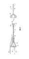
- FIG. 1shows a schematic diagram of an embodiment of an ablation system that includes a handle and a removable probe in accordance with the present disclosure
- FIG. 2shows a side, cutaway view of an ablation instrument having a handle and a removable probe in accordance with the present disclosure
- FIG. 3shows a schematic view of the relationship between components of an ablation instrument having a removable probe in accordance with the present disclosure
- FIG. 4shows an enlarged, cutaway view of a hub portion of an ablation instrument having a removable probe in accordance with the present disclosure
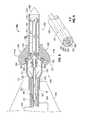
- FIG. 5shows an enlarged, cutaway view of a connector portion of an ablation instrument having a removable probe in accordance with the present disclosure
- FIG. 6shows a section view of a feedline of an ablation instrument having a removable probe in accordance with the present disclosure
- FIG. 7shows an enlarged, cutaway view of a tip portion of an ablation instrument having a removable probe in accordance with the present disclosure
- FIG. 8shows a side, cutaway view of another embodiment of a removable antenna assembly in accordance with the present disclosure
- FIG. 9shows a section view of the FIG. 8 removable antenna assembly
- FIG. 10shows a detailed side, cutaway view of a male connector of the FIG. 8 removable antenna assembly
- FIG. 11shows a detailed side, cutaway view of a female connector of the FIG. 8 removable antenna assembly
- proximalshall refer to the end of the instrument that is closer to the user, while the term “distal” shall refer to the end that is farther from the user.
- distalshall refer to the end that is farther from the user.
- terms referencing orientatione.g., “top”, “bottom”, “up”, “down”, “left”, “right”, “clockwise”, “counterclockwise”, and the like, are used for illustrative purposes with reference to the figures and features shown therein. It is to be understood that embodiments in accordance with the present disclosure may be practiced in any orientation without limitation.
- like-referenced numbersrepresent elements which may perform the same, similar, or equivalent functions.
- connector genderpresented herein are for illustrative purposes only, and embodiments are envisioned wherein the various components described can be any of male, female, hermaphroditic, or sexless gender.
- references to circular and coaxial connectorsare illustrative in nature, and other connector types, shapes and configurations are contemplated within the scope of the present disclosure.
- Electromagnetic energyis generally classified by increasing energy or decreasing wavelength into radio waves, microwaves, infrared, visible light, ultraviolet, X-rays and gamma-rays.
- microwavegenerally refers to electromagnetic waves in the frequency range of 300 megahertz (MHz) (3 ⁇ 10 8 cycles/second) to 300 gigahertz (GHz) (3 ⁇ 10 11 cycles/second).
- ablation proceduregenerally refers to any ablation procedure, such as microwave ablation, radio frequency (RF) ablation, or microwave ablation assisted resection.
- transmission linegenerally refers to any transmission medium that can be used for the propagation of signals from one point to another.
- Various embodiments of the present disclosureprovide electrosurgical devices operably associated with directional reflector assemblies for treating tissue and methods of directing electromagnetic radiation to a target volume of tissue.
- Embodimentsmay be implemented using electromagnetic radiation at microwave frequencies, or, at other frequencies.
- An electrosurgical system having an aperture assembly that includes an energy applicator operably associated with a directional reflector assembly, according to various embodiments,is configured to operate between about 300 MHz and about 10 GHz with a directional radiation pattern.
- Various embodiments of the presently disclosed electrosurgical devices, directional reflector assemblies, thereto and electrosurgical system including the sameare suitable for microwave ablation and for use to pre-coagulate tissue for microwave ablation assisted surgical resection.
- various methods described hereinbeloware targeted toward microwave ablation and the destruction and/or resection of targeted tissue, it is to be understood that methods for directing electromagnetic radiation may be used with other therapies in which the target tissue is partially destroyed, damaged, or dissected, such as, for example, to prevent the conduction of electrical impulses within heart tissue.
- teachings of the present disclosuremay apply to a dipole, monopole, helical, or other suitable type of microwave antenna.
- FIG. 1shows an ablation system 10 in accordance with an embodiment of the present disclosure.
- the ablation system 10includes an ablation instrument 12 that is operably connected by a cable 15 to connector 16 , which further operably connects instrument 12 to a generator assembly 14 .
- Generator assembly 14may be a source of ablation energy, e.g., microwave or RF energy in the range of about 915 MHz to about 10.0 GHz.
- Instrument 12is adapted for use in various surgical procedures and generally includes a handle assembly 30 configured to operably engage with an antenna probe 20 .
- a proximal end 23 of probe 20electromechanically engages a distal end 31 of handle 30 .
- Cable 15may additionally or alternatively provide a conduit (not explicitly shown in FIG. 1 ) configured to provide coolant from a coolant source 18 to ablation instrument 12 .
- an embodiment of an ablation instrument in accordance with the present disclosureincludes a handle 30 having a housing 32 .
- Housing 32may be assembled from a two piece (left and right half) clamshell-type assembly that is joined along a common edge by any suitable manner of attachment, e.g., laser welding, chemical welding, adhesive, mechanical fasteners, clips, threaded fasteners and the like.
- Housing 32includes a hub 34 that couples a handle feedline 70 with an input cable 60 , an inflow tube 40 and an outflow tube 41 .
- Hub 34includes a plenum 42 that receives spent coolant from a proximal end 46 of feedline outflow conduit 48 , and from which spent coolant flows into outflow tube 41 .
- Input cable 60includes an inner conductor 62 coaxially disposed within an outer conductor 64 having an insulator 63 disposed therebetween.
- Proximal feedline 70includes a number of elements arranged concentrically therein that are adapted to deliver electrosurgical energy and coolant to antenna probe 20 and to remove coolant from antenna probe 20 .
- Proximal feedline 70is formed from a feedline hypotube 51 that extends distally from a distal end 35 of hub 34 and terminates distally within male luer-style member 24 , as shown in FIG. 5 .
- Input cable 60extends through a proximal wall of hub 34 via sealed port 66 and continues through plenum 42 and a longitudinal axis of feedline hypotube 51 and terminates distally within male luer-style member 24 . As seen in FIG.
- input cable 60includes feedline inner conductor 62 disposed along a longitudinal axis thereof.
- a feedline insulator 63is coaxially disposed about feedline inner conductor 62 .
- a feedline outer conductor 64is disposed about feedline insulator 63 .
- a feedline coolant tube 50is concentrically disposed between feedline hypotube 51 and input cable 60 to form a feedline inflow conduit 47 and a feedline outflow conduit 48 .
- a proximal end 46 of feedline outflow conduit 48is in fluid communication with plenum 42 .
- a distal end 45 of inflow tube 40is in fluid communication with a proximal end of feedline inflow conduit 47 to provide coolant during use to antenna probe 20 .
- a seal 49is disposed at a proximal end of feedline coolant tube 50 to direct inflowing fresh coolant distally through feedline inflow conduit 47 and to prevent intermingling of inflowing fresh coolant with spent coolant exiting through feedline outflow conduit 48 .
- a distal end 65 of feedline inner conductor 62extends beyond a distal end of cable 60 and is adapted to engage an inner conductor connector 86 to facilitate the electrical coupling of feedline inner conductor 62 with a probe inner conductor 82 when antenna probe 20 is joined to handle 30 .
- Handle 30includes an actuator 71 , which may be a handswitch as shown, or, alternatively, and without limitation, a trigger switch, a pushbutton switch, a slide switch, a lever switch, that is configured to activate generator 14 when actuated by a surgeon.
- Actuator 71may be operably coupled to generator 14 by control cable 72 and/or control cable 73 .
- actuator 71includes a momentary-contact, single pole single throw (SPST) switch.
- SPSTmomentary-contact, single pole single throw
- actuator 71may include a snap dome switch.
- An interlock(not explicitly shown) may be included in handle 30 to inhibit actuation of generator 14 when no antenna probe 20 is coupled to handle 30 .
- Antenna probe 20includes a probe hypotube 81 shaft having an internal structure that generally corresponds to that of feedline hypotube 51 and includes features at a proximal end 23 thereof adapted to operatively engage a distal end of feedline hypotube 51 .
- Hypotube 81includes a probe inner conductor 82 that extends along a longitudinal axis of hypotube 81 .
- a probe insulator 83is coaxially-disposed about probe inner conductor 81
- a probe outer conductor 84is coaxially-disposed about insulator 83 .
- a probe coolant tube 80is concentrically-disposed between probe hypotube 81 and probe outer conductor 84 to form a probe inflow conduit 87 and a probe outflow conduit 88 .
- An inner conductor connector 86is operatively fixed to probe inner conductor 82 and is configured to operably engage feedline inner conductor 62 when antenna probe 20 is joined to handle 30 .
- inner conductor connector 86is configured as a female connector, however, inner conductor connector 86 may be a male connector, a hermaphroditic connector, or any other suitable form of connector.
- Probe outer conductor 84includes an outer conductor connector 85 operatively fixed to a proximal end thereof that is configured to operably engage a proximal end 66 of feedline outer conductor 64 when antenna probe 20 is joined to handle 30 .
- the conductor connectorsmay be joined to their respective conductors (e.g., inner conductor connector 86 to probe inner conductor 82 , and outer conductor connector 85 to outer conductor 84 ) by any suitable manner of electromechanical bonding, including without limitation soldering, brazing, welding, crimping, or threaded fastener.
- An outer conductor insulator(not explicitly shown) may be coaxially disposed about feedline outer conductor 64 and/or probe outer conductor 84 .
- a proximal end of probe hypotube 81includes a hypotube flared section 89 that is configured to form a fluid-tight connection around a distal end of feedline hypotube 51 .
- a proximal end of probe coolant tube 80includes a coolant tube flared section 90 that is configured to form a fluid-tight connection around a distal end of feedline coolant tube 50 .
- the mating surfaces between feedline hypotube 51 and hypotube flared section 89 , and between feedline coolant tube 50 and coolant tube flared section 90may include seal-enhancing elements (not explicitly shown), including without limitation an o-ring, elastomeric coating, a lubricious coating, or a series of interlocking ridges.
- the flared sectionsi.e., hypotube flared section 89 and/or coolant tube flared section 90
- the flared sectionsmay be configured to expand upon the insertion of the corresponding mating proximal component, i.e., feedline hypotube 51 and/or feedline coolant tube 50 , respectively, which, in turn, provides improved sealing between the joined components.
- the handle 30 and antenna probeinclude coupling elements 24 and 22 , respectively, that are adapted to operatively couple handle 30 and probe 20 . More particularly, and as seen in FIGS. 5 and 6 , handle 30 includes a male luer-style member 24 that is configured to operably engage a female luer-style collar 22 . When coupled, an outer mating surface 25 of male luer member 24 engages an inner mating surface 26 of female luer collar 22 to retain antenna probe 20 to handle 30 in a fixed relationship. In an embodiment, male luer member 24 engages an inner mating surface 26 of female luer collar 22 by frictional retention.
- male luer member 24engages female luer collar 22 by any suitable manner of connection, including without limitation, threaded engagement, bayonet mount (e.g., “half-twist” connector), quick disconnect connector (MPT-FTP pair), and the like.
- bayonet mounte.g., “half-twist” connector
- MPT-FTP pairquick disconnect connector
- coupling elements 24 and 22are male and female couplers, respectively, embodiments in accordance with the present disclosure may utilize any combination of cooperative male, female, and hermaphroditic couplers 24 and 22 to effectuate operative coupling of handle 30 and probe 20 .
- hypotube 81extends distally and includes a distal tip 21 having a contour configured to facilitate piercing of tissue.
- tip 21includes a generally conical tapered section 99 , however, other tip configurations are within the scope of the present disclosure, including without limitation, chisel tip, flat tip, spoon tip, and so forth.
- a cooling chamber 92is defined within tip 21 to facilitate the circulation of coolant therein and to control the temperature of probe 20 .
- a distal end 93 of probe coolant tube 80defines a coolant inflow port 94 through which coolant flows form probe inflow conduit 87 into coolant chamber 92 .
- a distal end 93 of probe coolant tube 80also defines coolant outflow port 95 , that is arranged generally concentrically about coolant inflow port 94 , and through which spent coolant flows from coolant chamber 92 proximally into probe outflow conduit 88 .
- Probe insulator 83 and probe inner conductor 82extend distally beyond a distal end 93 of coolant tube 80 and/or a distal end 96 of probe outer conductor 84 into cooling chamber 92 .
- a distal end 100 of inner conductor 82extends distally beyond a distal end 97 of probe insulator 83 into distal radiating section 91 .
- Distal radiating section 91is electromechanically coupled to a distal end 100 of probe inner conductor by any suitable manner of attachment, including without limitation soldering, welding, brazing, crimping, and the like.
- a quarter wave balun 98may be coaxially disposed about outer conductor 98 to form a quarter-wave short-circuiting balun adapted to contain the radiated microwave energy to the region of tip 21 .
- An ablation probe 20 in accordance with the present disclosuremay have a length L that ranges from about 1 cm to about 1 m in length. During a surgical procedure, a surgeon may elect to use one or more ablation probes, in one or more lengths, in order to achieve the desired surgical outcome.
- the diameter D of an ablation probe in accordance with the present disclosuremay have a range of about 0.1 mm to about 10 mm.
- a kit that includes a handle assembly 30 and a plurality of ablation probes 20may be provided to a surgeon.
- the quantity, length, and/or diameter of the ablation probes provided in the kitmay be based at least in part by a particular surgical procedure for which the kit may be suited.
- the kitmay be provided in sterile packaging to ensure the handle 30 and probes 20 are provided to the surgical site free of biocontaminants.
- An antenna assembly 200includes a handle-side coupler 240 and an antenna probe 280 .
- a proximal end 284 of probe 280may be selectively and releasably engageable with the handle assembly 231 or a portion thereof, e.g., coupler 240 .
- Antenna probe 280may be considered disposable, reusable, and may be referred to by the portmanteau “reposable.” Accordingly, a new or different probe 280 may selectively replace a prior-coupled probe 280 as required.
- Hypotube 210is fixed within a handle 230 .
- Hypotube 230may be formed from any suitable material capable of delivering fluid and/or capable of conducting electricity, such as without limitation, stainless steel.
- Hypotube 201may be operably coupled to a source of electrosurgical energy by a conductor 264 .
- Coupler 240includes a male connector 224 that is fixed to a distal end 231 of handle 230 .
- Male connector 224may be a luer-style connector formed from an electrically conductive, rigid material including without limitation, stainless steel.
- Male connector 224is electrically coupled to hypotube 201 .
- the combination of conductor 264 , hypotube 201 , and/or connector 224are adapted to deliver electrosurgical energy to probe 280 , as will be further described in detail below.
- Connector 225includes a proximal base portion 228 having a diameter that is configured to fixably engage hypotube 201 around an outer diameter thereof to form an electrically-conductive and fluid-tight connection therewith.
- Proximal base portion 228 of connector 224may extend proximally into handle 230 , which may increase the ridigity and junction strength of the overall antenna assembly 200 .
- a flared distal portion 226 of connector 224 having a diameter greater than that of proximal base portion 228forms an internal plenum volume 227 to accommodate the flow of coolant exiting from antenna probe 280 , and includes a distal rim 225 configured to selectively engage a corresponding circumferential saddle 285 defined within a female connector 282 that is fixed at a proximal end 284 of probe 280 .
- a coolant tube 202is positioned concentrically within hypotube 201 .
- the inner portion of coolant tube 202defines an inflow conduit 207 that is adapted to deliver coolant from a coolant source (not explicitly shown in this view), that may be operably coupled to a proximal end of coolant tube 202 , to probe assembly 280 .
- An outflow conduit 208is defined by the coaxial arrangement of coolant tube 202 and hypotube 201 , and is in fluid communication with plenum 277 to receive spent coolant exiting from probe 280 .
- Coolant tube 202may be formed from any suitable material, however it is envisioned coolant tube 202 is formed from conductive material.
- Coolant tube 202may be operably coupled to a source of electrosurgical energy by a conductor 262 . By this arrangement, coolant tube 202 may be adapted to provide electrosurgical energy to probe 280 . Coolant tube 202 extends distally to about a plane defined by a distal rim 225 of connector 224 .
- Probe 280includes a number of features designed to facilitate the selective operable engagement with coupler 240 .
- Female coupler 250includes a female connector 282 that is fixed to a proximal end 284 of probe 280 .
- Female connector 282may be a luer-style connector formed from an electrically conductive, rigid material including without limitation, stainless steel.
- Female connector 282is electrically coupled to probe hypotube 281 .
- Female connector 282 and/or probe hypotube 281may be formed from any suitable electrically-conductive, high-strength, temperature resistant material, such as without limitation, stainless steel.
- a distal end of probe hypotube 281includes a trocar tip 299 that has a generally tapered shape, e.g., conical, to facilitate the penetration thereof, and probe 280 generally, into tissue.
- a circumferential saddle 285is defined within female connector 282 and configured to selectively operably engage rim 225 of connector 224 to facilitate the electromechanical coupling of probe 280 to handle 230 .
- Saddle 285 and rim 225may engage using any suitable manner of engagement, including without limitation a snap fit, interference fit, cooperating threaded engagement, or a bayonet (e.g., “half-twist”) coupling.
- the combination of connector 224 and connector 282enables the conduction of electrosurgical energy therethrough.
- Probe 280includes a generally tubular antenna element 293 concentrically disposed within probe hypotube 281 .
- a proximal end of antenna element 293includes a female barrel coupler 290 that is configured to operably engage a distal end 203 of coolant tube 202 .
- a distal end of antenna element 293may include a flared opening 294 , though which coolant exiting from inflow conduit 287 flows into a cooling chamber 291 defined within probe hypotube 281 .
- Barrel coupler 290may be integrally formed with antenna element 293 , by, e.g., forging, cold rolling, or machining, or may be separately fabricated and joined to antenna element 293 by, e.g., welding, brazing, soldering, crimping, and/or by threaded fastening.
- An o-ring 289 or other form of resilient sealis retained within barrel connector 290 to promote a fluid-tight connection between coolant tube 202 and antenna element 293 , and to isolate spent coolant in and around the region of plenum 227 from the inflow conduits 207 and/or 287 .
- Barrel connector 290may include one or more crimps or serrations 283 configured to retain o-ring 289 in place.
- Spacer 286may be included within probe hypotube 281 and adapted to center antenna element 293 within hypotube 281 .
- Spacer 286includes one or more support legs 292 extending radially from a central hub 295 .
- Central hub 295is configured to retain antenna element 293 centrally within probe hypotube 281 to, e.g., define outflow conduit 288 , to prevent short circuits between antenna element 293 and hypotube 281 , and to promote secure engagement between barrel coupler 290 and coolant tube 202 .
- Spacer 286may be formed from any suitable fluid- and temperature-resistant electrically insulative material.
- a thermosetting polymersuch as without limitation, polyimid, may be advantageously used to form spacer 286 .
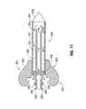
- FIGS. 12A-12Fa method of performing an ablation procedure on targeted tissue T is illustrated.
- a surgeondetermines, based on operative requirements, the number, size (e.g., length and diameter), and placement of the ablation probes 20 .
- a plurality of probes 20 , 20 ′, 20 ′′ . . . 20 nare inserted into targeted tissue T.
- the probes 20may be of differing lengths and diameters as required.
- Handle 30is also operatively coupled to a generator 14 and may, additionally, be operatively coupled to a coolant source 18 as described hereinabove.
- a surgeonmay bring a handle 30 into axial alignment with a first probe with which ablation energy is delivered to tissue T.
- a surgeonaligns the handle 30 with first probe 20 such that male luer member 24 is positioned to engage female luer collar 22 , mates the male luer member 24 to the female luer collar 22 , and secures male luer member 24 to female luer collar 22 to form an ablation instrument 12 in accordance with the present disclosure.
- male luer member 24may be secured to female luer collar 22 by twisting, threading, or otherwise manipulating the engaging portions thereof accordingly to affectuate engagement.
- the surgeonmay then activate the generator 14 to deliver ablation energy to tissue T as shown in FIG. 12D .
- the activation of generator 14may additionally activate the delivery of coolant from coolant source 18 through instrument 12 .
- the generator 14(and delivery of coolant, if activated) is deactivated
- the surgeonmay then de-couple handle 30 from ablation probe 20 , and couple handle 30 to a subsequent probe 20 ′, and ablation energy applied to the second probe 20 ′.
- the procedureis repeated as required with each successive ablation probe 20 ′′ . . . 20 n as illustrated by FIGS. 12E and 12F until each probe 20 et seq. has delivered ablation energy to tissue T.
Landscapes
- Health & Medical Sciences (AREA)
- Surgery (AREA)
- Life Sciences & Earth Sciences (AREA)
- Biomedical Technology (AREA)
- Medical Informatics (AREA)
- Nuclear Medicine, Radiotherapy & Molecular Imaging (AREA)
- Electromagnetism (AREA)
- Engineering & Computer Science (AREA)
- Physics & Mathematics (AREA)
- Heart & Thoracic Surgery (AREA)
- Otolaryngology (AREA)
- Molecular Biology (AREA)
- Animal Behavior & Ethology (AREA)
- General Health & Medical Sciences (AREA)
- Public Health (AREA)
- Veterinary Medicine (AREA)
- Surgical Instruments (AREA)
Abstract
Description
Claims (18)
Priority Applications (9)
| Application Number | Priority Date | Filing Date | Title |
|---|---|---|---|
| US13/083,185US9579150B2 (en) | 2011-04-08 | 2011-04-08 | Microwave ablation instrument with interchangeable antenna probe |
| JP2012087246AJP5894840B2 (en) | 2011-04-08 | 2012-04-06 | Microwave ablation device with compatible antenna probe |
| CN201510927309.XACN105326564B (en) | 2011-04-08 | 2012-04-09 | Microwave ablation device with interchangeable antenna detector |
| CN201210169145.5ACN102727306B (en) | 2011-04-08 | 2012-04-09 | Microwave ablation device with interchangeable antenna probes |
| EP15163674.3AEP2926758B1 (en) | 2011-04-08 | 2012-04-10 | Microwave ablation instrument with interchangeable antenna probe |
| AU2012202042AAU2012202042B2 (en) | 2011-04-08 | 2012-04-10 | Microwave ablation instrument with interchangeable antenna probe |
| EP12002536.6AEP2508145B1 (en) | 2011-04-08 | 2012-04-10 | Ablation system with interchangeable antenna probe |
| CA2773415ACA2773415A1 (en) | 2011-04-08 | 2012-04-10 | Microwave ablation instrument with interchangeable antenna probe |
| US15/444,525US10610298B2 (en) | 2011-04-08 | 2017-02-28 | Microwave ablation instrument with interchangeable antenna probe |
Applications Claiming Priority (1)
| Application Number | Priority Date | Filing Date | Title |
|---|---|---|---|
| US13/083,185US9579150B2 (en) | 2011-04-08 | 2011-04-08 | Microwave ablation instrument with interchangeable antenna probe |
Related Child Applications (1)
| Application Number | Title | Priority Date | Filing Date |
|---|---|---|---|
| US15/444,525ContinuationUS10610298B2 (en) | 2011-04-08 | 2017-02-28 | Microwave ablation instrument with interchangeable antenna probe |
Publications (2)
| Publication Number | Publication Date |
|---|---|
| US20120259329A1 US20120259329A1 (en) | 2012-10-11 |
| US9579150B2true US9579150B2 (en) | 2017-02-28 |
Family
ID=46045629
Family Applications (2)
| Application Number | Title | Priority Date | Filing Date |
|---|---|---|---|
| US13/083,185Expired - Fee RelatedUS9579150B2 (en) | 2011-04-08 | 2011-04-08 | Microwave ablation instrument with interchangeable antenna probe |
| US15/444,525Active2032-12-21US10610298B2 (en) | 2011-04-08 | 2017-02-28 | Microwave ablation instrument with interchangeable antenna probe |
Family Applications After (1)
| Application Number | Title | Priority Date | Filing Date |
|---|---|---|---|
| US15/444,525Active2032-12-21US10610298B2 (en) | 2011-04-08 | 2017-02-28 | Microwave ablation instrument with interchangeable antenna probe |
Country Status (6)
| Country | Link |
|---|---|
| US (2) | US9579150B2 (en) |
| EP (2) | EP2508145B1 (en) |
| JP (1) | JP5894840B2 (en) |
| CN (2) | CN105326564B (en) |
| AU (1) | AU2012202042B2 (en) |
| CA (1) | CA2773415A1 (en) |
Cited By (8)
| Publication number | Priority date | Publication date | Assignee | Title |
|---|---|---|---|---|
| US10022186B2 (en) | 2008-08-28 | 2018-07-17 | Covidien Lp | Microwave antenna with cooled handle |
| US20180360529A1 (en)* | 2017-06-19 | 2018-12-20 | Covidien Lp | Microwave and radiofrequency energy-transmitting tissue ablation systems |
| US10271902B2 (en) | 2012-01-06 | 2019-04-30 | Covidien Lp | System and method for treating tissue using an expandable antenna |
| US10405918B2 (en) | 2012-04-30 | 2019-09-10 | Covidien Lp | Limited reuse ablation needles and ablation devices for use therewith |
| US10610298B2 (en) | 2011-04-08 | 2020-04-07 | Covidien Lp | Microwave ablation instrument with interchangeable antenna probe |
| US10631922B2 (en) | 2008-02-07 | 2020-04-28 | Covidien Lp | Endoscopic instrument for tissue identification |
| US20200197089A1 (en)* | 2018-12-19 | 2020-06-25 | Boston Scientific Scimed, Inc. | Irrigation cooling structure for microwave ablation tissue probe |
| US11147622B2 (en) | 2011-03-09 | 2021-10-19 | Covidien Lp | Systems for thermal-feedback-controlled rate of fluid flow to fluid-cooled antenna assembly and methods of directing energy to tissue using same |
Families Citing this family (25)
| Publication number | Priority date | Publication date | Assignee | Title |
|---|---|---|---|---|
| US8246615B2 (en) | 2009-05-19 | 2012-08-21 | Vivant Medical, Inc. | Tissue impedance measurement using a secondary frequency |
| US8292881B2 (en) | 2009-05-27 | 2012-10-23 | Vivant Medical, Inc. | Narrow gauge high strength choked wet tip microwave ablation antenna |
| US9055957B2 (en)* | 2010-12-23 | 2015-06-16 | Covidien Lp | Microwave field-detecting needle assemblies, methods of manufacturing same, methods of adjusting an ablation field radiating into tissue using same, and systems including same |
| US8888771B2 (en) | 2011-07-15 | 2014-11-18 | Covidien Lp | Clip-over disposable assembly for use with hemostat-style surgical instrument and methods of manufacturing same |
| US9314370B2 (en) | 2011-09-28 | 2016-04-19 | Zoll Circulation, Inc. | Self-centering patient temperature control catheter |
| WO2014165042A1 (en)* | 2013-03-13 | 2014-10-09 | Advanced Cooling Therapy, Llc | Devices, systems, and methods for managing patient temperature and correcting cardiac arrhythmia |
| US9119650B2 (en) | 2013-03-15 | 2015-09-01 | Covidien Lp | Microwave energy-delivery device and system |
| US9161814B2 (en)* | 2013-03-15 | 2015-10-20 | Covidien Lp | Microwave energy-delivery device and system |
| US9301723B2 (en) | 2013-03-15 | 2016-04-05 | Covidien Lp | Microwave energy-delivery device and system |
| WO2015042900A1 (en) | 2013-09-29 | 2015-04-02 | Covidien Lp | Medical treatment devices having adjustable length and/or diameter |
| WO2015042906A1 (en) | 2013-09-29 | 2015-04-02 | Covidien Lp | Medical treatment devices having adjustable length and/or diameter |
| US10342566B2 (en)* | 2016-03-29 | 2019-07-09 | Covidien Lp | Devices, systems, and methods for cooling a surgical instrument |
| CN105816240B (en)* | 2016-05-24 | 2018-09-28 | 赛诺微医疗科技(浙江)有限公司 | For the antenna module of microwave ablation and using its microwave melt needle |
| IT201600113574A1 (en)* | 2016-11-10 | 2018-05-10 | Elesta S R L | LASER THERMO-WELDING DEVICE WITH CENTERING MEANS AND EQUIPMENT INCLUDING THE DEVICE |
| EP3545889A1 (en)* | 2018-03-29 | 2019-10-02 | National University of Ireland Galway | An ablation probe |
| EP3381393A1 (en)* | 2017-03-31 | 2018-10-03 | National University of Ireland Galway | An ablation probe |
| WO2019095272A1 (en)* | 2017-11-17 | 2019-05-23 | 赛诺微医疗科技(浙江)有限公司 | Microwave signal suppression device and method, antenna assembly, and microwave ablation needle |
| EP3773293A1 (en)* | 2018-03-29 | 2021-02-17 | National University of Ireland Galway | An ablation probe |
| CN108670405A (en)* | 2018-05-25 | 2018-10-19 | 南通融锋医疗科技有限公司 | A non-puncturing microwave ablation antenna and its application |
| WO2021026471A2 (en) | 2019-08-07 | 2021-02-11 | Biocompatibles Uk Limited | Microwave ablation probe |
| GB2594946B (en)* | 2020-05-12 | 2025-01-22 | Gyrus Medical Ltd | RF Shaver connector |
| US20230414281A1 (en)* | 2022-06-24 | 2023-12-28 | Varian Medical Systems, Inc. | Fluid-cooled low-profile microwave ablation probe with spherical ablation zone |
| CN116636922B (en)* | 2023-05-12 | 2024-05-03 | 心诺普医疗技术(北京)有限公司 | Magnetic induction thermal ablation balloon catheter and ablation method |
| CN118217004B (en)* | 2024-03-22 | 2024-10-01 | 南京康友医疗科技有限公司 | Flexible microwave ablation catheter |
| CN119174644B (en)* | 2024-11-26 | 2025-09-05 | 上海方润医疗科技股份有限公司 | Ablation electrode device with optimized internal structure of handle |
Citations (177)
| Publication number | Priority date | Publication date | Assignee | Title |
|---|---|---|---|---|
| DE390937C (en) | 1922-10-13 | 1924-03-03 | Adolf Erb | Device for internal heating of furnace furnaces for hardening, tempering, annealing, quenching and melting |
| DE1099658B (en) | 1959-04-29 | 1961-02-16 | Siemens Reiniger Werke Ag | Automatic switch-on device for high-frequency surgical devices |
| FR1275415A (en) | 1960-09-26 | 1961-11-10 | Device for detecting disturbances for electrical installations, in particular electrosurgery | |
| DE1139927B (en) | 1961-01-03 | 1962-11-22 | Friedrich Laber | High-frequency surgical device |
| DE1149832B (en) | 1961-02-25 | 1963-06-06 | Siemens Reiniger Werke Ag | High frequency surgical apparatus |
| FR1347865A (en) | 1962-11-22 | 1964-01-04 | Improvements to diathermo-coagulation devices | |
| DE1439302A1 (en) | 1963-10-26 | 1969-01-23 | Siemens Ag | High-frequency surgical device |
| US3439680A (en) | 1965-04-12 | 1969-04-22 | Univ Northwestern | Surgical instrument for cataract removal |
| SU401367A1 (en) | 1971-10-05 | 1973-10-12 | Тернопольский государственный медицинский институт | BIAKTIVNYE ELECTRO SURGICAL INSTRUMENT |
| DE2439587A1 (en) | 1973-08-23 | 1975-02-27 | Matburn Holdings Ltd | ELECTROSURGICAL DEVICE |
| DE2455174A1 (en) | 1973-11-21 | 1975-05-22 | Termiflex Corp | INPUT / OUTPUT DEVICE FOR DATA EXCHANGE WITH DATA PROCESSING DEVICES |
| DE2407559A1 (en) | 1974-02-16 | 1975-08-28 | Dornier System Gmbh | Tissue heat treatment probe - has water cooling system which ensures heat development only in treated tissues |
| DE2415263A1 (en) | 1974-03-29 | 1975-10-02 | Aesculap Werke Ag | Surgical H.F. coagulation probe has electrode tongs - with exposed ends of insulated conductors forming tong-jaws |
| DE2429021A1 (en) | 1974-06-18 | 1976-01-08 | Erbe Elektromedizin | Remote control for HF surgical instruments - uses cable with two conductors at most |
| US3938527A (en) | 1973-07-04 | 1976-02-17 | Centre De Recherche Industrielle De Quebec | Instrument for laparoscopic tubal cauterization |
| FR2235669B1 (en) | 1973-07-07 | 1976-05-07 | Lunacek Boris | |
| DE2460481A1 (en) | 1974-12-20 | 1976-06-24 | Delma Elektro Med App | Electrode grip for remote HF surgical instrument switching - has shaped insulated piece with contact ring of sterilizable (silicon) rubber |
| DE2602517A1 (en) | 1975-01-23 | 1976-07-29 | Dentsply Int Inc | ELECTROSURGICAL DEVICE |
| DE2504280A1 (en) | 1975-02-01 | 1976-08-05 | Hans Heinrich Prof Dr Meinke | DEVICE FOR ELECTRIC TISSUE CUTTING IN SURGERY |
| DE2627679A1 (en) | 1975-06-26 | 1977-01-13 | Marcel Lamidey | HEMATISTIC HIGH FREQUENCY EXTRACTOR FORCEPS |
| DE2540968A1 (en) | 1975-09-13 | 1977-03-17 | Erbe Elektromedizin | Circuit for bipolar coagulation tweezers - permits preparation of tissues prior to coagulation |
| FR2276027B3 (en) | 1974-06-25 | 1977-05-06 | Medical Plastics Inc | |
| DE2820908A1 (en) | 1977-05-16 | 1978-11-23 | Joseph Skovajsa | DEVICE FOR THE LOCAL TREATMENT OF A PATIENT IN PARTICULAR FOR ACUPUNCTURE OR AURICULAR THERAPY |
| DE2803275A1 (en) | 1978-01-26 | 1979-08-02 | Aesculap Werke Ag | HF surgical appts. with active treatment and patient electrodes - has sensor switching generator to small voltage when hand-operated switch is closed |
| DE2823291A1 (en) | 1978-05-27 | 1979-11-29 | Rainer Ing Grad Koch | Coagulation instrument automatic HF switching circuit - has first lead to potentiometer and second to transistor base |
| SU727201A2 (en) | 1977-11-02 | 1980-04-15 | Киевский Научно-Исследовательский Институт Нейрохирургии | Electric surgical apparatus |
| FR2313708B1 (en) | 1975-06-02 | 1980-07-04 | Sybron Corp | |
| DE2946728A1 (en) | 1979-11-20 | 1981-05-27 | Erbe Elektromedizin GmbH & Co KG, 7400 Tübingen | HF surgical appts. for use with endoscope - provides cutting or coagulation current at preset intervals and of selected duration |
| USD263020S (en) | 1980-01-22 | 1982-02-16 | Rau Iii David M | Retractable knife |
| DE3143421A1 (en) | 1980-11-04 | 1982-05-27 | The Agency of Industrial Science and Technology, Tokyo | Laser scalpel |
| DE3045996A1 (en) | 1980-12-05 | 1982-07-08 | Medic Eschmann Handelsgesellschaft für medizinische Instrumente mbH, 2000 Hamburg | Electro-surgical scalpel instrument - has power supply remotely controlled by surgeon |
| USD266842S (en) | 1980-06-27 | 1982-11-09 | Villers Mark W | Phonograph record spacer |
| DE3120102A1 (en) | 1981-05-20 | 1982-12-09 | F.L. Fischer GmbH & Co, 7800 Freiburg | ARRANGEMENT FOR HIGH-FREQUENCY COAGULATION OF EGG WHITE FOR SURGICAL PURPOSES |
| FR2517953A1 (en) | 1981-12-10 | 1983-06-17 | Alvar Electronic | Diaphanometer for optical examination of breast tissue structure - measures tissue transparency using two plates and optical fibre bundle cooperating with photoelectric cells |
| USD278306S (en) | 1980-06-30 | 1985-04-09 | Mcintosh Lois A | Microwave oven rack |
| FR2502935B1 (en) | 1981-03-31 | 1985-10-04 | Dolley Roger | METHOD AND DEVICE FOR CONTROLLING THE COAGULATION OF TISSUES USING A HIGH FREQUENCY CURRENT |
| DE3510586A1 (en) | 1985-03-23 | 1986-10-02 | Erbe Elektromedizin GmbH, 7400 Tübingen | Control device for a high-frequency surgical instrument |
| FR2573301B3 (en) | 1984-11-16 | 1987-04-30 | Lamidey Gilles | SURGICAL PLIERS AND ITS CONTROL AND CONTROL APPARATUS |
| DE3604823A1 (en) | 1986-02-15 | 1987-08-27 | Flachenecker Gerhard | HIGH FREQUENCY GENERATOR WITH AUTOMATIC PERFORMANCE CONTROL FOR HIGH FREQUENCY SURGERY |
| EP0246350A1 (en) | 1986-05-23 | 1987-11-25 | Erbe Elektromedizin GmbH. | Coagulation electrode |
| DE8712328U1 (en) | 1987-09-11 | 1988-02-18 | Jakoubek, Franz, 7201 Emmingen-Liptingen | Endoscopy forceps |
| USD295894S (en) | 1985-09-26 | 1988-05-24 | Acme United Corporation | Disposable surgical scissors |
| USD295893S (en) | 1985-09-25 | 1988-05-24 | Acme United Corporation | Disposable surgical clamp |
| DE3711511C1 (en) | 1987-04-04 | 1988-06-30 | Hartmann & Braun Ag | Method for determining gas concentrations in a gas mixture and sensor for measuring thermal conductivity |
| DE3904558A1 (en) | 1989-02-15 | 1990-08-23 | Flachenecker Gerhard | Radio-frequency generator with automatic power control for radio-frequency surgery |
| DE3942998A1 (en) | 1989-12-27 | 1991-07-04 | Delma Elektro Med App | Electro-surgical HF instrument for contact coagulation - has monitoring circuit evaluating HF voltage at electrodes and delivering switch=off signal |
| JPH055106Y2 (en) | 1986-02-28 | 1993-02-09 | ||
| DE4238263A1 (en) | 1991-11-15 | 1993-05-19 | Minnesota Mining & Mfg | Adhesive comprising hydrogel and crosslinked polyvinyl:lactam - is used in electrodes for biomedical application providing low impedance and good mechanical properties when water and/or moisture is absorbed from skin |
| EP0521264A3 (en) | 1991-07-03 | 1993-06-16 | W.L. Gore & Associates Gmbh | Antenna device with feed |
| EP0556705A1 (en) | 1992-02-20 | 1993-08-25 | DELMA ELEKTRO-UND MEDIZINISCHE APPARATEBAU GESELLSCHAFT mbH | High frequency surgery device |
| EP0558429A1 (en) | 1992-02-26 | 1993-09-01 | PECHINEY RECHERCHE (Groupement d'Intérêt Economique géré par l'ordonnance no. 67-821 du 23 Septembre 1967) | Method of simultaneous measuring of electrical resistivety and thermal conductivity |
| JPH0540112Y2 (en) | 1987-03-03 | 1993-10-12 | ||
| US5312400A (en) | 1992-10-09 | 1994-05-17 | Symbiosis Corporation | Cautery probes for endoscopic electrosurgical suction-irrigation instrument |
| US5336220A (en) | 1992-10-09 | 1994-08-09 | Symbiosis Corporation | Tubing for endoscopic electrosurgical suction-irrigation instrument |
| US5348554A (en) | 1992-12-01 | 1994-09-20 | Cardiac Pathways Corporation | Catheter for RF ablation with cooled electrode |
| JPH06343644A (en) | 1993-05-04 | 1994-12-20 | Gyrus Medical Ltd | Surgical peritoneoscope equipment |
| USD354218S (en) | 1992-10-01 | 1995-01-10 | Fiberslab Pty Limited | Spacer for use in concrete construction |
| DE4303882C2 (en) | 1993-02-10 | 1995-02-09 | Kernforschungsz Karlsruhe | Combination instrument for separation and coagulation for minimally invasive surgery |
| CN1103807A (en) | 1993-11-17 | 1995-06-21 | 刘中一 | Multi-frequency micro-wave therapeutic instrument |
| JPH07265328A (en) | 1993-11-01 | 1995-10-17 | Gyrus Medical Ltd | Electrode assembly for electric surgery device and electric surgery device using it |
| JPH0856955A (en) | 1994-06-29 | 1996-03-05 | Gyrus Medical Ltd | Electric surgical apparatus |
| JPH08252263A (en) | 1994-12-21 | 1996-10-01 | Gyrus Medical Ltd | Electronic surgical incision instrument and electronic surgical incision device using the same |
| WO1996034571A1 (en) | 1995-05-04 | 1996-11-07 | Cosman Eric R | Cool-tip electrode thermosurgery system |
| DE29616210U1 (en) | 1996-09-18 | 1996-11-14 | Olympus Winter & Ibe Gmbh, 22045 Hamburg | Handle for surgical instruments |
| JPH09492A (en) | 1995-06-21 | 1997-01-07 | Olympus Optical Co Ltd | Treatment tool inserting and detaching device for endoscope |
| JPH0910223A (en) | 1995-06-23 | 1997-01-14 | Gyrus Medical Ltd | Generator and system for electric operation |
| JPH09500804A (en) | 1993-07-27 | 1997-01-28 | マイクロスリス リミテッド | Treatment equipment |
| US5599346A (en) | 1993-11-08 | 1997-02-04 | Zomed International, Inc. | RF treatment system |
| US5609151A (en) | 1994-09-08 | 1997-03-11 | Medtronic, Inc. | Method for R-F ablation |
| DE19608716C1 (en) | 1996-03-06 | 1997-04-17 | Aesculap Ag | Bipolar surgical holding instrument |
| WO1997024074A1 (en) | 1995-12-29 | 1997-07-10 | Microgyn, Inc. | Apparatus and method for electrosurgery |
| US5674218A (en) | 1990-09-26 | 1997-10-07 | Cryomedical Sciences, Inc. | Cryosurgical instrument and system and method of cryosurgery |
| EP0836868A2 (en) | 1996-10-18 | 1998-04-22 | Gebr. Berchtold GmbH & Co. | High frequency surgical apparatus and method for operating same |
| DE19751106A1 (en) | 1996-11-27 | 1998-05-28 | Eastman Kodak Co | Laser printer with array of laser diodes |
| DE19717411A1 (en) | 1997-04-25 | 1998-11-05 | Aesculap Ag & Co Kg | Monitoring of thermal loading of patient tissue in contact region of neutral electrode of HF treatment unit |
| DE19751108A1 (en) | 1997-11-18 | 1999-05-20 | Beger Frank Michael Dipl Desig | Electrosurgical operation tool, especially for diathermy |
| DE19801173C1 (en) | 1998-01-15 | 1999-07-15 | Kendall Med Erzeugnisse Gmbh | Clamp connector for film electrodes |
| JPH11244298A (en) | 1997-12-19 | 1999-09-14 | Gyrus Medical Ltd | Electric surgical instrument |
| USD424693S (en) | 1999-04-08 | 2000-05-09 | Pruter Rick L | Needle guide for attachment to an ultrasound transducer probe |
| USD424694S (en) | 1998-10-23 | 2000-05-09 | Sherwood Services Ag | Forceps |
| USD425201S (en) | 1998-10-23 | 2000-05-16 | Sherwood Services Ag | Disposable electrode assembly |
| DE19848540A1 (en) | 1998-10-21 | 2000-05-25 | Reinhard Kalfhaus | Circuit layout and method for operating a single- or multiphase current inverter connects an AC voltage output to a primary winding and current and a working resistance to a transformer's secondary winding and current. |
| WO2000054682A1 (en) | 1999-03-17 | 2000-09-21 | Ntero Surgical, Inc. | Systems and methods for reducing post-surgical complications |
| US6139570A (en)* | 1997-05-19 | 2000-10-31 | Gynelab Products, Inc. | Disposable bladder for intrauterine use |
| US6146380A (en) | 1998-01-09 | 2000-11-14 | Radionics, Inc. | Bent tip electrical surgical probe |
| JP2000342599A (en) | 1999-05-21 | 2000-12-12 | Gyrus Medical Ltd | Generator for electrosurgical operation, electrosurgical operation system, method for operating this system and method for performing amputation and resection of tissue by electrosurgical operation |
| JP2000350732A (en) | 1999-05-21 | 2000-12-19 | Gyrus Medical Ltd | Electrosurgical system, generator for electrosurgery, and method for cutting or excising tissue by electrosurgery |
| US6162216A (en) | 1998-03-02 | 2000-12-19 | Guziak; Robert Andrew | Method for biopsy and ablation of tumor cells |
| JP2001008944A (en) | 1999-05-28 | 2001-01-16 | Gyrus Medical Ltd | Electric surgical signal generator and electric surgical system |
| JP2001029356A (en) | 1999-06-11 | 2001-02-06 | Gyrus Medical Ltd | Electric and surgical signal generator |
| JP2001128990A (en) | 1999-05-28 | 2001-05-15 | Gyrus Medical Ltd | Electro surgical instrument and electrosurgical tool converter |
| DE4339049C2 (en) | 1993-11-16 | 2001-06-28 | Erbe Elektromedizin | Surgical system configuration facility |
| JP2001231870A (en) | 2000-02-23 | 2001-08-28 | Olympus Optical Co Ltd | Moisturizing treatment apparatus |
| US20010025174A1 (en)* | 1996-03-29 | 2001-09-27 | Daniel Steven A. | Viewing surgical scope for minimally invasive procedures |
| USD449886S1 (en) | 1998-10-23 | 2001-10-30 | Sherwood Services Ag | Forceps with disposable electrode |
| US20020019627A1 (en)* | 2000-06-13 | 2002-02-14 | Maguire Mark A. | Surgical ablation probe for forming a circumferential lesion |
| WO2001074252A3 (en) | 2000-03-31 | 2002-05-23 | Rita Medical Systems Inc | Tissue biopsy and treatment apparatus and method |
| USD457959S1 (en) | 2001-04-06 | 2002-05-28 | Sherwood Services Ag | Vessel sealer |
| USD457958S1 (en) | 2001-04-06 | 2002-05-28 | Sherwood Services Ag | Vessel sealer and divider |
| US6402742B1 (en) | 1997-04-11 | 2002-06-11 | United States Surgical Corporation | Controller for thermal treatment of tissue |
| US6526320B2 (en) | 1998-11-16 | 2003-02-25 | United States Surgical Corporation | Apparatus for thermal treatment of tissue |
| EP1159926A3 (en) | 2000-06-03 | 2003-03-19 | Aesculap Ag | Scissor- or forceps-like surgical instrument |
| US20030060813A1 (en) | 2001-09-22 | 2003-03-27 | Loeb Marvin P. | Devices and methods for safely shrinking tissues surrounding a duct, hollow organ or body cavity |
| EP0648515B1 (en) | 1993-10-15 | 2003-04-23 | Bruker Sa | Antenna for microwave heating of tissue and catheter with one or more antennas |
| US6560470B1 (en) | 2000-11-15 | 2003-05-06 | Datex-Ohmeda, Inc. | Electrical lockout photoplethysmographic measurement system |
| US6575969B1 (en) | 1995-05-04 | 2003-06-10 | Sherwood Services Ag | Cool-tip radiofrequency thermosurgery electrode system for tumor ablation |
| US20030195496A1 (en)* | 2000-05-16 | 2003-10-16 | Maguire Mark A. | Apparatus and method incorporating an ultrasound transducer onto a delivery member |
| DE10224154A1 (en) | 2002-05-27 | 2003-12-18 | Celon Ag Medical Instruments | Application device for electrosurgical device for body tissue removal via of HF current has electrode subset selected from active electrode set in dependence on measured impedance of body tissue |
| USD487039S1 (en) | 2002-11-27 | 2004-02-24 | Robert Bosch Corporation | Spacer |
| US6706040B2 (en)* | 2001-11-23 | 2004-03-16 | Medlennium Technologies, Inc. | Invasive therapeutic probe |
| DE10310765A1 (en) | 2003-03-12 | 2004-09-30 | Dornier Medtech Systems Gmbh | Medical thermotherapy instrument, e.g. for treatment of benign prostatic hypertrophy (BPH), has an antenna that can be set to radiate at least two different frequency microwave signals |
| USD496997S1 (en) | 2003-05-15 | 2004-10-05 | Sherwood Services Ag | Vessel sealer and divider |
| USD499181S1 (en) | 2003-05-15 | 2004-11-30 | Sherwood Services Ag | Handle for a vessel sealer and divider |
| US20050015081A1 (en)* | 2003-07-18 | 2005-01-20 | Roman Turovskiy | Devices and methods for cooling microwave antennas |
| DE10328514B3 (en) | 2003-06-20 | 2005-03-03 | Aesculap Ag & Co. Kg | Endoscopic surgical scissor instrument has internal pushrod terminating at distal end in transverse cylindrical head |
| EP0882955B1 (en) | 1997-06-06 | 2005-04-06 | Endress + Hauser GmbH + Co. KG | Level measuring apparatus using microwaves |
| US20050234443A1 (en)* | 2004-04-20 | 2005-10-20 | Scimed Life Systems, Inc. | Co-access bipolar ablation probe |
| US20050245920A1 (en) | 2004-04-30 | 2005-11-03 | Vitullo Jeffrey M | Cell necrosis apparatus with cooled microwave antenna |
| DE202005015147U1 (en) | 2005-09-26 | 2006-02-09 | Health & Life Co., Ltd., Chung-Ho | Biosensor test strip with identifying function for biological measuring instruments has functioning electrode and counter electrode, identification zones with coating of electrically conductive material and reaction zone |
| DE102004022206B4 (en) | 2004-05-04 | 2006-05-11 | Bundesrepublik Deutschland, vertr. d. d. Bundesministerium für Wirtschaft und Arbeit, dieses vertr. d. d. Präsidenten der Physikalisch-Technischen Bundesanstalt | Sensor for measuring thermal conductivity comprises a strip composed of two parallel sections, and two outer heating strips |
| FR2862813B1 (en) | 2003-11-20 | 2006-06-02 | Pellenc Sa | METHOD FOR BALANCED LOADING OF LITHIUM-ION OR POLYMER LITHIUM BATTERY |
| USD525361S1 (en) | 2004-10-06 | 2006-07-18 | Sherwood Services Ag | Hemostat style elongated dissecting and dividing instrument |
| WO2006105121A2 (en) | 2005-03-28 | 2006-10-05 | Minnow Medical, Llc | Intraluminal electrical tissue characterization and tuned rf energy for selective treatment of atheroma and other target tissues |
| USD531311S1 (en) | 2004-10-06 | 2006-10-31 | Sherwood Services Ag | Pistol grip style elongated dissecting and dividing instrument |
| US20060259024A1 (en)* | 2005-05-10 | 2006-11-16 | Roman Turovskiy | Reinforced high strength microwave antenna |
| USD533942S1 (en) | 2004-06-30 | 2006-12-19 | Sherwood Services Ag | Open vessel sealer with mechanical cutter |
| CN1882288A (en) | 2003-11-25 | 2006-12-20 | 导管治疗有限公司 | A modular catheter |
| USD535027S1 (en) | 2004-10-06 | 2007-01-09 | Sherwood Services Ag | Low profile vessel sealing and cutting mechanism |
| US20070021743A1 (en)* | 2005-07-22 | 2007-01-25 | Boston Scientific Scimed, Inc. | Compressible/expandable hydrophilic ablation electrode |
| US7186222B1 (en) | 2002-09-10 | 2007-03-06 | Radiant Medical, Inc. | Vascular introducer with temperature monitoring probe and systems for endovascular temperature control |
| US7197349B2 (en) | 2002-12-12 | 2007-03-27 | Scimed Life Systems, Inc. | La placian electrode |
| US20070073285A1 (en) | 2005-09-27 | 2007-03-29 | Darion Peterson | Cooled RF ablation needle |
| US20070078454A1 (en) | 2005-09-30 | 2007-04-05 | Mcpherson James W | System and method for creating lesions using bipolar electrodes |
| US20070078453A1 (en) | 2005-10-04 | 2007-04-05 | Johnson Kristin D | System and method for performing cardiac ablation |
| USD541418S1 (en) | 2004-10-06 | 2007-04-24 | Sherwood Services Ag | Lung sealing device |
| USD541938S1 (en) | 2004-04-09 | 2007-05-01 | Sherwood Services Ag | Open vessel sealer with mechanical cutter |
| WO2005046753A3 (en) | 2003-11-07 | 2007-08-16 | Biotex Inc | Cooled laser fiber for improved thermal therapy |
| US20070213703A1 (en) | 2006-03-13 | 2007-09-13 | Jang Hyun Naam | Electrode for radio frequency tissue ablation |
| US20070249936A1 (en)* | 2006-04-20 | 2007-10-25 | Gynesonics, Inc. | Devices and methods for treatment of tissue |
| US20070250053A1 (en)* | 2006-04-20 | 2007-10-25 | Boston Scientific Scimed, Inc. | Ablation probe with ribbed insulated sheath |
| US7294127B2 (en) | 2002-03-05 | 2007-11-13 | Baylis Medical Company Inc. | Electrosurgical tissue treatment method |
| US20070265609A1 (en) | 2006-05-12 | 2007-11-15 | Thapliyal Hira V | Method for Ablating Body Tissue |
| US20080027424A1 (en)* | 2006-07-28 | 2008-01-31 | Sherwood Services Ag | Cool-tip thermocouple including two-piece hub |
| USD564662S1 (en) | 2004-10-13 | 2008-03-18 | Sherwood Services Ag | Hourglass-shaped knife for electrosurgical forceps |
| US7387631B2 (en) | 1998-04-15 | 2008-06-17 | Boston Scientific Scimed, Inc. | Electro-cautery catheter |
| JP2008142467A (en) | 2006-12-13 | 2008-06-26 | Murata Mfg Co Ltd | Coaxial probe |
| USD576932S1 (en) | 2005-03-01 | 2008-09-16 | Robert Bosch Gmbh | Spacer |
| US20080243214A1 (en)* | 2007-03-26 | 2008-10-02 | Boston Scientific Scimed, Inc. | High resolution electrophysiology catheter |
| US20090131790A1 (en)* | 2007-05-15 | 2009-05-21 | Gynesonics, Inc. | Systems and methods for deploying echogenic components in ultrasonic imaging fields |
| USD594737S1 (en) | 2008-10-28 | 2009-06-23 | Mmi Management Services Lp | Rebar chair |
| USD594736S1 (en) | 2008-08-13 | 2009-06-23 | Saint-Gobain Ceramics & Plastics, Inc. | Spacer support |
| US20090187180A1 (en) | 2008-01-23 | 2009-07-23 | Vivant Medical, Inc. | Choked Dielectric Loaded Tip Dipole Microwave Antenna |
| US20090222002A1 (en)* | 2008-03-03 | 2009-09-03 | Vivant Medical, Inc. | Intracooled Percutaneous Microwave Ablation Probe |
| US20090295674A1 (en)* | 2008-05-29 | 2009-12-03 | Kenlyn Bonn | Slidable Choke Microwave Antenna |
| US20090299355A1 (en)* | 2008-05-27 | 2009-12-03 | Boston Scientific Scimed, Inc. | Electrical mapping and cryo ablating with a balloon catheter |
| USD606203S1 (en) | 2008-07-04 | 2009-12-15 | Cambridge Temperature Concepts, Ltd. | Hand-held device |
| US20100053015A1 (en) | 2008-08-28 | 2010-03-04 | Vivant Medical, Inc. | Microwave Antenna |
| WO2010035831A1 (en) | 2008-09-29 | 2010-04-01 | 京セラ株式会社 | Cutting insert, cutting tool, and cutting method using cutting insert and cutting tool |
| USD613412S1 (en) | 2009-08-06 | 2010-04-06 | Vivant Medical, Inc. | Vented microwave spacer |
| US20100097284A1 (en) | 2008-10-17 | 2010-04-22 | Vivant Medical, Inc. | Choked Dielectric Loaded Tip Dipole Microwave Antenna |
| US20100168624A1 (en)* | 2008-12-30 | 2010-07-01 | Sliwa John W | Ablation system with blood leakage minimization and tissue protective capabilities |
| US20100168729A1 (en)* | 2008-12-31 | 2010-07-01 | Huisun Wang | Irrigated ablation electrode assembly having off-center irrigation passageway |
| US20100191236A1 (en)* | 2001-04-13 | 2010-07-29 | Greatbatch Ltd. | Switched diverter circuits for minimizing heating of an implanted lead and/or providing emi protection in a high power electromagnetic field environment |
| US20100286681A1 (en)* | 2009-05-06 | 2010-11-11 | Vivant Medical, Inc. | Power-Stage Antenna Integrated System |
| CN201642316U (en) | 2009-11-18 | 2010-11-24 | 南京康友微波能应用研究所 | Microwave ablation needle and microwave ablation therapeutic instrument employing same |
| FR2864439B1 (en) | 2003-12-30 | 2010-12-03 | Image Guided Therapy | DEVICE FOR TREATING A VOLUME OF BIOLOGICAL TISSUE BY LOCALIZED HYPERTHERMIA |
| US7846158B2 (en) | 2006-05-05 | 2010-12-07 | Covidien Ag | Apparatus and method for electrode thermosurgery |
| USD634010S1 (en) | 2009-08-05 | 2011-03-08 | Vivant Medical, Inc. | Medical device indicator guide |
| US20110060326A1 (en) | 2009-09-09 | 2011-03-10 | Vivant Medical, Inc. | System and Method for Performing an Ablation Procedure |
| US20110066144A1 (en) | 2009-09-16 | 2011-03-17 | Vivant Medical, Inc. | Perfused Core Dielectrically Loaded Dipole Microwave Antenna Probe |
| US20110071582A1 (en) | 2009-09-24 | 2011-03-24 | Vivant Medical, Inc. | Optical Detection of Interrupted Fluid Flow to Ablation Probe |
| US20110077633A1 (en)* | 2009-09-28 | 2011-03-31 | Vivant Medical, Inc. | Electrosurgical Devices, Directional Reflector Assemblies Coupleable Thereto, and Electrosurgical Systems Including Same |
| US20110077498A1 (en)* | 2009-09-29 | 2011-03-31 | Mcdaniel Benjamin D | Catheter with biased planar deflection |
| WO2011063061A2 (en) | 2009-11-17 | 2011-05-26 | Bsd Medical Corporation | Microwave coagulation applicator and system |
| US20120265192A1 (en)* | 2011-04-14 | 2012-10-18 | St. Jude Medical, Inc. | Arrangement and interface for rf ablation system with acoustic feedback |
| US20130197491A1 (en)* | 2012-01-31 | 2013-08-01 | Boston Scientific Scimed, Inc. | Medical device having a modular controller |
| US20130296699A1 (en)* | 2006-01-12 | 2013-11-07 | Gynesonics, Inc. | Devices and methods for treatment of tissue |
Family Cites Families (11)
| Publication number | Priority date | Publication date | Assignee | Title |
|---|---|---|---|---|
| SU407367A1 (en) | 1971-02-10 | 1973-11-21 | METHOD OF CONVERSION OF ANGLE OF TURNING SHAFT INTO CODE | |
| DE3712328A1 (en) | 1987-04-11 | 1988-10-27 | Messerschmitt Boelkow Blohm | DEVICE FOR INFRARED RADIATION SHIELDING |
| JP2951418B2 (en) | 1991-02-08 | 1999-09-20 | トキコ株式会社 | Sample liquid component analyzer |
| JPH055106U (en) | 1991-07-04 | 1993-01-26 | オリンパス光学工業株式会社 | High frequency treatment tool for endoscope |
| US5885943A (en) | 1997-12-18 | 1999-03-23 | Exxon Chemical Patents Inc. | Sulfur boron antiwear agents for lubricating compositions |
| KR101028065B1 (en) | 2002-07-22 | 2011-04-08 | 브룩스 오토메이션 인코퍼레이티드 | Substrate processing apparatus |
| US6887237B2 (en)* | 2002-07-22 | 2005-05-03 | Medtronic, Inc. | Method for treating tissue with a wet electrode and apparatus for using same |
| US8241276B2 (en)* | 2007-11-14 | 2012-08-14 | Halt Medical Inc. | RF ablation device with jam-preventing electrical coupling member |
| EP2198799B1 (en)* | 2008-12-16 | 2012-04-18 | Arthrex, Inc. | Electrosurgical ablator with a tubular electrode with scalloped grooves |
| US9579150B2 (en) | 2011-04-08 | 2017-02-28 | Covidien Lp | Microwave ablation instrument with interchangeable antenna probe |
| JP2020018944A (en) | 2019-11-12 | 2020-02-06 | 株式会社ユニバーサルエンターテインメント | Game machine |
- 2011
- 2011-04-08USUS13/083,185patent/US9579150B2/ennot_activeExpired - Fee Related
- 2012
- 2012-04-06JPJP2012087246Apatent/JP5894840B2/enactiveActive
- 2012-04-09CNCN201510927309.XApatent/CN105326564B/ennot_activeExpired - Fee Related
- 2012-04-09CNCN201210169145.5Apatent/CN102727306B/ennot_activeExpired - Fee Related
- 2012-04-10EPEP12002536.6Apatent/EP2508145B1/enactiveActive
- 2012-04-10EPEP15163674.3Apatent/EP2926758B1/enactiveActive
- 2012-04-10AUAU2012202042Apatent/AU2012202042B2/ennot_activeCeased
- 2012-04-10CACA2773415Apatent/CA2773415A1/ennot_activeAbandoned
- 2017
- 2017-02-28USUS15/444,525patent/US10610298B2/enactiveActive
Patent Citations (193)
| Publication number | Priority date | Publication date | Assignee | Title |
|---|---|---|---|---|
| DE390937C (en) | 1922-10-13 | 1924-03-03 | Adolf Erb | Device for internal heating of furnace furnaces for hardening, tempering, annealing, quenching and melting |
| DE1099658B (en) | 1959-04-29 | 1961-02-16 | Siemens Reiniger Werke Ag | Automatic switch-on device for high-frequency surgical devices |
| FR1275415A (en) | 1960-09-26 | 1961-11-10 | Device for detecting disturbances for electrical installations, in particular electrosurgery | |
| DE1139927B (en) | 1961-01-03 | 1962-11-22 | Friedrich Laber | High-frequency surgical device |
| DE1149832B (en) | 1961-02-25 | 1963-06-06 | Siemens Reiniger Werke Ag | High frequency surgical apparatus |
| FR1347865A (en) | 1962-11-22 | 1964-01-04 | Improvements to diathermo-coagulation devices | |
| DE1439302A1 (en) | 1963-10-26 | 1969-01-23 | Siemens Ag | High-frequency surgical device |
| US3439680A (en) | 1965-04-12 | 1969-04-22 | Univ Northwestern | Surgical instrument for cataract removal |
| SU401367A1 (en) | 1971-10-05 | 1973-10-12 | Тернопольский государственный медицинский институт | BIAKTIVNYE ELECTRO SURGICAL INSTRUMENT |
| US3938527A (en) | 1973-07-04 | 1976-02-17 | Centre De Recherche Industrielle De Quebec | Instrument for laparoscopic tubal cauterization |
| FR2235669B1 (en) | 1973-07-07 | 1976-05-07 | Lunacek Boris | |
| DE2439587A1 (en) | 1973-08-23 | 1975-02-27 | Matburn Holdings Ltd | ELECTROSURGICAL DEVICE |
| DE2455174A1 (en) | 1973-11-21 | 1975-05-22 | Termiflex Corp | INPUT / OUTPUT DEVICE FOR DATA EXCHANGE WITH DATA PROCESSING DEVICES |
| DE2407559A1 (en) | 1974-02-16 | 1975-08-28 | Dornier System Gmbh | Tissue heat treatment probe - has water cooling system which ensures heat development only in treated tissues |
| DE2415263A1 (en) | 1974-03-29 | 1975-10-02 | Aesculap Werke Ag | Surgical H.F. coagulation probe has electrode tongs - with exposed ends of insulated conductors forming tong-jaws |
| DE2429021A1 (en) | 1974-06-18 | 1976-01-08 | Erbe Elektromedizin | Remote control for HF surgical instruments - uses cable with two conductors at most |
| FR2276027B3 (en) | 1974-06-25 | 1977-05-06 | Medical Plastics Inc | |
| DE2460481A1 (en) | 1974-12-20 | 1976-06-24 | Delma Elektro Med App | Electrode grip for remote HF surgical instrument switching - has shaped insulated piece with contact ring of sterilizable (silicon) rubber |
| DE2602517A1 (en) | 1975-01-23 | 1976-07-29 | Dentsply Int Inc | ELECTROSURGICAL DEVICE |
| DE2504280A1 (en) | 1975-02-01 | 1976-08-05 | Hans Heinrich Prof Dr Meinke | DEVICE FOR ELECTRIC TISSUE CUTTING IN SURGERY |
| FR2313708B1 (en) | 1975-06-02 | 1980-07-04 | Sybron Corp | |
| DE2627679A1 (en) | 1975-06-26 | 1977-01-13 | Marcel Lamidey | HEMATISTIC HIGH FREQUENCY EXTRACTOR FORCEPS |
| DE2540968A1 (en) | 1975-09-13 | 1977-03-17 | Erbe Elektromedizin | Circuit for bipolar coagulation tweezers - permits preparation of tissues prior to coagulation |
| DE2820908A1 (en) | 1977-05-16 | 1978-11-23 | Joseph Skovajsa | DEVICE FOR THE LOCAL TREATMENT OF A PATIENT IN PARTICULAR FOR ACUPUNCTURE OR AURICULAR THERAPY |
| SU727201A2 (en) | 1977-11-02 | 1980-04-15 | Киевский Научно-Исследовательский Институт Нейрохирургии | Electric surgical apparatus |
| DE2803275A1 (en) | 1978-01-26 | 1979-08-02 | Aesculap Werke Ag | HF surgical appts. with active treatment and patient electrodes - has sensor switching generator to small voltage when hand-operated switch is closed |
| DE2823291A1 (en) | 1978-05-27 | 1979-11-29 | Rainer Ing Grad Koch | Coagulation instrument automatic HF switching circuit - has first lead to potentiometer and second to transistor base |
| DE2946728A1 (en) | 1979-11-20 | 1981-05-27 | Erbe Elektromedizin GmbH & Co KG, 7400 Tübingen | HF surgical appts. for use with endoscope - provides cutting or coagulation current at preset intervals and of selected duration |
| USD263020S (en) | 1980-01-22 | 1982-02-16 | Rau Iii David M | Retractable knife |
| USD266842S (en) | 1980-06-27 | 1982-11-09 | Villers Mark W | Phonograph record spacer |
| USD278306S (en) | 1980-06-30 | 1985-04-09 | Mcintosh Lois A | Microwave oven rack |
| DE3143421A1 (en) | 1980-11-04 | 1982-05-27 | The Agency of Industrial Science and Technology, Tokyo | Laser scalpel |
| DE3045996A1 (en) | 1980-12-05 | 1982-07-08 | Medic Eschmann Handelsgesellschaft für medizinische Instrumente mbH, 2000 Hamburg | Electro-surgical scalpel instrument - has power supply remotely controlled by surgeon |
| FR2502935B1 (en) | 1981-03-31 | 1985-10-04 | Dolley Roger | METHOD AND DEVICE FOR CONTROLLING THE COAGULATION OF TISSUES USING A HIGH FREQUENCY CURRENT |
| DE3120102A1 (en) | 1981-05-20 | 1982-12-09 | F.L. Fischer GmbH & Co, 7800 Freiburg | ARRANGEMENT FOR HIGH-FREQUENCY COAGULATION OF EGG WHITE FOR SURGICAL PURPOSES |
| FR2517953A1 (en) | 1981-12-10 | 1983-06-17 | Alvar Electronic | Diaphanometer for optical examination of breast tissue structure - measures tissue transparency using two plates and optical fibre bundle cooperating with photoelectric cells |
| FR2573301B3 (en) | 1984-11-16 | 1987-04-30 | Lamidey Gilles | SURGICAL PLIERS AND ITS CONTROL AND CONTROL APPARATUS |
| DE3510586A1 (en) | 1985-03-23 | 1986-10-02 | Erbe Elektromedizin GmbH, 7400 Tübingen | Control device for a high-frequency surgical instrument |
| USD295893S (en) | 1985-09-25 | 1988-05-24 | Acme United Corporation | Disposable surgical clamp |
| USD295894S (en) | 1985-09-26 | 1988-05-24 | Acme United Corporation | Disposable surgical scissors |
| DE3604823A1 (en) | 1986-02-15 | 1987-08-27 | Flachenecker Gerhard | HIGH FREQUENCY GENERATOR WITH AUTOMATIC PERFORMANCE CONTROL FOR HIGH FREQUENCY SURGERY |
| JPH055106Y2 (en) | 1986-02-28 | 1993-02-09 | ||
| EP0246350A1 (en) | 1986-05-23 | 1987-11-25 | Erbe Elektromedizin GmbH. | Coagulation electrode |
| JPH0540112Y2 (en) | 1987-03-03 | 1993-10-12 | ||
| DE3711511C1 (en) | 1987-04-04 | 1988-06-30 | Hartmann & Braun Ag | Method for determining gas concentrations in a gas mixture and sensor for measuring thermal conductivity |
| DE8712328U1 (en) | 1987-09-11 | 1988-02-18 | Jakoubek, Franz, 7201 Emmingen-Liptingen | Endoscopy forceps |
| DE3904558A1 (en) | 1989-02-15 | 1990-08-23 | Flachenecker Gerhard | Radio-frequency generator with automatic power control for radio-frequency surgery |
| DE3942998A1 (en) | 1989-12-27 | 1991-07-04 | Delma Elektro Med App | Electro-surgical HF instrument for contact coagulation - has monitoring circuit evaluating HF voltage at electrodes and delivering switch=off signal |
| US5674218A (en) | 1990-09-26 | 1997-10-07 | Cryomedical Sciences, Inc. | Cryosurgical instrument and system and method of cryosurgery |
| EP0521264A3 (en) | 1991-07-03 | 1993-06-16 | W.L. Gore & Associates Gmbh | Antenna device with feed |
| DE4238263A1 (en) | 1991-11-15 | 1993-05-19 | Minnesota Mining & Mfg | Adhesive comprising hydrogel and crosslinked polyvinyl:lactam - is used in electrodes for biomedical application providing low impedance and good mechanical properties when water and/or moisture is absorbed from skin |
| EP0556705A1 (en) | 1992-02-20 | 1993-08-25 | DELMA ELEKTRO-UND MEDIZINISCHE APPARATEBAU GESELLSCHAFT mbH | High frequency surgery device |
| EP0558429A1 (en) | 1992-02-26 | 1993-09-01 | PECHINEY RECHERCHE (Groupement d'Intérêt Economique géré par l'ordonnance no. 67-821 du 23 Septembre 1967) | Method of simultaneous measuring of electrical resistivety and thermal conductivity |
| USD354218S (en) | 1992-10-01 | 1995-01-10 | Fiberslab Pty Limited | Spacer for use in concrete construction |
| US5312400A (en) | 1992-10-09 | 1994-05-17 | Symbiosis Corporation | Cautery probes for endoscopic electrosurgical suction-irrigation instrument |
| US5336220A (en) | 1992-10-09 | 1994-08-09 | Symbiosis Corporation | Tubing for endoscopic electrosurgical suction-irrigation instrument |
| US5348554A (en) | 1992-12-01 | 1994-09-20 | Cardiac Pathways Corporation | Catheter for RF ablation with cooled electrode |
| EP0608609B1 (en) | 1992-12-01 | 2001-09-26 | Cardiac Pathways Corporation | Catheter for RF ablation with cooled electrode |
| US5658278A (en) | 1992-12-01 | 1997-08-19 | Cardiac Pathways, Inc. | Catheter for RF ablation with cooled electrode and method |
| DE4303882C2 (en) | 1993-02-10 | 1995-02-09 | Kernforschungsz Karlsruhe | Combination instrument for separation and coagulation for minimally invasive surgery |
| JPH06343644A (en) | 1993-05-04 | 1994-12-20 | Gyrus Medical Ltd | Surgical peritoneoscope equipment |
| JPH09500804A (en) | 1993-07-27 | 1997-01-28 | マイクロスリス リミテッド | Treatment equipment |
| EP0648515B1 (en) | 1993-10-15 | 2003-04-23 | Bruker Sa | Antenna for microwave heating of tissue and catheter with one or more antennas |
| JPH07265328A (en) | 1993-11-01 | 1995-10-17 | Gyrus Medical Ltd | Electrode assembly for electric surgery device and electric surgery device using it |
| US6605085B1 (en) | 1993-11-08 | 2003-08-12 | Rita Medical Systems, Inc. | RF treatment apparatus |
| US5599346A (en) | 1993-11-08 | 1997-02-04 | Zomed International, Inc. | RF treatment system |
| DE4339049C2 (en) | 1993-11-16 | 2001-06-28 | Erbe Elektromedizin | Surgical system configuration facility |
| CN1103807A (en) | 1993-11-17 | 1995-06-21 | 刘中一 | Multi-frequency micro-wave therapeutic instrument |
| JPH0856955A (en) | 1994-06-29 | 1996-03-05 | Gyrus Medical Ltd | Electric surgical apparatus |
| US5609151A (en) | 1994-09-08 | 1997-03-11 | Medtronic, Inc. | Method for R-F ablation |
| JPH08252263A (en) | 1994-12-21 | 1996-10-01 | Gyrus Medical Ltd | Electronic surgical incision instrument and electronic surgical incision device using the same |
| WO1996034571A1 (en) | 1995-05-04 | 1996-11-07 | Cosman Eric R | Cool-tip electrode thermosurgery system |
| US6575969B1 (en) | 1995-05-04 | 2003-06-10 | Sherwood Services Ag | Cool-tip radiofrequency thermosurgery electrode system for tumor ablation |
| US6506189B1 (en) | 1995-05-04 | 2003-01-14 | Sherwood Services Ag | Cool-tip electrode thermosurgery system |
| JPH09492A (en) | 1995-06-21 | 1997-01-07 | Olympus Optical Co Ltd | Treatment tool inserting and detaching device for endoscope |
| JPH0910223A (en) | 1995-06-23 | 1997-01-14 | Gyrus Medical Ltd | Generator and system for electric operation |
| WO1997024074A1 (en) | 1995-12-29 | 1997-07-10 | Microgyn, Inc. | Apparatus and method for electrosurgery |
| DE19608716C1 (en) | 1996-03-06 | 1997-04-17 | Aesculap Ag | Bipolar surgical holding instrument |
| US20010025174A1 (en)* | 1996-03-29 | 2001-09-27 | Daniel Steven A. | Viewing surgical scope for minimally invasive procedures |
| DE29616210U1 (en) | 1996-09-18 | 1996-11-14 | Olympus Winter & Ibe Gmbh, 22045 Hamburg | Handle for surgical instruments |
| EP0836868A2 (en) | 1996-10-18 | 1998-04-22 | Gebr. Berchtold GmbH & Co. | High frequency surgical apparatus and method for operating same |
| DE19751106A1 (en) | 1996-11-27 | 1998-05-28 | Eastman Kodak Co | Laser printer with array of laser diodes |
| US6402742B1 (en) | 1997-04-11 | 2002-06-11 | United States Surgical Corporation | Controller for thermal treatment of tissue |
| DE19717411A1 (en) | 1997-04-25 | 1998-11-05 | Aesculap Ag & Co Kg | Monitoring of thermal loading of patient tissue in contact region of neutral electrode of HF treatment unit |
| US6139570A (en)* | 1997-05-19 | 2000-10-31 | Gynelab Products, Inc. | Disposable bladder for intrauterine use |
| EP0882955B1 (en) | 1997-06-06 | 2005-04-06 | Endress + Hauser GmbH + Co. KG | Level measuring apparatus using microwaves |
| DE19751108A1 (en) | 1997-11-18 | 1999-05-20 | Beger Frank Michael Dipl Desig | Electrosurgical operation tool, especially for diathermy |
| JPH11244298A (en) | 1997-12-19 | 1999-09-14 | Gyrus Medical Ltd | Electric surgical instrument |
| US6146380A (en) | 1998-01-09 | 2000-11-14 | Radionics, Inc. | Bent tip electrical surgical probe |
| DE19801173C1 (en) | 1998-01-15 | 1999-07-15 | Kendall Med Erzeugnisse Gmbh | Clamp connector for film electrodes |
| US6162216A (en) | 1998-03-02 | 2000-12-19 | Guziak; Robert Andrew | Method for biopsy and ablation of tumor cells |
| US7387631B2 (en) | 1998-04-15 | 2008-06-17 | Boston Scientific Scimed, Inc. | Electro-cautery catheter |
| DE19848540A1 (en) | 1998-10-21 | 2000-05-25 | Reinhard Kalfhaus | Circuit layout and method for operating a single- or multiphase current inverter connects an AC voltage output to a primary winding and current and a working resistance to a transformer's secondary winding and current. |
| USD449886S1 (en) | 1998-10-23 | 2001-10-30 | Sherwood Services Ag | Forceps with disposable electrode |
| USD425201S (en) | 1998-10-23 | 2000-05-16 | Sherwood Services Ag | Disposable electrode assembly |
| USD424694S (en) | 1998-10-23 | 2000-05-09 | Sherwood Services Ag | Forceps |
| US6526320B2 (en) | 1998-11-16 | 2003-02-25 | United States Surgical Corporation | Apparatus for thermal treatment of tissue |
| WO2000054682A1 (en) | 1999-03-17 | 2000-09-21 | Ntero Surgical, Inc. | Systems and methods for reducing post-surgical complications |
| USD424693S (en) | 1999-04-08 | 2000-05-09 | Pruter Rick L | Needle guide for attachment to an ultrasound transducer probe |
| JP2000342599A (en) | 1999-05-21 | 2000-12-12 | Gyrus Medical Ltd | Generator for electrosurgical operation, electrosurgical operation system, method for operating this system and method for performing amputation and resection of tissue by electrosurgical operation |
| JP2000350732A (en) | 1999-05-21 | 2000-12-19 | Gyrus Medical Ltd | Electrosurgical system, generator for electrosurgery, and method for cutting or excising tissue by electrosurgery |
| JP2001008944A (en) | 1999-05-28 | 2001-01-16 | Gyrus Medical Ltd | Electric surgical signal generator and electric surgical system |
| JP2001128990A (en) | 1999-05-28 | 2001-05-15 | Gyrus Medical Ltd | Electro surgical instrument and electrosurgical tool converter |
| JP2001029356A (en) | 1999-06-11 | 2001-02-06 | Gyrus Medical Ltd | Electric and surgical signal generator |
| JP2001231870A (en) | 2000-02-23 | 2001-08-28 | Olympus Optical Co Ltd | Moisturizing treatment apparatus |
| WO2001074252A3 (en) | 2000-03-31 | 2002-05-23 | Rita Medical Systems Inc | Tissue biopsy and treatment apparatus and method |
| US20030195496A1 (en)* | 2000-05-16 | 2003-10-16 | Maguire Mark A. | Apparatus and method incorporating an ultrasound transducer onto a delivery member |
| EP1159926A3 (en) | 2000-06-03 | 2003-03-19 | Aesculap Ag | Scissor- or forceps-like surgical instrument |
| US20030181901A1 (en)* | 2000-06-13 | 2003-09-25 | Maguire Mark A. | Surgical ablation probe for forming a circumferential lesion |
| US6752805B2 (en)* | 2000-06-13 | 2004-06-22 | Atrionix, Inc. | Surgical ablation probe for forming a circumferential lesion |
| US20020019627A1 (en)* | 2000-06-13 | 2002-02-14 | Maguire Mark A. | Surgical ablation probe for forming a circumferential lesion |
| US6560470B1 (en) | 2000-11-15 | 2003-05-06 | Datex-Ohmeda, Inc. | Electrical lockout photoplethysmographic measurement system |
| USD457959S1 (en) | 2001-04-06 | 2002-05-28 | Sherwood Services Ag | Vessel sealer |
| USD457958S1 (en) | 2001-04-06 | 2002-05-28 | Sherwood Services Ag | Vessel sealer and divider |
| US20100191236A1 (en)* | 2001-04-13 | 2010-07-29 | Greatbatch Ltd. | Switched diverter circuits for minimizing heating of an implanted lead and/or providing emi protection in a high power electromagnetic field environment |
| US20030060813A1 (en) | 2001-09-22 | 2003-03-27 | Loeb Marvin P. | Devices and methods for safely shrinking tissues surrounding a duct, hollow organ or body cavity |
| US6706040B2 (en)* | 2001-11-23 | 2004-03-16 | Medlennium Technologies, Inc. | Invasive therapeutic probe |
| US7294127B2 (en) | 2002-03-05 | 2007-11-13 | Baylis Medical Company Inc. | Electrosurgical tissue treatment method |
| DE10224154A1 (en) | 2002-05-27 | 2003-12-18 | Celon Ag Medical Instruments | Application device for electrosurgical device for body tissue removal via of HF current has electrode subset selected from active electrode set in dependence on measured impedance of body tissue |
| US7186222B1 (en) | 2002-09-10 | 2007-03-06 | Radiant Medical, Inc. | Vascular introducer with temperature monitoring probe and systems for endovascular temperature control |
| USD487039S1 (en) | 2002-11-27 | 2004-02-24 | Robert Bosch Corporation | Spacer |
| US7197349B2 (en) | 2002-12-12 | 2007-03-27 | Scimed Life Systems, Inc. | La placian electrode |
| DE10310765A1 (en) | 2003-03-12 | 2004-09-30 | Dornier Medtech Systems Gmbh | Medical thermotherapy instrument, e.g. for treatment of benign prostatic hypertrophy (BPH), has an antenna that can be set to radiate at least two different frequency microwave signals |
| USD499181S1 (en) | 2003-05-15 | 2004-11-30 | Sherwood Services Ag | Handle for a vessel sealer and divider |
| USD496997S1 (en) | 2003-05-15 | 2004-10-05 | Sherwood Services Ag | Vessel sealer and divider |
| DE10328514B3 (en) | 2003-06-20 | 2005-03-03 | Aesculap Ag & Co. Kg | Endoscopic surgical scissor instrument has internal pushrod terminating at distal end in transverse cylindrical head |
| US20050015081A1 (en)* | 2003-07-18 | 2005-01-20 | Roman Turovskiy | Devices and methods for cooling microwave antennas |
| US20080135217A1 (en)* | 2003-07-18 | 2008-06-12 | Roman Turovskiy | Devices and Methods for Cooling Microwave Antennas |
| US7270656B2 (en) | 2003-11-07 | 2007-09-18 | Visualase, Inc. | Cooled laser fiber for improved thermal therapy |
| WO2005046753A3 (en) | 2003-11-07 | 2007-08-16 | Biotex Inc | Cooled laser fiber for improved thermal therapy |
| FR2862813B1 (en) | 2003-11-20 | 2006-06-02 | Pellenc Sa | METHOD FOR BALANCED LOADING OF LITHIUM-ION OR POLYMER LITHIUM BATTERY |
| CN1882288A (en) | 2003-11-25 | 2006-12-20 | 导管治疗有限公司 | A modular catheter |
| FR2864439B1 (en) | 2003-12-30 | 2010-12-03 | Image Guided Therapy | DEVICE FOR TREATING A VOLUME OF BIOLOGICAL TISSUE BY LOCALIZED HYPERTHERMIA |
| USD541938S1 (en) | 2004-04-09 | 2007-05-01 | Sherwood Services Ag | Open vessel sealer with mechanical cutter |
| US20130190756A1 (en)* | 2004-04-20 | 2013-07-25 | Boston Scientific Scimed, Inc. | Co-access bipolar ablation probe |
| US20050234443A1 (en)* | 2004-04-20 | 2005-10-20 | Scimed Life Systems, Inc. | Co-access bipolar ablation probe |
| US20050245920A1 (en) | 2004-04-30 | 2005-11-03 | Vitullo Jeffrey M | Cell necrosis apparatus with cooled microwave antenna |
| JP2007535370A (en) | 2004-04-30 | 2007-12-06 | アロウ・インターナショナル・インコーポレイテッド | Cell necrosis device with cooled microwave antenna |
| DE102004022206B4 (en) | 2004-05-04 | 2006-05-11 | Bundesrepublik Deutschland, vertr. d. d. Bundesministerium für Wirtschaft und Arbeit, dieses vertr. d. d. Präsidenten der Physikalisch-Technischen Bundesanstalt | Sensor for measuring thermal conductivity comprises a strip composed of two parallel sections, and two outer heating strips |
| USD533942S1 (en) | 2004-06-30 | 2006-12-19 | Sherwood Services Ag | Open vessel sealer with mechanical cutter |
| USD535027S1 (en) | 2004-10-06 | 2007-01-09 | Sherwood Services Ag | Low profile vessel sealing and cutting mechanism |
| USD541418S1 (en) | 2004-10-06 | 2007-04-24 | Sherwood Services Ag | Lung sealing device |
| USD531311S1 (en) | 2004-10-06 | 2006-10-31 | Sherwood Services Ag | Pistol grip style elongated dissecting and dividing instrument |
| USD525361S1 (en) | 2004-10-06 | 2006-07-18 | Sherwood Services Ag | Hemostat style elongated dissecting and dividing instrument |
| USD564662S1 (en) | 2004-10-13 | 2008-03-18 | Sherwood Services Ag | Hourglass-shaped knife for electrosurgical forceps |
| USD576932S1 (en) | 2005-03-01 | 2008-09-16 | Robert Bosch Gmbh | Spacer |
| WO2006105121A2 (en) | 2005-03-28 | 2006-10-05 | Minnow Medical, Llc | Intraluminal electrical tissue characterization and tuned rf energy for selective treatment of atheroma and other target tissues |
| US20060259024A1 (en)* | 2005-05-10 | 2006-11-16 | Roman Turovskiy | Reinforced high strength microwave antenna |
| US20070021743A1 (en)* | 2005-07-22 | 2007-01-25 | Boston Scientific Scimed, Inc. | Compressible/expandable hydrophilic ablation electrode |
| DE202005015147U1 (en) | 2005-09-26 | 2006-02-09 | Health & Life Co., Ltd., Chung-Ho | Biosensor test strip with identifying function for biological measuring instruments has functioning electrode and counter electrode, identification zones with coating of electrically conductive material and reaction zone |
| US7879031B2 (en) | 2005-09-27 | 2011-02-01 | Covidien Ag | Cooled RF ablation needle |
| US20070073285A1 (en) | 2005-09-27 | 2007-03-29 | Darion Peterson | Cooled RF ablation needle |
| US20070078454A1 (en) | 2005-09-30 | 2007-04-05 | Mcpherson James W | System and method for creating lesions using bipolar electrodes |
| US20070078453A1 (en) | 2005-10-04 | 2007-04-05 | Johnson Kristin D | System and method for performing cardiac ablation |
| US20130296699A1 (en)* | 2006-01-12 | 2013-11-07 | Gynesonics, Inc. | Devices and methods for treatment of tissue |
| US20070213703A1 (en) | 2006-03-13 | 2007-09-13 | Jang Hyun Naam | Electrode for radio frequency tissue ablation |
| US20070250053A1 (en)* | 2006-04-20 | 2007-10-25 | Boston Scientific Scimed, Inc. | Ablation probe with ribbed insulated sheath |
| US20070249936A1 (en)* | 2006-04-20 | 2007-10-25 | Gynesonics, Inc. | Devices and methods for treatment of tissue |
| US20110046621A1 (en) | 2006-05-05 | 2011-02-24 | Poshajsky Ronald J | Apparatus and Method for Electrode Thermosurgery |
| US7846158B2 (en) | 2006-05-05 | 2010-12-07 | Covidien Ag | Apparatus and method for electrode thermosurgery |
| US20070265609A1 (en) | 2006-05-12 | 2007-11-15 | Thapliyal Hira V | Method for Ablating Body Tissue |
| US20080027424A1 (en)* | 2006-07-28 | 2008-01-31 | Sherwood Services Ag | Cool-tip thermocouple including two-piece hub |
| JP2008142467A (en) | 2006-12-13 | 2008-06-26 | Murata Mfg Co Ltd | Coaxial probe |
| US20080243214A1 (en)* | 2007-03-26 | 2008-10-02 | Boston Scientific Scimed, Inc. | High resolution electrophysiology catheter |
| US20090131790A1 (en)* | 2007-05-15 | 2009-05-21 | Gynesonics, Inc. | Systems and methods for deploying echogenic components in ultrasonic imaging fields |
| WO2009094422A1 (en) | 2008-01-23 | 2009-07-30 | Vivant Medical, Inc. | Choked dielectric loaded tip dipole microwave antenna |
| US20090187180A1 (en) | 2008-01-23 | 2009-07-23 | Vivant Medical, Inc. | Choked Dielectric Loaded Tip Dipole Microwave Antenna |
| US20090222002A1 (en)* | 2008-03-03 | 2009-09-03 | Vivant Medical, Inc. | Intracooled Percutaneous Microwave Ablation Probe |
| US20090299355A1 (en)* | 2008-05-27 | 2009-12-03 | Boston Scientific Scimed, Inc. | Electrical mapping and cryo ablating with a balloon catheter |
| US8059059B2 (en)* | 2008-05-29 | 2011-11-15 | Vivant Medical, Inc. | Slidable choke microwave antenna |
| US20090295674A1 (en)* | 2008-05-29 | 2009-12-03 | Kenlyn Bonn | Slidable Choke Microwave Antenna |
| US8361062B2 (en)* | 2008-05-29 | 2013-01-29 | Vivant Medical, Inc. | Slidable choke microwave antenna |
| USD606203S1 (en) | 2008-07-04 | 2009-12-15 | Cambridge Temperature Concepts, Ltd. | Hand-held device |
| USD594736S1 (en) | 2008-08-13 | 2009-06-23 | Saint-Gobain Ceramics & Plastics, Inc. | Spacer support |
| US20100053015A1 (en) | 2008-08-28 | 2010-03-04 | Vivant Medical, Inc. | Microwave Antenna |
| WO2010035831A1 (en) | 2008-09-29 | 2010-04-01 | 京セラ株式会社 | Cutting insert, cutting tool, and cutting method using cutting insert and cutting tool |
| US20100097284A1 (en) | 2008-10-17 | 2010-04-22 | Vivant Medical, Inc. | Choked Dielectric Loaded Tip Dipole Microwave Antenna |
| EP2177173B1 (en) | 2008-10-17 | 2017-01-18 | Covidien LP | Choked dielectric loaded tip dipole microwave antenna |
| USD594737S1 (en) | 2008-10-28 | 2009-06-23 | Mmi Management Services Lp | Rebar chair |
| US20100168624A1 (en)* | 2008-12-30 | 2010-07-01 | Sliwa John W | Ablation system with blood leakage minimization and tissue protective capabilities |
| US20100168729A1 (en)* | 2008-12-31 | 2010-07-01 | Huisun Wang | Irrigated ablation electrode assembly having off-center irrigation passageway |
| US20100286681A1 (en)* | 2009-05-06 | 2010-11-11 | Vivant Medical, Inc. | Power-Stage Antenna Integrated System |
| USD634010S1 (en) | 2009-08-05 | 2011-03-08 | Vivant Medical, Inc. | Medical device indicator guide |
| USD613412S1 (en) | 2009-08-06 | 2010-04-06 | Vivant Medical, Inc. | Vented microwave spacer |
| US20110060326A1 (en) | 2009-09-09 | 2011-03-10 | Vivant Medical, Inc. | System and Method for Performing an Ablation Procedure |
| US20110066144A1 (en) | 2009-09-16 | 2011-03-17 | Vivant Medical, Inc. | Perfused Core Dielectrically Loaded Dipole Microwave Antenna Probe |
| US20110071582A1 (en) | 2009-09-24 | 2011-03-24 | Vivant Medical, Inc. | Optical Detection of Interrupted Fluid Flow to Ablation Probe |
| US20110077633A1 (en)* | 2009-09-28 | 2011-03-31 | Vivant Medical, Inc. | Electrosurgical Devices, Directional Reflector Assemblies Coupleable Thereto, and Electrosurgical Systems Including Same |
| US20110077498A1 (en)* | 2009-09-29 | 2011-03-31 | Mcdaniel Benjamin D | Catheter with biased planar deflection |
| WO2011063061A2 (en) | 2009-11-17 | 2011-05-26 | Bsd Medical Corporation | Microwave coagulation applicator and system |
| CN201642316U (en) | 2009-11-18 | 2010-11-24 | 南京康友微波能应用研究所 | Microwave ablation needle and microwave ablation therapeutic instrument employing same |
| US20120265192A1 (en)* | 2011-04-14 | 2012-10-18 | St. Jude Medical, Inc. | Arrangement and interface for rf ablation system with acoustic feedback |
| US20130197491A1 (en)* | 2012-01-31 | 2013-08-01 | Boston Scientific Scimed, Inc. | Medical device having a modular controller |
Non-Patent Citations (329)
| Title |
|---|
| Alexander et al., "Magnetic Resonance Image-Directed Stereotactic Neurosurgery: Use of Image Fusion with Computerized Tomography to Enhance Spatial Accuracy" Journal Neurosurgery, 83 (1995), pp. 271-276. |
| Anderson et al., "A Numerical Study of Rapid Heating for High Temperature Radio Frequency Hyperthermia" International Journal of Bio-Medical Computing, 35 (1994), pp. 297-307. |
| Anonymous. (1987) Homer Mammalok(TM) Breast Lesion Needle/Wire Localizer, Namic® Angiographic Systems Division, Glens Falls, New York, (Hospital products price list), 4 pages. |
| Anonymous. (1987) Homer Mammalok™ Breast Lesion Needle/Wire Localizer, Namic® Angiographic Systems Division, Glens Falls, New York, (Hospital products price list), 4 pages. |
| Anonymous. (1999) Auto Suture MIBB Site Marker: Single Use Clip Applier, United States Surgical (Product instructions), 2 pages. |
| Anonymous. (1999) MIBB Site Marker, United States Surgical (Sales brochure), 4 pages. |
| Anonymous. (2001) Disposable Chiba Biopsy Needles and Trays, Biopsy and Special Purpose Needles Cook Diagnostic and Interventional Products Catalog (products list), 4 pages. |
| Anonymous. Blunt Tubes with Finished Ends. Pointed Cannula, Popper & Sons Biomedical Instrument Division, (Products Price List), one page, Jul. 19, 2000. |
| Anonymous. Ground Cannulae, ISPG, New Milford, CT, (Advertisement) one page, Jul. 19, 2000. |
| B. F. Mullan et al., (May 1999) "Lung Nodules: Improved Wire for CT-Guided Localization," Radiology 211:561-565. |
| B. Levy M.D. et al., "Randomized Trial of Suture Versus Electrosurgical Bipolar Vessel Sealing in Vaginal Hysterectomy" Obstetrics & Gynecology, vol. 102, No. 1, Jul. 2003. |
| B. Levy M.D. et al., "Update on Hysterectomy New Technologies and Techniques" OBG Management, Feb. 2003. |
| B. Levy M.D., "Use of a New Vessel Ligation Device During Vaginal Hysterectomy" FIGO 2000, Washington, D.C. |
| B. T. Heniford M.D. et al., "Initial Research and Clinical Results with an Electrothermal Bipolar Vessel Sealer" Oct. 1999. |
| Bergdahl et al., "Studies on Coagulation and the Development of an Automatic Computerized Bipolar Coagulator" Journal of Neurosurgery 75:1 (Jul. 1991), pp. 148-151. |
| Bulletin of the American Physical Society, vol. 47, No. 5, Aug. 2002, p. 41. |
| C. F. Gottlieb et al., "Interstitial Microwave Hyperthermia Applicators having Submillimetre Diameters", Int. J. Hyperthermia, vol. 6, No. 3, pp. 707-714, 1990. |
| C. H. Durney et al., "Antennas for Medical Applications", Antenna Handbook: Theory Application and Design, p. 24-40, Van Nostrand Reinhold, 1988 New York, V.T. Lo, S.W. Lee. |
| Carbonell et al., "Comparison of the Gyrus PlasmaKinetic Sealer and the Valleylab LigaSure(TM) Device in the Hemostasis of Small, Medium, and Large-Sized Arteries" Carolinas Laparoscopic and Advanced Surgery Program, Carolinas Medical Center, Charlotte, NC 2003. |
| Carbonell et al., "Comparison of the Gyrus PlasmaKinetic Sealer and the Valleylab LigaSure™ Device in the Hemostasis of Small, Medium, and Large-Sized Arteries" Carolinas Laparoscopic and Advanced Surgery Program, Carolinas Medical Center, Charlotte, NC 2003. |
| Carus et al., "Initial Experience With the LigaSure(TM) Vessel Sealing System in Abdominal Surgery" Innovations That Work, Jun. 2002. |
| Carus et al., "Initial Experience With the LigaSure™ Vessel Sealing System in Abdominal Surgery" Innovations That Work, Jun. 2002. |
| Chicharo et al., "A Sliding Goertzel Algorithm" Aug. 1996 DOS pp. 283-297 Signal Processing, Elsevier Science Publishers B.V. Amsterdam, NL, vol. 52, No. 3. |
| Chinese Notification of the First Office Action with Search (with English Translation), issued Feb. 28, 2015, corresponding to Chinese Patent Application No. 201210169145.5; 23 total pages. |
| Chou, C.K., (1995) "Radiofrequency Hyperthermia in Cancer Therapy," Chapter 941n Biologic Effects of Nonionizing Electromagnetic Fields, CRC Press, Inc., pp. 1424-1428. |
| Chung et al., "Clinical Experience of Sutureless Closed Hemorrhoidectomy with LigaSure(TM)" Diseases of the Colon & Rectum, vol. 46, No. 1, Jan. 2003. |
| Chung et al., "Clinical Experience of Sutureless Closed Hemorrhoidectomy with LigaSure™" Diseases of the Colon & Rectum, vol. 46, No. 1, Jan. 2003. |
| Cosman et al., "Methods of Making Nervous System Lesions" In William RH, Rengachary SS (eds): Neurosurgery, New York: McGraw Hill, vol. 111, (1984), pp. 2490-2499. |
| Cosman et al., "Radiofrequency Lesion Generation and its Effect on Tissue Impedence", Applied Neurophysiology, 51:230-242. 1988. |
| Cosman et al., "Theoretical Aspects of Radiofrequency Lesions in the Dorsal Root Entry Zone" Neurosurgery 15:(1984), pp. 945-950. |
| Crawford et al., "Use of the LigaSure(TM) Vessel Sealing System in Urologic Cancer Surger" Grand Rounds in Urology 1999, vol. 1, Issue 4, pp. 10-17. |
| Crawford et al., "Use of the LigaSure™ Vessel Sealing System in Urologic Cancer Surger" Grand Rounds in Urology 1999, vol. 1, Issue 4, pp. 10-17. |
| Dulemba et al., "Use of a Bipolar Electrothermal Vessel Sealer in Laparoscopically Assisted Vaginal Hysterectomy" Sales/Product Literature; Jan. 2004. |
| E. David Crawford, "Evaluation of a New Vessel Sealing Device in Urologic Cancer Surgery" Sales/Product Literature 2000. |
| E. David Crawford, "Use of a Novel Vessel Sealing Technology in Management of the Dorsal Veinous Complex" Sales/Product Literature 2000. |
| Esterline Product Literature, "Light Key: Visualize a Virtual Keyboard. One With No Moving Parts", Nov. 1, 2003; 4 pages. |
| Esterline, "Light Key Projection Keyboard" 2004 Advanced Input Systems, located at: <http://www.advanced-input.com/lightkey> last visited on Feb. 10, 2005. |
| Esterline, "Light Key Projection Keyboard" 2004 Advanced Input Systems, located at: last visited on Feb. 10, 2005. |
| European Extended Search Report dated Jul. 23, 2015, corresponding to European Application No. 15163674.3; 4 pages. |
| European Search Report Application No. 12 002 536.6 dated Jul. 16, 2012. (8 pages). |
| European Search Report EP 02786604.5 dated Feb. 10, 2010. |
| European Search Report EP 03721482 dated Feb. 6, 2006. |
| European Search Report EP 04009964 dated Jul. 28, 2004. |
| European Search Report EP 04013772 dated Apr. 11, 2005. |
| European Search Report EP 04015980 dated Nov. 3, 2004. |
| European Search Report EP 04015981.6 dated Oct. 25, 2004. |
| European Search Report EP 04027314 dated Mar. 31, 2005. |
| European Search Report EP 04027479 dated Mar. 17, 2005. |
| European Search Report EP 04027705 dated Feb. 10, 2005. |
| European Search Report EP 04710258 dated Oct. 15, 2004. |
| European Search Report EP 04752343.6 dated Jul. 31, 2007. |
| European Search Report EP 04778192.7 dated Jul. 1, 2009. |
| European Search Report EP 05002027.0 dated May 12, 2005. |
| European Search Report EP 05002769.7 dated Jun. 19, 2006. |
| European Search Report EP 05013463.4 dated Oct. 7, 2005. |
| European Search Report EP 05013895 dated Oct. 21, 2005. |
| European Search Report EP 05014156.3 dated Jan. 4, 2006. |
| European Search Report EP 05016399 dated Jan. 13, 2006. |
| European Search Report EP 05017281 dated Nov. 24, 2005. |
| European Search Report EP 05019130.3 dated Oct. 27, 2005. |
| European Search Report EP 05019882 dated Feb. 16, 2006. |
| European Search Report EP 05020665.5 dated Feb. 27, 2006. |
| European Search Report EP 05020666.3 dated Feb. 27, 2006. |
| European Search Report EP 05021025.1 dated Mar. 13, 2006. |
| European Search Report EP 05021197.8 dated Feb. 20, 2006. |
| European Search Report EP 05021777 dated Feb. 23, 2006. |
| European Search Report EP 05021779.3 dated Feb. 2, 2006. |
| European Search Report EP 05021780.1 dated Feb. 23, 2006. |
| European Search Report EP 05021935 dated Jan. 27, 2006. |
| European Search Report EP 05021936.9 dated Feb. 6, 2006. |
| European Search Report EP 05021937.7 dated Jan. 23, 2006. |
| European Search Report EP 05021939 dated Jan. 27, 2006. |
| European Search Report EP 05021944.3 dated Jan. 25, 2006. |
| European Search Report EP 05022350.2 dated Jan. 30, 2006. |
| European Search Report EP 05023017.6 dated Feb. 24, 2006. |
| European Search Report EP 05025423.4 dated Jan. 19, 2007. |
| European Search Report EP 05025424 dated Jan. 30, 2007. |
| European Search Report EP 05810523 dated Jan. 29, 2009. |
| European Search Report EP 06000708.5 dated May 15, 2006. |
| European Search Report EP 06002279.5 dated Mar. 30, 2006. |
| European Search Report EP 06005185.1 dated May 10, 2006. |
| European Search Report EP 06005540 dated Sep. 24, 2007. |
| European Search Report EP 06006717.0 dated Aug. 11, 2006. |
| European Search Report EP 06006961 dated Oct. 22, 2007. |
| European Search Report EP 06006963 dated Aug. 4, 2006. |
| European Search Report EP 06008779.8 dated Jul. 13, 2006. |
| European Search Report EP 06009435 dated Jul. 13, 2006. |
| European Search Report EP 06010499.9 dated Jan. 29, 2008. |
| European Search Report EP 06014461.5 dated Oct. 31, 2006. |
| European Search Report EP 06018206.0 dated Oct. 20, 2006. |
| European Search Report EP 06019768 dated Jan. 17, 2007. |
| European Search Report EP 06020574.7 dated Oct. 2, 2007. |
| European Search Report EP 06020583.8 dated Feb. 7, 2007. |
| European Search Report EP 06020584.6 dated Feb. 1, 2007. |
| European Search Report EP 06020756.0 dated Feb. 16, 2007. |
| European Search Report EP 06022028.2 dated Feb. 13, 2007. |
| European Search Report EP 06023756.7 dated Feb. 21, 2008. |
| European Search Report EP 06024122.1 dated Apr. 16, 2007. |
| European Search Report EP 06024123.9 dated Mar. 6, 2007. |
| European Search Report EP 06025700.3 dated Apr. 12, 2007. |
| European Search Report EP 07000885.9 dated May 15, 2007. |
| European Search Report EP 07001480.8 dated Apr. 19, 2007. |
| European Search Report EP 07001481.6 dated May 2, 2007. |
| European Search Report EP 07001485.7 dated May 23, 2007. |
| European Search Report EP 07001488.1 dated Jun. 5, 2007. |
| European Search Report EP 07001489.9 dated Dec. 20, 2007. |
| European Search Report EP 07001491 dated Jun. 6, 2007. |
| European Search Report EP 07001527.6 dated May 18, 2007. |
| European Search Report EP 07007783.9 dated Aug. 14, 2007. |
| European Search Report EP 07008207.8 dated Sep. 13, 2007. |
| European Search Report EP 07009026.1 dated Oct. 8, 2007. |
| European Search Report EP 07009028 dated Jul. 16, 2007. |
| European Search Report EP 07009029.5 dated Jul. 20, 2007. |
| European Search Report EP 07009321.6 dated Aug. 28, 2007. |
| European Search Report EP 07009322.4 dated Jan. 14, 2008. |
| European Search Report EP 07010672.9 dated Oct. 16, 2007. |
| European Search Report EP 07010673.7 dated Oct. 5, 2007. |
| European Search Report EP 07013779.9 dated Oct. 26, 2007. |
| European Search Report EP 07015191.5 dated Jan. 23, 2008. |
| European Search Report EP 07015601.3 dated Jan. 4, 2008. |
| European Search Report EP 07015602.1 dated Dec. 20, 2007. |
| European Search Report EP 07018375.1 dated Jan. 8, 2008. |
| European Search Report EP 07018821 dated Jan. 14, 2008. |
| European Search Report EP 07019173.9 dated Feb. 12, 2008. |
| European Search Report EP 07019174.7 dated Jan. 29, 2008. |
| European Search Report EP 07019178.8 dated Feb. 12, 2008. |
| European Search Report EP 07020283.3 dated Feb. 5, 2008. |
| European Search Report EP 07253835.8 dated Dec. 20, 2007. |
| European Search Report EP 08001019 dated Sep. 23, 2008. |
| European Search Report EP 08004974.5 dated Apr. 6, 2011. |
| European Search Report EP 08004975 dated Jul. 24, 2008. |
| European Search Report EP 08006731.7 dated Jul. 29, 2008. |
| European Search Report EP 08006733 dated Jul. 7, 2008. |
| European Search Report EP 08006734.1 dated Aug. 18, 2008. |
| European Search Report EP 08006735.8 dated Jan. 8, 2009. |
| European Search Report EP 08007924.7 partial dated Aug. 17, 2010. |
| European Search Report EP 08011282 dated Aug. 14, 2009. |
| European Search Report EP 08011705 dated Aug. 20, 2009. |
| European Search Report EP 08011705.4 extended dated Nov. 4, 2009. |
| European Search Report EP 08012829.1 dated Oct. 29, 2008. |
| European Search Report EP 08015842 dated Dec. 5, 2008. |
| European Search Report EP 08019920.1 dated Mar. 27, 2009. |
| European Search Report EP 08020530.5 dated May 27, 2009. |
| European Search Report EP 08169973.8 dated Apr. 6, 2009. |
| European Search Report EP 09010873.9 extended dated Nov. 13, 2009. |
| European Search Report EP 09010877.0 extended dated Dec. 3, 2009. |
| European Search Report EP 09012389.4 dated Jul. 6, 2010. |
| European Search Report EP 09151621 dated Jun. 18, 2009. |
| European Search Report EP 09156861.8 dated Aug. 4, 2009. |
| European Search Report EP 09161502.1 dated Sep. 2, 2009. |
| European Search Report EP 09161502.1 extended dated Oct. 30, 2009. |
| European Search Report EP 09165976.3 extended dated Mar. 17, 2010. |
| European Search Report EP 09166708 dated Oct. 15, 2009. |
| European Search Report EP 09166708.9 dated Mar. 18, 2010. |
| European Search Report EP 09169376.2 extended dated Dec. 16, 2009. |
| European Search Report EP 09172188.6 extended dated Apr. 23, 2010. |
| European Search Report EP 09172838.6 extended dated Jan. 20, 2010. |
| European Search Report EP 09173268.5 extended dated Jan. 27, 2010. |
| European Search Report EP 10001767.2 extended dated Jun. 18, 2010. |
| European Search Report EP 10004950.1 extended dated Jul. 2, 2010. |
| European Search Report EP 10004951.9 extended dated Jul. 2, 2010. |
| European Search Report EP 10005533.4 extended dated Sep. 24, 2010. |
| European Search Report EP 10005534.2 extended dated Sep. 17, 2010. |
| European Search Report EP 10006373.4 extended dated Nov. 11, 2010. |
| European Search Report EP 10008139.7 extended dated Nov. 30, 2010. |
| European Search Report EP 10008140.5 extended dated Dec. 28, 2010. |
| European Search Report EP 10008850.9 extended dated Nov. 30, 2010. |
| European Search Report EP 10009731.0 extended dated Jan. 28, 2011. |
| European Search Report EP 10009732.8 extended dated Jan. 26, 2011. |
| European Search Report EP 10010943.8 extended dated Feb. 1, 2011. |
| European Search Report EP 10011750.6 extended dated Feb. 1, 2011. |
| European Search Report EP 10014042.5 extended dated Feb. 18, 2011. |
| European Search Report EP 10158944.8 extended dated Jun. 21, 2010. |
| European Search Report EP 10161722.3 extended dated Jun. 16, 2010. |
| European Search Report EP 10163235.4 dated Aug. 10, 2010. |
| European Search Report EP 10185413.1 dated Dec. 7, 2010. |
| European Search Report EP 10185413.1 dated Mar. 14, 2011. |
| European Search Report EP 10191321.8 dated Apr. 7, 2011. |
| European Search Report EP 98300964.8 dated Dec. 13, 2000. |
| European Search Report EP 98944778 dated Nov. 7, 2000. |
| European Search Report EP 98958575.7 dated Oct. 29, 2002. |
| Geddes et al., "The Measurement of Physiologic Events by Electrical Impedence" Am. J. MI, Jan. Mar. 1964, pp. 16-27. |
| Goldberg et al. (1995) "Saline-enhanced RF Ablation: Demonstration of Efficacy and Optimization of Parameters", Radiology, 197(P): 140 (Abstr). |
| Goldberg et al., "Image-guided Radiofrequency Tumor Ablation: Challenges and Opportunities-Part I", (2001) J Vasc. lnterv. Radiol, vol. 12, pp. 1021-1032. |
| Goldberg et al., "Tissue Ablation with Radiofrequency: Effect of Probe Size, Gauge, Duration, and Temperature on Lesion Volume" Acad Radio (1995) vol. 2, No. 5, pp. 399-404. |
| H. Schwarzmaier et al., "Magnetic Resonance Imaging of Microwave Induced Tissue Heating" Dept. of Laser Medicine & Dept. of Diagnostic Radiology; Heinrich-Heine-University, Duesseldorf, Germany; Dec. 8, 1994; pp. 729-731. |
| Heniford et al., "Initial Results with an Electrothermal Bipolar Vessel Sealer" Surgical Endoscopy (2001) 15:799-801. |
| Herman at al., "Laparoscopic Intestinal Resection With the LigaSure(TM) Vessel Sealing System: A Case Report" Innovations That Work, Feb. 2002. |
| Herman at al., "Laparoscopic Intestinal Resection With the LigaSure™ Vessel Sealing System: A Case Report" Innovations That Work, Feb. 2002. |
| Humphries Jr. et al., "Finite.Element Codes to Model Electrical Heating and Non.L1near Thermal Transport in Biological Media", Proc. ASME HTD-355, 131 (1997). |
| Humphries Jr. et al., "Finite.Element Codes to Model Electrical Heating and Non•L1near Thermal Transport in Biological Media", Proc. ASME HTD-355, 131 (1997). |
| Ian D. McRury et al., The Effect of Ablation Sequence and Duration on Lesion Shape Using Rapidly Pulsed Radiofrequency Energy Through Electrodes, Feb. 2000, Springer Netherlands, vol. 4; No. 1, pp. 307-320. |
| International Search Report PCT/US01/11218 dated Aug. 14, 2001. |
| International Search Report PCT/US01/11224 dated Nov. 13, 2001. |
| International Search Report PCT/US01/11340 dated Aug. 16, 2001. |
| International Search Report PCT/US01/11420 dated Oct. 16, 2001. |
| International Search Report PCT/US02/01890 dated Jul. 25, 2002. |
| International Search Report PCT/US02/11100 dated Jul. 16, 2002. |
| International Search Report PCT/US03/09483 dated Aug. 13, 2003. |
| International Search Report PCT/US03/22900 dated Dec. 2, 2003. |
| International Search Report PCT/US03/37110 dated Jul. 25, 2005. |
| International Search Report PCT/US03/37111 dated Jul. 28, 2004. |
| International Search Report PCT/US03/37310 dated Aug. 13, 2004. |
| International Search Report PCT/US04/04685 dated Aug. 27, 2004. |
| International Search Report PCT/US04/13273 dated Dec. 15, 2004. |
| International Search Report PCT/US04/15311 dated Jan. 12, 2005. |
| International Search Report PCT/US05/36168 dated Aug. 28, 2006. |
| International Search Report PCT/US08/052460 dated Apr. 24, 2008. |
| International Search Report PCT/US09/31658 dated Mar. 11, 2009. |
| International Search Report PCT/US10/032796 dated Jul. 28, 2010. |
| International Search Report PCT/US97/05066 dated Jun. 24, 1997. |
| International Search Report PCT/US98/18640 dated Jan. 29, 1999. |
| International Search Report PCT/US98/23950 dated Jan. 14, 1999. |
| International Search Report PCT/US99/24869 dated Feb. 11, 2000. |
| Japanese Office Action (with English Translation), dated Nov. 17, 2015, corresponding to Japanese Patent Application No. 2012-087246; 9 total pages. |
| Jarrett et al., "Use of the LigaSure(TM) Vessel Sealing System for Peri-Hilar Vessels in Laparoscopic Nephrectomy" Sales/Product Literature 2000. |
| Jarrett et al., "Use of the LigaSure™ Vessel Sealing System for Peri-Hilar Vessels in Laparoscopic Nephrectomy" Sales/Product Literature 2000. |
| Johnson et al., "Evaluation of a Bipolar Electrothermal Vessel Sealing Device in Hemorrhoidectomy" Sales/Product Literature, Jan. 2004. |
| Johnson et al., "New Low-Profile Applicators for Local Heating of Tissues", IEEE Transactions on Biomedical Engineering, vol. BME-31, No. 1, Jan. 1984, pp. 28-37. |
| Johnson, "Evaluation of the LigaSure(TM) Vessel Sealing System in Hemorrhoidectormy" American College of Surgeons (ACS) Clinic La Congress Poster (2000). |
| Johnson, "Evaluation of the LigaSure™ Vessel Sealing System in Hemorrhoidectormy" American College of Surgeons (ACS) Clinic La Congress Poster (2000). |
| Johnson, "Use of the LigaSure™ Vessel Sealing System in Bloodless Hemorrhoidectomy" Innovations That Work, Mar. 2000. |
| Joseph G. Andriole M.D. et al., "Biopsy Needle Characteristics Assessed in the Laboratory", Radiology 148: 659-662, Sep. 1983. |
| Joseph Ortenberg, "LigaSure™ System Used in Laparoscopic 1st and 2nd Stage Orchiopexy" Innovations That Work, Nov. 2002. |
| K. Ogata, Modern Control Engineering, Prentice-Hall, Englewood Cliffs, N.J., 1970. |
| Kennedy et al., "High-burst-strength, feedback-controlled bipolar vessel sealing" Surgical Endoscopy (1998) 12: 876-878. |
| Kopans, D.B. et al., (Nov. 1985) "Spring Hookwire Breast Lesion Localizer: Use with Rigid-Compression. Mammographic Systems," Radiology 157(2):537-538. |
| Koyle et al., "Laparoscopic Palomo Varicocele Ligation in Children and Adolescents" Pediatric Endosurgery & Innovative Techniques, vol. 6, No. 1, 2002. |
| LigaSure™ Vessel Sealing System, the Seal of Confidence in General , Gynecologic, Urologic, and Laparaoscopic Surgery. Sales/Product Literature, Jan. 2004. |
| Livraghi et al., (1995) "Saline-enhanced RF Tissue Ablation in the Treatment of Liver Metastases", Radiology, p. 140 (Abstr). |
| Lyndon B. Johnson Space Center, Houston, Texas, "Compact Directional Microwave Antenna for Localized Heating," NASA Tech Briefs, Mar. 2008. |
| M. A. Astrahan, "A Localized Current Field Hyperthermia System for Use with 192-Iridium Interstitial Implants" Medical Physics. 9(3), May/Jun. 1982. |
| Magdy F. Iskander et al., "Design Optimization of Interstitial Antennas", IEEE Transactions on Biomedical Engineering, vol. 36, No. 2, Feb. 1989, pp. 238-246. |
| McGahan et al., (1995) "Percutaneous Ultrasound-guided Radiofrequency Electrocautery Ablation of Prostate Tissue in Dogs", Acad Radiol, vol. 2, No. 1: pp. 61-65. |
| McLellan et al., "Vessel Sealing for Hemostasis During Pelvic Surgery" Int'l Federation of Gynecology and Obstetrics FIGO World Congress 2000, Washington, DC. |
| MDTECH product literature (Dec. 1999) "FlexStrand": product description, 1 page. |
| MDTECH product literature (Mar. 2000) I'D Wire: product description, 1 page. |
| Medtrex Brochure "The O.R. Pro 300" 1 page, Sep. 1998. |
| Michael Choti, "Abdominoperineal Resection with the LigaSure™ Vessel Sealing System and LigaSure™ Atlas 20 cm Open Instrument" Innovations That Work, Jun. 2003. |
| Muller et al., "Extended Left Hemicolectomy Using the LigaSure™ Vessel Sealing System" Innovations That Work. LJ, Sep. 1999. |
| Murakami, R. et al., (1995). "Treatment of Hepatocellular Carcinoma: Value of Percutaneous Microwave Coagulation," American Journal of Radiology (AJR) 164:1159-1164. |
| Ni Wei et al., "A Signal Processing Method for the Coriolis Mass Flowmeter Based on a Normalized . . ." Journal of Applied Sciences•Yingyong Kexue Xuebao, Shangha CN, vol. 23, No. 2:(Mar. 2005); pp. 160-184. |
| Ogden, "Goertzel Alternative to the Fourier Transform" Jun. 1993 pp. 485-487 Electronics World; Reed Business Publishing, Sutton, Surrey, BG, vol. 99, No. 9, 1687. |
| Olsson M.D. et al., "Radical Cystectomy in Females" Current Surgical Techniques in Urology, vol. 14, Issue 3, 2001. |
| Organ, L W., "Electrophysiologic Principles of Radiofrequency Lesion Making" Appl. Neurophysiol, vol. 39: pp. 69-76 (1976/77). |
| P.R. Stauffer et al., "Interstitial Heating Technologies", Thermoradiotheray and Thermochemotherapy (1995) vol. I, Biology, Physiology, Physics, pp. 279-320. |
| Palazzo et al., "Randomized clinical trial of LigaSure™ versus open haemorrhoidectomy" British Journal of Surgery 2002,89,154-157 "Innovations in Electrosurgery" Sales/Product Literature; Dec. 31, 2000. |
| Paul G. Horgan, "A Novel Technique for Parenchymal Division During Hepatectomy" The American Journal of Surgery, vol. 181, No. 3, Apr. 2001, pp. 236-237. |
| Peterson et al., "Comparison of Healing Process Following Ligation with Sutures and Bipolar Vessel Sealing" Surgical Technology International (2001). |
| R. Gennari et al., (Jun. 2000) "Use of Technetium-99m-Labeled Colloid Albumin for Preoperative and Intraoperative Localization of Non palpable Breast Lesions," American College of Surgeons. 190(6):692-699. |
| Reidenbach, (1995) "First Experimental Results with Special Applicators for High-Frequency Interstitial Thermotherapy", Society Minimally Invasive Therapy, 4(Suppl 1):40 (Abstr). |
| Richard Wolf Medical Instruments Corp. Brochure, "Kleppinger Bipolar Forceps & Bipolar Generator" 3 pages, Jan. 1989. |
| Rothenberg et al., "Use of the LigaSure™ Vessel Sealing System in Minimally Invasive Surgery in Children" Int'l Pediatric Endosurgery Group (I PEG) 2000. |
| Sayfan et al., "Sutureless Closed Hemorrhoidectomy: A New Technique" Annals of Surgery, vol. 234, No. 1, Jul. 2001, pp. 21-24. |
| Sengupta et al., "Use of a Computer-Controlled Bipolar Diathermy System in Radical Prostatectomies and Other Open Urological Surgery" ANZ Journal of Surgery (2001) 71.9 pp. 538-540. |
| Sigel et al., "The Mechanism of Blood Vessel Closure by High Frequency Electrocoagulation" Surgery Gynecology & Obstetrics, Oct. 1965 pp. 823-831. |
| Solbiati et al. (1995) "Percutaneous US-guided RF Tissue Ablation of Liver Metastases: Long-term Follow-up", Radiology. pp. 195-203. |
| Solbiati et al., (2001) "Percutaneous Radio-frequency Ablation of Hepatic Metastases from Colorectal Cancer: Long-term Results in 117 Patients", Radiology, vol. 221, pp. 159-166. |
| Strasberg et al., "Use of a Bipolar Vassel-Sealing Device for Parenchymal Transection During Liver Surgery" Journal of Gastrointestinal Surgery, vol. 6. No. 4. Jul./Aug. 2002 pp. 569-574. |
| Stuart W. Young, Nuclear Magnetic Resonance Imaging-Basic Principles, Raven Press, New York, 1984. |
| Sugita et al., "Bipolar Coagulator with Automatic Thermocontrol" J. Neurosurg., vol. 41, Dec. 1944, pp. 777-779. |
| Sylvain Labonte et al., "Monopole Antennas for Microwave Catheter Ablation", IEEE Trans. on Microwave Theory and Techniques, vol. 44, No. 10, pp. 1832-1840, Oct. 1995. |
| T. Matsukawa et al., "Percutaneous Microwave Coagulation Therapy in Liver Tumors", Acta Radiologica, vol. 38, pp. 410-415, 1997. |
| T. Seki et al., (1994) "Ultrasonically Guided Percutaneous Microwave Coagulation Therapy for Small Hepatocellular Carcinoma," Cancer 74(3):817•825. |
| U.S. Appl. No. 08/136,098, filed Oct. 14, 1993, Roger A. Stern. |
| U.S. Appl. No. 08/483,742, filed Jun. 7, 1995, Roger A. Stern. |
| U.S. Appl. No. 12/619,323, filed Nov. 16, 2009, Arnold V. DeCarlo. |
| U.S. Appl. No. 12/619,462, filed Nov. 16, 2009, Casey M. Ladtkow. |
| U.S. Appl. No. 12/620,289, filed Nov. 17, 2009, Joseph D. Brannan. |
| U.S. Appl. No. 12/642,623, filed Dec. 18, 2009, Prakash Manley. |
| U.S. Appl. No. 12/686,726, filed Jan. 13, 2010, Joseph D. Brannan. |
| U.S. Appl. No. 12/692,856, filed Jan. 25, 2010, Joseph D. Brannan. |
| U.S. Appl. No. 12/696,671, filed Jan. 29, 2010, Steven Kim. |
| U.S. Appl. No. 12/696,966, filed Jan. 29, 2010, Steven Kim. |
| U.S. Appl. No. 12/701,030, filed Feb. 5, 2010, Francesca Rossetto. |
| U.S. Appl. No. 12/708,974, filed Feb. 19, 2010, Joseph D. Brannan. |
| U.S. Appl. No. 12/709,014, filed Feb. 19, 2010, Joseph D. Brannan. |
| U.S. Appl. No. 12/712,864, filed Feb. 25, 2010, Joseph D. Brannan. |
| U.S. Appl. No. 12/713,429, filed Feb. 26, 2010, Anthony C. Lee. |
| U.S. Appl. No. 12/713,515, filed Feb. 26, 2010, Anthony C. Lee. |
| U.S. Appl. No. 12/713,641, Feb. 26, 2010, Anthony C. Lee. |
| U.S. Appl. No. 12/719,657, filed Mar. 8, 2010, Mani N. Prakash. |
| U.S. Appl. No. 12/722,034, filed Mar. 11, 2010, Casey M. Ladtkow. |
| U.S. Appl. No. 12/731,367, filed Mar. 25, 2010, Joseph D. Brannan. |
| U.S. Appl. No. 12/732,508, filed Mar. 26, 2010, Steven Kim. |
| U.S. Appl. No. 12/732,521, filed Mar. 26, 2010, Steven Kim. |
| U.S. Appl. No. 12/772,675, filed May 3, 2010, Brian Shiu. |
| U.S. Appl. No. 12/777,984, filed May 11, 2010, Joseph D. Brannan. |
| U.S. Appl. No. 12/786,671, filed May 25, 2010, Richard A. Willyard. |
| U.S. Appl. No. 12/787,639, filed May 26, 2010, Mani N. Prakash. |
| U.S. Appl. No. 12/792,904, filed Jun. 3, 2010, Ronald J. Podhajsky. |
| U.S. Appl. No. 12/792,932, filed Jun. 3, 2010, Ronald J. Podhajsky. |
| U.S. Appl. No. 12/792,947, filed Jun. 3, 2010, Ronald J. Podhajsky. |
| U.S. Appl. No. 12/792,970, filed Jun. 3, 2010, Ronald J. Podhajsky. |
| U.S. Appl. No. 12/793,037, filed Jun. 3, 2010, Ronald J. Podhajsky. |
| U.S. Appl. No. 12/823,211, filed Jun. 25, 2010, Mani N. Prakash. |
| U.S. Appl. No. 12/826,897, filed Jun. 30, 2010, Brian Shiu. |
| U.S. Appl. No. 12/826,902, filed Jun. 30, 2010, Brian Shiu. |
| U.S. Appl. No. 12/837,820, filed Jul. 16, 2010, Joseph D. Brannan. |
| U.S. Appl. No. 12/839,023, filed Jul. 19, 2010, Ronald J. Podhajsky. |
| U.S. Appl. No. 12/861,333, filed Aug. 23, 2010, Joseph D. Brannan. |
| U.S. Appl. No. 12/944,951, filed Nov. 12, 2010, Joseph D. Brannan. |
| U.S. Appl. No. 12/977,390, filed Dec. 23, 2010, Joseph D. Brannan. |
| U.S. Appl. No. 12/977,415, filed Dec. 23, 2010, Joseph D. Brannan. |
| U.S. Appl. No. 12/985,124, filed Jan. 5, 2011, Joseph D. Brannan. |
| U.S. Appl. No. 12/985,136, filed Jan. 5, 2011, Joseph D. Brannan. |
| U.S. Appl. No. 12/985,155, filed Jan. 5, 2011, Joseph D. Brannan. |
| U.S. Appl. No. 12/985,179, filed Jan. 5, 2011, Joseph D. Brannan. |
| U.S. Appl. No. 13/020,562, filed Feb. 3, 2011, Joseph D. Brannan. |
| U.S. Appl. No. 13/020,664, filed Feb. 3, 2011, Kenlyn S. Bonn. |
| U.S. Appl. No. 13/024,041, filed Feb. 9, 2011, Joseph D. Brannan. |
| U.S. Appl. No. 13/029,521, filed Feb. 17, 2011, Joseph D. Brannan. |
| U.S. Appl. No. 13/029,594, filed Feb. 17, 2011, Joseph D. Brannan. |
| U.S. Appl. No. 13/043,665, filed Mar. 9, 2011, Richard A. Willyard. |
| U.S. Appl. No. 13/043,694, filed Mar. 9, 2011, Richard A. Willyard. |
| U.S. Appl. No. 13/050,729, filed Mar. 17, 2011, Casey M. Ladtkow. |
| U.S. Appl. No. 13/083,185, filed Apr. 8, 2011, Arnold V. DeCarlo. |
| U.S. Appl. No. 13/083,256, filed Apr. 8, 2011, Joseph D. Brannan. |
| U.S. Appl. No. 13/098,199, filed Apr. 29, 2011, Roop L. Mahajan. |
| Urologix, Inc.-Medical Professionals: Targis™ Technology (Date Unknown). "Overcoming the Challenge" located at: <http://www.urologix.com!medicaUtechnology.html > last visited on Apr. 27, 2001, 3 pages. |
| Urrutia et al., (1988). "Retractable-Barb Needle for Breast Lesion Localization: Use in 60 Cases," Radiology 169(3):845-847. |
| ValleyLab Brochure, "Electosurgery: A Historical Overview", Innovations in Electrosurgery, 1999. |
| Valleylab Brochure, "Reducing Needlestick Injuries in the Operating Room" 1 page, Mar. 2001. |
| Valleylab Brochure, "Valleylab Electroshield Monitoring System" 2 pages, Nov. 1995. |
| Vallfors et al., "Automatically Controlled Bipolar Electrocoagulation-'COA-COMP'" Neurosurgical Review 7:2-3 (1984) pp. 187-190. |
| W. Scott Helton, "LigaSure™ Vessel Sealing System: Revolutionary Hemostasis Product for General Surgery" Sales/Product Literature 1999. |
| Wald et al., "Accidental Burns", JAMA, Aug. 16, 1971, vol. 217, No. 7, pp. 916-921. |
| Walt Boyles, "Instrumentation Reference Book", 2002, Butterworth-Heinemann, pp. 262-264. |
| Wonnell et al., "Evaluation of Microwave and Radio Frequency Catheter Ablation in a Myocardium-Equivalent Phantom Model", IEEE Transactions on Biomedical Engineering, vol. 39, No. 10, Oct. 1992; pp. 1086-1095. |
Cited By (12)
| Publication number | Priority date | Publication date | Assignee | Title |
|---|---|---|---|---|
| US10631922B2 (en) | 2008-02-07 | 2020-04-28 | Covidien Lp | Endoscopic instrument for tissue identification |
| US11540873B2 (en) | 2008-02-07 | 2023-01-03 | Covidien Lp | Surgical instrument for tissue identification |
| US10022186B2 (en) | 2008-08-28 | 2018-07-17 | Covidien Lp | Microwave antenna with cooled handle |
| US11147620B2 (en) | 2008-08-28 | 2021-10-19 | Covidien Lp | Microwave antenna with cooled hub |
| US11147622B2 (en) | 2011-03-09 | 2021-10-19 | Covidien Lp | Systems for thermal-feedback-controlled rate of fluid flow to fluid-cooled antenna assembly and methods of directing energy to tissue using same |
| US10610298B2 (en) | 2011-04-08 | 2020-04-07 | Covidien Lp | Microwave ablation instrument with interchangeable antenna probe |
| US10271902B2 (en) | 2012-01-06 | 2019-04-30 | Covidien Lp | System and method for treating tissue using an expandable antenna |
| US10405918B2 (en) | 2012-04-30 | 2019-09-10 | Covidien Lp | Limited reuse ablation needles and ablation devices for use therewith |
| US20180360529A1 (en)* | 2017-06-19 | 2018-12-20 | Covidien Lp | Microwave and radiofrequency energy-transmitting tissue ablation systems |
| US10716619B2 (en)* | 2017-06-19 | 2020-07-21 | Covidien Lp | Microwave and radiofrequency energy-transmitting tissue ablation systems |
| US20200197089A1 (en)* | 2018-12-19 | 2020-06-25 | Boston Scientific Scimed, Inc. | Irrigation cooling structure for microwave ablation tissue probe |
| US11957409B2 (en)* | 2018-12-19 | 2024-04-16 | Boston Scientific Scimed, Inc. | Irrigation cooling structure for microwave ablation tissue probe |
Also Published As
| Publication number | Publication date |
|---|---|
| EP2508145B1 (en) | 2015-05-27 |
| AU2012202042A1 (en) | 2012-10-25 |
| CN102727306B (en) | 2016-01-06 |
| US10610298B2 (en) | 2020-04-07 |
| US20170165004A1 (en) | 2017-06-15 |
| EP2508145A1 (en) | 2012-10-10 |
| US20120259329A1 (en) | 2012-10-11 |
| AU2012202042B2 (en) | 2013-12-19 |
| EP2926758B1 (en) | 2016-12-21 |
| JP5894840B2 (en) | 2016-03-30 |
| CN105326564B (en) | 2018-06-05 |
| EP2926758A1 (en) | 2015-10-07 |
| CN105326564A (en) | 2016-02-17 |
| CA2773415A1 (en) | 2012-10-08 |
| CN102727306A (en) | 2012-10-17 |
| JP2012217854A (en) | 2012-11-12 |
Similar Documents
| Publication | Publication Date | Title |
|---|---|---|
| US10610298B2 (en) | Microwave ablation instrument with interchangeable antenna probe | |
| US10799290B2 (en) | Microwave tissue dissection and coagulation | |
| US8343145B2 (en) | Microwave surface ablation using conical probe | |
| JP5984334B2 (en) | System and method for performing an electrosurgical procedure using an ablation device having an integrated imaging device | |
| US20130261616A1 (en) | Patient isolation in a microwave-radio frequency generator | |
| US20160192986A1 (en) | Dual antenna microwave resection and ablation device, system and method of use | |
| US9713496B2 (en) | Dual antenna assembly with user-controlled phase shifting | |
| AU2015201912B2 (en) | Microwave tissue dissection and coagulation | |
| AU2014200106B2 (en) | Microwave tissue dissection and coagulation |
Legal Events
| Date | Code | Title | Description |
|---|---|---|---|
| AS | Assignment | Owner name:VIVANT MEDICAL, INC., COLORADO Free format text:ASSIGNMENT OF ASSIGNORS INTEREST;ASSIGNOR:DECARLO, ARNOLD V.;REEL/FRAME:026098/0782 Effective date:20110407 | |
| AS | Assignment | Owner name:COVIDIEN LP, MASSACHUSETTS Free format text:ASSIGNMENT OF ASSIGNORS INTEREST;ASSIGNOR:VIVANT LLC;REEL/FRAME:030982/0606 Effective date:20130402 Owner name:VIVANT LLC, COLORADO Free format text:CHANGE OF NAME;ASSIGNOR:VIVANT MEDICAL, INC.;REEL/FRAME:030982/0599 Effective date:20121226 | |
| AS | Assignment | Owner name:VIVANT MEDICAL LLC, COLORADO Free format text:CORRECTIVE ASSIGNMENT TO CORRECT THE ASSIGNEE NAME PREVIOUSLY RECORDED ON REEL 030982 FRAME 599. ASSIGNOR(S) HEREBY CONFIRMS THE CHANGE OF NAME OF VIVANT MEDICAL, INC. TO VIVANT MEDICAL LLC;ASSIGNOR:VIVANT MEDICAL, INC.;REEL/FRAME:037172/0176 Effective date:20121226 | |
| AS | Assignment | Owner name:COVIDIEN LP, MASSACHUSETTS Free format text:ASSIGNMENT OF ASSIGNORS INTEREST;ASSIGNOR:VIVANT MEDICAL LLC;REEL/FRAME:038250/0869 Effective date:20121228 | |
| STCF | Information on status: patent grant | Free format text:PATENTED CASE | |
| MAFP | Maintenance fee payment | Free format text:PAYMENT OF MAINTENANCE FEE, 4TH YEAR, LARGE ENTITY (ORIGINAL EVENT CODE: M1551); ENTITY STATUS OF PATENT OWNER: LARGE ENTITY Year of fee payment:4 | |
| FEPP | Fee payment procedure | Free format text:MAINTENANCE FEE REMINDER MAILED (ORIGINAL EVENT CODE: REM.); ENTITY STATUS OF PATENT OWNER: LARGE ENTITY | |
| LAPS | Lapse for failure to pay maintenance fees | Free format text:PATENT EXPIRED FOR FAILURE TO PAY MAINTENANCE FEES (ORIGINAL EVENT CODE: EXP.); ENTITY STATUS OF PATENT OWNER: LARGE ENTITY | |
| STCH | Information on status: patent discontinuation | Free format text:PATENT EXPIRED DUE TO NONPAYMENT OF MAINTENANCE FEES UNDER 37 CFR 1.362 | |
| FP | Lapsed due to failure to pay maintenance fee | Effective date:20250228 |