US9579131B1 - Systems and methods for performing spine surgery - Google Patents
Systems and methods for performing spine surgeryDownload PDFInfo
- Publication number
- US9579131B1 US9579131B1US14/748,048US201514748048AUS9579131B1US 9579131 B1US9579131 B1US 9579131B1US 201514748048 AUS201514748048 AUS 201514748048AUS 9579131 B1US9579131 B1US 9579131B1
- Authority
- US
- United States
- Prior art keywords
- dilator
- fixation
- distal end
- rod
- dilation system
- Prior art date
- Legal status (The legal status is an assumption and is not a legal conclusion. Google has not performed a legal analysis and makes no representation as to the accuracy of the status listed.)
- Active
Links
Images


Classifications
- A—HUMAN NECESSITIES
- A61—MEDICAL OR VETERINARY SCIENCE; HYGIENE
- A61B—DIAGNOSIS; SURGERY; IDENTIFICATION
- A61B17/00—Surgical instruments, devices or methods
- A61B17/16—Instruments for performing osteoclasis; Drills or chisels for bones; Trepans
- A61B17/17—Guides or aligning means for drills, mills, pins or wires
- A61B17/1739—Guides or aligning means for drills, mills, pins or wires specially adapted for particular parts of the body
- A61B17/1757—Guides or aligning means for drills, mills, pins or wires specially adapted for particular parts of the body for the spine
- A—HUMAN NECESSITIES
- A61—MEDICAL OR VETERINARY SCIENCE; HYGIENE
- A61B—DIAGNOSIS; SURGERY; IDENTIFICATION
- A61B17/00—Surgical instruments, devices or methods
- A61B17/56—Surgical instruments or methods for treatment of bones or joints; Devices specially adapted therefor
- A61B17/58—Surgical instruments or methods for treatment of bones or joints; Devices specially adapted therefor for osteosynthesis, e.g. bone plates, screws or setting implements
- A61B17/68—Internal fixation devices, including fasteners and spinal fixators, even if a part thereof projects from the skin
- A61B17/70—Spinal positioners or stabilisers, e.g. stabilisers comprising fluid filler in an implant
- A61B17/7074—Tools specially adapted for spinal fixation operations other than for bone removal or filler handling
- A61B17/7091—Tools specially adapted for spinal fixation operations other than for bone removal or filler handling for applying, tightening or removing longitudinal element-to-bone anchor locking elements, e.g. caps, set screws, nuts or wedges
- A—HUMAN NECESSITIES
- A61—MEDICAL OR VETERINARY SCIENCE; HYGIENE
- A61B—DIAGNOSIS; SURGERY; IDENTIFICATION
- A61B17/00—Surgical instruments, devices or methods
- A61B17/56—Surgical instruments or methods for treatment of bones or joints; Devices specially adapted therefor
- A61B17/58—Surgical instruments or methods for treatment of bones or joints; Devices specially adapted therefor for osteosynthesis, e.g. bone plates, screws or setting implements
- A61B17/68—Internal fixation devices, including fasteners and spinal fixators, even if a part thereof projects from the skin
- A61B17/70—Spinal positioners or stabilisers, e.g. stabilisers comprising fluid filler in an implant
- A61B17/7001—Screws or hooks combined with longitudinal elements which do not contact vertebrae
- A61B17/7002—Longitudinal elements, e.g. rods
- A—HUMAN NECESSITIES
- A61—MEDICAL OR VETERINARY SCIENCE; HYGIENE
- A61B—DIAGNOSIS; SURGERY; IDENTIFICATION
- A61B17/00—Surgical instruments, devices or methods
- A61B17/56—Surgical instruments or methods for treatment of bones or joints; Devices specially adapted therefor
- A61B17/58—Surgical instruments or methods for treatment of bones or joints; Devices specially adapted therefor for osteosynthesis, e.g. bone plates, screws or setting implements
- A61B17/68—Internal fixation devices, including fasteners and spinal fixators, even if a part thereof projects from the skin
- A61B17/70—Spinal positioners or stabilisers, e.g. stabilisers comprising fluid filler in an implant
- A61B17/7001—Screws or hooks combined with longitudinal elements which do not contact vertebrae
- A61B17/7035—Screws or hooks, wherein a rod-clamping part and a bone-anchoring part can pivot relative to each other
- A—HUMAN NECESSITIES
- A61—MEDICAL OR VETERINARY SCIENCE; HYGIENE
- A61B—DIAGNOSIS; SURGERY; IDENTIFICATION
- A61B17/00—Surgical instruments, devices or methods
- A61B17/56—Surgical instruments or methods for treatment of bones or joints; Devices specially adapted therefor
- A61B17/58—Surgical instruments or methods for treatment of bones or joints; Devices specially adapted therefor for osteosynthesis, e.g. bone plates, screws or setting implements
- A61B17/68—Internal fixation devices, including fasteners and spinal fixators, even if a part thereof projects from the skin
- A61B17/70—Spinal positioners or stabilisers, e.g. stabilisers comprising fluid filler in an implant
- A61B17/7001—Screws or hooks combined with longitudinal elements which do not contact vertebrae
- A61B17/7041—Screws or hooks combined with longitudinal elements which do not contact vertebrae with single longitudinal rod offset laterally from single row of screws or hooks
- A—HUMAN NECESSITIES
- A61—MEDICAL OR VETERINARY SCIENCE; HYGIENE
- A61B—DIAGNOSIS; SURGERY; IDENTIFICATION
- A61B17/00—Surgical instruments, devices or methods
- A61B17/56—Surgical instruments or methods for treatment of bones or joints; Devices specially adapted therefor
- A61B17/58—Surgical instruments or methods for treatment of bones or joints; Devices specially adapted therefor for osteosynthesis, e.g. bone plates, screws or setting implements
- A61B17/68—Internal fixation devices, including fasteners and spinal fixators, even if a part thereof projects from the skin
- A61B17/70—Spinal positioners or stabilisers, e.g. stabilisers comprising fluid filler in an implant
- A61B17/7001—Screws or hooks combined with longitudinal elements which do not contact vertebrae
- A61B17/7044—Screws or hooks combined with longitudinal elements which do not contact vertebrae also having plates, staples or washers bearing on the vertebrae
- A—HUMAN NECESSITIES
- A61—MEDICAL OR VETERINARY SCIENCE; HYGIENE
- A61B—DIAGNOSIS; SURGERY; IDENTIFICATION
- A61B17/00—Surgical instruments, devices or methods
- A61B17/56—Surgical instruments or methods for treatment of bones or joints; Devices specially adapted therefor
- A61B17/58—Surgical instruments or methods for treatment of bones or joints; Devices specially adapted therefor for osteosynthesis, e.g. bone plates, screws or setting implements
- A61B17/68—Internal fixation devices, including fasteners and spinal fixators, even if a part thereof projects from the skin
- A61B17/70—Spinal positioners or stabilisers, e.g. stabilisers comprising fluid filler in an implant
- A61B17/7049—Connectors, not bearing on the vertebrae, for linking longitudinal elements together
- A61B17/705—Connectors, not bearing on the vertebrae, for linking longitudinal elements together for linking adjacent ends of longitudinal elements
- A—HUMAN NECESSITIES
- A61—MEDICAL OR VETERINARY SCIENCE; HYGIENE
- A61B—DIAGNOSIS; SURGERY; IDENTIFICATION
- A61B17/00—Surgical instruments, devices or methods
- A61B17/56—Surgical instruments or methods for treatment of bones or joints; Devices specially adapted therefor
- A61B17/58—Surgical instruments or methods for treatment of bones or joints; Devices specially adapted therefor for osteosynthesis, e.g. bone plates, screws or setting implements
- A61B17/68—Internal fixation devices, including fasteners and spinal fixators, even if a part thereof projects from the skin
- A61B17/70—Spinal positioners or stabilisers, e.g. stabilisers comprising fluid filler in an implant
- A61B17/7053—Spinal positioners or stabilisers, e.g. stabilisers comprising fluid filler in an implant with parts attached to bones or to each other by flexible wires, straps, sutures or cables
Definitions
- the present applicationrelates generally to implants, instruments, and methods for performing spinal fixation.
- the spineis formed of a column of vertebra that extends between the cranium and pelvis.
- the three major sections of the spineare known as the cervical, thoracic and lumbar regions.
- a series of about 9 fused vertebraeextend from the lumbar region of the spine and make up the sacral and coccygeal regions of the vertebral column.
- the main functions of the spineare to provide skeletal support and protect the spinal cord. Even slight disruptions to either the intervertebral discs or vertebrae can result in serious discomfort due to compression of nerve fibers either within the spinal cord or extending from the spinal cord. If a disruption to the spine becomes severe enough, damage to a nerve or part of the spinal cord may occur and can result in partial to total loss of bodily functions (e.g., walking, talking, breathing, etc.). Therefore, it is of great interest and concern to be able to treat and correct ailments of the spine.
- spinal fusion proceduresinvolve removing some or all of an intervertebral disc, and inserting one or more intervertebral implants into the resulting disc space.
- Introducing the intervertebral implantserves to restore the height between adjacent vertebrae (“disc height”) and maintain the height and/or correct vertebral alignment issues until bone growth across the disc space connects the adjacent vertebral bodies. Fusions may be performed across a single level or multiple levels.
- Fixation systemsare often surgically implanted during a fusion procedure to help stabilize the vertebrae to be fused until the fusion is complete.
- Fixation systemsoften use a combination of rods, plates, pedicle screws, and bone hooks to attach a fixation construct to the affected vertebrae.
- the fixation systemcan be implanted across a single level or across multiple levels, and typically, the fixation system is positioned to span each level to be fused.
- Fixations systemsare designed to engage either the posterior elements (e.g. pedicle screw systems, spinous process plates) or anteriorly, the vertebral bodies (e.g. plates, anterior staple/rod systems).
- the configuration required for each procedure and patientvaries due to the ailment being treated, the specific method of treatment (e.g. surgical approach, etc. . . . ) and the patient's specific anatomical characteristics.
- Open surgical techniquesare generally undesirable in that they typically require large incisions and high amounts of tissue displacement to gain access to the surgical target site, which produces concomitantly high amounts of pain, lengthened hospitalization (increasing health care costs), and high morbidity in the patient population.
- Less-invasive surgical techniquesare gaining favor due to the fact that they involve accessing the surgical target site via incisions of substantially smaller size with greatly reduced tissue displacement requirements. This, in turn, reduces the pain, morbidity and cost associated with such procedures.
- a minimally invasive lateral (from the patients side) approach to access the disc for fusionhas been developed over the last decade and demonstrated great success in reducing patient morbidity, shortening the length of hospitalization, and decreasing recovery time when employed.
- Minimally invasive posterior pedicle based fixation systemsare also now well known in the art and can be used in conjunction with the lateral based access for fusion when multiple levels are involved. However, this can be disadvantageous in that it generally involves repositioning the patient in between the fusion procedure and the fixation procedure.
- the availability of minimally invasive fixation systems for fixing to the anterior columnis generally limited to single level procedures. Accordingly, there is a need for minimally invasive fixation systems designed to engage the anterior column across multiple levels, particularly in conjunction with a lateral access fusion procedure.
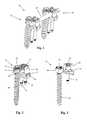
- FIG. 1is a perspective view of one example of a vertebral fixation system according to a first embodiment
- FIGS. 2 and 3are perspective and plan views, respectively, of an anchor assembly forming part of the vertebral fixation system of FIG. 1 ;
- FIG. 4is an exploded plan view of the anchor assembly of FIG. 2 ;
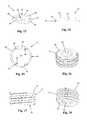
- FIGS. 5-8are perspective, top plan, side plan, and front plan views, respectively, of a fixation body forming part of the anchor assembly of FIG. 2 ;
- FIG. 9is a sectional view of the fixation body of FIG. 5 taken along line A-A of FIG. 6 ;
- FIGS. 10-12are perspective, side plan, and top plan views, respectively, of a rod-receiving member forming part of the anchor assembly of FIG. 2 ;
- FIGS. 13-15are perspective, side plan, and top plan views, respectively, of a washer member forming part of the anchor assembly of FIG. 2 ;
- FIGS. 16-18are perspective, side plan, and top plan views, respectively, of a rod lock member forming part of the anchor assembly of FIG. 2 ;
- FIGS. 19-21are perspective, side plan, and bottom plan views, respectively, of an anchor lock member forming part of the anchor assembly of FIG. 2 ;
- FIGS. 22-23are perspective and plan views, respectively, of a bone anchor forming part of the anchor assembly of FIG. 2 ;
- FIG. 24is a perspective view of an example sequential dilation system configured for use with the surgical fixation system of FIG. 1 ;
- FIG. 25is a perspective view of a distal end of the sequential dilation system of FIG. 24 ;
- FIG. 26is a perspective view of an initial dilator configured for use with the sequential dilation system of FIG. 24 ;
- FIG. 27is a perspective view of an alternate embodiment of a fixation dilator forming part of the sequential dilation system of FIG. 24 ;
- FIG. 28is a perspective view depicting of a pair of fixation assemblies being positioned on adjacent vertebrae during construction of the fixation assembly of FIG. 1 ;
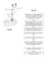
- FIG. 29is a flowchart denoting the steps of an example method for implanting an anchor assembly of FIG. 1 onto the lateral aspect of a vertebral body;
- FIG. 30is a flowchart denoting example steps of a method for performing a surgical procedure including a single level lateral fusion with fixation using the fixation system of FIG. 1 ;
- FIG. 31is a plan view of a single-level surgical fixation system of FIG. 1 fully implanted on a portion of a spine;
- FIG. 32is a flowchart denoting example steps of a method for performing a surgical procedure including a multilevel lateral fusion with fixation using the fixation system of FIG. 1 ;
- FIG. 33is a plan view of a multilevel surgical fixation system of FIG. 1 fully implanted on a portion of a spine;
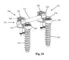
- FIG. 34is a perspective view of a second example of a vertebral fixation system according to a second embodiment.
- FIGS. 1-4illustrate an example of a vertebral fixation system 10 according to a first embodiment of the present invention.
- the vertebral fixation system 10includes at least a pair of anchor assemblies 12 connected by a spinal rod 14 .
- Each anchor assembly 12includes a fixation body 16 , a bone anchor 18 , a rod-receiving member 20 , a washer 22 , rod lock 24 , and an anchor lock 26 .
- the vertebral fixation system 10is configured to allow for independent implantation of the bone anchor 18 prior to implantation of the fixation body 16 (and the rest of the construct).
- the vertebral fixation system 10is semi-adjustable during implantation in that the rod-receiving members 20 have some freedom to translate and/or rotate relative to the fixation body 16 to accommodate insertion of the spinal rod 14 , which in many cases is not strictly straight due to the specific patient's spinal structure.
- the constructis locked in place by tightening the rod lock 24 , which in turn causes the rod-receiving member 20 to be locked in place relative to the fixation body 16 .
- the fixation body 16 of the instant examplehas a generally oblong footprint.
- the fixation body 16includes a first surface 28 and a second surface 30 opposite the first surface 28 , the second surface 30 including an upper shelf 31 and a lower shelf 33 .
- the first surface 28is configured to engage the vertebral body and thus has a generally concave curvature to better fit the generally convex contour of the lateral aspect of the vertebral body.
- the fixation body 16includes one or more projections 32 extending generally perpendicularly from the first surface 28 to provide purchase for the fixation body 16 within the vertebral body.
- the projections 32are provided as elongated cylindrical posts with a conical tip 34 that may be impacted into the vertebral body such that upon implantation of the fixation body 16 the first surface 28 rests flush against the lateral surface of the vertebral body.
- the projections 32may be provided with additional purchase features 36 to help prevent backout of the projections 32 once implanted.
- the purchase features 36are provided as a plurality of unidirectional tapered ridges positioned near a distal end of each projection 32 . The unidirectional tapered ridges allow for insertion of the projections 32 into bone and then subsequently resist the removal of the projections 32 from the bone.
- the projection 32may have a length ranging from approximately 15 mm to 40 mm and a diameter of approximately 3.5 mm.
- the relatively large dimension of the projection 32provide for increased torsional and compressive stability in bone.
- the projection design and anterior position on the fixation body 16reduce risk of nerve injury since the nerves (e.g. femoral nerve) are generally located more posteriorly along the spine.
- the projections 32may be provided in various alternative numbers and/or configurations from that shown.
- the projectionsmay be arranged along the perimeter of the first surface 28 .
- the number of projections 32may also vary from the two shown to include a single projection or many smaller projections without departing from the scope of the present disclosure.
- the upper shelf 31 of the fixation body 16includes an aperture 38 extending axially therethrough and is configured to receive the head 114 of the bone anchor 18 therein.
- the upper portion of the aperture 38includes a threaded region 40 that is configured to threadedly engage the anchor lock 26 .
- the lower portion of the aperture 38includes a conical taper 42 around the inner circumference of the aperture 38 .
- the conical taper 42interacts with the flexible extensions 108 of the anchor lock 26 to force the flexible extensions 108 inward about the head 114 of the bone anchor 18 . In this fashion, the anchor lock 26 forcibly engages the bone anchor 18 , thereby locking the fixation body 16 to the bone anchor 18 .
- the lower shelf 33 of upper surface 30is a generally planar surface and includes a passage configured to allow limited translation and/or rotation of the rod-receiving member 20 relative to the fixation body 16 .
- the passage of the example embodiment shownis a T-shaped recess 44 formed within the second surface 30 .
- the T-shaped recess 44is an elongated slot opening in the top surface 30 and an end of the fixation body 16 .
- the recess 44includes a generally planar bottom surface 46 and a pair of apertures 48 formed within the bottom surface 46 near the open end of the recess 44 .
- the apertures 48are configured to receive posts 50 ( FIG.
- the fixation body 16further includes a pair of lateral recesses 54 positioned on opposite side surfaces of the upper shelf 31 of fixation body 16 .
- the lateral recesses 54are configured to receive a portion (for example engagement flanges) of an insertion tool (not shown) to allow coupling with the inserter without enlarging the profile of the assembly within the operative space.
- FIGS. 10-12illustrate one example of a rod-receiving member 20 forming part of the vertebral fixation system 10 .
- the rod-receiving member 20includes a base 56 and a pair of upstanding arms 58 separated by a rod channel 60 .
- the base 56includes a protrusion 62 extending away from the base 56 and a cylindrical flange 64 positioned a the end of the protrusion 62 .
- the protrusion 62has a generally cylindrical shape and has a diameter that is less than the diameter of the cylindrical flange 64 . The result is that the protrusion 62 and flange 64 when taken together have a generally T-shaped cross section.
- the protrusion 62 and flange 64fit within the recess 44 of the fixation body 16 and are configured to allow multiple degrees of movement of the rod-receiving member 20 relative to the fixation body 16 . More specifically, the cylindrical shapes of both the protrusion 62 and flange 64 allow axial rotation of the rod-receiving member, and a generally planar bottom surface 66 of the flange 64 allows for smooth translation of the flange 64 (and thus the rod-receiving member 20 ) within the recess 44 .
- the upper surface 68 of the base 56is a concave, semi-cylindrical surface having a generally arcuate cross-section.
- the upper surface 68represents the distal end of the rod channel 60 and forms a cradle that receives the spinal rod 14 during implantation.
- the base 56further includes a pair of undercut recesses 70 formed within the base 56 just below each of the upstanding arms 58 .
- the undercut recesses 70are sized and configured to receive at least a portion of the washer 22 to provide a snug interaction between the washer 22 and the rod-receiving member 20 .
- the undercut recesses 70allow for capture of the washer during assembly and facilitates rotation of the washer with the rod-receiving member due to the non-circular shape of the rod-receiving member 20 .
- the upstanding arms 58are equipped with a rod lock guide and advancement feature 72 , such as by way of example, a helically wound flange feature disposed on the interior face of each arm 58 .
- the rod lock guide and advancement feature 72mates with a complementary guide and advancement feature 94 on the rod lock 24 ( FIG. 17 ).
- the rod lock 24engages the upstanding arms 58 via the complementary guide and advancement features 72 , 94 to press and lock the spinal rod 14 into the rod-receiving member 20 .
- the outer arcuate surfaces 74 of the upstanding armshave a convex curvature to minimize impaction of the surrounding tissue after implantation.
- the rod-receiving member 20also includes a pair of opposing outer planar surfaces 76 adjacent the rod channel 60 .
- Each upstanding arm 58further includes an attachment groove 78 , formed in the outer arcuate surface 74 near the proximal end of the upstanding arm 58 .
- the attachment grooves 78are dimensioned to receive engagement ridges or protrusions on the outer sleeve 202 of the guide assembly 200 to releasably lock the guide assembly 200 to the rod-receiving member 20 ( FIG. 28 ).
- the top of each upstanding arm 58further includes a recess 80 formed therein.
- the recesses 80are dimensioned to receive raised protrusions on the distal end of the inner arm members 204 of the guide assembly 200 . This interaction prevents rotation of the rod-receiving member 20 relative to the guide assembly 200 , such that the rod receiving member rotates with the guide member.
- the guide assembly 200may be similar to the type shown and described in commonly owned U.S. patent application Ser. No. 13/456,210, filed Apr. 25, 2012, the entire contents of which are hereby incorporated by reference into this disclosure as if set forth fully herein.
- the guide assembly 200includes an outer sleeve 202 and a pair of independent arms 204 that attach to the upstanding arms 58 of the rod-receiving member 20 .
- the guide assembly 200uses a slot formed between opposing inner arms 204 to guide the spinal rod 14 into the rod-receiving member 20 of the fixation body 16 and to be reduced or forced into the rod-receiving member 20 .
- the fixation bodies 16are inserted through the final dilators 164 with the guide assemblies 200 attached. Thereafter the final dilators 164 are removed leaving the guide assemblies connected to the rod-receiving member and extending out of the incision.
- the guide assemblies 200are utilized to direct rod placement within the rod-receiving members of each anchor assembly 12 of the fixation construct and to facilitate insertion of rod locks 24 .
- the washer 22includes a solid ring 82 with a through passage 84 configured to receive the undercut recesses 70 of the rod-receiving member 20 .
- the washer 22has an outer surface 86 having a generally circular cross-section.
- the washer 22further includes a pair of raised protrusions 88 positioned on opposing sides of the through passage 84 .
- the raised protrusions 88each have a generally planar interior surface 90 .
- the remaining interior surfaces of the washer 22have an arcuate shape.
- the peripheral shape of the through passage 84is complimentary to the peripheral shape of the rod-receiving member 20 , allowing for a snug mating of the rod-receiving member 20 and the washer 22 .
- the raised protrusions 88include a pair of concave recesses 92 configured to seat the spinal rod 14 therein.
- the washer 22sits between the rod-receiving member 20 and the fixation body 16 . When the anchor assembly 12 is in an unlocked state, the washer 22 is able move with the rod-receiving member 20 (but does not move relative to the rod-receiving member 20 ), allowing multiple degrees of movement (e.g.
- the spinal rod 22sits in the concave recesses 92 on either side of the washer 22 .
- the recesses 92are concave in the embodiment shown and described herein, but could be any shape (e.g. V-shaped) that allows of sufficient seating of the spinal rod 14 .
- the washer 22is forced into the fixation body 16 which creates a friction lock between the washer 22 and the fixation body 16 .
- This locking prior to rod lockingmay be temporary or permanent and may be accomplished, for example, with a tool that engages around or through the guide to interact with the washer and/or rod-receiving member, or through a feature built into the guide itself that interacts with the washer and/or rod-receiving member.
- the tool or featuremay include, among others, a press, swedge, or crimp. Locking the rod-receiving tulip prior to rod insertion (or after rod insertion but prior to rod locking) allows the surgeon to apply force to the vertebra through the guide assembly which can be utilized to accomplish derotation maneuvers, compression, distraction, or other manipulations to change the alignment of the vertebrae.
- the rod lock 24is a setscrew-type locking device that has a generally cylindrical shape and is received within the rod channel 60 of the rod-receiving member 20 .
- the rod lock 24is equipped with a guide and advancement feature 94 , such as by way of example, a helically wound flange feature disposed around the outer surface of the rod lock 24 .
- the guide and advancement feature 94mates with the complementary rod lock guide and advancement feature 72 on the rod-receiving member 20 , described above.
- the rod lock 24further includes a rod-engaging distal surface 96 adapted to contact the spinal rod 14 during use.
- the distal surface 96is shown as being generally planar, however the distal surface 96 may have other configurations (e.g. convex or concave) without departing from the scope of this disclosure.
- the rod lock 24also includes a central aperture 98 configured for mating with an insertion and drive tool (not shown) to apply sufficient torque to lock the anchor assembly 12 together.
- the anchor lock 26is used to lock the bone anchor 18 to the fixation body 16 .
- the anchor lock 26is generally cylindrical in shape and includes a first region 100 configured to engage the fixation body 16 and a second region 102 configured to engage the head 114 of the bone anchor 18 . While shown herein as a single piece, anchor lock 26 may be have a multi-piece configuration in which the first region 100 and second region 102 are separate pieces (such that the second region 102 is rotationally uncoupled from first region 100 ).
- the first region 100includes a helical thread 104 configured to threadedly engage the threaded region 40 of the aperture 38 of the fixation body 16 .
- the threaded engagementallows the anchor lock 26 to be rotationally advanced into the aperture 38 to lock the bone anchor 18 to the fixation body 16 .
- the first region 100further includes a central aperture 106 configured to receive an insertion and driver tool (not shown).
- the second region 102includes a series of flexible extensions 108 distributed radially about the circumference of the anchor lock 26 . As will be explained below, the flexible extensions 108 are capable of being deflected inward by the conical taper 42 of the aperture 38 as the anchor lock 26 is advanced into the aperture 38 .
- an anchor lock 26may include a rotation clamp, split ring and set screw, or two-piece clamp and set screw.
- the internal features of the anchor lock showninclude a spherical surface to hold anchor and flats to allow the anchor to go into anchor lock with ease during insertion.
- the anchor lock 26may be provided with a mechanism to prevent rotation of the second region 102 during insertion.
- at least one of the flexible extensions 108may include a recess 110 configured to mate with a ridge 112 formed within the aperture 38 ( FIG. 6 ).
- the bone anchor 18includes a head portion 114 , a neck portion 116 , and a threaded shaft 118 .
- the head portion 114includes an engagement recess 120 formed therein that is configured to engage with a suitable driver instrument (not shown).
- the neck portion 116is a generally smooth (e.g. non-threaded) surface extending circumferentially around the bone anchor 18 .
- the diameter of the neck portion 116is smaller than the largest diameter of the head portion 114 , which creates a space to receive the deflected distal ends of the flexible extensions 108 of the anchor lock 26 during use.
- the threaded shaft 118extends distally from the neck region 116 and may be any length suitable to achieve purchase in the bone.
- the distal end 122 of the bone anchor 18may include a sharp and retractable element (not shown) that can be maintained within the distal end 122 and exposed only when starting the bone anchor 18 into bone.
- the sharp endallows the bone anchor 18 to be used without first forming a pilot hole. Retracting the sharp end into the shank allows the bone anchor 122 to be positioned bicortically, that is the distal end 122 can rest right at the edge of the vertebral body without worrying that that the sharp tip may extend outside the periphery of the vertebral body and contact sensitive tissue (e.g. segmental vessels).
- the bone anchor 18may be cannulated to allow for the use of a K-wire (for example) to aid in placement of the bone anchor 18 within the target site.
- FIGS. 24-27illustrate a sequential dilation system 130 configured for use to introduce components of the surgical fixation system 10 to the surgical target site.
- the initial dilator 132comprises an elongated cannulated body 134 .
- the distal end 136is tapered to facilitate safe passage through tissue lying above the spine.
- the distal endmay also include an electrode 138 to facilitate passage through tissue nerve occupied tissue.
- the electrode 138is configured for connection with a neuromonitoring system, for example of the type shown and described in U.S. Pat. No. 8,255,045, issued Aug. 28, 2012, for detecting the presence and direction of nerves near the distal end of the initial dilator.
- a proximal connector region 140is configured to receive an electrical connector (for example, not shown) to connect the dilator to the neuromonitoring system.
- the main body of the initial dilator 134is insulated (except for connector region 140 and electrode 138 ) to prevent current shunting.
- the initial dilator 132includes an integrated needle 144 that may be deployed into the bone to hold the position of the initial dilator 132 in the desired location against the spine.
- a spring(not shown) maintains the needle in a first position in which a sharp distal end of the needle is contained within the main body cannulation 142 in order to protect the tissue during dilator passage.
- the needle 144is depressed, advancing the distal end beyond the main body such that it engages into the vertebral body. Friction between the needle and the vertebral body prevents the needle 144 from returning to the original biased position.
- the additional dilatorsinclude a fixation dilator 146 , a transition dilator 174 , and a final dilator 164 .
- the fixation dilator 146has an elongated generally cylindrical body 148 having a main lumen 150 extending therethrough for passage over the initial dilator.
- the diameter of the main lumen 150is also such that the bone anchor 18 (and a tap, if utilized) can pass therethrough for implantation into the vertebra.
- Fixation dilator 146also includes a radiopaque marker 154 (e.g. a metal ring situated in a groove or multiple (e.g. 4 ) internal metal pins) near the distal end 156 of the dilator.
- the radiopaque marker 154allows the user to intraoperatively view (e.g.
- the distal end of the fixation dilatormay also include an electrode 158 configured for connection with a neuromonitoring system.
- a proximal connector region 160 near proximal end 162is configured to receive an electrical connector of the neuromonitoring system, the dilator 146 being insulated everywhere but the proximal connector 160 and the electrode 158 in order to prevent current shunting.
- the electrode 158is preferably positioned such that it corresponds to the position of the fixation lumens 152 .
- FIG. 27illustrates an alternate embodiment of fixation dilator 146 which includes only a single fixation lumen 152 and the electrode 158 is positioned directly below the fixation lumen 152 .
- the final dilator 164includes a main body 166 with a lumen 168 extending from proximal end 170 to a distal end 172 .
- the lumen 168dimensioned such that the final dilator can advance to the spine over the transitional dilator 174 and such that the fixation body 16 can pass therethrough for implantation to the vertebra.
- the footprint of the final dilator 164is shaped to correspond to the fixation body 16 , and thus, according to the example embodiment shown, is generally oblong in cross-sectional shape.
- the transition dilator 174also includes a main body 176 and a lumen 178 extending therethrough from a proximal end 180 to a distal end 182 .
- the transition dilatorserves as a transition from the generally cylindrical shape of the initial 132 and fixation 146 dilators to the generally oblong shape of the final dilator 164 .
- the lumen 178then is generally cylindrical (with recesses to accommodate the fixation lumens) and dimensioned to pass over the fixation dilator 146 .
- the main body 176includes an asymmetric taper 184 that increases from a dimension just larger than the fixation dilator 146 at the very distal end 182 to a dimension just smaller than the lumen 168 of the final dilator 164 .
- the initial dilator 132is advanced through a lateral incision to the desired position on the lateral aspect of the vertebral body. If the path of the dilator 132 will traverse nerve occupied tissue, for example, when traversing the psoas muscle to access lower levels of the lumbar spine, a neurophysiology monitoring system may be connected to the initial dilator 132 for nerve detection during advancement. When the dilator is correctly positioned on the vertebral body, the needle 144 is depressed to anchor the needle in the vertebral body and dock the initial dilator in place.
- the fixation dilator 146is advanced over the initial dilator, again, nerve detection may be employed if nerve occupied tissue (e.g. psoas is traversed.
- a k-wire(s)can then be advanced through the fixation lumen(s) and anchored into the vertebral body to dock the fixation dilator.
- the initial dilatoris removed and the bone anchor is advanced through the lumen 150 and anchored to the vertebral body.
- the transition dilator 174is then advanced to the vertebra over the fixation dilator followed by the final dilator 164 .
- the transition dilator 174 and fixation dilator 146are removed.
- the fixation body 16is then advanced through the lumen 168 of the final dilator until the Transition and fixation dilators are removed and the fixation body is advanced through the final dilator and locked to the bone anchor head 114 is fully received in the aperture 38 of the fixation body and anterior protrusions 32 are anchored in the vertebral body.
- the anchoris then locked to the fixation body by engaging the threads of the anchor lock 26 with the threads 40 in the aperture 28 to advance the lock until the flexible extensions 108 are deflected by the conical taper 42 and capture the head 114 of the bone anchor 18 .
- the final dilatoris removed leaving the guide assembly attached to the rod-receiving member and extending out of the incision.
- the vertebral fixation system 10is generally utilized to augment a corrective procedure performed on the spine, such as, a spinal fusion.
- the spinal fixation system 10may be used to provide fixation after lateral interbody fusion performed.
- the spinal fixation system 10could also be used, for example, to provide fixation after a lateral corpectomy is performed.
- the lateral interbody fusion procedureis entails creating a lateral access corridor to the disc, performing a discectomy, and implanting a fusion implant into disc space created by the discectomy.
- An example technique for accessing the lateral spine to perform a fusionis described in U.S. Pat. No. 7,905,840 entitled “Surgical Access System and Related Methods,” issued Mar. 15, 2011.
- the fixation system 10When utilizing the spinal fixation system 10 , the fusion (or other corrective procedure, e.g. corpectomy) is completed on each level and then the fixation system 10 is applied utilizing the original access incision(s) where possible to limit the amount of incising required to complete the entire surgical procedure (e.g. fusion and fixation).
- a lateral access corridoris created through a first incision and fusion is procedure is complete, as is described by way of example in the '840 patent. If the disc is at a level where the path to the disc will traverse nerve occupied tissue, for example, the psoas muscle, the creation of the operative corridor is preferably completed with the aid of neurophysiology monitoring for nerve detection. After the fusion work on the disc is complete, the retractor can be moved relative to the spine (i.e. without removing from the incision) such that the corridor through the retractor rests over the first vertebra.
- the first fixation assembly 12can then be implanted through the operative corridor.
- the first fixation assemblyis implanted using the sequential dilation system 130 . If the operative corridor traverses the psoas, rather than moving the retractor, the retractor may be removed and the initial dilator 132 may be advanced through the first incision (which can then be moved to one side and positioned over the first vertebral body) and establish a new path (aided by neurophysiology monitoring) through the psoas for subsequent dilation and anchor assembly implantation (as previously described). The dilation system 30 is removed leaving the guide assembly 200 extending from the first incision.
- FIG. 31depicts the completed single level spinal construct using the spinal fixation system 10 .
- the retractoris moved relative to the spine without withdrawing from the incision and positioned over the L1/L2 disc space and the fusion procedure is completed at that level.
- a second lateral incisionmay be made over the T12 body.
- the incisionis moved over the T12/L1 disc space and a lateral access corridor is created and fusion procedure completed. If the access path to one or more of the disc spaces is to traverse the psoas, rather than simply moving the retractor, it is preferable that the retractor be withdrawn and a new path through the psoas be created (utilizing the same incision however) with the aid of neurophysiology monitoring and sequential dilation.
- the fixation system 10can be constructed. To do so, the dilation system 130 is utilized through the first incision to implant a first anchor assembly 12 on the L3 vertebral body with guide assembly 200 attached and extending out of the first incision. The first incision is then stretched over to the L2 vertebral body and a dilator system 130 is used to implant a second anchor assembly 12 on the L2 body with a guide assembly 200 attached and also extending out of the first incision. A third anchor assembly 12 is implanted on the L1 vertebral body using a dilator system 130 . Depending on the patients skin, fascia, and anatomy, the surgeon can target the L1 body either the first or the second incision.
- FIG. 33depicts the completed multilevel spinal construct using the spinal fixation system 10 .
- FIG. 34illustrates an example of a surgical fixation system 210 according to an alternative embodiment.
- the vertebral fixation system 210includes at least a pair of anchor assemblies 212 connected by a spinal rod 214 .
- Each anchor assembly 212includes a fixation body 216 , a bone anchor 218 , a rod-receiving member 220 , rod lock 224 , and an anchor lock 226 .
- the fixation system 210differs from the fixation system 10 in one major aspect.
Landscapes
- Health & Medical Sciences (AREA)
- Orthopedic Medicine & Surgery (AREA)
- Life Sciences & Earth Sciences (AREA)
- Surgery (AREA)
- Neurology (AREA)
- Heart & Thoracic Surgery (AREA)
- General Health & Medical Sciences (AREA)
- Biomedical Technology (AREA)
- Nuclear Medicine, Radiotherapy & Molecular Imaging (AREA)
- Medical Informatics (AREA)
- Molecular Biology (AREA)
- Animal Behavior & Ethology (AREA)
- Engineering & Computer Science (AREA)
- Public Health (AREA)
- Veterinary Medicine (AREA)
- Dentistry (AREA)
- Oral & Maxillofacial Surgery (AREA)
- Surgical Instruments (AREA)
- Prostheses (AREA)
Abstract
Description
Claims (19)
Priority Applications (1)
| Application Number | Priority Date | Filing Date | Title |
|---|---|---|---|
| US14/748,048US9579131B1 (en) | 2012-03-08 | 2015-06-23 | Systems and methods for performing spine surgery |
Applications Claiming Priority (5)
| Application Number | Priority Date | Filing Date | Title |
|---|---|---|---|
| US13/415,769US8992579B1 (en) | 2011-03-08 | 2012-03-08 | Lateral fixation constructs and related methods |
| US13/456,210US9198698B1 (en) | 2011-02-10 | 2012-04-25 | Minimally invasive spinal fixation system and related methods |
| US201261679018P | 2012-08-02 | 2012-08-02 | |
| US13/831,696US9060815B1 (en) | 2012-03-08 | 2013-03-15 | Systems and methods for performing spine surgery |
| US14/748,048US9579131B1 (en) | 2012-03-08 | 2015-06-23 | Systems and methods for performing spine surgery |
Related Parent Applications (1)
| Application Number | Title | Priority Date | Filing Date |
|---|---|---|---|
| US13/831,696ContinuationUS9060815B1 (en) | 2012-03-08 | 2013-03-15 | Systems and methods for performing spine surgery |
Publications (1)
| Publication Number | Publication Date |
|---|---|
| US9579131B1true US9579131B1 (en) | 2017-02-28 |
Family
ID=53396983
Family Applications (2)
| Application Number | Title | Priority Date | Filing Date |
|---|---|---|---|
| US13/831,696ActiveUS9060815B1 (en) | 2012-03-08 | 2013-03-15 | Systems and methods for performing spine surgery |
| US14/748,048ActiveUS9579131B1 (en) | 2012-03-08 | 2015-06-23 | Systems and methods for performing spine surgery |
Family Applications Before (1)
| Application Number | Title | Priority Date | Filing Date |
|---|---|---|---|
| US13/831,696ActiveUS9060815B1 (en) | 2012-03-08 | 2013-03-15 | Systems and methods for performing spine surgery |
Country Status (1)
| Country | Link |
|---|---|
| US (2) | US9060815B1 (en) |
Cited By (10)
| Publication number | Priority date | Publication date | Assignee | Title |
|---|---|---|---|---|
| US20160038195A1 (en)* | 2014-08-08 | 2016-02-11 | K2M, Inc. | Retraction devices, systems, and methods for minimally invasive spinal surgery |
| US10624623B1 (en) | 2019-02-12 | 2020-04-21 | Edward Rustamzadeh | Lateral retractor system for minimizing muscle damage in spinal surgery |
| US10631842B1 (en)* | 2019-02-12 | 2020-04-28 | Edward Rustamzadeh | Lateral retraction system for minimizing muscle damage in spinal surgery |
| US10799230B2 (en) | 2019-02-12 | 2020-10-13 | Edward Rustamzadeh | Lateral retractor system for minimizing muscle damage in spinal surgery |
| US10925593B2 (en) | 2019-02-12 | 2021-02-23 | Edward Rustamzadeh | Lateral retractor system for minimizing muscle damage in spinal surgery |
| US10925592B2 (en)* | 2016-01-19 | 2021-02-23 | K2M, Inc. | Tissue dilation system and methods of use |
| US11246582B2 (en) | 2019-02-12 | 2022-02-15 | Edward Rustamzadeh | Dual-motion rotation and retraction system for minimizing muscle damage in spinal surgery |
| US11744569B2 (en) | 2019-02-12 | 2023-09-05 | Edward Rustamzadeh | Lateral retractor system for minimizing muscle damage in spinal surgery |
| USD1002842S1 (en) | 2021-06-29 | 2023-10-24 | Edward Rustamzadeh | Combination surgical spinal dilator and retractor system |
| US12082849B2 (en) | 2019-04-12 | 2024-09-10 | Orthopediatrics Corp. | Dual tether support of vertebra |
Families Citing this family (26)
| Publication number | Priority date | Publication date | Assignee | Title |
|---|---|---|---|---|
| US9877747B2 (en)* | 2009-09-02 | 2018-01-30 | Globus Medical, Inc. | Spine stabilization system |
| US9333090B2 (en) | 2010-01-13 | 2016-05-10 | Jcbd, Llc | Systems for and methods of fusing a sacroiliac joint |
| US9421109B2 (en) | 2010-01-13 | 2016-08-23 | Jcbd, Llc | Systems and methods of fusing a sacroiliac joint |
| WO2014015309A1 (en) | 2012-07-20 | 2014-01-23 | Jcbd, Llc | Orthopedic anchoring system and methods |
| US9717539B2 (en) | 2013-07-30 | 2017-08-01 | Jcbd, Llc | Implants, systems, and methods for fusing a sacroiliac joint |
| WO2014146018A1 (en) | 2013-03-15 | 2014-09-18 | Jcbd, Llc | Systems and methods for fusing a sacroiliac joint and anchoring an orthopedic appliance |
| US9826986B2 (en) | 2013-07-30 | 2017-11-28 | Jcbd, Llc | Systems for and methods of preparing a sacroiliac joint for fusion |
| US10245087B2 (en) | 2013-03-15 | 2019-04-02 | Jcbd, Llc | Systems and methods for fusing a sacroiliac joint and anchoring an orthopedic appliance |
| US9700356B2 (en) | 2013-07-30 | 2017-07-11 | Jcbd, Llc | Systems for and methods of fusing a sacroiliac joint |
| US9801546B2 (en) | 2014-05-27 | 2017-10-31 | Jcbd, Llc | Systems for and methods of diagnosing and treating a sacroiliac joint disorder |
| US9737340B1 (en)* | 2014-09-16 | 2017-08-22 | Nuvasive, Inc. | Adjustable iliac connector |
| US9743921B2 (en)* | 2014-09-25 | 2017-08-29 | Warsaw Orthopedic, Inc. | Spinal implant system and method |
| DE102014117175A1 (en)* | 2014-11-24 | 2016-05-25 | Aesculap Ag | Pedicle screw system and spine stabilization system |
| US9962192B2 (en) | 2016-03-17 | 2018-05-08 | Medos International Sarl | Multipoint fixation implants |
| US10517647B2 (en) | 2016-05-18 | 2019-12-31 | Medos International Sarl | Implant connectors and related methods |
| US10321939B2 (en) | 2016-05-18 | 2019-06-18 | Medos International Sarl | Implant connectors and related methods |
| US10398476B2 (en) | 2016-12-13 | 2019-09-03 | Medos International Sàrl | Implant adapters and related methods |
| US10492835B2 (en) | 2016-12-19 | 2019-12-03 | Medos International Sàrl | Offset rods, offset rod connectors, and related methods |
| US10238432B2 (en)* | 2017-02-10 | 2019-03-26 | Medos International Sàrl | Tandem rod connectors and related methods |
| US10966761B2 (en) | 2017-03-28 | 2021-04-06 | Medos International Sarl | Articulating implant connectors and related methods |
| US10561454B2 (en) | 2017-03-28 | 2020-02-18 | Medos International Sarl | Articulating implant connectors and related methods |
| US10603055B2 (en) | 2017-09-15 | 2020-03-31 | Jcbd, Llc | Systems for and methods of preparing and fusing a sacroiliac joint |
| US11076890B2 (en) | 2017-12-01 | 2021-08-03 | Medos International Sàrl | Rod-to-rod connectors having robust rod closure mechanisms and related methods |
| US10898232B2 (en) | 2018-03-20 | 2021-01-26 | Medos International Sàrl | Multipoint fixation implants and related methods |
| US11426210B2 (en) | 2019-09-25 | 2022-08-30 | Medos International Sàrl | Multipoint angled fixation implants for multiple screws and related methods |
| EP4103083B1 (en)* | 2020-02-14 | 2024-10-23 | Medos International Sàrl | Integrated multipoint fixation screw |
Citations (375)
| Publication number | Priority date | Publication date | Assignee | Title |
|---|---|---|---|---|
| US208227A (en) | 1878-09-24 | Improvement in vaginal speculums | ||
| US972983A (en) | 1909-05-17 | 1910-10-18 | Lester R Lantz | Dilator. |
| US1328624A (en) | 1917-08-13 | 1920-01-20 | Frank B Graham | Dilator |
| US3196876A (en) | 1961-05-10 | 1965-07-27 | Maurice M Miller | Dilator |
| US3741205A (en) | 1971-06-14 | 1973-06-26 | K Markolf | Bone fixation plate |
| US3788318A (en) | 1972-06-12 | 1974-01-29 | S Kim | Expandable cannular, especially for medical purposes |
| US3997138A (en) | 1974-06-18 | 1976-12-14 | Henry Vernon Crock | Securing devices and structures |
| US4047524A (en) | 1975-04-28 | 1977-09-13 | Downs Surgical Limited | Surgical implant spinal staple |
| US4289123A (en) | 1980-03-31 | 1981-09-15 | Dunn Harold K | Orthopedic appliance |
| US4545374A (en) | 1982-09-03 | 1985-10-08 | Jacobson Robert E | Method and instruments for performing a percutaneous lumbar diskectomy |
| US4573448A (en) | 1983-10-05 | 1986-03-04 | Pilling Co. | Method for decompressing herniated intervertebral discs |
| US4611581A (en) | 1983-12-16 | 1986-09-16 | Acromed Corporation | Apparatus for straightening spinal columns |
| US4620533A (en) | 1985-09-16 | 1986-11-04 | Pfizer Hospital Products Group Inc. | External bone fixation apparatus |
| US4648388A (en) | 1985-11-01 | 1987-03-10 | Acromed Corporation | Apparatus and method for maintaining vertebrae in a desired relationship |
| US4653481A (en) | 1985-07-24 | 1987-03-31 | Howland Robert S | Advanced spine fixation system and method |
| US4773402A (en) | 1985-09-13 | 1988-09-27 | Isola Implants, Inc. | Dorsal transacral surgical implant |
| US5007902A (en) | 1988-03-09 | 1991-04-16 | B. Braun Melsungen Ag | Catheter set for plexus anesthesia |
| US5024213A (en) | 1989-02-08 | 1991-06-18 | Acromed Corporation | Connector for a corrective device |
| US5074864A (en) | 1988-12-21 | 1991-12-24 | Zimmer, Inc. | Clamp assembly for use in a spinal system |
| US5085660A (en) | 1990-11-19 | 1992-02-04 | Lin Kwan C | Innovative locking plate system |
| US5108395A (en) | 1989-09-18 | 1992-04-28 | Societe De Fabrication De Materiel Orthopedique - Sofamor | Implant for anterior dorsolumbar spinal osteosynthesis, intended for the correction of kyphoses |
| US5129899A (en) | 1991-03-27 | 1992-07-14 | Smith & Nephew Richards Inc. | Bone fixation apparatus |
| US5137509A (en) | 1991-04-17 | 1992-08-11 | Dexide, Inc. | Surgical insufflation instrument |
| US5147360A (en) | 1990-02-19 | 1992-09-15 | Societe De Fabrication De Materiel Orthopedique | Osteosynthesis device for the correction of spinal curvatures |
| US5147361A (en) | 1989-11-29 | 1992-09-15 | Asahi Kogaku Kogyo Kabushiki Kaisha | Vertebral connecting plate |
| US5152303A (en) | 1991-06-18 | 1992-10-06 | Carl Allen | Anterolateral spinal fixation system and related insertion process |
| US5158543A (en) | 1990-10-30 | 1992-10-27 | Lazarus Harrison M | Laparoscopic surgical system and method |
| US5171279A (en) | 1992-03-17 | 1992-12-15 | Danek Medical | Method for subcutaneous suprafascial pedicular internal fixation |
| US5195541A (en) | 1991-10-18 | 1993-03-23 | Obenchain Theodore G | Method of performing laparoscopic lumbar discectomy |
| US5242427A (en) | 1990-11-06 | 1993-09-07 | Ethicon, Inc. | Surgical instrument forming a trocar |
| US5261909A (en) | 1992-02-18 | 1993-11-16 | Danek Medical, Inc. | Variable angle screw for spinal implant system |
| WO1994000062A1 (en) | 1992-06-19 | 1994-01-06 | Pierre Roussouly | Spinal therapy apparatus |
| US5295994A (en) | 1991-11-15 | 1994-03-22 | Bonutti Peter M | Active cannulas |
| US5306275A (en) | 1992-12-31 | 1994-04-26 | Bryan Donald W | Lumbar spine fixation apparatus and method |
| CN2162921Y (en) | 1992-12-30 | 1994-04-27 | 淄博市中心医院 | Trocar for excision of marrow nucleus from intervertebral disc through skin puncture |
| US5312417A (en) | 1992-07-29 | 1994-05-17 | Wilk Peter J | Laparoscopic cannula assembly and associated method |
| US5324290A (en) | 1992-09-24 | 1994-06-28 | Danek Medical, Inc. | Anterior thoracolumbar plate |
| US5330473A (en) | 1993-03-04 | 1994-07-19 | Advanced Spine Fixation Systems, Inc. | Branch connector for spinal fixation systems |
| US5331975A (en) | 1990-03-02 | 1994-07-26 | Bonutti Peter M | Fluid operated retractors |
| US5342384A (en) | 1992-08-13 | 1994-08-30 | Brigham & Women's Hospital | Surgical dilator |
| FR2704136A1 (en) | 1993-04-21 | 1994-10-28 | Fournitures Hospitalieres | Screw, in particular for surgical operation |
| US5364399A (en) | 1993-02-05 | 1994-11-15 | Danek Medical, Inc. | Anterior cervical plating system |
| US5368594A (en) | 1991-09-30 | 1994-11-29 | Fixano S.A. | Vertebral osteosynthesis device |
| US5378241A (en) | 1992-06-24 | 1995-01-03 | Haindl; Hans | Anesthesia instrument |
| US5380324A (en) | 1992-05-18 | 1995-01-10 | Pina Vertriebs Ag | Implantable device for straightening and fixing vertebrae |
| US5380323A (en) | 1993-06-16 | 1995-01-10 | Advanced Spine Fixation Systems, Inc. | Clamps for spinal fixation systems |
| US5380325A (en) | 1992-11-06 | 1995-01-10 | Biomat | Osteosynthesis device for spinal consolidation |
| EP0637437A1 (en) | 1993-05-14 | 1995-02-08 | SMITH & NEPHEW RICHARDS, INC. | Composite spinal apparatus |
| US5395317A (en) | 1991-10-30 | 1995-03-07 | Smith & Nephew Dyonics, Inc. | Unilateral biportal percutaneous surgical procedure |
| US5401247A (en) | 1990-12-18 | 1995-03-28 | Yoon; Inbae | Safety penetrating instrument |
| US5445617A (en) | 1991-11-27 | 1995-08-29 | Yoon; Inbae | Automatic retractable safety penetrating instrument for portal sleeve introduction and method of use |
| US5476467A (en) | 1994-06-14 | 1995-12-19 | Benoist; Louis A. | Surgical hammer for driving K-wires |
| DE4429744A1 (en) | 1994-08-22 | 1996-02-29 | Martin Storz | Safety trocar for use by surgeons |
| US5509893A (en) | 1991-06-06 | 1996-04-23 | Meditech International Pty Ltd. | Speculum |
| US5514153A (en) | 1990-03-02 | 1996-05-07 | General Surgical Innovations, Inc. | Method of dissecting tissue layers |
| US5520690A (en) | 1995-04-13 | 1996-05-28 | Errico; Joseph P. | Anterior spinal polyaxial locking screw plate assembly |
| US5549608A (en) | 1995-07-13 | 1996-08-27 | Fastenetix, L.L.C. | Advanced polyaxial locking screw and coupling element device for use with rod fixation apparatus |
| WO1996032882A1 (en) | 1995-04-20 | 1996-10-24 | Heartport, Inc. | Method and apparatus for thoracoscopic intracardiac procedures |
| US5569289A (en) | 1993-06-24 | 1996-10-29 | Yoon; Inbae | Safety penetrating instrument with penetrating member and cannula moving during penetration and triggered safety member protusion |
| US5573511A (en) | 1991-11-27 | 1996-11-12 | Yoon; Inbae | Retractable safety penetrating instrument with safety probe |
| US5599279A (en) | 1994-03-16 | 1997-02-04 | Gus J. Slotman | Surgical instruments and method useful for endoscopic spinal procedures |
| US5603714A (en) | 1993-12-15 | 1997-02-18 | Mizuho Ika Kogyo Kabushiki Kaisha | Instrument for anterior correction of scoliosis or the like |
| US5613968A (en) | 1995-05-01 | 1997-03-25 | Lin; Chih-I | Universal pad fixation device for orthopedic surgery |
| US5620443A (en) | 1995-01-25 | 1997-04-15 | Danek Medical, Inc. | Anterior screw-rod connector |
| US5662653A (en) | 1996-02-22 | 1997-09-02 | Pioneer Laboratories, Inc. | Surgical rod-to-bone attachment |
| US5662652A (en) | 1994-04-28 | 1997-09-02 | Schafer Micomed Gmbh | Bone surgery holding apparatus |
| US5665072A (en) | 1991-11-27 | 1997-09-09 | Yoon; Inbae | Safety needle instrument with movable cannula and needle |
| US5667509A (en) | 1995-03-02 | 1997-09-16 | Westin; Craig D. | Retractable shield apparatus and method for a bone drill |
| US5672176A (en) | 1995-03-15 | 1997-09-30 | Biedermann; Lutz | Anchoring member |
| US5681312A (en) | 1996-05-31 | 1997-10-28 | Acromed Corporation | Spine construct with band clamp |
| US5690629A (en) | 1996-04-24 | 1997-11-25 | Acromed Corporation | Apparatus for maintaining vertebrae of a spinal column in a desired spatial relationship |
| US5697947A (en) | 1993-09-07 | 1997-12-16 | Invamed, Inc. | Trocar obturator including a removable knife |
| US5702395A (en) | 1992-11-10 | 1997-12-30 | Sofamor S.N.C. | Spine osteosynthesis instrumentation for an anterior approach |
| US5704936A (en) | 1992-04-10 | 1998-01-06 | Eurosurgical | Spinal osteosynthesis device |
| US5707359A (en) | 1995-11-14 | 1998-01-13 | Bufalini; Bruno | Expanding trocar assembly |
| US5713898A (en) | 1993-05-18 | 1998-02-03 | Schafer Micomed Gmbh | Orthopedic surgical holding device |
| US5713900A (en) | 1996-05-31 | 1998-02-03 | Acromed Corporation | Apparatus for retaining bone portions in a desired spatial relationship |
| US5728127A (en) | 1995-06-27 | 1998-03-17 | Acro Med Corporation | Apparatus for maintaining vertebrae of a spinal column in a desired spatial relationship |
| US5762629A (en) | 1991-10-30 | 1998-06-09 | Smith & Nephew, Inc. | Oval cannula assembly and method of use |
| US5766254A (en) | 1992-08-11 | 1998-06-16 | Gelbard; Steven D. | Spinal stabilization implant system |
| US5772678A (en) | 1995-10-20 | 1998-06-30 | Inlet Medical, Inc. | Retractable disposable tip reusable trocar obturator |
| US5792044A (en) | 1996-03-22 | 1998-08-11 | Danek Medical, Inc. | Devices and methods for percutaneous surgery |
| US5800435A (en) | 1996-10-09 | 1998-09-01 | Techsys, Llc | Modular spinal plate for use with modular polyaxial locking pedicle screws |
| US5814073A (en) | 1996-12-13 | 1998-09-29 | Bonutti; Peter M. | Method and apparatus for positioning a suture anchor |
| US5817071A (en) | 1997-01-09 | 1998-10-06 | Medtronic, Inc. | Oval-shaped cardiac cannula |
| US5842478A (en) | 1991-12-03 | 1998-12-01 | Boston Scientific Technology, Inc. | Method of securing a bone anchor |
| EP0888754A1 (en) | 1997-07-03 | 1999-01-07 | Acromed Corporation | Osteosynthetic Fastener |
| US5882350A (en) | 1995-04-13 | 1999-03-16 | Fastenetix, Llc | Polyaxial pedicle screw having a threaded and tapered compression locking mechanism |
| US5888196A (en) | 1990-03-02 | 1999-03-30 | General Surgical Innovations, Inc. | Mechanically expandable arthroscopic retractors |
| US5899904A (en) | 1998-10-19 | 1999-05-04 | Third Milennium Engineering, Llc | Compression locking vertebral body screw, staple, and rod assembly |
| US5899902A (en) | 1997-07-03 | 1999-05-04 | Depuy Motech Acromed Corporation | Fastener |
| US5899905A (en) | 1998-10-19 | 1999-05-04 | Third Millennium Engineering Llc | Expansion locking vertebral body screw, staple, and rod assembly |
| US5925047A (en) | 1998-10-19 | 1999-07-20 | Third Millennium Engineering, Llc | Coupled rod, anterior vertebral body screw, and staple assembly |
| US5928233A (en) | 1995-12-22 | 1999-07-27 | Ohio Medical Instrument Co., Inc. | Spinal fixation device with laterally attachable connectors |
| US5928243A (en) | 1997-07-16 | 1999-07-27 | Spinal Concepts, Inc. | Pedicle probe and depth gage |
| US5947969A (en) | 1998-10-19 | 1999-09-07 | Third Millennium Engineering, Llc | Rotatable locking vertebral body screw, staple and rod assembly |
| US5976135A (en) | 1997-12-18 | 1999-11-02 | Sdgi Holdings, Inc. | Lateral connector assembly |
| US5976146A (en) | 1997-07-11 | 1999-11-02 | Olympus Optical Co., Ltd. | Surgical operation system and method of securing working space for surgical operation in body |
| US6004322A (en) | 1994-10-25 | 1999-12-21 | Sdgi Holdings, Inc. | Modular pedicle screw system |
| US6033420A (en) | 1998-09-02 | 2000-03-07 | Embol-X, Inc. | Trocar introducer system and methods of use |
| US6063090A (en) | 1996-12-12 | 2000-05-16 | Synthes (U.S.A.) | Device for connecting a longitudinal support to a pedicle screw |
| WO2000038574A1 (en) | 1998-12-23 | 2000-07-06 | Nuvasive, Inc. | Nerve surveillance cannulae systems |
| US6090110A (en) | 1992-03-02 | 2000-07-18 | Howmedica Gmbh | Apparatus for bracing vertebrae |
| US6095987A (en) | 1996-04-17 | 2000-08-01 | Imagyn Medical Techonologies California, Inc. | Apparatus and methods of bioelectrical impedance analysis of blood flow |
| US6117135A (en) | 1996-07-09 | 2000-09-12 | Synthes (U.S.A.) | Device for bone surgery |
| US6123706A (en) | 1997-12-17 | 2000-09-26 | Lange; Robert | Apparatus for stabilizing certain vertebrae of the spine |
| US6126660A (en) | 1998-07-29 | 2000-10-03 | Sofamor Danek Holdings, Inc. | Spinal compression and distraction devices and surgical methods |
| US6126691A (en) | 1996-06-18 | 2000-10-03 | Mount Sinai Hospital Corporation | Bone prosthesis fixation device and methods of using same |
| US6132431A (en) | 1996-04-18 | 2000-10-17 | Tresona Instrument Ab | Device and method for correcting and stabilizing a deviating curvature of a spinal column |
| US6136000A (en) | 1996-01-19 | 2000-10-24 | Louis; Rene | Anchoring device for posterior vertebral osteosynthesis |
| US6136002A (en) | 1999-02-05 | 2000-10-24 | Industrial Technology Research Institute | Anterior spinal fixation system |
| US6152871A (en) | 1996-03-22 | 2000-11-28 | Sdgi Holdings, Inc. | Apparatus for percutaneous surgery |
| US6152927A (en) | 1997-05-15 | 2000-11-28 | Sdgi Holdings, Inc. | Anterior cervical plating system |
| US6159179A (en) | 1999-03-12 | 2000-12-12 | Simonson; Robert E. | Cannula and sizing and insertion method |
| US6161047A (en) | 1998-04-30 | 2000-12-12 | Medtronic Inc. | Apparatus and method for expanding a stimulation lead body in situ |
| US6176861B1 (en) | 1994-10-25 | 2001-01-23 | Sdgi Holdings, Inc. | Modular spinal system |
| US6179838B1 (en) | 1998-02-24 | 2001-01-30 | Daniel Fiz | Bone fixation arrangements and method |
| US6187005B1 (en) | 1998-09-11 | 2001-02-13 | Synthes (Usa) | Variable angle spinal fixation system |
| US6206879B1 (en) | 1998-10-22 | 2001-03-27 | Aesculap Ag & Co. Kg | Osteosynthetic holding system |
| US6206826B1 (en) | 1997-12-18 | 2001-03-27 | Sdgi Holdings, Inc. | Devices and methods for percutaneous surgery |
| US6217509B1 (en) | 1996-03-22 | 2001-04-17 | Sdgi Holdings, Inc. | Devices and methods for percutaneous surgery |
| US6217527B1 (en) | 1998-09-30 | 2001-04-17 | Lumend, Inc. | Methods and apparatus for crossing vascular occlusions |
| US6224602B1 (en) | 1999-10-11 | 2001-05-01 | Interpore Cross International | Bone stabilization plate with a secured-locking mechanism for cervical fixation |
| US6224549B1 (en) | 1999-04-20 | 2001-05-01 | Nicolet Biomedical, Inc. | Medical signal monitoring and display |
| US20010001119A1 (en) | 1999-09-27 | 2001-05-10 | Alan Lombardo | Surgical screw system and related methods |
| US6231546B1 (en) | 1998-01-13 | 2001-05-15 | Lumend, Inc. | Methods and apparatus for crossing total occlusions in blood vessels |
| US6234705B1 (en) | 1999-04-06 | 2001-05-22 | Synthes (Usa) | Transconnector for coupling spinal rods |
| WO2001037728A1 (en) | 1999-11-24 | 2001-05-31 | Nuvasive, Inc. | Electromyography system |
| US6261288B1 (en) | 2000-02-08 | 2001-07-17 | Roger P. Jackson | Implant stabilization and locking system |
| US6261265B1 (en) | 1997-08-25 | 2001-07-17 | Raphael Mosseri | Device for protecting a cutting and/or drilling tool |
| US6270505B1 (en) | 1998-05-20 | 2001-08-07 | Osamu Yoshida | Endo-bag with inflation-type receiving mouth and instrument for inserting endo-bag |
| US6280445B1 (en) | 1999-04-16 | 2001-08-28 | Sdgi Holdings, Inc. | Multi-axial bone anchor system |
| US6283967B1 (en) | 1999-12-17 | 2001-09-04 | Synthes (U.S.A.) | Transconnector for coupling spinal rods |
| US6287308B1 (en) | 1997-07-14 | 2001-09-11 | Sdgi Holdings, Inc. | Methods and apparatus for fusionless treatment of spinal deformities |
| US6292701B1 (en) | 1998-08-12 | 2001-09-18 | Medtronic Xomed, Inc. | Bipolar electrical stimulus probe with planar electrodes |
| US6296643B1 (en) | 1999-04-23 | 2001-10-02 | Sdgi Holdings, Inc. | Device for the correction of spinal deformities through vertebral body tethering without fusion |
| US6299613B1 (en) | 1999-04-23 | 2001-10-09 | Sdgi Holdings, Inc. | Method for the correction of spinal deformities through vertebral body tethering without fusion |
| US6325764B1 (en) | 1996-08-05 | 2001-12-04 | Becton, Dickinson And Company | Bi-level charge pulse apparatus to facilitate nerve location during peripheral nerve block procedures |
| KR20010112139A (en) | 2001-10-12 | 2001-12-20 | 손상호 | Mattress having air-cushion within itself |
| US20010056280A1 (en) | 1992-01-07 | 2001-12-27 | Underwood Ronald A. | Systems and methods for electrosurgical spine surgery |
| US20020010392A1 (en) | 1993-03-11 | 2002-01-24 | Desai Jawahar M. | Apparatus and method for cardiac ablation |
| US6395007B1 (en) | 1999-03-16 | 2002-05-28 | American Osteomedix, Inc. | Apparatus and method for fixation of osteoporotic bone |
| US20020068940A1 (en) | 2000-12-01 | 2002-06-06 | Gaines Robert W. | Method and apparatus for performing spinal procedures |
| US6416515B1 (en) | 1996-10-24 | 2002-07-09 | Spinal Concepts, Inc. | Spinal fixation system |
| US6447483B1 (en) | 2000-04-12 | 2002-09-10 | Sherwood Services, Ag | Thoracentesis device with hyper-sensitive detection mechanism |
| US6447484B1 (en) | 1997-01-09 | 2002-09-10 | Medtronic, Inc. | Flexible disc obturator for a cannula assembly |
| US6471706B1 (en) | 2000-04-18 | 2002-10-29 | Walter Lorenz Surgical, Inc. | Resorbable bone distractor and method |
| US6482207B1 (en) | 2000-07-13 | 2002-11-19 | Fastenetix, Llc | Efficient assembling modular locking pedicle screw |
| WO2002041796A3 (en) | 2000-10-24 | 2002-11-28 | Kyphon Inc | Hand-held instruments that access interior body regions |
| US6488682B2 (en) | 2000-03-28 | 2002-12-03 | Showa Ika Kohgyo Co., Ltd. | Spinal implant, driver tool and nut guide |
| US6524315B1 (en) | 2000-08-08 | 2003-02-25 | Depuy Acromed, Inc. | Orthopaedic rod/plate locking mechanism |
| US6533787B1 (en) | 2000-07-31 | 2003-03-18 | Sdgi Holdings, Inc. | Contourable spinal staple with centralized and unilateral prongs |
| US6533786B1 (en) | 1999-10-13 | 2003-03-18 | Sdgi Holdings, Inc. | Anterior cervical plating system |
| US6535759B1 (en) | 1999-04-30 | 2003-03-18 | Blue Torch Medical Technologies, Inc. | Method and device for locating and mapping nerves |
| US6551320B2 (en) | 2000-11-08 | 2003-04-22 | The Cleveland Clinic Foundation | Method and apparatus for correcting spinal deformity |
| US6564078B1 (en) | 1998-12-23 | 2003-05-13 | Nuvasive, Inc. | Nerve surveillance cannula systems |
| US6565569B1 (en) | 1998-04-29 | 2003-05-20 | Stryker Spine | Backbone osteosynthesis system with clamping means, in particlular for anterior fixing |
| US6572622B1 (en) | 1999-10-18 | 2003-06-03 | Bernd Schäfer | Bone plate |
| US6576016B1 (en) | 1997-05-01 | 2003-06-10 | Spinal Concepts, Inc. | Adjustable height fusion device |
| US6585740B2 (en) | 1998-11-26 | 2003-07-01 | Synthes (U.S.A.) | Bone screw |
| US20030144665A1 (en) | 2000-01-27 | 2003-07-31 | Everard Munting | Intervertebral linking device with connecting bar for fixing a linking rod |
| US6626906B1 (en) | 2000-10-23 | 2003-09-30 | Sdgi Holdings, Inc. | Multi-planar adjustable connector |
| US6641614B1 (en) | 1997-05-01 | 2003-11-04 | Spinal Concepts, Inc. | Multi-variable-height fusion device |
| US6641564B1 (en) | 2000-11-06 | 2003-11-04 | Medamicus, Inc. | Safety introducer apparatus and method therefor |
| US6641613B2 (en) | 2002-01-30 | 2003-11-04 | Cortek, Inc. | Double dowel spinal fusion implant |
| US6645207B2 (en) | 2000-05-08 | 2003-11-11 | Robert A. Dixon | Method and apparatus for dynamized spinal stabilization |
| US6652525B1 (en) | 1998-04-30 | 2003-11-25 | Sofamor S.N.C. | Anterior implant for the spine |
| WO2003096914A1 (en) | 2002-05-21 | 2003-11-27 | Peter Metz-Stavenhagen | Device for adjusting a human or animal vertebral column and securing element therefor |
| US6656179B1 (en) | 1999-10-18 | 2003-12-02 | Bernd Schaefer | Bone plate |
| US6663631B2 (en) | 2000-12-01 | 2003-12-16 | Charles A. Kuntz | Method and device to correct instability of hinge joints |
| US6679833B2 (en) | 1996-03-22 | 2004-01-20 | Sdgi Holdings, Inc. | Devices and methods for percutaneous surgery |
| US6702817B2 (en) | 2001-01-19 | 2004-03-09 | Aesculap Ag & Co. Kg | Locking mechanism for a bone screw |
| US6706044B2 (en) | 2001-04-19 | 2004-03-16 | Spineology, Inc. | Stacked intermedular rods for spinal fixation |
| US6719692B2 (en) | 1999-05-07 | 2004-04-13 | Aesculap Ag & Co. Kg | Rotating surgical tool |
| US6746450B1 (en) | 1999-07-07 | 2004-06-08 | Children's Hospital Medical Center | Spinal correction system |
| US6749612B1 (en) | 1998-10-09 | 2004-06-15 | Stryker Spine | Spinal osteosynthesis system with improved rigidity |
| US6755839B2 (en) | 2002-06-19 | 2004-06-29 | Sdgi Holdings, Inc. | Adjustable surgical guide and method of treating vertebral members |
| US20040138661A1 (en) | 2003-01-14 | 2004-07-15 | Bailey Kirk J. | Spinal fixation system |
| US20040147929A1 (en) | 2002-12-20 | 2004-07-29 | Biedermann Motech Gmbh | Tubular element for an implant for use in spine or bone surgery and implant having such an element |
| US20040147928A1 (en) | 2002-10-30 | 2004-07-29 | Landry Michael E. | Spinal stabilization system using flexible members |
| US20040162558A1 (en) | 2003-02-18 | 2004-08-19 | Hegde Sajan K. | Spinal plate having an integral rod connector portion |
| US6780186B2 (en) | 1995-04-13 | 2004-08-24 | Third Millennium Engineering Llc | Anterior cervical plate having polyaxial locking screws and sliding coupling elements |
| US6786875B2 (en) | 2000-04-18 | 2004-09-07 | Mdc Investement Holdings, Inc. | Medical device with shield having a retractable needle |
| US20040181231A1 (en) | 2003-03-13 | 2004-09-16 | Centerpulse Spine-Tech, Inc. | Spinal access instrument |
| US20040236333A1 (en) | 2003-03-21 | 2004-11-25 | Lin Paul S. | Uniplate cervical device |
| US20040254574A1 (en) | 2003-06-11 | 2004-12-16 | Morrison Matthew M. | Variable offset spinal fixation system |
| US20040267262A1 (en) | 2001-07-10 | 2004-12-30 | Link Helmut D | Pedicular screw arrangement |
| US20050004593A1 (en) | 2001-10-30 | 2005-01-06 | Depuy Spine, Inc. | Non cannulated dilators |
| US20050010215A1 (en) | 2001-10-18 | 2005-01-13 | Joel Delecrin | Plate for osteosynthesis device and preassembling method |
| US6847849B2 (en) | 2000-11-15 | 2005-01-25 | Medtronic, Inc. | Minimally invasive apparatus for implanting a sacral stimulation lead |
| US6855105B2 (en) | 2001-07-11 | 2005-02-15 | Jackson, Iii Avery M. | Endoscopic pedicle probe |
| US6858029B2 (en) | 2001-05-02 | 2005-02-22 | Chung-Chun Yeh | System for fixing and recuperating vertebrae under treatment |
| US6872209B2 (en) | 2000-03-15 | 2005-03-29 | Sdgi Holdings, Inc. | Spinal implant connection assembly |
| US6899714B2 (en) | 2001-10-03 | 2005-05-31 | Vaughan Medical Technologies, Inc. | Vertebral stabilization assembly and method |
| US6902565B2 (en) | 2001-02-21 | 2005-06-07 | Synthes (U.S.A.) | Occipital plate and system for spinal stabilization |
| US6916320B2 (en) | 1997-02-11 | 2005-07-12 | Gary K. Michelson | Anterior cervical plate system |
| US20050154388A1 (en) | 2002-01-31 | 2005-07-14 | Pierre Roussouly | Spinal osteosynthesis connector and instrumentation |
| US20050171537A1 (en) | 2001-11-27 | 2005-08-04 | Christian Mazel | Connector for vertebral anchoring system |
| US20050171538A1 (en) | 2002-02-11 | 2005-08-04 | Frederic Sgier | Vertebral arthrodesis device |
| US6926728B2 (en) | 2001-07-18 | 2005-08-09 | St. Francis Medical Technologies, Inc. | Curved dilator and method |
| WO2005004947A3 (en) | 2003-07-09 | 2005-08-11 | Vincent E Bryan | Spinal needle system |
| US6929606B2 (en) | 2001-01-29 | 2005-08-16 | Depuy Spine, Inc. | Retractor and method for spinal pedicle screw placement |
| US6945975B2 (en) | 2003-07-07 | 2005-09-20 | Aesculap, Inc. | Bone fixation assembly and method of securement |
| US6945972B2 (en) | 2000-08-24 | 2005-09-20 | Synthes | Apparatus for connecting a bone fastener to a longitudinal rod |
| US6960212B2 (en) | 2001-02-12 | 2005-11-01 | Aesculap Ii, Inc. | Rod to rod connector |
| US20050277920A1 (en) | 2004-05-28 | 2005-12-15 | Slivka Michael A | Non-fusion spinal correction systems and methods |
| US20060004360A1 (en) | 2002-09-04 | 2006-01-05 | Aesculap Ag & Co. Kg | Orthopedic fixation device |
| US20060004359A1 (en) | 2002-09-04 | 2006-01-05 | Aesculap Ag & Co. Kg | Orthopedic fixation device |
| US20060009766A1 (en) | 2004-07-08 | 2006-01-12 | Andrew Lee | Transverse fixation device for spinal fixation systems |
| US20060036250A1 (en) | 2004-08-12 | 2006-02-16 | Lange Eric C | Antero-lateral plating systems for spinal stabilization |
| US7001396B2 (en) | 2003-03-26 | 2006-02-21 | Enpath Medical, Inc. | Safety introducer assembly and method |
| US7008431B2 (en) | 2001-10-30 | 2006-03-07 | Depuy Spine, Inc. | Configured and sized cannula |
| US20060052811A1 (en) | 2002-03-08 | 2006-03-09 | Erblan Surgical Inc. | Surgical actuator and locking system |
| US20060052828A1 (en) | 2004-09-08 | 2006-03-09 | Kim Daniel H | Methods for stimulating a nerve root ganglion |
| US20060052669A1 (en) | 2003-01-24 | 2006-03-09 | Hart Charles C | Internal tissue retractor |
| US7022085B2 (en) | 2002-11-20 | 2006-04-04 | Scimed Life Systems, Inc. | Medical instrument |
| US20060079899A1 (en) | 2001-09-28 | 2006-04-13 | Stephen Ritland | Connection rod for screw or hook polyaxial system and method of use |
| US20060079892A1 (en) | 2001-10-31 | 2006-04-13 | Suranjan Roychowdhury | Adjustable tandem connectors for corrective devices for the spinal column and other bones and joints |
| US20060116676A1 (en) | 2002-12-17 | 2006-06-01 | Thomas Gradel | Device comprising anterior plate for vertebral column support |
| US7074226B2 (en) | 2002-09-19 | 2006-07-11 | Sdgi Holdings, Inc. | Oval dilator and retractor set and method |
| US20060167455A1 (en) | 2003-06-27 | 2006-07-27 | Mecidrea Technologies | Vertebral osteosynthesis equipment |
| US7083625B2 (en) | 2002-06-28 | 2006-08-01 | Sdgi Holdings, Inc. | Instruments and techniques for spinal disc space preparation |
| US7094238B2 (en) | 2002-11-22 | 2006-08-22 | Sdgi Holdings, Inc. | Variable angle adaptive plate |
| US20060206114A1 (en) | 2004-11-19 | 2006-09-14 | Alphaspine, Inc. | Rod coupling assemblies |
| US7115129B2 (en) | 2001-10-19 | 2006-10-03 | Baylor College Of Medicine | Bone compression devices and systems and methods of contouring and using same |
| US20060229616A1 (en) | 2005-03-03 | 2006-10-12 | Accin Corporation | Spinal stabilization using bone anchor seat and cross coupling with improved locking feature |
| US20060229606A1 (en) | 2003-06-27 | 2006-10-12 | Jean-Luc Clement | Vertebral osteosynthesis equipment |
| US20060241601A1 (en) | 2005-04-08 | 2006-10-26 | Trautwein Frank T | Interspinous vertebral and lumbosacral stabilization devices and methods of use |
| US20070016097A1 (en)* | 2003-01-15 | 2007-01-18 | Nuvasive, Inc. | System and methods for determining nerve direction to a surgical instrument |
| US7166108B2 (en) | 2000-12-07 | 2007-01-23 | Abbott Spine | Device for fixing a rod and a spherical symmetry screw head |
| US7172612B2 (en) | 2000-12-12 | 2007-02-06 | Olympus Corporation | Trocar and trocar system |
| US20070049932A1 (en) | 2005-08-23 | 2007-03-01 | Aesculap Ag & Co. Kg | Rod to rod connector |
| US7186255B2 (en) | 2004-08-12 | 2007-03-06 | Atlas Spine, Inc. | Polyaxial screw |
| WO2006111852A3 (en) | 2005-04-20 | 2007-03-22 | Dalmatic Lystrup As | Fixation of bones after fracture |
| US7198598B2 (en) | 1996-03-22 | 2007-04-03 | Warsaw Orthopedic, Inc. | Devices and methods for percutaneous surgery |
| US20070078463A1 (en) | 2005-07-07 | 2007-04-05 | Malandain Hugues F | Retractable cannula and method for minimally invasive medical procedure |
| US7207949B2 (en) | 2003-09-25 | 2007-04-24 | Nuvasive, Inc. | Surgical access system and related methods |
| US20070118124A1 (en) | 2001-10-23 | 2007-05-24 | Lutz Biedermann | Bone fixation device and screw therefor |
| US20070123860A1 (en) | 2005-11-04 | 2007-05-31 | Sdgi Holdings, Inc. | Dorsal adjusting multi-rod connector |
| US7226451B2 (en) | 2003-08-26 | 2007-06-05 | Shluzas Alan E | Minimally invasive access device and method |
| US7241074B2 (en) | 2004-08-20 | 2007-07-10 | Stryker Trauma S.A. | Clamping and articulation element |
| US7250054B2 (en) | 2002-08-28 | 2007-07-31 | Smith & Nephew, Inc. | Systems, methods, and apparatuses for clamping and reclamping an orthopedic surgical cable |
| US7252670B2 (en) | 1999-04-16 | 2007-08-07 | Sdgi Holdings, Inc. | Multi-axial bone anchor system |
| US7255699B2 (en) | 2001-12-14 | 2007-08-14 | Paul Kamaljit S | Spinal plate assembly |
| US20070233066A1 (en) | 2006-02-17 | 2007-10-04 | Sdgi Holdings, Inc. | Dorsal adjusting spinal connector assembly |
| US20070255305A1 (en) | 2006-04-28 | 2007-11-01 | Mcmichael Donald J | Percutaneous dilation apparatus |
| US7291151B2 (en) | 2003-07-25 | 2007-11-06 | Traiber, S.A. | Vertebral fixation device for the treatment of spondylolisthesis |
| US20070270817A1 (en) | 2006-04-24 | 2007-11-22 | Sdgi Holdings, Inc. | Connector apparatus |
| US20070270818A1 (en) | 2006-04-24 | 2007-11-22 | Sdgi Holdings, Inc. | Connector apparatus |
| US20070270816A1 (en) | 2006-04-24 | 2007-11-22 | Sdgi Holdings, Inc. | Connector apparatus |
| US20070282365A1 (en) | 2003-11-16 | 2007-12-06 | Sergey Popov | Dilating Trocar |
| US7311712B2 (en) | 2004-02-26 | 2007-12-25 | Aesculap Implant Systems, Inc. | Polyaxial locking screw plate assembly |
| US20070299459A1 (en) | 2006-06-26 | 2007-12-27 | X-Sten Corp. | Percutaneous Tissue Access Device |
| US20080051821A1 (en) | 2006-08-22 | 2008-02-28 | Gephart Matthew P | Tissue dilation tool and method of dilating tissue |
| US7344537B1 (en) | 2004-03-05 | 2008-03-18 | Theken Spine, Llc | Bone fixation rod system |
| US7377923B2 (en) | 2003-05-22 | 2008-05-27 | Alphatec Spine, Inc. | Variable angle spinal screw assembly |
| US20080140124A1 (en) | 2006-12-07 | 2008-06-12 | Dong Myung Jeon | Spinal rod transverse connector system |
| US20080177323A1 (en) | 2006-10-18 | 2008-07-24 | Null William B | Orthopedic revision connector |
| US20080208257A1 (en) | 2005-01-18 | 2008-08-28 | Romano Matthys | Angularly Stable Device for Mutually Fixing a Longitudinal Carrier with A Bone Fixation Element |
| US20080255617A1 (en) | 2006-12-21 | 2008-10-16 | Paul Cho | Vertebral Support Device |
| US20080262553A1 (en) | 2007-04-18 | 2008-10-23 | Ebi, Llc | Spinal connector |
| US20080294203A1 (en) | 2007-05-24 | 2008-11-27 | Aesculap Implant Systems, Inc. | Pedicle screw fixation system |
| US20080300630A1 (en) | 2007-05-31 | 2008-12-04 | Baat Holding B.V. | Medical device for positioning bone elements, in particular vertebrae, relative to each other, as well as a tool for the placement, part by part, of such a medical device |
| US20080306551A1 (en) | 2004-03-25 | 2008-12-11 | Depuy International Ltd | Surgical Fastening |
| US7491205B1 (en) | 1988-06-13 | 2009-02-17 | Warsaw Orthopedic, Inc. | Instrumentation for the surgical correction of human thoracic and lumbar spinal disease from the lateral aspect of the spine |
| US7507248B2 (en) | 2001-04-06 | 2009-03-24 | Ldr Medical | Spinal osteosynthesis device and preparation method |
| US20090099602A1 (en) | 2007-09-11 | 2009-04-16 | Kamran Aflatoon | Method of lateral facet approach, decompression and fusion using screws and staples as well as arthroplasty |
| US20090124860A1 (en)* | 2003-02-27 | 2009-05-14 | Nuvasive, Inc. | Surgical access system and related methods |
| US20090131985A1 (en) | 2002-07-23 | 2009-05-21 | Abbott Spine | Vertebral fixing system |
| US20090138048A1 (en) | 2005-09-21 | 2009-05-28 | Abbott Laboratories | Instrument for tensioning a flexible tie |
| US20090143738A1 (en) | 2007-11-30 | 2009-06-04 | William Cook Europe Aps | Method and apparatus for introducing intraluminal prostheses |
| US20090149857A1 (en) | 2004-08-03 | 2009-06-11 | Triage Medical | Telescopic Percutaneous Tissue Dilation Systems and Related Methods |
| US20090163942A1 (en) | 2007-12-20 | 2009-06-25 | Cuevas Brian J | Tracheostomy punch dilator |
| US7559929B2 (en) | 2005-02-18 | 2009-07-14 | Warsaw Orthopedic, Inc. | Implants and methods for positioning same in surgical approaches to the spine |
| US20090187217A1 (en) | 2008-01-18 | 2009-07-23 | Mark Weiman | Transverse Connector |
| US20090216242A1 (en) | 2008-01-22 | 2009-08-27 | Stryker Trauma Gmbh | Kirschner wire clamp |
| US7582058B1 (en)* | 2002-06-26 | 2009-09-01 | Nuvasive, Inc. | Surgical access system and related methods |
| US7601167B2 (en) | 2000-10-05 | 2009-10-13 | The Cleveland Clinic Foundation | Apparatus for implantation into bone |
| US20090264926A1 (en) | 2008-04-19 | 2009-10-22 | Warsaw Orthopedic, Inc. | Spinal Fixation System |
| US20090275970A1 (en) | 2008-04-30 | 2009-11-05 | Kyphon Sarl | Surgical access needle device and method of use |
| US7618430B2 (en) | 2002-02-28 | 2009-11-17 | Biosense Webster, Inc. | Retractable dilator needle |
| US7621914B2 (en) | 2004-10-28 | 2009-11-24 | Biodynamics, Llc | Adjustable bone plate |
| US7637952B2 (en) | 2002-03-11 | 2009-12-29 | Zimmer Spine, Inc. | Instrumentation and procedure for implanting spinal implant devices |
| US20090326588A1 (en) | 2008-06-27 | 2009-12-31 | Innovasis, Inc. | Cross connector |
| US20090326585A1 (en) | 2005-09-20 | 2009-12-31 | Abbott Spine | Vertebral fixing system |
| US7643884B2 (en) | 2005-01-31 | 2010-01-05 | Warsaw Orthopedic, Inc. | Electrically insulated surgical needle assembly |
| US7641701B2 (en) | 2003-09-30 | 2010-01-05 | X-Spine Systems, Inc. | Spinal fusion system and method for fusing spinal bones |
| US7651497B2 (en) | 1997-02-11 | 2010-01-26 | Warsaw Orthopedic, Inc. | Segmentable plate with locking element |
| US7658754B2 (en) | 2003-09-04 | 2010-02-09 | Warsaw Orthopedic, Inc. | Method for the correction of spinal deformities using a rod-plate anterior system |
| US7658739B2 (en) | 2005-09-27 | 2010-02-09 | Zimmer Spine, Inc. | Methods and apparatuses for stabilizing the spine through an access device |
| US7662185B2 (en) | 1999-12-30 | 2010-02-16 | Osteotech, Inc. | Intervertebral implants |
| US7666185B2 (en) | 2003-09-03 | 2010-02-23 | Synthes Usa, Llc | Translatable carriage fixation system |
| US7678113B2 (en) | 2005-04-19 | 2010-03-16 | Warsaw Orthopedic, Inc. | Antero-lateral plating systems and methods for spinal stabilization |
| US7682392B2 (en) | 2002-10-30 | 2010-03-23 | Depuy Spine, Inc. | Regenerative implants for stabilizing the spine and devices for attachment of said implants |
| US20100094358A1 (en) | 2008-10-10 | 2010-04-15 | K2M, Inc. | Spinal staple |
| US20100094346A1 (en) | 2008-10-09 | 2010-04-15 | Total Connect Spine, Llc | Spinal connection assembly |
| US7699876B2 (en) | 2006-11-08 | 2010-04-20 | Ebi, Llc | Multi-axial bone fixation apparatus |
| US7699874B2 (en) | 2006-03-01 | 2010-04-20 | Warsaw Orthopedic, Inc. | Low profile spinal rod connector system |
| US7704271B2 (en) | 2005-12-19 | 2010-04-27 | Abdou M Samy | Devices and methods for inter-vertebral orthopedic device placement |
| US7704270B2 (en) | 2004-12-22 | 2010-04-27 | Stryker Spine | Variable offset connectors and bone fixation methods |
| US7717938B2 (en) | 2004-08-27 | 2010-05-18 | Depuy Spine, Inc. | Dual rod cross connectors and inserter tools |
| US7722645B2 (en) | 2001-09-24 | 2010-05-25 | Bryan Donald W | Pedicle screw spinal fixation device |
| US20100152787A1 (en) | 2007-07-26 | 2010-06-17 | Biotechni America Spine Group, Inc. | Spinal fixation assembly |
| US7740633B2 (en) | 2003-10-23 | 2010-06-22 | Trans1 Inc. | Guide pin for guiding instrumentation along a soft tissue tract to a point on the spine |
| US7744635B2 (en) | 2004-06-09 | 2010-06-29 | Spinal Generations, Llc | Spinal fixation system |
| US7763051B2 (en) | 2005-06-10 | 2010-07-27 | Depuy Spine, Inc. | Posterior dynamic stabilization systems and methods |
| US7789895B2 (en) | 2006-12-26 | 2010-09-07 | Warsaw Orthopedic, Inc. | Sacral reconstruction fixation device |
| US7789897B2 (en) | 2006-04-11 | 2010-09-07 | Warsaw Orthopedic, Inc. | Pedicle screw spinal rod connector arrangement |
| US7789900B2 (en) | 2007-12-04 | 2010-09-07 | Expanding Orthopedics, Inc. | Double collet connector assembly for bone anchoring element |
| US7806912B2 (en) | 2005-10-07 | 2010-10-05 | Alphatec Spine, Inc. | Transverse rod connector |
| US7842038B2 (en) | 2006-05-04 | 2010-11-30 | Warsaw Orthopedic, Inc. | Method for using retractable stylet and cannula combination to form an opening in bone |
| US20100324488A1 (en) | 2007-02-28 | 2010-12-23 | Smith Robert C | Trocar assembly with obturator and retractable stylet |
| US7862593B2 (en) | 2003-06-27 | 2011-01-04 | Medicrea Technologies | Vertebral osteosynthesis equipment |
| US7883510B2 (en) | 2004-08-27 | 2011-02-08 | Depuy Spine, Inc. | Vertebral staples and insertion tools |
| US7883531B2 (en) | 2005-07-06 | 2011-02-08 | Stryker Spine | Multi-axial bone plate system |
| US7892260B2 (en) | 2006-10-06 | 2011-02-22 | Depuy Spine, Inc. | Unilateral placement |
| USD633208S1 (en) | 2009-09-11 | 2011-02-22 | Stryker Trauma Ag | External fixation clamp |
| US20110071569A1 (en) | 2009-09-21 | 2011-03-24 | Michael Black | Transverse Connector |
| US7942907B2 (en) | 2008-09-09 | 2011-05-17 | Richelsoph Marc E | Polyaxial screw assembly |
| US7942902B2 (en) | 2007-11-16 | 2011-05-17 | Warsaw Orthopedic, Inc. | Bone anchor and spinal alignment system |
| US20110144687A1 (en) | 2009-12-10 | 2011-06-16 | Kleiner Jeffrey | Lateral Based Retractor System |
| US7988691B2 (en) | 2007-02-13 | 2011-08-02 | Depuy Products, Inc. | Orthopaedic trauma bone plate kit |
| US7993380B2 (en) | 2005-03-31 | 2011-08-09 | Alphatel Spine, Inc. | Active compression orthopedic plate system and method for using the same |
| US8029546B2 (en) | 2005-12-15 | 2011-10-04 | Warsaw Orthopedic, Inc. | Variable angle offset spinal connector assembly |
| US20110245857A1 (en) | 2010-04-01 | 2011-10-06 | John Dumitru Stan | Acupuncture needle delivery system |
| US20110270325A1 (en) | 2008-09-29 | 2011-11-03 | Thomas Keyer | Polyaxial bottom-loading screw and rod assembly |
| US20120004665A1 (en) | 2010-07-01 | 2012-01-05 | Depuy Spine, Inc. | Guidewire insertion methods and devices |
| US20120022592A1 (en) | 2007-10-11 | 2012-01-26 | Karl Pierre Belliard | Bone fixing system and method of use |
| US20120029566A1 (en) | 2010-07-28 | 2012-02-02 | Warsaw Orthopedic, Inc. | Adjustable spinal connector assembly |
| US20120029567A1 (en) | 2010-07-30 | 2012-02-02 | Warsaw Orthopedic, Inc. | Anchoring mechanism |
| US8123749B2 (en) | 2005-03-24 | 2012-02-28 | Depuy Spine, Inc. | Low profile spinal tethering systems |
| US8131346B2 (en) | 2002-11-18 | 2012-03-06 | Bard Peripheral Vascular, Inc. | Apparatus and method for implanting a preloaded localization wire |
| US8133283B2 (en) | 2007-06-06 | 2012-03-13 | Kenneth Mitchell Wilson | Scapho-lunate fixation implants and methods of use |
| US8147527B2 (en) | 2006-11-28 | 2012-04-03 | Zimmer Spine, Inc. | Adjustable occipital plate |
| US20120095417A1 (en) | 2010-10-18 | 2012-04-19 | Warsaw Orthopedic, Inc. | Surgical Delivery Instrument and Method |
| US8167899B2 (en) | 2006-05-04 | 2012-05-01 | Warsaw Orthopedic, Inc. | Retractable stylet and cannula combination |
| US20120108926A1 (en) | 2010-10-27 | 2012-05-03 | Dtherapeutics, Llc | Devices, systems, and methods for transradial access |
| US8197516B2 (en) | 2008-07-01 | 2012-06-12 | The University Of Toledo | Lateral fixation assembly for spinal column |
| US8202216B2 (en) | 2007-03-08 | 2012-06-19 | Warsaw Orthopedic, Inc. | Tissue retractor |
| US8206291B2 (en) | 2009-03-27 | 2012-06-26 | Tyco Healthcare Group Lp | Portal device |
| USD663030S1 (en) | 2011-06-14 | 2012-07-03 | Styker Trauma SA | Fixation clamp |
| US8211152B2 (en) | 2007-02-28 | 2012-07-03 | Mass Modular Spine Group, Inc. | Tension fixation system |
| US8211151B2 (en) | 2009-10-30 | 2012-07-03 | Warsaw Orthopedic | Devices and methods for dynamic spinal stabilization and correction of spinal deformities |
| US8221457B2 (en) | 2001-10-18 | 2012-07-17 | Ldr Medical | Progressive approach osteosynthesis device and preassembly method |
| US8221468B2 (en) | 2006-05-11 | 2012-07-17 | Gaines Jr Robert W | Use of bioabsorbable materials for anterior extradiscal correction of thoracolumbar pathologies |
| CN202342145U (en) | 2011-09-28 | 2012-07-25 | 浙江优美医科器材有限公司 | Puncture needle for minimally invasive spinal surgery |
| US8231659B2 (en) | 2010-07-30 | 2012-07-31 | Warsaw Orthopedic | Anchoring mechanism |
| US8241285B2 (en) | 2007-09-27 | 2012-08-14 | Extraortho, Inc. | Method and clamping apparatus for external fixation and stabilization |
| US8262626B2 (en) | 2007-10-23 | 2012-09-11 | Boston Scientific Scimed, Inc. | Apparatus and method for treating tissue |
| US8262710B2 (en) | 2006-10-24 | 2012-09-11 | Aesculap Implant Systems, Llc | Dynamic stabilization device for anterior lower lumbar vertebral fusion |
| US20120290010A1 (en) | 2009-11-18 | 2012-11-15 | Seaspine, Inc. | Flexible Screw Head Constructs for Spinal Stabilization |
| US8313459B2 (en) | 2010-08-13 | 2012-11-20 | Chelsea Brands Pty Ltd | Medical implement insertion device |
| US8313430B1 (en)* | 2006-01-11 | 2012-11-20 | Nuvasive, Inc. | Surgical access system and related methods |
| US8317835B2 (en) | 2008-12-19 | 2012-11-27 | Clariance | Hinge mounting system for a spinal osteosynthesis device |
| US8328836B2 (en) | 2006-05-01 | 2012-12-11 | Ethicon Endo-Surgery, Inc. | Flexible endoscopic safety needle |
| US8361130B2 (en) | 2006-10-06 | 2013-01-29 | Depuy Spine, Inc. | Bone screw fixation |
| US8382804B2 (en) | 2006-10-13 | 2013-02-26 | Stryker Trauma Sa | Prevention of re-use of a medical device |
| US8388661B2 (en) | 2005-08-18 | 2013-03-05 | Synthes Usa, Llc | Rod connector for attaching a bone anchor to a support rod and implantation instrument therefor |
| US8414616B2 (en) | 2006-09-12 | 2013-04-09 | Pioneer Surgical Technology, Inc. | Mounting devices for fixation devices and insertion instruments used therewith |
| US8430916B1 (en) | 2012-02-07 | 2013-04-30 | Spartek Medical, Inc. | Spinal rod connectors, methods of use, and spinal prosthesis incorporating spinal rod connectors |
| US8435267B2 (en) | 2006-04-24 | 2013-05-07 | Spinefrontier Inc | Spine fixation method and apparatus |
| USD682426S1 (en) | 2011-06-14 | 2013-05-14 | Stryker Trauma Sa | Fixation clamp |
| US20130123854A1 (en) | 2011-11-16 | 2013-05-16 | Dimitriy G. Kondrashov | System and method for spinal stabilization through mutli-head spinal screws |
| USD683461S1 (en) | 2010-12-14 | 2013-05-28 | Stryker Trauma Sa | Hinge coupling |
| US8454658B2 (en) | 2009-06-26 | 2013-06-04 | Aesculap Ag | Surgical bone anchoring device and spinal column fixation system |
| US8469963B2 (en) | 2007-03-05 | 2013-06-25 | Mazor Robotics Ltd. | Bone drilling cannula |
| US8506598B1 (en) | 2009-06-26 | 2013-08-13 | Nuvasive, Inc. | Anchors for spinal fixation and correcting spinal deformity |
| US8518087B2 (en) | 2011-03-10 | 2013-08-27 | Interventional Spine, Inc. | Method and apparatus for minimally invasive insertion of intervertebral implants |
| US8523923B2 (en) | 2006-02-21 | 2013-09-03 | Stryker Trauma Sa | Clamping and articulation element |
| US20130253516A1 (en) | 2012-03-23 | 2013-09-26 | John L Mackall | Occipital plate |
| US20130261668A1 (en) | 2010-12-03 | 2013-10-03 | Zimmer Spine | Rod holding device |
| US20130268004A1 (en) | 2012-04-06 | 2013-10-10 | Synthes Usa, Llc | Rod connector |
| US8585741B2 (en) | 2007-07-19 | 2013-11-19 | DePuy Synthes Products, LLC | Clamps used for interconnecting a bone anchor to a rod |
| US20130325070A1 (en) | 2012-06-01 | 2013-12-05 | Zimmer Spine | Device for fixing a bony structure to a support member |
| US20150032022A1 (en)* | 2011-11-01 | 2015-01-29 | DePuy Synthes Products, LLC | Intraoperative neurophysiological monitoring system |
- 2013
- 2013-03-15USUS13/831,696patent/US9060815B1/enactiveActive
- 2015
- 2015-06-23USUS14/748,048patent/US9579131B1/enactiveActive
Patent Citations (450)
| Publication number | Priority date | Publication date | Assignee | Title |
|---|---|---|---|---|
| US208227A (en) | 1878-09-24 | Improvement in vaginal speculums | ||
| US972983A (en) | 1909-05-17 | 1910-10-18 | Lester R Lantz | Dilator. |
| US1328624A (en) | 1917-08-13 | 1920-01-20 | Frank B Graham | Dilator |
| US3196876A (en) | 1961-05-10 | 1965-07-27 | Maurice M Miller | Dilator |
| US3741205A (en) | 1971-06-14 | 1973-06-26 | K Markolf | Bone fixation plate |
| US3788318A (en) | 1972-06-12 | 1974-01-29 | S Kim | Expandable cannular, especially for medical purposes |
| US3997138A (en) | 1974-06-18 | 1976-12-14 | Henry Vernon Crock | Securing devices and structures |
| US4047524A (en) | 1975-04-28 | 1977-09-13 | Downs Surgical Limited | Surgical implant spinal staple |
| US4289123A (en) | 1980-03-31 | 1981-09-15 | Dunn Harold K | Orthopedic appliance |
| US4545374A (en) | 1982-09-03 | 1985-10-08 | Jacobson Robert E | Method and instruments for performing a percutaneous lumbar diskectomy |
| US4573448A (en) | 1983-10-05 | 1986-03-04 | Pilling Co. | Method for decompressing herniated intervertebral discs |
| US4611581A (en) | 1983-12-16 | 1986-09-16 | Acromed Corporation | Apparatus for straightening spinal columns |
| US4653481A (en) | 1985-07-24 | 1987-03-31 | Howland Robert S | Advanced spine fixation system and method |
| US4773402A (en) | 1985-09-13 | 1988-09-27 | Isola Implants, Inc. | Dorsal transacral surgical implant |
| US4620533A (en) | 1985-09-16 | 1986-11-04 | Pfizer Hospital Products Group Inc. | External bone fixation apparatus |
| US4648388A (en) | 1985-11-01 | 1987-03-10 | Acromed Corporation | Apparatus and method for maintaining vertebrae in a desired relationship |
| US4648388B1 (en) | 1985-11-01 | 1995-10-31 | Acromed Corp | Apparatus and method for maintaining vertebrae in a desired relationship |
| US5007902A (en) | 1988-03-09 | 1991-04-16 | B. Braun Melsungen Ag | Catheter set for plexus anesthesia |
| US7491205B1 (en) | 1988-06-13 | 2009-02-17 | Warsaw Orthopedic, Inc. | Instrumentation for the surgical correction of human thoracic and lumbar spinal disease from the lateral aspect of the spine |
| US5074864A (en) | 1988-12-21 | 1991-12-24 | Zimmer, Inc. | Clamp assembly for use in a spinal system |
| US5024213A (en) | 1989-02-08 | 1991-06-18 | Acromed Corporation | Connector for a corrective device |
| US5108395A (en) | 1989-09-18 | 1992-04-28 | Societe De Fabrication De Materiel Orthopedique - Sofamor | Implant for anterior dorsolumbar spinal osteosynthesis, intended for the correction of kyphoses |
| US5147361A (en) | 1989-11-29 | 1992-09-15 | Asahi Kogaku Kogyo Kabushiki Kaisha | Vertebral connecting plate |
| US5147360A (en) | 1990-02-19 | 1992-09-15 | Societe De Fabrication De Materiel Orthopedique | Osteosynthesis device for the correction of spinal curvatures |
| US5514153A (en) | 1990-03-02 | 1996-05-07 | General Surgical Innovations, Inc. | Method of dissecting tissue layers |
| US5888196A (en) | 1990-03-02 | 1999-03-30 | General Surgical Innovations, Inc. | Mechanically expandable arthroscopic retractors |
| US7311719B2 (en) | 1990-03-02 | 2007-12-25 | General Surgical Innovations, Inc. | Active cannulas |
| US5331975A (en) | 1990-03-02 | 1994-07-26 | Bonutti Peter M | Fluid operated retractors |
| US5158543A (en) | 1990-10-30 | 1992-10-27 | Lazarus Harrison M | Laparoscopic surgical system and method |
| US5242427A (en) | 1990-11-06 | 1993-09-07 | Ethicon, Inc. | Surgical instrument forming a trocar |
| US5085660A (en) | 1990-11-19 | 1992-02-04 | Lin Kwan C | Innovative locking plate system |
| US5401247A (en) | 1990-12-18 | 1995-03-28 | Yoon; Inbae | Safety penetrating instrument |
| US5129899A (en) | 1991-03-27 | 1992-07-14 | Smith & Nephew Richards Inc. | Bone fixation apparatus |
| US5137509A (en) | 1991-04-17 | 1992-08-11 | Dexide, Inc. | Surgical insufflation instrument |
| US5509893A (en) | 1991-06-06 | 1996-04-23 | Meditech International Pty Ltd. | Speculum |
| US5152303A (en) | 1991-06-18 | 1992-10-06 | Carl Allen | Anterolateral spinal fixation system and related insertion process |
| US5368594A (en) | 1991-09-30 | 1994-11-29 | Fixano S.A. | Vertebral osteosynthesis device |
| US5195541A (en) | 1991-10-18 | 1993-03-23 | Obenchain Theodore G | Method of performing laparoscopic lumbar discectomy |
| US5762629A (en) | 1991-10-30 | 1998-06-09 | Smith & Nephew, Inc. | Oval cannula assembly and method of use |
| US5395317A (en) | 1991-10-30 | 1995-03-07 | Smith & Nephew Dyonics, Inc. | Unilateral biportal percutaneous surgical procedure |
| US5295994A (en) | 1991-11-15 | 1994-03-22 | Bonutti Peter M | Active cannulas |
| US5573511A (en) | 1991-11-27 | 1996-11-12 | Yoon; Inbae | Retractable safety penetrating instrument with safety probe |
| US5445617A (en) | 1991-11-27 | 1995-08-29 | Yoon; Inbae | Automatic retractable safety penetrating instrument for portal sleeve introduction and method of use |
| US5665072A (en) | 1991-11-27 | 1997-09-09 | Yoon; Inbae | Safety needle instrument with movable cannula and needle |
| US5842478A (en) | 1991-12-03 | 1998-12-01 | Boston Scientific Technology, Inc. | Method of securing a bone anchor |
| US20010056280A1 (en) | 1992-01-07 | 2001-12-27 | Underwood Ronald A. | Systems and methods for electrosurgical spine surgery |
| US5261909A (en) | 1992-02-18 | 1993-11-16 | Danek Medical, Inc. | Variable angle screw for spinal implant system |
| US6214006B1 (en) | 1992-03-02 | 2001-04-10 | Howmedica Gmbh | Apparatus for bracing vertebrae |
| US6537276B2 (en) | 1992-03-02 | 2003-03-25 | Stryker Trauma Gmbh | Apparatus for bracing vertebrae |
| US8007520B2 (en) | 1992-03-02 | 2011-08-30 | Stryker Trauma Gmbh | Apparatus for bracing vertebrae |
| US6090110A (en) | 1992-03-02 | 2000-07-18 | Howmedica Gmbh | Apparatus for bracing vertebrae |
| US5171279A (en) | 1992-03-17 | 1992-12-15 | Danek Medical | Method for subcutaneous suprafascial pedicular internal fixation |
| US5704936A (en) | 1992-04-10 | 1998-01-06 | Eurosurgical | Spinal osteosynthesis device |
| US5380324A (en) | 1992-05-18 | 1995-01-10 | Pina Vertriebs Ag | Implantable device for straightening and fixing vertebrae |
| WO1994000062A1 (en) | 1992-06-19 | 1994-01-06 | Pierre Roussouly | Spinal therapy apparatus |
| US5378241A (en) | 1992-06-24 | 1995-01-03 | Haindl; Hans | Anesthesia instrument |
| US5312417A (en) | 1992-07-29 | 1994-05-17 | Wilk Peter J | Laparoscopic cannula assembly and associated method |
| US5766254A (en) | 1992-08-11 | 1998-06-16 | Gelbard; Steven D. | Spinal stabilization implant system |
| US5342384A (en) | 1992-08-13 | 1994-08-30 | Brigham & Women's Hospital | Surgical dilator |
| US5324290A (en) | 1992-09-24 | 1994-06-28 | Danek Medical, Inc. | Anterior thoracolumbar plate |
| US5380325A (en) | 1992-11-06 | 1995-01-10 | Biomat | Osteosynthesis device for spinal consolidation |
| US5702395A (en) | 1992-11-10 | 1997-12-30 | Sofamor S.N.C. | Spine osteosynthesis instrumentation for an anterior approach |
| CN2162921Y (en) | 1992-12-30 | 1994-04-27 | 淄博市中心医院 | Trocar for excision of marrow nucleus from intervertebral disc through skin puncture |
| US5306275A (en) | 1992-12-31 | 1994-04-26 | Bryan Donald W | Lumbar spine fixation apparatus and method |
| US5364399A (en) | 1993-02-05 | 1994-11-15 | Danek Medical, Inc. | Anterior cervical plating system |
| US5330473A (en) | 1993-03-04 | 1994-07-19 | Advanced Spine Fixation Systems, Inc. | Branch connector for spinal fixation systems |
| US20020010392A1 (en) | 1993-03-11 | 2002-01-24 | Desai Jawahar M. | Apparatus and method for cardiac ablation |
| FR2704136A1 (en) | 1993-04-21 | 1994-10-28 | Fournitures Hospitalieres | Screw, in particular for surgical operation |
| EP0637437A1 (en) | 1993-05-14 | 1995-02-08 | SMITH & NEPHEW RICHARDS, INC. | Composite spinal apparatus |
| US5713898A (en) | 1993-05-18 | 1998-02-03 | Schafer Micomed Gmbh | Orthopedic surgical holding device |
| US5380323A (en) | 1993-06-16 | 1995-01-10 | Advanced Spine Fixation Systems, Inc. | Clamps for spinal fixation systems |
| US5569289A (en) | 1993-06-24 | 1996-10-29 | Yoon; Inbae | Safety penetrating instrument with penetrating member and cannula moving during penetration and triggered safety member protusion |
| US5697947A (en) | 1993-09-07 | 1997-12-16 | Invamed, Inc. | Trocar obturator including a removable knife |
| US5603714A (en) | 1993-12-15 | 1997-02-18 | Mizuho Ika Kogyo Kabushiki Kaisha | Instrument for anterior correction of scoliosis or the like |
| US5599279A (en) | 1994-03-16 | 1997-02-04 | Gus J. Slotman | Surgical instruments and method useful for endoscopic spinal procedures |
| US5662652A (en) | 1994-04-28 | 1997-09-02 | Schafer Micomed Gmbh | Bone surgery holding apparatus |
| US5476467A (en) | 1994-06-14 | 1995-12-19 | Benoist; Louis A. | Surgical hammer for driving K-wires |
| DE4429744A1 (en) | 1994-08-22 | 1996-02-29 | Martin Storz | Safety trocar for use by surgeons |
| US6004322A (en) | 1994-10-25 | 1999-12-21 | Sdgi Holdings, Inc. | Modular pedicle screw system |
| US6379357B1 (en) | 1994-10-25 | 2002-04-30 | Sdgi Holdings, Inc. | Modular spinal system |
| US6176861B1 (en) | 1994-10-25 | 2001-01-23 | Sdgi Holdings, Inc. | Modular spinal system |
| US20010010000A1 (en) | 1995-01-25 | 2001-07-26 | Stanley Gertzbein | Spinal rod transverse connectors |
| US6066140A (en) | 1995-01-25 | 2000-05-23 | Sdgi Holdings, Inc. | Spinal rod transverse connectors |
| US20020193795A1 (en) | 1995-01-25 | 2002-12-19 | Stanley Gertzbein | Spinal rod transverse connectors |
| US6254603B1 (en) | 1995-01-25 | 2001-07-03 | Sdgi Holdings, Inc. | Spinal rod transverse connectors |
| US5620443A (en) | 1995-01-25 | 1997-04-15 | Danek Medical, Inc. | Anterior screw-rod connector |
| US6602254B2 (en) | 1995-01-25 | 2003-08-05 | Sdgi Holdings, Inc. | Spinal rod transverse connectors |
| US6083224A (en) | 1995-01-25 | 2000-07-04 | Sdgi Holdings, Inc. | Dynamic spinal screw-rod connectors |
| US6471704B2 (en) | 1995-01-25 | 2002-10-29 | Sdgi Holdings, Inc. | Spinal rod transverse connectors |
| US5667509A (en) | 1995-03-02 | 1997-09-16 | Westin; Craig D. | Retractable shield apparatus and method for a bone drill |
| US5672176A (en) | 1995-03-15 | 1997-09-30 | Biedermann; Lutz | Anchoring member |
| US5520690A (en) | 1995-04-13 | 1996-05-28 | Errico; Joseph P. | Anterior spinal polyaxial locking screw plate assembly |
| US5882350A (en) | 1995-04-13 | 1999-03-16 | Fastenetix, Llc | Polyaxial pedicle screw having a threaded and tapered compression locking mechanism |
| USRE42545E1 (en) | 1995-04-13 | 2011-07-12 | Warsaw Orthopedic, Inc. | Polyaxial pedicle screw having a threaded and tapered compression locking mechanism |
| US6780186B2 (en) | 1995-04-13 | 2004-08-24 | Third Millennium Engineering Llc | Anterior cervical plate having polyaxial locking screws and sliding coupling elements |
| WO1996032882A1 (en) | 1995-04-20 | 1996-10-24 | Heartport, Inc. | Method and apparatus for thoracoscopic intracardiac procedures |
| US5613968A (en) | 1995-05-01 | 1997-03-25 | Lin; Chih-I | Universal pad fixation device for orthopedic surgery |
| US5728127A (en) | 1995-06-27 | 1998-03-17 | Acro Med Corporation | Apparatus for maintaining vertebrae of a spinal column in a desired spatial relationship |
| US5549608A (en) | 1995-07-13 | 1996-08-27 | Fastenetix, L.L.C. | Advanced polyaxial locking screw and coupling element device for use with rod fixation apparatus |
| US5772678A (en) | 1995-10-20 | 1998-06-30 | Inlet Medical, Inc. | Retractable disposable tip reusable trocar obturator |
| US5707359A (en) | 1995-11-14 | 1998-01-13 | Bufalini; Bruno | Expanding trocar assembly |
| US5928233A (en) | 1995-12-22 | 1999-07-27 | Ohio Medical Instrument Co., Inc. | Spinal fixation device with laterally attachable connectors |
| US6136000A (en) | 1996-01-19 | 2000-10-24 | Louis; Rene | Anchoring device for posterior vertebral osteosynthesis |
| US5662653A (en) | 1996-02-22 | 1997-09-02 | Pioneer Laboratories, Inc. | Surgical rod-to-bone attachment |
| US5792044A (en) | 1996-03-22 | 1998-08-11 | Danek Medical, Inc. | Devices and methods for percutaneous surgery |
| US6007487A (en) | 1996-03-22 | 1999-12-28 | Sdgi Holdings, Inc. | Tissue retractor for use through a cannula |
| US6679833B2 (en) | 1996-03-22 | 2004-01-20 | Sdgi Holdings, Inc. | Devices and methods for percutaneous surgery |
| US20030139648A1 (en) | 1996-03-22 | 2003-07-24 | Foley Kevin Thomas | Devices and methods for percutaneous surgery |
| US7198598B2 (en) | 1996-03-22 | 2007-04-03 | Warsaw Orthopedic, Inc. | Devices and methods for percutaneous surgery |
| US6520907B1 (en) | 1996-03-22 | 2003-02-18 | Sdgi Holdings, Inc. | Methods for accessing the spinal column |
| US6217509B1 (en) | 1996-03-22 | 2001-04-17 | Sdgi Holdings, Inc. | Devices and methods for percutaneous surgery |
| US6425859B1 (en) | 1996-03-22 | 2002-07-30 | Sdgi Holdings, Inc. | Cannula and a retractor for percutaneous surgery |
| US5902231A (en) | 1996-03-22 | 1999-05-11 | Sdgi Holdings, Inc. | Devices and methods for percutaneous surgery |
| US6152871A (en) | 1996-03-22 | 2000-11-28 | Sdgi Holdings, Inc. | Apparatus for percutaneous surgery |
| US6095987A (en) | 1996-04-17 | 2000-08-01 | Imagyn Medical Techonologies California, Inc. | Apparatus and methods of bioelectrical impedance analysis of blood flow |
| US6132431A (en) | 1996-04-18 | 2000-10-17 | Tresona Instrument Ab | Device and method for correcting and stabilizing a deviating curvature of a spinal column |
| US5690629A (en) | 1996-04-24 | 1997-11-25 | Acromed Corporation | Apparatus for maintaining vertebrae of a spinal column in a desired spatial relationship |
| US5713900A (en) | 1996-05-31 | 1998-02-03 | Acromed Corporation | Apparatus for retaining bone portions in a desired spatial relationship |
| US5681312A (en) | 1996-05-31 | 1997-10-28 | Acromed Corporation | Spine construct with band clamp |
| US6126691A (en) | 1996-06-18 | 2000-10-03 | Mount Sinai Hospital Corporation | Bone prosthesis fixation device and methods of using same |
| US6117135A (en) | 1996-07-09 | 2000-09-12 | Synthes (U.S.A.) | Device for bone surgery |
| US6325764B1 (en) | 1996-08-05 | 2001-12-04 | Becton, Dickinson And Company | Bi-level charge pulse apparatus to facilitate nerve location during peripheral nerve block procedures |
| US5800435A (en) | 1996-10-09 | 1998-09-01 | Techsys, Llc | Modular spinal plate for use with modular polyaxial locking pedicle screws |
| US6416515B1 (en) | 1996-10-24 | 2002-07-09 | Spinal Concepts, Inc. | Spinal fixation system |
| US6063090A (en) | 1996-12-12 | 2000-05-16 | Synthes (U.S.A.) | Device for connecting a longitudinal support to a pedicle screw |
| US5814073A (en) | 1996-12-13 | 1998-09-29 | Bonutti; Peter M. | Method and apparatus for positioning a suture anchor |
| US20070083161A1 (en) | 1997-01-09 | 2007-04-12 | Medtronic, Inc. | Oval-Shaped Cardiac Cannula |
| US6447484B1 (en) | 1997-01-09 | 2002-09-10 | Medtronic, Inc. | Flexible disc obturator for a cannula assembly |
| US5817071A (en) | 1997-01-09 | 1998-10-06 | Medtronic, Inc. | Oval-shaped cardiac cannula |
| US6645194B2 (en) | 1997-01-09 | 2003-11-11 | Medtronic, Inc. | Flexible disc obturator for a cannula assembly |
| US6146371A (en) | 1997-01-09 | 2000-11-14 | Medtronic, Inc. | Oval-shaped cardiac cannula |
| US7276055B2 (en) | 1997-01-09 | 2007-10-02 | Medtronic, Inc. | Oval-shaped cardiac cannula |
| US6969390B2 (en) | 1997-02-11 | 2005-11-29 | Michelson Gary K | Anterior cervical plating system and bone screw |
| US7651497B2 (en) | 1997-02-11 | 2010-01-26 | Warsaw Orthopedic, Inc. | Segmentable plate with locking element |
| US6916320B2 (en) | 1997-02-11 | 2005-07-12 | Gary K. Michelson | Anterior cervical plate system |
| US7137984B2 (en) | 1997-02-11 | 2006-11-21 | Warsaw Orthopedic, Inc. | Single-lock anterior cervical plate and method |
| WO1998048719A9 (en) | 1997-05-01 | 1999-05-06 | Techsys Medical L L C | A modular spinal plate |
| US6576016B1 (en) | 1997-05-01 | 2003-06-10 | Spinal Concepts, Inc. | Adjustable height fusion device |
| US6641614B1 (en) | 1997-05-01 | 2003-11-04 | Spinal Concepts, Inc. | Multi-variable-height fusion device |
| US6152927A (en) | 1997-05-15 | 2000-11-28 | Sdgi Holdings, Inc. | Anterior cervical plating system |
| US7001387B2 (en) | 1997-05-15 | 2006-02-21 | Sdgi Holdings, Inc. | Anterior cervical plating system |
| US6669700B1 (en) | 1997-05-15 | 2003-12-30 | Sdgi Holdings, Inc. | Anterior cervical plating system |
| EP0888754A1 (en) | 1997-07-03 | 1999-01-07 | Acromed Corporation | Osteosynthetic Fastener |
| US5899902A (en) | 1997-07-03 | 1999-05-04 | Depuy Motech Acromed Corporation | Fastener |
| US5976146A (en) | 1997-07-11 | 1999-11-02 | Olympus Optical Co., Ltd. | Surgical operation system and method of securing working space for surgical operation in body |
| US6287308B1 (en) | 1997-07-14 | 2001-09-11 | Sdgi Holdings, Inc. | Methods and apparatus for fusionless treatment of spinal deformities |
| US6623484B2 (en) | 1997-07-14 | 2003-09-23 | Sdgi Holdings, Inc. | Methods and apparatus for fusionless treatment of spinal deformities |
| US5928243A (en) | 1997-07-16 | 1999-07-27 | Spinal Concepts, Inc. | Pedicle probe and depth gage |
| US6261265B1 (en) | 1997-08-25 | 2001-07-17 | Raphael Mosseri | Device for protecting a cutting and/or drilling tool |
| US6123706A (en) | 1997-12-17 | 2000-09-26 | Lange; Robert | Apparatus for stabilizing certain vertebrae of the spine |
| US5976135A (en) | 1997-12-18 | 1999-11-02 | Sdgi Holdings, Inc. | Lateral connector assembly |
| US6206826B1 (en) | 1997-12-18 | 2001-03-27 | Sdgi Holdings, Inc. | Devices and methods for percutaneous surgery |
| US6514217B1 (en) | 1998-01-13 | 2003-02-04 | Lumend, Inc. | Methods and apparatus for treating vascular occlusions |
| US6231546B1 (en) | 1998-01-13 | 2001-05-15 | Lumend, Inc. | Methods and apparatus for crossing total occlusions in blood vessels |
| US6221049B1 (en) | 1998-01-13 | 2001-04-24 | Lumend, Inc. | Methods and apparatus for crossing vascular occlusions |
| US6179838B1 (en) | 1998-02-24 | 2001-01-30 | Daniel Fiz | Bone fixation arrangements and method |
| US20030187438A1 (en) | 1998-04-29 | 2003-10-02 | Richard Assaker | Backbone osteosynthesis system with clamping means in particular for anterior fixing |
| US6881215B2 (en) | 1998-04-29 | 2005-04-19 | Stryker Spine | Backbone osteosynthesis system with clamping means in particular for anterior fixing |
| US20030171752A1 (en) | 1998-04-29 | 2003-09-11 | Richard Assaker | Spinal osteosynthesis system for anterior fixation |
| US7008423B2 (en) | 1998-04-29 | 2006-03-07 | Stryker Spine | Spinal osteosynthesis system for anterior fixation |
| US6569164B1 (en) | 1998-04-29 | 2003-05-27 | Stryker Spine | Spinal osteosynthesis system for anterior fixation |
| US6565569B1 (en) | 1998-04-29 | 2003-05-20 | Stryker Spine | Backbone osteosynthesis system with clamping means, in particlular for anterior fixing |
| US6652525B1 (en) | 1998-04-30 | 2003-11-25 | Sofamor S.N.C. | Anterior implant for the spine |
| US6161047A (en) | 1998-04-30 | 2000-12-12 | Medtronic Inc. | Apparatus and method for expanding a stimulation lead body in situ |
| US6270505B1 (en) | 1998-05-20 | 2001-08-07 | Osamu Yoshida | Endo-bag with inflation-type receiving mouth and instrument for inserting endo-bag |
| US6126660A (en) | 1998-07-29 | 2000-10-03 | Sofamor Danek Holdings, Inc. | Spinal compression and distraction devices and surgical methods |
| US6292701B1 (en) | 1998-08-12 | 2001-09-18 | Medtronic Xomed, Inc. | Bipolar electrical stimulus probe with planar electrodes |
| US6033420A (en) | 1998-09-02 | 2000-03-07 | Embol-X, Inc. | Trocar introducer system and methods of use |
| US6187005B1 (en) | 1998-09-11 | 2001-02-13 | Synthes (Usa) | Variable angle spinal fixation system |
| US6217527B1 (en) | 1998-09-30 | 2001-04-17 | Lumend, Inc. | Methods and apparatus for crossing vascular occlusions |
| US6749612B1 (en) | 1998-10-09 | 2004-06-15 | Stryker Spine | Spinal osteosynthesis system with improved rigidity |
| US5925047A (en) | 1998-10-19 | 1999-07-20 | Third Millennium Engineering, Llc | Coupled rod, anterior vertebral body screw, and staple assembly |
| US5947969A (en) | 1998-10-19 | 1999-09-07 | Third Millennium Engineering, Llc | Rotatable locking vertebral body screw, staple and rod assembly |
| US5899904A (en) | 1998-10-19 | 1999-05-04 | Third Milennium Engineering, Llc | Compression locking vertebral body screw, staple, and rod assembly |
| US5899905A (en) | 1998-10-19 | 1999-05-04 | Third Millennium Engineering Llc | Expansion locking vertebral body screw, staple, and rod assembly |
| US6206879B1 (en) | 1998-10-22 | 2001-03-27 | Aesculap Ag & Co. Kg | Osteosynthetic holding system |
| US6585740B2 (en) | 1998-11-26 | 2003-07-01 | Synthes (U.S.A.) | Bone screw |
| WO2000038574A1 (en) | 1998-12-23 | 2000-07-06 | Nuvasive, Inc. | Nerve surveillance cannulae systems |
| US6564078B1 (en) | 1998-12-23 | 2003-05-13 | Nuvasive, Inc. | Nerve surveillance cannula systems |
| US6136002A (en) | 1999-02-05 | 2000-10-24 | Industrial Technology Research Institute | Anterior spinal fixation system |
| US6159179A (en) | 1999-03-12 | 2000-12-12 | Simonson; Robert E. | Cannula and sizing and insertion method |
| US6395007B1 (en) | 1999-03-16 | 2002-05-28 | American Osteomedix, Inc. | Apparatus and method for fixation of osteoporotic bone |
| US6234705B1 (en) | 1999-04-06 | 2001-05-22 | Synthes (Usa) | Transconnector for coupling spinal rods |
| US7252670B2 (en) | 1999-04-16 | 2007-08-07 | Sdgi Holdings, Inc. | Multi-axial bone anchor system |
| US6280445B1 (en) | 1999-04-16 | 2001-08-28 | Sdgi Holdings, Inc. | Multi-axial bone anchor system |
| US6224549B1 (en) | 1999-04-20 | 2001-05-01 | Nicolet Biomedical, Inc. | Medical signal monitoring and display |
| US6296643B1 (en) | 1999-04-23 | 2001-10-02 | Sdgi Holdings, Inc. | Device for the correction of spinal deformities through vertebral body tethering without fusion |
| US6616669B2 (en) | 1999-04-23 | 2003-09-09 | Sdgi Holdings, Inc. | Method for the correction of spinal deformities through vertebral body tethering without fusion |
| US6299613B1 (en) | 1999-04-23 | 2001-10-09 | Sdgi Holdings, Inc. | Method for the correction of spinal deformities through vertebral body tethering without fusion |
| US6535759B1 (en) | 1999-04-30 | 2003-03-18 | Blue Torch Medical Technologies, Inc. | Method and device for locating and mapping nerves |
| US6719692B2 (en) | 1999-05-07 | 2004-04-13 | Aesculap Ag & Co. Kg | Rotating surgical tool |
| US6746450B1 (en) | 1999-07-07 | 2004-06-08 | Children's Hospital Medical Center | Spinal correction system |
| US20010001119A1 (en) | 1999-09-27 | 2001-05-10 | Alan Lombardo | Surgical screw system and related methods |
| US6224602B1 (en) | 1999-10-11 | 2001-05-01 | Interpore Cross International | Bone stabilization plate with a secured-locking mechanism for cervical fixation |
| US6533786B1 (en) | 1999-10-13 | 2003-03-18 | Sdgi Holdings, Inc. | Anterior cervical plating system |
| US6656179B1 (en) | 1999-10-18 | 2003-12-02 | Bernd Schaefer | Bone plate |
| US6572622B1 (en) | 1999-10-18 | 2003-06-03 | Bernd Schäfer | Bone plate |
| WO2001037728A1 (en) | 1999-11-24 | 2001-05-31 | Nuvasive, Inc. | Electromyography system |
| US7470236B1 (en) | 1999-11-24 | 2008-12-30 | Nuvasive, Inc. | Electromyography system |
| US6283967B1 (en) | 1999-12-17 | 2001-09-04 | Synthes (U.S.A.) | Transconnector for coupling spinal rods |
| US7662185B2 (en) | 1999-12-30 | 2010-02-16 | Osteotech, Inc. | Intervertebral implants |
| US20030144665A1 (en) | 2000-01-27 | 2003-07-31 | Everard Munting | Intervertebral linking device with connecting bar for fixing a linking rod |
| US6916319B2 (en) | 2000-01-27 | 2005-07-12 | Scient'x | Intervertebral linking device with connecting bar for fixing a linking rod |
| US6261288B1 (en) | 2000-02-08 | 2001-07-17 | Roger P. Jackson | Implant stabilization and locking system |
| US6872209B2 (en) | 2000-03-15 | 2005-03-29 | Sdgi Holdings, Inc. | Spinal implant connection assembly |
| US6488682B2 (en) | 2000-03-28 | 2002-12-03 | Showa Ika Kohgyo Co., Ltd. | Spinal implant, driver tool and nut guide |
| US6447483B1 (en) | 2000-04-12 | 2002-09-10 | Sherwood Services, Ag | Thoracentesis device with hyper-sensitive detection mechanism |
| US6471706B1 (en) | 2000-04-18 | 2002-10-29 | Walter Lorenz Surgical, Inc. | Resorbable bone distractor and method |
| US6786875B2 (en) | 2000-04-18 | 2004-09-07 | Mdc Investement Holdings, Inc. | Medical device with shield having a retractable needle |
| US6645207B2 (en) | 2000-05-08 | 2003-11-11 | Robert A. Dixon | Method and apparatus for dynamized spinal stabilization |
| US6482207B1 (en) | 2000-07-13 | 2002-11-19 | Fastenetix, Llc | Efficient assembling modular locking pedicle screw |
| US20030120275A1 (en) | 2000-07-31 | 2003-06-26 | Lenke Lawrence G. | Contourable spinal staple with centralized and unilateral prongs |
| US6533787B1 (en) | 2000-07-31 | 2003-03-18 | Sdgi Holdings, Inc. | Contourable spinal staple with centralized and unilateral prongs |
| US6524315B1 (en) | 2000-08-08 | 2003-02-25 | Depuy Acromed, Inc. | Orthopaedic rod/plate locking mechanism |
| US6945972B2 (en) | 2000-08-24 | 2005-09-20 | Synthes | Apparatus for connecting a bone fastener to a longitudinal rod |
| US7601167B2 (en) | 2000-10-05 | 2009-10-13 | The Cleveland Clinic Foundation | Apparatus for implantation into bone |
| US20050038433A1 (en) | 2000-10-23 | 2005-02-17 | Stewart Young | Multi-planar adjustable connector |
| US6626906B1 (en) | 2000-10-23 | 2003-09-30 | Sdgi Holdings, Inc. | Multi-planar adjustable connector |
| WO2002041796A3 (en) | 2000-10-24 | 2002-11-28 | Kyphon Inc | Hand-held instruments that access interior body regions |
| US6641564B1 (en) | 2000-11-06 | 2003-11-04 | Medamicus, Inc. | Safety introducer apparatus and method therefor |
| US6551320B2 (en) | 2000-11-08 | 2003-04-22 | The Cleveland Clinic Foundation | Method and apparatus for correcting spinal deformity |
| US6847849B2 (en) | 2000-11-15 | 2005-01-25 | Medtronic, Inc. | Minimally invasive apparatus for implanting a sacral stimulation lead |
| US6524311B2 (en) | 2000-12-01 | 2003-02-25 | Robert W. Gaines, Jr. | Method and apparatus for performing spinal procedures |
| US6663631B2 (en) | 2000-12-01 | 2003-12-16 | Charles A. Kuntz | Method and device to correct instability of hinge joints |
| US20020068940A1 (en) | 2000-12-01 | 2002-06-06 | Gaines Robert W. | Method and apparatus for performing spinal procedures |
| US7166108B2 (en) | 2000-12-07 | 2007-01-23 | Abbott Spine | Device for fixing a rod and a spherical symmetry screw head |
| US7172612B2 (en) | 2000-12-12 | 2007-02-06 | Olympus Corporation | Trocar and trocar system |
| US7172600B2 (en) | 2001-01-19 | 2007-02-06 | Aesculap Ag & Co. Kg | Locking mechanism for a bone screw |
| US6702817B2 (en) | 2001-01-19 | 2004-03-09 | Aesculap Ag & Co. Kg | Locking mechanism for a bone screw |
| US6929606B2 (en) | 2001-01-29 | 2005-08-16 | Depuy Spine, Inc. | Retractor and method for spinal pedicle screw placement |
| US6960212B2 (en) | 2001-02-12 | 2005-11-01 | Aesculap Ii, Inc. | Rod to rod connector |
| US6902565B2 (en) | 2001-02-21 | 2005-06-07 | Synthes (U.S.A.) | Occipital plate and system for spinal stabilization |
| US7507248B2 (en) | 2001-04-06 | 2009-03-24 | Ldr Medical | Spinal osteosynthesis device and preparation method |
| US6706044B2 (en) | 2001-04-19 | 2004-03-16 | Spineology, Inc. | Stacked intermedular rods for spinal fixation |
| US6858029B2 (en) | 2001-05-02 | 2005-02-22 | Chung-Chun Yeh | System for fixing and recuperating vertebrae under treatment |
| US20040267262A1 (en) | 2001-07-10 | 2004-12-30 | Link Helmut D | Pedicular screw arrangement |
| US6855105B2 (en) | 2001-07-11 | 2005-02-15 | Jackson, Iii Avery M. | Endoscopic pedicle probe |
| US6926728B2 (en) | 2001-07-18 | 2005-08-09 | St. Francis Medical Technologies, Inc. | Curved dilator and method |
| US7722645B2 (en) | 2001-09-24 | 2010-05-25 | Bryan Donald W | Pedicle screw spinal fixation device |
| US20060079899A1 (en) | 2001-09-28 | 2006-04-13 | Stephen Ritland | Connection rod for screw or hook polyaxial system and method of use |
| US20070162006A1 (en) | 2001-09-28 | 2007-07-12 | Stephen Ritland | Connection Rod for Screw or Hook Polyaxial System and Method of Use |
| US6899714B2 (en) | 2001-10-03 | 2005-05-31 | Vaughan Medical Technologies, Inc. | Vertebral stabilization assembly and method |
| KR20010112139A (en) | 2001-10-12 | 2001-12-20 | 손상호 | Mattress having air-cushion within itself |
| US8162988B2 (en) | 2001-10-18 | 2012-04-24 | Ldr Medical | Plate for osteosynthesis device and method of preassembling such device |
| US20050010215A1 (en) | 2001-10-18 | 2005-01-13 | Joel Delecrin | Plate for osteosynthesis device and preassembling method |
| US8221457B2 (en) | 2001-10-18 | 2012-07-17 | Ldr Medical | Progressive approach osteosynthesis device and preassembly method |
| US7115129B2 (en) | 2001-10-19 | 2006-10-03 | Baylor College Of Medicine | Bone compression devices and systems and methods of contouring and using same |
| US20070118124A1 (en) | 2001-10-23 | 2007-05-24 | Lutz Biedermann | Bone fixation device and screw therefor |
| US8052725B2 (en) | 2001-10-23 | 2011-11-08 | Biedermann Motech Gmbh | Bone fixation device and screw therefor |
| US6916330B2 (en) | 2001-10-30 | 2005-07-12 | Depuy Spine, Inc. | Non cannulated dilators |
| US7008431B2 (en) | 2001-10-30 | 2006-03-07 | Depuy Spine, Inc. | Configured and sized cannula |
| US20050004593A1 (en) | 2001-10-30 | 2005-01-06 | Depuy Spine, Inc. | Non cannulated dilators |
| US20060079892A1 (en) | 2001-10-31 | 2006-04-13 | Suranjan Roychowdhury | Adjustable tandem connectors for corrective devices for the spinal column and other bones and joints |
| US20050171537A1 (en) | 2001-11-27 | 2005-08-04 | Christian Mazel | Connector for vertebral anchoring system |
| US7255699B2 (en) | 2001-12-14 | 2007-08-14 | Paul Kamaljit S | Spinal plate assembly |
| US6641613B2 (en) | 2002-01-30 | 2003-11-04 | Cortek, Inc. | Double dowel spinal fusion implant |
| US7572277B2 (en) | 2002-01-31 | 2009-08-11 | Warsaw Orthopedic, Inc. | Spinal osteosynthesis connector and instrumentation |
| US20050154388A1 (en) | 2002-01-31 | 2005-07-14 | Pierre Roussouly | Spinal osteosynthesis connector and instrumentation |
| US20050171538A1 (en) | 2002-02-11 | 2005-08-04 | Frederic Sgier | Vertebral arthrodesis device |
| US7618430B2 (en) | 2002-02-28 | 2009-11-17 | Biosense Webster, Inc. | Retractable dilator needle |
| US20060052811A1 (en) | 2002-03-08 | 2006-03-09 | Erblan Surgical Inc. | Surgical actuator and locking system |
| US7637952B2 (en) | 2002-03-11 | 2009-12-29 | Zimmer Spine, Inc. | Instrumentation and procedure for implanting spinal implant devices |
| WO2003096914A1 (en) | 2002-05-21 | 2003-11-27 | Peter Metz-Stavenhagen | Device for adjusting a human or animal vertebral column and securing element therefor |
| US6755839B2 (en) | 2002-06-19 | 2004-06-29 | Sdgi Holdings, Inc. | Adjustable surgical guide and method of treating vertebral members |
| US8915846B2 (en)* | 2002-06-26 | 2014-12-23 | Nuvasive, Inc. | Surgical access system and related methods |
| US7582058B1 (en)* | 2002-06-26 | 2009-09-01 | Nuvasive, Inc. | Surgical access system and related methods |
| US7083625B2 (en) | 2002-06-28 | 2006-08-01 | Sdgi Holdings, Inc. | Instruments and techniques for spinal disc space preparation |
| US20110034956A1 (en) | 2002-07-23 | 2011-02-10 | Keyvan Mazda | Vertebral fixing system |
| US20090131985A1 (en) | 2002-07-23 | 2009-05-21 | Abbott Spine | Vertebral fixing system |
| US8323319B2 (en) | 2002-07-23 | 2012-12-04 | Zimmer Spine S.A.S. | Vertebral fixing system |
| US7959654B2 (en) | 2002-07-23 | 2011-06-14 | Zimmer Spine S.A.S. | Vertebral fixing system |
| US7250054B2 (en) | 2002-08-28 | 2007-07-31 | Smith & Nephew, Inc. | Systems, methods, and apparatuses for clamping and reclamping an orthopedic surgical cable |
| US20060004360A1 (en) | 2002-09-04 | 2006-01-05 | Aesculap Ag & Co. Kg | Orthopedic fixation device |
| US20060004359A1 (en) | 2002-09-04 | 2006-01-05 | Aesculap Ag & Co. Kg | Orthopedic fixation device |
| US7074226B2 (en) | 2002-09-19 | 2006-07-11 | Sdgi Holdings, Inc. | Oval dilator and retractor set and method |
| US20040147928A1 (en) | 2002-10-30 | 2004-07-29 | Landry Michael E. | Spinal stabilization system using flexible members |
| US7682392B2 (en) | 2002-10-30 | 2010-03-23 | Depuy Spine, Inc. | Regenerative implants for stabilizing the spine and devices for attachment of said implants |
| US8131346B2 (en) | 2002-11-18 | 2012-03-06 | Bard Peripheral Vascular, Inc. | Apparatus and method for implanting a preloaded localization wire |
| US7022085B2 (en) | 2002-11-20 | 2006-04-04 | Scimed Life Systems, Inc. | Medical instrument |
| US7094238B2 (en) | 2002-11-22 | 2006-08-22 | Sdgi Holdings, Inc. | Variable angle adaptive plate |
| US7455684B2 (en) | 2002-12-17 | 2008-11-25 | Vitatech | Device comprising anterior plate for vertebral column support |
| US20060116676A1 (en) | 2002-12-17 | 2006-06-01 | Thomas Gradel | Device comprising anterior plate for vertebral column support |
| US20040147929A1 (en) | 2002-12-20 | 2004-07-29 | Biedermann Motech Gmbh | Tubular element for an implant for use in spine or bone surgery and implant having such an element |
| US20060253118A1 (en) | 2003-01-14 | 2006-11-09 | Bailey Kirk J | Spinal fixation system |
| US20040138661A1 (en) | 2003-01-14 | 2004-07-15 | Bailey Kirk J. | Spinal fixation system |
| US20070016097A1 (en)* | 2003-01-15 | 2007-01-18 | Nuvasive, Inc. | System and methods for determining nerve direction to a surgical instrument |
| US20060052669A1 (en) | 2003-01-24 | 2006-03-09 | Hart Charles C | Internal tissue retractor |
| US20040162558A1 (en) | 2003-02-18 | 2004-08-19 | Hegde Sajan K. | Spinal plate having an integral rod connector portion |
| US20090124860A1 (en)* | 2003-02-27 | 2009-05-14 | Nuvasive, Inc. | Surgical access system and related methods |
| US20040181231A1 (en) | 2003-03-13 | 2004-09-16 | Centerpulse Spine-Tech, Inc. | Spinal access instrument |
| US20040236333A1 (en) | 2003-03-21 | 2004-11-25 | Lin Paul S. | Uniplate cervical device |
| US7001396B2 (en) | 2003-03-26 | 2006-02-21 | Enpath Medical, Inc. | Safety introducer assembly and method |
| US7377923B2 (en) | 2003-05-22 | 2008-05-27 | Alphatec Spine, Inc. | Variable angle spinal screw assembly |
| US20040254574A1 (en) | 2003-06-11 | 2004-12-16 | Morrison Matthew M. | Variable offset spinal fixation system |
| US20060167455A1 (en) | 2003-06-27 | 2006-07-27 | Mecidrea Technologies | Vertebral osteosynthesis equipment |
| US7862593B2 (en) | 2003-06-27 | 2011-01-04 | Medicrea Technologies | Vertebral osteosynthesis equipment |
| US20060229606A1 (en) | 2003-06-27 | 2006-10-12 | Jean-Luc Clement | Vertebral osteosynthesis equipment |
| US8083778B2 (en) | 2003-06-27 | 2011-12-27 | Medicrea Technologies | Vertebral osteosynthesis equipment |
| US20100241171A1 (en) | 2003-06-27 | 2010-09-23 | Medicrea Technologies | Vertebral osteosynthesis equipment |
| US7731734B2 (en) | 2003-06-27 | 2010-06-08 | Medicrea Technologies | Vertebral osteosynthesis equipment |
| US7763054B2 (en) | 2003-06-27 | 2010-07-27 | Medicrea Technologies | Vertebral osteosynthesis equipment |
| US6979334B2 (en) | 2003-07-07 | 2005-12-27 | Aesculap, Inc. | Bone fixation assembly and method of securement |
| US6945975B2 (en) | 2003-07-07 | 2005-09-20 | Aesculap, Inc. | Bone fixation assembly and method of securement |
| WO2005004947A3 (en) | 2003-07-09 | 2005-08-11 | Vincent E Bryan | Spinal needle system |
| US7291151B2 (en) | 2003-07-25 | 2007-11-06 | Traiber, S.A. | Vertebral fixation device for the treatment of spondylolisthesis |
| US7226451B2 (en) | 2003-08-26 | 2007-06-05 | Shluzas Alan E | Minimally invasive access device and method |
| US7666185B2 (en) | 2003-09-03 | 2010-02-23 | Synthes Usa, Llc | Translatable carriage fixation system |
| US7658754B2 (en) | 2003-09-04 | 2010-02-09 | Warsaw Orthopedic, Inc. | Method for the correction of spinal deformities using a rod-plate anterior system |
| US7207949B2 (en) | 2003-09-25 | 2007-04-24 | Nuvasive, Inc. | Surgical access system and related methods |
| US7641701B2 (en) | 2003-09-30 | 2010-01-05 | X-Spine Systems, Inc. | Spinal fusion system and method for fusing spinal bones |
| US7740633B2 (en) | 2003-10-23 | 2010-06-22 | Trans1 Inc. | Guide pin for guiding instrumentation along a soft tissue tract to a point on the spine |
| US20070282365A1 (en) | 2003-11-16 | 2007-12-06 | Sergey Popov | Dilating Trocar |
| US7311712B2 (en) | 2004-02-26 | 2007-12-25 | Aesculap Implant Systems, Inc. | Polyaxial locking screw plate assembly |
| US7344537B1 (en) | 2004-03-05 | 2008-03-18 | Theken Spine, Llc | Bone fixation rod system |
| US20080306551A1 (en) | 2004-03-25 | 2008-12-11 | Depuy International Ltd | Surgical Fastening |
| US20110319940A1 (en) | 2004-05-28 | 2011-12-29 | Depuy Spine, Inc. | Non-fusion spinal correction systems and methods |
| US8506602B2 (en) | 2004-05-28 | 2013-08-13 | DePuy Synthes Products, LLC | Non-fusion spinal correction systems and methods |
| US8034085B2 (en) | 2004-05-28 | 2011-10-11 | Depuy Spine, Inc. | Non-fusion spinal correction systems and methods |
| US20050277920A1 (en) | 2004-05-28 | 2005-12-15 | Slivka Michael A | Non-fusion spinal correction systems and methods |
| US7744635B2 (en) | 2004-06-09 | 2010-06-29 | Spinal Generations, Llc | Spinal fixation system |
| US20120065685A1 (en) | 2004-07-08 | 2012-03-15 | Andrew Lee | Transverse Fixation Device for Spinal Fixation Systems |
| US20060009766A1 (en) | 2004-07-08 | 2006-01-12 | Andrew Lee | Transverse fixation device for spinal fixation systems |
| US8034082B2 (en) | 2004-07-08 | 2011-10-11 | Globus Medical, Inc. | Transverse fixation device for spinal fixation systems |
| US20090149857A1 (en) | 2004-08-03 | 2009-06-11 | Triage Medical | Telescopic Percutaneous Tissue Dilation Systems and Related Methods |
| US20060036250A1 (en) | 2004-08-12 | 2006-02-16 | Lange Eric C | Antero-lateral plating systems for spinal stabilization |
| US7186255B2 (en) | 2004-08-12 | 2007-03-06 | Atlas Spine, Inc. | Polyaxial screw |
| US7241074B2 (en) | 2004-08-20 | 2007-07-10 | Stryker Trauma S.A. | Clamping and articulation element |
| US7717938B2 (en) | 2004-08-27 | 2010-05-18 | Depuy Spine, Inc. | Dual rod cross connectors and inserter tools |
| US7883510B2 (en) | 2004-08-27 | 2011-02-08 | Depuy Spine, Inc. | Vertebral staples and insertion tools |
| US20060052828A1 (en) | 2004-09-08 | 2006-03-09 | Kim Daniel H | Methods for stimulating a nerve root ganglion |
| US7621914B2 (en) | 2004-10-28 | 2009-11-24 | Biodynamics, Llc | Adjustable bone plate |
| US20060206114A1 (en) | 2004-11-19 | 2006-09-14 | Alphaspine, Inc. | Rod coupling assemblies |
| US7704270B2 (en) | 2004-12-22 | 2010-04-27 | Stryker Spine | Variable offset connectors and bone fixation methods |
| US20080208257A1 (en) | 2005-01-18 | 2008-08-28 | Romano Matthys | Angularly Stable Device for Mutually Fixing a Longitudinal Carrier with A Bone Fixation Element |
| US7643884B2 (en) | 2005-01-31 | 2010-01-05 | Warsaw Orthopedic, Inc. | Electrically insulated surgical needle assembly |
| US7559929B2 (en) | 2005-02-18 | 2009-07-14 | Warsaw Orthopedic, Inc. | Implants and methods for positioning same in surgical approaches to the spine |
| US20060229616A1 (en) | 2005-03-03 | 2006-10-12 | Accin Corporation | Spinal stabilization using bone anchor seat and cross coupling with improved locking feature |
| US8123749B2 (en) | 2005-03-24 | 2012-02-28 | Depuy Spine, Inc. | Low profile spinal tethering systems |
| US7993380B2 (en) | 2005-03-31 | 2011-08-09 | Alphatel Spine, Inc. | Active compression orthopedic plate system and method for using the same |
| US20060241601A1 (en) | 2005-04-08 | 2006-10-26 | Trautwein Frank T | Interspinous vertebral and lumbosacral stabilization devices and methods of use |
| US8470000B2 (en) | 2005-04-08 | 2013-06-25 | Paradigm Spine, Llc | Interspinous vertebral and lumbosacral stabilization devices and methods of use |
| US7678113B2 (en) | 2005-04-19 | 2010-03-16 | Warsaw Orthopedic, Inc. | Antero-lateral plating systems and methods for spinal stabilization |
| WO2006111852A3 (en) | 2005-04-20 | 2007-03-22 | Dalmatic Lystrup As | Fixation of bones after fracture |
| US7763051B2 (en) | 2005-06-10 | 2010-07-27 | Depuy Spine, Inc. | Posterior dynamic stabilization systems and methods |
| US7883531B2 (en) | 2005-07-06 | 2011-02-08 | Stryker Spine | Multi-axial bone plate system |
| US20070078463A1 (en) | 2005-07-07 | 2007-04-05 | Malandain Hugues F | Retractable cannula and method for minimally invasive medical procedure |
| US8388661B2 (en) | 2005-08-18 | 2013-03-05 | Synthes Usa, Llc | Rod connector for attaching a bone anchor to a support rod and implantation instrument therefor |
| US20070049932A1 (en) | 2005-08-23 | 2007-03-01 | Aesculap Ag & Co. Kg | Rod to rod connector |
| US20090326585A1 (en) | 2005-09-20 | 2009-12-31 | Abbott Spine | Vertebral fixing system |
| US20120022591A1 (en) | 2005-09-20 | 2012-01-26 | Christian Baccelli | Vertebral fixing system |
| US20120197298A1 (en) | 2005-09-20 | 2012-08-02 | Zimmer Spine S.A.S. | Vertebral fixing system |
| US20090138048A1 (en) | 2005-09-21 | 2009-05-28 | Abbott Laboratories | Instrument for tensioning a flexible tie |
| US20110238118A1 (en) | 2005-09-21 | 2011-09-29 | Zimmer Spine S.A.S. | Spinal implant with flexible tie |
| US8323318B2 (en) | 2005-09-21 | 2012-12-04 | Zimmer Spine S.A.S. | Flexible tie fastening system |
| US20090182379A1 (en) | 2005-09-21 | 2009-07-16 | Abbott Spine | Flexible tie fastening system |
| US7658739B2 (en) | 2005-09-27 | 2010-02-09 | Zimmer Spine, Inc. | Methods and apparatuses for stabilizing the spine through an access device |
| US7806912B2 (en) | 2005-10-07 | 2010-10-05 | Alphatec Spine, Inc. | Transverse rod connector |
| US20070123860A1 (en) | 2005-11-04 | 2007-05-31 | Sdgi Holdings, Inc. | Dorsal adjusting multi-rod connector |
| US7803174B2 (en) | 2005-11-04 | 2010-09-28 | Warsaw Orthopedic, Inc. | Dorsal adjusting multi-rod connector |
| US8029546B2 (en) | 2005-12-15 | 2011-10-04 | Warsaw Orthopedic, Inc. | Variable angle offset spinal connector assembly |
| US7704271B2 (en) | 2005-12-19 | 2010-04-27 | Abdou M Samy | Devices and methods for inter-vertebral orthopedic device placement |
| US8313430B1 (en)* | 2006-01-11 | 2012-11-20 | Nuvasive, Inc. | Surgical access system and related methods |
| US7585299B2 (en) | 2006-02-17 | 2009-09-08 | Warsaw Orthopedic, Inc. | Dorsal adjusting spinal connector assembly |
| US20070233066A1 (en) | 2006-02-17 | 2007-10-04 | Sdgi Holdings, Inc. | Dorsal adjusting spinal connector assembly |
| US8523923B2 (en) | 2006-02-21 | 2013-09-03 | Stryker Trauma Sa | Clamping and articulation element |
| US7699874B2 (en) | 2006-03-01 | 2010-04-20 | Warsaw Orthopedic, Inc. | Low profile spinal rod connector system |
| US7789897B2 (en) | 2006-04-11 | 2010-09-07 | Warsaw Orthopedic, Inc. | Pedicle screw spinal rod connector arrangement |
| US20070270817A1 (en) | 2006-04-24 | 2007-11-22 | Sdgi Holdings, Inc. | Connector apparatus |
| US20070270818A1 (en) | 2006-04-24 | 2007-11-22 | Sdgi Holdings, Inc. | Connector apparatus |
| US8435267B2 (en) | 2006-04-24 | 2013-05-07 | Spinefrontier Inc | Spine fixation method and apparatus |
| US20070270816A1 (en) | 2006-04-24 | 2007-11-22 | Sdgi Holdings, Inc. | Connector apparatus |
| US20070255305A1 (en) | 2006-04-28 | 2007-11-01 | Mcmichael Donald J | Percutaneous dilation apparatus |
| US8328836B2 (en) | 2006-05-01 | 2012-12-11 | Ethicon Endo-Surgery, Inc. | Flexible endoscopic safety needle |
| US7842038B2 (en) | 2006-05-04 | 2010-11-30 | Warsaw Orthopedic, Inc. | Method for using retractable stylet and cannula combination to form an opening in bone |
| US8167899B2 (en) | 2006-05-04 | 2012-05-01 | Warsaw Orthopedic, Inc. | Retractable stylet and cannula combination |
| US8221468B2 (en) | 2006-05-11 | 2012-07-17 | Gaines Jr Robert W | Use of bioabsorbable materials for anterior extradiscal correction of thoracolumbar pathologies |
| US20070299459A1 (en) | 2006-06-26 | 2007-12-27 | X-Sten Corp. | Percutaneous Tissue Access Device |
| US20080051821A1 (en) | 2006-08-22 | 2008-02-28 | Gephart Matthew P | Tissue dilation tool and method of dilating tissue |
| US8414616B2 (en) | 2006-09-12 | 2013-04-09 | Pioneer Surgical Technology, Inc. | Mounting devices for fixation devices and insertion instruments used therewith |
| US8361130B2 (en) | 2006-10-06 | 2013-01-29 | Depuy Spine, Inc. | Bone screw fixation |
| US7892260B2 (en) | 2006-10-06 | 2011-02-22 | Depuy Spine, Inc. | Unilateral placement |
| US8382804B2 (en) | 2006-10-13 | 2013-02-26 | Stryker Trauma Sa | Prevention of re-use of a medical device |
| US20080177323A1 (en) | 2006-10-18 | 2008-07-24 | Null William B | Orthopedic revision connector |
| US8298269B2 (en) | 2006-10-18 | 2012-10-30 | Warsaw Orthopedic, Inc. | Orthopedic revision connector |
| US8262710B2 (en) | 2006-10-24 | 2012-09-11 | Aesculap Implant Systems, Llc | Dynamic stabilization device for anterior lower lumbar vertebral fusion |
| US7699876B2 (en) | 2006-11-08 | 2010-04-20 | Ebi, Llc | Multi-axial bone fixation apparatus |
| US8147527B2 (en) | 2006-11-28 | 2012-04-03 | Zimmer Spine, Inc. | Adjustable occipital plate |
| US20080140124A1 (en) | 2006-12-07 | 2008-06-12 | Dong Myung Jeon | Spinal rod transverse connector system |
| US20080255617A1 (en) | 2006-12-21 | 2008-10-16 | Paul Cho | Vertebral Support Device |
| US7789895B2 (en) | 2006-12-26 | 2010-09-07 | Warsaw Orthopedic, Inc. | Sacral reconstruction fixation device |
| US7988691B2 (en) | 2007-02-13 | 2011-08-02 | Depuy Products, Inc. | Orthopaedic trauma bone plate kit |
| US8211152B2 (en) | 2007-02-28 | 2012-07-03 | Mass Modular Spine Group, Inc. | Tension fixation system |
| US20100324488A1 (en) | 2007-02-28 | 2010-12-23 | Smith Robert C | Trocar assembly with obturator and retractable stylet |
| US8469963B2 (en) | 2007-03-05 | 2013-06-25 | Mazor Robotics Ltd. | Bone drilling cannula |
| US8202216B2 (en) | 2007-03-08 | 2012-06-19 | Warsaw Orthopedic, Inc. | Tissue retractor |
| US20080262553A1 (en) | 2007-04-18 | 2008-10-23 | Ebi, Llc | Spinal connector |
| US8337527B2 (en) | 2007-04-18 | 2012-12-25 | Ebi, Llc | Spinal connector |
| US20080294203A1 (en) | 2007-05-24 | 2008-11-27 | Aesculap Implant Systems, Inc. | Pedicle screw fixation system |
| US20080300630A1 (en) | 2007-05-31 | 2008-12-04 | Baat Holding B.V. | Medical device for positioning bone elements, in particular vertebrae, relative to each other, as well as a tool for the placement, part by part, of such a medical device |
| US8133283B2 (en) | 2007-06-06 | 2012-03-13 | Kenneth Mitchell Wilson | Scapho-lunate fixation implants and methods of use |
| US8585741B2 (en) | 2007-07-19 | 2013-11-19 | DePuy Synthes Products, LLC | Clamps used for interconnecting a bone anchor to a rod |
| US20100152787A1 (en) | 2007-07-26 | 2010-06-17 | Biotechni America Spine Group, Inc. | Spinal fixation assembly |
| US20090099602A1 (en) | 2007-09-11 | 2009-04-16 | Kamran Aflatoon | Method of lateral facet approach, decompression and fusion using screws and staples as well as arthroplasty |
| US8241285B2 (en) | 2007-09-27 | 2012-08-14 | Extraortho, Inc. | Method and clamping apparatus for external fixation and stabilization |
| US20120022592A1 (en) | 2007-10-11 | 2012-01-26 | Karl Pierre Belliard | Bone fixing system and method of use |
| US8262626B2 (en) | 2007-10-23 | 2012-09-11 | Boston Scientific Scimed, Inc. | Apparatus and method for treating tissue |
| US7942902B2 (en) | 2007-11-16 | 2011-05-17 | Warsaw Orthopedic, Inc. | Bone anchor and spinal alignment system |
| US20090143738A1 (en) | 2007-11-30 | 2009-06-04 | William Cook Europe Aps | Method and apparatus for introducing intraluminal prostheses |
| US7789900B2 (en) | 2007-12-04 | 2010-09-07 | Expanding Orthopedics, Inc. | Double collet connector assembly for bone anchoring element |
| US20090163942A1 (en) | 2007-12-20 | 2009-06-25 | Cuevas Brian J | Tracheostomy punch dilator |
| US20090187217A1 (en) | 2008-01-18 | 2009-07-23 | Mark Weiman | Transverse Connector |
| US20090216242A1 (en) | 2008-01-22 | 2009-08-27 | Stryker Trauma Gmbh | Kirschner wire clamp |
| US20090264926A1 (en) | 2008-04-19 | 2009-10-22 | Warsaw Orthopedic, Inc. | Spinal Fixation System |
| US20090275970A1 (en) | 2008-04-30 | 2009-11-05 | Kyphon Sarl | Surgical access needle device and method of use |
| US20090326588A1 (en) | 2008-06-27 | 2009-12-31 | Innovasis, Inc. | Cross connector |
| US8197516B2 (en) | 2008-07-01 | 2012-06-12 | The University Of Toledo | Lateral fixation assembly for spinal column |
| US7942907B2 (en) | 2008-09-09 | 2011-05-17 | Richelsoph Marc E | Polyaxial screw assembly |
| US20110270325A1 (en) | 2008-09-29 | 2011-11-03 | Thomas Keyer | Polyaxial bottom-loading screw and rod assembly |
| US20100094346A1 (en) | 2008-10-09 | 2010-04-15 | Total Connect Spine, Llc | Spinal connection assembly |
| US20100094358A1 (en) | 2008-10-10 | 2010-04-15 | K2M, Inc. | Spinal staple |
| US8317835B2 (en) | 2008-12-19 | 2012-11-27 | Clariance | Hinge mounting system for a spinal osteosynthesis device |
| US8206291B2 (en) | 2009-03-27 | 2012-06-26 | Tyco Healthcare Group Lp | Portal device |
| US8506598B1 (en) | 2009-06-26 | 2013-08-13 | Nuvasive, Inc. | Anchors for spinal fixation and correcting spinal deformity |
| US8454658B2 (en) | 2009-06-26 | 2013-06-04 | Aesculap Ag | Surgical bone anchoring device and spinal column fixation system |
| USD633208S1 (en) | 2009-09-11 | 2011-02-22 | Stryker Trauma Ag | External fixation clamp |
| US20110071569A1 (en) | 2009-09-21 | 2011-03-24 | Michael Black | Transverse Connector |
| US8568456B2 (en) | 2009-09-21 | 2013-10-29 | Globus Medical, Inc. | Transverse connector having a locking element for capturing multiple rods |
| US8211151B2 (en) | 2009-10-30 | 2012-07-03 | Warsaw Orthopedic | Devices and methods for dynamic spinal stabilization and correction of spinal deformities |
| US20120290010A1 (en) | 2009-11-18 | 2012-11-15 | Seaspine, Inc. | Flexible Screw Head Constructs for Spinal Stabilization |
| US20110144687A1 (en) | 2009-12-10 | 2011-06-16 | Kleiner Jeffrey | Lateral Based Retractor System |
| US20110245857A1 (en) | 2010-04-01 | 2011-10-06 | John Dumitru Stan | Acupuncture needle delivery system |
| US20120004665A1 (en) | 2010-07-01 | 2012-01-05 | Depuy Spine, Inc. | Guidewire insertion methods and devices |
| US20120029566A1 (en) | 2010-07-28 | 2012-02-02 | Warsaw Orthopedic, Inc. | Adjustable spinal connector assembly |
| US8231659B2 (en) | 2010-07-30 | 2012-07-31 | Warsaw Orthopedic | Anchoring mechanism |
| US20120029567A1 (en) | 2010-07-30 | 2012-02-02 | Warsaw Orthopedic, Inc. | Anchoring mechanism |
| US8313459B2 (en) | 2010-08-13 | 2012-11-20 | Chelsea Brands Pty Ltd | Medical implement insertion device |
| US20120095417A1 (en) | 2010-10-18 | 2012-04-19 | Warsaw Orthopedic, Inc. | Surgical Delivery Instrument and Method |
| US20120108926A1 (en) | 2010-10-27 | 2012-05-03 | Dtherapeutics, Llc | Devices, systems, and methods for transradial access |
| US20130261668A1 (en) | 2010-12-03 | 2013-10-03 | Zimmer Spine | Rod holding device |
| USD683461S1 (en) | 2010-12-14 | 2013-05-28 | Stryker Trauma Sa | Hinge coupling |
| US8518087B2 (en) | 2011-03-10 | 2013-08-27 | Interventional Spine, Inc. | Method and apparatus for minimally invasive insertion of intervertebral implants |
| USD663030S1 (en) | 2011-06-14 | 2012-07-03 | Styker Trauma SA | Fixation clamp |
| USD682426S1 (en) | 2011-06-14 | 2013-05-14 | Stryker Trauma Sa | Fixation clamp |
| CN202342145U (en) | 2011-09-28 | 2012-07-25 | 浙江优美医科器材有限公司 | Puncture needle for minimally invasive spinal surgery |
| US20150032022A1 (en)* | 2011-11-01 | 2015-01-29 | DePuy Synthes Products, LLC | Intraoperative neurophysiological monitoring system |
| US20130123854A1 (en) | 2011-11-16 | 2013-05-16 | Dimitriy G. Kondrashov | System and method for spinal stabilization through mutli-head spinal screws |
| US8430916B1 (en) | 2012-02-07 | 2013-04-30 | Spartek Medical, Inc. | Spinal rod connectors, methods of use, and spinal prosthesis incorporating spinal rod connectors |
| US20130253516A1 (en) | 2012-03-23 | 2013-09-26 | John L Mackall | Occipital plate |
| US20130268004A1 (en) | 2012-04-06 | 2013-10-10 | Synthes Usa, Llc | Rod connector |
| US20130325070A1 (en) | 2012-06-01 | 2013-12-05 | Zimmer Spine | Device for fixing a bony structure to a support member |
Non-Patent Citations (3)
| Title |
|---|
| 510(k) No. K971819, approved by the FDA on Nov. 20, 1997 ("Epoch 2000"). |
| Isley et al., Recent Advances in Intraoperative Neuromonitoring of Spinal Cord Function: Pedicle Screw Stimulation Techniques, Am. J. END Technol., Vo. 37, No. 2, pp. 93-126 (1997). |
| Nerve Integrity Monitor, Intraoperative EMG Monitor, User's Guide, Medtronic, Inc (2000) ("NIM Guide"). |
Cited By (17)
| Publication number | Priority date | Publication date | Assignee | Title |
|---|---|---|---|---|
| US10874296B2 (en)* | 2014-08-08 | 2020-12-29 | K2M, Inc. | Retraction devices, systems, and methods for minimally invasive spinal surgery |
| US10258228B2 (en)* | 2014-08-08 | 2019-04-16 | K2M, Inc. | Retraction devices, systems, and methods for minimally invasive spinal surgery |
| US20160038195A1 (en)* | 2014-08-08 | 2016-02-11 | K2M, Inc. | Retraction devices, systems, and methods for minimally invasive spinal surgery |
| US11647998B2 (en)* | 2016-01-19 | 2023-05-16 | K2M, Inc. | Tissue dilation system and methods of use |
| US10925592B2 (en)* | 2016-01-19 | 2021-02-23 | K2M, Inc. | Tissue dilation system and methods of use |
| US20210244399A1 (en)* | 2016-01-19 | 2021-08-12 | K2M, Inc. | Tissue Dilation System And Methods Of Use |
| US11246582B2 (en) | 2019-02-12 | 2022-02-15 | Edward Rustamzadeh | Dual-motion rotation and retraction system for minimizing muscle damage in spinal surgery |
| US10925593B2 (en) | 2019-02-12 | 2021-02-23 | Edward Rustamzadeh | Lateral retractor system for minimizing muscle damage in spinal surgery |
| US10631842B1 (en)* | 2019-02-12 | 2020-04-28 | Edward Rustamzadeh | Lateral retraction system for minimizing muscle damage in spinal surgery |
| US10856861B2 (en) | 2019-02-12 | 2020-12-08 | Edward Rustamzadeh | Lateral retractor system for minimizing muscle damage in spinal surgery |
| US10799230B2 (en) | 2019-02-12 | 2020-10-13 | Edward Rustamzadeh | Lateral retractor system for minimizing muscle damage in spinal surgery |
| US11389149B2 (en) | 2019-02-12 | 2022-07-19 | Edward Rustamzadeh | Dual-motion rotation and retraction system for minimizing muscle damage in spinal surgery |
| US10624623B1 (en) | 2019-02-12 | 2020-04-21 | Edward Rustamzadeh | Lateral retractor system for minimizing muscle damage in spinal surgery |
| US11744569B2 (en) | 2019-02-12 | 2023-09-05 | Edward Rustamzadeh | Lateral retractor system for minimizing muscle damage in spinal surgery |
| US12016543B2 (en) | 2019-02-12 | 2024-06-25 | Edward Rustamzadeh | Lateral retractor system for minimizing muscle damage in spinal surgery |
| US12082849B2 (en) | 2019-04-12 | 2024-09-10 | Orthopediatrics Corp. | Dual tether support of vertebra |
| USD1002842S1 (en) | 2021-06-29 | 2023-10-24 | Edward Rustamzadeh | Combination surgical spinal dilator and retractor system |
Also Published As
| Publication number | Publication date |
|---|---|
| US9060815B1 (en) | 2015-06-23 |
Similar Documents
| Publication | Publication Date | Title |
|---|---|---|
| US9579131B1 (en) | Systems and methods for performing spine surgery | |
| US10603026B2 (en) | Devices and systems for surgical retraction | |
| US9517089B1 (en) | Bone anchor with offset rod connector | |
| US9861399B2 (en) | Interspinous process implant having a body with a removable end portion | |
| US9974576B2 (en) | Lateral spinous process spacer | |
| US9241722B2 (en) | Surgical pin guide and methods of use | |
| US9271758B2 (en) | Bone fastener and methods of use | |
| US11141287B2 (en) | Spinal implant system and method | |
| AU2005294162A1 (en) | Connector transfer tool for internal structure stabilization systems | |
| US12263095B2 (en) | Interspinous process implant | |
| CN113727676A (en) | Spinal Implant Systems and Methods | |
| US11399880B2 (en) | Bone fastener and methods of use | |
| US9918763B2 (en) | Bone fixation element and methods of use | |
| EP3434211A1 (en) | Spinal stabilization device | |
| US10736666B2 (en) | Spinal implant system and methods of use | |
| US10537437B2 (en) | Spinal construct and method | |
| CN111616784B (en) | Surgical system and method | |
| JP7352616B2 (en) | Spinal implant systems and methods | |
| CA2986612C (en) | Interspinous process implant having a body with a removable end portion | |
| US10736667B2 (en) | Spinal implant system and methods of use | |
| US12207811B2 (en) | TLIF distraction and retraction | |
| CN113747862A (en) | Spinal implant system and method | |
| US12295624B2 (en) | TLIF distraction and retraction | |
| US20250275791A1 (en) | Pedicle based retractor with screw gate |
Legal Events
| Date | Code | Title | Description |
|---|---|---|---|
| AS | Assignment | Owner name:BANK OF AMERICA, N.A., AS ADMINISTRATIVE AGENT, CALIFORNIA Free format text:NOTICE OF GRANT OF SECURITY INTEREST IN PATENTS;ASSIGNORS:NUVASIVE, INC.;IMPULSE MONITORING, INC.;REEL/FRAME:040634/0404 Effective date:20160208 Owner name:BANK OF AMERICA, N.A., AS ADMINISTRATIVE AGENT, CA Free format text:NOTICE OF GRANT OF SECURITY INTEREST IN PATENTS;ASSIGNORS:NUVASIVE, INC.;IMPULSE MONITORING, INC.;REEL/FRAME:040634/0404 Effective date:20160208 | |
| AS | Assignment | Owner name:NUVASIVE, INC., CALIFORNIA Free format text:ASSIGNMENT OF ASSIGNORS INTEREST;ASSIGNOR:SMITH, WILLIAM D;REEL/FRAME:041352/0855 Effective date:20170112 | |
| STCF | Information on status: patent grant | Free format text:PATENTED CASE | |
| AS | Assignment | Owner name:BANK OF AMERICA, N.A., AS ADMINISTRATIVE AGENT, TE Free format text:NOTICE OF GRANT OF SECURITY INTEREST IN PATENTS;ASSIGNORS:NUVASIVE, INC.;BIOTRONIC NATIONAL, LLC;NUVASIVE CLINICAL SERVICES MONITORING, INC.;AND OTHERS;REEL/FRAME:042490/0236 Effective date:20170425 Owner name:BANK OF AMERICA, N.A., AS ADMINISTRATIVE AGENT, TEXAS Free format text:NOTICE OF GRANT OF SECURITY INTEREST IN PATENTS;ASSIGNORS:NUVASIVE, INC.;BIOTRONIC NATIONAL, LLC;NUVASIVE CLINICAL SERVICES MONITORING, INC.;AND OTHERS;REEL/FRAME:042490/0236 Effective date:20170425 | |
| AS | Assignment | Owner name:BANK OF AMERICA, N.A., AS ADMINISTRATIVE AGENT, NORTH CAROLINA Free format text:SECURITY INTEREST;ASSIGNORS:NUVASIVE, INC.;NUVASIVE CLINICAL SERVICES MONITORING, INC.;NUVASIVE CLINICAL SERVICES, INC.;AND OTHERS;REEL/FRAME:052918/0595 Effective date:20200224 | |
| MAFP | Maintenance fee payment | Free format text:PAYMENT OF MAINTENANCE FEE, 4TH YEAR, LARGE ENTITY (ORIGINAL EVENT CODE: M1551); ENTITY STATUS OF PATENT OWNER: LARGE ENTITY Year of fee payment:4 | |
| MAFP | Maintenance fee payment | Free format text:PAYMENT OF MAINTENANCE FEE, 8TH YEAR, LARGE ENTITY (ORIGINAL EVENT CODE: M1552); ENTITY STATUS OF PATENT OWNER: LARGE ENTITY Year of fee payment:8 |